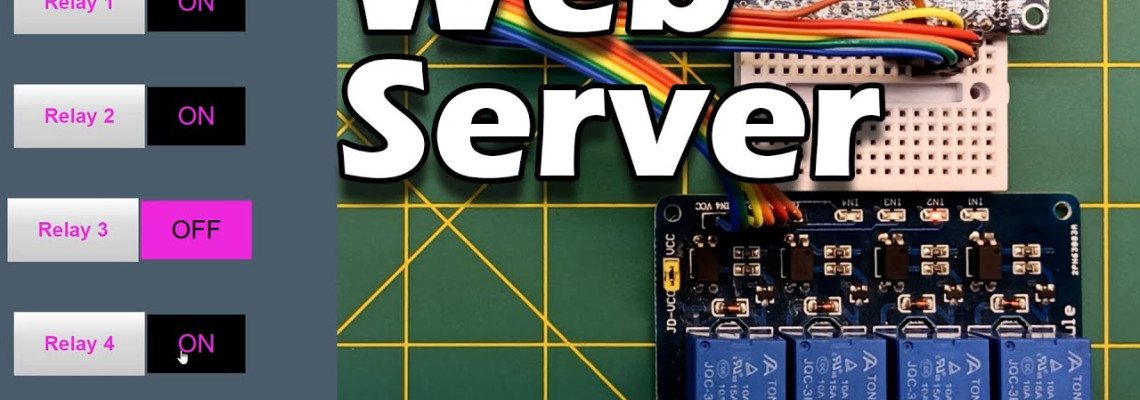
Dans ce tutoriel, nous allons construire un contrôle de serveur web pour un module relais 4 canaux avec ESP32.
Un module relais 4 canaux est un dispositif électronique conçu pour contrôler jusqu'à quatre circuits électriques distincts à l'aide d'un microcontrôleur basse tension ou d'un signal numérique.
Composants nécessaires:
Caractéristiques du module relais 4 canaux :
Nombre de canaux :
- Le module offre généralement quatre canaux de relais indépendants, permettant de contrôler jusqu'à quatre circuits électriques distincts.
Tension d'entrée :
- Le module de relais est conçu pour être contrôlé par une tension d'entrée basse, souvent 5V ou 3,3V. Cette tension d'entrée est généralement fournie par un microcontrôleur ou une source de signal numérique.
Tension de sortie :
- Les contacts du relais peuvent supporter des tensions plus élevées, couramment jusqu'à 250V en courant alternatif (CA) ou 30V en courant continu (CC). Cela permet de contrôler des dispositifs fonctionnant à des tensions de fonctionnement plus élevées.
Courant nominal :
- Chaque relais a un courant maximal spécifié qu'il peut commuter. Les valeurs courantes sont de 10A ou 30A, indiquant le courant maximal pouvant circuler à travers les contacts du relais.
Broches de contrôle :
- Le module dispose de broches d'entrée (telles que IN1, IN2, IN3, IN4) pour chaque canal de relais. Ces broches se connectent aux signaux de contrôle provenant d'un microcontrôleur ou d'un autre dispositif numérique.
Broches de mise à la terre commune et d'alimentation :
- Il y a généralement des broches communes de mise à la terre (GND) et d'alimentation (VCC) pour le circuit de contrôle. La broche VCC est utilisée pour alimenter le module.
Indicateurs LED :
- De nombreux modules de relais incluent des indicateurs LED pour chaque canal, fournissant une indication visuelle de l'état du relais (activé ou désactivé).
Isolation optique :
- Certains modules de relais disposent d'une isolation optique, où les circuits d'entrée et de sortie sont électriquement isolés. Cela aide à protéger le dispositif de contrôle contre d'éventuelles surtensions ou interférences électromagnétiques dans le circuit contrôlé.
Déclenchement haut niveau/bas niveau :
- Le module peut prendre en charge des entrées de déclenchement haut niveau ou bas niveau, permettant la compatibilité avec différents systèmes de microcontrôleurs.
Bornes à vis :
- Certains modules de relais sont équipés de bornes à vis pour une connexion facile et sécurisée des fils aux contacts du relais.
Conception compacte :
- Les modules de relais sont généralement conçus de manière compacte, les rendant adaptés à l'intégration dans divers projets électroniques et applications.
Lors de l'utilisation d'un module relais 4 canaux, il est essentiel de se référer à la fiche technique fournie par le fabricant pour des spécifications détaillées, des directives d'utilisation et des considérations de sécurité. Cela garantira une intégration appropriée et sécurisée dans vos projets.
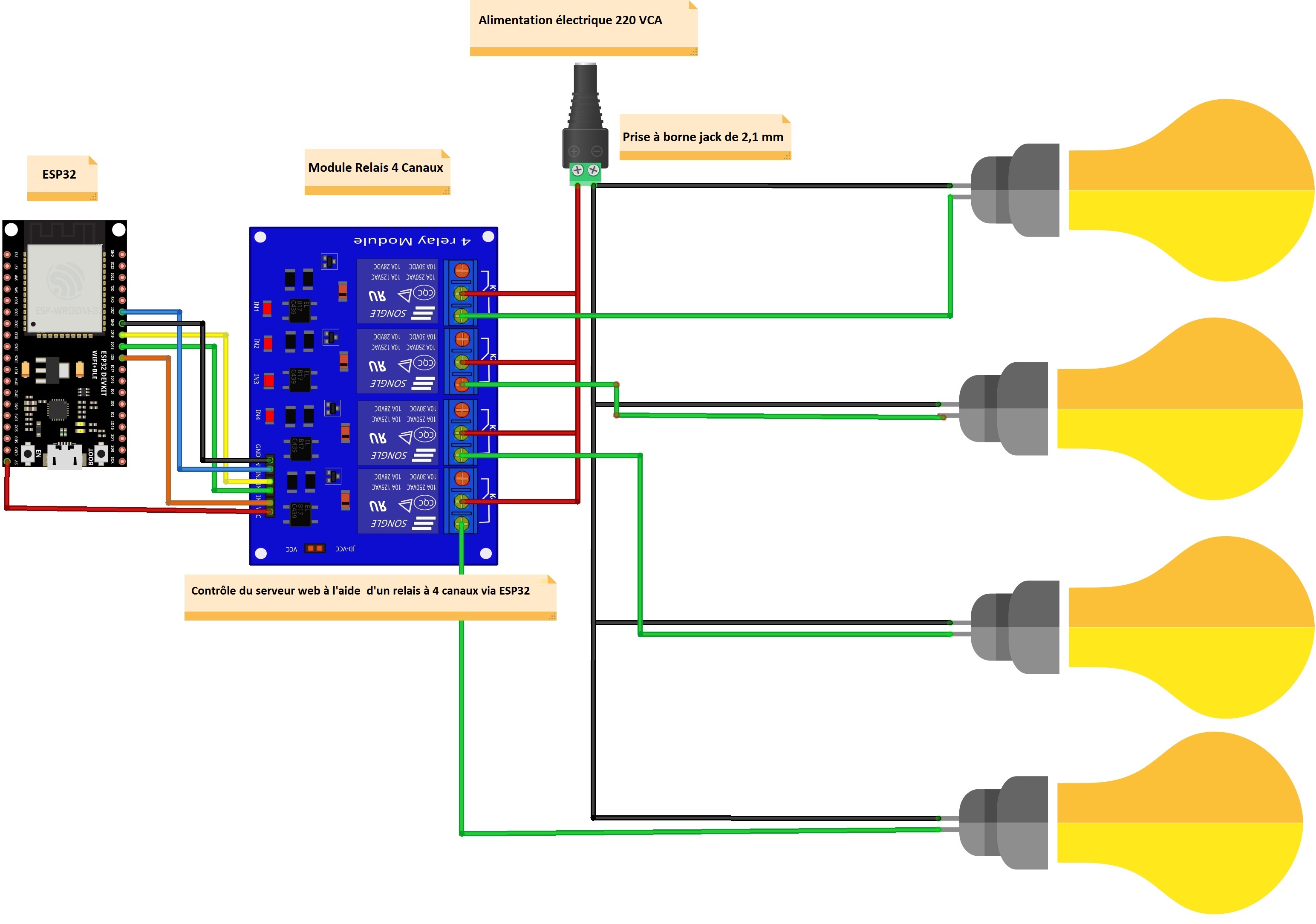
Schémas :
Programme:
// Importez les bibliothèques requises
#include "WiFi.h"
#include "ESPAsyncWebServer.h"
// Définissez sur vrai pour définir le relais comme normalement ouvert (NO)
#define RELAY_NO true
// Définissez le nombre de relais
#define NUM_RELAYS 4
// Affectez chaque GPIO à un relais
int relayGPIOs[NUM_RELAYS] = {5, 18, 19, 21};
// Remplacez par vos identifiants réseau
const char* ssid = "ssid";
const char* password = "password";
const char* PARAM_INPUT_1 = "relay";
const char* PARAM_INPUT_VOICE = "command";
// Create AsyncWebServer object on port 80
AsyncWebServer server(80);
// Le code HTML
const char index_html[] PROGMEM = R"rawliteral(
<!DOCTYPE html>
<html lang="en">
<head>
<meta charset="UTF-8">
<meta name="viewport" content="width=device-width, initial-scale=1.0">
<title><i class="fa fa-plug"></i> ESP32 4-Channel Relay Control</title>
<link rel="stylesheet" href="https://cdnjs.cloudflare.com/ajax/libs/font-awesome/5.15.1/css/all.min.css">
<style>
body {
font-family: 'Arial', sans-serif;
background-color: #f4f4f4;
text-align: center;
margin: 20px;
}
h2 {
color: #333;
}
.relayButton {
padding: 15px;
font-size: 18px;
margin: 10px;
cursor: pointer;
width: 200px;
border: 2px solid #3498db;
background-color: #3498db;
color: white;
border-radius: 8px;
outline: none;
transition: background-color 0.3s ease;
}
.relayButton:hover {
background-color: #2980b9;
}
.on {
background-color: #27ae60;
border: 2px solid #27ae60;
}
.toggleButton {
padding: 15px;
font-size: 18px;
margin: 10px;
cursor: pointer;
width: 200px;
border: 2px solid #e74c3c;
background-color: #e74c3c;
color: white;
border-radius: 8px;
outline: none;
transition: background-color 0.3s ease;
}
.toggleButton:hover {
background-color: #c0392b;
}
.fa {
margin-right: 5px;
}
.voiceButton {
padding: 15px;
font-size: 18px;
margin: 10px;
cursor: pointer;
width: 200px;
border: 2px solid #9b59b6;
background-color: #9b59b6;
color: white;
border-radius: 8px;
outline: none;
transition: background-color 0.3s ease;
}
.voiceButton:hover {
background-color: #8e44ad;
}
</style>
<script>
function toggleRelay(relayNumber) {
var xhr = new XMLHttpRequest();
xhr.onreadystatechange = function () {
if (xhr.readyState == 4 && xhr.status == 200) {
updateButton(relayNumber, xhr.responseText);
}
};
xhr.open("GET", "/toggle?relay=" + relayNumber, true);
xhr.send();
}
function updateButton(relayNumber, state) {
var button = document.getElementById("relay" + relayNumber);
button.innerHTML = "<i class='fa fa-lightbulb'></i> Relay " + relayNumber + ": " + (state === "1" ? "On" : "Off");
button.classList.toggle("on", state === "1");
}
function toggleAllRelays() {
var xhr = new XMLHttpRequest();
xhr.onreadystatechange = function () {
if (xhr.readyState == 4 && xhr.status == 200) {
var newState = xhr.responseText === "1" ? "On" : "Off";
for (var i = 1; i <= 4; i++) {
updateButton(i, xhr.responseText);
}
var toggleButton = document.getElementById("toggleButton");
toggleButton.innerHTML = "<i class='fa fa-lightbulb'></i> Toggle All: " + newState;
toggleButton.classList.toggle("on", xhr.responseText === "1");
}
};
xhr.open("GET", "/toggleAll", true);
xhr.send();
}
</script>
</head>
<body>
<h2><i class="fa fa-plug"></i> ESP32 4-Channel Relay Control</h2>
<div>
<button id="relay1" class="relayButton" onclick="toggleRelay(1)"><i class="fa fa-lightbulb"></i> Relay 1 : Off</button>
<button id="relay2" class="relayButton" onclick="toggleRelay(2)"><i class="fa fa-lightbulb"></i> Relay 2 : Off</button>
<br>
<button id="relay3" class="relayButton" onclick="toggleRelay(3)"><i class="fa fa-lightbulb"></i> Relay 3 : Off</button>
<button id="relay4" class="relayButton" onclick="toggleRelay(4)"><i class="fa fa-lightbulb"></i> Relay 4 : Off</button>
</div>
<button id="toggleButton" class="toggleButton" onclick="toggleAllRelays()"><i class="fa fa-lightbulb"></i> Toggle All: Off</button>
</body>
</html>
)rawliteral";
// Remplace le paramètre fictif par la section du bouton dans votre page web
String processor(const String& var){
//Serial.println(var);
if(var == "BUTTONPLACEHOLDER"){
String buttons ="";
for(int i=1; i<=NUM_RELAYS; i++){
buttons+= "<button id='relay" + String(i) + "' class='relayButton' onclick='toggleRelay(" + String(i) + ")'><i class='fa fa-lightbulb'></i> Relay " + String(i) + ": Off</button>";
}
return buttons;
}
return String();
}
void setup(){
// Port série à des fins de débogage
Serial.begin(115200);
// Set all relays to off when the program starts - if set to Normally Open (NO), the relay is off when you set the relay to HIGH
for(int i=1; i<=NUM_RELAYS; i++){
pinMode(relayGPIOs[i-1], OUTPUT);
if(RELAY_NO){
digitalWrite(relayGPIOs[i-1], HIGH);
}
else{
digitalWrite(relayGPIOs[i-1], LOW);
}
}
// // Se connecter au Wi-Fi
WiFi.begin(ssid, password);
while (WiFi.status() != WL_CONNECTED) {
delay(1000);
Serial.println("Connecting to WiFi..");
}
// Afiicher l'adresse IP locale de l'ESP32
Serial.println(WiFi.localIP());
// Route pour la page d'accueil / web
server.on("/", HTTP_GET, [](AsyncWebServerRequest *request){
request->send_P(200, "text/html", index_html, processor);
});
// Envoyer une requête GET à <ESP_IP>/toggle?relay=<relayNumber>
server.on("/toggle", HTTP_GET, [] (AsyncWebServerRequest *request) {
String inputMessage;
// Envoyer une requête GET à <ESP_IP>/toggle?relay=<relayNumber>
if (request->hasParam(PARAM_INPUT_1)) {
inputMessage = request->getParam(PARAM_INPUT_1)->value();
if(RELAY_NO){
Serial.print("NO ");
digitalWrite(relayGPIOs[inputMessage.toInt()-1], !digitalRead(relayGPIOs[inputMessage.toInt()-1]));
request->send(200, "text/plain", digitalRead(relayGPIOs[inputMessage.toInt()-1]) ? "1" : "0");
}
else{
Serial.print("NC ");
digitalWrite(relayGPIOs[inputMessage.toInt()-1], !digitalRead(relayGPIOs[inputMessage.toInt()-1]));
request->send(200, "text/plain", digitalRead(relayGPIOs[inputMessage.toInt()-1]) ? "1" : "0");
}
}
else {
inputMessage = "No relay number sent";
request->send(200, "text/plain", "0");
}
Serial.println(inputMessage);
});
server.on("/toggleAll", HTTP_GET, [] (AsyncWebServerRequest *request) {
// Obtenir l'état du premier relais (vous pouvez choisir n'importe quel relais pour représenter l'état)
int relayState = digitalRead(relayGPIOs[0]);
// Basculer tous les relais à l'état opposé
for (int i = 0; i < NUM_RELAYS; i++) {
digitalWrite(relayGPIOs[i], !relayState);
}
request->send(200, "text/plain", String(!relayState));
});
;
server.begin();
}
void loop() {}
Resultat:
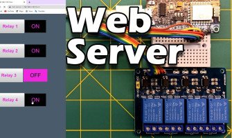
lorsque on insére l'adresse ip obtenue par l'esp32 dans un navigateur tels que google chrome ou opera ....etc ont obtient cette page
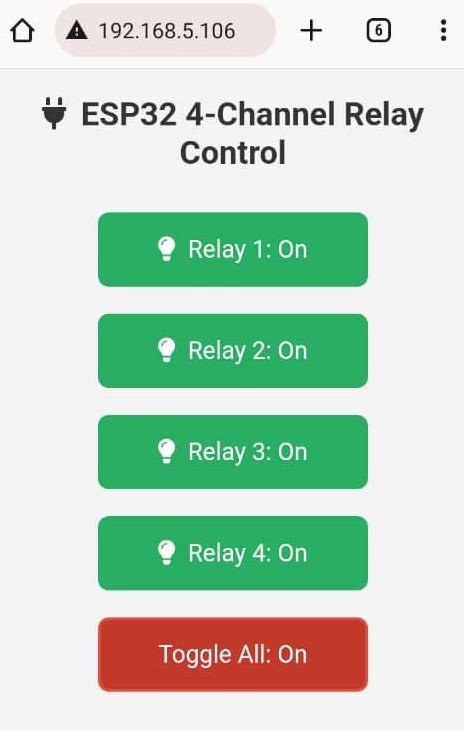
Chaque bouton dans cette page a un role précis:
Pour Relay 1,2,3,4:permetre d'allumer ou d'étiendre lampes,ou prises ou n'importe appareille connecté( 220VAC ou 30VDC l'alimentation).
Pour Toggle All :permetre déteindre ou allumer tout les appareille connecter dans les 4 relais

26 Commentaire (s)
Merci
C\'est bien, c\'est vraiment, la notion de IOT (internet of things), commander des objets à distance via internet (web service)...
Il reste une chose, il faut, protéger la page web par un mot de passe complexe, pour eviter les attaques......
I visited multiple web sites however the audio quality for audio songs present at this web site is really marvelous.
These are truly enormous ideas in concerning blogging. You have touched some good points here. Any way keep up wrinting.
I am sure this piece of writing has touched all the internet people, its really really good piece of writing on building up new web site.
If some one wishes expert view about blogging afterward i recommend him/her to pay a visit this web site, Keep up the pleasant job.
You\'ve made some decent points there. I checked on the web to learn more about the issue and found most people will go along with your views on this site.
I think the admin of this web site is in fact working hard for his web site, as here every material is quality based information.
Ahaa, its good discussion concerning this article at this place at this webpage, I have read all that, so at this time me also commenting at this place.
Hi, I do think this is a great site. I stumbledupon it ;) I may come back yet again since I book marked it. Money and freedom is the best way to change, may you be rich and continue to guide others.
Everything is very open with a precise description of the issues. It was truly informative. Your website is extremely helpful. Thanks for sharing!
Great article. I will be experiencing a few of these issues as well..
What\'s Taking place i\'m new to this, I stumbled upon this I have discovered It absolutely useful and it has aided me out loads. I hope to give a contribution & assist other users like its helped me. Great job.
Whoa! This blog looks exactly like my old one! It\'s on a completely different subject but it has pretty much the same page layout and design. Great choice of colors!
Hello, Neat post. There is an issue together with your site in internet explorer, might check this? IE still is the marketplace leader and a good component to other folks will leave out your great writing due to this problem.
I always was concerned in this topic and still am, thank you for putting up.
Thank you for the auspicious writeup. It in fact was a amusement account it. Look advanced to more added agreeable from you! By the way, how can we communicate?
I will right away clutch your rss feed as I can’t in finding your e-mail subscription hyperlink or newsletter service. Do you have any? Please allow me know so that I may just subscribe. Thanks.
Ahaa, its pleasant discussion concerning this paragraph here at this weblog, I have read all that, so at this time me also commenting at this place.
There\'s certainly a lot to learn about this subject. I love all of the points you made.
I\'ll right away take hold of your rss as I can\'t to find your e-mail subscription link or newsletter service. Do you\'ve any? Kindly let me understand in order that I could subscribe. Thanks.
I like it when folks come together and share views. Great site, stick with it!
This seems which includes a fairly great function, nicely finished
I conceive this web site has some really fantastic info for everyone :D.
Whoa! This blog looks just like my old one! It\'s on a completely different topic but it has pretty much the same page layout and design. Superb choice of colors!
Laissez un commentaire