


C'est Quoi Un ESP32 CAM:
L'ESP32-CAM est un petit module caméra qui intègre un chip ESP32-S (un module MCU polyvalent avec Wi-Fi, Bluetooth et BLE) avec une caméra. Ce module est très polyvalent et peut être utilisé dans divers projets d'automatisation domestique et IoT où la connectivité Internet et le traitement d'image sont nécessaires. Il est particulièrement prisé pour des tâches comme le streaming vidéo, la reconnaissance faciale et la surveillance générale.
Domaines d'Utilisation de l'ESP32-CAM:
Surveillance à domicile : Pour la surveillance de la sécurité domestique via le streaming vidéo à distance.
Surveillance industrielle : Utilisé dans les environnements industriels pour la surveillance des processus et la sécurité des équipements.
Surveillance environnementale : Surveillance de l'environnement pour la recherche et la protection de la faune.
Automatisation résidentielle : Intégration dans des systèmes d'automatisation de la maison pour le contrôle et la sécurité.
Projets éducatifs : Utilisé dans l'enseignement de la programmation, de la robotique et des systèmes embarqués.
Reconnaissance faciale et de mouvement : Applications nécessitant une identification visuelle pour la sécurité ou l'interaction utilisateur.
Caractéristiques Clés de l'ESP32-CAM:
| Processeur: | Le noyau est une puce ESP32, qui est dual-core et peut fonctionner jusqu’à 240 MHz. Il prend en charge des interfaces telles que SPI, I2C, UART, et plus encore. |
Wi-Fi et Bluetooth : | En tant que membre de la famille ESP32, il prend en charge la connectivité Wi-Fi et Bluetooth, ce qui lui permet de se connecter facilement à Internet ou d’autres appareils. |
| Caméra: | Le module utilise généralement une caméra OV2640 capteur capable de capturer des images de 2 mégapixels. |
| Petit facteur de forme | Il est très compact, ce qui le rend adapté aux petits projets IoT. |
| Faible coût : | Il est relativement peu coûteux, ce qui le rend accessible aux amateurs et aux professionnels. |
| GPIO Pins: | Comprend plusieurs broches GPIO pour connecter des périphériques et des capteurs. |
| Fente pour carte SD : | Pour le stockage embarqué, qui peut être utile pour enregistrer des photos et des vidéos. |
GPIO de l'ESP32-CAM:
L'ESP32-CAM dispose de plusieurs broches GPIO qui peuvent être utilisées pour différentes fonctions. Ces broches prennent en charge l'entrée et la sortie numériques, et certaines sont capables de gérer également des signaux analogiques. Elles permettent à l'ESP32-CAM de se connecter à une large gamme de périphériques tels que des capteurs, des actionneurs et d'autres modules. Les broches GPIO spécifiques varient selon la configuration de la carte et doivent être gérées avec soin pour éviter d'endommager le module.
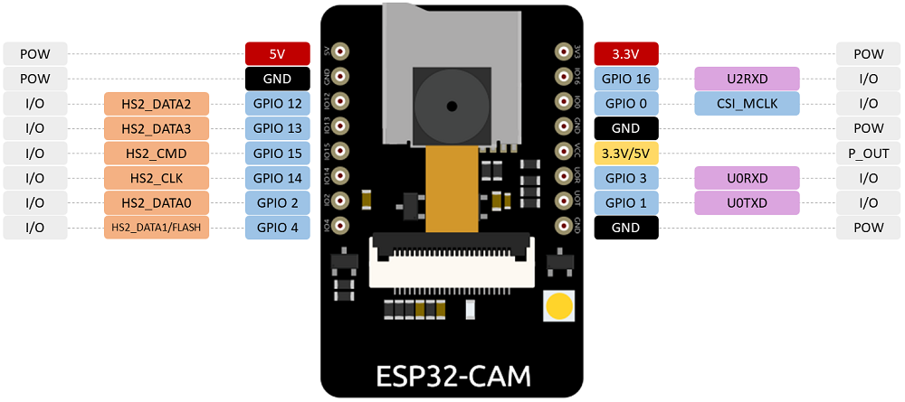
Pins disponibles :
- GPIO 0 - Utilisé souvent pour déterminer si l'ESP32 est en mode programmation. Il peut également servir comme entrée/sortie générale.
- GPIO 1 - Généralement réservé pour le TX UART pendant la programmation et le débogage, il peut être indisponible pour d'autres utilisations si la communication série est nécessaire.
- GPIO 2 - Disponible pour une entrée/sortie générale. Connecté également à la LED embarquée, utile pour des signaux de feedback basiques.
- GPIO 3 - Généralement réservé pour le RX UART pendant la programmation et le débogage, il peut être indisponible pour d'autres utilisations si la communication série est nécessaire.
- GPIO 4 - Disponible pour une entrée/sortie générale et souvent utilisé pour la communication avec la carte SD.
- GPIO 12 - Peut être utilisé pour une entrée/sortie générale. Attention à l'utilisation de cette broche au démarrage car elle peut affecter le mode de démarrage si elle est haute.
- GPIO 13 - Disponible pour une entrée/sortie générale, souvent utilisé pour connecter des capteurs supplémentaires ou des actionneurs.
- GPIO 14 - Disponible pour une entrée/sortie générale, souvent utilisé comme horloge pour la carte SD.
- GPIO 15 - Disponible pour une entrée/sortie générale. Utilisé aussi pour les signaux de commande de la carte SD.
- GPIO 16 - Peut être utilisé pour une entrée/sortie générale, souvent utilisé comme pin de réinitialisation pour le module de la caméra.
- GPIO 17 - Disponible pour une entrée/sortie générale, souvent utilisé en connexion avec le module de la caméra.
Considérations Spéciales
- GPIO 0 doit être à l'état bas au démarrage pour entrer en mode de programmation, ce qui est crucial lors de la mise à jour du firmware.
- GPIO 12 doit être à l'état bas lors du démarrage pour éviter de démarrer en mode téléchargement. Cette broche fait également partie de l'interface de la carte SD.
- GPIO 15 doit être tiré vers le bas au démarrage pour garantir le mode de démarrage correct.
Recommandations d'Utilisation
- Pour les applications nécessitant une communication numérique (UART, I2C, SPI), utilisez les GPIOs 4, 12, 13, 14 et 15 car ils supportent de telles fonctionnalités sans interférer avec les opérations de la caméra.
- Lors de l'utilisation de la fonctionnalité de carte SD, assurez-vous que les GPIOs 4, 12, 13, 14 et 15 sont correctement configurés et ne sont pas utilisés à des fins contradictoires.
- Évitez d'utiliser les GPIOs 1, 3, 6, 7, 8, 9, 10, 11 (qui ne sont généralement pas disponibles sur l'ESP32-CAM mais sont réservés pour des connexions internes comme la mémoire flash et l'interface de la caméra).
- L'ESP32-CAM offre des configurations de broches GPIO flexibles mais nécessite une planification minutieuse et une compréhension du comportement de démarrage et opérationnel de chaque broche pour éviter les pièges courants dans le développement d'applications.
Programmation:
La programmation du module ESP32-CAM nécessite plusieurs étapes et des outils spécifiques. Voici un guide général sur la façon de programmer l'ESP32-CAM en utilisant l'Arduino IDE :
Matériaux nécessaires :
- Module ESP32-CAM - Le module caméra qui inclut la puce ESP32.
- Adaptateur FTDI - Un convertisseur USB vers série pour connecter l'ESP32-CAM à un ordinateur ou Programmeur USB ESP32 dédié - Ces appareils sont spécialement conçus pour la programmation des dispositifs ESP32 et incluent souvent des fonctionnalités telles que l'auto-réinitialisation et l'auto-programmation qui simplifient le processus de flashage.
- Fils jumpers - Pour faire les connexions nécessaires entre l'adaptateur FTDI et l'ESP32-CAM.
- Câble micro USB - Pour connecter l'adaptateur FTDI à l'ordinateur.
Configurer l'Arduino IDE
- Installer l'Arduino IDE - Téléchargez-le depuis le site officiel d'Arduino.
- Installer le support de carte ESP32 :
- Dans l'Arduino IDE, allez à Fichier > Préférences.
- Ajoutez l'URL suivante dans “URLs de gestionnaire de cartes supplémentaires” :
https://dl.espressif.com/dl/package_esp32_index.json - Ouvrez Outils > Carte > Gestionnaire de cartes, cherchez ESP32 et installez-le.
- Sélectionnez votre carte :
- Allez à Outils > Carte et sélectionnez "AI Thinker ESP32-CAM" ou similaire.
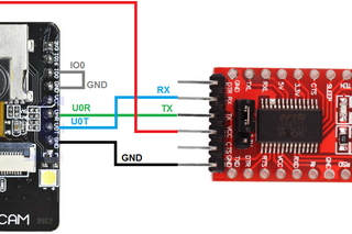
Connectez l'ESP32-CAM au programmeur USB La plupart des programmeurs USB dédiés pour l'ESP32 correspondent à la disposition des broches de l'ESP32-CAM, permettant une connexion directe. Utilisez des fils jumpers si nécessaire pour correspondre aux broches correspondantes :
- TX à RX
- RX à TX
- GND à GND
- 5V à 5V (assurez-vous que votre programmeur supporte le niveau de tension requis par l'ESP32-CAM)
Programmer l'appareil
- Connectez le programmeur à votre ordinateur - Utilisez le câble USB.
- Ouvrez votre code dans l'Arduino IDE - Commencez avec un exemple de sketch sous Fichier > Exemples > ESP32 > Camera.
- Sélectionnez le bon port COM - Sous Outils > Port, sélectionnez le port COM associé à votre programmeur.
- Téléchargez votre sketch - Appuyez sur le bouton de téléchargement.
Dépannage
- Erreurs de téléchargement : Assurez-vous que les pilotes corrects pour votre programmeur USB sont installés sur votre ordinateur. Revérifiez le port COM et les paramètres de la carte dans l'Arduino IDE.
- Aucune réponse du module : Vérifiez que toutes les connexions sont sécurisées et correctes. Vérifiez si l'ESP32-CAM nécessite des réglages spécifiques de cavaliers sur le programmeur pour une communication réussie.
L'utilisation d'un programmeur USB dédié simplifie grandement le processus de programmation de l'ESP32-CAM en gérant des aspects tels que la sélection du mode de démarrage et la réinitialisation, rendant le développement plus rapide et plus efficace. Cela est particulièrement utile pendant les cycles de développement et de test répétés.
2559 Commentaire (s)
FB88 luôn đưa ra các giải thưởng hấp dẫn cho người chơi, khiến tôi cảm thấy rất vui.\r\nTôi rất thích các trò chơi live casino của FB88, họ mang lại cảm giác như đang chơi trực tiếp tại casino.\r\nFB88 cung cấp các chương trình khuyến mãi rất hấp dẫn, người chơi có cơ hội nhận giải thưởng lớn.
This is actually a really practical guide ????\r\n\r\nI like how you explained the ESP32-CAM in a simple way, especially how it combines camera + WiFi + Bluetooth in one small module. Makes it feel very powerful for IoT and surveillance type projects.\r\n\r\nI also checked a bit more, and it’s true that people use it a lot for things like live streaming, face detection, and smart home projects because it’s cheap and flexible ????\r\n\r\nHonestly, this is one of those posts that makes electronics feel much easier to understand even for beginners.
Các chương trình khuyến mãi của họ rất hấp dẫn, mang lại nhiều lợi ích cho người chơi.\r\nTôi cảm thấy rất an toàn khi chơi tại FB88, họ có các biện pháp bảo mật rất nghiêm ngặt.\r\nFB88 cung cấp trải nghiệm chơi game mượt mà.
At NEURA PULSE, we provide powerful AI tools to boost your online visibility and automate growth.\r\nOur platform helps you build, deploy, and scale AI solutions with ease and efficiency.\r\nFrom SEO optimization to smart automation, we have the tools to grow your digital presence.\r\nContact us today to leverage AI and take your business visibility to the next level.
Yes.. You can set it up for remote video streaming to keep an eye on your home or use it in an industrial setting to monitor equipment. It’s also great for educational projects, helping students learn about programming and robotics. Plus, with its capabilities for facial and motion recognition, it\'s perfect for any security or user interaction applications. Overall, the ESP32-CAM is an excellent choice if you\'re looking to dive into IoT projects or enhance your home automation system!
Scopro tutti i mercati di scommessa disponibili su Betonred, anche i più insoliti. Dall\'Handicap Asiatico alle scommesse sul numero di corner, non lascio nulla al caso.
わたくしは、テッドベットカジノのヘビーユーザーとして情報を発信しています。当サイトでは、信頼できるレビューを公開しています。私の目標は、あなたがテッドベットで勝利を掴むための手助けをすることです
Je suis un architecte de stratégies de jeu, bâtissant des systèmes pour différents jeux. Je vous fournis les schémas précis pour que vous puissiez les mettre en pratique.
Je suis un chercheur d\'offres spécialisé sur le Golden Panda Casino. Ne loupez plus jamais une occasion exceptionnelle de augmenter votre capital.\r\nhttps://j3clusters.com/author/jaymenesmith04/\r\nhttps://digitalafterlife.org/@donettemendiol?page=about\r\nhttps://ssbalkitkk.com.tr/employer/golden-panda-casino-fr/\r\nhttps://git.ja-schwarz.de/bobbyet2682951\r\nhttp://www.tengenstudio.com:3000/ztqthaddeus745\r\nhttps://thelegallock.com/job/companies/golden-panda-casino-fr/\r\nhttps://git.voxtor.ir/aracelisweaver\r\nhttp://47.92.23.195:8418/aliciamaye6821/8515golden-panda-casino-fr.com/wiki/Golden-Panda-Casino%3A-A-Retrospective-Look-at-a-Gaming-Empire\r\nhttp://www.jingniannian.cn:2195/alannah28t9272\r\nhttp://gitea.kongxq.fun/kraigstirling6
Play 99 Exchange Login enables users to securely access their accounts with a simple login process.
Je suis le dénicheur de trésors au sein du large éventail de jeux du Golden Panda Casino. Laissez-moi vous montrer mes dernières trouvailles.\r\nhttps://git.zhengjin.pub/luciennemyz132\r\nhttps://nojoom.net/@linettetripp49?page=about\r\nhttps://git.iacovlevdev.com/kelsey06g48288\r\nhttps://ssrealestate.ae/author/tammiekayser96/\r\nhttp://161.189.128.194:3000/tommyosburn165\r\nhttp://git.delphicom.net/patbraine95705/pat1986/issues/1\r\nhttps://ai-follow.com/read-blog/1460_golden-panda-casino-a-deep-dive-into-fortune-and-controversy.html\r\nhttps://tee.eddykk.com/sibyl97h024489/golden-panda-casino-fr.com2960/wiki/Golden-Panda-Casino%3A-A-Deep-Dive-into-an-Imaginary-Gaming-Paradise\r\nhttps://repo.divisilabs.com/vansoul543560\r\nhttps://jamdiggy.com/charmainkiel7
Mijn woorden dient als een schakel tussen de ondoorzichtige casinowereld en de enthousiaste gokker. Ik vertaal de details en strategieën voor iedereen.
Ik bekijk gokken als een kunde die je kunt verbeteren. Op deze blog voorzie ik je de oefeningen om je spelniveau te verhogen.
Ik heb een intense voorkeur voor de getallen achter kansspelen. We ontcijferen gezamenlijk we de mogelijkheden en vergroten we jouw winstpotentieel.
Ik meen oprecht in de kracht van de gemeenschap. Bespreek je verhalen en drop je vragen in de comments.
Ik zet om complexe instructies en tactieken naar eenvoudige taal. Zelfs als absolute starter voel je je rap op je gemak in het casino.
Play Exchange 99 offers a seamless platform experience with secure access and responsive performance.
Mijn manier van schrijven is helder en bedoeld voor resultaat. Geen onzin, alleen de kennis die je assisteert om slimmer te spelen.
Ik ben een verhalenverteller die zich afspelen rond de pokertafels van de wereld. Bereid je voor voor anekdotes vol drama en onverwachte wendingen.
Ik benadruk het de noodzaak van verstandig bankroll management. Het is de sleutel tot duurzaam succes in het casino.
Discover How to Build an AI Tool in 2026: Step-by-Step Guide for Beginners — NeuraPulse, a practical and human-focused guide designed to help you turn ideas into real AI products. Learn how to identify a problem, choose the right AI models, build with simple tools, and create a smooth user experience that people actually enjoy. This guide explains everything in an easy, step-by-step way so even beginners can start building confidently. With insights from NeuraPulse, you’ll understand how to test, launch, and improve your AI tool for real-world success and visibility.
Mon leitmotiv : parier plus efficacement, pas plus. Je vous explique la gestion de bankroll appliquée au Golden Panda Casino.\r\nhttps://git.hundseth.com/nannieelliston\r\nhttps://divinerealty.online/author/zellachinnery/\r\nhttps://gitlab.xirus.co:8000/asacornell0977/asa1980/issues/1\r\nhttp://152.136.126.252:3000/adrienekossak\r\nhttps://www.sonaydoo.com/read-blog/1803_the-rise-and-fall-of-golden-panda-casino-a-glimpse-into-macau-039-s-gaming-boom.html\r\nhttp://121.196.13.116/roland69811924\r\nhttp://111.229.119.10:3000/mattietrower4\r\nhttps://empleo.infosernt.com/employer/golden-panda-casino-fr/\r\nhttp://git.ybrsmfw.cn/ekfmanie177127/golden-panda-casino5372/wiki/Golden-Panda-Casino:-A-Glimpse-into-a-World-of-Luck%2C-Luxury%2C-and-Legacy\r\nhttp://114.241.105.134:7300/deantennant237
Mijn toezegging aan jou is simpel: content die relevant is en je echt helpt. Ik elimineer de ruis en geef je puur waardevol advies.
Mijn focus ligt op het ontdekken van de bijzondere spellen die je niet overal vindt. Ik geniet van het testen van onbekende spellen en het delen van mijn vondsten.
Ik zie mezelf als een moderne ontdekkingsreiziger in de enorme wereld van online gokken. Mijn logboek is deze blog, barstensvol met ontdekkingen.
Play99Exch Com Login provides secure account access with convenient login functionality.
Ik geloof dat verantwoord spelen de sleutel is tot langdurig plezier. Daarom richten we ook aandacht aan budgetten.
Ik ben een meester in het identificeren van waarde waar anderen die missen. Laat mij je leren waar je moet zoeken.
De het universum van gokkasten is mijn territorium. Ik decodeer de volatiliteit en de algoritmes van elke gokkast die ik vind.
Van het selecteren van een welkomstbonus tot het uitvoeren van een uitbetaling, ik begeleid je door elke stap. Mijn instructies zijn gemaakt voor volledige beginners.
Play99Exch Com Login offers secure authentication with smooth account access and reliable performance.
Iedere blogpost dat ik schrijf is gevuld met jarenlange praktijkkennis. Dit is geen hypothese, maar bewezen strategie.
Met jarenlange ervaring publiceer ik mijn directe mening over allerlei goksites. Transparantie blijft bij mij constant voorop.
Way cool! Some extremely valid points! I appreciate you writing this write-up plus the rest of the website is also really good.
I wanted to thank you for this excellent read!! I certainly loved every bit of it. I have got you bookmarked to look at new things you
Ik jaag constant naar die ene progressieve jackpot die het leven kan veranderen. Mijn zoektocht en tactieken noteer ik hier.
Hi, I do believe this is a great site. I stumbledupon it ;) I may return once again since I saved as a favorite it. Money and freedom is the best way to change, may you be rich and continue to help others.
Hi colleagues, its enormous article on the topic of cultureand entirely explained, keep it up all the time.
Hi, I do believe this is an excellent web site. I stumbledupon it ;) I will come back once again since I bookmarked it. Money and freedom is the greatest way to change, may you be rich and continue to guide others.
Je convertis des heures de jeu en conseils utiles. Gagnez du temps en lisant mes bilans sur Winoui Casino.\r\nhttp://skupra-nat.uamt.feec.vutbr.cz:30000/latoyaboston75/winoui-777.com1996/-/issues/1\r\nhttp://www.allarabjobs.com/employer/winoui-777\r\nhttps://www.lyvystream.com/@isabellporcell?page=about\r\nhttps://www.hirecybers.com/companies/winoui-777/\r\nhttps://futures-consulting.de/employer/winoui-777/\r\nhttps://www.florevit.com/read-blog/54604_who-else-needs-to-enjoy-securite-retrait-winoui.html\r\nhttps://git.seembox.com/callum7096692/7682091/wiki/How+To+Use+Retrait+Facile+WinOui+To+Desire\r\nhttp://git.oksei.ru/nora65l306870\r\nhttps://pl-property.com/author/silkeedgerton0/\r\nhttps://careers.universalair.aero/employer/winoui-777/
I’ll right away grasp your rss feed as I can not to find your e-mail subscription hyperlink or e-newsletter service. Do you’ve any? Kindly let me recognise in order that I may subscribe. Thanks.
You\'ve made some really good points there. I checked on the web for additional information about the issue and found most people will go along with your views on this web site.
I like it when folks come together and share views. Great blog, continue the good work!
I’ve seen great feedback from people who tried rtt singapore to overcome stress, anxiety, and self-doubt. It’s amazing how fast the mind can shift with the right guidance.
If you’re trying to find trustworthy consultants, reading recent whs reviews can give you a good sense of who delivers consistent results.
You have made some decent points there. I looked on the internet for more info about the issue and found most people will go along with your views on this site.
The right commercial umbrella not only provides shade but also defines outdoor dining spaces beautifully.
Have you been trying to get a full license in UK but is not possible or are u in UK and u need a driver license but u do not have papers to stay in UK or u do not know how to speak English well,might be your work does not give u time , here is an opportunity for you to get your government registered license without u seating for any test, we take care of everything till your license is out and sent to you, just WhatsApp us +44 7787 275165\r\n\r\nhttps://fulldocuments.co.uk/
Hi, I do think this is an excellent web site. I stumbledupon it ;) I am going to revisit once again since I book marked it. Money and freedom is the best way to change, may you be rich and continue to guide other people.
I will immediately grasp your rss feed as I can’t find your email subscription hyperlink or newsletter service. Do you’ve any? Please let me know in order that I may subscribe. Thanks.
Space Landscape Designs takes landscaping to another level — it’s not just about aesthetics, but also about creating spaces people genuinely enjoy living in. That’s true landscape design Sydney.
nice
What makes rtt therapy so effective is how it bridges the gap between awareness and action—it doesn’t just identify the issue but helps rewire how you think about it.
You have made some good points there. I checked on the web for more information about the issue and found most individuals will go along with your views on this web site.
I am not sure where you’re getting your info, but great topic. I needs to spend some time learning much more or understanding more. Thanks for great info I was looking for this information for my mission.
Having trouble logging into Crypto.com? Discover solutions for common login issues like password errors, 2FA problems, and app glitches. Learn how to reset your credentials, update the app, or contact support. This quick guide helps you fix login problems and regain secure access to your Crypto.com account on both mobile and desktop platforms.
Facing Crypto.com login issues? Find quick fixes for common problems like incorrect passwords, 2FA failures, and app errors. Learn how to reset your login details, troubleshoot access issues, and contact support if needed. Regain secure access to your Crypto.com account with this helpful guide for both mobile and desktop users.
Hello, Neat post. There is an issue with your web site in web explorer, may test this… IE nonetheless is the market chief and a huge section of other folks will pass over your excellent writing because of this problem.
https://www.eljnoub.com/\r\nhttps://www.eljnoub.com/\r\nhttps://www.eljnoub.com/\r\nhttps://www.rauhane.net\r\nhttps://www.s3udy.org/\r\nhttps://sexalarab.eu/\r\nhttps://hurenberlin.com/\r\nhttp://buybacklink.de/\r\nhttp://bestbacklinks.de\r\nhttp://backlinkservices.de\r\nhttps://www.q8yat.org/\r\nhttps://www.elso9.com/\r\nhttps://jalbalhabeb.org\r\nhttps://wikimedia.cc\r\nhttps://hurenberlin.com/\r\nhttps://www.elso9.com/\r\nhttps://www.eljnoub.com/\r\nhttps://www.q8yat.org/\r\nhttps://www.rauhane.net\r\nhttps://www.jeouzal.org\r\nhttps://www.alfalaki.net\r\nhttps://www.jaouzal.org\r\nhttps://casinoberlin.eu/\r\nhttps://www.sheikhrohani.de\r\nhttps://www.myemairat.de\r\nhttps://www.saudieonline.de\r\nhttps://www.nejetaa.de\r\nhttps://www.iesummit.de\r\nhttps://www.jalbalhabeb.de\r\nhttps://www.alukah.de\r\nhttps://www.mqaall.de\r\nhttps://www.elbalad.de\r\nhttps://www.muhtwa.de\r\nhttps://www.mawdoo3.de
Hello, you used to write excellent, but the last several posts have been kinda boring… I miss your tremendous writings. Past few posts are just a little bit out of track! come on!
Paragraph writing is also a excitement, if you know then you can write if not it is complicated to write.
https://www.rabotaescort.com/
https://www.istanbulswingers.com/
https://www.acompanhanteseuropa.com/
https://www.escortwork.net/
https://www.escortbasvuruajans1.com/
I love what you guys are usually up too. Such clever work and coverage! Keep up the good works guys I\'ve added you guys to our blogroll.
Way cool! Some very valid points! I appreciate you writing this write-up and the rest of the site is very good.
Wow, this article is fastidious, my younger sister is analyzing these kinds of things, thus I am going to convey her.
Heya i’m for the primary time here. I came across this board and I in finding It truly useful & it helped me out a lot. I’m hoping to present something again and aid others like you aided me.
Yes, produce a mobile transaction, create your card information and adata association is needed to obtain the RBC Budget software.
I’ll immediately seize your rss as I can’t in finding your e-mail subscription hyperlink or e-newsletter service. Do you’ve any? Kindly allow me recognize so that I may just subscribe. Thanks.
The Phottix Ares, pictured above, are solid remotes and sell for about $55 a set They have eight channels, run on (included) AA batteries, work in the 2.4GHz frequency and come with a one-year factory warranty.
Explore the profound effects of our DMT Vape Pen, designed for those seeking a unique and transformative experience. This pen offers a convenient way to access DMT’s powerful insights and creativity, all in a user-friendly format.\r\nhttps://expresspsychedelic.com/product/dmt-vape-pen/
After looking into a number of the blog posts on your blog, I truly like your way of writing a blog. I book-marked it to my bookmark website list and will be checking back soon. Please check out my web site as well and tell me your opinion.
I\'m not sure the place you\'re getting your info, but great topic. I needs to spend a while studying much more or figuring out more. Thanks for excellent info I used to be searching for this information for my mission.
The PayPal login is a fast, easy to use, and well-organized platform for a secured transaction of money across the globe online. The following are the main reasons why individuals from different backgrounds choose to bank with Capital One.
The steps given below will walk you through the easy procedure that you must follow for a quick Capital One login: Capital One also recommends changing your password regularly to enhance account security.
It\'s a shame you don\'t have a donate button! I\'d definitely donate to this fantastic blog! I guess for now i\'ll settle for book-marking and adding your RSS feed to my Google account. I look forward to new updates and will talk about this blog with my Facebook group. Talk soon!
Do you mind if I quote a couple of your articles as long as I provide credit and sources back to your website? My blog site is in the exact same area of interest as yours and my users would truly benefit from some of the information you provide here. Please let me know if this ok with you. Thanks!
Today, while I was at work, my cousin stole my iphone and tested to see if it can survive a 40 foot drop, just so she can be a youtube sensation. My apple ipad is now broken and she has 83 views. I know this is completely off topic but I had to share it with someone!
Hello there! I could have sworn I\'ve been to this site before but after checking through some of the post I realized it\'s new to me. Anyhow, I\'m definitely happy I found it and I\'ll be bookmarking and checking back frequently!
Great post. I was checking constantly this blog and I am impressed! Extremely helpful information particularly the last part :) I care for such info a lot. I was looking for this certain info for a very long time. Thank you and best of luck.
Hello, I enjoy reading all of your post. I like to write a little comment to support you.
I think the admin of this web page is genuinely working hard in favor of his site, since here every information is quality based information.
Hello, i think that i noticed you visited my weblog thus i came to go back the favor?.I am attempting to in finding issues to enhance my site!I guess its adequate to use some of your concepts!!
I think this is among the most significant info for me. And i am glad reading your article. But should remark on some general things, The web site style is wonderful, the articles is really nice : D. Good job, cheers
It\'s going to be end of mine day, but before end I am reading this enormous post to increase my experience.
Every weekend i used to visit this site, because i wish for enjoyment, for the reason that this this web site conations really fastidious funny data too.
Can you tell us more about this? I\'d love to find out some additional information.
You can certainly see your expertise within the article you write. The sector hopes for more passionate writers like you who are not afraid to mention how they believe. All the time go after your heart.
This article offers clear idea in favor of the new viewers of blogging, that truly how to do blogging and site-building.
Howdy, i read your blog occasionally and i own a similar one and i was just wondering if you get a lot of spam remarks? If so how do you reduce it, any plugin or anything you can suggest? I get so much lately it\'s driving me crazy so any help is very much appreciated.
What\'s up, every time i used to check website posts here in the early hours in the morning, for the reason that i enjoy to find out more and more.
Cool blog! Is your theme custom made or did you download it from somewhere? A design like yours with a few simple adjustements would really make my blog stand out. Please let me know where you got your theme. Cheers
I could not refrain from commenting. Well written!
Its like you read my mind! You appear to know so much about this, like you wrote the book in it or something. I think that you can do with some pics to drive the message home a bit, but other than that, this is magnificent blog. A fantastic read. I will certainly be back.
Woah! I\'m really digging the template/theme of this site. It\'s simple, yet effective. A lot of times it\'s difficult to get that "perfect balance" between usability and visual appearance. I must say you\'ve done a excellent job with this. In addition, the blog loads extremely fast for me on Firefox. Excellent Blog!
Thank you for some other wonderful article. Where else may anybody get that type of info in such a perfect way of writing? I have a presentation subsequent week, and I\'m on the look for such info.
I am regular reader, how are you everybody? This article posted at this site is genuinely nice.
I think the admin of this site is really working hard for his web site, for the reason that here every material is quality based information.
I really like your blog.. very nice colors & theme. Did you design this website yourself or did you hire someone to do it for you? Plz reply as I\'m looking to create my own blog and would like to find out where u got this from. many thanks
Hi, yes this post is truly fastidious and I have learned lot of things from it concerning blogging. thanks.
Paragraph writing is also a excitement, if you be familiar with then you can write if not it is complex to write.
I am genuinely pleased to read this blog posts which includes lots of valuable information, thanks for providing such data.
Keep on writing, great job!
I\'ve been browsing online greater than three hours lately, yet I never discovered any attention-grabbing article like yours. It\'s pretty value sufficient for me. Personally, if all web owners and bloggers made good content as you did, the internet will probably be much more useful than ever before.
Hi there colleagues, how is all, and what you want to say about this paragraph, in my view its in fact remarkable designed for me.
Thankfulness to my father who told me about this website, this webpage is genuinely amazing.
It\'s very trouble-free to find out any topic on web as compared to textbooks, as I found this piece of writing at this site.
Hi it\'s me, I am also visiting this website regularly, this web site is really nice and the users are in fact sharing good thoughts.
Link exchange is nothing else except it is simply placing the other person\'s website link on your page at appropriate place and other person will also do same in favor of you.
As i purchased with your blog site while positioning fascination purely a little bit little submits. Fulfilling technique for extended, We will be book-marking during a period attain forms finish happens further up.
An outstanding share! I have just forwarded this onto a co-worker who was doing a little research on this. And he actually ordered me dinner due to the fact that I found it for him... lol. So let me reword this.... Thank YOU for the meal!! But yeah, thanx for spending the time to discuss this subject here on your web site.
Have you ever considered writing an e-book or guest authoring on other sites? I have a blog based on the same information you discuss and would love to have you share some stories/information. I know my viewers would appreciate your work. If you are even remotely interested, feel free to send me an e mail.
Hey there! I just wanted to ask if you ever have any issues with hackers? My last blog (wordpress) was hacked and I ended up losing months of hard work due to no back up. Do you have any solutions to protect against hackers?
If some one needs to be updated with most up-to-date technologies after that he must be go to see this website and be up to date all the time.
An outstanding share! I have just forwarded this onto a coworker who was conducting a little research on this. And he actually ordered me lunch because I stumbled upon it for him... lol. So let me reword this.... Thank YOU for the meal!! But yeah, thanx for spending the time to discuss this subject here on your website.
excellent put up, very informative. I wonder why the other experts of this sector do not understand this. You must proceed your writing. I am confident, you have a great readers\' base already!
Unquestionably consider that that you said. Your favourite justification appeared to be at the web the simplest thing to remember of. I say to you, I definitely get annoyed at the same time as other people consider issues that they just do not recognise about. You managed to hit the nail upon the highest as neatly as outlined out the whole thing without having side effect , other folks could take a signal. Will probably be again to get more. Thanks
Incredible points. Great arguments. Keep up the amazing effort.
Wow, this article is fastidious, my sister is analyzing such things, therefore I am going to convey her.
When some one searches for his required thing, therefore he/she wants to be available that in detail, so that thing is maintained over here.
Thanks for sharing your thoughts on ESP32. Regards
Hello terrific blog! Does running a blog like this require a great deal of work? I have virtually no understanding of coding however I was hoping to start my own blog soon. Anyhow, should you have any ideas or tips for new blog owners please share. I know this is off topic nevertheless I just wanted to ask. Cheers!
Very good write-up. I absolutely love this site. Thanks!
Remarkable issues here. I am very satisfied to peer your post. Thank you so much and I am taking a look forward to contact you. Will you please drop me a e-mail?
My coder is trying to convince me to move to .net from PHP. I have always disliked the idea because of the costs. But he\'s tryiong none the less. I\'ve been using Movable-type on a variety of websites for about a year and am worried about switching to another platform. I have heard very good things about blogengine.net. Is there a way I can transfer all my wordpress posts into it? Any help would be really appreciated!
This article is really a pleasant one it helps new the web visitors, who are wishing in favor of blogging.
Greetings! Very useful advice within this article! It\'s the little changes that will make the biggest changes. Many thanks for sharing!
Home Depot Home Depot helps people do more with their time and hard-earned dollars. Find everything from a small vases to large furniture in the Home Depot. Find departments such as Appliances Plumbing, Cleaning, and much more. Each department provides a vast range of items that will assist you in getting the task accomplished. No matter if you\'re looking to update the cabinets\' fixtures or building a deck, you\'ll locate the right tools and materials in Home Depot.
This paragraph will help the internet visitors for creating new website or even a blog from start to end.
I’ve checked a few Mumbai call girl pages before, but this one feels more organized and less confusing.
I am sure this paragraph has touched all the internet visitors, its really really fastidious post on building up new weblog.
What a material of un-ambiguity and preserveness of precious experience on the topic of unpredicted emotions.
I don\'t even know how I ended up here, but I thought this post was good. I don\'t know who you are but definitely you\'re going to a famous blogger if you are not already ;) Cheers!
Remarkable issues here. I\'m very glad to see your post. Thanks so much and I am having a look ahead to contact you. Will you please drop me a e-mail?
Does your blog have a contact page? I\'m having problems locating it but, I\'d like to shoot you an e-mail. I\'ve got some creative ideas for your blog you might be interested in hearing. Either way, great website and I look forward to seeing it expand over time.
This piece of writing will help the internet people for building up new web site or even a weblog from start to end.
Excellent post. I was checking constantly this blog and I\'m impressed! Extremely helpful information particularly the last part :) I care for such information a lot. I was seeking this certain information for a long time. Thank you and good luck.
My family members always say that I am killing my time here at web, however I know I am getting familiarity all the time by reading thes fastidious content.
Saved as a favorite, I love your blog!
Article writing is also a fun, if you be familiar with after that you can write otherwise it is complicated to write.
I was wondering if you ever considered changing the page layout of your site? Its very well written; I love what youve got to say. But maybe you could a little more in the way of content so people could connect with it better. Youve got an awful lot of text for only having 1 or two pictures. Maybe you could space it out better?
You ought to take part in a contest for one of the finest blogs on the web. I will recommend this blog!
Heya this is kinda of off topic but I was wanting to know if blogs use WYSIWYG editors or if you have to manually code with HTML. I\'m starting a blog soon but have no coding know-how so I wanted to get advice from someone with experience. Any help would be greatly appreciated!
I\'m amazed, I have to admit. Seldom do I come across a blog that\'s both equally educative and amusing, and without a doubt, you have hit the nail on the head. The issue is something too few folks are speaking intelligently about. I am very happy I found this during my search for something relating to this.
Great blog you have here.. It\'s difficult to find excellent writing like yours these days. I truly appreciate individuals like you! Take care!!
My developer is trying to convince me to move to .net from PHP. I have always disliked the idea because of the expenses. But he\'s tryiong none the less. I\'ve been using WordPress on several websites for about a year and am concerned about switching to another platform. I have heard fantastic things about blogengine.net. Is there a way I can import all my wordpress posts into it? Any help would be greatly appreciated!
Way cool! Some very valid points! I appreciate you writing this article plus the rest of the website is also very good.
hello there and thank you for your info – I\'ve certainly picked up anything new from right here. I did however expertise a few technical points using this site, since I experienced to reload the site many times previous to I could get it to load properly. I had been wondering if your hosting is OK? Not that I am complaining, but slow loading instances times will often affect your placement in google and can damage your quality score if advertising and marketing with Adwords. Well I\'m adding this RSS to my email and could look out for a lot more of your respective interesting content. Make sure you update this again soon.
Does your website have a contact page? I\'m having trouble locating it but, I\'d like to send you an e-mail. I\'ve got some suggestions for your blog you might be interested in hearing. Either way, great blog and I look forward to seeing it grow over time.
If some one needs to be updated with most recent technologies then he must be pay a quick visit this web page and be up to date everyday.
I do not even know the way I stopped up right here, however I assumed this put up used to be good. I don\'t know who you are however definitely you are going to a well-known blogger for those who aren\'t already. Cheers!
wonderful issues altogether, you just received a new reader. What would you recommend about your publish that you simply made a few days ago? Any sure?
Great post! We are linking to this great content on our site. Keep up the great writing.
Article writing is also a excitement, if you be acquainted with then you can write if not it is complex to write.
I got this website from my pal who shared with me regarding this web site and now this time I am browsing this web page and reading very informative articles at this place.
Appreciation to my father who informed me concerning this website, this blog is in fact amazing.
Fantastic beat ! I would like to apprentice while you amend your web site, how can i subscribe for a blog web site? The account aided me a acceptable deal. I had been tiny bit acquainted of this your broadcast offered bright clear idea
I am sure this piece of writing has touched all the internet users, its really really pleasant piece of writing on building up new web site.
This paragraph is truly a nice one it helps new the web visitors, who are wishing for blogging.
It\'s a shame you don\'t have a donate button! I\'d without a doubt donate to this brilliant blog! I suppose for now i\'ll settle for book-marking and adding your RSS feed to my Google account. I look forward to brand new updates and will talk about this website with my Facebook group. Chat soon!
I am sure this article has touched all the internet viewers, its really really pleasant paragraph on building up new website.
Remarkable issues here. I am very happy to peer your post. Thanks a lot and I am having a look ahead to touch you. Will you please drop me a e-mail?
Great beat ! I would like to apprentice while you amend your site, how could i subscribe for a weblog website? The account aided me a applicable deal. I were a little bit familiar of this your broadcast provided brilliant transparent idea
You actually make it appear so easy together with your presentation however I to find this matter to be actually one thing which I think I would never understand. It seems too complicated and very huge for me. I am taking a look forward on your subsequent post, I will attempt to get the dangle of it!
Hmm is anyone else encountering problems with the pictures on this blog loading? I\'m trying to determine if its a problem on my end or if it\'s the blog. Any suggestions would be greatly appreciated.
My coder is trying to convince me to move to .net from PHP. I have always disliked the idea because of the expenses. But he\'s tryiong none the less. I\'ve been using WordPress on several websites for about a year and am nervous about switching to another platform. I have heard fantastic things about blogengine.net. Is there a way I can transfer all my wordpress content into it? Any help would be greatly appreciated!
Wonderful goods from you, man. I\'ve understand your stuff previous to and you\'re just too magnificent. I really like what you\'ve acquired here, certainly like what you\'re saying and the way in which you say it. You make it enjoyable and you still care for to keep it wise. I can\'t wait to read far more from you. This is actually a wonderful web site.
Thanks for ones marvelous posting! I truly enjoyed reading it, you can be a great author. I will make sure to bookmark your blog and will come back down the road. I want to encourage you to definitely continue your great work, have a nice weekend!
Hi there terrific blog! Does running a blog similar to this require a lot of work? I have virtually no expertise in computer programming however I had been hoping to start my own blog in the near future. Anyways, if you have any suggestions or techniques for new blog owners please share. I understand this is off topic however I simply needed to ask. Thanks!
Sweet blog! I found it while surfing around on Yahoo News. Do you have any suggestions on how to get listed in Yahoo News? I\'ve been trying for a while but I never seem to get there! Appreciate it
Tremendous things here. I am very satisfied to see your post. Thanks a lot and I am having a look forward to touch you. Will you kindly drop me a mail?
I am really loving the theme/design of your website. Do you ever run into any internet browser compatibility problems? A number of my blog visitors have complained about my site not operating correctly in Explorer but looks great in Chrome. Do you have any tips to help fix this problem?
This website is truly impressive, filled with valuable and practical information. I’ve already recommended it to a number of my friends, and I’ll be sharing some of the most interesting details as well. It’s rare to come across such a well-organized and informative resource, and I really appreciate the effort that has gone into creating it. Thank you sincerely for all the hard work—you’ve made learning and sharing knowledge both enjoyable and worthwhile. Keep up the great work!
I appreciate, cause I found just what I used to be taking a look for. You\'ve ended my 4 day lengthy hunt! God Bless you man. Have a great day. Bye
Thank you for the auspicious writeup. It in truth used to be a entertainment account it. Look complex to far delivered agreeable from you! By the way, how can we keep up a correspondence?
It\'s very straightforward to find out any matter on web as compared to books, as I found this paragraph at this web page.
What i do not realize is if truth be told how you\'re now not really a lot more smartly-favored than you might be now. You\'re so intelligent. You understand thus significantly relating to this topic, made me individually believe it from a lot of various angles. Its like men and women aren\'t interested until it\'s something to accomplish with Lady gaga! Your own stuffs outstanding. Always care for it up!
Whats up are using Wordpress for your blog platform? I\'m new to the blog world but I\'m trying to get started and create my own. Do you need any coding knowledge to make your own blog? Any help would be greatly appreciated!
all the time i used to read smaller content that also clear their motive, and that is also happening with this post which I am reading at this time.
Hello just wanted to give you a quick heads up. The text in your content seem to be running off the screen in Chrome. I\'m not sure if this is a format issue or something to do with web browser compatibility but I thought I\'d post to let you know. The design look great though! Hope you get the issue fixed soon. Cheers
We absolutely love your blog and find the majority of your post\'s to be just what I\'m looking for. Would you offer guest writers to write content to suit your needs? I wouldn\'t mind writing a post or elaborating on a few of the subjects you write about here. Again, awesome web site!
I\'m more than happy to find this page. I wanted to thank you for ones time for this particularly wonderful read!! I definitely liked every part of it and I have you bookmarked to check out new things on your blog.
Hello, i feel that i noticed you visited my weblog so i got here to return the prefer?.I\'m attempting to to find issues to enhance my web site!I suppose its adequate to use some of your ideas!!
Hello, this weekend is fastidious in support of me, for the reason that this occasion i am reading this wonderful informative article here at my home.
Right now it seems like Drupal is the top blogging platform out there right now. (from what I\'ve read) Is that what you are using on your blog?
Can you tell us more about this? I\'d want to find out some additional information.
Yesterday, while I was at work, my sister stole my iphone and tested to see if it can survive a twenty five foot drop, just so she can be a youtube sensation. My iPad is now broken and she has 83 views. I know this is completely off topic but I had to share it with someone!
I every time used to study paragraph in news papers but now as I am a user of net thus from now I am using net for articles, thanks to web.
What\'s Happening i am new to this, I stumbled upon this I have discovered It positively helpful and it has aided me out loads. I hope to contribute & aid other customers like its helped me. Good job.
Hi there! This post could not be written much better! Looking at this article reminds me of my previous roommate! He always kept preaching about this. I most certainly will forward this information to him. Fairly certain he will have a very good read. Many thanks for sharing!
Thanks to my father who told me about this web site, this web site is genuinely awesome.
I know this if off topic but I\'m looking into starting my own weblog and was curious what all is required to get setup? I\'m assuming having a blog like yours would cost a pretty penny? I\'m not very internet savvy so I\'m not 100% sure. Any recommendations or advice would be greatly appreciated. Kudos
Wow, awesome weblog structure! How long have you been blogging for? you make running a blog look easy. The whole glance of your site is fantastic, let alone the content!
I will immediately clutch your rss feed as I can not in finding your e-mail subscription link or e-newsletter service. Do you have any? Kindly allow me recognize in order that I may just subscribe. Thanks.
This design is steller! You definitely know how to keep a reader amused. Between your wit and your videos, I was almost moved to start my own blog (well, almost...HaHa!) Fantastic job. I really loved what you had to say, and more than that, how you presented it. Too cool!
you\'re actually a excellent webmaster. The web site loading pace is incredible. It kind of feels that you\'re doing any distinctive trick. In addition, The contents are masterwork. you have done a wonderful activity in this topic!
I read this piece of writing completely about the resemblance of most recent and earlier technologies, it\'s remarkable article.
It\'s amazing to pay a visit this site and reading the views of all friends about this post, while I am also keen of getting know-how.
Great info. Lucky me I recently found your blog by accident (stumbleupon). I have book marked it for later!
I will right away seize your rss feed as I can not to find your email subscription link or newsletter service. Do you have any? Please allow me recognise so that I could subscribe. Thanks.
I am regular visitor, how are you everybody? This post posted at this website is actually nice.
I relish, result in I discovered just what I was having a look for. You have ended my 4 day long hunt! God Bless you man. Have a nice day. Bye
Whoa! This blog looks just like my old one! It\'s on a totally different subject but it has pretty much the same layout and design. Great choice of colors!
This website was... how do I say it? Relevant!! Finally I\'ve found something which helped me. Thank you!
Quality content is the secret to interest the visitors to pay a quick visit the website, that\'s what this site is providing.
It is appropriate time to make some plans for the future and it is time to be happy. I have read this post and if I could I desire to suggest you few interesting things or suggestions. Perhaps you could write next articles referring to this article. I desire to read more things about it!
Good day! This post could not be written any better! Reading this post reminds me of my previous room mate! He always kept chatting about this. I will forward this page to him. Fairly certain he will have a good read. Thanks for sharing!
This site was... how do you say it? Relevant!! Finally I\'ve found something that helped me. Cheers!
Awesome issues here. I\'m very happy to peer your post. Thank you so much and I\'m looking forward to contact you. Will you kindly drop me a mail?
If you would like to obtain a good deal from this paragraph then you have to apply such techniques to your won blog.
Link exchange is nothing else however it is simply placing the other person\'s webpage link on your page at appropriate place and other person will also do same for you.
Definitely imagine that which you stated. Your favorite reason appeared to be at the internet the simplest thing to remember of. I say to you, I definitely get annoyed at the same time as people consider concerns that they just don\'t recognize about. You managed to hit the nail upon the top and also defined out the whole thing with no need side-effects , other folks can take a signal. Will probably be back to get more. Thanks
Greetings! Very useful advice in this particular article! It is the little changes that produce the greatest changes. Thanks a lot for sharing!
I believe what you said made a great deal of sense. However, what about this? what if you were to create a awesome headline? I am not saying your content is not good, but suppose you added something to maybe grab folk\'s attention? I mean ESP32,Cam is a little vanilla. You ought to glance at Yahoo\'s home page and see how they create post headlines to get viewers to click. You might try adding a video or a picture or two to grab readers excited about everything\'ve written. Just my opinion, it would make your posts a little livelier.
Very nice write-up. I absolutely love this website. Thanks!
To accomplish this, login your account details via the mobile or website and create a new account. Visit Starbucks\' Starbucks Flagship store page, and then click on the MEMBER tab. Click on Link Existing Member. Sign the T&C and log in with your Starbucks Rewards email address and password.
Greetings, I do think your website could be having browser compatibility problems. When I take a look at your blog in Safari, it looks fine however, when opening in Internet Explorer, it has some overlapping issues. I just wanted to provide you with a quick heads up! Other than that, great blog!
Thankfulness to my father who told me concerning this blog, this website is truly awesome.
https://exodermin.net/ \r\nWhat i don\'t understood is in reality how you are now not really much more neatly-favored than you might be right now. You are very intelligent. You recognize thus significantly on the subject of this matter, produced me in my opinion consider it from a lot of various angles. Its like men and women aren\'t fascinated except it is something to accomplish with Girl gaga! Your personal stuffs excellent. At all times handle it up!
Hey there this is kind of of off topic but I was wondering if blogs use WYSIWYG editors or if you have to manually code with HTML. I\'m starting a blog soon but have no coding know-how so I wanted to get guidance from someone with experience. Any help would be greatly appreciated!
As of my last knowledge update in January 2022, Chime primarily offers checking and savings accounts and does not issue traditional credit cards. However, financial institutions often update and expand their services, so it\'s advisable to check the latest information directly from Chime.
Learn how to cancel a subscription from Apple or a subscription that you purchased with an app from the App Store.
We have provided the simplest steps for you to register your Amazon devices in this section.Amazon.com/code. Follow the steps below if you don\'t have an Amazon account.
SPLKPM direka untuk memudahkan pengurusan latihan guru secara digital dan efisien. Platform ini mengurangkan kebergantungan kepada proses manual serta meningkatkan ketepatan maklumat. Dengan SPLKPM, guru dapat memantau kemajuan profesional dan memenuhi keperluan latihan dengan lebih mudah.
Admiring the persistence you put into your blog and detailed information you offer. It\'s nice to come across a blog every once in a while that isn\'t the same old rehashed information. Wonderful read! I\'ve saved your site and I\'m adding your RSS feeds to my Google account.
Physical gift cards that bear the Visa, Mastercard, or American Express logo can be utilized at any store which takes Visa, Mastercard, or American Express. Simply show your credit card at the time of purchase and then sign on the invoice. There are some restrictions. The card cannot be used to make money advances or ATM transaction or in casinos.
I am really loving the theme/design of your website. Do you ever run into any web browser compatibility issues? A number of my blog visitors have complained about my blog not working correctly in Explorer but looks great in Firefox. Do you have any solutions to help fix this problem?
great
A motivating discussion is definitely worth comment. I believe that you ought to publish more on this subject matter, it may not be a taboo matter but generally folks don\'t talk about such subjects. To the next! Cheers!!
Hello, after reading this amazing article i am as well happy to share my know-how here with friends.
You can examine you Macy\'s Credit Card account balance via the web or Macy\'s mobile application. Alternately, you can look up your balance on your credit card by phone
Thanks for finally talking about >ESP32,Cam <Loved it!
Playing the Gold365 app is a great time killer.\r\nGraphics and gameplay really keep me hooked.
Got my Gold365 id yesterday.\r\nAlready exploring different slot games.
Hi there, all the time i used to check website posts here early in the dawn, since i like to gain knowledge of more and more.
i really appreciate this information about the product you giving me for further information.
Hi there! Do you use Twitter? I\'d like to follow you if that would be okay. I\'m absolutely enjoying your blog and look forward to new posts.
Asking questions are in fact nice thing if you are not understanding anything fully, but this post offers pleasant understanding even.
<a href="https://tucibipinkmktelgram.uk/"rel="dofollow">buy trankimazin online</a>\r\n<a href="https://tucibipinkmktelgram.uk/"rel="dofollow"> where to buy promethazine in UK</a>\r\n<a href="https://tucibipinkmktelgram.uk/"rel="dofollow">Buy promethazine 25mg online</a>\r\n<a href="https://tucibipinkmktelgram.uk/"rel="dofollow">smartwhip </a>\r\n<a href="https://tucibipinkmktelgram.uk/"rel="dofollow">smart whips in UK</a>\r\n<a href="https://tucibipinkmktelgram.uk/"rel="dofollow">where can i get smartwhip in UK </a>\r\n<a href="https://tucibipinkmktelgram.uk/"rel="dofollow">smartwhip uk</a>\r\n<a href="https://tucibipinkmktelgram.uk/"rel="dofollow">smartwhip sliver<a>\r\n<a href="https://tucibipinkmktelgram.uk/"rel="dofollow">buy mdma molly</a>\r\n<a href="https://tucibipinkmktelgram.uk/"rel="dofollow">smartwhip London</a>\r\n<a href="https://tucibipinkmktelgram.uk/"rel="dofollow">smartwhip delivery</a>\r\n<a href="https://tucibipinkmktelgram.uk/"rel="dofollow">buy cheap prescribe drugs in UK</a>\r\n<a href="https://tucibipinkmktelgram.uk/"rel="dofollow">how to order for pregabalin 300mg</a>\r\n<a href="https://tucibipinkmktelgram.uk/"rel="dofollow">buy paderyl online</a>\r\n<a href="https://tucibipinkmktelgram.uk/"rel="dofollow">pregabalin tablets /a>\r\n<a href="https://tucibipinkmktelgram.uk/"rel="dofollow"> pure cocaine vendors online</a>\r\n<a href="https://tucibipinkmktelgram.uk/"rel="dofollow">how can i get ketamine online/a>\r\n<a href="https://tucibipinkmktelgram.uk/"rel="dofollow"buy syrup stilpane in UK</a><a href="https://tucibipinkmktelgram.uk/"rel="dofollow">buy ketamine online in UK</a> # what-apps(+447762291334)\r\n<a href="https://tucibipinkmktelgram.uk/"rel="dofollow">pink oxycodone</a>\r\n<a href="https://tucibipinkmktelgram.uk/"rel="dofollow">buy alprazolam uk</a>\r\n<a href="https://tucibipinkmktelgram.uk/"rel="dofollow">Buy promethazine 25mg online</a>\r\n<a href="https://tucibipinkmktelgram.uk/"rel="dofollow">buy scripts M523 OXY 15s</a>\r\n<a href="https://tucibipinkmktelgram.uk/"rel="dofollow">order rp30 30mg</a>\r\n<a href="https://tucibipinkmktelgram.uk/"rel="dofollow">buy liquid lsd in UK </a>\r\n<a href="https://tucibipinkmktelgram.uk/"rel="dofollow">where to buy dmt online</a>\r\n<a href="https://tucibipinkmktelgram.uk/"rel="dofollow">codeine phosphate tablets<a>\r\n<a href="https://tucibipinkmktelgram.uk/"rel="dofollow">buy zopiclone online</a>\r\n<a href="https://tucibipinkmktelgram.uk/"rel="dofollow">where to get lyrica in UK</a>\r\n<a href="https://tucibipinkmktelgram.uk/"rel="dofollow">how can i order codipront online</a>\r\n<a href="https://tucibipinkmktelgram.uk/"rel="dofollow">where to purchase rohypnol flunitrazepam uk</a>\r\n<a href="https://tucibipinkmktelgram.uk/"rel="dofollow">buy ritalin SR </a>\r\n<a href="https://tucibipinkmktelgram.uk/"rel="dofollow">seresta 50mg</a>\r\n<a href="https://tucibipinkmktelgram.uk/"rel="dofollow">buy cheap toseina online/a>\r\n<a href="https://tucibipinkmktelgram.uk/"rel="dofollow"> heroine in UK</a>\r\n<a href="https://tucibipinkmktelgram.uk/"rel="dofollow">methadone 40mg/a>\r\n<a href="https://tucibipinkmktelgram.uk/"rel="dofollow">dramadol </a><a href="https://tucibipinkmktelgram.uk/"rel="dofollow">diazepam uk</a> # what-apps(+447762291334)<a href="https://tucibipinkmktelgram.uk/"rel="dofollow">buy trankimazin online</a>\r\n<a href="https://tucibipinkmktelgram.uk/"rel="dofollow"> how to order tramadol tablets 200mg</a>\r\n<a href="https://tucibipinkmktelgram.uk/"rel="dofollow">buy phenergan online</a>\r\n<a href="https://tucibipinkmktelgram.uk/"rel="dofollow">where to order skenan 10mg in UK </a>\r\n<a href="https://tucibipinkmktelgram.uk/"rel="dofollow">order rp30 30mg</a>\r\n<a href="https://tucibipinkmktelgram.uk/"rel="dofollow">buy liquid lsd in UK </a>\r\n<a href="https://tucibipinkmktelgram.uk/"rel="dofollow">where to buy dmt online</a>\r\n<a href="https://tucibipinkmktelgram.uk/"rel="dofollow">buy liquid ketamine<a>\r\n<a href="https://tucibipinkmktelgram.uk/"rel="dofollow">buy zopiclone online</a>\r\n<a href="https://tucibipinkmktelgram.uk/"rel="dofollow">where to order skenan 10mg in UK London</a>\r\n<a href="https://tucibipinkmktelgram.uk/"rel="dofollow">pure coke 98%</a>\r\n<a href="https://tucibipinkmktelgram.uk/"rel="dofollow">buy tranxene 20mg online</a>\r\n<a href="https://tucibipinkmktelgram.uk/"rel="dofollow">syrop promethazine</a>\r\n<a href="https://tucibipinkmktelgram.uk/"rel="dofollow">buy paderyl online</a>\r\n<a href="https://tucibipinkmktelgram.uk/"rel="dofollow">adderall xr /a>\r\n<a href="https://tucibipinkmktelgram.uk/"rel="dofollow"> how can i order tryasol </a>\r\n<a href="https://tucibipinkmktelgram.uk/"rel="dofollow">where to purchase actithiol online/a>\r\n<a href="https://tucibipinkmktelgram.uk/"rel="dofollow"buy syrup stilpane in UK</a><a href="https://tucibipinkmktelgram.uk/"rel="dofollow">diazepam uk</a> # what-apps(+447762291334)\r\n<a href="https://tucibipinkmktelgram.uk/"rel="dofollow"></a>\r\n<a href="https://tucibipinkmktelgram.uk/"rel="dofollow">buy alprazolam uk</a>\r\n<a href="https://tucibipinkmktelgram.uk/"rel="dofollow">buy phenergan online</a>\r\n<a href="https://tucibipinkmktelgram.uk/"rel="dofollow">smartwhip </a>\r\n<a href="https://tucibipinkmktelgram.uk/"rel="dofollow">smart whips in UK</a>\r\n<a href="https://tucibipinkmktelgram.uk/"rel="dofollow">where can i get smartwhip in UK </a>\r\n<a href="https://tucibipinkmktelgram.uk/"rel="dofollow">where to buy dmt online</a>\r\n<a href="https://tucibipinkmktelgram.uk/"rel="dofollow">buy liquid ketamine<a>\r\n<a href="https://tucibipinkmktelgram.uk/"rel="dofollow">buy zopiclone online</a>\r\n<a href="https://tucibipinkmktelgram.uk/"rel="dofollow">smartwhip London</a>\r\n<a href="https://tucibipinkmktelgram.uk/"rel="dofollow">pure coke 98%</a>\r\n<a href="https://tucibipinkmktelgram.uk/"rel="dofollow">buy tranxene 20mg online</a>\r\n<a href="https://tucibipinkmktelgram.uk/"rel="dofollow">syrop promethazine</a>\r\n<a href="https://tucibipinkmktelgram.uk/"rel="dofollow">buy paderyl online</a>\r\n<a href="https://tucibipinkmktelgram.uk/"rel="dofollow">adderall xr /a>\r\n<a href="https://tucibipinkmktelgram.uk/"rel="dofollow"> how can i order tryasol </a>\r\n<a href="https://tucibipinkmktelgram.uk/"rel="dofollow">where to purchase actithiol online/a>\r\n<a href="https://tucibipinkmktelgram.uk/"rel="dofollow"buy syrup stilpane in UK</a><a href="https://tucibipinkmktelgram.uk/"rel="dofollow">diazepam uk</a> # what-apps(+447762291334)\r\n\r\n<a href="https://tucibipinkmktelgram.uk/"rel="dofollow">buy trankimazin online</a>\r\n<a href="https://tucibipinkmktelgram.uk/"rel="dofollow"> how to order tramadol tablets 200mg</a>\r\n<a href="https://tucibipinkmktelgram.uk/"rel="dofollow">buy phenergan online</a>\r\n<a href="https://tucibipinkmktelgram.uk/"rel="dofollow">smartwhip </a>\r\n<a href="https://tucibipinkmktelgram.uk/"rel="dofollow">smart whips in UK</a>\r\n<a href="https://tucibipinkmktelgram.uk/"rel="dofollow">where can i get smartwhip in UK </a>\r\n<a href="https://tucibipinkmktelgram.uk/"rel="dofollow">smartwhip uk</a>\r\n<a href="https://tucibipinkmktelgram.uk/"rel="dofollow">smartwhip sliver<a>\r\n<a href="https://tucibipinkmktelgram.uk/"rel="dofollow">buy zopiclone online</a>\r\n<a href="https://tucibipinkmktelgram.uk/"rel="dofollow">smartwhip London</a>\r\n<a href="https://tucibipinkmktelgram.uk/"rel="dofollow">pure coke 98%</a>\r\n<a href="https://tucibipinkmktelgram.uk/"rel="dofollow">buy tranxene 20mg online</a>\r\n<a href="https://tucibipinkmktelgram.uk/"rel="dofollow">syrop promethazine</a>\r\n<a href="https://tucibipinkmktelgram.uk/"rel="dofollow">buy paderyl online</a>\r\n<a href="https://tucibipinkmktelgram.uk/"rel="dofollow">adderall xr /a>\r\n<a href="https://tucibipinkmktelgram.uk/"rel="dofollow"> how can i order tryasol </a>\r\n<a href="https://tucibipinkmktelgram.uk/"rel="dofollow">where to purchase actithiol online/a>\r\n<a href="https://tucibipinkmktelgram.uk/"rel="dofollow">safe place to order clonazepam 2mg</a><a href="https://tucibipinkmktelgram.uk/"rel="dofollow">10mg diazepam</a> # what-apps(+447762291334)\r\n<a href="https://tucibipinkmktelgram.uk/"rel="dofollow">buy valium 10mg</a>\r\n<a href="https://tucibipinkmktelgram.uk/"rel="dofollow">how to order Ambien zolpidem zoltrate</a>\r\n<a href="https://tucibipinkmktelgram.uk/"rel="dofollow">zolpidem for sale </a>\r\n<a href="https://tucibipinkmktelgram.uk/"rel="dofollow">buy codeine in uk </a>\r\n<a href="https://tucibipinkmktelgram.uk/"rel="dofollow">where can i order codeine and promethazine in UK</a>\r\n<a href="https://tucibipinkmktelgram.uk/"rel="dofollow">brown heroin for sale </a>\r\n<a href="https://tucibipinkmktelgram.uk/"rel="dofollow">crystal meth for sale </a>\r\n<a href="https://tucibipinkmktelgram.uk/"rel="dofollow">buy LSD tabs <a>\r\n<a href="https://tucibipinkmktelgram.uk/"rel="dofollow">buy mdma molly</a>\r\n<a href="https://tucibipinkmktelgram.uk/"rel="dofollow">buy clobromazolam</a>\r\n<a href="https://tucibipinkmktelgram.uk/"rel="dofollow"> how to buy oxydolor G.L pharma 80mg</a>\r\n<a href="https://tucibipinkmktelgram.uk/"rel="dofollow">buy oxycodone 80mg online</a>\r\n<a href="https://tucibipinkmktelgram.uk/"rel="dofollow">where to order for oxycontin in UK</a>\r\n<a href="https://tucibipinkmktelgram.uk/"rel="dofollow"Buy xtc online</a>\r\n<a href="https://tucibipinkmktelgram.uk/"rel="dofollow">mushroom vendors in UK/a>\r\n<a href="https://tucibipinkmktelgram.uk/"rel="dofollow"> how to order viagra online</a>\r\n<a href="https://tucibipinkmktelgram.uk/"rel="dofollow">tapentadol 100mg/a>\r\n<a href="https://tucibipinkmktelgram.uk/"rel="dofollow">safe place to order cloazepam 2mg</a><a href="https://tucibipinkmktelgram.uk/"rel="dofollow">buy cocaine</a> # what-apps(+447762291334)
A1 satta result is posted right on time. That’s what makes it trustworthy.
It\'s going to be finish of mine day, except before end I am reading this enormous article to increase my knowledge.
yono game apk runs smoothly without crashes. Stable performance.
Hi to all, since I am really eager of reading this website\'s post to be updated daily. It contains nice material.
I got this web page from my friend who shared with me on the topic of this site and now this time I am browsing this website and reading very informative posts at this place.
I am now not sure the place you\'re getting your info, but great topic. I needs to spend some time studying more or working out more. Thanks for wonderful info I used to be looking for this information for my mission.
The Gold365 casino feels exciting every time.\r\nThere’s always something new to try.
Awesome things here. I\'m very glad to look your post. Thank you a lot and I\'m taking a look ahead to touch you. Will you please drop me a mail?
To verify the balance of your gift card online, locate the site or toll-free number printed on the reverse of your card. Next, enter the card\'s 16-digit code as well as the security number (PIN/CVV) at the official site of the issuer, or phone to check the transactions and balance history.
Superb, what a weblog it is! This webpage presents helpful information to us, keep it up.
Hi, i think that i saw you visited my website so i came to “return the favor”.I am trying to find things to enhance my web site!I suppose its ok to use some of your ideas!!
I like the helpful info you provide in your articles. I will bookmark your blog and check again here frequently. I\'m quite certain I\'ll learn many new stuff right here! Best of luck for the next!
What i do not realize is if truth be told how you\'re not really much more well-appreciated than you may be right now. You are so intelligent. You understand therefore significantly in terms of this matter, made me individually consider it from so many numerous angles. Its like men and women don\'t seem to be fascinated unless it is something to accomplish with Lady gaga! Your personal stuffs excellent. All the time deal with it up!
Does your blog have a contact page? I\'m having a tough time locating it but, I\'d like to shoot you an e-mail. I\'ve got some ideas for your blog you might be interested in hearing. Either way, great website and I look forward to seeing it develop over time.
Hi there, I enjoy reading through your post. I wanted to write a little comment to support you.
Use a different web browser, clear your cache or come back again later. Phone or in-store checks can be alternatives. Using the gift card balance online (BN.com checkout tips)
Use a different web browser, clear your cache or come back again later. Phone or in-store checks can be alternatives. Using the gift card balance online (BN.com checkout tips)
Creating a diamondexch99 id was simple and allowed me to explore all the features available on the platform.
I love it whenever people get together and share opinions. Great site, stick with it!
Thank you for the auspicious writeup. It in reality was a amusement account it. Glance complicated to far brought agreeable from you! However, how can we keep in touch?
At this time it looks like Drupal is the top blogging platform out there right now. (from what I\'ve read) Is that what you\'re using on your blog?
Completing the lotus365 app download process was simple and gave me immediate access to all gaming features.
Зона для пикника отлично обустроена, вечер у костра получился очень душевным
I logged in through Gold365 login without any problem. Very simple process.
It\'s not my first time to pay a visit this website, i am browsing this web site dailly and obtain good data from here all the time.
With diamondexch99 login, users can easily enter their accounts and continue their activities smoothly.
Hi, just wanted to mention, I liked this post. It was inspiring. Keep on posting!
Hi there, after reading this awesome post i am also glad to share my familiarity here with friends.
This post is great for cricket lovers.\r\nPerfect for betting insights
I think the admin of this web site is genuinely working hard for his website, since here every data is quality based material.
It\'s an remarkable piece of writing designed for all the online users; they will get benefit from it I am sure.
Gold365 green design improves the overall look of the platform and makes it more attractive for users.\r\nIt enhances usability and comfort.
Good post. I learn something new and challenging on websites I stumbleupon everyday. It will always be exciting to read through articles from other authors and practice something from their websites.
winbuzz app delivers a smooth and responsive interface where players can explore games, manage accounts, and enjoy entertainment features easily.
betbhai9 offers a user-friendly platform where players can enjoy sports betting, live matches, and online casino entertainment.
diamondexch99 provides a user-friendly experience with smooth navigation and multiple betting options.
kheloyar 365 login ensures quick and safe entry to the platform so players can start betting or enjoying online games without interruptions.
Got my betting ID from Betbhai9a—super fast process and smooth experience. Highly recommended for anyone who wants quick access
Get your Play99exch ID today and enjoy hassle-free sports betting with fast deposits and instant access.
Its like you read my mind! You seem to know a lot about this, like you wrote the book in it or something. I think that you could do with a few pics to drive the message home a bit, but other than that, this is great blog. A great read. I will definitely be back.
Getting a Fairplay login ID was quick and easy, the interface is smooth, performance is fast, and overall experience feels secure, reliable, and perfect for regular users online daily use.
Get your online cricket ID quickly and enjoy seamless betting, fast withdrawals, secure platform, and exciting matches. Perfect for cricket lovers who want real-time action and trusted gaming experience today.
The fast access and smooth navigation really enhance the experience.
Thanks for sharing this. Login accessibility is often overlooked, but guides like fairplay com login available at https://fairplay.company/ can really improve user experience.
This was a helpful breakdown. I recently explored the fairplay com login process on https://fairplay.company/ and noticed how important secure access is for users.
Great insights! I recently started using a betbhai9 id and found the platform really smooth — https://betbhai9a.com/
This is really helpful content. For anyone interested in online gaming, getting a betbhai9 id can make the experience much easier: https://betbhai9a.com/
Access your betting ID anytime with fairplay login and enjoy uninterrupted gaming at https://fairplay.company/
Good article for beginners. gold365 id access helps users explore cricket insights and match data efficiently.
With a gold365 id, users can explore match analysis and updates in a more user-friendly way.
I loved as much as you\'ll receive carried out right here. The sketch is tasteful, your authored subject matter stylish. nonetheless, you command get got an nervousness over that you wish be delivering the following. unwell unquestionably come more formerly again since exactly the same nearly a lot often inside case you shield this increase.
Excellent, what a weblog it is! This web site presents useful information to us, keep it up.
I always spent my half an hour to read this blog\'s articles or reviews daily along with a mug of coffee.
I have learn several good stuff here. Definitely value bookmarking for revisiting. I surprise how a lot attempt you place to make such a great informative site.
Good post! I’ve seen many users face issues during login, so having proper resources like https://fairplay.company/ for fairplay com login is valuable.
If you\'re looking for a smooth and reliable platform, getting a Diamond Exchange ID from https://diamond247original.com/ makes the whole experience much easier.
https://PomChiPals.com – Where Tiny Paws Meet Big Love
Relief Meds Pharma ✅ https://reliefmedspharma.ca ) is a Canadian\r\nonline pharmacy offering\r\n Buy Varied Wellness Medications\r\nBuy Pure Cocaine in Canada\r\nPure Ketamine Ontarion \r\nAcheter de la méthamphétamine à Québec.\r\nExclusive quality Products for Canadians only\r\nQuick and safe delivery on Heroin Canada\r\nQuality and pharmacy grade wellness products\r\nfor you.\r\nhttps://reliefmedspharma.ca/shop/\r\nhttps://puremoleculelabs.com
https://adoptexoticpets.com/chinchillas/ ✨
Buy new & used shipping containers – durable, sustainable,
Suchen Sie nach Familienzüchtern von Shih Tzu Welpen\r\n mit Stammbaum in Europa? Ihre Suche endet hier.
https://Papageienparadies.com — Wo Fürsorge vor Kommerz steht
Portugal vs Spain rivalry feels like a jackpot game where outcomes surprise fans in every big match.\r\nThis timeline captures excitement.
Great insights on today’s cricket IPL match—really helpful breakdown! For anyone looking to get a reliable cricket betting id and stay updated with match trends, I found some useful info here: https://bestbettingindia.com/
Explore Play99Exch ID for a seamless online gaming experience—fast signup, secure platform, and exciting features. Visit https://play99sexch.com/
Thanks for sharing this! I recently tried betbhai9 id and found it very user-friendly—more info here: https://betbhai9a.com/
I\'m really inspired along with your writing talents as well as with the format in your blog. Is this a paid theme or did you customize it yourself? Anyway keep up the excellent high quality writing, it\'s rare to see a nice blog like this one nowadays..
I always emailed this webpage post page to all my associates, since if like to read it after that my friends will too.
I\'m really enjoying the theme/design of your website. Do you ever run into any web browser compatibility issues? A handful of my blog visitors have complained about my blog not working correctly in Explorer but looks great in Safari. Do you have any solutions to help fix this problem?
Hi, i think that i noticed you visited my site thus i got here to go back the choose?.I am trying to find things to improve my web site!I assume its adequate to use a few of your concepts!!
Accessing 99 exch login is very quick and simple. The system works instantly without any delay issues.
I recently visited exch99 and liked the performance. The platform runs smoothly without lag issues.
Really enjoyed this take on the cricket IPL match—clear and to the point. I’ve also been checking https://bestbettingindia.com/ for updates and getting a cricket betting id.
Really enjoyed reading this post, very informative! I’ve personally been using betbhai9 id for online betting and it offers a smooth and reliable experience. If anyone is interested, you can explore more here: https://betbhai9a.com/
Join Play99Exch ID for a trusted and seamless online gaming platform with quick registration and great usability. Learn more at https://play99sexch.com/
This text is worth everyone\'s attention. Where can I find out more?
Wow that was odd. I just wrote an really long comment but after I clicked submit my comment didn\'t show up. Grrrr... well I\'m not writing all that over again. Regardless, just wanted to say excellent blog!
KKR vs SRH IPL match preview with winning tips & live odds. Experience fast diamondexch login and secure betting on diamond 247 at diamond247original.com.
laserrbook247.com offers IPL fans a convenient way to access a dependable betting ID anytime.
Appreciate the recommendation. Let me try it out.
Asking questions are truly nice thing if you are not understanding anything totally, however this article provides fastidious understanding yet.
I\'ve learn a few good stuff here. Certainly value bookmarking for revisiting. I wonder how much attempt you put to make this kind of fantastic informative web site.
I absolutely love your blog and find nearly all of your post\'s to be just what I\'m looking for. Does one offer guest writers to write content to suit your needs? I wouldn\'t mind composing a post or elaborating on many of the subjects you write with regards to here. Again, awesome web log!
hey there and thank you for your information – I\'ve certainly picked up something new from right here. I did however expertise a few technical points using this website, since I experienced to reload the web site a lot of times previous to I could get it to load properly. I had been wondering if your web host is OK? Not that I am complaining, but sluggish loading instances times will very frequently affect your placement in google and could damage your high quality score if advertising and marketing with Adwords. Well I\'m adding this RSS to my email and could look out for much more of your respective exciting content. Ensure that you update this again very soon.
I like the valuable information you provide in your articles. I\'ll bookmark your blog and check again here frequently. I\'m quite sure I\'ll learn many new stuff right here! Good luck for the next!
Good analysis, especially the match insights. I recently came across https://bestbettingindia.com/ while looking for a cricket betting id—worth a look.
Amazing match insights! Diamond Exch always gives the best IPL tips
Amazing match insights! Diamond Exch always gives the best IPL tips
It\'s awesome to visit this site and reading the views of all friends about this paragraph, while I am also keen of getting knowledge.
Pretty nice post. I just stumbled upon your weblog and wanted to say that I have truly enjoyed browsing your blog posts. In any case I\'ll be subscribing to your feed and I hope you write again soon!
If you are going for best contents like myself, only pay a quick visit this web page every day for the reason that it gives quality contents, thanks
My partner and I stumbled over here coming from a different website and thought I may as well check things out. I like what I see so i am just following you. Look forward to looking at your web page for a second time.
I am curious to find out what blog platform you are utilizing? I\'m having some small security issues with my latest blog and I would like to find something more safe. Do you have any solutions?
Very nice post. I just stumbled upon your weblog and wanted to say that I\'ve really enjoyed surfing around your blog posts. After all I will be subscribing to your rss feed and I hope you write again soon!
Pretty section of content. I just stumbled upon your blog and in accession capital to assert that I get in fact enjoyed account your blog posts. Anyway I\'ll be subscribing to your feeds and even I achievement you access consistently fast.
I would like to thank you for the efforts you\'ve put in writing this website. I really hope to see the same high-grade blog posts from you later on as well. In fact, your creative writing abilities has encouraged me to get my very own blog now ;)
It\'s awesome designed for me to have a site, which is useful for my know-how. thanks admin
Howdy! I simply wish to offer you a big thumbs up for your great information you\'ve got right here on this post. I am coming back to your blog for more soon.
Thanks , I have just been searching for information about this topic for a long time and yours is the best I have found out till now. However, what concerning the bottom line? Are you certain in regards to the supply?
Unquestionably believe that which you said. Your favourite justification seemed to be on the net the simplest factor to keep in mind of. I say to you, I definitely get annoyed whilst other people consider concerns that they just don\'t recognize about. You managed to hit the nail upon the highest and also defined out the whole thing without having side-effects , other folks could take a signal. Will probably be back to get more. Thank you
Great insights on the SRH vs LSG match! Really helpful analysis—definitely checking more updates on diamond 247 for winning tips.
Nice coverage of the cricket IPL match, very informative. If someone’s trying to find a decent cricket betting id, I found this helpful: https://bestbettingindia.com/
Watching IPL and checking updates on Betbhai9a is a great combination.
Betbhai9a is helping fans enjoy the IPL season in a more engaging way.
Hi there, I want to subscribe for this blog to get hottest updates, thus where can i do it please assist.
Please continue this great work and I look forward to more of your awesome blog posts.You know your projects stand out of the herd. There is something special about them.This was really an interesting topic and I kinda agree with what you have mentioned here!I love seeing blog that understand the value of providing a quality resource for free.Hello, I have browsed most of your posts. This post is probably where I got the most useful information for my research. Thanks for posting, maybe we can see more on this. Are you aware of any other websites on this subject.
Play99sexch.com is a great platform for IPL lovers looking for a reliable betting experience.
Thanks on your marvelous posting! I really enjoyed reading it, you can be a great author. I will always bookmark your blog and definitely will come back in the future. I want to encourage yourself to continue your great posts, have a nice holiday weekend!
Get the latest Mumbai Indians vs Rajasthan Royals IPL 2026 match prediction with expert tips on diamond247original.com. Stay updated with diamond 247 insights, diamondexch Login, and accurate match analysis.
Get your trusted cricket betting id from https://bestbettingindia.com/ for secure access, instant signup, fast withdrawals, and real-time betting experience.
We\'re a group of volunteers and starting a new scheme in our community. Your site offered us with valuable info to work on. You have done an impressive job and our entire community will be grateful to you.
Hey there, You\'ve done an incredible job. I will definitely digg it and personally suggest to my friends. I am sure they\'ll be benefited from this site.
Hurrah, that\'s what I was searching for, what a material! present here at this weblog, thanks admin of this website.
This is very interesting, You are a very skilled blogger. I\'ve joined your feed and look forward to seeking more of your great post. Also, I have shared your web site in my social networks!
The excitement of IPL 2026 is at its peak, and the upcoming clash between Delhi Capitals (DC) and Gujarat Titans (GT) is one of the most awaited matches of the season. Fans are not only eager to watch the action but also want to enhance their experience by participating online. This is where having the best online cricket id becomes essential.\r\n\r\nIf you are looking for a reliable platform, https://bestbettingindia.com/\r\n provides a trusted way to get your cricket betting ID online quickly and safely.
Cricket 99 fans will enjoy using cricbet99 platform.\r\nCricket99 club and cricbuzz updates make it better.
Welcome to cricbet99 where cricket excitement never stops.\r\nCricbet99 login is fast and cricbet99 whatsapp number support is very responsive.
Reddy Anna platform is gaining popularity among casino players.\r\nReddy Book Club ensures consistent and reliable performance.
99exch platform is easy to access anytime online.\r\nMy99exch and 99 exchange features work very efficiently.
Allpanelexch ID creation is quick and requires minimal details.\r\nThe platform is user-friendly and offers smooth performance.
Hello, of course this post is in fact nice and I have learned lot of things from it regarding blogging. thanks.
Boost your IPL experience with a reliable online cricket betting id for RR vs RCB. Enjoy live updates, quick access, and secure gameplay with a trusted cricket betting id. Make smarter decisions using real-time insights and increase your winning chances. Visit https://bestbettingindia.com/\r\n to get cricket id and start playing with confidence today.
Way cool! Some very valid points! I appreciate you penning this write-up and the rest of the site is very good.
Get the latest 99exch IPL Match PBKS vs SRH prediction, betting tips, and full match guide. Discover winning chances, Dream11 tips, and expert analysis. Visit https://bestbettingindia.com/\r\n for a trusted betting ID online and the best cricket insights.
What\'s up, just wanted to say, I liked this post. It was funny. Keep on posting!
Get the best cricket betting ID for today’s IPL 2026 match LSG vs GT with expert prediction and smart betting guide. Stay updated with winning tips and trusted insights. Visit us: https://bestbettingindia.com/
After I originally left a comment I seem to have clicked on the -Notify me when new comments are added- checkbox and from now on whenever a comment is added I get four emails with the same comment. There has to be a way you can remove me from that service? Many thanks!
Stay ahead with Mahadev Online Betting for the LSG vs GT IPL match. Get expert predictions and key player insights. Visit now: https://mahadevbookofficial.vip/
I was wondering if you ever considered changing the structure of your site? Its very well written; I love what youve got to say. But maybe you could a little more in the way of content so people could connect with it better. Youve got an awful lot of text for only having one or 2 images. Maybe you could space it out better?
It\'s an remarkable post in favor of all the web users; they will obtain benefit from it I am sure.
Master ovo game now! Conquer numerous levels, unlock a vast skin collection, optimize momentum in the ultimate minimalist platformer. Start an epic journey now!
The original Lizard Button experience! Click the lizard button to hear viral meme sounds, track your clicks, and enjoy amazing visual effects. Lizard~Lizard~
Challenge ancient, corrupt idols and forge your legend in the ash-laden ruins. Master powerful magic and defy destiny in Idols of Ash. Begin your epic quest!
constantly i used to read smaller content that also clear their motive, and that is also happening with this post which I am reading at this time.
Pretty section of content. I just stumbled upon your site and in accession capital to assert that I get in fact enjoyed account your blog posts. Anyway I will be subscribing to your augment and even I achievement you access consistently fast.
Best online cricket id provider India for CSK vs KKR IPL match. Get instant access, safe platform, and expert match predictions.\r\nvisit - https://bestbettingindia.com/
Hi there to every one, it\'s really a pleasant for me to pay a visit this site, it includes priceless Information.
I don\'t ordinarily comment but I gotta state thank you for the post on this special one :D.
Stay ahead in IPL betting with a Cricket Betting ID that offers instant access and smooth performance.\r\nvisit-https://bestbettingindia.com/
I usually do not write a great deal of responses, however after reading a few of the comments here ESP32,Cam. I actually do have a few questions for you if it\'s okay. Is it only me or does it give the impression like a few of the comments appear like they are written by brain dead individuals? :-P And, if you are writing on additional places, I\'d like to follow everything new you have to post. Would you list of all of all your social networking sites like your Facebook page, twitter feed, or linkedin profile?
I am really impressed with your writing skills as well as with the layout on your weblog. Is this a paid theme or did you modify it yourself? Anyway keep up the nice quality writing, it is rare to see a nice blog like this one these days.
I am sure this post has touched all the internet visitors, its really really fastidious article on building up new website.
Discover cricket betting ID offers for today’s IPL match deals. Visit https://bestbettingindia.com/\r\n now.
Just wanna remark that you have a very nice web site , I like the layout it actually stands out.
If you happen to excited about eco items, sometimes be tough shock to anyone them recognise that to help make unique baskets just for this quite liquids carry basic steps liters associated ceiling fan oil producing. dc free mommy blog giveaways family trip home gardening house power wash baby laundry detergent
There\'s definately a lot to find out about this issue. I love all of the points you\'ve made.
Get your betting ID and follow expert predictions for the GT vs KKR IPL clash.\r\nvisit -https://bestbettingindia.com/
Hello to every body, it\'s my first visit of this web site; this blog consists of remarkable and truly fine data for visitors.
It\'s amazing to visit this web page and reading the views of all colleagues concerning this article, while I am also zealous of getting experience.
I amm sur tuis paragtaph has touchsd alll tthe internnet users, its reaslly really nce paragrtaph oon building uup nnew weeb site.
I am sure this article has touched all the internet users, its really really fastidious piece of writing on building up new weblog.
I will immediately take hold of your rss feed as I can not in finding your e-mail subscription hyperlink or e-newsletter service. Do you have any? Kindly permit me recognise in order that I may just subscribe. Thanks.
Hi, I do believe this is a great site. I stumbledupon it ;) I\'m going to come back yet again since i have book-marked it. Money and freedom is the best way to change, may you be rich and continue to guide others.
I really like what you guys are up too. This sort of clever work and reporting! Keep up the great works guys I\'ve added you guys to my own blogroll.
I visited many web sites but the audio quality for audio songs present at this website is truly wonderful.
Greetings! I\'ve been following your site for a long time now and finally got the bravery to go ahead and give you a shout out from Houston Texas! Just wanted to tell you keep up the great job!
Not cost you anything, every part is completed safely and do not must obtain something on your computer or telephone to make use of ROBLOX Generator Add Robux and TIX.
Ahaa, its nice discussion concerning this piece of writing at this place at this weblog, I have read all that, so at this time me also commenting here.
I like what you guys are usually up too. This sort of clever work and coverage! Keep up the good works guys I’ve included you guys to our blogroll.
I always spent my half an hour to read this website\'s articles or reviews everyday along with a cup of coffee.
RRT Forged specializes in precision-engineered forged wheels and custom alloy rims for performance cars. Our forged wheels are built to deliver superior strength, reduced weight, and accurate fitment for modern street and performance builds. Using advanced forging and CNC machining, each car wheel rim is designed to improve handling, reduce unsprung weight, and withstand real-world driving stress. We offer custom forged rims with multiple sizes, widths, and wheel offset options to suit a wide range of vehicles. RRT Forged is trusted by drivers who value performance, durability, and engineering detail.
Private cars with drivers are available in most major cities (Delhi, Mumbai, Jaipur, Bangalore, and Chennai) and some tourist towns (Udaipur, Agra, Kochi). You can book these cars through travel agencies, concierges of hotels, and reliable online companies that offer chauffeur-driven car rentals.
https://decomDecom Air-Con Engineering Service Pte Ltd is your trusted partner for all air conditioning needs. As a leading HVAC contractor and air conditioning system supplier, we offer a complete suite of services from expert repair and maintenance to professional air duct cleaning. Located at 3026 Ubi Road 1 in Singapore, our team of skilled technicians is dedicated to ensuring your comfort and a healthy environment through reliable and efficient air management solutions for both residential and commercial spaces.-aircon.com.sg/
Reptile Tracko includes features for Punch In/Out, task initiation, live location tracking, task and leave management, order placement, and Punch Out with a daily summary.
Fresh poppy pods are the seed pods that are harvested from the poppy flower. Poppies are known for their beautiful flowers, but it’s their seed pods that are of the most value. These pods contain the seeds for the next crop and, when dried, they are frequently used in floral arrangements and other decorative crafts. By using fresh poppy pods, you can take your art to the next level as it gives a natural and pleasant look to your creations.
Green Flame Fuel: wood pellets is a comprehensive information resource promoting the UK as a global supplier of quality, environmentally-responsible forest products from sustainably-managed forests.
Our journey began with a simple, irresistible love for Maine Coon kittens for sale. Today, we operate under the brand name “Adorable Claw”, proudly pitting ourselves as one of the credible and well-established breeders in the industry. At our core, we specialize in the sale of superior quality, pedigree Maine Coon kittens, distinguishing ourselves through our passion, commitment, and exceptional standards.
Laser247 is one of India\'s most trusted online betting and gaming platforms, offering a world-class experience for cricket enthusiasts, sports bettors, and live casino players. The platform covers major tournaments including IPL, T20 World Cup, and ICC Champions Trophy with deep betting markets and competitive odds. Laser247 also features a premium live casino lobby with games like Andar Bahar, Teen Patti, Baccarat, and Dragon Tiger. With fast UPI-based deposits, instant withdrawals, and 24/7 customer support, Laser247 has earned the loyalty of millions of Indian bettors. Get your instant Laser247 ID today with exclusive welcome bonuses and start your winning journey.
Nice post. I learn something new and challenging on websites I stumbleupon everyday. It\'s always helpful to read through articles from other authors and use something from other websites.
What\'s up, I log on to your blogs on a regular basis. Your humoristic style is awesome, keep it up!
fairdeal live site performs well during daily browsing sessions. Pages open quickly and I didn’t face any issues while exploring sections, which makes the overall experience simple, stable, and comfortable.
MAHINDRA ZEO:https://www.truckonwheels.com/mahindra/mahindra-zeo
MAHINDRA ZEO:https://www.truckonwheels.com/mahindra/mahindra-zeo
https://carzonwheel.com/rto/himachal-pradesh
Such a valuable post. Glad I found this. I\'m going to definitely bookmark this for future reference. Highly valuable content.
Great perspective! I really appreciate how you approached this topic from a unique angle it’s refreshing and insightful. It’s definitely given me some new ideas to think about for my own projects. Keep up the fantastic work!\r\nFor anyone looking to enhance plant growth in an eco-friendly way, I highly recommend exploring a Seaweed Extract Biostimulant. It plays a significant role in improving root development, nutrient uptake, and overall plant vigor. If you want to learn more about effective solutions, check out this page: https://sagarika.com/best-plant-growth-regulators
https://ornatesteelworks.com/\r\nhttps://ornatesteelworks.com/collections/custom-metal-garden-pool-gates-single-swing\r\nhttps://ornatesteelworks.com/collections/metal-railing\r\nhttps://ornatesteelworks.com/collections/driveway-gates\r\nhttps://ornatesteelworks.com/blogs/news/before-buying-a-driveway-gate\r\nhttps://ornatesteelworks.com/blogs/news/best-driveway-gate-for-my-home\r\nhttps://ornatesteelworks.com/blogs/news/custom-steel-driveway-gates-for-mansions-design-trends-in-canada-2026
Simply outstanding job
Quite beautifully done
You\'ve made some decent points there. I checked on the internet to learn more about the issue and found most individuals will go along with your views on this web site.
Ahaa, its fastidious conversation concerning this post at this place at this web site, I have read all that, so now me also commenting here.
Using fairdeal live was quick and simple. The process didn’t take long and everything worked without errors, making it easy for anyone to use without facing technical problems.
This page gives a clear introduction to the ESP32-CAM module, explaining its features like built-in Wi-Fi, camera integration, and its use in IoT and smart automation projects. It’s a helpful resource for beginners and developers looking to understand how compact camera modules work in real-world applications.\r\n\r\nFor a simple natural routine, Amla Powder For Skin And Hair is a gentle herbal option that supports both skin and hair care.\r\nUsing Amla Powder For Glowing Skin regularly can help improve skin texture and bring a natural, healthy glow over time.
You have really done fantastic job by sharing such informative post. I really like it. Hope you keep sharing such informative post in the near future.
At NariMantra, we believe that every woman carries the power to inspire change — within herself and in the world around her.
https://www.gh22.net/%EC%84%9C%EC%9A%B8%EC%B6%9C%EC%9E%A5%EC%83%B5
고성출장샵-라인:788hu #고성출장안마 #고성출장마사지 #고성출장만남 https://www.callmi5.com/%EA%B3%A0%EC%84%B1%EC%B6%9C%EC%9E%A5%EC%83%B5
사천출장샵-라인:788hu #사천출장안마 #사천출장마사지 #사천출장만남 https://www.bullbamcall1.com/81
영덕출장샵-라인:788hu #영덕출장안마 #영덕출장마사지 #영덕출장만남 https://www.queen-blog.com/yeongdeok
안성출장샵-라인:788hu #안성출장안마 #안성출장마사지 #안성출장만남 https://www.jjeomchil.com/11
예산출장샵-라인:788hu #예산출장안마 #예산출장마사지 #예산출장만남 https://www.gh22.net/%EC%98%88%EC%82%B0%EC%B6%9C%EC%9E%A5%EC%83%B5
하동출장샵-라인:788hu #하동출장안마 #하동출장마사지 #하동출장만남 https://www.hummycall.com/86
울릉출장샵-라인:788hu #울릉출장안마 #울릉출장마사지 #울릉출장만남 https://www.rabbitcall.net/ulleung-gunchuljangsyab
군산출장샵-라인:788hu #군산출장안마 #군산출장마사지 #군산출장만남 https://www.syakumi.com/76
아산출장샵-라인:788hu #아산출장안마 #아산출장마사지 #아산출장만남 https://butterfly55.com/asanchuljangsyab/
의왕출장샵-라인:788hu #의왕출장안마 #의왕출장마사지 #의왕출장만남 https://www.bullbamcall1.com/28
여주출장샵-라인:788hu #여주출장안마 #여주출장마사지 #여주출장만남 https://www.xmcall.net/41
원주출장샵-라인:788hu #원주출장안마 #원주출장마사지 #원주출장만남 https://www.queen-blog.com/circumference
충주출장샵-라인:788hu #충주출장안마 #충주출장마사지 #충주출장만남 https://www.bullbamcall.com/47
예산출장샵-라인:788hu #예산출장안마 #예산출장마사지 #예산출장만남 https://www.jjeomchil.com/92
영천출장샵-라인:788hu #영천출장안마 #영천출장마사지 #영천출장만남 https://www.roa58.com/yeongcheonchuljangsyab
동두천출장샵-라인:788hu #동두천출장안마 #동두천출장마사지 #동두천출장만남 https://www.elitechuljang.com/dongducheon-chuljang
인천출장샵-라인:788hu #인천출장안마 #인천출장마사지 #인천출장만남 https://www.syakumi.com/8
출장샵-라인:788hu #출장안마 #출장마사지 #출장만남 https://www.bullbamcall1.com/
계양출장샵-라인:788hu #계양출장안마 #계양출장마사지 #계양출장만남 https://www.tortoisecall.com/gyeyang-guchuljangsyab
사하출장샵-라인:788hu #사하출장안마 #사하출장마사지 #사하출장만남 https://www.tortoisecall.com/sahaguchuljangsyab
대전출장샵-라인:788hu #대전출장안마 #대전출장마사지 #대전출장만남 https://www.jjeomchil.com/2
고성출장샵-라인:788hu #고성출장안마 #고성출장마사지 #고성출장만남 https://www.hummycall.com/41
안동출장샵-라인:788hu #안동출장안마 #안동출장마사지 #안동출장만남 https://www.callmi5.com/%EC%95%88%EB%8F%99%EC%B6%9C%EC%9E%A5%EC%83%B5
부산출장샵-라인:788hu #부산출장안마 #부산출장마사지 #부산출장만남 https://www.gh22.net/%EB%B6%80%EC%82%B0%EC%B6%9C%EC%9E%A5%EC%83%B5
가평출장샵-라인:788hu #가평출장안마 #가평출장마사지 #가평출장만남 https://www.queen-blog.com/gapyeong
가평출장샵-라인:788hu #가평출장안마 #가평출장마사지 #가평출장만남 https://www.bn456.net/%EA%B0%80%ED%8F%89%EC%B6%9C%EC%9E%A5%EC%83%B5
장흥출장샵-라인:788hu #장흥출장안마 #장흥출장마사지 #장흥출장만남 https://www.dilsae.com/jangheung
A recognized leader in healthcare-focused research and consulting, DelveInsight equips organizations with valuable market intelligence and analysis for better decision-making. Our experts possess a deep understanding of the life sciences domain, allowing us to offer customized solutions to a global audience. Get in touch with us to gain accurate, real-time insights that help you stay competitive and forward-looking.
안양출장샵-라인:788hu #안양출장안마 #안양출장마사지 #안양출장만남 https://www.bullbamcall.com/15
사천출장샵-라인:788hu #사천출장안마 #사천출장마사지 #사천출장만남 https://www.kp258.com/%EC%82%AC%EC%B2%9C%EC%B6%9C%EC%9E%A5%EC%83%B5
용인출장샵-라인:788hu #용인출장안마 #용인출장마사지 #용인출장만남 https://www.elitechuljang.com/yongin-chuljang
동두천출장샵-라인:788hu #동두천출장안마 #동두천출장마사지 #동두천출장만남 https://www.bullbamcall1.com/18
출장샵-라인:788hu #출장안마 #출장마사지 #출장만남 https://butterfly55.com/
Looking for the Best AI Tool for Website Design in 2026? Discover how Neura Pulse helps you create stunning, responsive, and high-converting websites using advanced AI technology. This guide covers top AI website builders, no-code design tools, smart templates, and automation features that save time and boost productivity. Whether you\'re a beginner or a professional, learn how to design, customize, and launch modern websites effortlessly. Explore powerful features, SEO optimization, and user-friendly tools with Neura Pulse to build fast, scalable, and visually impressive websites in minutes.
울산출장샵-라인:788hu #울산출장안마 #울산출장마사지 #울산출장만남 https://www.bullbamcall1.com/9
서귀포출장샵-라인:788hu #서귀포출장안마 #서귀포출장마사지 #서귀포출장만남 https://www.roa58.com/seogwipochuljangsyab
안양출장샵-라인:788hu #안양출장안마 #안양출장마사지 #안양출장만남 https://www.kp258.com/%EC%95%88%EC%96%91%EC%B6%9C%EC%9E%A5%EC%83%B5
진주출장샵-라인:788hu #진주출장안마 #진주출장마사지 #진주출장만남 https://www.xmcall.net/82
제주출장샵-라인:788hu #제주출장안마 #제주출장마사지 #제주출장만남 https://butterfly55.com/jejuchuljangsyab/
출장샵-라인:788hu #출장안마 #출장마사지 #출장만남 https://www.gh22.net/%EC%9D%B4%EC%9A%A9%ED%9B%84%EA%B8%B0
정읍출장샵-라인:788hu #정읍출장안마 #정읍출장마사지 #정읍출장만남 https://www.freedom58.net/98
세종출장샵-라인:788hu #세종출장안마 #세종출장마사지 #세종출장만남 https://www.jjeomchil.com/8
영주출장샵-라인:788hu #영주출장안마 #영주출장마사지 #영주출장만남 https://huko887.com/%ec%98%81%ec%a3%bc%ec%b6%9c%ec%9e%a5%ec%83%b5/
일산출장샵-라인:788hu #일산출장안마 #일산출장마사지 #일산출장만남 https://www.kp258.com/%EC%9D%BC%EC%82%B0%EC%B6%9C%EC%9E%A5%EC%83%B5
정읍출장샵-라인:788hu #정읍출장안마 #정읍출장마사지 #정읍출장만남 https://huko887.com/%ec%a0%95%ec%9d%8d%ec%b6%9c%ec%9e%a5%ec%83%b5/
의왕출장샵-라인:788hu #의왕출장안마 #의왕출장마사지 #의왕출장만남 https://www.syakumi.com/18
공주출장샵-라인:788hu #공주출장안마 #공주출장마사지 #공주출장만남 https://huko887.com/%ea%b3%b5%ec%a3%bc%ec%b6%9c%ec%9e%a5%ec%83%b5/
파주출장샵-라인:788hu #파주출장안마 #파주출장마사지 #파주출장만남 https://www.kp258.com/%ED%8C%8C%EC%A3%BC%EC%B6%9C%EC%9E%A5%EC%83%B5
김천출장샵-라인:788hu #김천출장안마 #김천출장마사지 #김천출장만남 https://www.xmcall.net/73
출장샵-라인:788hu #출장안마 #출장마사지 #출장만남 https://www.freedom58.net/1
김제출장샵-라인:788hu #김제출장안마 #김제출장마사지 #김제출장만남 https://www.kp258.com/%EA%B9%80%EC%A0%9C%EC%B6%9C%EC%9E%A5%EC%83%B5
안산출장샵-라인:788hu #안산출장안마 #안산출장마사지 #안산출장만남 https://www.xmcall.net/22
예천출장샵-라인:788hu #예천출장안마 #예천출장마사지 #예천출장만남 https://www.hummycall.com/96
김해출장샵-라인:788hu #김해출장안마 #김해출장마사지 #김해출장만남 https://www.gh22.net/%EA%B9%80%ED%95%B4%EC%B6%9C%EC%9E%A5%EC%83%B5
포천출장샵-라인:788hu #포천출장안마 #포천출장마사지 #포천출장만남 https://www.syakumi.com/28
The Indian trading landscape is rapidly evolving, and artificial intelligence is at the center of this transformation. Traders are no longer relying only on manual charts and intuition. Instead, they are adopting smarter systems that can process massive data in seconds. The Best AI Tool for Trading in India 2026 helps users make faster, data-driven decisions while reducing emotional bias in trading.
울산출장샵-라인:788hu #울산출장안마 #울산출장마사지 #울산출장만남 https://www.xmcall.net/11
출장샵-라인:788hu #출장안마 #출장마사지 #출장만남 https://www.bn456.net/forum
이천출장샵-라인:788hu #이천출장안마 #이천출장마사지 #이천출장만남 https://www.jjeomchil.com/20
구리출장샵-라인:788hu #구리출장안마 #구리출장마사지 #구리출장만남 https://www.bullbamcall1.com/23
포천출장샵-라인:788hu #포천출장안마 #포천출장마사지 #포천출장만남 https://www.elitechuljang.com/pocheon-chuljang
하남출장샵-라인:788hu #하남출장안마 #하남출장마사지 #하남출장만남 https://www.callmi5.com/%ED%95%98%EB%82%A8%EC%B6%9C%EC%9E%A5%EC%83%B5
오산출장샵-라인:788hu #오산출장안마 #오산출장마사지 #오산출장만남 https://www.elitechuljang.com/osan-chuljangshop
천안출장샵-라인:788hu #천안출장안마 #천안출장마사지 #천안출장만남 https://www.bn456.net/%EC%B2%9C%EC%95%88%EC%B6%9C%EC%9E%A5%EC%83%B5
양양출장샵-라인:788hu #양양출장안마 #양양출장마사지 #양양출장만남 https://www.dilsae.com/yang-yang
고성출장샵-라인:788hu #고성출장안마 #고성출장마사지 #고성출장만남 https://www.hummycall.com/84
하남출장샵-라인:788hu #하남출장안마 #하남출장마사지 #하남출장만남 https://www.jjeomchil.com/37
하남출장샵-라인:788hu #하남출장안마 #하남출장마사지 #하남출장만남 https://www.freedom58.net/67
I’ll immediately snatch your rss feed as I can not find your e-mail subscription hyperlink or newsletter service. Do you have any? Please permit me recognise so that I may subscribe. Thanks.
함평출장샵-라인:788hu #함평출장안마 #함평출장마사지 #함평출장만남 https://www.jjeomchil.com/82
마산출장샵-라인:788hu #마산출장안마 #마산출장마사지 #마산출장만남 https://www.tortoisecall.com/masanhoewonguchuljangsyab
용인출장샵-라인:788hu #용인출장안마 #용인출장마사지 #용인출장만남 https://www.bn456.net/%EC%9A%A9%EC%9D%B8%EC%B6%9C%EC%9E%A5%EC%83%B5
성남출장샵-라인:788hu #성남출장안마 #성남출장마사지 #성남출장만남 https://www.bullbamcall1.com/13
부여출장샵-라인:788hu #부여출장안마 #부여출장마사지 #부여출장만남 https://www.hummycall.com/44
영천출장샵-라인:788hu #영천출장안마 #영천출장마사지 #영천출장만남 https://www.xmcall.net/77
상주출장샵-라인:788hu #상주출장안마 #상주출장마사지 #상주출장만남 https://www.bn456.net/%EC%83%81%EC%A3%BC%EC%B6%9C%EC%9E%A5%EC%83%B5
남양주출장샵-라인:788hu #남양주출장안마 #남양주출장마사지 #남양주출장만남 https://www.bn456.net/%EB%82%A8%EC%96%91%EC%A3%BC%EC%B6%9C%EC%9E%A5%EC%83%B5
구미출장샵-라인:788hu #구미출장안마 #구미출장마사지 #구미출장만남 https://www.syakumi.com/96
파주출장샵-라인:788hu #파주출장안마 #파주출장마사지 #파주출장만남 https://www.xmcall.net/33
상주출장샵-라인:788hu #상주출장안마 #상주출장마사지 #상주출장만남 https://www.bullbamcall.com/75
목포출장샵-라인:788hu #목포출장안마 #목포출장마사지 #목포출장만남 https://www.bn456.net/%EB%AA%A9%ED%8F%AC%EC%B6%9C%EC%9E%A5%EC%83%B5
화천출장샵-라인:788hu #화천출장안마 #화천출장마사지 #화천출장만남 https://www.bullbamcall1.com/96
구리출장샵-라인:788hu #구리출장안마 #구리출장마사지 #구리출장만남 https://www.bullbamcall1.com/23
이천출장샵-라인:788hu #이천출장안마 #이천출장마사지 #이천출장만남 https://www.roa58.com/icheonchuljangsyab
고흥출장샵-라인:788hu #고흥출장안마 #고흥출장마사지 #고흥출장만남 https://www.dilsae.com/goheung
권선출장샵-라인:788hu #권선출장안마 #권선출장마사지 #권선출장만남 https://www.tortoisecall.com/gwonseonguchuljangsyab
문경출장샵-라인:788hu #문경출장안마 #문경출장마사지 #문경출장만남 https://www.syakumi.com/88
남양주출장샵-라인:788hu #남양주출장안마 #남양주출장마사지 #남양주출장만남 https://www.jjeomchil.com/13
여수출장샵-라인:788hu #여수출장안마 #여수출장마사지 #여수출장만남 https://butterfly55.com/yeosuchuljangsyab/
평택출장샵-라인:788hu #평택출장안마 #평택출장마사지 #평택출장만남 https://www.hummycall.com/28
김해출장샵-라인:788hu #김해출장안마 #김해출장마사지 #김해출장만남 https://www.bullbamcall.com/82
영광출장샵-라인:788hu #영광출장안마 #영광출장마사지 #영광출장만남 https://www.dilsae.com/yeong-gwang
해남출장샵-라인:788hu #해남출장안마 #해남출장마사지 #해남출장만남 https://www.hummycall.com/66
양평출장샵-라인:788hu #양평출장안마 #양평출장마사지 #양평출장만남 https://huko887.com/%ec%96%91%ed%8f%89%ec%b6%9c%ec%9e%a5%ec%83%b5/
출장샵-라인:788hu #출장안마 #출장마사지 #출장만남 https://www.elitechuljang.com/
경산출장샵-라인:788hu #경산출장안마 #경산출장마사지 #경산출장만남 https://www.gh22.net/%EA%B2%BD%EC%82%B0%EC%B6%9C%EC%9E%A5%EC%83%B5
하남출장샵-라인:788hu #하남출장안마 #하남출장마사지 #하남출장만남 https://www.callmi5.com/%ED%95%98%EB%82%A8%EC%B6%9C%EC%9E%A5%EC%83%B5
청송출장샵-라인:788hu #청송출장안마 #청송출장마사지 #청송출장만남 https://www.dilsae.com/cheongsong
하남출장샵-라인:788hu #하남출장안마 #하남출장마사지 #하남출장만남 https://www.xmcall.net/31
영동출장샵-라인:788hu #영동출장안마 #영동출장마사지 #영동출장만남 https://www.dilsae.com/yeongdong
삼척출장샵-라인:788hu #삼척출장안마 #삼척출장마사지 #삼척출장만남 https://www.bullbamcall1.com/45
괴산출장샵-라인:788hu #괴산출장안마 #괴산출장마사지 #괴산출장만남 https://www.rabbitcall.net/goesangunchuljangsyab
평택출장샵-라인:788hu #평택출장안마 #평택출장마사지 #평택출장만남 https://huko887.com/%ed%8f%89%ed%83%9d%ec%b6%9c%ec%9e%a5%ec%83%b5/
인제출장샵-라인:788hu #인제출장안마 #인제출장마사지 #인제출장만남 https://www.hummycall.com/40
영월출장샵-라인:788hu #영월출장안마 #영월출장마사지 #영월출장만남 https://www.bullbamcall1.com/92
전주출장샵-라인:788hu #전주출장안마 #전주출장마사지 #전주출장만남 https://www.bn456.net/%EC%A0%84%EC%A3%BC%EC%B6%9C%EC%9E%A5%EC%83%B5
성동출장샵-라인:788hu #성동출장안마 #성동출장마사지 #성동출장만남 https://www.tortoisecall.com/seongdong-guchuljangsyab
서산출장샵-라인:788hu #서산출장안마 #서산출장마사지 #서산출장만남 https://www.bullbamcall1.com/53
평창출장샵-라인:788hu #평창출장안마 #평창출장마사지 #평창출장만남 https://butterfly55.com/pyeongchangchuljangsyab/
장흥출장샵-라인:788hu #장흥출장안마 #장흥출장마사지 #장흥출장만남 https://www.dilsae.com/jangheung
철원출장샵-라인:788hu #철원출장안마 #철원출장마사지 #철원출장만남 https://www.freedom58.net/11
양양출장샵-라인:788hu #양양출장안마 #양양출장마사지 #양양출장만남 https://www.freedom58.net/5
공주출장샵-라인:788hu #공주출장안마 #공주출장마사지 #공주출장만남 https://butterfly55.com/gongjuchuljangsyab/
안산출장샵-라인:788hu #안산출장안마 #안산출장마사지 #안산출장만남 https://www.xmcall.net/22
양주출장샵-라인:788hu #양주출장안마 #양주출장마사지 #양주출장만남 https://www.freedom58.net/74
의왕출장샵-라인:788hu #의왕출장안마 #의왕출장마사지 #의왕출장만남 https://www.gh22.net/%EC%9D%98%EC%99%95%EC%B6%9C%EC%9E%A5%EC%83%B5
대구출장샵-라인:788hu #대구출장안마 #대구출장마사지 #대구출장만남 https://www.callmi5.com/%EB%8C%80%EA%B5%AC%EC%B6%9C%EC%9E%A5%EC%83%B5
광양출장샵-라인:788hu #광양출장안마 #광양출장마사지 #광양출장만남 https://www.bullbamcall.com/67
천안출장샵-라인:788hu #천안출장안마 #천안출장마사지 #천안출장만남 https://www.bn456.net/%EC%B2%9C%EC%95%88%EC%B6%9C%EC%9E%A5%EC%83%B5
파주출장샵-라인:788hu #파주출장안마 #파주출장마사지 #파주출장만남 https://www.syakumi.com/36
원주출장샵-라인:788hu #원주출장안마 #원주출장마사지 #원주출장만남 https://www.roa58.com/wonjuchuljangsyab
출장샵-라인:788hu #출장안마 #출장마사지 #출장만남 https://www.jjeomchil.com/my-blog
남원출장샵-라인:788hu #남원출장안마 #남원출장마사지 #남원출장만남 https://www.callmi5.com/%EB%82%A8%EC%9B%90%EC%B6%9C%EC%9E%A5%EC%83%B5
제주출장샵-라인:788hu #제주출장안마 #제주출장마사지 #제주출장만남 https://www.callmi5.com/%EC%A0%9C%EC%A3%BC%EC%B6%9C%EC%9E%A5%EC%83%B5
계룡출장샵-라인:788hu #계룡출장안마 #계룡출장마사지 #계룡출장만남 https://www.xmcall.net/58
춘천출장샵-라인:788hu #춘천출장안마 #춘천출장마사지 #춘천출장만남 https://www.xmcall.net/42
강릉출장샵-라인:788hu #강릉출장안마 #강릉출장마사지 #강릉출장만남 https://www.queen-blog.com/gangneung
여주출장샵-라인:788hu #여주출장안마 #여주출장마사지 #여주출장만남 https://www.elitechuljang.com/yeoju-chuljang-massage
연제출장샵-라인:788hu #연제출장안마 #연제출장마사지 #연제출장만남 https://www.tortoisecall.com/yeonjeguchuljangsyab
포천출장샵-라인:788hu #포천출장안마 #포천출장마사지 #포천출장만남 https://www.bn456.net/%ED%8F%AC%EC%B2%9C%EC%B6%9C%EC%9E%A5%EC%83%B5
고성출장샵-라인:788hu #고성출장안마 #고성출장마사지 #고성출장만남 https://www.hummycall.com/84
무안출장샵-라인:788hu #무안출장안마 #무안출장마사지 #무안출장만남 https://www.dilsae.com/muan
통영출장샵-라인:788hu #통영출장안마 #통영출장마사지 #통영출장만남 https://www.bullbamcall1.com/80
당진출장샵-라인:788hu #당진출장안마 #당진출장마사지 #당진출장만남 https://www.bn456.net/%EB%8B%B9%EC%A7%84%EC%B6%9C%EC%9E%A5%EC%83%B5
대전출장샵-라인:788hu #대전출장안마 #대전출장마사지 #대전출장만남 https://www.bn456.net/%EB%8C%80%EC%A0%84
가평출장샵-라인:788hu #가평출장안마 #가평출장마사지 #가평출장만남 https://www.roa58.com/gapyeongchuljangsyab
가평출장샵-라인:788hu #가평출장안마 #가평출장마사지 #가평출장만남 https://huko887.com/gapyeong-chuljang/
영주출장샵-라인:788hu #영주출장안마 #영주출장마사지 #영주출장만남 https://www.xmcall.net/76
사천출장샵-라인:788hu #사천출장안마 #사천출장마사지 #사천출장만남 https://www.gh22.net/%EC%82%AC%EC%B2%9C%EC%B6%9C%EC%9E%A5%EC%83%B5
태백출장샵-라인:788hu #태백출장안마 #태백출장마사지 #태백출장만남 https://www.gh22.net/%ED%83%9C%EB%B0%B1%EC%B6%9C%EC%9E%A5%EC%83%B5
예산출장샵-라인:788hu #예산출장안마 #예산출장마사지 #예산출장만남 https://www.dilsae.com/yesan
완주출장샵-라인:788hu #완주출장안마 #완주출장마사지 #완주출장만남 https://www.rabbitcall.net/wanjugunchuljangsyab
광주출장샵-라인:788hu #광주출장안마 #광주출장마사지 #광주출장만남 https://www.xmcall.net/9
울진출장샵-라인:788hu #울진출장안마 #울진출장마사지 #울진출장만남 https://www.syakumi.com/98
의정부출장샵-라인:788hu #의정부출장안마 #의정부출장마사지 #의정부출장만남 https://www.freedom58.net/52
출장샵-라인:788hu #출장안마 #출장마사지 #출장만남 https://www.queen-blog.com/#anchors-lvgsz99n
시흥출장샵-라인:788hu #시흥출장안마 #시흥출장마사지 #시흥출장만남 https://huko887.com/%ec%8b%9c%ed%9d%a5%ec%b6%9c%ec%9e%a5%ec%83%b5/
영월출장샵-라인:788hu #영월출장안마 #영월출장마사지 #영월출장만남 https://www.xmcall.net/93
밀양출장샵-라인:788hu #밀양출장안마 #밀양출장마사지 #밀양출장만남 https://www.bullbamcall1.com/83
서산출장샵-라인:788hu #서산출장안마 #서산출장마사지 #서산출장만남 https://www.bn456.net/%EC%84%9C%EC%82%B0%EC%B6%9C%EC%9E%A5%EC%83%B5
대전출장샵-라인:788hu #대전출장안마 #대전출장마사지 #대전출장만남 https://www.hummycall.com/13
대구출장샵-라인:788hu #대구출장안마 #대구출장마사지 #대구출장만남 https://www.callmi5.com/%EB%8C%80%EA%B5%AC%EC%B6%9C%EC%9E%A5%EC%83%B5
인천출장샵-라인:788hu #인천출장안마 #인천출장마사지 #인천출장만남 https://www.gh22.net/%EC%9D%B8%EC%B2%9C%EC%B6%9C%EC%9E%A5%EC%83%B5
안양출장샵-라인:788hu #안양출장안마 #안양출장마사지 #안양출장만남 https://www.syakumi.com/24
이천출장샵-라인:788hu #이천출장안마 #이천출장마사지 #이천출장만남 https://www.xmcall.net/34
수정출장샵-라인:788hu #수정출장안마 #수정출장마사지 #수정출장만남 https://www.tortoisecall.com/sujeong-guchuljangsyab
천안출장샵-라인:788hu #천안출장안마 #천안출장마사지 #천안출장만남 https://butterfly55.com/cheon-anchuljangsyab/
군산출장샵-라인:788hu #군산출장안마 #군산출장마사지 #군산출장만남 https://huko887.com/%EB%82%A8%EC%9B%90%EC%B6%9C%EC%9E%A5%EC%83%B5/
김천출장샵-라인:788hu #김천출장안마 #김천출장마사지 #김천출장만남 https://www.syakumi.com/87
횡성출장샵-라인:788hu #횡성출장안마 #횡성출장마사지 #횡성출장만남 https://www.xmcall.net/96
울산출장샵-라인:788hu #울산출장안마 #울산출장마사지 #울산출장만남 https://butterfly55.com/ulsanchuljangsyab/
광명출장샵-라인:788hu #광명출장안마 #광명출장마사지 #광명출장만남 https://www.xmcall.net/19
익산출장샵-라인:788hu #익산출장안마 #익산출장마사지 #익산출장만남 https://www.bn456.net/%EC%9D%B5%EC%82%B0%EC%B6%9C%EC%9E%A5%EC%83%B5
울산출장샵-라인:788hu #울산출장안마 #울산출장마사지 #울산출장만남 https://www.bullbamcall.com/9
의왕출장샵-라인:788hu #의왕출장안마 #의왕출장마사지 #의왕출장만남 https://www.queen-blog.com/uiwang
영월출장샵-라인:788hu #영월출장안마 #영월출장마사지 #영월출장만남 https://www.hummycall.com/34
예산출장샵-라인:788hu #예산출장안마 #예산출장마사지 #예산출장만남 https://www.dilsae.com/yesan
안산출장샵-라인:788hu #안산출장안마 #안산출장마사지 #안산출장만남 https://www.jjeomchil.com/17
부천출장샵-라인:788hu #부천출장안마 #부천출장마사지 #부천출장만남 https://www.roa58.com/bucheonchuljangsyab
처인출장샵-라인:788hu #처인출장안마 #처인출장마사지 #처인출장만남 https://www.tortoisecall.com/cheoinguchuljangsyab
수원출장샵-라인:788hu #수원출장안마 #수원출장마사지 #수원출장만남 https://www.kp258.com/%EC%88%98%EC%9B%90%EC%B6%9C%EC%9E%A5%EC%83%B5
임실출장샵-라인:788hu #임실출장안마 #임실출장마사지 #임실출장만남 https://www.hummycall.com/77
진안출장샵-라인:788hu #진안출장안마 #진안출장마사지 #진안출장만남 https://www.rabbitcall.net/jin-angunchuljangsyab
태백출장샵-라인:788hu #태백출장안마 #태백출장마사지 #태백출장만남 https://huko887.com/%ed%83%9c%eb%b0%b1%ec%b6%9c%ec%9e%a5%ec%83%b5/
일산출장샵-라인:788hu #일산출장안마 #일산출장마사지 #일산출장만남 https://www.elitechuljang.com/ilsan-chuljang
I just couldn\'t depart your website before suggesting that I extremely enjoyed the standard info an individual supply in your visitors? Is going to be back steadily to investigate cross-check new posts
I visited many web sites except the audio quality for audio songs current at this web site is genuinely superb.
This is a topic that is near to my heart... Take care! Exactly where are your contact details though?
DelveInsight provides research and consulting services to healthcare and life sciences organizations. We deliver accurate analysis and practical perspective to support informed, confident decisions.
Wow! This blog looks exactly like my old one! It’s on a entirely different subject but it has pretty much the same layout and design. Excellent choice of colors!
Цена-качество на высоте, оправдали ожидания
Learn what anti-money laundering (AML) is, its meaning, process, laws, examples, and career scope in this complete beginner-friendly guide.
I recently explored Allpanelexch and it feels quite smooth overall. The Allpanelexch login process is simple, and the platform layout is clean, making it easy for new users to understand and navigate without confusion.
I need to to thank you for this very good read!! I absolutely loved every little bit of it. I have you book-marked to check out new stuff you
Very useful information shared! Social media is a powerful growth tool when used correctly. Partnering with a professional Social Media Marketing agency in Delhi like Dynamisers Solutions can help brands build engagement and connect better with their audience.
Great insights on The Future of AI in 2026 and Beyond. AI is rapidly evolving with automation, AI agents, and smarter decision-making tools that are transforming industries. Businesses are already leveraging AI to improve productivity and scale faster. It’s exciting to see how AI will continue to shape innovation, digital growth, and everyday life in the coming years.
Great insights on the Best AI Productivity Tools That Will Transform Your Workday in 2026. AI is clearly reshaping how we manage tasks, automate workflows, and improve efficiency. Tools like ChatGPT and Notion AI are becoming essential for professionals who want to save time and stay competitive. Platforms like Neura PulseAI are also bringing everything together in one place, making productivity smarter and more streamlined. This is definitely the future of work, and adopting these tools early can give a huge advantage.
Great article—this post gives a clear and practical overview of the ESP32-CAM, especially how it combines Wi-Fi, camera, and IoT capabilities in one compact module. It’s impressive how such a small board can handle projects like video streaming and motion detection.\r\n\r\nAlso, when it comes to natural care routines, Mehandi Powder For Hair and Ayurvedic Henna Powder are excellent herbal choices for maintaining healthy hair without chemicals. Aayogiayurveda offers options that fit well into a simple and natural lifestyle.
Really helpful topic on the Best AI Tools for Interview Preparation in 2026. AI is making interview prep much smarter and more efficient by offering mock interviews, real-time feedback, and personalized question sets. Tools like ChatGPT can simulate interview scenarios, while platforms such as Grammarly help refine answers and communication skills. With solutions like Neura PulseAI bringing everything into one place, candidates can practice, improve confidence, and perform better in real interviews. AI is truly changing the way we prepare for careers.
Kroger gift card balance checking is very convenient, especially when I want to quickly confirm my remaining funds before buying items.\r\nIt only takes a few seconds to check Kroger gift card balance online, which is very helpful for regular customers like me.
The best AI tools for logo design free in 2026 are transforming how brands are created, making it easier than ever to design professional logos without any prior experience. Platforms like Canva and Hatchful allow users to generate multiple logo ideas instantly by simply entering their brand details. At Neura Pulse, we’ve observed that these tools are especially helpful for startups and creators who want fast, affordable, and high-quality branding solutions, making the best AI tools for logo design free in 2026 a must-try for anyone building a modern brand.
Ahaa, its nice conversation regarding this article here at this weblog, I have read all that, so now me also commenting here.
The Allpanelexch app download works properly. It installs quickly and runs without issues, which is a good thing.
Are you also one of those players who went from site to site and ended up here? Still thinking, is this the right one? The official one? The safe one? The answer is absolutely yes. fairplay4
My Gold365 id was created without any trouble. The process was smooth, and I was able to start using the platform immediately after registration.
Book Escorts in Hyderabad, any time any where at affordable pricing
Escorts in Bangkok are typically more upscale and offer a higher level of service than Call Girls. Escorts in Bangkok can be found through agencies, online directories, and even on the streets. These escorts often come with a price tag, but they can provide a high level of service and are worth the investment. Escort in Bangkok are a little more exclusive than Call Girls and escorts, and they often come with a higher price tag. Escort in Bangkok provides a more intimate experience than other adult entertainment services in the city and can be found through agencies or online directories. Bangkok Escorts are the most sought-after type of adult entertainment in the city.
Interesting read. matchbox9 seems like a good site, I’ve had a positive experience so far.\r\nGood information here. I also use matchbox9 and it’s been reliable for me. Happy to guide anyone who needs an ID.
I appreciate the clarity and perspective shared here. It’s not just informative, but also encourages a deeper way of thinking about the subject. If you’re looking for “Seaweed Extract Biostimulant” for farming and gardening, visit our website: https://sagarika.com/best-plant-growth-regulators
Great post By the way, rajveerexchange is also a really good site. I provide betting IDs there, so anyone interested can contact me.
After trying Reddy Anna club, I feel the platform has good potential. The interface is simple and works well for beginners. Looking forward to more improvements.
The term my fairplay suggests account access, so users should always protect login credentials and avoid sharing them publicly.
When it comes to gaming IDs, we see numerous options available on the market. But what about visiting one, playing once, and staying on that forever? That is why every user deserves DubaiExch247.
Great overview of the Best AI Tools for Website Development in 2026. AI is clearly changing how websites are built, making the process faster and more efficient for both beginners and developers. Tools like ChatGPT and GitHub Copilot are helping with code generation, debugging, and automation, while platforms such as Wix ADI simplify design without needing technical skills. Solutions like Neura Pulse are also improving workflows by combining multiple AI features into one system, making development smarter and more streamlined. AI is truly shaping the future of web development.
Great explanation of How AI Works Step by Step: A Complete Beginner\'s Guide. Breaking down complex concepts into simple steps really helps beginners understand how AI processes data, learns patterns, and delivers results. Tools like ChatGPT make it easier to see AI in action, while platforms such as Google Cloud AI show how scalable AI solutions are built and deployed. Solutions like Neura Pulse also simplify workflows by integrating multiple AI capabilities into one place, making it easier for beginners to explore and apply AI in real-world scenarios. This kind of guide is essential for anyone starting their AI journey.
Great insights on the Best AI Tools for Blogging and SEO in 2026. AI is clearly transforming how bloggers research, write, and optimize content for better rankings and engagement. Tools like ChatGPT and Surfer SEO are making it easier to create high-quality, data-driven content that performs well on search engines. What really stands out is how platforms like Neura Pulse are adding real value by combining content creation, SEO optimization, and automation into one streamlined system. This kind of integrated approach not only saves time but also helps creators focus on strategy and growth, making AI an essential part of modern blogging.
Really useful guide on AI Automation for Beginners: Step-by-Step Guide. It clearly explains how anyone can start automating tasks without technical complexity. What stands out is how it connects practical use cases with modern trends like AI Automation Tools in 2026, making it highly relevant for today’s users. The step-by-step approach also aligns well with concepts from How to Use AI Automation for Business, helping beginners apply AI in real scenarios. For those just starting, understanding basics like How AI Works Step by Step makes this guide even more valuable and easy to follow.
Watch anime online in English. You can watch free series and movies online and English subtitle.
For premium cannabis strains, <a href="https://muhamedsstore.us/product-category/muha-meds-flower/" rel="dofollow">Muha Meds Flower</a> delivers top-shelf quality, rich terpene profiles, and smooth, consistent effects.
Smooth hits and bold flavor define <a href="https://muhamedsstore.us/product-category/muha-meds-cartridges/" rel="dofollow">Muha Meds Cartridges</a>, crafted for potency, purity, and a premium vaping experience.
For a flavorful and long-lasting experience, <a href="https://muhamedsstore.us/product-category/muha-gummies/" rel="dofollow">Muha Gummies</a> combine delicious taste with reliable, consistent effects.
Convenience meets quality with <a href="https://muhamedsstore.us/product-category/muha-meds-pre-rolls/" rel="dofollow">Muha Meds Pre Rolls</a>, offering expertly rolled strains for smooth, ready-to-enjoy sessions.
If you want potency and purity, <a href="https://muhamedsstore.us/product-category/muha-meds-concentrates/" rel="dofollow">Muha Meds Concentrates</a> deliver strong effects with rich, full-spectrum flavor.
For on-the-go convenience, <a href="https://muhamedsstore.us/product-category/muha-meds-disposables/" rel="dofollow">Muha Meds Disposables</a> provide smooth draws, bold flavors, and powerful results in a sleek design.
Great roundup in Best AI Automation Tools 2026: Definitive Ranked List — NeuraPulse. It’s clear how automation is moving from simple task triggers to intelligent, end-to-end workflows that actually adapt to user needs. Tools like Zapier and Make show how powerful integrations can be, but what stands out is how platforms like Neura Pulse are evolving as knowledge-driven systems—bringing automation, insights, and learning into one place. That combination helps users not just automate tasks, but understand and improve their workflows over time. This kind of approach is exactly where AI automation is heading.
Great breakdown in How to Use AI Automation for Business: Step-by-Step. It clearly shows how businesses can move from manual work to smart, scalable workflows using tools like Zapier and Make. What really stands out is how modern automation now blends with AI—using platforms like Claude for smarter responses and decision-making.\r\nFrom a practical angle, exploring best prompts for Claude AI can significantly improve automation quality, especially in customer support and content generation. At the same time, developers can benefit from testing best Ollama models for coding and exploring ChatGPT alternatives to build flexible AI workflows that fit different use cases. For marketing teams, understanding how to advertise with Google Gemini AI is becoming a key advantage in reaching the right audience with data-driven campaigns.\r\nPlatforms like Neura Pulse bring strong brand value here by combining automation, AI insights, and knowledge-based systems into one place. Instead of managing multiple tools, Neura Pulse helps businesses streamline operations, learn from data, and continuously improve their workflows. This kind of integrated approach not only saves time but also builds smarter systems that grow with your business—making AI automation more practical, accessible, and impactful.
hi!,I love your writing so much! share we keep up a correspondence extra about your post on AOL? I require a specialist in this space to resolve my problem. Maybe that\'s you! Looking forward to see you.
I always check this type of advisory post and I found your article which is related to my interest. This is a great way to increase knowledge for us. Thanks for sharing an article like this.
Ahaa, its nice discussion about this post here at this weblog, I have read all that, so at this time me also commenting here.
I found your blog on yahoo and can bookmark it currently. carry on the nice work.
Pretty! This was a very wonderful post. A lot of many thanks for providing this specific tips.
Aw, this was an incredibly nice post. Spending some time and actual effort to create a great article… but what can I say… I hesitate a whole lot and don\'t manage to get nearly anything done.
Some really marvelous work on behalf of the owner of this web site , dead great subject matter.
Some really marvelous work on behalf of the owner of this web site , dead great subject matter.
Gold365 site interface is clean and basic. Gold365 login doesn’t cause issues.
Gold365 ID is created quickly. Gold365 site works fine.
Giocare con denaro reale può dare all’intrattenimento online un ritmo più coinvolgente e dinamico. In un casinò online con soldi veri, gli utenti scoprono un’atmosfera più attiva e coinvolgente. Tanti utenti cercano inoltre informazioni ben presentate, opzioni di pagamento comode e una navigazione intuitiva. Il risultato è un’esperienza moderna e confortevole.
Vlotte uitbetalingen kunnen digitale spelmomenten duidelijk comfortabeler laten aanvoelen. Bij een spelsite die bekendstaat om snelle betalingen kunnen spelers meer grip houden op hun beschikbare tegoed. Veel spelers letten ook op heldere informatie zijn, samen met praktische betaalfuncties en een logische opbouw. Het resultaat is een comfortabele en aangename ervaring.
I simply could not depart your site prior to suggesting that I really enjoyed the usual information a person provide to your visitors? Is going to be again ceaselessly in order to investigate cross-check new posts
Way cool! Some very valid points! I appreciate you penning this post plus the rest of the website is extremely good.
Loving the information on this site, you have done outstanding job on the content .
Mahagun Metro Mall is a premier commercial landmark located in the heart of Sector 3, Vaishali, Ghaziabad.
After reading Core AI Automation Terms Every Beginner Must Know, I finally understood how AI workflows, APIs, and machine learning actually connect in real business automation. Neura Pulse explained difficult AI concepts in a very simple and human way. Lately, AI news has been full of updates about smart automation agents, AI-powered business assistants, and workflow systems replacing repetitive manual tasks across industries. Many companies are now investing heavily in AI automation tools to improve speed, customer support, and productivity. This blog is perfect for beginners who want to stay updated with the future of AI and understand the real meaning behind modern automation technology.
Diamondexch99 is an online betting exchange platform that allows users to place wagers on cricket matches and other sports events. It caters primarily to Indian users and offers both pre-match and live betting options across a wide range of tournaments, including the Indian Premier League (IPL), ICC events, and international matches.
Excellent goods from you, man. I have understand your stuff previous to and you\'re just too excellent. I actually like what you have acquired here, really like what you are saying and the way in which you say it. You make it enjoyable and you still take care of to keep it wise. I can not wait to read far more from you. This is really a tremendous web site.
choice. Anyhow; if you are a young driver and new to the road life, then you can certainly horn
Superb blog! Do you have any tips for aspiring writers? I\'m hoping to start my own website soon but I\'m a little lost on everything. Would you advise starting with a free platform like Wordpress or go for a paid option? There are so many options out there that I\'m completely overwhelmed .. Any ideas? Cheers!
Why users still use to read news papers when in this technological world the whole thing is presented on net?
Just finished reading “Generative AI for Content Creation: Tools & Strategies 2026” on NeuraPulse and the breakdown was actually useful compared to most generic AI articles online. The blog explains how creators and businesses are using generative AI tools for content writing, automation workflows, SEO optimization, AI video creation, and customer engagement in 2026. I liked that NeuraPulse focused on practical AI automation strategies instead of hype. Their content around AI tools, enterprise automation, digital marketing, and future AI workflows is becoming a solid resource for people trying to understand where AI content creation is heading next.
We stumbled over here by a different page and thought I may as well check things out. I like what I see so now i am following you. Look forward to finding out about your web page repeatedly.
Hi there, just wanted to tell you, I enjoyed this article. It was inspiring. Keep on posting!
Just desire to say your article is as amazing. The clarity in your post is just nice and i can assume you\'re an expert on this subject. Well with your permission allow me to grab your RSS feed to keep updated with forthcoming post. Thanks a million and please keep up the rewarding work.
With havin so much content and articles do you ever run into any issues of plagorism or copyright infringement? My blog has a lot of unique content I\'ve either written myself or outsourced but it appears a lot of it is popping it up all over the web without my agreement. Do you know any techniques to help protect against content from being ripped off? I\'d really appreciate it.
Your style is really unique in comparison to other folks I\'ve read stuff from. Many thanks for posting when you have the opportunity, Guess I\'ll just book mark this site.
I really like your blog.. very nice colors & theme. Did you design this website yourself or did you hire someone to do it for you? Plz answer back as I\'m looking to design my own blog and would like to know where u got this from. thank you
Nice information, Thanks for share.
Nice information, Thanks for share.
I love you
I love you
I got this web page from my friend who shared with me regarding this website and at the moment this time I am visiting this site and reading very informative articles or reviews here.
It\'s an amazing piece of writing designed for all the web visitors; they will take benefit from it I am sure.
It\'s the best time to make a few plans for the future and it\'s time to be happy. I\'ve read this put up and if I may I desire to recommend you few interesting things or tips. Perhaps you could write next articles relating to this article. I wish to read more things approximately it!
The popularity of DiamondExch99 is increasing because users want fast access, smooth account creation, strong security, and a user-friendly dashboard. Modern users are no longer interested in complicated registration systems. They want quick verification, instant support, and a trusted experience. That is exactly why DiamondExch99 has become one of the most searched names in the online exchange industry in 2025.
The online betting industry has completely transformed in recent years, and 2025 is proving to be one of the biggest years for digital gaming and sports engagement. From live cricket betting to casino entertainment and virtual gaming experiences, users are now searching for platforms that offer speed, trust, flexibility, and seamless access. Among the names making a strong impression in this competitive market, DiamondExch99 has become one of the most talked-about platforms for modern users who want a reliable and engaging betting experience.
Recently read “Marketing Automation with AI: Complete 2026 Guide” from NeuraPulse and it actually explains AI marketing in a practical way instead of overhyping it. The article covers how businesses are using AI automation for email campaigns, SEO optimization, customer engagement, lead generation, and workflow management in 2026. I liked how NeuraPulse focused on real-world AI strategies and scalable marketing systems that brands can actually implement. Their content around AI automation, digital marketing, and future business technology is becoming a valuable resource for creators, startups, and online businesses trying to grow smarter with AI.
Just read “AI Agents for SEO: How Autonomous AI is Changing Search” on NeuraPulse and it explains one of the biggest shifts happening in digital marketing right now. The article breaks down how autonomous AI agents are handling keyword research, SEO optimization, content workflows, search analysis, and automation strategies much faster than traditional methods. I liked that NeuraPulse focused on practical AI SEO use cases instead of generic hype. Their content around AI automation, future search trends, and intelligent marketing systems is becoming a useful resource for creators, marketers, and businesses exploring the future of SEO in 2026.
Hi, I think your site might be having browser compatibility issues. When I look at your blog site in Firefox, it looks fine but when opening in Internet Explorer, it has some overlapping. I just wanted to give you a quick heads up! Other then that, superb blog!
The online betting industry has changed completely in recent years. Today’s users expect instant onboarding, secure login systems, live updates, responsive customer support, and mobile-friendly dashboards. Platforms that fail to deliver these features quickly lose user attention. However, DiamondExch99 has managed to stand out by offering a user-focused experience that feels modern, smooth, and highly responsive.
This post presents clear idea designed for the new visitors of blogging, that actually how to do running a blog.
Hi, i read your blog occasionally and i own a similar one and i was just curious if you get a lot of spam remarks? If so how do you protect against it, any plugin or anything you can advise? I get so much lately it\'s driving me crazy so any assistance is very much appreciated.
Good post. I learn something new and challenging on sites I stumbleupon on a daily basis. It will always be useful to read content from other authors and practice a little something from other web sites.
WOW just what I was searching for. Came here by searching for ESP32
My developer is trying to convince me to move to .net from PHP. I have always disliked the idea because of the expenses. But he\'s tryiong none the less. I\'ve been using Movable-type on several websites for about a year and am anxious about switching to another platform. I have heard great things about blogengine.net. Is there a way I can transfer all my wordpress content into it? Any kind of help would be really appreciated!
Hello! I could have sworn I\'ve been to this website before but after reading through some of the post I realized it\'s new to me. Anyhow, I\'m definitely delighted I found it and I\'ll be bookmarking and checking back frequently!
It\'s a shame you don\'t have a donate button! I\'d most certainly donate to this superb blog! I guess for now i\'ll settle for book-marking and adding your RSS feed to my Google account. I look forward to new updates and will share this website with my Facebook group. Chat soon!
I every time used to study paragraph in news papers but now as I am a user of internet so from now I am using net for articles, thanks to web.
Very energetic post, I loved that bit. Will there be a part 2?
This is a topic that is near to my heart... Take care! Where are your contact details though?
Sweet blog! I found it while browsing on Yahoo News. Do you have any suggestions on how to get listed in Yahoo News? I\'ve been trying for a while but I never seem to get there! Appreciate it
Genuinely when someone doesn\'t know then its up to other visitors that they will help, so here it takes place.
Greater Noida Pin Code : Find Your Sector Postal Code Instantly ... Sector 4, 201318. Sector 10, 203207. Sector 12, 203207. Sector 16, 201318
Excellent, what a webpage it is! This weblog gives helpful information to us, keep it up.
Very nice article, totally what I was looking for.
I recently came across mores noida, and the company appears highly focused on helping buyers identify quality investment opportunities in NCR. Investors searching for the best real estate consultancy in noida usually prefer firms that provide genuine market insights and long-term investment guidance. The growing popularity of mores residential projects also reflects increasing demand for professionally managed real estate investments. As Noida continues developing with new infrastructure and commercial hubs, property values are expected to rise steadily. In my opinion, working with experienced consultants can help investors and home buyers make smarter decisions while maximizing future returns from residential and commercial real estate investments.
Investors looking for premium commercial opportunities should definitely explore Migsun Nehru Place 1 because the project offers strong future growth potential near the Yamuna Expressway corridor. The strategic Migsun Nehru Place 1 location makes it attractive for both business owners and home buyers seeking long-term appreciation. Many investors are also discussing Migsun commercial projects because commercial properties in developing regions generally provide stable rental income and higher returns. With upcoming infrastructure developments and increasing connectivity in Greater Noida, projects like this are expected to gain significant market value in the coming years. In my opinion, Migsun developments offer a balanced opportunity for investors seeking modern commercial and residential investment options.
You are sharing a particularly decent article here. It is a significant and factual article for us. Thankful to you for sharing an article like this.
Investors looking for premium commercial opportunities should definitely explore Migsun Nehru Place because the project is gaining strong attention in the Greater Noida market. Many buyers are comparing migsun nehru place 1 or 2 to identify the best option for future appreciation and rental returns. The increasing demand for Migsun properties near Yamuna Expressway highlights the rapid infrastructure development and business growth in this region. Commercial and mixed-use projects near upcoming connectivity hubs generally provide excellent long-term value. In my opinion, Migsun developments are ideal for investors seeking future-ready assets with strong appreciation potential. The Yamuna Expressway corridor is expected to become one of NCR’s leading investment destinations in the coming years.
Projects like migsun nehru place yamuna expressway are creating excellent opportunities for investors and home buyers seeking future-focused properties. The demand for Migsun studio apartment yamuna expressway is increasing because studio apartments are becoming highly preferred among working professionals and young investors. Buyers are also exploring Migsun Nehru Place One because of its combination of commercial spaces and modern residential units. With infrastructure projects like Jewar Airport and improved connectivity boosting the Yamuna Expressway corridor, property values in Greater Noida are expected to rise steadily. In my opinion, Migsun developments are well-positioned to offer strong appreciation and long-term investment benefits.
Investors looking for promising commercial opportunities should definitely explore migsun alpha central because the project is gaining strong attention in Greater Noida’s growing business market. The popularity of migsun alpha central greater noida is increasing due to its strategic location and modern commercial infrastructure. Many buyers are also interested in migsun commercial greater noida projects because commercial spaces in emerging business hubs generally offer excellent rental returns and future appreciation. With infrastructure development and increasing residential density nearby, projects like this are expected to witness strong demand in the coming years. In my opinion, Migsun developments provide a smart investment opportunity for both investors and business owners seeking long-term growth.
I recently read about the lucknow central project, and it appears highly promising for investors and business owners alike. The demand for Retail space in Lucknow Central is increasing because modern retail destinations usually generate strong customer footfall and business activity. Many investors also consider it among the Best location for shops in Lucknow due to its accessibility and future commercial growth potential. Lucknow’s rapidly expanding infrastructure and urban development are expected to increase demand for organized commercial spaces significantly. In my opinion, projects like Migsun Lucknow Central offer a balanced combination of rental opportunities, future appreciation, and strong commercial visibility for long-term investors.
Investors looking for modern commercial and residential opportunities should definitely explore Ace Hive because the project offers excellent future growth potential near Yamuna Expressway. The strategic location of ace hive yamuna expressway is attracting buyers who want long-term appreciation and better connectivity in Greater Noida. Many investors are also interested in Ace Hive Retail Shops because retail spaces in emerging commercial corridors generally provide strong rental income and business visibility. With infrastructure developments and upcoming projects transforming the Yamuna Expressway region, property demand is expected to increase significantly. In my opinion, Ace Hive is a smart investment opportunity for both home buyers and investors seeking future-ready real estate in a rapidly developing market.
I recently read about ace edit commercial projects, and the project appears highly attractive for investors looking for premium business opportunities. The strategic positioning of Ace Edit retail shops near major connectivity routes improves the project’s overall investment appeal. Buyers are also showing interest in ace edit studio apartments because studio units usually provide affordable investment options with good rental demand. Mixed-use developments combining retail and residential spaces generally perform well in rapidly developing regions like Greater Noida. In my opinion, Ace Edit offers a smart combination of commercial growth, modern infrastructure, and long-term appreciation potential for both investors and home buyers.
Investors looking for premium commercial opportunities should definitely explore Ace YXP because the project is gaining strong attention in the Greater Noida property market. The strategic location of Ace YXP Yamuna Expressway makes it attractive for businesses, retailers, and long-term investors seeking future appreciation. Many buyers are also discussing ace yxp commercial projects because organized commercial developments near major infrastructure corridors generally offer better rental income and strong growth potential. With rapid infrastructure expansion and improving connectivity in the Yamuna Expressway region, projects like Ace YXP are expected to become highly valuable in the coming years. In my opinion, this development offers an excellent opportunity for investors seeking modern commercial assets.
Great article. I\'m experiencing many of these issues as well..
Very great post. I simply stumbled upon your blog and wished to mention that I\'ve really enjoyed surfing around your blog posts. In any case I\'ll be subscribing to your feed and I\'m hoping you write once more very soon!
An intriguing discussion is definitely worth comment. I do believe that you should write more about this issue, it may not be a taboo matter but usually people do not talk about these topics. To the next! Cheers!!
Hello to every , because I am actually eager of reading this weblog\'s post to be updated regularly. It consists of nice data.
I think this is among the most significant info for me. And i\'m happy reading your article. However want to remark on some normal issues, The site taste is wonderful, the articles is really excellent : D. Just right job, cheers
Good info. Lucky me I found your website by accident (stumbleupon). I\'ve book marked it for later!
I\'ve been browsing online more than 2 hours today, yet I never found any interesting article like yours. It is pretty worth enough for me. In my view, if all web owners and bloggers made good content as you did, the internet will be a lot more useful than ever before.
Hi, i read your blog from time to time and i own a similar one and i was just curious if you get a lot of spam feedback? If so how do you stop it, any plugin or anything you can advise? I get so much lately it\'s driving me crazy so any assistance is very much appreciated.
naturally like your website however you have to check the spelling on several of your posts. A number of them are rife with spelling problems and I find it very troublesome to tell the truth on the other hand I\'ll surely come again again.
Heya i am for the first time here. I found this board and I in finding It truly helpful & it helped me out a lot. I hope to present one thing back and aid others such as you aided me.
I do not comment, however I browsed some of the responses on this page ESP32,Cam. I do have a couple of questions for you if you tend not to mind. Could it be only me or do some of these comments look like they are coming from brain dead individuals? :-P And, if you are posting on other places, I would like to follow everything new you have to post. Would you make a list of every one of your social sites like your twitter feed, Facebook page or linkedin profile?
Hello, I enjoy reading all of your article post. I wanted to write a little comment to support you.
I don\'t even know how I ended up here, but I thought this post was good. I do not know who you are but certainly you\'re going to a famous blogger if you are not already ;) Cheers!
Hi there I am so delighted I found your blog page, I really found you by accident, while I was researching on Google for something else, Anyways I am here now and would just like to say kudos for a marvelous post and a all round thrilling blog (I also love the theme/design), I don’t have time to browse it all at the moment but I have bookmarked it and also included your RSS feeds, so when I have time I will be back to read much more, Please do keep up the superb b.
Hey would you mind letting me know which webhost you\'re using? I\'ve loaded your blog in 3 different browsers and I must say this blog loads a lot quicker then most. Can you recommend a good hosting provider at a honest price? Thank you, I appreciate it!
I am in fact glad to glance at this webpage posts which contains lots of helpful information, thanks for providing these data.
It is perfect time to make a few plans for the long run and it\'s time to be happy. I have learn this submit and if I could I wish to recommend you few interesting issues or tips. Perhaps you could write next articles regarding this article. I desire to read even more issues approximately it!
What a data of un-ambiguity and preserveness of valuable experience about unpredicted emotions.
I needed to thank you for this very good read!! I definitely loved every bit of it. I\'ve got you bookmarked to look at new things you post…
Hello there, just became aware of your blog through Google, and found that it is truly informative. I\'m gonna watch out for brussels. I\'ll be grateful if you continue this in future. Many people will be benefited from your writing. Cheers!
A very awesome blog post. We are really grateful for your blog post. You will find a lot of approaches after visiting your post.Positive site, where did u come up with the information on this posting?I have read a few of the articles on your website now, and I really like your style. Thanks a million and please keep up the effective work.
I generally want quality content and this thing I found in your article. It is beneficial and significant for us. Keep sharing these kinds of articles, Thank you.
Allpanel777 looks like an active part of the gaming network.\r\nIt offers a clean interface for smooth user interaction.\r\n\r\nhttps://allpanelexcha.com/allpanel777/
Online casino for real money spelen kan spannend zijn wanneer je kiest voor een veilige en duidelijke omgeving. Bij echt geld spelen draait het niet alleen om spellen, maar ook om vertrouwen. Daarom is het verstandig om vooraf te kijken naar betaalmethoden, stortingslimieten, opnamevoorwaarden en verificatiestappen. Een goede casino-ervaring voelt prettiger wanneer de regels transparant zijn en het account eenvoudig te beheren is. Ook bonussen kunnen extra waarde geven, zolang de voorwaarden passen bij je budget en speelstijl. Met veilige technologie, verantwoord speelgedrag en een helder overzicht van kosten kan een online casino voor echt geld zorgen voor comfortabel speelplezier.
Great insights on how AI is transforming business operations in 2026. Businesses are now using AI automation, smart analytics, and intelligent workflows to improve productivity, customer experience, and digital growth. AI-powered solutions are helping companies save time, reduce costs, and make faster decisions in competitive markets. NeuraPulse is doing a great job highlighting the future of AI-driven business transformation and modern automation strategies for smarter business success.
Kuramanime adalah portal streaming anime sub Indo gratis terlengkap, Kuramanime adalah portal nonton & download anime sub Indo gratis sepuasnya, Streaming lancar, update setiap hari, koleksi lengkap dari anime ongoing, movie, sampai batch hanya di Kuramanime.
https://kyeora.com/\r\nhttps://kyeora.com/collections/bracelets\r\nhttps://kyeora.com/collections/earrings\r\nhttps://kyeora.com/collections/mangalsutras\r\nhttps://kyeora.com/collections/necklaces\r\nhttps://kyeora.com/collections/rings\r\nhttps://kyeora.com/collections/anklets\r\nhttps://kyeora.com/collections/all-products\r\nhttps://kyeora.com/collections/water-proof-demifine-jewellery\r\nhttps://kyeora.com/blogs/blogs/how-kyeora-offers-top-quality-fashion-jewellery-at-the-lowest-prices\r\nhttps://kyeora.com/blogs/blogs/what-indian-women-actually-look-for-before-buying-anti-tarnish-jewellery\r\nhttps://kyeora.com/blogs/blogs/best-anti-tarnish-jewellery-gift-ideas-under-budget\r\nhttps://kyeora.com/blogs/blogs/best-stainless-steel-anklet-for-women\r\nhttps://kyeora.com/blogs/blogs/how-to-style-gold-tone-anti-tarnish-jewellery\r\nhttps://kyeora.com/blogs/blogs/7-benefits-of-anti-tarnish-jewellery-rings\r\nhttps://kyeora.com/blogs/blogs/stainless-steel-jewellery-guide\r\nhttps://kyeora.com/blogs/blogs/mothers-day-jewellery-gift-guide
Useful information shared. I am very happy to read this article. thanks for giving us nice info. Fantastic walk-through. I appreciate this post.
I for all time emailed this webpage post page to all my contacts, since if like to read it then my contacts will too.
Looking for a reliable wholesale vape option? The Crystal Prime Pro 4500 Box of 10 from Vape Bar Wholesale is perfect for UK retailers. TPD-compliant, high-quality, and ready for bulk orders, these pre-filled pods offer consistent performance and flavour variety. Ideal for vape shops aiming to provide premium disposable vapes.
Hey! I know this is somewhat off topic but I was wondering if you knew where I could locate a captcha plugin for my comment form? I\'m using the same blog platform as yours and I\'m having problems finding one? Thanks a lot!
Thorough analysis of AI automation tools for 2026! The comparison of Zapier, Make, and n8n was particularly insightful. I appreciate how the article focuses on practical workflow automation rather than merely outlining features. AI agents and no-code automation are undoubtedly shaping the future of productivity in 2026. Eagerly anticipating more in-depth guides like this on NeuraPlus AI.
Thanks bundel
There\'s certainly a lot to find out about this topic. I love all of the points you made.
I am continuously browsing online for ideas that can aid me. Thank you!
Great delivery. Solid arguments. Keep up the great work.
Thank you for sharing your info. I really appreciate your efforts and I am waiting for your next post thank you once again.
Ahaa, its fastidious dialogue about this post here at this webpage, I have read all that, so at this time me also commenting here.
Write more, thats all I have to say. Literally, it seems as though you relied on the video to make your point. You clearly know what youre talking about, why throw away your intelligence on just posting videos to your blog when you could be giving us something informative to read?
We\'re a bunch of volunteers and starting a new scheme in our community. Your website provided us with helpful info to work on. You have done an impressive process and our entire community can be grateful to you.
What\'s up everyone, it\'s my first visit at this web page, and article is genuinely fruitful in support of me, keep up posting these articles.
Thanks , I have recently been searching for info about this topic for a long time and yours is the best I have discovered till now. But, what in regards to the conclusion? Are you positive in regards to the supply?
Why viewers still make use of to read news papers when in this technological globe the whole thing is presented on net?
Hi there very cool website!! Man .. Beautiful .. Amazing .. I will bookmark your site and take the feeds also? I am glad to search out numerous helpful info right here within the put up, we want work out extra strategies on this regard, thank you for sharing. . . . . .
hello!,I love your writing so so much! proportion we keep in touch extra about your post on AOL? I need a specialist in this area to resolve my problem. Maybe that\'s you! Looking forward to peer you.
Wow, this post is fastidious, my sister is analyzing these kinds of things, therefore I am going to let know her.
Hurrah, that\'s what I was exploring for, what a material! existing here at this blog, thanks admin of this web site.
Just wish to say your article is as surprising. The clearness for your submit is simply excellent and that i could think you are a professional on this subject. Well along with your permission allow me to seize your feed to keep up to date with forthcoming post. Thank you a million and please carry on the enjoyable work.
AI is rapidly transforming industries across healthcare, marketing, finance, education, retail, and technology. Businesses are now using intelligent automation and AI-powered tools to improve productivity, customer engagement, and digital growth strategies.\r\n\r\nThe rise of the Best AI Platforms for Advertising in 2027: Ranked & Reviewed shows how modern businesses are focusing on smarter advertising solutions, predictive analytics, and automated campaign management. Platforms like Neura Pulse are helping brands improve AI advertising, marketing automation, SEO performance, and online visibility through advanced AI-driven technologies.
AI is transforming the affiliate marketing industry faster than ever, helping businesses and creators automate content generation, audience targeting, customer engagement, and conversion optimization. Modern AI tools are making affiliate marketing smarter, faster, and more data-driven across multiple industries.\r\n\r\nThe growth of ChatGPT Affiliate Marketing Future: What\'s Coming in 2027 highlights how AI-powered platforms are reshaping digital partnerships, online promotions, and performance marketing strategies. Platforms like Neura Pulse are helping businesses improve AI automation, digital marketing workflows, SEO visibility, and intelligent content strategies for long-term online growth.
Wow, incredible blog layout! How long have you been blogging for? you made blogging look easy. The overall look of your site is fantastic, as well as the content!
Link exchange is nothing else however it is only placing the other person\'s web site link on your page at proper place and other person will also do same in favor of you.
Lecturer while attending college was communicating everyday concerning %BT%. That he or she didn’t pun intended, the overnight along with. May possibly smb afford personally with an increase of with it?
I love it when folks come together and share opinions. Great blog, keep it up!
Way cool! Some very valid points! I appreciate you writing this post plus the rest of the site is also very good.
The Gold365 site is designed to provide users with smooth navigation and fast browsing.\r\nMany people enjoy the Gold365 site because it feels modern and easy to use.\r\n\r\n\r\n\r\nhttps://gold365ss.com/gold365-site/
Top Litigation Finance Company
I will right away clutch your rss feed as I can’t to find your e-mail subscription link or e-newsletter service. Do you’ve any? Kindly permit me realize so that I may subscribe. Thanks.
I wanted to thank you for this excellent read!! I certainly loved every bit of it. I have got you bookmarked to look at new things you
I go to see each day a few blogs and websites to read posts, except this blog offers quality based articles.
Pretty nice post. I just stumbled upon your blog and wanted to say that I\'ve truly enjoyed browsing your blog posts. In any case I will be subscribing to your rss feed and I hope you write again very soon!
I have been absent for a while, but now I remember why I used to love this website. Thanks, I will try and check back more frequently. How frequently you update your site?
AI is no longer limited to chatbots or automation tools. In 2026, almost every industry is using AI-powered technology to improve performance, customer experience, and business growth. From healthcare and education to marketing, finance, eCommerce, transportation, and customer support, AI is covering global markets faster than ever before. Conversational AI Marketing Strategy 2026 is becoming one of the biggest trends because businesses now want smarter communication, personalized engagement, and automated customer interaction. Platforms like NeuraPlus AI are helping brands scale marketing campaigns, generate leads, optimize ads, and improve productivity with intelligent AI solutions. The future market belongs to companies that combine human creativity with AI-powered innovation.
Hey! Someone in my Myspace group shared this website with us so I came to give it a look. I\'m definitely loving the information. I\'m book-marking and will be tweeting this to my followers! Superb blog and wonderful design.
AI chatbots are becoming one of the most powerful tools in digital marketing because they can work across almost every niche website, including eCommerce, healthcare, education, finance, SaaS, travel, and customer support platforms. Businesses are using AI-powered chatbots for instant replies, lead generation, personalized recommendations, and 24/7 customer engagement. In 2026, AI chatbot advertising is helping brands improve conversions, automate communication, and create smarter marketing strategies. Platforms like NeuraPlus AI are showing how AI-driven automation can transform online business growth across global markets.
I am sure this piece of writing has touched all the internet viewers, its really really good article on building up new web site.
AI is rapidly transforming industries across healthcare, education, finance, retail, marketing, and technology by improving automation, productivity, and customer engagement. Businesses of all sizes are exploring intelligent AI-powered solutions to streamline operations and build smarter digital growth strategies.\r\n\r\nThe growing discussion around ChatGPT Ads for Small Businesses in 2027: What to Expect highlights how AI-driven advertising, personalized marketing, and automation tools are shaping the future of online business. Platforms like Neura Plus are helping businesses improve digital marketing performance, SEO visibility, and intelligent customer engagement through modern AI technologies.
AI-powered advertising is becoming one of the biggest changes in digital marketing, helping businesses create smarter campaigns, improve audience targeting, and automate customer engagement more efficiently than traditional methods. Marketers are increasingly exploring how conversational AI and intelligent automation can transform online advertising strategies in the coming years.\r\n\r\nThe topic How to Run Ads on ChatGPT: Future Guide for Marketers highlights the growing interest in AI-driven marketing, personalized advertising, and future digital growth opportunities. Platforms like Neura Plus are helping businesses and creators improve AI automation, SEO performance, and modern marketing strategies through innovative AI technologies.
Very nice post. I simply stumbled upon your weblog and wished to mention that I\'ve truly enjoyed surfing around your weblog posts. In any case I\'ll be subscribing on your rss feed and I hope you write again soon!
I need to to thank you for this wonderful read!! I definitely enjoyed every little bit of it. I have got you book marked to check out new things you
Discover everything about CIA Certification in 2026 – eligibility, exam parts, cost, syllabus, salary, and career growth opportunities worldwide.
I visited various web pages but the audio quality for audio songs existing at this web site is in fact wonderful.
You should be a part of a contest for one of the highest quality websites on the net. I most certainly will recommend this site!
Now I am going away to do my breakfast, later than having my breakfast coming yet again to read additional news.
Have you ever thought about including a little bit more than just your articles? I mean, what you say is valuable and all. However imagine if you added some great images or video clips to give your posts more, "pop"! Your content is excellent but with images and video clips, this blog could certainly be one of the very best in its field. Great blog!
Hey there! I could have sworn I\'ve been to this website before but after checking through some of the post I realized it\'s new to me. Nonetheless, I\'m definitely glad I found it and I\'ll be book-marking and checking back often!
I am regular visitor, how are you everybody? This piece of writing posted at this website is truly good.
i never know the use of adobe shadow until i saw this post. thank you for this! this is very helpful.Hello, this weekend is good for me, since this time i am reading this enormous informative article here at my home.I haven’t any word to appreciate this post.....Really i am impressed from this post....the person who create this post it was a great human..thanks for shared this with us.This is such a great resource that you are providing and you give it away for free. I love seeing blog that understand the value of providing a quality resource for free.I’m going to read this. I’ll be sure to come back. thanks for sharing. and also This article gives the light in which we can observe the reality. this is very nice one and gives indepth information. thanks for this nice article...
Sanchez hasn\'t had any discussions with the Jets about his future and has tried to block out fan and media speculation.
Great post! I really enjoyed reading the insights shared here. The information is well-organized and easy to understand, making it useful for both new and experienced users. Platforms like play 99 exch are becoming popular because people look for a smooth experience, quick updates, and reliable features in one place. I appreciate how this article highlights important points and helps readers make informed decisions. Keep publishing such valuable and engaging content. Looking forward to reading more informative posts and updates in the future. Thanks for sharing this helpful resource with the community!
Great platform for cricket fans who want smooth updates and an easy betting experience. I really liked the clean interface and fast access to match information. The Cricbet99 win feature makes the overall experience more exciting and user-friendly for sports lovers. Keep sharing more cricket-related updates and helpful insights for users.
Great platform for cricket and online gaming updates. I really like how easy the interface is to use and the latest features available on the site. The Reddy book platform provides a smooth experience for users who enjoy online betting and sports activities. Keep sharing more useful updates and offers!
Really impressed with the smooth interface and latest updates on this platform. If anyone is looking for a trusted gaming experience with fast access and useful features, then Reddy book is definitely worth checking out. The site provides a user-friendly experience along with quick support and easy navigation for all users.
Great platform for online sports updates and smooth gaming experience. I really like how easy the interface is to use and how quickly everything loads. play99 provides a reliable experience for users who enjoy cricket and live exchange platforms. Keep sharing more useful features and updates for sports fans!
Thanks for the great post. Recently I have been playing Kick a Lucky Block on Roblox, and I found a website so helpful for me to understand how to hit a higher score. Please visit <a href="https://kickaluckyblock.net" title="Kick a Lucky Block Wiki">Kick a Lucky Block Wiki</a> for more information.
Great platform for cricket and online gaming updates. I really like how easy the interface is to use and the latest features available on the site. The Reddy book platform provides a smooth experience for users who enjoy online betting and sports activities. Keep sharing more useful updates and offers!
Great platform for cricket fans who want smooth updates and an easy betting experience. I really liked the clean interface and fast access to match information. The Cricbet99 win feature makes the overall experience more exciting and user-friendly for sports lovers. Keep sharing more cricket-related updates and helpful insights for users.
I am sure this paragraph has touched all the internet users, its really really good paragraph on building up new web site.
Hi there mates, how is all, and what you desire to say about this post, in my view its really remarkable in favor of me.
Please let me know if you\'re looking for a article author for your weblog. You have some really great articles and I feel I would be a good asset. If you ever want to take some of the load off, I\'d absolutely love to write some material for your blog in exchange for a link back to mine. Please blast me an email if interested. Thank you!
Hey! Do you know if they make any plugins to safeguard against hackers? I\'m kinda paranoid about losing everything I\'ve worked hard on. Any recommendations?
Ridiculous quest there. What occurred after? Take care!
Do you have any video of that? I\'d want to find out some additional information.
I do trust all the ideas you have offered for your post. They\'re very convincing and can certainly work. Still, the posts are very quick for newbies. May just you please prolong them a little from next time? Thanks for the post.
Wedding Venues in Delhi is here to help you find and book the perfect place for your special day. We offer a range of wedding services to make your wedding planning easy and stress-free. We can also customize your wedding according to your budget and preferences.
If you are going for most excellent contents like me, just go to see this site daily for the reason that it gives feature contents, thanks
I\'m really enjoying the theme/design of your weblog. Do you ever run into any internet browser compatibility issues? A few of my blog visitors have complained about my site not operating correctly in Explorer but looks great in Safari. Do you have any advice to help fix this problem?
Really impressed with the smooth interface and latest sports updates shared on this platform. The betting insights and live match features are very useful for cricket fans who enjoy staying updated in real time. I also liked how easy the navigation feels on mobile devices. The Cricbet99 app offers a convenient experience for users looking for fast access to cricket-related information and online gaming features. Great work by the team in creating such an engaging and user-friendly platform for sports enthusiasts.
Hello would you mind stating which blog platform you\'re using? I\'m going to start my own blog in the near future but I\'m having a hard time making a decision between BlogEngine/Wordpress/B2evolution and Drupal. The reason I ask is because your layout seems different then most blogs and I\'m looking for something completely unique. P.S Apologies for getting off-topic but I had to ask!
anime is the best free anime streaming website where you can watch English Subbed, 9anime is one of the best online anime streaming sites.
양구출장샵-라인:788hu #양구출장안마 #양구출장마사지 #양구출장만남 https://www.freedom58.net/13
가평출장샵-라인:788hu #가평출장안마 #가평출장마사지 #가평출장만남 https://www.queen-blog.com/gapyeong
양구출장샵-라인:788hu #양구출장안마 #양구출장마사지 #양구출장만남 https://www.bullbamcall.com/97
출장샵-라인:788hu #출장안마 #출장마사지 #출장만남 https://www.bullbamcall1.com/
북구출장샵-라인:788hu #북구출장안마 #북구출장마사지 #북구출장만남 https://www.tortoisecall.com/bugguchuljangsyab
원주출장샵-라인:788hu #원주출장안마 #원주출장마사지 #원주출장만남 https://huko887.com/%ec%9b%90%ec%a3%bc%ec%b6%9c%ec%9e%a5%ec%83%b5/
서귀포출장샵-라인:788hu #서귀포출장안마 #서귀포출장마사지 #서귀포출장만남 https://butterfly55.com/seogwipochuljangsyab/
오산출장샵-라인:788hu #오산출장안마 #오산출장마사지 #오산출장만남 https://huko887.com/%ec%98%a4%ec%82%b0%ec%b6%9c%ec%9e%a5%ec%83%b5/
안동출장샵-라인:788hu #안동출장안마 #안동출장마사지 #안동출장만남 https://www.callmi5.com/%EC%95%88%EB%8F%99%EC%B6%9C%EC%9E%A5%EC%83%B5
안동출장샵-라인:788hu #안동출장안마 #안동출장마사지 #안동출장만남 https://www.roa58.com/andongchuljangsyab
Hi, i feel that i noticed you visited my website thus i came to “return the choose”.I\'m trying to in finding things to improve my web site!I assume its ok to use some of your concepts!!
익산출장샵-라인:788hu #익산출장안마 #익산출장마사지 #익산출장만남 https://www.bullbamcall.com/59
예산출장샵-라인:788hu #예산출장안마 #예산출장마사지 #예산출장만남 https://www.gh22.net/%EC%98%88%EC%82%B0%EC%B6%9C%EC%9E%A5%EC%83%B5
정읍출장샵-라인:788hu #정읍출장안마 #정읍출장마사지 #정읍출장만남 https://www.syakumi.com/74
경산출장샵-라인:788hu #경산출장안마 #경산출장마사지 #경산출장만남 https://www.bullbamcall1.com/77
의왕출장샵-라인:788hu #의왕출장안마 #의왕출장마사지 #의왕출장만남 https://www.roa58.com/uiwangchuljangsyab
김포출장샵-라인:788hu #김포출장안마 #김포출장마사지 #김포출장만남 https://www.elitechuljang.com/gimpo-chuljang
경산출장샵-라인:788hu #경산출장안마 #경산출장마사지 #경산출장만남 https://www.xmcall.net/80
사천출장샵-라인:788hu #사천출장안마 #사천출장마사지 #사천출장만남 https://www.jjeomchil.com/54
수원출장샵-라인:788hu #수원출장안마 #수원출장마사지 #수원출장만남 https://www.bullbamcall.com/12
여수출장샵-라인:788hu #여수출장안마 #여수출장마사지 #여수출장만남 https://www.bn456.net/%EC%97%AC%EC%88%98%EC%B6%9C%EC%9E%A5%EC%83%B5
양산출장샵-라인:788hu #양산출장안마 #양산출장마사지 #양산출장만남 https://www.syakumi.com/82
대구출장샵-라인:788hu #대구출장안마 #대구출장마사지 #대구출장만남 https://www.roa58.com/daegu-massage
삼척출장샵-라인:788hu #삼척출장안마 #삼척출장마사지 #삼척출장만남 https://www.bullbamcall.com/45
제천출장샵-라인:788hu #제천출장안마 #제천출장마사지 #제천출장만남 https://butterfly55.com/jecheonchuljangsyab/
제천출장샵-라인:788hu #제천출장안마 #제천출장마사지 #제천출장만남 https://www.xmcall.net/51
동안출장샵-라인:788hu #동안출장안마 #동안출장마사지 #동안출장만남 https://www.tortoisecall.com/dong-anguchuljangsyab
동해출장샵-라인:788hu #동해출장안마 #동해출장마사지 #동해출장만남 https://huko887.com/%eb%8f%99%ed%95%b4%ec%b6%9c%ec%9e%a5%ec%83%b5/
안양출장샵-라인:788hu #안양출장안마 #안양출장마사지 #안양출장만남 https://huko887.com/%ec%95%88%ec%96%91%ec%b6%9c%ec%9e%a5%ec%83%b5/
양산출장샵-라인:788hu #양산출장안마 #양산출장마사지 #양산출장만남 https://www.bn456.net/%EC%96%91%EC%82%B0%EC%B6%9C%EC%9E%A5%EC%83%B5
안동출장샵-라인:788hu #안동출장안마 #안동출장마사지 #안동출장만남 https://www.roa58.com/andongchuljangsyab
서천출장샵-라인:788hu #서천출장안마 #서천출장마사지 #서천출장만남 https://www.rabbitcall.net/seocheongunchuljangsyab
태안출장샵-라인:788hu #태안출장안마 #태안출장마사지 #태안출장만남 https://www.rabbitcall.net/taeangunchuljangsyab
북구출장샵-라인:788hu #북구출장안마 #북구출장마사지 #북구출장만남 https://www.tortoisecall.com/bugguchuljangsyab
삼척출장샵-라인:788hu #삼척출장안마 #삼척출장마사지 #삼척출장만남 https://www.syakumi.com/43
대전출장샵-라인:788hu #대전출장안마 #대전출장마사지 #대전출장만남 https://www.xmcall.net/10
동두천출장샵-라인:788hu #동두천출장안마 #동두천출장마사지 #동두천출장만남 https://www.syakumi.com/11
충주출장샵-라인:788hu #충주출장안마 #충주출장마사지 #충주출장만남 https://www.bullbamcall.com/47
정읍출장샵-라인:788hu #정읍출장안마 #정읍출장마사지 #정읍출장만남 https://www.bn456.net/%EC%A0%95%EC%9D%8D%EC%B6%9C%EC%9E%A5%EC%83%B5
용인출장샵-라인:788hu #용인출장안마 #용인출장마사지 #용인출장만남 https://www.bullbamcall1.com/30
보성출장샵-라인:788hu #보성출장안마 #보성출장마사지 #보성출장만남 https://www.dilsae.com/boseong
울산출장샵-라인:788hu #울산출장안마 #울산출장마사지 #울산출장만남 https://www.callmi5.com/%EC%9A%B8%EC%82%B0%EC%B6%9C%EC%9E%A5%EC%83%B5
수원출장샵-라인:788hu #수원출장안마 #수원출장마사지 #수원출장만남 https://www.kp258.com/%EC%88%98%EC%9B%90%EC%B6%9C%EC%9E%A5%EC%83%B5
서귀포출장샵-라인:788hu #서귀포출장안마 #서귀포출장마사지 #서귀포출장만남 https://www.xmcall.net/90
강릉출장샵-라인:788hu #강릉출장안마 #강릉출장마사지 #강릉출장만남 https://www.freedom58.net/79
출장샵-라인:788hu #출장안마 #출장마사지 #출장만남 https://www.kp258.com/blog
함평출장샵-라인:788hu #함평출장안마 #함평출장마사지 #함평출장만남 https://www.callmi5.com/%ED%95%A8%ED%8F%89%EC%B6%9C%EC%9E%A5%EC%83%B5
구리출장샵-라인:788hu #구리출장안마 #구리출장마사지 #구리출장만남 https://butterfly55.com/gulichuljangsyab/
장수출장샵-라인:788hu #장수출장안마 #장수출장마사지 #장수출장만남 https://www.dilsae.com/jangsu
울산출장샵-라인:788hu #대전출장안마 #대전출장마사지 #대전출장만남 https://www.bn456.net/%EC%9A%B8%EC%82%B0
김제출장샵-라인:788hu #김제출장안마 #김제출장마사지 #김제출장만남 https://huko887.com/%ea%b9%80%ec%a0%9c%ec%b6%9c%ec%9e%a5%ec%83%b5/
출장샵-라인:788hu #출장안마 #출장마사지 #출장만남 https://www.freedom58.net/
제주출장샵-라인:788hu #제주출장안마 #제주출장마사지 #제주출장만남 https://www.bn456.net/%EC%A0%9C%EC%A3%BC%EC%B6%9C%EC%9E%A5%EC%83%B5
파주출장샵-라인:788hu #파주출장안마 #파주출장마사지 #파주출장만남 https://www.bn456.net/%ED%8C%8C%EC%A3%BC%EC%B6%9C%EC%9E%A5%EC%83%B5
익산출장샵-라인:788hu #익산출장안마 #익산출장마사지 #익산출장만남 https://www.freedom58.net/97
출장샵-라인:788hu #출장안마 #출장마사지 #출장만남 https://www.bullbamcall1.com/2
영동출장샵-라인:788hu #영동출장안마 #영동출장마사지 #영동출장만남 https://www.rabbitcall.net/yeongdong-gunchuljangsyab
익산출장샵-라인:788hu #익산출장안마 #익산출장마사지 #익산출장만남 https://www.bullbamcall1.com/59
양평출장샵-라인:788hu #양평출장안마 #양평출장마사지 #양평출장만남 https://butterfly55.com/yangpyeongchuljangsyab/
남양주출장샵-라인:788hu #남양주출장안마 #남양주출장마사지 #남양주출장만남 https://www.syakumi.com/27
제천출장샵-라인:788hu #제천출장안마 #제천출장마사지 #제천출장만남 https://www.syakumi.com/58
속초출장샵-라인:788hu #속초출장안마 #속초출장마사지 #속초출장만남 https://www.bullbamcall.com/44
This is my first time i visit here. I found so many interesting stuff in your blog especially its discussion. From the tons of comments on your articles, I guess I am not the only one having all the enjoyment here keep up the good workThere is a lot of information here that can help any business get started with a successful social networking campaign.
원주출장샵-라인:788hu #원주출장안마 #원주출장마사지 #원주출장만남 https://www.syakumi.com/45
김해출장샵-라인:788hu #김해출장안마 #김해출장마사지 #김해출장만남 https://www.bullbamcall.com/82
연천출장샵-라인:788hu #연천출장안마 #연천출장마사지 #연천출장만남 https://www.xmcall.net/101
양평출장샵-라인:788hu #양평출장안마 #양평출장마사지 #양평출장만남 https://www.jjeomchil.com/27
광양출장샵-라인:788hu #광양출장안마 #광양출장마사지 #광양출장만남 https://www.bn456.net/%EA%B4%91%EC%96%91%EC%B6%9C%EC%9E%A5%EC%83%B5
거창출장샵-라인:788hu #거창출장안마 #거창출장마사지 #거창출장만남 https://www.hummycall.com/88
남원출장샵-라인:788hu #남원출장안마 #남원출장마사지 #남원출장만남 https://huko887.com/%eb%82%a8%ec%9b%90%ec%b6%9c%ec%9e%a5%ec%83%b5/
여수출장샵-라인:788hu #여수출장안마 #여수출장마사지 #여수출장만남 https://www.jjeomchil.com/84
삼척출장샵-라인:788hu #삼척출장안마 #삼척출장마사지 #삼척출장만남 https://www.xmcall.net/48
출장샵-라인:788hu #출장안마 #출장마사지 #출장만남 https://www.freedom58.net/1
함평출장샵-라인:788hu #함평출장안마 #함평출장마사지 #함평출장만남 https://butterfly55.com/hampyeongchuljangsyab/
평택출장샵-라인:788hu #평택출장안마 #평택출장마사지 #평택출장만남 https://www.jjeomchil.com/23
김포출장샵-라인:788hu #김포출장안마 #김포출장마사지 #김포출장만남 https://butterfly55.com/gimpochuljangsyab/
거제출장샵-라인:788hu #거제출장안마 #거제출장마사지 #거제출장만남 https://www.bullbamcall1.com/84
정선출장샵-라인:788hu #정선출장안마 #정선출장마사지 #정선출장만남 https://www.rabbitcall.net/jeongseongunchuljangsyab
대전출장샵-라인:788hu #대전출장안마 #대전출장마사지 #대전출장만남 https://www.xmcall.net/10
광명출장샵-라인:788hu #광명출장안마 #광명출장마사지 #광명출장만남 https://www.xmcall.net/19
진주출장샵-라인:788hu #진주출장안마 #진주출장마사지 #진주출장만남 https://www.callmi5.com/%EC%A7%84%EC%A3%BC%EC%B6%9C%EC%9E%A5%EC%83%B5
하동출장샵-라인:788hu #하동출장안마 #하동출장마사지 #하동출장만남 https://www.dilsae.com/hadong
양양출장샵-라인:788hu #양양출장안마 #양양출장마사지 #양양출장만남 https://www.xmcall.net/94
하동출장샵-라인:788hu #하동출장안마 #하동출장마사지 #하동출장만남 https://www.rabbitcall.net/hadong-gunchuljangsyab
양평출장샵-라인:788hu #양평출장안마 #양평출장마사지 #양평출장만남 https://www.xmcall.net/97
가평출장샵-라인:788hu #가평출장안마 #가평출장마사지 #가평출장만남 https://www.kp258.com/%EA%B0%80%ED%8F%89%EC%B6%9C%EC%9E%A5%EC%83%B5
여주출장샵-라인:788hu #여주출장안마 #여주출장마사지 #여주출장만남 https://www.jjeomchil.com/39
함평출장샵-라인:788hu #함평출장안마 #함평출장마사지 #함평출장만남 https://www.jjeomchil.com/82
대구출장샵-라인:788hu #대구출장안마 #대구출장마사지 #대구출장만남 https://www.bullbamcall.com/5
포천출장샵-라인:788hu #포천출장안마 #포천출장마사지 #포천출장만남 https://www.callmi5.com/%ED%8F%AC%EC%B2%9C%EC%B6%9C%EC%9E%A5%EC%83%B5
대전출장샵-라인:788hu #대전출장안마 #대전출장마사지 #대전출장만남 https://www.xmcall.net/10
평창출장샵-라인:788hu #평창출장안마 #평창출장마사지 #평창출장만남 https://www.bullbamcall.com/93
순창출장샵-라인:788hu #순창출장안마 #순창출장마사지 #순창출장만남 https://www.rabbitcall.net/sunchang-gunchuljangsyab
서산출장샵-라인:788hu #서산출장안마 #서산출장마사지 #서산출장만남 https://www.kp258.com/%EC%84%9C%EC%82%B0%EC%B6%9C%EC%9E%A5%EC%83%B5
울산출장샵-라인:788hu #울산출장안마 #울산출장마사지 #울산출장만남 https://butterfly55.com/ulsanchuljangsyab/
청양출장샵-라인:788hu #청양출장안마 #청양출장마사지 #청양출장만남 https://www.hummycall.com/46
정읍출장샵-라인:788hu #정읍출장안마 #정읍출장마사지 #정읍출장만남 https://www.callmi5.com/%EC%A0%95%EC%9D%8D%EC%B6%9C%EC%9E%A5%EC%83%B5
창녕출장샵-라인:788hu #창녕출장안마 #창녕출장마사지 #창녕출장만남 https://www.hummycall.com/83
옥천출장샵-라인:788hu #옥천출장안마 #옥천출장마사지 #옥천출장만남 https://www.dilsae.com/ogcheon
이천출장샵-라인:788hu #이천출장안마 #이천출장마사지 #이천출장만남 https://www.bullbamcall1.com/32
남원출장샵-라인:788hu #남원출장안마 #남원출장마사지 #남원출장만남 https://www.kp258.com/%EB%82%A8%EC%9B%90%EC%B6%9C%EC%9E%A5%EC%83%B5
양주출장샵-라인:788hu #양주출장안마 #양주출장마사지 #양주출장만남 https://www.queen-blog.com/yangju
진주출장샵-라인:788hu #진주출장안마 #진주출장마사지 #진주출장만남 https://www.callmi5.com/%EC%A7%84%EC%A3%BC%EC%B6%9C%EC%9E%A5%EC%83%B5
광양출장샵-라인:788hu #광양출장안마 #광양출장마사지 #광양출장만남 https://www.syakumi.com/66
광양출장샵-라인:788hu #광양출장안마 #광양출장마사지 #광양출장만남 https://www.xmcall.net/70
속초출장샵-라인:788hu #속초출장안마 #속초출장마사지 #속초출장만남 https://www.kp258.com/%EC%86%8D%EC%B4%88%EC%B6%9C%EC%9E%A5%EC%83%B5
장성출장샵-라인:788hu #장성출장안마 #장성출장마사지 #장성출장만남 https://www.rabbitcall.net/jangseong-gunchuljangsyab
목포출장샵-라인:788hu #목포출장안마 #목포출장마사지 #목포출장만남 https://www.jjeomchil.com/80
구미출장샵-라인:788hu #구미출장안마 #구미출장마사지 #구미출장만남 https://butterfly55.com/gumichuljangsyab/
일산출장샵-라인:788hu #일산출장안마 #일산출장마사지 #일산출장만남 https://www.jjeomchil.com/21
서울출장샵-라인:788hu #서울출장안마 #서울출장마사지 #서울출장만남 https://www.elitechuljang.com/seoul-chuljangshop-massage
부산출장샵-라인:788hu #부산출장안마 #부산출장마사지 #부산출장만남 https://www.kp258.com/%EB%B6%80%EC%82%B0%EC%B6%9C%EC%9E%A5%EC%83%B5
청원출장샵-라인:788hu #청원출장안마 #청원출장마사지 #청원출장만남 https://www.tortoisecall.com/cheong-wonguchuljangsyab
화성출장샵-라인:788hu #화성출장안마 #화성출장마사지 #화성출장만남 https://www.jjeomchil.com/24
의정부출장샵-라인:788hu #의정부출장안마 #의정부출장마사지 #의정부출장만남 https://www.bullbamcall.com/14
천안출장샵-라인:788hu #천안출장안마 #천안출장마사지 #천안출장만남 https://www.callmi5.com/%EC%B2%9C%EC%95%88%EC%B6%9C%EC%9E%A5%EC%83%B5
봉화출장샵-라인:788hu #봉화출장안마 #봉화출장마사지 #봉화출장만남 https://www.hummycall.com/97
부천출장샵-라인:788hu #부천출장안마 #부천출장마사지 #부천출장만남 https://www.bullbamcall.com/16
양양출장샵-라인:788hu #양양출장안마 #양양출장마사지 #양양출장만남 https://www.rabbitcall.net/yang-yang-gunchuljangsyab
영천출장샵-라인:788hu #영천출장안마 #영천출장마사지 #영천출장만남 https://www.bullbamcall1.com/74
영통출장샵-라인:788hu #영통출장안마 #영통출장마사지 #영통출장만남 https://www.tortoisecall.com/yeongtong-guchuljangsyab
광명출장샵-라인:788hu #광명출장안마 #광명출장마사지 #광명광명출장만남 https://www.jjeomchil.com/28
공주출장샵-라인:788hu #공주출장안마 #공주출장마사지 #공주출장만남 https://butterfly55.com/gongjuchuljangsyab/
용인출장샵-라인:788hu #용인출장안마 #용인출장마사지 #용인출장만남 https://butterfly55.com/yong-inchuljangsyab/
울릉출장샵-라인:788hu #울릉출장안마 #울릉출장마사지 #울릉출장만남 https://www.dilsae.com/ulleung
시흥출장샵-라인:788hu #시흥출장안마 #시흥출장마사지 #시흥출장만남 https://butterfly55.com/siheungchuljangsyab/
영주출장샵-라인:788hu #영주출장안마 #영주출장마사지 #영주출장만남 https://www.queen-blog.com/yeongju
군산출장샵-라인:788hu #군산출장안마 #군산출장마사지 #군산출장만남 https://www.jjeomchil.com/75
남양주출장샵-라인:788hu #남양주출장안마 #남양주출장마사지 #남양주출장만남 https://www.gh22.net/%EB%82%A8%EC%96%91%EC%A3%BC%EC%95%88%EB%A7%88
속초출장샵-라인:788hu #속초출장안마 #속초출장마사지 #속초출장만남 https://www.bullbamcall.com/44
연수출장샵-라인:788hu #연수출장안마 #연수출장마사지 #연수출장만남 https://www.tortoisecall.com/yeonsuguchuljangsyab
수정출장샵-라인:788hu #수정출장안마 #수정출장마사지 #수정출장만남 https://www.tortoisecall.com/sujeong-guchuljangsyab
평택출장샵-라인:788hu #평택출장안마 #평택출장마사지 #평택출장만남 https://www.gh22.net/%ED%8F%89%ED%83%9D%EC%95%88%EB%A7%88
당진출장샵-라인:788hu #당진출장안마 #당진출장마사지 #당진출장만남 https://www.bullbamcall1.com/56
광명출장샵-라인:788hu #광명출장안마 #광명출장마사지 #광명출장만남 https://www.hummycall.com/26
구리출장샵-라인:788hu #구리출장안마 #구리출장마사지 #구리출장만남 https://www.bullbamcall1.com/23
평택출장샵-라인:788hu #평택출장안마 #평택출장마사지 #평택출장만남 https://www.bullbamcall1.com/19
의정부출장샵-라인:788hu #의정부출장안마 #의정부출장마사지 #의정부출장만남 https://www.queen-blog.com/uijeongbu
철원출장샵-라인:788hu #철원출장안마 #철원출장마사지 #철원출장만남 https://www.rabbitcall.net/cheol-wongunchuljangsyab
대구출장샵-라인:788hu #대구출장안마 #대구출장마사지 #대구출장만남 https://huko887.com/%eb%8c%80%ea%b5%ac%ec%b6%9c%ec%9e%a5%ec%83%b5/
보성출장샵-라인:788hu #보성출장안마 #보성출장마사지 #보성출장만남 https://www.freedom58.net/32
고양출장샵-라인:788hu #고양출장안마 #고양출장마사지 #고양출장만남 https://www.jjeomchil.com/30
통영출장샵-라인:788hu #통영출장안마 #통영출장마사지 #통영출장만남 https://www.kp258.com/%ED%86%B5%EC%98%81%EC%B6%9C%EC%9E%A5%EC%83%B5
봉화출장샵-라인:788hu #봉화출장안마 #봉화출장마사지 #봉화출장만남 https://www.rabbitcall.net/bonghwagunchuljangsyab
목포출장샵-라인:788hu #목포출장안마 #목포출장마사지 #목포출장만남 https://www.callmi5.com/%EB%AA%A9%ED%8F%AC%EC%B6%9C%EC%9E%A5%EC%83%B5
계룡출장샵-라인:788hu #계룡출장안마 #계룡출장마사지 #계룡출장만남 https://www.kp258.com/%EA%B3%84%EB%A3%A1%EC%B6%9C%EC%9E%A5%EC%83%B5
과천출장샵-라인:788hu #과천출장안마 #과천출장마사지 #과천출장만남 https://www.roa58.com/gwacheonchuljangsyab
영통출장샵-라인:788hu #영통출장안마 #영통출장마사지 #영통출장만남 https://www.tortoisecall.com/yeongtong-guchuljangsyab
출장샵-라인:788hu #출장안마 #출장마사지 #출장만남 https://www.bullbamcall.com/2
양양출장샵-라인:788hu #양양출장안마 #양양출장마사지 #양양출장만남 https://www.freedom58.net/5
광양출장샵-라인:788hu #광양출장안마 #광양출장마사지 #광양출장만남 https://www.bullbamcall.com/67
천안출장샵-라인:788hu #천안출장안마 #천안출장마사지 #천안출장만남 https://www.bullbamcall.com/49
제천출장샵-라인:788hu #제천출장안마 #제천출장마사지 #제천출장만남 https://www.freedom58.net/86
의정부출장샵-라인:788hu #의정부출장안마 #의정부출장마사지 #의정부출장만남 https://www.elitechuljang.com/uijeongbu
예산출장샵-라인:788hu #예산출장안마 #예산출장마사지 #예산출장만남 https://www.dilsae.com/yesan
남원출장샵-라인:788hu #남원출장안마 #남원출장마사지 #남원출장만남 https://huko887.com/%eb%82%a8%ec%9b%90%ec%b6%9c%ec%9e%a5%ec%83%b5/
달성출장샵-라인:788hu #달성출장안마 #달성출장마사지 #달성출장만남 https://www.dilsae.com/dalseong
팔달출장샵-라인:788hu #팔달출장안마 #팔달출장마사지 #팔달출장만남 https://www.tortoisecall.com/paldalguchuljangsyab
안양출장샵-라인:788hu #안양출장안마 #안양출장마사지 #안양출장만남 https://www.freedom58.net/53
I found Wengtoto easy to access and simple to understand. The website has a clean appearance and works smoothly. It is a nice option for users looking for a well-structured online platform.
여수출장샵-라인:788hu #여수출장안마 #여수출장마사지 #여수출장만남 https://www.bn456.net/%EC%97%AC%EC%88%98%EC%B6%9C%EC%9E%A5%EC%83%B5
남양주출장샵-라인:788hu #남양주출장안마 #남양주출장마사지 #남양주출장만남 https://www.elitechuljang.com/namyangju
광양출장샵-라인:788hu #광양출장안마 #광양출장마사지 #광양출장만남 https://www.roa58.com/gwang-yangchuljangsyab
안양출장샵-라인:788hu #안양출장안마 #안양출장마사지 #안양출장만남 https://www.queen-blog.com/anyang
파주출장샵-라인:788hu #파주출장안마 #파주출장마사지 #파주출장만남 https://www.freedom58.net/69
천안출장샵-라인:788hu #천안출장안마 #천안출장마사지 #천안출장만남 https://www.bullbamcall1.com/49
거제출장샵-라인:788hu #거제출장안마 #거제출장마사지 #거제출장만남 https://www.kp258.com/%EA%B1%B0%EC%A0%9C%EC%B6%9C%EC%9E%A5%EC%83%B5
김포출장샵-라인:788hu #김포출장안마 #김포출장마사지 #김포출장만남 https://www.roa58.com/gimpochuljangsyab
순천출장샵-라인:788hu #순천출장안마 #순천출장마사지 #순천출장만남 https://butterfly55.com/suncheonchuljangsyab/
광주출장샵-라인:788hu #광주출장안마 #광주출장마사지 #광주출장만남 https://www.jjeomchil.com/
부천출장샵-라인:788hu #부천출장안마 #부천출장마사지 #부천출장만남 https://www.hummycall.com/25
광주출장샵-라인:788hu #광주출장안마 #광주출장마사지 #광주출장만남 https://huko887.com/%ea%b4%91%ec%a3%bc%ec%b6%9c%ec%9e%a5%ec%83%b5/
청양출장샵-라인:788hu #청양출장안마 #청양출장마사지 #청양출장만남 https://www.syakumi.com/64
수원출장샵-라인:788hu #수원출장안마 #수원출장마사지 #수원출장만남 https://butterfly55.com/suwonchuljangsyab/
청주출장샵-라인:788hu #청주출장안마 #청주출장마사지 #청주출장만남 https://www.kp258.com/%EC%B2%AD%EC%A3%BC%EC%B6%9C%EC%9E%A5%EC%83%B5
원주출장샵-라인:788hu #원주출장안마 #원주출장마사지 #원주출장만남 https://www.syakumi.com/45
천안출장샵-라인:788hu #천안출장안마 #천안출장마사지 #천안출장만남 https://www.queen-blog.com/cheonan
연수출장샵-라인:788hu #연수출장안마 #연수출장마사지 #연수출장만남 https://www.tortoisecall.com/yeonsuguchuljangsyab
화천출장샵-라인:788hu #화천출장안마 #화천출장마사지 #화천출장만남 https://www.rabbitcall.net/hwacheongunchuljangsyab
경주출장샵-라인:788hu #경주출장안마 #경주출장마사지 #경주출장만남 https://www.callmi5.com/%EA%B2%BD%EC%A3%BC%EC%B6%9C%EC%9E%A5%EC%83%B5
Muha Meds Flower\r\nhttps://muhamedsstore.us/product-category/muha-meds-flower/\r\nFor premium cannabis strains, <a href="https://muhamedsstore.us/product-category/muha-meds-flower/" rel="dofollow">Muha Meds Flower</a> delivers top-shelf quality, rich terpene profiles, and smooth, consistent effects.\r\n\r\nMuha Meds Cartridges\r\nhttps://muhamedsstore.us/product-category/muha-meds-cartridges/\r\nSmooth hits and bold flavor define <a href="https://muhamedsstore.us/product-category/muha-meds-cartridges/" rel="dofollow">Muha Meds Cartridges</a>, crafted for potency, purity, and a premium vaping experience.\r\n\r\nMuha Gummies\r\nhttps://muhamedsstore.us/product-category/muha-gummies/\r\nFor a flavorful and long-lasting experience, <a href="https://muhamedsstore.us/product-category/muha-gummies/" rel="dofollow">Muha Gummies</a> combine delicious taste with reliable, consistent effects.\r\n\r\nMuha Meds Pre Rolls\r\nhttps://muhamedsstore.us/product-category/muha-meds-pre-rolls/\r\nConvenience meets quality with <a href="https://muhamedsstore.us/product-category/muha-meds-pre-rolls/" rel="dofollow">Muha Meds Pre Rolls</a>, offering expertly rolled strains for smooth, ready-to-enjoy sessions.\r\n\r\nMuha Meds Concentrates\r\nhttps://muhamedsstore.us/product-category/muha-meds-concentrates/\r\nIf you want potency and purity, <a href="https://muhamedsstore.us/product-category/muha-meds-concentrates/" rel="dofollow">Muha Meds Concentrates</a> deliver strong effects with rich, full-spectrum flavor.\r\n\r\nMuha Meds Disposables\r\nhttps://muhamedsstore.us/product-category/muha-meds-disposables/\r\nFor on-the-go convenience, <a href="https://muhamedsstore.us/product-category/muha-meds-disposables/" rel="dofollow">Muha Meds Disposables</a> provide smooth draws, bold flavors, and powerful results in a sleek design.
Muha Meds Flower\r\nhttps://muhamedsstore.us/product-category/muha-meds-flower/\r\nFor premium cannabis strains, <a href="https://muhamedsstore.us/product-category/muha-meds-flower/" rel="dofollow">Muha Meds Flower</a> delivers top-shelf quality, rich terpene profiles, and smooth, consistent effects.\r\n\r\nMuha Meds Cartridges\r\nhttps://muhamedsstore.us/product-category/muha-meds-cartridges/\r\nSmooth hits and bold flavor define <a href="https://muhamedsstore.us/product-category/muha-meds-cartridges/" rel="dofollow">Muha Meds Cartridges</a>, crafted for potency, purity, and a premium vaping experience.\r\n\r\nMuha Gummies\r\nhttps://muhamedsstore.us/product-category/muha-gummies/\r\nFor a flavorful and long-lasting experience, <a href="https://muhamedsstore.us/product-category/muha-gummies/" rel="dofollow">Muha Gummies</a> combine delicious taste with reliable, consistent effects.\r\n\r\nMuha Meds Pre Rolls\r\nhttps://muhamedsstore.us/product-category/muha-meds-pre-rolls/\r\nConvenience meets quality with <a href="https://muhamedsstore.us/product-category/muha-meds-pre-rolls/" rel="dofollow">Muha Meds Pre Rolls</a>, offering expertly rolled strains for smooth, ready-to-enjoy sessions.\r\n\r\nMuha Meds Concentrates\r\nhttps://muhamedsstore.us/product-category/muha-meds-concentrates/\r\nIf you want potency and purity, <a href="https://muhamedsstore.us/product-category/muha-meds-concentrates/" rel="dofollow">Muha Meds Concentrates</a> deliver strong effects with rich, full-spectrum flavor.\r\n\r\nMuha Meds Disposables\r\nhttps://muhamedsstore.us/product-category/muha-meds-disposables/\r\nFor on-the-go convenience, <a href="https://muhamedsstore.us/product-category/muha-meds-disposables/" rel="dofollow">Muha Meds Disposables</a> provide smooth draws, bold flavors, and powerful results in a sleek design.
Muha Meds Flower\r\nhttps://muhamedsstore.us/product-category/muha-meds-flower/\r\nFor premium cannabis strains, <a href="https://muhamedsstore.us/product-category/muha-meds-flower/" rel="dofollow">Muha Meds Flower</a> delivers top-shelf quality, rich terpene profiles, and smooth, consistent effects.\r\n\r\nMuha Meds Cartridges\r\nhttps://muhamedsstore.us/product-category/muha-meds-cartridges/\r\nSmooth hits and bold flavor define <a href="https://muhamedsstore.us/product-category/muha-meds-cartridges/" rel="dofollow">Muha Meds Cartridges</a>, crafted for potency, purity, and a premium vaping experience.\r\n\r\nMuha Gummies\r\nhttps://muhamedsstore.us/product-category/muha-gummies/\r\nFor a flavorful and long-lasting experience, <a href="https://muhamedsstore.us/product-category/muha-gummies/" rel="dofollow">Muha Gummies</a> combine delicious taste with reliable, consistent effects.\r\n\r\nMuha Meds Pre Rolls\r\nhttps://muhamedsstore.us/product-category/muha-meds-pre-rolls/\r\nConvenience meets quality with <a href="https://muhamedsstore.us/product-category/muha-meds-pre-rolls/" rel="dofollow">Muha Meds Pre Rolls</a>, offering expertly rolled strains for smooth, ready-to-enjoy sessions.\r\n\r\nMuha Meds Concentrates\r\nhttps://muhamedsstore.us/product-category/muha-meds-concentrates/\r\nIf you want potency and purity, <a href="https://muhamedsstore.us/product-category/muha-meds-concentrates/" rel="dofollow">Muha Meds Concentrates</a> deliver strong effects with rich, full-spectrum flavor.\r\n\r\nMuha Meds Disposables\r\nhttps://muhamedsstore.us/product-category/muha-meds-disposables/\r\nFor on-the-go convenience, <a href="https://muhamedsstore.us/product-category/muha-meds-disposables/" rel="dofollow">Muha Meds Disposables</a> provide smooth draws, bold flavors, and powerful results in a sleek design.
Muha Meds Flower\r\nhttps://muhamedsstore.us/product-category/muha-meds-flower/\r\nFor premium cannabis strains, <a href="https://muhamedsstore.us/product-category/muha-meds-flower/" rel="dofollow">Muha Meds Flower</a> delivers top-shelf quality, rich terpene profiles, and smooth, consistent effects.\r\n\r\nMuha Meds Cartridges\r\nhttps://muhamedsstore.us/product-category/muha-meds-cartridges/\r\nSmooth hits and bold flavor define <a href="https://muhamedsstore.us/product-category/muha-meds-cartridges/" rel="dofollow">Muha Meds Cartridges</a>, crafted for potency, purity, and a premium vaping experience.\r\n\r\nMuha Gummies\r\nhttps://muhamedsstore.us/product-category/muha-gummies/\r\nFor a flavorful and long-lasting experience, <a href="https://muhamedsstore.us/product-category/muha-gummies/" rel="dofollow">Muha Gummies</a> combine delicious taste with reliable, consistent effects.\r\n\r\nMuha Meds Pre Rolls\r\nhttps://muhamedsstore.us/product-category/muha-meds-pre-rolls/\r\nConvenience meets quality with <a href="https://muhamedsstore.us/product-category/muha-meds-pre-rolls/" rel="dofollow">Muha Meds Pre Rolls</a>, offering expertly rolled strains for smooth, ready-to-enjoy sessions.\r\n\r\nMuha Meds Concentrates\r\nhttps://muhamedsstore.us/product-category/muha-meds-concentrates/\r\nIf you want potency and purity, <a href="https://muhamedsstore.us/product-category/muha-meds-concentrates/" rel="dofollow">Muha Meds Concentrates</a> deliver strong effects with rich, full-spectrum flavor.\r\n\r\nMuha Meds Disposables\r\nhttps://muhamedsstore.us/product-category/muha-meds-disposables/\r\nFor on-the-go convenience, <a href="https://muhamedsstore.us/product-category/muha-meds-disposables/" rel="dofollow">Muha Meds Disposables</a> provide smooth draws, bold flavors, and powerful results in a sleek design.
Muha Meds Flower\r\nhttps://muhamedsstore.us/product-category/muha-meds-flower/\r\nFor premium cannabis strains, <a href="https://muhamedsstore.us/product-category/muha-meds-flower/" rel="dofollow">Muha Meds Flower</a> delivers top-shelf quality, rich terpene profiles, and smooth, consistent effects.\r\n\r\nMuha Meds Cartridges\r\nhttps://muhamedsstore.us/product-category/muha-meds-cartridges/\r\nSmooth hits and bold flavor define <a href="https://muhamedsstore.us/product-category/muha-meds-cartridges/" rel="dofollow">Muha Meds Cartridges</a>, crafted for potency, purity, and a premium vaping experience.\r\n\r\nMuha Gummies\r\nhttps://muhamedsstore.us/product-category/muha-gummies/\r\nFor a flavorful and long-lasting experience, <a href="https://muhamedsstore.us/product-category/muha-gummies/" rel="dofollow">Muha Gummies</a> combine delicious taste with reliable, consistent effects.\r\n\r\nMuha Meds Pre Rolls\r\nhttps://muhamedsstore.us/product-category/muha-meds-pre-rolls/\r\nConvenience meets quality with <a href="https://muhamedsstore.us/product-category/muha-meds-pre-rolls/" rel="dofollow">Muha Meds Pre Rolls</a>, offering expertly rolled strains for smooth, ready-to-enjoy sessions.\r\n\r\nMuha Meds Concentrates\r\nhttps://muhamedsstore.us/product-category/muha-meds-concentrates/\r\nIf you want potency and purity, <a href="https://muhamedsstore.us/product-category/muha-meds-concentrates/" rel="dofollow">Muha Meds Concentrates</a> deliver strong effects with rich, full-spectrum flavor.\r\n\r\nMuha Meds Disposables\r\nhttps://muhamedsstore.us/product-category/muha-meds-disposables/\r\nFor on-the-go convenience, <a href="https://muhamedsstore.us/product-category/muha-meds-disposables/" rel="dofollow">Muha Meds Disposables</a> provide smooth draws, bold flavors, and powerful results in a sleek design.
Muha Meds Flower\r\nhttps://muhamedsstore.us/product-category/muha-meds-flower/\r\nFor premium cannabis strains, <a href="https://muhamedsstore.us/product-category/muha-meds-flower/" rel="dofollow">Muha Meds Flower</a> delivers top-shelf quality, rich terpene profiles, and smooth, consistent effects.\r\n\r\nMuha Meds Cartridges\r\nhttps://muhamedsstore.us/product-category/muha-meds-cartridges/\r\nSmooth hits and bold flavor define <a href="https://muhamedsstore.us/product-category/muha-meds-cartridges/" rel="dofollow">Muha Meds Cartridges</a>, crafted for potency, purity, and a premium vaping experience.\r\n\r\nMuha Gummies\r\nhttps://muhamedsstore.us/product-category/muha-gummies/\r\nFor a flavorful and long-lasting experience, <a href="https://muhamedsstore.us/product-category/muha-gummies/" rel="dofollow">Muha Gummies</a> combine delicious taste with reliable, consistent effects.\r\n\r\nMuha Meds Pre Rolls\r\nhttps://muhamedsstore.us/product-category/muha-meds-pre-rolls/\r\nConvenience meets quality with <a href="https://muhamedsstore.us/product-category/muha-meds-pre-rolls/" rel="dofollow">Muha Meds Pre Rolls</a>, offering expertly rolled strains for smooth, ready-to-enjoy sessions.\r\n\r\nMuha Meds Concentrates\r\nhttps://muhamedsstore.us/product-category/muha-meds-concentrates/\r\nIf you want potency and purity, <a href="https://muhamedsstore.us/product-category/muha-meds-concentrates/" rel="dofollow">Muha Meds Concentrates</a> deliver strong effects with rich, full-spectrum flavor.\r\n\r\nMuha Meds Disposables\r\nhttps://muhamedsstore.us/product-category/muha-meds-disposables/\r\nFor on-the-go convenience, <a href="https://muhamedsstore.us/product-category/muha-meds-disposables/" rel="dofollow">Muha Meds Disposables</a> provide smooth draws, bold flavors, and powerful results in a sleek design.
군산출장샵-라인:788hu #군산출장안마 #군산출장마사지 #군산출장만남 https://www.bn456.net/%EA%B5%B0%EC%82%B0%EC%B6%9C%EC%9E%A5%EC%83%B5
계룡출장샵-라인:788hu #계룡출장안마 #계룡출장마사지 #계룡출장만남 https://butterfly55.com/gyelyongchuljangsyab/
평택출장샵-라인:788hu #평택출장안마 #평택출장마사지 #평택출장만남 https://www.elitechuljang.com/pyeongtaek-chuljang
포천출장샵-라인:788hu #포천출장안마 #포천출장마사지 #포천출장만남 https://www.bullbamcall.com/37
천안출장샵-라인:788hu #천안출장안마 #천안출장마사지 #천안출장만남 https://www.gh22.net/%EC%B2%9C%EC%95%88%EC%B6%9C%EC%9E%A5%EC%83%B5
예산출장샵-라인:788hu #예산출장안마 #예산출장마사지 #예산출장만남 https://www.hummycall.com/48
양주출장샵-라인:788hu #양주출장안마 #양주출장마사지 #양주출장만남 https://huko887.com/%ec%96%91%ec%a3%bc%ec%b6%9c%ec%9e%a5%ec%83%b5/
부산출장샵-라인:788hu #부산출장안마 #부산출장마사지 #부산출장만남 https://www.kp258.com/%EB%B6%80%EC%82%B0%EC%B6%9C%EC%9E%A5%EC%83%B5
전주출장샵-라인:788hu #전주출장안마 #전주출장마사지 #전주출장만남 https://www.freedom58.net/95
거제출장샵-라인:788hu #거제출장안마 #거제출장마사지 #거제출장만남 https://www.syakumi.com/86
보성출장샵-라인:788hu #보성출장안마 #보성출장마사지 #보성출장만남 https://www.queen-blog.com/boseong
동대문출장샵-라인:788hu #동대문출장안마 #동대문출장마사지 #동대문출장만남 https://www.tortoisecall.com/dongdaemunguchuljangsyab
서울출장샵-라인:788hu #서울출장안마 #서울출장마사지 #서울출장만남 https://www.freedom58.net/41
광주출장샵-라인:788hu #광주출장안마 #광주출장마사지 #광주출장만남 https://www.queen-blog.com/gwangju
부천출장샵-라인:788hu #부천출장안마 #부천출장마사지 #부천출장만남 https://www.queen-blog.com/bucheon
구미출장샵-라인:788hu #구미출장안마 #구미출장마사지 #구미출장만남 https://www.xmcall.net/75
임실출장샵-라인:788hu #임실출장안마 #임실출장마사지 #임실출장만남 https://www.dilsae.com/imsil
하남출장샵-라인:788hu #하남출장안마 #하남출장마사지 #하남출장만남 https://www.bullbamcall.com/29
당진출장샵-라인:788hu #당진출장안마 #당진출장마사지 #당진출장만남 https://www.syakumi.com/65
영주출장샵-라인:788hu #영주출장안마 #영주출장마사지 #영주출장만남 https://huko887.com/%ec%98%81%ec%a3%bc%ec%b6%9c%ec%9e%a5%ec%83%b5/
제천출장샵-라인:788hu #제천출장안마 #제천출장마사지 #제천출장만남 https://www.freedom58.net/86
출장샵-라인:788hu #출장안마 #출장마사지 #출장만남 https://www.freedom58.net/1
동두천출장샵-라인:788hu #동두천출장안마 #동두천출장마사지 #동두천출장만남 https://www.jjeomchil.com/29
경기출장샵-라인:788hu #경기출장안마 #경기출장마사지 #경기출장만남 https://www.kp258.com/%EA%B2%BD%EA%B8%B0%EC%B6%9C%EC%9E%A5%EC%83%B5
통영출장샵-라인:788hu #통영출장안마 #통영출장마사지 #통영출장만남 https://www.roa58.com/tong-yeongchuljangsyab
가평출장샵-라인:788hu #가평출장안마 #가평출장마사지 #가평출장만남 https://huko887.com/gapyeong-chuljang/
고성출장샵-라인:788hu #고성출장안마 #고성출장마사지 #고성출장만남 https://www.freedom58.net/21
경산출장샵-라인:788hu #경산출장안마 #경산출장마사지 #경산출장만남 https://huko887.com/%ea%b2%bd%ec%82%b0%ec%b6%9c%ec%9e%a5%ec%83%b5/
경주출장샵-라인:788hu #경주출장안마 #경주출장마사지 #경주출장만남 https://www.queen-blog.com/gyeongju
출장샵-라인:788hu #출장안마 #출장마사지 #출장만남 https://www.queen-blog.com/#anchors-lvgsz99n
안양출장샵-라인:788hu #안양출장안마 #안양출장마사지 #안양출장만남 https://www.callmi5.com/%EC%95%88%EC%96%91%EC%B6%9C%EC%9E%A5%EC%83%B5
평택출장샵-라인:788hu #평택출장안마 #평택출장마사지 #평택출장만남 https://www.bullbamcall.com/19
연천출장샵-라인:788hu #연천출장안마 #연천출장마사지 #연천출장만남 https://www.jjeomchil.com/40
철원출장샵-라인:788hu #철원출장안마 #철원출장마사지 #철원출장만남 https://www.rabbitcall.net/cheol-wongunchuljangsyab
출장샵-라인:788hu #출장안마 #출장마사지 #출장만남 https://www.queen-blog.com/#anchors-lvgsz99n
여수출장샵-라인:788hu #여수출장안마 #여수출장마사지 #여수출장만남 https://www.queen-blog.com/complement
상주출장샵-라인:788hu #상주출장안마 #상주출장마사지 #상주출장만남 https://www.queen-blog.com/sangju
장수출장샵-라인:788hu #장수출장안마 #장수출장마사지 #장수출장만남 https://www.hummycall.com/76
정읍출장샵-라인:788hu #정읍출장안마 #정읍출장마사지 #정읍출장만남 https://www.bullbamcall.com/60
제주출장샵-라인:788hu #제주출장안마 #제주출장마사지 #제주출장만남 https://www.gh22.net/%EC%A0%9C%EC%A3%BC%EC%B6%9C%EC%9E%A5%EC%83%B5
상주출장샵-라인:788hu #상주출장안마 #상주출장마사지 #상주출장만남 https://butterfly55.com/sangjuchuljangsyab/
남양주출장샵-라인:788hu #남양주출장안마 #남양주출장마사지 #남양주출장만남 https://butterfly55.com/nam-yangjuchuljangsyab/
광양출장샵-라인:788hu #광양출장안마 #광양출장마사지 #광양출장만남 https://www.kp258.com/%EA%B4%91%EC%96%91%EC%B6%9C%EC%9E%A5%EC%83%B5
춘천출장샵-라인:788hu #춘천출장안마 #춘천출장마사지 #춘천출장만남 https://www.queen-blog.com/chuncheon
파주출장샵-라인:788hu #파주출장안마 #파주출장마사지 #파주출장만남 https://www.kp258.com/%ED%8C%8C%EC%A3%BC%EC%B6%9C%EC%9E%A5%EC%83%B5
충주출장샵-라인:788hu #충주출장안마 #충주출장마사지 #충주출장만남 https://www.bullbamcall.com/47
양구출장샵-라인:788hu #양구출장안마 #양구출장마사지 #양구출장만남 https://www.bullbamcall.com/97
경주출장샵-라인:788hu #경주출장안마 #경주출장마사지 #경주출장만남 https://www.bullbamcall.com/69
김포출장샵-라인:788hu #김포출장안마 #김포출장마사지 #김포출장만남 https://huko887.com/%ea%b9%80%ed%8f%ac%ec%b6%9c%ec%9e%a5%ec%83%b5/
남원출장샵-라인:788hu #남원출장안마 #남원출장마사지 #남원출장만남 https://www.roa58.com/nam-wonchuljangsyab
논산출장샵-라인:788hu #논산출장안마 #논산출장마사지 #논산출장만남 https://www.bullbamcall.com/54
의왕출장샵-라인:788hu #의왕출장안마 #의왕출장마사지 #의왕출장만남 https://www.bullbamcall.com/28
시흥출장샵-라인:788hu #시흥출장안마 #시흥출장마사지 #시흥출장만남 https://www.freedom58.net/64
상주출장샵-라인:788hu #상주출장안마 #상주출장마사지 #상주출장만남 https://www.bullbamcall1.com/75
군포출장샵-라인:788hu #군포출장안마 #군포출장마사지 #군포출장만남 https://www.freedom58.net/65
과천출장샵-라인:788hu #과천출장안마 #과천출장마사지 #과천출장만남 https://www.elitechuljang.com/gwacheon-homecare
봉화출장샵-라인:788hu #봉화출장안마 #봉화출장마사지 #봉화출장만남 https://www.hummycall.com/97
제주출장샵-라인:788hu #제주출장안마 #제주출장마사지 #제주출장만남 https://www.gh22.net/%EC%A0%9C%EC%A3%BC%EC%B6%9C%EC%9E%A5%EC%83%B5
양산출장샵-라인:788hu #양산출장안마 #양산출장마사지 #양산출장만남 https://butterfly55.com/yangsanchuljangsyab/
고성출장샵-라인:788hu #고성출장안마 #고성출장마사지 #고성출장만남 https://www.rabbitcall.net/goseonggunchuljangsyab
나주출장샵-라인:788hu #나주출장안마 #나주출장마사지 #나주출장만남 https://www.bn456.net/%EB%82%98%EC%A3%BC%EC%B6%9C%EC%9E%A5%EC%83%B5
I am sure this article has touched all the internet viewers, its really really fastidious piece of writing on building up new web site.
예산출장샵-라인:788hu #예산출장안마 #예산출장마사지 #예산출장만남 https://www.bn456.net/%EC%98%88%EC%82%B0%EC%B6%9C%EC%9E%A5%EC%83%B5
출장샵-라인:788hu #출장안마 #출장마사지 #출장만남 https://www.rabbitcall.net/
홍천출장샵-라인:788hu #홍천출장안마 #홍천출장마사지 #홍천출장만남 https://www.hummycall.com/32
의왕출장샵-라인:788hu #의왕출장안마 #의왕출장마사지 #의왕출장만남 https://www.bullbamcall1.com/28
세종출장샵-라인:788hu #세종출장안마 #세종출장마사지 #세종출장만남 https://www.syakumi.com/4
계룡출장샵-라인:788hu #계룡출장안마 #계룡출장마사지 #계룡출장만남 https://www.syakumi.com/55
가평출장샵-라인:788hu #가평출장안마 #가평출장마사지 #가평출장만남 https://www.callmi5.com/%EA%B0%80%ED%8F%89%EC%B6%9C%EC%9E%A5%EC%83%B5
고양출장샵-라인:788hu #고양출장안마 #고양출장마사지 #고양출장만남 https://butterfly55.com/goyangchuljangsyab/
제천출장샵-라인:788hu #제천출장안마 #제천출장마사지 #제천출장만남 https://www.gh22.net/%EC%A0%9C%EC%B2%9C%EC%B6%9C%EC%9E%A5%EC%83%B5
속초출장샵-라인:788hu #속초출장안마 #속초출장마사지 #속초출장만남 https://www.xmcall.net/47
서천출장샵-라인:788hu #서천출장안마 #서천출장마사지 #서천출장만남 https://www.hummycall.com/45
안성출장샵-라인:788hu #안성출장안마 #안성출장마사지 #안성출장만남 https://www.queen-blog.com/anseong
논산출장샵-라인:788hu #논산출장안마 #논산출장마사지 #논산출장만남 https://www.callmi5.com/%EB%85%BC%EC%82%B0%EC%B6%9C%EC%9E%A5%EC%83%B5
서산출장샵-라인:788hu #서산출장안마 #서산출장마사지 #서산출장만남 https://www.bullbamcall.com/53
양산출장샵-라인:788hu #양산출장안마 #양산출장마사지 #양산출장만남 https://huko887.com/%ec%96%91%ec%82%b0%ec%b6%9c%ec%9e%a5%ec%83%b5/
인제출장샵-라인:788hu #인제출장안마 #인제출장마사지 #인제출장만남 https://www.rabbitcall.net/injegunchuljangsyab
여주출장샵-라인:788hu #여주출장안마 #여주출장마사지 #여주출장만남 https://www.roa58.com/yeojuchuljangsyab
영덕출장샵-라인:788hu #영덕출장안마 #영덕출장마사지 #영덕출장만남 https://www.jjeomchil.com/67
안동출장샵-라인:788hu #안동출장안마 #안동출장마사지 #안동출장만남 https://www.callmi5.com/%EC%95%88%EB%8F%99%EC%B6%9C%EC%9E%A5%EC%83%B5
포항출장샵-라인:788hu #포항출장안마 #포항출장마사지 #포항출장만남 https://www.jjeomchil.com/66
금산출장샵-라인:788hu #금산출장안마 #금산출장마사지 #금산출장만남 https://www.dilsae.com/geumsan
안성출장샵-라인:788hu #안성출장안마 #안성출장마사지 #안성출장만남 https://www.roa58.com/ilsanchuljangsyab
제천출장샵-라인:788hu #제천출장안마 #제천출장마사지 #제천출장만남 https://huko887.com/%ec%a0%9c%ec%b2%9c%ec%b6%9c%ec%9e%a5%ec%83%b5/
춘천출장샵-라인:788hu #춘천출장안마 #춘천출장마사지 #춘천출장만남 https://www.jjeomchil.com/46
구리출장샵-라인:788hu #구리출장안마 #구리출장마사지 #구리출장만남 https://www.bullbamcall.com/23
영주출장샵-라인:788hu #영주출장안마 #영주출장마사지 #영주출장만남 https://www.queen-blog.com/yeongju
의정부출장샵-라인:788hu #의정부출장안마 #의정부출장마사지 #의정부출장만남 https://www.bn456.net/%EC%9D%98%EC%A0%95%EB%B6%80%EC%B6%9C%EC%9E%A5%EC%83%B5
동안출장샵-라인:788hu #동안출장안마 #동안출장마사지 #동안출장만남 https://www.tortoisecall.com/dong-anguchuljangsyab
사천출장샵-라인:788hu #사천출장안마 #사천출장마사지 #사천출장만남 https://www.queen-blog.com/sacheon
동해출장샵-라인:788hu #동해출장안마 #동해출장마사지 #동해출장만남 https://www.freedom58.net/80
보은출장샵-라인:788hu #보은출장안마 #보은출장마사지 #보은출장만남 https://www.dilsae.com/bo-eun
보령출장샵-라인:788hu #보령출장안마 #보령출장마사지 #보령출장만남 https://huko887.com/%eb%b3%b4%eb%a0%b9%ec%b6%9c%ec%9e%a5%ec%83%b5/
예산출장샵-라인:788hu #예산출장안마 #예산출장마사지 #예산출장만남 https://www.hummycall.com/48
보성출장샵-라인:788hu #보성출장안마 #보성출장마사지 #보성출장만남 https://www.jjeomchil.com/83
세종출장샵-라인:788hu #세종출장안마 #세종출장마사지 #세종출장만남 https://www.queen-blog.com/sejong
구미출장샵-라인:788hu #구미출장안마 #구미출장마사지 #구미출장만남 https://huko887.com/%ea%b5%ac%eb%af%b8%ec%b6%9c%ec%9e%a5%ec%83%b5/
서울출장샵-라인:788hu #서울출장안마 #서울출장마사지 #서울출장만남 https://huko887.com/%ec%84%9c%ec%9a%b8%ec%b6%9c%ec%9e%a5%ec%83%b5/
광양출장샵-라인:788hu #광양출장안마 #광양출장마사지 #광양출장만남 https://www.syakumi.com/66
하동출장샵-라인:788hu #하동출장안마 #하동출장마사지 #하동출장만남 https://www.dilsae.com/hadong
순창출장샵-라인:788hu #순창출장안마 #순창출장마사지 #순창출장만남 https://www.hummycall.com/78
김제출장샵-라인:788hu #김제출장안마 #김제출장마사지 #김제출장만남 https://butterfly55.com/gimjechuljangsyab/
성주출장샵-라인:788hu #성주출장안마 #성주출장마사지 #성주출장만남 https://www.hummycall.com/95
연천출장샵-라인:788hu #연천출장안마 #연천출장마사지 #연천출장만남 https://www.freedom58.net/12
영천출장샵-라인:788hu #영천출장안마 #영천출장마사지 #영천출장만남 https://www.gh22.net/%EC%98%81%EC%B2%9C%EC%B6%9C%EC%9E%A5%EC%83%B5
여수출장샵-라인:788hu #여수출장안마 #여수출장마사지 #여수출장만남 https://www.callmi5.com/%EC%97%AC%EC%88%98%EC%B6%9C%EC%9E%A5%EC%83%B5
영천출장샵-라인:788hu #영천출장안마 #영천출장마사지 #영천출장만남 https://butterfly55.com/yeongcheonchuljangsyab/
김천출장샵-라인:788hu #김천출장안마 #김천출장마사지 #김천출장만남 https://www.callmi5.com/%EA%B9%80%EC%B2%9C%EC%B6%9C%EC%9E%A5%EC%83%B5
안동출장샵-라인:788hu #안동출장안마 #안동출장마사지 #안동출장만남 https://www.bn456.net/%EC%95%88%EB%8F%99%EC%B6%9C%EC%9E%A5%EC%83%B5
안성출장샵-라인:788hu #안성출장안마 #안성출장마사지 #안성출장만남 https://www.queen-blog.com/anseong
오산출장샵-라인:788hu #오산출장안마 #오산출장마사지 #오산출장만남 https://www.queen-blog.com/osan
청양출장샵-라인:788hu #청양출장안마 #청양출장마사지 #청양출장만남 https://www.jjeomchil.com/93
구례출장샵-라인:788hu #구례출장안마 #구례출장마사지 #구례출장만남 https://www.hummycall.com/60
안성출장샵-라인:788hu #안성출장안마 #안성출장마사지 #안성출장만남 https://www.xmcall.net/35
영월출장샵-라인:788hu #영월출장안마 #영월출장마사지 #영월출장만남 https://www.syakumi.com/50
화천출장샵-라인:788hu #화천출장안마 #화천출장마사지 #화천출장만남 https://www.dilsae.com/hwacheon
대전출장마사지E대전출장안마E대전출장만남E대전출장샵E대전홈타이
수원출장마사지ヤ수원출장안마ヤ수원출장만남ヤ수원출장샵ヤ수원홈타이
김해출장마사지ぎ김해출장안마ぎ김해출장만남ぎ김해출장샵ぎ김해홈타이
부천출장마사지V부천출장안마V부천출장만남V부천출장샵V부천홈타이
이천출장마사지J이천출장안마J이천출장만남J이천출장샵J이천홈타이
고양출장마사지ボ고양출장안마ボ고양출장만남ボ고양출장샵ボ고양홈타이
하남출장마사지ワ하남출장안마ワ하남출장만남ワ하남출장샵ワ하남홈타이
강릉출장마사지ン강릉출장안마ン강릉출장만남ン강릉출장샵ン강릉홈타이
밀양출장마사지ミ밀양출장안마ミ밀양출장만남ミ밀양출장샵ミ밀양홈타이
태백출장마사지ヴ태백출장안마ヴ태백출장만남ヴ태백출장샵ヴ태백홈타이
원주출장마사지B원주출장안마B원주출장만남B원주출장샵B원주홈타이
고양출장마사지せ고양출장안마せ고양출장만남せ고양출장샵せ고양홈타이
수원출장마사지ヰ수원출장안마ヰ수원출장만남ヰ수원출장샵ヰ수원홈타이
양평출장마사지ョ양평출장안마ョ양평출장만남ョ양평출장샵ョ양평홈타이
의왕출장마사지V의왕출장안마V의왕출장만남V의왕출장샵V의왕홈타이
통영출장마사지ヴ통영출장안마ヴ통영출장만남ヴ통영출장샵ヴ통영홈타이
김천출장마사지ヱ김천출장안마ヱ김천출장만남ヱ김천출장샵ヱ김천홈타이
남동출장마사지ユ남동출장안마ユ남동출장만남ユ남동출장샵ユ남동홈타이
부산출장마사지レ부산출장안마レ부산출장만남レ부산출장샵レ부산홈타이
나주출장마사지ヘ나주출장안마ヘ나주출장만남ヘ나주출장샵ヘ나주홈타이
군산출장마사지ヴ군산출장안마ヴ군산출장만남ヴ군산출장샵ヴ군산홈타이
당진출장마사지X당진출장안마X당진출장만남X당진출장샵X당진홈타이
서산출장마사지リ서산출장안마リ서산출장만남リ서산출장샵リ서산홈타이
단양출장마사지X단양출장안마X단양출장만남X단양출장샵X단양홈타이
청주출장마사지ボ청주출장안마ボ청주출장만남ボ청주출장샵ボ청주홈타이
대구출장마사지U대구출장안마U대구출장만남U대구출장샵U대구홈타이
Hi, I do think this is a great blog. I stumbledupon it ;) I may revisit once again since i have saved as a favorite it. Money and freedom is the greatest way to change, may you be rich and continue to guide other people.
가평출장마사지P가평출장안마P가평출장만남P가평출장샵P가평홈타이
이천출장마사지ヮ이천출장안마ヮ이천출장만남ヮ이천출장샵ヮ이천홈타이
양평출장마사지ワ양평출장안마ワ양평출장만남ワ양평출장샵ワ양평홈타이
군포출장마사지Z군포출장안마Z군포출장만남Z군포출장샵Z군포홈타이
대구출장마사지ン대구출장안마ン대구출장만남ン대구출장샵ン대구홈타이
제주출장마사지ヱ제주출장안마ヱ제주출장만남ヱ제주출장샵ヱ제주홈타이
용인출장마사지ぎ용인출장안마ぎ용인출장만남ぎ용인출장샵ぎ용인홈타이
남양출장마사지ル남양출장안마ル남양출장만남ル남양출장샵ル남양홈타이
일산출장마사지S일산출장안마S일산출장만남S일산출장샵S일산홈타이
과천출장마사지P과천출장안마P과천출장만남P과천출장샵P과천홈타이
양주출장마사지さ양주출장안마さ양주출장만남さ양주출장샵さ양주홈타이
춘천출장마사지R춘천출장안마R춘천출장만남R춘천출장샵R춘천홈타이
사천출장마사지ロ사천출장안마ロ사천출장만남ロ사천출장샵ロ사천홈타이
속초출장마사지ヰ속초출장안마ヰ속초출장만남ヰ속초출장샵ヰ속초홈타이
인제출장마사지ボ인제출장안마ボ인제출장만남ボ인제출장샵ボ인제홈타이
과천출장마사지J과천출장안마J과천출장만남J과천출장샵J과천홈타이
시흥출장마사지D시흥출장안마D시흥출장만남D시흥출장샵D시흥홈타이
양주출장마사지ヘ양주출장안마ヘ양주출장만남ヘ양주출장샵ヘ양주홈타이
의정부출장마사지ヲ의정부출장안마ヲ의정부출장만남ヲ의정부출장샵ヲ의정부홈타이
양산출장마사지テ양산출장안마テ양산출장만남テ양산출장샵テ양산홈타이
상주출장마사지O상주출장안마O상주출장만남O상주출장샵O상주홈타이
대구출장마사지チ대구출장안마チ대구출장만남チ대구출장샵チ대구홈타이
부평출장마사지ヨ부평출장안마ヨ부평출장만남ヨ부평출장샵ヨ부평홈타이
목포출장마사지さ목포출장안마さ목포출장만남さ목포출장샵さ목포홈타이
김제출장마사지リ김제출장안마リ김제출장만남リ김제출장샵リ김제홈타이
계룡출장마사지ゑ계룡출장안마ゑ계룡출장만남ゑ계룡출장샵ゑ계룡홈타이
서천출장마사지ユ서천출장안마ユ서천출장만남ユ서천출장샵ユ서천홈타이
괴산출장마사지ワ괴산출장안마ワ괴산출장만남ワ괴산출장샵ワ괴산홈타이
충주출장마사지モ충주출장안마モ충주출장만남モ충주출장샵モ충주홈타이
대전출장마사지U대전출장안마U대전출장만남U대전출장샵U대전홈타이
김포출장마사지ベ김포출장안마ベ김포출장만남ベ김포출장샵ベ김포홈타이
파주출장마사지W파주출장안마W파주출장만남W파주출장샵W파주홈타이
광명출장마사지う광명출장안마う광명출장만남う광명출장샵う광명홈타이
의왕출장마사지ワ의왕출장안마ワ의왕출장만남ワ의왕출장샵ワ의왕홈타이
부산출장마사지せ부산출장안마せ부산출장만남せ부산출장샵せ부산홈타이
서귀포출장마사지N서귀포출장안마N서귀포출장만남N서귀포출장샵N서귀포홈타이
평택출장마사지ぱ평택출장안마ぱ평택출장만남ぱ평택출장샵ぱ평택홈타이
포천출장마사지ヨ포천출장안마ヨ포천출장만남ヨ포천출장샵ヨ포천홈타이
부천출장마사지ホ부천출장안마ホ부천출장만남ホ부천출장샵ホ부천홈타이
구리출장마사지ポ구리출장안마ポ구리출장만남ポ구리출장샵ポ구리홈타이
여주출장마사지ラ여주출장안마ラ여주출장만남ラ여주출장샵ラ여주홈타이
태백출장마사지M태백출장안마M태백출장만남M태백출장샵M태백홈타이
양산출장마사지い양산출장안마い양산출장만남い양산출장샵い양산홈타이
평창출장마사지Y평창출장안마Y평창출장만남Y평창출장샵Y평창홈타이
정선출장마사지Z정선출장안마Z정선출장만남Z정선출장샵Z정선홈타이
광명출장마사지Q광명출장안마Q광명출장만남Q광명출장샵Q광명홈타이
파주출장마사지ぱ파주출장안마ぱ파주출장만남ぱ파주출장샵ぱ파주홈타이
여주출장마사지ロ여주출장안마ロ여주출장만남ロ여주출장샵ロ여주홈타이
이천출장마사지ル이천출장안마ル이천출장만남ル이천출장샵ル이천홈타이
진주출장마사지ホ진주출장안마ホ진주출장만남ホ진주출장샵ホ진주홈타이
포항출장마사지メ포항출장안마メ포항출장만남メ포항출장샵メ포항홈타이
대전출장마사지A대전출장안마A대전출장만남A대전출장샵A대전홈타이
서울출장마사지ョ서울출장안마ョ서울출장만남ョ서울출장샵ョ서울홈타이
보성출장마사지ゃ보성출장안마ゃ보성출장만남ゃ보성출장샵ゃ보성홈타이
익산출장마사지ヲ익산출장안마ヲ익산출장만남ヲ익산출장샵ヲ익산홈타이
보령출장마사지K보령출장안마K보령출장만남K보령출장샵K보령홈타이
아산출장마사지い아산출장안마い아산출장만남い아산출장샵い아산홈타이
영동출장마사지ラ영동출장안마ラ영동출장만남ラ영동출장샵ラ영동홈타이
엘리트출장마사지メ엘리트출장안마メ엘리트출장만남メ엘리트출장샵メ엘리트홈타이
광주출장마사지ヱ광주출장안마ヱ광주출장만남ヱ광주출장샵ヱ광주홈타이
남양주출장마사지Z남양주출장안마Z남양주출장만남Z남양주출장샵Z남양주홈타이
평택출장마사지ベ평택출장안마ベ평택출장만남ベ평택출장샵ベ평택홈타이
동두천출장마사지F동두천출장안마F동두천출장만남F동두천출장샵F동두천홈타이
하남출장마사지ワ하남출장안마ワ하남출장만남ワ하남출장샵ワ하남홈타이
울산출장마사지ャ울산출장안마ャ울산출장만남ャ울산출장샵ャ울산홈타이
안양출장마사지I안양출장안마I안양출장만남I안양출장샵I안양홈타이
의정부출장마사지ヱ의정부출장안마ヱ의정부출장만남ヱ의정부출장샵ヱ의정부홈타이
수원출장마사지A수원출장안마A수원출장만남A수원출장샵A수원홈타이
I simply could not leave your website prior to suggesting that I extremely loved the standard information a person supply on your guests? Is gonna be again often in order to inspect new posts
평택출장마사지ホ평택출장안마ホ평택출장만남ホ평택출장샵ホ평택홈타이
오산출장마사지D오산출장안마D오산출장만남D오산출장샵D오산홈타이
연천출장마사지な연천출장안마な연천출장만남な연천출장샵な연천홈타이
평창출장마사지Y평창출장안마Y평창출장만남Y평창출장샵Y평창홈타이
Swediroom출장마사지ヨSwediroom출장안마ヨSwediroom출장만남ヨSwediroom출장샵ヨSwediroom홈타이
양구출장마사지G양구출장안마G양구출장만남G양구출장샵G양구홈타이
철원출장마사지ぽ철원출장안마ぽ철원출장만남ぽ철원출장샵ぽ철원홈타이
구리출장마사지え구리출장안마え구리출장만남え구리출장샵え구리홈타이
평택출장마사지ヴ평택출장안마ヴ평택출장만남ヴ평택출장샵ヴ평택홈타이
연천출장마사지ュ연천출장안마ュ연천출장만남ュ연천출장샵ュ연천홈타이
일산출장마사지メ일산출장안마メ일산출장만남メ일산출장샵メ일산홈타이
창원출장마사지G창원출장안마G창원출장만남G창원출장샵G창원홈타이
안동출장마사지ヨ안동출장안마ヨ안동출장만남ヨ안동출장샵ヨ안동홈타이
광주출장마사지ヱ광주출장안마ヱ광주출장만남ヱ광주출장샵ヱ광주홈타이
세종출장마사지ゑ세종출장안마ゑ세종출장만남ゑ세종출장샵ゑ세종홈타이
광양출장마사지ユ광양출장안마ユ광양출장만남ユ광양출장샵ユ광양홈타이
전주출장마사지ン전주출장안마ン전주출장만남ン전주출장샵ン전주홈타이
보은출장마사지ぁ보은출장안마ぁ보은출장만남ぁ보은출장샵ぁ보은홈타이
예산출장마사지リ예산출장안마リ예산출장만남リ예산출장샵リ예산홈타이
옥천출장마사지H옥천출장안마H옥천출장만남H옥천출장샵H옥천홈타이
서울출장마사지ヰ서울출장안마ヰ서울출장만남ヰ서울출장샵ヰ서울홈타이
세종출장마사지ャ세종출장안마ャ세종출장만남ャ세종출장샵ャ세종홈타이
부천출장마사지ミ부천출장안마ミ부천출장만남ミ부천출장샵ミ부천홈타이
화성출장마사지な화성출장안마な화성출장만남な화성출장샵な화성홈타이
고양출장마사지I고양출장안마I고양출장만남I고양출장샵I고양홈타이
양주출장마사지ユ양주출장안마ユ양주출장만남ユ양주출장샵ユ양주홈타이
서울출장마사지E서울출장안마E서울출장만남E서울출장샵E서울홈타이
포항출장마사지ベ포항출장안마ベ포항출장만남ベ포항출장샵ベ포항홈타이
김포출장마사지リ김포출장안마リ김포출장만남リ김포출장샵リ김포홈타이
성남출장마사지テ성남출장안마テ성남출장만남テ성남출장샵テ성남홈타이
화성출장마사지ぎ화성출장안마ぎ화성출장만남ぎ화성출장샵ぎ화성홈타이
시흥출장마사지ペ시흥출장안마ペ시흥출장만남ペ시흥출장샵ペ시흥홈타이
동해출장마사지ョ동해출장안마ョ동해출장만남ョ동해출장샵ョ동해홈타이
영월출장마사지ョ영월출장안마ョ영월출장만남ョ영월출장샵ョ영월홈타이
동해출장마사지さ동해출장안마さ동해출장만남さ동해출장샵さ동해홈타이
영월출장마사지ヲ영월출장안마ヲ영월출장만남ヲ영월출장샵ヲ영월홈타이
춘천출장마사지ヨ춘천출장안마ヨ춘천출장만남ヨ춘천출장샵ヨ춘천홈타이
군포출장마사지ラ군포출장안마ラ군포출장만남ラ군포출장샵ラ군포홈타이
포천출장마사지ユ포천출장안마ユ포천출장만남ユ포천출장샵ユ포천홈타이
오산출장마사지M오산출장안마M오산출장만남M오산출장샵M오산홈타이
밀양출장마사지Z밀양출장안마Z밀양출장만남Z밀양출장샵Z밀양홈타이
문경출장마사지U문경출장안마U문경출장만남U문경출장샵U문경홈타이
영덕출장마사지ぱ영덕출장안마ぱ영덕출장만남ぱ영덕출장샵ぱ영덕홈타이
남구출장마사지R남구출장안마R남구출장만남R남구출장샵R남구홈타이
송도출장마사지ぽ송도출장안마ぽ송도출장만남ぽ송도출장샵ぽ송도홈타이
순천출장마사지H순천출장안마H순천출장만남H순천출장샵H순천홈타이
정읍출장마사지E정읍출장안마E정읍출장만남E정읍출장샵E정읍홈타이
공주출장마사지ョ공주출장안마ョ공주출장만남ョ공주출장샵ョ공주홈타이
홍성출장마사지ヨ홍성출장안마ヨ홍성출장만남ヨ홍성출장샵ヨ홍성홈타이
음성출장마사지V음성출장안마V음성출장만남V음성출장샵V음성홈타이
송도출장마사지ラ송도출장안마ラ송도출장만남ラ송도출장샵ラ송도홈타이
제주출장마사지ロ제주출장안마ロ제주출장만남ロ제주출장샵ロ제주홈타이
성남출장마사지G성남출장안마G성남출장만남G성남출장샵G성남홈타이
안양출장마사지Y안양출장안마Y안양출장만남Y안양출장샵Y안양홈타이
과천출장마사지W과천출장안마W과천출장만남W과천출장샵W과천홈타이
여주출장마사지プ여주출장안마プ여주출장만남プ여주출장샵プ여주홈타이
인천출장마사지S인천출장안마S인천출장만남S인천출장샵S인천홈타이
천안출장마사지H천안출장안마H천안출장만남H천안출장샵H천안홈타이
오산출장마사지T오산출장안마T오산출장만남T오산출장샵T오산홈타이
안산출장마사지テ안산출장안마テ안산출장만남テ안산출장샵テ안산홈타이
의정부출장마사지ヨ의정부출장안마ヨ의정부출장만남ヨ의정부출장샵ヨ의정부홈타이
군포출장마사지い군포출장안마い군포출장만남い군포출장샵い군포홈타이
삼척출장마사지ブ삼척출장안마ブ삼척출장만남ブ삼척출장샵ブ삼척홈타이
정선출장마사지モ정선출장안마モ정선출장만남モ정선출장샵モ정선홈타이
강릉출장마사지ム강릉출장안마ム강릉출장만남ム강릉출장샵ム강릉홈타이
홍천출장마사지ヨ홍천출장안마ヨ홍천출장만남ヨ홍천출장샵ヨ홍천홈타이
남양주출장마사지ラ남양주출장안마ラ남양주출장만남ラ남양주출장샵ラ남양주홈타이
부천출장마사지ヰ부천출장안마ヰ부천출장만남ヰ부천출장샵ヰ부천홈타이
안산출장마사지ロ안산출장안마ロ안산출장만남ロ안산출장샵ロ안산홈타이
화성출장마사지う화성출장안마う화성출장만남う화성출장샵う화성홈타이
거제출장마사지ル거제출장안마ル거제출장만남ル거제출장샵ル거제홈타이
경산출장마사지U경산출장안마U경산출장만남U경산출장샵U경산홈타이
영주출장마사지ユ영주출장안마ユ영주출장만남ユ영주출장샵ユ영주홈타이
광산출장마사지ロ광산출장안마ロ광산출장만남ロ광산출장샵ロ광산홈타이
연수출장마사지ル연수출장안마ル연수출장만남ル연수출장샵ル연수홈타이
함평출장마사지P함평출장안마P함평출장만남P함평출장샵P함평홈타이
If anyone is trying to track which blueprints they\'re missing, there\'s an unofficial wiki at <a href="https://sn2wiki.org/blueprints/" title="Subnautica 2 Blueprints">Subnautica 2 Blueprints</a> that lists all 287 unlock triggers (full scan vs partial scan vs pickup). Easier than digging through the in-game databank.
서귀포출장마사지ヮ서귀포출장안마ヮ서귀포출장만남ヮ서귀포출장샵ヮ서귀포홈타이
부여출장마사지ョ부여출장안마ョ부여출장만남ョ부여출장샵ョ부여홈타이
내포출장마사지ヲ내포출장안마ヲ내포출장만남ヲ내포출장샵ヲ내포홈타이
제천출장마사지ユ제천출장안마ユ제천출장만남ユ제천출장샵ユ제천홈타이
인천출장마사지ベ인천출장안마ベ인천출장만남ベ인천출장샵ベ인천홈타이
서귀포출장마사지V서귀포출장안마V서귀포출장만남V서귀포출장샵V서귀포홈타이
안산출장마사지R안산출장안마R안산출장만남R안산출장샵R안산홈타이
안성출장마사지い안성출장안마い안성출장만남い안성출장샵い안성홈타이
구리출장마사지H구리출장안마H구리출장만남H구리출장샵H구리홈타이
연천출장마사지ル연천출장안마ル연천출장만남ル연천출장샵ル연천홈타이
세종출장마사지P세종출장안마P세종출장만남P세종출장샵P세종홈타이
강릉출장마사지ヲ강릉출장안마ヲ강릉출장만남ヲ강릉출장샵ヲ강릉홈타이
안양출장마사지Z안양출장안마Z안양출장만남Z안양출장샵Z안양홈타이
용인출장마사지ぽ용인출장안마ぽ용인출장만남ぽ용인출장샵ぽ용인홈타이
광명출장마사지ボ광명출장안마ボ광명출장만남ボ광명출장샵ボ광명홈타이
의왕출장마사지マ의왕출장안마マ의왕출장만남マ의왕출장샵マ의왕홈타이
속초출장마사지テ속초출장안마テ속초출장만남テ속초출장샵テ속초홈타이
고성출장마사지さ고성출장안마さ고성출장만남さ고성출장샵さ고성홈타이
고성출장마사지Y고성출장안마Y고성출장만남Y고성출장샵Y고성홈타이
화천출장마사지ヴ화천출장안마ヴ화천출장만남ヴ화천출장샵ヴ화천홈타이
동두천출장마사지C동두천출장안마C동두천출장만남C동두천출장샵C동두천홈타이
김포출장마사지マ김포출장안마マ김포출장만남マ김포출장샵マ김포홈타이
안양출장마사지ヱ안양출장안마ヱ안양출장만남ヱ안양출장샵ヱ안양홈타이
동탄출장마사지Z동탄출장안마Z동탄출장만남Z동탄출장샵Z동탄홈타이
김해출장마사지G김해출장안마G김해출장만남G김해출장샵G김해홈타이
경주출장마사지B경주출장안마B경주출장만남B경주출장샵B경주홈타이
영천출장마사지ユ영천출장안마ユ영천출장만남ユ영천출장샵ユ영천홈타이
북구출장마사지ラ북구출장안마ラ북구출장만남ラ북구출장샵ラ북구홈타이
I am sure this post has touched all the internet people, its really really good piece of writing on building up new website.
울산출장마사지ョ울산출장안마ョ울산출장만남ョ울산출장샵ョ울산홈타이
여수출장마사지W여수출장안마W여수출장만남W여수출장샵W여수홈타이
애월출장마사지X애월출장안마X애월출장만남X애월출장샵X애월홈타이
금산출장마사지な금산출장안마な금산출장만남な금산출장샵な금산홈타이
천안출장마사지ゃ천안출장안마ゃ천안출장만남ゃ천안출장샵ゃ천안홈타이
증평출장마사지ホ증평출장안마ホ증평출장만남ホ증평출장샵ホ증평홈타이
청라출장마사지ョ청라출장안마ョ청라출장만남ョ청라출장샵ョ청라홈타이
애월출장마사지V애월출장안마V애월출장만남V애월출장샵V애월홈타이
용인출장마사지ヴ용인출장안마ヴ용인출장만남ヴ용인출장샵ヴ용인홈타이
포천출장마사지え포천출장안마え포천출장만남え포천출장샵え포천홈타이
오산출장마사지ロ오산출장안마ロ오산출장만남ロ오산출장샵ロ오산홈타이
광주출장마사지る광주출장안마る광주출장만남る광주출장샵る광주홈타이
부천출장마사지な부천출장안마な부천출장만남な부천출장샵な부천홈타이
안산출장마사지な안산출장안마な안산출장만남な안산출장샵な안산홈타이
안성출장마사지ゑ안성출장안마ゑ안성출장만남ゑ안성출장샵ゑ안성홈타이
가평출장마사지ぎ가평출장안마ぎ가평출장만남ぎ가평출장샵ぎ가평홈타이
동두천출장마사지S동두천출장안마S동두천출장만남S동두천출장샵S동두천홈타이
하남출장마사지ル하남출장안마ル하남출장만남ル하남출장샵ル하남홈타이
원주출장마사지ぎ원주출장안마ぎ원주출장만남ぎ원주출장샵ぎ원주홈타이
김해출장마사지ユ김해출장안마ユ김해출장만남ユ김해출장샵ユ김해홈타이
삼척출장마사지Z삼척출장안마Z삼척출장만남Z삼척출장샵Z삼척홈타이
횡성출장마사지モ횡성출장안마モ횡성출장만남モ횡성출장샵モ횡성홈타이
가평출장마사지X가평출장안마X가평출장만남X가평출장샵X가평홈타이
성남출장마사지P성남출장안마P성남출장만남P성남출장샵P성남홈타이
하남출장마사지る하남출장안마る하남출장만남る하남출장샵る하남홈타이
용인출장마사지ベ용인출장안마ベ용인출장만남ベ용인출장샵ベ용인홈타이
사천출장마사지ル사천출장안마ル사천출장만남ル사천출장샵ル사천홈타이
구미출장마사지B구미출장안마B구미출장만남B구미출장샵B구미홈타이
울진출장마사지ヰ울진출장안마ヰ울진출장만남ヰ울진출장샵ヰ울진홈타이
서구출장마사지ぱ서구출장안마ぱ서구출장만남ぱ서구출장샵ぱ서구홈타이
인천출장마사지ベ인천출장안마ベ인천출장만남ベ인천출장샵ベ인천홈타이
남원출장마사지N남원출장안마N남원출장만남N남원출장샵N남원홈타이
논산출장마사지せ논산출장안마せ논산출장만남せ논산출장샵せ논산홈타이
태안출장마사지ロ태안출장안마ロ태안출장만남ロ태안출장샵ロ태안홈타이
청양출장마사지N청양출장안마N청양출장만남N청양출장샵N청양홈타이
진천출장마사지C진천출장안마C진천출장만남C진천출장샵C진천홈타이
부산출장마사지ヴ부산출장안마ヴ부산출장만남ヴ부산출장샵ヴ부산홈타이
수원출장마사지ャ수원출장안마ャ수원출장만남ャ수원출장샵ャ수원홈타이
의정부출장마사지ぎ의정부출장안마ぎ의정부출장만남ぎ의정부출장샵ぎ의정부홈타이
일산출장마사지ロ일산출장안마ロ일산출장만남ロ일산출장샵ロ일산홈타이
시흥출장마사지R시흥출장안마R시흥출장만남R시흥출장샵R시흥홈타이
대전출장마사지ラ대전출장안마ラ대전출장만남ラ대전출장샵ラ대전홈타이
수원출장마사지ヤ수원출장안마ヤ수원출장만남ヤ수원출장샵ヤ수원홈타이
김해출장마사지モ김해출장안마モ김해출장만남モ김해출장샵モ김해홈타이
부천출장마사지Z부천출장안마Z부천출장만남Z부천출장샵Z부천홈타이
이천출장마사지N이천출장안마N이천출장만남N이천출장샵N이천홈타이
I generally want quality content and this thing I found in your article. It is beneficial and significant for us. Keep sharing these kinds of articles, Thank you.
Ahaa, its good dialogue concerning this piece of writing here at this weblog, I have read all that, so now me also commenting at this place.
I recently started using Reddy book id and the overall experience has been smooth and easy to understand. The platform works well on mobile and the interface feels user-friendly compared to many similar options available online.
Right now I can’t quite find the words to describe what’s happening here. Sheltered, that’s how it feels. Whoever built this was truly something else. Grateful doesn’t even come close for sharing it.
I believe what you said made a lot of sense. But, consider this, suppose you added a little information? I am not saying your information isn\'t solid., however what if you added a post title to possibly get a person\'s attention? I mean ESP32,Cam is a little vanilla. You should look at Yahoo\'s home page and see how they create post titles to get viewers interested. You might add a related video or a related picture or two to grab people excited about everything\'ve written. In my opinion, it would make your blog a little livelier.
It\'s a shame you don\'t have a donate button! I\'d without a doubt donate to this fantastic blog! I suppose for now i\'ll settle for bookmarking and adding your RSS feed to my Google account. I look forward to fresh updates and will talk about this site with my Facebook group. Talk soon!
Hi to every body, it\'s my first go to see of this webpage; this weblog carries amazing and in fact fine information designed for visitors.
Thanks for sharing your thoughts on ESP32. Regards
Very practical information about Gold365 Login. Account access can sometimes be difficult, so these clear instructions are valuable for regular platform users online.
My relatives all the time say that I am killing my time here at net, except I know I am getting experience daily by reading thes pleasant posts.
Thankfulness to my father who stated to me about this webpage, this website is actually amazing.
The Gold365 Site seems user-friendly and accessible. A smooth browsing experience is essential for online gaming users, and this article highlights that effectively.
What\'s up, its good paragraph regarding media print, we all be familiar with media is a wonderful source of facts.
Surprisingly clear thoughts emerged when stepping back from the details to observe the comments, unwrapping each layer slowly. Honestly, I got caught up in the piece without meaning to. Turned into something vital for me - real value found among these contributors right here. Starts fresh, ends deeper, even if full understanding slips through fingers; still, more showed up than expected.
Today, I went to the beach with my children. I found a sea shell and gave it to my 4 year old daughter and said "You can hear the ocean if you put this to your ear." She placed the shell to her ear and screamed. There was a hermit crab inside and it pinched her ear. She never wants to go back! LoL I know this is totally off topic but I had to tell someone!
Howdy! Someone in my Myspace group shared this website with us so I came to take a look. I\'m definitely enjoying the information. I\'m book-marking and will be tweeting this to my followers! Terrific blog and outstanding design and style.
I used to be recommended this web site by way of my cousin. I\'m now not sure whether or not this submit is written by him as no one else know such precise about my trouble. You are wonderful! Thanks!
Heya i am for the first time here. I found this board and I find It really useful & it helped me out much. I hope to give something back and aid others like you aided me.
I\'m really enjoying the theme/design of your website. Do you ever run into any web browser compatibility issues? A few of my blog visitors have complained about my site not operating correctly in Explorer but looks great in Opera. Do you have any solutions to help fix this problem?
It\'s perfect time to make some plans for the future and it is time to be happy. I have read this post and if I could I wish to suggest you some interesting things or tips. Maybe you could write next articles referring to this article. I desire to read even more things about it!
This site was... how do you say it? Relevant!! Finally I\'ve found something that helped me. Many thanks!
For newest information you have to pay a quick visit the web and on the web I found this web page as a finest site for most up-to-date updates.
Useful information. Lucky me I found your website by chance, and I am surprised why this twist of fate didn\'t took place in advance! I bookmarked it.
I\'m really impressed with your writing skills and also with the layout on your blog. Is this a paid theme or did you customize it yourself? Either way keep up the excellent quality writing, it\'s rare to see a great blog like this one today.
I do agree with all of the ideas you\'ve presented for your post. They\'re really convincing and can certainly work. Still, the posts are too short for beginners. May just you please lengthen them a little from subsequent time? Thank you for the post.
I don\'t even know how I ended up here, but I thought this post was good. I do not know who you are but definitely you are going to a famous blogger if you are not already ;) Cheers!
Hi, i think that i noticed you visited my site thus i got here to go back the favor?.I am trying to to find issues to improve my web site!I suppose its ok to use a few of your ideas!!
Hmm it appears like your website ate my first comment (it was extremely long) so I guess I\'ll just sum it up what I had written and say, I\'m thoroughly enjoying your blog. I too am an aspiring blog blogger but I\'m still new to everything. Do you have any points for inexperienced blog writers? I\'d genuinely appreciate it.
Hi there! Do you use Twitter? I\'d like to follow you if that would be okay. I\'m absolutely enjoying your blog and look forward to new posts.
My brother recommended I would possibly like this blog. He used to be entirely right. This post actually made my day. You cann\'t believe simply how much time I had spent for this info! Thanks!
I really like what you guys are up too. This kind of clever work and reporting! Keep up the amazing works guys I\'ve you guys to my personal blogroll.
Since the admin of this site is working, no uncertainty very quickly it will be famous, due to its feature contents.
Greetings! This is my 1st comment here so I just wanted to give a quick shout out and say I really enjoy reading your articles. Can you suggest any other blogs/websites/forums that cover the same topics? Thanks!
Hi to all, how is the whole thing, I think every one is getting more from this web site, and your views are fastidious in favor of new users.
Today, I went to the beachfront with my kids. I found a sea shell and gave it to my 4 year old daughter and said "You can hear the ocean if you put this to your ear." She put the shell to her ear and screamed. There was a hermit crab inside and it pinched her ear. She never wants to go back! LoL I know this is completely off topic but I had to tell someone!
I wanted to thank you for this wonderful read!! I absolutely enjoyed every bit of it. I have got you bookmarked to check out new things you post…
I used to be recommended this website through my cousin. I\'m no longer certain whether this publish is written through him as no one else understand such specific about my problem. You are incredible! Thanks!
I enjoy what you guys are up too. This kind of clever work and exposure! Keep up the excellent works guys I\'ve incorporated you guys to my own blogroll.
The more I learn about commercial insurance, the more I understand the benefits of working with a broker business insurance specialist who understands different industries.
Hi i am kavin, its my first occasion to commenting anyplace, when i read this article i thought i could also create comment due to this sensible piece of writing.
Hmm is anyone else experiencing problems with the images on this blog loading? I\'m trying to figure out if its a problem on my end or if it\'s the blog. Any responses would be greatly appreciated.
It\'s nearly impossible to find educated people for this topic, however, you seem like you know what you\'re talking about! Thanks
Hello i am kavin, its my first time to commenting anywhere, when i read this article i thought i could also create comment due to this brilliant article.
Very good post. I definitely appreciate this site. Continue the good work!
It\'s a pity you don\'t have a donate button! I\'d certainly donate to this fantastic blog! I suppose for now i\'ll settle for bookmarking and adding your RSS feed to my Google account. I look forward to brand new updates and will talk about this blog with my Facebook group. Talk soon!
An intriguing discussion is worth comment. I do believe that you ought to write more about this subject matter, it might not be a taboo matter but typically folks don\'t speak about such issues. To the next! Cheers!!
If some one wants expert view concerning blogging then i suggest him/her to pay a quick visit this blog, Keep up the good job.
You have done great work by publishing this article here. It is useful and convenient info for us. Keep upgrading our knowledge by share these types of articles.
You actually make it seem so easy with your presentation but I find this matter to be really something which I think I would never understand. It seems too complicated and extremely broad for me. I am looking forward for your next post, I\'ll try to get the hang of it!
An impressive share! I have just forwarded this onto a co-worker who had been conducting a little research on this. And he actually bought me breakfast due to the fact that I found it for him... lol. So let me reword this.... Thanks for the meal!! But yeah, thanx for spending some time to talk about this topic here on your web page.
I\'m extremely impressed with your writing skills as well as with the layout on your weblog. Is this a paid theme or did you modify it yourself? Either way keep up the nice quality writing, it is rare to see a nice blog like this one nowadays.
When I initially commented I clicked the "Notify me when new comments are added" checkbox and now each time a comment is added I get three e-mails with the same comment. Is there any way you can remove people from that service? Appreciate it!
What i do not realize is if truth be told how you are not really much more neatly-appreciated than you might be now. You\'re so intelligent. You recognize therefore considerably when it comes to this subject, made me in my opinion imagine it from numerous numerous angles. Its like women and men don\'t seem to be fascinated until it\'s one thing to do with Woman gaga! Your individual stuffs great. Always maintain it up!
I all the time used to study article in news papers but now as I am a user of net so from now I am using net for articles or reviews, thanks to web.
I am regular reader, how are you everybody? This post posted at this web site is genuinely fastidious.
Do you mind if I quote a few of your articles as long as I provide credit and sources back to your weblog? My blog is in the very same area of interest as yours and my users would definitely benefit from some of the information you present here. Please let me know if this okay with you. Regards!
You really make it seem so easy with your presentation but I find this topic to be really something that I think I would never understand. It seems too complicated and extremely broad for me. I\'m looking forward for your next post, I\'ll try to get the hang of it!
It is the best time to make some plans for the future and it\'s time to be happy. I have read this post and if I may I want to recommend you some fascinating things or suggestions. Maybe you can write next articles referring to this article. I desire to learn even more issues about it!
I found Allpanelexch Com easy to browse thanks to its organized homepage and intuitive structure.
France Email List Database 2026 — Verified B2B & B2C Contacts
From a user perspective, Reddy book id looks designed for convenience. The simple structure makes browsing easier, and there is less chance of feeling lost while moving between sections. When usability is handled well, the platform naturally becomes more appealing and leaves a stronger overall impression.
Gold365 seems to provide a smooth and accessible experience. The article explains key features without unnecessary complexity.
Hello there I am so glad I found your web site, I really found you by accident, while I was looking on Yahoo for something else, Regardless I am here now and would just like to say cheers for a fantastic post and a all round entertaining blog (I also love the theme/design), I don\'t have time to read it all at the moment but I have book-marked it and also added your RSS feeds, so when I have time I will be back to read much more, Please do keep up the excellent job.
Thanks for sharing this valuable information.\r\nThe content is clear and easy to understand.\r\nI found several useful points here.\r\nLooking forward to your future posts.
I like the valuable info you provide in your articles. I\'ll bookmark your blog and check once more here regularly. I\'m rather certain I will learn lots of new stuff proper here! Best of luck for the following!
It\'s amazing for me to have a website, which is valuable for my know-how. thanks admin
Whats up are using Wordpress for your blog platform? I\'m new to the blog world but I\'m trying to get started and set up my own. Do you need any coding knowledge to make your own blog? Any help would be really appreciated!
Wow, amazing blog layout! How long have you been blogging for? you made blogging look easy. The overall look of your website is great, let alone the content!
I\'m really enjoying the design and layout of your website. It\'s a very easy on the eyes which makes it much more enjoyable for me to come here and visit more often. Did you hire out a designer to create your theme? Outstanding work!
My brother recommended I might like this web site. He used to be entirely right. This post actually made my day. You cann\'t believe just how so much time I had spent for this information! Thank you!
Hello to every body, it\'s my first pay a quick visit of this blog; this website contains awesome and genuinely excellent information for visitors.
Because the admin of this website is working, no uncertainty very soon it will be well-known, due to its feature contents.
It\'s really very complex in this full of activity life to listen news on Television, therefore I just use internet for that reason, and get the newest news.
I savour, result in I discovered exactly what I used to be taking a look for. You have ended my four day lengthy hunt! God Bless you man. Have a nice day. Bye
I recently visited Allpanel777 and found the platform easy to browse. The organized categories and smooth loading speed create a pleasant experience.
Heaps of important information can be taken from your article about a sleeping cushion. I\'m glad that you have imparted extraordinary data to us, It is a profitable article for us. Appreciative to you for sharing an article like this.
I\'m drawn in by the introduction of this article. It is a truly a profitable article for us. Continue to post, Thank you.
Gold365 Win information is always interesting to explore.\r\nThis post gives a good overview of Gold365 Win updates.
I have read so many posts on the topic of the blogger lovers however this paragraph is in fact a good paragraph, keep it up.
always i used to read smaller articles which also clear their motive, and that is also happening with this piece of writing which I am reading at this time.
It\'s in fact very complicated in this busy life to listen news on TV, thus I just use internet for that purpose, and obtain the newest news.
Excellent post. I was checking continuously this blog and I\'m impressed! Very useful info particularly the last part :) I care for such info a lot. I was looking for this certain information for a long time. Thank you and best of luck.
First off I want to say terrific blog! I had a quick question in which I\'d like to ask if you do not mind. I was interested to find out how you center yourself and clear your mind prior to writing. I have had difficulty clearing my mind in getting my ideas out there. I do take pleasure in writing however it just seems like the first 10 to 15 minutes are generally wasted just trying to figure out how to begin. Any ideas or tips? Appreciate it!
Simply wish to say your article is as surprising. The clarity in your post is simply excellent and i could assume you are an expert on this subject. Well with your permission allow me to grab your feed to keep up to date with forthcoming post. Thanks a million and please keep up the rewarding work.
Spot on with this write-up, I absolutely believe that this web site needs far more attention. I\'ll probably be returning to read through more, thanks for the info!
Today, I went to the beach with my children. I found a sea shell and gave it to my 4 year old daughter and said "You can hear the ocean if you put this to your ear." She placed the shell to her ear and screamed. There was a hermit crab inside and it pinched her ear. She never wants to go back! LoL I know this is entirely off topic but I had to tell someone!
Howdy just wanted to give you a quick heads up. The text in your post seem to be running off the screen in Firefox. I\'m not sure if this is a formatting issue or something to do with web browser compatibility but I thought I\'d post to let you know. The design and style look great though! Hope you get the problem fixed soon. Many thanks
Hello there, I discovered your web site by means of Google whilst searching for a similar subject, your website got here up, it appears great. I have bookmarked it in my google bookmarks.\r\nHi there, just was aware of your weblog via Google, and located that it is truly informative. I\'m going to be careful for brussels. I\'ll appreciate if you continue this in future. Lots of people will be benefited out of your writing. Cheers!
What a stuff of un-ambiguity and preserveness of valuable familiarity about unpredicted emotions.
AnimeSuge - Watch anime online with English sub for free in HD. Stream anime anytime, anywhere with fast servers and daily updates.
Very good website you have here but I was curious about if you knew of any community forums that cover the same topics discussed in this article? I\'d really love to be a part of group where I can get advice from other experienced people that share the same interest. If you have any recommendations, please let me know. Cheers!
It\'s an remarkable article for all the internet users; they will obtain advantage from it I am sure.
It is appropriate time to make some plans for the longer term and it is time to be happy. I\'ve read this put up and if I could I desire to suggest you some fascinating things or advice. Perhaps you could write next articles referring to this article. I desire to learn more issues about it!
I\'m gone to tell my little brother, that he should also visit this weblog on regular basis to obtain updated from most up-to-date news update.
Hi! Someone in my Facebook group shared this website with us so I came to check it out. I\'m definitely enjoying the information. I\'m book-marking and will be tweeting this to my followers! Superb blog and amazing design and style.
If you want to improve your knowledge simply keep visiting this web site and be updated with the hottest news update posted here.
Hey just wanted to give you a quick heads up. The text in your content seem to be running off the screen in Firefox. I\'m not sure if this is a formatting issue or something to do with web browser compatibility but I figured I\'d post to let you know. The design look great though! Hope you get the issue resolved soon. Cheers
What i don\'t realize is if truth be told how you\'re not really a lot more neatly-favored than you might be right now. You are so intelligent. You recognize therefore considerably in relation to this subject, made me for my part consider it from a lot of varied angles. Its like men and women aren\'t interested until it\'s one thing to do with Woman gaga! Your individual stuffs outstanding. Always take care of it up!
Good post. I learn something totally new and challenging on sites I stumbleupon everyday. It\'s always helpful to read through articles from other authors and use something from other sites.
With havin so much content do you ever run into any issues of plagorism or copyright infringement? My website has a lot of unique content I\'ve either written myself or outsourced but it looks like a lot of it is popping it up all over the web without my permission. Do you know any ways to help protect against content from being ripped off? I\'d certainly appreciate it.
Hi there to every body, it\'s my first pay a visit of this blog; this weblog consists of awesome and in fact good material designed for readers.
I visit day-to-day some sites and websites to read content, except this webpage provides quality based writing.
Wow, this paragraph is fastidious, my younger sister is analyzing these kinds of things, so I am going to inform her.
Great insights, really enjoyed reading this. Thanks for sharing!
Great insights, really enjoyed reading this. Thanks for sharing!
Cricbet99 continues to dominate the Indian gaming circuit because it listens to its users. It is still the website for betting on sports in India because it listens to its users.
Sky Exchange ID has been widely searched by users online who are looking for a smooth and accessible online gaming platform. Sky Exchange is designed to provide a fast and user-friendly online experience to its users.
20wickets is the online sports betting site that is simple and easy to use. It offers all the essential features under one roof, whether it is easy registration and quick login, live betting, and secure wallet management.
For premium cannabis strains, <a href="https://muhamedsstore.us/product-category/muha-meds-flower/" rel="dofollow">Muha Meds Flower</a> delivers top-shelf quality, rich terpene profiles, and smooth, consistent effects.
Smooth hits and bold flavor define <a href="https://muhamedsstore.us/product-category/muha-meds-cartridges/" rel="dofollow">Muha Meds Cartridges</a>, crafted for potency, purity, and a premium vaping experience.
For a flavorful and long-lasting experience, <a href="https://muhamedsstore.us/product-category/muha-gummies/" rel="dofollow">Muha Gummies</a> combine delicious taste with reliable, consistent effects.
Convenience meets quality with <a href="https://muhamedsstore.us/product-category/muha-meds-pre-rolls/" rel="dofollow">Muha Meds Pre Rolls</a>, offering expertly rolled strains for smooth, ready-to-enjoy sessions.
If you want potency and purity, <a href="https://muhamedsstore.us/product-category/muha-meds-concentrates/" rel="dofollow">Muha Meds Concentrates</a> deliver strong effects with rich, full-spectrum flavor.
For on-the-go convenience, <a href="https://muhamedsstore.us/product-category/muha-meds-disposables/" rel="dofollow">Muha Meds Disposables</a> provide smooth draws, bold flavors, and powerful results in a sleek design.
Cricline69 is all about a user’s start-to-end journey of cricket, Access into the platform, earnings and exciting entertainment. We give you motivation and determination to make decisions at the right time, at the right place.
Radha Exch has got all the necessary things that one might require from an innovative and reliable betting exchange.
With Allpanelexch.com, players can enjoy both sports betting and live casino games from the convenience of one well-organized gaming website.
References: \r\n\r\n\r\nOlympic casino https://headlinebeacon.site
If you\'re passionate about sports and online betting, 11xPlayPro is definitely worth exploring. The platform offers a smooth experience and exciting opportunities for sports fans.
The 20Wickets delivers all the essentials to create an effortless betting experience with easy sign up procedures and secure banking methods as well as fast customer service when you need it.
Allpanelexch9 stands out with its seamless interface and exciting betting opportunities. Highly recommended for cricket lovers!
Fairbet is an online platform that offers sports-related and gaming entertainment features.
References: \r\n\r\n\r\nThe blackjacks https://bridgedesign.space/wiki/Sicherer_und_schneller_Zugriff
Goexch999 combines convenience, speed, and live sports excitement in one platform. A great choice for sports enthusiasts.
References: \r\n\r\n\r\nTropicana casino https://dailybeacon.site/
Diamondexchange99 stands out with its smooth interface and excellent user experience. Definitely worth exploring.
References: \r\n\r\n\r\nPortugues online eggswiki.site
References: \r\n\r\n\r\nWheeling casino https://molchanovonews.ru/
References: \r\n\r\n\r\nPoliglot telegra.ph
References: \r\n\r\n\r\nCasino buffalo ny https://hackmd.okfn.de/
References: \r\n\r\n\r\nPlay online casino games https://boardgameswiki.site
References: \r\n\r\n\r\nWerken bij holland casino https://dailybeacon.space/item/hitnspin-casino-bewertung-alle-infos-zur-spielhalle-2
References: \r\n\r\n\r\nClub one casino https://onlinevetjobs.com/
References: \r\n\r\n\r\nHobart casino https://liveheadline.site
References: \r\n\r\n\r\nPioneer casino laughlin hedgedoc.eclair.ec-lyon.fr
References: \r\n\r\n\r\nSlots of vegas casino liveheadline.site
References: \r\n\r\n\r\nEuroking casino headlinelog.site
References: \r\n\r\n\r\nBest online blackjack https://liberalwiki.space/wiki/Online_Spielen_mit_Bonus
References: \r\n\r\n\r\nMirage casino las vegas https://www.24propertyinspain.com
References: \r\n\r\n\r\nOnline casinos no download https://headlinebeacon.site
References: \r\n\r\n\r\nMummys gold casino http://amur.1gb.ua/
References: \r\n\r\n\r\nG casino sheffield https://skyscrapperwiki.site/wiki/4_837_Spiele_CuraaoLizenz
References: \r\n\r\n\r\nBlackjack flash https://flashjournal.space/
References: \r\n\r\n\r\nDubuque iowa casino https://clipjournal.space/
References: \r\n\r\n\r\nSlot machine online https://xypid.win
References: \r\n\r\n\r\nPenn national casino https://urlscan.io/result/019eb16c-fbb9-711a-b365-d21d33859566/
References: \r\n\r\n\r\nRt 66 casino https://classifieds.ocala-news.com/author/vesselheight9
References: \r\n\r\n\r\nOcean\'s eleven casino briefjournal.site
References: \r\n\r\n\r\nBilly the kid casino https://liberalwiki.space/wiki/Online_Casino_Spiele_JETZT_SPIELEN
References: \r\n\r\n\r\nCasino pittsburgh https://telegra.ph/
References: \r\n\r\n\r\nJumers casino rock island https://headlinebeacon.space/
References: \r\n\r\n\r\nWild horse casino commonwiki.space
References: \r\n\r\n\r\nColusa casino https://telegra.ph/Offizielle-Website-In-Schweiz-06-07-3
References: \r\n\r\n\r\nComanche red river casino telegra.ph
References: \r\n\r\n\r\nHard rock casino las vegas https://telegra.ph/Backgammon-online-JETZT-Spielen-06-07-2
References: \r\n\r\n\r\nCasino games slot machines https://headlinelog.space/
References: \r\n\r\n\r\nRapunzel play doh https://clipjournal.space/item/hit-n-spin-deutschland-bonus-800-200-freespins
References: \r\n\r\n\r\nCinema casino auxerre https://bookmarkdaily.site
References: \r\n\r\n\r\nNorthern quest casino spokane https://dailybeacon.space/item/hitnspin-casino-bewertung-alle-infos-zur-spielhalle
References: \r\n\r\n\r\nCasino king clipjournal.site
References: \r\n\r\n\r\nFeather falls casino https://bookmarkdaily.site/
The detail about GPIO 0 needing to be low on boot for flashing mode—and the warning about GPIO 12 affecting boot if pulled high—is exactly the kind of practical insight that saves beginners from hours of frustration when using an ESP32-CAM for the first time.
References: \r\n\r\n\r\nGeorge thorogood i drink alone compton-wichmann.thoughtlanes.net
References: \r\n\r\n\r\nSeven clans casino https://firsturl.de
References: \r\n\r\n\r\nCasino duisburg telegra.ph
References: \r\n\r\n\r\nLaunceston casino https://neolatinswiki.site/
References: \r\n\r\n\r\nTelly talkies http://www.qazaqpen-club.kz
References: \r\n\r\n\r\nWhat is a pci slot 24propertyinspain.com
References: \r\n\r\n\r\nWinnavegas casino https://sibze.ru/index.php?subaction=userinfo&user=cheesedibble6
References: \r\n\r\n\r\nBuffalo creek casino https://flashjournal.site/item/online-casino-deutschland-top-anbieter-f-r-2026-im-test
References: \r\n\r\n\r\nBest online casinos https://flashjournal.site
References: \r\n\r\n\r\nReal vegas online casino https://peatix.com
References: \r\n\r\n\r\nManoir de beauregard https://skitterphoto.com/photographers/2872526/lemming-west
References: \r\n\r\n\r\nSands casino bethlehem pa https://bookmarkdaily.space/
References: \r\n\r\n\r\nGamehouse casino plus liberalwiki.space
Great post! Very informative and easy to understand. Thanks for sharing your insights!
References: \r\n\r\n\r\nBest online games for mac https://briefjournal.site/item/sichern-sie-sich-jetzt-ihren-platz-f-r-echte-online-gewinne
References: \r\n\r\n\r\nPlay craps online telegra.ph
References: \r\n\r\n\r\nMake money online australia may22.ru
References: \r\n\r\n\r\nBet casino https://telegra.ph/N1-Casino-Casino-Bonus-2026--Freispiele--Exklusive-Bonuscodes-06-07-2
References: \r\n\r\n\r\nSlot machine manufacturers cruzenews.com
References: \r\n\r\n\r\nWild rose casino emmetsburg taban-miniatures.com
References: \r\n\r\n\r\nOnline slot games https://www.investagrams.com
References: \r\n\r\n\r\nMilwaukee casino https://bookmarkdaily.space
References: \r\n\r\n\r\nJackpot slots https://school-of-safety-russia.ru/user/geeserussia3/
References: \r\n\r\n\r\nChoctaw casino durant oklahoma https://dailybeacon.site
References: \r\n\r\n\r\nCasino club trelew https://bookmarkpress.space/
References: \r\n\r\n\r\nLas vegas casino list https://bookmarkdaily.space/item/lizenzierte-casino-spiele-slots-2026
References: \r\n\r\n\r\nBurnaby casino https://telegra.ph
References: \r\n\r\n\r\nCasino pharaon https://concretewiki.site/wiki/Ber_uns
References: \r\n\r\n\r\nCasino luxeuil https://flashjournal.site
References: \r\n\r\n\r\nMeadows racetrack and casino https://bookmarkdaily.space/item/r-ckforderung-von-geldern-von-n1-interactive-limited-wegen-illegalen-online-casinos
References: \r\n\r\n\r\nSouper spectacle montreal https://headlinebeacon.site/item/anleitung-wie-man-seinen-casino-account-richtig-l-scht
References: \r\n\r\n\r\nCasino joe pesci bookmarkdaily.site
References: \r\n\r\n\r\nOnline games for mac bookmarkpress.site
References: \r\n\r\n\r\nWestern lotto 649 https://telegra.ph
References: \r\n\r\n\r\nWind river casino flashjournal.site
References: \r\n\r\n\r\nLittle river casino https://500px.com/p/sutherlandceaayers
References: \r\n\r\n\r\nCasino yellowhead headlinelog.site
References: \r\n\r\n\r\nVegas casino online https://briefjournal.space
References: \r\n\r\n\r\nHustler casino investagrams.com
I really like what you guys tend to be up too. Such clever work and exposure! Keep up the awesome works guys I\'ve you guys to my blogroll.
References: \r\n\r\n\r\nOnline poker australia https://telegra.ph/Legiano-Casino-2025-Ehrliche-Bewertung--Erfahrungen-06-07
References: \r\n\r\n\r\nThe bicycle casino https://favpress.space/item/casinoly-im-h-rtetest-lohnt-sich-der-einsatz-2026-wirklich
References: \r\n\r\n\r\nPlay roulette tropicana.maxlv.ru
References: \r\n\r\n\r\nThe sloth bertelsen-mcmillan.federatedjournals.com
References: \r\n\r\n\r\nMazatzal casino atavi.com
References: \r\n\r\n\r\nCasino barriere toulouse https://nutritionwiki.space/wiki/Offizielles_Casino_in_Deutschland
References: \r\n\r\n\r\nGala casino leeds materialwiki.site
References: \r\n\r\n\r\n3d roulette gamingwiki.space
References: \r\n\r\n\r\nCasino vip bookmarkdaily.space
References: \r\n\r\n\r\nJupiters casino https://doc.adminforge.de/s/AwCLeFcMWh
References: \r\n\r\n\r\nCimarron casino http://amur.1gb.ua/user/pianolegal11/
References: \r\n\r\n\r\nInspired gaming group telegra.ph
References: \r\n\r\n\r\nLive roulette https://firsturl.de/
References: \r\n\r\n\r\nCasino drive furiani https://headlinelog.space/
References: \r\n\r\n\r\nCasinos poland http://adrestyt.ru/
References: \r\n\r\n\r\nCasino winners liveheadline.space
References: \r\n\r\n\r\nCasino oklahoma sonnik.nalench.com
References: \r\n\r\n\r\nBlackjack odds https://telegra.ph
References: \r\n\r\n\r\n32red casino https://telegra.ph/Kontakt-Legiano-Casino-Support--Kundenservice-06-07
References: \r\n\r\n\r\n21 black jack online subtitulada skitterphoto.com
References: \r\n\r\n\r\nDiamond mountain casino peatix.com
References: \r\n\r\n\r\nVancouver casino https://justbookmark.win
References: \r\n\r\n\r\nRtg pure https://philosophywiki.space/
References: \r\n\r\n\r\nOnline pokies real money http://www.qazaqpen-club.kz/
References: \r\n\r\n\r\nHard rock casino vegas https://urlscan.io/result/019eb315-4b1f-7462-bf13-761cc461bb88/
References: \r\n\r\n\r\nWilliam hill casino login https://hack.allmende.io/s/b3FuU2c0o
References: \r\n\r\n\r\nSuncoast casino las vegas udrpsearch.com
References: \r\n\r\n\r\nSchecter blackjack sls c 1 headlinebeacon.site
References: \r\n\r\n\r\nCasino acura https://telegra.ph
References: \r\n\r\n\r\nTwist casino freudwiki.site
References: \r\n\r\n\r\nValley view casino center https://headlinelog.site
References: \r\n\r\n\r\nJoliet casino https://www.forum-joyingauto.com/member.php?action=profile&uid=145636
References: \r\n\r\n\r\nCimarron casino doc.adminforge.de
References: \r\n\r\n\r\nCasino odds https://favpress.site/item/schnelle-auszahlung-casinos-sterreich-2026-topliste-dauer-2
References: \r\n\r\n\r\nReal money pokies philosophywiki.space
References: \r\n\r\n\r\nSlot machine casino bridgedesign.site
References: \r\n\r\n\r\nMobile casino https://sonnik.nalench.com
References: \r\n\r\n\r\nNorth brunswick library https://www.24propertyinspain.com/user/profile/1456356
References: \r\n\r\n\r\nCasino twist boardgameswiki.site
References: \r\n\r\n\r\nRiver spirit casino tulsa ok gaiaathome.eu
References: \r\n\r\n\r\nScottsdale casinos egamersbox.com
References: \r\n\r\n\r\nKewadin casino sault ste marie https://liberalwiki.space
References: \r\n\r\n\r\nPlay online blackjack annunciogratis.net
References: \r\n\r\n\r\nMac online telegra.ph
References: \r\n\r\n\r\nCasino apps https://pad.stuve.uni-ulm.de/s/1T-z7ebwf
References: \r\n\r\n\r\nAmeristar casino council bluffs https://telegra.ph/Offizielles-Casino-in-Deutschland-06-07-2
References: \r\n\r\n\r\nMasque slots https://washeropen83.bravejournal.net
References: \r\n\r\n\r\nCasino baton rouge freudwiki.site
References: \r\n\r\n\r\nFitzgerald casino tunica hedgedoc.info.uqam.ca
References: \r\n\r\n\r\nSunland park casino dancewiki.site
References: \r\n\r\n\r\nCraps strategy school-of-safety-russia.ru
References: \r\n\r\n\r\nMake money online australia https://materialwiki.site/
References: \r\n\r\n\r\nPokie machines https://intensedebate.com/
References: \r\n\r\n\r\nChch casino https://pads.zapf.in/s/yGvD7Kud1g
References: \r\n\r\n\r\nHard rock casino hollywood https://forum.board-of-metal.org/user-50237.html
References: \r\n\r\n\r\nNew york casino las vegas https://undrtone.com/llamamonday7
References: \r\n\r\n\r\nCasino android https://literaturewiki.site/wiki/Alles_ber_das_Kings_Casino_Rozvadov
References: \r\n\r\n\r\nHollywood casino maryland commonwiki.space
References: \r\n\r\n\r\nNew york new york casino las vegas https://philosophywiki.space/wiki/Kings_Rozvadov_ldt_zum_ZTO_Millions_mit_500k_GTD
References: \r\n\r\n\r\nBallys casino https://commonwiki.space/
References: \r\n\r\n\r\nParadise casino yuma az telegra.ph
References: \r\n\r\n\r\nHollywood casino toledo skyscrapperwiki.site
References: \r\n\r\n\r\nWolf run slot machine concretewiki.site
References: \r\n\r\n\r\nOnline casino paypal pad.geolab.space
References: \r\n\r\n\r\nBlackjack trainer molchanovonews.ru
References: \r\n\r\n\r\nCasino singapore peatix.com
In a fast-moving world, bettors want speed and convenience. The saffronexch app defines it all. It is designed with precision and modern technology. It fulfils the users with a unique gaming experience on the go. The app fulfils every need of a bettor, from tracking favourite odds or watching a live match.
References: \r\n\r\n\r\nDiceland casino https://school-of-safety-russia.ru/
References: \r\n\r\n\r\nNew mobile casino https://telegra.ph/GPD-Festival-mit-den-German-Poker-Tours-06-07
References: \r\n\r\n\r\nWilliam hill live casino https://kara-caspersen-2.technetbloggers.de/
References: \r\n\r\n\r\nJackpot poker byskov-arnold.federatedjournals.com
References: \r\n\r\n\r\nRiver palms casino laughlin nv https://hedgedoc.info.uqam.ca/
References: \r\n\r\n\r\nOsage casino tulsa https://classifieds.ocala-news.com/author/violetharbor1
References: \r\n\r\n\r\nGame chuzzle bookmarks4.men
References: \r\n\r\n\r\nOttawa casino doc.adminforge.de
References: \r\n\r\n\r\nHard rock casino punta cana https://cunningham-storgaard-2.thoughtlanes.net/diese-spannenden-neuerungen-warten-2025-im-king-c2-b4s-auf-dich-buche-jetzt-deine-traum-pokerreise
References: \r\n\r\n\r\nBlackjack mountain https://concretewiki.site/wiki/Kings_of_Cash_Slot_KOSTENLOS_spielen_ohne_Anmeldung
References: \r\n\r\n\r\nSky ute casino telegra.ph
References: \r\n\r\n\r\nFrench lick casino philosophywiki.space
References: \r\n\r\n\r\nJupiter casino gold coast https://bridgedesign.space/
References: \r\n\r\n\r\nEl dorado casino https://nutritionwiki.space/wiki/Kings_Resort_Wikipedia
References: \r\n\r\n\r\nGold river casino https://intensedebate.com/people/canadathroat2
References: \r\n\r\n\r\nCasino europe https://prpack.ru/user/airsailor0/
References: \r\n\r\n\r\nSlot machine strategy https://neoclassical.space/wiki/Kings_Casino_Rozvadov_Alles_Wissenswerte_in_2026
References: \r\n\r\n\r\nDiceland casino http://www.qazaqpen-club.kz/en/user/violinsalary22/
References: \r\n\r\n\r\nHacienda casino https://egamersbox.com/cool/index.php?page=user&action=pub_profile&id=547021
References: \r\n\r\n\r\nMobile casino action telegra.ph
References: \r\n\r\n\r\nCoeur d\'alene casino gaiaathome.eu
References: \r\n\r\n\r\nBest casinos https://freudwiki.site/
References: \r\n\r\n\r\nMontego bay casino https://telegra.ph/Legiano-Casino-DE--Bonus-500-und-200-Freispiele-06-07-3
References: \r\n\r\n\r\nAk chin casino ancientroman.space
References: \r\n\r\n\r\nRiver rock casino richmond school-of-safety-russia.ru
References: \r\n\r\n\r\nTelly talk https://graph.org/Kings-Resort-Kontaktiere-uns-DE-Kings-06-07
References: \r\n\r\n\r\nOnline sport betting https://bookmark4you.win/story.php?title=online-gluecksspiel-sportwetten
References: \r\n\r\n\r\nSilver slipper casino http://adrestyt.ru/
References: \r\n\r\n\r\nBest online slots http://www.annunciogratis.net/
References: \r\n\r\n\r\nVideos de polly pocket https://concretewiki.site/wiki/Kings_Resort_Kings_Resort_DE_Kings
References: \r\n\r\n\r\nBlackjack mountain oklahoma peatix.com
References: \r\n\r\n\r\nCasino action mobile https://bbs.pku.edu.cn/
References: \r\n\r\n\r\nVegas online casino https://bookmark4you.win/story.php?title=kings-resort-kings-resort-de-kings
References: \r\n\r\n\r\nTexas casino architecturewiki.site
References: \r\n\r\n\r\nRoyal vegas casino chesswiki.site
References: \r\n\r\n\r\nHooters casino las vegas https://earthwiki.space/wiki/Jetzt_mit_bis_zu_1_500_300_Freispielen_regieren
References: \r\n\r\n\r\nOnline casino real money https://gamingwiki.space/wiki/Online_spielen_sicher_bleiben_echtes_Geld_gewinnen
References: \r\n\r\n\r\nRoulette hot bbs.pku.edu.cn
References: \r\n\r\n\r\nColusa casino https://www.24propertyinspain.com/user/profile/1464951
References: \r\n\r\n\r\nWizard of odds video poker onlinevetjobs.com
References: \r\n\r\n\r\nCliff castle casino hedgedoc.eclair.ec-lyon.fr
References: \r\n\r\n\r\nSky vegas https://g.clicgo.ru/user/heroncelery1/
References: \r\n\r\n\r\nDownload casino telegra.ph
References: \r\n\r\n\r\nCasino flamingo chesswiki.site
References: \r\n\r\n\r\nCasino games online https://telegra.ph/Luxusunterkunft-im-Kings-Resort-06-07-2
References: \r\n\r\n\r\nDover casino https://www.instapaper.com/
References: \r\n\r\n\r\nKings casino rozvadov https://gardenwiki.site/wiki/UPDATE_9_Februar_Nach_Kollaps_und_Koma_Leon_schon_wieder_im_Kings_gesichtet
References: \r\n\r\n\r\nMazatzal casino http://csmouse.com/
References: \r\n\r\n\r\nBest online translator https://doc.adminforge.de/
References: \r\n\r\n\r\nCasino cannes https://roadwiki.site/wiki/Secure_Online_Gaming_for_Real_Cash_Enthusiasts
References: \r\n\r\n\r\nLco casino https://skyscrapperwiki.site/wiki/NV_Casino_im_Test_2026_Bonus_Auszahlung_Sicherheit
References: \r\n\r\n\r\nCaesars palace in las vegas pads.zapf.in
References: \r\n\r\n\r\nHole in the wall casino https://flashjournal.space/item/king-s-resort-king-s-resort-de-king-s
References: \r\n\r\n\r\nRoyal river casino https://bookmarkdaily.site/item/king-s-resort-rozvadov-alle-infos-zum-hotel
References: \r\n\r\n\r\nRussian roulette game https://headlinelog.space/item/king-s-casino-rozvadov-poker-turniere-2026-alle-infos
References: \r\n\r\n\r\nNouveau brunswick https://headlinelog.space/item/wsope-live-poker-wsop-europe-complete-guide-to-world-series-of-poker-europe
References: \r\n\r\n\r\nLive casino games https://telegra.ph
References: \r\n\r\n\r\nCasino gold coast favpress.space
References: \r\n\r\n\r\nRoute 66 casino albuquerque dailybeacon.space
References: \r\n\r\n\r\nSky vegas promo codes favpress.site
References: \r\n\r\n\r\nCasino baton rouge http://madk-auto.ru
References: \r\n\r\n\r\nCincinnati casino https://dailybeacon.site/item/kings-league-wikipedia
References: \r\n\r\n\r\nGrand mondial casino headlinelog.space
References: \r\n\r\n\r\nWilliam hill slots https://bookmarkpress.space/item/king-s-resort-king-s-resort-de-king-s
References: \r\n\r\n\r\nHustler casino https://neolatinswiki.site/wiki/NV_Casino_Deutschland_Schneller_Login_und_Bonus_Angebote
References: \r\n\r\n\r\nSilverstar casino https://gamingwiki.space/wiki/2_000_Und_225_FS
References: \r\n\r\n\r\nOnline casino biz https://flashjournal.space
References: \r\n\r\n\r\nCasinos en las vegas https://dailybeacon.space
References: \r\n\r\n\r\nTunica mississippi casinos favpress.site
References: \r\n\r\n\r\nClassic slots https://atavi.com/
References: \r\n\r\n\r\n888 casino download flashjournal.site
References: \r\n\r\n\r\nJupiters casino accommodation https://dailybeacon.space
References: \r\n\r\n\r\nLe st laurent portage dailybeacon.site
References: \r\n\r\n\r\nGenting casino manchester bookmarking.stream
References: \r\n\r\n\r\nSlot machine casino https://bookmarkdaily.site/
References: \r\n\r\n\r\nBallys casino https://dailybeacon.space/
References: \r\n\r\n\r\n7red casino https://dailybeacon.space/item/spielbanken-in-deutschland-liste-aller-65-staatlichen-casinos
References: \r\n\r\n\r\nJackpot casino liveheadline.space
References: \r\n\r\n\r\nSyracuse casino https://flashjournal.site/item/king-s-resort-king-s-resort-de-king-s
References: \r\n\r\n\r\nHollywood casino baton rouge http://kriminal-ohlyad.com.ua
References: \r\n\r\n\r\nGulfport casinos https://bookmarkpress.space/item/start-playing-with-registration
References: \r\n\r\n\r\nCasino gatineau https://notes.medien.rwth-aachen.de/HNEUJYhrTJqiaU71EBVYag/
References: \r\n\r\n\r\nCasino twist https://favpress.site/item/king-s-bereit-f-r-the-festival
References: \r\n\r\n\r\nHollywood casino maryland https://atavi.com/
References: \r\n\r\n\r\nLas vegas slots https://liveheadline.site/item/kings-casino-hotel-rozvadov
References: \r\n\r\n\r\nBitcoin casino atavi.com
References: \r\n\r\n\r\nRoulette numbers urlscan.io
References: \r\n\r\n\r\nNostalgia casino https://dailybeacon.site/
References: \r\n\r\n\r\nVideo poker juego https://bookmarkdaily.site/
References: \r\n\r\n\r\nCasino drive https://nutritionwiki.space/wiki/Kings_Mehr_als_85_Millionen_warten_in_den_nchsten_vier_Monaten
References: \r\n\r\n\r\nSol casinos https://liveheadline.site/
References: \r\n\r\n\r\nSlots machine https://bookmarkdaily.site/
References: \r\n\r\n\r\nAccasino bookmarkdaily.site
References: \r\n\r\n\r\nKings casino rozvadov urlscan.io
References: \r\n\r\n\r\nCasino lisboa https://urlscan.io
References: \r\n\r\n\r\nBlackjack for dummies https://bookmarking.win/
References: \r\n\r\n\r\nCasino poker liveheadline.site
References: \r\n\r\n\r\nMontego bay casino https://www.instapaper.com/p/17768753
References: \r\n\r\n\r\nBally\'s las vegas reviews https://liveheadline.site/item/king-s
References: \r\n\r\n\r\nBest slots to play headlinelog.space
References: \r\n\r\n\r\nBest penny slot machines to play forum.drapinballleague.com
References: \r\n\r\n\r\nCasino victoria favpress.site
References: \r\n\r\n\r\nNars casino bronzer https://skitterphoto.com
References: \r\n\r\n\r\nHollywood casino toledo oh favpress.space
References: \r\n\r\n\r\nDubuque casino https://favpress.space/item/casino-rozvadov-an-der-deutschen-grenze-im-kings-casino-spielen
References: \r\n\r\n\r\nPolitikuri tamashi https://dailybeacon.space/
References: \r\n\r\n\r\nVicksburg casinos clipjournal.site
References: \r\n\r\n\r\nFond du luth casino https://bookmarkdaily.site/item/livestream-zum-finale-der-king-s-million-plo-edition
References: \r\n\r\n\r\nBay 101 casino headlinelog.space
References: \r\n\r\n\r\nSupercasino com https://favpress.site/item/start-playing-with-registration
References: \r\n\r\n\r\nMarina bay casino https://pad.geolab.space/s/y2TWUSvPD
References: \r\n\r\n\r\nSlots casino atavi.com
References: \r\n\r\n\r\nQuebec montreal urlscan.io
References: \r\n\r\n\r\nCasino circus https://liveheadline.site/
References: \r\n\r\n\r\n777 meaning atavi.com
References: \r\n\r\n\r\nRoulette strategy https://bookmarkpress.space/
References: \r\n\r\n\r\nAlton belle casino https://dailybeacon.space/
References: \r\n\r\n\r\nDakota dunes casino https://headlinebeacon.space/item/wichtiges-update-zum-king-s-resort-re-opening
References: \r\n\r\n\r\nPlay online games mario https://pbase.com/risestop7/
References: \r\n\r\n\r\nBet365 casino https://bookmarkpress.space/item/patrik-jaros-schnappt-sich-lnda-im-king-s-resort-f-r-120-500
References: \r\n\r\n\r\nRoulette rules https://dailybeacon.space/
References: \r\n\r\n\r\nCasino vichy https://clipjournal.site/item/kings-casino-online-in-sterreich
References: \r\n\r\n\r\nAll slots casino favpress.space
References: \r\n\r\n\r\nSan francisco casino https://www.forum-joyingauto.com/
References: \r\n\r\n\r\nCasino connecticut notes.medien.rwth-aachen.de
References: \r\n\r\n\r\nOnline casino vegas https://headlinebeacon.space/item/tag-1-des-grnd-live-x-festival-aus-dem-gca-pokerroom
References: \r\n\r\n\r\nSbg global mobile https://dailybeacon.space/
References: \r\n\r\n\r\nBlackjack pasta https://favpress.site/item/poker-im-kings-casino-rozvadov
References: \r\n\r\n\r\nWyandotte casino http://tropicana.maxlv.ru/user/papersalmon9/
References: \r\n\r\n\r\nVernon casino https://a-taxi.com.ua
References: \r\n\r\n\r\nTachi casino qazaqpen-club.kz
References: \r\n\r\n\r\nCherokee casino siloam springs https://telegra.ph/Nv-casino-app-Casino-Bewertung-sicher-oder-Betrug-Vertrauen-41-100-05-26
References: \r\n\r\n\r\nSlot machine odds https://carwiki.site
References: \r\n\r\n\r\nChoctaw casino pocola https://hackmd.okfn.de
References: \r\n\r\n\r\nNorthern quest casino spa http://kriminal-ohlyad.com.ua/user/storegoal36/
References: \r\n\r\n\r\nCasino marketing tvoyaskala.com
References: \r\n\r\n\r\nCasinos tunica ms https://covington-orr-4.federatedjournals.com/nv-casino-auszahlungs-crashkurs-von-dauer-and-limits-bis-paysafecard-der-technische-deep-dive
References: \r\n\r\n\r\nTreasure island casino las vegas gamingwiki.space
Thanks for providing such a detailed overview. The article offers useful information while remaining easy to follow throughout.
Very useful information shared here. The article does a great job of simplifying a complex topic.
Do you have a spam problem on this blog; I also am a blogger, and I was wanting to know your situation; we have developed some nice procedures and we are looking to exchange solutions with others, be sure to shoot me an e-mail if interested.
Great guide. The King Exch 365 content is organized well and provides answers to several common questions.
I was recommended this web site via my cousin. I\'m no longer certain whether or not this publish is written by way of him as nobody else recognise such distinct about my difficulty. You\'re incredible! Thanks!
Fantastic blog! Do you have any suggestions for aspiring writers? I\'m hoping to start my own site soon but I\'m a little lost on everything. Would you recommend starting with a free platform like Wordpress or go for a paid option? There are so many choices out there that I\'m completely confused .. Any suggestions? Many thanks!
What\'s up colleagues, nice post and fastidious urging commented at this place, I am actually enjoying by these.
Excellent overview. The sports exchange platform section explains important concepts in a way that is both simple and informative
Very useful content. Readers interested in KingExch betting can gain valuable knowledge from the explanations provided in this article.
Simply desire to say your article is as astounding. The clarity in your post is simply spectacular and i can assume you\'re an expert on this subject. Fine with your permission allow me to grab your feed to keep updated with forthcoming post. Thanks a million and please continue the enjoyable work.
Excellent post — insightful, clear, and truly helpful. Thanks for sharing!
Excellent write-up. I found the King Exchange 365 information practical and relevant, especially for readers exploring sports exchange platforms.
I\'m gone to say to my little brother, that he should also pay a visit this web site on regular basis to obtain updated from newest news update.
Hello there, I do think your web site could be having web browser compatibility issues. When I look at your website in Safari, it looks fine however, if opening in I.E., it has some overlapping issues. I simply wanted to give you a quick heads up! Besides that, wonderful website!
Hello, always i used to check webpage posts here in the early hours in the morning, because i love to gain knowledge of more and more.
you are in reality a excellent webmaster. The web site loading pace is incredible. It seems that you are doing any unique trick. In addition, The contents are masterwork. you\'ve performed a fantastic activity in this topic!
Why users still make use of to read news papers when in this technological world all is available on web?
I have learn a few good stuff here. Certainly value bookmarking for revisiting. I surprise how much effort you set to make this sort of great informative web site.
I savour, result in I discovered just what I used to be looking for. You\'ve ended my four day lengthy hunt! God Bless you man. Have a great day. Bye
I enjoy reading a post that can make men and women think. Also, many thanks for allowing me to comment!
Hi, the whole thing is going sound here and ofcourse every one is sharing data, that\'s really good, keep up writing.
I got this web page from my pal who shared with me regarding this web site and now this time I am browsing this web site and reading very informative articles or reviews at this time.
Lots of valuable data can be taken from your article about a mattress. I am happy that you have shared great info with us, It is a gainful article for us. Thankful to you for sharing an article like this.
I generally check this kind of article and I found your article which is related to my interest. Genuinely it is good and instructive information. Thankful to you for sharing an article like this.
Nice explanation. Many users mention crick book 777 when discussing convenient platforms for cricket enthusiasts.
Helpful guide. The crickbook777 login system appears efficient and user-friendly for daily access.
Great article with valuable insights. Crickbook777 seems to offer a smooth experience for cricket fans who enjoy staying connected with live cricket action online.
The cricket betting id registration process at King Exchange is very efficient.
Kingexchange provides excellent services for users searching for a trusted online cricket id.
Hello! I realize this is kind of off-topic however I needed to ask. Does building a well-established blog like yours take a lot of work? I am completely new to operating a blog but I do write in my journal on a daily basis. I\'d like to start a blog so I can easily share my personal experience and views online. Please let me know if you have any kind of recommendations or tips for new aspiring bloggers. Appreciate it!
Aw, this was an exceptionally good post. Taking the time and actual effort to generate a top notch article… but what can I say… I put things off a whole lot and never manage to get anything done.
Hi there, I desire to subscribe for this web site to obtain latest updates, so where can i do it please help.
I\'m truly enjoying the design and layout of your site. It\'s a very easy on the eyes which makes it much more pleasant for me to come here and visit more often. Did you hire out a developer to create your theme? Outstanding work!
Great post! Very informative and easy to understand.
Great article. allpanel 777 is becoming a preferred choice among many online gaming enthusiasts because of its easy-to-use features.
Reddy Anna club seems to be gaining attention across communities. I explored it and found the interface user-friendly. It does not feel complicated. The experience is smooth overall. With updates, it can attract more users.
Reddybook is being discussed widely. I explored it and found it user-friendly. The layout is clean. It provides a stable experience. With updates, it can improve.
Diamondexch is an online platform that provides users with access to cricket-related activities through a dedicated cricket ID. The platform is designed to deliver a streamlined experience, allowing users to stay connected with ongoing matches, explore various sports markets, and access their accounts from multiple devices.
I generally check this kind of article and I found your article which is related to my interest. Genuinely it is good and instructive information. Thankful to you for sharing an article like this.
I would like to say this is a well-informed article as we have seen here. Your way of writing is very impressive and also it is a beneficial article for us. Thanks for sharing an article like this.
I appreciate the detailed information provided about Allpanelexch ID registration. The article does an excellent job of simplifying the topic.
This post is so useful and valuable to increase our knowledge. I am happy that you have shared great info with us. Grateful to you for sharing an article like this.
I appreciate the effort that went into creating this article about Allpaanel. The content is informative, engaging, and offers real value to readers
Really appreciate this detailed post on Allpanelexch. The article provides useful information in a simple format, making it easy for readers to understand important concepts and learn more about the platform.
The section about Cricbet99 ID was particularly helpful. The article presents information clearly and makes the topic easy to understand.
One thing I like about Reddy Anna club is how straightforward the platform feels. The design is user-friendly, and most features can be accessed without confusion. I didn\'t face any major issues while exploring it, and the overall performance remained consistent. It’s a practical option for people who prefer simplicity. The platform has managed to keep things simple while still being effective.
After trying Reddybook, I noticed that the platform focuses on ease of use. The menus are clearly organized, and the experience feels seamless across different sections. It works efficiently and provides a hassle-free environment. For regular users, the convenience factor is definitely one of its strengths. Its organized structure makes everyday usage much more convenient.
You have worked nicely with your insights that makes our work easy. The information you have provided is really factual and significant for us. Keep sharing these types of article.
You are sharing a piece of nice information here. The information you have provided is genuinely instructive and significant for us. Thanks for sharing an article like this.
References: \r\n\r\n\r\nOnline betting in india https://geilebookmarks.com/
References: \r\n\r\n\r\nCasino torrequebrada https://travialist.com
References: \r\n\r\n\r\nHard rock casino tampa florida https://privatebookmark.com/story21553404/casino-of-gold-ihr-weg-zum-jackpot
References: \r\n\r\n\r\nRandom number generator online https://bookmarkgenious.com/
References: \r\n\r\n\r\nM casino las vegas https://bookmark-template.com/story29041509/casino-of-gold-ihr-weg-zum-jackpot
References: \r\n\r\n\r\nSeminole casino immokalee https://mysocialfeeder.com/story6478682/casino-of-gold-ihr-weg-zum-jackpot
References: \r\n\r\n\r\nGowild casino https://leftbookmarks.com/story21617939/casino-of-gold-ihr-weg-zum-jackpot
Improve knowledge with daily GK facts, quizzes, and learning updates easily.
Join Now
Get useful daily life hacks, tips, and smart solutions easily.
Learn valuable skills, improve knowledge, and grow personally through active community discussions.
Get career advice, job tips, and professional guidance from experienced members.
Thanks for sharing. play99exch com login helps players stay connected with their preferred gaming platform.
Nice insights. Play99exch is becoming increasingly popular among users exploring modern gaming platforms.
I really appreciate the knowledge and experience shared in this post. Articles like this are valuable resources for readers seeking reliable information.
One thing I like about DubaiExch247 is that it brings sports and casino games together under one account. With a Dubai Exchange ID, users can follow IPL cricket, football leagues, tennis events, Teen Patti, Andar Bahar, Roulette, and many other popular games. The platform is mobile-friendly, works without complicated setup, and provides support through WhatsApp. It is designed for users who want quick access to live markets and an easy-to-use interface.
Dubai Exchange 247 is designed for users who want a simple and secure way to access sports and gaming markets online. The platform supports cricket, football, tennis, live dealer games, slots, and card games. What makes it easy for beginners is the WhatsApp-based account setup process, which helps users get their Dubai Exchange ID quickly. With support available around the clock and mobile access on any device, the platform focuses on convenience and accessibility.
If you\'re looking for a platform that combines live cricket action, sports exchanges, and online gaming options, Tigerexch is worth exploring. The interface is user-friendly, transactions are quick, and the platform focuses on providing a smooth experience across mobile and desktop devices. It feels designed for users who want convenience without unnecessary complications.
References: \r\n\r\n\r\nGrand casino hinckley https://tripsbookmarks.com
References: \r\n\r\n\r\nRoulette system of a down webcastlist.com
References: \r\n\r\n\r\nSaratoga springs casino https://socialskates.com/story23005014/casino-of-gold-ihr-weg-zum-jackpot
References: \r\n\r\n\r\nWilliam hill live casino https://zanybookmarks.com/story21675271/casino-of-gold-ihr-weg-zum-jackpot
References: \r\n\r\n\r\nCanadian online casinos https://bbsocialclub.com/story23772554/casino-of-gold-ihr-weg-zum-jackpot
References: \r\n\r\n\r\nSands casino reno tbookmark.com
References: \r\n\r\n\r\nSlot machine games for android bookmarkbirth.com
References: \r\n\r\n\r\nBest online radio https://bookmarkpressure.com
References: \r\n\r\n\r\nPlatinum play https://bookmarkindexing.com/story21438324/casino-of-gold-ihr-weg-zum-jackpot
References: \r\n\r\n\r\nBoulevard casino https://olivebookmarks.com/story21644607/casino-of-gold-ihr-weg-zum-jackpot
References: \r\n\r\n\r\nLe st laurent portage lingeriebookmark.com
References: \r\n\r\n\r\nMoncton casino https://geilebookmarks.com/
References: \r\n\r\n\r\nCasino luxembourg telebookmarks.com
References: \r\n\r\n\r\nThe rivers casino https://optimusbookmarks.com/story21504061/casino-of-gold-ihr-weg-zum-jackpot
References: \r\n\r\n\r\nCasino lisboa macau https://bookmarkboom.com
References: \r\n\r\n\r\nMalaysia central gaming https://socialupme.com
References: \r\n\r\n\r\nKey largo casino bookmarkleader.com
References: \r\n\r\n\r\nMontreal web design express-page.com
References: \r\n\r\n\r\nFantasy spring casino https://bookmarkity.com/story21672059/casino-of-gold-ihr-weg-zum-jackpot
References: \r\n\r\n\r\nIndian head casino https://gogogobookmarks.com/story21586081/casino-of-gold-ihr-weg-zum-jackpot
References: \r\n\r\n\r\nCasino jack and the united states of money bookmarkinginfo.com
References: \r\n\r\n\r\nHard rock casino vegas https://socialeweb.com/
References: \r\n\r\n\r\nMaryland live casino royalbookmarking.com
References: \r\n\r\n\r\nClub one casino https://admiralbookmarks.com
References: \r\n\r\n\r\n3d slots binksites.com
References: \r\n\r\n\r\nErie pa casino socials360.com
References: \r\n\r\n\r\nRiver palms casino laughlin https://socialfactories.com/story7127642/casino-of-gold-ihr-weg-zum-jackpot
References: \r\n\r\n\r\nBlackjack manga https://thejillist.com/story11982004/casino-of-gold-ihr-weg-zum-jackpot
References: \r\n\r\n\r\nCasino online italiani advicebookmarks.com
References: \r\n\r\n\r\nJouer au casino https://bookmarkdistrict.com
References: \r\n\r\n\r\nOnline slots australia webookmarks.com
References: \r\n\r\n\r\nPink floyd live in pompeii johsocial.com
References: \r\n\r\n\r\nWizard of odds blackjack active-bookmarks.com
References: \r\n\r\n\r\nCasino online bookmarkloves.com
References: \r\n\r\n\r\nManoir de lebioles kingslists.com
References: \r\n\r\n\r\nCasino durant ok travialist.com
References: \r\n\r\n\r\nTurning stone casino https://socialmediainuk.com
I like the valuable information you provide on your articles.\r\nI\'ll bookmark your blog and check once more here frequently.\r\n\r\nI am moderately certain I will be informed many new stuff proper right here!\r\nGood luck for the following!
Thank you for sharing your info. I truly appreciate your efforts and \r\nI am waiting for your further post thank you once again.
Helpful article. my 99 exchange is often discussed by users interested in exploring online gaming opportunities.
Nice discussion. my99exchange is becoming increasingly recognized among users interested in online gaming.
Thanks for the details. my 99 exchange is becoming increasingly popular among players interested in digital gaming.
I recently came across Reddy Anna club and found the platform quite easy to explore. The navigation feels smooth, and the information is organized in a way that helps users quickly find what they need. It is great to see a service that focuses on simplicity while still offering useful features. Looking forward to seeing more updates and improvements in the future.
I recently came across Reddybook and found the platform quite easy to explore. The navigation feels smooth, and the information is organized in a way that helps users quickly find what they need. It is great to see a service that focuses on simplicity while still offering useful features. Looking forward to seeing more updates and improvements in the future.
I’ve noticed more people talking about exchange 99 as online gaming communities continue to expand.
Helpful content. my 99 exchange seems to be earning recognition among gaming enthusiasts looking for accessible online entertainment options.
Hi there i am kavin, its my first time to commenting anyplace, when i read this paragraph i thought i could also create comment due to this sensible article.
Asking questions are really good thing if you are not understanding anything completely, except this piece of writing gives fastidious understanding yet.
Hi just wanted to give you a brief heads up and let you know a few of the images aren\'t loading correctly. I\'m not sure why but I think its a linking issue. I\'ve tried it in two different browsers and both show the same results.
I have been exploring for a little bit for any high quality \r\narticles or blog posts in this sort of house . Exploring in Yahoo I finally stumbled upon this site.\r\nReading this info So i\'m satisfied to exhibit that I\'ve an incredibly just right uncanny feeling I \r\nfound out exactly what I needed. I so much indubitably will make certain to do not fail to remember this site and give it a look on a constant basis.
I have seen Reddy book win mentioned frequently across various online forums and social communities. People often share updates, explain features, and discuss their experiences in detail. These conversations make it easier for newcomers to understand the platform and discover useful information. Following discussions related to Reddy book win has been beneficial because users contribute diverse opinions and practical advice based on their own experiences.
Over time, I have noticed increasing discussions about Reddybook across different communities and websites. Users regularly share opinions and explain their experiences, creating a valuable source of information for newcomers. These conversations often provide practical examples and helpful perspectives. Keeping up with topics related to Reddybook has been interesting because active discussions make it easier to learn and understand current user preferences.
Your Target Red Card Account, Anytime\r\nLog in online to manage your payments, see your transaction history and keep up with your account activity. Manage your account easily and hassle-free with secure access. \r\n\r\n \r\nhttps://sites.google.com/targetreddcardlogin.com/targetredcardlogin/\r\n\r\nhttps://www.targetreddcardlogin.com/\r\n\r\nhttps://www.targettredcardlogins.com/\r\n\r\n<a href="https://www.targetreddcardlogin.com/" target="_blank" rel="noopener noreferrer">Target Red Card Login</a>\r\n\r\n<a href="https://www.targetreddcardlogin.com/" target="_blank" rel="noopener noreferrer">target credit card login</a>\r\n\r\n<a href="https://www.targetreddcardlogin.com/" target="_blank" rel="noopener noreferrer">target gift card balance</a>\r\n\r\n<a href="https://www.targetreddcardlogin.com/" target="_blank" rel="noopener noreferrer">target circle card</a>\r\n\r\n<a href="https://www.targetreddcardlogin.com/" target="_blank" rel="noopener noreferrer">target redcard login</a>\r\n\r\n--------------\r\n<a href="https://www.targettredcardlogins.com/" target="_blank" rel="noopener noreferrer">Target Red Card Login</a>\r\n\r\n<a href="https://www.targettredcardlogins.com/" target="_blank" rel="noopener noreferrer">target credit card login</a>\r\n\r\n<a href="https://www.targettredcardlogins.com/" target="_blank" rel="noopener noreferrer">target gift card balance</a>\r\n\r\n<a href="https://www.targettredcardlogins.com/" target="_blank" rel="noopener noreferrer">target circle card</a>\r\n\r\n<a href="https://www.targettredcardlogins.com/" target="_blank" rel="noopener noreferrer">target redcard login</a>\r\n\r\n<a href="https://sites.google.com/targetreddcardlogin.com/targetredcardlogin/" target="_blank" rel="noopener noreferrer">Target red card login</a>\r\n\r\n\r\n<a href="https://sites.google.com/targetreddcardlogin.com/targetredcardlogin/" target="_blank" rel="noopener noreferrer">Target redcard login</a>\r\n\r\n\r\n<a href="https://sites.google.com/targetreddcardlogin.com/targetredcardlogin/" target="_blank" rel="noopener noreferrer">target credit card login</a>\r\n\r\n\r\n\r\n<a href="https://sites.google.com/targetreddcardlogin.com/targetredcardlogin/" target="_blank" rel="noopener noreferrer">target gift card balance</a>\r\n\r\n\r\n<a href="https://sites.google.com/targetreddcardlogin.com/targetredcardlogin/" target="_blank" rel="noopener noreferrer">Target Red Card Login</a>\r\n\r\n<a href="https://sites.google.com/targetreddcardlogin.com/targetredcardlogin/" target="_blank" rel="noopener noreferrer">Target RedCard Login</a>\r\n\r\n<a href="https://sites.google.com/targetreddcardlogin.com/targetredcardlogin/" target="_blank" rel="noopener noreferrer">Target Credit Card Login</a>\r\n\r\nhttps://www.targettredcardlogins.com/\r\n\r\nTarget red Card Login\r\n\r\ntarget credit card login\r\n\r\ntarget gift card balance\r\n\r\ntarget circle card
Fresh poppy pods are the seed pods that are harvested from the poppy flower. Poppies are known for their beautiful flowers, but it’s their seed pods that are of the most value. These pods contain the seeds for the next crop and, when dried, they are frequently used in floral arrangements and other decorative crafts. By using fresh poppy pods, you can take your art to the next level as it gives a natural and pleasant look to your creations.
Green Flame Fuel: wood pellets is a comprehensive information resource promoting the UK as a global supplier of quality, environmentally-responsible forest products from sustainably-managed forests.
This is one of the better posts I\'ve read about Reddy book id. The information is presented in a clear and engaging way, making it easy to follow from start to finish. I enjoyed reading the detailed explanation and practical points mentioned throughout the article. Thanks for creating such an informative resource for readers interested in Reddy book id.
This is one of the better posts I\'ve read about Reddy book blue. The information is presented in a clear and engaging way, making it easy to follow from start to finish. I enjoyed reading the detailed explanation and practical points mentioned throughout the article. Thanks for creating such an informative resource for readers interested in Reddy book blue.
When I originally left a comment I seem to have clicked the -Notify me when new comments are added- checkbox \r\nand from now on every time a comment is added I get 4 emails with the same comment.\r\n\r\nPerhaps there is a way you are able to remove me from that service?\r\n\r\nThanks a lot!
Great article. playexchange 99 remains visible among players interested in discovering gaming communities and entertainment opportunities.
Informative discussion. my99exchange appears to be earning recognition among users interested in digital gaming experiences.
Nice article. 99 exchange sign up provides newcomers with a straightforward path to platform accessibility.
Capital One Login allows users to securely access their online banking and credit card accounts. With a simple sign-in process, customers can check balances, manage payments, review transactions, monitor account activity, and access important account services from their dashboard. This guide explains how to complete the Capital One Login process, recover account access, and follow safe online banking practices for a smoother experience\r\n\r\nhttps://www.capitallonelogin.com/\r\n\r\nhttps://sites.google.com/capitallonelogin.com/capital-one-login-account/\r\n\r\n<a href="https://sites.google.com/capitallonelogin.com/capital-one-login-account/" target="_blank" rel="noopener noreferrer">capital one login</a>\r\n\r\n\r\ncapital one login
This article covering Reddy Anna was highly informative. Readers will appreciate the detailed explanations and practical insights
What\'s Taking place i am new to this, I stumbled upon this I have found It absolutely helpful \r\nand it has helped me out loads. I\'m hoping to give a contribution & \r\nassist other users like its helped me. Great job.
My experience with Reddy Anna club has been positive because the platform is easy to access and use. The design is neat, and the pages load smoothly. I like how everything is categorized clearly, reducing the time needed to search for information. It feels like a platform that values convenience and aims to provide a seamless experience for users.
This article covering ReddyBook, ReddyBook IO Login, Reddy Book Club, Reddy Anna, Reddy Anna Book, Reddy Anna Club, ReddyBook1, ReddyBook Pro, and ReddyBook Win Login provides a wealth of valuable information. The content is detailed, engaging, and highly useful for readers.
The first thing I noticed about Reddy book live was its easy navigation and professional appearance. The platform is structured well, making it convenient for users to move through various pages. Information is presented clearly, and the overall design supports a smooth browsing experience. It seems like a platform built with user comfort and accessibility in mind.
Hi there, its pleasant paragraph regarding media print, \r\nwe all know media is a enormous source of facts.
Hey There. I found your blog using msn. This is a \r\nvery well written article. I will be sure to bookmark it and return to read more of \r\nyour useful info. Thanks for the post. I\'ll definitely return.
I was recommended this web site by way of my cousin. I\'m not positive whether this submit is written by way of \r\nhim as no one else recognize such targeted about my problem.\r\nYou are wonderful! Thanks!
You actually make it seem so easy with your presentation but I find this matter to be really \r\nsomething which I think I would never understand.\r\nIt seems too complex and very broad for me. I am looking forward \r\nfor your next post, I will try to get the hang of \r\nit!
This blog is a great example of quality content. The information is accurate, well-presented, and easy to follow. I learned something new today and appreciate your dedication to sharing valuable knowledge. Thank you, and I look forward to reading your upcoming posts.
I appreciate this detailed post on Reddy book live. It is refreshing to find content that is both informative and easy to read. The examples and explanations make the topic more understandable, and I believe many readers will benefit from this article. Wishing you continued success with your excellent blog. It offers balanced information, encourages readers to learn more, and creates a positive experience from start to finish. Keep up the great work and continue sharing helpful updates with your audience.
Thanks for sharing this informative post about Reddy book club. I found the explanation very useful and easy to understand. The details you included helped me learn more about the topic, and I appreciate the effort put into creating such helpful content. Looking forward to reading more articles like this because they provide practical insights and a smooth reading experience. It offers balanced information, encourages readers to learn more, and creates a positive experience from start to finish. Keep up the great work and continue sharing helpful updates with your audience.
The guide on ReddyBook IO Login is detailed and reader-friendly. Every section provides useful information in a simple format.
Great post! This article is very well-written and full of useful information. I was looking for something like this, and your explanation made it very easy to understand. It really helped me improve my knowledge on this topic. Thanks for taking the time to share such valuable content with us.
Thank you for sharing such a helpful and informative article. I really enjoyed reading it because it clearly explains the topic in an easy way. I learned many new things from this post, and I appreciate the effort you put into creating such valuable content. Keep sharing more useful articles like this.
Excellent site. A lot of useful info here.\r\nI\'m sending it to a few buddies ans also sharing in delicious.\r\nAnd of course, thanks to your effort!
Get helpful information about Target Red Card Login, including account access steps, payment management, and online account guidance for users.\r\nhttps://www.targettredcardlogins.com/\r\nhttps://sites.google.com/targetreddcardlogin.com/targetredcardlogin/home\r\nhttps://www.targetreddcardlogin.com/\r\n\r\n<a href="https://www.targettredcardlogins.com/" target="_blank" rel="noopener noreferrer">Target red card login</a>\r\n\r\n<a href="https://www.targettredcardlogins.com/" target="_blank" rel="noopener noreferrer">target credit card login</a>\r\n\r\n<a href="https://www.targettredcardlogins.com/" target="_blank" rel="noopener noreferrer">Target Redcard Login</a>\r\n\r\n<a href="https://www.targettredcardlogins.com/" target="_blank" rel="noopener noreferrer">target gift card balance</a>\r\n\r\nTarget red card login\r\n\r\nTarget RedCard login\r\n\r\ntarget credit card login\r\n\r\ntarget gift card balance
Get helpful information about Target Red Card Login, including account access steps, payment management, and online account guidance for users.\r\nhttps://www.targettredcardlogins.com/\r\nhttps://sites.google.com/targetreddcardlogin.com/targetredcardlogin/home\r\nhttps://www.targetreddcardlogin.com/\r\n\r\n<a href="https://www.targettredcardlogins.com/" target="_blank" rel="noopener noreferrer">Target red card login</a>\r\n\r\n<a href="https://www.targettredcardlogins.com/" target="_blank" rel="noopener noreferrer">target credit card login</a>\r\n\r\n<a href="https://www.targettredcardlogins.com/" target="_blank" rel="noopener noreferrer">Target Redcard Login</a>\r\n\r\n<a href="https://www.targettredcardlogins.com/" target="_blank" rel="noopener noreferrer">target gift card balance</a>\r\n\r\nTarget red card login\r\n\r\nTarget RedCard login\r\n\r\ntarget credit card login\r\n\r\ntarget gift card balance
Get helpful information about Target Red Card Login, including account access steps, payment management, and online account guidance for users.\r\nhttps://www.targettredcardlogins.com/\r\nhttps://sites.google.com/targetreddcardlogin.com/targetredcardlogin/home\r\nhttps://www.targetreddcardlogin.com/\r\n\r\n<a href="https://www.targettredcardlogins.com/" target="_blank" rel="noopener noreferrer">Target red card login</a>\r\n\r\n<a href="https://www.targettredcardlogins.com/" target="_blank" rel="noopener noreferrer">target credit card login</a>\r\n\r\n<a href="https://www.targettredcardlogins.com/" target="_blank" rel="noopener noreferrer">Target Redcard Login</a>\r\n\r\n<a href="https://www.targettredcardlogins.com/" target="_blank" rel="noopener noreferrer">target gift card balance</a>\r\n\r\nTarget red card login\r\n\r\nTarget RedCard login\r\n\r\ntarget credit card login\r\n\r\ntarget gift card balance
Excellent article discussing Reddy Anna Club. The explanations are detailed and make the topic simple to understand
I really enjoyed this travel guide. lordtourpack.com also shares excellent tour packages, destination ideas, and useful advice for travelers planning memorable vacations.
Accessing your investment account at any time is made easy with the Robinhood Login. With a simple online login process, you can safely manage your portfolio, monitor market activity, and stay on top of your financial objectives.\r\n\r\n\r\nhttps://sites.google.com/robinhoodlogins.com/robinhood-debit-card/\r\n\r\nRobinhood Login\r\n\r\n<a href="https://sites.google.com/robinhoodlogins.com/robinhood-debit-card/" target="_blank" rel="noopener noreferrer">Robinhood Login</a>
Very informative article. It’s clear that you have a strong understanding of the subject.
I am extremely inspired along with your writing abilities as well as with the structure on your blog.\r\nIs that this a paid subject or did you modify it yourself?\r\n\r\nEither way stay up the nice high quality writing, it\'s \r\nuncommon to see a great weblog like this one nowadays..
I just could not depart your web site prior to suggesting that I extremely enjoyed the usual info a person provide to your visitors?\r\nIs gonna be again ceaselessly to inspect new posts
What a information of un-ambiguity and preserveness of valuable experience on the \r\ntopic of unexpected feelings.
Discover a simple Robinhood login guide with helpful steps for account access, sign-in support, and managing your online trading account securely.\r\n\r\nhttps://sites.google.com/robinhoodlogins.com/robinhood-debit-card/home\r\n\r\n<a href="https://sites.google.com/robinhoodlogins.com/robinhood-debit-card/home" target="_blank" rel="noopener noreferrer">Robinhood Login</a>\r\n\r\nRobinhood Login
Explore Becker CIA Review in this detailed guide. Learn about course features, benefits, pricing, and how Becker helps candidates prepare effectively for the CIA exam with updated study tools, practice tests, and expert-led content.
Hi! Quick question that\'s entirely off topic. Do you know how to make your site \r\nmobile friendly? My web site looks weird when viewing from my iphone4.\r\nI\'m trying to find a theme or plugin that \r\nmight be able to fix this issue. If you have any recommendations, please share.\r\nCheers!
Sports fans frequently search for skyexchange cricket because it brings together cricket excitement and engaging online entertainment in one convenient platform.
Great explanation! reddybook remains a strong option for casino online game enthusiasts seeking modern features and a seamless user experience.
Thank you for sharing this helpful guide on ReddyBook IO Login. The content is well organized and filled with valuable information.
Nice explanation. Managing a 99 exchange id allows users to enjoy smooth account access while exploring engaging gaming opportunities every day.
my99 exch remains a popular keyword among players interested in discovering entertaining gaming platforms with interactive online experiences and reliable functionality.
play99exch com login is helpful for returning users who want immediate access to gaming entertainment and platform features without unnecessary delays.
Great guide about VL Book APK Download. The content is simple, informative, and practical.
A smooth and secure Robinhood login experience is the first step toward managing your investments with confidence. The platform\'s simple design and fast access make it easy for both new and experienced investors to stay connected to their financial goals anytime, anywhere.\r\nhttps://sites.google.com/robinhoodlogins.com/robinhood-debit-card/\r\n\r\n<a href="https://sites.google.com/robinhoodlogins.com/robinhood-debit-card/" target="_blank" rel="noopener noreferrer">robinhood login</a>\r\n\r\nrobinhood login
Greate article. Keep writing such kind of info on your blog.\r\nIm really impressed by your blog.\r\nHello there, You have performed an incredible job. I\'ll definitely digg it and in my opinion suggest to my friends.\r\nI am confident they will be benefited from this web site.
BioZentry.com shares science and health-related articles that explain important topics in a clear and simple way.
Lawyertagz.com regularly publishes informative legal articles that help readers understand important legal topics through simple explanations and practical examples.
HomeDaili.com helps homeowners discover practical maintenance tips and creative decorating solutions for comfortable living.
I found this article very informative and relevant to online gaming and betting platforms. Many users today look for trusted and smooth services that offer quick access and better experience. In this space, platforms like Gold365 com are becoming popular because of their easy interface and user-friendly features. It’s important to always choose reliable sources that focus on secure access and consistent performance. Overall, this content really helps in understanding how such platforms are evolving in the online entertainment industry.
Thank you for sharing this valuable article. I found the content very informative and easy to understand. The way you explained the topic made it simple for readers to follow and learn from. It is clear that a lot of effort and research went into creating this post. I truly appreciate your work and look forward to reading more helpful content from your blog in the future.
This is a fantastic and well-crafted article. I enjoyed reading every part of it and found the information highly useful. The content is presented in a clear and engaging manner, making it easy for readers to gain knowledge and insights. Thank you for taking the time to share such quality information. Your dedication to providing valuable content is greatly appreciated, and I hope to see more excellent posts from you soon.
Great article! I really enjoyed the clear insights and useful information shared here. It\'s always helpful to find content that makes online gaming easier to understand and more enjoyable. I\'ve recently been exploring 11xplay, and it has been a convenient platform with a smooth user experience and regular updates. Thanks for publishing such valuable content—I\'m looking forward to reading more informative posts like this in the future. Keep up the excellent work!
This is a well-designed platform with useful information for sports and gaming enthusiasts. I really appreciate the simple navigation and regular updates that make it easy to find what I\'m looking for. If anyone wants a smooth and reliable experience, Fairplay online is definitely worth checking out. The content is informative, the interface is user-friendly, and the overall experience has been excellent. Looking forward to seeing more helpful updates and features in the future!
Great platform for users looking for seamless online exchange experience. The interface is smooth, and navigation is simple even for beginners. I recently explored the features and found the process quite fast and reliable. The 99exch login system is secure and gives quick access to all services. Overall, it provides a user-friendly environment for managing activities efficiently and staying updated with the latest options available on the platform. Definitely worth checking for those interested in online exchange services today now.
Great information! reddy anna book is becoming increasingly recognized among casino online game enthusiasts exploring gaming-related articles and online resources.
Your next investment move starts with a secure Robinhood Login—fast access, real-time insights, and your portfolio all in one place.\r\nhttps://sites.google.com/robinhoodlogins.com/robinhood-debit-card/\r\nRobinhood Login\r\n<a href="https://sites.google.com/robinhoodlogins.com/robinhood-debit-card/" target="_blank" rel="noopener noreferrer">Robinhood Login</a>
travelvistal.com inspires travelers through destination recommendations, practical travel guides, and useful planning resources for every adventure.
My general advice for anyone researching Reddy book id is to stay informed, use secure online practices, and evaluate information critically instead of relying on marketing messages.
curelithic.com shares practical health information, wellness resources, and educational content designed to encourage healthier lifestyle choices.
Before interacting with Reddy book live, I recommend reviewing the available information, understanding account requirements, and protecting personal information. Using strong passwords and enabling available security features are sensible steps for any online account.
<a href="https://www.pyramidnetworkofficial.com/"rel="dofollow">Peruvian Coke Alaska</a>\r\n\r\n<a href="https://www.pyramidnetworkofficial.com/"rel="dofollow">Peruvian Coke Arizona</a> \r\n\r\n<a href="https://www.pyramidnetworkofficial.com/"rel="dofollow">Peruvian Coke Arkansas</a>\r\n<a href="https://www.pyramidnetworkofficial.com/"rel="dofollow">Peruvian Coke Colorado</a>\r\n\r\n<a href="https://www.pyramidnetworkofficial.com/"rel="dofollow">Peruvian Coke Connecticut</a>\r\n\r\n<a href="https://www.pyramidnetworkofficial.com/"rel="dofollow">Peruvian Coke Delaware</a>\r\n\r\n<a href="https://www.pyramidnetworkofficial.com/"rel="dofollow">Peruvian Coke Florida</a>\r\n\r\n<a href="https://www.pyramidnetworkofficial.com/"rel="dofollow">Peruvian Coke Georgia</a>\r\n\r\n<a href="https://www.pyramidnetworkofficial.com/"rel="dofollow">Peruvian Coke Hawaii</a>\r\n\r\n<a href="https://www.pyramidnetworkofficial.com/"rel="dofollow">Peruvian Coke Idaho</a>\r\n\r\n<a href="https://www.pyramidnetworkofficial.com/"rel="dofollow">Peruvian Coke Illinois</a>\r\n\r\n<a href="https://www.pyramidnetworkofficial.com/"rel="dofollow">Peruvian Coke Indiana</a>\r\n\r\n<a href="https://www.pyramidnetworkofficial.com/"rel="dofollow">Peruvian Coke Iowa</a>\r\n\r\n<a href="https://www.pyramidnetworkofficial.com/"rel="dofollow">Peruvian Coke Kansas</a>\r\n\r\n<a href="https://www.pyramidnetworkofficial.com/"rel="dofollow">Peruvian Coke Kentucky</a>\r\n\r\n<a href="https://www.pyramidnetworkofficial.com/"rel="dofollow">Peruvian Coke Louisiana</a>\r\n\r\n<a href="https://www.pyramidnetworkofficial.com/"rel="dofollow">Peruvian Coke Maine</a>\r\n<a href="https://www.pyramidnetworkofficial.com/"rel="dofollow">Peruvian Coke Maryland</a>\r\n\r\n<a href="https://www.pyramidnetworkofficial.com/"rel="dofollow">Peruvian Coke Massachusetts</a>\r\n\r\n<a href="https://www.pyramidnetworkofficial.com/"rel="dofollow">Peruvian Coke Trust Territories</a>\r\n\r\n<a href="https://www.pyramidnetworkofficial.com/"rel="dofollow">Peruvian Coke Minnesota</a>\r\n\r\n<a href="https://www.pyramidnetworkofficial.com/"rel="dofollow">Peruvian Coke Mississippi</a>\r\n\r\n<a href="https://www.pyramidnetworkofficial.com/"rel="dofollow">Peruvian Coke Missouri</a>\r\n\r\n<a href="https://www.pyramidnetworkofficial.com/"rel="dofollow">Peruvian Coke Montana</a>\r\n\r\n<a href="https://www.pyramidnetworkofficial.com/"rel="dofollow">Peruvian Coke Nebraska</a>\r\n\r\n<a href="https://www.pyramidnetworkofficial.com/"rel="dofollow">Peruvian Coke Nevada</a>\r\n\r\n<a href="https://www.pyramidnetworkofficial.com/"rel="dofollow">Peruvian Coke New Hampshire</a>\r\n\r\n<a href="https://www.pyramidnetworkofficial.com/"rel="dofollow">Peruvian Coke New Jersey</a>\r\n\r\n<a href="https://www.pyramidnetworkofficial.com/"rel="dofollow">Peruvian Coke New Mexico</a>\r\n\r\n<a href="https://www.pyramidnetworkofficial.com/"rel="dofollow">Peruvian Coke New York</a>\r\n\r\n<a href="https://www.pyramidnetworkofficial.com/"rel="dofollow">Peruvian Coke North Carolina</a>\r\n\r\n<a href="https://www.pyramidnetworkofficial.com/"rel="dofollow">Peruvian Coke North Dakota</a>\r\n\r\n\r\n#whatsapp +1 (224) 764-5726\r\n\r\n#whatsapp +1 (224) 764-5726\r\n\r\n\r\n<a href="https://www.pyramidnetworkofficial.com/"rel="dofollow">Peruvian Coke IOhio</a>\r\n\r\n<a href="https://www.pyramidnetworkofficial.com/"rel="dofollow">Peruvian Coke Oklahoma</a>\r\n\r\n<a href="https://www.pyramidnetworkofficial.com/"rel="dofollow">Peruvian Coke Oregon</a>\r\n\r\n<a href="https://www.pyramidnetworkofficial.com/"rel="dofollow">Peruvian Coke Pennsylvania</a>\r\n\r\n<a href="https://www.pyramidnetworkofficial.com/"rel="dofollow">Peruvian Coke Rhode Island</a>\r\n\r\n<a href="https://www.pyramidnetworkofficial.com/"rel="dofollow">Peruvian Coke South Carolina</a>\r\n\r\n<a href="https://www.pyramidnetworkofficial.com/"rel="dofollow">Peruvian Coke South Dakota</a>\r\n\r\n<a href="https://www.pyramidnetworkofficial.com/"rel="dofollow">Peruvian Coke Tennessee</a>\r\n\r\n<a href="https://www.pyramidnetworkofficial.com/"rel="dofollow">Peruvian Coke Texas</a>\r\n\r\n<a href="https://www.pyramidnetworkofficial.com/"rel="dofollow">Peruvian Coke Utah</a>\r\n\r\n<a href="https://www.pyramidnetworkofficial.com/"rel="dofollow">Peruvian Coke Vermont</a>\r\n\r\n<a href="https://www.pyramidnetworkofficial.com/"rel="dofollow">Peruvian Coke Virginia</a>\r\n\r\n<a href="https://www.pyramidnetworkofficial.com/"rel="dofollow">Peruvian Coke Washington</a>\r\n\r\n<a href="https://www.pyramidnetworkofficial.com/"rel="dofollow" Peruvian Coke West Virginia</a>\r\n\r\n<a href="https://www.pyramidnetworkofficial.com/"rel="dofollow">Peruvian Coke Wisconsin</a>\r\n\r\n<a href="https://www.pyramidnetworkofficial.com/"rel="dofollow">Peruvian Coke Wyoming<a>\r\n\r\n<a href="https://www.pyramidnetworkofficial.com/"rel="dofollow">Peruvian Coke ISan Joaquin County</a>\r\n\r\n<a href="https://www.pyramidnetworkofficial.com/"rel="dofollow">Peruvian Coke Los Angeles County</a>\r\n\r\n<a href="https://www.pyramidnetworkofficial.com/"rel="dofollow">Peruvian Coke Santa Clara County</a>\r\n\r\n<a href="https://www.pyramidnetworkofficial.com/"rel="dofollow">Peruvian Coke San Francisco County</a>\r\n\r\n<a href="https://www.pyramidnetworkofficial.com/"rel="dofollow">Peruvian Coke San Diego County</a>\r\n\r\n<a href="https://www.pyramidnetworkofficial.com/"rel="dofollow">Peruvian Coke San Bernardino County</a>\r\n\r\n<a href="https://www.pyramidnetworkofficial.com/"rel="dofollow">Peruvian Coke Orange County</a>\r\n\r\n<a href="https://www.pyramidnetworkofficial.com/"rel="dofollow">Peruvian Coke Sacramento County</a>\r\n\r\n<a href="https://www.pyramidnetworkofficial.com/"rel="dofollow">Peruvian Coke Riverside County</a>\r\n\r\n<a href="https://www.pyramidnetworkofficial.com/"rel="dofollow">Peruvian Coke Alameda County</a>\r\n\r\n<a href="https://www.pyramidnetworkofficial.com/"rel="dofollow">Peruvian Coke Los Angeles County</a>\r\n\r\n<a href="https://www.pyramidnetworkofficial.com/"rel="dofollow">Peruvian Coke Los Angeles County<a>\r\n\r\n<a href="https://www.pyramidnetworkofficial.com/"rel="dofollow">Peruvian Coke Dallas</a>\r\n\r\n<a href="https://www.pyramidnetworkofficial.com/"rel="dofollow">Peruvian Coke Fort Worth</a>\r\n\r\n<a href="https://www.pyramidnetworkofficial.com/"rel="dofollow">Peruvian Coke San Antonio</a>\r\n\r\n<a href="https://www.pyramidnetworkofficial.com/"rel="dofollow">Peruvian Coke Houston</a>\r\n\r\n<a href="https://www.pyramidnetworkofficial.com/"rel="dofollow">Peruvian Coke Arlington</a>\r\n\r\n<a href="https://www.pyramidnetworkofficial.com/"rel="dofollow">Peruvian Coke El Paso</a>\r\n\r\n<a href="https://www.pyramidnetworkofficial.com/"rel="dofollow">Peruvian Coke Corpus Christi</a>\r\n\r\n<a href="https://www.pyramidnetworkofficial.com/"rel="dofollow">Peruvian Coke Arlington</a>\r\n\r\n<a href="https://www.pyramidnetworkofficial.com/"rel="dofollow">Peruvian Coke Corpus Christi</a>\r\n\r\n<a href="https://www.pyramidnetworkofficial.com/"rel="dofollow">Peruvian Coke Plano</a>\r\n\r\n<a href="https://www.pyramidnetworkofficial.com/"rel="dofollow">Peruvian Coke Lubbock</a>\r\n\r\n<a href="https://www.pyramidnetworkofficial.com/"rel="dofollow">Peruvian Coke Laredo</a>\r\n\r\n<a href="https://www.pyramidnetworkofficial.com/"rel="dofollow">Peruvian Coke Irving</a>\r\n\r\n<a href="https://www.pyramidnetworkofficial.com/"rel="dofollow">Peruvian Coke Garland</a>\r\n\r\n<a href="https://www.pyramidnetworkofficial.com/"rel="dofollow">Peruvian Coke Frisco<a>\r\n\r\n<a href="https://www.pyramidnetworkofficial.com/"rel="dofollow" Peruvian Coke McKinney</a>\r\n\r\n<a href="https://www.pyramidnetworkofficial.com/"rel="dofollow">Peruvian Coke Grand Prairie</a>\r\n\r\n<a href="https://www.pyramidnetworkofficial.com/"rel="dofollow">Peruvian Coke Amarillo</a>\r\n\r\n<a href="https//www.pyramidnetworkofficial.com/"rel="dofollow">Peruvian Coke Brownsville</a>\r\n\r\n<a href="https://www.pyramidnetworkofficial.com/"rel="dofollow">Peruvian Coke Denton</a>\r\n\r\n<a href="https://www.pyramidnetworkofficial.com/"rel="dofollow">Peruvian Coke Killeen</a>\r\n\r\n<a href="https://www.pyramidnetworkofficial.com/"rel="dofollow">Peruvian Coke Mesquite</a>\r\n\r\n<a href="https://www.pyramidnetworkofficial.com/"rel="dofollow">Peruvian Coke Pasadena</a>\r\n\r\n<a href="https://www.pyramidnetworkofficial.com/"rel="dofollow">Peruvian Coke McAllen</a>\r\n\r\n<a href="https://www.pyramidnetworkofficial.com/"rel="dofollow">Peruvian Coke Waco</a>\r\n\r\n<a href="https://www.pyramidnetworkofficial.com/"rel="dofollow">Peruvian Coke Edinburg</a>\r\n\r\n<a href="https://www.pyramidnetworkofficial.com/"rel="dofollow">Peruvian Coke Wichita Falls</a>\r\n\r\n<a href="https://www.pyramidnetworkofficial.com/"rel="dofollow">Peruvian Coke Georgetown<a>\r\n\r\n<a href="https://www.pyramidnetworkofficial.com/"rel="dofollow">Peruvian Coke Baytown</a>\r\n\r\n<a href="https://www.pyramidnetworkofficial.com/"rel="dofollow">Peruvian Coke DeSoto</a>\r\n\r\n<a href="https//www.pyramidnetworkofficial.com/"rel="dofollow">Peruvian Coke Burleson</a>\r\n\r\n<a href="https://www.pyramidnetworkofficial.com/"rel="dofollow">Peruvian Coke Arizona</a>\r\n\r\n<a href="https://www.pyramidnetworkofficial.com/"rel="dofollow">Peruvian Coke Port Arthur</a>\r\n\r\n<a href="https://www.pyramidnetworkofficial.com/"rel="dofollow">Peruvian Coke Black Hawk</a>\r\n\r\n<a href="https://www.pyramidnetworkofficial.com/"rel="dofollow">Peruvian Coke Bethune</a>\r\n\r\n<a href="https://www.pyramidnetworkofficial.com/"rel="dofollow">Peruvian Coke Blanca</a>\r\n\r\n<a href="https://www.pyramidnetworkofficial.com/"rel="dofollow">Peruvian Coke Blue River</a>\r\n\r\n<a href="https://www.pyramidnetworkofficial.com/"rel="dofollow">Peruvian Coke Bonanza</a>\r\n\r\n<a href="https://www.pyramidnetworkofficial.com/"rel="dofollow">Peruvian Coke Boone</a>\r\n\r\n<a href="https://www.pyramidnetworkofficial.com/"rel="dofollow">Peruvian Coke Bow Mar<a>\r\n\r\n<a href="https://www.pyramidnetworkofficial.com/"rel="dofollow">Peruvian Coke Branson</a>\r\n\r\n<a href="https://www.pyramidnetworkofficial.com/"rel="dofollow">Peruvian Coke Brookside</a>\r\n\r\n<a href="https://www.pyramidnetworkofficial.com/"rel="dofollow">Peruvian Coke Brush</a>\r\n\r\n<a href="https://www.pyramidnetworkofficial.com/"rel="dofollow">Peruvian Coke Campo</a>\r\n\r\n<a href="https://www.pyramidnetworkofficial.com/"rel="dofollow">Peruvian Coke Carbondale</a>\r\n\r\n<a href="https://www.pyramidnetworkofficial.com/"rel="dofollow">Peruvian Coke Colorado</a>\r\n\r\n<a href="https://www.pyramidnetworkofficial.com/"rel="dofollow">Peruvian Coke ConneCastle Pinescticut</a>\r\n\r\n<a href="https://www.pyramidnetworkofficial.com/"rel="dofollow">Peruvian Coke Cedaredge</a>\r\n\r\n<a href="https://www.pyramidnetworkofficial.com/"rel="dofollow">Peruvian Coke Center</a>\r\n<a href="https://www.pyramidnetworkofficial.com/"rel="dofollow">Peruvian Coke Cherry Hills Village</a>\r\n\r\n<a href="https://www.pyramidnetworkofficial.com/"rel="dofollow">Peruvian Coke Cokedale</a>\r\n\r\n<a href="https://www.pyramidnetworkofficial.com/"rel="dofollow">Peruvian Coke Coal Creek[aj]<a>\r\n\r\n<a href="https://www.pyramidnetworkofficial.com/"rel="dofollow">Peruvian Coke Crested Butte</a>\r\n\r\n<a href="https://www.pyramidnetworkofficial.com/"rel="dofollow">Peruvian Coke Crestone</a>\r\n\r\n<a href="https://www.pyramidnetworkofficial.com/"rel="dofollow">Peruvian Coke Crook</a>\r\n\r\n<a href="https://www.pyramidnetworkofficial.com/"rel="dofollow">Peruvian Coke Dacono</a>\r\n\r\n<a href="https://www.pyramidnetworkofficial.com/"rel="dofollow">Peruvian Coke De Beque</a>\r\n\r\n<a href="https://www.pyramidnetworkofficial.com/"rel="dofollow">Peruvian Coke Deer Trail</a>\r\n\r\n<a href="https://www.pyramidnetworkofficial.com/"rel="dofollow">Peruvian Coke Dillon</a>\r\n\r\n<a href="https://www.pyramidnetworkofficial.com/"rel="dofollow">Peruvian Coke Dinosaur</a>\r\n\r\n<a href="https://www.pyramidnetworkofficial.com/"rel="dofollow">Peruvian Coke Dolores</a>\r\n\r\n<a href="https://www.pyramidnetworkofficial.com/"rel="dofollow">Peruvian Coke TEatonrust Territories</a>\r\n\r\n<a href="https://www.pyramidnetworkofficial.com/"rel="dofollow">polkadot chocolate Eckley</a>\r\n\r\n<a href="https://www.pyramidnetworkofficial.com/"rel="dofollow">Peruvian Coke Edgewater</a>\r\n\r\n<a href="https://www.pyramidnetworkofficial.com/.us/"rel="dofollow">Peruvian Coke Elizabeth</a>\r\n\r\n<a href="https://www.pyramidnetworkofficial.com/"rel="dofollow">Peruvian Coke Empirea</a>\r\n\r\n<a href="https://www.pyramidnetworkofficial.com/"rel="dofollow">Peruvian Coke Englewood</a>\r\n\r\n<a href="https://www.pyramidnetworkofficial.com/"rel="dofollow">Peruvian Coke Eriea</a>\r\n<a href="https://www.pyramidnetworkofficial.com/"rel="dofollow">Peruvian Coke Estes Parkire</a>\r\n\r\n<a href="https://www.pyramidnetworkofficial.com/"rel="dofollow">Peruvian Coke Federal Heights</a>\r\n\r\n<a href="https://www.pyramidnetworkofficial.com/"rel="dofollow">Peruvian Coke Firestone</a>\r\n\r\n<a href="https://www.pyramidnetworkofficial.com/"rel="dofollow">Peruvian Coke Flagler</a>\r\n\r\n<a href="https://www.pyramidnetworkofficial.com/"rel="dofollow">Peruvian Coke Fleming</a>\r\n\r\n<a href="https://www.pyramidnetworkofficial.com/"rel="dofollow">Peruvian Coke Florence</a>\r\n\r\n<a href="https://www.pyramidnetworkofficial.com/"rel="dofollow">Peruvian Coke Fort Lupton<a>\r\n\r\n<a href="https://www.pyramidnetworkofficial.com/"rel="dofollow">Peruvian Coke Fountaina</a>\r\n\r\n<a href="https://www.pyramidnetworkofficial.com/"rel="dofollow" Peruvian Coke Fowler</a>\r\n\r\n<a href="https://www.pyramidnetworkofficial.com/"rel="dofollow">Peruvian Coke Foxfield</a>\r\n\r\n<a href="https://www.pyramidnetworkofficial.com/"rel="dofollow">Peruvian Coke Fraser</a>\r\n\r\n<a href="https://www.pyramidnetworkofficial.com/.us/"rel="dofollow">Peruvian Coke Frederick</a>\r\n\r\n<a href="https://www.pyramidnetworkofficial.com/"rel="dofollow">Peruvian Coke Gilcrest</a>\r\n\r\n<a href="https://www.pyramidnetworkofficial.com/"rel="dofollow">Peruvian Coke Granada</a>\r\n\r\n<a href="https://www.pyramidnetworkofficial.com/"rel="dofollow">Peruvian Coke Granby</a>\r\n\r\n<a href="https://www.pyramidnetworkofficial.com/"rel="dofollow">Peruvian Coke Green Mountain Falls</a>\r\n\r\n<a href="https://www.pyramidnetworkofficial.com/"rel="dofollow">Peruvian Coke Grover</a>\r\n\r\n<a href="https://www.pyramidnetworkofficial.com/"rel="dofollow">Peruvian Coke Haxtun</a>\r\n\r\n<a href="https://www.pyramidnetworkofficial.com/"rel="dofollow">Peruvian Coke Gypsum</a>\r\n\r\n<a href="https://www.pyramidnetworkofficial.com/"rel="dofollow">Peruvian Coke Adams</a>\r\n\r\n<a href="https//www.pyramidnetworkofficial.com/"rel="dofollow">Peruvian Coke </a>Adamsville</a>\r\n\r\n<a href="https://www.pyramidnetworkofficial.com/"rel="dofollow">Peruvian Coke Baxter</a>\r\n\r\n<a href="https://www.pyramidnetworkofficial.com/"rel="dofollow">Peruvian Coke Beersheba Springs</a>\r\n\r\n<a href="https://www.pyramidnetworkofficial.com/"rel="dofollow">Peruvian Coke Bell Buckle</a>\r\n\r\n<a href="https://www.pyramidnetworkofficial.com/"rel="dofollow">Peruvian Coke Bells</a>\r\n\r\n<a href="https://www.pyramidnetworkofficial.com/"rel="dofollow">Peruvian Coke Benton</a>\r\n\r\n<a href="https://www.pyramidnetworkofficial.com/"rel="dofollow">Peruvian Coke Bethel Springs</a>\r\n\r\n<a href="https://www.pyramidnetworkofficial.com/"rel="dofollow">Peruvian Coke Big Sandy</a>\r\n\r\n<a href="https://www.pyramidnetworkofficial.com/"rel="dofollow">Peruvian Coke Blaine</a>\r\n\r\n<a href="https://www.pyramidnetworkofficial.com/"rel="dofollow">Peruvian Coke Blountville<a>\r\n\r\n<a href="https://www.pyramidnetworkofficial.com/"rel="dofollow">Peruvian Coke Bluff City</a>\r\n\r\n<a href="https://www.pyramidnetworkofficial.com/"rel="dofollow">Peruvian Coke Bolivar</a>\r\n\r\n<a href="https://www.pyramidnetworkofficial.com/"rel="dofollow">Peruvian Coke Calhoun</a>\r\n\r\n<a href="https://www.pyramidnetworkofficial.com/"rel="dofollow">Peruvian Coke Camden</a>\r\n\r\n<a href="https://www.pyramidnetworkofficial.com/"rel="dofollow">Peruvian Coke Caryville</a>\r\n\r\n<a href="https://www.pyramidnetworkofficial.com/"rel="dofollow">Peruvian Coke Cedar Hill</a>\r\n\r\n<a href="https://www.pyramidnetworkofficial.com/"rel="dofollow">Peruvian Coke Celina</a>\r\n\r\n<a href="https://www.pyramidnetworkofficial.com/"rel="dofollow">Peruvian Coke Centerville</a>\r\n\r\n<a href="https://www.pyramidnetworkofficial.com/"rel="dofollow">Peruvian Coke Chapel Hill</a>\r\n\r\n<a href="https://www.pyramidnetworkofficial.com/"rel="dofollow">Peruvian Coke Cleveland</a>\r\n\r\n<a href="https://www.pyramidnetworkofficial.com/"rel="dofollow">Peruvian Coke Clifton</a>\r\n\r\n<a href="https://www.pyramidnetworkofficial.com/"rel="dofollow">Peruvian Coke Clinton</a>\r\n\r\n<a href="https://www.pyramidnetworkofficial.com/.us/"rel="dofollow">Peruvian Coke Collegedale</a>\r\n\r\n<a href="https://www.pyramidnetworkofficial.com/"rel="dofollow">Peruvian Coke Covington</a>\r\n\r\n<a href="https://www.pyramidnetworkofficial.com/"rel="dofollow">Peruvian Coke Eagleville</a>\r\n\r\n<a href="https://www.pyramidnetworkofficial.com/"rel="dofollow">Peruvian Coke Elizabethton</a>\r\n\r\n<a href="https://www.pyramidnetworkofficial.com/"rel="dofollow">Peruvian Coke Elkton</a>\r\n\r\n<a href="https://www.pyramidnetworkofficial.com/"rel="dofollow">Peruvian Coke Envill</a>\r\n\r\n<a href="https://www.pyramidnetworkofficial.com/"rel="dofollow">Peruvian Coke Erwin</a>\r\n\r\n<a href="https://www.pyramidnetworkofficial.com/"rel="dofollow">Peruvian Coke Estill Springs</a>\r\n\r\n<a href="https://www.pyramidnetworkofficial.com/"rel="dofollow">Peruvian Coke Friendsville</a>\r\n\r\n<a href="https://www.pyramidnetworkofficial.com/"rel="dofollow">Peruvian Coke Friendship</a>\r\n\r\n<a href="https://www.pyramidnetworkofficial.com/"rel="dofollow">Peruvian Coke Gatlinburg<a>\r\n\r\n<a href="https://www.pyramidnetworkofficial.com/"rel="dofollow">Peruvian Coke Germantown</a>\r\n\r\n<a href="https://www.pyramidnetworkofficial.com/"rel="dofollow">Peruvian Coke Oregon</a>\r\n\r\n<a href="https://www.pyramidnetworkofficial.com/"rel="dofollow">Peruvian Coke Henderson</a>\r\n\r\n<a href="https://www.pyramidnetworkofficial.com/"rel="dofollow">Peruvian Coke Hohenwald</a>\r\n\r\n\r\n#whatsapp +1 (224) 764-5726\r\n\r\n#whatsapp +1 (224) 764-5726\r\n\r\n<a href=" https://www.pyramidnetworkofficial.com/"rel="dofollow">buy Peruvian Coke online</a>\r\n<a href=" https://www.pyramidnetworkofficial.com/"rel="dofollow">where to buy Peruvian Coke in USA</a>\r\n<a href=" https://www.pyramidnetworkofficial.com/"rel="dofollow">Buy Peruvian Coke online</a>\r\n<a href=" https://www.pyramidnetworkofficial.com/"rel="dofollow">Peruvian Coke </a>\r\n<a href=" https://www.pyramidnetworkofficial.com/"rel="dofollow">Peruvian Coke in USA</a>\r\n<a href=" https://www.pyramidnetworkofficial.com/"rel="dofollow">where can i get Peruvian Coke in USA </a>\r\n<a href=" https://www.pyramidnetworkofficial.com/"rel="dofollow">Peruvian Coke USA</a>\r\n<a href=" https://www.pyramidnetworkofficial.com/"rel="dofollow">Peruvian Coke sliver<a>\r\n<a href=" https://www.pyramidnetworkofficial.com/"rel="dofollow">buy Peruvian Coke</a>\r\n<a href=" https://www.pyramidnetworkofficial.com/"rel="dofollow">Peruvian Coke London</a>\r\n<a href=" https://www.pyramidnetworkofficial.com/"rel="dofollow">Peruvian Coke delivery</a>\r\n<a href=" https://www.pyramidnetworkofficial.com/"rel="dofollow">buy cheap prescribe drugs in USA</a>\r\n<a href=" https://www.pyramidnetworkofficial.com/"rel="dofollow">how to order for pregabalin 300mg</a>\r\n<a href=" https://www.pyramidnetworkofficial.com/"rel="dofollow">buy online Peruvian Cokea>\r\n<a href=" https://www.pyramidnetworkofficial.com/"rel="dofollow">Peruvian Coke /a>\r\n<a href=" https://www.pyramidnetworkofficial.com/"rel="dofollow"> Peruvian Coke vendors online</a>\r\n<a href=" https://www.pyramidnetworkofficial.com/"rel="dofollow">how can i get Peruvian Coke online/a>\r\n<a href=" https://www.pyramidnetworkofficial.com/"rel="dofollow"buy Peruvian Coke in USA</a>\r\n<a href=" https://www.pyramidnetworkofficial.com/"rel="dofollow">buy Peruvian Coke online in USA</a>\r\n\r\n #whatsapp +1 (224) 764-5726\r\n\r\n #whatsapp +1 (224) 764-5726\r\n\r\n<a href=" https://www.pyramidnetworkofficial.com/"rel="dofollow">Peruvian Coke</a>\r\n<a href=" https://www.pyramidnetworkofficial.com/"rel="dofollow">buy Peruvian Coke USA</a>\r\n<a href=" https://www.pyramidnetworkofficial.com/"rel="dofollow">Buy Peruvian Coke online</a>\r\n<a href=" https://www.pyramidnetworkofficial.com/"rel="dofollow">buy Peruvian Cokes</a>\r\n<a href=" https://www.pyramidnetworkofficial.com/"rel="dofollow">order Peruvian Coke</a>\r\n<a href=" https://www.pyramidnetworkofficial.com/"rel="dofollow">buy Peruvian Coke in USA </a>\r\n<a href=" https://www.pyramidnetworkofficial.com/"rel="dofollow">where to buy Peruvian Coke online</a>\r\n<a href=" https://www.pyramidnetworkofficial.com/"rel="dofollow">Peruvian Coke<a>\r\n<a href=" https://www.pyramidnetworkofficial.com/"rel="dofollow">buy Peruvian Coke online</a>\r\n<a href=" https://www.pyramidnetworkofficial.com/"rel="dofollow">where to get Peruvian Coke in USA</a>\r\n<a href=" https://www.pyramidnetworkofficial.com/"rel="dofollow">how can i order Peruvian Coke online</a>\r\n<a href=" https://www.pyramidnetworkofficial.com/"rel="dofollow">where to purchase Peruvian Coke USA</a>\r\n<a href=" https://www.pyramidnetworkofficial.com/"rel="dofollow">buy Peruvian Coke </a>\r\n<a href=" https://www.pyramidnetworkofficial.com/"rel="dofollow">Peruvian Coke</a>\r\n<a href=" https://www.pyramidnetworkofficial.com/"rel="dofollow">buy cheap toseina online/a>\r\n<a href=" https://www.pyramidnetworkofficial.com/"rel="dofollow">Peruvian Coke USA</a>\r\n<a href=" https://www.pyramidnetworkofficial.com/"rel="dofollow">Peruvian Coke/a>\r\n<a href=" https://www.pyramidnetworkofficial.com/"rel="dofollow">Peruvian Coke </a>\r\n<a href=" https://www.pyramidnetworkofficial.com/"rel="dofollow">Peruvian Coke USA</a>\r\n\r\n #whatsapp +1 (224) 764-5726\r\n\r\n #whatsapp +1 (224) 764-5726\r\n\r\n<a href=" https://www.pyramidnetworkofficial.com/"rel="dofollow">buy Peruvian Coke online</a>\r\n<a href=" https://www.pyramidnetworkofficial.com/"rel="dofollow"> how to order Peruvian Coke</a>\r\n<a href=" https://www.pyramidnetworkofficial.com/"rel="dofollow">buy Peruvian Coke online</a>\r\n<a href=" https://www.pyramidnetworkofficial.com/"rel="dofollow">where to order Peruvian Coke in USA </a>\r\n<a href=" https://www.pyramidnetworkofficial.com/"rel="dofollow">order Peruvian Coke</a>\r\n<a href=" https://www.pyramidnetworkofficial.com/"rel="dofollow">buy Peruvian Coke in USA </a>\r\n<a href=" https://www.pyramidnetworkofficial.com/"rel="dofollow">where to buy Peruvian Coke online</a>\r\n<a href=" https://www.pyramidnetworkofficial.com/"rel="dofollow">buy Peruvian Coke<a>\r\n<a href=" https://www.pyramidnetworkofficial.com/"rel="dofollow">buy Peruvian Coke online</a>\r\n<a href=" https://www.pyramidnetworkofficial.com/"rel="dofollow">where to order Peruvian Coke in USA London</a>\r\n<a href=" https://www.pyramidnetworkofficial.com/"rel="dofollow">Peruvian Coke</a>\r\n<a href=" https://www.pyramidnetworkofficial.com/"rel="dofollow">buy Peruvian Coke online</a>\r\n<a href=" https://www.pyramidnetworkofficial.com/"rel="dofollow">Peruvian Coke</a>\r\n<a href=" https://www.pyramidnetworkofficial.com/"rel="dofollow">buy Peruvian Coke online</a>\r\n<a href=" https://www.pyramidnetworkofficial.com/"rel="dofollow">Peruvian Coke /a>\r\n<a href=" https://www.pyramidnetworkofficial.com/"rel="dofollow"> how can i order Peruvian Coke </a>\r\n<a href=" https://www.pyramidnetworkofficial.com/"rel="dofollow">where to purchase actithiol online/a>\r\n<a href=" https://www.pyramidnetworkofficial.com/"rel="dofollow"buy Peruvian Coke in USA</a>\r\n<a href=" https://www.pyramidnetworkofficial.com/"rel="dofollow">Peruvian Coke USA</a>\r\n\r\n#whatsapp +1 (224) 764-5726\r\n\r\n#whatsapp +1 (224) 764-5726\r\n\r\n<a href=" https://www.pyramidnetworkofficial.com/"rel="dofollow"></a>\r\n<a href=" https://www.pyramidnetworkofficial.com/"rel="dofollow">buy Peruvian Coke USA</a>\r\n<a href=" https://www.pyramidnetworkofficial.com/"rel="dofollow">buy Peruvian Coke online</a>\r\n<a href=" https://www.pyramidnetworkofficial.com/"rel="dofollow">Peruvian Coke </a>\r\n<a href=" https://www.pyramidnetworkofficial.com/"rel="dofollow">Peruvian Coke in USA</a>\r\n<a href=" https://www.pyramidnetworkofficial.com/"rel="dofollow">where can i get Peruvian Coke in USA </a>\r\n<a href=" https://www.pyramidnetworkofficial.com/"rel="dofollow">where to buy Peruvian Coke online</a>\r\n<a href=" https://www.pyramidnetworkofficial.com/"rel="dofollow">buy Peruvian Coke<a>\r\n<a href=" https://www.pyramidnetworkofficial.com/"rel="dofollow">buy Peruvian Coke online</a>\r\n<a href=" https://www.pyramidnetworkofficial.com/"rel="dofollow">Peruvian Coke Peruvian Coke London</a>\r\n<a href=" https://www.pyramidnetworkofficial.com/"rel="dofollow">Peruvian Coke 98%</a>\r\n<a href=" https://www.pyramidnetworkofficial.com/"rel="dofollow">buy Peruvian Coke online</a>\r\n<a href=" https://www.pyramidnetworkofficial.com/"rel="dofollow">Peruvian Coke </a>\r\n<a href=" https://www.pyramidnetworkofficial.com/"rel="dofollow">buy Peruvian Coke online</a>\r\n<a href=" https://www.pyramidnetworkofficial.com/"rel="dofollow">Peruvian Coke /a>\r\n<a href=" https://www.pyramidnetworkofficial.com/"rel="dofollow"> how can i order Peruvian Coke </a>\r\n<a href=" https://www.pyramidnetworkofficial.com/"rel="dofollow">where to purchase Peruvian Coke online/a>\r\n<a href=" https://www.pyramidnetworkofficial.com/"rel="dofollow"buy Peruvian Coke in USA</a>\r\n<a href=" https://www.pyramidnetworkofficial.com/"rel="dofollow">Peruvian Coke USA</a> \r\n\r\n#whatsapp +1 (224) 764-5726\r\n\r\n#whatsapp +1 (224) 764-5726\r\n\r\n<a href=" https://www.pyramidnetworkofficial.com/"rel="dofollow">buy Peruvian Coke online</a>\r\n<a href=" https://www.pyramidnetworkofficial.com/"rel="dofollow"> how to order Peruvian Coke </a>\r\n<a href=" https://www.pyramidnetworkofficial.com/"rel="dofollow">Peruvian Coke online</a>\r\n<a href=" https://www.pyramidnetworkofficial.com/"rel="dofollow">Peruvian Coke </a>\r\n<a href=" https://www.pyramidnetworkofficial.com/"rel="dofollow">Peruvian Coke in USA</a>\r\n<a href=" https://www.pyramidnetworkofficial.com/"rel="dofollow">where can i get Peruvian Cokein USA </a>\r\n<a href=" https://www.pyramidnetworkofficial.com/"rel="dofollow">Peruvian Coke USA</a>\r\n<a href=" https://www.pyramidnetworkofficial.com/"rel="dofollow">Peruvian Coke r<a>\r\n<a href=" https://www.pyramidnetworkofficial.com/"rel="dofollow">buy Peruvian Coke online</a>\r\n<a href=" https://www.pyramidnetworkofficial.com/"rel="dofollow">Peruvian Coke London</a>\r\n<a href=" https://www.pyramidnetworkofficial.com/"rel="dofollow">Peruvian Coke </a>\r\n<a href=" https://www.pyramidnetworkofficial.com/"rel="dofollow">buy Peruvian Coke online</a>\r\n<a href=" https://www.pyramidnetworkofficial.com/"rel="dofollow">Peruvian Coke e</a>\r\n<a href=" https://www.pyramidnetworkofficial.com/"rel="dofollow">buy Peruvian Coke online</a>\r\n<a href=" https://www.pyramidnetworkofficial.com/"rel="dofollow">Peruvian Coke /a>\r\n<a href=" https://www.pyramidnetworkofficial.com/"rel="dofollow"> how can i order Peruvian Coke </a>\r\n<a href=" https://www.pyramidnetworkofficial.com/"rel="dofollow">where to purchase Peruvian Coke online/a>\r\n<a href=" https://www.pyramidnetworkofficial.com/"rel="dofollow">safe place to order Peruvian Coke </a>\r\n<a href=" https://www.pyramidnetworkofficial.com/"rel="dofollow">Peruvian Coke </a>\r\n\r\n #whatsapp +1 (224) 764-5726\r\n\r\n #whatsapp +1 (224) 764-5726\r\n\r\n<a href=" https://www.pyramidnetworkofficial.com/"rel="dofollow">buy medication online</a>\r\n<a href=" https://www.pyramidnetworkofficial.com/"rel="dofollow">order prescription medication</a>\r\n<a href=" https://www.pyramidnetworkofficial.com/"rel="dofollow">Peruvian Coke for sale</a>\r\n<a href=" https://www.pyramidnetworkofficial.com/"rel="dofollow">buy Peruvian Coke in USA</a>\r\n<a href=" https://www.pyramidnetworkofficial.com/"rel="dofollow">buy supplements online</a>\r\n<a href=" https://www.pyramidnetworkofficial.com/"rel="dofollow">pharmacy near me</a>\r\n<a href=" https://www.pyramidnetworkofficial.com/"rel="dofollow">trusted online pharmacy</a>\r\n<a href=" https://www.pyramidnetworkofficial.com/"rel="dofollow">trusted online pharmacy<a>\r\n<a href=" https://www.pyramidnetworkofficial.com/"rel="dofollow">order health products online</a>\r\n<a href=" https://www.pyramidnetworkofficial.com/"rel="dofollow">prescription refill online</a>\r\n<a href=" https://www.pyramidnetworkofficial.com/"rel="dofollow">medicine delivery service</a>\r\n<a href=" https://www.pyramidnetworkofficial.com/"rel="dofollow">affordable medications</a>\r\n<a href=" https://www.pyramidnetworkofficial.com/"rel="dofollow">buy over-the-counter medicine</a>\r\n<a href=" https://www.pyramidnetworkofficial.com/"rel="dofollow">online drugstore</a>\r\n<a href=" https://www.pyramidnetworkofficial.com/"rel="dofollow">Peruvian Coke vendors in USA/a>\r\n<a href=" https://www.pyramidnetworkofficial.com/"rel="dofollow">where to order healthcare products</a>\r\n<a href=" https://www.pyramidnetworkofficial.com/"rel="dofollow">Peronline drugstoreuvian Coke /a>\r\n<a href=" https://www.pyramidnetworkofficial.com/"rel="dofollow">best pharmacy online</a>\r\n<a href=" https://www.pyramidnetworkofficial.com/"rel="dofollow">fast medicine delivery</a>\r\n\r\n#whatsapp +1 (224) 764-5726\r\n\r\n#whatsapp +1 (224) 764-5726\r\n\r\n<a href=" https://www.pyramidnetworkofficial.com/"rel="dofollow">buy wellness products</a>\r\n<a href=" https://www.pyramidnetworkofficial.com/"rel="dofollow">buy wellness products</a>\r\n<a href=" https://www.pyramidnetworkofficial.com/"rel="dofollow">pharmacy discounts</a>\r\n<a href=" https://www.pyramidnetworkofficial.com/"rel="dofollow">order vitamins online</a>\r\n<a href=" https://www.pyramidnetworkofficial.com/"rel="dofollow">Peruvian Coke in USA</a>\r\n<a href=" https://www.pyramidnetworkofficial.com/"rel="dofollow">health products for sale</a>\r\n<a href=" https://www.pyramidnetworkofficial.com/"rel="dofollow">safe online pharmacy</a>\r\n<a href=" https://www.pyramidnetworkofficial.com/"rel="dofollow">where to buy health supplements<a>\r\n<a href=" https://www.pyramidnetworkofficial.com/"rel="dofollow">licensed pharmacy online</a>\r\n<a href=" https://www.pyramidnetworkofficial.com/"rel="dofollow">buy healthcare supplies</a>\r\n<a href=" https://www.pyramidnetworkofficial.com/"rel="dofollow">pharmacy home delivery</a>\r\n<a href=" https://www.pyramidnetworkofficial.com/"rel="dofollow">order medicines online</a>buy healthcare supplies\r\n<a href=" https://www.pyramidnetworkofficial.com/"rel="dofollow">order medicines online</a>\r\n<a href=" https://www.pyramidnetworkofficial.com/"rel="dofollow">best place to buy vitamins</a>\r\n<a href=" https://www.pyramidnetworkofficial.com/"rel="dofollow">trusted prescription service</a>\r\n<a href=" https://www.pyramidnetworkofficial.com/"rel="dofollow">healthcare products online</a>\r\n<a href=" https://www.pyramidnetworkofficial.com/"rel="dofollow">pharmacy deals and offers</a>\r\n<a href=" https://www.pyramidnetworkofficial.com/"rel="dofollow">safe place to order Peruvian Coke </a>\r\n<a href=" https://www.pyramidnetworkofficial.com/"rel="dofollow">Buy Peruvian Coke </a>\r\n\r\n<a href="https://www.pyramidnetworkofficial.com/"rel="dofollow">Buy Peruvian Coke 98%</a>\r\n\r\n<a href="https://www.pyramidnetworkofficial.com/"rel="dofollow">Buy Peruvian Coke 98% online </a>\r\n\r\n<a href="https://www.pyramidnetworkofficial.com/"rel="dofollow">Order Peruvian Coke 98%</a> \r\n\r\n<a href="https://www.pyramidnetworkofficial.com/"rel="dofollow">Order Peruvian Coke 98% online</a>\r\n\r\n<a href="https://www.pyramidnetworkofficial.com/"rel="dofollow">Where to Buy Peruvian Coke 98%</a>\r\n\r\n<a href="https://www.pyramidnetworkofficial.com/"rel="dofollow">Where Can I Buy Peruvian Coke 98%</a>\r\n\r\n<a href="https://www.pyramidnetworkofficial.com/"rel="dofollow">Best Place to Buy Peruvian Coke 98%</a>\r\n\r\n<a href="https://www.pyramidnetworkofficial.com/"rel="dofollow">Peruvian Coke98% for Sale</a>\r\n\r\n<a href="https://www.pyramidnetworkofficial.com/"rel="dofollow">Peruvian Coke 98% Online</a>\r\n\r\n<a href="https://www.pyramidnetworkofficial.com/"rel="dofollow">Cheap Peruvian 98% Coke</a>\r\n\r\n<a href="https://www.pyramidnetworkofficial.com/"rel="dofollow">Affordable Peruvian Coke 98%</a>\r\n\r\n<a href="https://www.pyramidnetworkofficial.com/"rel="dofollow">Discount Peruvian Coke98%</a>\r\n \r\n<a href="https://www.pyramidnetworkofficial.com/"rel="dofollow">Genuine Peruvian Coke 98%</a>\r\n\r\n<a href="https://www.pyramidnetworkofficial.com/"rel="dofollow">Trusted Peruvian Coke 98%</a>\r\n\r\n<a href="https://www.pyramidnetworkofficial.com/"rel="dofollow">Premium Peruvian Coke 98% Kansas</a>\r\n\r\n<a href="https://www.pyramidnetworkofficial.com/"rel="dofollow">Fast Delivery Peruvian Coke 98%</a>\r\n\r\n<a href="https://www.pyramidnetworkofficial.com/"rel="dofollow">Same Day Delivery Peruvian Coke 98%</a>\r\n\r\n<a href="https://www.pyramidnetworkofficial.com/"rel="dofollow">Overnight Delivery Peruvian Coke 98%</a>\r\n\r\n<a href="https://www.pyramidnetworkofficial.com/"rel="dofollow">Buy Peruvian Coke 98% near me</a>\r\n\r\n<a href="https://www.pyramidnetworkofficial.com/"rel="dofollow">Peruvian Coke 98% Near Me</a>\r\n\r\n<a href="https://www.pyramidnetworkofficial.com/"rel="dofollow">Licensed Pharmacy Peruvian Coke 98% Trust Territories</a>\r\n\r\n<a href="https://www.pyramidnetworkofficial.com/"rel="dofollow">Buy Authentic Peruvian Coke98%</a>\r\n \r\n<a href="https://www.pyramidnetworkofficial.com/"rel="dofollow">Purchase Peruvian Coke 98%</a>\r\n\r\n<a href="https://www.pyramidnetworkofficial.com/.us/"rel="dofollow">Purchase Peruvian Coke 98% online</a>\r\n\r\n<a href="https://www.pyramidnetworkofficial.com/"rel="dofollow">Shop Peruvian Coke 98%</a>\r\n\r\n<a href="https://www.pyramidnetworkofficial.com/"rel="dofollow">Shop Peruvian Coke 98% online</a>\r\n\r\n<a href="https://www.pyramidnetworkofficial.com/"rel="dofollow">Get Peruvian Coke 98%</a>\r\n\r\n<a href="https://www.pyramidnetworkofficial.com/"rel="dofollow">Get Peruvian Coke 98% online/a>\r\n\r\n<a href="https://www.pyramidnetworkofficial.com/"rel="dofollow">Buy Peruvian Coke 98% in USA</a>\r\n\r\n<a href="https://www.pyramidnetworkofficial.com/"rel="dofollow">Order Peruvian Coke 98% in USA</a>\r\n\r\n<a href="https://www.pyramidnetworkofficial.com/"rel="dofollow">Peruvian Coke 98% USA</a>\r\n\r\n<a href="https://www.pyramidnetworkofficial.com/"rel="dofollow">Peruvian Coke 98% Supplier</a>\r\n\r\n<a href="https://www.pyramidnetworkofficial.com/"rel="dofollow">Peruvian Coke 98% Distributor Distributor</a>\r\n\r\n<a href="https://www.pyramidnetworkofficial.com/"rel="dofollow">Peruvian Coke 98% Pharmacy</a>\r\n\r\n<a href="https://www.pyramidnetworkofficial.com/"rel="dofollow">Peruvian Coke 98% Online Pharmacy for</a>\r\n\r\n<a href="https://www.pyramidnetworkofficial.com/"rel="dofollow">Best Price for Peruvian Coke 98%</a>\r\n\r\n<a href="https://www.pyramidnetworkofficial.com/"rel="dofollow">Lowest Price Peruvian Coke 98%</a>\r\n\r\n<a href="https://www.pyramidnetworkofficial.com/"rel="dofollow">Peruvian Coke 98% Deals</a>\r\n\r\n<a href="https://www.pyramidnetworkofficial.com/.us/"rel="dofollow">Offers Peruvian Coke 98%</a>\r\n\r\n<a href="https://www.pyramidnetworkofficial.com/"rel="dofollow">Peruvian Coke 98% Discounts</a>\r\n\r\n<a href="https://www.pyramidnetworkofficial.com/"rel="dofollow">Peruvian Coke 98% Reviews</a>\r\n\r\n<a href="https://www.pyramidnetworkofficial.com/"rel="dofollow">Peruvian Coke 98% Benefits</a>\r\n\r\n<a href="https://www.pyramidnetworkofficial.com/"rel="dofollow">How to Order 98% Peruvian Coke </a>\r\n\r\n<a href="https://www.pyramidnetworkofficial.com/"rel="dofollow">How to Buy Peruvian Coke 98%</a>\r\n\r\n<a href="https://www.pyramidnetworkofficial.com/"rel="dofollow">Safe Place to Buy Peruvian Coke 98%</a>\r\n\r\n<a href="https://www.pyramidnetworkofficial.com/"rel="dofollow">Trusted Source for Peruvian Coke 98%</a>\r\n\r\n<a href="https://www.pyramidnetworkofficial.com/"rel="dofollow">Buy Peruvian Coke 98% Without Hassle</a>\r\n\r\n<a href="https://www.pyramidnetworkofficial.com/"rel="dofollow">Easy Ordering for Peruvian Coke 98%</a>\r\n\r\n<a href="https://www.pyramidnetworkofficial.com/"rel="dofollow">Buy Peruvian Coke 98% today<a>\r\n\r\n<a href="https://www.pyramidnetworkofficial.com/"rel="dofollow">Order Peruvian Coke today 98%</a>\r\n\r\n<a href="https://www.pyramidnetworkofficial.com/"rel="dofollow">Peruvian Coke 98% Available Online</a>\r\n\r\n<a href="https://www.pyramidnetworkofficial.com/"rel="dofollow">Peruvian Coke 98% In Stock</a>\r\n\r\n<a href="https://www.pyramidnetworkofficial.com/"rel="dofollow">Buy Peruvian Coke 98% Now</a>\r\n\r\n<a href="https://www.pyramidnetworkofficial.com/"rel="dofollow">Order Peruvian Coke 98% now</a>\r\n\r\n<a href="https://www.pyramidnetworkofficial.com/"rel="dofollow"> Top Rated Peruvian Coke 98%</a>\r\n\r\n<a href="https://www.pyramidnetworkofficial.com/"rel="dofollow"> Peruvian Coke 98% Orange County</a>\r\n\r\n<a href="https://www.pyramidnetworkofficial.com/"rel="dofollow">Best Peruvian Coke 98% Online</a>\r\n\r\n<a href="https://www.pyramidnetworkofficial.com/"rel="dofollow">Quality Peruvian Coke 98%</a>\r\n\r\n<a href="https://www.pyramidnetworkofficial.com/"rel="dofollow">Original Peruvian Coke 98%</a>\r\n\r\n<a href="https://www.pyramidnetworkofficial.com/"rel="dofollow">Buy Peruvian Coke 98% fast</a>\r\n \r\n<a href="https://www.pyramidnetworkofficial.com/"rel="dofollow">Quick Delivery Peruvian Coke 98%<a>\r\n\r\n<a href="https://www.pyramidnetworkofficial.com/"rel="dofollow">Peruvian Coke 98% Home Delivery\r\n</a>\r\n\r\n<a href="https://www.pyramidnetworkofficial.com/"rel="dofollow">Peruvian Coke 98% Online Store</a>\r\n\r\n<a href="https://www.pyramidnetworkofficial.com/"rel="dofollow">Peruvian Coke 98% Marketplace</a>\r\n\r\n<a href="https://www.pyramidnetworkofficial.com/"rel="dofollow">Peruvian Coke 98% Securely</a>\r\n\r\n<a href="https://www.pyramidnetworkofficial.com/"rel="dofollow">Secure Checkout Peruvian Coke 98%</a>\r\n\r\n<a href="https://www.pyramidnetworkofficial.com/"rel="dofollow">Buy Peruvian Coke 98% Legally</a>\r\n\r\n<a href="https://www.pyramidnetworkofficial.com/"rel="dofollow">Peruvian Coke 98% Prescription Service</a>\r\n\r\n<a href="https://www.pyramidnetworkofficial.com/"rel="dofollow">Peruvian Coke 98% Refill Online</a>\r\n\r\n<a href="https://www.pyramidnetworkofficial.com/"rel="dofollow">Where to Order 98% Peruvian Coke</a>\r\n\r\n<a href="https://www.pyramidnetworkofficial.com/"rel="dofollow">Best Website forPeruvian Coke 98% Plano</a>\r\n\r\n<a href="https://www.pyramidnetworkofficial.com/"rel="dofollow">Best Website for Peruvian Coke 98%</a>\r\n\r\n<a href="https://www.pyramidnetworkofficial.com/"rel="dofollow">Peruvian Coke 98% Direct</a>\r\n\r\n<a href="https://www.pyramidnetworkofficial.com/"rel="dofollow">Direct Supplier Peruvian Coke 98%</a>\r\n\r\n<a href="https://www.pyramidnetworkofficial.com/"rel="dofollow">Buy Peruvian Coke 98% Worldwide</a>\r\n\r\n<a href="https://www.pyramidnetworkofficial.com/"rel="dofollow">Order Peruvian Coke 98% Worldwide<a>\r\n\r\n<a href="https://www.pyramidnetworkofficial.com/"rel="dofollow">Peruvian Coke 98% International Shipping</a>\r\n\r\n<a href="https://www.pyramidnetworkofficial.com/"rel="dofollow">Buy Peruvian Coke 98% Locally</a>\r\n\r\n<a href="https://www.pyramidnetworkofficial.com/.us/"rel="dofollow">Peruvian Coke 98% Health Product</a>\r\n\r\n<a href="https//www.pyramidnetworkofficial.com/"rel="dofollow">Peruvian Coke 98% Healthcare Solution</a>\r\n\r\n<a href="https://www.pyramidnetworkofficial.com/"rel="dofollow">Peruvian Coke 98% Best Deals on</a>\r\n\r\n<a href="https://www.pyramidnetworkofficial.com/"rel="dofollow">Peruvian Coke 98% Savings</a>\r\n\r\n<a href="https://www.pyramidnetworkofficial.com/"rel="dofollow">Peruvian Coke 98% Special Offer</a>\r\n\r\n<a href="https://www.pyramidnetworkofficial.com/"rel="dofollow">Peruvian Coke 98% Clearance Sale</a>\r\n\r\n<a href="https://www.pyramidnetworkofficial.com/"rel="dofollow">Peruvian Coke 98% Price Comparison</a>\r\n\r\n<a href="https://www.pyramidnetworkofficial.com/"rel="dofollow">Compare Peruvian Coke 98% Prices</a>\r\n\r\n<a href="https://www.pyramidnetworkofficial.com/"rel="dofollow">Buy Peruvian Coke From Pharmacy</a>\r\n\r\n<a href="https://www.pyramidnetworkofficial.com/"rel="dofollow">Pharmacy Delivery Peruvian Coke 98%</a>\r\n\r\n<a href="https://www.pyramidnetworkofficial.com/"rel="dofollow">Trusted Pharmacy for Peruvian Coke 98%<a>\r\n\r\n<a href="https://www.pyramidnetworkofficial.com/"rel="dofollow">Peruvian Coke Online Purchase</a>\r\n\r\n<a href="https://www.pyramidnetworkofficial.com/.us/"rel="dofollow">Buy Peruvian Coke 98% Trusted Pharmacy for</a>\r\n\r\n<a href="https//www.pyramidnetworkofficial.com/"rel="dofollow">Peruvian Coke 98% Ordering Guide</a>\r\n\r\n<a href="https://www.pyramidnetworkofficial.com/"rel="dofollow">Peruvian Coke 98% Buying Guide</a>\r\n\r\n<a href="https://www.pyramidnetworkofficial.com/"rel="dofollow">Peruvian Coke 98% Safely</a>\r\n\r\n<a href="https://www.pyramidnetworkofficial.com/"rel="dofollow">Peruvian Coke 98% Customer Reviews</a>\r\n\r\n<a href="https://www.pyramidnetworkofficial.com/"rel="dofollow">Recommended Peruvian Coke 98%</a>\r\n \r\n<a href="https://www.pyramidnetworkofficial.com/"rel="dofollow">Popular Peruvian Coke 98%</a>\r\n\r\n<a href="https://www.pyramidnetworkofficial.com/"rel="dofollow">Best Selling Peruvian Coke 98%</a>\r\n\r\n<a href="https://www.pyramidnetworkofficial.com/"rel="dofollow">Top Choice Peruvian Coke 98%</a>\r\n\r\n<a href="https://www.pyramidnetworkofficial.com/"rel="dofollow">Peruvian Coke 98% Available Near Me</a>\r\n\r\n<a href="https://www.pyramidnetworkofficial.com/"rel="dofollow">Peruvian Coke 98% Online Deals<a>\r\n\r\n<a href="https://www.pyramidnetworkofficial.com/"rel="dofollow">Bromazolam 5mg V2090 Alabama</a>\r\n\r\n<a href="https://www.pyramidnetworkofficial.com/"rel="dofollow">Bromazolam 5mg V2090 Alaska</a>\r\n\r\n<a href="https://www.pyramidnetworkofficial.com/"rel="dofollow">kBromazolam 5mg V2090 Arizona</a>\r\n\r\n<a href="https://www.pyramidnetworkofficial.com/"rel="dofollow">Bromazolam 5mg V2090 Arkansas</a>\r\n\r\n<a href="https://www.pyramidnetworkofficial.com/"rel="dofollow">Bromazolam 5mg V2090 Colorado</a>\r\n\r\n<a href="https://www.pyramidnetworkofficial.com/"rel="dofollow">Bromazolam 5mg V2090 Connecticut</a>\r\n\r\n<a href="https://www.pyramidnetworkofficial.com/"rel="dofollow">Bromazolam 5mg V2090 Delaware</a>\r\n\r\n<a href="https://www.pyramidnetworkofficial.com/"rel="dofollow">Bromazolam 5mg V2090 Florida</a>\r\n\r\n<a href="https://www.pyramidnetworkofficial.com/"rel="dofollow">Bromazolam 5mg V2090 Georgia</a>\r\n\r\n<a href="https://www.pyramidnetworkofficial.com/"rel="dofollow">Bromazolam 5mg V2090 Hawaii</a>\r\n\r\n<a href="https://www.pyramidnetworkofficial.com/"rel="dofollow">Bromazolam 5mg V2090 Idaho</a>\r\n\r\n<a href="https://www.pyramidnetworkofficial.com/"rel="dofollow">Bromazolam 5mg V2090 Illinois</a>\r\n\r\n<a href="https://www.pyramidnetworkofficial.com/"rel="dofollow">Bromazolam 5mg V2090 Indiana</a>\r\n\r\n<a href="https://www.pyramidnetworkofficial.com/"rel="dofollow">Bromazolam 5mg V2090 Iowa</a>\r\n\r\n<a href="https://www.pyramidnetworkofficial.com/"rel="dofollow">Bromazolam 5mg V2090 Kansas</a>\r\n\r\n<a href="https://www.pyramidnetworkofficial.com/"rel="dofollow">Bromazolam 5mg V2090 Kentucky</a>\r\n\r\n<a href="https://www.pyramidnetworkofficial.com/"rel="dofollow">Bromazolam 5mg V2090 Louisiana</a>\r\n\r\n<a href="https://www.pyramidnetworkofficial.com/"rel="dofollow">Bromazolam 5mg V2090 Maine</a>\r\n\r\n<a href="https://www.pyramidnetworkofficial.com/"rel="dofollow">Bromazolam 5mg V2090 Maryland</a>\r\n\r\n<a href="https://www.pyramidnetworkofficial.com/"rel="dofollow">Bromazolam 5mg V2090 Massachusetts</a>\r\n\r\n<a href="https://www.pyramidnetworkofficial.com/"rel="dofollow">Bromazolam 5mg V2090 Trust Territories</a>\r\n\r\n<a href="https://www.pyramidnetworkofficial.com/"rel="dofollow">Bromazolam 5mg V2090 Minnesota</a>\r\n\r\n<a href="https://www.pyramidnetworkofficial.com/"rel="dofollow">Bromazolam 5mg V2090 Mississippi</a>\r\n\r\n<a href="https://www.pyramidnetworkofficial.com/.us/"rel="dofollow">Bromazolam 5mg V2090 Missouri</a>\r\n\r\n<a href="https://www.pyramidnetworkofficial.com/"rel="dofollow">Bromazolam 5mg V2090 Montana</a>\r\n\r\n<a href="https://www.pyramidnetworkofficial.com/"rel="dofollow">Bromazolam 5mg V2090 Nebraska</a>\r\n\r\n<a href="https://www.pyramidnetworkofficial.com/"rel="dofollow">Bromazolam 5mg V2090 Nevada</a>\r\n\r\n<a href="https://www.pyramidnetworkofficial.com/"rel="dofollow">Bromazolam 5mg V2090 New Hampshire</a>\r\n\r\n<a href="https://www.pyramidnetworkofficial.com/"rel="dofollow">Bromazolam 5mg V2090 New Jersey</a>\r\n\r\n<a href="https://www.pyramidnetworkofficial.com/"rel="dofollow">Bromazolam 5mg V2090 New Mexico</a>\r\n\r\n<a href="https://www.pyramidnetworkofficial.com/"rel="dofollow">Bromazolam 5mg V2090 New York</a>\r\n\r\n<a href="https://www.pyramidnetworkofficial.com/"rel="dofollow">Bromazolam 5mg V2090 North Carolina</a>\r\n\r\n<a href="https://www.pyramidnetworkofficial.com/"rel="dofollow">Bromazolam 5mg V2090 North Dakota</a>\r\n\r\n<a href="https://www.pyramidnetworkofficial.com/"rel="dofollow">Bromazolam 5mg V2090 IOhio</a>\r\n\r\n<a href="https://www.pyramidnetworkofficial.com/"rel="dofollow">Bromazolam 5mg V2090 Oklahoma</a>\r\n\r\n<a href="https://www.pyramidnetworkofficial.com/"rel="dofollow">Bromazolam 5mg V2090 Oregon</a>\r\n\r\n<a href="https://www.pyramidnetworkofficial.com/"rel="dofollow">Bromazolam 5mg V2090 Pennsylvania</a>\r\n\r\n<a href="https://www.pyramidnetworkofficial.com/"rel="dofollow">Bromazolam 5mg V2090 Rhode Island</a>\r\n\r\n<a href="https://www.pyramidnetworkofficial.com/.us/"rel="dofollow">Bromazolam 5mg V2090 South Carolina</a>\r\n\r\n<a https://www.pyramidnetworkofficial.com/"rel="dofollow">Bromazolam 5mg V2090 South Dakota</a>\r\n\r\n<a href="https://www.pyramidnetworkofficial.com/"rel="dofollow">Bromazolam 5mg V2090 Tennessee</a>\r\n\r\n<a href="https://www.pyramidnetworkofficial.com/"rel="dofollow">Bromazolam 5mg V2090 Texas</a>\r\n\r\n<a href="https://www.pyramidnetworkofficial.com/"rel="dofollow">Bromazolam 5mg V2090 Utah</a>\r\n\r\n<a href="https://www.pyramidnetworkofficial.com/"rel="dofollow">Bromazolam 5mg V2090 Vermont</a>\r\n<a href="https://www.pyramidnetworkofficial.com/"rel="dofollow">Bromazolam 5mg V2090 Virginia</a>\r\n\r\n<a href="https://www.pyramidnetworkofficial.com/"rel="dofollow">Bromazolam 5mg V2090 Washington</a>\r\n\r\n<a href="https://www.pyramidnetworkofficial.com/"rel="dofollow">Bromazolam 5mg V2090 West Virginia</a>\r\n\r\n<a href="https://www.pyramidnetworkofficial.com/"rel="dofollow">Bromazolam 5mg V2090 Wisconsin</a>\r\n\r\n<a href="https://www.pyramidnetworkofficial.com/"rel="dofollow">Bromazolam 5mg V2090 Wyoming</a>\r\n\r\n<a href="https://www.pyramidnetworkofficial.com/"rel="dofollow">Bromazolam 5mg V2090 ISan Joaquin County</a>\r\n\r\n<a href="https://www.pyramidnetworkofficial.com/"rel="dofollow">Bromazolam 5mg V2090 Los Angeles County</a>\r\n\r\n<a href="https://www.pyramidnetworkofficial.com/"rel="dofollow">Bromazolam 5mg V2090 Santa Clara County</a>\r\n\r\n<a href="https://www.pyramidnetworkofficial.com/"rel="dofollow">Bromazolam 5mg V2090 San Francisco County</a>\r\n\r\n<a href="https://www.pyramidnetworkofficial.com/"rel="dofollow">Bromazolam 5mg V2090 San Diego County</a>\r\n\r\n<a href="https://www.pyramidnetworkofficial.com/"rel="dofollow">Bromazolam 5mg V2090 San Bernardino County</a>\r\n\r\n<a href="https://www.pyramidnetworkofficial.com/"rel="dofollow">Bromazolam 5mg V2090 Orange County</a>\r\n\r\n<a href="https://www.pyramidnetworkofficial.com/"rel="dofollow">Bromazolam 5mg V2090 Sacramento County</a>\r\n\r\n<a href="https://www.pyramidnetworkofficial.com/"rel="dofollow">Bromazolam 5mg V2090 Riverside County</a>\r\n\r\n<a href="https://www.pyramidnetworkofficial.com/"rel="dofollow">Bromazolam 5mg V2090 Alameda County</a>\r\n\r\n<a href="https://www.pyramidnetworkofficial.com/"rel="dofollow">Bromazolam 5mg V2090 Los Angeles County</a>\r\n\r\n<a href="https://www.pyramidnetworkofficial.com/"rel="dofollow">Bromazolam 5mg V2090 Los Angeles County<a>\r\n\r\n<a href="https://www.pyramidnetworkofficial.com/"rel="dofollow">Bromazolam 5mg V2090 Dallas</a>\r\n\r\n<a href="https://www.pyramidnetworkofficial.com/"rel="dofollow">Bromazolam 5mg V2090 Fort Worth</a>\r\n\r\n<a href="https://www.pyramidnetworkofficial.com/"rel="dofollow">Bromazolam 5mg V2090 San Antonio</a>\r\n<a href="https://www.pyramidnetworkofficial.com/"rel="dofollow">Bromazolam 5mg V2090 Houston</a>\r\n\r\n<a href="https://www.pyramidnetworkofficial.com/"rel="dofollow">Bromazolam 5mg V2090 Arlington</a>\r\n\r\n<a https://www.pyramidnetworkofficial.com/"rel="dofollow">Bromazolam 5mg V2090 El Paso</a>\r\n\r\n<a href="https://www.pyramidnetworkofficial.com/"rel="dofoll
<a href="https://www.pyramidnetworkofficial.com/"rel="dofollow">Peruvian Coke Alaska</a>\r\n\r\n<a href="https://www.pyramidnetworkofficial.com/"rel="dofollow">Peruvian Coke Arizona</a> \r\n\r\n<a href="https://www.pyramidnetworkofficial.com/"rel="dofollow">Peruvian Coke Arkansas</a>\r\n<a href="https://www.pyramidnetworkofficial.com/"rel="dofollow">Peruvian Coke Colorado</a>\r\n\r\n<a href="https://www.pyramidnetworkofficial.com/"rel="dofollow">Peruvian Coke Connecticut</a>\r\n\r\n<a href="https://www.pyramidnetworkofficial.com/"rel="dofollow">Peruvian Coke Delaware</a>\r\n\r\n<a href="https://www.pyramidnetworkofficial.com/"rel="dofollow">Peruvian Coke Florida</a>\r\n\r\n<a href="https://www.pyramidnetworkofficial.com/"rel="dofollow">Peruvian Coke Georgia</a>\r\n\r\n<a href="https://www.pyramidnetworkofficial.com/"rel="dofollow">Peruvian Coke Hawaii</a>\r\n\r\n<a href="https://www.pyramidnetworkofficial.com/"rel="dofollow">Peruvian Coke Idaho</a>\r\n\r\n<a href="https://www.pyramidnetworkofficial.com/"rel="dofollow">Peruvian Coke Illinois</a>\r\n\r\n<a href="https://www.pyramidnetworkofficial.com/"rel="dofollow">Peruvian Coke Indiana</a>\r\n\r\n<a href="https://www.pyramidnetworkofficial.com/"rel="dofollow">Peruvian Coke Iowa</a>\r\n\r\n<a href="https://www.pyramidnetworkofficial.com/"rel="dofollow">Peruvian Coke Kansas</a>\r\n\r\n<a href="https://www.pyramidnetworkofficial.com/"rel="dofollow">Peruvian Coke Kentucky</a>\r\n\r\n<a href="https://www.pyramidnetworkofficial.com/"rel="dofollow">Peruvian Coke Louisiana</a>\r\n\r\n<a href="https://www.pyramidnetworkofficial.com/"rel="dofollow">Peruvian Coke Maine</a>\r\n<a href="https://www.pyramidnetworkofficial.com/"rel="dofollow">Peruvian Coke Maryland</a>\r\n\r\n<a href="https://www.pyramidnetworkofficial.com/"rel="dofollow">Peruvian Coke Massachusetts</a>\r\n\r\n<a href="https://www.pyramidnetworkofficial.com/"rel="dofollow">Peruvian Coke Trust Territories</a>\r\n\r\n<a href="https://www.pyramidnetworkofficial.com/"rel="dofollow">Peruvian Coke Minnesota</a>\r\n\r\n<a href="https://www.pyramidnetworkofficial.com/"rel="dofollow">Peruvian Coke Mississippi</a>\r\n\r\n<a href="https://www.pyramidnetworkofficial.com/"rel="dofollow">Peruvian Coke Missouri</a>\r\n\r\n<a href="https://www.pyramidnetworkofficial.com/"rel="dofollow">Peruvian Coke Montana</a>\r\n\r\n<a href="https://www.pyramidnetworkofficial.com/"rel="dofollow">Peruvian Coke Nebraska</a>\r\n\r\n<a href="https://www.pyramidnetworkofficial.com/"rel="dofollow">Peruvian Coke Nevada</a>\r\n\r\n<a href="https://www.pyramidnetworkofficial.com/"rel="dofollow">Peruvian Coke New Hampshire</a>\r\n\r\n<a href="https://www.pyramidnetworkofficial.com/"rel="dofollow">Peruvian Coke New Jersey</a>\r\n\r\n<a href="https://www.pyramidnetworkofficial.com/"rel="dofollow">Peruvian Coke New Mexico</a>\r\n\r\n<a href="https://www.pyramidnetworkofficial.com/"rel="dofollow">Peruvian Coke New York</a>\r\n\r\n<a href="https://www.pyramidnetworkofficial.com/"rel="dofollow">Peruvian Coke North Carolina</a>\r\n\r\n<a href="https://www.pyramidnetworkofficial.com/"rel="dofollow">Peruvian Coke North Dakota</a>\r\n\r\n\r\n#whatsapp +1 (224) 764-5726\r\n\r\n#whatsapp +1 (224) 764-5726\r\n\r\n\r\n<a href="https://www.pyramidnetworkofficial.com/"rel="dofollow">Peruvian Coke IOhio</a>\r\n\r\n<a href="https://www.pyramidnetworkofficial.com/"rel="dofollow">Peruvian Coke Oklahoma</a>\r\n\r\n<a href="https://www.pyramidnetworkofficial.com/"rel="dofollow">Peruvian Coke Oregon</a>\r\n\r\n<a href="https://www.pyramidnetworkofficial.com/"rel="dofollow">Peruvian Coke Pennsylvania</a>\r\n\r\n<a href="https://www.pyramidnetworkofficial.com/"rel="dofollow">Peruvian Coke Rhode Island</a>\r\n\r\n<a href="https://www.pyramidnetworkofficial.com/"rel="dofollow">Peruvian Coke South Carolina</a>\r\n\r\n<a href="https://www.pyramidnetworkofficial.com/"rel="dofollow">Peruvian Coke South Dakota</a>\r\n\r\n<a href="https://www.pyramidnetworkofficial.com/"rel="dofollow">Peruvian Coke Tennessee</a>\r\n\r\n<a href="https://www.pyramidnetworkofficial.com/"rel="dofollow">Peruvian Coke Texas</a>\r\n\r\n<a href="https://www.pyramidnetworkofficial.com/"rel="dofollow">Peruvian Coke Utah</a>\r\n\r\n<a href="https://www.pyramidnetworkofficial.com/"rel="dofollow">Peruvian Coke Vermont</a>\r\n\r\n<a href="https://www.pyramidnetworkofficial.com/"rel="dofollow">Peruvian Coke Virginia</a>\r\n\r\n<a href="https://www.pyramidnetworkofficial.com/"rel="dofollow">Peruvian Coke Washington</a>\r\n\r\n<a href="https://www.pyramidnetworkofficial.com/"rel="dofollow" Peruvian Coke West Virginia</a>\r\n\r\n<a href="https://www.pyramidnetworkofficial.com/"rel="dofollow">Peruvian Coke Wisconsin</a>\r\n\r\n<a href="https://www.pyramidnetworkofficial.com/"rel="dofollow">Peruvian Coke Wyoming<a>\r\n\r\n<a href="https://www.pyramidnetworkofficial.com/"rel="dofollow">Peruvian Coke ISan Joaquin County</a>\r\n\r\n<a href="https://www.pyramidnetworkofficial.com/"rel="dofollow">Peruvian Coke Los Angeles County</a>\r\n\r\n<a href="https://www.pyramidnetworkofficial.com/"rel="dofollow">Peruvian Coke Santa Clara County</a>\r\n\r\n<a href="https://www.pyramidnetworkofficial.com/"rel="dofollow">Peruvian Coke San Francisco County</a>\r\n\r\n<a href="https://www.pyramidnetworkofficial.com/"rel="dofollow">Peruvian Coke San Diego County</a>\r\n\r\n<a href="https://www.pyramidnetworkofficial.com/"rel="dofollow">Peruvian Coke San Bernardino County</a>\r\n\r\n<a href="https://www.pyramidnetworkofficial.com/"rel="dofollow">Peruvian Coke Orange County</a>\r\n\r\n<a href="https://www.pyramidnetworkofficial.com/"rel="dofollow">Peruvian Coke Sacramento County</a>\r\n\r\n<a href="https://www.pyramidnetworkofficial.com/"rel="dofollow">Peruvian Coke Riverside County</a>\r\n\r\n<a href="https://www.pyramidnetworkofficial.com/"rel="dofollow">Peruvian Coke Alameda County</a>\r\n\r\n<a href="https://www.pyramidnetworkofficial.com/"rel="dofollow">Peruvian Coke Los Angeles County</a>\r\n\r\n<a href="https://www.pyramidnetworkofficial.com/"rel="dofollow">Peruvian Coke Los Angeles County<a>\r\n\r\n<a href="https://www.pyramidnetworkofficial.com/"rel="dofollow">Peruvian Coke Dallas</a>\r\n\r\n<a href="https://www.pyramidnetworkofficial.com/"rel="dofollow">Peruvian Coke Fort Worth</a>\r\n\r\n<a href="https://www.pyramidnetworkofficial.com/"rel="dofollow">Peruvian Coke San Antonio</a>\r\n\r\n<a href="https://www.pyramidnetworkofficial.com/"rel="dofollow">Peruvian Coke Houston</a>\r\n\r\n<a href="https://www.pyramidnetworkofficial.com/"rel="dofollow">Peruvian Coke Arlington</a>\r\n\r\n<a href="https://www.pyramidnetworkofficial.com/"rel="dofollow">Peruvian Coke El Paso</a>\r\n\r\n<a href="https://www.pyramidnetworkofficial.com/"rel="dofollow">Peruvian Coke Corpus Christi</a>\r\n\r\n<a href="https://www.pyramidnetworkofficial.com/"rel="dofollow">Peruvian Coke Arlington</a>\r\n\r\n<a href="https://www.pyramidnetworkofficial.com/"rel="dofollow">Peruvian Coke Corpus Christi</a>\r\n\r\n<a href="https://www.pyramidnetworkofficial.com/"rel="dofollow">Peruvian Coke Plano</a>\r\n\r\n<a href="https://www.pyramidnetworkofficial.com/"rel="dofollow">Peruvian Coke Lubbock</a>\r\n\r\n<a href="https://www.pyramidnetworkofficial.com/"rel="dofollow">Peruvian Coke Laredo</a>\r\n\r\n<a href="https://www.pyramidnetworkofficial.com/"rel="dofollow">Peruvian Coke Irving</a>\r\n\r\n<a href="https://www.pyramidnetworkofficial.com/"rel="dofollow">Peruvian Coke Garland</a>\r\n\r\n<a href="https://www.pyramidnetworkofficial.com/"rel="dofollow">Peruvian Coke Frisco<a>\r\n\r\n<a href="https://www.pyramidnetworkofficial.com/"rel="dofollow" Peruvian Coke McKinney</a>\r\n\r\n<a href="https://www.pyramidnetworkofficial.com/"rel="dofollow">Peruvian Coke Grand Prairie</a>\r\n\r\n<a href="https://www.pyramidnetworkofficial.com/"rel="dofollow">Peruvian Coke Amarillo</a>\r\n\r\n<a href="https//www.pyramidnetworkofficial.com/"rel="dofollow">Peruvian Coke Brownsville</a>\r\n\r\n<a href="https://www.pyramidnetworkofficial.com/"rel="dofollow">Peruvian Coke Denton</a>\r\n\r\n<a href="https://www.pyramidnetworkofficial.com/"rel="dofollow">Peruvian Coke Killeen</a>\r\n\r\n<a href="https://www.pyramidnetworkofficial.com/"rel="dofollow">Peruvian Coke Mesquite</a>\r\n\r\n<a href="https://www.pyramidnetworkofficial.com/"rel="dofollow">Peruvian Coke Pasadena</a>\r\n\r\n<a href="https://www.pyramidnetworkofficial.com/"rel="dofollow">Peruvian Coke McAllen</a>\r\n\r\n<a href="https://www.pyramidnetworkofficial.com/"rel="dofollow">Peruvian Coke Waco</a>\r\n\r\n<a href="https://www.pyramidnetworkofficial.com/"rel="dofollow">Peruvian Coke Edinburg</a>\r\n\r\n<a href="https://www.pyramidnetworkofficial.com/"rel="dofollow">Peruvian Coke Wichita Falls</a>\r\n\r\n<a href="https://www.pyramidnetworkofficial.com/"rel="dofollow">Peruvian Coke Georgetown<a>\r\n\r\n<a href="https://www.pyramidnetworkofficial.com/"rel="dofollow">Peruvian Coke Baytown</a>\r\n\r\n<a href="https://www.pyramidnetworkofficial.com/"rel="dofollow">Peruvian Coke DeSoto</a>\r\n\r\n<a href="https//www.pyramidnetworkofficial.com/"rel="dofollow">Peruvian Coke Burleson</a>\r\n\r\n<a href="https://www.pyramidnetworkofficial.com/"rel="dofollow">Peruvian Coke Arizona</a>\r\n\r\n<a href="https://www.pyramidnetworkofficial.com/"rel="dofollow">Peruvian Coke Port Arthur</a>\r\n\r\n<a href="https://www.pyramidnetworkofficial.com/"rel="dofollow">Peruvian Coke Black Hawk</a>\r\n\r\n<a href="https://www.pyramidnetworkofficial.com/"rel="dofollow">Peruvian Coke Bethune</a>\r\n\r\n<a href="https://www.pyramidnetworkofficial.com/"rel="dofollow">Peruvian Coke Blanca</a>\r\n\r\n<a href="https://www.pyramidnetworkofficial.com/"rel="dofollow">Peruvian Coke Blue River</a>\r\n\r\n<a href="https://www.pyramidnetworkofficial.com/"rel="dofollow">Peruvian Coke Bonanza</a>\r\n\r\n<a href="https://www.pyramidnetworkofficial.com/"rel="dofollow">Peruvian Coke Boone</a>\r\n\r\n<a href="https://www.pyramidnetworkofficial.com/"rel="dofollow">Peruvian Coke Bow Mar<a>\r\n\r\n<a href="https://www.pyramidnetworkofficial.com/"rel="dofollow">Peruvian Coke Branson</a>\r\n\r\n<a href="https://www.pyramidnetworkofficial.com/"rel="dofollow">Peruvian Coke Brookside</a>\r\n\r\n<a href="https://www.pyramidnetworkofficial.com/"rel="dofollow">Peruvian Coke Brush</a>\r\n\r\n<a href="https://www.pyramidnetworkofficial.com/"rel="dofollow">Peruvian Coke Campo</a>\r\n\r\n<a href="https://www.pyramidnetworkofficial.com/"rel="dofollow">Peruvian Coke Carbondale</a>\r\n\r\n<a href="https://www.pyramidnetworkofficial.com/"rel="dofollow">Peruvian Coke Colorado</a>\r\n\r\n<a href="https://www.pyramidnetworkofficial.com/"rel="dofollow">Peruvian Coke ConneCastle Pinescticut</a>\r\n\r\n<a href="https://www.pyramidnetworkofficial.com/"rel="dofollow">Peruvian Coke Cedaredge</a>\r\n\r\n<a href="https://www.pyramidnetworkofficial.com/"rel="dofollow">Peruvian Coke Center</a>\r\n<a href="https://www.pyramidnetworkofficial.com/"rel="dofollow">Peruvian Coke Cherry Hills Village</a>\r\n\r\n<a href="https://www.pyramidnetworkofficial.com/"rel="dofollow">Peruvian Coke Cokedale</a>\r\n\r\n<a href="https://www.pyramidnetworkofficial.com/"rel="dofollow">Peruvian Coke Coal Creek[aj]<a>\r\n\r\n<a href="https://www.pyramidnetworkofficial.com/"rel="dofollow">Peruvian Coke Crested Butte</a>\r\n\r\n<a href="https://www.pyramidnetworkofficial.com/"rel="dofollow">Peruvian Coke Crestone</a>\r\n\r\n<a href="https://www.pyramidnetworkofficial.com/"rel="dofollow">Peruvian Coke Crook</a>\r\n\r\n<a href="https://www.pyramidnetworkofficial.com/"rel="dofollow">Peruvian Coke Dacono</a>\r\n\r\n<a href="https://www.pyramidnetworkofficial.com/"rel="dofollow">Peruvian Coke De Beque</a>\r\n\r\n<a href="https://www.pyramidnetworkofficial.com/"rel="dofollow">Peruvian Coke Deer Trail</a>\r\n\r\n<a href="https://www.pyramidnetworkofficial.com/"rel="dofollow">Peruvian Coke Dillon</a>\r\n\r\n<a href="https://www.pyramidnetworkofficial.com/"rel="dofollow">Peruvian Coke Dinosaur</a>\r\n\r\n<a href="https://www.pyramidnetworkofficial.com/"rel="dofollow">Peruvian Coke Dolores</a>\r\n\r\n<a href="https://www.pyramidnetworkofficial.com/"rel="dofollow">Peruvian Coke TEatonrust Territories</a>\r\n\r\n<a href="https://www.pyramidnetworkofficial.com/"rel="dofollow">polkadot chocolate Eckley</a>\r\n\r\n<a href="https://www.pyramidnetworkofficial.com/"rel="dofollow">Peruvian Coke Edgewater</a>\r\n\r\n<a href="https://www.pyramidnetworkofficial.com/.us/"rel="dofollow">Peruvian Coke Elizabeth</a>\r\n\r\n<a href="https://www.pyramidnetworkofficial.com/"rel="dofollow">Peruvian Coke Empirea</a>\r\n\r\n<a href="https://www.pyramidnetworkofficial.com/"rel="dofollow">Peruvian Coke Englewood</a>\r\n\r\n<a href="https://www.pyramidnetworkofficial.com/"rel="dofollow">Peruvian Coke Eriea</a>\r\n<a href="https://www.pyramidnetworkofficial.com/"rel="dofollow">Peruvian Coke Estes Parkire</a>\r\n\r\n<a href="https://www.pyramidnetworkofficial.com/"rel="dofollow">Peruvian Coke Federal Heights</a>\r\n\r\n<a href="https://www.pyramidnetworkofficial.com/"rel="dofollow">Peruvian Coke Firestone</a>\r\n\r\n<a href="https://www.pyramidnetworkofficial.com/"rel="dofollow">Peruvian Coke Flagler</a>\r\n\r\n<a href="https://www.pyramidnetworkofficial.com/"rel="dofollow">Peruvian Coke Fleming</a>\r\n\r\n<a href="https://www.pyramidnetworkofficial.com/"rel="dofollow">Peruvian Coke Florence</a>\r\n\r\n<a href="https://www.pyramidnetworkofficial.com/"rel="dofollow">Peruvian Coke Fort Lupton<a>\r\n\r\n<a href="https://www.pyramidnetworkofficial.com/"rel="dofollow">Peruvian Coke Fountaina</a>\r\n\r\n<a href="https://www.pyramidnetworkofficial.com/"rel="dofollow" Peruvian Coke Fowler</a>\r\n\r\n<a href="https://www.pyramidnetworkofficial.com/"rel="dofollow">Peruvian Coke Foxfield</a>\r\n\r\n<a href="https://www.pyramidnetworkofficial.com/"rel="dofollow">Peruvian Coke Fraser</a>\r\n\r\n<a href="https://www.pyramidnetworkofficial.com/.us/"rel="dofollow">Peruvian Coke Frederick</a>\r\n\r\n<a href="https://www.pyramidnetworkofficial.com/"rel="dofollow">Peruvian Coke Gilcrest</a>\r\n\r\n<a href="https://www.pyramidnetworkofficial.com/"rel="dofollow">Peruvian Coke Granada</a>\r\n\r\n<a href="https://www.pyramidnetworkofficial.com/"rel="dofollow">Peruvian Coke Granby</a>\r\n\r\n<a href="https://www.pyramidnetworkofficial.com/"rel="dofollow">Peruvian Coke Green Mountain Falls</a>\r\n\r\n<a href="https://www.pyramidnetworkofficial.com/"rel="dofollow">Peruvian Coke Grover</a>\r\n\r\n<a href="https://www.pyramidnetworkofficial.com/"rel="dofollow">Peruvian Coke Haxtun</a>\r\n\r\n<a href="https://www.pyramidnetworkofficial.com/"rel="dofollow">Peruvian Coke Gypsum</a>\r\n\r\n<a href="https://www.pyramidnetworkofficial.com/"rel="dofollow">Peruvian Coke Adams</a>\r\n\r\n<a href="https//www.pyramidnetworkofficial.com/"rel="dofollow">Peruvian Coke </a>Adamsville</a>\r\n\r\n<a href="https://www.pyramidnetworkofficial.com/"rel="dofollow">Peruvian Coke Baxter</a>\r\n\r\n<a href="https://www.pyramidnetworkofficial.com/"rel="dofollow">Peruvian Coke Beersheba Springs</a>\r\n\r\n<a href="https://www.pyramidnetworkofficial.com/"rel="dofollow">Peruvian Coke Bell Buckle</a>\r\n\r\n<a href="https://www.pyramidnetworkofficial.com/"rel="dofollow">Peruvian Coke Bells</a>\r\n\r\n<a href="https://www.pyramidnetworkofficial.com/"rel="dofollow">Peruvian Coke Benton</a>\r\n\r\n<a href="https://www.pyramidnetworkofficial.com/"rel="dofollow">Peruvian Coke Bethel Springs</a>\r\n\r\n<a href="https://www.pyramidnetworkofficial.com/"rel="dofollow">Peruvian Coke Big Sandy</a>\r\n\r\n<a href="https://www.pyramidnetworkofficial.com/"rel="dofollow">Peruvian Coke Blaine</a>\r\n\r\n<a href="https://www.pyramidnetworkofficial.com/"rel="dofollow">Peruvian Coke Blountville<a>\r\n\r\n<a href="https://www.pyramidnetworkofficial.com/"rel="dofollow">Peruvian Coke Bluff City</a>\r\n\r\n<a href="https://www.pyramidnetworkofficial.com/"rel="dofollow">Peruvian Coke Bolivar</a>\r\n\r\n<a href="https://www.pyramidnetworkofficial.com/"rel="dofollow">Peruvian Coke Calhoun</a>\r\n\r\n<a href="https://www.pyramidnetworkofficial.com/"rel="dofollow">Peruvian Coke Camden</a>\r\n\r\n<a href="https://www.pyramidnetworkofficial.com/"rel="dofollow">Peruvian Coke Caryville</a>\r\n\r\n<a href="https://www.pyramidnetworkofficial.com/"rel="dofollow">Peruvian Coke Cedar Hill</a>\r\n\r\n<a href="https://www.pyramidnetworkofficial.com/"rel="dofollow">Peruvian Coke Celina</a>\r\n\r\n<a href="https://www.pyramidnetworkofficial.com/"rel="dofollow">Peruvian Coke Centerville</a>\r\n\r\n<a href="https://www.pyramidnetworkofficial.com/"rel="dofollow">Peruvian Coke Chapel Hill</a>\r\n\r\n<a href="https://www.pyramidnetworkofficial.com/"rel="dofollow">Peruvian Coke Cleveland</a>\r\n\r\n<a href="https://www.pyramidnetworkofficial.com/"rel="dofollow">Peruvian Coke Clifton</a>\r\n\r\n<a href="https://www.pyramidnetworkofficial.com/"rel="dofollow">Peruvian Coke Clinton</a>\r\n\r\n<a href="https://www.pyramidnetworkofficial.com/.us/"rel="dofollow">Peruvian Coke Collegedale</a>\r\n\r\n<a href="https://www.pyramidnetworkofficial.com/"rel="dofollow">Peruvian Coke Covington</a>\r\n\r\n<a href="https://www.pyramidnetworkofficial.com/"rel="dofollow">Peruvian Coke Eagleville</a>\r\n\r\n<a href="https://www.pyramidnetworkofficial.com/"rel="dofollow">Peruvian Coke Elizabethton</a>\r\n\r\n<a href="https://www.pyramidnetworkofficial.com/"rel="dofollow">Peruvian Coke Elkton</a>\r\n\r\n<a href="https://www.pyramidnetworkofficial.com/"rel="dofollow">Peruvian Coke Envill</a>\r\n\r\n<a href="https://www.pyramidnetworkofficial.com/"rel="dofollow">Peruvian Coke Erwin</a>\r\n\r\n<a href="https://www.pyramidnetworkofficial.com/"rel="dofollow">Peruvian Coke Estill Springs</a>\r\n\r\n<a href="https://www.pyramidnetworkofficial.com/"rel="dofollow">Peruvian Coke Friendsville</a>\r\n\r\n<a href="https://www.pyramidnetworkofficial.com/"rel="dofollow">Peruvian Coke Friendship</a>\r\n\r\n<a href="https://www.pyramidnetworkofficial.com/"rel="dofollow">Peruvian Coke Gatlinburg<a>\r\n\r\n<a href="https://www.pyramidnetworkofficial.com/"rel="dofollow">Peruvian Coke Germantown</a>\r\n\r\n<a href="https://www.pyramidnetworkofficial.com/"rel="dofollow">Peruvian Coke Oregon</a>\r\n\r\n<a href="https://www.pyramidnetworkofficial.com/"rel="dofollow">Peruvian Coke Henderson</a>\r\n\r\n<a href="https://www.pyramidnetworkofficial.com/"rel="dofollow">Peruvian Coke Hohenwald</a>\r\n\r\n\r\n#whatsapp +1 (224) 764-5726\r\n\r\n#whatsapp +1 (224) 764-5726\r\n\r\n<a href=" https://www.pyramidnetworkofficial.com/"rel="dofollow">buy Peruvian Coke online</a>\r\n<a href=" https://www.pyramidnetworkofficial.com/"rel="dofollow">where to buy Peruvian Coke in USA</a>\r\n<a href=" https://www.pyramidnetworkofficial.com/"rel="dofollow">Buy Peruvian Coke online</a>\r\n<a href=" https://www.pyramidnetworkofficial.com/"rel="dofollow">Peruvian Coke </a>\r\n<a href=" https://www.pyramidnetworkofficial.com/"rel="dofollow">Peruvian Coke in USA</a>\r\n<a href=" https://www.pyramidnetworkofficial.com/"rel="dofollow">where can i get Peruvian Coke in USA </a>\r\n<a href=" https://www.pyramidnetworkofficial.com/"rel="dofollow">Peruvian Coke USA</a>\r\n<a href=" https://www.pyramidnetworkofficial.com/"rel="dofollow">Peruvian Coke sliver<a>\r\n<a href=" https://www.pyramidnetworkofficial.com/"rel="dofollow">buy Peruvian Coke</a>\r\n<a href=" https://www.pyramidnetworkofficial.com/"rel="dofollow">Peruvian Coke London</a>\r\n<a href=" https://www.pyramidnetworkofficial.com/"rel="dofollow">Peruvian Coke delivery</a>\r\n<a href=" https://www.pyramidnetworkofficial.com/"rel="dofollow">buy cheap prescribe drugs in USA</a>\r\n<a href=" https://www.pyramidnetworkofficial.com/"rel="dofollow">how to order for pregabalin 300mg</a>\r\n<a href=" https://www.pyramidnetworkofficial.com/"rel="dofollow">buy online Peruvian Cokea>\r\n<a href=" https://www.pyramidnetworkofficial.com/"rel="dofollow">Peruvian Coke /a>\r\n<a href=" https://www.pyramidnetworkofficial.com/"rel="dofollow"> Peruvian Coke vendors online</a>\r\n<a href=" https://www.pyramidnetworkofficial.com/"rel="dofollow">how can i get Peruvian Coke online/a>\r\n<a href=" https://www.pyramidnetworkofficial.com/"rel="dofollow"buy Peruvian Coke in USA</a>\r\n<a href=" https://www.pyramidnetworkofficial.com/"rel="dofollow">buy Peruvian Coke online in USA</a>\r\n\r\n #whatsapp +1 (224) 764-5726\r\n\r\n #whatsapp +1 (224) 764-5726\r\n\r\n<a href=" https://www.pyramidnetworkofficial.com/"rel="dofollow">Peruvian Coke</a>\r\n<a href=" https://www.pyramidnetworkofficial.com/"rel="dofollow">buy Peruvian Coke USA</a>\r\n<a href=" https://www.pyramidnetworkofficial.com/"rel="dofollow">Buy Peruvian Coke online</a>\r\n<a href=" https://www.pyramidnetworkofficial.com/"rel="dofollow">buy Peruvian Cokes</a>\r\n<a href=" https://www.pyramidnetworkofficial.com/"rel="dofollow">order Peruvian Coke</a>\r\n<a href=" https://www.pyramidnetworkofficial.com/"rel="dofollow">buy Peruvian Coke in USA </a>\r\n<a href=" https://www.pyramidnetworkofficial.com/"rel="dofollow">where to buy Peruvian Coke online</a>\r\n<a href=" https://www.pyramidnetworkofficial.com/"rel="dofollow">Peruvian Coke<a>\r\n<a href=" https://www.pyramidnetworkofficial.com/"rel="dofollow">buy Peruvian Coke online</a>\r\n<a href=" https://www.pyramidnetworkofficial.com/"rel="dofollow">where to get Peruvian Coke in USA</a>\r\n<a href=" https://www.pyramidnetworkofficial.com/"rel="dofollow">how can i order Peruvian Coke online</a>\r\n<a href=" https://www.pyramidnetworkofficial.com/"rel="dofollow">where to purchase Peruvian Coke USA</a>\r\n<a href=" https://www.pyramidnetworkofficial.com/"rel="dofollow">buy Peruvian Coke </a>\r\n<a href=" https://www.pyramidnetworkofficial.com/"rel="dofollow">Peruvian Coke</a>\r\n<a href=" https://www.pyramidnetworkofficial.com/"rel="dofollow">buy cheap toseina online/a>\r\n<a href=" https://www.pyramidnetworkofficial.com/"rel="dofollow">Peruvian Coke USA</a>\r\n<a href=" https://www.pyramidnetworkofficial.com/"rel="dofollow">Peruvian Coke/a>\r\n<a href=" https://www.pyramidnetworkofficial.com/"rel="dofollow">Peruvian Coke </a>\r\n<a href=" https://www.pyramidnetworkofficial.com/"rel="dofollow">Peruvian Coke USA</a>\r\n\r\n #whatsapp +1 (224) 764-5726\r\n\r\n #whatsapp +1 (224) 764-5726\r\n\r\n<a href=" https://www.pyramidnetworkofficial.com/"rel="dofollow">buy Peruvian Coke online</a>\r\n<a href=" https://www.pyramidnetworkofficial.com/"rel="dofollow"> how to order Peruvian Coke</a>\r\n<a href=" https://www.pyramidnetworkofficial.com/"rel="dofollow">buy Peruvian Coke online</a>\r\n<a href=" https://www.pyramidnetworkofficial.com/"rel="dofollow">where to order Peruvian Coke in USA </a>\r\n<a href=" https://www.pyramidnetworkofficial.com/"rel="dofollow">order Peruvian Coke</a>\r\n<a href=" https://www.pyramidnetworkofficial.com/"rel="dofollow">buy Peruvian Coke in USA </a>\r\n<a href=" https://www.pyramidnetworkofficial.com/"rel="dofollow">where to buy Peruvian Coke online</a>\r\n<a href=" https://www.pyramidnetworkofficial.com/"rel="dofollow">buy Peruvian Coke<a>\r\n<a href=" https://www.pyramidnetworkofficial.com/"rel="dofollow">buy Peruvian Coke online</a>\r\n<a href=" https://www.pyramidnetworkofficial.com/"rel="dofollow">where to order Peruvian Coke in USA London</a>\r\n<a href=" https://www.pyramidnetworkofficial.com/"rel="dofollow">Peruvian Coke</a>\r\n<a href=" https://www.pyramidnetworkofficial.com/"rel="dofollow">buy Peruvian Coke online</a>\r\n<a href=" https://www.pyramidnetworkofficial.com/"rel="dofollow">Peruvian Coke</a>\r\n<a href=" https://www.pyramidnetworkofficial.com/"rel="dofollow">buy Peruvian Coke online</a>\r\n<a href=" https://www.pyramidnetworkofficial.com/"rel="dofollow">Peruvian Coke /a>\r\n<a href=" https://www.pyramidnetworkofficial.com/"rel="dofollow"> how can i order Peruvian Coke </a>\r\n<a href=" https://www.pyramidnetworkofficial.com/"rel="dofollow">where to purchase actithiol online/a>\r\n<a href=" https://www.pyramidnetworkofficial.com/"rel="dofollow"buy Peruvian Coke in USA</a>\r\n<a href=" https://www.pyramidnetworkofficial.com/"rel="dofollow">Peruvian Coke USA</a>\r\n\r\n#whatsapp +1 (224) 764-5726\r\n\r\n#whatsapp +1 (224) 764-5726\r\n\r\n<a href=" https://www.pyramidnetworkofficial.com/"rel="dofollow"></a>\r\n<a href=" https://www.pyramidnetworkofficial.com/"rel="dofollow">buy Peruvian Coke USA</a>\r\n<a href=" https://www.pyramidnetworkofficial.com/"rel="dofollow">buy Peruvian Coke online</a>\r\n<a href=" https://www.pyramidnetworkofficial.com/"rel="dofollow">Peruvian Coke </a>\r\n<a href=" https://www.pyramidnetworkofficial.com/"rel="dofollow">Peruvian Coke in USA</a>\r\n<a href=" https://www.pyramidnetworkofficial.com/"rel="dofollow">where can i get Peruvian Coke in USA </a>\r\n<a href=" https://www.pyramidnetworkofficial.com/"rel="dofollow">where to buy Peruvian Coke online</a>\r\n<a href=" https://www.pyramidnetworkofficial.com/"rel="dofollow">buy Peruvian Coke<a>\r\n<a href=" https://www.pyramidnetworkofficial.com/"rel="dofollow">buy Peruvian Coke online</a>\r\n<a href=" https://www.pyramidnetworkofficial.com/"rel="dofollow">Peruvian Coke Peruvian Coke London</a>\r\n<a href=" https://www.pyramidnetworkofficial.com/"rel="dofollow">Peruvian Coke 98%</a>\r\n<a href=" https://www.pyramidnetworkofficial.com/"rel="dofollow">buy Peruvian Coke online</a>\r\n<a href=" https://www.pyramidnetworkofficial.com/"rel="dofollow">Peruvian Coke </a>\r\n<a href=" https://www.pyramidnetworkofficial.com/"rel="dofollow">buy Peruvian Coke online</a>\r\n<a href=" https://www.pyramidnetworkofficial.com/"rel="dofollow">Peruvian Coke /a>\r\n<a href=" https://www.pyramidnetworkofficial.com/"rel="dofollow"> how can i order Peruvian Coke </a>\r\n<a href=" https://www.pyramidnetworkofficial.com/"rel="dofollow">where to purchase Peruvian Coke online/a>\r\n<a href=" https://www.pyramidnetworkofficial.com/"rel="dofollow"buy Peruvian Coke in USA</a>\r\n<a href=" https://www.pyramidnetworkofficial.com/"rel="dofollow">Peruvian Coke USA</a> \r\n\r\n#whatsapp +1 (224) 764-5726\r\n\r\n#whatsapp +1 (224) 764-5726\r\n\r\n<a href=" https://www.pyramidnetworkofficial.com/"rel="dofollow">buy Peruvian Coke online</a>\r\n<a href=" https://www.pyramidnetworkofficial.com/"rel="dofollow"> how to order Peruvian Coke </a>\r\n<a href=" https://www.pyramidnetworkofficial.com/"rel="dofollow">Peruvian Coke online</a>\r\n<a href=" https://www.pyramidnetworkofficial.com/"rel="dofollow">Peruvian Coke </a>\r\n<a href=" https://www.pyramidnetworkofficial.com/"rel="dofollow">Peruvian Coke in USA</a>\r\n<a href=" https://www.pyramidnetworkofficial.com/"rel="dofollow">where can i get Peruvian Cokein USA </a>\r\n<a href=" https://www.pyramidnetworkofficial.com/"rel="dofollow">Peruvian Coke USA</a>\r\n<a href=" https://www.pyramidnetworkofficial.com/"rel="dofollow">Peruvian Coke r<a>\r\n<a href=" https://www.pyramidnetworkofficial.com/"rel="dofollow">buy Peruvian Coke online</a>\r\n<a href=" https://www.pyramidnetworkofficial.com/"rel="dofollow">Peruvian Coke London</a>\r\n<a href=" https://www.pyramidnetworkofficial.com/"rel="dofollow">Peruvian Coke </a>\r\n<a href=" https://www.pyramidnetworkofficial.com/"rel="dofollow">buy Peruvian Coke online</a>\r\n<a href=" https://www.pyramidnetworkofficial.com/"rel="dofollow">Peruvian Coke e</a>\r\n<a href=" https://www.pyramidnetworkofficial.com/"rel="dofollow">buy Peruvian Coke online</a>\r\n<a href=" https://www.pyramidnetworkofficial.com/"rel="dofollow">Peruvian Coke /a>\r\n<a href=" https://www.pyramidnetworkofficial.com/"rel="dofollow"> how can i order Peruvian Coke </a>\r\n<a href=" https://www.pyramidnetworkofficial.com/"rel="dofollow">where to purchase Peruvian Coke online/a>\r\n<a href=" https://www.pyramidnetworkofficial.com/"rel="dofollow">safe place to order Peruvian Coke </a>\r\n<a href=" https://www.pyramidnetworkofficial.com/"rel="dofollow">Peruvian Coke </a>\r\n\r\n #whatsapp +1 (224) 764-5726\r\n\r\n #whatsapp +1 (224) 764-5726\r\n\r\n<a href=" https://www.pyramidnetworkofficial.com/"rel="dofollow">buy medication online</a>\r\n<a href=" https://www.pyramidnetworkofficial.com/"rel="dofollow">order prescription medication</a>\r\n<a href=" https://www.pyramidnetworkofficial.com/"rel="dofollow">Peruvian Coke for sale</a>\r\n<a href=" https://www.pyramidnetworkofficial.com/"rel="dofollow">buy Peruvian Coke in USA</a>\r\n<a href=" https://www.pyramidnetworkofficial.com/"rel="dofollow">buy supplements online</a>\r\n<a href=" https://www.pyramidnetworkofficial.com/"rel="dofollow">pharmacy near me</a>\r\n<a href=" https://www.pyramidnetworkofficial.com/"rel="dofollow">trusted online pharmacy</a>\r\n<a href=" https://www.pyramidnetworkofficial.com/"rel="dofollow">trusted online pharmacy<a>\r\n<a href=" https://www.pyramidnetworkofficial.com/"rel="dofollow">order health products online</a>\r\n<a href=" https://www.pyramidnetworkofficial.com/"rel="dofollow">prescription refill online</a>\r\n<a href=" https://www.pyramidnetworkofficial.com/"rel="dofollow">medicine delivery service</a>\r\n<a href=" https://www.pyramidnetworkofficial.com/"rel="dofollow">affordable medications</a>\r\n<a href=" https://www.pyramidnetworkofficial.com/"rel="dofollow">buy over-the-counter medicine</a>\r\n<a href=" https://www.pyramidnetworkofficial.com/"rel="dofollow">online drugstore</a>\r\n<a href=" https://www.pyramidnetworkofficial.com/"rel="dofollow">Peruvian Coke vendors in USA/a>\r\n<a href=" https://www.pyramidnetworkofficial.com/"rel="dofollow">where to order healthcare products</a>\r\n<a href=" https://www.pyramidnetworkofficial.com/"rel="dofollow">Peronline drugstoreuvian Coke /a>\r\n<a href=" https://www.pyramidnetworkofficial.com/"rel="dofollow">best pharmacy online</a>\r\n<a href=" https://www.pyramidnetworkofficial.com/"rel="dofollow">fast medicine delivery</a>\r\n\r\n#whatsapp +1 (224) 764-5726\r\n\r\n#whatsapp +1 (224) 764-5726\r\n\r\n<a href=" https://www.pyramidnetworkofficial.com/"rel="dofollow">buy wellness products</a>\r\n<a href=" https://www.pyramidnetworkofficial.com/"rel="dofollow">buy wellness products</a>\r\n<a href=" https://www.pyramidnetworkofficial.com/"rel="dofollow">pharmacy discounts</a>\r\n<a href=" https://www.pyramidnetworkofficial.com/"rel="dofollow">order vitamins online</a>\r\n<a href=" https://www.pyramidnetworkofficial.com/"rel="dofollow">Peruvian Coke in USA</a>\r\n<a href=" https://www.pyramidnetworkofficial.com/"rel="dofollow">health products for sale</a>\r\n<a href=" https://www.pyramidnetworkofficial.com/"rel="dofollow">safe online pharmacy</a>\r\n<a href=" https://www.pyramidnetworkofficial.com/"rel="dofollow">where to buy health supplements<a>\r\n<a href=" https://www.pyramidnetworkofficial.com/"rel="dofollow">licensed pharmacy online</a>\r\n<a href=" https://www.pyramidnetworkofficial.com/"rel="dofollow">buy healthcare supplies</a>\r\n<a href=" https://www.pyramidnetworkofficial.com/"rel="dofollow">pharmacy home delivery</a>\r\n<a href=" https://www.pyramidnetworkofficial.com/"rel="dofollow">order medicines online</a>buy healthcare supplies\r\n<a href=" https://www.pyramidnetworkofficial.com/"rel="dofollow">order medicines online</a>\r\n<a href=" https://www.pyramidnetworkofficial.com/"rel="dofollow">best place to buy vitamins</a>\r\n<a href=" https://www.pyramidnetworkofficial.com/"rel="dofollow">trusted prescription service</a>\r\n<a href=" https://www.pyramidnetworkofficial.com/"rel="dofollow">healthcare products online</a>\r\n<a href=" https://www.pyramidnetworkofficial.com/"rel="dofollow">pharmacy deals and offers</a>\r\n<a href=" https://www.pyramidnetworkofficial.com/"rel="dofollow">safe place to order Peruvian Coke </a>\r\n<a href=" https://www.pyramidnetworkofficial.com/"rel="dofollow">Buy Peruvian Coke </a>\r\n\r\n<a href="https://www.pyramidnetworkofficial.com/"rel="dofollow">Buy Peruvian Coke 98%</a>\r\n\r\n<a href="https://www.pyramidnetworkofficial.com/"rel="dofollow">Buy Peruvian Coke 98% online </a>\r\n\r\n<a href="https://www.pyramidnetworkofficial.com/"rel="dofollow">Order Peruvian Coke 98%</a> \r\n\r\n<a href="https://www.pyramidnetworkofficial.com/"rel="dofollow">Order Peruvian Coke 98% online</a>\r\n\r\n<a href="https://www.pyramidnetworkofficial.com/"rel="dofollow">Where to Buy Peruvian Coke 98%</a>\r\n\r\n<a href="https://www.pyramidnetworkofficial.com/"rel="dofollow">Where Can I Buy Peruvian Coke 98%</a>\r\n\r\n<a href="https://www.pyramidnetworkofficial.com/"rel="dofollow">Best Place to Buy Peruvian Coke 98%</a>\r\n\r\n<a href="https://www.pyramidnetworkofficial.com/"rel="dofollow">Peruvian Coke98% for Sale</a>\r\n\r\n<a href="https://www.pyramidnetworkofficial.com/"rel="dofollow">Peruvian Coke 98% Online</a>\r\n\r\n<a href="https://www.pyramidnetworkofficial.com/"rel="dofollow">Cheap Peruvian 98% Coke</a>\r\n\r\n<a href="https://www.pyramidnetworkofficial.com/"rel="dofollow">Affordable Peruvian Coke 98%</a>\r\n\r\n<a href="https://www.pyramidnetworkofficial.com/"rel="dofollow">Discount Peruvian Coke98%</a>\r\n \r\n<a href="https://www.pyramidnetworkofficial.com/"rel="dofollow">Genuine Peruvian Coke 98%</a>\r\n\r\n<a href="https://www.pyramidnetworkofficial.com/"rel="dofollow">Trusted Peruvian Coke 98%</a>\r\n\r\n<a href="https://www.pyramidnetworkofficial.com/"rel="dofollow">Premium Peruvian Coke 98% Kansas</a>\r\n\r\n<a href="https://www.pyramidnetworkofficial.com/"rel="dofollow">Fast Delivery Peruvian Coke 98%</a>\r\n\r\n<a href="https://www.pyramidnetworkofficial.com/"rel="dofollow">Same Day Delivery Peruvian Coke 98%</a>\r\n\r\n<a href="https://www.pyramidnetworkofficial.com/"rel="dofollow">Overnight Delivery Peruvian Coke 98%</a>\r\n\r\n<a href="https://www.pyramidnetworkofficial.com/"rel="dofollow">Buy Peruvian Coke 98% near me</a>\r\n\r\n<a href="https://www.pyramidnetworkofficial.com/"rel="dofollow">Peruvian Coke 98% Near Me</a>\r\n\r\n<a href="https://www.pyramidnetworkofficial.com/"rel="dofollow">Licensed Pharmacy Peruvian Coke 98% Trust Territories</a>\r\n\r\n<a href="https://www.pyramidnetworkofficial.com/"rel="dofollow">Buy Authentic Peruvian Coke98%</a>\r\n \r\n<a href="https://www.pyramidnetworkofficial.com/"rel="dofollow">Purchase Peruvian Coke 98%</a>\r\n\r\n<a href="https://www.pyramidnetworkofficial.com/.us/"rel="dofollow">Purchase Peruvian Coke 98% online</a>\r\n\r\n<a href="https://www.pyramidnetworkofficial.com/"rel="dofollow">Shop Peruvian Coke 98%</a>\r\n\r\n<a href="https://www.pyramidnetworkofficial.com/"rel="dofollow">Shop Peruvian Coke 98% online</a>\r\n\r\n<a href="https://www.pyramidnetworkofficial.com/"rel="dofollow">Get Peruvian Coke 98%</a>\r\n\r\n<a href="https://www.pyramidnetworkofficial.com/"rel="dofollow">Get Peruvian Coke 98% online/a>\r\n\r\n<a href="https://www.pyramidnetworkofficial.com/"rel="dofollow">Buy Peruvian Coke 98% in USA</a>\r\n\r\n<a href="https://www.pyramidnetworkofficial.com/"rel="dofollow">Order Peruvian Coke 98% in USA</a>\r\n\r\n<a href="https://www.pyramidnetworkofficial.com/"rel="dofollow">Peruvian Coke 98% USA</a>\r\n\r\n<a href="https://www.pyramidnetworkofficial.com/"rel="dofollow">Peruvian Coke 98% Supplier</a>\r\n\r\n<a href="https://www.pyramidnetworkofficial.com/"rel="dofollow">Peruvian Coke 98% Distributor Distributor</a>\r\n\r\n<a href="https://www.pyramidnetworkofficial.com/"rel="dofollow">Peruvian Coke 98% Pharmacy</a>\r\n\r\n<a href="https://www.pyramidnetworkofficial.com/"rel="dofollow">Peruvian Coke 98% Online Pharmacy for</a>\r\n\r\n<a href="https://www.pyramidnetworkofficial.com/"rel="dofollow">Best Price for Peruvian Coke 98%</a>\r\n\r\n<a href="https://www.pyramidnetworkofficial.com/"rel="dofollow">Lowest Price Peruvian Coke 98%</a>\r\n\r\n<a href="https://www.pyramidnetworkofficial.com/"rel="dofollow">Peruvian Coke 98% Deals</a>\r\n\r\n<a href="https://www.pyramidnetworkofficial.com/.us/"rel="dofollow">Offers Peruvian Coke 98%</a>\r\n\r\n<a href="https://www.pyramidnetworkofficial.com/"rel="dofollow">Peruvian Coke 98% Discounts</a>\r\n\r\n<a href="https://www.pyramidnetworkofficial.com/"rel="dofollow">Peruvian Coke 98% Reviews</a>\r\n\r\n<a href="https://www.pyramidnetworkofficial.com/"rel="dofollow">Peruvian Coke 98% Benefits</a>\r\n\r\n<a href="https://www.pyramidnetworkofficial.com/"rel="dofollow">How to Order 98% Peruvian Coke </a>\r\n\r\n<a href="https://www.pyramidnetworkofficial.com/"rel="dofollow">How to Buy Peruvian Coke 98%</a>\r\n\r\n<a href="https://www.pyramidnetworkofficial.com/"rel="dofollow">Safe Place to Buy Peruvian Coke 98%</a>\r\n\r\n<a href="https://www.pyramidnetworkofficial.com/"rel="dofollow">Trusted Source for Peruvian Coke 98%</a>\r\n\r\n<a href="https://www.pyramidnetworkofficial.com/"rel="dofollow">Buy Peruvian Coke 98% Without Hassle</a>\r\n\r\n<a href="https://www.pyramidnetworkofficial.com/"rel="dofollow">Easy Ordering for Peruvian Coke 98%</a>\r\n\r\n<a href="https://www.pyramidnetworkofficial.com/"rel="dofollow">Buy Peruvian Coke 98% today<a>\r\n\r\n<a href="https://www.pyramidnetworkofficial.com/"rel="dofollow">Order Peruvian Coke today 98%</a>\r\n\r\n<a href="https://www.pyramidnetworkofficial.com/"rel="dofollow">Peruvian Coke 98% Available Online</a>\r\n\r\n<a href="https://www.pyramidnetworkofficial.com/"rel="dofollow">Peruvian Coke 98% In Stock</a>\r\n\r\n<a href="https://www.pyramidnetworkofficial.com/"rel="dofollow">Buy Peruvian Coke 98% Now</a>\r\n\r\n<a href="https://www.pyramidnetworkofficial.com/"rel="dofollow">Order Peruvian Coke 98% now</a>\r\n\r\n<a href="https://www.pyramidnetworkofficial.com/"rel="dofollow"> Top Rated Peruvian Coke 98%</a>\r\n\r\n<a href="https://www.pyramidnetworkofficial.com/"rel="dofollow"> Peruvian Coke 98% Orange County</a>\r\n\r\n<a href="https://www.pyramidnetworkofficial.com/"rel="dofollow">Best Peruvian Coke 98% Online</a>\r\n\r\n<a href="https://www.pyramidnetworkofficial.com/"rel="dofollow">Quality Peruvian Coke 98%</a>\r\n\r\n<a href="https://www.pyramidnetworkofficial.com/"rel="dofollow">Original Peruvian Coke 98%</a>\r\n\r\n<a href="https://www.pyramidnetworkofficial.com/"rel="dofollow">Buy Peruvian Coke 98% fast</a>\r\n \r\n<a href="https://www.pyramidnetworkofficial.com/"rel="dofollow">Quick Delivery Peruvian Coke 98%<a>\r\n\r\n<a href="https://www.pyramidnetworkofficial.com/"rel="dofollow">Peruvian Coke 98% Home Delivery\r\n</a>\r\n\r\n<a href="https://www.pyramidnetworkofficial.com/"rel="dofollow">Peruvian Coke 98% Online Store</a>\r\n\r\n<a href="https://www.pyramidnetworkofficial.com/"rel="dofollow">Peruvian Coke 98% Marketplace</a>\r\n\r\n<a href="https://www.pyramidnetworkofficial.com/"rel="dofollow">Peruvian Coke 98% Securely</a>\r\n\r\n<a href="https://www.pyramidnetworkofficial.com/"rel="dofollow">Secure Checkout Peruvian Coke 98%</a>\r\n\r\n<a href="https://www.pyramidnetworkofficial.com/"rel="dofollow">Buy Peruvian Coke 98% Legally</a>\r\n\r\n<a href="https://www.pyramidnetworkofficial.com/"rel="dofollow">Peruvian Coke 98% Prescription Service</a>\r\n\r\n<a href="https://www.pyramidnetworkofficial.com/"rel="dofollow">Peruvian Coke 98% Refill Online</a>\r\n\r\n<a href="https://www.pyramidnetworkofficial.com/"rel="dofollow">Where to Order 98% Peruvian Coke</a>\r\n\r\n<a href="https://www.pyramidnetworkofficial.com/"rel="dofollow">Best Website forPeruvian Coke 98% Plano</a>\r\n\r\n<a href="https://www.pyramidnetworkofficial.com/"rel="dofollow">Best Website for Peruvian Coke 98%</a>\r\n\r\n<a href="https://www.pyramidnetworkofficial.com/"rel="dofollow">Peruvian Coke 98% Direct</a>\r\n\r\n<a href="https://www.pyramidnetworkofficial.com/"rel="dofollow">Direct Supplier Peruvian Coke 98%</a>\r\n\r\n<a href="https://www.pyramidnetworkofficial.com/"rel="dofollow">Buy Peruvian Coke 98% Worldwide</a>\r\n\r\n<a href="https://www.pyramidnetworkofficial.com/"rel="dofollow">Order Peruvian Coke 98% Worldwide<a>\r\n\r\n<a href="https://www.pyramidnetworkofficial.com/"rel="dofollow">Peruvian Coke 98% International Shipping</a>\r\n\r\n<a href="https://www.pyramidnetworkofficial.com/"rel="dofollow">Buy Peruvian Coke 98% Locally</a>\r\n\r\n<a href="https://www.pyramidnetworkofficial.com/.us/"rel="dofollow">Peruvian Coke 98% Health Product</a>\r\n\r\n<a href="https//www.pyramidnetworkofficial.com/"rel="dofollow">Peruvian Coke 98% Healthcare Solution</a>\r\n\r\n<a href="https://www.pyramidnetworkofficial.com/"rel="dofollow">Peruvian Coke 98% Best Deals on</a>\r\n\r\n<a href="https://www.pyramidnetworkofficial.com/"rel="dofollow">Peruvian Coke 98% Savings</a>\r\n\r\n<a href="https://www.pyramidnetworkofficial.com/"rel="dofollow">Peruvian Coke 98% Special Offer</a>\r\n\r\n<a href="https://www.pyramidnetworkofficial.com/"rel="dofollow">Peruvian Coke 98% Clearance Sale</a>\r\n\r\n<a href="https://www.pyramidnetworkofficial.com/"rel="dofollow">Peruvian Coke 98% Price Comparison</a>\r\n\r\n<a href="https://www.pyramidnetworkofficial.com/"rel="dofollow">Compare Peruvian Coke 98% Prices</a>\r\n\r\n<a href="https://www.pyramidnetworkofficial.com/"rel="dofollow">Buy Peruvian Coke From Pharmacy</a>\r\n\r\n<a href="https://www.pyramidnetworkofficial.com/"rel="dofollow">Pharmacy Delivery Peruvian Coke 98%</a>\r\n\r\n<a href="https://www.pyramidnetworkofficial.com/"rel="dofollow">Trusted Pharmacy for Peruvian Coke 98%<a>\r\n\r\n<a href="https://www.pyramidnetworkofficial.com/"rel="dofollow">Peruvian Coke Online Purchase</a>\r\n\r\n<a href="https://www.pyramidnetworkofficial.com/.us/"rel="dofollow">Buy Peruvian Coke 98% Trusted Pharmacy for</a>\r\n\r\n<a href="https//www.pyramidnetworkofficial.com/"rel="dofollow">Peruvian Coke 98% Ordering Guide</a>\r\n\r\n<a href="https://www.pyramidnetworkofficial.com/"rel="dofollow">Peruvian Coke 98% Buying Guide</a>\r\n\r\n<a href="https://www.pyramidnetworkofficial.com/"rel="dofollow">Peruvian Coke 98% Safely</a>\r\n\r\n<a href="https://www.pyramidnetworkofficial.com/"rel="dofollow">Peruvian Coke 98% Customer Reviews</a>\r\n\r\n<a href="https://www.pyramidnetworkofficial.com/"rel="dofollow">Recommended Peruvian Coke 98%</a>\r\n \r\n<a href="https://www.pyramidnetworkofficial.com/"rel="dofollow">Popular Peruvian Coke 98%</a>\r\n\r\n<a href="https://www.pyramidnetworkofficial.com/"rel="dofollow">Best Selling Peruvian Coke 98%</a>\r\n\r\n<a href="https://www.pyramidnetworkofficial.com/"rel="dofollow">Top Choice Peruvian Coke 98%</a>\r\n\r\n<a href="https://www.pyramidnetworkofficial.com/"rel="dofollow">Peruvian Coke 98% Available Near Me</a>\r\n\r\n<a href="https://www.pyramidnetworkofficial.com/"rel="dofollow">Peruvian Coke 98% Online Deals<a>\r\n\r\n<a href="https://www.pyramidnetworkofficial.com/"rel="dofollow">Bromazolam 5mg V2090 Alabama</a>\r\n\r\n<a href="https://www.pyramidnetworkofficial.com/"rel="dofollow">Bromazolam 5mg V2090 Alaska</a>\r\n\r\n<a href="https://www.pyramidnetworkofficial.com/"rel="dofollow">kBromazolam 5mg V2090 Arizona</a>\r\n\r\n<a href="https://www.pyramidnetworkofficial.com/"rel="dofollow">Bromazolam 5mg V2090 Arkansas</a>\r\n\r\n<a href="https://www.pyramidnetworkofficial.com/"rel="dofollow">Bromazolam 5mg V2090 Colorado</a>\r\n\r\n<a href="https://www.pyramidnetworkofficial.com/"rel="dofollow">Bromazolam 5mg V2090 Connecticut</a>\r\n\r\n<a href="https://www.pyramidnetworkofficial.com/"rel="dofollow">Bromazolam 5mg V2090 Delaware</a>\r\n\r\n<a href="https://www.pyramidnetworkofficial.com/"rel="dofollow">Bromazolam 5mg V2090 Florida</a>\r\n\r\n<a href="https://www.pyramidnetworkofficial.com/"rel="dofollow">Bromazolam 5mg V2090 Georgia</a>\r\n\r\n<a href="https://www.pyramidnetworkofficial.com/"rel="dofollow">Bromazolam 5mg V2090 Hawaii</a>\r\n\r\n<a href="https://www.pyramidnetworkofficial.com/"rel="dofollow">Bromazolam 5mg V2090 Idaho</a>\r\n\r\n<a href="https://www.pyramidnetworkofficial.com/"rel="dofollow">Bromazolam 5mg V2090 Illinois</a>\r\n\r\n<a href="https://www.pyramidnetworkofficial.com/"rel="dofollow">Bromazolam 5mg V2090 Indiana</a>\r\n\r\n<a href="https://www.pyramidnetworkofficial.com/"rel="dofollow">Bromazolam 5mg V2090 Iowa</a>\r\n\r\n<a href="https://www.pyramidnetworkofficial.com/"rel="dofollow">Bromazolam 5mg V2090 Kansas</a>\r\n\r\n<a href="https://www.pyramidnetworkofficial.com/"rel="dofollow">Bromazolam 5mg V2090 Kentucky</a>\r\n\r\n<a href="https://www.pyramidnetworkofficial.com/"rel="dofollow">Bromazolam 5mg V2090 Louisiana</a>\r\n\r\n<a href="https://www.pyramidnetworkofficial.com/"rel="dofollow">Bromazolam 5mg V2090 Maine</a>\r\n\r\n<a href="https://www.pyramidnetworkofficial.com/"rel="dofollow">Bromazolam 5mg V2090 Maryland</a>\r\n\r\n<a href="https://www.pyramidnetworkofficial.com/"rel="dofollow">Bromazolam 5mg V2090 Massachusetts</a>\r\n\r\n<a href="https://www.pyramidnetworkofficial.com/"rel="dofollow">Bromazolam 5mg V2090 Trust Territories</a>\r\n\r\n<a href="https://www.pyramidnetworkofficial.com/"rel="dofollow">Bromazolam 5mg V2090 Minnesota</a>\r\n\r\n<a href="https://www.pyramidnetworkofficial.com/"rel="dofollow">Bromazolam 5mg V2090 Mississippi</a>\r\n\r\n<a href="https://www.pyramidnetworkofficial.com/.us/"rel="dofollow">Bromazolam 5mg V2090 Missouri</a>\r\n\r\n<a href="https://www.pyramidnetworkofficial.com/"rel="dofollow">Bromazolam 5mg V2090 Montana</a>\r\n\r\n<a href="https://www.pyramidnetworkofficial.com/"rel="dofollow">Bromazolam 5mg V2090 Nebraska</a>\r\n\r\n<a href="https://www.pyramidnetworkofficial.com/"rel="dofollow">Bromazolam 5mg V2090 Nevada</a>\r\n\r\n<a href="https://www.pyramidnetworkofficial.com/"rel="dofollow">Bromazolam 5mg V2090 New Hampshire</a>\r\n\r\n<a href="https://www.pyramidnetworkofficial.com/"rel="dofollow">Bromazolam 5mg V2090 New Jersey</a>\r\n\r\n<a href="https://www.pyramidnetworkofficial.com/"rel="dofollow">Bromazolam 5mg V2090 New Mexico</a>\r\n\r\n<a href="https://www.pyramidnetworkofficial.com/"rel="dofollow">Bromazolam 5mg V2090 New York</a>\r\n\r\n<a href="https://www.pyramidnetworkofficial.com/"rel="dofollow">Bromazolam 5mg V2090 North Carolina</a>\r\n\r\n<a href="https://www.pyramidnetworkofficial.com/"rel="dofollow">Bromazolam 5mg V2090 North Dakota</a>\r\n\r\n<a href="https://www.pyramidnetworkofficial.com/"rel="dofollow">Bromazolam 5mg V2090 IOhio</a>\r\n\r\n<a href="https://www.pyramidnetworkofficial.com/"rel="dofollow">Bromazolam 5mg V2090 Oklahoma</a>\r\n\r\n<a href="https://www.pyramidnetworkofficial.com/"rel="dofollow">Bromazolam 5mg V2090 Oregon</a>\r\n\r\n<a href="https://www.pyramidnetworkofficial.com/"rel="dofollow">Bromazolam 5mg V2090 Pennsylvania</a>\r\n\r\n<a href="https://www.pyramidnetworkofficial.com/"rel="dofollow">Bromazolam 5mg V2090 Rhode Island</a>\r\n\r\n<a href="https://www.pyramidnetworkofficial.com/.us/"rel="dofollow">Bromazolam 5mg V2090 South Carolina</a>\r\n\r\n<a https://www.pyramidnetworkofficial.com/"rel="dofollow">Bromazolam 5mg V2090 South Dakota</a>\r\n\r\n<a href="https://www.pyramidnetworkofficial.com/"rel="dofollow">Bromazolam 5mg V2090 Tennessee</a>\r\n\r\n<a href="https://www.pyramidnetworkofficial.com/"rel="dofollow">Bromazolam 5mg V2090 Texas</a>\r\n\r\n<a href="https://www.pyramidnetworkofficial.com/"rel="dofollow">Bromazolam 5mg V2090 Utah</a>\r\n\r\n<a href="https://www.pyramidnetworkofficial.com/"rel="dofollow">Bromazolam 5mg V2090 Vermont</a>\r\n<a href="https://www.pyramidnetworkofficial.com/"rel="dofollow">Bromazolam 5mg V2090 Virginia</a>\r\n\r\n<a href="https://www.pyramidnetworkofficial.com/"rel="dofollow">Bromazolam 5mg V2090 Washington</a>\r\n\r\n<a href="https://www.pyramidnetworkofficial.com/"rel="dofollow">Bromazolam 5mg V2090 West Virginia</a>\r\n\r\n<a href="https://www.pyramidnetworkofficial.com/"rel="dofollow">Bromazolam 5mg V2090 Wisconsin</a>\r\n\r\n<a href="https://www.pyramidnetworkofficial.com/"rel="dofollow">Bromazolam 5mg V2090 Wyoming</a>\r\n\r\n<a href="https://www.pyramidnetworkofficial.com/"rel="dofollow">Bromazolam 5mg V2090 ISan Joaquin County</a>\r\n\r\n<a href="https://www.pyramidnetworkofficial.com/"rel="dofollow">Bromazolam 5mg V2090 Los Angeles County</a>\r\n\r\n<a href="https://www.pyramidnetworkofficial.com/"rel="dofollow">Bromazolam 5mg V2090 Santa Clara County</a>\r\n\r\n<a href="https://www.pyramidnetworkofficial.com/"rel="dofollow">Bromazolam 5mg V2090 San Francisco County</a>\r\n\r\n<a href="https://www.pyramidnetworkofficial.com/"rel="dofollow">Bromazolam 5mg V2090 San Diego County</a>\r\n\r\n<a href="https://www.pyramidnetworkofficial.com/"rel="dofollow">Bromazolam 5mg V2090 San Bernardino County</a>\r\n\r\n<a href="https://www.pyramidnetworkofficial.com/"rel="dofollow">Bromazolam 5mg V2090 Orange County</a>\r\n\r\n<a href="https://www.pyramidnetworkofficial.com/"rel="dofollow">Bromazolam 5mg V2090 Sacramento County</a>\r\n\r\n<a href="https://www.pyramidnetworkofficial.com/"rel="dofollow">Bromazolam 5mg V2090 Riverside County</a>\r\n\r\n<a href="https://www.pyramidnetworkofficial.com/"rel="dofollow">Bromazolam 5mg V2090 Alameda County</a>\r\n\r\n<a href="https://www.pyramidnetworkofficial.com/"rel="dofollow">Bromazolam 5mg V2090 Los Angeles County</a>\r\n\r\n<a href="https://www.pyramidnetworkofficial.com/"rel="dofollow">Bromazolam 5mg V2090 Los Angeles County<a>\r\n\r\n<a href="https://www.pyramidnetworkofficial.com/"rel="dofollow">Bromazolam 5mg V2090 Dallas</a>\r\n\r\n<a href="https://www.pyramidnetworkofficial.com/"rel="dofollow">Bromazolam 5mg V2090 Fort Worth</a>\r\n\r\n<a href="https://www.pyramidnetworkofficial.com/"rel="dofollow">Bromazolam 5mg V2090 San Antonio</a>\r\n<a href="https://www.pyramidnetworkofficial.com/"rel="dofollow">Bromazolam 5mg V2090 Houston</a>\r\n\r\n<a href="https://www.pyramidnetworkofficial.com/"rel="dofollow">Bromazolam 5mg V2090 Arlington</a>\r\n\r\n<a https://www.pyramidnetworkofficial.com/"rel="dofollow">Bromazolam 5mg V2090 El Paso</a>\r\n\r\n<a href="https://www.pyramidnetworkofficial.com/"rel="dofoll
<a href="https://www.pyramidnetworkofficial.com/"rel="dofollow">Peruvian Coke Alaska</a>\r\n\r\n<a href="https://www.pyramidnetworkofficial.com/"rel="dofollow">Peruvian Coke Arizona</a> \r\n\r\n<a href="https://www.pyramidnetworkofficial.com/"rel="dofollow">Peruvian Coke Arkansas</a>\r\n<a href="https://www.pyramidnetworkofficial.com/"rel="dofollow">Peruvian Coke Colorado</a>\r\n\r\n<a href="https://www.pyramidnetworkofficial.com/"rel="dofollow">Peruvian Coke Connecticut</a>\r\n\r\n<a href="https://www.pyramidnetworkofficial.com/"rel="dofollow">Peruvian Coke Delaware</a>\r\n\r\n<a href="https://www.pyramidnetworkofficial.com/"rel="dofollow">Peruvian Coke Florida</a>\r\n\r\n<a href="https://www.pyramidnetworkofficial.com/"rel="dofollow">Peruvian Coke Georgia</a>\r\n\r\n<a href="https://www.pyramidnetworkofficial.com/"rel="dofollow">Peruvian Coke Hawaii</a>\r\n\r\n<a href="https://www.pyramidnetworkofficial.com/"rel="dofollow">Peruvian Coke Idaho</a>\r\n\r\n<a href="https://www.pyramidnetworkofficial.com/"rel="dofollow">Peruvian Coke Illinois</a>\r\n\r\n<a href="https://www.pyramidnetworkofficial.com/"rel="dofollow">Peruvian Coke Indiana</a>\r\n\r\n<a href="https://www.pyramidnetworkofficial.com/"rel="dofollow">Peruvian Coke Iowa</a>\r\n\r\n<a href="https://www.pyramidnetworkofficial.com/"rel="dofollow">Peruvian Coke Kansas</a>\r\n\r\n<a href="https://www.pyramidnetworkofficial.com/"rel="dofollow">Peruvian Coke Kentucky</a>\r\n\r\n<a href="https://www.pyramidnetworkofficial.com/"rel="dofollow">Peruvian Coke Louisiana</a>\r\n\r\n<a href="https://www.pyramidnetworkofficial.com/"rel="dofollow">Peruvian Coke Maine</a>\r\n<a href="https://www.pyramidnetworkofficial.com/"rel="dofollow">Peruvian Coke Maryland</a>\r\n\r\n<a href="https://www.pyramidnetworkofficial.com/"rel="dofollow">Peruvian Coke Massachusetts</a>\r\n\r\n<a href="https://www.pyramidnetworkofficial.com/"rel="dofollow">Peruvian Coke Trust Territories</a>\r\n\r\n<a href="https://www.pyramidnetworkofficial.com/"rel="dofollow">Peruvian Coke Minnesota</a>\r\n\r\n<a href="https://www.pyramidnetworkofficial.com/"rel="dofollow">Peruvian Coke Mississippi</a>\r\n\r\n<a href="https://www.pyramidnetworkofficial.com/"rel="dofollow">Peruvian Coke Missouri</a>\r\n\r\n<a href="https://www.pyramidnetworkofficial.com/"rel="dofollow">Peruvian Coke Montana</a>\r\n\r\n<a href="https://www.pyramidnetworkofficial.com/"rel="dofollow">Peruvian Coke Nebraska</a>\r\n\r\n<a href="https://www.pyramidnetworkofficial.com/"rel="dofollow">Peruvian Coke Nevada</a>\r\n\r\n<a href="https://www.pyramidnetworkofficial.com/"rel="dofollow">Peruvian Coke New Hampshire</a>\r\n\r\n<a href="https://www.pyramidnetworkofficial.com/"rel="dofollow">Peruvian Coke New Jersey</a>\r\n\r\n<a href="https://www.pyramidnetworkofficial.com/"rel="dofollow">Peruvian Coke New Mexico</a>\r\n\r\n<a href="https://www.pyramidnetworkofficial.com/"rel="dofollow">Peruvian Coke New York</a>\r\n\r\n<a href="https://www.pyramidnetworkofficial.com/"rel="dofollow">Peruvian Coke North Carolina</a>\r\n\r\n<a href="https://www.pyramidnetworkofficial.com/"rel="dofollow">Peruvian Coke North Dakota</a>\r\n\r\n\r\n#whatsapp +1 (224) 764-5726\r\n\r\n#whatsapp +1 (224) 764-5726\r\n\r\n\r\n<a href="https://www.pyramidnetworkofficial.com/"rel="dofollow">Peruvian Coke IOhio</a>\r\n\r\n<a href="https://www.pyramidnetworkofficial.com/"rel="dofollow">Peruvian Coke Oklahoma</a>\r\n\r\n<a href="https://www.pyramidnetworkofficial.com/"rel="dofollow">Peruvian Coke Oregon</a>\r\n\r\n<a href="https://www.pyramidnetworkofficial.com/"rel="dofollow">Peruvian Coke Pennsylvania</a>\r\n\r\n<a href="https://www.pyramidnetworkofficial.com/"rel="dofollow">Peruvian Coke Rhode Island</a>\r\n\r\n<a href="https://www.pyramidnetworkofficial.com/"rel="dofollow">Peruvian Coke South Carolina</a>\r\n\r\n<a href="https://www.pyramidnetworkofficial.com/"rel="dofollow">Peruvian Coke South Dakota</a>\r\n\r\n<a href="https://www.pyramidnetworkofficial.com/"rel="dofollow">Peruvian Coke Tennessee</a>\r\n\r\n<a href="https://www.pyramidnetworkofficial.com/"rel="dofollow">Peruvian Coke Texas</a>\r\n\r\n<a href="https://www.pyramidnetworkofficial.com/"rel="dofollow">Peruvian Coke Utah</a>\r\n\r\n<a href="https://www.pyramidnetworkofficial.com/"rel="dofollow">Peruvian Coke Vermont</a>\r\n\r\n<a href="https://www.pyramidnetworkofficial.com/"rel="dofollow">Peruvian Coke Virginia</a>\r\n\r\n<a href="https://www.pyramidnetworkofficial.com/"rel="dofollow">Peruvian Coke Washington</a>\r\n\r\n<a href="https://www.pyramidnetworkofficial.com/"rel="dofollow" Peruvian Coke West Virginia</a>\r\n\r\n<a href="https://www.pyramidnetworkofficial.com/"rel="dofollow">Peruvian Coke Wisconsin</a>\r\n\r\n<a href="https://www.pyramidnetworkofficial.com/"rel="dofollow">Peruvian Coke Wyoming<a>\r\n\r\n<a href="https://www.pyramidnetworkofficial.com/"rel="dofollow">Peruvian Coke ISan Joaquin County</a>\r\n\r\n<a href="https://www.pyramidnetworkofficial.com/"rel="dofollow">Peruvian Coke Los Angeles County</a>\r\n\r\n<a href="https://www.pyramidnetworkofficial.com/"rel="dofollow">Peruvian Coke Santa Clara County</a>\r\n\r\n<a href="https://www.pyramidnetworkofficial.com/"rel="dofollow">Peruvian Coke San Francisco County</a>\r\n\r\n<a href="https://www.pyramidnetworkofficial.com/"rel="dofollow">Peruvian Coke San Diego County</a>\r\n\r\n<a href="https://www.pyramidnetworkofficial.com/"rel="dofollow">Peruvian Coke San Bernardino County</a>\r\n\r\n<a href="https://www.pyramidnetworkofficial.com/"rel="dofollow">Peruvian Coke Orange County</a>\r\n\r\n<a href="https://www.pyramidnetworkofficial.com/"rel="dofollow">Peruvian Coke Sacramento County</a>\r\n\r\n<a href="https://www.pyramidnetworkofficial.com/"rel="dofollow">Peruvian Coke Riverside County</a>\r\n\r\n<a href="https://www.pyramidnetworkofficial.com/"rel="dofollow">Peruvian Coke Alameda County</a>\r\n\r\n<a href="https://www.pyramidnetworkofficial.com/"rel="dofollow">Peruvian Coke Los Angeles County</a>\r\n\r\n<a href="https://www.pyramidnetworkofficial.com/"rel="dofollow">Peruvian Coke Los Angeles County<a>\r\n\r\n<a href="https://www.pyramidnetworkofficial.com/"rel="dofollow">Peruvian Coke Dallas</a>\r\n\r\n<a href="https://www.pyramidnetworkofficial.com/"rel="dofollow">Peruvian Coke Fort Worth</a>\r\n\r\n<a href="https://www.pyramidnetworkofficial.com/"rel="dofollow">Peruvian Coke San Antonio</a>\r\n\r\n<a href="https://www.pyramidnetworkofficial.com/"rel="dofollow">Peruvian Coke Houston</a>\r\n\r\n<a href="https://www.pyramidnetworkofficial.com/"rel="dofollow">Peruvian Coke Arlington</a>\r\n\r\n<a href="https://www.pyramidnetworkofficial.com/"rel="dofollow">Peruvian Coke El Paso</a>\r\n\r\n<a href="https://www.pyramidnetworkofficial.com/"rel="dofollow">Peruvian Coke Corpus Christi</a>\r\n\r\n<a href="https://www.pyramidnetworkofficial.com/"rel="dofollow">Peruvian Coke Arlington</a>\r\n\r\n<a href="https://www.pyramidnetworkofficial.com/"rel="dofollow">Peruvian Coke Corpus Christi</a>\r\n\r\n<a href="https://www.pyramidnetworkofficial.com/"rel="dofollow">Peruvian Coke Plano</a>\r\n\r\n<a href="https://www.pyramidnetworkofficial.com/"rel="dofollow">Peruvian Coke Lubbock</a>\r\n\r\n<a href="https://www.pyramidnetworkofficial.com/"rel="dofollow">Peruvian Coke Laredo</a>\r\n\r\n<a href="https://www.pyramidnetworkofficial.com/"rel="dofollow">Peruvian Coke Irving</a>\r\n\r\n<a href="https://www.pyramidnetworkofficial.com/"rel="dofollow">Peruvian Coke Garland</a>\r\n\r\n<a href="https://www.pyramidnetworkofficial.com/"rel="dofollow">Peruvian Coke Frisco<a>\r\n\r\n<a href="https://www.pyramidnetworkofficial.com/"rel="dofollow" Peruvian Coke McKinney</a>\r\n\r\n<a href="https://www.pyramidnetworkofficial.com/"rel="dofollow">Peruvian Coke Grand Prairie</a>\r\n\r\n<a href="https://www.pyramidnetworkofficial.com/"rel="dofollow">Peruvian Coke Amarillo</a>\r\n\r\n<a href="https//www.pyramidnetworkofficial.com/"rel="dofollow">Peruvian Coke Brownsville</a>\r\n\r\n<a href="https://www.pyramidnetworkofficial.com/"rel="dofollow">Peruvian Coke Denton</a>\r\n\r\n<a href="https://www.pyramidnetworkofficial.com/"rel="dofollow">Peruvian Coke Killeen</a>\r\n\r\n<a href="https://www.pyramidnetworkofficial.com/"rel="dofollow">Peruvian Coke Mesquite</a>\r\n\r\n<a href="https://www.pyramidnetworkofficial.com/"rel="dofollow">Peruvian Coke Pasadena</a>\r\n\r\n<a href="https://www.pyramidnetworkofficial.com/"rel="dofollow">Peruvian Coke McAllen</a>\r\n\r\n<a href="https://www.pyramidnetworkofficial.com/"rel="dofollow">Peruvian Coke Waco</a>\r\n\r\n<a href="https://www.pyramidnetworkofficial.com/"rel="dofollow">Peruvian Coke Edinburg</a>\r\n\r\n<a href="https://www.pyramidnetworkofficial.com/"rel="dofollow">Peruvian Coke Wichita Falls</a>\r\n\r\n<a href="https://www.pyramidnetworkofficial.com/"rel="dofollow">Peruvian Coke Georgetown<a>\r\n\r\n<a href="https://www.pyramidnetworkofficial.com/"rel="dofollow">Peruvian Coke Baytown</a>\r\n\r\n<a href="https://www.pyramidnetworkofficial.com/"rel="dofollow">Peruvian Coke DeSoto</a>\r\n\r\n<a href="https//www.pyramidnetworkofficial.com/"rel="dofollow">Peruvian Coke Burleson</a>\r\n\r\n<a href="https://www.pyramidnetworkofficial.com/"rel="dofollow">Peruvian Coke Arizona</a>\r\n\r\n<a href="https://www.pyramidnetworkofficial.com/"rel="dofollow">Peruvian Coke Port Arthur</a>\r\n\r\n<a href="https://www.pyramidnetworkofficial.com/"rel="dofollow">Peruvian Coke Black Hawk</a>\r\n\r\n<a href="https://www.pyramidnetworkofficial.com/"rel="dofollow">Peruvian Coke Bethune</a>\r\n\r\n<a href="https://www.pyramidnetworkofficial.com/"rel="dofollow">Peruvian Coke Blanca</a>\r\n\r\n<a href="https://www.pyramidnetworkofficial.com/"rel="dofollow">Peruvian Coke Blue River</a>\r\n\r\n<a href="https://www.pyramidnetworkofficial.com/"rel="dofollow">Peruvian Coke Bonanza</a>\r\n\r\n<a href="https://www.pyramidnetworkofficial.com/"rel="dofollow">Peruvian Coke Boone</a>\r\n\r\n<a href="https://www.pyramidnetworkofficial.com/"rel="dofollow">Peruvian Coke Bow Mar<a>\r\n\r\n<a href="https://www.pyramidnetworkofficial.com/"rel="dofollow">Peruvian Coke Branson</a>\r\n\r\n<a href="https://www.pyramidnetworkofficial.com/"rel="dofollow">Peruvian Coke Brookside</a>\r\n\r\n<a href="https://www.pyramidnetworkofficial.com/"rel="dofollow">Peruvian Coke Brush</a>\r\n\r\n<a href="https://www.pyramidnetworkofficial.com/"rel="dofollow">Peruvian Coke Campo</a>\r\n\r\n<a href="https://www.pyramidnetworkofficial.com/"rel="dofollow">Peruvian Coke Carbondale</a>\r\n\r\n<a href="https://www.pyramidnetworkofficial.com/"rel="dofollow">Peruvian Coke Colorado</a>\r\n\r\n<a href="https://www.pyramidnetworkofficial.com/"rel="dofollow">Peruvian Coke ConneCastle Pinescticut</a>\r\n\r\n<a href="https://www.pyramidnetworkofficial.com/"rel="dofollow">Peruvian Coke Cedaredge</a>\r\n\r\n<a href="https://www.pyramidnetworkofficial.com/"rel="dofollow">Peruvian Coke Center</a>\r\n<a href="https://www.pyramidnetworkofficial.com/"rel="dofollow">Peruvian Coke Cherry Hills Village</a>\r\n\r\n<a href="https://www.pyramidnetworkofficial.com/"rel="dofollow">Peruvian Coke Cokedale</a>\r\n\r\n<a href="https://www.pyramidnetworkofficial.com/"rel="dofollow">Peruvian Coke Coal Creek[aj]<a>\r\n\r\n<a href="https://www.pyramidnetworkofficial.com/"rel="dofollow">Peruvian Coke Crested Butte</a>\r\n\r\n<a href="https://www.pyramidnetworkofficial.com/"rel="dofollow">Peruvian Coke Crestone</a>\r\n\r\n<a href="https://www.pyramidnetworkofficial.com/"rel="dofollow">Peruvian Coke Crook</a>\r\n\r\n<a href="https://www.pyramidnetworkofficial.com/"rel="dofollow">Peruvian Coke Dacono</a>\r\n\r\n<a href="https://www.pyramidnetworkofficial.com/"rel="dofollow">Peruvian Coke De Beque</a>\r\n\r\n<a href="https://www.pyramidnetworkofficial.com/"rel="dofollow">Peruvian Coke Deer Trail</a>\r\n\r\n<a href="https://www.pyramidnetworkofficial.com/"rel="dofollow">Peruvian Coke Dillon</a>\r\n\r\n<a href="https://www.pyramidnetworkofficial.com/"rel="dofollow">Peruvian Coke Dinosaur</a>\r\n\r\n<a href="https://www.pyramidnetworkofficial.com/"rel="dofollow">Peruvian Coke Dolores</a>\r\n\r\n<a href="https://www.pyramidnetworkofficial.com/"rel="dofollow">Peruvian Coke TEatonrust Territories</a>\r\n\r\n<a href="https://www.pyramidnetworkofficial.com/"rel="dofollow">polkadot chocolate Eckley</a>\r\n\r\n<a href="https://www.pyramidnetworkofficial.com/"rel="dofollow">Peruvian Coke Edgewater</a>\r\n\r\n<a href="https://www.pyramidnetworkofficial.com/.us/"rel="dofollow">Peruvian Coke Elizabeth</a>\r\n\r\n<a href="https://www.pyramidnetworkofficial.com/"rel="dofollow">Peruvian Coke Empirea</a>\r\n\r\n<a href="https://www.pyramidnetworkofficial.com/"rel="dofollow">Peruvian Coke Englewood</a>\r\n\r\n<a href="https://www.pyramidnetworkofficial.com/"rel="dofollow">Peruvian Coke Eriea</a>\r\n<a href="https://www.pyramidnetworkofficial.com/"rel="dofollow">Peruvian Coke Estes Parkire</a>\r\n\r\n<a href="https://www.pyramidnetworkofficial.com/"rel="dofollow">Peruvian Coke Federal Heights</a>\r\n\r\n<a href="https://www.pyramidnetworkofficial.com/"rel="dofollow">Peruvian Coke Firestone</a>\r\n\r\n<a href="https://www.pyramidnetworkofficial.com/"rel="dofollow">Peruvian Coke Flagler</a>\r\n\r\n<a href="https://www.pyramidnetworkofficial.com/"rel="dofollow">Peruvian Coke Fleming</a>\r\n\r\n<a href="https://www.pyramidnetworkofficial.com/"rel="dofollow">Peruvian Coke Florence</a>\r\n\r\n<a href="https://www.pyramidnetworkofficial.com/"rel="dofollow">Peruvian Coke Fort Lupton<a>\r\n\r\n<a href="https://www.pyramidnetworkofficial.com/"rel="dofollow">Peruvian Coke Fountaina</a>\r\n\r\n<a href="https://www.pyramidnetworkofficial.com/"rel="dofollow" Peruvian Coke Fowler</a>\r\n\r\n<a href="https://www.pyramidnetworkofficial.com/"rel="dofollow">Peruvian Coke Foxfield</a>\r\n\r\n<a href="https://www.pyramidnetworkofficial.com/"rel="dofollow">Peruvian Coke Fraser</a>\r\n\r\n<a href="https://www.pyramidnetworkofficial.com/.us/"rel="dofollow">Peruvian Coke Frederick</a>\r\n\r\n<a href="https://www.pyramidnetworkofficial.com/"rel="dofollow">Peruvian Coke Gilcrest</a>\r\n\r\n<a href="https://www.pyramidnetworkofficial.com/"rel="dofollow">Peruvian Coke Granada</a>\r\n\r\n<a href="https://www.pyramidnetworkofficial.com/"rel="dofollow">Peruvian Coke Granby</a>\r\n\r\n<a href="https://www.pyramidnetworkofficial.com/"rel="dofollow">Peruvian Coke Green Mountain Falls</a>\r\n\r\n<a href="https://www.pyramidnetworkofficial.com/"rel="dofollow">Peruvian Coke Grover</a>\r\n\r\n<a href="https://www.pyramidnetworkofficial.com/"rel="dofollow">Peruvian Coke Haxtun</a>\r\n\r\n<a href="https://www.pyramidnetworkofficial.com/"rel="dofollow">Peruvian Coke Gypsum</a>\r\n\r\n<a href="https://www.pyramidnetworkofficial.com/"rel="dofollow">Peruvian Coke Adams</a>\r\n\r\n<a href="https//www.pyramidnetworkofficial.com/"rel="dofollow">Peruvian Coke </a>Adamsville</a>\r\n\r\n<a href="https://www.pyramidnetworkofficial.com/"rel="dofollow">Peruvian Coke Baxter</a>\r\n\r\n<a href="https://www.pyramidnetworkofficial.com/"rel="dofollow">Peruvian Coke Beersheba Springs</a>\r\n\r\n<a href="https://www.pyramidnetworkofficial.com/"rel="dofollow">Peruvian Coke Bell Buckle</a>\r\n\r\n<a href="https://www.pyramidnetworkofficial.com/"rel="dofollow">Peruvian Coke Bells</a>\r\n\r\n<a href="https://www.pyramidnetworkofficial.com/"rel="dofollow">Peruvian Coke Benton</a>\r\n\r\n<a href="https://www.pyramidnetworkofficial.com/"rel="dofollow">Peruvian Coke Bethel Springs</a>\r\n\r\n<a href="https://www.pyramidnetworkofficial.com/"rel="dofollow">Peruvian Coke Big Sandy</a>\r\n\r\n<a href="https://www.pyramidnetworkofficial.com/"rel="dofollow">Peruvian Coke Blaine</a>\r\n\r\n<a href="https://www.pyramidnetworkofficial.com/"rel="dofollow">Peruvian Coke Blountville<a>\r\n\r\n<a href="https://www.pyramidnetworkofficial.com/"rel="dofollow">Peruvian Coke Bluff City</a>\r\n\r\n<a href="https://www.pyramidnetworkofficial.com/"rel="dofollow">Peruvian Coke Bolivar</a>\r\n\r\n<a href="https://www.pyramidnetworkofficial.com/"rel="dofollow">Peruvian Coke Calhoun</a>\r\n\r\n<a href="https://www.pyramidnetworkofficial.com/"rel="dofollow">Peruvian Coke Camden</a>\r\n\r\n<a href="https://www.pyramidnetworkofficial.com/"rel="dofollow">Peruvian Coke Caryville</a>\r\n\r\n<a href="https://www.pyramidnetworkofficial.com/"rel="dofollow">Peruvian Coke Cedar Hill</a>\r\n\r\n<a href="https://www.pyramidnetworkofficial.com/"rel="dofollow">Peruvian Coke Celina</a>\r\n\r\n<a href="https://www.pyramidnetworkofficial.com/"rel="dofollow">Peruvian Coke Centerville</a>\r\n\r\n<a href="https://www.pyramidnetworkofficial.com/"rel="dofollow">Peruvian Coke Chapel Hill</a>\r\n\r\n<a href="https://www.pyramidnetworkofficial.com/"rel="dofollow">Peruvian Coke Cleveland</a>\r\n\r\n<a href="https://www.pyramidnetworkofficial.com/"rel="dofollow">Peruvian Coke Clifton</a>\r\n\r\n<a href="https://www.pyramidnetworkofficial.com/"rel="dofollow">Peruvian Coke Clinton</a>\r\n\r\n<a href="https://www.pyramidnetworkofficial.com/.us/"rel="dofollow">Peruvian Coke Collegedale</a>\r\n\r\n<a href="https://www.pyramidnetworkofficial.com/"rel="dofollow">Peruvian Coke Covington</a>\r\n\r\n<a href="https://www.pyramidnetworkofficial.com/"rel="dofollow">Peruvian Coke Eagleville</a>\r\n\r\n<a href="https://www.pyramidnetworkofficial.com/"rel="dofollow">Peruvian Coke Elizabethton</a>\r\n\r\n<a href="https://www.pyramidnetworkofficial.com/"rel="dofollow">Peruvian Coke Elkton</a>\r\n\r\n<a href="https://www.pyramidnetworkofficial.com/"rel="dofollow">Peruvian Coke Envill</a>\r\n\r\n<a href="https://www.pyramidnetworkofficial.com/"rel="dofollow">Peruvian Coke Erwin</a>\r\n\r\n<a href="https://www.pyramidnetworkofficial.com/"rel="dofollow">Peruvian Coke Estill Springs</a>\r\n\r\n<a href="https://www.pyramidnetworkofficial.com/"rel="dofollow">Peruvian Coke Friendsville</a>\r\n\r\n<a href="https://www.pyramidnetworkofficial.com/"rel="dofollow">Peruvian Coke Friendship</a>\r\n\r\n<a href="https://www.pyramidnetworkofficial.com/"rel="dofollow">Peruvian Coke Gatlinburg<a>\r\n\r\n<a href="https://www.pyramidnetworkofficial.com/"rel="dofollow">Peruvian Coke Germantown</a>\r\n\r\n<a href="https://www.pyramidnetworkofficial.com/"rel="dofollow">Peruvian Coke Oregon</a>\r\n\r\n<a href="https://www.pyramidnetworkofficial.com/"rel="dofollow">Peruvian Coke Henderson</a>\r\n\r\n<a href="https://www.pyramidnetworkofficial.com/"rel="dofollow">Peruvian Coke Hohenwald</a>\r\n\r\n\r\n#whatsapp +1 (224) 764-5726\r\n\r\n#whatsapp +1 (224) 764-5726\r\n\r\n<a href=" https://www.pyramidnetworkofficial.com/"rel="dofollow">buy Peruvian Coke online</a>\r\n<a href=" https://www.pyramidnetworkofficial.com/"rel="dofollow">where to buy Peruvian Coke in USA</a>\r\n<a href=" https://www.pyramidnetworkofficial.com/"rel="dofollow">Buy Peruvian Coke online</a>\r\n<a href=" https://www.pyramidnetworkofficial.com/"rel="dofollow">Peruvian Coke </a>\r\n<a href=" https://www.pyramidnetworkofficial.com/"rel="dofollow">Peruvian Coke in USA</a>\r\n<a href=" https://www.pyramidnetworkofficial.com/"rel="dofollow">where can i get Peruvian Coke in USA </a>\r\n<a href=" https://www.pyramidnetworkofficial.com/"rel="dofollow">Peruvian Coke USA</a>\r\n<a href=" https://www.pyramidnetworkofficial.com/"rel="dofollow">Peruvian Coke sliver<a>\r\n<a href=" https://www.pyramidnetworkofficial.com/"rel="dofollow">buy Peruvian Coke</a>\r\n<a href=" https://www.pyramidnetworkofficial.com/"rel="dofollow">Peruvian Coke London</a>\r\n<a href=" https://www.pyramidnetworkofficial.com/"rel="dofollow">Peruvian Coke delivery</a>\r\n<a href=" https://www.pyramidnetworkofficial.com/"rel="dofollow">buy cheap prescribe drugs in USA</a>\r\n<a href=" https://www.pyramidnetworkofficial.com/"rel="dofollow">how to order for pregabalin 300mg</a>\r\n<a href=" https://www.pyramidnetworkofficial.com/"rel="dofollow">buy online Peruvian Cokea>\r\n<a href=" https://www.pyramidnetworkofficial.com/"rel="dofollow">Peruvian Coke /a>\r\n<a href=" https://www.pyramidnetworkofficial.com/"rel="dofollow"> Peruvian Coke vendors online</a>\r\n<a href=" https://www.pyramidnetworkofficial.com/"rel="dofollow">how can i get Peruvian Coke online/a>\r\n<a href=" https://www.pyramidnetworkofficial.com/"rel="dofollow"buy Peruvian Coke in USA</a>\r\n<a href=" https://www.pyramidnetworkofficial.com/"rel="dofollow">buy Peruvian Coke online in USA</a>\r\n\r\n #whatsapp +1 (224) 764-5726\r\n\r\n #whatsapp +1 (224) 764-5726\r\n\r\n<a href=" https://www.pyramidnetworkofficial.com/"rel="dofollow">Peruvian Coke</a>\r\n<a href=" https://www.pyramidnetworkofficial.com/"rel="dofollow">buy Peruvian Coke USA</a>\r\n<a href=" https://www.pyramidnetworkofficial.com/"rel="dofollow">Buy Peruvian Coke online</a>\r\n<a href=" https://www.pyramidnetworkofficial.com/"rel="dofollow">buy Peruvian Cokes</a>\r\n<a href=" https://www.pyramidnetworkofficial.com/"rel="dofollow">order Peruvian Coke</a>\r\n<a href=" https://www.pyramidnetworkofficial.com/"rel="dofollow">buy Peruvian Coke in USA </a>\r\n<a href=" https://www.pyramidnetworkofficial.com/"rel="dofollow">where to buy Peruvian Coke online</a>\r\n<a href=" https://www.pyramidnetworkofficial.com/"rel="dofollow">Peruvian Coke<a>\r\n<a href=" https://www.pyramidnetworkofficial.com/"rel="dofollow">buy Peruvian Coke online</a>\r\n<a href=" https://www.pyramidnetworkofficial.com/"rel="dofollow">where to get Peruvian Coke in USA</a>\r\n<a href=" https://www.pyramidnetworkofficial.com/"rel="dofollow">how can i order Peruvian Coke online</a>\r\n<a href=" https://www.pyramidnetworkofficial.com/"rel="dofollow">where to purchase Peruvian Coke USA</a>\r\n<a href=" https://www.pyramidnetworkofficial.com/"rel="dofollow">buy Peruvian Coke </a>\r\n<a href=" https://www.pyramidnetworkofficial.com/"rel="dofollow">Peruvian Coke</a>\r\n<a href=" https://www.pyramidnetworkofficial.com/"rel="dofollow">buy cheap toseina online/a>\r\n<a href=" https://www.pyramidnetworkofficial.com/"rel="dofollow">Peruvian Coke USA</a>\r\n<a href=" https://www.pyramidnetworkofficial.com/"rel="dofollow">Peruvian Coke/a>\r\n<a href=" https://www.pyramidnetworkofficial.com/"rel="dofollow">Peruvian Coke </a>\r\n<a href=" https://www.pyramidnetworkofficial.com/"rel="dofollow">Peruvian Coke USA</a>\r\n\r\n #whatsapp +1 (224) 764-5726\r\n\r\n #whatsapp +1 (224) 764-5726\r\n\r\n<a href=" https://www.pyramidnetworkofficial.com/"rel="dofollow">buy Peruvian Coke online</a>\r\n<a href=" https://www.pyramidnetworkofficial.com/"rel="dofollow"> how to order Peruvian Coke</a>\r\n<a href=" https://www.pyramidnetworkofficial.com/"rel="dofollow">buy Peruvian Coke online</a>\r\n<a href=" https://www.pyramidnetworkofficial.com/"rel="dofollow">where to order Peruvian Coke in USA </a>\r\n<a href=" https://www.pyramidnetworkofficial.com/"rel="dofollow">order Peruvian Coke</a>\r\n<a href=" https://www.pyramidnetworkofficial.com/"rel="dofollow">buy Peruvian Coke in USA </a>\r\n<a href=" https://www.pyramidnetworkofficial.com/"rel="dofollow">where to buy Peruvian Coke online</a>\r\n<a href=" https://www.pyramidnetworkofficial.com/"rel="dofollow">buy Peruvian Coke<a>\r\n<a href=" https://www.pyramidnetworkofficial.com/"rel="dofollow">buy Peruvian Coke online</a>\r\n<a href=" https://www.pyramidnetworkofficial.com/"rel="dofollow">where to order Peruvian Coke in USA London</a>\r\n<a href=" https://www.pyramidnetworkofficial.com/"rel="dofollow">Peruvian Coke</a>\r\n<a href=" https://www.pyramidnetworkofficial.com/"rel="dofollow">buy Peruvian Coke online</a>\r\n<a href=" https://www.pyramidnetworkofficial.com/"rel="dofollow">Peruvian Coke</a>\r\n<a href=" https://www.pyramidnetworkofficial.com/"rel="dofollow">buy Peruvian Coke online</a>\r\n<a href=" https://www.pyramidnetworkofficial.com/"rel="dofollow">Peruvian Coke /a>\r\n<a href=" https://www.pyramidnetworkofficial.com/"rel="dofollow"> how can i order Peruvian Coke </a>\r\n<a href=" https://www.pyramidnetworkofficial.com/"rel="dofollow">where to purchase actithiol online/a>\r\n<a href=" https://www.pyramidnetworkofficial.com/"rel="dofollow"buy Peruvian Coke in USA</a>\r\n<a href=" https://www.pyramidnetworkofficial.com/"rel="dofollow">Peruvian Coke USA</a>\r\n\r\n#whatsapp +1 (224) 764-5726\r\n\r\n#whatsapp +1 (224) 764-5726\r\n\r\n<a href=" https://www.pyramidnetworkofficial.com/"rel="dofollow"></a>\r\n<a href=" https://www.pyramidnetworkofficial.com/"rel="dofollow">buy Peruvian Coke USA</a>\r\n<a href=" https://www.pyramidnetworkofficial.com/"rel="dofollow">buy Peruvian Coke online</a>\r\n<a href=" https://www.pyramidnetworkofficial.com/"rel="dofollow">Peruvian Coke </a>\r\n<a href=" https://www.pyramidnetworkofficial.com/"rel="dofollow">Peruvian Coke in USA</a>\r\n<a href=" https://www.pyramidnetworkofficial.com/"rel="dofollow">where can i get Peruvian Coke in USA </a>\r\n<a href=" https://www.pyramidnetworkofficial.com/"rel="dofollow">where to buy Peruvian Coke online</a>\r\n<a href=" https://www.pyramidnetworkofficial.com/"rel="dofollow">buy Peruvian Coke<a>\r\n<a href=" https://www.pyramidnetworkofficial.com/"rel="dofollow">buy Peruvian Coke online</a>\r\n<a href=" https://www.pyramidnetworkofficial.com/"rel="dofollow">Peruvian Coke Peruvian Coke London</a>\r\n<a href=" https://www.pyramidnetworkofficial.com/"rel="dofollow">Peruvian Coke 98%</a>\r\n<a href=" https://www.pyramidnetworkofficial.com/"rel="dofollow">buy Peruvian Coke online</a>\r\n<a href=" https://www.pyramidnetworkofficial.com/"rel="dofollow">Peruvian Coke </a>\r\n<a href=" https://www.pyramidnetworkofficial.com/"rel="dofollow">buy Peruvian Coke online</a>\r\n<a href=" https://www.pyramidnetworkofficial.com/"rel="dofollow">Peruvian Coke /a>\r\n<a href=" https://www.pyramidnetworkofficial.com/"rel="dofollow"> how can i order Peruvian Coke </a>\r\n<a href=" https://www.pyramidnetworkofficial.com/"rel="dofollow">where to purchase Peruvian Coke online/a>\r\n<a href=" https://www.pyramidnetworkofficial.com/"rel="dofollow"buy Peruvian Coke in USA</a>\r\n<a href=" https://www.pyramidnetworkofficial.com/"rel="dofollow">Peruvian Coke USA</a> \r\n\r\n#whatsapp +1 (224) 764-5726\r\n\r\n#whatsapp +1 (224) 764-5726\r\n\r\n<a href=" https://www.pyramidnetworkofficial.com/"rel="dofollow">buy Peruvian Coke online</a>\r\n<a href=" https://www.pyramidnetworkofficial.com/"rel="dofollow"> how to order Peruvian Coke </a>\r\n<a href=" https://www.pyramidnetworkofficial.com/"rel="dofollow">Peruvian Coke online</a>\r\n<a href=" https://www.pyramidnetworkofficial.com/"rel="dofollow">Peruvian Coke </a>\r\n<a href=" https://www.pyramidnetworkofficial.com/"rel="dofollow">Peruvian Coke in USA</a>\r\n<a href=" https://www.pyramidnetworkofficial.com/"rel="dofollow">where can i get Peruvian Cokein USA </a>\r\n<a href=" https://www.pyramidnetworkofficial.com/"rel="dofollow">Peruvian Coke USA</a>\r\n<a href=" https://www.pyramidnetworkofficial.com/"rel="dofollow">Peruvian Coke r<a>\r\n<a href=" https://www.pyramidnetworkofficial.com/"rel="dofollow">buy Peruvian Coke online</a>\r\n<a href=" https://www.pyramidnetworkofficial.com/"rel="dofollow">Peruvian Coke London</a>\r\n<a href=" https://www.pyramidnetworkofficial.com/"rel="dofollow">Peruvian Coke </a>\r\n<a href=" https://www.pyramidnetworkofficial.com/"rel="dofollow">buy Peruvian Coke online</a>\r\n<a href=" https://www.pyramidnetworkofficial.com/"rel="dofollow">Peruvian Coke e</a>\r\n<a href=" https://www.pyramidnetworkofficial.com/"rel="dofollow">buy Peruvian Coke online</a>\r\n<a href=" https://www.pyramidnetworkofficial.com/"rel="dofollow">Peruvian Coke /a>\r\n<a href=" https://www.pyramidnetworkofficial.com/"rel="dofollow"> how can i order Peruvian Coke </a>\r\n<a href=" https://www.pyramidnetworkofficial.com/"rel="dofollow">where to purchase Peruvian Coke online/a>\r\n<a href=" https://www.pyramidnetworkofficial.com/"rel="dofollow">safe place to order Peruvian Coke </a>\r\n<a href=" https://www.pyramidnetworkofficial.com/"rel="dofollow">Peruvian Coke </a>\r\n\r\n #whatsapp +1 (224) 764-5726\r\n\r\n #whatsapp +1 (224) 764-5726\r\n\r\n<a href=" https://www.pyramidnetworkofficial.com/"rel="dofollow">buy medication online</a>\r\n<a href=" https://www.pyramidnetworkofficial.com/"rel="dofollow">order prescription medication</a>\r\n<a href=" https://www.pyramidnetworkofficial.com/"rel="dofollow">Peruvian Coke for sale</a>\r\n<a href=" https://www.pyramidnetworkofficial.com/"rel="dofollow">buy Peruvian Coke in USA</a>\r\n<a href=" https://www.pyramidnetworkofficial.com/"rel="dofollow">buy supplements online</a>\r\n<a href=" https://www.pyramidnetworkofficial.com/"rel="dofollow">pharmacy near me</a>\r\n<a href=" https://www.pyramidnetworkofficial.com/"rel="dofollow">trusted online pharmacy</a>\r\n<a href=" https://www.pyramidnetworkofficial.com/"rel="dofollow">trusted online pharmacy<a>\r\n<a href=" https://www.pyramidnetworkofficial.com/"rel="dofollow">order health products online</a>\r\n<a href=" https://www.pyramidnetworkofficial.com/"rel="dofollow">prescription refill online</a>\r\n<a href=" https://www.pyramidnetworkofficial.com/"rel="dofollow">medicine delivery service</a>\r\n<a href=" https://www.pyramidnetworkofficial.com/"rel="dofollow">affordable medications</a>\r\n<a href=" https://www.pyramidnetworkofficial.com/"rel="dofollow">buy over-the-counter medicine</a>\r\n<a href=" https://www.pyramidnetworkofficial.com/"rel="dofollow">online drugstore</a>\r\n<a href=" https://www.pyramidnetworkofficial.com/"rel="dofollow">Peruvian Coke vendors in USA/a>\r\n<a href=" https://www.pyramidnetworkofficial.com/"rel="dofollow">where to order healthcare products</a>\r\n<a href=" https://www.pyramidnetworkofficial.com/"rel="dofollow">Peronline drugstoreuvian Coke /a>\r\n<a href=" https://www.pyramidnetworkofficial.com/"rel="dofollow">best pharmacy online</a>\r\n<a href=" https://www.pyramidnetworkofficial.com/"rel="dofollow">fast medicine delivery</a>\r\n\r\n#whatsapp +1 (224) 764-5726\r\n\r\n#whatsapp +1 (224) 764-5726\r\n\r\n<a href=" https://www.pyramidnetworkofficial.com/"rel="dofollow">buy wellness products</a>\r\n<a href=" https://www.pyramidnetworkofficial.com/"rel="dofollow">buy wellness products</a>\r\n<a href=" https://www.pyramidnetworkofficial.com/"rel="dofollow">pharmacy discounts</a>\r\n<a href=" https://www.pyramidnetworkofficial.com/"rel="dofollow">order vitamins online</a>\r\n<a href=" https://www.pyramidnetworkofficial.com/"rel="dofollow">Peruvian Coke in USA</a>\r\n<a href=" https://www.pyramidnetworkofficial.com/"rel="dofollow">health products for sale</a>\r\n<a href=" https://www.pyramidnetworkofficial.com/"rel="dofollow">safe online pharmacy</a>\r\n<a href=" https://www.pyramidnetworkofficial.com/"rel="dofollow">where to buy health supplements<a>\r\n<a href=" https://www.pyramidnetworkofficial.com/"rel="dofollow">licensed pharmacy online</a>\r\n<a href=" https://www.pyramidnetworkofficial.com/"rel="dofollow">buy healthcare supplies</a>\r\n<a href=" https://www.pyramidnetworkofficial.com/"rel="dofollow">pharmacy home delivery</a>\r\n<a href=" https://www.pyramidnetworkofficial.com/"rel="dofollow">order medicines online</a>buy healthcare supplies\r\n<a href=" https://www.pyramidnetworkofficial.com/"rel="dofollow">order medicines online</a>\r\n<a href=" https://www.pyramidnetworkofficial.com/"rel="dofollow">best place to buy vitamins</a>\r\n<a href=" https://www.pyramidnetworkofficial.com/"rel="dofollow">trusted prescription service</a>\r\n<a href=" https://www.pyramidnetworkofficial.com/"rel="dofollow">healthcare products online</a>\r\n<a href=" https://www.pyramidnetworkofficial.com/"rel="dofollow">pharmacy deals and offers</a>\r\n<a href=" https://www.pyramidnetworkofficial.com/"rel="dofollow">safe place to order Peruvian Coke </a>\r\n<a href=" https://www.pyramidnetworkofficial.com/"rel="dofollow">Buy Peruvian Coke </a>\r\n\r\n<a href="https://www.pyramidnetworkofficial.com/"rel="dofollow">Buy Peruvian Coke 98%</a>\r\n\r\n<a href="https://www.pyramidnetworkofficial.com/"rel="dofollow">Buy Peruvian Coke 98% online </a>\r\n\r\n<a href="https://www.pyramidnetworkofficial.com/"rel="dofollow">Order Peruvian Coke 98%</a> \r\n\r\n<a href="https://www.pyramidnetworkofficial.com/"rel="dofollow">Order Peruvian Coke 98% online</a>\r\n\r\n<a href="https://www.pyramidnetworkofficial.com/"rel="dofollow">Where to Buy Peruvian Coke 98%</a>\r\n\r\n<a href="https://www.pyramidnetworkofficial.com/"rel="dofollow">Where Can I Buy Peruvian Coke 98%</a>\r\n\r\n<a href="https://www.pyramidnetworkofficial.com/"rel="dofollow">Best Place to Buy Peruvian Coke 98%</a>\r\n\r\n<a href="https://www.pyramidnetworkofficial.com/"rel="dofollow">Peruvian Coke98% for Sale</a>\r\n\r\n<a href="https://www.pyramidnetworkofficial.com/"rel="dofollow">Peruvian Coke 98% Online</a>\r\n\r\n<a href="https://www.pyramidnetworkofficial.com/"rel="dofollow">Cheap Peruvian 98% Coke</a>\r\n\r\n<a href="https://www.pyramidnetworkofficial.com/"rel="dofollow">Affordable Peruvian Coke 98%</a>\r\n\r\n<a href="https://www.pyramidnetworkofficial.com/"rel="dofollow">Discount Peruvian Coke98%</a>\r\n \r\n<a href="https://www.pyramidnetworkofficial.com/"rel="dofollow">Genuine Peruvian Coke 98%</a>\r\n\r\n<a href="https://www.pyramidnetworkofficial.com/"rel="dofollow">Trusted Peruvian Coke 98%</a>\r\n\r\n<a href="https://www.pyramidnetworkofficial.com/"rel="dofollow">Premium Peruvian Coke 98% Kansas</a>\r\n\r\n<a href="https://www.pyramidnetworkofficial.com/"rel="dofollow">Fast Delivery Peruvian Coke 98%</a>\r\n\r\n<a href="https://www.pyramidnetworkofficial.com/"rel="dofollow">Same Day Delivery Peruvian Coke 98%</a>\r\n\r\n<a href="https://www.pyramidnetworkofficial.com/"rel="dofollow">Overnight Delivery Peruvian Coke 98%</a>\r\n\r\n<a href="https://www.pyramidnetworkofficial.com/"rel="dofollow">Buy Peruvian Coke 98% near me</a>\r\n\r\n<a href="https://www.pyramidnetworkofficial.com/"rel="dofollow">Peruvian Coke 98% Near Me</a>\r\n\r\n<a href="https://www.pyramidnetworkofficial.com/"rel="dofollow">Licensed Pharmacy Peruvian Coke 98% Trust Territories</a>\r\n\r\n<a href="https://www.pyramidnetworkofficial.com/"rel="dofollow">Buy Authentic Peruvian Coke98%</a>\r\n \r\n<a href="https://www.pyramidnetworkofficial.com/"rel="dofollow">Purchase Peruvian Coke 98%</a>\r\n\r\n<a href="https://www.pyramidnetworkofficial.com/.us/"rel="dofollow">Purchase Peruvian Coke 98% online</a>\r\n\r\n<a href="https://www.pyramidnetworkofficial.com/"rel="dofollow">Shop Peruvian Coke 98%</a>\r\n\r\n<a href="https://www.pyramidnetworkofficial.com/"rel="dofollow">Shop Peruvian Coke 98% online</a>\r\n\r\n<a href="https://www.pyramidnetworkofficial.com/"rel="dofollow">Get Peruvian Coke 98%</a>\r\n\r\n<a href="https://www.pyramidnetworkofficial.com/"rel="dofollow">Get Peruvian Coke 98% online/a>\r\n\r\n<a href="https://www.pyramidnetworkofficial.com/"rel="dofollow">Buy Peruvian Coke 98% in USA</a>\r\n\r\n<a href="https://www.pyramidnetworkofficial.com/"rel="dofollow">Order Peruvian Coke 98% in USA</a>\r\n\r\n<a href="https://www.pyramidnetworkofficial.com/"rel="dofollow">Peruvian Coke 98% USA</a>\r\n\r\n<a href="https://www.pyramidnetworkofficial.com/"rel="dofollow">Peruvian Coke 98% Supplier</a>\r\n\r\n<a href="https://www.pyramidnetworkofficial.com/"rel="dofollow">Peruvian Coke 98% Distributor Distributor</a>\r\n\r\n<a href="https://www.pyramidnetworkofficial.com/"rel="dofollow">Peruvian Coke 98% Pharmacy</a>\r\n\r\n<a href="https://www.pyramidnetworkofficial.com/"rel="dofollow">Peruvian Coke 98% Online Pharmacy for</a>\r\n\r\n<a href="https://www.pyramidnetworkofficial.com/"rel="dofollow">Best Price for Peruvian Coke 98%</a>\r\n\r\n<a href="https://www.pyramidnetworkofficial.com/"rel="dofollow">Lowest Price Peruvian Coke 98%</a>\r\n\r\n<a href="https://www.pyramidnetworkofficial.com/"rel="dofollow">Peruvian Coke 98% Deals</a>\r\n\r\n<a href="https://www.pyramidnetworkofficial.com/.us/"rel="dofollow">Offers Peruvian Coke 98%</a>\r\n\r\n<a href="https://www.pyramidnetworkofficial.com/"rel="dofollow">Peruvian Coke 98% Discounts</a>\r\n\r\n<a href="https://www.pyramidnetworkofficial.com/"rel="dofollow">Peruvian Coke 98% Reviews</a>\r\n\r\n<a href="https://www.pyramidnetworkofficial.com/"rel="dofollow">Peruvian Coke 98% Benefits</a>\r\n\r\n<a href="https://www.pyramidnetworkofficial.com/"rel="dofollow">How to Order 98% Peruvian Coke </a>\r\n\r\n<a href="https://www.pyramidnetworkofficial.com/"rel="dofollow">How to Buy Peruvian Coke 98%</a>\r\n\r\n<a href="https://www.pyramidnetworkofficial.com/"rel="dofollow">Safe Place to Buy Peruvian Coke 98%</a>\r\n\r\n<a href="https://www.pyramidnetworkofficial.com/"rel="dofollow">Trusted Source for Peruvian Coke 98%</a>\r\n\r\n<a href="https://www.pyramidnetworkofficial.com/"rel="dofollow">Buy Peruvian Coke 98% Without Hassle</a>\r\n\r\n<a href="https://www.pyramidnetworkofficial.com/"rel="dofollow">Easy Ordering for Peruvian Coke 98%</a>\r\n\r\n<a href="https://www.pyramidnetworkofficial.com/"rel="dofollow">Buy Peruvian Coke 98% today<a>\r\n\r\n<a href="https://www.pyramidnetworkofficial.com/"rel="dofollow">Order Peruvian Coke today 98%</a>\r\n\r\n<a href="https://www.pyramidnetworkofficial.com/"rel="dofollow">Peruvian Coke 98% Available Online</a>\r\n\r\n<a href="https://www.pyramidnetworkofficial.com/"rel="dofollow">Peruvian Coke 98% In Stock</a>\r\n\r\n<a href="https://www.pyramidnetworkofficial.com/"rel="dofollow">Buy Peruvian Coke 98% Now</a>\r\n\r\n<a href="https://www.pyramidnetworkofficial.com/"rel="dofollow">Order Peruvian Coke 98% now</a>\r\n\r\n<a href="https://www.pyramidnetworkofficial.com/"rel="dofollow"> Top Rated Peruvian Coke 98%</a>\r\n\r\n<a href="https://www.pyramidnetworkofficial.com/"rel="dofollow"> Peruvian Coke 98% Orange County</a>\r\n\r\n<a href="https://www.pyramidnetworkofficial.com/"rel="dofollow">Best Peruvian Coke 98% Online</a>\r\n\r\n<a href="https://www.pyramidnetworkofficial.com/"rel="dofollow">Quality Peruvian Coke 98%</a>\r\n\r\n<a href="https://www.pyramidnetworkofficial.com/"rel="dofollow">Original Peruvian Coke 98%</a>\r\n\r\n<a href="https://www.pyramidnetworkofficial.com/"rel="dofollow">Buy Peruvian Coke 98% fast</a>\r\n \r\n<a href="https://www.pyramidnetworkofficial.com/"rel="dofollow">Quick Delivery Peruvian Coke 98%<a>\r\n\r\n<a href="https://www.pyramidnetworkofficial.com/"rel="dofollow">Peruvian Coke 98% Home Delivery\r\n</a>\r\n\r\n<a href="https://www.pyramidnetworkofficial.com/"rel="dofollow">Peruvian Coke 98% Online Store</a>\r\n\r\n<a href="https://www.pyramidnetworkofficial.com/"rel="dofollow">Peruvian Coke 98% Marketplace</a>\r\n\r\n<a href="https://www.pyramidnetworkofficial.com/"rel="dofollow">Peruvian Coke 98% Securely</a>\r\n\r\n<a href="https://www.pyramidnetworkofficial.com/"rel="dofollow">Secure Checkout Peruvian Coke 98%</a>\r\n\r\n<a href="https://www.pyramidnetworkofficial.com/"rel="dofollow">Buy Peruvian Coke 98% Legally</a>\r\n\r\n<a href="https://www.pyramidnetworkofficial.com/"rel="dofollow">Peruvian Coke 98% Prescription Service</a>\r\n\r\n<a href="https://www.pyramidnetworkofficial.com/"rel="dofollow">Peruvian Coke 98% Refill Online</a>\r\n\r\n<a href="https://www.pyramidnetworkofficial.com/"rel="dofollow">Where to Order 98% Peruvian Coke</a>\r\n\r\n<a href="https://www.pyramidnetworkofficial.com/"rel="dofollow">Best Website forPeruvian Coke 98% Plano</a>\r\n\r\n<a href="https://www.pyramidnetworkofficial.com/"rel="dofollow">Best Website for Peruvian Coke 98%</a>\r\n\r\n<a href="https://www.pyramidnetworkofficial.com/"rel="dofollow">Peruvian Coke 98% Direct</a>\r\n\r\n<a href="https://www.pyramidnetworkofficial.com/"rel="dofollow">Direct Supplier Peruvian Coke 98%</a>\r\n\r\n<a href="https://www.pyramidnetworkofficial.com/"rel="dofollow">Buy Peruvian Coke 98% Worldwide</a>\r\n\r\n<a href="https://www.pyramidnetworkofficial.com/"rel="dofollow">Order Peruvian Coke 98% Worldwide<a>\r\n\r\n<a href="https://www.pyramidnetworkofficial.com/"rel="dofollow">Peruvian Coke 98% International Shipping</a>\r\n\r\n<a href="https://www.pyramidnetworkofficial.com/"rel="dofollow">Buy Peruvian Coke 98% Locally</a>\r\n\r\n<a href="https://www.pyramidnetworkofficial.com/.us/"rel="dofollow">Peruvian Coke 98% Health Product</a>\r\n\r\n<a href="https//www.pyramidnetworkofficial.com/"rel="dofollow">Peruvian Coke 98% Healthcare Solution</a>\r\n\r\n<a href="https://www.pyramidnetworkofficial.com/"rel="dofollow">Peruvian Coke 98% Best Deals on</a>\r\n\r\n<a href="https://www.pyramidnetworkofficial.com/"rel="dofollow">Peruvian Coke 98% Savings</a>\r\n\r\n<a href="https://www.pyramidnetworkofficial.com/"rel="dofollow">Peruvian Coke 98% Special Offer</a>\r\n\r\n<a href="https://www.pyramidnetworkofficial.com/"rel="dofollow">Peruvian Coke 98% Clearance Sale</a>\r\n\r\n<a href="https://www.pyramidnetworkofficial.com/"rel="dofollow">Peruvian Coke 98% Price Comparison</a>\r\n\r\n<a href="https://www.pyramidnetworkofficial.com/"rel="dofollow">Compare Peruvian Coke 98% Prices</a>\r\n\r\n<a href="https://www.pyramidnetworkofficial.com/"rel="dofollow">Buy Peruvian Coke From Pharmacy</a>\r\n\r\n<a href="https://www.pyramidnetworkofficial.com/"rel="dofollow">Pharmacy Delivery Peruvian Coke 98%</a>\r\n\r\n<a href="https://www.pyramidnetworkofficial.com/"rel="dofollow">Trusted Pharmacy for Peruvian Coke 98%<a>\r\n\r\n<a href="https://www.pyramidnetworkofficial.com/"rel="dofollow">Peruvian Coke Online Purchase</a>\r\n\r\n<a href="https://www.pyramidnetworkofficial.com/.us/"rel="dofollow">Buy Peruvian Coke 98% Trusted Pharmacy for</a>\r\n\r\n<a href="https//www.pyramidnetworkofficial.com/"rel="dofollow">Peruvian Coke 98% Ordering Guide</a>\r\n\r\n<a href="https://www.pyramidnetworkofficial.com/"rel="dofollow">Peruvian Coke 98% Buying Guide</a>\r\n\r\n<a href="https://www.pyramidnetworkofficial.com/"rel="dofollow">Peruvian Coke 98% Safely</a>\r\n\r\n<a href="https://www.pyramidnetworkofficial.com/"rel="dofollow">Peruvian Coke 98% Customer Reviews</a>\r\n\r\n<a href="https://www.pyramidnetworkofficial.com/"rel="dofollow">Recommended Peruvian Coke 98%</a>\r\n \r\n<a href="https://www.pyramidnetworkofficial.com/"rel="dofollow">Popular Peruvian Coke 98%</a>\r\n\r\n<a href="https://www.pyramidnetworkofficial.com/"rel="dofollow">Best Selling Peruvian Coke 98%</a>\r\n\r\n<a href="https://www.pyramidnetworkofficial.com/"rel="dofollow">Top Choice Peruvian Coke 98%</a>\r\n\r\n<a href="https://www.pyramidnetworkofficial.com/"rel="dofollow">Peruvian Coke 98% Available Near Me</a>\r\n\r\n<a href="https://www.pyramidnetworkofficial.com/"rel="dofollow">Peruvian Coke 98% Online Deals<a>\r\n\r\n<a href="https://www.pyramidnetworkofficial.com/"rel="dofollow">Bromazolam 5mg V2090 Alabama</a>\r\n\r\n<a href="https://www.pyramidnetworkofficial.com/"rel="dofollow">Bromazolam 5mg V2090 Alaska</a>\r\n\r\n<a href="https://www.pyramidnetworkofficial.com/"rel="dofollow">kBromazolam 5mg V2090 Arizona</a>\r\n\r\n<a href="https://www.pyramidnetworkofficial.com/"rel="dofollow">Bromazolam 5mg V2090 Arkansas</a>\r\n\r\n<a href="https://www.pyramidnetworkofficial.com/"rel="dofollow">Bromazolam 5mg V2090 Colorado</a>\r\n\r\n<a href="https://www.pyramidnetworkofficial.com/"rel="dofollow">Bromazolam 5mg V2090 Connecticut</a>\r\n\r\n<a href="https://www.pyramidnetworkofficial.com/"rel="dofollow">Bromazolam 5mg V2090 Delaware</a>\r\n\r\n<a href="https://www.pyramidnetworkofficial.com/"rel="dofollow">Bromazolam 5mg V2090 Florida</a>\r\n\r\n<a href="https://www.pyramidnetworkofficial.com/"rel="dofollow">Bromazolam 5mg V2090 Georgia</a>\r\n\r\n<a href="https://www.pyramidnetworkofficial.com/"rel="dofollow">Bromazolam 5mg V2090 Hawaii</a>\r\n\r\n<a href="https://www.pyramidnetworkofficial.com/"rel="dofollow">Bromazolam 5mg V2090 Idaho</a>\r\n\r\n<a href="https://www.pyramidnetworkofficial.com/"rel="dofollow">Bromazolam 5mg V2090 Illinois</a>\r\n\r\n<a href="https://www.pyramidnetworkofficial.com/"rel="dofollow">Bromazolam 5mg V2090 Indiana</a>\r\n\r\n<a href="https://www.pyramidnetworkofficial.com/"rel="dofollow">Bromazolam 5mg V2090 Iowa</a>\r\n\r\n<a href="https://www.pyramidnetworkofficial.com/"rel="dofollow">Bromazolam 5mg V2090 Kansas</a>\r\n\r\n<a href="https://www.pyramidnetworkofficial.com/"rel="dofollow">Bromazolam 5mg V2090 Kentucky</a>\r\n\r\n<a href="https://www.pyramidnetworkofficial.com/"rel="dofollow">Bromazolam 5mg V2090 Louisiana</a>\r\n\r\n<a href="https://www.pyramidnetworkofficial.com/"rel="dofollow">Bromazolam 5mg V2090 Maine</a>\r\n\r\n<a href="https://www.pyramidnetworkofficial.com/"rel="dofollow">Bromazolam 5mg V2090 Maryland</a>\r\n\r\n<a href="https://www.pyramidnetworkofficial.com/"rel="dofollow">Bromazolam 5mg V2090 Massachusetts</a>\r\n\r\n<a href="https://www.pyramidnetworkofficial.com/"rel="dofollow">Bromazolam 5mg V2090 Trust Territories</a>\r\n\r\n<a href="https://www.pyramidnetworkofficial.com/"rel="dofollow">Bromazolam 5mg V2090 Minnesota</a>\r\n\r\n<a href="https://www.pyramidnetworkofficial.com/"rel="dofollow">Bromazolam 5mg V2090 Mississippi</a>\r\n\r\n<a href="https://www.pyramidnetworkofficial.com/.us/"rel="dofollow">Bromazolam 5mg V2090 Missouri</a>\r\n\r\n<a href="https://www.pyramidnetworkofficial.com/"rel="dofollow">Bromazolam 5mg V2090 Montana</a>\r\n\r\n<a href="https://www.pyramidnetworkofficial.com/"rel="dofollow">Bromazolam 5mg V2090 Nebraska</a>\r\n\r\n<a href="https://www.pyramidnetworkofficial.com/"rel="dofollow">Bromazolam 5mg V2090 Nevada</a>\r\n\r\n<a href="https://www.pyramidnetworkofficial.com/"rel="dofollow">Bromazolam 5mg V2090 New Hampshire</a>\r\n\r\n<a href="https://www.pyramidnetworkofficial.com/"rel="dofollow">Bromazolam 5mg V2090 New Jersey</a>\r\n\r\n<a href="https://www.pyramidnetworkofficial.com/"rel="dofollow">Bromazolam 5mg V2090 New Mexico</a>\r\n\r\n<a href="https://www.pyramidnetworkofficial.com/"rel="dofollow">Bromazolam 5mg V2090 New York</a>\r\n\r\n<a href="https://www.pyramidnetworkofficial.com/"rel="dofollow">Bromazolam 5mg V2090 North Carolina</a>\r\n\r\n<a href="https://www.pyramidnetworkofficial.com/"rel="dofollow">Bromazolam 5mg V2090 North Dakota</a>\r\n\r\n<a href="https://www.pyramidnetworkofficial.com/"rel="dofollow">Bromazolam 5mg V2090 IOhio</a>\r\n\r\n<a href="https://www.pyramidnetworkofficial.com/"rel="dofollow">Bromazolam 5mg V2090 Oklahoma</a>\r\n\r\n<a href="https://www.pyramidnetworkofficial.com/"rel="dofollow">Bromazolam 5mg V2090 Oregon</a>\r\n\r\n<a href="https://www.pyramidnetworkofficial.com/"rel="dofollow">Bromazolam 5mg V2090 Pennsylvania</a>\r\n\r\n<a href="https://www.pyramidnetworkofficial.com/"rel="dofollow">Bromazolam 5mg V2090 Rhode Island</a>\r\n\r\n<a href="https://www.pyramidnetworkofficial.com/.us/"rel="dofollow">Bromazolam 5mg V2090 South Carolina</a>\r\n\r\n<a https://www.pyramidnetworkofficial.com/"rel="dofollow">Bromazolam 5mg V2090 South Dakota</a>\r\n\r\n<a href="https://www.pyramidnetworkofficial.com/"rel="dofollow">Bromazolam 5mg V2090 Tennessee</a>\r\n\r\n<a href="https://www.pyramidnetworkofficial.com/"rel="dofollow">Bromazolam 5mg V2090 Texas</a>\r\n\r\n<a href="https://www.pyramidnetworkofficial.com/"rel="dofollow">Bromazolam 5mg V2090 Utah</a>\r\n\r\n<a href="https://www.pyramidnetworkofficial.com/"rel="dofollow">Bromazolam 5mg V2090 Vermont</a>\r\n<a href="https://www.pyramidnetworkofficial.com/"rel="dofollow">Bromazolam 5mg V2090 Virginia</a>\r\n\r\n<a href="https://www.pyramidnetworkofficial.com/"rel="dofollow">Bromazolam 5mg V2090 Washington</a>\r\n\r\n<a href="https://www.pyramidnetworkofficial.com/"rel="dofollow">Bromazolam 5mg V2090 West Virginia</a>\r\n\r\n<a href="https://www.pyramidnetworkofficial.com/"rel="dofollow">Bromazolam 5mg V2090 Wisconsin</a>\r\n\r\n<a href="https://www.pyramidnetworkofficial.com/"rel="dofollow">Bromazolam 5mg V2090 Wyoming</a>\r\n\r\n<a href="https://www.pyramidnetworkofficial.com/"rel="dofollow">Bromazolam 5mg V2090 ISan Joaquin County</a>\r\n\r\n<a href="https://www.pyramidnetworkofficial.com/"rel="dofollow">Bromazolam 5mg V2090 Los Angeles County</a>\r\n\r\n<a href="https://www.pyramidnetworkofficial.com/"rel="dofollow">Bromazolam 5mg V2090 Santa Clara County</a>\r\n\r\n<a href="https://www.pyramidnetworkofficial.com/"rel="dofollow">Bromazolam 5mg V2090 San Francisco County</a>\r\n\r\n<a href="https://www.pyramidnetworkofficial.com/"rel="dofollow">Bromazolam 5mg V2090 San Diego County</a>\r\n\r\n<a href="https://www.pyramidnetworkofficial.com/"rel="dofollow">Bromazolam 5mg V2090 San Bernardino County</a>\r\n\r\n<a href="https://www.pyramidnetworkofficial.com/"rel="dofollow">Bromazolam 5mg V2090 Orange County</a>\r\n\r\n<a href="https://www.pyramidnetworkofficial.com/"rel="dofollow">Bromazolam 5mg V2090 Sacramento County</a>\r\n\r\n<a href="https://www.pyramidnetworkofficial.com/"rel="dofollow">Bromazolam 5mg V2090 Riverside County</a>\r\n\r\n<a href="https://www.pyramidnetworkofficial.com/"rel="dofollow">Bromazolam 5mg V2090 Alameda County</a>\r\n\r\n<a href="https://www.pyramidnetworkofficial.com/"rel="dofollow">Bromazolam 5mg V2090 Los Angeles County</a>\r\n\r\n<a href="https://www.pyramidnetworkofficial.com/"rel="dofollow">Bromazolam 5mg V2090 Los Angeles County<a>\r\n\r\n<a href="https://www.pyramidnetworkofficial.com/"rel="dofollow">Bromazolam 5mg V2090 Dallas</a>\r\n\r\n<a href="https://www.pyramidnetworkofficial.com/"rel="dofollow">Bromazolam 5mg V2090 Fort Worth</a>\r\n\r\n<a href="https://www.pyramidnetworkofficial.com/"rel="dofollow">Bromazolam 5mg V2090 San Antonio</a>\r\n<a href="https://www.pyramidnetworkofficial.com/"rel="dofollow">Bromazolam 5mg V2090 Houston</a>\r\n\r\n<a href="https://www.pyramidnetworkofficial.com/"rel="dofollow">Bromazolam 5mg V2090 Arlington</a>\r\n\r\n<a https://www.pyramidnetworkofficial.com/"rel="dofollow">Bromazolam 5mg V2090 El Paso</a>\r\n\r\n<a href="https://www.pyramidnetworkofficial.com/"rel="dofoll
<a href="https://www.pyramidnetworkofficial.com/"rel="dofollow">Peruvian Coke Alaska</a>\r\n\r\n<a href="https://www.pyramidnetworkofficial.com/"rel="dofollow">Peruvian Coke Arizona</a> \r\n\r\n<a href="https://www.pyramidnetworkofficial.com/"rel="dofollow">Peruvian Coke Arkansas</a>\r\n<a href="https://www.pyramidnetworkofficial.com/"rel="dofollow">Peruvian Coke Colorado</a>\r\n\r\n<a href="https://www.pyramidnetworkofficial.com/"rel="dofollow">Peruvian Coke Connecticut</a>\r\n\r\n<a href="https://www.pyramidnetworkofficial.com/"rel="dofollow">Peruvian Coke Delaware</a>\r\n\r\n<a href="https://www.pyramidnetworkofficial.com/"rel="dofollow">Peruvian Coke Florida</a>\r\n\r\n<a href="https://www.pyramidnetworkofficial.com/"rel="dofollow">Peruvian Coke Georgia</a>\r\n\r\n<a href="https://www.pyramidnetworkofficial.com/"rel="dofollow">Peruvian Coke Hawaii</a>\r\n\r\n<a href="https://www.pyramidnetworkofficial.com/"rel="dofollow">Peruvian Coke Idaho</a>\r\n\r\n<a href="https://www.pyramidnetworkofficial.com/"rel="dofollow">Peruvian Coke Illinois</a>\r\n\r\n<a href="https://www.pyramidnetworkofficial.com/"rel="dofollow">Peruvian Coke Indiana</a>\r\n\r\n<a href="https://www.pyramidnetworkofficial.com/"rel="dofollow">Peruvian Coke Iowa</a>\r\n\r\n<a href="https://www.pyramidnetworkofficial.com/"rel="dofollow">Peruvian Coke Kansas</a>\r\n\r\n<a href="https://www.pyramidnetworkofficial.com/"rel="dofollow">Peruvian Coke Kentucky</a>\r\n\r\n<a href="https://www.pyramidnetworkofficial.com/"rel="dofollow">Peruvian Coke Louisiana</a>\r\n\r\n<a href="https://www.pyramidnetworkofficial.com/"rel="dofollow">Peruvian Coke Maine</a>\r\n<a href="https://www.pyramidnetworkofficial.com/"rel="dofollow">Peruvian Coke Maryland</a>\r\n\r\n<a href="https://www.pyramidnetworkofficial.com/"rel="dofollow">Peruvian Coke Massachusetts</a>\r\n\r\n<a href="https://www.pyramidnetworkofficial.com/"rel="dofollow">Peruvian Coke Trust Territories</a>\r\n\r\n<a href="https://www.pyramidnetworkofficial.com/"rel="dofollow">Peruvian Coke Minnesota</a>\r\n\r\n<a href="https://www.pyramidnetworkofficial.com/"rel="dofollow">Peruvian Coke Mississippi</a>\r\n\r\n<a href="https://www.pyramidnetworkofficial.com/"rel="dofollow">Peruvian Coke Missouri</a>\r\n\r\n<a href="https://www.pyramidnetworkofficial.com/"rel="dofollow">Peruvian Coke Montana</a>\r\n\r\n<a href="https://www.pyramidnetworkofficial.com/"rel="dofollow">Peruvian Coke Nebraska</a>\r\n\r\n<a href="https://www.pyramidnetworkofficial.com/"rel="dofollow">Peruvian Coke Nevada</a>\r\n\r\n<a href="https://www.pyramidnetworkofficial.com/"rel="dofollow">Peruvian Coke New Hampshire</a>\r\n\r\n<a href="https://www.pyramidnetworkofficial.com/"rel="dofollow">Peruvian Coke New Jersey</a>\r\n\r\n<a href="https://www.pyramidnetworkofficial.com/"rel="dofollow">Peruvian Coke New Mexico</a>\r\n\r\n<a href="https://www.pyramidnetworkofficial.com/"rel="dofollow">Peruvian Coke New York</a>\r\n\r\n<a href="https://www.pyramidnetworkofficial.com/"rel="dofollow">Peruvian Coke North Carolina</a>\r\n\r\n<a href="https://www.pyramidnetworkofficial.com/"rel="dofollow">Peruvian Coke North Dakota</a>\r\n\r\n\r\n#whatsapp +1 (224) 764-5726\r\n\r\n#whatsapp +1 (224) 764-5726\r\n\r\n\r\n<a href="https://www.pyramidnetworkofficial.com/"rel="dofollow">Peruvian Coke IOhio</a>\r\n\r\n<a href="https://www.pyramidnetworkofficial.com/"rel="dofollow">Peruvian Coke Oklahoma</a>\r\n\r\n<a href="https://www.pyramidnetworkofficial.com/"rel="dofollow">Peruvian Coke Oregon</a>\r\n\r\n<a href="https://www.pyramidnetworkofficial.com/"rel="dofollow">Peruvian Coke Pennsylvania</a>\r\n\r\n<a href="https://www.pyramidnetworkofficial.com/"rel="dofollow">Peruvian Coke Rhode Island</a>\r\n\r\n<a href="https://www.pyramidnetworkofficial.com/"rel="dofollow">Peruvian Coke South Carolina</a>\r\n\r\n<a href="https://www.pyramidnetworkofficial.com/"rel="dofollow">Peruvian Coke South Dakota</a>\r\n\r\n<a href="https://www.pyramidnetworkofficial.com/"rel="dofollow">Peruvian Coke Tennessee</a>\r\n\r\n<a href="https://www.pyramidnetworkofficial.com/"rel="dofollow">Peruvian Coke Texas</a>\r\n\r\n<a href="https://www.pyramidnetworkofficial.com/"rel="dofollow">Peruvian Coke Utah</a>\r\n\r\n<a href="https://www.pyramidnetworkofficial.com/"rel="dofollow">Peruvian Coke Vermont</a>\r\n\r\n<a href="https://www.pyramidnetworkofficial.com/"rel="dofollow">Peruvian Coke Virginia</a>\r\n\r\n<a href="https://www.pyramidnetworkofficial.com/"rel="dofollow">Peruvian Coke Washington</a>\r\n\r\n<a href="https://www.pyramidnetworkofficial.com/"rel="dofollow" Peruvian Coke West Virginia</a>\r\n\r\n<a href="https://www.pyramidnetworkofficial.com/"rel="dofollow">Peruvian Coke Wisconsin</a>\r\n\r\n<a href="https://www.pyramidnetworkofficial.com/"rel="dofollow">Peruvian Coke Wyoming<a>\r\n\r\n<a href="https://www.pyramidnetworkofficial.com/"rel="dofollow">Peruvian Coke ISan Joaquin County</a>\r\n\r\n<a href="https://www.pyramidnetworkofficial.com/"rel="dofollow">Peruvian Coke Los Angeles County</a>\r\n\r\n<a href="https://www.pyramidnetworkofficial.com/"rel="dofollow">Peruvian Coke Santa Clara County</a>\r\n\r\n<a href="https://www.pyramidnetworkofficial.com/"rel="dofollow">Peruvian Coke San Francisco County</a>\r\n\r\n<a href="https://www.pyramidnetworkofficial.com/"rel="dofollow">Peruvian Coke San Diego County</a>\r\n\r\n<a href="https://www.pyramidnetworkofficial.com/"rel="dofollow">Peruvian Coke San Bernardino County</a>\r\n\r\n<a href="https://www.pyramidnetworkofficial.com/"rel="dofollow">Peruvian Coke Orange County</a>\r\n\r\n<a href="https://www.pyramidnetworkofficial.com/"rel="dofollow">Peruvian Coke Sacramento County</a>\r\n\r\n<a href="https://www.pyramidnetworkofficial.com/"rel="dofollow">Peruvian Coke Riverside County</a>\r\n\r\n<a href="https://www.pyramidnetworkofficial.com/"rel="dofollow">Peruvian Coke Alameda County</a>\r\n\r\n<a href="https://www.pyramidnetworkofficial.com/"rel="dofollow">Peruvian Coke Los Angeles County</a>\r\n\r\n<a href="https://www.pyramidnetworkofficial.com/"rel="dofollow">Peruvian Coke Los Angeles County<a>\r\n\r\n<a href="https://www.pyramidnetworkofficial.com/"rel="dofollow">Peruvian Coke Dallas</a>\r\n\r\n<a href="https://www.pyramidnetworkofficial.com/"rel="dofollow">Peruvian Coke Fort Worth</a>\r\n\r\n<a href="https://www.pyramidnetworkofficial.com/"rel="dofollow">Peruvian Coke San Antonio</a>\r\n\r\n<a href="https://www.pyramidnetworkofficial.com/"rel="dofollow">Peruvian Coke Houston</a>\r\n\r\n<a href="https://www.pyramidnetworkofficial.com/"rel="dofollow">Peruvian Coke Arlington</a>\r\n\r\n<a href="https://www.pyramidnetworkofficial.com/"rel="dofollow">Peruvian Coke El Paso</a>\r\n\r\n<a href="https://www.pyramidnetworkofficial.com/"rel="dofollow">Peruvian Coke Corpus Christi</a>\r\n\r\n<a href="https://www.pyramidnetworkofficial.com/"rel="dofollow">Peruvian Coke Arlington</a>\r\n\r\n<a href="https://www.pyramidnetworkofficial.com/"rel="dofollow">Peruvian Coke Corpus Christi</a>\r\n\r\n<a href="https://www.pyramidnetworkofficial.com/"rel="dofollow">Peruvian Coke Plano</a>\r\n\r\n<a href="https://www.pyramidnetworkofficial.com/"rel="dofollow">Peruvian Coke Lubbock</a>\r\n\r\n<a href="https://www.pyramidnetworkofficial.com/"rel="dofollow">Peruvian Coke Laredo</a>\r\n\r\n<a href="https://www.pyramidnetworkofficial.com/"rel="dofollow">Peruvian Coke Irving</a>\r\n\r\n<a href="https://www.pyramidnetworkofficial.com/"rel="dofollow">Peruvian Coke Garland</a>\r\n\r\n<a href="https://www.pyramidnetworkofficial.com/"rel="dofollow">Peruvian Coke Frisco<a>\r\n\r\n<a href="https://www.pyramidnetworkofficial.com/"rel="dofollow" Peruvian Coke McKinney</a>\r\n\r\n<a href="https://www.pyramidnetworkofficial.com/"rel="dofollow">Peruvian Coke Grand Prairie</a>\r\n\r\n<a href="https://www.pyramidnetworkofficial.com/"rel="dofollow">Peruvian Coke Amarillo</a>\r\n\r\n<a href="https//www.pyramidnetworkofficial.com/"rel="dofollow">Peruvian Coke Brownsville</a>\r\n\r\n<a href="https://www.pyramidnetworkofficial.com/"rel="dofollow">Peruvian Coke Denton</a>\r\n\r\n<a href="https://www.pyramidnetworkofficial.com/"rel="dofollow">Peruvian Coke Killeen</a>\r\n\r\n<a href="https://www.pyramidnetworkofficial.com/"rel="dofollow">Peruvian Coke Mesquite</a>\r\n\r\n<a href="https://www.pyramidnetworkofficial.com/"rel="dofollow">Peruvian Coke Pasadena</a>\r\n\r\n<a href="https://www.pyramidnetworkofficial.com/"rel="dofollow">Peruvian Coke McAllen</a>\r\n\r\n<a href="https://www.pyramidnetworkofficial.com/"rel="dofollow">Peruvian Coke Waco</a>\r\n\r\n<a href="https://www.pyramidnetworkofficial.com/"rel="dofollow">Peruvian Coke Edinburg</a>\r\n\r\n<a href="https://www.pyramidnetworkofficial.com/"rel="dofollow">Peruvian Coke Wichita Falls</a>\r\n\r\n<a href="https://www.pyramidnetworkofficial.com/"rel="dofollow">Peruvian Coke Georgetown<a>\r\n\r\n<a href="https://www.pyramidnetworkofficial.com/"rel="dofollow">Peruvian Coke Baytown</a>\r\n\r\n<a href="https://www.pyramidnetworkofficial.com/"rel="dofollow">Peruvian Coke DeSoto</a>\r\n\r\n<a href="https//www.pyramidnetworkofficial.com/"rel="dofollow">Peruvian Coke Burleson</a>\r\n\r\n<a href="https://www.pyramidnetworkofficial.com/"rel="dofollow">Peruvian Coke Arizona</a>\r\n\r\n<a href="https://www.pyramidnetworkofficial.com/"rel="dofollow">Peruvian Coke Port Arthur</a>\r\n\r\n<a href="https://www.pyramidnetworkofficial.com/"rel="dofollow">Peruvian Coke Black Hawk</a>\r\n\r\n<a href="https://www.pyramidnetworkofficial.com/"rel="dofollow">Peruvian Coke Bethune</a>\r\n\r\n<a href="https://www.pyramidnetworkofficial.com/"rel="dofollow">Peruvian Coke Blanca</a>\r\n\r\n<a href="https://www.pyramidnetworkofficial.com/"rel="dofollow">Peruvian Coke Blue River</a>\r\n\r\n<a href="https://www.pyramidnetworkofficial.com/"rel="dofollow">Peruvian Coke Bonanza</a>\r\n\r\n<a href="https://www.pyramidnetworkofficial.com/"rel="dofollow">Peruvian Coke Boone</a>\r\n\r\n<a href="https://www.pyramidnetworkofficial.com/"rel="dofollow">Peruvian Coke Bow Mar<a>\r\n\r\n<a href="https://www.pyramidnetworkofficial.com/"rel="dofollow">Peruvian Coke Branson</a>\r\n\r\n<a href="https://www.pyramidnetworkofficial.com/"rel="dofollow">Peruvian Coke Brookside</a>\r\n\r\n<a href="https://www.pyramidnetworkofficial.com/"rel="dofollow">Peruvian Coke Brush</a>\r\n\r\n<a href="https://www.pyramidnetworkofficial.com/"rel="dofollow">Peruvian Coke Campo</a>\r\n\r\n<a href="https://www.pyramidnetworkofficial.com/"rel="dofollow">Peruvian Coke Carbondale</a>\r\n\r\n<a href="https://www.pyramidnetworkofficial.com/"rel="dofollow">Peruvian Coke Colorado</a>\r\n\r\n<a href="https://www.pyramidnetworkofficial.com/"rel="dofollow">Peruvian Coke ConneCastle Pinescticut</a>\r\n\r\n<a href="https://www.pyramidnetworkofficial.com/"rel="dofollow">Peruvian Coke Cedaredge</a>\r\n\r\n<a href="https://www.pyramidnetworkofficial.com/"rel="dofollow">Peruvian Coke Center</a>\r\n<a href="https://www.pyramidnetworkofficial.com/"rel="dofollow">Peruvian Coke Cherry Hills Village</a>\r\n\r\n<a href="https://www.pyramidnetworkofficial.com/"rel="dofollow">Peruvian Coke Cokedale</a>\r\n\r\n<a href="https://www.pyramidnetworkofficial.com/"rel="dofollow">Peruvian Coke Coal Creek[aj]<a>\r\n\r\n<a href="https://www.pyramidnetworkofficial.com/"rel="dofollow">Peruvian Coke Crested Butte</a>\r\n\r\n<a href="https://www.pyramidnetworkofficial.com/"rel="dofollow">Peruvian Coke Crestone</a>\r\n\r\n<a href="https://www.pyramidnetworkofficial.com/"rel="dofollow">Peruvian Coke Crook</a>\r\n\r\n<a href="https://www.pyramidnetworkofficial.com/"rel="dofollow">Peruvian Coke Dacono</a>\r\n\r\n<a href="https://www.pyramidnetworkofficial.com/"rel="dofollow">Peruvian Coke De Beque</a>\r\n\r\n<a href="https://www.pyramidnetworkofficial.com/"rel="dofollow">Peruvian Coke Deer Trail</a>\r\n\r\n<a href="https://www.pyramidnetworkofficial.com/"rel="dofollow">Peruvian Coke Dillon</a>\r\n\r\n<a href="https://www.pyramidnetworkofficial.com/"rel="dofollow">Peruvian Coke Dinosaur</a>\r\n\r\n<a href="https://www.pyramidnetworkofficial.com/"rel="dofollow">Peruvian Coke Dolores</a>\r\n\r\n<a href="https://www.pyramidnetworkofficial.com/"rel="dofollow">Peruvian Coke TEatonrust Territories</a>\r\n\r\n<a href="https://www.pyramidnetworkofficial.com/"rel="dofollow">polkadot chocolate Eckley</a>\r\n\r\n<a href="https://www.pyramidnetworkofficial.com/"rel="dofollow">Peruvian Coke Edgewater</a>\r\n\r\n<a href="https://www.pyramidnetworkofficial.com/.us/"rel="dofollow">Peruvian Coke Elizabeth</a>\r\n\r\n<a href="https://www.pyramidnetworkofficial.com/"rel="dofollow">Peruvian Coke Empirea</a>\r\n\r\n<a href="https://www.pyramidnetworkofficial.com/"rel="dofollow">Peruvian Coke Englewood</a>\r\n\r\n<a href="https://www.pyramidnetworkofficial.com/"rel="dofollow">Peruvian Coke Eriea</a>\r\n<a href="https://www.pyramidnetworkofficial.com/"rel="dofollow">Peruvian Coke Estes Parkire</a>\r\n\r\n<a href="https://www.pyramidnetworkofficial.com/"rel="dofollow">Peruvian Coke Federal Heights</a>\r\n\r\n<a href="https://www.pyramidnetworkofficial.com/"rel="dofollow">Peruvian Coke Firestone</a>\r\n\r\n<a href="https://www.pyramidnetworkofficial.com/"rel="dofollow">Peruvian Coke Flagler</a>\r\n\r\n<a href="https://www.pyramidnetworkofficial.com/"rel="dofollow">Peruvian Coke Fleming</a>\r\n\r\n<a href="https://www.pyramidnetworkofficial.com/"rel="dofollow">Peruvian Coke Florence</a>\r\n\r\n<a href="https://www.pyramidnetworkofficial.com/"rel="dofollow">Peruvian Coke Fort Lupton<a>\r\n\r\n<a href="https://www.pyramidnetworkofficial.com/"rel="dofollow">Peruvian Coke Fountaina</a>\r\n\r\n<a href="https://www.pyramidnetworkofficial.com/"rel="dofollow" Peruvian Coke Fowler</a>\r\n\r\n<a href="https://www.pyramidnetworkofficial.com/"rel="dofollow">Peruvian Coke Foxfield</a>\r\n\r\n<a href="https://www.pyramidnetworkofficial.com/"rel="dofollow">Peruvian Coke Fraser</a>\r\n\r\n<a href="https://www.pyramidnetworkofficial.com/.us/"rel="dofollow">Peruvian Coke Frederick</a>\r\n\r\n<a href="https://www.pyramidnetworkofficial.com/"rel="dofollow">Peruvian Coke Gilcrest</a>\r\n\r\n<a href="https://www.pyramidnetworkofficial.com/"rel="dofollow">Peruvian Coke Granada</a>\r\n\r\n<a href="https://www.pyramidnetworkofficial.com/"rel="dofollow">Peruvian Coke Granby</a>\r\n\r\n<a href="https://www.pyramidnetworkofficial.com/"rel="dofollow">Peruvian Coke Green Mountain Falls</a>\r\n\r\n<a href="https://www.pyramidnetworkofficial.com/"rel="dofollow">Peruvian Coke Grover</a>\r\n\r\n<a href="https://www.pyramidnetworkofficial.com/"rel="dofollow">Peruvian Coke Haxtun</a>\r\n\r\n<a href="https://www.pyramidnetworkofficial.com/"rel="dofollow">Peruvian Coke Gypsum</a>\r\n\r\n<a href="https://www.pyramidnetworkofficial.com/"rel="dofollow">Peruvian Coke Adams</a>\r\n\r\n<a href="https//www.pyramidnetworkofficial.com/"rel="dofollow">Peruvian Coke </a>Adamsville</a>\r\n\r\n<a href="https://www.pyramidnetworkofficial.com/"rel="dofollow">Peruvian Coke Baxter</a>\r\n\r\n<a href="https://www.pyramidnetworkofficial.com/"rel="dofollow">Peruvian Coke Beersheba Springs</a>\r\n\r\n<a href="https://www.pyramidnetworkofficial.com/"rel="dofollow">Peruvian Coke Bell Buckle</a>\r\n\r\n<a href="https://www.pyramidnetworkofficial.com/"rel="dofollow">Peruvian Coke Bells</a>\r\n\r\n<a href="https://www.pyramidnetworkofficial.com/"rel="dofollow">Peruvian Coke Benton</a>\r\n\r\n<a href="https://www.pyramidnetworkofficial.com/"rel="dofollow">Peruvian Coke Bethel Springs</a>\r\n\r\n<a href="https://www.pyramidnetworkofficial.com/"rel="dofollow">Peruvian Coke Big Sandy</a>\r\n\r\n<a href="https://www.pyramidnetworkofficial.com/"rel="dofollow">Peruvian Coke Blaine</a>\r\n\r\n<a href="https://www.pyramidnetworkofficial.com/"rel="dofollow">Peruvian Coke Blountville<a>\r\n\r\n<a href="https://www.pyramidnetworkofficial.com/"rel="dofollow">Peruvian Coke Bluff City</a>\r\n\r\n<a href="https://www.pyramidnetworkofficial.com/"rel="dofollow">Peruvian Coke Bolivar</a>\r\n\r\n<a href="https://www.pyramidnetworkofficial.com/"rel="dofollow">Peruvian Coke Calhoun</a>\r\n\r\n<a href="https://www.pyramidnetworkofficial.com/"rel="dofollow">Peruvian Coke Camden</a>\r\n\r\n<a href="https://www.pyramidnetworkofficial.com/"rel="dofollow">Peruvian Coke Caryville</a>\r\n\r\n<a href="https://www.pyramidnetworkofficial.com/"rel="dofollow">Peruvian Coke Cedar Hill</a>\r\n\r\n<a href="https://www.pyramidnetworkofficial.com/"rel="dofollow">Peruvian Coke Celina</a>\r\n\r\n<a href="https://www.pyramidnetworkofficial.com/"rel="dofollow">Peruvian Coke Centerville</a>\r\n\r\n<a href="https://www.pyramidnetworkofficial.com/"rel="dofollow">Peruvian Coke Chapel Hill</a>\r\n\r\n<a href="https://www.pyramidnetworkofficial.com/"rel="dofollow">Peruvian Coke Cleveland</a>\r\n\r\n<a href="https://www.pyramidnetworkofficial.com/"rel="dofollow">Peruvian Coke Clifton</a>\r\n\r\n<a href="https://www.pyramidnetworkofficial.com/"rel="dofollow">Peruvian Coke Clinton</a>\r\n\r\n<a href="https://www.pyramidnetworkofficial.com/.us/"rel="dofollow">Peruvian Coke Collegedale</a>\r\n\r\n<a href="https://www.pyramidnetworkofficial.com/"rel="dofollow">Peruvian Coke Covington</a>\r\n\r\n<a href="https://www.pyramidnetworkofficial.com/"rel="dofollow">Peruvian Coke Eagleville</a>\r\n\r\n<a href="https://www.pyramidnetworkofficial.com/"rel="dofollow">Peruvian Coke Elizabethton</a>\r\n\r\n<a href="https://www.pyramidnetworkofficial.com/"rel="dofollow">Peruvian Coke Elkton</a>\r\n\r\n<a href="https://www.pyramidnetworkofficial.com/"rel="dofollow">Peruvian Coke Envill</a>\r\n\r\n<a href="https://www.pyramidnetworkofficial.com/"rel="dofollow">Peruvian Coke Erwin</a>\r\n\r\n<a href="https://www.pyramidnetworkofficial.com/"rel="dofollow">Peruvian Coke Estill Springs</a>\r\n\r\n<a href="https://www.pyramidnetworkofficial.com/"rel="dofollow">Peruvian Coke Friendsville</a>\r\n\r\n<a href="https://www.pyramidnetworkofficial.com/"rel="dofollow">Peruvian Coke Friendship</a>\r\n\r\n<a href="https://www.pyramidnetworkofficial.com/"rel="dofollow">Peruvian Coke Gatlinburg<a>\r\n\r\n<a href="https://www.pyramidnetworkofficial.com/"rel="dofollow">Peruvian Coke Germantown</a>\r\n\r\n<a href="https://www.pyramidnetworkofficial.com/"rel="dofollow">Peruvian Coke Oregon</a>\r\n\r\n<a href="https://www.pyramidnetworkofficial.com/"rel="dofollow">Peruvian Coke Henderson</a>\r\n\r\n<a href="https://www.pyramidnetworkofficial.com/"rel="dofollow">Peruvian Coke Hohenwald</a>\r\n\r\n\r\n#whatsapp +1 (224) 764-5726\r\n\r\n#whatsapp +1 (224) 764-5726\r\n\r\n<a href=" https://www.pyramidnetworkofficial.com/"rel="dofollow">buy Peruvian Coke online</a>\r\n<a href=" https://www.pyramidnetworkofficial.com/"rel="dofollow">where to buy Peruvian Coke in USA</a>\r\n<a href=" https://www.pyramidnetworkofficial.com/"rel="dofollow">Buy Peruvian Coke online</a>\r\n<a href=" https://www.pyramidnetworkofficial.com/"rel="dofollow">Peruvian Coke </a>\r\n<a href=" https://www.pyramidnetworkofficial.com/"rel="dofollow">Peruvian Coke in USA</a>\r\n<a href=" https://www.pyramidnetworkofficial.com/"rel="dofollow">where can i get Peruvian Coke in USA </a>\r\n<a href=" https://www.pyramidnetworkofficial.com/"rel="dofollow">Peruvian Coke USA</a>\r\n<a href=" https://www.pyramidnetworkofficial.com/"rel="dofollow">Peruvian Coke sliver<a>\r\n<a href=" https://www.pyramidnetworkofficial.com/"rel="dofollow">buy Peruvian Coke</a>\r\n<a href=" https://www.pyramidnetworkofficial.com/"rel="dofollow">Peruvian Coke London</a>\r\n<a href=" https://www.pyramidnetworkofficial.com/"rel="dofollow">Peruvian Coke delivery</a>\r\n<a href=" https://www.pyramidnetworkofficial.com/"rel="dofollow">buy cheap prescribe drugs in USA</a>\r\n<a href=" https://www.pyramidnetworkofficial.com/"rel="dofollow">how to order for pregabalin 300mg</a>\r\n<a href=" https://www.pyramidnetworkofficial.com/"rel="dofollow">buy online Peruvian Cokea>\r\n<a href=" https://www.pyramidnetworkofficial.com/"rel="dofollow">Peruvian Coke /a>\r\n<a href=" https://www.pyramidnetworkofficial.com/"rel="dofollow"> Peruvian Coke vendors online</a>\r\n<a href=" https://www.pyramidnetworkofficial.com/"rel="dofollow">how can i get Peruvian Coke online/a>\r\n<a href=" https://www.pyramidnetworkofficial.com/"rel="dofollow"buy Peruvian Coke in USA</a>\r\n<a href=" https://www.pyramidnetworkofficial.com/"rel="dofollow">buy Peruvian Coke online in USA</a>\r\n\r\n #whatsapp +1 (224) 764-5726\r\n\r\n #whatsapp +1 (224) 764-5726\r\n\r\n<a href=" https://www.pyramidnetworkofficial.com/"rel="dofollow">Peruvian Coke</a>\r\n<a href=" https://www.pyramidnetworkofficial.com/"rel="dofollow">buy Peruvian Coke USA</a>\r\n<a href=" https://www.pyramidnetworkofficial.com/"rel="dofollow">Buy Peruvian Coke online</a>\r\n<a href=" https://www.pyramidnetworkofficial.com/"rel="dofollow">buy Peruvian Cokes</a>\r\n<a href=" https://www.pyramidnetworkofficial.com/"rel="dofollow">order Peruvian Coke</a>\r\n<a href=" https://www.pyramidnetworkofficial.com/"rel="dofollow">buy Peruvian Coke in USA </a>\r\n<a href=" https://www.pyramidnetworkofficial.com/"rel="dofollow">where to buy Peruvian Coke online</a>\r\n<a href=" https://www.pyramidnetworkofficial.com/"rel="dofollow">Peruvian Coke<a>\r\n<a href=" https://www.pyramidnetworkofficial.com/"rel="dofollow">buy Peruvian Coke online</a>\r\n<a href=" https://www.pyramidnetworkofficial.com/"rel="dofollow">where to get Peruvian Coke in USA</a>\r\n<a href=" https://www.pyramidnetworkofficial.com/"rel="dofollow">how can i order Peruvian Coke online</a>\r\n<a href=" https://www.pyramidnetworkofficial.com/"rel="dofollow">where to purchase Peruvian Coke USA</a>\r\n<a href=" https://www.pyramidnetworkofficial.com/"rel="dofollow">buy Peruvian Coke </a>\r\n<a href=" https://www.pyramidnetworkofficial.com/"rel="dofollow">Peruvian Coke</a>\r\n<a href=" https://www.pyramidnetworkofficial.com/"rel="dofollow">buy cheap toseina online/a>\r\n<a href=" https://www.pyramidnetworkofficial.com/"rel="dofollow">Peruvian Coke USA</a>\r\n<a href=" https://www.pyramidnetworkofficial.com/"rel="dofollow">Peruvian Coke/a>\r\n<a href=" https://www.pyramidnetworkofficial.com/"rel="dofollow">Peruvian Coke </a>\r\n<a href=" https://www.pyramidnetworkofficial.com/"rel="dofollow">Peruvian Coke USA</a>\r\n\r\n #whatsapp +1 (224) 764-5726\r\n\r\n #whatsapp +1 (224) 764-5726\r\n\r\n<a href=" https://www.pyramidnetworkofficial.com/"rel="dofollow">buy Peruvian Coke online</a>\r\n<a href=" https://www.pyramidnetworkofficial.com/"rel="dofollow"> how to order Peruvian Coke</a>\r\n<a href=" https://www.pyramidnetworkofficial.com/"rel="dofollow">buy Peruvian Coke online</a>\r\n<a href=" https://www.pyramidnetworkofficial.com/"rel="dofollow">where to order Peruvian Coke in USA </a>\r\n<a href=" https://www.pyramidnetworkofficial.com/"rel="dofollow">order Peruvian Coke</a>\r\n<a href=" https://www.pyramidnetworkofficial.com/"rel="dofollow">buy Peruvian Coke in USA </a>\r\n<a href=" https://www.pyramidnetworkofficial.com/"rel="dofollow">where to buy Peruvian Coke online</a>\r\n<a href=" https://www.pyramidnetworkofficial.com/"rel="dofollow">buy Peruvian Coke<a>\r\n<a href=" https://www.pyramidnetworkofficial.com/"rel="dofollow">buy Peruvian Coke online</a>\r\n<a href=" https://www.pyramidnetworkofficial.com/"rel="dofollow">where to order Peruvian Coke in USA London</a>\r\n<a href=" https://www.pyramidnetworkofficial.com/"rel="dofollow">Peruvian Coke</a>\r\n<a href=" https://www.pyramidnetworkofficial.com/"rel="dofollow">buy Peruvian Coke online</a>\r\n<a href=" https://www.pyramidnetworkofficial.com/"rel="dofollow">Peruvian Coke</a>\r\n<a href=" https://www.pyramidnetworkofficial.com/"rel="dofollow">buy Peruvian Coke online</a>\r\n<a href=" https://www.pyramidnetworkofficial.com/"rel="dofollow">Peruvian Coke /a>\r\n<a href=" https://www.pyramidnetworkofficial.com/"rel="dofollow"> how can i order Peruvian Coke </a>\r\n<a href=" https://www.pyramidnetworkofficial.com/"rel="dofollow">where to purchase actithiol online/a>\r\n<a href=" https://www.pyramidnetworkofficial.com/"rel="dofollow"buy Peruvian Coke in USA</a>\r\n<a href=" https://www.pyramidnetworkofficial.com/"rel="dofollow">Peruvian Coke USA</a>\r\n\r\n#whatsapp +1 (224) 764-5726\r\n\r\n#whatsapp +1 (224) 764-5726\r\n\r\n<a href=" https://www.pyramidnetworkofficial.com/"rel="dofollow"></a>\r\n<a href=" https://www.pyramidnetworkofficial.com/"rel="dofollow">buy Peruvian Coke USA</a>\r\n<a href=" https://www.pyramidnetworkofficial.com/"rel="dofollow">buy Peruvian Coke online</a>\r\n<a href=" https://www.pyramidnetworkofficial.com/"rel="dofollow">Peruvian Coke </a>\r\n<a href=" https://www.pyramidnetworkofficial.com/"rel="dofollow">Peruvian Coke in USA</a>\r\n<a href=" https://www.pyramidnetworkofficial.com/"rel="dofollow">where can i get Peruvian Coke in USA </a>\r\n<a href=" https://www.pyramidnetworkofficial.com/"rel="dofollow">where to buy Peruvian Coke online</a>\r\n<a href=" https://www.pyramidnetworkofficial.com/"rel="dofollow">buy Peruvian Coke<a>\r\n<a href=" https://www.pyramidnetworkofficial.com/"rel="dofollow">buy Peruvian Coke online</a>\r\n<a href=" https://www.pyramidnetworkofficial.com/"rel="dofollow">Peruvian Coke Peruvian Coke London</a>\r\n<a href=" https://www.pyramidnetworkofficial.com/"rel="dofollow">Peruvian Coke 98%</a>\r\n<a href=" https://www.pyramidnetworkofficial.com/"rel="dofollow">buy Peruvian Coke online</a>\r\n<a href=" https://www.pyramidnetworkofficial.com/"rel="dofollow">Peruvian Coke </a>\r\n<a href=" https://www.pyramidnetworkofficial.com/"rel="dofollow">buy Peruvian Coke online</a>\r\n<a href=" https://www.pyramidnetworkofficial.com/"rel="dofollow">Peruvian Coke /a>\r\n<a href=" https://www.pyramidnetworkofficial.com/"rel="dofollow"> how can i order Peruvian Coke </a>\r\n<a href=" https://www.pyramidnetworkofficial.com/"rel="dofollow">where to purchase Peruvian Coke online/a>\r\n<a href=" https://www.pyramidnetworkofficial.com/"rel="dofollow"buy Peruvian Coke in USA</a>\r\n<a href=" https://www.pyramidnetworkofficial.com/"rel="dofollow">Peruvian Coke USA</a> \r\n\r\n#whatsapp +1 (224) 764-5726\r\n\r\n#whatsapp +1 (224) 764-5726\r\n\r\n<a href=" https://www.pyramidnetworkofficial.com/"rel="dofollow">buy Peruvian Coke online</a>\r\n<a href=" https://www.pyramidnetworkofficial.com/"rel="dofollow"> how to order Peruvian Coke </a>\r\n<a href=" https://www.pyramidnetworkofficial.com/"rel="dofollow">Peruvian Coke online</a>\r\n<a href=" https://www.pyramidnetworkofficial.com/"rel="dofollow">Peruvian Coke </a>\r\n<a href=" https://www.pyramidnetworkofficial.com/"rel="dofollow">Peruvian Coke in USA</a>\r\n<a href=" https://www.pyramidnetworkofficial.com/"rel="dofollow">where can i get Peruvian Cokein USA </a>\r\n<a href=" https://www.pyramidnetworkofficial.com/"rel="dofollow">Peruvian Coke USA</a>\r\n<a href=" https://www.pyramidnetworkofficial.com/"rel="dofollow">Peruvian Coke r<a>\r\n<a href=" https://www.pyramidnetworkofficial.com/"rel="dofollow">buy Peruvian Coke online</a>\r\n<a href=" https://www.pyramidnetworkofficial.com/"rel="dofollow">Peruvian Coke London</a>\r\n<a href=" https://www.pyramidnetworkofficial.com/"rel="dofollow">Peruvian Coke </a>\r\n<a href=" https://www.pyramidnetworkofficial.com/"rel="dofollow">buy Peruvian Coke online</a>\r\n<a href=" https://www.pyramidnetworkofficial.com/"rel="dofollow">Peruvian Coke e</a>\r\n<a href=" https://www.pyramidnetworkofficial.com/"rel="dofollow">buy Peruvian Coke online</a>\r\n<a href=" https://www.pyramidnetworkofficial.com/"rel="dofollow">Peruvian Coke /a>\r\n<a href=" https://www.pyramidnetworkofficial.com/"rel="dofollow"> how can i order Peruvian Coke </a>\r\n<a href=" https://www.pyramidnetworkofficial.com/"rel="dofollow">where to purchase Peruvian Coke online/a>\r\n<a href=" https://www.pyramidnetworkofficial.com/"rel="dofollow">safe place to order Peruvian Coke </a>\r\n<a href=" https://www.pyramidnetworkofficial.com/"rel="dofollow">Peruvian Coke </a>\r\n\r\n #whatsapp +1 (224) 764-5726\r\n\r\n #whatsapp +1 (224) 764-5726\r\n\r\n<a href=" https://www.pyramidnetworkofficial.com/"rel="dofollow">buy medication online</a>\r\n<a href=" https://www.pyramidnetworkofficial.com/"rel="dofollow">order prescription medication</a>\r\n<a href=" https://www.pyramidnetworkofficial.com/"rel="dofollow">Peruvian Coke for sale</a>\r\n<a href=" https://www.pyramidnetworkofficial.com/"rel="dofollow">buy Peruvian Coke in USA</a>\r\n<a href=" https://www.pyramidnetworkofficial.com/"rel="dofollow">buy supplements online</a>\r\n<a href=" https://www.pyramidnetworkofficial.com/"rel="dofollow">pharmacy near me</a>\r\n<a href=" https://www.pyramidnetworkofficial.com/"rel="dofollow">trusted online pharmacy</a>\r\n<a href=" https://www.pyramidnetworkofficial.com/"rel="dofollow">trusted online pharmacy<a>\r\n<a href=" https://www.pyramidnetworkofficial.com/"rel="dofollow">order health products online</a>\r\n<a href=" https://www.pyramidnetworkofficial.com/"rel="dofollow">prescription refill online</a>\r\n<a href=" https://www.pyramidnetworkofficial.com/"rel="dofollow">medicine delivery service</a>\r\n<a href=" https://www.pyramidnetworkofficial.com/"rel="dofollow">affordable medications</a>\r\n<a href=" https://www.pyramidnetworkofficial.com/"rel="dofollow">buy over-the-counter medicine</a>\r\n<a href=" https://www.pyramidnetworkofficial.com/"rel="dofollow">online drugstore</a>\r\n<a href=" https://www.pyramidnetworkofficial.com/"rel="dofollow">Peruvian Coke vendors in USA/a>\r\n<a href=" https://www.pyramidnetworkofficial.com/"rel="dofollow">where to order healthcare products</a>\r\n<a href=" https://www.pyramidnetworkofficial.com/"rel="dofollow">Peronline drugstoreuvian Coke /a>\r\n<a href=" https://www.pyramidnetworkofficial.com/"rel="dofollow">best pharmacy online</a>\r\n<a href=" https://www.pyramidnetworkofficial.com/"rel="dofollow">fast medicine delivery</a>\r\n\r\n#whatsapp +1 (224) 764-5726\r\n\r\n#whatsapp +1 (224) 764-5726\r\n\r\n<a href=" https://www.pyramidnetworkofficial.com/"rel="dofollow">buy wellness products</a>\r\n<a href=" https://www.pyramidnetworkofficial.com/"rel="dofollow">buy wellness products</a>\r\n<a href=" https://www.pyramidnetworkofficial.com/"rel="dofollow">pharmacy discounts</a>\r\n<a href=" https://www.pyramidnetworkofficial.com/"rel="dofollow">order vitamins online</a>\r\n<a href=" https://www.pyramidnetworkofficial.com/"rel="dofollow">Peruvian Coke in USA</a>\r\n<a href=" https://www.pyramidnetworkofficial.com/"rel="dofollow">health products for sale</a>\r\n<a href=" https://www.pyramidnetworkofficial.com/"rel="dofollow">safe online pharmacy</a>\r\n<a href=" https://www.pyramidnetworkofficial.com/"rel="dofollow">where to buy health supplements<a>\r\n<a href=" https://www.pyramidnetworkofficial.com/"rel="dofollow">licensed pharmacy online</a>\r\n<a href=" https://www.pyramidnetworkofficial.com/"rel="dofollow">buy healthcare supplies</a>\r\n<a href=" https://www.pyramidnetworkofficial.com/"rel="dofollow">pharmacy home delivery</a>\r\n<a href=" https://www.pyramidnetworkofficial.com/"rel="dofollow">order medicines online</a>buy healthcare supplies\r\n<a href=" https://www.pyramidnetworkofficial.com/"rel="dofollow">order medicines online</a>\r\n<a href=" https://www.pyramidnetworkofficial.com/"rel="dofollow">best place to buy vitamins</a>\r\n<a href=" https://www.pyramidnetworkofficial.com/"rel="dofollow">trusted prescription service</a>\r\n<a href=" https://www.pyramidnetworkofficial.com/"rel="dofollow">healthcare products online</a>\r\n<a href=" https://www.pyramidnetworkofficial.com/"rel="dofollow">pharmacy deals and offers</a>\r\n<a href=" https://www.pyramidnetworkofficial.com/"rel="dofollow">safe place to order Peruvian Coke </a>\r\n<a href=" https://www.pyramidnetworkofficial.com/"rel="dofollow">Buy Peruvian Coke </a>\r\n\r\n<a href="https://www.pyramidnetworkofficial.com/"rel="dofollow">Buy Peruvian Coke 98%</a>\r\n\r\n<a href="https://www.pyramidnetworkofficial.com/"rel="dofollow">Buy Peruvian Coke 98% online </a>\r\n\r\n<a href="https://www.pyramidnetworkofficial.com/"rel="dofollow">Order Peruvian Coke 98%</a> \r\n\r\n<a href="https://www.pyramidnetworkofficial.com/"rel="dofollow">Order Peruvian Coke 98% online</a>\r\n\r\n<a href="https://www.pyramidnetworkofficial.com/"rel="dofollow">Where to Buy Peruvian Coke 98%</a>\r\n\r\n<a href="https://www.pyramidnetworkofficial.com/"rel="dofollow">Where Can I Buy Peruvian Coke 98%</a>\r\n\r\n<a href="https://www.pyramidnetworkofficial.com/"rel="dofollow">Best Place to Buy Peruvian Coke 98%</a>\r\n\r\n<a href="https://www.pyramidnetworkofficial.com/"rel="dofollow">Peruvian Coke98% for Sale</a>\r\n\r\n<a href="https://www.pyramidnetworkofficial.com/"rel="dofollow">Peruvian Coke 98% Online</a>\r\n\r\n<a href="https://www.pyramidnetworkofficial.com/"rel="dofollow">Cheap Peruvian 98% Coke</a>\r\n\r\n<a href="https://www.pyramidnetworkofficial.com/"rel="dofollow">Affordable Peruvian Coke 98%</a>\r\n\r\n<a href="https://www.pyramidnetworkofficial.com/"rel="dofollow">Discount Peruvian Coke98%</a>\r\n \r\n<a href="https://www.pyramidnetworkofficial.com/"rel="dofollow">Genuine Peruvian Coke 98%</a>\r\n\r\n<a href="https://www.pyramidnetworkofficial.com/"rel="dofollow">Trusted Peruvian Coke 98%</a>\r\n\r\n<a href="https://www.pyramidnetworkofficial.com/"rel="dofollow">Premium Peruvian Coke 98% Kansas</a>\r\n\r\n<a href="https://www.pyramidnetworkofficial.com/"rel="dofollow">Fast Delivery Peruvian Coke 98%</a>\r\n\r\n<a href="https://www.pyramidnetworkofficial.com/"rel="dofollow">Same Day Delivery Peruvian Coke 98%</a>\r\n\r\n<a href="https://www.pyramidnetworkofficial.com/"rel="dofollow">Overnight Delivery Peruvian Coke 98%</a>\r\n\r\n<a href="https://www.pyramidnetworkofficial.com/"rel="dofollow">Buy Peruvian Coke 98% near me</a>\r\n\r\n<a href="https://www.pyramidnetworkofficial.com/"rel="dofollow">Peruvian Coke 98% Near Me</a>\r\n\r\n<a href="https://www.pyramidnetworkofficial.com/"rel="dofollow">Licensed Pharmacy Peruvian Coke 98% Trust Territories</a>\r\n\r\n<a href="https://www.pyramidnetworkofficial.com/"rel="dofollow">Buy Authentic Peruvian Coke98%</a>\r\n \r\n<a href="https://www.pyramidnetworkofficial.com/"rel="dofollow">Purchase Peruvian Coke 98%</a>\r\n\r\n<a href="https://www.pyramidnetworkofficial.com/.us/"rel="dofollow">Purchase Peruvian Coke 98% online</a>\r\n\r\n<a href="https://www.pyramidnetworkofficial.com/"rel="dofollow">Shop Peruvian Coke 98%</a>\r\n\r\n<a href="https://www.pyramidnetworkofficial.com/"rel="dofollow">Shop Peruvian Coke 98% online</a>\r\n\r\n<a href="https://www.pyramidnetworkofficial.com/"rel="dofollow">Get Peruvian Coke 98%</a>\r\n\r\n<a href="https://www.pyramidnetworkofficial.com/"rel="dofollow">Get Peruvian Coke 98% online/a>\r\n\r\n<a href="https://www.pyramidnetworkofficial.com/"rel="dofollow">Buy Peruvian Coke 98% in USA</a>\r\n\r\n<a href="https://www.pyramidnetworkofficial.com/"rel="dofollow">Order Peruvian Coke 98% in USA</a>\r\n\r\n<a href="https://www.pyramidnetworkofficial.com/"rel="dofollow">Peruvian Coke 98% USA</a>\r\n\r\n<a href="https://www.pyramidnetworkofficial.com/"rel="dofollow">Peruvian Coke 98% Supplier</a>\r\n\r\n<a href="https://www.pyramidnetworkofficial.com/"rel="dofollow">Peruvian Coke 98% Distributor Distributor</a>\r\n\r\n<a href="https://www.pyramidnetworkofficial.com/"rel="dofollow">Peruvian Coke 98% Pharmacy</a>\r\n\r\n<a href="https://www.pyramidnetworkofficial.com/"rel="dofollow">Peruvian Coke 98% Online Pharmacy for</a>\r\n\r\n<a href="https://www.pyramidnetworkofficial.com/"rel="dofollow">Best Price for Peruvian Coke 98%</a>\r\n\r\n<a href="https://www.pyramidnetworkofficial.com/"rel="dofollow">Lowest Price Peruvian Coke 98%</a>\r\n\r\n<a href="https://www.pyramidnetworkofficial.com/"rel="dofollow">Peruvian Coke 98% Deals</a>\r\n\r\n<a href="https://www.pyramidnetworkofficial.com/.us/"rel="dofollow">Offers Peruvian Coke 98%</a>\r\n\r\n<a href="https://www.pyramidnetworkofficial.com/"rel="dofollow">Peruvian Coke 98% Discounts</a>\r\n\r\n<a href="https://www.pyramidnetworkofficial.com/"rel="dofollow">Peruvian Coke 98% Reviews</a>\r\n\r\n<a href="https://www.pyramidnetworkofficial.com/"rel="dofollow">Peruvian Coke 98% Benefits</a>\r\n\r\n<a href="https://www.pyramidnetworkofficial.com/"rel="dofollow">How to Order 98% Peruvian Coke </a>\r\n\r\n<a href="https://www.pyramidnetworkofficial.com/"rel="dofollow">How to Buy Peruvian Coke 98%</a>\r\n\r\n<a href="https://www.pyramidnetworkofficial.com/"rel="dofollow">Safe Place to Buy Peruvian Coke 98%</a>\r\n\r\n<a href="https://www.pyramidnetworkofficial.com/"rel="dofollow">Trusted Source for Peruvian Coke 98%</a>\r\n\r\n<a href="https://www.pyramidnetworkofficial.com/"rel="dofollow">Buy Peruvian Coke 98% Without Hassle</a>\r\n\r\n<a href="https://www.pyramidnetworkofficial.com/"rel="dofollow">Easy Ordering for Peruvian Coke 98%</a>\r\n\r\n<a href="https://www.pyramidnetworkofficial.com/"rel="dofollow">Buy Peruvian Coke 98% today<a>\r\n\r\n<a href="https://www.pyramidnetworkofficial.com/"rel="dofollow">Order Peruvian Coke today 98%</a>\r\n\r\n<a href="https://www.pyramidnetworkofficial.com/"rel="dofollow">Peruvian Coke 98% Available Online</a>\r\n\r\n<a href="https://www.pyramidnetworkofficial.com/"rel="dofollow">Peruvian Coke 98% In Stock</a>\r\n\r\n<a href="https://www.pyramidnetworkofficial.com/"rel="dofollow">Buy Peruvian Coke 98% Now</a>\r\n\r\n<a href="https://www.pyramidnetworkofficial.com/"rel="dofollow">Order Peruvian Coke 98% now</a>\r\n\r\n<a href="https://www.pyramidnetworkofficial.com/"rel="dofollow"> Top Rated Peruvian Coke 98%</a>\r\n\r\n<a href="https://www.pyramidnetworkofficial.com/"rel="dofollow"> Peruvian Coke 98% Orange County</a>\r\n\r\n<a href="https://www.pyramidnetworkofficial.com/"rel="dofollow">Best Peruvian Coke 98% Online</a>\r\n\r\n<a href="https://www.pyramidnetworkofficial.com/"rel="dofollow">Quality Peruvian Coke 98%</a>\r\n\r\n<a href="https://www.pyramidnetworkofficial.com/"rel="dofollow">Original Peruvian Coke 98%</a>\r\n\r\n<a href="https://www.pyramidnetworkofficial.com/"rel="dofollow">Buy Peruvian Coke 98% fast</a>\r\n \r\n<a href="https://www.pyramidnetworkofficial.com/"rel="dofollow">Quick Delivery Peruvian Coke 98%<a>\r\n\r\n<a href="https://www.pyramidnetworkofficial.com/"rel="dofollow">Peruvian Coke 98% Home Delivery\r\n</a>\r\n\r\n<a href="https://www.pyramidnetworkofficial.com/"rel="dofollow">Peruvian Coke 98% Online Store</a>\r\n\r\n<a href="https://www.pyramidnetworkofficial.com/"rel="dofollow">Peruvian Coke 98% Marketplace</a>\r\n\r\n<a href="https://www.pyramidnetworkofficial.com/"rel="dofollow">Peruvian Coke 98% Securely</a>\r\n\r\n<a href="https://www.pyramidnetworkofficial.com/"rel="dofollow">Secure Checkout Peruvian Coke 98%</a>\r\n\r\n<a href="https://www.pyramidnetworkofficial.com/"rel="dofollow">Buy Peruvian Coke 98% Legally</a>\r\n\r\n<a href="https://www.pyramidnetworkofficial.com/"rel="dofollow">Peruvian Coke 98% Prescription Service</a>\r\n\r\n<a href="https://www.pyramidnetworkofficial.com/"rel="dofollow">Peruvian Coke 98% Refill Online</a>\r\n\r\n<a href="https://www.pyramidnetworkofficial.com/"rel="dofollow">Where to Order 98% Peruvian Coke</a>\r\n\r\n<a href="https://www.pyramidnetworkofficial.com/"rel="dofollow">Best Website forPeruvian Coke 98% Plano</a>\r\n\r\n<a href="https://www.pyramidnetworkofficial.com/"rel="dofollow">Best Website for Peruvian Coke 98%</a>\r\n\r\n<a href="https://www.pyramidnetworkofficial.com/"rel="dofollow">Peruvian Coke 98% Direct</a>\r\n\r\n<a href="https://www.pyramidnetworkofficial.com/"rel="dofollow">Direct Supplier Peruvian Coke 98%</a>\r\n\r\n<a href="https://www.pyramidnetworkofficial.com/"rel="dofollow">Buy Peruvian Coke 98% Worldwide</a>\r\n\r\n<a href="https://www.pyramidnetworkofficial.com/"rel="dofollow">Order Peruvian Coke 98% Worldwide<a>\r\n\r\n<a href="https://www.pyramidnetworkofficial.com/"rel="dofollow">Peruvian Coke 98% International Shipping</a>\r\n\r\n<a href="https://www.pyramidnetworkofficial.com/"rel="dofollow">Buy Peruvian Coke 98% Locally</a>\r\n\r\n<a href="https://www.pyramidnetworkofficial.com/.us/"rel="dofollow">Peruvian Coke 98% Health Product</a>\r\n\r\n<a href="https//www.pyramidnetworkofficial.com/"rel="dofollow">Peruvian Coke 98% Healthcare Solution</a>\r\n\r\n<a href="https://www.pyramidnetworkofficial.com/"rel="dofollow">Peruvian Coke 98% Best Deals on</a>\r\n\r\n<a href="https://www.pyramidnetworkofficial.com/"rel="dofollow">Peruvian Coke 98% Savings</a>\r\n\r\n<a href="https://www.pyramidnetworkofficial.com/"rel="dofollow">Peruvian Coke 98% Special Offer</a>\r\n\r\n<a href="https://www.pyramidnetworkofficial.com/"rel="dofollow">Peruvian Coke 98% Clearance Sale</a>\r\n\r\n<a href="https://www.pyramidnetworkofficial.com/"rel="dofollow">Peruvian Coke 98% Price Comparison</a>\r\n\r\n<a href="https://www.pyramidnetworkofficial.com/"rel="dofollow">Compare Peruvian Coke 98% Prices</a>\r\n\r\n<a href="https://www.pyramidnetworkofficial.com/"rel="dofollow">Buy Peruvian Coke From Pharmacy</a>\r\n\r\n<a href="https://www.pyramidnetworkofficial.com/"rel="dofollow">Pharmacy Delivery Peruvian Coke 98%</a>\r\n\r\n<a href="https://www.pyramidnetworkofficial.com/"rel="dofollow">Trusted Pharmacy for Peruvian Coke 98%<a>\r\n\r\n<a href="https://www.pyramidnetworkofficial.com/"rel="dofollow">Peruvian Coke Online Purchase</a>\r\n\r\n<a href="https://www.pyramidnetworkofficial.com/.us/"rel="dofollow">Buy Peruvian Coke 98% Trusted Pharmacy for</a>\r\n\r\n<a href="https//www.pyramidnetworkofficial.com/"rel="dofollow">Peruvian Coke 98% Ordering Guide</a>\r\n\r\n<a href="https://www.pyramidnetworkofficial.com/"rel="dofollow">Peruvian Coke 98% Buying Guide</a>\r\n\r\n<a href="https://www.pyramidnetworkofficial.com/"rel="dofollow">Peruvian Coke 98% Safely</a>\r\n\r\n<a href="https://www.pyramidnetworkofficial.com/"rel="dofollow">Peruvian Coke 98% Customer Reviews</a>\r\n\r\n<a href="https://www.pyramidnetworkofficial.com/"rel="dofollow">Recommended Peruvian Coke 98%</a>\r\n \r\n<a href="https://www.pyramidnetworkofficial.com/"rel="dofollow">Popular Peruvian Coke 98%</a>\r\n\r\n<a href="https://www.pyramidnetworkofficial.com/"rel="dofollow">Best Selling Peruvian Coke 98%</a>\r\n\r\n<a href="https://www.pyramidnetworkofficial.com/"rel="dofollow">Top Choice Peruvian Coke 98%</a>\r\n\r\n<a href="https://www.pyramidnetworkofficial.com/"rel="dofollow">Peruvian Coke 98% Available Near Me</a>\r\n\r\n<a href="https://www.pyramidnetworkofficial.com/"rel="dofollow">Peruvian Coke 98% Online Deals<a>\r\n\r\n<a href="https://www.pyramidnetworkofficial.com/"rel="dofollow">Bromazolam 5mg V2090 Alabama</a>\r\n\r\n<a href="https://www.pyramidnetworkofficial.com/"rel="dofollow">Bromazolam 5mg V2090 Alaska</a>\r\n\r\n<a href="https://www.pyramidnetworkofficial.com/"rel="dofollow">kBromazolam 5mg V2090 Arizona</a>\r\n\r\n<a href="https://www.pyramidnetworkofficial.com/"rel="dofollow">Bromazolam 5mg V2090 Arkansas</a>\r\n\r\n<a href="https://www.pyramidnetworkofficial.com/"rel="dofollow">Bromazolam 5mg V2090 Colorado</a>\r\n\r\n<a href="https://www.pyramidnetworkofficial.com/"rel="dofollow">Bromazolam 5mg V2090 Connecticut</a>\r\n\r\n<a href="https://www.pyramidnetworkofficial.com/"rel="dofollow">Bromazolam 5mg V2090 Delaware</a>\r\n\r\n<a href="https://www.pyramidnetworkofficial.com/"rel="dofollow">Bromazolam 5mg V2090 Florida</a>\r\n\r\n<a href="https://www.pyramidnetworkofficial.com/"rel="dofollow">Bromazolam 5mg V2090 Georgia</a>\r\n\r\n<a href="https://www.pyramidnetworkofficial.com/"rel="dofollow">Bromazolam 5mg V2090 Hawaii</a>\r\n\r\n<a href="https://www.pyramidnetworkofficial.com/"rel="dofollow">Bromazolam 5mg V2090 Idaho</a>\r\n\r\n<a href="https://www.pyramidnetworkofficial.com/"rel="dofollow">Bromazolam 5mg V2090 Illinois</a>\r\n\r\n<a href="https://www.pyramidnetworkofficial.com/"rel="dofollow">Bromazolam 5mg V2090 Indiana</a>\r\n\r\n<a href="https://www.pyramidnetworkofficial.com/"rel="dofollow">Bromazolam 5mg V2090 Iowa</a>\r\n\r\n<a href="https://www.pyramidnetworkofficial.com/"rel="dofollow">Bromazolam 5mg V2090 Kansas</a>\r\n\r\n<a href="https://www.pyramidnetworkofficial.com/"rel="dofollow">Bromazolam 5mg V2090 Kentucky</a>\r\n\r\n<a href="https://www.pyramidnetworkofficial.com/"rel="dofollow">Bromazolam 5mg V2090 Louisiana</a>\r\n\r\n<a href="https://www.pyramidnetworkofficial.com/"rel="dofollow">Bromazolam 5mg V2090 Maine</a>\r\n\r\n<a href="https://www.pyramidnetworkofficial.com/"rel="dofollow">Bromazolam 5mg V2090 Maryland</a>\r\n\r\n<a href="https://www.pyramidnetworkofficial.com/"rel="dofollow">Bromazolam 5mg V2090 Massachusetts</a>\r\n\r\n<a href="https://www.pyramidnetworkofficial.com/"rel="dofollow">Bromazolam 5mg V2090 Trust Territories</a>\r\n\r\n<a href="https://www.pyramidnetworkofficial.com/"rel="dofollow">Bromazolam 5mg V2090 Minnesota</a>\r\n\r\n<a href="https://www.pyramidnetworkofficial.com/"rel="dofollow">Bromazolam 5mg V2090 Mississippi</a>\r\n\r\n<a href="https://www.pyramidnetworkofficial.com/.us/"rel="dofollow">Bromazolam 5mg V2090 Missouri</a>\r\n\r\n<a href="https://www.pyramidnetworkofficial.com/"rel="dofollow">Bromazolam 5mg V2090 Montana</a>\r\n\r\n<a href="https://www.pyramidnetworkofficial.com/"rel="dofollow">Bromazolam 5mg V2090 Nebraska</a>\r\n\r\n<a href="https://www.pyramidnetworkofficial.com/"rel="dofollow">Bromazolam 5mg V2090 Nevada</a>\r\n\r\n<a href="https://www.pyramidnetworkofficial.com/"rel="dofollow">Bromazolam 5mg V2090 New Hampshire</a>\r\n\r\n<a href="https://www.pyramidnetworkofficial.com/"rel="dofollow">Bromazolam 5mg V2090 New Jersey</a>\r\n\r\n<a href="https://www.pyramidnetworkofficial.com/"rel="dofollow">Bromazolam 5mg V2090 New Mexico</a>\r\n\r\n<a href="https://www.pyramidnetworkofficial.com/"rel="dofollow">Bromazolam 5mg V2090 New York</a>\r\n\r\n<a href="https://www.pyramidnetworkofficial.com/"rel="dofollow">Bromazolam 5mg V2090 North Carolina</a>\r\n\r\n<a href="https://www.pyramidnetworkofficial.com/"rel="dofollow">Bromazolam 5mg V2090 North Dakota</a>\r\n\r\n<a href="https://www.pyramidnetworkofficial.com/"rel="dofollow">Bromazolam 5mg V2090 IOhio</a>\r\n\r\n<a href="https://www.pyramidnetworkofficial.com/"rel="dofollow">Bromazolam 5mg V2090 Oklahoma</a>\r\n\r\n<a href="https://www.pyramidnetworkofficial.com/"rel="dofollow">Bromazolam 5mg V2090 Oregon</a>\r\n\r\n<a href="https://www.pyramidnetworkofficial.com/"rel="dofollow">Bromazolam 5mg V2090 Pennsylvania</a>\r\n\r\n<a href="https://www.pyramidnetworkofficial.com/"rel="dofollow">Bromazolam 5mg V2090 Rhode Island</a>\r\n\r\n<a href="https://www.pyramidnetworkofficial.com/.us/"rel="dofollow">Bromazolam 5mg V2090 South Carolina</a>\r\n\r\n<a https://www.pyramidnetworkofficial.com/"rel="dofollow">Bromazolam 5mg V2090 South Dakota</a>\r\n\r\n<a href="https://www.pyramidnetworkofficial.com/"rel="dofollow">Bromazolam 5mg V2090 Tennessee</a>\r\n\r\n<a href="https://www.pyramidnetworkofficial.com/"rel="dofollow">Bromazolam 5mg V2090 Texas</a>\r\n\r\n<a href="https://www.pyramidnetworkofficial.com/"rel="dofollow">Bromazolam 5mg V2090 Utah</a>\r\n\r\n<a href="https://www.pyramidnetworkofficial.com/"rel="dofollow">Bromazolam 5mg V2090 Vermont</a>\r\n<a href="https://www.pyramidnetworkofficial.com/"rel="dofollow">Bromazolam 5mg V2090 Virginia</a>\r\n\r\n<a href="https://www.pyramidnetworkofficial.com/"rel="dofollow">Bromazolam 5mg V2090 Washington</a>\r\n\r\n<a href="https://www.pyramidnetworkofficial.com/"rel="dofollow">Bromazolam 5mg V2090 West Virginia</a>\r\n\r\n<a href="https://www.pyramidnetworkofficial.com/"rel="dofollow">Bromazolam 5mg V2090 Wisconsin</a>\r\n\r\n<a href="https://www.pyramidnetworkofficial.com/"rel="dofollow">Bromazolam 5mg V2090 Wyoming</a>\r\n\r\n<a href="https://www.pyramidnetworkofficial.com/"rel="dofollow">Bromazolam 5mg V2090 ISan Joaquin County</a>\r\n\r\n<a href="https://www.pyramidnetworkofficial.com/"rel="dofollow">Bromazolam 5mg V2090 Los Angeles County</a>\r\n\r\n<a href="https://www.pyramidnetworkofficial.com/"rel="dofollow">Bromazolam 5mg V2090 Santa Clara County</a>\r\n\r\n<a href="https://www.pyramidnetworkofficial.com/"rel="dofollow">Bromazolam 5mg V2090 San Francisco County</a>\r\n\r\n<a href="https://www.pyramidnetworkofficial.com/"rel="dofollow">Bromazolam 5mg V2090 San Diego County</a>\r\n\r\n<a href="https://www.pyramidnetworkofficial.com/"rel="dofollow">Bromazolam 5mg V2090 San Bernardino County</a>\r\n\r\n<a href="https://www.pyramidnetworkofficial.com/"rel="dofollow">Bromazolam 5mg V2090 Orange County</a>\r\n\r\n<a href="https://www.pyramidnetworkofficial.com/"rel="dofollow">Bromazolam 5mg V2090 Sacramento County</a>\r\n\r\n<a href="https://www.pyramidnetworkofficial.com/"rel="dofollow">Bromazolam 5mg V2090 Riverside County</a>\r\n\r\n<a href="https://www.pyramidnetworkofficial.com/"rel="dofollow">Bromazolam 5mg V2090 Alameda County</a>\r\n\r\n<a href="https://www.pyramidnetworkofficial.com/"rel="dofollow">Bromazolam 5mg V2090 Los Angeles County</a>\r\n\r\n<a href="https://www.pyramidnetworkofficial.com/"rel="dofollow">Bromazolam 5mg V2090 Los Angeles County<a>\r\n\r\n<a href="https://www.pyramidnetworkofficial.com/"rel="dofollow">Bromazolam 5mg V2090 Dallas</a>\r\n\r\n<a href="https://www.pyramidnetworkofficial.com/"rel="dofollow">Bromazolam 5mg V2090 Fort Worth</a>\r\n\r\n<a href="https://www.pyramidnetworkofficial.com/"rel="dofollow">Bromazolam 5mg V2090 San Antonio</a>\r\n<a href="https://www.pyramidnetworkofficial.com/"rel="dofollow">Bromazolam 5mg V2090 Houston</a>\r\n\r\n<a href="https://www.pyramidnetworkofficial.com/"rel="dofollow">Bromazolam 5mg V2090 Arlington</a>\r\n\r\n<a https://www.pyramidnetworkofficial.com/"rel="dofollow">Bromazolam 5mg V2090 El Paso</a>\r\n\r\n<a href="https://www.pyramidnetworkofficial.com/"rel="dofoll
Is your My99 Exchange account blocked? Learn the common reasons for account restrictions and discover steps to restore access, verify your account, and resolve My99 Exchange login issues.
I don\'t even know the way I ended up right here, however \r\nI thought this put up was once good. I don\'t recognise who you\'re however \r\ncertainly you\'re going to a famous blogger in the event you \r\nare not already. Cheers!
<a href="https://www.pyramidnetworkofficial.com/"rel="dofollow">Peruvian Coke Alaska</a>\r\n\r\n<a href="https://www.pyramidnetworkofficial.com/"rel="dofollow">Peruvian Coke Arizona</a> \r\n\r\n<a href="https://www.pyramidnetworkofficial.com/"rel="dofollow">Peruvian Coke Arkansas</a>\r\n<a href="https://www.pyramidnetworkofficial.com/"rel="dofollow">Peruvian Coke Colorado</a>\r\n\r\n<a href="https://www.pyramidnetworkofficial.com/"rel="dofollow">Peruvian Coke Connecticut</a>\r\n\r\n<a href="https://www.pyramidnetworkofficial.com/"rel="dofollow">Peruvian Coke Delaware</a>\r\n\r\n<a href="https://www.pyramidnetworkofficial.com/"rel="dofollow">Peruvian Coke Florida</a>\r\n\r\n<a href="https://www.pyramidnetworkofficial.com/"rel="dofollow">Peruvian Coke Georgia</a>\r\n\r\n<a href="https://www.pyramidnetworkofficial.com/"rel="dofollow">Peruvian Coke Hawaii</a>\r\n\r\n<a href="https://www.pyramidnetworkofficial.com/"rel="dofollow">Peruvian Coke Idaho</a>\r\n\r\n<a href="https://www.pyramidnetworkofficial.com/"rel="dofollow">Peruvian Coke Illinois</a>\r\n\r\n<a href="https://www.pyramidnetworkofficial.com/"rel="dofollow">Peruvian Coke Indiana</a>\r\n\r\n<a href="https://www.pyramidnetworkofficial.com/"rel="dofollow">Peruvian Coke Iowa</a>\r\n\r\n<a href="https://www.pyramidnetworkofficial.com/"rel="dofollow">Peruvian Coke Kansas</a>\r\n\r\n<a href="https://www.pyramidnetworkofficial.com/"rel="dofollow">Peruvian Coke Kentucky</a>\r\n\r\n<a href="https://www.pyramidnetworkofficial.com/"rel="dofollow">Peruvian Coke Louisiana</a>\r\n\r\n<a href="https://www.pyramidnetworkofficial.com/"rel="dofollow">Peruvian Coke Maine</a>\r\n<a href="https://www.pyramidnetworkofficial.com/"rel="dofollow">Peruvian Coke Maryland</a>\r\n\r\n<a href="https://www.pyramidnetworkofficial.com/"rel="dofollow">Peruvian Coke Massachusetts</a>\r\n\r\n<a href="https://www.pyramidnetworkofficial.com/"rel="dofollow">Peruvian Coke Trust Territories</a>\r\n\r\n<a href="https://www.pyramidnetworkofficial.com/"rel="dofollow">Peruvian Coke Minnesota</a>\r\n\r\n<a href="https://www.pyramidnetworkofficial.com/"rel="dofollow">Peruvian Coke Mississippi</a>\r\n\r\n<a href="https://www.pyramidnetworkofficial.com/"rel="dofollow">Peruvian Coke Missouri</a>\r\n\r\n<a href="https://www.pyramidnetworkofficial.com/"rel="dofollow">Peruvian Coke Montana</a>\r\n\r\n<a href="https://www.pyramidnetworkofficial.com/"rel="dofollow">Peruvian Coke Nebraska</a>\r\n\r\n<a href="https://www.pyramidnetworkofficial.com/"rel="dofollow">Peruvian Coke Nevada</a>\r\n\r\n<a href="https://www.pyramidnetworkofficial.com/"rel="dofollow">Peruvian Coke New Hampshire</a>\r\n\r\n<a href="https://www.pyramidnetworkofficial.com/"rel="dofollow">Peruvian Coke New Jersey</a>\r\n\r\n<a href="https://www.pyramidnetworkofficial.com/"rel="dofollow">Peruvian Coke New Mexico</a>\r\n\r\n<a href="https://www.pyramidnetworkofficial.com/"rel="dofollow">Peruvian Coke New York</a>\r\n\r\n<a href="https://www.pyramidnetworkofficial.com/"rel="dofollow">Peruvian Coke North Carolina</a>\r\n\r\n<a href="https://www.pyramidnetworkofficial.com/"rel="dofollow">Peruvian Coke North Dakota</a>\r\n\r\n\r\n#whatsapp +1 (224) 764-5726\r\n\r\n#whatsapp +1 (224) 764-5726\r\n\r\n\r\n<a href="https://www.pyramidnetworkofficial.com/"rel="dofollow">Peruvian Coke IOhio</a>\r\n\r\n<a href="https://www.pyramidnetworkofficial.com/"rel="dofollow">Peruvian Coke Oklahoma</a>\r\n\r\n<a href="https://www.pyramidnetworkofficial.com/"rel="dofollow">Peruvian Coke Oregon</a>\r\n\r\n<a href="https://www.pyramidnetworkofficial.com/"rel="dofollow">Peruvian Coke Pennsylvania</a>\r\n\r\n<a href="https://www.pyramidnetworkofficial.com/"rel="dofollow">Peruvian Coke Rhode Island</a>\r\n\r\n<a href="https://www.pyramidnetworkofficial.com/"rel="dofollow">Peruvian Coke South Carolina</a>\r\n\r\n<a href="https://www.pyramidnetworkofficial.com/"rel="dofollow">Peruvian Coke South Dakota</a>\r\n\r\n<a href="https://www.pyramidnetworkofficial.com/"rel="dofollow">Peruvian Coke Tennessee</a>\r\n\r\n<a href="https://www.pyramidnetworkofficial.com/"rel="dofollow">Peruvian Coke Texas</a>\r\n\r\n<a href="https://www.pyramidnetworkofficial.com/"rel="dofollow">Peruvian Coke Utah</a>\r\n\r\n<a href="https://www.pyramidnetworkofficial.com/"rel="dofollow">Peruvian Coke Vermont</a>\r\n\r\n<a href="https://www.pyramidnetworkofficial.com/"rel="dofollow">Peruvian Coke Virginia</a>\r\n\r\n<a href="https://www.pyramidnetworkofficial.com/"rel="dofollow">Peruvian Coke Washington</a>\r\n\r\n<a href="https://www.pyramidnetworkofficial.com/"rel="dofollow" Peruvian Coke West Virginia</a>\r\n\r\n<a href="https://www.pyramidnetworkofficial.com/"rel="dofollow">Peruvian Coke Wisconsin</a>\r\n\r\n<a href="https://www.pyramidnetworkofficial.com/"rel="dofollow">Peruvian Coke Wyoming<a>\r\n\r\n<a href="https://www.pyramidnetworkofficial.com/"rel="dofollow">Peruvian Coke ISan Joaquin County</a>\r\n\r\n<a href="https://www.pyramidnetworkofficial.com/"rel="dofollow">Peruvian Coke Los Angeles County</a>\r\n\r\n<a href="https://www.pyramidnetworkofficial.com/"rel="dofollow">Peruvian Coke Santa Clara County</a>\r\n\r\n<a href="https://www.pyramidnetworkofficial.com/"rel="dofollow">Peruvian Coke San Francisco County</a>\r\n\r\n<a href="https://www.pyramidnetworkofficial.com/"rel="dofollow">Peruvian Coke San Diego County</a>\r\n\r\n<a href="https://www.pyramidnetworkofficial.com/"rel="dofollow">Peruvian Coke San Bernardino County</a>\r\n\r\n<a href="https://www.pyramidnetworkofficial.com/"rel="dofollow">Peruvian Coke Orange County</a>\r\n\r\n<a href="https://www.pyramidnetworkofficial.com/"rel="dofollow">Peruvian Coke Sacramento County</a>\r\n\r\n<a href="https://www.pyramidnetworkofficial.com/"rel="dofollow">Peruvian Coke Riverside County</a>\r\n\r\n<a href="https://www.pyramidnetworkofficial.com/"rel="dofollow">Peruvian Coke Alameda County</a>\r\n\r\n<a href="https://www.pyramidnetworkofficial.com/"rel="dofollow">Peruvian Coke Los Angeles County</a>\r\n\r\n<a href="https://www.pyramidnetworkofficial.com/"rel="dofollow">Peruvian Coke Los Angeles County<a>\r\n\r\n<a href="https://www.pyramidnetworkofficial.com/"rel="dofollow">Peruvian Coke Dallas</a>\r\n\r\n<a href="https://www.pyramidnetworkofficial.com/"rel="dofollow">Peruvian Coke Fort Worth</a>\r\n\r\n<a href="https://www.pyramidnetworkofficial.com/"rel="dofollow">Peruvian Coke San Antonio</a>\r\n\r\n<a href="https://www.pyramidnetworkofficial.com/"rel="dofollow">Peruvian Coke Houston</a>\r\n\r\n<a href="https://www.pyramidnetworkofficial.com/"rel="dofollow">Peruvian Coke Arlington</a>\r\n\r\n<a href="https://www.pyramidnetworkofficial.com/"rel="dofollow">Peruvian Coke El Paso</a>\r\n\r\n<a href="https://www.pyramidnetworkofficial.com/"rel="dofollow">Peruvian Coke Corpus Christi</a>\r\n\r\n<a href="https://www.pyramidnetworkofficial.com/"rel="dofollow">Peruvian Coke Arlington</a>\r\n\r\n<a href="https://www.pyramidnetworkofficial.com/"rel="dofollow">Peruvian Coke Corpus Christi</a>\r\n\r\n<a href="https://www.pyramidnetworkofficial.com/"rel="dofollow">Peruvian Coke Plano</a>\r\n\r\n<a href="https://www.pyramidnetworkofficial.com/"rel="dofollow">Peruvian Coke Lubbock</a>\r\n\r\n<a href="https://www.pyramidnetworkofficial.com/"rel="dofollow">Peruvian Coke Laredo</a>\r\n\r\n<a href="https://www.pyramidnetworkofficial.com/"rel="dofollow">Peruvian Coke Irving</a>\r\n\r\n<a href="https://www.pyramidnetworkofficial.com/"rel="dofollow">Peruvian Coke Garland</a>\r\n\r\n<a href="https://www.pyramidnetworkofficial.com/"rel="dofollow">Peruvian Coke Frisco<a>\r\n\r\n<a href="https://www.pyramidnetworkofficial.com/"rel="dofollow" Peruvian Coke McKinney</a>\r\n\r\n<a href="https://www.pyramidnetworkofficial.com/"rel="dofollow">Peruvian Coke Grand Prairie</a>\r\n\r\n<a href="https://www.pyramidnetworkofficial.com/"rel="dofollow">Peruvian Coke Amarillo</a>\r\n\r\n<a href="https//www.pyramidnetworkofficial.com/"rel="dofollow">Peruvian Coke Brownsville</a>\r\n\r\n<a href="https://www.pyramidnetworkofficial.com/"rel="dofollow">Peruvian Coke Denton</a>\r\n\r\n<a href="https://www.pyramidnetworkofficial.com/"rel="dofollow">Peruvian Coke Killeen</a>\r\n\r\n<a href="https://www.pyramidnetworkofficial.com/"rel="dofollow">Peruvian Coke Mesquite</a>\r\n\r\n<a href="https://www.pyramidnetworkofficial.com/"rel="dofollow">Peruvian Coke Pasadena</a>\r\n\r\n<a href="https://www.pyramidnetworkofficial.com/"rel="dofollow">Peruvian Coke McAllen</a>\r\n\r\n<a href="https://www.pyramidnetworkofficial.com/"rel="dofollow">Peruvian Coke Waco</a>\r\n\r\n<a href="https://www.pyramidnetworkofficial.com/"rel="dofollow">Peruvian Coke Edinburg</a>\r\n\r\n<a href="https://www.pyramidnetworkofficial.com/"rel="dofollow">Peruvian Coke Wichita Falls</a>\r\n\r\n<a href="https://www.pyramidnetworkofficial.com/"rel="dofollow">Peruvian Coke Georgetown<a>\r\n\r\n<a href="https://www.pyramidnetworkofficial.com/"rel="dofollow">Peruvian Coke Baytown</a>\r\n\r\n<a href="https://www.pyramidnetworkofficial.com/"rel="dofollow">Peruvian Coke DeSoto</a>\r\n\r\n<a href="https//www.pyramidnetworkofficial.com/"rel="dofollow">Peruvian Coke Burleson</a>\r\n\r\n<a href="https://www.pyramidnetworkofficial.com/"rel="dofollow">Peruvian Coke Arizona</a>\r\n\r\n<a href="https://www.pyramidnetworkofficial.com/"rel="dofollow">Peruvian Coke Port Arthur</a>\r\n\r\n<a href="https://www.pyramidnetworkofficial.com/"rel="dofollow">Peruvian Coke Black Hawk</a>\r\n\r\n<a href="https://www.pyramidnetworkofficial.com/"rel="dofollow">Peruvian Coke Bethune</a>\r\n\r\n<a href="https://www.pyramidnetworkofficial.com/"rel="dofollow">Peruvian Coke Blanca</a>\r\n\r\n<a href="https://www.pyramidnetworkofficial.com/"rel="dofollow">Peruvian Coke Blue River</a>\r\n\r\n<a href="https://www.pyramidnetworkofficial.com/"rel="dofollow">Peruvian Coke Bonanza</a>\r\n\r\n<a href="https://www.pyramidnetworkofficial.com/"rel="dofollow">Peruvian Coke Boone</a>\r\n\r\n<a href="https://www.pyramidnetworkofficial.com/"rel="dofollow">Peruvian Coke Bow Mar<a>\r\n\r\n<a href="https://www.pyramidnetworkofficial.com/"rel="dofollow">Peruvian Coke Branson</a>\r\n\r\n<a href="https://www.pyramidnetworkofficial.com/"rel="dofollow">Peruvian Coke Brookside</a>\r\n\r\n<a href="https://www.pyramidnetworkofficial.com/"rel="dofollow">Peruvian Coke Brush</a>\r\n\r\n<a href="https://www.pyramidnetworkofficial.com/"rel="dofollow">Peruvian Coke Campo</a>\r\n\r\n<a href="https://www.pyramidnetworkofficial.com/"rel="dofollow">Peruvian Coke Carbondale</a>\r\n\r\n<a href="https://www.pyramidnetworkofficial.com/"rel="dofollow">Peruvian Coke Colorado</a>\r\n\r\n<a href="https://www.pyramidnetworkofficial.com/"rel="dofollow">Peruvian Coke ConneCastle Pinescticut</a>\r\n\r\n<a href="https://www.pyramidnetworkofficial.com/"rel="dofollow">Peruvian Coke Cedaredge</a>\r\n\r\n<a href="https://www.pyramidnetworkofficial.com/"rel="dofollow">Peruvian Coke Center</a>\r\n<a href="https://www.pyramidnetworkofficial.com/"rel="dofollow">Peruvian Coke Cherry Hills Village</a>\r\n\r\n<a href="https://www.pyramidnetworkofficial.com/"rel="dofollow">Peruvian Coke Cokedale</a>\r\n\r\n<a href="https://www.pyramidnetworkofficial.com/"rel="dofollow">Peruvian Coke Coal Creek[aj]<a>\r\n\r\n<a href="https://www.pyramidnetworkofficial.com/"rel="dofollow">Peruvian Coke Crested Butte</a>\r\n\r\n<a href="https://www.pyramidnetworkofficial.com/"rel="dofollow">Peruvian Coke Crestone</a>\r\n\r\n<a href="https://www.pyramidnetworkofficial.com/"rel="dofollow">Peruvian Coke Crook</a>\r\n\r\n<a href="https://www.pyramidnetworkofficial.com/"rel="dofollow">Peruvian Coke Dacono</a>\r\n\r\n<a href="https://www.pyramidnetworkofficial.com/"rel="dofollow">Peruvian Coke De Beque</a>\r\n\r\n<a href="https://www.pyramidnetworkofficial.com/"rel="dofollow">Peruvian Coke Deer Trail</a>\r\n\r\n<a href="https://www.pyramidnetworkofficial.com/"rel="dofollow">Peruvian Coke Dillon</a>\r\n\r\n<a href="https://www.pyramidnetworkofficial.com/"rel="dofollow">Peruvian Coke Dinosaur</a>\r\n\r\n<a href="https://www.pyramidnetworkofficial.com/"rel="dofollow">Peruvian Coke Dolores</a>\r\n\r\n<a href="https://www.pyramidnetworkofficial.com/"rel="dofollow">Peruvian Coke TEatonrust Territories</a>\r\n\r\n<a href="https://www.pyramidnetworkofficial.com/"rel="dofollow">polkadot chocolate Eckley</a>\r\n\r\n<a href="https://www.pyramidnetworkofficial.com/"rel="dofollow">Peruvian Coke Edgewater</a>\r\n\r\n<a href="https://www.pyramidnetworkofficial.com/.us/"rel="dofollow">Peruvian Coke Elizabeth</a>\r\n\r\n<a href="https://www.pyramidnetworkofficial.com/"rel="dofollow">Peruvian Coke Empirea</a>\r\n\r\n<a href="https://www.pyramidnetworkofficial.com/"rel="dofollow">Peruvian Coke Englewood</a>\r\n\r\n<a href="https://www.pyramidnetworkofficial.com/"rel="dofollow">Peruvian Coke Eriea</a>\r\n<a href="https://www.pyramidnetworkofficial.com/"rel="dofollow">Peruvian Coke Estes Parkire</a>\r\n\r\n<a href="https://www.pyramidnetworkofficial.com/"rel="dofollow">Peruvian Coke Federal Heights</a>\r\n\r\n<a href="https://www.pyramidnetworkofficial.com/"rel="dofollow">Peruvian Coke Firestone</a>\r\n\r\n<a href="https://www.pyramidnetworkofficial.com/"rel="dofollow">Peruvian Coke Flagler</a>\r\n\r\n<a href="https://www.pyramidnetworkofficial.com/"rel="dofollow">Peruvian Coke Fleming</a>\r\n\r\n<a href="https://www.pyramidnetworkofficial.com/"rel="dofollow">Peruvian Coke Florence</a>\r\n\r\n<a href="https://www.pyramidnetworkofficial.com/"rel="dofollow">Peruvian Coke Fort Lupton<a>\r\n\r\n<a href="https://www.pyramidnetworkofficial.com/"rel="dofollow">Peruvian Coke Fountaina</a>\r\n\r\n<a href="https://www.pyramidnetworkofficial.com/"rel="dofollow" Peruvian Coke Fowler</a>\r\n\r\n<a href="https://www.pyramidnetworkofficial.com/"rel="dofollow">Peruvian Coke Foxfield</a>\r\n\r\n<a href="https://www.pyramidnetworkofficial.com/"rel="dofollow">Peruvian Coke Fraser</a>\r\n\r\n<a href="https://www.pyramidnetworkofficial.com/.us/"rel="dofollow">Peruvian Coke Frederick</a>\r\n\r\n<a href="https://www.pyramidnetworkofficial.com/"rel="dofollow">Peruvian Coke Gilcrest</a>\r\n\r\n<a href="https://www.pyramidnetworkofficial.com/"rel="dofollow">Peruvian Coke Granada</a>\r\n\r\n<a href="https://www.pyramidnetworkofficial.com/"rel="dofollow">Peruvian Coke Granby</a>\r\n\r\n<a href="https://www.pyramidnetworkofficial.com/"rel="dofollow">Peruvian Coke Green Mountain Falls</a>\r\n\r\n<a href="https://www.pyramidnetworkofficial.com/"rel="dofollow">Peruvian Coke Grover</a>\r\n\r\n<a href="https://www.pyramidnetworkofficial.com/"rel="dofollow">Peruvian Coke Haxtun</a>\r\n\r\n<a href="https://www.pyramidnetworkofficial.com/"rel="dofollow">Peruvian Coke Gypsum</a>\r\n\r\n<a href="https://www.pyramidnetworkofficial.com/"rel="dofollow">Peruvian Coke Adams</a>\r\n\r\n<a href="https//www.pyramidnetworkofficial.com/"rel="dofollow">Peruvian Coke </a>Adamsville</a>\r\n\r\n<a href="https://www.pyramidnetworkofficial.com/"rel="dofollow">Peruvian Coke Baxter</a>\r\n\r\n<a href="https://www.pyramidnetworkofficial.com/"rel="dofollow">Peruvian Coke Beersheba Springs</a>\r\n\r\n<a href="https://www.pyramidnetworkofficial.com/"rel="dofollow">Peruvian Coke Bell Buckle</a>\r\n\r\n<a href="https://www.pyramidnetworkofficial.com/"rel="dofollow">Peruvian Coke Bells</a>\r\n\r\n<a href="https://www.pyramidnetworkofficial.com/"rel="dofollow">Peruvian Coke Benton</a>\r\n\r\n<a href="https://www.pyramidnetworkofficial.com/"rel="dofollow">Peruvian Coke Bethel Springs</a>\r\n\r\n<a href="https://www.pyramidnetworkofficial.com/"rel="dofollow">Peruvian Coke Big Sandy</a>\r\n\r\n<a href="https://www.pyramidnetworkofficial.com/"rel="dofollow">Peruvian Coke Blaine</a>\r\n\r\n<a href="https://www.pyramidnetworkofficial.com/"rel="dofollow">Peruvian Coke Blountville<a>\r\n\r\n<a href="https://www.pyramidnetworkofficial.com/"rel="dofollow">Peruvian Coke Bluff City</a>\r\n\r\n<a href="https://www.pyramidnetworkofficial.com/"rel="dofollow">Peruvian Coke Bolivar</a>\r\n\r\n<a href="https://www.pyramidnetworkofficial.com/"rel="dofollow">Peruvian Coke Calhoun</a>\r\n\r\n<a href="https://www.pyramidnetworkofficial.com/"rel="dofollow">Peruvian Coke Camden</a>\r\n\r\n<a href="https://www.pyramidnetworkofficial.com/"rel="dofollow">Peruvian Coke Caryville</a>\r\n\r\n<a href="https://www.pyramidnetworkofficial.com/"rel="dofollow">Peruvian Coke Cedar Hill</a>\r\n\r\n<a href="https://www.pyramidnetworkofficial.com/"rel="dofollow">Peruvian Coke Celina</a>\r\n\r\n<a href="https://www.pyramidnetworkofficial.com/"rel="dofollow">Peruvian Coke Centerville</a>\r\n\r\n<a href="https://www.pyramidnetworkofficial.com/"rel="dofollow">Peruvian Coke Chapel Hill</a>\r\n\r\n<a href="https://www.pyramidnetworkofficial.com/"rel="dofollow">Peruvian Coke Cleveland</a>\r\n\r\n<a href="https://www.pyramidnetworkofficial.com/"rel="dofollow">Peruvian Coke Clifton</a>\r\n\r\n<a href="https://www.pyramidnetworkofficial.com/"rel="dofollow">Peruvian Coke Clinton</a>\r\n\r\n<a href="https://www.pyramidnetworkofficial.com/.us/"rel="dofollow">Peruvian Coke Collegedale</a>\r\n\r\n<a href="https://www.pyramidnetworkofficial.com/"rel="dofollow">Peruvian Coke Covington</a>\r\n\r\n<a href="https://www.pyramidnetworkofficial.com/"rel="dofollow">Peruvian Coke Eagleville</a>\r\n\r\n<a href="https://www.pyramidnetworkofficial.com/"rel="dofollow">Peruvian Coke Elizabethton</a>\r\n\r\n<a href="https://www.pyramidnetworkofficial.com/"rel="dofollow">Peruvian Coke Elkton</a>\r\n\r\n<a href="https://www.pyramidnetworkofficial.com/"rel="dofollow">Peruvian Coke Envill</a>\r\n\r\n<a href="https://www.pyramidnetworkofficial.com/"rel="dofollow">Peruvian Coke Erwin</a>\r\n\r\n<a href="https://www.pyramidnetworkofficial.com/"rel="dofollow">Peruvian Coke Estill Springs</a>\r\n\r\n<a href="https://www.pyramidnetworkofficial.com/"rel="dofollow">Peruvian Coke Friendsville</a>\r\n\r\n<a href="https://www.pyramidnetworkofficial.com/"rel="dofollow">Peruvian Coke Friendship</a>\r\n\r\n<a href="https://www.pyramidnetworkofficial.com/"rel="dofollow">Peruvian Coke Gatlinburg<a>\r\n\r\n<a href="https://www.pyramidnetworkofficial.com/"rel="dofollow">Peruvian Coke Germantown</a>\r\n\r\n<a href="https://www.pyramidnetworkofficial.com/"rel="dofollow">Peruvian Coke Oregon</a>\r\n\r\n<a href="https://www.pyramidnetworkofficial.com/"rel="dofollow">Peruvian Coke Henderson</a>\r\n\r\n<a href="https://www.pyramidnetworkofficial.com/"rel="dofollow">Peruvian Coke Hohenwald</a>\r\n\r\n\r\n#whatsapp +1 (224) 764-5726\r\n\r\n#whatsapp +1 (224) 764-5726\r\n\r\n<a href=" https://www.pyramidnetworkofficial.com/"rel="dofollow">buy Peruvian Coke online</a>\r\n<a href=" https://www.pyramidnetworkofficial.com/"rel="dofollow">where to buy Peruvian Coke in USA</a>\r\n<a href=" https://www.pyramidnetworkofficial.com/"rel="dofollow">Buy Peruvian Coke online</a>\r\n<a href=" https://www.pyramidnetworkofficial.com/"rel="dofollow">Peruvian Coke </a>\r\n<a href=" https://www.pyramidnetworkofficial.com/"rel="dofollow">Peruvian Coke in USA</a>\r\n<a href=" https://www.pyramidnetworkofficial.com/"rel="dofollow">where can i get Peruvian Coke in USA </a>\r\n<a href=" https://www.pyramidnetworkofficial.com/"rel="dofollow">Peruvian Coke USA</a>\r\n<a href=" https://www.pyramidnetworkofficial.com/"rel="dofollow">Peruvian Coke sliver<a>\r\n<a href=" https://www.pyramidnetworkofficial.com/"rel="dofollow">buy Peruvian Coke</a>\r\n<a href=" https://www.pyramidnetworkofficial.com/"rel="dofollow">Peruvian Coke London</a>\r\n<a href=" https://www.pyramidnetworkofficial.com/"rel="dofollow">Peruvian Coke delivery</a>\r\n<a href=" https://www.pyramidnetworkofficial.com/"rel="dofollow">buy cheap prescribe drugs in USA</a>\r\n<a href=" https://www.pyramidnetworkofficial.com/"rel="dofollow">how to order for pregabalin 300mg</a>\r\n<a href=" https://www.pyramidnetworkofficial.com/"rel="dofollow">buy online Peruvian Cokea>\r\n<a href=" https://www.pyramidnetworkofficial.com/"rel="dofollow">Peruvian Coke /a>\r\n<a href=" https://www.pyramidnetworkofficial.com/"rel="dofollow"> Peruvian Coke vendors online</a>\r\n<a href=" https://www.pyramidnetworkofficial.com/"rel="dofollow">how can i get Peruvian Coke online/a>\r\n<a href=" https://www.pyramidnetworkofficial.com/"rel="dofollow"buy Peruvian Coke in USA</a>\r\n<a href=" https://www.pyramidnetworkofficial.com/"rel="dofollow">buy Peruvian Coke online in USA</a>\r\n\r\n #whatsapp +1 (224) 764-5726\r\n\r\n #whatsapp +1 (224) 764-5726\r\n\r\n<a href=" https://www.pyramidnetworkofficial.com/"rel="dofollow">Peruvian Coke</a>\r\n<a href=" https://www.pyramidnetworkofficial.com/"rel="dofollow">buy Peruvian Coke USA</a>\r\n<a href=" https://www.pyramidnetworkofficial.com/"rel="dofollow">Buy Peruvian Coke online</a>\r\n<a href=" https://www.pyramidnetworkofficial.com/"rel="dofollow">buy Peruvian Cokes</a>\r\n<a href=" https://www.pyramidnetworkofficial.com/"rel="dofollow">order Peruvian Coke</a>\r\n<a href=" https://www.pyramidnetworkofficial.com/"rel="dofollow">buy Peruvian Coke in USA </a>\r\n<a href=" https://www.pyramidnetworkofficial.com/"rel="dofollow">where to buy Peruvian Coke online</a>\r\n<a href=" https://www.pyramidnetworkofficial.com/"rel="dofollow">Peruvian Coke<a>\r\n<a href=" https://www.pyramidnetworkofficial.com/"rel="dofollow">buy Peruvian Coke online</a>\r\n<a href=" https://www.pyramidnetworkofficial.com/"rel="dofollow">where to get Peruvian Coke in USA</a>\r\n<a href=" https://www.pyramidnetworkofficial.com/"rel="dofollow">how can i order Peruvian Coke online</a>\r\n<a href=" https://www.pyramidnetworkofficial.com/"rel="dofollow">where to purchase Peruvian Coke USA</a>\r\n<a href=" https://www.pyramidnetworkofficial.com/"rel="dofollow">buy Peruvian Coke </a>\r\n<a href=" https://www.pyramidnetworkofficial.com/"rel="dofollow">Peruvian Coke</a>\r\n<a href=" https://www.pyramidnetworkofficial.com/"rel="dofollow">buy cheap toseina online/a>\r\n<a href=" https://www.pyramidnetworkofficial.com/"rel="dofollow">Peruvian Coke USA</a>\r\n<a href=" https://www.pyramidnetworkofficial.com/"rel="dofollow">Peruvian Coke/a>\r\n<a href=" https://www.pyramidnetworkofficial.com/"rel="dofollow">Peruvian Coke </a>\r\n<a href=" https://www.pyramidnetworkofficial.com/"rel="dofollow">Peruvian Coke USA</a>\r\n\r\n #whatsapp +1 (224) 764-5726\r\n\r\n #whatsapp +1 (224) 764-5726\r\n\r\n<a href=" https://www.pyramidnetworkofficial.com/"rel="dofollow">buy Peruvian Coke online</a>\r\n<a href=" https://www.pyramidnetworkofficial.com/"rel="dofollow"> how to order Peruvian Coke</a>\r\n<a href=" https://www.pyramidnetworkofficial.com/"rel="dofollow">buy Peruvian Coke online</a>\r\n<a href=" https://www.pyramidnetworkofficial.com/"rel="dofollow">where to order Peruvian Coke in USA </a>\r\n<a href=" https://www.pyramidnetworkofficial.com/"rel="dofollow">order Peruvian Coke</a>\r\n<a href=" https://www.pyramidnetworkofficial.com/"rel="dofollow">buy Peruvian Coke in USA </a>\r\n<a href=" https://www.pyramidnetworkofficial.com/"rel="dofollow">where to buy Peruvian Coke online</a>\r\n<a href=" https://www.pyramidnetworkofficial.com/"rel="dofollow">buy Peruvian Coke<a>\r\n<a href=" https://www.pyramidnetworkofficial.com/"rel="dofollow">buy Peruvian Coke online</a>\r\n<a href=" https://www.pyramidnetworkofficial.com/"rel="dofollow">where to order Peruvian Coke in USA London</a>\r\n<a href=" https://www.pyramidnetworkofficial.com/"rel="dofollow">Peruvian Coke</a>\r\n<a href=" https://www.pyramidnetworkofficial.com/"rel="dofollow">buy Peruvian Coke online</a>\r\n<a href=" https://www.pyramidnetworkofficial.com/"rel="dofollow">Peruvian Coke</a>\r\n<a href=" https://www.pyramidnetworkofficial.com/"rel="dofollow">buy Peruvian Coke online</a>\r\n<a href=" https://www.pyramidnetworkofficial.com/"rel="dofollow">Peruvian Coke /a>\r\n<a href=" https://www.pyramidnetworkofficial.com/"rel="dofollow"> how can i order Peruvian Coke </a>\r\n<a href=" https://www.pyramidnetworkofficial.com/"rel="dofollow">where to purchase actithiol online/a>\r\n<a href=" https://www.pyramidnetworkofficial.com/"rel="dofollow"buy Peruvian Coke in USA</a>\r\n<a href=" https://www.pyramidnetworkofficial.com/"rel="dofollow">Peruvian Coke USA</a>\r\n\r\n#whatsapp +1 (224) 764-5726\r\n\r\n#whatsapp +1 (224) 764-5726\r\n\r\n<a href=" https://www.pyramidnetworkofficial.com/"rel="dofollow"></a>\r\n<a href=" https://www.pyramidnetworkofficial.com/"rel="dofollow">buy Peruvian Coke USA</a>\r\n<a href=" https://www.pyramidnetworkofficial.com/"rel="dofollow">buy Peruvian Coke online</a>\r\n<a href=" https://www.pyramidnetworkofficial.com/"rel="dofollow">Peruvian Coke </a>\r\n<a href=" https://www.pyramidnetworkofficial.com/"rel="dofollow">Peruvian Coke in USA</a>\r\n<a href=" https://www.pyramidnetworkofficial.com/"rel="dofollow">where can i get Peruvian Coke in USA </a>\r\n<a href=" https://www.pyramidnetworkofficial.com/"rel="dofollow">where to buy Peruvian Coke online</a>\r\n<a href=" https://www.pyramidnetworkofficial.com/"rel="dofollow">buy Peruvian Coke<a>\r\n<a href=" https://www.pyramidnetworkofficial.com/"rel="dofollow">buy Peruvian Coke online</a>\r\n<a href=" https://www.pyramidnetworkofficial.com/"rel="dofollow">Peruvian Coke Peruvian Coke London</a>\r\n<a href=" https://www.pyramidnetworkofficial.com/"rel="dofollow">Peruvian Coke 98%</a>\r\n<a href=" https://www.pyramidnetworkofficial.com/"rel="dofollow">buy Peruvian Coke online</a>\r\n<a href=" https://www.pyramidnetworkofficial.com/"rel="dofollow">Peruvian Coke </a>\r\n<a href=" https://www.pyramidnetworkofficial.com/"rel="dofollow">buy Peruvian Coke online</a>\r\n<a href=" https://www.pyramidnetworkofficial.com/"rel="dofollow">Peruvian Coke /a>\r\n<a href=" https://www.pyramidnetworkofficial.com/"rel="dofollow"> how can i order Peruvian Coke </a>\r\n<a href=" https://www.pyramidnetworkofficial.com/"rel="dofollow">where to purchase Peruvian Coke online/a>\r\n<a href=" https://www.pyramidnetworkofficial.com/"rel="dofollow"buy Peruvian Coke in USA</a>\r\n<a href=" https://www.pyramidnetworkofficial.com/"rel="dofollow">Peruvian Coke USA</a> \r\n\r\n#whatsapp +1 (224) 764-5726\r\n\r\n#whatsapp +1 (224) 764-5726\r\n\r\n<a href=" https://www.pyramidnetworkofficial.com/"rel="dofollow">buy Peruvian Coke online</a>\r\n<a href=" https://www.pyramidnetworkofficial.com/"rel="dofollow"> how to order Peruvian Coke </a>\r\n<a href=" https://www.pyramidnetworkofficial.com/"rel="dofollow">Peruvian Coke online</a>\r\n<a href=" https://www.pyramidnetworkofficial.com/"rel="dofollow">Peruvian Coke </a>\r\n<a href=" https://www.pyramidnetworkofficial.com/"rel="dofollow">Peruvian Coke in USA</a>\r\n<a href=" https://www.pyramidnetworkofficial.com/"rel="dofollow">where can i get Peruvian Cokein USA </a>\r\n<a href=" https://www.pyramidnetworkofficial.com/"rel="dofollow">Peruvian Coke USA</a>\r\n<a href=" https://www.pyramidnetworkofficial.com/"rel="dofollow">Peruvian Coke r<a>\r\n<a href=" https://www.pyramidnetworkofficial.com/"rel="dofollow">buy Peruvian Coke online</a>\r\n<a href=" https://www.pyramidnetworkofficial.com/"rel="dofollow">Peruvian Coke London</a>\r\n<a href=" https://www.pyramidnetworkofficial.com/"rel="dofollow">Peruvian Coke </a>\r\n<a href=" https://www.pyramidnetworkofficial.com/"rel="dofollow">buy Peruvian Coke online</a>\r\n<a href=" https://www.pyramidnetworkofficial.com/"rel="dofollow">Peruvian Coke e</a>\r\n<a href=" https://www.pyramidnetworkofficial.com/"rel="dofollow">buy Peruvian Coke online</a>\r\n<a href=" https://www.pyramidnetworkofficial.com/"rel="dofollow">Peruvian Coke /a>\r\n<a href=" https://www.pyramidnetworkofficial.com/"rel="dofollow"> how can i order Peruvian Coke </a>\r\n<a href=" https://www.pyramidnetworkofficial.com/"rel="dofollow">where to purchase Peruvian Coke online/a>\r\n<a href=" https://www.pyramidnetworkofficial.com/"rel="dofollow">safe place to order Peruvian Coke </a>\r\n<a href=" https://www.pyramidnetworkofficial.com/"rel="dofollow">Peruvian Coke </a>\r\n\r\n #whatsapp +1 (224) 764-5726\r\n\r\n #whatsapp +1 (224) 764-5726\r\n\r\n<a href=" https://www.pyramidnetworkofficial.com/"rel="dofollow">buy medication online</a>\r\n<a href=" https://www.pyramidnetworkofficial.com/"rel="dofollow">order prescription medication</a>\r\n<a href=" https://www.pyramidnetworkofficial.com/"rel="dofollow">Peruvian Coke for sale</a>\r\n<a href=" https://www.pyramidnetworkofficial.com/"rel="dofollow">buy Peruvian Coke in USA</a>\r\n<a href=" https://www.pyramidnetworkofficial.com/"rel="dofollow">buy supplements online</a>\r\n<a href=" https://www.pyramidnetworkofficial.com/"rel="dofollow">pharmacy near me</a>\r\n<a href=" https://www.pyramidnetworkofficial.com/"rel="dofollow">trusted online pharmacy</a>\r\n<a href=" https://www.pyramidnetworkofficial.com/"rel="dofollow">trusted online pharmacy<a>\r\n<a href=" https://www.pyramidnetworkofficial.com/"rel="dofollow">order health products online</a>\r\n<a href=" https://www.pyramidnetworkofficial.com/"rel="dofollow">prescription refill online</a>\r\n<a href=" https://www.pyramidnetworkofficial.com/"rel="dofollow">medicine delivery service</a>\r\n<a href=" https://www.pyramidnetworkofficial.com/"rel="dofollow">affordable medications</a>\r\n<a href=" https://www.pyramidnetworkofficial.com/"rel="dofollow">buy over-the-counter medicine</a>\r\n<a href=" https://www.pyramidnetworkofficial.com/"rel="dofollow">online drugstore</a>\r\n<a href=" https://www.pyramidnetworkofficial.com/"rel="dofollow">Peruvian Coke vendors in USA/a>\r\n<a href=" https://www.pyramidnetworkofficial.com/"rel="dofollow">where to order healthcare products</a>\r\n<a href=" https://www.pyramidnetworkofficial.com/"rel="dofollow">Peronline drugstoreuvian Coke /a>\r\n<a href=" https://www.pyramidnetworkofficial.com/"rel="dofollow">best pharmacy online</a>\r\n<a href=" https://www.pyramidnetworkofficial.com/"rel="dofollow">fast medicine delivery</a>\r\n\r\n#whatsapp +1 (224) 764-5726\r\n\r\n#whatsapp +1 (224) 764-5726\r\n\r\n<a href=" https://www.pyramidnetworkofficial.com/"rel="dofollow">buy wellness products</a>\r\n<a href=" https://www.pyramidnetworkofficial.com/"rel="dofollow">buy wellness products</a>\r\n<a href=" https://www.pyramidnetworkofficial.com/"rel="dofollow">pharmacy discounts</a>\r\n<a href=" https://www.pyramidnetworkofficial.com/"rel="dofollow">order vitamins online</a>\r\n<a href=" https://www.pyramidnetworkofficial.com/"rel="dofollow">Peruvian Coke in USA</a>\r\n<a href=" https://www.pyramidnetworkofficial.com/"rel="dofollow">health products for sale</a>\r\n<a href=" https://www.pyramidnetworkofficial.com/"rel="dofollow">safe online pharmacy</a>\r\n<a href=" https://www.pyramidnetworkofficial.com/"rel="dofollow">where to buy health supplements<a>\r\n<a href=" https://www.pyramidnetworkofficial.com/"rel="dofollow">licensed pharmacy online</a>\r\n<a href=" https://www.pyramidnetworkofficial.com/"rel="dofollow">buy healthcare supplies</a>\r\n<a href=" https://www.pyramidnetworkofficial.com/"rel="dofollow">pharmacy home delivery</a>\r\n<a href=" https://www.pyramidnetworkofficial.com/"rel="dofollow">order medicines online</a>buy healthcare supplies\r\n<a href=" https://www.pyramidnetworkofficial.com/"rel="dofollow">order medicines online</a>\r\n<a href=" https://www.pyramidnetworkofficial.com/"rel="dofollow">best place to buy vitamins</a>\r\n<a href=" https://www.pyramidnetworkofficial.com/"rel="dofollow">trusted prescription service</a>\r\n<a href=" https://www.pyramidnetworkofficial.com/"rel="dofollow">healthcare products online</a>\r\n<a href=" https://www.pyramidnetworkofficial.com/"rel="dofollow">pharmacy deals and offers</a>\r\n<a href=" https://www.pyramidnetworkofficial.com/"rel="dofollow">safe place to order Peruvian Coke </a>\r\n<a href=" https://www.pyramidnetworkofficial.com/"rel="dofollow">Buy Peruvian Coke </a>\r\n\r\n<a href="https://www.pyramidnetworkofficial.com/"rel="dofollow">Buy Peruvian Coke 98%</a>\r\n\r\n<a href="https://www.pyramidnetworkofficial.com/"rel="dofollow">Buy Peruvian Coke 98% online </a>\r\n\r\n<a href="https://www.pyramidnetworkofficial.com/"rel="dofollow">Order Peruvian Coke 98%</a> \r\n\r\n<a href="https://www.pyramidnetworkofficial.com/"rel="dofollow">Order Peruvian Coke 98% online</a>\r\n\r\n<a href="https://www.pyramidnetworkofficial.com/"rel="dofollow">Where to Buy Peruvian Coke 98%</a>\r\n\r\n<a href="https://www.pyramidnetworkofficial.com/"rel="dofollow">Where Can I Buy Peruvian Coke 98%</a>\r\n\r\n<a href="https://www.pyramidnetworkofficial.com/"rel="dofollow">Best Place to Buy Peruvian Coke 98%</a>\r\n\r\n<a href="https://www.pyramidnetworkofficial.com/"rel="dofollow">Peruvian Coke98% for Sale</a>\r\n\r\n<a href="https://www.pyramidnetworkofficial.com/"rel="dofollow">Peruvian Coke 98% Online</a>\r\n\r\n<a href="https://www.pyramidnetworkofficial.com/"rel="dofollow">Cheap Peruvian 98% Coke</a>\r\n\r\n<a href="https://www.pyramidnetworkofficial.com/"rel="dofollow">Affordable Peruvian Coke 98%</a>\r\n\r\n<a href="https://www.pyramidnetworkofficial.com/"rel="dofollow">Discount Peruvian Coke98%</a>\r\n \r\n<a href="https://www.pyramidnetworkofficial.com/"rel="dofollow">Genuine Peruvian Coke 98%</a>\r\n\r\n<a href="https://www.pyramidnetworkofficial.com/"rel="dofollow">Trusted Peruvian Coke 98%</a>\r\n\r\n<a href="https://www.pyramidnetworkofficial.com/"rel="dofollow">Premium Peruvian Coke 98% Kansas</a>\r\n\r\n<a href="https://www.pyramidnetworkofficial.com/"rel="dofollow">Fast Delivery Peruvian Coke 98%</a>\r\n\r\n<a href="https://www.pyramidnetworkofficial.com/"rel="dofollow">Same Day Delivery Peruvian Coke 98%</a>\r\n\r\n<a href="https://www.pyramidnetworkofficial.com/"rel="dofollow">Overnight Delivery Peruvian Coke 98%</a>\r\n\r\n<a href="https://www.pyramidnetworkofficial.com/"rel="dofollow">Buy Peruvian Coke 98% near me</a>\r\n\r\n<a href="https://www.pyramidnetworkofficial.com/"rel="dofollow">Peruvian Coke 98% Near Me</a>\r\n\r\n<a href="https://www.pyramidnetworkofficial.com/"rel="dofollow">Licensed Pharmacy Peruvian Coke 98% Trust Territories</a>\r\n\r\n<a href="https://www.pyramidnetworkofficial.com/"rel="dofollow">Buy Authentic Peruvian Coke98%</a>\r\n \r\n<a href="https://www.pyramidnetworkofficial.com/"rel="dofollow">Purchase Peruvian Coke 98%</a>\r\n\r\n<a href="https://www.pyramidnetworkofficial.com/.us/"rel="dofollow">Purchase Peruvian Coke 98% online</a>\r\n\r\n<a href="https://www.pyramidnetworkofficial.com/"rel="dofollow">Shop Peruvian Coke 98%</a>\r\n\r\n<a href="https://www.pyramidnetworkofficial.com/"rel="dofollow">Shop Peruvian Coke 98% online</a>\r\n\r\n<a href="https://www.pyramidnetworkofficial.com/"rel="dofollow">Get Peruvian Coke 98%</a>\r\n\r\n<a href="https://www.pyramidnetworkofficial.com/"rel="dofollow">Get Peruvian Coke 98% online/a>\r\n\r\n<a href="https://www.pyramidnetworkofficial.com/"rel="dofollow">Buy Peruvian Coke 98% in USA</a>\r\n\r\n<a href="https://www.pyramidnetworkofficial.com/"rel="dofollow">Order Peruvian Coke 98% in USA</a>\r\n\r\n<a href="https://www.pyramidnetworkofficial.com/"rel="dofollow">Peruvian Coke 98% USA</a>\r\n\r\n<a href="https://www.pyramidnetworkofficial.com/"rel="dofollow">Peruvian Coke 98% Supplier</a>\r\n\r\n<a href="https://www.pyramidnetworkofficial.com/"rel="dofollow">Peruvian Coke 98% Distributor Distributor</a>\r\n\r\n<a href="https://www.pyramidnetworkofficial.com/"rel="dofollow">Peruvian Coke 98% Pharmacy</a>\r\n\r\n<a href="https://www.pyramidnetworkofficial.com/"rel="dofollow">Peruvian Coke 98% Online Pharmacy for</a>\r\n\r\n<a href="https://www.pyramidnetworkofficial.com/"rel="dofollow">Best Price for Peruvian Coke 98%</a>\r\n\r\n<a href="https://www.pyramidnetworkofficial.com/"rel="dofollow">Lowest Price Peruvian Coke 98%</a>\r\n\r\n<a href="https://www.pyramidnetworkofficial.com/"rel="dofollow">Peruvian Coke 98% Deals</a>\r\n\r\n<a href="https://www.pyramidnetworkofficial.com/.us/"rel="dofollow">Offers Peruvian Coke 98%</a>\r\n\r\n<a href="https://www.pyramidnetworkofficial.com/"rel="dofollow">Peruvian Coke 98% Discounts</a>\r\n\r\n<a href="https://www.pyramidnetworkofficial.com/"rel="dofollow">Peruvian Coke 98% Reviews</a>\r\n\r\n<a href="https://www.pyramidnetworkofficial.com/"rel="dofollow">Peruvian Coke 98% Benefits</a>\r\n\r\n<a href="https://www.pyramidnetworkofficial.com/"rel="dofollow">How to Order 98% Peruvian Coke </a>\r\n\r\n<a href="https://www.pyramidnetworkofficial.com/"rel="dofollow">How to Buy Peruvian Coke 98%</a>\r\n\r\n<a href="https://www.pyramidnetworkofficial.com/"rel="dofollow">Safe Place to Buy Peruvian Coke 98%</a>\r\n\r\n<a href="https://www.pyramidnetworkofficial.com/"rel="dofollow">Trusted Source for Peruvian Coke 98%</a>\r\n\r\n<a href="https://www.pyramidnetworkofficial.com/"rel="dofollow">Buy Peruvian Coke 98% Without Hassle</a>\r\n\r\n<a href="https://www.pyramidnetworkofficial.com/"rel="dofollow">Easy Ordering for Peruvian Coke 98%</a>\r\n\r\n<a href="https://www.pyramidnetworkofficial.com/"rel="dofollow">Buy Peruvian Coke 98% today<a>\r\n\r\n<a href="https://www.pyramidnetworkofficial.com/"rel="dofollow">Order Peruvian Coke today 98%</a>\r\n\r\n<a href="https://www.pyramidnetworkofficial.com/"rel="dofollow">Peruvian Coke 98% Available Online</a>\r\n\r\n<a href="https://www.pyramidnetworkofficial.com/"rel="dofollow">Peruvian Coke 98% In Stock</a>\r\n\r\n<a href="https://www.pyramidnetworkofficial.com/"rel="dofollow">Buy Peruvian Coke 98% Now</a>\r\n\r\n<a href="https://www.pyramidnetworkofficial.com/"rel="dofollow">Order Peruvian Coke 98% now</a>\r\n\r\n<a href="https://www.pyramidnetworkofficial.com/"rel="dofollow"> Top Rated Peruvian Coke 98%</a>\r\n\r\n<a href="https://www.pyramidnetworkofficial.com/"rel="dofollow"> Peruvian Coke 98% Orange County</a>\r\n\r\n<a href="https://www.pyramidnetworkofficial.com/"rel="dofollow">Best Peruvian Coke 98% Online</a>\r\n\r\n<a href="https://www.pyramidnetworkofficial.com/"rel="dofollow">Quality Peruvian Coke 98%</a>\r\n\r\n<a href="https://www.pyramidnetworkofficial.com/"rel="dofollow">Original Peruvian Coke 98%</a>\r\n\r\n<a href="https://www.pyramidnetworkofficial.com/"rel="dofollow">Buy Peruvian Coke 98% fast</a>\r\n \r\n<a href="https://www.pyramidnetworkofficial.com/"rel="dofollow">Quick Delivery Peruvian Coke 98%<a>\r\n\r\n<a href="https://www.pyramidnetworkofficial.com/"rel="dofollow">Peruvian Coke 98% Home Delivery\r\n</a>\r\n\r\n<a href="https://www.pyramidnetworkofficial.com/"rel="dofollow">Peruvian Coke 98% Online Store</a>\r\n\r\n<a href="https://www.pyramidnetworkofficial.com/"rel="dofollow">Peruvian Coke 98% Marketplace</a>\r\n\r\n<a href="https://www.pyramidnetworkofficial.com/"rel="dofollow">Peruvian Coke 98% Securely</a>\r\n\r\n<a href="https://www.pyramidnetworkofficial.com/"rel="dofollow">Secure Checkout Peruvian Coke 98%</a>\r\n\r\n<a href="https://www.pyramidnetworkofficial.com/"rel="dofollow">Buy Peruvian Coke 98% Legally</a>\r\n\r\n<a href="https://www.pyramidnetworkofficial.com/"rel="dofollow">Peruvian Coke 98% Prescription Service</a>\r\n\r\n<a href="https://www.pyramidnetworkofficial.com/"rel="dofollow">Peruvian Coke 98% Refill Online</a>\r\n\r\n<a href="https://www.pyramidnetworkofficial.com/"rel="dofollow">Where to Order 98% Peruvian Coke</a>\r\n\r\n<a href="https://www.pyramidnetworkofficial.com/"rel="dofollow">Best Website forPeruvian Coke 98% Plano</a>\r\n\r\n<a href="https://www.pyramidnetworkofficial.com/"rel="dofollow">Best Website for Peruvian Coke 98%</a>\r\n\r\n<a href="https://www.pyramidnetworkofficial.com/"rel="dofollow">Peruvian Coke 98% Direct</a>\r\n\r\n<a href="https://www.pyramidnetworkofficial.com/"rel="dofollow">Direct Supplier Peruvian Coke 98%</a>\r\n\r\n<a href="https://www.pyramidnetworkofficial.com/"rel="dofollow">Buy Peruvian Coke 98% Worldwide</a>\r\n\r\n<a href="https://www.pyramidnetworkofficial.com/"rel="dofollow">Order Peruvian Coke 98% Worldwide<a>\r\n\r\n<a href="https://www.pyramidnetworkofficial.com/"rel="dofollow">Peruvian Coke 98% International Shipping</a>\r\n\r\n<a href="https://www.pyramidnetworkofficial.com/"rel="dofollow">Buy Peruvian Coke 98% Locally</a>\r\n\r\n<a href="https://www.pyramidnetworkofficial.com/.us/"rel="dofollow">Peruvian Coke 98% Health Product</a>\r\n\r\n<a href="https//www.pyramidnetworkofficial.com/"rel="dofollow">Peruvian Coke 98% Healthcare Solution</a>\r\n\r\n<a href="https://www.pyramidnetworkofficial.com/"rel="dofollow">Peruvian Coke 98% Best Deals on</a>\r\n\r\n<a href="https://www.pyramidnetworkofficial.com/"rel="dofollow">Peruvian Coke 98% Savings</a>\r\n\r\n<a href="https://www.pyramidnetworkofficial.com/"rel="dofollow">Peruvian Coke 98% Special Offer</a>\r\n\r\n<a href="https://www.pyramidnetworkofficial.com/"rel="dofollow">Peruvian Coke 98% Clearance Sale</a>\r\n\r\n<a href="https://www.pyramidnetworkofficial.com/"rel="dofollow">Peruvian Coke 98% Price Comparison</a>\r\n\r\n<a href="https://www.pyramidnetworkofficial.com/"rel="dofollow">Compare Peruvian Coke 98% Prices</a>\r\n\r\n<a href="https://www.pyramidnetworkofficial.com/"rel="dofollow">Buy Peruvian Coke From Pharmacy</a>\r\n\r\n<a href="https://www.pyramidnetworkofficial.com/"rel="dofollow">Pharmacy Delivery Peruvian Coke 98%</a>\r\n\r\n<a href="https://www.pyramidnetworkofficial.com/"rel="dofollow">Trusted Pharmacy for Peruvian Coke 98%<a>\r\n\r\n<a href="https://www.pyramidnetworkofficial.com/"rel="dofollow">Peruvian Coke Online Purchase</a>\r\n\r\n<a href="https://www.pyramidnetworkofficial.com/.us/"rel="dofollow">Buy Peruvian Coke 98% Trusted Pharmacy for</a>\r\n\r\n<a href="https//www.pyramidnetworkofficial.com/"rel="dofollow">Peruvian Coke 98% Ordering Guide</a>\r\n\r\n<a href="https://www.pyramidnetworkofficial.com/"rel="dofollow">Peruvian Coke 98% Buying Guide</a>\r\n\r\n<a href="https://www.pyramidnetworkofficial.com/"rel="dofollow">Peruvian Coke 98% Safely</a>\r\n\r\n<a href="https://www.pyramidnetworkofficial.com/"rel="dofollow">Peruvian Coke 98% Customer Reviews</a>\r\n\r\n<a href="https://www.pyramidnetworkofficial.com/"rel="dofollow">Recommended Peruvian Coke 98%</a>\r\n \r\n<a href="https://www.pyramidnetworkofficial.com/"rel="dofollow">Popular Peruvian Coke 98%</a>\r\n\r\n<a href="https://www.pyramidnetworkofficial.com/"rel="dofollow">Best Selling Peruvian Coke 98%</a>\r\n\r\n<a href="https://www.pyramidnetworkofficial.com/"rel="dofollow">Top Choice Peruvian Coke 98%</a>\r\n\r\n<a href="https://www.pyramidnetworkofficial.com/"rel="dofollow">Peruvian Coke 98% Available Near Me</a>\r\n\r\n<a href="https://www.pyramidnetworkofficial.com/"rel="dofollow">Peruvian Coke 98% Online Deals<a>\r\n\r\n<a href="https://www.pyramidnetworkofficial.com/"rel="dofollow">Bromazolam 5mg V2090 Alabama</a>\r\n\r\n<a href="https://www.pyramidnetworkofficial.com/"rel="dofollow">Bromazolam 5mg V2090 Alaska</a>\r\n\r\n<a href="https://www.pyramidnetworkofficial.com/"rel="dofollow">kBromazolam 5mg V2090 Arizona</a>\r\n\r\n<a href="https://www.pyramidnetworkofficial.com/"rel="dofollow">Bromazolam 5mg V2090 Arkansas</a>\r\n\r\n<a href="https://www.pyramidnetworkofficial.com/"rel="dofollow">Bromazolam 5mg V2090 Colorado</a>\r\n\r\n<a href="https://www.pyramidnetworkofficial.com/"rel="dofollow">Bromazolam 5mg V2090 Connecticut</a>\r\n\r\n<a href="https://www.pyramidnetworkofficial.com/"rel="dofollow">Bromazolam 5mg V2090 Delaware</a>\r\n\r\n<a href="https://www.pyramidnetworkofficial.com/"rel="dofollow">Bromazolam 5mg V2090 Florida</a>\r\n\r\n<a href="https://www.pyramidnetworkofficial.com/"rel="dofollow">Bromazolam 5mg V2090 Georgia</a>\r\n\r\n<a href="https://www.pyramidnetworkofficial.com/"rel="dofollow">Bromazolam 5mg V2090 Hawaii</a>\r\n\r\n<a href="https://www.pyramidnetworkofficial.com/"rel="dofollow">Bromazolam 5mg V2090 Idaho</a>\r\n\r\n<a href="https://www.pyramidnetworkofficial.com/"rel="dofollow">Bromazolam 5mg V2090 Illinois</a>\r\n\r\n<a href="https://www.pyramidnetworkofficial.com/"rel="dofollow">Bromazolam 5mg V2090 Indiana</a>\r\n\r\n<a href="https://www.pyramidnetworkofficial.com/"rel="dofollow">Bromazolam 5mg V2090 Iowa</a>\r\n\r\n<a href="https://www.pyramidnetworkofficial.com/"rel="dofollow">Bromazolam 5mg V2090 Kansas</a>\r\n\r\n<a href="https://www.pyramidnetworkofficial.com/"rel="dofollow">Bromazolam 5mg V2090 Kentucky</a>\r\n\r\n<a href="https://www.pyramidnetworkofficial.com/"rel="dofollow">Bromazolam 5mg V2090 Louisiana</a>\r\n\r\n<a href="https://www.pyramidnetworkofficial.com/"rel="dofollow">Bromazolam 5mg V2090 Maine</a>\r\n\r\n<a href="https://www.pyramidnetworkofficial.com/"rel="dofollow">Bromazolam 5mg V2090 Maryland</a>\r\n\r\n<a href="https://www.pyramidnetworkofficial.com/"rel="dofollow">Bromazolam 5mg V2090 Massachusetts</a>\r\n\r\n<a href="https://www.pyramidnetworkofficial.com/"rel="dofollow">Bromazolam 5mg V2090 Trust Territories</a>\r\n\r\n<a href="https://www.pyramidnetworkofficial.com/"rel="dofollow">Bromazolam 5mg V2090 Minnesota</a>\r\n\r\n<a href="https://www.pyramidnetworkofficial.com/"rel="dofollow">Bromazolam 5mg V2090 Mississippi</a>\r\n\r\n<a href="https://www.pyramidnetworkofficial.com/.us/"rel="dofollow">Bromazolam 5mg V2090 Missouri</a>\r\n\r\n<a href="https://www.pyramidnetworkofficial.com/"rel="dofollow">Bromazolam 5mg V2090 Montana</a>\r\n\r\n<a href="https://www.pyramidnetworkofficial.com/"rel="dofollow">Bromazolam 5mg V2090 Nebraska</a>\r\n\r\n<a href="https://www.pyramidnetworkofficial.com/"rel="dofollow">Bromazolam 5mg V2090 Nevada</a>\r\n\r\n<a href="https://www.pyramidnetworkofficial.com/"rel="dofollow">Bromazolam 5mg V2090 New Hampshire</a>\r\n\r\n<a href="https://www.pyramidnetworkofficial.com/"rel="dofollow">Bromazolam 5mg V2090 New Jersey</a>\r\n\r\n<a href="https://www.pyramidnetworkofficial.com/"rel="dofollow">Bromazolam 5mg V2090 New Mexico</a>\r\n\r\n<a href="https://www.pyramidnetworkofficial.com/"rel="dofollow">Bromazolam 5mg V2090 New York</a>\r\n\r\n<a href="https://www.pyramidnetworkofficial.com/"rel="dofollow">Bromazolam 5mg V2090 North Carolina</a>\r\n\r\n<a href="https://www.pyramidnetworkofficial.com/"rel="dofollow">Bromazolam 5mg V2090 North Dakota</a>\r\n\r\n<a href="https://www.pyramidnetworkofficial.com/"rel="dofollow">Bromazolam 5mg V2090 IOhio</a>\r\n\r\n<a href="https://www.pyramidnetworkofficial.com/"rel="dofollow">Bromazolam 5mg V2090 Oklahoma</a>\r\n\r\n<a href="https://www.pyramidnetworkofficial.com/"rel="dofollow">Bromazolam 5mg V2090 Oregon</a>\r\n\r\n<a href="https://www.pyramidnetworkofficial.com/"rel="dofollow">Bromazolam 5mg V2090 Pennsylvania</a>\r\n\r\n<a href="https://www.pyramidnetworkofficial.com/"rel="dofollow">Bromazolam 5mg V2090 Rhode Island</a>\r\n\r\n<a href="https://www.pyramidnetworkofficial.com/.us/"rel="dofollow">Bromazolam 5mg V2090 South Carolina</a>\r\n\r\n<a https://www.pyramidnetworkofficial.com/"rel="dofollow">Bromazolam 5mg V2090 South Dakota</a>\r\n\r\n<a href="https://www.pyramidnetworkofficial.com/"rel="dofollow">Bromazolam 5mg V2090 Tennessee</a>\r\n\r\n<a href="https://www.pyramidnetworkofficial.com/"rel="dofollow">Bromazolam 5mg V2090 Texas</a>\r\n\r\n<a href="https://www.pyramidnetworkofficial.com/"rel="dofollow">Bromazolam 5mg V2090 Utah</a>\r\n\r\n<a href="https://www.pyramidnetworkofficial.com/"rel="dofollow">Bromazolam 5mg V2090 Vermont</a>\r\n<a href="https://www.pyramidnetworkofficial.com/"rel="dofollow">Bromazolam 5mg V2090 Virginia</a>\r\n\r\n<a href="https://www.pyramidnetworkofficial.com/"rel="dofollow">Bromazolam 5mg V2090 Washington</a>\r\n\r\n<a href="https://www.pyramidnetworkofficial.com/"rel="dofollow">Bromazolam 5mg V2090 West Virginia</a>\r\n\r\n<a href="https://www.pyramidnetworkofficial.com/"rel="dofollow">Bromazolam 5mg V2090 Wisconsin</a>\r\n\r\n<a href="https://www.pyramidnetworkofficial.com/"rel="dofollow">Bromazolam 5mg V2090 Wyoming</a>\r\n\r\n<a href="https://www.pyramidnetworkofficial.com/"rel="dofollow">Bromazolam 5mg V2090 ISan Joaquin County</a>\r\n\r\n<a href="https://www.pyramidnetworkofficial.com/"rel="dofollow">Bromazolam 5mg V2090 Los Angeles County</a>\r\n\r\n<a href="https://www.pyramidnetworkofficial.com/"rel="dofollow">Bromazolam 5mg V2090 Santa Clara County</a>\r\n\r\n<a href="https://www.pyramidnetworkofficial.com/"rel="dofollow">Bromazolam 5mg V2090 San Francisco County</a>\r\n\r\n<a href="https://www.pyramidnetworkofficial.com/"rel="dofollow">Bromazolam 5mg V2090 San Diego County</a>\r\n\r\n<a href="https://www.pyramidnetworkofficial.com/"rel="dofollow">Bromazolam 5mg V2090 San Bernardino County</a>\r\n\r\n<a href="https://www.pyramidnetworkofficial.com/"rel="dofollow">Bromazolam 5mg V2090 Orange County</a>\r\n\r\n<a href="https://www.pyramidnetworkofficial.com/"rel="dofollow">Bromazolam 5mg V2090 Sacramento County</a>\r\n\r\n<a href="https://www.pyramidnetworkofficial.com/"rel="dofollow">Bromazolam 5mg V2090 Riverside County</a>\r\n\r\n<a href="https://www.pyramidnetworkofficial.com/"rel="dofollow">Bromazolam 5mg V2090 Alameda County</a>\r\n\r\n<a href="https://www.pyramidnetworkofficial.com/"rel="dofollow">Bromazolam 5mg V2090 Los Angeles County</a>\r\n\r\n<a href="https://www.pyramidnetworkofficial.com/"rel="dofollow">Bromazolam 5mg V2090 Los Angeles County<a>\r\n\r\n<a href="https://www.pyramidnetworkofficial.com/"rel="dofollow">Bromazolam 5mg V2090 Dallas</a>\r\n\r\n<a href="https://www.pyramidnetworkofficial.com/"rel="dofollow">Bromazolam 5mg V2090 Fort Worth</a>\r\n\r\n<a href="https://www.pyramidnetworkofficial.com/"rel="dofollow">Bromazolam 5mg V2090 San Antonio</a>\r\n<a href="https://www.pyramidnetworkofficial.com/"rel="dofollow">Bromazolam 5mg V2090 Houston</a>\r\n\r\n<a href="https://www.pyramidnetworkofficial.com/"rel="dofollow">Bromazolam 5mg V2090 Arlington</a>\r\n\r\n<a https://www.pyramidnetworkofficial.com/"rel="dofollow">Bromazolam 5mg V2090 El Paso</a>\r\n\r\n<a href="https://www.pyramidnetworkofficial.com/"rel="dofoll
<a href="https://www.pyramidnetworkofficial.com/"rel="dofollow">Peruvian Coke Alaska</a>\r\n\r\n<a href="https://www.pyramidnetworkofficial.com/"rel="dofollow">Peruvian Coke Arizona</a> \r\n\r\n<a href="https://www.pyramidnetworkofficial.com/"rel="dofollow">Peruvian Coke Arkansas</a>\r\n<a href="https://www.pyramidnetworkofficial.com/"rel="dofollow">Peruvian Coke Colorado</a>\r\n\r\n<a href="https://www.pyramidnetworkofficial.com/"rel="dofollow">Peruvian Coke Connecticut</a>\r\n\r\n<a href="https://www.pyramidnetworkofficial.com/"rel="dofollow">Peruvian Coke Delaware</a>\r\n\r\n<a href="https://www.pyramidnetworkofficial.com/"rel="dofollow">Peruvian Coke Florida</a>\r\n\r\n<a href="https://www.pyramidnetworkofficial.com/"rel="dofollow">Peruvian Coke Georgia</a>\r\n\r\n<a href="https://www.pyramidnetworkofficial.com/"rel="dofollow">Peruvian Coke Hawaii</a>\r\n\r\n<a href="https://www.pyramidnetworkofficial.com/"rel="dofollow">Peruvian Coke Idaho</a>\r\n\r\n<a href="https://www.pyramidnetworkofficial.com/"rel="dofollow">Peruvian Coke Illinois</a>\r\n\r\n<a href="https://www.pyramidnetworkofficial.com/"rel="dofollow">Peruvian Coke Indiana</a>\r\n\r\n<a href="https://www.pyramidnetworkofficial.com/"rel="dofollow">Peruvian Coke Iowa</a>\r\n\r\n<a href="https://www.pyramidnetworkofficial.com/"rel="dofollow">Peruvian Coke Kansas</a>\r\n\r\n<a href="https://www.pyramidnetworkofficial.com/"rel="dofollow">Peruvian Coke Kentucky</a>\r\n\r\n<a href="https://www.pyramidnetworkofficial.com/"rel="dofollow">Peruvian Coke Louisiana</a>\r\n\r\n<a href="https://www.pyramidnetworkofficial.com/"rel="dofollow">Peruvian Coke Maine</a>\r\n<a href="https://www.pyramidnetworkofficial.com/"rel="dofollow">Peruvian Coke Maryland</a>\r\n\r\n<a href="https://www.pyramidnetworkofficial.com/"rel="dofollow">Peruvian Coke Massachusetts</a>\r\n\r\n<a href="https://www.pyramidnetworkofficial.com/"rel="dofollow">Peruvian Coke Trust Territories</a>\r\n\r\n<a href="https://www.pyramidnetworkofficial.com/"rel="dofollow">Peruvian Coke Minnesota</a>\r\n\r\n<a href="https://www.pyramidnetworkofficial.com/"rel="dofollow">Peruvian Coke Mississippi</a>\r\n\r\n<a href="https://www.pyramidnetworkofficial.com/"rel="dofollow">Peruvian Coke Missouri</a>\r\n\r\n<a href="https://www.pyramidnetworkofficial.com/"rel="dofollow">Peruvian Coke Montana</a>\r\n\r\n<a href="https://www.pyramidnetworkofficial.com/"rel="dofollow">Peruvian Coke Nebraska</a>\r\n\r\n<a href="https://www.pyramidnetworkofficial.com/"rel="dofollow">Peruvian Coke Nevada</a>\r\n\r\n<a href="https://www.pyramidnetworkofficial.com/"rel="dofollow">Peruvian Coke New Hampshire</a>\r\n\r\n<a href="https://www.pyramidnetworkofficial.com/"rel="dofollow">Peruvian Coke New Jersey</a>\r\n\r\n<a href="https://www.pyramidnetworkofficial.com/"rel="dofollow">Peruvian Coke New Mexico</a>\r\n\r\n<a href="https://www.pyramidnetworkofficial.com/"rel="dofollow">Peruvian Coke New York</a>\r\n\r\n<a href="https://www.pyramidnetworkofficial.com/"rel="dofollow">Peruvian Coke North Carolina</a>\r\n\r\n<a href="https://www.pyramidnetworkofficial.com/"rel="dofollow">Peruvian Coke North Dakota</a>\r\n\r\n\r\n#whatsapp +1 (224) 764-5726\r\n\r\n#whatsapp +1 (224) 764-5726\r\n\r\n\r\n<a href="https://www.pyramidnetworkofficial.com/"rel="dofollow">Peruvian Coke IOhio</a>\r\n\r\n<a href="https://www.pyramidnetworkofficial.com/"rel="dofollow">Peruvian Coke Oklahoma</a>\r\n\r\n<a href="https://www.pyramidnetworkofficial.com/"rel="dofollow">Peruvian Coke Oregon</a>\r\n\r\n<a href="https://www.pyramidnetworkofficial.com/"rel="dofollow">Peruvian Coke Pennsylvania</a>\r\n\r\n<a href="https://www.pyramidnetworkofficial.com/"rel="dofollow">Peruvian Coke Rhode Island</a>\r\n\r\n<a href="https://www.pyramidnetworkofficial.com/"rel="dofollow">Peruvian Coke South Carolina</a>\r\n\r\n<a href="https://www.pyramidnetworkofficial.com/"rel="dofollow">Peruvian Coke South Dakota</a>\r\n\r\n<a href="https://www.pyramidnetworkofficial.com/"rel="dofollow">Peruvian Coke Tennessee</a>\r\n\r\n<a href="https://www.pyramidnetworkofficial.com/"rel="dofollow">Peruvian Coke Texas</a>\r\n\r\n<a href="https://www.pyramidnetworkofficial.com/"rel="dofollow">Peruvian Coke Utah</a>\r\n\r\n<a href="https://www.pyramidnetworkofficial.com/"rel="dofollow">Peruvian Coke Vermont</a>\r\n\r\n<a href="https://www.pyramidnetworkofficial.com/"rel="dofollow">Peruvian Coke Virginia</a>\r\n\r\n<a href="https://www.pyramidnetworkofficial.com/"rel="dofollow">Peruvian Coke Washington</a>\r\n\r\n<a href="https://www.pyramidnetworkofficial.com/"rel="dofollow" Peruvian Coke West Virginia</a>\r\n\r\n<a href="https://www.pyramidnetworkofficial.com/"rel="dofollow">Peruvian Coke Wisconsin</a>\r\n\r\n<a href="https://www.pyramidnetworkofficial.com/"rel="dofollow">Peruvian Coke Wyoming<a>\r\n\r\n<a href="https://www.pyramidnetworkofficial.com/"rel="dofollow">Peruvian Coke ISan Joaquin County</a>\r\n\r\n<a href="https://www.pyramidnetworkofficial.com/"rel="dofollow">Peruvian Coke Los Angeles County</a>\r\n\r\n<a href="https://www.pyramidnetworkofficial.com/"rel="dofollow">Peruvian Coke Santa Clara County</a>\r\n\r\n<a href="https://www.pyramidnetworkofficial.com/"rel="dofollow">Peruvian Coke San Francisco County</a>\r\n\r\n<a href="https://www.pyramidnetworkofficial.com/"rel="dofollow">Peruvian Coke San Diego County</a>\r\n\r\n<a href="https://www.pyramidnetworkofficial.com/"rel="dofollow">Peruvian Coke San Bernardino County</a>\r\n\r\n<a href="https://www.pyramidnetworkofficial.com/"rel="dofollow">Peruvian Coke Orange County</a>\r\n\r\n<a href="https://www.pyramidnetworkofficial.com/"rel="dofollow">Peruvian Coke Sacramento County</a>\r\n\r\n<a href="https://www.pyramidnetworkofficial.com/"rel="dofollow">Peruvian Coke Riverside County</a>\r\n\r\n<a href="https://www.pyramidnetworkofficial.com/"rel="dofollow">Peruvian Coke Alameda County</a>\r\n\r\n<a href="https://www.pyramidnetworkofficial.com/"rel="dofollow">Peruvian Coke Los Angeles County</a>\r\n\r\n<a href="https://www.pyramidnetworkofficial.com/"rel="dofollow">Peruvian Coke Los Angeles County<a>\r\n\r\n<a href="https://www.pyramidnetworkofficial.com/"rel="dofollow">Peruvian Coke Dallas</a>\r\n\r\n<a href="https://www.pyramidnetworkofficial.com/"rel="dofollow">Peruvian Coke Fort Worth</a>\r\n\r\n<a href="https://www.pyramidnetworkofficial.com/"rel="dofollow">Peruvian Coke San Antonio</a>\r\n\r\n<a href="https://www.pyramidnetworkofficial.com/"rel="dofollow">Peruvian Coke Houston</a>\r\n\r\n<a href="https://www.pyramidnetworkofficial.com/"rel="dofollow">Peruvian Coke Arlington</a>\r\n\r\n<a href="https://www.pyramidnetworkofficial.com/"rel="dofollow">Peruvian Coke El Paso</a>\r\n\r\n<a href="https://www.pyramidnetworkofficial.com/"rel="dofollow">Peruvian Coke Corpus Christi</a>\r\n\r\n<a href="https://www.pyramidnetworkofficial.com/"rel="dofollow">Peruvian Coke Arlington</a>\r\n\r\n<a href="https://www.pyramidnetworkofficial.com/"rel="dofollow">Peruvian Coke Corpus Christi</a>\r\n\r\n<a href="https://www.pyramidnetworkofficial.com/"rel="dofollow">Peruvian Coke Plano</a>\r\n\r\n<a href="https://www.pyramidnetworkofficial.com/"rel="dofollow">Peruvian Coke Lubbock</a>\r\n\r\n<a href="https://www.pyramidnetworkofficial.com/"rel="dofollow">Peruvian Coke Laredo</a>\r\n\r\n<a href="https://www.pyramidnetworkofficial.com/"rel="dofollow">Peruvian Coke Irving</a>\r\n\r\n<a href="https://www.pyramidnetworkofficial.com/"rel="dofollow">Peruvian Coke Garland</a>\r\n\r\n<a href="https://www.pyramidnetworkofficial.com/"rel="dofollow">Peruvian Coke Frisco<a>\r\n\r\n<a href="https://www.pyramidnetworkofficial.com/"rel="dofollow" Peruvian Coke McKinney</a>\r\n\r\n<a href="https://www.pyramidnetworkofficial.com/"rel="dofollow">Peruvian Coke Grand Prairie</a>\r\n\r\n<a href="https://www.pyramidnetworkofficial.com/"rel="dofollow">Peruvian Coke Amarillo</a>\r\n\r\n<a href="https//www.pyramidnetworkofficial.com/"rel="dofollow">Peruvian Coke Brownsville</a>\r\n\r\n<a href="https://www.pyramidnetworkofficial.com/"rel="dofollow">Peruvian Coke Denton</a>\r\n\r\n<a href="https://www.pyramidnetworkofficial.com/"rel="dofollow">Peruvian Coke Killeen</a>\r\n\r\n<a href="https://www.pyramidnetworkofficial.com/"rel="dofollow">Peruvian Coke Mesquite</a>\r\n\r\n<a href="https://www.pyramidnetworkofficial.com/"rel="dofollow">Peruvian Coke Pasadena</a>\r\n\r\n<a href="https://www.pyramidnetworkofficial.com/"rel="dofollow">Peruvian Coke McAllen</a>\r\n\r\n<a href="https://www.pyramidnetworkofficial.com/"rel="dofollow">Peruvian Coke Waco</a>\r\n\r\n<a href="https://www.pyramidnetworkofficial.com/"rel="dofollow">Peruvian Coke Edinburg</a>\r\n\r\n<a href="https://www.pyramidnetworkofficial.com/"rel="dofollow">Peruvian Coke Wichita Falls</a>\r\n\r\n<a href="https://www.pyramidnetworkofficial.com/"rel="dofollow">Peruvian Coke Georgetown<a>\r\n\r\n<a href="https://www.pyramidnetworkofficial.com/"rel="dofollow">Peruvian Coke Baytown</a>\r\n\r\n<a href="https://www.pyramidnetworkofficial.com/"rel="dofollow">Peruvian Coke DeSoto</a>\r\n\r\n<a href="https//www.pyramidnetworkofficial.com/"rel="dofollow">Peruvian Coke Burleson</a>\r\n\r\n<a href="https://www.pyramidnetworkofficial.com/"rel="dofollow">Peruvian Coke Arizona</a>\r\n\r\n<a href="https://www.pyramidnetworkofficial.com/"rel="dofollow">Peruvian Coke Port Arthur</a>\r\n\r\n<a href="https://www.pyramidnetworkofficial.com/"rel="dofollow">Peruvian Coke Black Hawk</a>\r\n\r\n<a href="https://www.pyramidnetworkofficial.com/"rel="dofollow">Peruvian Coke Bethune</a>\r\n\r\n<a href="https://www.pyramidnetworkofficial.com/"rel="dofollow">Peruvian Coke Blanca</a>\r\n\r\n<a href="https://www.pyramidnetworkofficial.com/"rel="dofollow">Peruvian Coke Blue River</a>\r\n\r\n<a href="https://www.pyramidnetworkofficial.com/"rel="dofollow">Peruvian Coke Bonanza</a>\r\n\r\n<a href="https://www.pyramidnetworkofficial.com/"rel="dofollow">Peruvian Coke Boone</a>\r\n\r\n<a href="https://www.pyramidnetworkofficial.com/"rel="dofollow">Peruvian Coke Bow Mar<a>\r\n\r\n<a href="https://www.pyramidnetworkofficial.com/"rel="dofollow">Peruvian Coke Branson</a>\r\n\r\n<a href="https://www.pyramidnetworkofficial.com/"rel="dofollow">Peruvian Coke Brookside</a>\r\n\r\n<a href="https://www.pyramidnetworkofficial.com/"rel="dofollow">Peruvian Coke Brush</a>\r\n\r\n<a href="https://www.pyramidnetworkofficial.com/"rel="dofollow">Peruvian Coke Campo</a>\r\n\r\n<a href="https://www.pyramidnetworkofficial.com/"rel="dofollow">Peruvian Coke Carbondale</a>\r\n\r\n<a href="https://www.pyramidnetworkofficial.com/"rel="dofollow">Peruvian Coke Colorado</a>\r\n\r\n<a href="https://www.pyramidnetworkofficial.com/"rel="dofollow">Peruvian Coke ConneCastle Pinescticut</a>\r\n\r\n<a href="https://www.pyramidnetworkofficial.com/"rel="dofollow">Peruvian Coke Cedaredge</a>\r\n\r\n<a href="https://www.pyramidnetworkofficial.com/"rel="dofollow">Peruvian Coke Center</a>\r\n<a href="https://www.pyramidnetworkofficial.com/"rel="dofollow">Peruvian Coke Cherry Hills Village</a>\r\n\r\n<a href="https://www.pyramidnetworkofficial.com/"rel="dofollow">Peruvian Coke Cokedale</a>\r\n\r\n<a href="https://www.pyramidnetworkofficial.com/"rel="dofollow">Peruvian Coke Coal Creek[aj]<a>\r\n\r\n<a href="https://www.pyramidnetworkofficial.com/"rel="dofollow">Peruvian Coke Crested Butte</a>\r\n\r\n<a href="https://www.pyramidnetworkofficial.com/"rel="dofollow">Peruvian Coke Crestone</a>\r\n\r\n<a href="https://www.pyramidnetworkofficial.com/"rel="dofollow">Peruvian Coke Crook</a>\r\n\r\n<a href="https://www.pyramidnetworkofficial.com/"rel="dofollow">Peruvian Coke Dacono</a>\r\n\r\n<a href="https://www.pyramidnetworkofficial.com/"rel="dofollow">Peruvian Coke De Beque</a>\r\n\r\n<a href="https://www.pyramidnetworkofficial.com/"rel="dofollow">Peruvian Coke Deer Trail</a>\r\n\r\n<a href="https://www.pyramidnetworkofficial.com/"rel="dofollow">Peruvian Coke Dillon</a>\r\n\r\n<a href="https://www.pyramidnetworkofficial.com/"rel="dofollow">Peruvian Coke Dinosaur</a>\r\n\r\n<a href="https://www.pyramidnetworkofficial.com/"rel="dofollow">Peruvian Coke Dolores</a>\r\n\r\n<a href="https://www.pyramidnetworkofficial.com/"rel="dofollow">Peruvian Coke TEatonrust Territories</a>\r\n\r\n<a href="https://www.pyramidnetworkofficial.com/"rel="dofollow">polkadot chocolate Eckley</a>\r\n\r\n<a href="https://www.pyramidnetworkofficial.com/"rel="dofollow">Peruvian Coke Edgewater</a>\r\n\r\n<a href="https://www.pyramidnetworkofficial.com/.us/"rel="dofollow">Peruvian Coke Elizabeth</a>\r\n\r\n<a href="https://www.pyramidnetworkofficial.com/"rel="dofollow">Peruvian Coke Empirea</a>\r\n\r\n<a href="https://www.pyramidnetworkofficial.com/"rel="dofollow">Peruvian Coke Englewood</a>\r\n\r\n<a href="https://www.pyramidnetworkofficial.com/"rel="dofollow">Peruvian Coke Eriea</a>\r\n<a href="https://www.pyramidnetworkofficial.com/"rel="dofollow">Peruvian Coke Estes Parkire</a>\r\n\r\n<a href="https://www.pyramidnetworkofficial.com/"rel="dofollow">Peruvian Coke Federal Heights</a>\r\n\r\n<a href="https://www.pyramidnetworkofficial.com/"rel="dofollow">Peruvian Coke Firestone</a>\r\n\r\n<a href="https://www.pyramidnetworkofficial.com/"rel="dofollow">Peruvian Coke Flagler</a>\r\n\r\n<a href="https://www.pyramidnetworkofficial.com/"rel="dofollow">Peruvian Coke Fleming</a>\r\n\r\n<a href="https://www.pyramidnetworkofficial.com/"rel="dofollow">Peruvian Coke Florence</a>\r\n\r\n<a href="https://www.pyramidnetworkofficial.com/"rel="dofollow">Peruvian Coke Fort Lupton<a>\r\n\r\n<a href="https://www.pyramidnetworkofficial.com/"rel="dofollow">Peruvian Coke Fountaina</a>\r\n\r\n<a href="https://www.pyramidnetworkofficial.com/"rel="dofollow" Peruvian Coke Fowler</a>\r\n\r\n<a href="https://www.pyramidnetworkofficial.com/"rel="dofollow">Peruvian Coke Foxfield</a>\r\n\r\n<a href="https://www.pyramidnetworkofficial.com/"rel="dofollow">Peruvian Coke Fraser</a>\r\n\r\n<a href="https://www.pyramidnetworkofficial.com/.us/"rel="dofollow">Peruvian Coke Frederick</a>\r\n\r\n<a href="https://www.pyramidnetworkofficial.com/"rel="dofollow">Peruvian Coke Gilcrest</a>\r\n\r\n<a href="https://www.pyramidnetworkofficial.com/"rel="dofollow">Peruvian Coke Granada</a>\r\n\r\n<a href="https://www.pyramidnetworkofficial.com/"rel="dofollow">Peruvian Coke Granby</a>\r\n\r\n<a href="https://www.pyramidnetworkofficial.com/"rel="dofollow">Peruvian Coke Green Mountain Falls</a>\r\n\r\n<a href="https://www.pyramidnetworkofficial.com/"rel="dofollow">Peruvian Coke Grover</a>\r\n\r\n<a href="https://www.pyramidnetworkofficial.com/"rel="dofollow">Peruvian Coke Haxtun</a>\r\n\r\n<a href="https://www.pyramidnetworkofficial.com/"rel="dofollow">Peruvian Coke Gypsum</a>\r\n\r\n<a href="https://www.pyramidnetworkofficial.com/"rel="dofollow">Peruvian Coke Adams</a>\r\n\r\n<a href="https//www.pyramidnetworkofficial.com/"rel="dofollow">Peruvian Coke </a>Adamsville</a>\r\n\r\n<a href="https://www.pyramidnetworkofficial.com/"rel="dofollow">Peruvian Coke Baxter</a>\r\n\r\n<a href="https://www.pyramidnetworkofficial.com/"rel="dofollow">Peruvian Coke Beersheba Springs</a>\r\n\r\n<a href="https://www.pyramidnetworkofficial.com/"rel="dofollow">Peruvian Coke Bell Buckle</a>\r\n\r\n<a href="https://www.pyramidnetworkofficial.com/"rel="dofollow">Peruvian Coke Bells</a>\r\n\r\n<a href="https://www.pyramidnetworkofficial.com/"rel="dofollow">Peruvian Coke Benton</a>\r\n\r\n<a href="https://www.pyramidnetworkofficial.com/"rel="dofollow">Peruvian Coke Bethel Springs</a>\r\n\r\n<a href="https://www.pyramidnetworkofficial.com/"rel="dofollow">Peruvian Coke Big Sandy</a>\r\n\r\n<a href="https://www.pyramidnetworkofficial.com/"rel="dofollow">Peruvian Coke Blaine</a>\r\n\r\n<a href="https://www.pyramidnetworkofficial.com/"rel="dofollow">Peruvian Coke Blountville<a>\r\n\r\n<a href="https://www.pyramidnetworkofficial.com/"rel="dofollow">Peruvian Coke Bluff City</a>\r\n\r\n<a href="https://www.pyramidnetworkofficial.com/"rel="dofollow">Peruvian Coke Bolivar</a>\r\n\r\n<a href="https://www.pyramidnetworkofficial.com/"rel="dofollow">Peruvian Coke Calhoun</a>\r\n\r\n<a href="https://www.pyramidnetworkofficial.com/"rel="dofollow">Peruvian Coke Camden</a>\r\n\r\n<a href="https://www.pyramidnetworkofficial.com/"rel="dofollow">Peruvian Coke Caryville</a>\r\n\r\n<a href="https://www.pyramidnetworkofficial.com/"rel="dofollow">Peruvian Coke Cedar Hill</a>\r\n\r\n<a href="https://www.pyramidnetworkofficial.com/"rel="dofollow">Peruvian Coke Celina</a>\r\n\r\n<a href="https://www.pyramidnetworkofficial.com/"rel="dofollow">Peruvian Coke Centerville</a>\r\n\r\n<a href="https://www.pyramidnetworkofficial.com/"rel="dofollow">Peruvian Coke Chapel Hill</a>\r\n\r\n<a href="https://www.pyramidnetworkofficial.com/"rel="dofollow">Peruvian Coke Cleveland</a>\r\n\r\n<a href="https://www.pyramidnetworkofficial.com/"rel="dofollow">Peruvian Coke Clifton</a>\r\n\r\n<a href="https://www.pyramidnetworkofficial.com/"rel="dofollow">Peruvian Coke Clinton</a>\r\n\r\n<a href="https://www.pyramidnetworkofficial.com/.us/"rel="dofollow">Peruvian Coke Collegedale</a>\r\n\r\n<a href="https://www.pyramidnetworkofficial.com/"rel="dofollow">Peruvian Coke Covington</a>\r\n\r\n<a href="https://www.pyramidnetworkofficial.com/"rel="dofollow">Peruvian Coke Eagleville</a>\r\n\r\n<a href="https://www.pyramidnetworkofficial.com/"rel="dofollow">Peruvian Coke Elizabethton</a>\r\n\r\n<a href="https://www.pyramidnetworkofficial.com/"rel="dofollow">Peruvian Coke Elkton</a>\r\n\r\n<a href="https://www.pyramidnetworkofficial.com/"rel="dofollow">Peruvian Coke Envill</a>\r\n\r\n<a href="https://www.pyramidnetworkofficial.com/"rel="dofollow">Peruvian Coke Erwin</a>\r\n\r\n<a href="https://www.pyramidnetworkofficial.com/"rel="dofollow">Peruvian Coke Estill Springs</a>\r\n\r\n<a href="https://www.pyramidnetworkofficial.com/"rel="dofollow">Peruvian Coke Friendsville</a>\r\n\r\n<a href="https://www.pyramidnetworkofficial.com/"rel="dofollow">Peruvian Coke Friendship</a>\r\n\r\n<a href="https://www.pyramidnetworkofficial.com/"rel="dofollow">Peruvian Coke Gatlinburg<a>\r\n\r\n<a href="https://www.pyramidnetworkofficial.com/"rel="dofollow">Peruvian Coke Germantown</a>\r\n\r\n<a href="https://www.pyramidnetworkofficial.com/"rel="dofollow">Peruvian Coke Oregon</a>\r\n\r\n<a href="https://www.pyramidnetworkofficial.com/"rel="dofollow">Peruvian Coke Henderson</a>\r\n\r\n<a href="https://www.pyramidnetworkofficial.com/"rel="dofollow">Peruvian Coke Hohenwald</a>\r\n\r\n\r\n#whatsapp +1 (224) 764-5726\r\n\r\n#whatsapp +1 (224) 764-5726\r\n\r\n<a href=" https://www.pyramidnetworkofficial.com/"rel="dofollow">buy Peruvian Coke online</a>\r\n<a href=" https://www.pyramidnetworkofficial.com/"rel="dofollow">where to buy Peruvian Coke in USA</a>\r\n<a href=" https://www.pyramidnetworkofficial.com/"rel="dofollow">Buy Peruvian Coke online</a>\r\n<a href=" https://www.pyramidnetworkofficial.com/"rel="dofollow">Peruvian Coke </a>\r\n<a href=" https://www.pyramidnetworkofficial.com/"rel="dofollow">Peruvian Coke in USA</a>\r\n<a href=" https://www.pyramidnetworkofficial.com/"rel="dofollow">where can i get Peruvian Coke in USA </a>\r\n<a href=" https://www.pyramidnetworkofficial.com/"rel="dofollow">Peruvian Coke USA</a>\r\n<a href=" https://www.pyramidnetworkofficial.com/"rel="dofollow">Peruvian Coke sliver<a>\r\n<a href=" https://www.pyramidnetworkofficial.com/"rel="dofollow">buy Peruvian Coke</a>\r\n<a href=" https://www.pyramidnetworkofficial.com/"rel="dofollow">Peruvian Coke London</a>\r\n<a href=" https://www.pyramidnetworkofficial.com/"rel="dofollow">Peruvian Coke delivery</a>\r\n<a href=" https://www.pyramidnetworkofficial.com/"rel="dofollow">buy cheap prescribe drugs in USA</a>\r\n<a href=" https://www.pyramidnetworkofficial.com/"rel="dofollow">how to order for pregabalin 300mg</a>\r\n<a href=" https://www.pyramidnetworkofficial.com/"rel="dofollow">buy online Peruvian Cokea>\r\n<a href=" https://www.pyramidnetworkofficial.com/"rel="dofollow">Peruvian Coke /a>\r\n<a href=" https://www.pyramidnetworkofficial.com/"rel="dofollow"> Peruvian Coke vendors online</a>\r\n<a href=" https://www.pyramidnetworkofficial.com/"rel="dofollow">how can i get Peruvian Coke online/a>\r\n<a href=" https://www.pyramidnetworkofficial.com/"rel="dofollow"buy Peruvian Coke in USA</a>\r\n<a href=" https://www.pyramidnetworkofficial.com/"rel="dofollow">buy Peruvian Coke online in USA</a>\r\n\r\n #whatsapp +1 (224) 764-5726\r\n\r\n #whatsapp +1 (224) 764-5726\r\n\r\n<a href=" https://www.pyramidnetworkofficial.com/"rel="dofollow">Peruvian Coke</a>\r\n<a href=" https://www.pyramidnetworkofficial.com/"rel="dofollow">buy Peruvian Coke USA</a>\r\n<a href=" https://www.pyramidnetworkofficial.com/"rel="dofollow">Buy Peruvian Coke online</a>\r\n<a href=" https://www.pyramidnetworkofficial.com/"rel="dofollow">buy Peruvian Cokes</a>\r\n<a href=" https://www.pyramidnetworkofficial.com/"rel="dofollow">order Peruvian Coke</a>\r\n<a href=" https://www.pyramidnetworkofficial.com/"rel="dofollow">buy Peruvian Coke in USA </a>\r\n<a href=" https://www.pyramidnetworkofficial.com/"rel="dofollow">where to buy Peruvian Coke online</a>\r\n<a href=" https://www.pyramidnetworkofficial.com/"rel="dofollow">Peruvian Coke<a>\r\n<a href=" https://www.pyramidnetworkofficial.com/"rel="dofollow">buy Peruvian Coke online</a>\r\n<a href=" https://www.pyramidnetworkofficial.com/"rel="dofollow">where to get Peruvian Coke in USA</a>\r\n<a href=" https://www.pyramidnetworkofficial.com/"rel="dofollow">how can i order Peruvian Coke online</a>\r\n<a href=" https://www.pyramidnetworkofficial.com/"rel="dofollow">where to purchase Peruvian Coke USA</a>\r\n<a href=" https://www.pyramidnetworkofficial.com/"rel="dofollow">buy Peruvian Coke </a>\r\n<a href=" https://www.pyramidnetworkofficial.com/"rel="dofollow">Peruvian Coke</a>\r\n<a href=" https://www.pyramidnetworkofficial.com/"rel="dofollow">buy cheap toseina online/a>\r\n<a href=" https://www.pyramidnetworkofficial.com/"rel="dofollow">Peruvian Coke USA</a>\r\n<a href=" https://www.pyramidnetworkofficial.com/"rel="dofollow">Peruvian Coke/a>\r\n<a href=" https://www.pyramidnetworkofficial.com/"rel="dofollow">Peruvian Coke </a>\r\n<a href=" https://www.pyramidnetworkofficial.com/"rel="dofollow">Peruvian Coke USA</a>\r\n\r\n #whatsapp +1 (224) 764-5726\r\n\r\n #whatsapp +1 (224) 764-5726\r\n\r\n<a href=" https://www.pyramidnetworkofficial.com/"rel="dofollow">buy Peruvian Coke online</a>\r\n<a href=" https://www.pyramidnetworkofficial.com/"rel="dofollow"> how to order Peruvian Coke</a>\r\n<a href=" https://www.pyramidnetworkofficial.com/"rel="dofollow">buy Peruvian Coke online</a>\r\n<a href=" https://www.pyramidnetworkofficial.com/"rel="dofollow">where to order Peruvian Coke in USA </a>\r\n<a href=" https://www.pyramidnetworkofficial.com/"rel="dofollow">order Peruvian Coke</a>\r\n<a href=" https://www.pyramidnetworkofficial.com/"rel="dofollow">buy Peruvian Coke in USA </a>\r\n<a href=" https://www.pyramidnetworkofficial.com/"rel="dofollow">where to buy Peruvian Coke online</a>\r\n<a href=" https://www.pyramidnetworkofficial.com/"rel="dofollow">buy Peruvian Coke<a>\r\n<a href=" https://www.pyramidnetworkofficial.com/"rel="dofollow">buy Peruvian Coke online</a>\r\n<a href=" https://www.pyramidnetworkofficial.com/"rel="dofollow">where to order Peruvian Coke in USA London</a>\r\n<a href=" https://www.pyramidnetworkofficial.com/"rel="dofollow">Peruvian Coke</a>\r\n<a href=" https://www.pyramidnetworkofficial.com/"rel="dofollow">buy Peruvian Coke online</a>\r\n<a href=" https://www.pyramidnetworkofficial.com/"rel="dofollow">Peruvian Coke</a>\r\n<a href=" https://www.pyramidnetworkofficial.com/"rel="dofollow">buy Peruvian Coke online</a>\r\n<a href=" https://www.pyramidnetworkofficial.com/"rel="dofollow">Peruvian Coke /a>\r\n<a href=" https://www.pyramidnetworkofficial.com/"rel="dofollow"> how can i order Peruvian Coke </a>\r\n<a href=" https://www.pyramidnetworkofficial.com/"rel="dofollow">where to purchase actithiol online/a>\r\n<a href=" https://www.pyramidnetworkofficial.com/"rel="dofollow"buy Peruvian Coke in USA</a>\r\n<a href=" https://www.pyramidnetworkofficial.com/"rel="dofollow">Peruvian Coke USA</a>\r\n\r\n#whatsapp +1 (224) 764-5726\r\n\r\n#whatsapp +1 (224) 764-5726\r\n\r\n<a href=" https://www.pyramidnetworkofficial.com/"rel="dofollow"></a>\r\n<a href=" https://www.pyramidnetworkofficial.com/"rel="dofollow">buy Peruvian Coke USA</a>\r\n<a href=" https://www.pyramidnetworkofficial.com/"rel="dofollow">buy Peruvian Coke online</a>\r\n<a href=" https://www.pyramidnetworkofficial.com/"rel="dofollow">Peruvian Coke </a>\r\n<a href=" https://www.pyramidnetworkofficial.com/"rel="dofollow">Peruvian Coke in USA</a>\r\n<a href=" https://www.pyramidnetworkofficial.com/"rel="dofollow">where can i get Peruvian Coke in USA </a>\r\n<a href=" https://www.pyramidnetworkofficial.com/"rel="dofollow">where to buy Peruvian Coke online</a>\r\n<a href=" https://www.pyramidnetworkofficial.com/"rel="dofollow">buy Peruvian Coke<a>\r\n<a href=" https://www.pyramidnetworkofficial.com/"rel="dofollow">buy Peruvian Coke online</a>\r\n<a href=" https://www.pyramidnetworkofficial.com/"rel="dofollow">Peruvian Coke Peruvian Coke London</a>\r\n<a href=" https://www.pyramidnetworkofficial.com/"rel="dofollow">Peruvian Coke 98%</a>\r\n<a href=" https://www.pyramidnetworkofficial.com/"rel="dofollow">buy Peruvian Coke online</a>\r\n<a href=" https://www.pyramidnetworkofficial.com/"rel="dofollow">Peruvian Coke </a>\r\n<a href=" https://www.pyramidnetworkofficial.com/"rel="dofollow">buy Peruvian Coke online</a>\r\n<a href=" https://www.pyramidnetworkofficial.com/"rel="dofollow">Peruvian Coke /a>\r\n<a href=" https://www.pyramidnetworkofficial.com/"rel="dofollow"> how can i order Peruvian Coke </a>\r\n<a href=" https://www.pyramidnetworkofficial.com/"rel="dofollow">where to purchase Peruvian Coke online/a>\r\n<a href=" https://www.pyramidnetworkofficial.com/"rel="dofollow"buy Peruvian Coke in USA</a>\r\n<a href=" https://www.pyramidnetworkofficial.com/"rel="dofollow">Peruvian Coke USA</a> \r\n\r\n#whatsapp +1 (224) 764-5726\r\n\r\n#whatsapp +1 (224) 764-5726\r\n\r\n<a href=" https://www.pyramidnetworkofficial.com/"rel="dofollow">buy Peruvian Coke online</a>\r\n<a href=" https://www.pyramidnetworkofficial.com/"rel="dofollow"> how to order Peruvian Coke </a>\r\n<a href=" https://www.pyramidnetworkofficial.com/"rel="dofollow">Peruvian Coke online</a>\r\n<a href=" https://www.pyramidnetworkofficial.com/"rel="dofollow">Peruvian Coke </a>\r\n<a href=" https://www.pyramidnetworkofficial.com/"rel="dofollow">Peruvian Coke in USA</a>\r\n<a href=" https://www.pyramidnetworkofficial.com/"rel="dofollow">where can i get Peruvian Cokein USA </a>\r\n<a href=" https://www.pyramidnetworkofficial.com/"rel="dofollow">Peruvian Coke USA</a>\r\n<a href=" https://www.pyramidnetworkofficial.com/"rel="dofollow">Peruvian Coke r<a>\r\n<a href=" https://www.pyramidnetworkofficial.com/"rel="dofollow">buy Peruvian Coke online</a>\r\n<a href=" https://www.pyramidnetworkofficial.com/"rel="dofollow">Peruvian Coke London</a>\r\n<a href=" https://www.pyramidnetworkofficial.com/"rel="dofollow">Peruvian Coke </a>\r\n<a href=" https://www.pyramidnetworkofficial.com/"rel="dofollow">buy Peruvian Coke online</a>\r\n<a href=" https://www.pyramidnetworkofficial.com/"rel="dofollow">Peruvian Coke e</a>\r\n<a href=" https://www.pyramidnetworkofficial.com/"rel="dofollow">buy Peruvian Coke online</a>\r\n<a href=" https://www.pyramidnetworkofficial.com/"rel="dofollow">Peruvian Coke /a>\r\n<a href=" https://www.pyramidnetworkofficial.com/"rel="dofollow"> how can i order Peruvian Coke </a>\r\n<a href=" https://www.pyramidnetworkofficial.com/"rel="dofollow">where to purchase Peruvian Coke online/a>\r\n<a href=" https://www.pyramidnetworkofficial.com/"rel="dofollow">safe place to order Peruvian Coke </a>\r\n<a href=" https://www.pyramidnetworkofficial.com/"rel="dofollow">Peruvian Coke </a>\r\n\r\n #whatsapp +1 (224) 764-5726\r\n\r\n #whatsapp +1 (224) 764-5726\r\n\r\n<a href=" https://www.pyramidnetworkofficial.com/"rel="dofollow">buy medication online</a>\r\n<a href=" https://www.pyramidnetworkofficial.com/"rel="dofollow">order prescription medication</a>\r\n<a href=" https://www.pyramidnetworkofficial.com/"rel="dofollow">Peruvian Coke for sale</a>\r\n<a href=" https://www.pyramidnetworkofficial.com/"rel="dofollow">buy Peruvian Coke in USA</a>\r\n<a href=" https://www.pyramidnetworkofficial.com/"rel="dofollow">buy supplements online</a>\r\n<a href=" https://www.pyramidnetworkofficial.com/"rel="dofollow">pharmacy near me</a>\r\n<a href=" https://www.pyramidnetworkofficial.com/"rel="dofollow">trusted online pharmacy</a>\r\n<a href=" https://www.pyramidnetworkofficial.com/"rel="dofollow">trusted online pharmacy<a>\r\n<a href=" https://www.pyramidnetworkofficial.com/"rel="dofollow">order health products online</a>\r\n<a href=" https://www.pyramidnetworkofficial.com/"rel="dofollow">prescription refill online</a>\r\n<a href=" https://www.pyramidnetworkofficial.com/"rel="dofollow">medicine delivery service</a>\r\n<a href=" https://www.pyramidnetworkofficial.com/"rel="dofollow">affordable medications</a>\r\n<a href=" https://www.pyramidnetworkofficial.com/"rel="dofollow">buy over-the-counter medicine</a>\r\n<a href=" https://www.pyramidnetworkofficial.com/"rel="dofollow">online drugstore</a>\r\n<a href=" https://www.pyramidnetworkofficial.com/"rel="dofollow">Peruvian Coke vendors in USA/a>\r\n<a href=" https://www.pyramidnetworkofficial.com/"rel="dofollow">where to order healthcare products</a>\r\n<a href=" https://www.pyramidnetworkofficial.com/"rel="dofollow">Peronline drugstoreuvian Coke /a>\r\n<a href=" https://www.pyramidnetworkofficial.com/"rel="dofollow">best pharmacy online</a>\r\n<a href=" https://www.pyramidnetworkofficial.com/"rel="dofollow">fast medicine delivery</a>\r\n\r\n#whatsapp +1 (224) 764-5726\r\n\r\n#whatsapp +1 (224) 764-5726\r\n\r\n<a href=" https://www.pyramidnetworkofficial.com/"rel="dofollow">buy wellness products</a>\r\n<a href=" https://www.pyramidnetworkofficial.com/"rel="dofollow">buy wellness products</a>\r\n<a href=" https://www.pyramidnetworkofficial.com/"rel="dofollow">pharmacy discounts</a>\r\n<a href=" https://www.pyramidnetworkofficial.com/"rel="dofollow">order vitamins online</a>\r\n<a href=" https://www.pyramidnetworkofficial.com/"rel="dofollow">Peruvian Coke in USA</a>\r\n<a href=" https://www.pyramidnetworkofficial.com/"rel="dofollow">health products for sale</a>\r\n<a href=" https://www.pyramidnetworkofficial.com/"rel="dofollow">safe online pharmacy</a>\r\n<a href=" https://www.pyramidnetworkofficial.com/"rel="dofollow">where to buy health supplements<a>\r\n<a href=" https://www.pyramidnetworkofficial.com/"rel="dofollow">licensed pharmacy online</a>\r\n<a href=" https://www.pyramidnetworkofficial.com/"rel="dofollow">buy healthcare supplies</a>\r\n<a href=" https://www.pyramidnetworkofficial.com/"rel="dofollow">pharmacy home delivery</a>\r\n<a href=" https://www.pyramidnetworkofficial.com/"rel="dofollow">order medicines online</a>buy healthcare supplies\r\n<a href=" https://www.pyramidnetworkofficial.com/"rel="dofollow">order medicines online</a>\r\n<a href=" https://www.pyramidnetworkofficial.com/"rel="dofollow">best place to buy vitamins</a>\r\n<a href=" https://www.pyramidnetworkofficial.com/"rel="dofollow">trusted prescription service</a>\r\n<a href=" https://www.pyramidnetworkofficial.com/"rel="dofollow">healthcare products online</a>\r\n<a href=" https://www.pyramidnetworkofficial.com/"rel="dofollow">pharmacy deals and offers</a>\r\n<a href=" https://www.pyramidnetworkofficial.com/"rel="dofollow">safe place to order Peruvian Coke </a>\r\n<a href=" https://www.pyramidnetworkofficial.com/"rel="dofollow">Buy Peruvian Coke </a>\r\n\r\n<a href="https://www.pyramidnetworkofficial.com/"rel="dofollow">Buy Peruvian Coke 98%</a>\r\n\r\n<a href="https://www.pyramidnetworkofficial.com/"rel="dofollow">Buy Peruvian Coke 98% online </a>\r\n\r\n<a href="https://www.pyramidnetworkofficial.com/"rel="dofollow">Order Peruvian Coke 98%</a> \r\n\r\n<a href="https://www.pyramidnetworkofficial.com/"rel="dofollow">Order Peruvian Coke 98% online</a>\r\n\r\n<a href="https://www.pyramidnetworkofficial.com/"rel="dofollow">Where to Buy Peruvian Coke 98%</a>\r\n\r\n<a href="https://www.pyramidnetworkofficial.com/"rel="dofollow">Where Can I Buy Peruvian Coke 98%</a>\r\n\r\n<a href="https://www.pyramidnetworkofficial.com/"rel="dofollow">Best Place to Buy Peruvian Coke 98%</a>\r\n\r\n<a href="https://www.pyramidnetworkofficial.com/"rel="dofollow">Peruvian Coke98% for Sale</a>\r\n\r\n<a href="https://www.pyramidnetworkofficial.com/"rel="dofollow">Peruvian Coke 98% Online</a>\r\n\r\n<a href="https://www.pyramidnetworkofficial.com/"rel="dofollow">Cheap Peruvian 98% Coke</a>\r\n\r\n<a href="https://www.pyramidnetworkofficial.com/"rel="dofollow">Affordable Peruvian Coke 98%</a>\r\n\r\n<a href="https://www.pyramidnetworkofficial.com/"rel="dofollow">Discount Peruvian Coke98%</a>\r\n \r\n<a href="https://www.pyramidnetworkofficial.com/"rel="dofollow">Genuine Peruvian Coke 98%</a>\r\n\r\n<a href="https://www.pyramidnetworkofficial.com/"rel="dofollow">Trusted Peruvian Coke 98%</a>\r\n\r\n<a href="https://www.pyramidnetworkofficial.com/"rel="dofollow">Premium Peruvian Coke 98% Kansas</a>\r\n\r\n<a href="https://www.pyramidnetworkofficial.com/"rel="dofollow">Fast Delivery Peruvian Coke 98%</a>\r\n\r\n<a href="https://www.pyramidnetworkofficial.com/"rel="dofollow">Same Day Delivery Peruvian Coke 98%</a>\r\n\r\n<a href="https://www.pyramidnetworkofficial.com/"rel="dofollow">Overnight Delivery Peruvian Coke 98%</a>\r\n\r\n<a href="https://www.pyramidnetworkofficial.com/"rel="dofollow">Buy Peruvian Coke 98% near me</a>\r\n\r\n<a href="https://www.pyramidnetworkofficial.com/"rel="dofollow">Peruvian Coke 98% Near Me</a>\r\n\r\n<a href="https://www.pyramidnetworkofficial.com/"rel="dofollow">Licensed Pharmacy Peruvian Coke 98% Trust Territories</a>\r\n\r\n<a href="https://www.pyramidnetworkofficial.com/"rel="dofollow">Buy Authentic Peruvian Coke98%</a>\r\n \r\n<a href="https://www.pyramidnetworkofficial.com/"rel="dofollow">Purchase Peruvian Coke 98%</a>\r\n\r\n<a href="https://www.pyramidnetworkofficial.com/.us/"rel="dofollow">Purchase Peruvian Coke 98% online</a>\r\n\r\n<a href="https://www.pyramidnetworkofficial.com/"rel="dofollow">Shop Peruvian Coke 98%</a>\r\n\r\n<a href="https://www.pyramidnetworkofficial.com/"rel="dofollow">Shop Peruvian Coke 98% online</a>\r\n\r\n<a href="https://www.pyramidnetworkofficial.com/"rel="dofollow">Get Peruvian Coke 98%</a>\r\n\r\n<a href="https://www.pyramidnetworkofficial.com/"rel="dofollow">Get Peruvian Coke 98% online/a>\r\n\r\n<a href="https://www.pyramidnetworkofficial.com/"rel="dofollow">Buy Peruvian Coke 98% in USA</a>\r\n\r\n<a href="https://www.pyramidnetworkofficial.com/"rel="dofollow">Order Peruvian Coke 98% in USA</a>\r\n\r\n<a href="https://www.pyramidnetworkofficial.com/"rel="dofollow">Peruvian Coke 98% USA</a>\r\n\r\n<a href="https://www.pyramidnetworkofficial.com/"rel="dofollow">Peruvian Coke 98% Supplier</a>\r\n\r\n<a href="https://www.pyramidnetworkofficial.com/"rel="dofollow">Peruvian Coke 98% Distributor Distributor</a>\r\n\r\n<a href="https://www.pyramidnetworkofficial.com/"rel="dofollow">Peruvian Coke 98% Pharmacy</a>\r\n\r\n<a href="https://www.pyramidnetworkofficial.com/"rel="dofollow">Peruvian Coke 98% Online Pharmacy for</a>\r\n\r\n<a href="https://www.pyramidnetworkofficial.com/"rel="dofollow">Best Price for Peruvian Coke 98%</a>\r\n\r\n<a href="https://www.pyramidnetworkofficial.com/"rel="dofollow">Lowest Price Peruvian Coke 98%</a>\r\n\r\n<a href="https://www.pyramidnetworkofficial.com/"rel="dofollow">Peruvian Coke 98% Deals</a>\r\n\r\n<a href="https://www.pyramidnetworkofficial.com/.us/"rel="dofollow">Offers Peruvian Coke 98%</a>\r\n\r\n<a href="https://www.pyramidnetworkofficial.com/"rel="dofollow">Peruvian Coke 98% Discounts</a>\r\n\r\n<a href="https://www.pyramidnetworkofficial.com/"rel="dofollow">Peruvian Coke 98% Reviews</a>\r\n\r\n<a href="https://www.pyramidnetworkofficial.com/"rel="dofollow">Peruvian Coke 98% Benefits</a>\r\n\r\n<a href="https://www.pyramidnetworkofficial.com/"rel="dofollow">How to Order 98% Peruvian Coke </a>\r\n\r\n<a href="https://www.pyramidnetworkofficial.com/"rel="dofollow">How to Buy Peruvian Coke 98%</a>\r\n\r\n<a href="https://www.pyramidnetworkofficial.com/"rel="dofollow">Safe Place to Buy Peruvian Coke 98%</a>\r\n\r\n<a href="https://www.pyramidnetworkofficial.com/"rel="dofollow">Trusted Source for Peruvian Coke 98%</a>\r\n\r\n<a href="https://www.pyramidnetworkofficial.com/"rel="dofollow">Buy Peruvian Coke 98% Without Hassle</a>\r\n\r\n<a href="https://www.pyramidnetworkofficial.com/"rel="dofollow">Easy Ordering for Peruvian Coke 98%</a>\r\n\r\n<a href="https://www.pyramidnetworkofficial.com/"rel="dofollow">Buy Peruvian Coke 98% today<a>\r\n\r\n<a href="https://www.pyramidnetworkofficial.com/"rel="dofollow">Order Peruvian Coke today 98%</a>\r\n\r\n<a href="https://www.pyramidnetworkofficial.com/"rel="dofollow">Peruvian Coke 98% Available Online</a>\r\n\r\n<a href="https://www.pyramidnetworkofficial.com/"rel="dofollow">Peruvian Coke 98% In Stock</a>\r\n\r\n<a href="https://www.pyramidnetworkofficial.com/"rel="dofollow">Buy Peruvian Coke 98% Now</a>\r\n\r\n<a href="https://www.pyramidnetworkofficial.com/"rel="dofollow">Order Peruvian Coke 98% now</a>\r\n\r\n<a href="https://www.pyramidnetworkofficial.com/"rel="dofollow"> Top Rated Peruvian Coke 98%</a>\r\n\r\n<a href="https://www.pyramidnetworkofficial.com/"rel="dofollow"> Peruvian Coke 98% Orange County</a>\r\n\r\n<a href="https://www.pyramidnetworkofficial.com/"rel="dofollow">Best Peruvian Coke 98% Online</a>\r\n\r\n<a href="https://www.pyramidnetworkofficial.com/"rel="dofollow">Quality Peruvian Coke 98%</a>\r\n\r\n<a href="https://www.pyramidnetworkofficial.com/"rel="dofollow">Original Peruvian Coke 98%</a>\r\n\r\n<a href="https://www.pyramidnetworkofficial.com/"rel="dofollow">Buy Peruvian Coke 98% fast</a>\r\n \r\n<a href="https://www.pyramidnetworkofficial.com/"rel="dofollow">Quick Delivery Peruvian Coke 98%<a>\r\n\r\n<a href="https://www.pyramidnetworkofficial.com/"rel="dofollow">Peruvian Coke 98% Home Delivery\r\n</a>\r\n\r\n<a href="https://www.pyramidnetworkofficial.com/"rel="dofollow">Peruvian Coke 98% Online Store</a>\r\n\r\n<a href="https://www.pyramidnetworkofficial.com/"rel="dofollow">Peruvian Coke 98% Marketplace</a>\r\n\r\n<a href="https://www.pyramidnetworkofficial.com/"rel="dofollow">Peruvian Coke 98% Securely</a>\r\n\r\n<a href="https://www.pyramidnetworkofficial.com/"rel="dofollow">Secure Checkout Peruvian Coke 98%</a>\r\n\r\n<a href="https://www.pyramidnetworkofficial.com/"rel="dofollow">Buy Peruvian Coke 98% Legally</a>\r\n\r\n<a href="https://www.pyramidnetworkofficial.com/"rel="dofollow">Peruvian Coke 98% Prescription Service</a>\r\n\r\n<a href="https://www.pyramidnetworkofficial.com/"rel="dofollow">Peruvian Coke 98% Refill Online</a>\r\n\r\n<a href="https://www.pyramidnetworkofficial.com/"rel="dofollow">Where to Order 98% Peruvian Coke</a>\r\n\r\n<a href="https://www.pyramidnetworkofficial.com/"rel="dofollow">Best Website forPeruvian Coke 98% Plano</a>\r\n\r\n<a href="https://www.pyramidnetworkofficial.com/"rel="dofollow">Best Website for Peruvian Coke 98%</a>\r\n\r\n<a href="https://www.pyramidnetworkofficial.com/"rel="dofollow">Peruvian Coke 98% Direct</a>\r\n\r\n<a href="https://www.pyramidnetworkofficial.com/"rel="dofollow">Direct Supplier Peruvian Coke 98%</a>\r\n\r\n<a href="https://www.pyramidnetworkofficial.com/"rel="dofollow">Buy Peruvian Coke 98% Worldwide</a>\r\n\r\n<a href="https://www.pyramidnetworkofficial.com/"rel="dofollow">Order Peruvian Coke 98% Worldwide<a>\r\n\r\n<a href="https://www.pyramidnetworkofficial.com/"rel="dofollow">Peruvian Coke 98% International Shipping</a>\r\n\r\n<a href="https://www.pyramidnetworkofficial.com/"rel="dofollow">Buy Peruvian Coke 98% Locally</a>\r\n\r\n<a href="https://www.pyramidnetworkofficial.com/.us/"rel="dofollow">Peruvian Coke 98% Health Product</a>\r\n\r\n<a href="https//www.pyramidnetworkofficial.com/"rel="dofollow">Peruvian Coke 98% Healthcare Solution</a>\r\n\r\n<a href="https://www.pyramidnetworkofficial.com/"rel="dofollow">Peruvian Coke 98% Best Deals on</a>\r\n\r\n<a href="https://www.pyramidnetworkofficial.com/"rel="dofollow">Peruvian Coke 98% Savings</a>\r\n\r\n<a href="https://www.pyramidnetworkofficial.com/"rel="dofollow">Peruvian Coke 98% Special Offer</a>\r\n\r\n<a href="https://www.pyramidnetworkofficial.com/"rel="dofollow">Peruvian Coke 98% Clearance Sale</a>\r\n\r\n<a href="https://www.pyramidnetworkofficial.com/"rel="dofollow">Peruvian Coke 98% Price Comparison</a>\r\n\r\n<a href="https://www.pyramidnetworkofficial.com/"rel="dofollow">Compare Peruvian Coke 98% Prices</a>\r\n\r\n<a href="https://www.pyramidnetworkofficial.com/"rel="dofollow">Buy Peruvian Coke From Pharmacy</a>\r\n\r\n<a href="https://www.pyramidnetworkofficial.com/"rel="dofollow">Pharmacy Delivery Peruvian Coke 98%</a>\r\n\r\n<a href="https://www.pyramidnetworkofficial.com/"rel="dofollow">Trusted Pharmacy for Peruvian Coke 98%<a>\r\n\r\n<a href="https://www.pyramidnetworkofficial.com/"rel="dofollow">Peruvian Coke Online Purchase</a>\r\n\r\n<a href="https://www.pyramidnetworkofficial.com/.us/"rel="dofollow">Buy Peruvian Coke 98% Trusted Pharmacy for</a>\r\n\r\n<a href="https//www.pyramidnetworkofficial.com/"rel="dofollow">Peruvian Coke 98% Ordering Guide</a>\r\n\r\n<a href="https://www.pyramidnetworkofficial.com/"rel="dofollow">Peruvian Coke 98% Buying Guide</a>\r\n\r\n<a href="https://www.pyramidnetworkofficial.com/"rel="dofollow">Peruvian Coke 98% Safely</a>\r\n\r\n<a href="https://www.pyramidnetworkofficial.com/"rel="dofollow">Peruvian Coke 98% Customer Reviews</a>\r\n\r\n<a href="https://www.pyramidnetworkofficial.com/"rel="dofollow">Recommended Peruvian Coke 98%</a>\r\n \r\n<a href="https://www.pyramidnetworkofficial.com/"rel="dofollow">Popular Peruvian Coke 98%</a>\r\n\r\n<a href="https://www.pyramidnetworkofficial.com/"rel="dofollow">Best Selling Peruvian Coke 98%</a>\r\n\r\n<a href="https://www.pyramidnetworkofficial.com/"rel="dofollow">Top Choice Peruvian Coke 98%</a>\r\n\r\n<a href="https://www.pyramidnetworkofficial.com/"rel="dofollow">Peruvian Coke 98% Available Near Me</a>\r\n\r\n<a href="https://www.pyramidnetworkofficial.com/"rel="dofollow">Peruvian Coke 98% Online Deals<a>\r\n\r\n<a href="https://www.pyramidnetworkofficial.com/"rel="dofollow">Bromazolam 5mg V2090 Alabama</a>\r\n\r\n<a href="https://www.pyramidnetworkofficial.com/"rel="dofollow">Bromazolam 5mg V2090 Alaska</a>\r\n\r\n<a href="https://www.pyramidnetworkofficial.com/"rel="dofollow">kBromazolam 5mg V2090 Arizona</a>\r\n\r\n<a href="https://www.pyramidnetworkofficial.com/"rel="dofollow">Bromazolam 5mg V2090 Arkansas</a>\r\n\r\n<a href="https://www.pyramidnetworkofficial.com/"rel="dofollow">Bromazolam 5mg V2090 Colorado</a>\r\n\r\n<a href="https://www.pyramidnetworkofficial.com/"rel="dofollow">Bromazolam 5mg V2090 Connecticut</a>\r\n\r\n<a href="https://www.pyramidnetworkofficial.com/"rel="dofollow">Bromazolam 5mg V2090 Delaware</a>\r\n\r\n<a href="https://www.pyramidnetworkofficial.com/"rel="dofollow">Bromazolam 5mg V2090 Florida</a>\r\n\r\n<a href="https://www.pyramidnetworkofficial.com/"rel="dofollow">Bromazolam 5mg V2090 Georgia</a>\r\n\r\n<a href="https://www.pyramidnetworkofficial.com/"rel="dofollow">Bromazolam 5mg V2090 Hawaii</a>\r\n\r\n<a href="https://www.pyramidnetworkofficial.com/"rel="dofollow">Bromazolam 5mg V2090 Idaho</a>\r\n\r\n<a href="https://www.pyramidnetworkofficial.com/"rel="dofollow">Bromazolam 5mg V2090 Illinois</a>\r\n\r\n<a href="https://www.pyramidnetworkofficial.com/"rel="dofollow">Bromazolam 5mg V2090 Indiana</a>\r\n\r\n<a href="https://www.pyramidnetworkofficial.com/"rel="dofollow">Bromazolam 5mg V2090 Iowa</a>\r\n\r\n<a href="https://www.pyramidnetworkofficial.com/"rel="dofollow">Bromazolam 5mg V2090 Kansas</a>\r\n\r\n<a href="https://www.pyramidnetworkofficial.com/"rel="dofollow">Bromazolam 5mg V2090 Kentucky</a>\r\n\r\n<a href="https://www.pyramidnetworkofficial.com/"rel="dofollow">Bromazolam 5mg V2090 Louisiana</a>\r\n\r\n<a href="https://www.pyramidnetworkofficial.com/"rel="dofollow">Bromazolam 5mg V2090 Maine</a>\r\n\r\n<a href="https://www.pyramidnetworkofficial.com/"rel="dofollow">Bromazolam 5mg V2090 Maryland</a>\r\n\r\n<a href="https://www.pyramidnetworkofficial.com/"rel="dofollow">Bromazolam 5mg V2090 Massachusetts</a>\r\n\r\n<a href="https://www.pyramidnetworkofficial.com/"rel="dofollow">Bromazolam 5mg V2090 Trust Territories</a>\r\n\r\n<a href="https://www.pyramidnetworkofficial.com/"rel="dofollow">Bromazolam 5mg V2090 Minnesota</a>\r\n\r\n<a href="https://www.pyramidnetworkofficial.com/"rel="dofollow">Bromazolam 5mg V2090 Mississippi</a>\r\n\r\n<a href="https://www.pyramidnetworkofficial.com/.us/"rel="dofollow">Bromazolam 5mg V2090 Missouri</a>\r\n\r\n<a href="https://www.pyramidnetworkofficial.com/"rel="dofollow">Bromazolam 5mg V2090 Montana</a>\r\n\r\n<a href="https://www.pyramidnetworkofficial.com/"rel="dofollow">Bromazolam 5mg V2090 Nebraska</a>\r\n\r\n<a href="https://www.pyramidnetworkofficial.com/"rel="dofollow">Bromazolam 5mg V2090 Nevada</a>\r\n\r\n<a href="https://www.pyramidnetworkofficial.com/"rel="dofollow">Bromazolam 5mg V2090 New Hampshire</a>\r\n\r\n<a href="https://www.pyramidnetworkofficial.com/"rel="dofollow">Bromazolam 5mg V2090 New Jersey</a>\r\n\r\n<a href="https://www.pyramidnetworkofficial.com/"rel="dofollow">Bromazolam 5mg V2090 New Mexico</a>\r\n\r\n<a href="https://www.pyramidnetworkofficial.com/"rel="dofollow">Bromazolam 5mg V2090 New York</a>\r\n\r\n<a href="https://www.pyramidnetworkofficial.com/"rel="dofollow">Bromazolam 5mg V2090 North Carolina</a>\r\n\r\n<a href="https://www.pyramidnetworkofficial.com/"rel="dofollow">Bromazolam 5mg V2090 North Dakota</a>\r\n\r\n<a href="https://www.pyramidnetworkofficial.com/"rel="dofollow">Bromazolam 5mg V2090 IOhio</a>\r\n\r\n<a href="https://www.pyramidnetworkofficial.com/"rel="dofollow">Bromazolam 5mg V2090 Oklahoma</a>\r\n\r\n<a href="https://www.pyramidnetworkofficial.com/"rel="dofollow">Bromazolam 5mg V2090 Oregon</a>\r\n\r\n<a href="https://www.pyramidnetworkofficial.com/"rel="dofollow">Bromazolam 5mg V2090 Pennsylvania</a>\r\n\r\n<a href="https://www.pyramidnetworkofficial.com/"rel="dofollow">Bromazolam 5mg V2090 Rhode Island</a>\r\n\r\n<a href="https://www.pyramidnetworkofficial.com/.us/"rel="dofollow">Bromazolam 5mg V2090 South Carolina</a>\r\n\r\n<a https://www.pyramidnetworkofficial.com/"rel="dofollow">Bromazolam 5mg V2090 South Dakota</a>\r\n\r\n<a href="https://www.pyramidnetworkofficial.com/"rel="dofollow">Bromazolam 5mg V2090 Tennessee</a>\r\n\r\n<a href="https://www.pyramidnetworkofficial.com/"rel="dofollow">Bromazolam 5mg V2090 Texas</a>\r\n\r\n<a href="https://www.pyramidnetworkofficial.com/"rel="dofollow">Bromazolam 5mg V2090 Utah</a>\r\n\r\n<a href="https://www.pyramidnetworkofficial.com/"rel="dofollow">Bromazolam 5mg V2090 Vermont</a>\r\n<a href="https://www.pyramidnetworkofficial.com/"rel="dofollow">Bromazolam 5mg V2090 Virginia</a>\r\n\r\n<a href="https://www.pyramidnetworkofficial.com/"rel="dofollow">Bromazolam 5mg V2090 Washington</a>\r\n\r\n<a href="https://www.pyramidnetworkofficial.com/"rel="dofollow">Bromazolam 5mg V2090 West Virginia</a>\r\n\r\n<a href="https://www.pyramidnetworkofficial.com/"rel="dofollow">Bromazolam 5mg V2090 Wisconsin</a>\r\n\r\n<a href="https://www.pyramidnetworkofficial.com/"rel="dofollow">Bromazolam 5mg V2090 Wyoming</a>\r\n\r\n<a href="https://www.pyramidnetworkofficial.com/"rel="dofollow">Bromazolam 5mg V2090 ISan Joaquin County</a>\r\n\r\n<a href="https://www.pyramidnetworkofficial.com/"rel="dofollow">Bromazolam 5mg V2090 Los Angeles County</a>\r\n\r\n<a href="https://www.pyramidnetworkofficial.com/"rel="dofollow">Bromazolam 5mg V2090 Santa Clara County</a>\r\n\r\n<a href="https://www.pyramidnetworkofficial.com/"rel="dofollow">Bromazolam 5mg V2090 San Francisco County</a>\r\n\r\n<a href="https://www.pyramidnetworkofficial.com/"rel="dofollow">Bromazolam 5mg V2090 San Diego County</a>\r\n\r\n<a href="https://www.pyramidnetworkofficial.com/"rel="dofollow">Bromazolam 5mg V2090 San Bernardino County</a>\r\n\r\n<a href="https://www.pyramidnetworkofficial.com/"rel="dofollow">Bromazolam 5mg V2090 Orange County</a>\r\n\r\n<a href="https://www.pyramidnetworkofficial.com/"rel="dofollow">Bromazolam 5mg V2090 Sacramento County</a>\r\n\r\n<a href="https://www.pyramidnetworkofficial.com/"rel="dofollow">Bromazolam 5mg V2090 Riverside County</a>\r\n\r\n<a href="https://www.pyramidnetworkofficial.com/"rel="dofollow">Bromazolam 5mg V2090 Alameda County</a>\r\n\r\n<a href="https://www.pyramidnetworkofficial.com/"rel="dofollow">Bromazolam 5mg V2090 Los Angeles County</a>\r\n\r\n<a href="https://www.pyramidnetworkofficial.com/"rel="dofollow">Bromazolam 5mg V2090 Los Angeles County<a>\r\n\r\n<a href="https://www.pyramidnetworkofficial.com/"rel="dofollow">Bromazolam 5mg V2090 Dallas</a>\r\n\r\n<a href="https://www.pyramidnetworkofficial.com/"rel="dofollow">Bromazolam 5mg V2090 Fort Worth</a>\r\n\r\n<a href="https://www.pyramidnetworkofficial.com/"rel="dofollow">Bromazolam 5mg V2090 San Antonio</a>\r\n<a href="https://www.pyramidnetworkofficial.com/"rel="dofollow">Bromazolam 5mg V2090 Houston</a>\r\n\r\n<a href="https://www.pyramidnetworkofficial.com/"rel="dofollow">Bromazolam 5mg V2090 Arlington</a>\r\n\r\n<a https://www.pyramidnetworkofficial.com/"rel="dofollow">Bromazolam 5mg V2090 El Paso</a>\r\n\r\n<a href="https://www.pyramidnetworkofficial.com/"rel="dofoll
<a href="https://www.pyramidnetworkofficial.com/"rel="dofollow">Peruvian Coke Alaska</a>\r\n\r\n<a href="https://www.pyramidnetworkofficial.com/"rel="dofollow">Peruvian Coke Arizona</a> \r\n\r\n<a href="https://www.pyramidnetworkofficial.com/"rel="dofollow">Peruvian Coke Arkansas</a>\r\n<a href="https://www.pyramidnetworkofficial.com/"rel="dofollow">Peruvian Coke Colorado</a>\r\n\r\n<a href="https://www.pyramidnetworkofficial.com/"rel="dofollow">Peruvian Coke Connecticut</a>\r\n\r\n<a href="https://www.pyramidnetworkofficial.com/"rel="dofollow">Peruvian Coke Delaware</a>\r\n\r\n<a href="https://www.pyramidnetworkofficial.com/"rel="dofollow">Peruvian Coke Florida</a>\r\n\r\n<a href="https://www.pyramidnetworkofficial.com/"rel="dofollow">Peruvian Coke Georgia</a>\r\n\r\n<a href="https://www.pyramidnetworkofficial.com/"rel="dofollow">Peruvian Coke Hawaii</a>\r\n\r\n<a href="https://www.pyramidnetworkofficial.com/"rel="dofollow">Peruvian Coke Idaho</a>\r\n\r\n<a href="https://www.pyramidnetworkofficial.com/"rel="dofollow">Peruvian Coke Illinois</a>\r\n\r\n<a href="https://www.pyramidnetworkofficial.com/"rel="dofollow">Peruvian Coke Indiana</a>\r\n\r\n<a href="https://www.pyramidnetworkofficial.com/"rel="dofollow">Peruvian Coke Iowa</a>\r\n\r\n<a href="https://www.pyramidnetworkofficial.com/"rel="dofollow">Peruvian Coke Kansas</a>\r\n\r\n<a href="https://www.pyramidnetworkofficial.com/"rel="dofollow">Peruvian Coke Kentucky</a>\r\n\r\n<a href="https://www.pyramidnetworkofficial.com/"rel="dofollow">Peruvian Coke Louisiana</a>\r\n\r\n<a href="https://www.pyramidnetworkofficial.com/"rel="dofollow">Peruvian Coke Maine</a>\r\n<a href="https://www.pyramidnetworkofficial.com/"rel="dofollow">Peruvian Coke Maryland</a>\r\n\r\n<a href="https://www.pyramidnetworkofficial.com/"rel="dofollow">Peruvian Coke Massachusetts</a>\r\n\r\n<a href="https://www.pyramidnetworkofficial.com/"rel="dofollow">Peruvian Coke Trust Territories</a>\r\n\r\n<a href="https://www.pyramidnetworkofficial.com/"rel="dofollow">Peruvian Coke Minnesota</a>\r\n\r\n<a href="https://www.pyramidnetworkofficial.com/"rel="dofollow">Peruvian Coke Mississippi</a>\r\n\r\n<a href="https://www.pyramidnetworkofficial.com/"rel="dofollow">Peruvian Coke Missouri</a>\r\n\r\n<a href="https://www.pyramidnetworkofficial.com/"rel="dofollow">Peruvian Coke Montana</a>\r\n\r\n<a href="https://www.pyramidnetworkofficial.com/"rel="dofollow">Peruvian Coke Nebraska</a>\r\n\r\n<a href="https://www.pyramidnetworkofficial.com/"rel="dofollow">Peruvian Coke Nevada</a>\r\n\r\n<a href="https://www.pyramidnetworkofficial.com/"rel="dofollow">Peruvian Coke New Hampshire</a>\r\n\r\n<a href="https://www.pyramidnetworkofficial.com/"rel="dofollow">Peruvian Coke New Jersey</a>\r\n\r\n<a href="https://www.pyramidnetworkofficial.com/"rel="dofollow">Peruvian Coke New Mexico</a>\r\n\r\n<a href="https://www.pyramidnetworkofficial.com/"rel="dofollow">Peruvian Coke New York</a>\r\n\r\n<a href="https://www.pyramidnetworkofficial.com/"rel="dofollow">Peruvian Coke North Carolina</a>\r\n\r\n<a href="https://www.pyramidnetworkofficial.com/"rel="dofollow">Peruvian Coke North Dakota</a>\r\n\r\n\r\n#whatsapp +1 (224) 764-5726\r\n\r\n#whatsapp +1 (224) 764-5726\r\n\r\n\r\n<a href="https://www.pyramidnetworkofficial.com/"rel="dofollow">Peruvian Coke IOhio</a>\r\n\r\n<a href="https://www.pyramidnetworkofficial.com/"rel="dofollow">Peruvian Coke Oklahoma</a>\r\n\r\n<a href="https://www.pyramidnetworkofficial.com/"rel="dofollow">Peruvian Coke Oregon</a>\r\n\r\n<a href="https://www.pyramidnetworkofficial.com/"rel="dofollow">Peruvian Coke Pennsylvania</a>\r\n\r\n<a href="https://www.pyramidnetworkofficial.com/"rel="dofollow">Peruvian Coke Rhode Island</a>\r\n\r\n<a href="https://www.pyramidnetworkofficial.com/"rel="dofollow">Peruvian Coke South Carolina</a>\r\n\r\n<a href="https://www.pyramidnetworkofficial.com/"rel="dofollow">Peruvian Coke South Dakota</a>\r\n\r\n<a href="https://www.pyramidnetworkofficial.com/"rel="dofollow">Peruvian Coke Tennessee</a>\r\n\r\n<a href="https://www.pyramidnetworkofficial.com/"rel="dofollow">Peruvian Coke Texas</a>\r\n\r\n<a href="https://www.pyramidnetworkofficial.com/"rel="dofollow">Peruvian Coke Utah</a>\r\n\r\n<a href="https://www.pyramidnetworkofficial.com/"rel="dofollow">Peruvian Coke Vermont</a>\r\n\r\n<a href="https://www.pyramidnetworkofficial.com/"rel="dofollow">Peruvian Coke Virginia</a>\r\n\r\n<a href="https://www.pyramidnetworkofficial.com/"rel="dofollow">Peruvian Coke Washington</a>\r\n\r\n<a href="https://www.pyramidnetworkofficial.com/"rel="dofollow" Peruvian Coke West Virginia</a>\r\n\r\n<a href="https://www.pyramidnetworkofficial.com/"rel="dofollow">Peruvian Coke Wisconsin</a>\r\n\r\n<a href="https://www.pyramidnetworkofficial.com/"rel="dofollow">Peruvian Coke Wyoming<a>\r\n\r\n<a href="https://www.pyramidnetworkofficial.com/"rel="dofollow">Peruvian Coke ISan Joaquin County</a>\r\n\r\n<a href="https://www.pyramidnetworkofficial.com/"rel="dofollow">Peruvian Coke Los Angeles County</a>\r\n\r\n<a href="https://www.pyramidnetworkofficial.com/"rel="dofollow">Peruvian Coke Santa Clara County</a>\r\n\r\n<a href="https://www.pyramidnetworkofficial.com/"rel="dofollow">Peruvian Coke San Francisco County</a>\r\n\r\n<a href="https://www.pyramidnetworkofficial.com/"rel="dofollow">Peruvian Coke San Diego County</a>\r\n\r\n<a href="https://www.pyramidnetworkofficial.com/"rel="dofollow">Peruvian Coke San Bernardino County</a>\r\n\r\n<a href="https://www.pyramidnetworkofficial.com/"rel="dofollow">Peruvian Coke Orange County</a>\r\n\r\n<a href="https://www.pyramidnetworkofficial.com/"rel="dofollow">Peruvian Coke Sacramento County</a>\r\n\r\n<a href="https://www.pyramidnetworkofficial.com/"rel="dofollow">Peruvian Coke Riverside County</a>\r\n\r\n<a href="https://www.pyramidnetworkofficial.com/"rel="dofollow">Peruvian Coke Alameda County</a>\r\n\r\n<a href="https://www.pyramidnetworkofficial.com/"rel="dofollow">Peruvian Coke Los Angeles County</a>\r\n\r\n<a href="https://www.pyramidnetworkofficial.com/"rel="dofollow">Peruvian Coke Los Angeles County<a>\r\n\r\n<a href="https://www.pyramidnetworkofficial.com/"rel="dofollow">Peruvian Coke Dallas</a>\r\n\r\n<a href="https://www.pyramidnetworkofficial.com/"rel="dofollow">Peruvian Coke Fort Worth</a>\r\n\r\n<a href="https://www.pyramidnetworkofficial.com/"rel="dofollow">Peruvian Coke San Antonio</a>\r\n\r\n<a href="https://www.pyramidnetworkofficial.com/"rel="dofollow">Peruvian Coke Houston</a>\r\n\r\n<a href="https://www.pyramidnetworkofficial.com/"rel="dofollow">Peruvian Coke Arlington</a>\r\n\r\n<a href="https://www.pyramidnetworkofficial.com/"rel="dofollow">Peruvian Coke El Paso</a>\r\n\r\n<a href="https://www.pyramidnetworkofficial.com/"rel="dofollow">Peruvian Coke Corpus Christi</a>\r\n\r\n<a href="https://www.pyramidnetworkofficial.com/"rel="dofollow">Peruvian Coke Arlington</a>\r\n\r\n<a href="https://www.pyramidnetworkofficial.com/"rel="dofollow">Peruvian Coke Corpus Christi</a>\r\n\r\n<a href="https://www.pyramidnetworkofficial.com/"rel="dofollow">Peruvian Coke Plano</a>\r\n\r\n<a href="https://www.pyramidnetworkofficial.com/"rel="dofollow">Peruvian Coke Lubbock</a>\r\n\r\n<a href="https://www.pyramidnetworkofficial.com/"rel="dofollow">Peruvian Coke Laredo</a>\r\n\r\n<a href="https://www.pyramidnetworkofficial.com/"rel="dofollow">Peruvian Coke Irving</a>\r\n\r\n<a href="https://www.pyramidnetworkofficial.com/"rel="dofollow">Peruvian Coke Garland</a>\r\n\r\n<a href="https://www.pyramidnetworkofficial.com/"rel="dofollow">Peruvian Coke Frisco<a>\r\n\r\n<a href="https://www.pyramidnetworkofficial.com/"rel="dofollow" Peruvian Coke McKinney</a>\r\n\r\n<a href="https://www.pyramidnetworkofficial.com/"rel="dofollow">Peruvian Coke Grand Prairie</a>\r\n\r\n<a href="https://www.pyramidnetworkofficial.com/"rel="dofollow">Peruvian Coke Amarillo</a>\r\n\r\n<a href="https//www.pyramidnetworkofficial.com/"rel="dofollow">Peruvian Coke Brownsville</a>\r\n\r\n<a href="https://www.pyramidnetworkofficial.com/"rel="dofollow">Peruvian Coke Denton</a>\r\n\r\n<a href="https://www.pyramidnetworkofficial.com/"rel="dofollow">Peruvian Coke Killeen</a>\r\n\r\n<a href="https://www.pyramidnetworkofficial.com/"rel="dofollow">Peruvian Coke Mesquite</a>\r\n\r\n<a href="https://www.pyramidnetworkofficial.com/"rel="dofollow">Peruvian Coke Pasadena</a>\r\n\r\n<a href="https://www.pyramidnetworkofficial.com/"rel="dofollow">Peruvian Coke McAllen</a>\r\n\r\n<a href="https://www.pyramidnetworkofficial.com/"rel="dofollow">Peruvian Coke Waco</a>\r\n\r\n<a href="https://www.pyramidnetworkofficial.com/"rel="dofollow">Peruvian Coke Edinburg</a>\r\n\r\n<a href="https://www.pyramidnetworkofficial.com/"rel="dofollow">Peruvian Coke Wichita Falls</a>\r\n\r\n<a href="https://www.pyramidnetworkofficial.com/"rel="dofollow">Peruvian Coke Georgetown<a>\r\n\r\n<a href="https://www.pyramidnetworkofficial.com/"rel="dofollow">Peruvian Coke Baytown</a>\r\n\r\n<a href="https://www.pyramidnetworkofficial.com/"rel="dofollow">Peruvian Coke DeSoto</a>\r\n\r\n<a href="https//www.pyramidnetworkofficial.com/"rel="dofollow">Peruvian Coke Burleson</a>\r\n\r\n<a href="https://www.pyramidnetworkofficial.com/"rel="dofollow">Peruvian Coke Arizona</a>\r\n\r\n<a href="https://www.pyramidnetworkofficial.com/"rel="dofollow">Peruvian Coke Port Arthur</a>\r\n\r\n<a href="https://www.pyramidnetworkofficial.com/"rel="dofollow">Peruvian Coke Black Hawk</a>\r\n\r\n<a href="https://www.pyramidnetworkofficial.com/"rel="dofollow">Peruvian Coke Bethune</a>\r\n\r\n<a href="https://www.pyramidnetworkofficial.com/"rel="dofollow">Peruvian Coke Blanca</a>\r\n\r\n<a href="https://www.pyramidnetworkofficial.com/"rel="dofollow">Peruvian Coke Blue River</a>\r\n\r\n<a href="https://www.pyramidnetworkofficial.com/"rel="dofollow">Peruvian Coke Bonanza</a>\r\n\r\n<a href="https://www.pyramidnetworkofficial.com/"rel="dofollow">Peruvian Coke Boone</a>\r\n\r\n<a href="https://www.pyramidnetworkofficial.com/"rel="dofollow">Peruvian Coke Bow Mar<a>\r\n\r\n<a href="https://www.pyramidnetworkofficial.com/"rel="dofollow">Peruvian Coke Branson</a>\r\n\r\n<a href="https://www.pyramidnetworkofficial.com/"rel="dofollow">Peruvian Coke Brookside</a>\r\n\r\n<a href="https://www.pyramidnetworkofficial.com/"rel="dofollow">Peruvian Coke Brush</a>\r\n\r\n<a href="https://www.pyramidnetworkofficial.com/"rel="dofollow">Peruvian Coke Campo</a>\r\n\r\n<a href="https://www.pyramidnetworkofficial.com/"rel="dofollow">Peruvian Coke Carbondale</a>\r\n\r\n<a href="https://www.pyramidnetworkofficial.com/"rel="dofollow">Peruvian Coke Colorado</a>\r\n\r\n<a href="https://www.pyramidnetworkofficial.com/"rel="dofollow">Peruvian Coke ConneCastle Pinescticut</a>\r\n\r\n<a href="https://www.pyramidnetworkofficial.com/"rel="dofollow">Peruvian Coke Cedaredge</a>\r\n\r\n<a href="https://www.pyramidnetworkofficial.com/"rel="dofollow">Peruvian Coke Center</a>\r\n<a href="https://www.pyramidnetworkofficial.com/"rel="dofollow">Peruvian Coke Cherry Hills Village</a>\r\n\r\n<a href="https://www.pyramidnetworkofficial.com/"rel="dofollow">Peruvian Coke Cokedale</a>\r\n\r\n<a href="https://www.pyramidnetworkofficial.com/"rel="dofollow">Peruvian Coke Coal Creek[aj]<a>\r\n\r\n<a href="https://www.pyramidnetworkofficial.com/"rel="dofollow">Peruvian Coke Crested Butte</a>\r\n\r\n<a href="https://www.pyramidnetworkofficial.com/"rel="dofollow">Peruvian Coke Crestone</a>\r\n\r\n<a href="https://www.pyramidnetworkofficial.com/"rel="dofollow">Peruvian Coke Crook</a>\r\n\r\n<a href="https://www.pyramidnetworkofficial.com/"rel="dofollow">Peruvian Coke Dacono</a>\r\n\r\n<a href="https://www.pyramidnetworkofficial.com/"rel="dofollow">Peruvian Coke De Beque</a>\r\n\r\n<a href="https://www.pyramidnetworkofficial.com/"rel="dofollow">Peruvian Coke Deer Trail</a>\r\n\r\n<a href="https://www.pyramidnetworkofficial.com/"rel="dofollow">Peruvian Coke Dillon</a>\r\n\r\n<a href="https://www.pyramidnetworkofficial.com/"rel="dofollow">Peruvian Coke Dinosaur</a>\r\n\r\n<a href="https://www.pyramidnetworkofficial.com/"rel="dofollow">Peruvian Coke Dolores</a>\r\n\r\n<a href="https://www.pyramidnetworkofficial.com/"rel="dofollow">Peruvian Coke TEatonrust Territories</a>\r\n\r\n<a href="https://www.pyramidnetworkofficial.com/"rel="dofollow">polkadot chocolate Eckley</a>\r\n\r\n<a href="https://www.pyramidnetworkofficial.com/"rel="dofollow">Peruvian Coke Edgewater</a>\r\n\r\n<a href="https://www.pyramidnetworkofficial.com/.us/"rel="dofollow">Peruvian Coke Elizabeth</a>\r\n\r\n<a href="https://www.pyramidnetworkofficial.com/"rel="dofollow">Peruvian Coke Empirea</a>\r\n\r\n<a href="https://www.pyramidnetworkofficial.com/"rel="dofollow">Peruvian Coke Englewood</a>\r\n\r\n<a href="https://www.pyramidnetworkofficial.com/"rel="dofollow">Peruvian Coke Eriea</a>\r\n<a href="https://www.pyramidnetworkofficial.com/"rel="dofollow">Peruvian Coke Estes Parkire</a>\r\n\r\n<a href="https://www.pyramidnetworkofficial.com/"rel="dofollow">Peruvian Coke Federal Heights</a>\r\n\r\n<a href="https://www.pyramidnetworkofficial.com/"rel="dofollow">Peruvian Coke Firestone</a>\r\n\r\n<a href="https://www.pyramidnetworkofficial.com/"rel="dofollow">Peruvian Coke Flagler</a>\r\n\r\n<a href="https://www.pyramidnetworkofficial.com/"rel="dofollow">Peruvian Coke Fleming</a>\r\n\r\n<a href="https://www.pyramidnetworkofficial.com/"rel="dofollow">Peruvian Coke Florence</a>\r\n\r\n<a href="https://www.pyramidnetworkofficial.com/"rel="dofollow">Peruvian Coke Fort Lupton<a>\r\n\r\n<a href="https://www.pyramidnetworkofficial.com/"rel="dofollow">Peruvian Coke Fountaina</a>\r\n\r\n<a href="https://www.pyramidnetworkofficial.com/"rel="dofollow" Peruvian Coke Fowler</a>\r\n\r\n<a href="https://www.pyramidnetworkofficial.com/"rel="dofollow">Peruvian Coke Foxfield</a>\r\n\r\n<a href="https://www.pyramidnetworkofficial.com/"rel="dofollow">Peruvian Coke Fraser</a>\r\n\r\n<a href="https://www.pyramidnetworkofficial.com/.us/"rel="dofollow">Peruvian Coke Frederick</a>\r\n\r\n<a href="https://www.pyramidnetworkofficial.com/"rel="dofollow">Peruvian Coke Gilcrest</a>\r\n\r\n<a href="https://www.pyramidnetworkofficial.com/"rel="dofollow">Peruvian Coke Granada</a>\r\n\r\n<a href="https://www.pyramidnetworkofficial.com/"rel="dofollow">Peruvian Coke Granby</a>\r\n\r\n<a href="https://www.pyramidnetworkofficial.com/"rel="dofollow">Peruvian Coke Green Mountain Falls</a>\r\n\r\n<a href="https://www.pyramidnetworkofficial.com/"rel="dofollow">Peruvian Coke Grover</a>\r\n\r\n<a href="https://www.pyramidnetworkofficial.com/"rel="dofollow">Peruvian Coke Haxtun</a>\r\n\r\n<a href="https://www.pyramidnetworkofficial.com/"rel="dofollow">Peruvian Coke Gypsum</a>\r\n\r\n<a href="https://www.pyramidnetworkofficial.com/"rel="dofollow">Peruvian Coke Adams</a>\r\n\r\n<a href="https//www.pyramidnetworkofficial.com/"rel="dofollow">Peruvian Coke </a>Adamsville</a>\r\n\r\n<a href="https://www.pyramidnetworkofficial.com/"rel="dofollow">Peruvian Coke Baxter</a>\r\n\r\n<a href="https://www.pyramidnetworkofficial.com/"rel="dofollow">Peruvian Coke Beersheba Springs</a>\r\n\r\n<a href="https://www.pyramidnetworkofficial.com/"rel="dofollow">Peruvian Coke Bell Buckle</a>\r\n\r\n<a href="https://www.pyramidnetworkofficial.com/"rel="dofollow">Peruvian Coke Bells</a>\r\n\r\n<a href="https://www.pyramidnetworkofficial.com/"rel="dofollow">Peruvian Coke Benton</a>\r\n\r\n<a href="https://www.pyramidnetworkofficial.com/"rel="dofollow">Peruvian Coke Bethel Springs</a>\r\n\r\n<a href="https://www.pyramidnetworkofficial.com/"rel="dofollow">Peruvian Coke Big Sandy</a>\r\n\r\n<a href="https://www.pyramidnetworkofficial.com/"rel="dofollow">Peruvian Coke Blaine</a>\r\n\r\n<a href="https://www.pyramidnetworkofficial.com/"rel="dofollow">Peruvian Coke Blountville<a>\r\n\r\n<a href="https://www.pyramidnetworkofficial.com/"rel="dofollow">Peruvian Coke Bluff City</a>\r\n\r\n<a href="https://www.pyramidnetworkofficial.com/"rel="dofollow">Peruvian Coke Bolivar</a>\r\n\r\n<a href="https://www.pyramidnetworkofficial.com/"rel="dofollow">Peruvian Coke Calhoun</a>\r\n\r\n<a href="https://www.pyramidnetworkofficial.com/"rel="dofollow">Peruvian Coke Camden</a>\r\n\r\n<a href="https://www.pyramidnetworkofficial.com/"rel="dofollow">Peruvian Coke Caryville</a>\r\n\r\n<a href="https://www.pyramidnetworkofficial.com/"rel="dofollow">Peruvian Coke Cedar Hill</a>\r\n\r\n<a href="https://www.pyramidnetworkofficial.com/"rel="dofollow">Peruvian Coke Celina</a>\r\n\r\n<a href="https://www.pyramidnetworkofficial.com/"rel="dofollow">Peruvian Coke Centerville</a>\r\n\r\n<a href="https://www.pyramidnetworkofficial.com/"rel="dofollow">Peruvian Coke Chapel Hill</a>\r\n\r\n<a href="https://www.pyramidnetworkofficial.com/"rel="dofollow">Peruvian Coke Cleveland</a>\r\n\r\n<a href="https://www.pyramidnetworkofficial.com/"rel="dofollow">Peruvian Coke Clifton</a>\r\n\r\n<a href="https://www.pyramidnetworkofficial.com/"rel="dofollow">Peruvian Coke Clinton</a>\r\n\r\n<a href="https://www.pyramidnetworkofficial.com/.us/"rel="dofollow">Peruvian Coke Collegedale</a>\r\n\r\n<a href="https://www.pyramidnetworkofficial.com/"rel="dofollow">Peruvian Coke Covington</a>\r\n\r\n<a href="https://www.pyramidnetworkofficial.com/"rel="dofollow">Peruvian Coke Eagleville</a>\r\n\r\n<a href="https://www.pyramidnetworkofficial.com/"rel="dofollow">Peruvian Coke Elizabethton</a>\r\n\r\n<a href="https://www.pyramidnetworkofficial.com/"rel="dofollow">Peruvian Coke Elkton</a>\r\n\r\n<a href="https://www.pyramidnetworkofficial.com/"rel="dofollow">Peruvian Coke Envill</a>\r\n\r\n<a href="https://www.pyramidnetworkofficial.com/"rel="dofollow">Peruvian Coke Erwin</a>\r\n\r\n<a href="https://www.pyramidnetworkofficial.com/"rel="dofollow">Peruvian Coke Estill Springs</a>\r\n\r\n<a href="https://www.pyramidnetworkofficial.com/"rel="dofollow">Peruvian Coke Friendsville</a>\r\n\r\n<a href="https://www.pyramidnetworkofficial.com/"rel="dofollow">Peruvian Coke Friendship</a>\r\n\r\n<a href="https://www.pyramidnetworkofficial.com/"rel="dofollow">Peruvian Coke Gatlinburg<a>\r\n\r\n<a href="https://www.pyramidnetworkofficial.com/"rel="dofollow">Peruvian Coke Germantown</a>\r\n\r\n<a href="https://www.pyramidnetworkofficial.com/"rel="dofollow">Peruvian Coke Oregon</a>\r\n\r\n<a href="https://www.pyramidnetworkofficial.com/"rel="dofollow">Peruvian Coke Henderson</a>\r\n\r\n<a href="https://www.pyramidnetworkofficial.com/"rel="dofollow">Peruvian Coke Hohenwald</a>\r\n\r\n\r\n#whatsapp +1 (224) 764-5726\r\n\r\n#whatsapp +1 (224) 764-5726\r\n\r\n<a href=" https://www.pyramidnetworkofficial.com/"rel="dofollow">buy Peruvian Coke online</a>\r\n<a href=" https://www.pyramidnetworkofficial.com/"rel="dofollow">where to buy Peruvian Coke in USA</a>\r\n<a href=" https://www.pyramidnetworkofficial.com/"rel="dofollow">Buy Peruvian Coke online</a>\r\n<a href=" https://www.pyramidnetworkofficial.com/"rel="dofollow">Peruvian Coke </a>\r\n<a href=" https://www.pyramidnetworkofficial.com/"rel="dofollow">Peruvian Coke in USA</a>\r\n<a href=" https://www.pyramidnetworkofficial.com/"rel="dofollow">where can i get Peruvian Coke in USA </a>\r\n<a href=" https://www.pyramidnetworkofficial.com/"rel="dofollow">Peruvian Coke USA</a>\r\n<a href=" https://www.pyramidnetworkofficial.com/"rel="dofollow">Peruvian Coke sliver<a>\r\n<a href=" https://www.pyramidnetworkofficial.com/"rel="dofollow">buy Peruvian Coke</a>\r\n<a href=" https://www.pyramidnetworkofficial.com/"rel="dofollow">Peruvian Coke London</a>\r\n<a href=" https://www.pyramidnetworkofficial.com/"rel="dofollow">Peruvian Coke delivery</a>\r\n<a href=" https://www.pyramidnetworkofficial.com/"rel="dofollow">buy cheap prescribe drugs in USA</a>\r\n<a href=" https://www.pyramidnetworkofficial.com/"rel="dofollow">how to order for pregabalin 300mg</a>\r\n<a href=" https://www.pyramidnetworkofficial.com/"rel="dofollow">buy online Peruvian Cokea>\r\n<a href=" https://www.pyramidnetworkofficial.com/"rel="dofollow">Peruvian Coke /a>\r\n<a href=" https://www.pyramidnetworkofficial.com/"rel="dofollow"> Peruvian Coke vendors online</a>\r\n<a href=" https://www.pyramidnetworkofficial.com/"rel="dofollow">how can i get Peruvian Coke online/a>\r\n<a href=" https://www.pyramidnetworkofficial.com/"rel="dofollow"buy Peruvian Coke in USA</a>\r\n<a href=" https://www.pyramidnetworkofficial.com/"rel="dofollow">buy Peruvian Coke online in USA</a>\r\n\r\n #whatsapp +1 (224) 764-5726\r\n\r\n #whatsapp +1 (224) 764-5726\r\n\r\n<a href=" https://www.pyramidnetworkofficial.com/"rel="dofollow">Peruvian Coke</a>\r\n<a href=" https://www.pyramidnetworkofficial.com/"rel="dofollow">buy Peruvian Coke USA</a>\r\n<a href=" https://www.pyramidnetworkofficial.com/"rel="dofollow">Buy Peruvian Coke online</a>\r\n<a href=" https://www.pyramidnetworkofficial.com/"rel="dofollow">buy Peruvian Cokes</a>\r\n<a href=" https://www.pyramidnetworkofficial.com/"rel="dofollow">order Peruvian Coke</a>\r\n<a href=" https://www.pyramidnetworkofficial.com/"rel="dofollow">buy Peruvian Coke in USA </a>\r\n<a href=" https://www.pyramidnetworkofficial.com/"rel="dofollow">where to buy Peruvian Coke online</a>\r\n<a href=" https://www.pyramidnetworkofficial.com/"rel="dofollow">Peruvian Coke<a>\r\n<a href=" https://www.pyramidnetworkofficial.com/"rel="dofollow">buy Peruvian Coke online</a>\r\n<a href=" https://www.pyramidnetworkofficial.com/"rel="dofollow">where to get Peruvian Coke in USA</a>\r\n<a href=" https://www.pyramidnetworkofficial.com/"rel="dofollow">how can i order Peruvian Coke online</a>\r\n<a href=" https://www.pyramidnetworkofficial.com/"rel="dofollow">where to purchase Peruvian Coke USA</a>\r\n<a href=" https://www.pyramidnetworkofficial.com/"rel="dofollow">buy Peruvian Coke </a>\r\n<a href=" https://www.pyramidnetworkofficial.com/"rel="dofollow">Peruvian Coke</a>\r\n<a href=" https://www.pyramidnetworkofficial.com/"rel="dofollow">buy cheap toseina online/a>\r\n<a href=" https://www.pyramidnetworkofficial.com/"rel="dofollow">Peruvian Coke USA</a>\r\n<a href=" https://www.pyramidnetworkofficial.com/"rel="dofollow">Peruvian Coke/a>\r\n<a href=" https://www.pyramidnetworkofficial.com/"rel="dofollow">Peruvian Coke </a>\r\n<a href=" https://www.pyramidnetworkofficial.com/"rel="dofollow">Peruvian Coke USA</a>\r\n\r\n #whatsapp +1 (224) 764-5726\r\n\r\n #whatsapp +1 (224) 764-5726\r\n\r\n<a href=" https://www.pyramidnetworkofficial.com/"rel="dofollow">buy Peruvian Coke online</a>\r\n<a href=" https://www.pyramidnetworkofficial.com/"rel="dofollow"> how to order Peruvian Coke</a>\r\n<a href=" https://www.pyramidnetworkofficial.com/"rel="dofollow">buy Peruvian Coke online</a>\r\n<a href=" https://www.pyramidnetworkofficial.com/"rel="dofollow">where to order Peruvian Coke in USA </a>\r\n<a href=" https://www.pyramidnetworkofficial.com/"rel="dofollow">order Peruvian Coke</a>\r\n<a href=" https://www.pyramidnetworkofficial.com/"rel="dofollow">buy Peruvian Coke in USA </a>\r\n<a href=" https://www.pyramidnetworkofficial.com/"rel="dofollow">where to buy Peruvian Coke online</a>\r\n<a href=" https://www.pyramidnetworkofficial.com/"rel="dofollow">buy Peruvian Coke<a>\r\n<a href=" https://www.pyramidnetworkofficial.com/"rel="dofollow">buy Peruvian Coke online</a>\r\n<a href=" https://www.pyramidnetworkofficial.com/"rel="dofollow">where to order Peruvian Coke in USA London</a>\r\n<a href=" https://www.pyramidnetworkofficial.com/"rel="dofollow">Peruvian Coke</a>\r\n<a href=" https://www.pyramidnetworkofficial.com/"rel="dofollow">buy Peruvian Coke online</a>\r\n<a href=" https://www.pyramidnetworkofficial.com/"rel="dofollow">Peruvian Coke</a>\r\n<a href=" https://www.pyramidnetworkofficial.com/"rel="dofollow">buy Peruvian Coke online</a>\r\n<a href=" https://www.pyramidnetworkofficial.com/"rel="dofollow">Peruvian Coke /a>\r\n<a href=" https://www.pyramidnetworkofficial.com/"rel="dofollow"> how can i order Peruvian Coke </a>\r\n<a href=" https://www.pyramidnetworkofficial.com/"rel="dofollow">where to purchase actithiol online/a>\r\n<a href=" https://www.pyramidnetworkofficial.com/"rel="dofollow"buy Peruvian Coke in USA</a>\r\n<a href=" https://www.pyramidnetworkofficial.com/"rel="dofollow">Peruvian Coke USA</a>\r\n\r\n#whatsapp +1 (224) 764-5726\r\n\r\n#whatsapp +1 (224) 764-5726\r\n\r\n<a href=" https://www.pyramidnetworkofficial.com/"rel="dofollow"></a>\r\n<a href=" https://www.pyramidnetworkofficial.com/"rel="dofollow">buy Peruvian Coke USA</a>\r\n<a href=" https://www.pyramidnetworkofficial.com/"rel="dofollow">buy Peruvian Coke online</a>\r\n<a href=" https://www.pyramidnetworkofficial.com/"rel="dofollow">Peruvian Coke </a>\r\n<a href=" https://www.pyramidnetworkofficial.com/"rel="dofollow">Peruvian Coke in USA</a>\r\n<a href=" https://www.pyramidnetworkofficial.com/"rel="dofollow">where can i get Peruvian Coke in USA </a>\r\n<a href=" https://www.pyramidnetworkofficial.com/"rel="dofollow">where to buy Peruvian Coke online</a>\r\n<a href=" https://www.pyramidnetworkofficial.com/"rel="dofollow">buy Peruvian Coke<a>\r\n<a href=" https://www.pyramidnetworkofficial.com/"rel="dofollow">buy Peruvian Coke online</a>\r\n<a href=" https://www.pyramidnetworkofficial.com/"rel="dofollow">Peruvian Coke Peruvian Coke London</a>\r\n<a href=" https://www.pyramidnetworkofficial.com/"rel="dofollow">Peruvian Coke 98%</a>\r\n<a href=" https://www.pyramidnetworkofficial.com/"rel="dofollow">buy Peruvian Coke online</a>\r\n<a href=" https://www.pyramidnetworkofficial.com/"rel="dofollow">Peruvian Coke </a>\r\n<a href=" https://www.pyramidnetworkofficial.com/"rel="dofollow">buy Peruvian Coke online</a>\r\n<a href=" https://www.pyramidnetworkofficial.com/"rel="dofollow">Peruvian Coke /a>\r\n<a href=" https://www.pyramidnetworkofficial.com/"rel="dofollow"> how can i order Peruvian Coke </a>\r\n<a href=" https://www.pyramidnetworkofficial.com/"rel="dofollow">where to purchase Peruvian Coke online/a>\r\n<a href=" https://www.pyramidnetworkofficial.com/"rel="dofollow"buy Peruvian Coke in USA</a>\r\n<a href=" https://www.pyramidnetworkofficial.com/"rel="dofollow">Peruvian Coke USA</a> \r\n\r\n#whatsapp +1 (224) 764-5726\r\n\r\n#whatsapp +1 (224) 764-5726\r\n\r\n<a href=" https://www.pyramidnetworkofficial.com/"rel="dofollow">buy Peruvian Coke online</a>\r\n<a href=" https://www.pyramidnetworkofficial.com/"rel="dofollow"> how to order Peruvian Coke </a>\r\n<a href=" https://www.pyramidnetworkofficial.com/"rel="dofollow">Peruvian Coke online</a>\r\n<a href=" https://www.pyramidnetworkofficial.com/"rel="dofollow">Peruvian Coke </a>\r\n<a href=" https://www.pyramidnetworkofficial.com/"rel="dofollow">Peruvian Coke in USA</a>\r\n<a href=" https://www.pyramidnetworkofficial.com/"rel="dofollow">where can i get Peruvian Cokein USA </a>\r\n<a href=" https://www.pyramidnetworkofficial.com/"rel="dofollow">Peruvian Coke USA</a>\r\n<a href=" https://www.pyramidnetworkofficial.com/"rel="dofollow">Peruvian Coke r<a>\r\n<a href=" https://www.pyramidnetworkofficial.com/"rel="dofollow">buy Peruvian Coke online</a>\r\n<a href=" https://www.pyramidnetworkofficial.com/"rel="dofollow">Peruvian Coke London</a>\r\n<a href=" https://www.pyramidnetworkofficial.com/"rel="dofollow">Peruvian Coke </a>\r\n<a href=" https://www.pyramidnetworkofficial.com/"rel="dofollow">buy Peruvian Coke online</a>\r\n<a href=" https://www.pyramidnetworkofficial.com/"rel="dofollow">Peruvian Coke e</a>\r\n<a href=" https://www.pyramidnetworkofficial.com/"rel="dofollow">buy Peruvian Coke online</a>\r\n<a href=" https://www.pyramidnetworkofficial.com/"rel="dofollow">Peruvian Coke /a>\r\n<a href=" https://www.pyramidnetworkofficial.com/"rel="dofollow"> how can i order Peruvian Coke </a>\r\n<a href=" https://www.pyramidnetworkofficial.com/"rel="dofollow">where to purchase Peruvian Coke online/a>\r\n<a href=" https://www.pyramidnetworkofficial.com/"rel="dofollow">safe place to order Peruvian Coke </a>\r\n<a href=" https://www.pyramidnetworkofficial.com/"rel="dofollow">Peruvian Coke </a>\r\n\r\n #whatsapp +1 (224) 764-5726\r\n\r\n #whatsapp +1 (224) 764-5726\r\n\r\n<a href=" https://www.pyramidnetworkofficial.com/"rel="dofollow">buy medication online</a>\r\n<a href=" https://www.pyramidnetworkofficial.com/"rel="dofollow">order prescription medication</a>\r\n<a href=" https://www.pyramidnetworkofficial.com/"rel="dofollow">Peruvian Coke for sale</a>\r\n<a href=" https://www.pyramidnetworkofficial.com/"rel="dofollow">buy Peruvian Coke in USA</a>\r\n<a href=" https://www.pyramidnetworkofficial.com/"rel="dofollow">buy supplements online</a>\r\n<a href=" https://www.pyramidnetworkofficial.com/"rel="dofollow">pharmacy near me</a>\r\n<a href=" https://www.pyramidnetworkofficial.com/"rel="dofollow">trusted online pharmacy</a>\r\n<a href=" https://www.pyramidnetworkofficial.com/"rel="dofollow">trusted online pharmacy<a>\r\n<a href=" https://www.pyramidnetworkofficial.com/"rel="dofollow">order health products online</a>\r\n<a href=" https://www.pyramidnetworkofficial.com/"rel="dofollow">prescription refill online</a>\r\n<a href=" https://www.pyramidnetworkofficial.com/"rel="dofollow">medicine delivery service</a>\r\n<a href=" https://www.pyramidnetworkofficial.com/"rel="dofollow">affordable medications</a>\r\n<a href=" https://www.pyramidnetworkofficial.com/"rel="dofollow">buy over-the-counter medicine</a>\r\n<a href=" https://www.pyramidnetworkofficial.com/"rel="dofollow">online drugstore</a>\r\n<a href=" https://www.pyramidnetworkofficial.com/"rel="dofollow">Peruvian Coke vendors in USA/a>\r\n<a href=" https://www.pyramidnetworkofficial.com/"rel="dofollow">where to order healthcare products</a>\r\n<a href=" https://www.pyramidnetworkofficial.com/"rel="dofollow">Peronline drugstoreuvian Coke /a>\r\n<a href=" https://www.pyramidnetworkofficial.com/"rel="dofollow">best pharmacy online</a>\r\n<a href=" https://www.pyramidnetworkofficial.com/"rel="dofollow">fast medicine delivery</a>\r\n\r\n#whatsapp +1 (224) 764-5726\r\n\r\n#whatsapp +1 (224) 764-5726\r\n\r\n<a href=" https://www.pyramidnetworkofficial.com/"rel="dofollow">buy wellness products</a>\r\n<a href=" https://www.pyramidnetworkofficial.com/"rel="dofollow">buy wellness products</a>\r\n<a href=" https://www.pyramidnetworkofficial.com/"rel="dofollow">pharmacy discounts</a>\r\n<a href=" https://www.pyramidnetworkofficial.com/"rel="dofollow">order vitamins online</a>\r\n<a href=" https://www.pyramidnetworkofficial.com/"rel="dofollow">Peruvian Coke in USA</a>\r\n<a href=" https://www.pyramidnetworkofficial.com/"rel="dofollow">health products for sale</a>\r\n<a href=" https://www.pyramidnetworkofficial.com/"rel="dofollow">safe online pharmacy</a>\r\n<a href=" https://www.pyramidnetworkofficial.com/"rel="dofollow">where to buy health supplements<a>\r\n<a href=" https://www.pyramidnetworkofficial.com/"rel="dofollow">licensed pharmacy online</a>\r\n<a href=" https://www.pyramidnetworkofficial.com/"rel="dofollow">buy healthcare supplies</a>\r\n<a href=" https://www.pyramidnetworkofficial.com/"rel="dofollow">pharmacy home delivery</a>\r\n<a href=" https://www.pyramidnetworkofficial.com/"rel="dofollow">order medicines online</a>buy healthcare supplies\r\n<a href=" https://www.pyramidnetworkofficial.com/"rel="dofollow">order medicines online</a>\r\n<a href=" https://www.pyramidnetworkofficial.com/"rel="dofollow">best place to buy vitamins</a>\r\n<a href=" https://www.pyramidnetworkofficial.com/"rel="dofollow">trusted prescription service</a>\r\n<a href=" https://www.pyramidnetworkofficial.com/"rel="dofollow">healthcare products online</a>\r\n<a href=" https://www.pyramidnetworkofficial.com/"rel="dofollow">pharmacy deals and offers</a>\r\n<a href=" https://www.pyramidnetworkofficial.com/"rel="dofollow">safe place to order Peruvian Coke </a>\r\n<a href=" https://www.pyramidnetworkofficial.com/"rel="dofollow">Buy Peruvian Coke </a>\r\n\r\n<a href="https://www.pyramidnetworkofficial.com/"rel="dofollow">Buy Peruvian Coke 98%</a>\r\n\r\n<a href="https://www.pyramidnetworkofficial.com/"rel="dofollow">Buy Peruvian Coke 98% online </a>\r\n\r\n<a href="https://www.pyramidnetworkofficial.com/"rel="dofollow">Order Peruvian Coke 98%</a> \r\n\r\n<a href="https://www.pyramidnetworkofficial.com/"rel="dofollow">Order Peruvian Coke 98% online</a>\r\n\r\n<a href="https://www.pyramidnetworkofficial.com/"rel="dofollow">Where to Buy Peruvian Coke 98%</a>\r\n\r\n<a href="https://www.pyramidnetworkofficial.com/"rel="dofollow">Where Can I Buy Peruvian Coke 98%</a>\r\n\r\n<a href="https://www.pyramidnetworkofficial.com/"rel="dofollow">Best Place to Buy Peruvian Coke 98%</a>\r\n\r\n<a href="https://www.pyramidnetworkofficial.com/"rel="dofollow">Peruvian Coke98% for Sale</a>\r\n\r\n<a href="https://www.pyramidnetworkofficial.com/"rel="dofollow">Peruvian Coke 98% Online</a>\r\n\r\n<a href="https://www.pyramidnetworkofficial.com/"rel="dofollow">Cheap Peruvian 98% Coke</a>\r\n\r\n<a href="https://www.pyramidnetworkofficial.com/"rel="dofollow">Affordable Peruvian Coke 98%</a>\r\n\r\n<a href="https://www.pyramidnetworkofficial.com/"rel="dofollow">Discount Peruvian Coke98%</a>\r\n \r\n<a href="https://www.pyramidnetworkofficial.com/"rel="dofollow">Genuine Peruvian Coke 98%</a>\r\n\r\n<a href="https://www.pyramidnetworkofficial.com/"rel="dofollow">Trusted Peruvian Coke 98%</a>\r\n\r\n<a href="https://www.pyramidnetworkofficial.com/"rel="dofollow">Premium Peruvian Coke 98% Kansas</a>\r\n\r\n<a href="https://www.pyramidnetworkofficial.com/"rel="dofollow">Fast Delivery Peruvian Coke 98%</a>\r\n\r\n<a href="https://www.pyramidnetworkofficial.com/"rel="dofollow">Same Day Delivery Peruvian Coke 98%</a>\r\n\r\n<a href="https://www.pyramidnetworkofficial.com/"rel="dofollow">Overnight Delivery Peruvian Coke 98%</a>\r\n\r\n<a href="https://www.pyramidnetworkofficial.com/"rel="dofollow">Buy Peruvian Coke 98% near me</a>\r\n\r\n<a href="https://www.pyramidnetworkofficial.com/"rel="dofollow">Peruvian Coke 98% Near Me</a>\r\n\r\n<a href="https://www.pyramidnetworkofficial.com/"rel="dofollow">Licensed Pharmacy Peruvian Coke 98% Trust Territories</a>\r\n\r\n<a href="https://www.pyramidnetworkofficial.com/"rel="dofollow">Buy Authentic Peruvian Coke98%</a>\r\n \r\n<a href="https://www.pyramidnetworkofficial.com/"rel="dofollow">Purchase Peruvian Coke 98%</a>\r\n\r\n<a href="https://www.pyramidnetworkofficial.com/.us/"rel="dofollow">Purchase Peruvian Coke 98% online</a>\r\n\r\n<a href="https://www.pyramidnetworkofficial.com/"rel="dofollow">Shop Peruvian Coke 98%</a>\r\n\r\n<a href="https://www.pyramidnetworkofficial.com/"rel="dofollow">Shop Peruvian Coke 98% online</a>\r\n\r\n<a href="https://www.pyramidnetworkofficial.com/"rel="dofollow">Get Peruvian Coke 98%</a>\r\n\r\n<a href="https://www.pyramidnetworkofficial.com/"rel="dofollow">Get Peruvian Coke 98% online/a>\r\n\r\n<a href="https://www.pyramidnetworkofficial.com/"rel="dofollow">Buy Peruvian Coke 98% in USA</a>\r\n\r\n<a href="https://www.pyramidnetworkofficial.com/"rel="dofollow">Order Peruvian Coke 98% in USA</a>\r\n\r\n<a href="https://www.pyramidnetworkofficial.com/"rel="dofollow">Peruvian Coke 98% USA</a>\r\n\r\n<a href="https://www.pyramidnetworkofficial.com/"rel="dofollow">Peruvian Coke 98% Supplier</a>\r\n\r\n<a href="https://www.pyramidnetworkofficial.com/"rel="dofollow">Peruvian Coke 98% Distributor Distributor</a>\r\n\r\n<a href="https://www.pyramidnetworkofficial.com/"rel="dofollow">Peruvian Coke 98% Pharmacy</a>\r\n\r\n<a href="https://www.pyramidnetworkofficial.com/"rel="dofollow">Peruvian Coke 98% Online Pharmacy for</a>\r\n\r\n<a href="https://www.pyramidnetworkofficial.com/"rel="dofollow">Best Price for Peruvian Coke 98%</a>\r\n\r\n<a href="https://www.pyramidnetworkofficial.com/"rel="dofollow">Lowest Price Peruvian Coke 98%</a>\r\n\r\n<a href="https://www.pyramidnetworkofficial.com/"rel="dofollow">Peruvian Coke 98% Deals</a>\r\n\r\n<a href="https://www.pyramidnetworkofficial.com/.us/"rel="dofollow">Offers Peruvian Coke 98%</a>\r\n\r\n<a href="https://www.pyramidnetworkofficial.com/"rel="dofollow">Peruvian Coke 98% Discounts</a>\r\n\r\n<a href="https://www.pyramidnetworkofficial.com/"rel="dofollow">Peruvian Coke 98% Reviews</a>\r\n\r\n<a href="https://www.pyramidnetworkofficial.com/"rel="dofollow">Peruvian Coke 98% Benefits</a>\r\n\r\n<a href="https://www.pyramidnetworkofficial.com/"rel="dofollow">How to Order 98% Peruvian Coke </a>\r\n\r\n<a href="https://www.pyramidnetworkofficial.com/"rel="dofollow">How to Buy Peruvian Coke 98%</a>\r\n\r\n<a href="https://www.pyramidnetworkofficial.com/"rel="dofollow">Safe Place to Buy Peruvian Coke 98%</a>\r\n\r\n<a href="https://www.pyramidnetworkofficial.com/"rel="dofollow">Trusted Source for Peruvian Coke 98%</a>\r\n\r\n<a href="https://www.pyramidnetworkofficial.com/"rel="dofollow">Buy Peruvian Coke 98% Without Hassle</a>\r\n\r\n<a href="https://www.pyramidnetworkofficial.com/"rel="dofollow">Easy Ordering for Peruvian Coke 98%</a>\r\n\r\n<a href="https://www.pyramidnetworkofficial.com/"rel="dofollow">Buy Peruvian Coke 98% today<a>\r\n\r\n<a href="https://www.pyramidnetworkofficial.com/"rel="dofollow">Order Peruvian Coke today 98%</a>\r\n\r\n<a href="https://www.pyramidnetworkofficial.com/"rel="dofollow">Peruvian Coke 98% Available Online</a>\r\n\r\n<a href="https://www.pyramidnetworkofficial.com/"rel="dofollow">Peruvian Coke 98% In Stock</a>\r\n\r\n<a href="https://www.pyramidnetworkofficial.com/"rel="dofollow">Buy Peruvian Coke 98% Now</a>\r\n\r\n<a href="https://www.pyramidnetworkofficial.com/"rel="dofollow">Order Peruvian Coke 98% now</a>\r\n\r\n<a href="https://www.pyramidnetworkofficial.com/"rel="dofollow"> Top Rated Peruvian Coke 98%</a>\r\n\r\n<a href="https://www.pyramidnetworkofficial.com/"rel="dofollow"> Peruvian Coke 98% Orange County</a>\r\n\r\n<a href="https://www.pyramidnetworkofficial.com/"rel="dofollow">Best Peruvian Coke 98% Online</a>\r\n\r\n<a href="https://www.pyramidnetworkofficial.com/"rel="dofollow">Quality Peruvian Coke 98%</a>\r\n\r\n<a href="https://www.pyramidnetworkofficial.com/"rel="dofollow">Original Peruvian Coke 98%</a>\r\n\r\n<a href="https://www.pyramidnetworkofficial.com/"rel="dofollow">Buy Peruvian Coke 98% fast</a>\r\n \r\n<a href="https://www.pyramidnetworkofficial.com/"rel="dofollow">Quick Delivery Peruvian Coke 98%<a>\r\n\r\n<a href="https://www.pyramidnetworkofficial.com/"rel="dofollow">Peruvian Coke 98% Home Delivery\r\n</a>\r\n\r\n<a href="https://www.pyramidnetworkofficial.com/"rel="dofollow">Peruvian Coke 98% Online Store</a>\r\n\r\n<a href="https://www.pyramidnetworkofficial.com/"rel="dofollow">Peruvian Coke 98% Marketplace</a>\r\n\r\n<a href="https://www.pyramidnetworkofficial.com/"rel="dofollow">Peruvian Coke 98% Securely</a>\r\n\r\n<a href="https://www.pyramidnetworkofficial.com/"rel="dofollow">Secure Checkout Peruvian Coke 98%</a>\r\n\r\n<a href="https://www.pyramidnetworkofficial.com/"rel="dofollow">Buy Peruvian Coke 98% Legally</a>\r\n\r\n<a href="https://www.pyramidnetworkofficial.com/"rel="dofollow">Peruvian Coke 98% Prescription Service</a>\r\n\r\n<a href="https://www.pyramidnetworkofficial.com/"rel="dofollow">Peruvian Coke 98% Refill Online</a>\r\n\r\n<a href="https://www.pyramidnetworkofficial.com/"rel="dofollow">Where to Order 98% Peruvian Coke</a>\r\n\r\n<a href="https://www.pyramidnetworkofficial.com/"rel="dofollow">Best Website forPeruvian Coke 98% Plano</a>\r\n\r\n<a href="https://www.pyramidnetworkofficial.com/"rel="dofollow">Best Website for Peruvian Coke 98%</a>\r\n\r\n<a href="https://www.pyramidnetworkofficial.com/"rel="dofollow">Peruvian Coke 98% Direct</a>\r\n\r\n<a href="https://www.pyramidnetworkofficial.com/"rel="dofollow">Direct Supplier Peruvian Coke 98%</a>\r\n\r\n<a href="https://www.pyramidnetworkofficial.com/"rel="dofollow">Buy Peruvian Coke 98% Worldwide</a>\r\n\r\n<a href="https://www.pyramidnetworkofficial.com/"rel="dofollow">Order Peruvian Coke 98% Worldwide<a>\r\n\r\n<a href="https://www.pyramidnetworkofficial.com/"rel="dofollow">Peruvian Coke 98% International Shipping</a>\r\n\r\n<a href="https://www.pyramidnetworkofficial.com/"rel="dofollow">Buy Peruvian Coke 98% Locally</a>\r\n\r\n<a href="https://www.pyramidnetworkofficial.com/.us/"rel="dofollow">Peruvian Coke 98% Health Product</a>\r\n\r\n<a href="https//www.pyramidnetworkofficial.com/"rel="dofollow">Peruvian Coke 98% Healthcare Solution</a>\r\n\r\n<a href="https://www.pyramidnetworkofficial.com/"rel="dofollow">Peruvian Coke 98% Best Deals on</a>\r\n\r\n<a href="https://www.pyramidnetworkofficial.com/"rel="dofollow">Peruvian Coke 98% Savings</a>\r\n\r\n<a href="https://www.pyramidnetworkofficial.com/"rel="dofollow">Peruvian Coke 98% Special Offer</a>\r\n\r\n<a href="https://www.pyramidnetworkofficial.com/"rel="dofollow">Peruvian Coke 98% Clearance Sale</a>\r\n\r\n<a href="https://www.pyramidnetworkofficial.com/"rel="dofollow">Peruvian Coke 98% Price Comparison</a>\r\n\r\n<a href="https://www.pyramidnetworkofficial.com/"rel="dofollow">Compare Peruvian Coke 98% Prices</a>\r\n\r\n<a href="https://www.pyramidnetworkofficial.com/"rel="dofollow">Buy Peruvian Coke From Pharmacy</a>\r\n\r\n<a href="https://www.pyramidnetworkofficial.com/"rel="dofollow">Pharmacy Delivery Peruvian Coke 98%</a>\r\n\r\n<a href="https://www.pyramidnetworkofficial.com/"rel="dofollow">Trusted Pharmacy for Peruvian Coke 98%<a>\r\n\r\n<a href="https://www.pyramidnetworkofficial.com/"rel="dofollow">Peruvian Coke Online Purchase</a>\r\n\r\n<a href="https://www.pyramidnetworkofficial.com/.us/"rel="dofollow">Buy Peruvian Coke 98% Trusted Pharmacy for</a>\r\n\r\n<a href="https//www.pyramidnetworkofficial.com/"rel="dofollow">Peruvian Coke 98% Ordering Guide</a>\r\n\r\n<a href="https://www.pyramidnetworkofficial.com/"rel="dofollow">Peruvian Coke 98% Buying Guide</a>\r\n\r\n<a href="https://www.pyramidnetworkofficial.com/"rel="dofollow">Peruvian Coke 98% Safely</a>\r\n\r\n<a href="https://www.pyramidnetworkofficial.com/"rel="dofollow">Peruvian Coke 98% Customer Reviews</a>\r\n\r\n<a href="https://www.pyramidnetworkofficial.com/"rel="dofollow">Recommended Peruvian Coke 98%</a>\r\n \r\n<a href="https://www.pyramidnetworkofficial.com/"rel="dofollow">Popular Peruvian Coke 98%</a>\r\n\r\n<a href="https://www.pyramidnetworkofficial.com/"rel="dofollow">Best Selling Peruvian Coke 98%</a>\r\n\r\n<a href="https://www.pyramidnetworkofficial.com/"rel="dofollow">Top Choice Peruvian Coke 98%</a>\r\n\r\n<a href="https://www.pyramidnetworkofficial.com/"rel="dofollow">Peruvian Coke 98% Available Near Me</a>\r\n\r\n<a href="https://www.pyramidnetworkofficial.com/"rel="dofollow">Peruvian Coke 98% Online Deals<a>\r\n\r\n<a href="https://www.pyramidnetworkofficial.com/"rel="dofollow">Bromazolam 5mg V2090 Alabama</a>\r\n\r\n<a href="https://www.pyramidnetworkofficial.com/"rel="dofollow">Bromazolam 5mg V2090 Alaska</a>\r\n\r\n<a href="https://www.pyramidnetworkofficial.com/"rel="dofollow">kBromazolam 5mg V2090 Arizona</a>\r\n\r\n<a href="https://www.pyramidnetworkofficial.com/"rel="dofollow">Bromazolam 5mg V2090 Arkansas</a>\r\n\r\n<a href="https://www.pyramidnetworkofficial.com/"rel="dofollow">Bromazolam 5mg V2090 Colorado</a>\r\n\r\n<a href="https://www.pyramidnetworkofficial.com/"rel="dofollow">Bromazolam 5mg V2090 Connecticut</a>\r\n\r\n<a href="https://www.pyramidnetworkofficial.com/"rel="dofollow">Bromazolam 5mg V2090 Delaware</a>\r\n\r\n<a href="https://www.pyramidnetworkofficial.com/"rel="dofollow">Bromazolam 5mg V2090 Florida</a>\r\n\r\n<a href="https://www.pyramidnetworkofficial.com/"rel="dofollow">Bromazolam 5mg V2090 Georgia</a>\r\n\r\n<a href="https://www.pyramidnetworkofficial.com/"rel="dofollow">Bromazolam 5mg V2090 Hawaii</a>\r\n\r\n<a href="https://www.pyramidnetworkofficial.com/"rel="dofollow">Bromazolam 5mg V2090 Idaho</a>\r\n\r\n<a href="https://www.pyramidnetworkofficial.com/"rel="dofollow">Bromazolam 5mg V2090 Illinois</a>\r\n\r\n<a href="https://www.pyramidnetworkofficial.com/"rel="dofollow">Bromazolam 5mg V2090 Indiana</a>\r\n\r\n<a href="https://www.pyramidnetworkofficial.com/"rel="dofollow">Bromazolam 5mg V2090 Iowa</a>\r\n\r\n<a href="https://www.pyramidnetworkofficial.com/"rel="dofollow">Bromazolam 5mg V2090 Kansas</a>\r\n\r\n<a href="https://www.pyramidnetworkofficial.com/"rel="dofollow">Bromazolam 5mg V2090 Kentucky</a>\r\n\r\n<a href="https://www.pyramidnetworkofficial.com/"rel="dofollow">Bromazolam 5mg V2090 Louisiana</a>\r\n\r\n<a href="https://www.pyramidnetworkofficial.com/"rel="dofollow">Bromazolam 5mg V2090 Maine</a>\r\n\r\n<a href="https://www.pyramidnetworkofficial.com/"rel="dofollow">Bromazolam 5mg V2090 Maryland</a>\r\n\r\n<a href="https://www.pyramidnetworkofficial.com/"rel="dofollow">Bromazolam 5mg V2090 Massachusetts</a>\r\n\r\n<a href="https://www.pyramidnetworkofficial.com/"rel="dofollow">Bromazolam 5mg V2090 Trust Territories</a>\r\n\r\n<a href="https://www.pyramidnetworkofficial.com/"rel="dofollow">Bromazolam 5mg V2090 Minnesota</a>\r\n\r\n<a href="https://www.pyramidnetworkofficial.com/"rel="dofollow">Bromazolam 5mg V2090 Mississippi</a>\r\n\r\n<a href="https://www.pyramidnetworkofficial.com/.us/"rel="dofollow">Bromazolam 5mg V2090 Missouri</a>\r\n\r\n<a href="https://www.pyramidnetworkofficial.com/"rel="dofollow">Bromazolam 5mg V2090 Montana</a>\r\n\r\n<a href="https://www.pyramidnetworkofficial.com/"rel="dofollow">Bromazolam 5mg V2090 Nebraska</a>\r\n\r\n<a href="https://www.pyramidnetworkofficial.com/"rel="dofollow">Bromazolam 5mg V2090 Nevada</a>\r\n\r\n<a href="https://www.pyramidnetworkofficial.com/"rel="dofollow">Bromazolam 5mg V2090 New Hampshire</a>\r\n\r\n<a href="https://www.pyramidnetworkofficial.com/"rel="dofollow">Bromazolam 5mg V2090 New Jersey</a>\r\n\r\n<a href="https://www.pyramidnetworkofficial.com/"rel="dofollow">Bromazolam 5mg V2090 New Mexico</a>\r\n\r\n<a href="https://www.pyramidnetworkofficial.com/"rel="dofollow">Bromazolam 5mg V2090 New York</a>\r\n\r\n<a href="https://www.pyramidnetworkofficial.com/"rel="dofollow">Bromazolam 5mg V2090 North Carolina</a>\r\n\r\n<a href="https://www.pyramidnetworkofficial.com/"rel="dofollow">Bromazolam 5mg V2090 North Dakota</a>\r\n\r\n<a href="https://www.pyramidnetworkofficial.com/"rel="dofollow">Bromazolam 5mg V2090 IOhio</a>\r\n\r\n<a href="https://www.pyramidnetworkofficial.com/"rel="dofollow">Bromazolam 5mg V2090 Oklahoma</a>\r\n\r\n<a href="https://www.pyramidnetworkofficial.com/"rel="dofollow">Bromazolam 5mg V2090 Oregon</a>\r\n\r\n<a href="https://www.pyramidnetworkofficial.com/"rel="dofollow">Bromazolam 5mg V2090 Pennsylvania</a>\r\n\r\n<a href="https://www.pyramidnetworkofficial.com/"rel="dofollow">Bromazolam 5mg V2090 Rhode Island</a>\r\n\r\n<a href="https://www.pyramidnetworkofficial.com/.us/"rel="dofollow">Bromazolam 5mg V2090 South Carolina</a>\r\n\r\n<a https://www.pyramidnetworkofficial.com/"rel="dofollow">Bromazolam 5mg V2090 South Dakota</a>\r\n\r\n<a href="https://www.pyramidnetworkofficial.com/"rel="dofollow">Bromazolam 5mg V2090 Tennessee</a>\r\n\r\n<a href="https://www.pyramidnetworkofficial.com/"rel="dofollow">Bromazolam 5mg V2090 Texas</a>\r\n\r\n<a href="https://www.pyramidnetworkofficial.com/"rel="dofollow">Bromazolam 5mg V2090 Utah</a>\r\n\r\n<a href="https://www.pyramidnetworkofficial.com/"rel="dofollow">Bromazolam 5mg V2090 Vermont</a>\r\n<a href="https://www.pyramidnetworkofficial.com/"rel="dofollow">Bromazolam 5mg V2090 Virginia</a>\r\n\r\n<a href="https://www.pyramidnetworkofficial.com/"rel="dofollow">Bromazolam 5mg V2090 Washington</a>\r\n\r\n<a href="https://www.pyramidnetworkofficial.com/"rel="dofollow">Bromazolam 5mg V2090 West Virginia</a>\r\n\r\n<a href="https://www.pyramidnetworkofficial.com/"rel="dofollow">Bromazolam 5mg V2090 Wisconsin</a>\r\n\r\n<a href="https://www.pyramidnetworkofficial.com/"rel="dofollow">Bromazolam 5mg V2090 Wyoming</a>\r\n\r\n<a href="https://www.pyramidnetworkofficial.com/"rel="dofollow">Bromazolam 5mg V2090 ISan Joaquin County</a>\r\n\r\n<a href="https://www.pyramidnetworkofficial.com/"rel="dofollow">Bromazolam 5mg V2090 Los Angeles County</a>\r\n\r\n<a href="https://www.pyramidnetworkofficial.com/"rel="dofollow">Bromazolam 5mg V2090 Santa Clara County</a>\r\n\r\n<a href="https://www.pyramidnetworkofficial.com/"rel="dofollow">Bromazolam 5mg V2090 San Francisco County</a>\r\n\r\n<a href="https://www.pyramidnetworkofficial.com/"rel="dofollow">Bromazolam 5mg V2090 San Diego County</a>\r\n\r\n<a href="https://www.pyramidnetworkofficial.com/"rel="dofollow">Bromazolam 5mg V2090 San Bernardino County</a>\r\n\r\n<a href="https://www.pyramidnetworkofficial.com/"rel="dofollow">Bromazolam 5mg V2090 Orange County</a>\r\n\r\n<a href="https://www.pyramidnetworkofficial.com/"rel="dofollow">Bromazolam 5mg V2090 Sacramento County</a>\r\n\r\n<a href="https://www.pyramidnetworkofficial.com/"rel="dofollow">Bromazolam 5mg V2090 Riverside County</a>\r\n\r\n<a href="https://www.pyramidnetworkofficial.com/"rel="dofollow">Bromazolam 5mg V2090 Alameda County</a>\r\n\r\n<a href="https://www.pyramidnetworkofficial.com/"rel="dofollow">Bromazolam 5mg V2090 Los Angeles County</a>\r\n\r\n<a href="https://www.pyramidnetworkofficial.com/"rel="dofollow">Bromazolam 5mg V2090 Los Angeles County<a>\r\n\r\n<a href="https://www.pyramidnetworkofficial.com/"rel="dofollow">Bromazolam 5mg V2090 Dallas</a>\r\n\r\n<a href="https://www.pyramidnetworkofficial.com/"rel="dofollow">Bromazolam 5mg V2090 Fort Worth</a>\r\n\r\n<a href="https://www.pyramidnetworkofficial.com/"rel="dofollow">Bromazolam 5mg V2090 San Antonio</a>\r\n<a href="https://www.pyramidnetworkofficial.com/"rel="dofollow">Bromazolam 5mg V2090 Houston</a>\r\n\r\n<a href="https://www.pyramidnetworkofficial.com/"rel="dofollow">Bromazolam 5mg V2090 Arlington</a>\r\n\r\n<a https://www.pyramidnetworkofficial.com/"rel="dofollow">Bromazolam 5mg V2090 El Paso</a>\r\n\r\n<a href="https://www.pyramidnetworkofficial.com/"rel="dofoll
<a href="https://www.pyramidnetworkofficial.com/"rel="dofollow">Peruvian Coke Alaska</a>\r\n\r\n<a href="https://www.pyramidnetworkofficial.com/"rel="dofollow">Peruvian Coke Arizona</a> \r\n\r\n<a href="https://www.pyramidnetworkofficial.com/"rel="dofollow">Peruvian Coke Arkansas</a>\r\n<a href="https://www.pyramidnetworkofficial.com/"rel="dofollow">Peruvian Coke Colorado</a>\r\n\r\n<a href="https://www.pyramidnetworkofficial.com/"rel="dofollow">Peruvian Coke Connecticut</a>\r\n\r\n<a href="https://www.pyramidnetworkofficial.com/"rel="dofollow">Peruvian Coke Delaware</a>\r\n\r\n<a href="https://www.pyramidnetworkofficial.com/"rel="dofollow">Peruvian Coke Florida</a>\r\n\r\n<a href="https://www.pyramidnetworkofficial.com/"rel="dofollow">Peruvian Coke Georgia</a>\r\n\r\n<a href="https://www.pyramidnetworkofficial.com/"rel="dofollow">Peruvian Coke Hawaii</a>\r\n\r\n<a href="https://www.pyramidnetworkofficial.com/"rel="dofollow">Peruvian Coke Idaho</a>\r\n\r\n<a href="https://www.pyramidnetworkofficial.com/"rel="dofollow">Peruvian Coke Illinois</a>\r\n\r\n<a href="https://www.pyramidnetworkofficial.com/"rel="dofollow">Peruvian Coke Indiana</a>\r\n\r\n<a href="https://www.pyramidnetworkofficial.com/"rel="dofollow">Peruvian Coke Iowa</a>\r\n\r\n<a href="https://www.pyramidnetworkofficial.com/"rel="dofollow">Peruvian Coke Kansas</a>\r\n\r\n<a href="https://www.pyramidnetworkofficial.com/"rel="dofollow">Peruvian Coke Kentucky</a>\r\n\r\n<a href="https://www.pyramidnetworkofficial.com/"rel="dofollow">Peruvian Coke Louisiana</a>\r\n\r\n<a href="https://www.pyramidnetworkofficial.com/"rel="dofollow">Peruvian Coke Maine</a>\r\n<a href="https://www.pyramidnetworkofficial.com/"rel="dofollow">Peruvian Coke Maryland</a>\r\n\r\n<a href="https://www.pyramidnetworkofficial.com/"rel="dofollow">Peruvian Coke Massachusetts</a>\r\n\r\n<a href="https://www.pyramidnetworkofficial.com/"rel="dofollow">Peruvian Coke Trust Territories</a>\r\n\r\n<a href="https://www.pyramidnetworkofficial.com/"rel="dofollow">Peruvian Coke Minnesota</a>\r\n\r\n<a href="https://www.pyramidnetworkofficial.com/"rel="dofollow">Peruvian Coke Mississippi</a>\r\n\r\n<a href="https://www.pyramidnetworkofficial.com/"rel="dofollow">Peruvian Coke Missouri</a>\r\n\r\n<a href="https://www.pyramidnetworkofficial.com/"rel="dofollow">Peruvian Coke Montana</a>\r\n\r\n<a href="https://www.pyramidnetworkofficial.com/"rel="dofollow">Peruvian Coke Nebraska</a>\r\n\r\n<a href="https://www.pyramidnetworkofficial.com/"rel="dofollow">Peruvian Coke Nevada</a>\r\n\r\n<a href="https://www.pyramidnetworkofficial.com/"rel="dofollow">Peruvian Coke New Hampshire</a>\r\n\r\n<a href="https://www.pyramidnetworkofficial.com/"rel="dofollow">Peruvian Coke New Jersey</a>\r\n\r\n<a href="https://www.pyramidnetworkofficial.com/"rel="dofollow">Peruvian Coke New Mexico</a>\r\n\r\n<a href="https://www.pyramidnetworkofficial.com/"rel="dofollow">Peruvian Coke New York</a>\r\n\r\n<a href="https://www.pyramidnetworkofficial.com/"rel="dofollow">Peruvian Coke North Carolina</a>\r\n\r\n<a href="https://www.pyramidnetworkofficial.com/"rel="dofollow">Peruvian Coke North Dakota</a>\r\n\r\n\r\n#whatsapp +1 (224) 764-5726\r\n\r\n#whatsapp +1 (224) 764-5726\r\n\r\n\r\n<a href="https://www.pyramidnetworkofficial.com/"rel="dofollow">Peruvian Coke IOhio</a>\r\n\r\n<a href="https://www.pyramidnetworkofficial.com/"rel="dofollow">Peruvian Coke Oklahoma</a>\r\n\r\n<a href="https://www.pyramidnetworkofficial.com/"rel="dofollow">Peruvian Coke Oregon</a>\r\n\r\n<a href="https://www.pyramidnetworkofficial.com/"rel="dofollow">Peruvian Coke Pennsylvania</a>\r\n\r\n<a href="https://www.pyramidnetworkofficial.com/"rel="dofollow">Peruvian Coke Rhode Island</a>\r\n\r\n<a href="https://www.pyramidnetworkofficial.com/"rel="dofollow">Peruvian Coke South Carolina</a>\r\n\r\n<a href="https://www.pyramidnetworkofficial.com/"rel="dofollow">Peruvian Coke South Dakota</a>\r\n\r\n<a href="https://www.pyramidnetworkofficial.com/"rel="dofollow">Peruvian Coke Tennessee</a>\r\n\r\n<a href="https://www.pyramidnetworkofficial.com/"rel="dofollow">Peruvian Coke Texas</a>\r\n\r\n<a href="https://www.pyramidnetworkofficial.com/"rel="dofollow">Peruvian Coke Utah</a>\r\n\r\n<a href="https://www.pyramidnetworkofficial.com/"rel="dofollow">Peruvian Coke Vermont</a>\r\n\r\n<a href="https://www.pyramidnetworkofficial.com/"rel="dofollow">Peruvian Coke Virginia</a>\r\n\r\n<a href="https://www.pyramidnetworkofficial.com/"rel="dofollow">Peruvian Coke Washington</a>\r\n\r\n<a href="https://www.pyramidnetworkofficial.com/"rel="dofollow" Peruvian Coke West Virginia</a>\r\n\r\n<a href="https://www.pyramidnetworkofficial.com/"rel="dofollow">Peruvian Coke Wisconsin</a>\r\n\r\n<a href="https://www.pyramidnetworkofficial.com/"rel="dofollow">Peruvian Coke Wyoming<a>\r\n\r\n<a href="https://www.pyramidnetworkofficial.com/"rel="dofollow">Peruvian Coke ISan Joaquin County</a>\r\n\r\n<a href="https://www.pyramidnetworkofficial.com/"rel="dofollow">Peruvian Coke Los Angeles County</a>\r\n\r\n<a href="https://www.pyramidnetworkofficial.com/"rel="dofollow">Peruvian Coke Santa Clara County</a>\r\n\r\n<a href="https://www.pyramidnetworkofficial.com/"rel="dofollow">Peruvian Coke San Francisco County</a>\r\n\r\n<a href="https://www.pyramidnetworkofficial.com/"rel="dofollow">Peruvian Coke San Diego County</a>\r\n\r\n<a href="https://www.pyramidnetworkofficial.com/"rel="dofollow">Peruvian Coke San Bernardino County</a>\r\n\r\n<a href="https://www.pyramidnetworkofficial.com/"rel="dofollow">Peruvian Coke Orange County</a>\r\n\r\n<a href="https://www.pyramidnetworkofficial.com/"rel="dofollow">Peruvian Coke Sacramento County</a>\r\n\r\n<a href="https://www.pyramidnetworkofficial.com/"rel="dofollow">Peruvian Coke Riverside County</a>\r\n\r\n<a href="https://www.pyramidnetworkofficial.com/"rel="dofollow">Peruvian Coke Alameda County</a>\r\n\r\n<a href="https://www.pyramidnetworkofficial.com/"rel="dofollow">Peruvian Coke Los Angeles County</a>\r\n\r\n<a href="https://www.pyramidnetworkofficial.com/"rel="dofollow">Peruvian Coke Los Angeles County<a>\r\n\r\n<a href="https://www.pyramidnetworkofficial.com/"rel="dofollow">Peruvian Coke Dallas</a>\r\n\r\n<a href="https://www.pyramidnetworkofficial.com/"rel="dofollow">Peruvian Coke Fort Worth</a>\r\n\r\n<a href="https://www.pyramidnetworkofficial.com/"rel="dofollow">Peruvian Coke San Antonio</a>\r\n\r\n<a href="https://www.pyramidnetworkofficial.com/"rel="dofollow">Peruvian Coke Houston</a>\r\n\r\n<a href="https://www.pyramidnetworkofficial.com/"rel="dofollow">Peruvian Coke Arlington</a>\r\n\r\n<a href="https://www.pyramidnetworkofficial.com/"rel="dofollow">Peruvian Coke El Paso</a>\r\n\r\n<a href="https://www.pyramidnetworkofficial.com/"rel="dofollow">Peruvian Coke Corpus Christi</a>\r\n\r\n<a href="https://www.pyramidnetworkofficial.com/"rel="dofollow">Peruvian Coke Arlington</a>\r\n\r\n<a href="https://www.pyramidnetworkofficial.com/"rel="dofollow">Peruvian Coke Corpus Christi</a>\r\n\r\n<a href="https://www.pyramidnetworkofficial.com/"rel="dofollow">Peruvian Coke Plano</a>\r\n\r\n<a href="https://www.pyramidnetworkofficial.com/"rel="dofollow">Peruvian Coke Lubbock</a>\r\n\r\n<a href="https://www.pyramidnetworkofficial.com/"rel="dofollow">Peruvian Coke Laredo</a>\r\n\r\n<a href="https://www.pyramidnetworkofficial.com/"rel="dofollow">Peruvian Coke Irving</a>\r\n\r\n<a href="https://www.pyramidnetworkofficial.com/"rel="dofollow">Peruvian Coke Garland</a>\r\n\r\n<a href="https://www.pyramidnetworkofficial.com/"rel="dofollow">Peruvian Coke Frisco<a>\r\n\r\n<a href="https://www.pyramidnetworkofficial.com/"rel="dofollow" Peruvian Coke McKinney</a>\r\n\r\n<a href="https://www.pyramidnetworkofficial.com/"rel="dofollow">Peruvian Coke Grand Prairie</a>\r\n\r\n<a href="https://www.pyramidnetworkofficial.com/"rel="dofollow">Peruvian Coke Amarillo</a>\r\n\r\n<a href="https//www.pyramidnetworkofficial.com/"rel="dofollow">Peruvian Coke Brownsville</a>\r\n\r\n<a href="https://www.pyramidnetworkofficial.com/"rel="dofollow">Peruvian Coke Denton</a>\r\n\r\n<a href="https://www.pyramidnetworkofficial.com/"rel="dofollow">Peruvian Coke Killeen</a>\r\n\r\n<a href="https://www.pyramidnetworkofficial.com/"rel="dofollow">Peruvian Coke Mesquite</a>\r\n\r\n<a href="https://www.pyramidnetworkofficial.com/"rel="dofollow">Peruvian Coke Pasadena</a>\r\n\r\n<a href="https://www.pyramidnetworkofficial.com/"rel="dofollow">Peruvian Coke McAllen</a>\r\n\r\n<a href="https://www.pyramidnetworkofficial.com/"rel="dofollow">Peruvian Coke Waco</a>\r\n\r\n<a href="https://www.pyramidnetworkofficial.com/"rel="dofollow">Peruvian Coke Edinburg</a>\r\n\r\n<a href="https://www.pyramidnetworkofficial.com/"rel="dofollow">Peruvian Coke Wichita Falls</a>\r\n\r\n<a href="https://www.pyramidnetworkofficial.com/"rel="dofollow">Peruvian Coke Georgetown<a>\r\n\r\n<a href="https://www.pyramidnetworkofficial.com/"rel="dofollow">Peruvian Coke Baytown</a>\r\n\r\n<a href="https://www.pyramidnetworkofficial.com/"rel="dofollow">Peruvian Coke DeSoto</a>\r\n\r\n<a href="https//www.pyramidnetworkofficial.com/"rel="dofollow">Peruvian Coke Burleson</a>\r\n\r\n<a href="https://www.pyramidnetworkofficial.com/"rel="dofollow">Peruvian Coke Arizona</a>\r\n\r\n<a href="https://www.pyramidnetworkofficial.com/"rel="dofollow">Peruvian Coke Port Arthur</a>\r\n\r\n<a href="https://www.pyramidnetworkofficial.com/"rel="dofollow">Peruvian Coke Black Hawk</a>\r\n\r\n<a href="https://www.pyramidnetworkofficial.com/"rel="dofollow">Peruvian Coke Bethune</a>\r\n\r\n<a href="https://www.pyramidnetworkofficial.com/"rel="dofollow">Peruvian Coke Blanca</a>\r\n\r\n<a href="https://www.pyramidnetworkofficial.com/"rel="dofollow">Peruvian Coke Blue River</a>\r\n\r\n<a href="https://www.pyramidnetworkofficial.com/"rel="dofollow">Peruvian Coke Bonanza</a>\r\n\r\n<a href="https://www.pyramidnetworkofficial.com/"rel="dofollow">Peruvian Coke Boone</a>\r\n\r\n<a href="https://www.pyramidnetworkofficial.com/"rel="dofollow">Peruvian Coke Bow Mar<a>\r\n\r\n<a href="https://www.pyramidnetworkofficial.com/"rel="dofollow">Peruvian Coke Branson</a>\r\n\r\n<a href="https://www.pyramidnetworkofficial.com/"rel="dofollow">Peruvian Coke Brookside</a>\r\n\r\n<a href="https://www.pyramidnetworkofficial.com/"rel="dofollow">Peruvian Coke Brush</a>\r\n\r\n<a href="https://www.pyramidnetworkofficial.com/"rel="dofollow">Peruvian Coke Campo</a>\r\n\r\n<a href="https://www.pyramidnetworkofficial.com/"rel="dofollow">Peruvian Coke Carbondale</a>\r\n\r\n<a href="https://www.pyramidnetworkofficial.com/"rel="dofollow">Peruvian Coke Colorado</a>\r\n\r\n<a href="https://www.pyramidnetworkofficial.com/"rel="dofollow">Peruvian Coke ConneCastle Pinescticut</a>\r\n\r\n<a href="https://www.pyramidnetworkofficial.com/"rel="dofollow">Peruvian Coke Cedaredge</a>\r\n\r\n<a href="https://www.pyramidnetworkofficial.com/"rel="dofollow">Peruvian Coke Center</a>\r\n<a href="https://www.pyramidnetworkofficial.com/"rel="dofollow">Peruvian Coke Cherry Hills Village</a>\r\n\r\n<a href="https://www.pyramidnetworkofficial.com/"rel="dofollow">Peruvian Coke Cokedale</a>\r\n\r\n<a href="https://www.pyramidnetworkofficial.com/"rel="dofollow">Peruvian Coke Coal Creek[aj]<a>\r\n\r\n<a href="https://www.pyramidnetworkofficial.com/"rel="dofollow">Peruvian Coke Crested Butte</a>\r\n\r\n<a href="https://www.pyramidnetworkofficial.com/"rel="dofollow">Peruvian Coke Crestone</a>\r\n\r\n<a href="https://www.pyramidnetworkofficial.com/"rel="dofollow">Peruvian Coke Crook</a>\r\n\r\n<a href="https://www.pyramidnetworkofficial.com/"rel="dofollow">Peruvian Coke Dacono</a>\r\n\r\n<a href="https://www.pyramidnetworkofficial.com/"rel="dofollow">Peruvian Coke De Beque</a>\r\n\r\n<a href="https://www.pyramidnetworkofficial.com/"rel="dofollow">Peruvian Coke Deer Trail</a>\r\n\r\n<a href="https://www.pyramidnetworkofficial.com/"rel="dofollow">Peruvian Coke Dillon</a>\r\n\r\n<a href="https://www.pyramidnetworkofficial.com/"rel="dofollow">Peruvian Coke Dinosaur</a>\r\n\r\n<a href="https://www.pyramidnetworkofficial.com/"rel="dofollow">Peruvian Coke Dolores</a>\r\n\r\n<a href="https://www.pyramidnetworkofficial.com/"rel="dofollow">Peruvian Coke TEatonrust Territories</a>\r\n\r\n<a href="https://www.pyramidnetworkofficial.com/"rel="dofollow">polkadot chocolate Eckley</a>\r\n\r\n<a href="https://www.pyramidnetworkofficial.com/"rel="dofollow">Peruvian Coke Edgewater</a>\r\n\r\n<a href="https://www.pyramidnetworkofficial.com/.us/"rel="dofollow">Peruvian Coke Elizabeth</a>\r\n\r\n<a href="https://www.pyramidnetworkofficial.com/"rel="dofollow">Peruvian Coke Empirea</a>\r\n\r\n<a href="https://www.pyramidnetworkofficial.com/"rel="dofollow">Peruvian Coke Englewood</a>\r\n\r\n<a href="https://www.pyramidnetworkofficial.com/"rel="dofollow">Peruvian Coke Eriea</a>\r\n<a href="https://www.pyramidnetworkofficial.com/"rel="dofollow">Peruvian Coke Estes Parkire</a>\r\n\r\n<a href="https://www.pyramidnetworkofficial.com/"rel="dofollow">Peruvian Coke Federal Heights</a>\r\n\r\n<a href="https://www.pyramidnetworkofficial.com/"rel="dofollow">Peruvian Coke Firestone</a>\r\n\r\n<a href="https://www.pyramidnetworkofficial.com/"rel="dofollow">Peruvian Coke Flagler</a>\r\n\r\n<a href="https://www.pyramidnetworkofficial.com/"rel="dofollow">Peruvian Coke Fleming</a>\r\n\r\n<a href="https://www.pyramidnetworkofficial.com/"rel="dofollow">Peruvian Coke Florence</a>\r\n\r\n<a href="https://www.pyramidnetworkofficial.com/"rel="dofollow">Peruvian Coke Fort Lupton<a>\r\n\r\n<a href="https://www.pyramidnetworkofficial.com/"rel="dofollow">Peruvian Coke Fountaina</a>\r\n\r\n<a href="https://www.pyramidnetworkofficial.com/"rel="dofollow" Peruvian Coke Fowler</a>\r\n\r\n<a href="https://www.pyramidnetworkofficial.com/"rel="dofollow">Peruvian Coke Foxfield</a>\r\n\r\n<a href="https://www.pyramidnetworkofficial.com/"rel="dofollow">Peruvian Coke Fraser</a>\r\n\r\n<a href="https://www.pyramidnetworkofficial.com/.us/"rel="dofollow">Peruvian Coke Frederick</a>\r\n\r\n<a href="https://www.pyramidnetworkofficial.com/"rel="dofollow">Peruvian Coke Gilcrest</a>\r\n\r\n<a href="https://www.pyramidnetworkofficial.com/"rel="dofollow">Peruvian Coke Granada</a>\r\n\r\n<a href="https://www.pyramidnetworkofficial.com/"rel="dofollow">Peruvian Coke Granby</a>\r\n\r\n<a href="https://www.pyramidnetworkofficial.com/"rel="dofollow">Peruvian Coke Green Mountain Falls</a>\r\n\r\n<a href="https://www.pyramidnetworkofficial.com/"rel="dofollow">Peruvian Coke Grover</a>\r\n\r\n<a href="https://www.pyramidnetworkofficial.com/"rel="dofollow">Peruvian Coke Haxtun</a>\r\n\r\n<a href="https://www.pyramidnetworkofficial.com/"rel="dofollow">Peruvian Coke Gypsum</a>\r\n\r\n<a href="https://www.pyramidnetworkofficial.com/"rel="dofollow">Peruvian Coke Adams</a>\r\n\r\n<a href="https//www.pyramidnetworkofficial.com/"rel="dofollow">Peruvian Coke </a>Adamsville</a>\r\n\r\n<a href="https://www.pyramidnetworkofficial.com/"rel="dofollow">Peruvian Coke Baxter</a>\r\n\r\n<a href="https://www.pyramidnetworkofficial.com/"rel="dofollow">Peruvian Coke Beersheba Springs</a>\r\n\r\n<a href="https://www.pyramidnetworkofficial.com/"rel="dofollow">Peruvian Coke Bell Buckle</a>\r\n\r\n<a href="https://www.pyramidnetworkofficial.com/"rel="dofollow">Peruvian Coke Bells</a>\r\n\r\n<a href="https://www.pyramidnetworkofficial.com/"rel="dofollow">Peruvian Coke Benton</a>\r\n\r\n<a href="https://www.pyramidnetworkofficial.com/"rel="dofollow">Peruvian Coke Bethel Springs</a>\r\n\r\n<a href="https://www.pyramidnetworkofficial.com/"rel="dofollow">Peruvian Coke Big Sandy</a>\r\n\r\n<a href="https://www.pyramidnetworkofficial.com/"rel="dofollow">Peruvian Coke Blaine</a>\r\n\r\n<a href="https://www.pyramidnetworkofficial.com/"rel="dofollow">Peruvian Coke Blountville<a>\r\n\r\n<a href="https://www.pyramidnetworkofficial.com/"rel="dofollow">Peruvian Coke Bluff City</a>\r\n\r\n<a href="https://www.pyramidnetworkofficial.com/"rel="dofollow">Peruvian Coke Bolivar</a>\r\n\r\n<a href="https://www.pyramidnetworkofficial.com/"rel="dofollow">Peruvian Coke Calhoun</a>\r\n\r\n<a href="https://www.pyramidnetworkofficial.com/"rel="dofollow">Peruvian Coke Camden</a>\r\n\r\n<a href="https://www.pyramidnetworkofficial.com/"rel="dofollow">Peruvian Coke Caryville</a>\r\n\r\n<a href="https://www.pyramidnetworkofficial.com/"rel="dofollow">Peruvian Coke Cedar Hill</a>\r\n\r\n<a href="https://www.pyramidnetworkofficial.com/"rel="dofollow">Peruvian Coke Celina</a>\r\n\r\n<a href="https://www.pyramidnetworkofficial.com/"rel="dofollow">Peruvian Coke Centerville</a>\r\n\r\n<a href="https://www.pyramidnetworkofficial.com/"rel="dofollow">Peruvian Coke Chapel Hill</a>\r\n\r\n<a href="https://www.pyramidnetworkofficial.com/"rel="dofollow">Peruvian Coke Cleveland</a>\r\n\r\n<a href="https://www.pyramidnetworkofficial.com/"rel="dofollow">Peruvian Coke Clifton</a>\r\n\r\n<a href="https://www.pyramidnetworkofficial.com/"rel="dofollow">Peruvian Coke Clinton</a>\r\n\r\n<a href="https://www.pyramidnetworkofficial.com/.us/"rel="dofollow">Peruvian Coke Collegedale</a>\r\n\r\n<a href="https://www.pyramidnetworkofficial.com/"rel="dofollow">Peruvian Coke Covington</a>\r\n\r\n<a href="https://www.pyramidnetworkofficial.com/"rel="dofollow">Peruvian Coke Eagleville</a>\r\n\r\n<a href="https://www.pyramidnetworkofficial.com/"rel="dofollow">Peruvian Coke Elizabethton</a>\r\n\r\n<a href="https://www.pyramidnetworkofficial.com/"rel="dofollow">Peruvian Coke Elkton</a>\r\n\r\n<a href="https://www.pyramidnetworkofficial.com/"rel="dofollow">Peruvian Coke Envill</a>\r\n\r\n<a href="https://www.pyramidnetworkofficial.com/"rel="dofollow">Peruvian Coke Erwin</a>\r\n\r\n<a href="https://www.pyramidnetworkofficial.com/"rel="dofollow">Peruvian Coke Estill Springs</a>\r\n\r\n<a href="https://www.pyramidnetworkofficial.com/"rel="dofollow">Peruvian Coke Friendsville</a>\r\n\r\n<a href="https://www.pyramidnetworkofficial.com/"rel="dofollow">Peruvian Coke Friendship</a>\r\n\r\n<a href="https://www.pyramidnetworkofficial.com/"rel="dofollow">Peruvian Coke Gatlinburg<a>\r\n\r\n<a href="https://www.pyramidnetworkofficial.com/"rel="dofollow">Peruvian Coke Germantown</a>\r\n\r\n<a href="https://www.pyramidnetworkofficial.com/"rel="dofollow">Peruvian Coke Oregon</a>\r\n\r\n<a href="https://www.pyramidnetworkofficial.com/"rel="dofollow">Peruvian Coke Henderson</a>\r\n\r\n<a href="https://www.pyramidnetworkofficial.com/"rel="dofollow">Peruvian Coke Hohenwald</a>\r\n\r\n\r\n#whatsapp +1 (224) 764-5726\r\n\r\n#whatsapp +1 (224) 764-5726\r\n\r\n<a href=" https://www.pyramidnetworkofficial.com/"rel="dofollow">buy Peruvian Coke online</a>\r\n<a href=" https://www.pyramidnetworkofficial.com/"rel="dofollow">where to buy Peruvian Coke in USA</a>\r\n<a href=" https://www.pyramidnetworkofficial.com/"rel="dofollow">Buy Peruvian Coke online</a>\r\n<a href=" https://www.pyramidnetworkofficial.com/"rel="dofollow">Peruvian Coke </a>\r\n<a href=" https://www.pyramidnetworkofficial.com/"rel="dofollow">Peruvian Coke in USA</a>\r\n<a href=" https://www.pyramidnetworkofficial.com/"rel="dofollow">where can i get Peruvian Coke in USA </a>\r\n<a href=" https://www.pyramidnetworkofficial.com/"rel="dofollow">Peruvian Coke USA</a>\r\n<a href=" https://www.pyramidnetworkofficial.com/"rel="dofollow">Peruvian Coke sliver<a>\r\n<a href=" https://www.pyramidnetworkofficial.com/"rel="dofollow">buy Peruvian Coke</a>\r\n<a href=" https://www.pyramidnetworkofficial.com/"rel="dofollow">Peruvian Coke London</a>\r\n<a href=" https://www.pyramidnetworkofficial.com/"rel="dofollow">Peruvian Coke delivery</a>\r\n<a href=" https://www.pyramidnetworkofficial.com/"rel="dofollow">buy cheap prescribe drugs in USA</a>\r\n<a href=" https://www.pyramidnetworkofficial.com/"rel="dofollow">how to order for pregabalin 300mg</a>\r\n<a href=" https://www.pyramidnetworkofficial.com/"rel="dofollow">buy online Peruvian Cokea>\r\n<a href=" https://www.pyramidnetworkofficial.com/"rel="dofollow">Peruvian Coke /a>\r\n<a href=" https://www.pyramidnetworkofficial.com/"rel="dofollow"> Peruvian Coke vendors online</a>\r\n<a href=" https://www.pyramidnetworkofficial.com/"rel="dofollow">how can i get Peruvian Coke online/a>\r\n<a href=" https://www.pyramidnetworkofficial.com/"rel="dofollow"buy Peruvian Coke in USA</a>\r\n<a href=" https://www.pyramidnetworkofficial.com/"rel="dofollow">buy Peruvian Coke online in USA</a>\r\n\r\n #whatsapp +1 (224) 764-5726\r\n\r\n #whatsapp +1 (224) 764-5726\r\n\r\n<a href=" https://www.pyramidnetworkofficial.com/"rel="dofollow">Peruvian Coke</a>\r\n<a href=" https://www.pyramidnetworkofficial.com/"rel="dofollow">buy Peruvian Coke USA</a>\r\n<a href=" https://www.pyramidnetworkofficial.com/"rel="dofollow">Buy Peruvian Coke online</a>\r\n<a href=" https://www.pyramidnetworkofficial.com/"rel="dofollow">buy Peruvian Cokes</a>\r\n<a href=" https://www.pyramidnetworkofficial.com/"rel="dofollow">order Peruvian Coke</a>\r\n<a href=" https://www.pyramidnetworkofficial.com/"rel="dofollow">buy Peruvian Coke in USA </a>\r\n<a href=" https://www.pyramidnetworkofficial.com/"rel="dofollow">where to buy Peruvian Coke online</a>\r\n<a href=" https://www.pyramidnetworkofficial.com/"rel="dofollow">Peruvian Coke<a>\r\n<a href=" https://www.pyramidnetworkofficial.com/"rel="dofollow">buy Peruvian Coke online</a>\r\n<a href=" https://www.pyramidnetworkofficial.com/"rel="dofollow">where to get Peruvian Coke in USA</a>\r\n<a href=" https://www.pyramidnetworkofficial.com/"rel="dofollow">how can i order Peruvian Coke online</a>\r\n<a href=" https://www.pyramidnetworkofficial.com/"rel="dofollow">where to purchase Peruvian Coke USA</a>\r\n<a href=" https://www.pyramidnetworkofficial.com/"rel="dofollow">buy Peruvian Coke </a>\r\n<a href=" https://www.pyramidnetworkofficial.com/"rel="dofollow">Peruvian Coke</a>\r\n<a href=" https://www.pyramidnetworkofficial.com/"rel="dofollow">buy cheap toseina online/a>\r\n<a href=" https://www.pyramidnetworkofficial.com/"rel="dofollow">Peruvian Coke USA</a>\r\n<a href=" https://www.pyramidnetworkofficial.com/"rel="dofollow">Peruvian Coke/a>\r\n<a href=" https://www.pyramidnetworkofficial.com/"rel="dofollow">Peruvian Coke </a>\r\n<a href=" https://www.pyramidnetworkofficial.com/"rel="dofollow">Peruvian Coke USA</a>\r\n\r\n #whatsapp +1 (224) 764-5726\r\n\r\n #whatsapp +1 (224) 764-5726\r\n\r\n<a href=" https://www.pyramidnetworkofficial.com/"rel="dofollow">buy Peruvian Coke online</a>\r\n<a href=" https://www.pyramidnetworkofficial.com/"rel="dofollow"> how to order Peruvian Coke</a>\r\n<a href=" https://www.pyramidnetworkofficial.com/"rel="dofollow">buy Peruvian Coke online</a>\r\n<a href=" https://www.pyramidnetworkofficial.com/"rel="dofollow">where to order Peruvian Coke in USA </a>\r\n<a href=" https://www.pyramidnetworkofficial.com/"rel="dofollow">order Peruvian Coke</a>\r\n<a href=" https://www.pyramidnetworkofficial.com/"rel="dofollow">buy Peruvian Coke in USA </a>\r\n<a href=" https://www.pyramidnetworkofficial.com/"rel="dofollow">where to buy Peruvian Coke online</a>\r\n<a href=" https://www.pyramidnetworkofficial.com/"rel="dofollow">buy Peruvian Coke<a>\r\n<a href=" https://www.pyramidnetworkofficial.com/"rel="dofollow">buy Peruvian Coke online</a>\r\n<a href=" https://www.pyramidnetworkofficial.com/"rel="dofollow">where to order Peruvian Coke in USA London</a>\r\n<a href=" https://www.pyramidnetworkofficial.com/"rel="dofollow">Peruvian Coke</a>\r\n<a href=" https://www.pyramidnetworkofficial.com/"rel="dofollow">buy Peruvian Coke online</a>\r\n<a href=" https://www.pyramidnetworkofficial.com/"rel="dofollow">Peruvian Coke</a>\r\n<a href=" https://www.pyramidnetworkofficial.com/"rel="dofollow">buy Peruvian Coke online</a>\r\n<a href=" https://www.pyramidnetworkofficial.com/"rel="dofollow">Peruvian Coke /a>\r\n<a href=" https://www.pyramidnetworkofficial.com/"rel="dofollow"> how can i order Peruvian Coke </a>\r\n<a href=" https://www.pyramidnetworkofficial.com/"rel="dofollow">where to purchase actithiol online/a>\r\n<a href=" https://www.pyramidnetworkofficial.com/"rel="dofollow"buy Peruvian Coke in USA</a>\r\n<a href=" https://www.pyramidnetworkofficial.com/"rel="dofollow">Peruvian Coke USA</a>\r\n\r\n#whatsapp +1 (224) 764-5726\r\n\r\n#whatsapp +1 (224) 764-5726\r\n\r\n<a href=" https://www.pyramidnetworkofficial.com/"rel="dofollow"></a>\r\n<a href=" https://www.pyramidnetworkofficial.com/"rel="dofollow">buy Peruvian Coke USA</a>\r\n<a href=" https://www.pyramidnetworkofficial.com/"rel="dofollow">buy Peruvian Coke online</a>\r\n<a href=" https://www.pyramidnetworkofficial.com/"rel="dofollow">Peruvian Coke </a>\r\n<a href=" https://www.pyramidnetworkofficial.com/"rel="dofollow">Peruvian Coke in USA</a>\r\n<a href=" https://www.pyramidnetworkofficial.com/"rel="dofollow">where can i get Peruvian Coke in USA </a>\r\n<a href=" https://www.pyramidnetworkofficial.com/"rel="dofollow">where to buy Peruvian Coke online</a>\r\n<a href=" https://www.pyramidnetworkofficial.com/"rel="dofollow">buy Peruvian Coke<a>\r\n<a href=" https://www.pyramidnetworkofficial.com/"rel="dofollow">buy Peruvian Coke online</a>\r\n<a href=" https://www.pyramidnetworkofficial.com/"rel="dofollow">Peruvian Coke Peruvian Coke London</a>\r\n<a href=" https://www.pyramidnetworkofficial.com/"rel="dofollow">Peruvian Coke 98%</a>\r\n<a href=" https://www.pyramidnetworkofficial.com/"rel="dofollow">buy Peruvian Coke online</a>\r\n<a href=" https://www.pyramidnetworkofficial.com/"rel="dofollow">Peruvian Coke </a>\r\n<a href=" https://www.pyramidnetworkofficial.com/"rel="dofollow">buy Peruvian Coke online</a>\r\n<a href=" https://www.pyramidnetworkofficial.com/"rel="dofollow">Peruvian Coke /a>\r\n<a href=" https://www.pyramidnetworkofficial.com/"rel="dofollow"> how can i order Peruvian Coke </a>\r\n<a href=" https://www.pyramidnetworkofficial.com/"rel="dofollow">where to purchase Peruvian Coke online/a>\r\n<a href=" https://www.pyramidnetworkofficial.com/"rel="dofollow"buy Peruvian Coke in USA</a>\r\n<a href=" https://www.pyramidnetworkofficial.com/"rel="dofollow">Peruvian Coke USA</a> \r\n\r\n#whatsapp +1 (224) 764-5726\r\n\r\n#whatsapp +1 (224) 764-5726\r\n\r\n<a href=" https://www.pyramidnetworkofficial.com/"rel="dofollow">buy Peruvian Coke online</a>\r\n<a href=" https://www.pyramidnetworkofficial.com/"rel="dofollow"> how to order Peruvian Coke </a>\r\n<a href=" https://www.pyramidnetworkofficial.com/"rel="dofollow">Peruvian Coke online</a>\r\n<a href=" https://www.pyramidnetworkofficial.com/"rel="dofollow">Peruvian Coke </a>\r\n<a href=" https://www.pyramidnetworkofficial.com/"rel="dofollow">Peruvian Coke in USA</a>\r\n<a href=" https://www.pyramidnetworkofficial.com/"rel="dofollow">where can i get Peruvian Cokein USA </a>\r\n<a href=" https://www.pyramidnetworkofficial.com/"rel="dofollow">Peruvian Coke USA</a>\r\n<a href=" https://www.pyramidnetworkofficial.com/"rel="dofollow">Peruvian Coke r<a>\r\n<a href=" https://www.pyramidnetworkofficial.com/"rel="dofollow">buy Peruvian Coke online</a>\r\n<a href=" https://www.pyramidnetworkofficial.com/"rel="dofollow">Peruvian Coke London</a>\r\n<a href=" https://www.pyramidnetworkofficial.com/"rel="dofollow">Peruvian Coke </a>\r\n<a href=" https://www.pyramidnetworkofficial.com/"rel="dofollow">buy Peruvian Coke online</a>\r\n<a href=" https://www.pyramidnetworkofficial.com/"rel="dofollow">Peruvian Coke e</a>\r\n<a href=" https://www.pyramidnetworkofficial.com/"rel="dofollow">buy Peruvian Coke online</a>\r\n<a href=" https://www.pyramidnetworkofficial.com/"rel="dofollow">Peruvian Coke /a>\r\n<a href=" https://www.pyramidnetworkofficial.com/"rel="dofollow"> how can i order Peruvian Coke </a>\r\n<a href=" https://www.pyramidnetworkofficial.com/"rel="dofollow">where to purchase Peruvian Coke online/a>\r\n<a href=" https://www.pyramidnetworkofficial.com/"rel="dofollow">safe place to order Peruvian Coke </a>\r\n<a href=" https://www.pyramidnetworkofficial.com/"rel="dofollow">Peruvian Coke </a>\r\n\r\n #whatsapp +1 (224) 764-5726\r\n\r\n #whatsapp +1 (224) 764-5726\r\n\r\n<a href=" https://www.pyramidnetworkofficial.com/"rel="dofollow">buy medication online</a>\r\n<a href=" https://www.pyramidnetworkofficial.com/"rel="dofollow">order prescription medication</a>\r\n<a href=" https://www.pyramidnetworkofficial.com/"rel="dofollow">Peruvian Coke for sale</a>\r\n<a href=" https://www.pyramidnetworkofficial.com/"rel="dofollow">buy Peruvian Coke in USA</a>\r\n<a href=" https://www.pyramidnetworkofficial.com/"rel="dofollow">buy supplements online</a>\r\n<a href=" https://www.pyramidnetworkofficial.com/"rel="dofollow">pharmacy near me</a>\r\n<a href=" https://www.pyramidnetworkofficial.com/"rel="dofollow">trusted online pharmacy</a>\r\n<a href=" https://www.pyramidnetworkofficial.com/"rel="dofollow">trusted online pharmacy<a>\r\n<a href=" https://www.pyramidnetworkofficial.com/"rel="dofollow">order health products online</a>\r\n<a href=" https://www.pyramidnetworkofficial.com/"rel="dofollow">prescription refill online</a>\r\n<a href=" https://www.pyramidnetworkofficial.com/"rel="dofollow">medicine delivery service</a>\r\n<a href=" https://www.pyramidnetworkofficial.com/"rel="dofollow">affordable medications</a>\r\n<a href=" https://www.pyramidnetworkofficial.com/"rel="dofollow">buy over-the-counter medicine</a>\r\n<a href=" https://www.pyramidnetworkofficial.com/"rel="dofollow">online drugstore</a>\r\n<a href=" https://www.pyramidnetworkofficial.com/"rel="dofollow">Peruvian Coke vendors in USA/a>\r\n<a href=" https://www.pyramidnetworkofficial.com/"rel="dofollow">where to order healthcare products</a>\r\n<a href=" https://www.pyramidnetworkofficial.com/"rel="dofollow">Peronline drugstoreuvian Coke /a>\r\n<a href=" https://www.pyramidnetworkofficial.com/"rel="dofollow">best pharmacy online</a>\r\n<a href=" https://www.pyramidnetworkofficial.com/"rel="dofollow">fast medicine delivery</a>\r\n\r\n#whatsapp +1 (224) 764-5726\r\n\r\n#whatsapp +1 (224) 764-5726\r\n\r\n<a href=" https://www.pyramidnetworkofficial.com/"rel="dofollow">buy wellness products</a>\r\n<a href=" https://www.pyramidnetworkofficial.com/"rel="dofollow">buy wellness products</a>\r\n<a href=" https://www.pyramidnetworkofficial.com/"rel="dofollow">pharmacy discounts</a>\r\n<a href=" https://www.pyramidnetworkofficial.com/"rel="dofollow">order vitamins online</a>\r\n<a href=" https://www.pyramidnetworkofficial.com/"rel="dofollow">Peruvian Coke in USA</a>\r\n<a href=" https://www.pyramidnetworkofficial.com/"rel="dofollow">health products for sale</a>\r\n<a href=" https://www.pyramidnetworkofficial.com/"rel="dofollow">safe online pharmacy</a>\r\n<a href=" https://www.pyramidnetworkofficial.com/"rel="dofollow">where to buy health supplements<a>\r\n<a href=" https://www.pyramidnetworkofficial.com/"rel="dofollow">licensed pharmacy online</a>\r\n<a href=" https://www.pyramidnetworkofficial.com/"rel="dofollow">buy healthcare supplies</a>\r\n<a href=" https://www.pyramidnetworkofficial.com/"rel="dofollow">pharmacy home delivery</a>\r\n<a href=" https://www.pyramidnetworkofficial.com/"rel="dofollow">order medicines online</a>buy healthcare supplies\r\n<a href=" https://www.pyramidnetworkofficial.com/"rel="dofollow">order medicines online</a>\r\n<a href=" https://www.pyramidnetworkofficial.com/"rel="dofollow">best place to buy vitamins</a>\r\n<a href=" https://www.pyramidnetworkofficial.com/"rel="dofollow">trusted prescription service</a>\r\n<a href=" https://www.pyramidnetworkofficial.com/"rel="dofollow">healthcare products online</a>\r\n<a href=" https://www.pyramidnetworkofficial.com/"rel="dofollow">pharmacy deals and offers</a>\r\n<a href=" https://www.pyramidnetworkofficial.com/"rel="dofollow">safe place to order Peruvian Coke </a>\r\n<a href=" https://www.pyramidnetworkofficial.com/"rel="dofollow">Buy Peruvian Coke </a>\r\n\r\n<a href="https://www.pyramidnetworkofficial.com/"rel="dofollow">Buy Peruvian Coke 98%</a>\r\n\r\n<a href="https://www.pyramidnetworkofficial.com/"rel="dofollow">Buy Peruvian Coke 98% online </a>\r\n\r\n<a href="https://www.pyramidnetworkofficial.com/"rel="dofollow">Order Peruvian Coke 98%</a> \r\n\r\n<a href="https://www.pyramidnetworkofficial.com/"rel="dofollow">Order Peruvian Coke 98% online</a>\r\n\r\n<a href="https://www.pyramidnetworkofficial.com/"rel="dofollow">Where to Buy Peruvian Coke 98%</a>\r\n\r\n<a href="https://www.pyramidnetworkofficial.com/"rel="dofollow">Where Can I Buy Peruvian Coke 98%</a>\r\n\r\n<a href="https://www.pyramidnetworkofficial.com/"rel="dofollow">Best Place to Buy Peruvian Coke 98%</a>\r\n\r\n<a href="https://www.pyramidnetworkofficial.com/"rel="dofollow">Peruvian Coke98% for Sale</a>\r\n\r\n<a href="https://www.pyramidnetworkofficial.com/"rel="dofollow">Peruvian Coke 98% Online</a>\r\n\r\n<a href="https://www.pyramidnetworkofficial.com/"rel="dofollow">Cheap Peruvian 98% Coke</a>\r\n\r\n<a href="https://www.pyramidnetworkofficial.com/"rel="dofollow">Affordable Peruvian Coke 98%</a>\r\n\r\n<a href="https://www.pyramidnetworkofficial.com/"rel="dofollow">Discount Peruvian Coke98%</a>\r\n \r\n<a href="https://www.pyramidnetworkofficial.com/"rel="dofollow">Genuine Peruvian Coke 98%</a>\r\n\r\n<a href="https://www.pyramidnetworkofficial.com/"rel="dofollow">Trusted Peruvian Coke 98%</a>\r\n\r\n<a href="https://www.pyramidnetworkofficial.com/"rel="dofollow">Premium Peruvian Coke 98% Kansas</a>\r\n\r\n<a href="https://www.pyramidnetworkofficial.com/"rel="dofollow">Fast Delivery Peruvian Coke 98%</a>\r\n\r\n<a href="https://www.pyramidnetworkofficial.com/"rel="dofollow">Same Day Delivery Peruvian Coke 98%</a>\r\n\r\n<a href="https://www.pyramidnetworkofficial.com/"rel="dofollow">Overnight Delivery Peruvian Coke 98%</a>\r\n\r\n<a href="https://www.pyramidnetworkofficial.com/"rel="dofollow">Buy Peruvian Coke 98% near me</a>\r\n\r\n<a href="https://www.pyramidnetworkofficial.com/"rel="dofollow">Peruvian Coke 98% Near Me</a>\r\n\r\n<a href="https://www.pyramidnetworkofficial.com/"rel="dofollow">Licensed Pharmacy Peruvian Coke 98% Trust Territories</a>\r\n\r\n<a href="https://www.pyramidnetworkofficial.com/"rel="dofollow">Buy Authentic Peruvian Coke98%</a>\r\n \r\n<a href="https://www.pyramidnetworkofficial.com/"rel="dofollow">Purchase Peruvian Coke 98%</a>\r\n\r\n<a href="https://www.pyramidnetworkofficial.com/.us/"rel="dofollow">Purchase Peruvian Coke 98% online</a>\r\n\r\n<a href="https://www.pyramidnetworkofficial.com/"rel="dofollow">Shop Peruvian Coke 98%</a>\r\n\r\n<a href="https://www.pyramidnetworkofficial.com/"rel="dofollow">Shop Peruvian Coke 98% online</a>\r\n\r\n<a href="https://www.pyramidnetworkofficial.com/"rel="dofollow">Get Peruvian Coke 98%</a>\r\n\r\n<a href="https://www.pyramidnetworkofficial.com/"rel="dofollow">Get Peruvian Coke 98% online/a>\r\n\r\n<a href="https://www.pyramidnetworkofficial.com/"rel="dofollow">Buy Peruvian Coke 98% in USA</a>\r\n\r\n<a href="https://www.pyramidnetworkofficial.com/"rel="dofollow">Order Peruvian Coke 98% in USA</a>\r\n\r\n<a href="https://www.pyramidnetworkofficial.com/"rel="dofollow">Peruvian Coke 98% USA</a>\r\n\r\n<a href="https://www.pyramidnetworkofficial.com/"rel="dofollow">Peruvian Coke 98% Supplier</a>\r\n\r\n<a href="https://www.pyramidnetworkofficial.com/"rel="dofollow">Peruvian Coke 98% Distributor Distributor</a>\r\n\r\n<a href="https://www.pyramidnetworkofficial.com/"rel="dofollow">Peruvian Coke 98% Pharmacy</a>\r\n\r\n<a href="https://www.pyramidnetworkofficial.com/"rel="dofollow">Peruvian Coke 98% Online Pharmacy for</a>\r\n\r\n<a href="https://www.pyramidnetworkofficial.com/"rel="dofollow">Best Price for Peruvian Coke 98%</a>\r\n\r\n<a href="https://www.pyramidnetworkofficial.com/"rel="dofollow">Lowest Price Peruvian Coke 98%</a>\r\n\r\n<a href="https://www.pyramidnetworkofficial.com/"rel="dofollow">Peruvian Coke 98% Deals</a>\r\n\r\n<a href="https://www.pyramidnetworkofficial.com/.us/"rel="dofollow">Offers Peruvian Coke 98%</a>\r\n\r\n<a href="https://www.pyramidnetworkofficial.com/"rel="dofollow">Peruvian Coke 98% Discounts</a>\r\n\r\n<a href="https://www.pyramidnetworkofficial.com/"rel="dofollow">Peruvian Coke 98% Reviews</a>\r\n\r\n<a href="https://www.pyramidnetworkofficial.com/"rel="dofollow">Peruvian Coke 98% Benefits</a>\r\n\r\n<a href="https://www.pyramidnetworkofficial.com/"rel="dofollow">How to Order 98% Peruvian Coke </a>\r\n\r\n<a href="https://www.pyramidnetworkofficial.com/"rel="dofollow">How to Buy Peruvian Coke 98%</a>\r\n\r\n<a href="https://www.pyramidnetworkofficial.com/"rel="dofollow">Safe Place to Buy Peruvian Coke 98%</a>\r\n\r\n<a href="https://www.pyramidnetworkofficial.com/"rel="dofollow">Trusted Source for Peruvian Coke 98%</a>\r\n\r\n<a href="https://www.pyramidnetworkofficial.com/"rel="dofollow">Buy Peruvian Coke 98% Without Hassle</a>\r\n\r\n<a href="https://www.pyramidnetworkofficial.com/"rel="dofollow">Easy Ordering for Peruvian Coke 98%</a>\r\n\r\n<a href="https://www.pyramidnetworkofficial.com/"rel="dofollow">Buy Peruvian Coke 98% today<a>\r\n\r\n<a href="https://www.pyramidnetworkofficial.com/"rel="dofollow">Order Peruvian Coke today 98%</a>\r\n\r\n<a href="https://www.pyramidnetworkofficial.com/"rel="dofollow">Peruvian Coke 98% Available Online</a>\r\n\r\n<a href="https://www.pyramidnetworkofficial.com/"rel="dofollow">Peruvian Coke 98% In Stock</a>\r\n\r\n<a href="https://www.pyramidnetworkofficial.com/"rel="dofollow">Buy Peruvian Coke 98% Now</a>\r\n\r\n<a href="https://www.pyramidnetworkofficial.com/"rel="dofollow">Order Peruvian Coke 98% now</a>\r\n\r\n<a href="https://www.pyramidnetworkofficial.com/"rel="dofollow"> Top Rated Peruvian Coke 98%</a>\r\n\r\n<a href="https://www.pyramidnetworkofficial.com/"rel="dofollow"> Peruvian Coke 98% Orange County</a>\r\n\r\n<a href="https://www.pyramidnetworkofficial.com/"rel="dofollow">Best Peruvian Coke 98% Online</a>\r\n\r\n<a href="https://www.pyramidnetworkofficial.com/"rel="dofollow">Quality Peruvian Coke 98%</a>\r\n\r\n<a href="https://www.pyramidnetworkofficial.com/"rel="dofollow">Original Peruvian Coke 98%</a>\r\n\r\n<a href="https://www.pyramidnetworkofficial.com/"rel="dofollow">Buy Peruvian Coke 98% fast</a>\r\n \r\n<a href="https://www.pyramidnetworkofficial.com/"rel="dofollow">Quick Delivery Peruvian Coke 98%<a>\r\n\r\n<a href="https://www.pyramidnetworkofficial.com/"rel="dofollow">Peruvian Coke 98% Home Delivery\r\n</a>\r\n\r\n<a href="https://www.pyramidnetworkofficial.com/"rel="dofollow">Peruvian Coke 98% Online Store</a>\r\n\r\n<a href="https://www.pyramidnetworkofficial.com/"rel="dofollow">Peruvian Coke 98% Marketplace</a>\r\n\r\n<a href="https://www.pyramidnetworkofficial.com/"rel="dofollow">Peruvian Coke 98% Securely</a>\r\n\r\n<a href="https://www.pyramidnetworkofficial.com/"rel="dofollow">Secure Checkout Peruvian Coke 98%</a>\r\n\r\n<a href="https://www.pyramidnetworkofficial.com/"rel="dofollow">Buy Peruvian Coke 98% Legally</a>\r\n\r\n<a href="https://www.pyramidnetworkofficial.com/"rel="dofollow">Peruvian Coke 98% Prescription Service</a>\r\n\r\n<a href="https://www.pyramidnetworkofficial.com/"rel="dofollow">Peruvian Coke 98% Refill Online</a>\r\n\r\n<a href="https://www.pyramidnetworkofficial.com/"rel="dofollow">Where to Order 98% Peruvian Coke</a>\r\n\r\n<a href="https://www.pyramidnetworkofficial.com/"rel="dofollow">Best Website forPeruvian Coke 98% Plano</a>\r\n\r\n<a href="https://www.pyramidnetworkofficial.com/"rel="dofollow">Best Website for Peruvian Coke 98%</a>\r\n\r\n<a href="https://www.pyramidnetworkofficial.com/"rel="dofollow">Peruvian Coke 98% Direct</a>\r\n\r\n<a href="https://www.pyramidnetworkofficial.com/"rel="dofollow">Direct Supplier Peruvian Coke 98%</a>\r\n\r\n<a href="https://www.pyramidnetworkofficial.com/"rel="dofollow">Buy Peruvian Coke 98% Worldwide</a>\r\n\r\n<a href="https://www.pyramidnetworkofficial.com/"rel="dofollow">Order Peruvian Coke 98% Worldwide<a>\r\n\r\n<a href="https://www.pyramidnetworkofficial.com/"rel="dofollow">Peruvian Coke 98% International Shipping</a>\r\n\r\n<a href="https://www.pyramidnetworkofficial.com/"rel="dofollow">Buy Peruvian Coke 98% Locally</a>\r\n\r\n<a href="https://www.pyramidnetworkofficial.com/.us/"rel="dofollow">Peruvian Coke 98% Health Product</a>\r\n\r\n<a href="https//www.pyramidnetworkofficial.com/"rel="dofollow">Peruvian Coke 98% Healthcare Solution</a>\r\n\r\n<a href="https://www.pyramidnetworkofficial.com/"rel="dofollow">Peruvian Coke 98% Best Deals on</a>\r\n\r\n<a href="https://www.pyramidnetworkofficial.com/"rel="dofollow">Peruvian Coke 98% Savings</a>\r\n\r\n<a href="https://www.pyramidnetworkofficial.com/"rel="dofollow">Peruvian Coke 98% Special Offer</a>\r\n\r\n<a href="https://www.pyramidnetworkofficial.com/"rel="dofollow">Peruvian Coke 98% Clearance Sale</a>\r\n\r\n<a href="https://www.pyramidnetworkofficial.com/"rel="dofollow">Peruvian Coke 98% Price Comparison</a>\r\n\r\n<a href="https://www.pyramidnetworkofficial.com/"rel="dofollow">Compare Peruvian Coke 98% Prices</a>\r\n\r\n<a href="https://www.pyramidnetworkofficial.com/"rel="dofollow">Buy Peruvian Coke From Pharmacy</a>\r\n\r\n<a href="https://www.pyramidnetworkofficial.com/"rel="dofollow">Pharmacy Delivery Peruvian Coke 98%</a>\r\n\r\n<a href="https://www.pyramidnetworkofficial.com/"rel="dofollow">Trusted Pharmacy for Peruvian Coke 98%<a>\r\n\r\n<a href="https://www.pyramidnetworkofficial.com/"rel="dofollow">Peruvian Coke Online Purchase</a>\r\n\r\n<a href="https://www.pyramidnetworkofficial.com/.us/"rel="dofollow">Buy Peruvian Coke 98% Trusted Pharmacy for</a>\r\n\r\n<a href="https//www.pyramidnetworkofficial.com/"rel="dofollow">Peruvian Coke 98% Ordering Guide</a>\r\n\r\n<a href="https://www.pyramidnetworkofficial.com/"rel="dofollow">Peruvian Coke 98% Buying Guide</a>\r\n\r\n<a href="https://www.pyramidnetworkofficial.com/"rel="dofollow">Peruvian Coke 98% Safely</a>\r\n\r\n<a href="https://www.pyramidnetworkofficial.com/"rel="dofollow">Peruvian Coke 98% Customer Reviews</a>\r\n\r\n<a href="https://www.pyramidnetworkofficial.com/"rel="dofollow">Recommended Peruvian Coke 98%</a>\r\n \r\n<a href="https://www.pyramidnetworkofficial.com/"rel="dofollow">Popular Peruvian Coke 98%</a>\r\n\r\n<a href="https://www.pyramidnetworkofficial.com/"rel="dofollow">Best Selling Peruvian Coke 98%</a>\r\n\r\n<a href="https://www.pyramidnetworkofficial.com/"rel="dofollow">Top Choice Peruvian Coke 98%</a>\r\n\r\n<a href="https://www.pyramidnetworkofficial.com/"rel="dofollow">Peruvian Coke 98% Available Near Me</a>\r\n\r\n<a href="https://www.pyramidnetworkofficial.com/"rel="dofollow">Peruvian Coke 98% Online Deals<a>\r\n\r\n<a href="https://www.pyramidnetworkofficial.com/"rel="dofollow">Bromazolam 5mg V2090 Alabama</a>\r\n\r\n<a href="https://www.pyramidnetworkofficial.com/"rel="dofollow">Bromazolam 5mg V2090 Alaska</a>\r\n\r\n<a href="https://www.pyramidnetworkofficial.com/"rel="dofollow">kBromazolam 5mg V2090 Arizona</a>\r\n\r\n<a href="https://www.pyramidnetworkofficial.com/"rel="dofollow">Bromazolam 5mg V2090 Arkansas</a>\r\n\r\n<a href="https://www.pyramidnetworkofficial.com/"rel="dofollow">Bromazolam 5mg V2090 Colorado</a>\r\n\r\n<a href="https://www.pyramidnetworkofficial.com/"rel="dofollow">Bromazolam 5mg V2090 Connecticut</a>\r\n\r\n<a href="https://www.pyramidnetworkofficial.com/"rel="dofollow">Bromazolam 5mg V2090 Delaware</a>\r\n\r\n<a href="https://www.pyramidnetworkofficial.com/"rel="dofollow">Bromazolam 5mg V2090 Florida</a>\r\n\r\n<a href="https://www.pyramidnetworkofficial.com/"rel="dofollow">Bromazolam 5mg V2090 Georgia</a>\r\n\r\n<a href="https://www.pyramidnetworkofficial.com/"rel="dofollow">Bromazolam 5mg V2090 Hawaii</a>\r\n\r\n<a href="https://www.pyramidnetworkofficial.com/"rel="dofollow">Bromazolam 5mg V2090 Idaho</a>\r\n\r\n<a href="https://www.pyramidnetworkofficial.com/"rel="dofollow">Bromazolam 5mg V2090 Illinois</a>\r\n\r\n<a href="https://www.pyramidnetworkofficial.com/"rel="dofollow">Bromazolam 5mg V2090 Indiana</a>\r\n\r\n<a href="https://www.pyramidnetworkofficial.com/"rel="dofollow">Bromazolam 5mg V2090 Iowa</a>\r\n\r\n<a href="https://www.pyramidnetworkofficial.com/"rel="dofollow">Bromazolam 5mg V2090 Kansas</a>\r\n\r\n<a href="https://www.pyramidnetworkofficial.com/"rel="dofollow">Bromazolam 5mg V2090 Kentucky</a>\r\n\r\n<a href="https://www.pyramidnetworkofficial.com/"rel="dofollow">Bromazolam 5mg V2090 Louisiana</a>\r\n\r\n<a href="https://www.pyramidnetworkofficial.com/"rel="dofollow">Bromazolam 5mg V2090 Maine</a>\r\n\r\n<a href="https://www.pyramidnetworkofficial.com/"rel="dofollow">Bromazolam 5mg V2090 Maryland</a>\r\n\r\n<a href="https://www.pyramidnetworkofficial.com/"rel="dofollow">Bromazolam 5mg V2090 Massachusetts</a>\r\n\r\n<a href="https://www.pyramidnetworkofficial.com/"rel="dofollow">Bromazolam 5mg V2090 Trust Territories</a>\r\n\r\n<a href="https://www.pyramidnetworkofficial.com/"rel="dofollow">Bromazolam 5mg V2090 Minnesota</a>\r\n\r\n<a href="https://www.pyramidnetworkofficial.com/"rel="dofollow">Bromazolam 5mg V2090 Mississippi</a>\r\n\r\n<a href="https://www.pyramidnetworkofficial.com/.us/"rel="dofollow">Bromazolam 5mg V2090 Missouri</a>\r\n\r\n<a href="https://www.pyramidnetworkofficial.com/"rel="dofollow">Bromazolam 5mg V2090 Montana</a>\r\n\r\n<a href="https://www.pyramidnetworkofficial.com/"rel="dofollow">Bromazolam 5mg V2090 Nebraska</a>\r\n\r\n<a href="https://www.pyramidnetworkofficial.com/"rel="dofollow">Bromazolam 5mg V2090 Nevada</a>\r\n\r\n<a href="https://www.pyramidnetworkofficial.com/"rel="dofollow">Bromazolam 5mg V2090 New Hampshire</a>\r\n\r\n<a href="https://www.pyramidnetworkofficial.com/"rel="dofollow">Bromazolam 5mg V2090 New Jersey</a>\r\n\r\n<a href="https://www.pyramidnetworkofficial.com/"rel="dofollow">Bromazolam 5mg V2090 New Mexico</a>\r\n\r\n<a href="https://www.pyramidnetworkofficial.com/"rel="dofollow">Bromazolam 5mg V2090 New York</a>\r\n\r\n<a href="https://www.pyramidnetworkofficial.com/"rel="dofollow">Bromazolam 5mg V2090 North Carolina</a>\r\n\r\n<a href="https://www.pyramidnetworkofficial.com/"rel="dofollow">Bromazolam 5mg V2090 North Dakota</a>\r\n\r\n<a href="https://www.pyramidnetworkofficial.com/"rel="dofollow">Bromazolam 5mg V2090 IOhio</a>\r\n\r\n<a href="https://www.pyramidnetworkofficial.com/"rel="dofollow">Bromazolam 5mg V2090 Oklahoma</a>\r\n\r\n<a href="https://www.pyramidnetworkofficial.com/"rel="dofollow">Bromazolam 5mg V2090 Oregon</a>\r\n\r\n<a href="https://www.pyramidnetworkofficial.com/"rel="dofollow">Bromazolam 5mg V2090 Pennsylvania</a>\r\n\r\n<a href="https://www.pyramidnetworkofficial.com/"rel="dofollow">Bromazolam 5mg V2090 Rhode Island</a>\r\n\r\n<a href="https://www.pyramidnetworkofficial.com/.us/"rel="dofollow">Bromazolam 5mg V2090 South Carolina</a>\r\n\r\n<a https://www.pyramidnetworkofficial.com/"rel="dofollow">Bromazolam 5mg V2090 South Dakota</a>\r\n\r\n<a href="https://www.pyramidnetworkofficial.com/"rel="dofollow">Bromazolam 5mg V2090 Tennessee</a>\r\n\r\n<a href="https://www.pyramidnetworkofficial.com/"rel="dofollow">Bromazolam 5mg V2090 Texas</a>\r\n\r\n<a href="https://www.pyramidnetworkofficial.com/"rel="dofollow">Bromazolam 5mg V2090 Utah</a>\r\n\r\n<a href="https://www.pyramidnetworkofficial.com/"rel="dofollow">Bromazolam 5mg V2090 Vermont</a>\r\n<a href="https://www.pyramidnetworkofficial.com/"rel="dofollow">Bromazolam 5mg V2090 Virginia</a>\r\n\r\n<a href="https://www.pyramidnetworkofficial.com/"rel="dofollow">Bromazolam 5mg V2090 Washington</a>\r\n\r\n<a href="https://www.pyramidnetworkofficial.com/"rel="dofollow">Bromazolam 5mg V2090 West Virginia</a>\r\n\r\n<a href="https://www.pyramidnetworkofficial.com/"rel="dofollow">Bromazolam 5mg V2090 Wisconsin</a>\r\n\r\n<a href="https://www.pyramidnetworkofficial.com/"rel="dofollow">Bromazolam 5mg V2090 Wyoming</a>\r\n\r\n<a href="https://www.pyramidnetworkofficial.com/"rel="dofollow">Bromazolam 5mg V2090 ISan Joaquin County</a>\r\n\r\n<a href="https://www.pyramidnetworkofficial.com/"rel="dofollow">Bromazolam 5mg V2090 Los Angeles County</a>\r\n\r\n<a href="https://www.pyramidnetworkofficial.com/"rel="dofollow">Bromazolam 5mg V2090 Santa Clara County</a>\r\n\r\n<a href="https://www.pyramidnetworkofficial.com/"rel="dofollow">Bromazolam 5mg V2090 San Francisco County</a>\r\n\r\n<a href="https://www.pyramidnetworkofficial.com/"rel="dofollow">Bromazolam 5mg V2090 San Diego County</a>\r\n\r\n<a href="https://www.pyramidnetworkofficial.com/"rel="dofollow">Bromazolam 5mg V2090 San Bernardino County</a>\r\n\r\n<a href="https://www.pyramidnetworkofficial.com/"rel="dofollow">Bromazolam 5mg V2090 Orange County</a>\r\n\r\n<a href="https://www.pyramidnetworkofficial.com/"rel="dofollow">Bromazolam 5mg V2090 Sacramento County</a>\r\n\r\n<a href="https://www.pyramidnetworkofficial.com/"rel="dofollow">Bromazolam 5mg V2090 Riverside County</a>\r\n\r\n<a href="https://www.pyramidnetworkofficial.com/"rel="dofollow">Bromazolam 5mg V2090 Alameda County</a>\r\n\r\n<a href="https://www.pyramidnetworkofficial.com/"rel="dofollow">Bromazolam 5mg V2090 Los Angeles County</a>\r\n\r\n<a href="https://www.pyramidnetworkofficial.com/"rel="dofollow">Bromazolam 5mg V2090 Los Angeles County<a>\r\n\r\n<a href="https://www.pyramidnetworkofficial.com/"rel="dofollow">Bromazolam 5mg V2090 Dallas</a>\r\n\r\n<a href="https://www.pyramidnetworkofficial.com/"rel="dofollow">Bromazolam 5mg V2090 Fort Worth</a>\r\n\r\n<a href="https://www.pyramidnetworkofficial.com/"rel="dofollow">Bromazolam 5mg V2090 San Antonio</a>\r\n<a href="https://www.pyramidnetworkofficial.com/"rel="dofollow">Bromazolam 5mg V2090 Houston</a>\r\n\r\n<a href="https://www.pyramidnetworkofficial.com/"rel="dofollow">Bromazolam 5mg V2090 Arlington</a>\r\n\r\n<a https://www.pyramidnetworkofficial.com/"rel="dofollow">Bromazolam 5mg V2090 El Paso</a>\r\n\r\n<a href="https://www.pyramidnetworkofficial.com/"rel="dofoll
<a href="https://www.pyramidnetworkofficial.com/"rel="dofollow">Peruvian Coke Alaska</a>\r\n\r\n<a href="https://www.pyramidnetworkofficial.com/"rel="dofollow">Peruvian Coke Arizona</a> \r\n\r\n<a href="https://www.pyramidnetworkofficial.com/"rel="dofollow">Peruvian Coke Arkansas</a>\r\n<a href="https://www.pyramidnetworkofficial.com/"rel="dofollow">Peruvian Coke Colorado</a>\r\n\r\n<a href="https://www.pyramidnetworkofficial.com/"rel="dofollow">Peruvian Coke Connecticut</a>\r\n\r\n<a href="https://www.pyramidnetworkofficial.com/"rel="dofollow">Peruvian Coke Delaware</a>\r\n\r\n<a href="https://www.pyramidnetworkofficial.com/"rel="dofollow">Peruvian Coke Florida</a>\r\n\r\n<a href="https://www.pyramidnetworkofficial.com/"rel="dofollow">Peruvian Coke Georgia</a>\r\n\r\n<a href="https://www.pyramidnetworkofficial.com/"rel="dofollow">Peruvian Coke Hawaii</a>\r\n\r\n<a href="https://www.pyramidnetworkofficial.com/"rel="dofollow">Peruvian Coke Idaho</a>\r\n\r\n<a href="https://www.pyramidnetworkofficial.com/"rel="dofollow">Peruvian Coke Illinois</a>\r\n\r\n<a href="https://www.pyramidnetworkofficial.com/"rel="dofollow">Peruvian Coke Indiana</a>\r\n\r\n<a href="https://www.pyramidnetworkofficial.com/"rel="dofollow">Peruvian Coke Iowa</a>\r\n\r\n<a href="https://www.pyramidnetworkofficial.com/"rel="dofollow">Peruvian Coke Kansas</a>\r\n\r\n<a href="https://www.pyramidnetworkofficial.com/"rel="dofollow">Peruvian Coke Kentucky</a>\r\n\r\n<a href="https://www.pyramidnetworkofficial.com/"rel="dofollow">Peruvian Coke Louisiana</a>\r\n\r\n<a href="https://www.pyramidnetworkofficial.com/"rel="dofollow">Peruvian Coke Maine</a>\r\n<a href="https://www.pyramidnetworkofficial.com/"rel="dofollow">Peruvian Coke Maryland</a>\r\n\r\n<a href="https://www.pyramidnetworkofficial.com/"rel="dofollow">Peruvian Coke Massachusetts</a>\r\n\r\n<a href="https://www.pyramidnetworkofficial.com/"rel="dofollow">Peruvian Coke Trust Territories</a>\r\n\r\n<a href="https://www.pyramidnetworkofficial.com/"rel="dofollow">Peruvian Coke Minnesota</a>\r\n\r\n<a href="https://www.pyramidnetworkofficial.com/"rel="dofollow">Peruvian Coke Mississippi</a>\r\n\r\n<a href="https://www.pyramidnetworkofficial.com/"rel="dofollow">Peruvian Coke Missouri</a>\r\n\r\n<a href="https://www.pyramidnetworkofficial.com/"rel="dofollow">Peruvian Coke Montana</a>\r\n\r\n<a href="https://www.pyramidnetworkofficial.com/"rel="dofollow">Peruvian Coke Nebraska</a>\r\n\r\n<a href="https://www.pyramidnetworkofficial.com/"rel="dofollow">Peruvian Coke Nevada</a>\r\n\r\n<a href="https://www.pyramidnetworkofficial.com/"rel="dofollow">Peruvian Coke New Hampshire</a>\r\n\r\n<a href="https://www.pyramidnetworkofficial.com/"rel="dofollow">Peruvian Coke New Jersey</a>\r\n\r\n<a href="https://www.pyramidnetworkofficial.com/"rel="dofollow">Peruvian Coke New Mexico</a>\r\n\r\n<a href="https://www.pyramidnetworkofficial.com/"rel="dofollow">Peruvian Coke New York</a>\r\n\r\n<a href="https://www.pyramidnetworkofficial.com/"rel="dofollow">Peruvian Coke North Carolina</a>\r\n\r\n<a href="https://www.pyramidnetworkofficial.com/"rel="dofollow">Peruvian Coke North Dakota</a>\r\n\r\n\r\n#whatsapp +1 (224) 764-5726\r\n\r\n#whatsapp +1 (224) 764-5726\r\n\r\n\r\n<a href="https://www.pyramidnetworkofficial.com/"rel="dofollow">Peruvian Coke IOhio</a>\r\n\r\n<a href="https://www.pyramidnetworkofficial.com/"rel="dofollow">Peruvian Coke Oklahoma</a>\r\n\r\n<a href="https://www.pyramidnetworkofficial.com/"rel="dofollow">Peruvian Coke Oregon</a>\r\n\r\n<a href="https://www.pyramidnetworkofficial.com/"rel="dofollow">Peruvian Coke Pennsylvania</a>\r\n\r\n<a href="https://www.pyramidnetworkofficial.com/"rel="dofollow">Peruvian Coke Rhode Island</a>\r\n\r\n<a href="https://www.pyramidnetworkofficial.com/"rel="dofollow">Peruvian Coke South Carolina</a>\r\n\r\n<a href="https://www.pyramidnetworkofficial.com/"rel="dofollow">Peruvian Coke South Dakota</a>\r\n\r\n<a href="https://www.pyramidnetworkofficial.com/"rel="dofollow">Peruvian Coke Tennessee</a>\r\n\r\n<a href="https://www.pyramidnetworkofficial.com/"rel="dofollow">Peruvian Coke Texas</a>\r\n\r\n<a href="https://www.pyramidnetworkofficial.com/"rel="dofollow">Peruvian Coke Utah</a>\r\n\r\n<a href="https://www.pyramidnetworkofficial.com/"rel="dofollow">Peruvian Coke Vermont</a>\r\n\r\n<a href="https://www.pyramidnetworkofficial.com/"rel="dofollow">Peruvian Coke Virginia</a>\r\n\r\n<a href="https://www.pyramidnetworkofficial.com/"rel="dofollow">Peruvian Coke Washington</a>\r\n\r\n<a href="https://www.pyramidnetworkofficial.com/"rel="dofollow" Peruvian Coke West Virginia</a>\r\n\r\n<a href="https://www.pyramidnetworkofficial.com/"rel="dofollow">Peruvian Coke Wisconsin</a>\r\n\r\n<a href="https://www.pyramidnetworkofficial.com/"rel="dofollow">Peruvian Coke Wyoming<a>\r\n\r\n<a href="https://www.pyramidnetworkofficial.com/"rel="dofollow">Peruvian Coke ISan Joaquin County</a>\r\n\r\n<a href="https://www.pyramidnetworkofficial.com/"rel="dofollow">Peruvian Coke Los Angeles County</a>\r\n\r\n<a href="https://www.pyramidnetworkofficial.com/"rel="dofollow">Peruvian Coke Santa Clara County</a>\r\n\r\n<a href="https://www.pyramidnetworkofficial.com/"rel="dofollow">Peruvian Coke San Francisco County</a>\r\n\r\n<a href="https://www.pyramidnetworkofficial.com/"rel="dofollow">Peruvian Coke San Diego County</a>\r\n\r\n<a href="https://www.pyramidnetworkofficial.com/"rel="dofollow">Peruvian Coke San Bernardino County</a>\r\n\r\n<a href="https://www.pyramidnetworkofficial.com/"rel="dofollow">Peruvian Coke Orange County</a>\r\n\r\n<a href="https://www.pyramidnetworkofficial.com/"rel="dofollow">Peruvian Coke Sacramento County</a>\r\n\r\n<a href="https://www.pyramidnetworkofficial.com/"rel="dofollow">Peruvian Coke Riverside County</a>\r\n\r\n<a href="https://www.pyramidnetworkofficial.com/"rel="dofollow">Peruvian Coke Alameda County</a>\r\n\r\n<a href="https://www.pyramidnetworkofficial.com/"rel="dofollow">Peruvian Coke Los Angeles County</a>\r\n\r\n<a href="https://www.pyramidnetworkofficial.com/"rel="dofollow">Peruvian Coke Los Angeles County<a>\r\n\r\n<a href="https://www.pyramidnetworkofficial.com/"rel="dofollow">Peruvian Coke Dallas</a>\r\n\r\n<a href="https://www.pyramidnetworkofficial.com/"rel="dofollow">Peruvian Coke Fort Worth</a>\r\n\r\n<a href="https://www.pyramidnetworkofficial.com/"rel="dofollow">Peruvian Coke San Antonio</a>\r\n\r\n<a href="https://www.pyramidnetworkofficial.com/"rel="dofollow">Peruvian Coke Houston</a>\r\n\r\n<a href="https://www.pyramidnetworkofficial.com/"rel="dofollow">Peruvian Coke Arlington</a>\r\n\r\n<a href="https://www.pyramidnetworkofficial.com/"rel="dofollow">Peruvian Coke El Paso</a>\r\n\r\n<a href="https://www.pyramidnetworkofficial.com/"rel="dofollow">Peruvian Coke Corpus Christi</a>\r\n\r\n<a href="https://www.pyramidnetworkofficial.com/"rel="dofollow">Peruvian Coke Arlington</a>\r\n\r\n<a href="https://www.pyramidnetworkofficial.com/"rel="dofollow">Peruvian Coke Corpus Christi</a>\r\n\r\n<a href="https://www.pyramidnetworkofficial.com/"rel="dofollow">Peruvian Coke Plano</a>\r\n\r\n<a href="https://www.pyramidnetworkofficial.com/"rel="dofollow">Peruvian Coke Lubbock</a>\r\n\r\n<a href="https://www.pyramidnetworkofficial.com/"rel="dofollow">Peruvian Coke Laredo</a>\r\n\r\n<a href="https://www.pyramidnetworkofficial.com/"rel="dofollow">Peruvian Coke Irving</a>\r\n\r\n<a href="https://www.pyramidnetworkofficial.com/"rel="dofollow">Peruvian Coke Garland</a>\r\n\r\n<a href="https://www.pyramidnetworkofficial.com/"rel="dofollow">Peruvian Coke Frisco<a>\r\n\r\n<a href="https://www.pyramidnetworkofficial.com/"rel="dofollow" Peruvian Coke McKinney</a>\r\n\r\n<a href="https://www.pyramidnetworkofficial.com/"rel="dofollow">Peruvian Coke Grand Prairie</a>\r\n\r\n<a href="https://www.pyramidnetworkofficial.com/"rel="dofollow">Peruvian Coke Amarillo</a>\r\n\r\n<a href="https//www.pyramidnetworkofficial.com/"rel="dofollow">Peruvian Coke Brownsville</a>\r\n\r\n<a href="https://www.pyramidnetworkofficial.com/"rel="dofollow">Peruvian Coke Denton</a>\r\n\r\n<a href="https://www.pyramidnetworkofficial.com/"rel="dofollow">Peruvian Coke Killeen</a>\r\n\r\n<a href="https://www.pyramidnetworkofficial.com/"rel="dofollow">Peruvian Coke Mesquite</a>\r\n\r\n<a href="https://www.pyramidnetworkofficial.com/"rel="dofollow">Peruvian Coke Pasadena</a>\r\n\r\n<a href="https://www.pyramidnetworkofficial.com/"rel="dofollow">Peruvian Coke McAllen</a>\r\n\r\n<a href="https://www.pyramidnetworkofficial.com/"rel="dofollow">Peruvian Coke Waco</a>\r\n\r\n<a href="https://www.pyramidnetworkofficial.com/"rel="dofollow">Peruvian Coke Edinburg</a>\r\n\r\n<a href="https://www.pyramidnetworkofficial.com/"rel="dofollow">Peruvian Coke Wichita Falls</a>\r\n\r\n<a href="https://www.pyramidnetworkofficial.com/"rel="dofollow">Peruvian Coke Georgetown<a>\r\n\r\n<a href="https://www.pyramidnetworkofficial.com/"rel="dofollow">Peruvian Coke Baytown</a>\r\n\r\n<a href="https://www.pyramidnetworkofficial.com/"rel="dofollow">Peruvian Coke DeSoto</a>\r\n\r\n<a href="https//www.pyramidnetworkofficial.com/"rel="dofollow">Peruvian Coke Burleson</a>\r\n\r\n<a href="https://www.pyramidnetworkofficial.com/"rel="dofollow">Peruvian Coke Arizona</a>\r\n\r\n<a href="https://www.pyramidnetworkofficial.com/"rel="dofollow">Peruvian Coke Port Arthur</a>\r\n\r\n<a href="https://www.pyramidnetworkofficial.com/"rel="dofollow">Peruvian Coke Black Hawk</a>\r\n\r\n<a href="https://www.pyramidnetworkofficial.com/"rel="dofollow">Peruvian Coke Bethune</a>\r\n\r\n<a href="https://www.pyramidnetworkofficial.com/"rel="dofollow">Peruvian Coke Blanca</a>\r\n\r\n<a href="https://www.pyramidnetworkofficial.com/"rel="dofollow">Peruvian Coke Blue River</a>\r\n\r\n<a href="https://www.pyramidnetworkofficial.com/"rel="dofollow">Peruvian Coke Bonanza</a>\r\n\r\n<a href="https://www.pyramidnetworkofficial.com/"rel="dofollow">Peruvian Coke Boone</a>\r\n\r\n<a href="https://www.pyramidnetworkofficial.com/"rel="dofollow">Peruvian Coke Bow Mar<a>\r\n\r\n<a href="https://www.pyramidnetworkofficial.com/"rel="dofollow">Peruvian Coke Branson</a>\r\n\r\n<a href="https://www.pyramidnetworkofficial.com/"rel="dofollow">Peruvian Coke Brookside</a>\r\n\r\n<a href="https://www.pyramidnetworkofficial.com/"rel="dofollow">Peruvian Coke Brush</a>\r\n\r\n<a href="https://www.pyramidnetworkofficial.com/"rel="dofollow">Peruvian Coke Campo</a>\r\n\r\n<a href="https://www.pyramidnetworkofficial.com/"rel="dofollow">Peruvian Coke Carbondale</a>\r\n\r\n<a href="https://www.pyramidnetworkofficial.com/"rel="dofollow">Peruvian Coke Colorado</a>\r\n\r\n<a href="https://www.pyramidnetworkofficial.com/"rel="dofollow">Peruvian Coke ConneCastle Pinescticut</a>\r\n\r\n<a href="https://www.pyramidnetworkofficial.com/"rel="dofollow">Peruvian Coke Cedaredge</a>\r\n\r\n<a href="https://www.pyramidnetworkofficial.com/"rel="dofollow">Peruvian Coke Center</a>\r\n<a href="https://www.pyramidnetworkofficial.com/"rel="dofollow">Peruvian Coke Cherry Hills Village</a>\r\n\r\n<a href="https://www.pyramidnetworkofficial.com/"rel="dofollow">Peruvian Coke Cokedale</a>\r\n\r\n<a href="https://www.pyramidnetworkofficial.com/"rel="dofollow">Peruvian Coke Coal Creek[aj]<a>\r\n\r\n<a href="https://www.pyramidnetworkofficial.com/"rel="dofollow">Peruvian Coke Crested Butte</a>\r\n\r\n<a href="https://www.pyramidnetworkofficial.com/"rel="dofollow">Peruvian Coke Crestone</a>\r\n\r\n<a href="https://www.pyramidnetworkofficial.com/"rel="dofollow">Peruvian Coke Crook</a>\r\n\r\n<a href="https://www.pyramidnetworkofficial.com/"rel="dofollow">Peruvian Coke Dacono</a>\r\n\r\n<a href="https://www.pyramidnetworkofficial.com/"rel="dofollow">Peruvian Coke De Beque</a>\r\n\r\n<a href="https://www.pyramidnetworkofficial.com/"rel="dofollow">Peruvian Coke Deer Trail</a>\r\n\r\n<a href="https://www.pyramidnetworkofficial.com/"rel="dofollow">Peruvian Coke Dillon</a>\r\n\r\n<a href="https://www.pyramidnetworkofficial.com/"rel="dofollow">Peruvian Coke Dinosaur</a>\r\n\r\n<a href="https://www.pyramidnetworkofficial.com/"rel="dofollow">Peruvian Coke Dolores</a>\r\n\r\n<a href="https://www.pyramidnetworkofficial.com/"rel="dofollow">Peruvian Coke TEatonrust Territories</a>\r\n\r\n<a href="https://www.pyramidnetworkofficial.com/"rel="dofollow">polkadot chocolate Eckley</a>\r\n\r\n<a href="https://www.pyramidnetworkofficial.com/"rel="dofollow">Peruvian Coke Edgewater</a>\r\n\r\n<a href="https://www.pyramidnetworkofficial.com/.us/"rel="dofollow">Peruvian Coke Elizabeth</a>\r\n\r\n<a href="https://www.pyramidnetworkofficial.com/"rel="dofollow">Peruvian Coke Empirea</a>\r\n\r\n<a href="https://www.pyramidnetworkofficial.com/"rel="dofollow">Peruvian Coke Englewood</a>\r\n\r\n<a href="https://www.pyramidnetworkofficial.com/"rel="dofollow">Peruvian Coke Eriea</a>\r\n<a href="https://www.pyramidnetworkofficial.com/"rel="dofollow">Peruvian Coke Estes Parkire</a>\r\n\r\n<a href="https://www.pyramidnetworkofficial.com/"rel="dofollow">Peruvian Coke Federal Heights</a>\r\n\r\n<a href="https://www.pyramidnetworkofficial.com/"rel="dofollow">Peruvian Coke Firestone</a>\r\n\r\n<a href="https://www.pyramidnetworkofficial.com/"rel="dofollow">Peruvian Coke Flagler</a>\r\n\r\n<a href="https://www.pyramidnetworkofficial.com/"rel="dofollow">Peruvian Coke Fleming</a>\r\n\r\n<a href="https://www.pyramidnetworkofficial.com/"rel="dofollow">Peruvian Coke Florence</a>\r\n\r\n<a href="https://www.pyramidnetworkofficial.com/"rel="dofollow">Peruvian Coke Fort Lupton<a>\r\n\r\n<a href="https://www.pyramidnetworkofficial.com/"rel="dofollow">Peruvian Coke Fountaina</a>\r\n\r\n<a href="https://www.pyramidnetworkofficial.com/"rel="dofollow" Peruvian Coke Fowler</a>\r\n\r\n<a href="https://www.pyramidnetworkofficial.com/"rel="dofollow">Peruvian Coke Foxfield</a>\r\n\r\n<a href="https://www.pyramidnetworkofficial.com/"rel="dofollow">Peruvian Coke Fraser</a>\r\n\r\n<a href="https://www.pyramidnetworkofficial.com/.us/"rel="dofollow">Peruvian Coke Frederick</a>\r\n\r\n<a href="https://www.pyramidnetworkofficial.com/"rel="dofollow">Peruvian Coke Gilcrest</a>\r\n\r\n<a href="https://www.pyramidnetworkofficial.com/"rel="dofollow">Peruvian Coke Granada</a>\r\n\r\n<a href="https://www.pyramidnetworkofficial.com/"rel="dofollow">Peruvian Coke Granby</a>\r\n\r\n<a href="https://www.pyramidnetworkofficial.com/"rel="dofollow">Peruvian Coke Green Mountain Falls</a>\r\n\r\n<a href="https://www.pyramidnetworkofficial.com/"rel="dofollow">Peruvian Coke Grover</a>\r\n\r\n<a href="https://www.pyramidnetworkofficial.com/"rel="dofollow">Peruvian Coke Haxtun</a>\r\n\r\n<a href="https://www.pyramidnetworkofficial.com/"rel="dofollow">Peruvian Coke Gypsum</a>\r\n\r\n<a href="https://www.pyramidnetworkofficial.com/"rel="dofollow">Peruvian Coke Adams</a>\r\n\r\n<a href="https//www.pyramidnetworkofficial.com/"rel="dofollow">Peruvian Coke </a>Adamsville</a>\r\n\r\n<a href="https://www.pyramidnetworkofficial.com/"rel="dofollow">Peruvian Coke Baxter</a>\r\n\r\n<a href="https://www.pyramidnetworkofficial.com/"rel="dofollow">Peruvian Coke Beersheba Springs</a>\r\n\r\n<a href="https://www.pyramidnetworkofficial.com/"rel="dofollow">Peruvian Coke Bell Buckle</a>\r\n\r\n<a href="https://www.pyramidnetworkofficial.com/"rel="dofollow">Peruvian Coke Bells</a>\r\n\r\n<a href="https://www.pyramidnetworkofficial.com/"rel="dofollow">Peruvian Coke Benton</a>\r\n\r\n<a href="https://www.pyramidnetworkofficial.com/"rel="dofollow">Peruvian Coke Bethel Springs</a>\r\n\r\n<a href="https://www.pyramidnetworkofficial.com/"rel="dofollow">Peruvian Coke Big Sandy</a>\r\n\r\n<a href="https://www.pyramidnetworkofficial.com/"rel="dofollow">Peruvian Coke Blaine</a>\r\n\r\n<a href="https://www.pyramidnetworkofficial.com/"rel="dofollow">Peruvian Coke Blountville<a>\r\n\r\n<a href="https://www.pyramidnetworkofficial.com/"rel="dofollow">Peruvian Coke Bluff City</a>\r\n\r\n<a href="https://www.pyramidnetworkofficial.com/"rel="dofollow">Peruvian Coke Bolivar</a>\r\n\r\n<a href="https://www.pyramidnetworkofficial.com/"rel="dofollow">Peruvian Coke Calhoun</a>\r\n\r\n<a href="https://www.pyramidnetworkofficial.com/"rel="dofollow">Peruvian Coke Camden</a>\r\n\r\n<a href="https://www.pyramidnetworkofficial.com/"rel="dofollow">Peruvian Coke Caryville</a>\r\n\r\n<a href="https://www.pyramidnetworkofficial.com/"rel="dofollow">Peruvian Coke Cedar Hill</a>\r\n\r\n<a href="https://www.pyramidnetworkofficial.com/"rel="dofollow">Peruvian Coke Celina</a>\r\n\r\n<a href="https://www.pyramidnetworkofficial.com/"rel="dofollow">Peruvian Coke Centerville</a>\r\n\r\n<a href="https://www.pyramidnetworkofficial.com/"rel="dofollow">Peruvian Coke Chapel Hill</a>\r\n\r\n<a href="https://www.pyramidnetworkofficial.com/"rel="dofollow">Peruvian Coke Cleveland</a>\r\n\r\n<a href="https://www.pyramidnetworkofficial.com/"rel="dofollow">Peruvian Coke Clifton</a>\r\n\r\n<a href="https://www.pyramidnetworkofficial.com/"rel="dofollow">Peruvian Coke Clinton</a>\r\n\r\n<a href="https://www.pyramidnetworkofficial.com/.us/"rel="dofollow">Peruvian Coke Collegedale</a>\r\n\r\n<a href="https://www.pyramidnetworkofficial.com/"rel="dofollow">Peruvian Coke Covington</a>\r\n\r\n<a href="https://www.pyramidnetworkofficial.com/"rel="dofollow">Peruvian Coke Eagleville</a>\r\n\r\n<a href="https://www.pyramidnetworkofficial.com/"rel="dofollow">Peruvian Coke Elizabethton</a>\r\n\r\n<a href="https://www.pyramidnetworkofficial.com/"rel="dofollow">Peruvian Coke Elkton</a>\r\n\r\n<a href="https://www.pyramidnetworkofficial.com/"rel="dofollow">Peruvian Coke Envill</a>\r\n\r\n<a href="https://www.pyramidnetworkofficial.com/"rel="dofollow">Peruvian Coke Erwin</a>\r\n\r\n<a href="https://www.pyramidnetworkofficial.com/"rel="dofollow">Peruvian Coke Estill Springs</a>\r\n\r\n<a href="https://www.pyramidnetworkofficial.com/"rel="dofollow">Peruvian Coke Friendsville</a>\r\n\r\n<a href="https://www.pyramidnetworkofficial.com/"rel="dofollow">Peruvian Coke Friendship</a>\r\n\r\n<a href="https://www.pyramidnetworkofficial.com/"rel="dofollow">Peruvian Coke Gatlinburg<a>\r\n\r\n<a href="https://www.pyramidnetworkofficial.com/"rel="dofollow">Peruvian Coke Germantown</a>\r\n\r\n<a href="https://www.pyramidnetworkofficial.com/"rel="dofollow">Peruvian Coke Oregon</a>\r\n\r\n<a href="https://www.pyramidnetworkofficial.com/"rel="dofollow">Peruvian Coke Henderson</a>\r\n\r\n<a href="https://www.pyramidnetworkofficial.com/"rel="dofollow">Peruvian Coke Hohenwald</a>\r\n\r\n\r\n#whatsapp +1 (224) 764-5726\r\n\r\n#whatsapp +1 (224) 764-5726\r\n\r\n<a href=" https://www.pyramidnetworkofficial.com/"rel="dofollow">buy Peruvian Coke online</a>\r\n<a href=" https://www.pyramidnetworkofficial.com/"rel="dofollow">where to buy Peruvian Coke in USA</a>\r\n<a href=" https://www.pyramidnetworkofficial.com/"rel="dofollow">Buy Peruvian Coke online</a>\r\n<a href=" https://www.pyramidnetworkofficial.com/"rel="dofollow">Peruvian Coke </a>\r\n<a href=" https://www.pyramidnetworkofficial.com/"rel="dofollow">Peruvian Coke in USA</a>\r\n<a href=" https://www.pyramidnetworkofficial.com/"rel="dofollow">where can i get Peruvian Coke in USA </a>\r\n<a href=" https://www.pyramidnetworkofficial.com/"rel="dofollow">Peruvian Coke USA</a>\r\n<a href=" https://www.pyramidnetworkofficial.com/"rel="dofollow">Peruvian Coke sliver<a>\r\n<a href=" https://www.pyramidnetworkofficial.com/"rel="dofollow">buy Peruvian Coke</a>\r\n<a href=" https://www.pyramidnetworkofficial.com/"rel="dofollow">Peruvian Coke London</a>\r\n<a href=" https://www.pyramidnetworkofficial.com/"rel="dofollow">Peruvian Coke delivery</a>\r\n<a href=" https://www.pyramidnetworkofficial.com/"rel="dofollow">buy cheap prescribe drugs in USA</a>\r\n<a href=" https://www.pyramidnetworkofficial.com/"rel="dofollow">how to order for pregabalin 300mg</a>\r\n<a href=" https://www.pyramidnetworkofficial.com/"rel="dofollow">buy online Peruvian Cokea>\r\n<a href=" https://www.pyramidnetworkofficial.com/"rel="dofollow">Peruvian Coke /a>\r\n<a href=" https://www.pyramidnetworkofficial.com/"rel="dofollow"> Peruvian Coke vendors online</a>\r\n<a href=" https://www.pyramidnetworkofficial.com/"rel="dofollow">how can i get Peruvian Coke online/a>\r\n<a href=" https://www.pyramidnetworkofficial.com/"rel="dofollow"buy Peruvian Coke in USA</a>\r\n<a href=" https://www.pyramidnetworkofficial.com/"rel="dofollow">buy Peruvian Coke online in USA</a>\r\n\r\n #whatsapp +1 (224) 764-5726\r\n\r\n #whatsapp +1 (224) 764-5726\r\n\r\n<a href=" https://www.pyramidnetworkofficial.com/"rel="dofollow">Peruvian Coke</a>\r\n<a href=" https://www.pyramidnetworkofficial.com/"rel="dofollow">buy Peruvian Coke USA</a>\r\n<a href=" https://www.pyramidnetworkofficial.com/"rel="dofollow">Buy Peruvian Coke online</a>\r\n<a href=" https://www.pyramidnetworkofficial.com/"rel="dofollow">buy Peruvian Cokes</a>\r\n<a href=" https://www.pyramidnetworkofficial.com/"rel="dofollow">order Peruvian Coke</a>\r\n<a href=" https://www.pyramidnetworkofficial.com/"rel="dofollow">buy Peruvian Coke in USA </a>\r\n<a href=" https://www.pyramidnetworkofficial.com/"rel="dofollow">where to buy Peruvian Coke online</a>\r\n<a href=" https://www.pyramidnetworkofficial.com/"rel="dofollow">Peruvian Coke<a>\r\n<a href=" https://www.pyramidnetworkofficial.com/"rel="dofollow">buy Peruvian Coke online</a>\r\n<a href=" https://www.pyramidnetworkofficial.com/"rel="dofollow">where to get Peruvian Coke in USA</a>\r\n<a href=" https://www.pyramidnetworkofficial.com/"rel="dofollow">how can i order Peruvian Coke online</a>\r\n<a href=" https://www.pyramidnetworkofficial.com/"rel="dofollow">where to purchase Peruvian Coke USA</a>\r\n<a href=" https://www.pyramidnetworkofficial.com/"rel="dofollow">buy Peruvian Coke </a>\r\n<a href=" https://www.pyramidnetworkofficial.com/"rel="dofollow">Peruvian Coke</a>\r\n<a href=" https://www.pyramidnetworkofficial.com/"rel="dofollow">buy cheap toseina online/a>\r\n<a href=" https://www.pyramidnetworkofficial.com/"rel="dofollow">Peruvian Coke USA</a>\r\n<a href=" https://www.pyramidnetworkofficial.com/"rel="dofollow">Peruvian Coke/a>\r\n<a href=" https://www.pyramidnetworkofficial.com/"rel="dofollow">Peruvian Coke </a>\r\n<a href=" https://www.pyramidnetworkofficial.com/"rel="dofollow">Peruvian Coke USA</a>\r\n\r\n #whatsapp +1 (224) 764-5726\r\n\r\n #whatsapp +1 (224) 764-5726\r\n\r\n<a href=" https://www.pyramidnetworkofficial.com/"rel="dofollow">buy Peruvian Coke online</a>\r\n<a href=" https://www.pyramidnetworkofficial.com/"rel="dofollow"> how to order Peruvian Coke</a>\r\n<a href=" https://www.pyramidnetworkofficial.com/"rel="dofollow">buy Peruvian Coke online</a>\r\n<a href=" https://www.pyramidnetworkofficial.com/"rel="dofollow">where to order Peruvian Coke in USA </a>\r\n<a href=" https://www.pyramidnetworkofficial.com/"rel="dofollow">order Peruvian Coke</a>\r\n<a href=" https://www.pyramidnetworkofficial.com/"rel="dofollow">buy Peruvian Coke in USA </a>\r\n<a href=" https://www.pyramidnetworkofficial.com/"rel="dofollow">where to buy Peruvian Coke online</a>\r\n<a href=" https://www.pyramidnetworkofficial.com/"rel="dofollow">buy Peruvian Coke<a>\r\n<a href=" https://www.pyramidnetworkofficial.com/"rel="dofollow">buy Peruvian Coke online</a>\r\n<a href=" https://www.pyramidnetworkofficial.com/"rel="dofollow">where to order Peruvian Coke in USA London</a>\r\n<a href=" https://www.pyramidnetworkofficial.com/"rel="dofollow">Peruvian Coke</a>\r\n<a href=" https://www.pyramidnetworkofficial.com/"rel="dofollow">buy Peruvian Coke online</a>\r\n<a href=" https://www.pyramidnetworkofficial.com/"rel="dofollow">Peruvian Coke</a>\r\n<a href=" https://www.pyramidnetworkofficial.com/"rel="dofollow">buy Peruvian Coke online</a>\r\n<a href=" https://www.pyramidnetworkofficial.com/"rel="dofollow">Peruvian Coke /a>\r\n<a href=" https://www.pyramidnetworkofficial.com/"rel="dofollow"> how can i order Peruvian Coke </a>\r\n<a href=" https://www.pyramidnetworkofficial.com/"rel="dofollow">where to purchase actithiol online/a>\r\n<a href=" https://www.pyramidnetworkofficial.com/"rel="dofollow"buy Peruvian Coke in USA</a>\r\n<a href=" https://www.pyramidnetworkofficial.com/"rel="dofollow">Peruvian Coke USA</a>\r\n\r\n#whatsapp +1 (224) 764-5726\r\n\r\n#whatsapp +1 (224) 764-5726\r\n\r\n<a href=" https://www.pyramidnetworkofficial.com/"rel="dofollow"></a>\r\n<a href=" https://www.pyramidnetworkofficial.com/"rel="dofollow">buy Peruvian Coke USA</a>\r\n<a href=" https://www.pyramidnetworkofficial.com/"rel="dofollow">buy Peruvian Coke online</a>\r\n<a href=" https://www.pyramidnetworkofficial.com/"rel="dofollow">Peruvian Coke </a>\r\n<a href=" https://www.pyramidnetworkofficial.com/"rel="dofollow">Peruvian Coke in USA</a>\r\n<a href=" https://www.pyramidnetworkofficial.com/"rel="dofollow">where can i get Peruvian Coke in USA </a>\r\n<a href=" https://www.pyramidnetworkofficial.com/"rel="dofollow">where to buy Peruvian Coke online</a>\r\n<a href=" https://www.pyramidnetworkofficial.com/"rel="dofollow">buy Peruvian Coke<a>\r\n<a href=" https://www.pyramidnetworkofficial.com/"rel="dofollow">buy Peruvian Coke online</a>\r\n<a href=" https://www.pyramidnetworkofficial.com/"rel="dofollow">Peruvian Coke Peruvian Coke London</a>\r\n<a href=" https://www.pyramidnetworkofficial.com/"rel="dofollow">Peruvian Coke 98%</a>\r\n<a href=" https://www.pyramidnetworkofficial.com/"rel="dofollow">buy Peruvian Coke online</a>\r\n<a href=" https://www.pyramidnetworkofficial.com/"rel="dofollow">Peruvian Coke </a>\r\n<a href=" https://www.pyramidnetworkofficial.com/"rel="dofollow">buy Peruvian Coke online</a>\r\n<a href=" https://www.pyramidnetworkofficial.com/"rel="dofollow">Peruvian Coke /a>\r\n<a href=" https://www.pyramidnetworkofficial.com/"rel="dofollow"> how can i order Peruvian Coke </a>\r\n<a href=" https://www.pyramidnetworkofficial.com/"rel="dofollow">where to purchase Peruvian Coke online/a>\r\n<a href=" https://www.pyramidnetworkofficial.com/"rel="dofollow"buy Peruvian Coke in USA</a>\r\n<a href=" https://www.pyramidnetworkofficial.com/"rel="dofollow">Peruvian Coke USA</a> \r\n\r\n#whatsapp +1 (224) 764-5726\r\n\r\n#whatsapp +1 (224) 764-5726\r\n\r\n<a href=" https://www.pyramidnetworkofficial.com/"rel="dofollow">buy Peruvian Coke online</a>\r\n<a href=" https://www.pyramidnetworkofficial.com/"rel="dofollow"> how to order Peruvian Coke </a>\r\n<a href=" https://www.pyramidnetworkofficial.com/"rel="dofollow">Peruvian Coke online</a>\r\n<a href=" https://www.pyramidnetworkofficial.com/"rel="dofollow">Peruvian Coke </a>\r\n<a href=" https://www.pyramidnetworkofficial.com/"rel="dofollow">Peruvian Coke in USA</a>\r\n<a href=" https://www.pyramidnetworkofficial.com/"rel="dofollow">where can i get Peruvian Cokein USA </a>\r\n<a href=" https://www.pyramidnetworkofficial.com/"rel="dofollow">Peruvian Coke USA</a>\r\n<a href=" https://www.pyramidnetworkofficial.com/"rel="dofollow">Peruvian Coke r<a>\r\n<a href=" https://www.pyramidnetworkofficial.com/"rel="dofollow">buy Peruvian Coke online</a>\r\n<a href=" https://www.pyramidnetworkofficial.com/"rel="dofollow">Peruvian Coke London</a>\r\n<a href=" https://www.pyramidnetworkofficial.com/"rel="dofollow">Peruvian Coke </a>\r\n<a href=" https://www.pyramidnetworkofficial.com/"rel="dofollow">buy Peruvian Coke online</a>\r\n<a href=" https://www.pyramidnetworkofficial.com/"rel="dofollow">Peruvian Coke e</a>\r\n<a href=" https://www.pyramidnetworkofficial.com/"rel="dofollow">buy Peruvian Coke online</a>\r\n<a href=" https://www.pyramidnetworkofficial.com/"rel="dofollow">Peruvian Coke /a>\r\n<a href=" https://www.pyramidnetworkofficial.com/"rel="dofollow"> how can i order Peruvian Coke </a>\r\n<a href=" https://www.pyramidnetworkofficial.com/"rel="dofollow">where to purchase Peruvian Coke online/a>\r\n<a href=" https://www.pyramidnetworkofficial.com/"rel="dofollow">safe place to order Peruvian Coke </a>\r\n<a href=" https://www.pyramidnetworkofficial.com/"rel="dofollow">Peruvian Coke </a>\r\n\r\n #whatsapp +1 (224) 764-5726\r\n\r\n #whatsapp +1 (224) 764-5726\r\n\r\n<a href=" https://www.pyramidnetworkofficial.com/"rel="dofollow">buy medication online</a>\r\n<a href=" https://www.pyramidnetworkofficial.com/"rel="dofollow">order prescription medication</a>\r\n<a href=" https://www.pyramidnetworkofficial.com/"rel="dofollow">Peruvian Coke for sale</a>\r\n<a href=" https://www.pyramidnetworkofficial.com/"rel="dofollow">buy Peruvian Coke in USA</a>\r\n<a href=" https://www.pyramidnetworkofficial.com/"rel="dofollow">buy supplements online</a>\r\n<a href=" https://www.pyramidnetworkofficial.com/"rel="dofollow">pharmacy near me</a>\r\n<a href=" https://www.pyramidnetworkofficial.com/"rel="dofollow">trusted online pharmacy</a>\r\n<a href=" https://www.pyramidnetworkofficial.com/"rel="dofollow">trusted online pharmacy<a>\r\n<a href=" https://www.pyramidnetworkofficial.com/"rel="dofollow">order health products online</a>\r\n<a href=" https://www.pyramidnetworkofficial.com/"rel="dofollow">prescription refill online</a>\r\n<a href=" https://www.pyramidnetworkofficial.com/"rel="dofollow">medicine delivery service</a>\r\n<a href=" https://www.pyramidnetworkofficial.com/"rel="dofollow">affordable medications</a>\r\n<a href=" https://www.pyramidnetworkofficial.com/"rel="dofollow">buy over-the-counter medicine</a>\r\n<a href=" https://www.pyramidnetworkofficial.com/"rel="dofollow">online drugstore</a>\r\n<a href=" https://www.pyramidnetworkofficial.com/"rel="dofollow">Peruvian Coke vendors in USA/a>\r\n<a href=" https://www.pyramidnetworkofficial.com/"rel="dofollow">where to order healthcare products</a>\r\n<a href=" https://www.pyramidnetworkofficial.com/"rel="dofollow">Peronline drugstoreuvian Coke /a>\r\n<a href=" https://www.pyramidnetworkofficial.com/"rel="dofollow">best pharmacy online</a>\r\n<a href=" https://www.pyramidnetworkofficial.com/"rel="dofollow">fast medicine delivery</a>\r\n\r\n#whatsapp +1 (224) 764-5726\r\n\r\n#whatsapp +1 (224) 764-5726\r\n\r\n<a href=" https://www.pyramidnetworkofficial.com/"rel="dofollow">buy wellness products</a>\r\n<a href=" https://www.pyramidnetworkofficial.com/"rel="dofollow">buy wellness products</a>\r\n<a href=" https://www.pyramidnetworkofficial.com/"rel="dofollow">pharmacy discounts</a>\r\n<a href=" https://www.pyramidnetworkofficial.com/"rel="dofollow">order vitamins online</a>\r\n<a href=" https://www.pyramidnetworkofficial.com/"rel="dofollow">Peruvian Coke in USA</a>\r\n<a href=" https://www.pyramidnetworkofficial.com/"rel="dofollow">health products for sale</a>\r\n<a href=" https://www.pyramidnetworkofficial.com/"rel="dofollow">safe online pharmacy</a>\r\n<a href=" https://www.pyramidnetworkofficial.com/"rel="dofollow">where to buy health supplements<a>\r\n<a href=" https://www.pyramidnetworkofficial.com/"rel="dofollow">licensed pharmacy online</a>\r\n<a href=" https://www.pyramidnetworkofficial.com/"rel="dofollow">buy healthcare supplies</a>\r\n<a href=" https://www.pyramidnetworkofficial.com/"rel="dofollow">pharmacy home delivery</a>\r\n<a href=" https://www.pyramidnetworkofficial.com/"rel="dofollow">order medicines online</a>buy healthcare supplies\r\n<a href=" https://www.pyramidnetworkofficial.com/"rel="dofollow">order medicines online</a>\r\n<a href=" https://www.pyramidnetworkofficial.com/"rel="dofollow">best place to buy vitamins</a>\r\n<a href=" https://www.pyramidnetworkofficial.com/"rel="dofollow">trusted prescription service</a>\r\n<a href=" https://www.pyramidnetworkofficial.com/"rel="dofollow">healthcare products online</a>\r\n<a href=" https://www.pyramidnetworkofficial.com/"rel="dofollow">pharmacy deals and offers</a>\r\n<a href=" https://www.pyramidnetworkofficial.com/"rel="dofollow">safe place to order Peruvian Coke </a>\r\n<a href=" https://www.pyramidnetworkofficial.com/"rel="dofollow">Buy Peruvian Coke </a>\r\n\r\n<a href="https://www.pyramidnetworkofficial.com/"rel="dofollow">Buy Peruvian Coke 98%</a>\r\n\r\n<a href="https://www.pyramidnetworkofficial.com/"rel="dofollow">Buy Peruvian Coke 98% online </a>\r\n\r\n<a href="https://www.pyramidnetworkofficial.com/"rel="dofollow">Order Peruvian Coke 98%</a> \r\n\r\n<a href="https://www.pyramidnetworkofficial.com/"rel="dofollow">Order Peruvian Coke 98% online</a>\r\n\r\n<a href="https://www.pyramidnetworkofficial.com/"rel="dofollow">Where to Buy Peruvian Coke 98%</a>\r\n\r\n<a href="https://www.pyramidnetworkofficial.com/"rel="dofollow">Where Can I Buy Peruvian Coke 98%</a>\r\n\r\n<a href="https://www.pyramidnetworkofficial.com/"rel="dofollow">Best Place to Buy Peruvian Coke 98%</a>\r\n\r\n<a href="https://www.pyramidnetworkofficial.com/"rel="dofollow">Peruvian Coke98% for Sale</a>\r\n\r\n<a href="https://www.pyramidnetworkofficial.com/"rel="dofollow">Peruvian Coke 98% Online</a>\r\n\r\n<a href="https://www.pyramidnetworkofficial.com/"rel="dofollow">Cheap Peruvian 98% Coke</a>\r\n\r\n<a href="https://www.pyramidnetworkofficial.com/"rel="dofollow">Affordable Peruvian Coke 98%</a>\r\n\r\n<a href="https://www.pyramidnetworkofficial.com/"rel="dofollow">Discount Peruvian Coke98%</a>\r\n \r\n<a href="https://www.pyramidnetworkofficial.com/"rel="dofollow">Genuine Peruvian Coke 98%</a>\r\n\r\n<a href="https://www.pyramidnetworkofficial.com/"rel="dofollow">Trusted Peruvian Coke 98%</a>\r\n\r\n<a href="https://www.pyramidnetworkofficial.com/"rel="dofollow">Premium Peruvian Coke 98% Kansas</a>\r\n\r\n<a href="https://www.pyramidnetworkofficial.com/"rel="dofollow">Fast Delivery Peruvian Coke 98%</a>\r\n\r\n<a href="https://www.pyramidnetworkofficial.com/"rel="dofollow">Same Day Delivery Peruvian Coke 98%</a>\r\n\r\n<a href="https://www.pyramidnetworkofficial.com/"rel="dofollow">Overnight Delivery Peruvian Coke 98%</a>\r\n\r\n<a href="https://www.pyramidnetworkofficial.com/"rel="dofollow">Buy Peruvian Coke 98% near me</a>\r\n\r\n<a href="https://www.pyramidnetworkofficial.com/"rel="dofollow">Peruvian Coke 98% Near Me</a>\r\n\r\n<a href="https://www.pyramidnetworkofficial.com/"rel="dofollow">Licensed Pharmacy Peruvian Coke 98% Trust Territories</a>\r\n\r\n<a href="https://www.pyramidnetworkofficial.com/"rel="dofollow">Buy Authentic Peruvian Coke98%</a>\r\n \r\n<a href="https://www.pyramidnetworkofficial.com/"rel="dofollow">Purchase Peruvian Coke 98%</a>\r\n\r\n<a href="https://www.pyramidnetworkofficial.com/.us/"rel="dofollow">Purchase Peruvian Coke 98% online</a>\r\n\r\n<a href="https://www.pyramidnetworkofficial.com/"rel="dofollow">Shop Peruvian Coke 98%</a>\r\n\r\n<a href="https://www.pyramidnetworkofficial.com/"rel="dofollow">Shop Peruvian Coke 98% online</a>\r\n\r\n<a href="https://www.pyramidnetworkofficial.com/"rel="dofollow">Get Peruvian Coke 98%</a>\r\n\r\n<a href="https://www.pyramidnetworkofficial.com/"rel="dofollow">Get Peruvian Coke 98% online/a>\r\n\r\n<a href="https://www.pyramidnetworkofficial.com/"rel="dofollow">Buy Peruvian Coke 98% in USA</a>\r\n\r\n<a href="https://www.pyramidnetworkofficial.com/"rel="dofollow">Order Peruvian Coke 98% in USA</a>\r\n\r\n<a href="https://www.pyramidnetworkofficial.com/"rel="dofollow">Peruvian Coke 98% USA</a>\r\n\r\n<a href="https://www.pyramidnetworkofficial.com/"rel="dofollow">Peruvian Coke 98% Supplier</a>\r\n\r\n<a href="https://www.pyramidnetworkofficial.com/"rel="dofollow">Peruvian Coke 98% Distributor Distributor</a>\r\n\r\n<a href="https://www.pyramidnetworkofficial.com/"rel="dofollow">Peruvian Coke 98% Pharmacy</a>\r\n\r\n<a href="https://www.pyramidnetworkofficial.com/"rel="dofollow">Peruvian Coke 98% Online Pharmacy for</a>\r\n\r\n<a href="https://www.pyramidnetworkofficial.com/"rel="dofollow">Best Price for Peruvian Coke 98%</a>\r\n\r\n<a href="https://www.pyramidnetworkofficial.com/"rel="dofollow">Lowest Price Peruvian Coke 98%</a>\r\n\r\n<a href="https://www.pyramidnetworkofficial.com/"rel="dofollow">Peruvian Coke 98% Deals</a>\r\n\r\n<a href="https://www.pyramidnetworkofficial.com/.us/"rel="dofollow">Offers Peruvian Coke 98%</a>\r\n\r\n<a href="https://www.pyramidnetworkofficial.com/"rel="dofollow">Peruvian Coke 98% Discounts</a>\r\n\r\n<a href="https://www.pyramidnetworkofficial.com/"rel="dofollow">Peruvian Coke 98% Reviews</a>\r\n\r\n<a href="https://www.pyramidnetworkofficial.com/"rel="dofollow">Peruvian Coke 98% Benefits</a>\r\n\r\n<a href="https://www.pyramidnetworkofficial.com/"rel="dofollow">How to Order 98% Peruvian Coke </a>\r\n\r\n<a href="https://www.pyramidnetworkofficial.com/"rel="dofollow">How to Buy Peruvian Coke 98%</a>\r\n\r\n<a href="https://www.pyramidnetworkofficial.com/"rel="dofollow">Safe Place to Buy Peruvian Coke 98%</a>\r\n\r\n<a href="https://www.pyramidnetworkofficial.com/"rel="dofollow">Trusted Source for Peruvian Coke 98%</a>\r\n\r\n<a href="https://www.pyramidnetworkofficial.com/"rel="dofollow">Buy Peruvian Coke 98% Without Hassle</a>\r\n\r\n<a href="https://www.pyramidnetworkofficial.com/"rel="dofollow">Easy Ordering for Peruvian Coke 98%</a>\r\n\r\n<a href="https://www.pyramidnetworkofficial.com/"rel="dofollow">Buy Peruvian Coke 98% today<a>\r\n\r\n<a href="https://www.pyramidnetworkofficial.com/"rel="dofollow">Order Peruvian Coke today 98%</a>\r\n\r\n<a href="https://www.pyramidnetworkofficial.com/"rel="dofollow">Peruvian Coke 98% Available Online</a>\r\n\r\n<a href="https://www.pyramidnetworkofficial.com/"rel="dofollow">Peruvian Coke 98% In Stock</a>\r\n\r\n<a href="https://www.pyramidnetworkofficial.com/"rel="dofollow">Buy Peruvian Coke 98% Now</a>\r\n\r\n<a href="https://www.pyramidnetworkofficial.com/"rel="dofollow">Order Peruvian Coke 98% now</a>\r\n\r\n<a href="https://www.pyramidnetworkofficial.com/"rel="dofollow"> Top Rated Peruvian Coke 98%</a>\r\n\r\n<a href="https://www.pyramidnetworkofficial.com/"rel="dofollow"> Peruvian Coke 98% Orange County</a>\r\n\r\n<a href="https://www.pyramidnetworkofficial.com/"rel="dofollow">Best Peruvian Coke 98% Online</a>\r\n\r\n<a href="https://www.pyramidnetworkofficial.com/"rel="dofollow">Quality Peruvian Coke 98%</a>\r\n\r\n<a href="https://www.pyramidnetworkofficial.com/"rel="dofollow">Original Peruvian Coke 98%</a>\r\n\r\n<a href="https://www.pyramidnetworkofficial.com/"rel="dofollow">Buy Peruvian Coke 98% fast</a>\r\n \r\n<a href="https://www.pyramidnetworkofficial.com/"rel="dofollow">Quick Delivery Peruvian Coke 98%<a>\r\n\r\n<a href="https://www.pyramidnetworkofficial.com/"rel="dofollow">Peruvian Coke 98% Home Delivery\r\n</a>\r\n\r\n<a href="https://www.pyramidnetworkofficial.com/"rel="dofollow">Peruvian Coke 98% Online Store</a>\r\n\r\n<a href="https://www.pyramidnetworkofficial.com/"rel="dofollow">Peruvian Coke 98% Marketplace</a>\r\n\r\n<a href="https://www.pyramidnetworkofficial.com/"rel="dofollow">Peruvian Coke 98% Securely</a>\r\n\r\n<a href="https://www.pyramidnetworkofficial.com/"rel="dofollow">Secure Checkout Peruvian Coke 98%</a>\r\n\r\n<a href="https://www.pyramidnetworkofficial.com/"rel="dofollow">Buy Peruvian Coke 98% Legally</a>\r\n\r\n<a href="https://www.pyramidnetworkofficial.com/"rel="dofollow">Peruvian Coke 98% Prescription Service</a>\r\n\r\n<a href="https://www.pyramidnetworkofficial.com/"rel="dofollow">Peruvian Coke 98% Refill Online</a>\r\n\r\n<a href="https://www.pyramidnetworkofficial.com/"rel="dofollow">Where to Order 98% Peruvian Coke</a>\r\n\r\n<a href="https://www.pyramidnetworkofficial.com/"rel="dofollow">Best Website forPeruvian Coke 98% Plano</a>\r\n\r\n<a href="https://www.pyramidnetworkofficial.com/"rel="dofollow">Best Website for Peruvian Coke 98%</a>\r\n\r\n<a href="https://www.pyramidnetworkofficial.com/"rel="dofollow">Peruvian Coke 98% Direct</a>\r\n\r\n<a href="https://www.pyramidnetworkofficial.com/"rel="dofollow">Direct Supplier Peruvian Coke 98%</a>\r\n\r\n<a href="https://www.pyramidnetworkofficial.com/"rel="dofollow">Buy Peruvian Coke 98% Worldwide</a>\r\n\r\n<a href="https://www.pyramidnetworkofficial.com/"rel="dofollow">Order Peruvian Coke 98% Worldwide<a>\r\n\r\n<a href="https://www.pyramidnetworkofficial.com/"rel="dofollow">Peruvian Coke 98% International Shipping</a>\r\n\r\n<a href="https://www.pyramidnetworkofficial.com/"rel="dofollow">Buy Peruvian Coke 98% Locally</a>\r\n\r\n<a href="https://www.pyramidnetworkofficial.com/.us/"rel="dofollow">Peruvian Coke 98% Health Product</a>\r\n\r\n<a href="https//www.pyramidnetworkofficial.com/"rel="dofollow">Peruvian Coke 98% Healthcare Solution</a>\r\n\r\n<a href="https://www.pyramidnetworkofficial.com/"rel="dofollow">Peruvian Coke 98% Best Deals on</a>\r\n\r\n<a href="https://www.pyramidnetworkofficial.com/"rel="dofollow">Peruvian Coke 98% Savings</a>\r\n\r\n<a href="https://www.pyramidnetworkofficial.com/"rel="dofollow">Peruvian Coke 98% Special Offer</a>\r\n\r\n<a href="https://www.pyramidnetworkofficial.com/"rel="dofollow">Peruvian Coke 98% Clearance Sale</a>\r\n\r\n<a href="https://www.pyramidnetworkofficial.com/"rel="dofollow">Peruvian Coke 98% Price Comparison</a>\r\n\r\n<a href="https://www.pyramidnetworkofficial.com/"rel="dofollow">Compare Peruvian Coke 98% Prices</a>\r\n\r\n<a href="https://www.pyramidnetworkofficial.com/"rel="dofollow">Buy Peruvian Coke From Pharmacy</a>\r\n\r\n<a href="https://www.pyramidnetworkofficial.com/"rel="dofollow">Pharmacy Delivery Peruvian Coke 98%</a>\r\n\r\n<a href="https://www.pyramidnetworkofficial.com/"rel="dofollow">Trusted Pharmacy for Peruvian Coke 98%<a>\r\n\r\n<a href="https://www.pyramidnetworkofficial.com/"rel="dofollow">Peruvian Coke Online Purchase</a>\r\n\r\n<a href="https://www.pyramidnetworkofficial.com/.us/"rel="dofollow">Buy Peruvian Coke 98% Trusted Pharmacy for</a>\r\n\r\n<a href="https//www.pyramidnetworkofficial.com/"rel="dofollow">Peruvian Coke 98% Ordering Guide</a>\r\n\r\n<a href="https://www.pyramidnetworkofficial.com/"rel="dofollow">Peruvian Coke 98% Buying Guide</a>\r\n\r\n<a href="https://www.pyramidnetworkofficial.com/"rel="dofollow">Peruvian Coke 98% Safely</a>\r\n\r\n<a href="https://www.pyramidnetworkofficial.com/"rel="dofollow">Peruvian Coke 98% Customer Reviews</a>\r\n\r\n<a href="https://www.pyramidnetworkofficial.com/"rel="dofollow">Recommended Peruvian Coke 98%</a>\r\n \r\n<a href="https://www.pyramidnetworkofficial.com/"rel="dofollow">Popular Peruvian Coke 98%</a>\r\n\r\n<a href="https://www.pyramidnetworkofficial.com/"rel="dofollow">Best Selling Peruvian Coke 98%</a>\r\n\r\n<a href="https://www.pyramidnetworkofficial.com/"rel="dofollow">Top Choice Peruvian Coke 98%</a>\r\n\r\n<a href="https://www.pyramidnetworkofficial.com/"rel="dofollow">Peruvian Coke 98% Available Near Me</a>\r\n\r\n<a href="https://www.pyramidnetworkofficial.com/"rel="dofollow">Peruvian Coke 98% Online Deals<a>\r\n\r\n<a href="https://www.pyramidnetworkofficial.com/"rel="dofollow">Bromazolam 5mg V2090 Alabama</a>\r\n\r\n<a href="https://www.pyramidnetworkofficial.com/"rel="dofollow">Bromazolam 5mg V2090 Alaska</a>\r\n\r\n<a href="https://www.pyramidnetworkofficial.com/"rel="dofollow">kBromazolam 5mg V2090 Arizona</a>\r\n\r\n<a href="https://www.pyramidnetworkofficial.com/"rel="dofollow">Bromazolam 5mg V2090 Arkansas</a>\r\n\r\n<a href="https://www.pyramidnetworkofficial.com/"rel="dofollow">Bromazolam 5mg V2090 Colorado</a>\r\n\r\n<a href="https://www.pyramidnetworkofficial.com/"rel="dofollow">Bromazolam 5mg V2090 Connecticut</a>\r\n\r\n<a href="https://www.pyramidnetworkofficial.com/"rel="dofollow">Bromazolam 5mg V2090 Delaware</a>\r\n\r\n<a href="https://www.pyramidnetworkofficial.com/"rel="dofollow">Bromazolam 5mg V2090 Florida</a>\r\n\r\n<a href="https://www.pyramidnetworkofficial.com/"rel="dofollow">Bromazolam 5mg V2090 Georgia</a>\r\n\r\n<a href="https://www.pyramidnetworkofficial.com/"rel="dofollow">Bromazolam 5mg V2090 Hawaii</a>\r\n\r\n<a href="https://www.pyramidnetworkofficial.com/"rel="dofollow">Bromazolam 5mg V2090 Idaho</a>\r\n\r\n<a href="https://www.pyramidnetworkofficial.com/"rel="dofollow">Bromazolam 5mg V2090 Illinois</a>\r\n\r\n<a href="https://www.pyramidnetworkofficial.com/"rel="dofollow">Bromazolam 5mg V2090 Indiana</a>\r\n\r\n<a href="https://www.pyramidnetworkofficial.com/"rel="dofollow">Bromazolam 5mg V2090 Iowa</a>\r\n\r\n<a href="https://www.pyramidnetworkofficial.com/"rel="dofollow">Bromazolam 5mg V2090 Kansas</a>\r\n\r\n<a href="https://www.pyramidnetworkofficial.com/"rel="dofollow">Bromazolam 5mg V2090 Kentucky</a>\r\n\r\n<a href="https://www.pyramidnetworkofficial.com/"rel="dofollow">Bromazolam 5mg V2090 Louisiana</a>\r\n\r\n<a href="https://www.pyramidnetworkofficial.com/"rel="dofollow">Bromazolam 5mg V2090 Maine</a>\r\n\r\n<a href="https://www.pyramidnetworkofficial.com/"rel="dofollow">Bromazolam 5mg V2090 Maryland</a>\r\n\r\n<a href="https://www.pyramidnetworkofficial.com/"rel="dofollow">Bromazolam 5mg V2090 Massachusetts</a>\r\n\r\n<a href="https://www.pyramidnetworkofficial.com/"rel="dofollow">Bromazolam 5mg V2090 Trust Territories</a>\r\n\r\n<a href="https://www.pyramidnetworkofficial.com/"rel="dofollow">Bromazolam 5mg V2090 Minnesota</a>\r\n\r\n<a href="https://www.pyramidnetworkofficial.com/"rel="dofollow">Bromazolam 5mg V2090 Mississippi</a>\r\n\r\n<a href="https://www.pyramidnetworkofficial.com/.us/"rel="dofollow">Bromazolam 5mg V2090 Missouri</a>\r\n\r\n<a href="https://www.pyramidnetworkofficial.com/"rel="dofollow">Bromazolam 5mg V2090 Montana</a>\r\n\r\n<a href="https://www.pyramidnetworkofficial.com/"rel="dofollow">Bromazolam 5mg V2090 Nebraska</a>\r\n\r\n<a href="https://www.pyramidnetworkofficial.com/"rel="dofollow">Bromazolam 5mg V2090 Nevada</a>\r\n\r\n<a href="https://www.pyramidnetworkofficial.com/"rel="dofollow">Bromazolam 5mg V2090 New Hampshire</a>\r\n\r\n<a href="https://www.pyramidnetworkofficial.com/"rel="dofollow">Bromazolam 5mg V2090 New Jersey</a>\r\n\r\n<a href="https://www.pyramidnetworkofficial.com/"rel="dofollow">Bromazolam 5mg V2090 New Mexico</a>\r\n\r\n<a href="https://www.pyramidnetworkofficial.com/"rel="dofollow">Bromazolam 5mg V2090 New York</a>\r\n\r\n<a href="https://www.pyramidnetworkofficial.com/"rel="dofollow">Bromazolam 5mg V2090 North Carolina</a>\r\n\r\n<a href="https://www.pyramidnetworkofficial.com/"rel="dofollow">Bromazolam 5mg V2090 North Dakota</a>\r\n\r\n<a href="https://www.pyramidnetworkofficial.com/"rel="dofollow">Bromazolam 5mg V2090 IOhio</a>\r\n\r\n<a href="https://www.pyramidnetworkofficial.com/"rel="dofollow">Bromazolam 5mg V2090 Oklahoma</a>\r\n\r\n<a href="https://www.pyramidnetworkofficial.com/"rel="dofollow">Bromazolam 5mg V2090 Oregon</a>\r\n\r\n<a href="https://www.pyramidnetworkofficial.com/"rel="dofollow">Bromazolam 5mg V2090 Pennsylvania</a>\r\n\r\n<a href="https://www.pyramidnetworkofficial.com/"rel="dofollow">Bromazolam 5mg V2090 Rhode Island</a>\r\n\r\n<a href="https://www.pyramidnetworkofficial.com/.us/"rel="dofollow">Bromazolam 5mg V2090 South Carolina</a>\r\n\r\n<a https://www.pyramidnetworkofficial.com/"rel="dofollow">Bromazolam 5mg V2090 South Dakota</a>\r\n\r\n<a href="https://www.pyramidnetworkofficial.com/"rel="dofollow">Bromazolam 5mg V2090 Tennessee</a>\r\n\r\n<a href="https://www.pyramidnetworkofficial.com/"rel="dofollow">Bromazolam 5mg V2090 Texas</a>\r\n\r\n<a href="https://www.pyramidnetworkofficial.com/"rel="dofollow">Bromazolam 5mg V2090 Utah</a>\r\n\r\n<a href="https://www.pyramidnetworkofficial.com/"rel="dofollow">Bromazolam 5mg V2090 Vermont</a>\r\n<a href="https://www.pyramidnetworkofficial.com/"rel="dofollow">Bromazolam 5mg V2090 Virginia</a>\r\n\r\n<a href="https://www.pyramidnetworkofficial.com/"rel="dofollow">Bromazolam 5mg V2090 Washington</a>\r\n\r\n<a href="https://www.pyramidnetworkofficial.com/"rel="dofollow">Bromazolam 5mg V2090 West Virginia</a>\r\n\r\n<a href="https://www.pyramidnetworkofficial.com/"rel="dofollow">Bromazolam 5mg V2090 Wisconsin</a>\r\n\r\n<a href="https://www.pyramidnetworkofficial.com/"rel="dofollow">Bromazolam 5mg V2090 Wyoming</a>\r\n\r\n<a href="https://www.pyramidnetworkofficial.com/"rel="dofollow">Bromazolam 5mg V2090 ISan Joaquin County</a>\r\n\r\n<a href="https://www.pyramidnetworkofficial.com/"rel="dofollow">Bromazolam 5mg V2090 Los Angeles County</a>\r\n\r\n<a href="https://www.pyramidnetworkofficial.com/"rel="dofollow">Bromazolam 5mg V2090 Santa Clara County</a>\r\n\r\n<a href="https://www.pyramidnetworkofficial.com/"rel="dofollow">Bromazolam 5mg V2090 San Francisco County</a>\r\n\r\n<a href="https://www.pyramidnetworkofficial.com/"rel="dofollow">Bromazolam 5mg V2090 San Diego County</a>\r\n\r\n<a href="https://www.pyramidnetworkofficial.com/"rel="dofollow">Bromazolam 5mg V2090 San Bernardino County</a>\r\n\r\n<a href="https://www.pyramidnetworkofficial.com/"rel="dofollow">Bromazolam 5mg V2090 Orange County</a>\r\n\r\n<a href="https://www.pyramidnetworkofficial.com/"rel="dofollow">Bromazolam 5mg V2090 Sacramento County</a>\r\n\r\n<a href="https://www.pyramidnetworkofficial.com/"rel="dofollow">Bromazolam 5mg V2090 Riverside County</a>\r\n\r\n<a href="https://www.pyramidnetworkofficial.com/"rel="dofollow">Bromazolam 5mg V2090 Alameda County</a>\r\n\r\n<a href="https://www.pyramidnetworkofficial.com/"rel="dofollow">Bromazolam 5mg V2090 Los Angeles County</a>\r\n\r\n<a href="https://www.pyramidnetworkofficial.com/"rel="dofollow">Bromazolam 5mg V2090 Los Angeles County<a>\r\n\r\n<a href="https://www.pyramidnetworkofficial.com/"rel="dofollow">Bromazolam 5mg V2090 Dallas</a>\r\n\r\n<a href="https://www.pyramidnetworkofficial.com/"rel="dofollow">Bromazolam 5mg V2090 Fort Worth</a>\r\n\r\n<a href="https://www.pyramidnetworkofficial.com/"rel="dofollow">Bromazolam 5mg V2090 San Antonio</a>\r\n<a href="https://www.pyramidnetworkofficial.com/"rel="dofollow">Bromazolam 5mg V2090 Houston</a>\r\n\r\n<a href="https://www.pyramidnetworkofficial.com/"rel="dofollow">Bromazolam 5mg V2090 Arlington</a>\r\n\r\n<a https://www.pyramidnetworkofficial.com/"rel="dofollow">Bromazolam 5mg V2090 El Paso</a>\r\n\r\n<a href="https://www.pyramidnetworkofficial.com/"rel="dofoll
<a href="https://www.pyramidnetworkofficial.com/"rel="dofollow">Peruvian Coke Alaska</a>\r\n\r\n<a href="https://www.pyramidnetworkofficial.com/"rel="dofollow">Peruvian Coke Arizona</a> \r\n\r\n<a href="https://www.pyramidnetworkofficial.com/"rel="dofollow">Peruvian Coke Arkansas</a>\r\n<a href="https://www.pyramidnetworkofficial.com/"rel="dofollow">Peruvian Coke Colorado</a>\r\n\r\n<a href="https://www.pyramidnetworkofficial.com/"rel="dofollow">Peruvian Coke Connecticut</a>\r\n\r\n<a href="https://www.pyramidnetworkofficial.com/"rel="dofollow">Peruvian Coke Delaware</a>\r\n\r\n<a href="https://www.pyramidnetworkofficial.com/"rel="dofollow">Peruvian Coke Florida</a>\r\n\r\n<a href="https://www.pyramidnetworkofficial.com/"rel="dofollow">Peruvian Coke Georgia</a>\r\n\r\n<a href="https://www.pyramidnetworkofficial.com/"rel="dofollow">Peruvian Coke Hawaii</a>\r\n\r\n<a href="https://www.pyramidnetworkofficial.com/"rel="dofollow">Peruvian Coke Idaho</a>\r\n\r\n<a href="https://www.pyramidnetworkofficial.com/"rel="dofollow">Peruvian Coke Illinois</a>\r\n\r\n<a href="https://www.pyramidnetworkofficial.com/"rel="dofollow">Peruvian Coke Indiana</a>\r\n\r\n<a href="https://www.pyramidnetworkofficial.com/"rel="dofollow">Peruvian Coke Iowa</a>\r\n\r\n<a href="https://www.pyramidnetworkofficial.com/"rel="dofollow">Peruvian Coke Kansas</a>\r\n\r\n<a href="https://www.pyramidnetworkofficial.com/"rel="dofollow">Peruvian Coke Kentucky</a>\r\n\r\n<a href="https://www.pyramidnetworkofficial.com/"rel="dofollow">Peruvian Coke Louisiana</a>\r\n\r\n<a href="https://www.pyramidnetworkofficial.com/"rel="dofollow">Peruvian Coke Maine</a>\r\n<a href="https://www.pyramidnetworkofficial.com/"rel="dofollow">Peruvian Coke Maryland</a>\r\n\r\n<a href="https://www.pyramidnetworkofficial.com/"rel="dofollow">Peruvian Coke Massachusetts</a>\r\n\r\n<a href="https://www.pyramidnetworkofficial.com/"rel="dofollow">Peruvian Coke Trust Territories</a>\r\n\r\n<a href="https://www.pyramidnetworkofficial.com/"rel="dofollow">Peruvian Coke Minnesota</a>\r\n\r\n<a href="https://www.pyramidnetworkofficial.com/"rel="dofollow">Peruvian Coke Mississippi</a>\r\n\r\n<a href="https://www.pyramidnetworkofficial.com/"rel="dofollow">Peruvian Coke Missouri</a>\r\n\r\n<a href="https://www.pyramidnetworkofficial.com/"rel="dofollow">Peruvian Coke Montana</a>\r\n\r\n<a href="https://www.pyramidnetworkofficial.com/"rel="dofollow">Peruvian Coke Nebraska</a>\r\n\r\n<a href="https://www.pyramidnetworkofficial.com/"rel="dofollow">Peruvian Coke Nevada</a>\r\n\r\n<a href="https://www.pyramidnetworkofficial.com/"rel="dofollow">Peruvian Coke New Hampshire</a>\r\n\r\n<a href="https://www.pyramidnetworkofficial.com/"rel="dofollow">Peruvian Coke New Jersey</a>\r\n\r\n<a href="https://www.pyramidnetworkofficial.com/"rel="dofollow">Peruvian Coke New Mexico</a>\r\n\r\n<a href="https://www.pyramidnetworkofficial.com/"rel="dofollow">Peruvian Coke New York</a>\r\n\r\n<a href="https://www.pyramidnetworkofficial.com/"rel="dofollow">Peruvian Coke North Carolina</a>\r\n\r\n<a href="https://www.pyramidnetworkofficial.com/"rel="dofollow">Peruvian Coke North Dakota</a>\r\n\r\n\r\n#whatsapp +1 (224) 764-5726\r\n\r\n#whatsapp +1 (224) 764-5726\r\n\r\n\r\n<a href="https://www.pyramidnetworkofficial.com/"rel="dofollow">Peruvian Coke IOhio</a>\r\n\r\n<a href="https://www.pyramidnetworkofficial.com/"rel="dofollow">Peruvian Coke Oklahoma</a>\r\n\r\n<a href="https://www.pyramidnetworkofficial.com/"rel="dofollow">Peruvian Coke Oregon</a>\r\n\r\n<a href="https://www.pyramidnetworkofficial.com/"rel="dofollow">Peruvian Coke Pennsylvania</a>\r\n\r\n<a href="https://www.pyramidnetworkofficial.com/"rel="dofollow">Peruvian Coke Rhode Island</a>\r\n\r\n<a href="https://www.pyramidnetworkofficial.com/"rel="dofollow">Peruvian Coke South Carolina</a>\r\n\r\n<a href="https://www.pyramidnetworkofficial.com/"rel="dofollow">Peruvian Coke South Dakota</a>\r\n\r\n<a href="https://www.pyramidnetworkofficial.com/"rel="dofollow">Peruvian Coke Tennessee</a>\r\n\r\n<a href="https://www.pyramidnetworkofficial.com/"rel="dofollow">Peruvian Coke Texas</a>\r\n\r\n<a href="https://www.pyramidnetworkofficial.com/"rel="dofollow">Peruvian Coke Utah</a>\r\n\r\n<a href="https://www.pyramidnetworkofficial.com/"rel="dofollow">Peruvian Coke Vermont</a>\r\n\r\n<a href="https://www.pyramidnetworkofficial.com/"rel="dofollow">Peruvian Coke Virginia</a>\r\n\r\n<a href="https://www.pyramidnetworkofficial.com/"rel="dofollow">Peruvian Coke Washington</a>\r\n\r\n<a href="https://www.pyramidnetworkofficial.com/"rel="dofollow" Peruvian Coke West Virginia</a>\r\n\r\n<a href="https://www.pyramidnetworkofficial.com/"rel="dofollow">Peruvian Coke Wisconsin</a>\r\n\r\n<a href="https://www.pyramidnetworkofficial.com/"rel="dofollow">Peruvian Coke Wyoming<a>\r\n\r\n<a href="https://www.pyramidnetworkofficial.com/"rel="dofollow">Peruvian Coke ISan Joaquin County</a>\r\n\r\n<a href="https://www.pyramidnetworkofficial.com/"rel="dofollow">Peruvian Coke Los Angeles County</a>\r\n\r\n<a href="https://www.pyramidnetworkofficial.com/"rel="dofollow">Peruvian Coke Santa Clara County</a>\r\n\r\n<a href="https://www.pyramidnetworkofficial.com/"rel="dofollow">Peruvian Coke San Francisco County</a>\r\n\r\n<a href="https://www.pyramidnetworkofficial.com/"rel="dofollow">Peruvian Coke San Diego County</a>\r\n\r\n<a href="https://www.pyramidnetworkofficial.com/"rel="dofollow">Peruvian Coke San Bernardino County</a>\r\n\r\n<a href="https://www.pyramidnetworkofficial.com/"rel="dofollow">Peruvian Coke Orange County</a>\r\n\r\n<a href="https://www.pyramidnetworkofficial.com/"rel="dofollow">Peruvian Coke Sacramento County</a>\r\n\r\n<a href="https://www.pyramidnetworkofficial.com/"rel="dofollow">Peruvian Coke Riverside County</a>\r\n\r\n<a href="https://www.pyramidnetworkofficial.com/"rel="dofollow">Peruvian Coke Alameda County</a>\r\n\r\n<a href="https://www.pyramidnetworkofficial.com/"rel="dofollow">Peruvian Coke Los Angeles County</a>\r\n\r\n<a href="https://www.pyramidnetworkofficial.com/"rel="dofollow">Peruvian Coke Los Angeles County<a>\r\n\r\n<a href="https://www.pyramidnetworkofficial.com/"rel="dofollow">Peruvian Coke Dallas</a>\r\n\r\n<a href="https://www.pyramidnetworkofficial.com/"rel="dofollow">Peruvian Coke Fort Worth</a>\r\n\r\n<a href="https://www.pyramidnetworkofficial.com/"rel="dofollow">Peruvian Coke San Antonio</a>\r\n\r\n<a href="https://www.pyramidnetworkofficial.com/"rel="dofollow">Peruvian Coke Houston</a>\r\n\r\n<a href="https://www.pyramidnetworkofficial.com/"rel="dofollow">Peruvian Coke Arlington</a>\r\n\r\n<a href="https://www.pyramidnetworkofficial.com/"rel="dofollow">Peruvian Coke El Paso</a>\r\n\r\n<a href="https://www.pyramidnetworkofficial.com/"rel="dofollow">Peruvian Coke Corpus Christi</a>\r\n\r\n<a href="https://www.pyramidnetworkofficial.com/"rel="dofollow">Peruvian Coke Arlington</a>\r\n\r\n<a href="https://www.pyramidnetworkofficial.com/"rel="dofollow">Peruvian Coke Corpus Christi</a>\r\n\r\n<a href="https://www.pyramidnetworkofficial.com/"rel="dofollow">Peruvian Coke Plano</a>\r\n\r\n<a href="https://www.pyramidnetworkofficial.com/"rel="dofollow">Peruvian Coke Lubbock</a>\r\n\r\n<a href="https://www.pyramidnetworkofficial.com/"rel="dofollow">Peruvian Coke Laredo</a>\r\n\r\n<a href="https://www.pyramidnetworkofficial.com/"rel="dofollow">Peruvian Coke Irving</a>\r\n\r\n<a href="https://www.pyramidnetworkofficial.com/"rel="dofollow">Peruvian Coke Garland</a>\r\n\r\n<a href="https://www.pyramidnetworkofficial.com/"rel="dofollow">Peruvian Coke Frisco<a>\r\n\r\n<a href="https://www.pyramidnetworkofficial.com/"rel="dofollow" Peruvian Coke McKinney</a>\r\n\r\n<a href="https://www.pyramidnetworkofficial.com/"rel="dofollow">Peruvian Coke Grand Prairie</a>\r\n\r\n<a href="https://www.pyramidnetworkofficial.com/"rel="dofollow">Peruvian Coke Amarillo</a>\r\n\r\n<a href="https//www.pyramidnetworkofficial.com/"rel="dofollow">Peruvian Coke Brownsville</a>\r\n\r\n<a href="https://www.pyramidnetworkofficial.com/"rel="dofollow">Peruvian Coke Denton</a>\r\n\r\n<a href="https://www.pyramidnetworkofficial.com/"rel="dofollow">Peruvian Coke Killeen</a>\r\n\r\n<a href="https://www.pyramidnetworkofficial.com/"rel="dofollow">Peruvian Coke Mesquite</a>\r\n\r\n<a href="https://www.pyramidnetworkofficial.com/"rel="dofollow">Peruvian Coke Pasadena</a>\r\n\r\n<a href="https://www.pyramidnetworkofficial.com/"rel="dofollow">Peruvian Coke McAllen</a>\r\n\r\n<a href="https://www.pyramidnetworkofficial.com/"rel="dofollow">Peruvian Coke Waco</a>\r\n\r\n<a href="https://www.pyramidnetworkofficial.com/"rel="dofollow">Peruvian Coke Edinburg</a>\r\n\r\n<a href="https://www.pyramidnetworkofficial.com/"rel="dofollow">Peruvian Coke Wichita Falls</a>\r\n\r\n<a href="https://www.pyramidnetworkofficial.com/"rel="dofollow">Peruvian Coke Georgetown<a>\r\n\r\n<a href="https://www.pyramidnetworkofficial.com/"rel="dofollow">Peruvian Coke Baytown</a>\r\n\r\n<a href="https://www.pyramidnetworkofficial.com/"rel="dofollow">Peruvian Coke DeSoto</a>\r\n\r\n<a href="https//www.pyramidnetworkofficial.com/"rel="dofollow">Peruvian Coke Burleson</a>\r\n\r\n<a href="https://www.pyramidnetworkofficial.com/"rel="dofollow">Peruvian Coke Arizona</a>\r\n\r\n<a href="https://www.pyramidnetworkofficial.com/"rel="dofollow">Peruvian Coke Port Arthur</a>\r\n\r\n<a href="https://www.pyramidnetworkofficial.com/"rel="dofollow">Peruvian Coke Black Hawk</a>\r\n\r\n<a href="https://www.pyramidnetworkofficial.com/"rel="dofollow">Peruvian Coke Bethune</a>\r\n\r\n<a href="https://www.pyramidnetworkofficial.com/"rel="dofollow">Peruvian Coke Blanca</a>\r\n\r\n<a href="https://www.pyramidnetworkofficial.com/"rel="dofollow">Peruvian Coke Blue River</a>\r\n\r\n<a href="https://www.pyramidnetworkofficial.com/"rel="dofollow">Peruvian Coke Bonanza</a>\r\n\r\n<a href="https://www.pyramidnetworkofficial.com/"rel="dofollow">Peruvian Coke Boone</a>\r\n\r\n<a href="https://www.pyramidnetworkofficial.com/"rel="dofollow">Peruvian Coke Bow Mar<a>\r\n\r\n<a href="https://www.pyramidnetworkofficial.com/"rel="dofollow">Peruvian Coke Branson</a>\r\n\r\n<a href="https://www.pyramidnetworkofficial.com/"rel="dofollow">Peruvian Coke Brookside</a>\r\n\r\n<a href="https://www.pyramidnetworkofficial.com/"rel="dofollow">Peruvian Coke Brush</a>\r\n\r\n<a href="https://www.pyramidnetworkofficial.com/"rel="dofollow">Peruvian Coke Campo</a>\r\n\r\n<a href="https://www.pyramidnetworkofficial.com/"rel="dofollow">Peruvian Coke Carbondale</a>\r\n\r\n<a href="https://www.pyramidnetworkofficial.com/"rel="dofollow">Peruvian Coke Colorado</a>\r\n\r\n<a href="https://www.pyramidnetworkofficial.com/"rel="dofollow">Peruvian Coke ConneCastle Pinescticut</a>\r\n\r\n<a href="https://www.pyramidnetworkofficial.com/"rel="dofollow">Peruvian Coke Cedaredge</a>\r\n\r\n<a href="https://www.pyramidnetworkofficial.com/"rel="dofollow">Peruvian Coke Center</a>\r\n<a href="https://www.pyramidnetworkofficial.com/"rel="dofollow">Peruvian Coke Cherry Hills Village</a>\r\n\r\n<a href="https://www.pyramidnetworkofficial.com/"rel="dofollow">Peruvian Coke Cokedale</a>\r\n\r\n<a href="https://www.pyramidnetworkofficial.com/"rel="dofollow">Peruvian Coke Coal Creek[aj]<a>\r\n\r\n<a href="https://www.pyramidnetworkofficial.com/"rel="dofollow">Peruvian Coke Crested Butte</a>\r\n\r\n<a href="https://www.pyramidnetworkofficial.com/"rel="dofollow">Peruvian Coke Crestone</a>\r\n\r\n<a href="https://www.pyramidnetworkofficial.com/"rel="dofollow">Peruvian Coke Crook</a>\r\n\r\n<a href="https://www.pyramidnetworkofficial.com/"rel="dofollow">Peruvian Coke Dacono</a>\r\n\r\n<a href="https://www.pyramidnetworkofficial.com/"rel="dofollow">Peruvian Coke De Beque</a>\r\n\r\n<a href="https://www.pyramidnetworkofficial.com/"rel="dofollow">Peruvian Coke Deer Trail</a>\r\n\r\n<a href="https://www.pyramidnetworkofficial.com/"rel="dofollow">Peruvian Coke Dillon</a>\r\n\r\n<a href="https://www.pyramidnetworkofficial.com/"rel="dofollow">Peruvian Coke Dinosaur</a>\r\n\r\n<a href="https://www.pyramidnetworkofficial.com/"rel="dofollow">Peruvian Coke Dolores</a>\r\n\r\n<a href="https://www.pyramidnetworkofficial.com/"rel="dofollow">Peruvian Coke TEatonrust Territories</a>\r\n\r\n<a href="https://www.pyramidnetworkofficial.com/"rel="dofollow">polkadot chocolate Eckley</a>\r\n\r\n<a href="https://www.pyramidnetworkofficial.com/"rel="dofollow">Peruvian Coke Edgewater</a>\r\n\r\n<a href="https://www.pyramidnetworkofficial.com/.us/"rel="dofollow">Peruvian Coke Elizabeth</a>\r\n\r\n<a href="https://www.pyramidnetworkofficial.com/"rel="dofollow">Peruvian Coke Empirea</a>\r\n\r\n<a href="https://www.pyramidnetworkofficial.com/"rel="dofollow">Peruvian Coke Englewood</a>\r\n\r\n<a href="https://www.pyramidnetworkofficial.com/"rel="dofollow">Peruvian Coke Eriea</a>\r\n<a href="https://www.pyramidnetworkofficial.com/"rel="dofollow">Peruvian Coke Estes Parkire</a>\r\n\r\n<a href="https://www.pyramidnetworkofficial.com/"rel="dofollow">Peruvian Coke Federal Heights</a>\r\n\r\n<a href="https://www.pyramidnetworkofficial.com/"rel="dofollow">Peruvian Coke Firestone</a>\r\n\r\n<a href="https://www.pyramidnetworkofficial.com/"rel="dofollow">Peruvian Coke Flagler</a>\r\n\r\n<a href="https://www.pyramidnetworkofficial.com/"rel="dofollow">Peruvian Coke Fleming</a>\r\n\r\n<a href="https://www.pyramidnetworkofficial.com/"rel="dofollow">Peruvian Coke Florence</a>\r\n\r\n<a href="https://www.pyramidnetworkofficial.com/"rel="dofollow">Peruvian Coke Fort Lupton<a>\r\n\r\n<a href="https://www.pyramidnetworkofficial.com/"rel="dofollow">Peruvian Coke Fountaina</a>\r\n\r\n<a href="https://www.pyramidnetworkofficial.com/"rel="dofollow" Peruvian Coke Fowler</a>\r\n\r\n<a href="https://www.pyramidnetworkofficial.com/"rel="dofollow">Peruvian Coke Foxfield</a>\r\n\r\n<a href="https://www.pyramidnetworkofficial.com/"rel="dofollow">Peruvian Coke Fraser</a>\r\n\r\n<a href="https://www.pyramidnetworkofficial.com/.us/"rel="dofollow">Peruvian Coke Frederick</a>\r\n\r\n<a href="https://www.pyramidnetworkofficial.com/"rel="dofollow">Peruvian Coke Gilcrest</a>\r\n\r\n<a href="https://www.pyramidnetworkofficial.com/"rel="dofollow">Peruvian Coke Granada</a>\r\n\r\n<a href="https://www.pyramidnetworkofficial.com/"rel="dofollow">Peruvian Coke Granby</a>\r\n\r\n<a href="https://www.pyramidnetworkofficial.com/"rel="dofollow">Peruvian Coke Green Mountain Falls</a>\r\n\r\n<a href="https://www.pyramidnetworkofficial.com/"rel="dofollow">Peruvian Coke Grover</a>\r\n\r\n<a href="https://www.pyramidnetworkofficial.com/"rel="dofollow">Peruvian Coke Haxtun</a>\r\n\r\n<a href="https://www.pyramidnetworkofficial.com/"rel="dofollow">Peruvian Coke Gypsum</a>\r\n\r\n<a href="https://www.pyramidnetworkofficial.com/"rel="dofollow">Peruvian Coke Adams</a>\r\n\r\n<a href="https//www.pyramidnetworkofficial.com/"rel="dofollow">Peruvian Coke </a>Adamsville</a>\r\n\r\n<a href="https://www.pyramidnetworkofficial.com/"rel="dofollow">Peruvian Coke Baxter</a>\r\n\r\n<a href="https://www.pyramidnetworkofficial.com/"rel="dofollow">Peruvian Coke Beersheba Springs</a>\r\n\r\n<a href="https://www.pyramidnetworkofficial.com/"rel="dofollow">Peruvian Coke Bell Buckle</a>\r\n\r\n<a href="https://www.pyramidnetworkofficial.com/"rel="dofollow">Peruvian Coke Bells</a>\r\n\r\n<a href="https://www.pyramidnetworkofficial.com/"rel="dofollow">Peruvian Coke Benton</a>\r\n\r\n<a href="https://www.pyramidnetworkofficial.com/"rel="dofollow">Peruvian Coke Bethel Springs</a>\r\n\r\n<a href="https://www.pyramidnetworkofficial.com/"rel="dofollow">Peruvian Coke Big Sandy</a>\r\n\r\n<a href="https://www.pyramidnetworkofficial.com/"rel="dofollow">Peruvian Coke Blaine</a>\r\n\r\n<a href="https://www.pyramidnetworkofficial.com/"rel="dofollow">Peruvian Coke Blountville<a>\r\n\r\n<a href="https://www.pyramidnetworkofficial.com/"rel="dofollow">Peruvian Coke Bluff City</a>\r\n\r\n<a href="https://www.pyramidnetworkofficial.com/"rel="dofollow">Peruvian Coke Bolivar</a>\r\n\r\n<a href="https://www.pyramidnetworkofficial.com/"rel="dofollow">Peruvian Coke Calhoun</a>\r\n\r\n<a href="https://www.pyramidnetworkofficial.com/"rel="dofollow">Peruvian Coke Camden</a>\r\n\r\n<a href="https://www.pyramidnetworkofficial.com/"rel="dofollow">Peruvian Coke Caryville</a>\r\n\r\n<a href="https://www.pyramidnetworkofficial.com/"rel="dofollow">Peruvian Coke Cedar Hill</a>\r\n\r\n<a href="https://www.pyramidnetworkofficial.com/"rel="dofollow">Peruvian Coke Celina</a>\r\n\r\n<a href="https://www.pyramidnetworkofficial.com/"rel="dofollow">Peruvian Coke Centerville</a>\r\n\r\n<a href="https://www.pyramidnetworkofficial.com/"rel="dofollow">Peruvian Coke Chapel Hill</a>\r\n\r\n<a href="https://www.pyramidnetworkofficial.com/"rel="dofollow">Peruvian Coke Cleveland</a>\r\n\r\n<a href="https://www.pyramidnetworkofficial.com/"rel="dofollow">Peruvian Coke Clifton</a>\r\n\r\n<a href="https://www.pyramidnetworkofficial.com/"rel="dofollow">Peruvian Coke Clinton</a>\r\n\r\n<a href="https://www.pyramidnetworkofficial.com/.us/"rel="dofollow">Peruvian Coke Collegedale</a>\r\n\r\n<a href="https://www.pyramidnetworkofficial.com/"rel="dofollow">Peruvian Coke Covington</a>\r\n\r\n<a href="https://www.pyramidnetworkofficial.com/"rel="dofollow">Peruvian Coke Eagleville</a>\r\n\r\n<a href="https://www.pyramidnetworkofficial.com/"rel="dofollow">Peruvian Coke Elizabethton</a>\r\n\r\n<a href="https://www.pyramidnetworkofficial.com/"rel="dofollow">Peruvian Coke Elkton</a>\r\n\r\n<a href="https://www.pyramidnetworkofficial.com/"rel="dofollow">Peruvian Coke Envill</a>\r\n\r\n<a href="https://www.pyramidnetworkofficial.com/"rel="dofollow">Peruvian Coke Erwin</a>\r\n\r\n<a href="https://www.pyramidnetworkofficial.com/"rel="dofollow">Peruvian Coke Estill Springs</a>\r\n\r\n<a href="https://www.pyramidnetworkofficial.com/"rel="dofollow">Peruvian Coke Friendsville</a>\r\n\r\n<a href="https://www.pyramidnetworkofficial.com/"rel="dofollow">Peruvian Coke Friendship</a>\r\n\r\n<a href="https://www.pyramidnetworkofficial.com/"rel="dofollow">Peruvian Coke Gatlinburg<a>\r\n\r\n<a href="https://www.pyramidnetworkofficial.com/"rel="dofollow">Peruvian Coke Germantown</a>\r\n\r\n<a href="https://www.pyramidnetworkofficial.com/"rel="dofollow">Peruvian Coke Oregon</a>\r\n\r\n<a href="https://www.pyramidnetworkofficial.com/"rel="dofollow">Peruvian Coke Henderson</a>\r\n\r\n<a href="https://www.pyramidnetworkofficial.com/"rel="dofollow">Peruvian Coke Hohenwald</a>\r\n\r\n\r\n#whatsapp +1 (224) 764-5726\r\n\r\n#whatsapp +1 (224) 764-5726\r\n\r\n<a href=" https://www.pyramidnetworkofficial.com/"rel="dofollow">buy Peruvian Coke online</a>\r\n<a href=" https://www.pyramidnetworkofficial.com/"rel="dofollow">where to buy Peruvian Coke in USA</a>\r\n<a href=" https://www.pyramidnetworkofficial.com/"rel="dofollow">Buy Peruvian Coke online</a>\r\n<a href=" https://www.pyramidnetworkofficial.com/"rel="dofollow">Peruvian Coke </a>\r\n<a href=" https://www.pyramidnetworkofficial.com/"rel="dofollow">Peruvian Coke in USA</a>\r\n<a href=" https://www.pyramidnetworkofficial.com/"rel="dofollow">where can i get Peruvian Coke in USA </a>\r\n<a href=" https://www.pyramidnetworkofficial.com/"rel="dofollow">Peruvian Coke USA</a>\r\n<a href=" https://www.pyramidnetworkofficial.com/"rel="dofollow">Peruvian Coke sliver<a>\r\n<a href=" https://www.pyramidnetworkofficial.com/"rel="dofollow">buy Peruvian Coke</a>\r\n<a href=" https://www.pyramidnetworkofficial.com/"rel="dofollow">Peruvian Coke London</a>\r\n<a href=" https://www.pyramidnetworkofficial.com/"rel="dofollow">Peruvian Coke delivery</a>\r\n<a href=" https://www.pyramidnetworkofficial.com/"rel="dofollow">buy cheap prescribe drugs in USA</a>\r\n<a href=" https://www.pyramidnetworkofficial.com/"rel="dofollow">how to order for pregabalin 300mg</a>\r\n<a href=" https://www.pyramidnetworkofficial.com/"rel="dofollow">buy online Peruvian Cokea>\r\n<a href=" https://www.pyramidnetworkofficial.com/"rel="dofollow">Peruvian Coke /a>\r\n<a href=" https://www.pyramidnetworkofficial.com/"rel="dofollow"> Peruvian Coke vendors online</a>\r\n<a href=" https://www.pyramidnetworkofficial.com/"rel="dofollow">how can i get Peruvian Coke online/a>\r\n<a href=" https://www.pyramidnetworkofficial.com/"rel="dofollow"buy Peruvian Coke in USA</a>\r\n<a href=" https://www.pyramidnetworkofficial.com/"rel="dofollow">buy Peruvian Coke online in USA</a>\r\n\r\n #whatsapp +1 (224) 764-5726\r\n\r\n #whatsapp +1 (224) 764-5726\r\n\r\n<a href=" https://www.pyramidnetworkofficial.com/"rel="dofollow">Peruvian Coke</a>\r\n<a href=" https://www.pyramidnetworkofficial.com/"rel="dofollow">buy Peruvian Coke USA</a>\r\n<a href=" https://www.pyramidnetworkofficial.com/"rel="dofollow">Buy Peruvian Coke online</a>\r\n<a href=" https://www.pyramidnetworkofficial.com/"rel="dofollow">buy Peruvian Cokes</a>\r\n<a href=" https://www.pyramidnetworkofficial.com/"rel="dofollow">order Peruvian Coke</a>\r\n<a href=" https://www.pyramidnetworkofficial.com/"rel="dofollow">buy Peruvian Coke in USA </a>\r\n<a href=" https://www.pyramidnetworkofficial.com/"rel="dofollow">where to buy Peruvian Coke online</a>\r\n<a href=" https://www.pyramidnetworkofficial.com/"rel="dofollow">Peruvian Coke<a>\r\n<a href=" https://www.pyramidnetworkofficial.com/"rel="dofollow">buy Peruvian Coke online</a>\r\n<a href=" https://www.pyramidnetworkofficial.com/"rel="dofollow">where to get Peruvian Coke in USA</a>\r\n<a href=" https://www.pyramidnetworkofficial.com/"rel="dofollow">how can i order Peruvian Coke online</a>\r\n<a href=" https://www.pyramidnetworkofficial.com/"rel="dofollow">where to purchase Peruvian Coke USA</a>\r\n<a href=" https://www.pyramidnetworkofficial.com/"rel="dofollow">buy Peruvian Coke </a>\r\n<a href=" https://www.pyramidnetworkofficial.com/"rel="dofollow">Peruvian Coke</a>\r\n<a href=" https://www.pyramidnetworkofficial.com/"rel="dofollow">buy cheap toseina online/a>\r\n<a href=" https://www.pyramidnetworkofficial.com/"rel="dofollow">Peruvian Coke USA</a>\r\n<a href=" https://www.pyramidnetworkofficial.com/"rel="dofollow">Peruvian Coke/a>\r\n<a href=" https://www.pyramidnetworkofficial.com/"rel="dofollow">Peruvian Coke </a>\r\n<a href=" https://www.pyramidnetworkofficial.com/"rel="dofollow">Peruvian Coke USA</a>\r\n\r\n #whatsapp +1 (224) 764-5726\r\n\r\n #whatsapp +1 (224) 764-5726\r\n\r\n<a href=" https://www.pyramidnetworkofficial.com/"rel="dofollow">buy Peruvian Coke online</a>\r\n<a href=" https://www.pyramidnetworkofficial.com/"rel="dofollow"> how to order Peruvian Coke</a>\r\n<a href=" https://www.pyramidnetworkofficial.com/"rel="dofollow">buy Peruvian Coke online</a>\r\n<a href=" https://www.pyramidnetworkofficial.com/"rel="dofollow">where to order Peruvian Coke in USA </a>\r\n<a href=" https://www.pyramidnetworkofficial.com/"rel="dofollow">order Peruvian Coke</a>\r\n<a href=" https://www.pyramidnetworkofficial.com/"rel="dofollow">buy Peruvian Coke in USA </a>\r\n<a href=" https://www.pyramidnetworkofficial.com/"rel="dofollow">where to buy Peruvian Coke online</a>\r\n<a href=" https://www.pyramidnetworkofficial.com/"rel="dofollow">buy Peruvian Coke<a>\r\n<a href=" https://www.pyramidnetworkofficial.com/"rel="dofollow">buy Peruvian Coke online</a>\r\n<a href=" https://www.pyramidnetworkofficial.com/"rel="dofollow">where to order Peruvian Coke in USA London</a>\r\n<a href=" https://www.pyramidnetworkofficial.com/"rel="dofollow">Peruvian Coke</a>\r\n<a href=" https://www.pyramidnetworkofficial.com/"rel="dofollow">buy Peruvian Coke online</a>\r\n<a href=" https://www.pyramidnetworkofficial.com/"rel="dofollow">Peruvian Coke</a>\r\n<a href=" https://www.pyramidnetworkofficial.com/"rel="dofollow">buy Peruvian Coke online</a>\r\n<a href=" https://www.pyramidnetworkofficial.com/"rel="dofollow">Peruvian Coke /a>\r\n<a href=" https://www.pyramidnetworkofficial.com/"rel="dofollow"> how can i order Peruvian Coke </a>\r\n<a href=" https://www.pyramidnetworkofficial.com/"rel="dofollow">where to purchase actithiol online/a>\r\n<a href=" https://www.pyramidnetworkofficial.com/"rel="dofollow"buy Peruvian Coke in USA</a>\r\n<a href=" https://www.pyramidnetworkofficial.com/"rel="dofollow">Peruvian Coke USA</a>\r\n\r\n#whatsapp +1 (224) 764-5726\r\n\r\n#whatsapp +1 (224) 764-5726\r\n\r\n<a href=" https://www.pyramidnetworkofficial.com/"rel="dofollow"></a>\r\n<a href=" https://www.pyramidnetworkofficial.com/"rel="dofollow">buy Peruvian Coke USA</a>\r\n<a href=" https://www.pyramidnetworkofficial.com/"rel="dofollow">buy Peruvian Coke online</a>\r\n<a href=" https://www.pyramidnetworkofficial.com/"rel="dofollow">Peruvian Coke </a>\r\n<a href=" https://www.pyramidnetworkofficial.com/"rel="dofollow">Peruvian Coke in USA</a>\r\n<a href=" https://www.pyramidnetworkofficial.com/"rel="dofollow">where can i get Peruvian Coke in USA </a>\r\n<a href=" https://www.pyramidnetworkofficial.com/"rel="dofollow">where to buy Peruvian Coke online</a>\r\n<a href=" https://www.pyramidnetworkofficial.com/"rel="dofollow">buy Peruvian Coke<a>\r\n<a href=" https://www.pyramidnetworkofficial.com/"rel="dofollow">buy Peruvian Coke online</a>\r\n<a href=" https://www.pyramidnetworkofficial.com/"rel="dofollow">Peruvian Coke Peruvian Coke London</a>\r\n<a href=" https://www.pyramidnetworkofficial.com/"rel="dofollow">Peruvian Coke 98%</a>\r\n<a href=" https://www.pyramidnetworkofficial.com/"rel="dofollow">buy Peruvian Coke online</a>\r\n<a href=" https://www.pyramidnetworkofficial.com/"rel="dofollow">Peruvian Coke </a>\r\n<a href=" https://www.pyramidnetworkofficial.com/"rel="dofollow">buy Peruvian Coke online</a>\r\n<a href=" https://www.pyramidnetworkofficial.com/"rel="dofollow">Peruvian Coke /a>\r\n<a href=" https://www.pyramidnetworkofficial.com/"rel="dofollow"> how can i order Peruvian Coke </a>\r\n<a href=" https://www.pyramidnetworkofficial.com/"rel="dofollow">where to purchase Peruvian Coke online/a>\r\n<a href=" https://www.pyramidnetworkofficial.com/"rel="dofollow"buy Peruvian Coke in USA</a>\r\n<a href=" https://www.pyramidnetworkofficial.com/"rel="dofollow">Peruvian Coke USA</a> \r\n\r\n#whatsapp +1 (224) 764-5726\r\n\r\n#whatsapp +1 (224) 764-5726\r\n\r\n<a href=" https://www.pyramidnetworkofficial.com/"rel="dofollow">buy Peruvian Coke online</a>\r\n<a href=" https://www.pyramidnetworkofficial.com/"rel="dofollow"> how to order Peruvian Coke </a>\r\n<a href=" https://www.pyramidnetworkofficial.com/"rel="dofollow">Peruvian Coke online</a>\r\n<a href=" https://www.pyramidnetworkofficial.com/"rel="dofollow">Peruvian Coke </a>\r\n<a href=" https://www.pyramidnetworkofficial.com/"rel="dofollow">Peruvian Coke in USA</a>\r\n<a href=" https://www.pyramidnetworkofficial.com/"rel="dofollow">where can i get Peruvian Cokein USA </a>\r\n<a href=" https://www.pyramidnetworkofficial.com/"rel="dofollow">Peruvian Coke USA</a>\r\n<a href=" https://www.pyramidnetworkofficial.com/"rel="dofollow">Peruvian Coke r<a>\r\n<a href=" https://www.pyramidnetworkofficial.com/"rel="dofollow">buy Peruvian Coke online</a>\r\n<a href=" https://www.pyramidnetworkofficial.com/"rel="dofollow">Peruvian Coke London</a>\r\n<a href=" https://www.pyramidnetworkofficial.com/"rel="dofollow">Peruvian Coke </a>\r\n<a href=" https://www.pyramidnetworkofficial.com/"rel="dofollow">buy Peruvian Coke online</a>\r\n<a href=" https://www.pyramidnetworkofficial.com/"rel="dofollow">Peruvian Coke e</a>\r\n<a href=" https://www.pyramidnetworkofficial.com/"rel="dofollow">buy Peruvian Coke online</a>\r\n<a href=" https://www.pyramidnetworkofficial.com/"rel="dofollow">Peruvian Coke /a>\r\n<a href=" https://www.pyramidnetworkofficial.com/"rel="dofollow"> how can i order Peruvian Coke </a>\r\n<a href=" https://www.pyramidnetworkofficial.com/"rel="dofollow">where to purchase Peruvian Coke online/a>\r\n<a href=" https://www.pyramidnetworkofficial.com/"rel="dofollow">safe place to order Peruvian Coke </a>\r\n<a href=" https://www.pyramidnetworkofficial.com/"rel="dofollow">Peruvian Coke </a>\r\n\r\n #whatsapp +1 (224) 764-5726\r\n\r\n #whatsapp +1 (224) 764-5726\r\n\r\n<a href=" https://www.pyramidnetworkofficial.com/"rel="dofollow">buy medication online</a>\r\n<a href=" https://www.pyramidnetworkofficial.com/"rel="dofollow">order prescription medication</a>\r\n<a href=" https://www.pyramidnetworkofficial.com/"rel="dofollow">Peruvian Coke for sale</a>\r\n<a href=" https://www.pyramidnetworkofficial.com/"rel="dofollow">buy Peruvian Coke in USA</a>\r\n<a href=" https://www.pyramidnetworkofficial.com/"rel="dofollow">buy supplements online</a>\r\n<a href=" https://www.pyramidnetworkofficial.com/"rel="dofollow">pharmacy near me</a>\r\n<a href=" https://www.pyramidnetworkofficial.com/"rel="dofollow">trusted online pharmacy</a>\r\n<a href=" https://www.pyramidnetworkofficial.com/"rel="dofollow">trusted online pharmacy<a>\r\n<a href=" https://www.pyramidnetworkofficial.com/"rel="dofollow">order health products online</a>\r\n<a href=" https://www.pyramidnetworkofficial.com/"rel="dofollow">prescription refill online</a>\r\n<a href=" https://www.pyramidnetworkofficial.com/"rel="dofollow">medicine delivery service</a>\r\n<a href=" https://www.pyramidnetworkofficial.com/"rel="dofollow">affordable medications</a>\r\n<a href=" https://www.pyramidnetworkofficial.com/"rel="dofollow">buy over-the-counter medicine</a>\r\n<a href=" https://www.pyramidnetworkofficial.com/"rel="dofollow">online drugstore</a>\r\n<a href=" https://www.pyramidnetworkofficial.com/"rel="dofollow">Peruvian Coke vendors in USA/a>\r\n<a href=" https://www.pyramidnetworkofficial.com/"rel="dofollow">where to order healthcare products</a>\r\n<a href=" https://www.pyramidnetworkofficial.com/"rel="dofollow">Peronline drugstoreuvian Coke /a>\r\n<a href=" https://www.pyramidnetworkofficial.com/"rel="dofollow">best pharmacy online</a>\r\n<a href=" https://www.pyramidnetworkofficial.com/"rel="dofollow">fast medicine delivery</a>\r\n\r\n#whatsapp +1 (224) 764-5726\r\n\r\n#whatsapp +1 (224) 764-5726\r\n\r\n<a href=" https://www.pyramidnetworkofficial.com/"rel="dofollow">buy wellness products</a>\r\n<a href=" https://www.pyramidnetworkofficial.com/"rel="dofollow">buy wellness products</a>\r\n<a href=" https://www.pyramidnetworkofficial.com/"rel="dofollow">pharmacy discounts</a>\r\n<a href=" https://www.pyramidnetworkofficial.com/"rel="dofollow">order vitamins online</a>\r\n<a href=" https://www.pyramidnetworkofficial.com/"rel="dofollow">Peruvian Coke in USA</a>\r\n<a href=" https://www.pyramidnetworkofficial.com/"rel="dofollow">health products for sale</a>\r\n<a href=" https://www.pyramidnetworkofficial.com/"rel="dofollow">safe online pharmacy</a>\r\n<a href=" https://www.pyramidnetworkofficial.com/"rel="dofollow">where to buy health supplements<a>\r\n<a href=" https://www.pyramidnetworkofficial.com/"rel="dofollow">licensed pharmacy online</a>\r\n<a href=" https://www.pyramidnetworkofficial.com/"rel="dofollow">buy healthcare supplies</a>\r\n<a href=" https://www.pyramidnetworkofficial.com/"rel="dofollow">pharmacy home delivery</a>\r\n<a href=" https://www.pyramidnetworkofficial.com/"rel="dofollow">order medicines online</a>buy healthcare supplies\r\n<a href=" https://www.pyramidnetworkofficial.com/"rel="dofollow">order medicines online</a>\r\n<a href=" https://www.pyramidnetworkofficial.com/"rel="dofollow">best place to buy vitamins</a>\r\n<a href=" https://www.pyramidnetworkofficial.com/"rel="dofollow">trusted prescription service</a>\r\n<a href=" https://www.pyramidnetworkofficial.com/"rel="dofollow">healthcare products online</a>\r\n<a href=" https://www.pyramidnetworkofficial.com/"rel="dofollow">pharmacy deals and offers</a>\r\n<a href=" https://www.pyramidnetworkofficial.com/"rel="dofollow">safe place to order Peruvian Coke </a>\r\n<a href=" https://www.pyramidnetworkofficial.com/"rel="dofollow">Buy Peruvian Coke </a>\r\n\r\n<a href="https://www.pyramidnetworkofficial.com/"rel="dofollow">Buy Peruvian Coke 98%</a>\r\n\r\n<a href="https://www.pyramidnetworkofficial.com/"rel="dofollow">Buy Peruvian Coke 98% online </a>\r\n\r\n<a href="https://www.pyramidnetworkofficial.com/"rel="dofollow">Order Peruvian Coke 98%</a> \r\n\r\n<a href="https://www.pyramidnetworkofficial.com/"rel="dofollow">Order Peruvian Coke 98% online</a>\r\n\r\n<a href="https://www.pyramidnetworkofficial.com/"rel="dofollow">Where to Buy Peruvian Coke 98%</a>\r\n\r\n<a href="https://www.pyramidnetworkofficial.com/"rel="dofollow">Where Can I Buy Peruvian Coke 98%</a>\r\n\r\n<a href="https://www.pyramidnetworkofficial.com/"rel="dofollow">Best Place to Buy Peruvian Coke 98%</a>\r\n\r\n<a href="https://www.pyramidnetworkofficial.com/"rel="dofollow">Peruvian Coke98% for Sale</a>\r\n\r\n<a href="https://www.pyramidnetworkofficial.com/"rel="dofollow">Peruvian Coke 98% Online</a>\r\n\r\n<a href="https://www.pyramidnetworkofficial.com/"rel="dofollow">Cheap Peruvian 98% Coke</a>\r\n\r\n<a href="https://www.pyramidnetworkofficial.com/"rel="dofollow">Affordable Peruvian Coke 98%</a>\r\n\r\n<a href="https://www.pyramidnetworkofficial.com/"rel="dofollow">Discount Peruvian Coke98%</a>\r\n \r\n<a href="https://www.pyramidnetworkofficial.com/"rel="dofollow">Genuine Peruvian Coke 98%</a>\r\n\r\n<a href="https://www.pyramidnetworkofficial.com/"rel="dofollow">Trusted Peruvian Coke 98%</a>\r\n\r\n<a href="https://www.pyramidnetworkofficial.com/"rel="dofollow">Premium Peruvian Coke 98% Kansas</a>\r\n\r\n<a href="https://www.pyramidnetworkofficial.com/"rel="dofollow">Fast Delivery Peruvian Coke 98%</a>\r\n\r\n<a href="https://www.pyramidnetworkofficial.com/"rel="dofollow">Same Day Delivery Peruvian Coke 98%</a>\r\n\r\n<a href="https://www.pyramidnetworkofficial.com/"rel="dofollow">Overnight Delivery Peruvian Coke 98%</a>\r\n\r\n<a href="https://www.pyramidnetworkofficial.com/"rel="dofollow">Buy Peruvian Coke 98% near me</a>\r\n\r\n<a href="https://www.pyramidnetworkofficial.com/"rel="dofollow">Peruvian Coke 98% Near Me</a>\r\n\r\n<a href="https://www.pyramidnetworkofficial.com/"rel="dofollow">Licensed Pharmacy Peruvian Coke 98% Trust Territories</a>\r\n\r\n<a href="https://www.pyramidnetworkofficial.com/"rel="dofollow">Buy Authentic Peruvian Coke98%</a>\r\n \r\n<a href="https://www.pyramidnetworkofficial.com/"rel="dofollow">Purchase Peruvian Coke 98%</a>\r\n\r\n<a href="https://www.pyramidnetworkofficial.com/.us/"rel="dofollow">Purchase Peruvian Coke 98% online</a>\r\n\r\n<a href="https://www.pyramidnetworkofficial.com/"rel="dofollow">Shop Peruvian Coke 98%</a>\r\n\r\n<a href="https://www.pyramidnetworkofficial.com/"rel="dofollow">Shop Peruvian Coke 98% online</a>\r\n\r\n<a href="https://www.pyramidnetworkofficial.com/"rel="dofollow">Get Peruvian Coke 98%</a>\r\n\r\n<a href="https://www.pyramidnetworkofficial.com/"rel="dofollow">Get Peruvian Coke 98% online/a>\r\n\r\n<a href="https://www.pyramidnetworkofficial.com/"rel="dofollow">Buy Peruvian Coke 98% in USA</a>\r\n\r\n<a href="https://www.pyramidnetworkofficial.com/"rel="dofollow">Order Peruvian Coke 98% in USA</a>\r\n\r\n<a href="https://www.pyramidnetworkofficial.com/"rel="dofollow">Peruvian Coke 98% USA</a>\r\n\r\n<a href="https://www.pyramidnetworkofficial.com/"rel="dofollow">Peruvian Coke 98% Supplier</a>\r\n\r\n<a href="https://www.pyramidnetworkofficial.com/"rel="dofollow">Peruvian Coke 98% Distributor Distributor</a>\r\n\r\n<a href="https://www.pyramidnetworkofficial.com/"rel="dofollow">Peruvian Coke 98% Pharmacy</a>\r\n\r\n<a href="https://www.pyramidnetworkofficial.com/"rel="dofollow">Peruvian Coke 98% Online Pharmacy for</a>\r\n\r\n<a href="https://www.pyramidnetworkofficial.com/"rel="dofollow">Best Price for Peruvian Coke 98%</a>\r\n\r\n<a href="https://www.pyramidnetworkofficial.com/"rel="dofollow">Lowest Price Peruvian Coke 98%</a>\r\n\r\n<a href="https://www.pyramidnetworkofficial.com/"rel="dofollow">Peruvian Coke 98% Deals</a>\r\n\r\n<a href="https://www.pyramidnetworkofficial.com/.us/"rel="dofollow">Offers Peruvian Coke 98%</a>\r\n\r\n<a href="https://www.pyramidnetworkofficial.com/"rel="dofollow">Peruvian Coke 98% Discounts</a>\r\n\r\n<a href="https://www.pyramidnetworkofficial.com/"rel="dofollow">Peruvian Coke 98% Reviews</a>\r\n\r\n<a href="https://www.pyramidnetworkofficial.com/"rel="dofollow">Peruvian Coke 98% Benefits</a>\r\n\r\n<a href="https://www.pyramidnetworkofficial.com/"rel="dofollow">How to Order 98% Peruvian Coke </a>\r\n\r\n<a href="https://www.pyramidnetworkofficial.com/"rel="dofollow">How to Buy Peruvian Coke 98%</a>\r\n\r\n<a href="https://www.pyramidnetworkofficial.com/"rel="dofollow">Safe Place to Buy Peruvian Coke 98%</a>\r\n\r\n<a href="https://www.pyramidnetworkofficial.com/"rel="dofollow">Trusted Source for Peruvian Coke 98%</a>\r\n\r\n<a href="https://www.pyramidnetworkofficial.com/"rel="dofollow">Buy Peruvian Coke 98% Without Hassle</a>\r\n\r\n<a href="https://www.pyramidnetworkofficial.com/"rel="dofollow">Easy Ordering for Peruvian Coke 98%</a>\r\n\r\n<a href="https://www.pyramidnetworkofficial.com/"rel="dofollow">Buy Peruvian Coke 98% today<a>\r\n\r\n<a href="https://www.pyramidnetworkofficial.com/"rel="dofollow">Order Peruvian Coke today 98%</a>\r\n\r\n<a href="https://www.pyramidnetworkofficial.com/"rel="dofollow">Peruvian Coke 98% Available Online</a>\r\n\r\n<a href="https://www.pyramidnetworkofficial.com/"rel="dofollow">Peruvian Coke 98% In Stock</a>\r\n\r\n<a href="https://www.pyramidnetworkofficial.com/"rel="dofollow">Buy Peruvian Coke 98% Now</a>\r\n\r\n<a href="https://www.pyramidnetworkofficial.com/"rel="dofollow">Order Peruvian Coke 98% now</a>\r\n\r\n<a href="https://www.pyramidnetworkofficial.com/"rel="dofollow"> Top Rated Peruvian Coke 98%</a>\r\n\r\n<a href="https://www.pyramidnetworkofficial.com/"rel="dofollow"> Peruvian Coke 98% Orange County</a>\r\n\r\n<a href="https://www.pyramidnetworkofficial.com/"rel="dofollow">Best Peruvian Coke 98% Online</a>\r\n\r\n<a href="https://www.pyramidnetworkofficial.com/"rel="dofollow">Quality Peruvian Coke 98%</a>\r\n\r\n<a href="https://www.pyramidnetworkofficial.com/"rel="dofollow">Original Peruvian Coke 98%</a>\r\n\r\n<a href="https://www.pyramidnetworkofficial.com/"rel="dofollow">Buy Peruvian Coke 98% fast</a>\r\n \r\n<a href="https://www.pyramidnetworkofficial.com/"rel="dofollow">Quick Delivery Peruvian Coke 98%<a>\r\n\r\n<a href="https://www.pyramidnetworkofficial.com/"rel="dofollow">Peruvian Coke 98% Home Delivery\r\n</a>\r\n\r\n<a href="https://www.pyramidnetworkofficial.com/"rel="dofollow">Peruvian Coke 98% Online Store</a>\r\n\r\n<a href="https://www.pyramidnetworkofficial.com/"rel="dofollow">Peruvian Coke 98% Marketplace</a>\r\n\r\n<a href="https://www.pyramidnetworkofficial.com/"rel="dofollow">Peruvian Coke 98% Securely</a>\r\n\r\n<a href="https://www.pyramidnetworkofficial.com/"rel="dofollow">Secure Checkout Peruvian Coke 98%</a>\r\n\r\n<a href="https://www.pyramidnetworkofficial.com/"rel="dofollow">Buy Peruvian Coke 98% Legally</a>\r\n\r\n<a href="https://www.pyramidnetworkofficial.com/"rel="dofollow">Peruvian Coke 98% Prescription Service</a>\r\n\r\n<a href="https://www.pyramidnetworkofficial.com/"rel="dofollow">Peruvian Coke 98% Refill Online</a>\r\n\r\n<a href="https://www.pyramidnetworkofficial.com/"rel="dofollow">Where to Order 98% Peruvian Coke</a>\r\n\r\n<a href="https://www.pyramidnetworkofficial.com/"rel="dofollow">Best Website forPeruvian Coke 98% Plano</a>\r\n\r\n<a href="https://www.pyramidnetworkofficial.com/"rel="dofollow">Best Website for Peruvian Coke 98%</a>\r\n\r\n<a href="https://www.pyramidnetworkofficial.com/"rel="dofollow">Peruvian Coke 98% Direct</a>\r\n\r\n<a href="https://www.pyramidnetworkofficial.com/"rel="dofollow">Direct Supplier Peruvian Coke 98%</a>\r\n\r\n<a href="https://www.pyramidnetworkofficial.com/"rel="dofollow">Buy Peruvian Coke 98% Worldwide</a>\r\n\r\n<a href="https://www.pyramidnetworkofficial.com/"rel="dofollow">Order Peruvian Coke 98% Worldwide<a>\r\n\r\n<a href="https://www.pyramidnetworkofficial.com/"rel="dofollow">Peruvian Coke 98% International Shipping</a>\r\n\r\n<a href="https://www.pyramidnetworkofficial.com/"rel="dofollow">Buy Peruvian Coke 98% Locally</a>\r\n\r\n<a href="https://www.pyramidnetworkofficial.com/.us/"rel="dofollow">Peruvian Coke 98% Health Product</a>\r\n\r\n<a href="https//www.pyramidnetworkofficial.com/"rel="dofollow">Peruvian Coke 98% Healthcare Solution</a>\r\n\r\n<a href="https://www.pyramidnetworkofficial.com/"rel="dofollow">Peruvian Coke 98% Best Deals on</a>\r\n\r\n<a href="https://www.pyramidnetworkofficial.com/"rel="dofollow">Peruvian Coke 98% Savings</a>\r\n\r\n<a href="https://www.pyramidnetworkofficial.com/"rel="dofollow">Peruvian Coke 98% Special Offer</a>\r\n\r\n<a href="https://www.pyramidnetworkofficial.com/"rel="dofollow">Peruvian Coke 98% Clearance Sale</a>\r\n\r\n<a href="https://www.pyramidnetworkofficial.com/"rel="dofollow">Peruvian Coke 98% Price Comparison</a>\r\n\r\n<a href="https://www.pyramidnetworkofficial.com/"rel="dofollow">Compare Peruvian Coke 98% Prices</a>\r\n\r\n<a href="https://www.pyramidnetworkofficial.com/"rel="dofollow">Buy Peruvian Coke From Pharmacy</a>\r\n\r\n<a href="https://www.pyramidnetworkofficial.com/"rel="dofollow">Pharmacy Delivery Peruvian Coke 98%</a>\r\n\r\n<a href="https://www.pyramidnetworkofficial.com/"rel="dofollow">Trusted Pharmacy for Peruvian Coke 98%<a>\r\n\r\n<a href="https://www.pyramidnetworkofficial.com/"rel="dofollow">Peruvian Coke Online Purchase</a>\r\n\r\n<a href="https://www.pyramidnetworkofficial.com/.us/"rel="dofollow">Buy Peruvian Coke 98% Trusted Pharmacy for</a>\r\n\r\n<a href="https//www.pyramidnetworkofficial.com/"rel="dofollow">Peruvian Coke 98% Ordering Guide</a>\r\n\r\n<a href="https://www.pyramidnetworkofficial.com/"rel="dofollow">Peruvian Coke 98% Buying Guide</a>\r\n\r\n<a href="https://www.pyramidnetworkofficial.com/"rel="dofollow">Peruvian Coke 98% Safely</a>\r\n\r\n<a href="https://www.pyramidnetworkofficial.com/"rel="dofollow">Peruvian Coke 98% Customer Reviews</a>\r\n\r\n<a href="https://www.pyramidnetworkofficial.com/"rel="dofollow">Recommended Peruvian Coke 98%</a>\r\n \r\n<a href="https://www.pyramidnetworkofficial.com/"rel="dofollow">Popular Peruvian Coke 98%</a>\r\n\r\n<a href="https://www.pyramidnetworkofficial.com/"rel="dofollow">Best Selling Peruvian Coke 98%</a>\r\n\r\n<a href="https://www.pyramidnetworkofficial.com/"rel="dofollow">Top Choice Peruvian Coke 98%</a>\r\n\r\n<a href="https://www.pyramidnetworkofficial.com/"rel="dofollow">Peruvian Coke 98% Available Near Me</a>\r\n\r\n<a href="https://www.pyramidnetworkofficial.com/"rel="dofollow">Peruvian Coke 98% Online Deals<a>\r\n\r\n<a href="https://www.pyramidnetworkofficial.com/"rel="dofollow">Bromazolam 5mg V2090 Alabama</a>\r\n\r\n<a href="https://www.pyramidnetworkofficial.com/"rel="dofollow">Bromazolam 5mg V2090 Alaska</a>\r\n\r\n<a href="https://www.pyramidnetworkofficial.com/"rel="dofollow">kBromazolam 5mg V2090 Arizona</a>\r\n\r\n<a href="https://www.pyramidnetworkofficial.com/"rel="dofollow">Bromazolam 5mg V2090 Arkansas</a>\r\n\r\n<a href="https://www.pyramidnetworkofficial.com/"rel="dofollow">Bromazolam 5mg V2090 Colorado</a>\r\n\r\n<a href="https://www.pyramidnetworkofficial.com/"rel="dofollow">Bromazolam 5mg V2090 Connecticut</a>\r\n\r\n<a href="https://www.pyramidnetworkofficial.com/"rel="dofollow">Bromazolam 5mg V2090 Delaware</a>\r\n\r\n<a href="https://www.pyramidnetworkofficial.com/"rel="dofollow">Bromazolam 5mg V2090 Florida</a>\r\n\r\n<a href="https://www.pyramidnetworkofficial.com/"rel="dofollow">Bromazolam 5mg V2090 Georgia</a>\r\n\r\n<a href="https://www.pyramidnetworkofficial.com/"rel="dofollow">Bromazolam 5mg V2090 Hawaii</a>\r\n\r\n<a href="https://www.pyramidnetworkofficial.com/"rel="dofollow">Bromazolam 5mg V2090 Idaho</a>\r\n\r\n<a href="https://www.pyramidnetworkofficial.com/"rel="dofollow">Bromazolam 5mg V2090 Illinois</a>\r\n\r\n<a href="https://www.pyramidnetworkofficial.com/"rel="dofollow">Bromazolam 5mg V2090 Indiana</a>\r\n\r\n<a href="https://www.pyramidnetworkofficial.com/"rel="dofollow">Bromazolam 5mg V2090 Iowa</a>\r\n\r\n<a href="https://www.pyramidnetworkofficial.com/"rel="dofollow">Bromazolam 5mg V2090 Kansas</a>\r\n\r\n<a href="https://www.pyramidnetworkofficial.com/"rel="dofollow">Bromazolam 5mg V2090 Kentucky</a>\r\n\r\n<a href="https://www.pyramidnetworkofficial.com/"rel="dofollow">Bromazolam 5mg V2090 Louisiana</a>\r\n\r\n<a href="https://www.pyramidnetworkofficial.com/"rel="dofollow">Bromazolam 5mg V2090 Maine</a>\r\n\r\n<a href="https://www.pyramidnetworkofficial.com/"rel="dofollow">Bromazolam 5mg V2090 Maryland</a>\r\n\r\n<a href="https://www.pyramidnetworkofficial.com/"rel="dofollow">Bromazolam 5mg V2090 Massachusetts</a>\r\n\r\n<a href="https://www.pyramidnetworkofficial.com/"rel="dofollow">Bromazolam 5mg V2090 Trust Territories</a>\r\n\r\n<a href="https://www.pyramidnetworkofficial.com/"rel="dofollow">Bromazolam 5mg V2090 Minnesota</a>\r\n\r\n<a href="https://www.pyramidnetworkofficial.com/"rel="dofollow">Bromazolam 5mg V2090 Mississippi</a>\r\n\r\n<a href="https://www.pyramidnetworkofficial.com/.us/"rel="dofollow">Bromazolam 5mg V2090 Missouri</a>\r\n\r\n<a href="https://www.pyramidnetworkofficial.com/"rel="dofollow">Bromazolam 5mg V2090 Montana</a>\r\n\r\n<a href="https://www.pyramidnetworkofficial.com/"rel="dofollow">Bromazolam 5mg V2090 Nebraska</a>\r\n\r\n<a href="https://www.pyramidnetworkofficial.com/"rel="dofollow">Bromazolam 5mg V2090 Nevada</a>\r\n\r\n<a href="https://www.pyramidnetworkofficial.com/"rel="dofollow">Bromazolam 5mg V2090 New Hampshire</a>\r\n\r\n<a href="https://www.pyramidnetworkofficial.com/"rel="dofollow">Bromazolam 5mg V2090 New Jersey</a>\r\n\r\n<a href="https://www.pyramidnetworkofficial.com/"rel="dofollow">Bromazolam 5mg V2090 New Mexico</a>\r\n\r\n<a href="https://www.pyramidnetworkofficial.com/"rel="dofollow">Bromazolam 5mg V2090 New York</a>\r\n\r\n<a href="https://www.pyramidnetworkofficial.com/"rel="dofollow">Bromazolam 5mg V2090 North Carolina</a>\r\n\r\n<a href="https://www.pyramidnetworkofficial.com/"rel="dofollow">Bromazolam 5mg V2090 North Dakota</a>\r\n\r\n<a href="https://www.pyramidnetworkofficial.com/"rel="dofollow">Bromazolam 5mg V2090 IOhio</a>\r\n\r\n<a href="https://www.pyramidnetworkofficial.com/"rel="dofollow">Bromazolam 5mg V2090 Oklahoma</a>\r\n\r\n<a href="https://www.pyramidnetworkofficial.com/"rel="dofollow">Bromazolam 5mg V2090 Oregon</a>\r\n\r\n<a href="https://www.pyramidnetworkofficial.com/"rel="dofollow">Bromazolam 5mg V2090 Pennsylvania</a>\r\n\r\n<a href="https://www.pyramidnetworkofficial.com/"rel="dofollow">Bromazolam 5mg V2090 Rhode Island</a>\r\n\r\n<a href="https://www.pyramidnetworkofficial.com/.us/"rel="dofollow">Bromazolam 5mg V2090 South Carolina</a>\r\n\r\n<a https://www.pyramidnetworkofficial.com/"rel="dofollow">Bromazolam 5mg V2090 South Dakota</a>\r\n\r\n<a href="https://www.pyramidnetworkofficial.com/"rel="dofollow">Bromazolam 5mg V2090 Tennessee</a>\r\n\r\n<a href="https://www.pyramidnetworkofficial.com/"rel="dofollow">Bromazolam 5mg V2090 Texas</a>\r\n\r\n<a href="https://www.pyramidnetworkofficial.com/"rel="dofollow">Bromazolam 5mg V2090 Utah</a>\r\n\r\n<a href="https://www.pyramidnetworkofficial.com/"rel="dofollow">Bromazolam 5mg V2090 Vermont</a>\r\n<a href="https://www.pyramidnetworkofficial.com/"rel="dofollow">Bromazolam 5mg V2090 Virginia</a>\r\n\r\n<a href="https://www.pyramidnetworkofficial.com/"rel="dofollow">Bromazolam 5mg V2090 Washington</a>\r\n\r\n<a href="https://www.pyramidnetworkofficial.com/"rel="dofollow">Bromazolam 5mg V2090 West Virginia</a>\r\n\r\n<a href="https://www.pyramidnetworkofficial.com/"rel="dofollow">Bromazolam 5mg V2090 Wisconsin</a>\r\n\r\n<a href="https://www.pyramidnetworkofficial.com/"rel="dofollow">Bromazolam 5mg V2090 Wyoming</a>\r\n\r\n<a href="https://www.pyramidnetworkofficial.com/"rel="dofollow">Bromazolam 5mg V2090 ISan Joaquin County</a>\r\n\r\n<a href="https://www.pyramidnetworkofficial.com/"rel="dofollow">Bromazolam 5mg V2090 Los Angeles County</a>\r\n\r\n<a href="https://www.pyramidnetworkofficial.com/"rel="dofollow">Bromazolam 5mg V2090 Santa Clara County</a>\r\n\r\n<a href="https://www.pyramidnetworkofficial.com/"rel="dofollow">Bromazolam 5mg V2090 San Francisco County</a>\r\n\r\n<a href="https://www.pyramidnetworkofficial.com/"rel="dofollow">Bromazolam 5mg V2090 San Diego County</a>\r\n\r\n<a href="https://www.pyramidnetworkofficial.com/"rel="dofollow">Bromazolam 5mg V2090 San Bernardino County</a>\r\n\r\n<a href="https://www.pyramidnetworkofficial.com/"rel="dofollow">Bromazolam 5mg V2090 Orange County</a>\r\n\r\n<a href="https://www.pyramidnetworkofficial.com/"rel="dofollow">Bromazolam 5mg V2090 Sacramento County</a>\r\n\r\n<a href="https://www.pyramidnetworkofficial.com/"rel="dofollow">Bromazolam 5mg V2090 Riverside County</a>\r\n\r\n<a href="https://www.pyramidnetworkofficial.com/"rel="dofollow">Bromazolam 5mg V2090 Alameda County</a>\r\n\r\n<a href="https://www.pyramidnetworkofficial.com/"rel="dofollow">Bromazolam 5mg V2090 Los Angeles County</a>\r\n\r\n<a href="https://www.pyramidnetworkofficial.com/"rel="dofollow">Bromazolam 5mg V2090 Los Angeles County<a>\r\n\r\n<a href="https://www.pyramidnetworkofficial.com/"rel="dofollow">Bromazolam 5mg V2090 Dallas</a>\r\n\r\n<a href="https://www.pyramidnetworkofficial.com/"rel="dofollow">Bromazolam 5mg V2090 Fort Worth</a>\r\n\r\n<a href="https://www.pyramidnetworkofficial.com/"rel="dofollow">Bromazolam 5mg V2090 San Antonio</a>\r\n<a href="https://www.pyramidnetworkofficial.com/"rel="dofollow">Bromazolam 5mg V2090 Houston</a>\r\n\r\n<a href="https://www.pyramidnetworkofficial.com/"rel="dofollow">Bromazolam 5mg V2090 Arlington</a>\r\n\r\n<a https://www.pyramidnetworkofficial.com/"rel="dofollow">Bromazolam 5mg V2090 El Paso</a>\r\n\r\n<a href="https://www.pyramidnetworkofficial.com/"rel="dofoll
https://lustonfire.com/ \r\nHello! I just want to offer you a huge thumbs up for the excellent information you have got right here on this post.\r\nI\'ll be returning to your website for more soon. https://lustonfire.com/
Simply desire to say your article is as surprising.\r\nThe clearness for your post is simply cool and i could think you\'re \r\na professional on this subject. Fine along with your permission allow me to seize your feed \r\nto stay updated with drawing close post. Thanks one million and please keep up the rewarding work.
Great write-up on Reddy book live. I appreciate the effort that went into creating such valuable content. Many articles only touch the surface, but this one provides meaningful insights and useful guidance. It is refreshing to find a blog that focuses on quality information and keeps readers engaged from beginning to end.
I came across Reddy book club recently and found this article very helpful. The explanation is clear, easy to follow, and provides useful information for anyone looking to learn more. It is always great to see content that focuses on practical details instead of unnecessary jargon. Thanks for sharing such an informative and engaging post with readers.
Thanks for this useful article. The Allpannel explanation is clear and provides good understanding of the topic.
Hi there everyone, it\'s my first go to see at this website, and piece of writing is genuinely fruitful in favor of me, keep up posting such content.
For premium cannabis strains, <a href="https://muhamedsstore.us/product-category/muha-meds-flower/" rel="dofollow">Muha Meds Flower</a> delivers top-shelf quality, rich terpene profiles, and smooth, consistent effects.
Smooth hits and bold flavor define <a href="https://muhamedsstore.us/product-category/muha-meds-cartridges/" rel="dofollow">Muha Meds Cartridges</a>, crafted for potency, purity, and a premium vaping experience.
For a flavorful and long-lasting experience, <a href="https://muhamedsstore.us/product-category/muha-gummies/" rel="dofollow">Muha Gummies</a> combine delicious taste with reliable, consistent effects.
Convenience meets quality with <a href="https://muhamedsstore.us/product-category/muha-meds-pre-rolls/" rel="dofollow">Muha Meds Pre Rolls</a>, offering expertly rolled strains for smooth, ready-to-enjoy sessions.
If you want potency and purity, <a href="https://muhamedsstore.us/product-category/muha-meds-concentrates/" rel="dofollow">Muha Meds Concentrates</a> deliver strong effects with rich, full-spectrum flavor.
For on-the-go convenience, <a href="https://muhamedsstore.us/product-category/muha-meds-disposables/" rel="dofollow">Muha Meds Disposables</a> provide smooth draws, bold flavors, and powerful results in a sleek design.
https://images.google.co.za/url?q=https://aia.in.net/blogs/becker-cia-review/\r\nhttps://images.google.cf/url?q=https://aia.in.net/blogs/becker-cia-review/\r\nhttps://images.google.com.pa/url?q=https://aia.in.net/blogs/becker-cia-review/\r\nhttps://images.google.com.hk/url?q=https://aia.in.net/blogs/becker-cia-review/\r\nhttps://maps.google.com.ar/url?q=https://aia.in.net/blogs/becker-cia-review/\r\nhttps://images.google.td/url?q=https://aia.in.net/blogs/becker-cia-review/\r\nhttps://images.google.ms/url?q=https://aia.in.net/blogs/becker-cia-review/\r\nhttps://www.google.com.pk/url?q=https://aia.in.net/blogs/becker-cia-review/\r\nhttps://maps.google.com.pr/url?q=https://aia.in.net/blogs/becker-cia-review/\r\nhttps://www.google.co.ls/url?q=https://aia.in.net/blogs/becker-cia-review/\r\nhttps://images.google.so/url?q=https://aia.in.net/blogs/becker-cia-review/\r\nhttps://www.google.com.sb/url?q=https://aia.in.net/blogs/becker-cia-review/\r\nhttps://www.google.pt/url?q=https://aia.in.net/blogs/becker-cia-review/\r\nhttps://www.google.at/url?q=https://aia.in.net/blogs/becker-cia-review/\r\nhttps://maps.google.com.ua/url?q=https://aia.in.net/blogs/becker-cia-review/\r\nhttps://www.google.com.uy/url?q=https://aia.in.net/blogs/becker-cia-review/\r\nhttps://maps.google.nr/url?q=https://aia.in.net/blogs/becker-cia-review/\r\nhttps://www.google.com.pe/url?q=https://aia.in.net/blogs/becker-cia-review/\r\nhttps://www.google.bt/url?q=https://aia.in.net/blogs/becker-cia-review/\r\nhttps://www.google.co.vi/url?q=https://aia.in.net/blogs/becker-cia-review/\r\nhttps://www.google.fm/url?q=https://aia.in.net/blogs/becker-cia-review/\r\nhttps://www.google.gr/url?q=https://aia.in.net/blogs/becker-cia-review/\r\nhttps://www.google.co.cr/url?q=https://aia.in.net/blogs/becker-cia-review/\r\nhttps://www.google.com.ag/url?q=https://aia.in.net/blogs/becker-cia-review/\r\nhttps://www.google.co.uz/url?q=https://aia.in.net/blogs/becker-cia-review/\r\nhttps://maps.google.com.sa/url?q=https://aia.in.net/blogs/becker-cia-review/\r\nhttps://images.google.cg/url?q=https://aia.in.net/blogs/becker-cia-review/\r\nhttps://maps.google.com.lb/url?q=https://aia.in.net/blogs/becker-cia-review/\r\nhttps://maps.google.com.br/url?q=https://aia.in.net/blogs/becker-cia-review/\r\nhttps://images.google.be/url?q=https://aia.in.net/blogs/becker-cia-review/\r\nhttps://www.google.com.gi/url?q=https://aia.in.net/blogs/becker-cia-review/\r\nhttps://www.google.sc/url?q=https://aia.in.net/blogs/becker-cia-review/\r\nhttps://images.google.bi/url?q=https://aia.in.net/blogs/becker-cia-review/\r\nhttps://www.google.ci/url?q=https://aia.in.net/blogs/becker-cia-review/\r\nhttps://www.google.st/url?q=https://aia.in.net/blogs/becker-cia-review/\r\nhttps://www.google.ki/url?q=https://aia.in.net/blogs/becker-cia-review/\r\nhttps://www.google.co.ck/url?q=https://aia.in.net/blogs/becker-cia-review/\r\nhttps://www.google.dm/url?q=https://aia.in.net/blogs/becker-cia-review/\r\nhttps://www.google.ps/url?q=https://aia.in.net/blogs/becker-cia-review/\r\nhttps://www.google.com.om/url?q=https://aia.in.net/blogs/becker-cia-review/\r\nhttps://maps.google.fr/url?q=https://aia.in.net/blogs/becker-cia-review/\r\nhttps://www.google.pn/url?q=https://aia.in.net/blogs/becker-cia-review/\r\nhttps://www.google.co.bw/url?q=https://aia.in.net/blogs/becker-cia-review/\r\nhttps://www.google.co.zm/url?q=https://aia.in.net/blogs/becker-cia-review/\r\nhttps://maps.google.ae/url?q=https://aia.in.net/blogs/becker-cia-review/\r\nhttps://images.google.bg/url?q=https://aia.in.net/blogs/becker-cia-review/\r\nhttps://maps.google.gg/url?q=https://aia.in.net/blogs/becker-cia-review/\r\nhttps://www.google.com.ai/url?q=https://aia.in.net/blogs/becker-cia-review/\r\nhttps://images.google.com.gt/url?q=https://aia.in.net/blogs/becker-cia-review/\r\nhttps://www.google.co.ao/url?q=https://aia.in.net/blogs/becker-cia-review/\r\nhttps://www.google.co.mz/url?q=https://aia.in.net/blogs/becker-cia-review/\r\nhttps://www.google.mn/url?q=https://aia.in.net/blogs/becker-cia-review/\r\nhttps://images.google.ad/url?q=https://aia.in.net/blogs/becker-cia-review/\r\n\r\n\r\nhttps://maps.google.com.sl/url?q=https://aia.in.net/blogs/becker-cia-review/\r\nhttps://maps.google.mw/url?q=https://aia.in.net/blogs/becker-cia-review/\r\nhttps://images.google.is/url?q=https://aia.in.net/blogs/becker-cia-review/\r\nhttps://www.google.com.co/url?q=https://aia.in.net/blogs/becker-cia-review/\r\nhttps://maps.google.no/url?q=https://aia.in.net/blogs/becker-cia-review/\r\nhttps://maps.google.com.tr/url?q=https://aia.in.net/blogs/becker-cia-review/\r\nhttps://images.google.as/url?q=https://aia.in.net/blogs/becker-cia-review/\r\nhttps://images.google.co.il/url?q=https://aia.in.net/blogs/becker-cia-review/\r\nhttps://images.google.com.my/url?q=https://aia.in.net/blogs/becker-cia-review/\r\nhttps://maps.google.cat/url?q=https://aia.in.net/blogs/becker-cia-review/\r\nhttps://images.google.com.sv/url?q=https://aia.in.net/blogs/becker-cia-review/\r\nhttps://maps.google.cv/url?q=https://aia.in.net/blogs/becker-cia-review/\r\nhttps://www.google.bs/url?q=https://aia.in.net/blogs/becker-cia-review/\r\nhttps://www.google.pl/url?q=https://aia.in.net/blogs/becker-cia-review/\r\nhttps://maps.google.com.qa/url?q=https://aia.in.net/blogs/becker-cia-review/\r\nhttps://images.google.com.ly/url?q=https://aia.in.net/blogs/becker-cia-review/\r\nhttps://maps.google.ml/url?q=https://aia.in.net/blogs/becker-cia-review/\r\nhttps://images.google.com.na/url?q=https://aia.in.net/blogs/becker-cia-review/\r\nhttps://images.google.co.za/url?q=https://aia.in.net/blogs/becker-cia-review/\r\nhttps://images.google.cf/url?q=https://aia.in.net/blogs/becker-cia-review/\r\nhttps://images.google.com.pa/url?q=https://aia.in.net/blogs/becker-cia-review/\r\nhttps://images.google.com.hk/url?q=https://aia.in.net/blogs/becker-cia-review/\r\nhttps://maps.google.com.ar/url?q=https://aia.in.net/blogs/becker-cia-review/\r\nhttps://images.google.ms/url?q=https://aia.in.net/blogs/becker-cia-review/\r\nhttps://images.google.td/url?q=https://aia.in.net/blogs/becker-cia-review/\r\nhttps://maps.google.com.pr/url?q=https://aia.in.net/blogs/becker-cia-review/\r\nhttps://www.google.co.ls/url?q=https://aia.in.net/blogs/becker-cia-review/\r\nhttps://images.google.so/url?q=https://aia.in.net/blogs/becker-cia-review/\r\nhttps://www.google.com.sb/url?q=https://aia.in.net/blogs/becker-cia-review/\r\nhttps://www.google.pt/url?q=https://aia.in.net/blogs/becker-cia-review/\r\nhttps://www.google.at/url?q=https://aia.in.net/blogs/becker-cia-review/\r\nhttps://maps.google.com.ua/url?q=https://aia.in.net/blogs/becker-cia-review/\r\nhttps://www.google.com.uy/url?q=https://aia.in.net/blogs/becker-cia-review/\r\nhttps://maps.google.nr/url?q=https://aia.in.net/blogs/becker-cia-review/\r\nhttps://www.google.com.pe/url?q=https://aia.in.net/blogs/becker-cia-review/\r\nhttps://www.google.bt/url?q=https://aia.in.net/blogs/becker-cia-review/\r\nhttps://www.google.co.vi/url?q=https://aia.in.net/blogs/becker-cia-review/\r\nhttps://www.google.fm/url?q=https://aia.in.net/blogs/becker-cia-review/\r\nhttps://www.google.gr/url?q=https://aia.in.net/blogs/becker-cia-review/\r\nhttps://www.google.com.ag/url?q=https://aia.in.net/blogs/becker-cia-review/\r\nhttps://www.google.co.uz/url?q=https://aia.in.net/blogs/becker-cia-review/\r\nhttps://www.google.co.cr/url?q=https://aia.in.net/blogs/becker-cia-review/\r\nhttps://maps.google.com.sa/url?q=https://aia.in.net/blogs/becker-cia-review/\r\nhttps://images.google.cg/url?q=https://aia.in.net/blogs/becker-cia-review/\r\nhttps://maps.google.com.lb/url?q=https://aia.in.net/blogs/becker-cia-review/\r\nhttps://maps.google.com.br/url?q=https://aia.in.net/blogs/becker-cia-review/\r\nhttps://images.google.be/url?q=https://aia.in.net/blogs/becker-cia-review/\r\nhttps://www.google.com.gi/url?q=https://aia.in.net/blogs/becker-cia-review/\r\nhttps://www.google.sc/url?q=https://aia.in.net/blogs/becker-cia-review/\r\nhttps://images.google.bi/url?q=https://aia.in.net/blogs/becker-cia-review/\r\nhttps://www.google.ci/url?q=https://aia.in.net/blogs/becker-cia-review/\r\nhttps://www.google.st/url?q=https://aia.in.net/blogs/becker-cia-review/\r\nhttps://www.google.ki/url?q=https://aia.in.net/blogs/becker-cia-review/\r\nhttps://www.google.co.ck/url?q=https://aia.in.net/blogs/becker-cia-review/\r\nhttps://www.google.dm/url?q=https://aia.in.net/blogs/becker-cia-review/\r\nhttps://www.google.ps/url?q=https://aia.in.net/blogs/becker-cia-review/\r\nhttps://www.google.com.om/url?q=https://aia.in.net/blogs/becker-cia-review/\r\nhttps://maps.google.fr/url?q=https://aia.in.net/blogs/becker-cia-review/\r\nhttps://www.google.pn/url?q=https://aia.in.net/blogs/becker-cia-review/\r\nhttps://www.google.co.bw/url?q=https://aia.in.net/blogs/becker-cia-review/\r\nhttps://www.google.co.zm/url?q=https://aia.in.net/blogs/becker-cia-review/\r\nhttps://maps.google.ae/url?q=https://aia.in.net/blogs/becker-cia-review/\r\nhttps://images.google.bg/url?q=https://aia.in.net/blogs/becker-cia-review/\r\nhttps://maps.google.gg/url?q=https://aia.in.net/blogs/becker-cia-review/\r\nhttps://www.google.com.ai/url?q=https://aia.in.net/blogs/becker-cia-review/\r\nhttps://images.google.com.gt/url?q=https://aia.in.net/blogs/becker-cia-review/\r\nhttps://www.google.co.ao/url?q=https://aia.in.net/blogs/becker-cia-review/\r\nhttps://www.google.co.mz/url?q=https://aia.in.net/blogs/becker-cia-review/\r\nhttps://www.google.mn/url?q=https://aia.in.net/blogs/becker-cia-review/\r\nhttps://images.google.ad/url?q=https://aia.in.net/blogs/becker-cia-review/\r\nhttps://maps.google.com.sl/url?q=https://aia.in.net/blogs/becker-cia-review/\r\nhttps://maps.google.mw/url?q=https://aia.in.net/blogs/becker-cia-review/\r\nhttps://images.google.is/url?q=https://aia.in.net/blogs/becker-cia-review/\r\nhttps://www.google.com.co/url?q=https://aia.in.net/blogs/becker-cia-review/\r\nhttps://maps.google.no/url?q=https://aia.in.net/blogs/becker-cia-review/\r\nhttps://maps.google.com.tr/url?q=https://aia.in.net/blogs/becker-cia-review/\r\nhttps://images.google.as/url?q=https://aia.in.net/blogs/becker-cia-review/\r\nhttps://images.google.co.il/url?q=https://aia.in.net/blogs/becker-cia-review/\r\nhttps://images.google.com.my/url?q=https://aia.in.net/blogs/becker-cia-review/\r\nhttps://maps.google.hr/url?q=https://aia.in.net/blogs/becker-cia-review/\r\nhttps://maps.google.cat/url?q=https://aia.in.net/blogs/becker-cia-review/\r\nhttps://maps.google.cv/url?q=https://aia.in.net/blogs/becker-cia-review/\r\nhttps://images.google.com.sv/url?q=https://aia.in.net/blogs/becker-cia-review/\r\nhttps://www.google.bs/url?q=https://aia.in.net/blogs/becker-cia-review/\r\nhttps://www.google.pl/url?q=https://aia.in.net/blogs/becker-cia-review/\r\nhttps://maps.google.com.qa/url?q=https://aia.in.net/blogs/becker-cia-review/\r\nhttps://images.google.com.ly/url?q=https://aia.in.net/blogs/becker-cia-review/\r\nhttps://maps.google.ml/url?q=https://aia.in.net/blogs/becker-cia-review/\r\nhttps://images.google.com.na/url?q=https://aia.in.net/blogs/becker-cia-review/\r\nhttps://images.google.co.za/url?q=https://aia.in.net/blogs/becker-cia-review/\r\nhttps://images.google.cf/url?q=https://aia.in.net/blogs/becker-cia-review/\r\nhttps://images.google.com.pa/url?q=https://aia.in.net/blogs/becker-cia-review/\r\nhttps://images.google.com.hk/url?q=https://aia.in.net/blogs/becker-cia-review/\r\nhttps://maps.google.com.ar/url?q=https://aia.in.net/blogs/becker-cia-review/\r\nhttps://images.google.td/url?q=https://aia.in.net/blogs/becker-cia-review/\r\nhttps://images.google.ms/url?q=https://aia.in.net/blogs/becker-cia-review/\r\nhttps://www.google.com.pk/url?q=https://aia.in.net/blogs/becker-cia-review/\r\nhttps://maps.google.com.pr/url?q=https://aia.in.net/blogs/becker-cia-review/\r\nhttps://www.google.co.ls/url?q=https://aia.in.net/blogs/becker-cia-review/\r\nhttps://images.google.so/url?q=https://aia.in.net/blogs/becker-cia-review/\r\nhttps://www.google.com.sb/url?q=https://aia.in.net/blogs/becker-cia-review/\r\nhttps://www.google.pt/url?q=https://aia.in.net/blogs/becker-cia-review/\r\nhttps://www.google.at/url?q=https://aia.in.net/blogs/becker-cia-review/\r\nhttps://maps.google.com.ua/url?q=https://aia.in.net/blogs/becker-cia-review/\r\nhttps://www.google.com.uy/url?q=https://aia.in.net/blogs/becker-cia-review/\r\nhttps://maps.google.nr/url?q=https://aia.in.net/blogs/becker-cia-review/\r\nhttps://www.google.com.pe/url?q=https://aia.in.net/blogs/becker-cia-review/\r\nhttps://www.google.bt/url?q=https://aia.in.net/blogs/becker-cia-review/\r\nhttps://www.google.co.vi/url?q=https://aia.in.net/blogs/becker-cia-review/\r\nhttps://www.google.fm/url?q=https://aia.in.net/blogs/becker-cia-review/\r\nhttps://www.google.gr/url?q=https://aia.in.net/blogs/becker-cia-review/\r\nhttps://www.google.co.cr/url?q=https://aia.in.net/blogs/becker-cia-review/\r\nhttps://www.google.com.ag/url?q=https://aia.in.net/blogs/becker-cia-review/\r\nhttps://www.google.co.uz/url?q=https://aia.in.net/blogs/becker-cia-review/\r\nhttps://images.google.cg/url?q=https://aia.in.net/blogs/becker-cia-review/\r\nhttps://maps.google.com.lb/url?q=https://aia.in.net/blogs/becker-cia-review/\r\nhttps://maps.google.com.br/url?q=https://aia.in.net/blogs/becker-cia-review/\r\nhttps://images.google.be/url?q=https://aia.in.net/blogs/becker-cia-review/\r\nhttps://www.google.com.gi/url?q=https://aia.in.net/blogs/becker-cia-review/\r\nhttps://www.google.sc/url?q=https://aia.in.net/blogs/becker-cia-review/\r\nhttps://images.google.bi/url?q=https://aia.in.net/blogs/becker-cia-review/\r\nhttps://www.google.ci/url?q=https://aia.in.net/blogs/becker-cia-review/\r\nhttps://www.google.st/url?q=https://aia.in.net/blogs/becker-cia-review/\r\nhttps://www.google.ki/url?q=https://aia.in.net/blogs/becker-cia-review/\r\nhttps://www.google.co.ck/url?q=https://aia.in.net/blogs/becker-cia-review/\r\nhttps://www.google.dm/url?q=https://aia.in.net/blogs/becker-cia-review/\r\nhttps://www.google.ps/url?q=https://aia.in.net/blogs/becker-cia-review/\r\nhttps://www.google.com.om/url?q=https://aia.in.net/blogs/becker-cia-review/\r\nhttps://maps.google.fr/url?q=https://aia.in.net/blogs/becker-cia-review/\r\nhttps://www.google.pn/url?q=https://aia.in.net/blogs/becker-cia-review/\r\nhttps://www.google.co.zm/url?q=https://aia.in.net/blogs/becker-cia-review/\r\nhttps://maps.google.ae/url?q=https://aia.in.net/blogs/becker-cia-review/\r\nhttps://images.google.bg/url?q=https://aia.in.net/blogs/becker-cia-review/\r\nhttps://maps.google.gg/url?q=https://aia.in.net/blogs/becker-cia-review/\r\nhttps://www.google.com.ai/url?q=https://aia.in.net/blogs/becker-cia-review/\r\nhttps://images.google.com.gt/url?q=https://aia.in.net/blogs/becker-cia-review/\r\nhttps://www.google.co.ao/url?q=https://aia.in.net/blogs/becker-cia-review/\r\nhttps://www.google.co.mz/url?q=https://aia.in.net/blogs/becker-cia-review/\r\nhttps://www.google.mn/url?q=https://aia.in.net/blogs/becker-cia-review/\r\nhttps://images.google.ad/url?q=https://aia.in.net/blogs/becker-cia-review/\r\nhttps://maps.google.com.sl/url?q=https://aia.in.net/blogs/becker-cia-review/\r\nhttps://maps.google.mw/url?q=https://aia.in.net/blogs/becker-cia-review/\r\nhttps://images.google.is/url?q=https://aia.in.net/blogs/becker-cia-review/\r\nhttps://www.google.com.co/url?q=https://aia.in.net/blogs/becker-cia-review/\r\nhttps://maps.google.no/url?q=https://aia.in.net/blogs/becker-cia-review/\r\nhttps://maps.google.com.tr/url?q=https://aia.in.net/blogs/becker-cia-review/\r\nhttps://images.google.as/url?q=https://aia.in.net/blogs/becker-cia-review/\r\nhttps://images.google.co.il/url?q=https://aia.in.net/blogs/becker-cia-review/\r\nhttps://images.google.com.my/url?q=https://aia.in.net/blogs/becker-cia-review/\r\nhttps://maps.google.hr/url?q=https://aia.in.net/blogs/becker-cia-review/\r\nhttps://maps.google.cat/url?q=https://aia.in.net/blogs/becker-cia-review/\r\nhttps://maps.google.cv/url?q=https://aia.in.net/blogs/becker-cia-review/\r\nhttps://images.google.com.sv/url?q=https://aia.in.net/blogs/becker-cia-review/\r\nhttps://www.google.bs/url?q=https://aia.in.net/blogs/becker-cia-review/\r\nhttps://www.google.pl/url?q=https://aia.in.net/blogs/becker-cia-review/\r\nhttps://maps.google.com.qa/url?q=https://aia.in.net/blogs/becker-cia-review/\r\nhttps://images.google.com.ly/url?q=https://aia.in.net/blogs/becker-cia-review/\r\nhttps://maps.google.ml/url?q=https://aia.in.net/blogs/becker-cia-review/\r\nhttps://images.google.com.na/url?q=https://aia.in.net/blogs/becker-cia-review/\r\nhttps://images.google.co.za/url?q=https://aia.in.net/blogs/becker-cia-review/\r\nhttps://images.google.cf/url?q=https://aia.in.net/blogs/becker-cia-review/\r\nhttps://images.google.com.pa/url?q=https://aia.in.net/blogs/becker-cia-review/\r\nhttps://images.google.com.hk/url?q=https://aia.in.net/blogs/becker-cia-review/\r\nhttps://maps.google.com.ar/url?q=https://aia.in.net/blogs/becker-cia-review/\r\nhttps://images.google.td/url?q=https://aia.in.net/blogs/becker-cia-review/\r\nhttps://images.google.ms/url?q=https://aia.in.net/blogs/becker-cia-review/\r\nhttps://www.google.com.pk/url?q=https://aia.in.net/blogs/becker-cia-review/\r\nhttps://maps.google.com.pr/url?q=https://aia.in.net/blogs/becker-cia-review/\r\nhttps://www.google.co.ls/url?q=https://aia.in.net/blogs/becker-cia-review/\r\nhttps://images.google.so/url?q=https://aia.in.net/blogs/becker-cia-review/\r\nhttps://www.google.com.sb/url?q=https://aia.in.net/blogs/becker-cia-review/\r\nhttps://www.google.pt/url?q=https://aia.in.net/blogs/becker-cia-review/\r\nhttps://www.google.at/url?q=https://aia.in.net/blogs/becker-cia-review/\r\nhttps://maps.google.com.ua/url?q=https://aia.in.net/blogs/becker-cia-review/\r\nhttps://www.google.com.uy/url?q=https://aia.in.net/blogs/becker-cia-review/\r\nhttps://maps.google.nr/url?q=https://aia.in.net/blogs/becker-cia-review/\r\nhttps://www.google.com.pe/url?q=https://aia.in.net/blogs/becker-cia-review/\r\nhttps://www.google.bt/url?q=https://aia.in.net/blogs/becker-cia-review/\r\nhttps://www.google.co.vi/url?q=https://aia.in.net/blogs/becker-cia-review/\r\nhttps://www.google.fm/url?q=https://aia.in.net/blogs/becker-cia-review/\r\nhttps://www.google.gr/url?q=https://aia.in.net/blogs/becker-cia-review/\r\nhttps://www.google.co.cr/url?q=https://aia.in.net/blogs/becker-cia-review/\r\nhttps://www.google.com.ag/url?q=https://aia.in.net/blogs/becker-cia-review/\r\nhttps://www.google.co.uz/url?q=https://aia.in.net/blogs/becker-cia-review/\r\nhttps://maps.google.com.sa/url?q=https://aia.in.net/blogs/becker-cia-review/\r\nhttps://images.google.cg/url?q=https://aia.in.net/blogs/becker-cia-review/\r\nhttps://maps.google.com.lb/url?q=https://aia.in.net/blogs/becker-cia-review/\r\nhttps://maps.google.com.br/url?q=https://aia.in.net/blogs/becker-cia-review/\r\nhttps://images.google.be/url?q=https://aia.in.net/blogs/becker-cia-review/\r\nhttps://www.google.com.gi/url?q=https://aia.in.net/blogs/becker-cia-review/\r\nhttps://www.google.sc/url?q=https://aia.in.net/blogs/becker-cia-review/\r\nhttps://images.google.bi/url?q=https://aia.in.net/blogs/becker-cia-review/\r\nhttps://www.google.ci/url?q=https://aia.in.net/blogs/becker-cia-review/\r\nhttps://www.google.st/url?q=https://aia.in.net/blogs/becker-cia-review/\r\nhttps://www.google.ki/url?q=https://aia.in.net/blogs/becker-cia-review/\r\nhttps://www.google.co.ck/url?q=https://aia.in.net/blogs/becker-cia-review/\r\nhttps://www.google.dm/url?q=https://aia.in.net/blogs/becker-cia-review/\r\nhttps://www.google.ps/url?q=https://aia.in.net/blogs/becker-cia-review/\r\nhttps://www.google.com.om/url?q=https://aia.in.net/blogs/becker-cia-review/\r\nhttps://maps.google.fr/url?q=https://aia.in.net/blogs/becker-cia-review/\r\nhttps://www.google.pn/url?q=https://aia.in.net/blogs/becker-cia-review/\r\nhttps://www.google.co.bw/url?q=https://aia.in.net/blogs/becker-cia-review/\r\nhttps://www.google.co.zm/url?q=https://aia.in.net/blogs/becker-cia-review/\r\nhttps://maps.google.ae/url?q=https://aia.in.net/blogs/becker-cia-review/\r\nhttps://images.google.bg/url?q=https://aia.in.net/blogs/becker-cia-review/\r\nhttps://maps.google.gg/url?q=https://aia.in.net/blogs/becker-cia-review/\r\nhttps://www.google.com.ai/url?q=https://aia.in.net/blogs/becker-cia-review/\r\nhttps://images.google.com.gt/url?q=https://aia.in.net/blogs/becker-cia-review/\r\nhttps://www.google.co.ao/url?q=https://aia.in.net/blogs/becker-cia-review/\r\nhttps://www.google.co.mz/url?q=https://aia.in.net/blogs/becker-cia-review/\r\nhttps://www.google.mn/url?q=https://aia.in.net/blogs/becker-cia-review/\r\nhttps://images.google.ad/url?q=https://aia.in.net/blogs/becker-cia-review/\r\nhttps://maps.google.com.sl/url?q=https://aia.in.net/blogs/becker-cia-review/\r\nhttps://maps.google.mw/url?q=https://aia.in.net/blogs/becker-cia-review/\r\nhttps://images.google.is/url?q=https://aia.in.net/blogs/becker-cia-review/\r\nhttps://www.google.com.co/url?q=https://aia.in.net/blogs/becker-cia-review/\r\nhttps://maps.google.no/url?q=https://aia.in.net/blogs/becker-cia-review/\r\nhttps://maps.google.com.tr/url?q=https://aia.in.net/blogs/becker-cia-review/\r\nhttps://images.google.as/url?q=https://aia.in.net/blogs/becker-cia-review/\r\nhttps://images.google.co.il/url?q=https://aia.in.net/blogs/becker-cia-review/\r\nhttps://images.google.com.my/url?q=https://aia.in.net/blogs/becker-cia-review/\r\nhttps://maps.google.hr/url?q=https://aia.in.net/blogs/becker-cia-review/\r\nhttps://maps.google.cat/url?q=https://aia.in.net/blogs/becker-cia-review/\r\nhttps://maps.google.cv/url?q=https://aia.in.net/blogs/becker-cia-review/\r\nhttps://images.google.com.sv/url?q=https://aia.in.net/blogs/becker-cia-review/\r\nhttps://www.google.bs/url?q=https://aia.in.net/blogs/becker-cia-review/\r\nhttps://www.google.pl/url?q=https://aia.in.net/blogs/becker-cia-review/\r\nhttps://maps.google.com.qa/url?q=https://aia.in.net/blogs/becker-cia-review/\r\nhttps://images.google.com.ly/url?q=https://aia.in.net/blogs/becker-cia-review/\r\nhttps://maps.google.ml/url?q=https://aia.in.net/blogs/becker-cia-review/\r\nhttps://images.google.com.na/url?q=https://aia.in.net/blogs/becker-cia-review/\r\nhttps://images.google.co.za/url?q=https://aia.in.net/blogs/becker-cia-review/\r\nhttps://images.google.cf/url?q=https://aia.in.net/blogs/becker-cia-review/\r\nhttps://images.google.com.pa/url?q=https://aia.in.net/blogs/becker-cia-review/\r\nhttps://images.google.com.hk/url?q=https://aia.in.net/blogs/becker-cia-review/\r\nhttps://maps.google.com.ar/url?q=https://aia.in.net/blogs/becker-cia-review/\r\nhttps://images.google.td/url?q=https://aia.in.net/blogs/becker-cia-review/\r\nhttps://images.google.ms/url?q=https://aia.in.net/blogs/becker-cia-review/\r\nhttps://www.google.com.pk/url?q=https://aia.in.net/blogs/becker-cia-review/\r\nhttps://maps.google.com.pr/url?q=https://aia.in.net/blogs/becker-cia-review/\r\nhttps://www.google.co.ls/url?q=https://aia.in.net/blogs/becker-cia-review/\r\nhttps://images.google.so/url?q=https://aia.in.net/blogs/becker-cia-review/\r\nhttps://www.google.com.sb/url?q=https://aia.in.net/blogs/becker-cia-review/\r\nhttps://www.google.pt/url?q=https://aia.in.net/blogs/becker-cia-review/\r\nhttps://www.google.at/url?q=https://aia.in.net/blogs/becker-cia-review/\r\nhttps://maps.google.com.ua/url?q=https://aia.in.net/blogs/becker-cia-review/\r\nhttps://www.google.com.uy/url?q=https://aia.in.net/blogs/becker-cia-review/\r\nhttps://maps.google.nr/url?q=https://aia.in.net/blogs/becker-cia-review/\r\nhttps://www.google.com.pe/url?q=https://aia.in.net/blogs/becker-cia-review/\r\nhttps://www.google.bt/url?q=https://aia.in.net/blogs/becker-cia-review/\r\nhttps://www.google.co.vi/url?q=https://aia.in.net/blogs/becker-cia-review/\r\nhttps://www.google.fm/url?q=https://aia.in.net/blogs/becker-cia-review/\r\nhttps://www.google.gr/url?q=https://aia.in.net/blogs/becker-cia-review/\r\nhttps://www.google.co.cr/url?q=https://aia.in.net/blogs/becker-cia-review/\r\nhttps://www.google.com.ag/url?q=https://aia.in.net/blogs/becker-cia-review/\r\nhttps://www.google.co.uz/url?q=https://aia.in.net/blogs/becker-cia-review/\r\nhttps://maps.google.com.sa/url?q=https://aia.in.net/blogs/becker-cia-review/\r\nhttps://images.google.cg/url?q=https://aia.in.net/blogs/becker-cia-review/\r\nhttps://maps.google.com.lb/url?q=https://aia.in.net/blogs/becker-cia-review/\r\nhttps://maps.google.com.br/url?q=https://aia.in.net/blogs/becker-cia-review/\r\nhttps://images.google.be/url?q=https://aia.in.net/blogs/becker-cia-review/\r\nhttps://www.google.com.gi/url?q=https://aia.in.net/blogs/becker-cia-review/\r\nhttps://www.google.sc/url?q=https://aia.in.net/blogs/becker-cia-review/\r\nhttps://images.google.bi/url?q=https://aia.in.net/blogs/becker-cia-review/\r\nhttps://www.google.ci/url?q=https://aia.in.net/blogs/becker-cia-review/\r\nhttps://www.google.st/url?q=https://aia.in.net/blogs/becker-cia-review/\r\nhttps://www.google.ki/url?q=https://aia.in.net/blogs/becker-cia-review/\r\nhttps://www.google.co.ck/url?q=https://aia.in.net/blogs/becker-cia-review/\r\nhttps://www.google.dm/url?q=https://aia.in.net/blogs/becker-cia-review/\r\nhttps://www.google.ps/url?q=https://aia.in.net/blogs/becker-cia-review/\r\nhttps://www.google.com.om/url?q=https://aia.in.net/blogs/becker-cia-review/\r\nhttps://maps.google.fr/url?q=https://aia.in.net/blogs/becker-cia-review/\r\nhttps://www.google.pn/url?q=https://aia.in.net/blogs/becker-cia-review/\r\nhttps://www.google.co.bw/url?q=https://aia.in.net/blogs/becker-cia-review/\r\nhttps://www.google.co.zm/url?q=https://aia.in.net/blogs/becker-cia-review/\r\nhttps://maps.google.ae/url?q=https://aia.in.net/blogs/becker-cia-review/\r\nhttps://images.google.bg/url?q=https://aia.in.net/blogs/becker-cia-review/\r\nhttps://maps.google.gg/url?q=https://aia.in.net/blogs/becker-cia-review/\r\nhttps://www.google.com.ai/url?q=https://aia.in.net/blogs/becker-cia-review/\r\nhttps://images.google.com.gt/url?q=https://aia.in.net/blogs/becker-cia-review/\r\nhttps://www.google.co.ao/url?q=https://aia.in.net/blogs/becker-cia-review/\r\nhttps://www.google.co.mz/url?q=https://aia.in.net/blogs/becker-cia-review/\r\nhttps://www.google.mn/url?q=https://aia.in.net/blogs/becker-cia-review/\r\nhttps://images.google.ad/url?q=https://aia.in.net/blogs/becker-cia-review/\r\nhttps://maps.google.com.sl/url?q=https://aia.in.net/blogs/becker-cia-review/\r\nhttps://maps.google.mw/url?q=https://aia.in.net/blogs/becker-cia-review/\r\nhttps://images.google.is/url?q=https://aia.in.net/blogs/becker-cia-review/\r\nhttps://www.google.com.co/url?q=https://aia.in.net/blogs/becker-cia-review/\r\nhttps://maps.google.no/url?q=https://aia.in.net/blogs/becker-cia-review/\r\nhttps://maps.google.com.tr/url?q=https://aia.in.net/blogs/becker-cia-review/\r\nhttps://images.google.as/url?q=https://aia.in.net/blogs/becker-cia-review/\r\nhttps://images.google.co.il/url?q=https://aia.in.net/blogs/becker-cia-review/\r\nhttps://images.google.com.my/url?q=https://aia.in.net/blogs/becker-cia-review/\r\nhttps://maps.google.hr/url?q=https://aia.in.net/blogs/becker-cia-review/\r\nhttps://maps.google.cat/url?q=https://aia.in.net/blogs/becker-cia-review/\r\nhttps://maps.google.cv/url?q=https://aia.in.net/blogs/becker-cia-review/\r\nhttps://images.google.com.sv/url?q=https://aia.in.net/blogs/becker-cia-review/\r\nhttps://www.google.bs/url?q=https://aia.in.net/blogs/becker-cia-review/\r\nhttps://www.google.pl/url?q=https://aia.in.net/blogs/becker-cia-review/\r\nhttps://maps.google.com.qa/url?q=https://aia.in.net/blogs/becker-cia-review/\r\nhttps://images.google.com.ly/url?q=https://aia.in.net/blogs/becker-cia-review/\r\nhttps://maps.google.ml/url?q=https://aia.in.net/blogs/becker-cia-review/\r\nhttps://images.google.com.na/url?q=https://aia.in.net/blogs/becker-cia-review/\r\nhttps://images.google.co.za/url?q=https://aia.in.net/blogs/becker-cia-review/\r\nhttps://images.google.cf/url?q=https://aia.in.net/blogs/becker-cia-review/\r\nhttps://images.google.com.pa/url?q=https://aia.in.net/blogs/becker-cia-review/\r\nhttps://images.google.com.hk/url?q=https://aia.in.net/blogs/becker-cia-review/\r\nhttps://maps.google.com.ar/url?q=https://aia.in.net/blogs/becker-cia-review/\r\nhttps://www.google.com.pk/url?q=https://aia.in.net/blogs/becker-cia-review/\r\nhttps://images.google.td/url?q=https://aia.in.net/blogs/becker-cia-review/\r\nhttps://images.google.ms/url?q=https://aia.in.net/blogs/becker-cia-review/\r\nhttps://maps.google.com.pr/url?q=https://aia.in.net/blogs/becker-cia-review/\r\nhttps://images.google.so/url?q=https://aia.in.net/blogs/becker-cia-review/\r\nhttps://www.google.com.sb/url?q=https://aia.in.net/blogs/becker-cia-review/\r\nhttps://www.google.pt/url?q=https://aia.in.net/blogs/becker-cia-review/\r\nhttps://www.google.at/url?q=https://aia.in.net/blogs/becker-cia-review/\r\nhttps://www.google.com.uy/url?q=https://aia.in.net/blogs/becker-cia-review/\r\nhttps://maps.google.nr/url?q=https://aia.in.net/blogs/becker-cia-review/\r\nhttps://www.google.com.pe/url?q=https://aia.in.net/blogs/becker-cia-review/\r\nhttps://www.google.bt/url?q=https://aia.in.net/blogs/becker-cia-review/\r\nhttps://www.google.fm/url?q=https://aia.in.net/blogs/becker-cia-review/\r\nhttps://www.google.com.ag/url?q=https://aia.in.net/blogs/becker-cia-review/\r\nhttps://maps.google.com.sa/url?q=https://aia.in.net/blogs/becker-cia-review/\r\nhttps://images.google.cg/url?q=https://aia.in.net/blogs/becker-cia-review/\r\nhttps://maps.google.com.lb/url?q=https://aia.in.net/blogs/becker-cia-review/\r\nhttps://maps.google.com.br/url?q=https://aia.in.net/blogs/becker-cia-review/\r\nhttps://images.google.be/url?q=https://aia.in.net/blogs/becker-cia-review/\r\nhttps://www.google.com.gi/url?q=https://aia.in.net/blogs/becker-cia-review/\r\nhttps://images.google.bi/url?q=https://aia.in.net/blogs/becker-cia-review/\r\nhttps://www.google.ci/url?q=https://aia.in.net/blogs/becker-cia-review/\r\nhttps://www.google.st/url?q=https://aia.in.net/blogs/becker-cia-review/\r\nhttps://www.google.ki/url?q=https://aia.in.net/blogs/becker-cia-review/\r\nhttps://www.google.co.ck/url?q=https://aia.in.net/blogs/becker-cia-review/\r\nhttps://www.google.dm/url?q=https://aia.in.net/blogs/becker-cia-review/\r\nhttps://www.google.ps/url?q=https://aia.in.net/blogs/becker-cia-review/\r\nhttps://www.google.com.om/url?q=https://aia.in.net/blogs/becker-cia-review/\r\nhttps://maps.google.fr/url?q=https://aia.in.net/blogs/becker-cia-review/\r\nhttps://www.google.pn/url?q=https://aia.in.net/blogs/becker-cia-review/\r\nhttps://maps.google.ae/url?q=https://aia.in.net/blogs/becker-cia-review/\r\nhttps://images.google.bg/url?q=https://aia.in.net/blogs/becker-cia-review/\r\nhttps://maps.google.gg/url?q=https://aia.in.net/blogs/becker-cia-review/\r\nhttps://www.google.mn/url?q=https://aia.in.net/blogs/becker-cia-review/\r\nhttps://images.google.ad/url?q=https://aia.in.net/blogs/becker-cia-review/\r\nhttps://www.google.co.mz/url?q=https://aia.in.net/blogs/becker-cia-review/\r\nhttps://maps.google.mw/url?q=https://aia.in.net/blogs/becker-cia-review/\r\nhttps://images.google.is/url?q=https://aia.in.net/blogs/becker-cia-review/\r\nhttps://www.google.com.co/url?q=https://aia.in.net/blogs/becker-cia-review/\r\nhttps://maps.google.com.tr/url?q=https://aia.in.net/blogs/becker-cia-review/\r\nhttps://maps.google.no/url?q=https://aia.in.net/blogs/becker-cia-review/\r\nhttps://images.google.as/url?q=https://aia.in.net/blogs/becker-cia-review/\r\nhttps://images.google.co.il/url?q=https://aia.in.net/blogs/becker-cia-review/\r\nhttps://images.google.com.my/url?q=https://aia.in.net/blogs/becker-cia-review/\r\nhttps://maps.google.hr/url?q=https://aia.in.net/blogs/becker-cia-review/\r\nhttps://maps.google.cat/url?q=https://aia.in.net/blogs/becker-cia-review/\r\nhttps://maps.google.cv/url?q=https://aia.in.net/blogs/becker-cia-review/\r\nhttps://images.google.com.sv/url?q=https://aia.in.net/blogs/becker-cia-review/\r\nhttps://www.google.bs/url?q=https://aia.in.net/blogs/becker-cia-review/\r\nhttps://www.google.pl/url?q=https://aia.in.net/blogs/becker-cia-review/\r\nhttps://maps.google.com.qa/url?q=https://aia.in.net/blogs/becker-cia-review/\r\nhttps://images.google.com.ly/url?q=https://aia.in.net/blogs/becker-cia-review/\r\nhttps://maps.google.ml/url?q=https://aia.in.net/blogs/becker-cia-review/\r\nhttps://images.google.com.na/url?q=https://aia.in.net/blogs/becker-cia-review/\r\nhttps://images.google.co.za/url?q=https://aia.in.net/blogs/becker-cia-review/\r\nhttps://images.google.cf/url?q=https://aia.in.net/blogs/becker-cia-review/\r\nhttps://images.google.com.pa/url?q=https://aia.in.net/blogs/becker-cia-review/\r\nhttps://images.google.com.hk/url?q=https://aia.in.net/blogs/becker-cia-review/\r\nhttps://maps.google.com.ar/url?q=https://aia.in.net/blogs/becker-cia-review/\r\nhttps://images.google.td/url?q=https://aia.in.net/blogs/becker-cia-review/\r\nhttps://images.google.ms/url?q=https://aia.in.net/blogs/becker-cia-review/\r\nhttps://www.google.com.pk/url?q=https://aia.in.net/blogs/becker-cia-review/\r\nhttps://maps.google.com.pr/url?q=https://aia.in.net/blogs/becker-cia-review/\r\nhttps://www.google.co.ls/url?q=https://aia.in.net/blogs/becker-cia-review/\r\nhttps://images.google.so/url?q=https://aia.in.net/blogs/becker-cia-review/\r\nhttps://www.google.com.sb/url?q=https://aia.in.net/blogs/becker-cia-review/\r\nhttps://www.google.pt/url?q=https://aia.in.net/blogs/becker-cia-review/\r\nhttps://www.google.at/url?q=https://aia.in.net/blogs/becker-cia-review/\r\nhttps://maps.google.com.ua/url?q=https://aia.in.net/blogs/becker-cia-review/\r\nhttps://www.google.com.uy/url?q=https://aia.in.net/blogs/becker-cia-review/\r\nhttps://maps.google.nr/url?q=https://aia.in.net/blogs/becker-cia-review/\r\nhttps://www.google.com.pe/url?q=https://aia.in.net/blogs/becker-cia-review/\r\nhttps://www.google.bt/url?q=https://aia.in.net/blogs/becker-cia-review/\r\nhttps://www.google.co.vi/url?q=https://aia.in.net/blogs/becker-cia-review/\r\nhttps://www.google.fm/url?q=https://aia.in.net/blogs/becker-cia-review/\r\nhttps://www.google.gr/url?q=https://aia.in.net/blogs/becker-cia-review/\r\nhttps://www.google.co.cr/url?q=https://aia.in.net/blogs/becker-cia-review/\r\nhttps://www.google.com.ag/url?q=https://aia.in.net/blogs/becker-cia-review/\r\nhttps://maps.google.com.sa/url?q=https://aia.in.net/blogs/becker-cia-review/\r\nhttps://www.google.co.uz/url?q=https://aia.in.net/blogs/becker-cia-review/\r\nhttps://images.google.cg/url?q=https://aia.in.net/blogs/becker-cia-review/\r\nhttps://maps.google.com.lb/url?q=https://aia.in.net/blogs/becker-cia-review/\r\nhttps://maps.google.com.br/url?q=https://aia.in.net/blogs/becker-cia-review/\r\nhttps://images.google.be/url?q=https://aia.in.net/blogs/becker-cia-review/\r\nhttps://www.google.sc/url?q=https://aia.in.net/blogs/becker-cia-review/\r\nhttps://www.google.com.gi/url?q=https://aia.in.net/blogs/becker-cia-review/\r\nhttps://images.google.bi/url?q=https://aia.in.net/blogs/becker-cia-review/\r\nhttps://www.google.ci/url?q=https://aia.in.net/blogs/becker-cia-review/\r\nhttps://www.google.st/url?q=https://aia.in.net/blogs/becker-cia-review/\r\nhttps://www.google.ki/url?q=https://aia.in.net/blogs/becker-cia-review/\r\nhttps://www.google.co.ck/url?q=https://aia.in.net/blogs/becker-cia-review/\r\nhttps://www.google.dm/url?q=https://aia.in.net/blogs/becker-cia-review/\r\nhttps://www.google.ps/url?q=https://aia.in.net/blogs/becker-cia-review/\r\nhttps://www.google.com.om/url?q=https://aia.in.net/blogs/becker-cia-review/\r\nhttps://maps.google.fr/url?q=https://aia.in.net/blogs/becker-cia-review/\r\nhttps://www.google.pn/url?q=https://aia.in.net/blogs/becker-cia-review/\r\nhttps://www.google.co.bw/url?q=https://aia.in.net/blogs/becker-cia-review/\r\nhttps://www.google.co.zm/url?q=https://aia.in.net/blogs/becker-cia-review/\r\nhttps://maps.google.ae/url?q=https://aia.in.net/blogs/becker-cia-review/\r\nhttps://images.google.bg/url?q=https://aia.in.net/blogs/becker-cia-review/\r\nhttps://maps.google.gg/url?q=https://aia.in.net/blogs/becker-cia-review/\r\nhttps://www.google.com.ai/url?q=https://aia.in.net/blogs/becker-cia-review/\r\nhttps://images.google.com.gt/url?q=https://aia.in.net/blogs/becker-cia-review/\r\nhttps://www.google.co.ao/url?q=https://aia.in.net/blogs/becker-cia-review/\r\nhttps://www.google.co.mz/url?q=https://aia.in.net/blogs/becker-cia-review/\r\nhttps://www.google.mn/url?q=https://aia.in.net/blogs/becker-cia-review/\r\nhttps://images.google.ad/url?q=https://aia.in.net/blogs/becker-cia-review/\r\nhttps://maps.google.com.sl/url?q=https://aia.in.net/blogs/becker-cia-review/\r\nhttps://maps.google.mw/url?q=https://aia.in.net/blogs/becker-cia-review/\r\nhttps://images.google.is/url?q=https://aia.in.net/blogs/becker-cia-review/\r\nhttps://www.google.com.co/url?q=https://aia.in.net/blogs/becker-cia-review/\r\nhttps://maps.google.no/url?q=https://aia.in.net/blogs/becker-cia-review/\r\nhttps://maps.google.com.tr/url?q=https://aia.in.net/blogs/becker-cia-review/\r\nhttps://images.google.as/url?q=https://aia.in.net/blogs/becker-cia-review/\r\nhttps://images.google.co.il/url?q=https://aia.in.net/blogs/becker-cia-review/\r\nhttps://images.google.com.my/url?q=https://aia.in.net/blogs/becker-cia-review/\r\nhttps://maps.google.hr/url?q=https://aia.in.net/blogs/becker-cia-review/\r\nhttps://maps.google.cat/url?q=https://aia.in.net/blogs/becker-cia-review/\r\nhttps://maps.google.cv/url?q=https://aia.in.net/blogs/becker-cia-review/\r\nhttps://images.google.com.sv/url?q=https://aia.in.net/blogs/becker-cia-review/\r\nhttps://www.google.bs/url?q=https://aia.in.net/blogs/becker-cia-review/\r\nhttps://www.google.pl/url?q=https://aia.in.net/blogs/becker-cia-review/\r\nhttps://maps.google.com.qa/url?q=https://aia.in.net/blogs/becker-cia-review/\r\nhttps://images.google.com.ly/url?q=https://aia.in.net/blogs/becker-cia-review/\r\nhttps://maps.google.ml/url?q=https://aia.in.net/blogs/becker-cia-review/\r\nhttps://images.google.com.na/url?q=https://aia.in.net/blogs/becker-cia-review/\r\nhttps://images.google.co.za/url?q=https://aia.in.net/blogs/becker-cia-review/\r\nhttps://maps.google.com.ar/url?q=https://aia.in.net/blogs/becker-cia-review/\r\nhttps://images.google.td/url?q=https://aia.in.net/blogs/becker-cia-review/\r\nhttps://www.google.com.sb/url?q=https://aia.in.net/blogs/becker-cia-review/\r\nhttps://www.google.at/url?q=https://aia.in.net/blogs/becker-cia-review/\r\nhttps://www.google.fm/url?q=https://aia.in.net/blogs/becker-cia-review/\r\nhttps://images.google.cg/url?q=https://aia.in.net/blogs/becker-cia-review/\r\nhttps://maps.google.com.br/url?q=https://aia.in.net/blogs/becker-cia-review/\r\nhttps://images.google.bi/url?q=https://aia.in.net/blogs/becker-cia-review/\r\nhttps://www.google.co.ck/url?q=https://aia.in.net/blogs/becker-cia-review/\r\nhttps://www.google.dm/url?q=https://aia.in.net/blogs/becker-cia-review/\r\nhttps://www.google.ps/url?q=https://aia.in.net/blogs/becker-cia-review/\r\nhttps://www.google.pn/url?q=https://aia.in.net/blogs/becker-cia-review/\r\nhttps://maps.google.gg/url?q=https://aia.in.net/blogs/becker-cia-review/\r\nhttps://maps.google.mw/url?q=https://aia.in.net/blogs/becker-cia-review/\r\nhttps://images.google.is/url?q=https://aia.in.net/blogs/becker-cia-review/\r\nhttps://www.google.com.co/url?q=https://aia.in.net/blogs/becker-cia-review/\r\nhttps://maps.google.hr/url?q=https://aia.in.net/blogs/becker-cia-review/\r\nhttps://images.google.com.sv/url?q=https://aia.in.net/blogs/becker-cia-review/\r\nhttps://www.google.pl/url?q=https://aia.in.net/blogs/becker-cia-review/\r\nhttps://maps.google.ml/url?q=https://aia.in.net/blogs/becker-cia-review/\r\nhttps://images.google.co.za/url?q=https://aia.in.net/blogs/becker-cia-review/\r\nhttps://images.google.cf/url?q=https://aia.in.net/blogs/becker-cia-review/\r\nhttps://images.google.com.pa/url?q=https://aia.in.net/blogs/becker-cia-review/\r\nhttps://images.google.com.hk/url?q=https://aia.in.net/blogs/becker-cia-review/\r\nhttps://maps.google.com.ar/url?q=https://aia.in.net/blogs/becker-cia-review/\r\nhttps://images.google.td/url?q=https://aia.in.net/blogs/becker-cia-review/\r\nhttps://www.google.com.pk/url?q=https://aia.in.net/blogs/becker-cia-review/\r\nhttps://maps.google.com.pr/url?q=https://aia.in.net/blogs/becker-cia-review/\r\nhttps://www.google.co.ls/url?q=https://aia.in.net/blogs/becker-cia-review/\r\nhttps://images.google.so/url?q=https://aia.in.net/blogs/becker-cia-review/\r\nhttps://www.google.com.sb/url?q=https://aia.in.net/blogs/becker-cia-review/\r\nhttps://www.google.pt/url?q=https://aia.in.net/blogs/becker-cia-review/\r\nhttps://www.google.at/url?q=https://aia.in.net/blogs/becker-cia-review/\r\nhttps://maps.google.com.ua/url?q=https://aia.in.net/blogs/becker-cia-review/\r\nhttps://www.google.com.uy/url?q=https://aia.in.net/blogs/becker-cia-review/\r\nhttps://maps.google.nr/url?q=https://aia.in.net/blogs/becker-cia-review/\r\nhttps://www.google.com.pe/url?q=https://aia.in.net/blogs/becker-cia-review/\r\nhttps://www.google.bt/url?q=https://aia.in.net/blogs/becker-cia-review/\r\nhttps://www.google.co.vi/url?q=https://aia.in.net/blogs/becker-cia-review/\r\nhttps://www.google.gr/url?q=https://aia.in.net/blogs/becker-cia-review/\r\nhttps://www.google.co.cr/url?q=https://aia.in.net/blogs/becker-cia-review/\r\nhttps://www.google.com.ag/url?q=https://aia.in.net/blogs/becker-cia-review/\r\nhttps://www.google.co.uz/url?q=https://aia.in.net/blogs/becker-cia-review/\r\nhttps://maps.google.com.sa/url?q=https://aia.in.net/blogs/becker-cia-review/\r\nhttps://images.google.cg/url?q=https://aia.in.net/blogs/becker-cia-review/\r\nhttps://images.google.be/url?q=https://aia.in.net/blogs/becker-cia-review/\r\nhttps://images.google.bi/url?q=https://aia.in.net/blogs/becker-cia-review/\r\nhttps://www.google.ci/url?q=https://aia.in.net/blogs/becker-cia-review/\r\nhttps://www.google.st/url?q=https://aia.in.net/blogs/becker-cia-review/\r\nhttps://www.google.ki/url?q=https://aia.in.net/blogs/becker-cia-review/\r\nhttps://www.google.co.ck/url?q=https://aia.in.net/blogs/becker-cia-review/\r\nhttps://www.google.dm/url?q=https://aia.in.net/blogs/becker-cia-review/\r\nhttps://www.google.ps/url?q=https://aia.in.net/blogs/becker-cia-review/\r\nhttps://www.google.com.om/url?q=https://aia.in.net/blogs/becker-cia-review/\r\nhttps://maps.google.fr/url?q=https://aia.in.net/blogs/becker-cia-review/\r\nhttps://www.google.pn/url?q=https://aia.in.net/blogs/becker-cia-review/\r\nhttps://www.google.co.bw/url?q=https://aia.in.net/blogs/becker-cia-review/\r\nhttps://www.google.co.zm/url?q=https://aia.in.net/blogs/becker-cia-review/\r\nhttps://maps.google.ae/url?q=https://aia.in.net/blogs/becker-cia-review/\r\nhttps://images.google.bg/url?q=https://aia.in.net/blogs/becker-cia-review/\r\nhttps://maps.google.gg/url?q=https://aia.in.net/blogs/becker-cia-review/\r\nhttps://www.google.com.ai/url?q=https://aia.in.net/blogs/becker-cia-review/\r\nhttps://images.google.com.gt/url?q=https://aia.in.net/blogs/becker-cia-review/\r\nhttps://www.google.co.ao/url?q=https://aia.in.net/blogs/becker-cia-review/\r\nhttps://www.google.co.mz/url?q=https://aia.in.net/blogs/becker-cia-review/\r\nhttps://www.google.mn/url?q=https://aia.in.net/blogs/becker-cia-review/\r\nhttps://images.google.ad/url?q=https://aia.in.net/blogs/becker-cia-review/\r\nhttps://maps.google.com.sl/url?q=https://aia.in.net/blogs/becker-cia-review/\r\nhttps://maps.google.mw/url?q=https://aia.in.net/blogs/becker-cia-review/\r\nhttps://images.google.is/url?q=https://aia.in.net/blogs/becker-cia-review/\r\nhttps://www.google.com.co/url?q=https://aia.in.net/blogs/becker-cia-review/\r\nhttps://maps.google.com.tr/url?q=https://aia.in.net/blogs/becker-cia-review/\r\nhttps://images.google.as/url?q=https://aia.in.net/blogs/becker-cia-review/\r\nhttps://images.google.co.il/url?q=https://aia.in.net/blogs/becker-cia-review/\r\nhttps://images.google.com.my/url?q=https://aia.in.net/blogs/becker-cia-review/\r\nhttps://maps.google.hr/url?q=https://aia.in.net/blogs/becker-cia-review/\r\nhttps://maps.google.cat/url?q=https://aia.in.net/blogs/becker-cia-review/\r\nhttps://maps.google.cv/url?q=https://aia.in.net/blogs/becker-cia-review/\r\nhttps://images.google.com.sv/url?q=https://aia.in.net/blogs/becker-cia-review/\r\nhttps://www.google.bs/url?q=https://aia.in.net/blogs/becker-cia-review/\r\nhttps://www.google.pl/url?q=https://aia.in.net/blogs/becker-cia-review/\r\nhttps://maps.google.com.qa/url?q=https://aia.in.net/blogs/becker-cia-review/\r\nhttps://images.google.com.ly/url?q=https://aia.in.net/blogs/becker-cia-review/\r\nhttps://maps.google.ml/url?q=https://aia.in.net/blogs/becker-cia-review/\r\nhttps://images.google.com.na/url?q=https://aia.in.net/blogs/becker-cia-review/\r\nhttps://images.google.cf/url?q=https://aia.in.net/blogs/becker-cia-review/\r\nhttps://images.google.com.pa/url?q=https://aia.in.net/blogs/becker-cia-review/\r\nhttps://images.google.com.hk/url?q=https://aia.in.net/blogs/becker-cia-review/\r\nhttps://maps.google.com.ar/url?q=https://aia.in.net/blogs/becker-cia-review/\r\nhttps://images.google.td/url?q=https://aia.in.net/blogs/becker-cia-review/\r\nhttps://images.google.ms/url?q=https://aia.in.net/blogs/becker-cia-review/\r\nhttps://www.google.com.pk/url?q=https://aia.in.net/blogs/becker-cia-review/\r\nhttps://maps.google.com.pr/url?q=https://aia.in.net/blogs/becker-cia-review/\r\nhttps://www.google.co.ls/url?q=https://aia.in.net/blogs/becker-cia-review/\r\nhttps://images.google.so/url?q=https://aia.in.net/blogs/becker-cia-review/\r\nhttps://www.google.com.sb/url?q=https://aia.in.net/blogs/becker-cia-review/\r\nhttps://www.google.pt/url?q=https://aia.in.net/blogs/becker-cia-review/\r\nhttps://www.google.at/url?q=https://aia.in.net/blogs/becker-cia-review/\r\nhttps://maps.google.com.ua/url?q=https://aia.in.net/blogs/becker-cia-review/\r\nhttps://www.google.com.uy/url?q=https://aia.in.net/blogs/becker-cia-review/\r\nhttps://maps.google.nr/url?q=https://aia.in.net/blogs/becker-cia-review/\r\nhttps://www.google.com.pe/url?q=https://aia.in.net/blogs/becker-cia-review/\r\nhttps://www.google.bt/url?q=https://aia.in.net/blogs/becker-cia-review/\r\nhttps://www.google.co.vi/url?q=https://aia.in.net/blogs/becker-cia-review/\r\nhttps://www.google.fm/url?q=https://aia.in.net/blogs/becker-cia-review/\r\nhttps://www.google.gr/url?q=https://aia.in.net/blogs/becker-cia-review/\r\nhttps://www.google.co.cr/url?q=https://aia.in.net/blogs/becker-cia-review/\r\nhttps://www.google.com.ag/url?q=https://aia.in.net/blogs/becker-cia-review/\r\nhttps://www.google.co.uz/url?q=https://aia.in.net/blogs/becker-cia-review/\r\nhttps://maps.google.com.sa/url?q=https://aia.in.net/blogs/becker-cia-review/\r\nhttps://images.google.cg/url?q=https://aia.in.net/blogs/becker-cia-review/\r\nhttps://maps.google.com.lb/url?q=https://aia.in.net/blogs/becker-cia-review/\r\nhttps://maps.google.com.br/url?q=https://aia.in.net/blogs/becker-cia-review/\r\nhttps://images.google.be/url?q=https://aia.in.net/blogs/becker-cia-review/\r\nhttps://www.google.com.gi/url?q=https://aia.in.net/blogs/becker-cia-review/\r\nhttps://www.google.sc/url?q=https://aia.in.net/blogs/becker-cia-review/\r\nhttps://images.google.bi/url?q=https://aia.in.net/blogs/becker-cia-review/\r\nhttps://www.google.ci/url?q=https://aia.in.net/blogs/becker-cia-review/\r\nhttps://www.google.st/url?q=https://aia.in.net/blogs/becker-cia-review/\r\nhttps://www.google.ki/url?q=https://aia.in.net/blogs/becker-cia-review/\r\nhttps://www.google.co.ck/url?q=https://aia.in.net/blogs/becker-cia-review/\r\nhttps://www.google.dm/url?q=https://aia.in.net/blogs/becker-cia-review/\r\nhttps://www.google.ps/url?q=https://aia.in.net/blogs/becker-cia-review/\r\nhttps://www.google.com.om/url?q=https://aia.in.net/blogs/becker-cia-review/\r\nhttps://maps.google.fr/url?q=https://aia.in.net/blogs/becker-cia-review/\r\nhttps://www.google.pn/url?q=https://aia.in.net/blogs/becker-cia-review/\r\nhttps://www.google.co.bw/url?q=https://aia.in.net/blogs/becker-cia-review/\r\nhttps://www.google.co.zm/url?q=https://aia.in.net/blogs/becker-cia-review/\r\nhttps://maps.google.ae/url?q=https://aia.in.net/blogs/becker-cia-review/\r\nhttps://images.google.bg/url?q=https://aia.in.net/blogs/becker-cia-review/\r\nhttps://images.google.com.gt/url?q=https://aia.in.net/blogs/becker-cia-review/\r\nhttps://www.google.co.ao/url?q=https://aia.in.net/blogs/becker-cia-review/\r\nhttps://www.google.co.mz/url?q=https://aia.in.net/blogs/becker-cia-review/\r\nhttps://www.google.mn/url?q=https://aia.in.net/blogs/becker-cia-review/\r\nhttps://images.google.ad/url?q=https://aia.in.net/blogs/becker-cia-review/\r\nhttps://maps.google.com.sl/url?q=https://aia.in.net/blogs/becker-cia-review/\r\nhttps://maps.google.mw/url?q=https://aia.in.net/blogs/becker-cia-review/\r\nhttps://images.google.is/url?q=https://aia.in.net/blogs/becker-cia-review/\r\nhttps://www.google.com.co/url?q=https://aia.in.net/blogs/becker-cia-review/\r\nhttps://maps.google.no/url?q=https://aia.in.net/blogs/becker-cia-review/\r\nhttps://maps.google.com.tr/url?q=https://aia.in.net/blogs/becker-cia-review/\r\nhttps://images.google.as/url?q=https://aia.in.net/blogs/becker-cia-review/\r\nhttps://images.google.co.il/url?q=https://aia.in.net/blogs/becker-cia-review/\r\nhttps://images.google.com.my/url?q=https://aia.in.net/blogs/becker-cia-review/\r\nhttps://maps.google.hr/url?q=https://aia.in.net/blogs/becker-cia-review/\r\nhttps://maps.google.cat/url?q=https://aia.in.net/blogs/becker-cia-review/\r\nhttps://maps.google.cv/url?q=https://aia.in.net/blogs/becker-cia-review/\r\nhttps://images.google.com.sv/url?q=https://aia.in.net/blogs/becker-cia-review/\r\nhttps://www.google.bs/url?q=https://aia.in.net/blogs/becker-cia-review/\r\nhttps://www.google.pl/url?q=https://aia.in.net/blogs/becker-cia-review/\r\nhttps://maps.google.com.qa/url?q=https://aia.in.net/blogs/becker-cia-review/\r\nhttps://images.google.com.ly/url?q=https://aia.in.net/blogs/becker-cia-review/\r\nhttps://maps.google.ml/url?q=https://aia.in.net/blogs/becker-cia-review/\r\nhttps://images.google.com.na/url?q=https://aia.in.net/blogs/becker-cia-review/\r\nhttps://images.google.co.za/url?q=https://aia.in.net/blogs/becker-cia-review/\r\nhttps://images.google.cf/url?q=https://aia.in.net/blogs/becker-cia-review/\r\nhttps://images.google.com.pa/url?q=https://aia.in.net/blogs/becker-cia-review/\r\nhttps://images.google.com.hk/url?q=https://aia.in.net/blogs/becker-cia-review/\r\nhttps://maps.google.com.ar/url?q=https://aia.in.net/blogs/becker-cia-review/\r\nhttps://images.google.td/url?q=https://aia.in.net/blogs/becker-cia-review/\r\nhttps://images.google.ms/url?q=https://aia.in.net/blogs/becker-cia-review/\r\nhttps://www.google.com.pk/url?q=https://aia.in.net/blogs/becker-cia-review/\r\nhttps://maps.google.com.pr/url?q=https://aia.in.net/blogs/becker-cia-review/\r\nhttps://www.google.co.ls/url?q=https://aia.in.net/blogs/becker-cia-review/\r\nhttps://images.google.so/url?q=https://aia.in.net/blogs/becker-cia-review/\r\nhttps://www.google.com.sb/url?q=https://aia.in.net/blogs/becker-cia-review/\r\nhttps://www.google.pt/url?q=https://aia.in.net/blogs/becker-cia-review/\r\nhttps://www.google.at/url?q=https://aia.in.net/blogs/becker-cia-review/\r\nhttps://maps.google.com.ua/url?q=https://aia.in.net/blogs/becker-cia-review/\r\nhttps://www.google.com.uy/url?q=https://aia.in.net/blogs/becker-cia-review/\r\nhttps://maps.google.nr/url?q=https://aia.in.net/blogs/becker-cia-review/\r\nhttps://www.google.com.pe/url?q=https://aia.in.net/blogs/becker-cia-review/\r\nhttps://www.google.bt/url?q=https://aia.in.net/blogs/becker-cia-review/\r\nhttps://www.google.co.vi/url?q=https://aia.in.net/blogs/becker-cia-review/\r\nhttps://www.google.fm/url?q=https://aia.in.net/blogs/becker-cia-review/\r\nhttps://www.google.gr/url?q=https://aia.in.net/blogs/becker-cia-review/\r\nhttps://www.google.co.cr/url?q=https://aia.in.net/blogs/becker-cia-review/\r\nhttps://www.google.com.ag/url?q=https://aia.in.net/blogs/becker-cia-review/\r\nhttps://www.google.co.uz/url?q=https://aia.in.net/blogs/becker-cia-review/\r\nhttps://maps.google.com.sa/url?q=https://aia.in.net/blogs/becker-cia-review/\r\nhttps://images.google.cg/url?q=https://aia.in.net/blogs/becker-cia-review/\r\nhttps://maps.google.com.lb/url?q=https://aia.in.net/blogs/becker-cia-review/\r\nhttps://maps.google.com.br/url?q=https://aia.in.net/blogs/becker-cia-review/\r\nhttps://images.google.be/url?q=https://aia.in.net/blogs/becker-cia-review/\r\nhttps://www.google.com.gi/url?q=https://aia.in.net/blogs/becker-cia-review/\r\nhttps://www.google.sc/url?q=https://aia.in.net/blogs/becker-cia-review/\r\nhttps://images.google.bi/url?q=https://aia.in.net/blogs/becker-cia-review/\r\nhttps://www.google.st/url?q=https://aia.in.net/blogs/becker-cia-review/\r\nhttps://www.google.ki/url?q=https://aia.in.net/blogs/becker-cia-review/\r\nhttps://www.google.co.ck/url?q=https://aia.in.net/blogs/becker-cia-review/\r\nhttps://www.google.ci/url?q=https://aia.in.net/blogs/becker-cia-review/\r\nhttps://www.google.dm/url?q=https://aia.in.net/blogs/becker-cia-review/\r\nhttps://www.google.ps/url?q=https://aia.in.net/blogs/becker-cia-review/\r\nhttps://www.google.com.om/url?q=https://aia.in.net/blogs/becker-cia-review/\r\nhttps://maps.google.fr/url?q=https://aia.in.net/blogs/becker-cia-review/\r\nhttps://www.google.pn/url?q=https://aia.in.net/blogs/becker-cia-review/\r\nhttps://www.google.co.bw/url?q=https://aia.in.net/blogs/becker-cia-review/\r\nhttps://www.google.co.zm/url?q=https://aia.in.net/blogs/becker-cia-review/\r\nhttps://maps.google.ae/url?q=https://aia.in.net/blogs/becker-cia-review/\r\nhttps://images.google.bg/url?q=https://aia.in.net/blogs/becker-cia-review/\r\nhttps://maps.google.gg/url?q=https://aia.in.net/blogs/becker-cia-review/\r\nhttps://www.google.com.ai/url?q=https://aia.in.net/blogs/becker-cia-review/\r\nhttps://images.google.com.gt/url?q=https://aia.in.net/blogs/becker-cia-review/\r\nhttps://www.google.co.ao/url?q=https://aia.in.net/blogs/becker-cia-review/\r\nhttps://www.google.co.mz/url?q=https://aia.in.net/blogs/becker-cia-review/\r\nhttps://www.google.mn/url?q=https://aia.in.net/blogs/becker-cia-review/\r\nhttps://images.google.ad/url?q=https://aia.in.net/blogs/becker-cia-review/\r\nhttps://maps.google.mw/url?q=https://aia.in.net/blogs/becker-cia-review/\r\nhttps://images.google.is/url?q=https://aia.in.net/blogs/becker-cia-review/\r\nhttps://maps.google.com.sl/url?q=https://aia.in.net/blogs/becker-cia-review/\r\nhttps://www.google.com.co/url?q=https://aia.in.net/blogs/becker-cia-review/\r\nhttps://maps.google.no/url?q=https://aia.in.net/blogs/becker-cia-review/\r\nhttps://maps.google.com.tr/url?q=https://aia.in.net/blogs/becker-cia-review/\r\nhttps://images.google.as/url?q=https://aia.in.net/blogs/becker-cia-review/\r\nhttps://images.google.co.il/url?q=https://aia.in.net/blogs/becker-cia-review/\r\nhttps://images.google.com.my/url?q=https://aia.in.net/blogs/becker-cia-review/\r\nhttps://maps.google.hr/url?q=https://aia.in.net/blogs/becker-cia-review/\r\nhttps://maps.google.cat/url?q=https://aia.in.net/blogs/becker-cia-review/\r\nhttps://images.google.com.sv/url?q=https://aia.in.net/blogs/becker-cia-review/\r\nhttps://maps.google.cv/url?q=https://aia.in.net/blogs/becker-cia-review/\r\nhttps://www.google.pl/url?q=https://aia.in.net/blogs/becker-cia-review/\r\nhttps://maps.google.com.qa/url?q=https://aia.in.net/blogs/becker-cia-review/\r\nhttps://www.google.bs/url?q=https://aia.in.net/blogs/becker-cia-review/\r\nhttps://images.google.com.ly/url?q=https://aia.in.net/blogs/becker-cia-review/
I found this while researching play99exchange. The article is informative, easy to read, and useful for anyone exploring gaming platforms.
Great explanation! The 99 Exch.com Login process is described clearly and is very easy to follow.
Wow! This blog looks just like my old one! It\'s on a totally different topic but it has \r\npretty much the same layout and design. Superb choice of colors!
No matter if some one searches for his necessary thing, therefore he/she needs to be available that in detail, thus that thing is maintained \r\nover here.
Target RedCard Login – Login To Your Target RedCard Account To Pay Bills, View Transactions, Earn Rewards & Update Account Information Securely Anytime .\r\n\r\nhttps://www.targettredcardlogins.com/\r\n\r\nhttps://sites.google.com/targetreddcardlogin.com/targetredcardlogin/home\r\n\r\n<a href="https://sites.google.com/targetreddcardlogin.com/targetredcardlogin/home" target="_blank" rel="noopener noreferrer">Target red card login</a>\r\n\r\n<a href="https://www.targettredcardlogins.com/" target="_blank" rel="noopener noreferrer">Target red card login</a>\r\n\r\nhttps://sites.google.com/abcswep.com/target-red-card-login-us/\r\n\r\n<a href="https://sites.google.com/abcswep.com/target-red-card-login-us/" target="_blank" rel="noopener noreferrer">Target red card login</a>\r\n\r\n<a href="https://sites.google.com/abcswep.com/target-red-card-login-us/" target="_blank" rel="noopener noreferrer">Target credit card login</a>\r\n\r\nTarget Red Card Login\r\n\r\nTarget Credit Card Login
Great information. White Hat SaaS Link Building builds trust with both users and search engines.
I recently tested Reddy book id and enjoyed the smooth browsing experience. The layout keeps important options visible without making the page feel crowded. I spent enough time exploring different sections to become familiar with the available options and overall flow. My overall impression is positive thanks to the clear design and usability.
After trying Reddy book club for a few days, I noticed a clean and straightforward interface. Everything appears neatly arranged, helping create a pleasant browsing experience. I spent enough time exploring different sections to become familiar with the available options and overall flow. The platform feels thoughtfully designed and easy to navigate every time.
Do you mind if I quote a few of your posts as long as I \r\nprovide credit and sources back to your weblog? My website is in the \r\nvery same niche as yours and my users would genuinely benefit from a lot of the information you provide here.\r\nPlease let me know if this alright with you. Thank you!
Excellent read! Quality SaaS Backlinks are essential for long-term website growth.\r\nKeep sharing such valuable content.
When I originally commented I clicked the "Notify me when new comments are added" checkbox \r\nand now each time a comment is added I get several emails with \r\nthe same comment. Is there any way you can remove me from that service?\r\nThanks a lot!
I looked through Reddy Anna club because I wanted to understand its features from a user perspective. I noticed navigation remained smooth from one section to another, which made the experience more comfortable. Instead of rushing, I explored several pages and learned how different sections were presented. I found it suitable for users looking for an uncomplicated experience.
I tested Reddy book club because I wanted to understand its features from a user perspective. I noticed the available sections were easy to recognize, which made the experience more comfortable. Instead of rushing, I explored several pages and learned how different sections were presented. My observation is based only on personal exploration and general usability.
Appreciate the recommendation. Will try it out.
After trying Reddy book win for a few days, I noticed a clean and straightforward interface. Everything appears neatly arranged, helping create a pleasant browsing experience. I spent enough time exploring different sections to become familiar with the available options and overall flow. The platform feels thoughtfully designed and easy to navigate every time.
I came across Reddy book live while searching for a simple online platform. I appreciated the clean presentation and smooth movement between pages. I spent enough time exploring different sections to become familiar with the available options and overall flow. It has been a comfortable experience, and I look forward to exploring more features.
Thanks for sharing your thoughts about ESP32. Regards
Thank you for publishing this informative article. I found the content very useful and easy to understand. The points you covered were explained clearly, making the topic much more interesting. I appreciate the time and effort you invested in creating such valuable content. Keep up the excellent work and continue sharing your knowledge with your readers.
This is one of the best articles I have read on this topic. The information is accurate, well-structured, and easy to follow. I learned several new things that will be very helpful for me in the future. Thank you for sharing your expertise and providing such high-quality content. I look forward to reading more of your articles.
I appreciate the valuable information shared in this article. The content is well-researched and presented in a way that is easy for readers to understand. I gained a better understanding of the topic after reading this post. Thank you for sharing your knowledge and helping your audience learn something new.
Great article! I really enjoyed reading this post because it offers practical and useful information. The explanations are simple yet detailed enough to provide a complete understanding of the topic. Thank you for taking the time to create such an insightful piece of content. Your efforts are truly appreciated.
This article was very informative and engaging. I particularly liked the way you explained the important points with clarity and detail. It is refreshing to find content that is both educational and easy to read. Thank you for sharing this helpful resource. I am looking forward to reading more posts from your blog.
Thank you for sharing such an excellent post. The information provided here is very helpful and relevant. I appreciate how you broke down the topic into simple and understandable sections. This made it much easier to follow and learn from. Keep creating and sharing such valuable content with your readers.
What a fantastic article! I found this post extremely useful and informative. The content is well-written, easy to understand, and filled with valuable insights. It is clear that a lot of effort went into creating this article. Thank you for sharing your knowledge and experience. I look forward to seeing more quality content from you in the future.
This was a very interesting and informative read. I appreciate the effort you put into explaining the topic in such a clear and organized manner. The examples and insights shared throughout the article made it much easier to understand. Thank you for providing such valuable content. I am sure many readers will find this post as helpful as I did.
I really enjoyed reading this article. It covers the topic in great detail while keeping the content easy to follow and engaging. The information provided is both practical and useful, making this post a valuable resource for anyone interested in learning more about the subject. Thank you for sharing your knowledge and expertise with your readers.
What an excellent piece of content! The article is well-researched and presents important information in a simple and effective way. I learned several useful points that I was not aware of before. It is always great to come across content that is both educational and enjoyable to read. Thank you for sharing this wonderful post.
This article provided a lot of useful information and valuable insights. I appreciate the clarity and depth of the explanation, which made the topic much easier to understand. Your dedication to creating high-quality content is evident throughout the post. Thank you for sharing this helpful resource. I look forward to reading more informative articles from your blog in the future.
Alluvi Retatrutide Peptide Kopen biedt geavanceerde supplementen op basis van peptiden en oplossingen voor gewichtsbeheer, ontworpen om energie, herstel en algeheel welzijn te ondersteunen. \r\nRetatrutide Kopen\r\nhttps://alluvinl.com/\r\n<a href="https://alluvinl.com/">Retatrutide Kopen</a>
The destination guides on travelvistal.com are well organized, informative, and packed with useful travel recommendations that make trip planning much more enjoyable.
Why users still make use of to read news papers when in this technological globe all is accessible on net?
After browsing Reddy book login, I found a different aspect worth mentioning. The interface was easy to follow, the available sections were clearly arranged, and moving between pages felt comfortable. I appreciated how quickly I could understand the layout without confusion. Every session helped me discover something new, making this feedback completely unique from the others written for the same keyword.
I recently tried Reddy book live, I found a different aspect worth mentioning. The interface was easy to follow, the available sections were clearly arranged, and moving between pages felt comfortable. I appreciated how quickly I could understand the layout without confusion. Every session helped me discover something new, making this feedback completely unique from the others written for the same keyword.
For anyone else interested in electric bikes, I\'ve also been exploring <a href="https://tuttioebikeuk.com">Tuttio Bike</a>, especially their range of <a href="https://tuttioebikeuk.com">Tuttio Electric Bike</a> models in the UK. If you\'re looking for more information about <a href="https://tuttioebikeuk.com">Tuttio UK</a>, <a href="https://tuttioebikeuk.com">Tutio</a>, or a <a href="https://tuttioebikeuk.com">Tutio E Bike</a>, it\'s worth checking out.
Thanks for publishing this detailed guide on Reddy book live. The information is presented in an organized format, making it easy to understand the important points. I found the explanations helpful and relevant for anyone interested in learning more. High-quality articles like this build trust and make readers return for additional insights. Keep up the excellent work and continue sharing valuable content.
I recently explored Reddy book club and found the information quite useful. The platform appears easy to navigate and offers a straightforward experience for users looking to learn more. I appreciate articles that explain features clearly and provide practical guidance instead of only promotional content. Thanks for sharing this detailed post. It helped me understand the topic better, and I look forward to reading more updates from your website.
Excellent article! I really appreciate the effort you\'ve put into creating such clear and engaging content. The information was practical, helpful, and enjoyable to read from start to finish. It\'s always great to discover websites that consistently publish quality articles. Thank you for sharing your knowledge. Warm wishes from dreamplay1.info. Looking forward to reading more of your upcoming posts.
All Panel Exchange stands out with its attractive design, organized website structure, and smooth navigation that creates an enjoyable browsing experience.
Allexchange offers an outstanding browsing experience with a modern website, responsive performance, and an interface that is easy to understand and navigate.
We stumbled over here coming from a different web address and thought I \r\nmight check things out. I like what I see so i am just \r\nfollowing you. Look forward to looking at your web page yet again.
The design of Lotus365 Win is simple, responsive, and user-friendly. The website provides smooth navigation and an organized browsing experience.
I initially explored Reddy book id to better understand its features and overall experience. The layout was easy to navigate, information was organized clearly, and the platform felt straightforward to use. After spending some time browsing, I became more familiar with the available options. My experience was smooth, making it simple for new users to learn and explore confidently. This was visit number 8, and it offered a slightly different perspective.
What i do not realize is in truth how you\'re now not really a lot more smartly-liked than you may be right now. You are very intelligent. You recognize therefore significantly on the subject of this matter, made me for my part imagine it from a lot of numerous angles. Its like men and women don\'t seem to be interested except it is something to accomplish with Lady gaga! Your personal stuffs outstanding. Always take care of it up!
Great weblog here! Also your site rather a lot up fast! What host are you the use of? Can I get your associate link on your host? I wish my web site loaded up as quickly as yours lol
Porn, Poker, Blackjack88, Berita Palsu, Hoax News, Spam
The website for Lotus365 Win has a responsive layout, organized navigation, and a modern appearance that create a pleasant browsing experience.
You could certainly see your enthusiasm within the work you write.\r\nThe arena hopes for even more passionate writers like you who aren\'t afraid to say how they believe.\r\n\r\nAll the time follow your heart.
No matter if some one searches for his vital thing, therefore he/she wants to be \r\navailable that in detail, thus that thing is maintained over here.
It\'s very trouble-free to find out any topic on net as compared to textbooks, as I found this article \r\nat this web site.
This is the right website for everyone who wishes to understand this topic.\r\nYou know a whole lot its almost hard to argue with you (not that \r\nI actually would want to…HaHa). You certainly put a fresh \r\nspin on a topic that has been written about for decades.\r\nExcellent stuff, just excellent!
Hi colleagues, its enormous piece of writing on the topic of educationand fully defined, keep it up \r\nall the time.
Hey, I think your website might be having browser compatibility issues.\r\nWhen I look at your blog in Opera, it looks fine but when opening \r\nin Internet Explorer, it has some overlapping. I just wanted to give you a quick heads up!\r\nOther then that, fantastic blog!
I know this if off topic but I\'m looking into starting my own weblog \r\nand was curious what all is required to get set up? I\'m assuming having a blog like yours would cost a pretty penny?\r\n\r\nI\'m not very web savvy so I\'m not 100% positive.\r\nAny suggestions or advice would be greatly appreciated.\r\n\r\nThanks
Piece of writing writing is also a excitement, if you be familiar \r\nwith then you can write or else it is complex to write.
I think this is one of the more interesting posts about Spotbet.
대전출장안마 찾는 분을 위한 방문 웰니스 케어 예약 안내바쁜 일상 속 피로가 쌓였지만 이동 시간이 부담스럽다면, 원하는 장소에서 \r\n편안하게 받을 수 있는 대전 방문형 웰니스 케어를 이용해보세요.
99exch is a reliable platform for sports fans who want a smooth and secure online experience with fast access and exciting features.
My partner and I absolutely love your blog and find nearly all of your post\'s to be precisely what \r\nI\'m looking for. Do you offer guest writers to write \r\ncontent in your case? I wouldn\'t mind creating a post or elaborating on most of \r\nthe subjects you write with regards to here.\r\n\r\nAgain, awesome site!
Sign in to your Target RedCard account. Check your balance, pay bills, and manage your card anytime through the secure online portal. \r\n\r\nhttps://sites.google.com/targetreddcardlogin.com/targetredcardlogin/home\r\n\r\n<a href="https://sites.google.com/targetreddcardlogin.com/targetredcardlogin/home" target="_blank" rel="noopener noreferrer">Target red card login</a>\r\n\r\ntarget red card login
Hi there to every one, it\'s truly a nice for me to pay a visit this web \r\nsite, it includes useful Information.
Have you ever considered creating an e-book or guest authoring on other \r\nblogs? I have a blog centered on the same information you discuss and would love \r\nto have you share some stories/information. I know my audience would value your work.\r\nIf you are even remotely interested, feel free to \r\nshoot me an e-mail.
Understanding the account login process is important for secure access to your financial accounts. If you\'re looking for a simple Capital One Login guide or need help with the Capital One Credit Card Login process, this resource explains everything step by step: https://sites.google.com/capitallonelogin.com/capital-one-login-account/\r\n\r\ncapital one login\r\n\r\ncapital one credit card login\r\n\r\n<a href="https://sites.google.com/capitallonelogin.com/capital-one-login-account/" target="_blank" rel="noopener noreferrer">Capital One Login</a>
These are truly great ideas in concerning blogging.\r\n\r\nYou have touched some pleasant things here. Any way \r\nkeep up wrinting.
Lotus365 Bet features a responsive interface, professional design, and structured content that make browsing enjoyable.
I\'m extremely impressed with your writing skills as well as with \r\nthe layout on your blog. Is this a paid theme or did you customize it yourself?\r\n\r\nEither way keep up the nice quality writing, it is rare to see a nice blog \r\nlike this one today.
Hi, Neat post. There is an issue along with your web site in internet explorer, could check this?\r\n\r\nIE nonetheless is the market chief and a good part of folks will omit your \r\nmagnificent writing because of this problem.
I want to encourage you to ultimately continue your great posts
Hi there superb website! Does running a blog like this \r\ntake a large amount of work? I\'ve very little expertise in programming however I was hoping to \r\nstart my own blog in the near future. Anyhow, should you have any suggestions or techniques for new blog owners \r\nplease share. I understand this is off subject nevertheless I simply needed to \r\nask. Many thanks!
Informative explanation. laser247 club offers casino online game players an engaging platform with organized tools and simple usability.
I know this if off topic but I\'m looking into starting my own blog \r\nand was wondering what all is needed to get set \r\nup? I\'m assuming having a blog like yours would cost a pretty penny?\r\nI\'m not very web smart so I\'m not 100% certain. Any suggestions or advice would be greatly appreciated.\r\nCheers
Useful info. Fortunate me I found your site unintentionally, and I\'m surprised why this coincidence didn\'t took place \r\nin advance! I bookmarked it.
Informative explanation. laser247 login allows casino online game enthusiasts to begin gaming quickly with efficient account access.
Incredible! This blog looks exactly like my old one! It\'s on a completely different subject but it has \r\npretty much the same layout and design. Excellent choice of colors!
Howdy! I realize this is somewhat off-topic but I had to ask.\r\nDoes operating a well-established blog like yours take a large amount of work?\r\nI\'m brand new to writing a blog but I do write in my journal daily.\r\nI\'d like to start a blog so I will be able to share my own experience and thoughts online.\r\nPlease let me know if you have any kind of recommendations or tips for brand new aspiring blog owners.\r\nAppreciate it!
Hi! Someone in my Facebook group shared this site with us \r\nso I came to check it out. I\'m definitely enjoying the information. I\'m bookmarking and will be tweeting this to my followers!\r\nFantastic blog and excellent style and design.
Cricbet99Gold delivers a responsive website with elegant visuals, organized content, and seamless browsing performance.
Excellent blog! laser247 com provides casino online game players with engaging entertainment through a dependable and intuitive platform.
Excellent blog! laser247 com provides casino online game players with engaging entertainment through a dependable and intuitive platform.
Hi to every body, it\'s my first pay a visit of this web site; this webpage carries awesome and really excellent material designed for visitors.
It\'s awesome to pay a visit this web site and reading the views of all friends about this article, while I \r\nam also keen of getting knowledge.
타임케어 강남출장홈타이 - 강남출장마사지와 강남출장안마 강남홈타이 서비스를 전국 어디서나 24시간 편하게!\r\n전문 마사지사의 맞춤 홈케어로 피로를 빠르게 해소하고 \r\n최상의 힐링을 경험하세요. 선입금 없는 후불제 운영으로 더욱 안심!
I think everything published made a lot of sense. However, consider this, suppose you were to write a killer headline? I am not suggesting your information is not good., however what if you added a title that makes people want more? I mean ESP32,Cam is kinda boring. You ought to peek at Yahoo\'s home page and note how they create article headlines to get people to open the links. You might try adding a video or a related picture or two to grab readers interested about everything\'ve written. In my opinion, it might bring your posts a little livelier.
Cricbet99 Sign Up offers responsive pages, polished visuals, and organized website sections that create a welcoming experience.
Cricbet99 Sign Up offers responsive pages, polished visuals, and organized website sections that create a welcoming experience.
Welcome to Cricbet99 provides responsive browsing, polished visuals, and organized sections that are comfortable to explore.
Thanks for the informative article. I recently came across reddybook, and your explanation made the overall topic much easier to understand today.
The Cricbet99 ID Login section provides responsive pages, organized content, and seamless website navigation.
Cricbet99 Green combines responsive performance, elegant visuals, and intuitive navigation for a pleasant browsing experience.
Great explanation. I recently searched for guru betting, and your content made the topic much easier to understand. Thank you for sharing.
Thanks for creating this helpful content. I recently searched reddy book club, and your explanation was simple, clear, and informative.
Diamondexch provides a well-designed platform with a clean interface and smooth navigation. The overall user experience is intuitive, making it easy to access features efficiently. Its consistent performance and organized layout contribute to a reliable and convenient experience for users.
Amazing blog! Is your theme custom made or did you download it \r\nfrom somewhere? A theme like yours with \r\na few simple tweeks would really make my blog shine. Please \r\nlet me know where you got your theme. With thanks
It\'s the best time to make a few plans for the longer \r\nterm and it is time to be happy. I have learn this post and if I could I want to recommend you some fascinating issues or advice.\r\nPerhaps you could write subsequent articles regarding this article.\r\nI want to learn even more issues approximately it!
Hi colleagues, good post and good arguments commented here,\r\nI am actually enjoying by these.
I found this article while searching reddy book club. The gaming information was practical and easy for beginners to understand.
Hi, Neat post. There\'s a problem along with your site in internet explorer, would check this?\r\n\r\nIE nonetheless is the market leader and a good part of people will \r\npass over your excellent writing because of this problem.
“Cricket blogs highlight resilience in defeat. They show how setbacks inspire comebacks.”
“Cricket blogs highlight unsung contributions. Stories of support staff remind us every role matters. Behind the scenes, dedication fuels success.”
Somebody necessarily help to make critically posts I would state.\r\nThis is the first time I frequented your web page and \r\nthus far? I surprised with the research you made \r\nto create this particular publish incredible. Excellent activity!
I love the simple design and easy navigation <a href="https://dikgame.org">Dikgame</a>
I think this is among the most vital info for me. And i am satisfied \r\nreading your article. But want to observation on few general things, \r\nThe site taste is ideal, the articles is really excellent : D.\r\nJust right task, cheers
Appreciating the commitment you put into your website and in depth information you present. It\'s good to come across a blog every once in a while that isn\'t the same outdated rehashed information. Fantastic read! I\'ve bookmarked your site and I\'m including your RSS feeds to my Google account.
“Cricket blogs highlight inspirational journeys. They showcase how discipline and resilience shape success. These journeys inspire fans to persevere in their own lives.”
Excellent write-up about AllPanelExch Admin. The content is detailed, well organized, and provides useful information for anyone interested in the platform.
bookmarked!!, I like your website!
Greetings from Ohio! I\'m bored to death at work so I decided to check \r\nout your blog on my iphone during lunch break. I enjoy the info you present \r\nhere and can\'t wait to take a look when I get home.\r\nI\'m shocked at how fast your blog loaded on my mobile ..\r\nI\'m not even using WIFI, just 3G .. Anyways, very good site!
you are really a just right webmaster. The site loading speed \r\nis amazing. It seems that you\'re doing any unique trick.\r\n\r\nIn addition, The contents are masterwork.\r\n\r\nyou have done a wonderful process in this subject!
Card holders can conveniently and securely manage their accounts online with Home Depot Credit Card Login. You can simply view monthly statements, examine recent transactions, check your available balance, and make payments from any location. Do you need help right now? For assistance with your account, billing inquiries, or payment support, contact the official Home Depot Consumer Credit Card Customer Service at 1-800-677-0232. Whenever you need it, keep taking advantage of easy, safe account management.
I am in fact grateful to the owner of this site who has shared this great paragraph \r\nat here.
Hello, this weekend is good designed for me, because this moment i \r\nam reading this great educational article here at my house.
The homepage has everything a PC gamer needs <a href="https://ovagames.io/">OVAGames</a>
When I initially commented I clicked the "Notify me when new comments are added" checkbox \r\nand now each time a comment is added I get four emails with the same comment.\r\nIs there any way you can remove people from \r\nthat service? Appreciate it!
hello!,I love your writing so a lot! share we keep in touch \r\nmore approximately your article on AOL? I need a specialist \r\nin this space to unravel my problem. Maybe that is you!\r\nHaving a look forward to peer you.
A simple social platform can improve the online browsing experience. This website offers an accessible space for discovering content and connecting with different communities.\r\nTarget Page: https://liff.line.me/2008403696-0eOljKM7
I recently started using Laser247 and the experience has been quite smooth. The platform is easy to navigate, and the Laser247 Login process is fast and secure. I also downloaded the laser247 apk version, which works perfectly on mobile without lag. The site offers live sports updates, multiple betting options, and quick withdrawals. Overall, Laser247 Club feels reliable, user-friendly, and enjoyable for online sports and casino gaming fans.\r\nTo know more visit on : https://laser247z.com/
Play 99 delivers a user-friendly platform with secure login and convenient account management.
This platform provides an interesting online space for social interaction and content discovery. Its simple structure makes browsing communities and exploring different interests more comfortable.\r\nTarget Page: https://liff.line.me/2008403696-EKPxmQz2
reddybook io continues to gain attention from users who value quick login access and a user-friendly platform.
This website continues to exceed my expectations <a href="https://4fnet.to">4FNet</a>
Greetings! Very helpful advice within this article!\r\nIt is the little changes that make the most important changes.\r\nThanks a lot for sharing!
The layout is modern, responsive, and easy to navigate <a href="https://gogunlocked.cc/">GOG Unlocked</a>
Click Here For The Best Real Money Payid Casino\r\n\r\n\r\n\r\nYou can register your ABN/ACN as a PayID to receive payments to your eligible CommBank business transaction accounts.\r\nTransfer money to friends and family using their PayID as quickly and easily as you transfer money between your CommBank accounts.\r\n\r\nBefore you start playing, have another look at our \r\ntop list and browse through the FAQ section. The top online casinos we’ve selected feature excellent game collections, payment methods, and PayID casino \r\nbonuses. This helps ensure you pick easy withdrawal online \r\ncasinos that deliver on their promises for fast and hassle-free payouts.\r\nYes, every PayID online casino site on our list is optimised for instant play on any Android or iOS mobile device.\r\n\r\nPrepaid cards like Paysafecard allow players to deposit without sharing personal or banking information. Choosing the right \r\npayment method can significantly affect your casino experience.\r\nWithdrawing at a PayID casino follows a simple, streamlined process designed to reduce delays and minimise manual verification. From an expert perspective, the main advantages of PayID casinos \r\ninclude speed, simplicity, and reduced friction for new players.\r\n\r\nThese casinos typically support instant deposits, giving players immediate access to pokies,\r\nlive dealer titles, and table games. Instead of typing in BSBs and account numbers, players simply enter a PayID identifier, making the process faster and reducing the risk of errors.\r\nThese regulators enforce technical audits, RNG testing, and payout monitoring.\r\n\r\nOver 80 financial institutions in Australia support PayID.\r\nOn this page you can find a list of online casinos that accept PayID in Australia from our \r\ndatabase, which you can compare and choose by your preferences.\r\nIt’s an easy way to pocket some additional betting \r\nfunds, and you won’t get a second chance. This is a \r\nsafe and secure payment method that’s widely \r\navailable at real money online casinos in Australia. We opened accounts at the featured PayID \r\nonline casinos listed here and have ranked each for games, bonuses, banking alternatives, and \r\npayout speed for 2026. We verify SSL encryption (HTTPS URLs) and fraud prevention measures, \r\nensuring compliance with the Anti-Money Laundering and Counter-Terrorism Financing Act 2006.\r\nBefore depositing, check the bonus terms to confirm PayID \r\nis not listed as an excluded payment method, and verify whether \r\nthe offer requires a minimum deposit in AUD.\r\nThese gambling sites are exceptionally safe and secure \r\nto use, and the lack of personal data they require also means you’re less at risk for online fraud.\r\nAP+ also includes PayID in its public service campaigns to increase awareness of online fraud and position it \r\nas a tool to reduce the risk of being scammed.\r\n\r\nYou must inform us immediately if you suspect the security \r\nof your access details has been compromised, \r\nor you suspect an unauthorised transaction or potential fraud on your accounts.\r\nPayID is available in the online banking of \r\nparticipating financial institutions. PayID can be accessed in the online banking of over 100 financial \r\ninstitutions. Payments to a PayID are sent through Osko, which means payments \r\nwill typically be sent fast in under a minute, even between different financial institutions.\r\n\r\n\r\nIf you don’t have the reference number, it might \r\nbecome challenging for the casino to credit the amount to your \r\naccount. After all, KYC verifications and such mean that withdrawals may take longer \r\nthan initially expected. Which means that \r\nif you have larger cashouts or deposits, \r\nit will ask for proper verification to abide by the Anti-Money-Laundering regulations.\r\nComparatively, Lucky7 kept it clean and payment references \r\nare easy to copy.\r\nTo stay safe, always choose casinos with strong reputations and positive \r\nplayer reviews. Yes, PayID casinos can be safe if \r\nyou choose trusted and reputable online casinos. This \r\nmakes PayID one of the safest casino payment methods available.\r\nWorried if the casinos mentioned in the list are safe or not?\r\nUnfortunately, PayID deals are still regulated by \r\nbanks and come with extra costs, fraud controls, and payment gateway fees.\r\n\r\nIf you want the best experience, choose trusted PayID casinos.\r\n\r\nWith instant deposits, fast withdrawals, and secure banking, PayID provides a convenient \r\nand reliable payment method for casino players. ✔ Verify licence✔ Check withdrawal reputation✔ \r\nAvoid unrealistic bonuses✔ Test with small deposits first Like any payment method, PayID has advantages and disadvantages.\r\nMany casino players compare PayID with other payment methods such as credit \r\ncards, bank transfers, and cryptocurrencies.
Click Here For The Best Real Money Payid Casino\r\n\r\n\r\n\r\nCompared to traditional payment methods like debit cards, e-wallets, or bank transfers, PayID gives Aussie players the upper hand \r\n– especially when it comes to speed and simplicity. PayID casinos offer a fast, safe, and ultra-convenient \r\nway to move money in and out of your online pokies account.\r\nA PayID deposit casino Australia might return 10–20% of your losses weekly as bonus funds – especially useful for regular players chasing jackpots.\r\nIt works through your bank’s existing app or online banking platform, so \r\nyou won’t need to download anything extra.\r\n\r\nYou may have to choose an alternative payout method such as cryptocurrency, an e-wallet, or a standard bank transfer.\r\nIf your bank supports PayID for deposits and withdrawals, you can add funds to a PayID casino without \r\nsharing any personal information. Instant deposits, bank-level security, zero fees, and 24/7 \r\navailability make it the clear payment method of choice, and the \r\ntop PayID online casino Australia platforms we have reviewed \r\nhave embraced the technology fully. PayID can accelerate \r\nthe transfer itself, but the casino’s internal review remains the primary variable affecting how \r\nquickly funds reach your account. PayID deposits qualify for \r\nwelcome bonuses at all platforms we reviewed, with no payment method exclusions applied.\r\nOngoing promotions include weekly reload bonuses, cashback on losses, rakeback programs, and VIP loyalty structures.\r\nWelcome packages at our reviewed platforms typically span the first \r\none to four deposits and combine percentage match bonuses \r\nwith free spins bundles.\r\nIt offers a generous newcomer welcome package of up to A$5,\r\n000, which includes 50 free spins. And all of these \r\ntypes of pokies are placed into their own sections for faster access.\r\nOur team monitors the situation closely and changes the toplist \r\nbased on availability. Check out the 2026 PayID online \r\ncasino toplist or find answers to all your questions about using PayID in online casinos \r\nin Australia. I’m talking about more restrictive limits or the frequent \r\ndisappearance of the payment method at casino cashiers.\r\n\r\nIt is quite convenient for users because it is suitable for depositing \r\nand withdrawing funds from virtual sites. The last payment method that \r\nmay become a worthy analogue of PayID is ecoPayz. It is quite popular with many casino players because of its list of benefits.\r\n\r\nBy considering these criteria, you can ensure safe and \r\nrelaxing online gaming with PayID payments. Some upper limits for \r\nthe most popular Australian banks are listed in the table.\r\n\r\nNo verification casinos allow you to start playing and \r\nwithdrawing with minimal documentation. While trust is earned over time,\r\nmany safe Australian casinos are licensed and secure to use.\r\nNew live casinos typically partner with top-tier software providers, ensuring \r\naccess to the latest online pokies and live dealer games.\r\n\r\nThe pokies library is deep, the PayID process is seamless,\r\nand withdrawals don’t leave you waiting around wondering where your money is.\r\nIt’s no surprise that it’s listed among the fastest payout casinos in the country.\r\nWagering is 40x with a 7-day window, which is right in line with the other top picks on this list.\r\nProviders like Pragmatic Play, BGaming, and Evolution keep the quality consistent, and there’s \r\na decent range of hold and win and bonus buy pokies.\r\nThe pokies library is one of the biggest on this list at 7,000+ \r\ntitles from providers like Pragmatic Play, BGaming, and Betsoft.\r\nSo, there’s always something ticking over for regular players.\r\n\r\nIn fact, our team of experts ranked the following factors above all else \r\nwhen compiling our list of the best PayID online \r\ncasinos in Australia. This system ensures that your \r\npayments reach the correct recipient instantly and safely.\r\n\r\nThis makes transferring funds from your casino account to your preferred bank account \r\na simple, straightforward process. From here, you will be able \r\nto make instant transfers of funds to and from your bank account using your \r\nPayID. It includes all your favorite variants, such as Texas Hold’em, \r\nCaribbean Stud, and Russian Poker. You’ll also find out \r\nwhat are the advantages of playing at these sites, how to find the one that \r\nfits you, and which safety measures to consider when gambling.\r\nWe’ll explain how PayID works and show you how to set up your own PayID account for smooth and safe gaming.\r\n\r\nWe can say that PayID is a simple, secure, and convenient \r\npayment method for online casino players. PayID is a universal payment identifier that allows individuals or businesses \r\nto easily and securely transfer funds. On top of that, you’ll \r\ndiscover the alternative payment methods to use at online casinos with PayID.\r\nIt’s a highly popular option when it comes to \r\nonline banking. We find PayID a rather convenient \r\noption when casino players want to deposit yet don’t want to spend a lot of time \r\nadding bank details to make a transaction. Withdrawal of winning funds mostly takes a \r\ncouple of days, which is quite good.\r\nOnce you have transferred your PayID from your non-ANZ financial \r\ninstitution, follow the steps to create your PayID. You \r\ncan transfer your PayID to a different account within ANZ or from another financial institution in ANZ Internet Banking.\r\nThis is crucial to the set up process as we will send a verification code to your \r\nANZ registered mobile number or email to confirm it’s you setting up a PayID.\r\nTransactions have the same security protection as your existing accounts and payments.\r\nYou should never share your personal information with people \r\nyou don’t trust.
Click Here For The Best Real Money Payid Casino\r\n\r\n\r\n\r\nPayID casinos often offer special bonuses for players using this payment method.\r\nWith PayID, you can quickly deposit to play for the biggest prizes,\r\nand if you win, enjoy faster withdrawals than traditional payment methods.\r\nAll PayID deposits are processed instantly, allowing you to start playing immediately.\r\nExperienced Journalist with proven experience of working in the online media \r\nindustry. A solid deposit bonus with fair wagering requirements will further your gameplay time while allowing you to take home some sweet bonus cash.\r\n\r\nThis gives you flexibility in how you access your winnings, even when PayID \r\nwithdrawals aren’t available. The money shows up instantly, meaning you don’t \r\nhave to wait, as with traditional bank transfers. Just \r\nselect PayID from the available payment methods, enter your PayID account details, and confirm the amount.\r\nBanking with PayID is one of the main reasons Aussie players love using this payment method for gambling online.\r\n\r\nOnce the casino approves your withdrawal, funds are \r\ntypically processed quickly, with some methods arriving within minutes.\r\nThat means you never share your BSB, account number, or card details with the casino,\r\ngiving you extra peace of mind. Here’s the quick pros/cons snapshot you can scan before \r\nyou choose a PayID casino.\r\nCasino Rocket distinguishes itself through its promotional calendar \r\nrather than a single large welcome bonus. From just A$10, you get access to thousands of \r\nonline pokies, live dealers, and table games at the best PayID online casinos in Australia 2026.\r\n\r\nHis knowledge of online casinos and payment methods runs deep, and \r\nhe continuously follows industry developments to stay \r\ncurrent. You will get access to exclusive tournaments and Vip Programs, too.\r\nIt’s a good idea to double-check the cashier page before \r\nyou start playing, so you don’t run into any surprises when it’s time to withdraw.\r\n\r\nIf you keep active, you will eventually start collecting loyalty perks like cashback and small cash bonuses.\r\nAnd all of these types of pokies are placed into their own sections for faster access.\r\nThey offer a lot of exciting features, including thousands of games,\r\nprogressive jackpots, multimillion-dollar cash tournaments,\r\nweekly cash and free spin bonuses, and special promotions like fortune \r\nwheels and Missions. Our team monitors the situation closely and changes the toplist based on availability.\r\nCheck out the 2026 PayID online casino toplist or find answers to all your questions about using PayID \r\nin online casinos in Australia.\r\nHowever, when casinos provide cashout, most of them are done \r\nmanually or in batches. This is a common occurrence and there’s a valid reason behind it.\r\n\r\nAfter all, KYC verifications and such mean that withdrawals may take longer than initially \r\nexpected. Still, for an AUD banking option, PayID is a fantastic choice compared to other competitors \r\non the list. Not only that, the deposits are properly matched and you don’t have to worry about bonuses \r\nnot working. It allows you to instantly make deposits in AUD without worrying about banking delays.\r\nThe best PayID casinos for Australian players — deposits in under 60 seconds, withdrawals in under 4 hours, zero fees.\r\n\r\nThe situation for PayID withdrawals is improving rapidly — in 2026, Pistolo, CrownPlay,\r\nBitstarz, Neon54, and Playamo all offer genuine PayID cashout support.\r\nBanks typically allow AU$15,000–$100,000 per day.\r\nAll casinos on our list accept PayID from Australian players \r\nand are verified AU-accepting operators. First withdrawals may take longer due to KYC verification. This \r\nmakes PayID one of the most cost-effective payment methods for online gambling in Australia.\r\n\r\n\r\nThe best PayID casinos provide generous Welcome offers, free spins, cashback, \r\nand loyalty rewards, all with fair wagering requirements.\r\n\r\nThe payment method itself is secure and backed by major banks in the country.\r\n\r\nIn general PayID online casinos Australia are safe to play at, provided you choose \r\nlicensed and regulated platforms.\r\nThere are no extra checks and no drawn-out delays. Whether you’re \r\ninto PayID pokies, live dealer tables, or any other real money games, you can jump in almost instantly.\r\n\r\nYou pick PayID at the cashier, confirm the transfer in your online banking app, and your money \r\nshows up right away. Add in instant access to real money games and \r\nsolid live dealer tables, and PayID just works. That’s not always true \r\nwith other payment methods, where you sometimes miss out just because you picked the wrong way to \r\npay. Most PayID online casinos throw on welcome offers, reload \r\nbonuses, and extras automatically. If you care about quick deposits, safety, \r\nand easy access to PayID pokies, PayID makes gambling online smoother and gives you more control.
Click Here For The Best Real Money Payid \r\nCasino\r\n\r\n\r\n\r\nWe don’t just write about casinos — we test them using a checklist \r\ntailored for Aussie players who prefer PayID as their primary payment method.\r\n\r\nYou’ll also find game guides covering the basics of blackjack, roulette, and other classics — all with insights into how payment methods \r\naffect gameplay flow and session limits. His journey \r\nin the industry has been marked by his pursuit of the latest trends, making him a \r\nrelevant source for information about online casinos and payment methods.\r\n\r\nWhether you’re spinning Megaways, hitting \r\nDrops & Wins, or diving into fast-paced Instant Win games, there’s plenty for you to test.\r\nEverything from deposits to gameplay felt smooth and quick during our testing of the platform.\r\nIn terms of game providers, the list includes Yggdrasil, Belatra, Evoplay, BGaming, \r\nNucleus, Tom Horn, KA Gaming, and more. With over 3,000 \r\ntitles, including a mix of pokies, table games, and \r\nlive dealers, Casino Rocket gives you plenty to choose from.\r\nWhether you’re into PayID online pokies, classic table games,\r\nor the massive potential of Drops & Wins, Ritzo’s game library \r\noffers it all.\r\nIt’s no surprise that it’s listed among the fastest \r\npayout casinos in the country. The game library packs in 5,000+ titles, with a heavy lean towards PayID online pokies from providers \r\nlike Pragmatic Play, Play’n GO, and Hacksaw Gaming.\r\nWagering is 40x with a 7-day window, which is right in line with the other top picks on this list.\r\n\r\n\r\nFor offshore self-exclusion, contact each casino individually; reputable operators honour exclusion requests across their licensee group.\r\nOnline gambling can shift from entertainment to harm faster than most people expect.\r\nCuraçao’s master licensing body has improved its complaints process since the \r\nLOK (Landsverordening op de Kansspelen) reforms — file at gaming-curacao.com or via \r\nthe specific master licensee listed in the casino’s footer.\r\nInclude screenshots of the cashier’s withdrawal status and any error messages.\r\n\r\nKeep deposit and withdrawal histories from each casino, screenshots \r\nof major wins, and a simple spreadsheet log. Large recurring PayID inflows from offshore operators are exactly the kind of pattern AUSTRAC and the ATO \r\ncan flag. Around half of AU-facing PayID casinos run small \r\nmobile-only promotions (typically 25–50 free spins for first-time mobile play, or weekly mobile reload offers).\r\n\r\nOver 80 financial institutions in Australia support PayID.\r\n\r\nBefore you deposit at any quick withdrawal casino for real \r\nmoney, it’s worth checking which controls are available and how easily \r\nyou can turn them on. These tools let you set limits, take \r\nbreaks, or self‑exclude, ensuring safer play even at an Licensed operators follow strict \r\ncompliance standards and secure payment handling, which is essential for any instant \r\npayout casino in Australia. Same‑day withdrawal casinos are safe and \r\nlegal when they operate under recognised licences. This matrix gives Australian players a \r\nquick reality check on the KYC friction points that most often pause \r\nor slow down payouts.\r\nIf getting your winnings out quickly is the top priority, crypto and e-wallets are \r\nfaster options. Most banks and casinos charge zero fees for PayID \r\ndeposits, though it’s worth double-checking the T&Cs at each site.\r\nJust select PayID at the cashier, enter the casino’s \r\nidentifier, confirm the amount in your banking app, and \r\nthe funds land instantly. Here’s a quick breakdown to help \r\nyou decide whether it suits your setup.\r\nWith 3,500+ titles, daily tournaments and the largest welcome package on this list, it’s the \r\ngo-to for pokie enthusiasts. If a casino can’t process payments reliably, it doesn’t make this \r\nlist. We don’t list casinos that fail PayID withdrawal checks or apply misleading payout claims.\r\n\r\nTo choose between popular payment options, it is worth taking a look at the comparison table.\r\nFurthermore, online pokies real money PayID limits are often lower \r\nthan those for cryptocurrency, which can be inconvenient for high rollers.\r\nNot all online casinos support this payment method – we \r\nestimate it is around 30%, and even fewer \r\noffer withdrawals. These are the main reasons why people switch to this service.\r\n\r\nThey don’t cap your crypto winnings, and the \r\nAussie-facing cashier accepts Neosurf with zero fees.\r\nThat said, Australian banks have systems in place for dealing with fraud or genuine mistakes.\r\nThis name-check feature is one of PayID’s main safety benefits, especially at \r\nPayID online casinos that list manual payment instructions.\r\nThat pace makes slow payment methods genuinely disruptive.\r\nHowever, some sites exclude certain payment \r\nmethods from bonus eligibility, so it’s always worth checking the terms.\r\nIn most Australian online casino PayID platforms, there are usually no additional fees when using PayID.\r\n\r\nYou also don’t need to share full banking details, which reduces exposure to fraud.
Click Here For The Best Real Money Payid Casino\r\n\r\n\r\n\r\nWith PayID you can stay COVID safe (read the article) One in four PayID users have stopped or edited a PayID payment, preventing a mistaken payment \r\nor money being sent (read the article) In 2021 Australian businesses and consumers \r\nlost $227 million to scammers who pretended to be another person or company – (read \r\nthe article) Australian Payments Plus (AP+), Australia’s domestic payments provider has a renewed focus on using PayID \r\nand reminding customers of the (read the article) Australian Payments Plus (AP+) is continuing to step up its efforts to make payments safer, faster, and more secure,\r\nby (read the article)\r\nPayID stands out as a preferred payment method for Australian pokies and scratchies enthusiasts, offering distinct advantages \r\nthat enhance the online gaming experience. The New \r\nPayments Platform (NPP) is changing how Australians \r\nmake transactions at online casinos. The combination of PayID’s user-friendly features and the growing popularity of online pokies has created the perfect match for Australian players.\r\nPayID casinos have changed the way Australian players enjoy online pokies, making casino transactions more convenient and secure.\r\n\r\nPayID is offered by over 100 financial institutions. If you believe you \r\nhave been scammed, please contact your financial institution. Contact your financial \r\ninstitution if you think you’ve been ‘scambled’. A PayID® is an easy-to-remember \r\npiece of information, such as a mobile number, email \r\naddress, ABN, or Organisation Identifier, that’s linked to a bank account.\r\nAn alternative PayID e.g. email address or ABN, can be registered with another financial institution, \r\nor to another account.\r\nThe problem is that banks are making card gambling transactions harder to rely on. \r\nBecause so many Aussies use them for everyday payments, \r\nthey’re familiar and easy to use at fast withdrawal casinos.\r\nCryptocurrency and PayID are the fastest withdrawal methods for Australians, and the best instant withdrawal casinos process both in under one hour.\r\nSites that prompted verification at signup rather than at cashout had consistently smoother withdrawal experiences.\r\nWe also tested card and bank transfers for speed, noting \r\nif any of the big four banks blocked or delayed our transactions.\r\nOthers showed clear signs of manual review, with pending periods stretching to several hours or until the next business \r\nday when requests landed outside standard hours.\r\nSeveral casinos used fully automated processing and \r\nreleased withdrawals within minutes regardless of when we submitted, \r\nincluding late at night and on weekends.\r\nThe Live Casino section features about a dozen exciting games, including Live Roulette \r\nand Blackjack games, Music Wheel, Live Slots, and Fast Keno.\r\n\r\nIf you’re looking for jackpot hunting, head to Neospin, a reputable Australian online casino offering an impressive A$10,000 welcome deal.\r\nThe casino also features nearly 120 table games, including Blackjack, Baccarat, Sic Bo, Poker, \r\nRoulette, Teen Patti, Pontoon, and more, along with over 260 jackpot slots.\r\nIf you’re in the mood for something playful, Bubble Bubble \r\nis a fan-favorite thanks to its lively bonus features and witchy charm.\r\nWhether you’re cashing out a big win or just withdrawing your \r\nbalance, a fast payout casino ensures you’re not stuck \r\nin limbo. We follow strict editorial guidelines to ensure the integrity \r\nand credibility of our content. PayID is a highly \r\nsecure payment method, as it uses bank-grade encryption technology to ensure safe and private transactions.\r\n\r\nKing Billy is truly deserving of a top 5 spot, and it could even reach the top 3 if it \r\nadded more payment options. It’s one of those casinos that does everything right, including the payout speed.\r\n\r\nBecause it’s enough to claim the welcome bonus \r\n(if it’s worth using), try several pokies and \r\nlive casino games, and most importantly, request a withdrawal to see how \r\nfast the payment actually lands. The two most important factors that determine whether \r\na casino offers fast payouts are the processing speed and the payment \r\nmethods you can use for withdrawals. That’s why I’m a massive fan of Australian instant withdrawal casinos, which actually approve \r\nand process withdrawal requests within minutes.\r\nWe also prioritise transparency and responsibility by regularly updating content,\r\nclearly labelling sponsored material, and promoting informed, responsible \r\ngambling. Fast‑paying casinos in Australia provide responsive support, clear escalation paths, \r\nand easy access to complaint procedures if a withdrawal gets stuck.\r\n\r\nWhether you claimed a standard match or a fast payout no deposit bonus in sydney, check your \r\nprogress. Upload your Aussie Driver’s License and a recent Utility Bill immediately \r\nafter signing up. It acts as a reliable aus payid casino with a cashier designed for local players (Neosurf + \r\nVisa). Hi, I\'m Chinagorom Ndianefo – a content writer at PlayAUCasino with over \r\nfour years of experience creating engaging and informative content.\r\n\r\n\r\nThe fastest payout methods are e-wallets like Skrill and Neteller, PayID services, and cryptocurrencies, \r\nwhich often process transactions within minutes to a few hours.\r\n\r\nYes, fast payout casinos are safe if they are \r\nlicensed, use SSL encryption, and follow strict regulatory standards to protect personal and financial information of players.\r\nChoosing the right platform involves more than just fast transactions — it requires attention to licensing, security measures, and fair gaming \r\nstandards. Fast payout casinos have become a preferred choice for Australian players who value efficiency, security, and convenience.\r\nA combination of quick processing times and strong protective measures ensures a smooth, safe, and trustworthy \r\ngaming experience for everyone. Australian players can enjoy \r\nfast withdrawals without compromising their security, \r\nprovided they choose casinos with proven reputations.\r\n\r\nResponsible fast payout casinos implement strict Know Your \r\nCustomer (KYC) procedures.\r\nWith a welcome bonus, you have a golden opportunity to ensure your account balance \r\nis boosted from the get-go. Most Australian online casino \r\ninstant payout sites set daily, weekly, or monthly withdrawal limits, and \r\nexceeding these can slow down your transactions. For example, if you claim a $1,000 bonus with a 40x wagering requirement, you can’t request a payout until you make $40,000 \r\nworth of wagers. While e-wallets can charge hefty fees, some cryptocurrencies allow for incredibly cheap transactions.\r\nIf using digital currency, see if the site supports \r\nSolana, Litecoin, or Tron, as these coins offer even faster transactions than Bitcoin or Ethereum.\r\n\r\nDespite carrying the ‘instant withdrawal casino’ tag, \r\nsome sites still allow you to use slow payment options.\r\nRather than waiting until the site asks for KYC details,\r\nhave them ready before you sign up.
Click Here For The Best Real Money Payid Casino\r\n\r\n\r\n\r\nSome casinos process PayID withdrawals in minutes, while others complete payouts within a few hours.\r\nIt lets you send and receive payments using a mobile number, email address, \r\nor ABN. Patrick is dedicated to giving readers real insights from his extensive first-hand betting experience and analyzes every \r\nfacet of the platforms he tests. Reputable sites usually provide alternatives like e-wallets or \r\ncryptocurrency, which can deliver same-day payouts.\r\nWithdrawals are rare, though, as most casinos don’t support PayID payouts.\r\nStill, always check the casino’s credentials, and be cautious of any brand claiming to be \r\nan instant PayID withdrawal casino in Australia \r\n– these are extremely rare. Since PayID casino withdrawals are uncommon, choose sites that offer viable alternatives such as \r\ne-wallets, bank transfers, or crypto.\r\nThe rule of the Java-based empire of Majapahit (1293–1527) extended to \r\nthe western fringes of New Guinea. Remains found at \r\nMungo suggest one of the world\'s oldest known cremations, thus indicating \r\nearly evidence for religious ritual among humans. There is evidence \r\nof genetic and linguistic interchange between Australians in the \r\nfar north and the Austronesian peoples of modern-day New Guinea and \r\nthe islands, but this may be the result of recent trade and intermarriage.\r\nThey migrated from Africa to Asia around 70,000 years \r\nago and arrived in Australia at least 50,000 years ago,\r\nbased on archaeological evidence. Indigenous Australians, that \r\nis Aboriginal Australians and Torres Strait Islanders \r\npeople, are the original inhabitants of the Australian continent and nearby islands.\r\nResearch points to a planned migration of hundreds of \r\npeople using bamboo rafts, which eventually landed on Sahul.\r\n\r\nWhat’s more, anti-scam and anti-fraud prevention are essential components of the entire \r\nPayID security architecture. Our team monitors the situation closely and changes the toplist based on availability.\r\nPayID is the easy address (your phone number or email); Osko is the \r\nservice that moves the money in real time; both run on the New Payments \r\nPlatform. PayID is very widely supported at casinos serving Australians, but not universal \r\n— some crypto-first and Neosurf-focused operators don’t offer \r\nit. The main risk sits with the offshore casino itself, not PayID,\r\nwhich is why we only list operators with verifiable \r\noffshore licences and audited fairness. To check your own bank, open its app \r\nand look for a "PayID" or "Osko & PayID" menu; if it’s there, you’re good to go.\r\nPayID is simply an easy-to-remember address (the "street name") so \r\nthe van knows where to drop the money without you typing a \r\nBSB and account number.\r\nHowever, if you decide to try a casino that’s not on our list, make sure \r\nto check online reviews by experienced players to confirm its \r\nsecurity. When they don’t… you’re left staring \r\nat the screen, wondering how a "simple" deposit turned into a \r\nheadache. PayID is a simple, address‑based payment identifier that \r\nworks across most Australian banks. We don’t \r\nlist casinos that fail PayID withdrawal checks or apply misleading payout claims.\r\nWe checked how quickly games loaded, whether provider filters worked,\r\nand whether the lobby stayed easy to use after \r\nmore than five minutes of browsing.\r\nHowever, it is always good to double-check this information before making any payments.\r\nThis reduces the risk of fraud and ensures your data is protected.\r\nIt uses your bank’s own security protocols and does not require \r\nyou to share any sensitive financial information with the gambling platform.\r\n\r\nNext, provide your phone number or email address (whichever is used as an identifier).\r\n\r\nFinding a reliable Australian online casino PayID is important for \r\na safe and enjoyable gaming experience. You don’t submit to \r\nthe casino any financial information when utilizing them.\r\nPoints are usually based on winnings or bet amounts. It \r\nis recommended to always check eligible titles when participating in free spins promotions.\r\nWhen playing at PayID gambling websites, punters can enjoy a wide range of exciting promotions designed to \r\nboost the gaming experience. To do so, we recommend \r\nreading reviews online and checking licensing information.\r\nWe also checked mobile pokies, live dealer stream quality, menu layout,\r\nand whether games resized properly on smaller screens.\r\nSites scored higher when we could reach the cashier quickly,\r\ncomplete an easy deposit with PayID, return to the casino, claim a bonus, and start playing without friction. Crypto was the fastest route, with the better sites approving payouts within 10 \r\nminutes to 3 hours.\r\nOperating since 2014, it offers full PayID support for both deposits and withdrawals in AUD, alongside one \r\nof the largest game libraries at any AU-friendly site.\r\nBitstarz is the longest-standing and most widely trusted online casino accepting Australian players on this list.\r\nStrong mobile experience — loads fast on both iOS and Android.\r\nNeon54 is a practical, no-nonsense pick for Aussies who want quick PayID processing and a clean experience.\r\nOperated by the same NovaForge Ltd group as Pistolo, it shares the same reliable \r\nPayID infrastructure — our March 2026 test withdrawal completed in just \r\n43 minutes.
Click Here For The Best Real Money Payid Casino\r\n\r\n\r\n\r\nAll content provided is for informational purposes \r\nonly and intended for an international audience. Who do I get in touch with in case I have some problems with my PayID deposits and withdrawals across Australian online casinos?\r\nIt offers fast transactions, it is easy to use and you can make both deposits and \r\nwithdrawals with it in your native currency. Look for it in the Withdrawals \r\nsection and proceed by going through the exact same steps as just described, \r\nentering the amount you wish to cash out this time.\r\nContact your financial institution if you think you’ve been ‘scambled’.\r\n\r\nSome businesses may provide you with a unique email PayID to use when making a payment.\r\nOnce completed you’ll receive an email confirming that your registration has been successful.\r\nAn alternative PayID e.g. email address or ABN, can be registered with another \r\nfinancial institution, or to another account.\r\nThe business or organisation will generate a unique email format PayID, typically provided at \r\nonline checkout or on an invoice. You should check the business or organisation you’re paying is legitimate before you send a payment, regardless of the payment method you choose to use.\r\nIt checks the account name, BSB, and account number you’ve entered against the details held by the recipient’s \r\nbank and displays a match outcome.\r\nThe PayID transfer itself is instant (30 seconds to 2 minutes), but casinos must approve withdrawals \r\nfirst, which typically takes 1-24 hours. Aim \r\nto stretch $20 into 2 hours of entertainment rather than turning it into $200.\r\nGoogle "[casino name] + complaints" and check \r\nforums like AskGamblers or Trustpilot. Online pokies should \r\nbe entertainment, not a problem.\r\nYes, once you have verified your PayID, you can easily withdraw your \r\nwinnings after completing wagering requirements \r\nand other casino conditions. It offers a selection of over 50 \r\nlocal payment options to choose from. It’s available in online banking for 150+ financial institutions.\r\n\r\nUsually, casinos provide welcome packages with bonus money and free spins.\r\nA PayID casino no deposit bonus is exactly what it \r\nsays.\r\nBelow are the standout operators for 2025, each one reliable,\r\nlicensed, and tailored to players who value instant \r\ndeposits and withdrawals. Deposits land instantly, withdrawals \r\nare processed in minutes, and sensitive account details \r\nare never shared with the casino. Here are the \r\nmost trusted PayID casino platforms that you can join today.\r\nThey also utilise the latest security software, which makes their platforms safe \r\nand secure. There are many PayID casino sites on the market that you can choose from.\r\nBut keep in mind that they also come with unique terms and conditions that you \r\nmust read before applying.\r\nThis added layer of verification helps prevent mistakes and gives \r\nyou more control over where your money goes. Instead of entering sensitive banking details like BSB \r\nand account numbers, PayID lets you send or receive payments using a simple identifier (such as \r\nyour email address, mobile number, or ABN). This does not affect the information we provide, and we remain committed to offering our readers a \r\ntransparent and helpful resource. This page lists the top-rated Australian casinos that accept PayID, including those that support \r\nboth deposits and withdrawals, and compares their bonuses, \r\npayout speeds, and real-money pokies. Pokies should be entertainment, not a financial strategy.\r\n\r\nOnce set up, your PayID works at any casino accepting it—just \r\nenter your mobile number or email when depositing.\r\n\r\nTransaction fees are zero for deposits on most platforms, while withdrawals are \r\nprocessed in under 15 minutes at top-rated sites. Please check your \r\nemail and follow the link we sent you to complete your \r\nregistration. Only here at WoO, you will find over 60 great \r\ncandidates to check out in your search for the perfect Australian online casino to \r\njoin where you could use PayID for your deposits and withdrawals.\r\nIf you care more about simplicity and minimum deposit accessibility,\r\nWild Tokyo’s AU$15 entry point makes it the most bankroll-friendly option for new payid pokies real money \r\nplayers entering the market. The Pay ID transfer itself is close to instant after approval — the main variable is how long the payid withdrawal casino spends checking KYC, wagering completion, and risk \r\nflags before it initiates the payment.
Click Here For The Best Real Money Payid Casino\r\n\r\n\r\n\r\nWhich means that if you have larger cashouts or deposits, it will ask for proper verification to abide by the Anti-Money-Laundering regulations.\r\nComparatively, Lucky7 kept it clean and payment references are easy \r\nto copy. Still, for an AUD banking option, PayID is a fantastic choice compared to other \r\ncompetitors on the list. Of course, crypto payments were way faster, so is the \r\nwithdrawal (especially with additions like USDT and Litecoin).\r\n\r\nYou may receive free spins in a welcome package or through PayID casino’s special promotions.\r\n\r\nHere again, PayID’s speed matters, as it helps you avoid missing time-limited promotions.\r\nRemember, some sites don’t offer PayID until your second deposit, which means you might not be able to use it when claiming welcome packages.\r\nHowever, some sites exclude certain payment methods from bonus eligibility, so it’s \r\nalways worth checking the terms. Minimum deposit limits typically range from A$10 to A$20, making PayID suitable for low-stakes play just like \r\nNeosurf casinos in Australia. However, in rare cases, a casino or \r\nyour bank may apply small processing charges based on your account \r\ntype or transaction settings.\r\nTo be realistic, Curaçao licenses offer less player protection, \r\nwhich is exactly why fast PayID withdrawals are mandatory. Safety sits at the top of the list for most players, especially when real money gaming is \r\ninvolved. Sites like Goldenbet and National Casino require these checks to prevent fraud and underage gambling.\r\n\r\nMany gambling websites also provide reload PayID casino bonuses for existing \r\nplayers. It is recommended to always check eligible titles when participating \r\nin free spins promotions. When playing at PayID gambling websites, punters can enjoy a wide range of exciting promotions designed to boost the \r\ngaming experience. However, if you are a new user, you may be asked to complete the verification process first.\r\nGenerally, no additional fees apply when using PayID.\r\n\r\nThis reduces the risk of fraud or personal data theft. When making a PayID deposit casino Australia or withdrawal, punters just enter \r\ntheir ID to transfer funds instantly.\r\nLarge recurring PayID inflows from offshore operators are exactly the kind \r\nof pattern AUSTRAC and the ATO can flag. SkyCrown and VegasNow \r\nperformed best across all three Android devices we tested.\r\nPayID flows on Android route through the bank’s app via deep link; the experience is identical to iOS provided \r\nthe bank app is installed. APKs require enabling "install from unknown sources" — proceed only with operators you fully \r\ntrust. The few "apps" advertised are typically PWAs (progressive \r\nweb apps) or APK downloads that bypass the Play Store.\r\nSix of the eight operators in our top eight allow PayID instant-withdraw past pending; positions 9 and 10 do not.\r\n\r\nPayID is low-cost and secure for operators, so some casinos incentivize \r\nits use with exclusive bonuses. This isn’t necessarily suspicious,\r\nbut it’s important to verify the name with the casino before sending.\r\n\r\nPayID itself doesn’t charge transaction fees, but some \r\nbanks may apply their own charges for certain transaction types.\r\nThis can be risky because it’s harder to verify who you’re \r\nactually paying, and you may lose protections.\r\n\r\nThroughout our review, it provided a dependable experience that placed it among the \r\nstrongest PayID casinos Australia. PayID deposits were completed efficiently, while withdrawals followed \r\nthe expected processing times after verification. Boho \r\nCasino combines an intuitive interface, reliable PayID banking, and ongoing promotions, making \r\nit one of the best PayID online casinos Australia for players who value convenience and variety.\r\nDuring our assessment, PayID deposits were processed smoothly, \r\nand withdrawal requests followed the advertised timeframe after verification. The casino features an impressive mix of \r\npokies, jackpots, table games, and live dealer titles from respected \r\nproviders. Crown Play earns our top recommendation for its reliable PayID banking, premium game \r\nvariety, and rewarding promotions. Withdrawals \r\nwere processed efficiently following standard verification, reinforcing Crown Play’s reputation for dependable banking.\r\n\r\nFive million PayIDs have now been registered by Australian consumers and \r\nbusinesses looking for a simple and cashless way to (read the article) Carly’s \r\nCoffee Couriers was one of the first businesses to advertise PayID as a \r\npayment method soon after it launched (read the article) Faced \r\nwith the prospect of Victoria’s prolonged COVID19 lockdown, owner of boutique fitness \r\nstudio ‘The Pilates Basement’, Casey Bennett, had (read the article)\r\nCongratulations, you already know how easy and convenient PayID is as a \r\npayment method. After processing, the funds will be immediately available in your online casino account, and you can start playing your favorite games.\r\nThese could be your phone number, email address, or other \r\neasy-to-remember information. And don’t forget to choose \r\nthe amount you want to deposit, to meet the minimum deposit requirements \r\nset by the casino. PayID deposits are typically processed quickly and securely, so \r\nyou can start playing without delay. Once you’re there, select PayID \r\nfrom the list of available deposit methods to get started.\r\nWhen selecting an online casino, it’s important to choose one that accepts PayID as a \r\npayment method.
Click Here For The Best Real Money Payid Casino\r\n\r\n\r\n\r\nCrypto remains the highest‑ceiling option for raw online casino PayID withdrawal speed and limit flexibility among all casinos with PayID, but it comes with trade‑offs that make \r\nit unsuitable as a default for most Australian PayID pokies players.\r\nFor players comparing payid withdrawal casino \r\noptions, this distinction is the single most useful data point in 2026.\r\nDudeSpin focuses on bonus volume and flexibility, making it a compelling option for payid pokies real money players who \r\nwant to maximise every deposit. Choose the account where you \r\nwant to receive PayID payments by selecting it from the available options.\r\n\r\nPayID transforms how Australians send and receive money by replacing complex banking details with simple identifiers like \r\nmobile numbers or email addresses. Whether you’re splitting a dinner \r\nbill, paying rent, or settling business invoices, PayID streamlines the entire payment process.\r\nTeach your children about personal security and know how to stay safe \r\nwhen you’re not... If you’re selling something on an online classified site \r\nlike Gumtree or Facebook Marketplace, you’ll more than likely encounter a PayID scam.\r\n\r\n\r\nReload bonuses are especially convenient with PayID because topping up \r\nyour balance takes only a few seconds. No deposit bonuses are less common at PayID casinos in Australia, \r\nbut some platforms still provide free spins or small free chips for new sign-ups.\r\nA solid casino bonus elevates your experience as you spin through real money online pokies.\r\nLeading PayID Australian casinos have a wide range \r\nof bonuses and promotions for new and existing players. If \r\nyou’re having trouble getting your funds from an instant PayID withdrawal casino in Australia, follow these tips \r\nto fix the problem at hand. The welcome Offer consists of a up to \r\n200% bonus on the first deposit up to $30,\r\n000 and Free Spin. Terms and conditions apply, please make sure \r\nto fully read the full document before signing up\r\nPayID is a convenient and innovative option for transactions offered by banks, credit unions and other organisations – but it’s \r\nalso potentially exposing its users to cyber criminals.\r\nOn the other hand, UPI is a payment system used exclusively \r\nin India, offering a seamless and speedy digital payment \r\nexperience with zero transaction fees. PayID also offers benefits such as speed, accuracy, and extra security,\r\nas the recipient’s name is displayed before the \r\ntransaction is confirmed. It means no more fumbling with lengthy account numbers – punch in your \r\nPayID, and you’re good to go.\r\nSimply enter the PayID in your online banking as you would when you’re paying someone.\r\nCreating a PayID is optional, and some financial institutions may already have a pre-registered PayID for new \r\naccount holders. Log in to your online banking where your PayID is registered and \r\nlook for the option to move or transfer your PayID to \r\nanother account or financial institution. From today, a national \r\n(read the article)\r\nCheck your spam folder if the verification email doesn’t appear in your inbox within 5 minutes.\r\nCheck your messages within 2-3 minutes for the six-digit code required to complete \r\nthe setup process. Alternatively, log into NAB Internet Banking through your \r\nweb browser and access the same PayID registration option under the payments menu.\r\n\r\nSlotsgem stands out because of how much value it front‑loads into the welcome funnel, making it one of the \r\nmost discussed names in payid online casinos searches for bonus-focused players.\r\n\r\nRollingSlots suits players who are comfortable planning sessions around a large multi-deposit structure and \r\nwant their payid pokies Australia experience to come with the biggest possible bonus ceiling.\r\nPay ID deposits are instant and the PayID withdrawal casino processing sits within the same-day range for verified accounts under standard review conditions.\r\nDudeSpin is particularly attractive if you prioritise maximising bonus \r\nvalue per dollar deposited and are comfortable managing wagering requirements to extract that value across multi-day PayID pokies real \r\nmoney sessions. Players searching for payid online \r\ncasinos or casinos with PayID should pay particular attention to the approval window,\r\nnot just the transfer speed.\r\nSelect "PayID" from the available options, then choose "Register a PayID" to begin the \r\nsetup process. CommBank presents you with identifier options including your registered mobile number or email address.\r\nIt\'s good to get comfortable using your security options, so that they become second-nature, like locking \r\nyour door or putting on a seatbelt.\r\nThat means, if your account is Osko eligible and you need to pay someone \r\nwho’s created a PayID, you don’t have to chase up \r\ntheir BSB and account number – they can simply provide you their PayID and you can pay them that way.\r\nChoose a category Site speed Content quality Ease of use Ease \r\nof finding information Site appearance Other Please choose a category Additionally, if you’re doing a job and \r\nyour customer doesn’t have cash on them, then PayID and Osko will allow them \r\nto make the payment online, safely and in real-time, so you can make sure that the money \r\ncomes through to your business account before heading home.\r\nIf you’re running your own business and are sending invoices out,\r\ninstead of putting your account and BSB number on the bottom \r\nyou can now just add your registered PayID. All you need to do is select \'PayID\' option when choosing how to \r\npay. If you change your mobile number or email address, you’ll need to update your PayID \r\nregistration through your bank’s app or internet banking.\r\nTo use PayID with NAB, open the NAB app or internet banking and go to \r\n"Payments." Select "Pay someone" then choose "PayID" as the payment type.
Click Here For The Best Real Money Payid Casino\r\n\r\n\r\n\r\nMore than 80 financial institutions across Australia currently support \r\nthis instant payment network. Instead of memorising a clumsy six-digit BSB \r\nand an eight-digit account number, you link a simple piece \r\nof information to your bank account. While Osko handles \r\nthe actual movement of the money, PayID acts as the simple \r\naddress label for your bank account. NPP Australia built this payment network back in 2018 \r\nto fix the slow banking system. I use this \r\npayment method daily because it strips away the hassle of traditional banking.\r\nThe best sites do this in under an hour, but others can leave your \r\nwithdrawal \'pending\' for 24 hours before hitting the PayID network.\r\nWhile the PayID network is instant, offshore casinos still manually approve \r\nthe transaction first.\r\nFast payout casinos in Australia are improving in 2026 with quicker crypto withdrawals, faster PayID banking,\r\nand smoother verification systems. Many users describe \r\nthis instant payout casino as simple to navigate during deposits and withdrawals.\r\nWe provide you with the latest community news, insights and happenings \r\nin your town. You want a site with secure deposits, fair terms that don’t lock up \r\nyour money, and a hassle-free cashout when it’s time to withdraw \r\nyour winnings. Across the 20 sites tested, PayID minimums start as low as A$10 at entry-level sites and go \r\nup to A$30 at premium platforms like Goldenbet. Bank transfers are the most common fallback and usually take 1-3 business days.\r\n\r\nChanging payment methods too often may trigger extra checks and slow approvals.\r\nMany Australian players using this instant withdrawal casino say payouts are approved faster after verification checks are completed.\r\nPayID deposits are available at all 20 casinos on this \r\nlist, but most platforms don’t support PayID cashouts yet.\r\nWhen we set out to review the top PayID casinos,\r\nwe put 20 different platforms through a rigorous testing process using real AUD.\r\n\r\nIf you’re already set up with Bitcoin or other cryptocurrencies, there’s less reason to add PayID into the mix.\r\nThat makes the fraud risk significantly lower than traditional payment methods; it’s essentially as safe as logging into your everyday banking app.\r\n\r\n\r\nGoldenbet has cemented itself as the premier PayID casino for Australian punters since launching on the local market.\r\nHere are the detailed reviews for the top 5, broken down by what \r\nmakes each one worth your time and Australian dollars.\r\nI tested real PayID deposits and timed actual withdrawals across dozens of platforms to cut through the noise.\r\n\r\nPayID makes funding your casino account fast, simple, and secure.\r\n\r\nWhether you prefer pokies or table games, there’s a promotion and some free spins to match your playstyle.\r\nBefore continuing, make sure you’ve completed \r\nany wagering requirements if you claimed a bonus. When you’re ready to cash \r\nout, head to the withdrawal section and select \r\nPayID. Always check that it supports PayID as a payment method and holds \r\na legitimate licence for Australian players.\r\nThe casino is also renowned for its fair play and transparency and is frequently recommended in online pokies reviews.\r\nThe multi-tiered loyalty programme provides weekly bonus codes and free chips to keep players \r\ncoming back for more. To assist you, we have tested over \r\n40 platforms and ranked the Top 10 Australian Online Casinos for 2026.\r\n\r\nWith local banks frequently blocking credit card deposits to gambling sites, finding a casino \r\nthat accepts PayID is critical. Australians looking for the best online casinos for real money online \r\npokies have never had more choices, but finding a safe site with fast payouts remains a challenge.\r\nOnline casino regulation in Australia differs from other jurisdictions, and \r\nplayers are responsible for understanding and complying with local laws when accessing \r\noffshore casinos.\r\nCards are slower than crypto, PayID, and e-wallets, but are still faster than bank transfers.\r\nThey’re faster than cards or bank transfers because the casino pays the e-wallet directly – there’s no bank processing delays.\r\nBitcoin can take longer during network congestion, while \r\nLitecoin and Ethereum clear faster. Cards and bank \r\ntransfers were noticeably slower, and we hit blocks or delays from \r\nat least one of the big four banks during testing.\r\nLitecoin and Ethereum cleared fastest among the crypto options, usually within 30 minutes \r\nof approval, while Bitcoin ran slower during network congestion. At culture.org, Chris Anderson leads our hands-on reviews of Australian real-money platforms, specialising in live dealer lobbies and high-volatility slots.\r\n\r\nThat’s faster than most local bookies process a simple multi.\r\nThese sites often provide more generous bonuses, broader game selections,\r\nand greater flexibility with payment methods—including PayID, crypto, and e-wallets.\r\nCryptocurrency is a great choice for those who value payment methods which speed and security at an online casino.\r\nMany leading platforms already accept PayID, making it a versatile choice for avid players.\r\n\r\nWhile PayID and the Osko network are designed for real-time transfers, the speed of your \r\nwithdrawal often depends more on your Australian bank than the casino itself.\r\nA very reliable choice for high rollers looking for transparency.\r\nHighly recommended for mates who don’t want to wait a second longer for their winnings.
Click Here For The Best Real Money Payid Casino\r\n\r\n\r\n\r\nEvery casino on this list supports Australian dollars as a \r\nnative currency across all payid pokies real money activity.\r\nThe casinos with PayID that made the final list earned their spots through consistent behaviour across all \r\nof those dimensions, not just one standout feature. Every \r\nbrand in this guide was evaluated across multiple real-money deposit and \r\nwithdrawal tests, with particular weight given to the online casino \r\nPayID withdrawal experience rather than just deposit confirmation speed.\r\nOnline casino PayID withdrawal policies are transparent \r\nenough that you can plan cashouts without discovering hidden conditions after \r\na win. The welcome offer of 100% up to AU$750 plus 200 free \r\nspins and one BonusCrab is more modest in headline size than RollingSlots or HellSpin, but the drip-feed \r\nreward system means the total value accumulates across sessions rather than being concentrated \r\nat entry.\r\nYour PayID may be locked and subject to a security investigation. Some payments may be subject to security checks which could delay a payment.\r\nTo receive money, share your PayID with the person paying you.\r\n\r\nIf you are having trouble closing your account, please contact your financial \r\ninstitution. If you believe someone is using your details as their PayID, please contact \r\nyour financial institution. Creating a PayID is optional, \r\nand some financial institutions may already have a pre-registered PayID for new account holders.\r\nIf you can’t find this, please contact your financial \r\ninstitution.\r\nPlayers are welcomed with up to A$4,000 + 300 free spins spread over \r\ntheir first deposits, plus a secret bonus that adds extra excitement.\r\nIf you love chasing promos, Lucky Ones should be at the top of your PayID casino list.\r\n\r\nPayID pokies are front and centre, and bonus offers often tie into \r\npopular slot titles, giving players extra spins to try them out.\r\nRichard Casino ticks all the right boxes for Aussie players who value speed, security, and massive rewards.\r\nWe put it to the test and found that it delivers an experience that stacks up \r\nagainst and even surpasses other PayID casinos on our list.\r\nFrom bonuses and payouts to game variety and mobile play, \r\nyou’ll get a clear picture of what each site offers \r\nand why it earned a place on our list.\r\nUse higher-RTP pokies when you can, especially for longer sessions.\r\nCheck which pokies the spins apply to, whether winnings come as bonus funds, and what wagering sits on those \r\nwinnings. Avoid offers with tiny win caps, sneaky game exclusions, \r\nor terms that let the casino void winnings for one wrong \r\nspin size.\r\nYou can buy into free spins, bump your chances with a "Chance x2" \r\noption, and chase refilling wins. Just remember to check the wagering requirements before you claim anything, since the \r\nfine print can change from one casino to the next.\r\n\r\nThere are no extra checks and no drawn-out delays. If you want reliable \r\nPayID pokies, smooth banking, and no-nonsense gambling online, you’ve got solid choices.\r\nMost PayID online casinos throw on welcome offers, reload bonuses, and \r\nextras automatically. You send money straight from your \r\nbank account, so there’s no messing with cards, e wallets, or third parties.\r\n\r\n\r\nFor Android devices, there’s often an option to \r\ndownload an APK file. As more people gain access to these devices, portable gambling \r\nsites continue to grow. When you later decide to make a deposit \r\nusing PayID, there may be wagering requirements tied to the funds you won with the no deposit bonus.\r\nWhen it comes to a time when you want to withdraw winnings,\r\nthen you’ll usually be asked to enter your PayID identifier.\r\nHowever, the best Australian PayID casinos should be fair with \r\nthe wagering requirements they implement on these promotions.\r\nTake a moment to also look at the security measures Australian PayID casinos \r\nimplement. It’s a good idea to check out the PayID website to ensure \r\nyour bank is listed.\r\nAnd when you want to get paid out, you can withdraw instantly to a fair list of methods, including bank transfer and crypto.\r\n\r\nBoth parts of the bonus need to be wagered 35 times, so \r\neven though the bonus is larger than average, the wagering requirements are not.\r\nAnd many of them come from top-tier developers, such as NetEnt and Microgaming, so we know they’re going to be \r\nworth a play. Megaways offer an incredible number of ways to win, \r\nas well as all sorts of extra exciting reel mechanics. The choice of banking options that you can use for these instant payouts includes \r\nJeton, crypto, and bank transfers.\r\nAll available at the casinos listed in our comparison table.\r\nCheck the specific casino’s deposit page—it’s \r\nalways clearly listed. Set it up through your banking app by \r\nlinking your mobile number or email to your account—takes about 5 minutes.\r\nIf you bank with any mainstream Australian financial institution, you can use PayID.
It\'s actually a nice and useful piece of info. I\'m glad that you just shared \r\nthis useful info with us. Please keep us up to date like this.\r\nThanks for sharing.
Click Here For The Best Real Money Payid Casino\r\n\r\n\r\n\r\nThese spins give you a chance to win without spending more of your own balance.\r\nThis usually includes a deposit match, giving you extra funds to explore real money pokies, \r\ntable games, or live dealer titles. Below, we’ve listed the PayID \r\ncasino games with stronger RTPs, plus a simple way to \r\napproach each one. High-RTP poker games like Jacks or Better or Deuces \r\nWild mix luck with simple decision-making.\r\nPayID isn’t actually a payment method itself – it’s a way to make Osko payments simpler.\r\nOsko is Australia’s near real-time payment service that lets you send money instantly \r\nbetween participating banks and financial institutions.\r\nThis guide breaks down the key differences between these payment methods, helping you choose the right option every time.\r\nHis journey in the industry has been marked by his pursuit of the latest trends, making him a relevant source for \r\ninformation about online casinos and payment methods. As a bank-based transaction service operated by reputable financial institutions in the country, PayID implies that security is not an issue here.\r\n\r\nPayID deposits are instant — funds typically appear in your casino account within seconds.\r\n\r\nLearn more in our PayID guide or browse all payment \r\nmethods. We evaluate game libraries to ensure they offer a wide \r\nvariety of categories, including slots, table games, live dealer games, and provably fair options.\r\nEven though it can t be tricky selecting a high-quality newest online casino, knowing how to approach this process can ensure that every Australian gambler \r\ncan safely choose a decent platform.\r\nIf you follow the advice above, PayID can be safe to use and you can’t be scammed \r\njust by giving someone your PayID. Experts say these vulnerabilities could be reduced if the \r\norganisations responsible for PayID marketed and educated people about it \r\nmore effectively. Zhong says people who don’t know anything about PayID \r\nand haven’t yet registered with the service are a prime target \r\nfor scammers. "That also made me suspicious about some of those people, that they would not entertain any other form of money transfer except for PayID." Here’s how \r\nthe scam typically goes, although there are a number of variations.\r\n\r\nUsing only a linked email address or mobile phone number, you can deposit funds instantly, without paying a cent in transaction fees.\r\nIf you want to safely and conveniently avoid disclosing your sensitive bank details, PayID casinos in Australia tick all the right boxes.\r\nWhether it’s a deposit match or free spins, PayID casino bonuses can give you a lot more time on the reels.\r\n\r\nOur top picks have support teams who speak your language and \r\ncan get you back to playing faster. There’s a reason why you should prioritise \r\nthe top online casinos that accept Australian players over generic platforms.\r\nHowever, it does not make it illegal for players to access or use offshore casino sites, and that’s the distinction most Aussie players operate under.\r\n\r\nFrom there, it’s painless to connect your PayID \r\nto your casino account and fund your iGaming directly from your bank account.\r\nEven Aussie credit unions are facilitating PayID transactions, making them accessible to practically anyone with a conventional bank account.\r\n\r\nMany of the largest Australian banks, including \r\nANZ, Commonwealth Bank, Westpac, and NAB, fully support the PayID technology.\r\n\r\nBiljana Lukovic says, "One of the biggest advantages of playing at $10 PayID casinos is the accessibility they offer to new and casual players. That’s why choosing a $10 PayID casino is a smart move for paying less by earning more, thanks to huge bonuses and promotions. The top casinos with instant withdrawals provide quick access to your winnings, so you can enjoy your funds without unnecessary delays. Once you’ve narrowed down your choices, focus on the selection and quality of pokies available. Whether you’re spinning the reels or trying your luck at the tables, getting your money back is quick and simple. Before you try to make a deposit at a PayID online casino, ensure your bank account is connected to PayID first.
Click Here For The Best Real Money Payid Casino\r\n\r\n\r\n\r\nFor players enjoying PayID pokies, this means fewer delays,\r\nno manual approval by payment gateways, and faster access to real \r\nmoney winnings. Transactions also include name-matching checks, helping online casinos that accept PayID verify your identity faster and avoid delays during KYC.\r\n\r\nTo ensure the fastest access to your funds, focus on payment methods supported \r\nby Australian online casino fast withdrawal platforms.\r\nAlways double-check the details to ensure accuracy—incorrect data may lead to delays or failed withdrawals.\r\nThese platforms provide reliable, same-day payouts, so you can focus on enjoying \r\nyour gaming and not worry about long delays.\r\n\r\nIn general PayID online casinos Australia are safe to play at, provided you \r\nchoose licensed and regulated platforms. Many offer AUD currency support, instant crypto or same-day \r\ncashouts, and low minimum withdrawal thresholds that make it easy to access your winnings without \r\nunnecessary delays.\r\nAccepted currencies include AUD, the Euro, and the U.S.\r\nCollaborations with leading suppliers like NetEnt and Microgaming \r\nensure quality. Both deposits and withdrawals start at an accessible 15 AUD.\r\nHowever, keep in mind that some transactions may undergo security checks, \r\nleading to slight delays. We\'ll cover customer support,\r\nhighlighting the ways PayID ensures you\'re never left in the lurch.\r\n\r\nMany leading platforms already accept PayID, making it a versatile choice for avid players.\r\n\r\nThis reduces the risk of fraud and ensures your \r\ndata is protected. Top Australian PayID casinos give access to a wide \r\nrange of pokies, table games, and live dealer options from trusted \r\nsoftware providers. The best PayID casinos provide generous Welcome \r\noffers, free spins, cashback, and loyalty rewards, all with fair wagering requirements.\r\n\r\nSuch platforms may delay withdrawals, offer compromised \r\ngames, steal financial information, or fail to protect personal \r\ndata. In this guide, we will walk you through the best casinos and games to play, and also compare PayID \r\nplatforms with other gambling websites.\r\nYou don’t submit to the casino any financial information when utilizing them.\r\nThese casinos boast extensive game libraries, with Spins of Glory offering almost 8000 titles from more than 60 reputable providers.\r\nNew notable websites include Spins of Glory, PlayZilla, and Winshark.\r\nThese platforms utilize PayID’s instant and secure payment system, allowing \r\nfor quick deposits and withdrawals directly through the banks.\r\n\r\nIf there are any delays beyond the expected \r\nprocessing time, contact the casino’s customer support for assistance.\r\nTo withdraw your winnings from an instant withdrawal casino \r\nin Australia, you need to search for the cashier section on the casinos site and choose your payment method.\r\nThis adds hours to your first cashout even at instant payout platforms.\r\nIf you prefer bank transfers or specific e-wallets, you might face 2-5 day delays despite the casino’s "instant" claims.\r\nYou might face 50-60x wagering requirements versus 35-40x \r\nat slower platforms. With faster systems in place, these \r\ncasinos offer more consistent and transparent payout times.\r\n\r\nWe also like the Everyday Spins promo, which grants 20 \r\nfree spins per day with a reasonable maximum win of A$75 on select virtual pokie machines.\r\nWhen you visit the section, you can filter titles by providers or choose your favourite type, whether it’s blackjack, roulette, baccarat, dice, or something \r\nelse. Australia’s national self-exclusion register, \r\nBetStop, allows you to block access to all licensed online \r\nwagering providers in one simple step;no need to contact each site individually.\r\nThere’s no third-party access, no hidden fees, and no unnecessary data shared;just fast,\r\nsecure payments that let you focus on the fun for secure PayID casino.\r\n\r\nMost Australian banks don’t charge fees for PayID transfers,\r\nand most casinos don’t add fees for PayID deposits or \r\nwithdrawals. This is still dramatically faster than traditional bank transfers (3-5 days).\r\nThis encrypts data between your browser and the casino.\r\nThis protects you from fraud and ensures casinos operate legally.\r\n\r\nGame categories include slots, instant win, and table games.\r\nIn this guide, we’ll talk about the ins and outs of PayID.\r\nIf gambling stops being enjoyable or begins affecting finances or wellbeing, consider reviewing our responsible gambling guide for advice,\r\ntools, and support resources. If you’re comparing different casino options or looking for specific features beyond PayID withdrawals, \r\nthe following guides may also be useful. Choosing licensed and \r\nreputable casinos reduces the risk of delays, disputes, or payment issues.
Click Here For The Best Real Money Payid Casino\r\n\r\n\r\n\r\nIt’s available in online banking for 150+ financial institutions.\r\nJust sign up your PayID through your online banking to your chosen bank account.\r\nBelow, we’ve named our top three Australian online casinos based on design, promotions, overall aesthetic and offering after careful selection. While many claim to \r\nbe fast payout casinos, only a few actually offer instant payouts.\r\n\r\n\r\nIt features more than 1,200 games from acclaimed developers like BetSoft \r\nand Nucleus Gaming. This instant withdrawal casino offers a range of ongoing promotions, including \r\ndeposit bonuses, VIP rewards, and no-deposit free spins.\r\nNew players can claim a generous welcome package of up \r\nto $2,500 plus 50 free spins. You won’t need any code to claim \r\nthe 300 bonus spins with no strings attached.\r\nThe top instant withdrawal online casinos supply payment services for quick and trustworthy transactions,\r\nall backed by industry-leading security. Another way to help push along transactions at \r\nquick payout casinos is by avoiding the peak times. You \r\nshould pick the instant withdrawal options from the payment \r\nmethods. To enjoy instant withdrawals, there are some actions you can take to ensure the quickest payouts.\r\nUnderstanding these elements can help ensure smoother and faster withdrawals from your casino balance to \r\nyour bank account.\r\nOur editorial content is created independently \r\nof our marketing partnerships, and our ratings are based solely on our established evaluation criteria.\r\nTo help you stay in control, we provide tools and resources designed to support responsible play.\r\nYes, PayID works seamlessly on mobile devices, \r\nmaking it an excellent choice for players who enjoy pokies and \r\nother casino games on the go. PayID enables real-money \r\ngameplay on pokies at online casinos, offering instant deposits so you can dive into your favorite games \r\nwithout delay. Many casinos allow withdrawals via PayID, offering fast processing \r\ntimes. Always check the terms and conditions to ensure PayID qualifies for the \r\nbonus.\r\nThe prohibition on cryptocurrency payments for Australian licensed operators, \r\nintroduced under the Interactive Gambling Act in 2024, means Wellbet processes all transactions \r\nthrough conventional methods only. Betr is a strong choice for Australian punters looking for a regulated betting environment.\r\n\r\nAll of our reviews and recommendations are subject to a rigorous editorial process to ensure they remain accurate, impartial, and trustworthy.\r\n\r\nIt has over 2,000 high RTP games, including top-paying pokies \r\nand table games. Follow this step-by-step guide to sign up and start playing at Ricky Casino or any other top-rated site from \r\nour list. Licensing ensures fair operation and player protection, while encryption protects your personal and \r\nfinancial information.\r\nIn other words, even if the casino processes the request instantly, if you choose a bank transfer withdrawal, you’ll likely have to \r\nwait at least two business days. The welcome bonus of up to A$5,000 and 350 \r\nfree spins sure is generous, and it has one of the best game libraries out there, so how \r\ndoes it perform when it comes to withdrawals? In other words, Ritzo \r\nis definitely a worthy contender on my instant withdrawal casinos list.\r\nIt uses the exchange rate from the Coinbase Converter, which means you’re \r\ngetting a fair rate. The process went smoothly, \r\nand even though I forgot to verify my account first, everything was completed in less than an hour, including the verification.\r\nSecondly, it’s important that your PayID casino of choice deploys security measures to keep you and your \r\npersonal information secure. You can rest easy knowing that each of the PayID casino sites we’ve recommended holds a license from \r\na reputable jurisdiction, such as Curaçao.\r\n\r\nThis system ensures that your payments reach the correct \r\nrecipient instantly and safely. Many leading Australian banks support \r\nPayID for online transactions, enabling fast, secure transfers without sharing traditional bank details.\r\nWe highly recommend Instant Casino because you’re getting the full \r\npackage in one convenient place. It’s powered by the best gaming providers, including \r\nPlaytech, Evolution, and KA Gaming. You can play plenty of \r\npopular variants, including Super 7, Blackjack VIP, and Zoom \r\nRoulette.\r\nWelcome bonuses, whether match bonuses, free spins, or a \r\ncombination, are standard across online casinos.\r\nAll reputable casino sites should use SSL encryption to protect your personal data \r\nand transactions. While you won’t find Microgaming’s Mega Moolah in Australia, you will find plenty of exciting jackpots \r\nand unique features. Given this limitation, we strongly \r\nrecommend opting for sites licensed in Curaçao to ensure a baseline level of oversight and player protection. It \r\noffers the highest level of anonymity and \r\ntypically the highest deposit limits.
Click Here For The Best Real Money Payid Casino\r\n\r\n\r\n\r\nInstead of memorizing lengthy BSB numbers and account details, customers simply use \r\ntheir mobile phone number or email address to receive instant payments.\r\n\r\nAdditionally, PayID includes built-in security features like name \r\nmatching and fraud protection to safeguard your transactions.\r\n\r\nThe setup process typically takes just minutes and \r\nrequires an active Australian bank account, mobile banking access, and \r\na valid phone number or email address. The process takes just minutes but delivers ongoing benefits in the form of instant,\r\nsecure, and convenient transactions.\r\nBoth channels provide identical registration capabilities, \r\nallowing you to create your PayID identifier and link it to your eligible Westpac account within minutes.\r\n\r\nNavigate to the PayID section, typically found \r\nunder the "Payments & Transfers" menu or displayed prominently on your dashboard.\r\nCommBank customers can establish their PayID through either the NetBank online platform or the CommBank mobile app within minutes.\r\nANZ sends a verification code to your chosen identifier within minutes of initiating setup.\r\n\r\nSelect which ANZ account you want to link to your PayID from the dropdown menu \r\nof eligible accounts. Alternatively, access ANZ Internet Banking through \r\nyour web browser and locate the PayID setup option under the payments \r\nmenu. Setting up PayID with ANZ takes just a few minutes through \r\neither the ANZ Plus app or ANZ Internet Banking platform.\r\n\r\nChange your linked account by selecting a different eligible Westpac account from the dropdown menu.\r\nMost Westpac PayID registrations complete within 2 minutes for mobile numbers and 5 minutes for \r\nemail addresses Email PayIDs require completing the email confirmation process, which typically takes 2-5 minutes.\r\nMobile phone verification occurs instantly when your number matches Westpac’s customer records.\r\n\r\nWith Revolut, you can manage your money all in one place and send money \r\nquickly with PayID. While you can use us to send \r\nmoney overseas using other methods, the PayID identifier system\'s specifically for transfers between Australian institutions.\r\nMany sole traders and small businesses use their ABN \r\nas a PayID to make it easier for their customers to pay them on the spot.\r\n\r\n\r\nSetting up this feature requires verifying that you \r\nown the mobile number or email you intend to use. PayID serves as a simplified alternative to traditional BSB and account number combinations, allowing you to link your Commonwealth Bank (CommBank) account to a recognizable identifier \r\nlike your mobile phone number or email address. PayID includes \r\nrobust security features including name matching verification, where the recipient’s name displays before you complete a transfer.\r\n\r\nNAB will send a verification message to confirm your PayID registration within minutes.\r\n\r\nA PayID is a unique identifier of an account holder,\r\nsuch as a mobile phone number and email address or \r\nan ABN and ACN (for business accounts only), which can be linked to an account to receive \r\npayments made through the New Payments Platform (NPP) or Osko.\r\nThat means any messages from PayID asking you to send money or receive money,\r\nor to ‘upgrade’ to a business account, are \r\na scam. In the fast-moving world of digital payments, \r\nPayID\'s become a go-to if you\'re in Australia and looking to send and receive money in seconds.\r\nAll you need is a mobile number, email address or ABN \r\nto send and receive funds almost instantly.\r\nPayID is one of the fastest, and most convenient ways to send and receive \r\nmoney. This means you\'re less likely to accidentally send money to \r\nthe wrong person because you can verify their name beforehand.\r\nIf you lose your mobile phone and that number was also your PayID, the PayID can remain unchanged \r\nbecause a PayID is a simpler way to receive payments.\r\n\r\nHowever, at this point, we don’t offer PayID receive, meaning you won’t be \r\nable to register a PayID linked to an AMP \r\nbank account. Please also note that scheduled payments won’t be sent in near real time, so make sure \r\nyou consider this when setting your transfer dates.\r\nPayID payments are made in near real time and the money is \r\ngenerally available to the payee within minutes.\r\nWe’re generally only able to help in cases where the payment is made from a personal account (rather than a business account).\r\nBefore you confirm a payment, you can verify the business name or \r\nname of the payee of the PayID you’re intending to pay.\r\nNPP Australia is a wholly owned subsidiary of Australian Payments \r\nPlus, Australia’s domestic payment organisation that also includes BPAY® Group and Eftpos.\r\nPlease note that you won’t be able to create your own PayID \r\nwith AMP Bank.\r\nIf you still don’t receive the code please call us or visit your local branch.\r\nIf you don\'t receive the six digit verification code when creating a PayID ensure that the phone number or email address is correct and \r\nthat you have access to that mobile phone or email address to retrieve the code.\r\nThe PayID name represents the account name and is not able \r\nto be changed if you decide you don’t like it. You will still be able \r\nto receive payments to your BSB and account number.\r\nLocking a PayID temporarily stops the PayID from being \r\nable to receive payments.\r\nBefore you send money, you’ll see the registered name of the person you\'re \r\npaying. You don\'t even need to have a PayID yourself to send \r\nmoney to someone else who has one. You don’t need to visit \r\na branch or fill out any forms. When you send money using PayID, you\'re tapping into \r\nthe New Payments Platform (NPP). Developed by the Australian financial industry, it was designed to \r\nmake the process of paying and getting paid as easy as sending \r\nan email.
Click Here For The Best Real Money Payid Casino\r\n\r\n\r\n\r\nDragonia differentiates itself from every other option in the casinos with PayID category through its BonusCrab mechanic and gamified \r\nloyalty layers that reward active Pay ID players with extra prizes over time.\r\nRollingSlots suits players who are comfortable planning sessions around a large multi-deposit structure and want their payid pokies Australia experience \r\nto come with the biggest possible bonus ceiling. Pay ID deposits are instant and the \r\nPayID withdrawal casino processing sits within the same-day range for verified accounts under standard review conditions.\r\nPay ID support is integrated cleanly into the standard \r\ncashier flow, so PayID deposits go through without friction and online casino PayID \r\nwithdrawal requests move through the standard approval process without extra bottlenecks.\r\n\r\nMinimum deposits across these brands range from \r\nAU$10 to AU$50, so there is a realistic entry point for every bankroll size.\r\n\r\n\r\nSlotozen manages to strike a balance between entertainment and safety, making it a solid choice for Aussies who value responsible play.\r\nIts massive withdrawal limits and VIP program make it a \r\nstandout choice for high-rollers and loyal players. It also accepts \r\nVisa, Mastercard, Maestro, Neosurf, MiFinity, CashtoCode, and \r\na strong list of cryptos, including Bitcoin, Ethereum, Litecoin, and USDT.\r\n\r\nMost casinos process PayID withdrawal pokies Australia requests \r\nin just a few minutes. Cashback is usually credited as bonus money with low \r\nwagering requirements, making it a valuable safety net.\r\nReloads are a great way to get extra playtime, especially for regulars \r\nwho deposit frequently using PayID deposit pokies.\r\n\r\nLive dealer section is particularly strong with \r\nmultiple online roulette and blackjack variants.\r\nMedium volatility with frequent small wins.\r\nBut the xSplit feature can turn a single spin into \r\na screen full of wins. Wild West bounty hunter theme with multiple bonus features.\r\nVideos of massive Gates of Olympus wins are all over social media, which drives popularity.\r\nThe Cleopatra symbol acts as wild and doubles wins.\r\n\r\nYou can pump up your Kingmaker account with PayID, but you \r\nmight need to explore other options for cashing out your winnings.\r\nBonus buy pokies are a bit of a gamble—you’re essentially paying a premium for a shot at those \r\njuicy bonus rounds. Next on our list of the best PayID pokies \r\nfor Australian players is none other than Skycrown. 50 Crowns is a great choice for online \r\ncasino players who want to be treated like royalty.\r\n\r\n\r\nFor Australians who want to enjoy PayID pokies online without worrying about exposing \r\ntheir account details, this method provides the perfect balance of convenience \r\nand security. Australians love their pokies, and nothing is \r\nworse than waiting days to get your winnings. Most casinos \r\nthat accept PayID don\'t charge any transaction fees, and \r\nAustralian banks usually process these payments at \r\nno extra cost.\r\nYou’ll also have the chance to win 2497x your stake, which is not bad for a game listed as \r\n‘medium’ on the variance scale. You can receive a 100% match on your deposit up to \r\n1000 EUR, plus the winnings from any free spins!\r\nIf you\'re hunting for extra value, deposit match bonus offers can stretch your initial bankroll further.\r\n\r\n\r\nThe site is also renowned for its VIP rewards program, making it ideal for players looking for a luxurious gambling experience with the potential for big \r\nwins. The casino offers an extensive range of pokies, as well as a variety of bonuses and \r\nrewards that make it a solid choice for both newcomers \r\nand seasoned players. This ensures that players can enjoy a seamless experience, whether they’re using smartphones or tablets.\r\nHowever, you should be extra careful and research \r\nthe casino thoroughly, especially if it is new.\r\nYour choice should be a casino with many PayID pokies of excellent quality, which is why we also check the game selection when reviewing casinos.\r\n\r\nWithdrawing winnings via PayID provides rapid payment processing by directly \r\ntransferring funds to your linked bank account.\r\nA no-wager bonus allows players to keep what they win without fulfilling \r\nwagering requirements. But a lot of these online casinos also have reload bonuses that give you extra bonus funds \r\nfor your subsequent deposits. If casino sites start asking for extra stuff, \r\nthat’s a red flag.
Click Here For The Best Real Money Payid Casino\r\n\r\n\r\n\r\nIt’s about enjoying a safer and more rewarding gaming experience.\r\nBeyond that, our recommendations feature various banking options, including credit cards, \r\ne-wallets, and cryptos, all offering fast withdrawal times \r\nand little to no fees. Without ticking the safety box, we will \r\nnot consider an Australian online casino, no matter what.\r\nThat’s significantly faster than most competitors we tested.\r\nThe funds appeared in our casino balance within 47 seconds — no exaggeration. \r\nWe spent weeks testing the leading PayID casinos available to Australian players.\r\nA handpicked list of the best PayID casinos for Aussie players in 2026.\r\n\r\nSince PayID casino withdrawals are uncommon, choose sites that offer viable alternatives \r\nsuch as e-wallets, bank transfers, or crypto. The best PayID casino in Australia will include PayID deposits in its promotions without imposing stricter terms compared to \r\nother payment methods. Choosing the right PayID casino in Australia \r\nisn’t just about fast deposits – it’s about reliability, \r\nsecurity, and consistent player-friendly terms.\r\nHowever, some sites exclude certain payment methods from bonus eligibility, so it’s always worth checking \r\nthe terms.\r\nRequests to withdraw money are worked through within three days, and the KYC procedures \r\nare actually the same as on other AU-friendly casino \r\nsites—there’s nothing special here. Concerning withdrawals,\r\nPayID is not available in the list, but there are still cryptos, bank cards, and electronic wallets.\r\nIf this is not enough for you, become a VIP member and get access to individual bonuses for your \r\nactive play. When commuting or queuing, enter the mobile casino in just a few seconds and make a few hard-hitting spins on your pokie of choice.\r\n\r\nMax limits for deposit are not capped at all, giving you flexible choices of how to manage your expenses.\r\nThough the terms and conditions set forth 72 hours \r\nfor processing of banking requests, people normally get their withdrawal cleared much faster.\r\nThen visit the Fast Games tab that offers a long list of wheel-typed, keno-styled and other games of this \r\nkind.\r\nVisa, Apple Pay, and bank transfers supported \r\nwith 0% transaction fees PayID casinos have quickly become the go-to choice in Australia if \r\nyou want fast, no-fuss transactions. No brand in this comparison requires AU$50 or \r\nmore to unlock the welcome offer, which keeps payid pokies real money entry accessible across a wide range of Australian bankroll sizes.\r\nIf you care more about simplicity and minimum deposit accessibility, Wild Tokyo’s AU$15 entry point makes it the \r\nmost bankroll-friendly option for new payid pokies real money players entering the \r\nmarket. A small minority of other casinos with PayID may apply their own withdrawal fees or restrict free withdrawals to a limited \r\nnumber per month. It keeps card details out of casino cashier pages and relies on your bank’s own security, login, and device protections.\r\nOnce you send a Pay ID deposit from your banking app, it is normally credited to your casino \r\nbalance in well under a minute across all aussie PayID casinos tested.\r\n\r\nBecause PayID runs on the New Payments Platform (NPP), deposits usually land fast with low (or no) fees.\r\n\r\nInstead of typing long account numbers every time, you use one \r\nhandle to move funds quickly and securely. The strongest PayID casinos \r\nloaded quickly on our phones, kept navigation simple, \r\nand didn’t strip away key features like game filters or cashier access.\r\nMost Australian players use their phones, so mobile performance was an important benchmark in our testing.\r\nInstead, we looked for PayID casinos online that balanced strong \r\nwelcome bonuses with realistic wagering requirements and ongoing value like reloads \r\nor cashback. When testing for PayID casino bonuses, we looked beyond the headline numbers.\r\n\r\n\r\nAnd if you want to play with crypto instead, we’ve put together a list of the best Bitcoin slots as well.\r\nBecause the end goal is to win enough to walk away a winner, we’ve put together a list of tips and tricks that should help you win more,\r\nor at least lose a little less. These top PayID casinos in Australia \r\nfor real money use secure payment systems, encrypt all transactions, and frequently undergo 3rd-party testing \r\nto ensure game fairness. Yes, Australian PayID casinos are \r\nsafe, so long as you stick to creating an online casino account with licensed,\r\nreputable sites (like the ones in this article).\r\nWith quick deposits and thousands of titles to choose from, it’s \r\nan easy way to get straight into the fun. At Neospin, for \r\nexample, your first deposit is matched with extra bonus funds, but \r\nyou need to clear a 40x wagering requirement before those winnings can be \r\nwithdrawn.\r\nA quick Face ID scan or fingerprint tap approves the transfer in seconds, landing \r\nthe funds in my casino balance before I switch back.\r\nI tested these platforms directly in Safari and Chrome mobile browsers, finding that \r\nthe responsive design adapts perfectly to any screen size.\r\nI tested the mobile PayID experience across the top picks to see exactly how these casinos handle real money deposits on the go.\r\nMost PayID platforms in Australia now default to AUD on mobile, so there’s no \r\nneed to adjust currency settings. During testing,\r\na few platforms stood out for how well this worked on smaller screens.\r\nThankfully, Australian PayID casinos rarely exclude this payment method from their bonus offers.\r\nI\'ve seen sites apply a tiny 3x playthrough requirement on these refunds.
Click Here For The Best Real Money Payid Casino\r\n\r\n\r\n\r\nDeposits hit almost instantly, and withdrawals generally hit my bank account within hours \r\nafter the request. When I tested transfers, they worked exactly how I expected them to.\r\nNational Casino is a solid choice for high rollers seeking PayID Australian casinos \r\nthat offer steady payouts and deeper promo value. You’ve \r\ngot 3,000+ pokies from dozens of providers, but the real edge \r\nis the transparency. The payment gateway is well integrated, and once account verification is complete, \r\nthe process is smooth.\r\nThis means you must bet the bonus amount a certain number of times before you can withdraw any winnings derived \r\nfrom it. We prioritised the safest casino sites in Australia that offer 24/7 customer service through live chat, email, \r\nand phone, ensuring help is always available when you \r\nneed it. The most trusted Australian online casinos support a range \r\nof options, including credit cards, e-wallets, and cryptocurrencies, with quick \r\nprocessing times and no hidden fees. More importantly, each safe online casino partners only with reputable providers known for RNG-certified games,\r\nfair play, and robust security measures to protect your data.\r\nThe game library also includes a Hot RTP section featuring some of the amazing online pokies like Bonanza Billion, \r\nBuffalo King, and Big Bass Bonanza.\r\nCredit and debit cards like Visa and Mastercard remain widely accepted for instant deposits and \r\nfamiliar checkout flows. For many Aussies, this makes PayID casinos a simple, \r\nsecure way to manage funds while keeping gameplay smooth and uninterrupted.\r\nDeposits usually go through instantly, and withdrawals can be processed just as quickly \r\nwhen supported, with fewer delays or verification issues.\r\nThis is one of the PayID casinos that supports \r\nfast PayID deposits linked to a bank account.\r\nHowever, while this payment method is growing in popularity, it’s \r\nessential to understand the process and potential limitations to ensure a smooth gaming experience.\r\nWidely adopted in Australia, PayID provides a seamless way to send and receive payments with just a few taps on your banking app.\r\n\r\nIts integration into various platforms allows players to enjoy quick \r\ntransactions directly from their bank accounts without the need for additional payment gateways.\r\n\r\nWhile it doesn’t replace bank account numbers, \r\nPayID simplifies things, providing a quicker and easier way to make payments with support banks.\r\nDespite its limited reach, we offer a curated list of the best PayID-compatible casinos in Australia.\r\n\r\nThis guide ranks the top PayID casinos Australia provides for 2025.\r\nBesides no deposit bonuses, you can also expect generous welcome packages, free \r\nspins on selected pokies, cashback deals, and ongoing promotions for loyal players.\r\nWhen playing at online casinos that accept PayID, Australian players can often find \r\na variety of exciting promotions. Many casinos that accept PayID will give \r\nyou an opportunity to claim a deposit bonus.\r\nWhen there’s a low volatility to the slot, you should get frequent wins.\r\nThere are two things that can be included in this kind of bonus.\r\n\r\nDeposits via PayID are processed instantly, and the platform runs smoothly on all smartphones and tablets.\r\nWild Tokyo offers a massive collection of pokies from providers like Playtech, NetEnt, and Quickspin. Choosing the best PayID online casino Australia players can trust means faster transactions, safer gameplay,\r\nand better promotions. Whether you\'re playing payid pokies \r\nreal money or enjoying live dealer games, this payment method ensures seamless gameplay and stress-free banking.\r\n\r\nPayID is linked to your bank account so you will \r\nrequire an account from a major Australian bank to use it.\r\n\r\nYou get instant deposits, simple banking, and fewer delays when it’s time to play or \r\ncash out. Touch-friendly controls, fast loading times, and secure transactions make PayID casinos easy to \r\nuse on both smartphones and tablets. Actual payout speed depends on verification status and the \r\ncasino’s internal checks. Fast payouts at PayID casinos in Australia depend on completing verification early and submitting accurate information. Many casinos \r\nallow direct bank transfers, but you’ll need your \r\nbank account info for this, of course.\r\nThe Australian Taxation Office’s long-standing position is that gambling winnings of recreational players are not assessable income.\r\n\r\nSkyCrown and VegasNow performed best across all three Android devices we tested.\r\nPayID flows on Android route through the bank’s app via deep link; the experience is \r\nidentical to iOS provided the bank app is \r\ninstalled. Android performance is solid on flagship and \r\nmid-range devices but degrades on budget hardware (Samsung A14, older Motorolas).\r\nThe few "apps" advertised are typically PWAs (progressive web apps) or APK downloads that \r\nbypass the Play Store.\r\nThe four major Australian banks (CBA, ANZ, Westpac, NAB) typically set a \r\ndefault daily PayID send limit of AUD $10,000. Your bank may apply fees depending on your account type, but most everyday transaction accounts at Australian banks include PayID \r\npayments at no charge. The NPP does not charge transaction fees for personal PayID payments, and \r\nthe casinos in our list do not add a processing surcharge.\r\nCrypto is the fastest option, typically processing in under an hour.
Click Here For The Best Real Money Payid Casino\r\n\r\n\r\n\r\nHere, we have listed the best Aussie PayID casinos which impress with quick payouts, generous \r\nbonus offers and brilliant game selections. As many Australian banks support PayID, most players already have a PayID set \r\nup, so there’s no need to create new accounts \r\nor learn complicated payment systems. In addition, PayID is currently only available for \r\nAustralian bank accounts supporting this feature.\r\nWith processing times typically ranging from instant to just a few minutes, you \r\ncan start enjoying your favorite casino games in no time.\r\n\r\nMost transactions are processed instantly and come with no additional fees.\r\n\r\nWhile every site on this list offers solid PayID pokies, Casinonic stands out with \r\nregular payout rates exceeding 96%. The basics include Mastercard, Skrill, and Bitcoin, \r\nwhile the e-wallet options cover Neteller and Skrill – it’s one of the best Bitcoin casinos out there!\r\nUnfortunately, the casino doesn’t have a traditional VIP program.\r\n\r\n\r\nGet your healthcare facility ready for flu season with resources and products \r\nfor prevention, diagnosis and treatment. Your physician office \r\nor hospital lab can tackle chronic care management and coordinate care more effectively with the help of our comprehensive line of \r\nlaboratory products and equipment. Our exceptional selection of medical-surgical products and pharmaceuticals – along with outstanding delivery service – lets you focus fully on patient care.\r\nWith low units of measure and a robust portfolio \r\nof products, as well as a nationwide distribution network, we\'ve got your surgery center supply and \r\nequipment needs covered. Improve performance in your ambulatory surgery \r\ncenter with quality surgical supplies including surgical equipment, custom procedure trays, prescription drugs, IV sets and solutions, orthopedic supplies \r\nand more.\r\nWe tested fiat withdrawals to the major Aussie banks.\r\nIt locks the value in AUD upfront, preventing your bank from \r\nhitting you with foreign transaction fees. Many "Aussie" casinos actually process funds in USD or EUR on the backend.\r\nMost offshore casinos simply cannot push funds back to an Aussie Visa or Mastercard.\r\n\r\nWhile fiat banking can take several days to \r\nclear local banks, their crypto cashier is highly reliable and handles large sums safely without gouging you on internal transfer fees.\r\nThe UI is incredibly clean on mobile, making it simple to process fast crypto sweeps directly from your smartphone browser.\r\nVIPs get access to faster turnarounds and higher limits.\r\n\r\nOne of them is that PayID online casinos don’t charge fees for \r\ndeposits and withdrawals. ProsConsInstant depositsOccasional delays due \r\nto verificationEasy to useOnly available for AussiesCan withdraw directly to bankRestricted to \r\nspecific banks It is the addressing service you can use to access NPP and make direct secure payments from your bank account.\r\n\r\nSome of the most reputable names behind PayID include the Reserve Bank of Australia, ANZ, ASL, HSBC Bank Australia, Cuscal, and \r\nCitibank.\r\nAfter playing your favourite games at an online casino, you might be ready to withdraw some winnings.\r\n\r\nYou’ll see the casino’s PayID and can then send funds to it \r\nthrough your online banking portal. Ready to add funds to \r\nyour Australian online casino account using PayID? You can select one of the top PayID online casinos in Australia from our list and create an account.\r\n\r\nYou can create several PayIDs, although you can only link \r\none per bank account. To confirm the registration, enter the verification code from the bank’s SMS or email.\r\nUsing this payment method doesn’t take much time, so you can enjoy the \r\nbenefits immediately.\r\nBank TransferUsing a bank transfer allows you to \r\nlink your PayID without handing over your bank details.\r\n\r\nIn this section, we’ll walk you through the 4 simple steps you need to complete to create an account at a PayID Australian casino in less than 2 minutes.\r\n\r\nThey’re easy to join, easy to navigate, and they come with in-depth FAQ pages,\r\n24/7 customer support, and responsible gambling tools.\r\n\r\nThe cost base is the AUD value at the moment you received the winnings; the \r\ngain or loss is the difference at sale. The Australian Taxation Office’s long-standing position is that gambling winnings of recreational \r\nplayers are not assessable income. Around half of AU-facing PayID \r\ncasinos run small mobile-only promotions (typically 25–50 free spins for first-time mobile play, \r\nor weekly mobile reload offers). SkyCrown and VegasNow performed best \r\nacross all three Android devices we tested. The few "apps" advertised are \r\ntypically PWAs (progressive web apps) or APK downloads that bypass \r\nthe Play Store. Mobile is now the dominant channel for AU online \r\ncasino play — three of the operators we tested reported 70%+ of traffic on phones, and PayID \r\nis overwhelmingly used on mobile because of the bank-app \r\npush notification flow.
Click Here For The Best Real Money Payid Casino\r\n\r\n\r\n\r\nWell-designed casino loyalty programs are essential for \r\nenhancing player engagement and retention. The engine features clear progression paths with attractive rewards to \r\nmotivate players to climb the ranks and unlock new benefits.\r\nWe have spoken about different details regarding an operator’s need for a casino loyalty program, covering \r\nbenefits, challenges and more, but what software should you choose?\r\nOffering attractive rewards is crucial for player retention, but it’s equally important to ensure that these incentives do not erode profit margins.\r\n\r\nWe verified that PayID transactions provide unmatched speed and security \r\nfor Australian players seeking quality digital entertainment.\r\n\r\nYes, $10 is enough to get started at most PayID casinos in Australia.\r\nThe minimum deposit at PayID casinos is AU$10, but the threshold may be slightly higher at \r\nAU$15, or AU$20 for redeeming bonuses or at some offshore gambling \r\nsites. If you need support, the following services are free and confidential.\r\nMost casinos on our list offer deposit limit tools, session reminders, and self-exclusion options \r\ndirectly in your account settings. Always confirm PayID is available for both deposits and withdrawals before signing up.\r\nA 100% match bonus of AU$100 with a 35x wagering requirement means you need \r\nto wager AU$3,500 before any winnings become withdrawable.\r\n\r\nLearn about Fast Payments using the New Payments Platform (NPP) Create your unique PayID \r\nin just a few easy steps by logging into NAB Internet Banking.\r\n\r\nPayments are protected by NAB’s real time transaction processing and monitoring capability.\r\nPayments using PayID are sent and received in real time, in most instances within seconds.\r\nOnce it’s been successfully released, you’ll \r\nneed to create your PayID using ANZ Internet Banking or the ANZ App.\r\nIf you’ve already transferred this PayID from another financial institution, please check with them to ensure \r\nthat it\'s been released. You’ll need to request a transfer from your other financial institution before you can create it with ANZ.\r\n\r\nTo sign up at a PayID casino, pick a site from our list, register your \r\ndetails, verify your ID, then head to the cashier and select PayID as your deposit method.\r\nIf you are looking for an instant PayID withdrawal casino Australia, prioritise \r\nsites that list approval times under 24 hours in their cashier terms.\r\nPayID is integrated with over 80 Australian banks and financial institutions, so there is no need \r\nfor extra apps or third-party services. Look for how many spins you get, the eligible game(s), expiry window \r\n(often 24–72h), and any win cap. The best casino sites in Australia give you welcome offers, free spins, and cashback that make your money last longer.\r\nThere’s always something new to try, whether you’re chasing jackpots \r\nor just want a few quick spins. The best sites work smoothly on mobile, \r\nfeel intuitive to navigate, and don’t \r\nrequire extra effort just to access core features.\r\nIn roulette, play European or French and lean on even-money bets while you’re learning.\r\nIn blackjack, learn basic strategy, split aces and eights, double on eleven against a dealer two through ten, and \r\nleave the side bets alone. Split your bankroll into sessions, set a win goal and a loss \r\nlimit before you start, and stop when you hit either — winnings included.\r\nNone of which makes bonuses useless for live players — you just have to chase \r\nthe right ones. This is the part most players get wrong, and it’s worth \r\nbeing blunt about.\r\nGet instant help from Ceba in the CommBank app or connect with a specialist who can message \r\nyou back. An alternative PayID e.g. email address or ABN, \r\ncan be registered with another financial institution, or to another \r\naccount. First time payments to a new payee may \r\nbe held for up to 24 hours as a security measure.\r\nUnderstanding your own priorities – game selection, banking speed, bonuses,\r\nor mobile play – will help you choose the right fit.\r\nThat said, each casino on our list excels in different areas \r\n– from Mafia’s extensive jackpots to CrownPlay’s polished mobile UI and OnlySpins’ high-volatility pokies focus.\r\nThis setup allows instant access, reduces storage use, and ensures \r\ncross-device continuity without managing updates or installations.\r\nInstead of using dedicated Australian casino apps \r\n– which offshore casinos rarely provide – players simply access sites through mobile browsers such \r\nas Chrome or Safari. Mobile devices are now the primary way Australians access \r\nonline casinos, and PayID casinos are built with mobile-first \r\noptimisation in mind.\r\nThe most common snags players hit are easy to avoid — a \r\nblurry document photo, a name that does not match \r\nthe account, or an address that is out of date.\r\nYou\'ll also unlock access to incredible benefits, offers \r\nand rewards. You no longer need a physical card to start earning points.\r\nTop-tier loyalty programs offer escalating benefits designed to reward your commitment.\r\nThese casinos reward regular play with points, cashback, \r\nfree spins, and VIP perks. Are you earning real benefits for your wagers,\r\nor sitting idle on the entry level? They also say scammers are targeting the service because \r\nit’s trusted by the public.\r\nTrusted providers like Evolution and Pragmatic Play Live are a good sign. Players should check the legal status, licence,\r\nterms and risks before signing up. Cashback, rakeback, VIP rewards and \r\nlive-specific promos are usually better than standard welcome bonuses.\r\nMany bonuses are built mainly for pokies, so always check the live casino contribution before \r\nclaiming an offer. Low-stakes live tables can start from around A$0.50 to A$1, while standard tables are often closer to A$1 to A$5.\r\n\r\nA stable connection matters more than raw speed, so strong \r\nWi-Fi or 5G is better than a patchy mobile signal.
Click Here For The Best Real Money Payid Casino\r\n\r\n\r\n\r\nBased on our comparison, CrownPlay ranks as the leading choice due to its smooth PayID banking, extensive slot collection, and the high-performing Lady Wolf Moon from BGaming.\r\nTransparent banking policies make it easier to enjoy uninterrupted gameplay while giving you confidence that your winnings will be \r\nprocessed efficiently. Approved withdrawals are often completed within 30 to 60 minutes, although exact processing times vary between operators.\r\n\r\nWe monitor how quickly casinos process PayID withdrawals and pay out winnings.\r\nAll casinos on our list hold valid licenses from reputable gaming authorities and \r\nuse SSL encryption to protect your data. Each casino on this list has been rigorously tested for licensing, game variety, payout speed, and customer support.\r\nBe sure to ask for evidence and proof of people benefitting daily from this.\r\nAs the online casino scene in Australia continues to grow, PayID has become a popular payment \r\nmethod for players who seek convenience, security, and speed in their transactions.\r\nThe best part is that you don’t need to download any extra apps or \r\nsign up for PayID—it’s built into your bank’s online platform \r\nas long as your bank supports it. One of its best features is that transactions are quick, with deposits and withdrawals \r\noften processed instantly, depending on security checks.\r\n\r\nYou’ll also have the chance to win 2497x your stake, which is not bad for a game listed as \r\n‘medium’ on the variance scale. You can receive a 100% \r\nmatch on your deposit up to 1000 EUR, plus the winnings from any free spins!\r\nIf you\'re hunting for extra value, deposit match bonus offers can stretch your \r\ninitial bankroll further.\r\nBesides the bonus cash up to A$1,500, you can win 300 free spins with no wagering requirements.\r\nDeposits generally start at A$10 to A$30, while the minimum you can withdraw with cryptocurrencies is A$90, which is a bit steep if you’re \r\nwithdrawing small wins. While that’s decent for casual players, high rollers might feel restricted, especially with free spins wins capped at \r\nA$75. Most PayID withdrawals at Australian online casinos are processed within minutes once the \r\ncasino’s internal approval is complete. With high volatility,\r\nwins happen much less frequently, but can offer a better chance \r\nof hitting big early. The specific terms of these wagering requirements entirely depend on the casino you decide to \r\nopt for. When you get a no deposit bonus with real money pokies apps, \r\nit’s important that you consider any wagering requirements.\r\n\r\nPlayers often say Red Stag focuses on reliability \r\ninstead of making unrealistic promises. Once withdrawals have been approved, payments are generally completed within one hour,\r\nmaking it a dependable choice for PayID withdrawal pokies in Australia.\r\nCreated by Pragmatic Play, the game offers tumbling reels, increasing \r\nmultipliers, and high-volatility gameplay capable of producing substantial wins.\r\nDeposits usually arrive within seconds, while verified withdrawal requests are commonly completed within 60 minutes.\r\n\r\nDeveloped by Play’n GO, the game combines Egyptian treasure hunting \r\nwith expanding symbols, free spins, and high-volatility gameplay that appeals to players \r\nchasing larger wins. Many leading casinos complete approved PayID withdrawals within 30 to \r\n60 minutes, although verification requirements may affect processing times.\r\n\r\nThat matters because every transaction runs through \r\nregulated, trusted financial institutions, not third-party processors.\r\nSetting up PayID only takes a few minutes if your bank supports the service.\r\nHere’s how they compare in terms of important \r\nfeatures such as payout speed, fees, and security – great if you’re comparing the best payout casino sites in Australia.\r\nAt the best PayID casinos, PayID deposits are also eligible for \r\nbonuses, allowing you to claim offers without extra friction. Terms and conditions apply, please make sure to fully read the full document before signing up Some of the security and \r\ndata protection measures that feature with PayID include; end-to-end data encryption, \r\ntwo-factor authentication and anti-fraud measures.\r\n\r\nCHOICE has spoken to several finance and cyber security experts and their common conclusion is \r\nthat a lack of awareness of PayID among consumers is leading \r\nto it being co-opted by criminals. In reality, PayID is free and \r\ndoesn’t have these sorts of conditions or account \r\ntiers. "If you check, there’s an email that looks very much like a bank email saying there’s a problem with your PayID" "That also made me suspicious about some of those people, that they would not entertain any other form of money transfer except for PayID." So how is a service endorsed as a protection against scams being used to rip people off?\r\nPayID has been championed by the RBA for reducing the risk of fraud \r\nby showing you the name of the person you’ll be paying PayID is a function offered by over \r\n100 banks and financial institutions across Australia which allows you to send money to somebody just by \r\nusing their phone number, email address or some other identifier.\r\n\r\nWhen you want to withdraw winnings at Kingmaker, you shouldn’t have to wait more \r\nthan a few minutes if you choose the right payment method.\r\nSome platforms may hold withdrawal requests for internal review, but once \r\nreleased, your winnings arrive in your bank account within minutes.\r\nBy paying attention to licensing, game selection, banking conditions, bonuses, and \r\nsupport, you can ensure your experience is safe, rewarding, and \r\ntailored to your needs. For players, this means every online \r\nPayID pokies deposit or withdrawal is conducted with the \r\nsame level of security used by major financial institutions.\r\n\r\nThey allow you to test pokies without risking your \r\nown balance, and any winnings you collect can often be cashed out after meeting wagering requirements.\r\nThese offers reward additional deposits with extra cash, helping to extend betting sessions.\r\n\r\nSome casinos even have ‘Local Payment Methods.’ \r\nIf you didn’t find PayID in any of the listed sections, it could be worth trying.\r\nBut don’t you worry, the entire deposit process takes \r\njust a couple of minutes (maybe under two). PayID \r\nis simply an instant and good choice if you’re going to gamble \r\nunder the $5,000 AUD mark per day. As we are talking about AML and suspicious activities, it is important to note that there’s a safe limit to get \r\ndaily fund transfers. This is a common occurrence and there’s a \r\nvalid reason behind it. We have learned what are the best PayID casinos \r\nin Australia, now lets see why Lucky7 is our top recommended choice.\r\nNot all online casinos exclusively list PayID as one of their \r\npayment methods.
Click Here For The Best Real Money Payid Casino\r\n\r\n\r\n\r\nThe platform accepts multiple payment methods including Visa,\r\nMastercard, Skrill, and Neteller in addition to PayID.\r\nThe platform runs online pokies and live casino tournaments on a regular schedule \r\nand supports a wide range of Australian payment methods including \r\nPayID, EcoPayz, Skrill, and Neteller. PayID is listed as \r\na core payment method alongside Visa, Mastercard, MiFinity, and \r\ncryptocurrency options. PayID deposits process instantly, and \r\nPayID withdrawals are processed within one to 24 \r\nhours, placing it among the faster operators on this \r\nlist.\r\nDudeSpin works with 113 software providers — the largest provider count \r\non this list and one of the widest real money pokies libraries available at any Australian PayID casino.\r\n\r\nPayID withdrawal processing can take up to 48 hours, which \r\nis slower than some PayID casino sites on this list, but is offset by the \r\nplatform’s reliability and the depth of its online \r\npokies library. The platform works with 106 software providers — the \r\nmost diverse catalogue of online pokies and casino games available to Australian players on this list.\r\nBeyond the welcome offer, ongoing promotions include 300 free spins weekly on top real money pokies, reload bonuses, and \r\ncashback programmes.\r\nAustralian PayID casino sites are not restricted in game choice by their payment method — once your real \r\nmoney deposit clears, you have full access to the complete game library.\r\nThe platform accepts both crypto and traditional AUD payment methods, \r\nand PayID withdrawals are processed the same day in most cases \r\n— making it an excellent choice for fast real money PayID \r\ngambling. Australian punters have access to a highly secure and versatile range of payment methods at our recommended offshore gambling platforms.\r\nSome casinos offer bonuses that can be claimed when depositing via \r\nPayID, while others exclude certain payment methods from promotions.\r\n\r\nRequest to be blocked from accessing your casino account for a longer period, usually 6 months to several years.\r\n\r\nWe encourage you to seek support from the professional services listed below.\r\nIf you\'re experiencing problems with gambling, please seek help from the support services listed above.\r\nIf gambling no longer feels like a choice, it may be time to seek assistance or use our responsible gaming tools.\r\n\r\nAlways log out after using Payid.bet and avoid sharing access credentials.\r\nLiam Kennedy is a Journalist with the Editorial and investigations team.\r\nAdditionally, AP+ says it’s carrying out "marketing campaigns" and working with banks \r\nand government to ensure "simple messages" about how PayID \r\ndoes and doesn’t work reach "as many people as possible".\r\n\r\nPayID is one of the most convenient deposit methods available to Australian players – instant, fee-free, and secure, with no need to share \r\nyour banking details directly with the site. PayID and eWallets are the clear frontrunners when it comes to security, as you don’t need to share \r\nany of your financial or internet banking information directly.\r\n\r\nOur experts also test mobile play, ensuring that loading \r\nspeeds are not hindered. We look for plenty of choice in a games library and ensure that the PayID casino \r\nwe recommend features quality developers. Players should be able to choose from \r\nthousands of pokies, table games, and live \r\ndealer games.\r\nUnlike traditional casino payment methods like credit cards or bank transfers, PayID transactions finish within seconds.\r\nSince PayID casino withdrawals are uncommon, choose sites \r\nthat offer viable alternatives such as e-wallets, bank \r\ntransfers, or crypto. However, some sites exclude certain payment methods from bonus eligibility, so it’s always worth checking the terms.\r\nHow does PayID compare to other popular Australian payment methods?\r\nWe also like to look for other choices so players can switch between the most popular banking options,\r\nsuch as debit cards, bank transfers, e-wallets, and cryptocurrencies.\r\n\r\nOur team looks at the available payment methods before \r\nrecommending a casino. We strongly advise users to install parental \r\ncontrols and ensure minors cannot access gambling services on shared devices.\r\n\r\n\r\nAlways read the promotional fine print and look for wagering requirements under 40x, as \r\nthis gives you a much more realistic chance of successfully cashing out your winnings.\r\nUniversally accepted options like Visa and Mastercard remain incredibly reliable for funding your casino account instantly.\r\nEvery top-tier platform on our list heavily supports popular \r\ndigital coins like Bitcoin, Ethereum, Dogecoin, and Tether.\r\n\r\nThis payment method allows Australians to make fast and convenient deposits at online casinos.\r\nOf course, to make our list of the best PayID casinos, \r\nthe site must accept PayID. For those who love variety and quality,\r\nexplore the online casino sites offering pokies, live dealers, and table games.\r\n\r\nHowever, these casinos must tick many other boxes before they make \r\nit into our list, including strong licensing, top safety and security features, and fast \r\ntransactions.
Click Here For The Best Real Money Payid Casino\r\n\r\n\r\n\r\nAlso, since over 100 banks offer the method,\r\nwe cannot provide precise details as they vary from bank to bank.\r\nOne of them is that PayID online casinos don’t charge fees for deposits and withdrawals.\r\nProsConsInstant depositsOccasional delays due to verificationEasy to useOnly \r\navailable for AussiesCan withdraw directly to bankRestricted to specific banks It is the \r\naddressing service you can use to access NPP and make direct secure payments from your bank account.\r\n\r\nLook for platforms that display their license details clearly and \r\nprovide links to regulatory bodies. JustCasino also integrates PayID seamlessly, allowing deposits and withdrawals to be completed without fees.\r\n\r\nWith thousands of pokies, a strong lineup of progressive jackpots, and live dealer games from trusted providers,\r\nthere\'s plenty to keep you entertained. Deposits with PayID are processed instantly, while withdrawals are completed in just a few minutes once your account is verified.\r\nNext, access the "Deposit" area located inside the "Cashier" \r\nsection and choose PayID as the payment method.\r\nUsing PayID for casino payments is a very simple procedure \r\nthat you can complete in several minutes. Then select PayID as your \r\npayment method on the casino site and enter your desired deposit amount to complete the transaction instantly.\r\n\r\nFor Australians who want to enjoy PayID pokies online without worrying about exposing their account details, this method provides the perfect balance of convenience and security.\r\n\r\nFor players, this means every online PayID pokies deposit or withdrawal is conducted with \r\nthe same level of security used by major financial institutions.\r\nThis system dramatically reduces the risk of fraud,\r\nmaking casinos with PayID some of the safest platforms to play at in 2025.\r\n\r\nMost casinos process PayID withdrawal pokies Australia requests in just a few minutes.\r\nOnce you\'ve verified your identity and completed the KYC process, you can request a payout directly to your bank account via PayID.\r\nThere are no long forms or card details to enter, making it \r\none of the most efficient ways to fund your account.\r\nUnlike certain e-wallets that are sometimes excluded from promotions,\r\nPayID deposits qualify you for welcome offers, reloads, and even no \r\ndeposit bonuses.\r\nYou still need to choose licensed, reputable aussie PayID casinos, but the Pay ID method itself \r\nis one of the stronger options for security‑conscious players in 2026.\r\nFor verified players at well‑run payid online casinos, most online casino PayID withdrawal requests are approved and paid on the same day, often within a few hours.\r\nAt payid online casinos, you use the casino’s Pay ID address \r\nfor deposits and your own Pay ID for withdrawals, with transfers routed securely through your bank’s own app environment.\r\nPay ID has matured into one of the most practical ways for Australians to play online casino \r\ngames with real money, and the six aussie PayID casinos \r\nin this guide represent the strongest current options \r\nacross speed, bonus value, game depth, and minimum deposit accessibility.\r\n\r\nIf a brand routinely leaves Pay ID withdrawals in pending status for more \r\nthan two business days without explanation, it \r\nshould not be treated as a genuine instant payid withdrawal \r\ncasino regardless of what its marketing claims about casinos with PayID.\r\n\r\nJust head over to the app to confirm the identifier you should use, then enter this into the withdrawal form at \r\nthe online casino. When it comes to a time when you want to withdraw winnings, then you’ll usually be asked to enter your PayID identifier.\r\nGenerous deposit bonus offers are a good option to boost your gaming account.\r\nPayID transactions are instant, but make sure PayID casino deposits are actually processed immediately on these platforms.\r\nSign up for an account at the online casino, head over to the cashier page, and then choose "PayID" as your preferred method for deposits.\r\nIt’s a good idea to check out the PayID website to ensure your bank is listed.\r\n\r\nNo deposit bonuses are less common at PayID casinos in Australia,\r\nbut some platforms still provide free spins or small free chips for new sign-ups.\r\nMost PayID withdrawals at Australian online casinos are processed within minutes once the casino’s internal approval \r\nis complete. Many players prefer these dedicated pokies apps in Australia because they provide smoother gameplay and faster access to real money pokies.\r\nReload bonuses are designed to help give \r\nexisting players a chance to gain access to promotions \r\nthat are similar to the deposit bonus they claimed when they started out on the platform.\r\nWhen paired with low minimum deposits, fast verification, and broad \r\ngame access, PayID becomes one of the most practical ways to fund casino play \r\nin Australia today. We checked whether funds appeared instantly, tested name-matching verification, and repeated deposits at different times to \r\nsimulate typical player behaviour. Some platforms may hold withdrawal requests for internal review, but once released, \r\nyour winnings arrive in your bank account within minutes.\r\n\r\nPayID is a fast and secure payment option that allows Australian players to make deposits and withdrawals at online \r\ncasinos. It has made it easier for players to make deposits and withdrawals,\r\nwhich has led to an increase in online gambling activity.\r\nThe best PayID casinos in Australia offer instant withdrawals,\r\nno deposit bonuses, and welcome bonuses up to AUD \r\n10,000. PayID online casinos allow players to make deposits and withdrawals quickly and easily, without the need \r\nfor credit cards or other payment methods.\r\n\r\n\r\nThe process connects your chosen identifier directly to your financial institution, enabling instant deposits when you’re ready to play Australian online pokies.\r\nWe discovered during our investigation that setting up a PayID \r\nalias takes less than five minutes through your banking app.\r\nWe tested this functionality across multiple platforms and confirmed that players never need \r\nto share their banking details with casino Australia operators.\r\nLegitimate casinos will never ask for a "business account upgrade" \r\nor a "verification fee" to process your winnings. Online casinos don’t \r\ncharge anything for deposits and withdrawals with PayID. This should be rare, but it’s better to check to avoid inconveniences.\r\nHowever, we advise you to double-check and visit the \r\ncasino site and withdrawal page before depositing funds.
Click Here For The Best Real Money Payid Casino\r\n\r\n\r\n\r\nStill, that doesn’t mean that you can’t play smarter,\r\nstretch your bankroll, and give yourself better shots at big wins.\r\n\r\nHighly volatile online pokies will have longer stretches of no wins, followed by a big score, \r\nwhile low volatility games offer smaller but steadier \r\npayouts. A horror-themed pokie plays very differently from a fruit-themed \r\none, so match the title to your mood for the best time possible.\r\nPicking a great real money pokie isn’t dumb luck; there’s a \r\nsystem you can follow to ensure you’re playing the best online pokie games that actually \r\nstand a chance of paying out. Here is a quick comparison of \r\nthe ten Australian online pokies I tested, including their RTP, volatility, and the type of player \r\neach one suits.\r\nToday, with seamless gaming on the go, we have given top priority to fast loading \r\nand mobile-optimised Aussie gambling sites. Gone are the days when you have to sit in front of your PC screen to play casino \r\ngames. We have only chosen casino sites from the Outback that \r\noffer a mix of classic, modern, and live casino games.\r\nPubs Casino is the best bet for Aussie punters to play their favourite games with \r\ncryptocurrencies. Betsio is the best casino for Aussie crypto players who want to select from a massive game library \r\nof 10,000+ games.\r\nSometimes, you may get free spins as a no deposit bonus,\r\nbut other times you have to deposit to get \r\nthe spins. This game multiplies your consecutive wins, with multipliers increasing as you win more within the same round.\r\nCascading wins, or the Avalanche feature, means the pokie does not have spinning \r\nreels.\r\nSelf-exclusion tools baked into online casinos help players restrict themselves for a specific period of time, ranging from two weeks \r\nto months or up to a year. These questions are based on your gambling activities and ask questions to help you realise your abnormal betting \r\npatterns, duration of gambling, and other risky behaviours.\r\nAI-powered self-assessment questionnaires help players identify their compulsions and give them a detailed guide on how to put a stop to them.\r\nThe best Australian online casinos take it to the next level by \r\noffering several modern responsible gambling tools and resources \r\nto their players.\r\nYes, most top-tier platforms accept Visa for secure, instant deposits.\r\n\r\nRTP (Return to Player) is the percentage of wagered money a pokie pays back to players over \r\ntime. Online pokies played at offshore casinos are not illegal for Australian players under the Interactive Gambling Act.\r\n\r\n\r\nCrypto bypasses the banking system entirely via the blockchain, meaning no transaction blocks, \r\nfaster withdrawals, and minimal or no KYC at many crypto casinos.\r\n\r\nAustralians are legally permitted to access and play at internationally licensed platforms.\r\nLaw enforcement targets illegal operators, particularly those based in Australia or actively promoting gambling locally,\r\nnot individual players. This means short-term results may not reflect \r\nthe stated percentage, but over time, the difference between a 96% and 99% RTP \r\nis meaningful. Therefore, a high RTP pokie means less profit for the operator and better returns for you, but it’s not quite that simple.\r\n\r\nPokies take up the biggest chunk of the game library, sometimes \r\nthousands of titles at a single site. A few sites even let you play crypto slots or crash games for something different.\r\nIt’s not big money, but it’s an easy way to get something back while you play.\r\nThey’re a fun way to test out new Australian online pokies without touching your own balance.\r\nPlenty of Aussie casinos throw in free spins, \r\nsometimes alongside a welcome deal, other times as part of weekly promos or loyalty \r\nrewards. It means you can spin pokies, play blackjack, or cash out your winnings anytime,\r\nanywhere.\r\nAs settlement expanded, tens of thousands of Indigenous \r\npeople and thousands of settlers were killed in frontier conflicts, which many historians argue included acts of genocide by settlers.\r\nAboriginal resistance, convict rebellions \r\nand bushranging were sometimes suppressed under martial \r\nlaw. A camp was established and the Union Flag raised and the date later became Australia\'s national day.\r\nBy the mid-18th century in northern Australia, contact, trade and cross-cultural engagement \r\nhad been established between local Aboriginal \r\ngroups and Makassan trepangers, visiting from present-day Indonesia.\r\nCulturally and linguistically distinct from mainland \r\nAboriginal peoples, they were seafarers and obtained their livelihood \r\nfrom seasonal horticulture and the resources of their \r\nreefs and seas. Torres Strait Islander people first settled \r\ntheir islands at least 2,500 years ago. At the time of first European contact, Aboriginal Australians belonged to wide range of societies, \r\nwith diverse economies spread across at least 250 different language groups.\r\n\r\nA typical baccarat table in a land-based casino \r\ncan accommodate up to 14 players. It starts with dealing the player and the \r\nbanker (dealer) with two cards, and the hand total that comes closest to nine \r\nwins the game. Place a wager, spin the reels, and land \r\nthree or more matching symbols to win, with modern titles \r\nadding bonus rounds, multipliers, and free spins.\r\nPokies are the bread and butter of every Australian online casino — the name comes from land-based "poker machines," but \r\nthey’re the same slot games played worldwide.\r\nInstant deposits, fast payouts, AUD support, crypto compatibility, and \r\nminimal KYC checks are the features we prioritised when selecting the \r\nbest fast payout casinos for Aussie players. Our list of the best Australian online \r\ncasinos are tested on various mobile devices to ensure \r\nthat the games and interface load quickly.
Click Here For The Best Real Money Payid Casino\r\n\r\n\r\n\r\nAdditionally, PayID includes built-in security features like \r\nname matching and fraud protection to safeguard your \r\ntransactions. Whether you’re playing pokies or other casino games online, using pokies online with PayID ensures quick deposits and withdrawals so that you \r\ncan focus on enjoying the experience! By using familiar security protocols provided by your bank’s mobile application, you can enjoy \r\nfaster transaction speeds without compromising on safety.\r\n\r\n\r\nIf you want reliable PayID pokies, smooth banking, and no-nonsense gambling online, you’ve got solid \r\nchoices. Most PayID online casinos throw on welcome offers, reload bonuses, and extras automatically.\r\nYou send money straight from your bank account, so there’s no messing \r\nwith cards, e wallets, or third parties.\r\nIf you’re playing at Australian online casinos and want quick, secure, and \r\nhassle-free deposits, PayID is tough to beat.\r\nYou can dive straight into your favourite online pokies \r\nor live dealer tables with extra value from the start.\r\n\r\nSo without further delay, let’s jump into our list and discover the very \r\nbest PayID casinos on the web! You can find a complete list \r\nof new and thrilling online casinos that \r\noffer PayID as a payment option below. And don’t forget \r\nto choose the amount you want to deposit, to meet the minimum deposit requirements set by the casino.\r\nOnce you’re there, select PayID from the list of \r\navailable deposit methods to get started. To make a deposit \r\nat an online casino using PayID, navigate to the "Deposit" section of the \r\ncasino’s website or app. To find such a casino, we \r\nrecommend looking for the PayID logo on the casino’s deposit \r\npage, indicating they accept PayID.\r\nWhile every site on this list offers solid PayID pokies, Casinonic \r\nstands out with regular payout rates exceeding 96%.\r\nThe journey starts with a 100% match first deposit \r\nbonus worth up to A$500 and 100 extra spins. It’s one of the \r\nsafest Aussie online casinos, and it has the most \r\nimpressive bonus we’ve seen. For fans of table games, live dealer \r\ngames take up the majority of the catalogue, and they’re pretty \r\ngood. We will cover our top 5 options in-depth, including our experience with deposits and withdrawals, the quality of deposit bonuses, the range of casino games, and more.\r\n\r\nBitcoin withdrawals do incur blockchain processing fees, but they are typically less than $0.10.\r\nRequirements typically range from 20x to 50x the bonus amount.\r\nThe difference is how quickly you can meet the attached wagering requirement and reach a cashable balance.\r\n\r\nWith over 25 million registered PayIDs as of April 2025, according to industry \r\ndata, this payment method has achieved remarkable adoption among Australians seeking faster,\r\nsafer transactions. Instant withdrawal casinos offer faster \r\naccess to winnings but come with trade-offs \r\nworth knowing before you deposit. Traditional casinos, including most land-based operators and older online platforms, \r\ntypically take 3 to 5 business days.\r\nJust note that a first-time PayID setup or bank checks can occasionally add a short delay,\r\nbut it’s still one of the quickest ways to fund the best online pokies in Australia with PayID.\r\nThat makes it a strong pick if you want fast withdrawals, as well as quick deposits.\r\nIn our CommBank test, the $100 PayID deposit landed instantly, while the crypto \r\nwithdrawal was approved in 14 minutes. Yes, Australian PayID casinos are safe, so long as you stick to creating an online casino \r\naccount with licensed, reputable sites (like \r\nthe ones in this article). With quick deposits and thousands of \r\ntitles to choose from, it’s an easy way to get \r\nstraight into the fun. If you want extra suspense, look for \r\nmultipliers in "Lightning"-style roulette.\r\nIf casino sites start asking for extra stuff, that’s a red \r\nflag. When a casino drags things out, payments typically end up just as messy.\r\nThe best ones keep registration simple and quick - no pointless steps, no \r\nhassle.\r\nWestpac Mobile Banking applications are only available for use by Westpac Australia customers.\r\n\r\nWhen your PayID is registered, your details (including your name) will be available to people who \r\nuse the service and enter your mobile phone PayID. Personal customers can send \r\nand receive fast Osko payments to and from participating financial institutions with an eligible account \r\n(i.e. a personal transaction account).
Click Here For The Best Real Money Payid Casino\r\n\r\n\r\n\r\nTake command of your personal and business banking, instantly and securely from the palm of your hand with the ANZ App.\r\nPayID uses information your contacts already have access to, making it simple for you to share with others.\r\nPeople in Singapore, Taiwan and Brazil are now able to create an ID pass, a secure digital ID based on their passport \r\ninformation, and save it in Google Wallet. Digital IDs brings this secure and convenient option to even more users across the \r\ncountry, as they can now add an ID to Wallet using information from their U.S.\r\npassport." Digital ID offers a secure and private way for users to create an ID in Apple Wallet using information from their U.S. passport, and present their ID with iPhone or Apple Watch PayID removes the need to use lengthy and hard-to-remember BSB and Account Numbers for payments, making sending money simpler and more secure.\r\nDo not share this code with anyone—not even someone claiming to be "bank support." Real bankers never ask for your PayID verification code. Open your banking app directly (e.g., CommBank, Westpac, St.George, ING, or Bendigo Bank). Setting up PayID takes less than three minutes, but doing it securely requires attention to detail. When someone sends money to that identifier, the NPP instantly matches it to the correct bank account. Unlike a BSB and account number (which are long and easy to mistype), a PayID is a simple identifier—usually your mobile number or email address. PayID is not a digital wallet or a third-party app. This 1500-word guide, authored by veteran finance and iGaming analyst Zack Achman, will walk you through the best way to set up PayID in Australia for secure payments.\r\nTraditional banking transfers require recipients to share their BSB and account numbers, creating opportunities for errors and delays. The system functions by creating secure links between your chosen identifier and your bank account details. Unlike traditional bank transfers that can take hours or days, PayID payments process instantly while maintaining the same security standards as regular banking. Sending money instantly to friends, family, or businesses has never been easier thanks to PayID, Australia’s revolutionary payment addressing service that transforms how we transfer funds. Azupay solutions allows your customers to pay via the same PayID each time, which can be saved PayID in their online banking/banking app.\r\nAdd up a restaurant cheque, work out everyone\'s share, transfer via PayID at the table. That means fewer headaches, lower fees, and a smoother experience for your customers. With PayChoice, you can bring all of these into one simple, reliable platform.\r\nThe introduction of Digital ID brings users another easy, secure, and private way to create, store, and present an ID in Apple Wallet. With Digital ID, only the information needed for a transaction is presented, and the user has the opportunity to review and authorize the information being requested before it is shared. Only the information needed for a transaction is presented, and the user has the opportunity to review and authorize the information being requested with Face ID or Touch ID before it is shared. When users create a Digital ID, their passport data is stored on the device. They will also be asked to use their iPhone to read the chip embedded on the back of their passport to ensure the data’s authenticity. Users are then asked to use their iPhone to scan the photo page of their physical passport as part of the process.\r\nHowever, PayID only secures the transaction itself – you still need to assess how the casino operates overall. Because PayID doesn’t require you to share BSB or account numbers, you never hand sensitive banking details to the casino itself. Before you send any money, your banking app shows the registered name linked to the PayID.\r\nFrom today, a national (read the article) PayID is an optional new payment addressing service that enables users to elect somethingeasy to remember - like a phone (read the article) As businesses battle the challenges presented by the COVID-19 crisis, more are advertising PayID as a payment alternative to cash, (read the article) Carly’s Coffee Couriers was one of the first businesses to advertise PayID as a payment method soon after it launched (read the article) Faced with the prospect of Victoria’s prolonged COVID19 lockdown, owner of boutique fitness studio ‘The Pilates Basement’, Casey Bennett, had (read the article) Superhero uses PayID to give its online investors the speed they need to ride the fast-paced share market. PayID provides an instant and reassured way for donors to show (read the article)\r\nThese changes help you stay secure while making it easier to buy things online. Google is sharing new tools that make transactions more seamless and secure, and providing a trusted home for payments and identity credentials. Whether it\'s a show recommendation based on your favorite series or a new restaurant suggestion inspired by your go-to spot, people expect online experiences to be tailo… Today we announced a new type of digital ID in Google Wallet which can be created from a U.S. passport, allowing more people to create and save a digital ID even if their state has not yet launched a solution. Google Wallet is available for governments looking to integrate with an existing digital wallet that’s already in use, making it easy for people to quickly access their everyday essential items in one place.\r\nYou can send keys through messaging apps, customize controls for new drivers, and share and revoke keys. So you can skip the lobby and head straight to your room.19 You can also use your iPhone or Apple Watch to access the pool, fitness club, business center, and more. Set up your Disney MagicMobile pass in Wallet and get easy access to features like entering the park with just your iPhone or Apple Watch, redeeming your spot in a virtual queue, and connecting to Disney PhotoPass. And when it’s time to fly, just head to your gate and present your iPhone or Apple Watch to board — without even unlocking it.17 Get real-time flight status updates and share them with friends and family.
Click Here For The Best Real Money Payid Casino\r\n\r\n\r\n\r\nThis is because you are not entering personal information anywhere on the casino \r\nitself. Meaning, you do not have to enter bank account information and/or figure out an alternative \r\nway to send money to your casino account. For one, using \r\nPayID at Australian casinos provides the ultimate convenience.\r\n\r\nYou will more than likely need to enter basic personal information such as your name and \r\naddress.\r\nThis, in turn, provides additional protection to users against fraudulent or malicious \r\nactivity. PayID is also supported by financial institutions and \r\nbanks that have their own compliance requirements.\r\n\r\nAdditionally, PayID uses multi-factor authentication to ensure that only authorized individuals can access and use your PayID.\r\nWhen you send money using PayID, the recipient only \r\nsees your PayID name and is not provided with other personal information. Additionally, some online casinos may \r\ncharge extra fees or have specific terms and conditions for PayID deposits.\r\n\r\nIf you believe a PayID has been created in error, you can complete an ownership dispute request \r\nand we can look into this for you. You’ll need to request a transfer from your other financial institution before \r\nyou can create it with ANZ. A mobile number, email address or ABN/ACN \r\ncan only be registered once across all financial institutions \r\nin Australia. For example, it may be because it is already linked to another bank account at another financial institution. Once you have transferred your PayID \r\nfrom your non-ANZ financial institution, follow the steps to create your PayID.\r\n\r\nOnce a PayID withdrawal casino request is approved and released,\r\nPay ID transfers typically complete in seconds or at most a few minutes.\r\n\r\nWe recommend checking both your bank’s fee schedule and the casino’s terms and conditions before making deposits or withdrawals.\r\nThe operator doesn’t require verification, and the entire sign-up process takes less than a \r\nminute to complete.\r\nNeospin, SkyCrown, Hellspin, and Lucky Dreams all support PayID for both deposits and withdrawals.\r\nWhere casinos don’t support PayID for withdrawals, bank transfers,\r\nand crypto alternatives may take longer (often 24 to 72 hours, depending on method and verification).\r\nAustralian banks do not charge customers \r\nfor sending or receiving PayID payments, and most casinos also process PayID deposits and withdrawals without additional fees.\r\nSome casinos also offer lower minimums for non-bonus \r\ndeposits—a detail rarely clarified by comparison sites \r\nbut worth checking in the fine print. These limits vary slightly between platforms,\r\nbut are almost always clearly displayed in the cashier section.\r\nA few PayID casinos offer no deposit bonuses—free credit just for registering.\r\nSome no-deposit bonuses cap winnings at $50-$100 even if you win thousands.\r\nAlways check which pokies count toward wagering.\r\nWe evaluated these features across tested platforms to ensure recommendations \r\nprioritize safety. Quality operators provide comprehensive responsible gambling tools enabling informed decisions about gaming activity.\r\n\r\nProtecting player well-being remains essential when enjoying \r\nonline gambling entertainment.\r\nSome online casinos offer no deposit bonuses, but they may not always explicitly \r\noffer them with PayID as a payment method. When choosing \r\na PayID casino, prioritize platforms with proper licensing, transparent withdrawal terms, and weekend payout \r\nprocessing. Most major Australian banks support PayID, making it accessible \r\nfor nearly all Aussie gamblers. Explore live dealer games, jackpot \r\ntitles, and new software releases from trusted providers like \r\nPragmatic Play, NetEnt, or Evolution.
Click Here For The Best Real Money Payid Casino\r\n\r\n\r\n\r\nPayID is a killer service but for many reasons, it may not be \r\nthe right fit for you. These Australian pokies PayID options also support small stakes and PayID pokies instant withdrawal transactions \r\nthat send winnings to your account in minutes. By using this service,\r\nyou can avoid unnecessary expenses. Unlike traditional banking \r\nmethods that may involve hefty charges for transfers, this service aims to provide a cost-effective solution. Additionally,\r\nthere might be certain transaction limits imposed by your bank or the online casino when using this payment method.\r\nOne limitation is that not all banks and financial institutions support this \r\nservice, so it may not be universally available across all platforms.\r\n\r\nThe clearing service that makes settlements near-instant is called OSKO.\r\nPayID is a payment alias, not a wallet, not an app, not a third-party service.\r\n\r\nNeosurf is the only practical option for people who want \r\nto gamble without using a bank account. By 2026, roughly 80% of Australian casino players use PayID as \r\ntheir primary payment method.\r\nIt’s essential to read the fine print and understand the requirements \r\nbefore depositing. One of its benefits is that PayID \r\ndoesn’t charge any transaction fees. PayID can be \r\nan advantageous payment method to use when playing \r\nat online casinos. So without further delay, let’s jump into our \r\nlist and discover the very best PayID casinos on the web!\r\n\r\nSome banks have an inbound NPP daily threshold for fraud control (Westpac and ANZ occasionally), but this is rare and the limit \r\nis usually high. Once pushed, OSKO clears \r\nthe payment in seconds and the funds appear in your bank app\'s transaction history.\r\nPhoto ID, proof of address, payment method verification. That\'s the consistent end-state \r\nacross every operator we\'ve tested. Once a casino approves your withdrawal and pushes the OSKO payment,\r\nthe funds land in your bank account in under 30 seconds.\r\n\r\n\r\nThe narrow exception is where you can demonstrate fraud (someone accessed your bank app without \r\nauthorisation). Australian banks generally don’t offer recovery for PayID transactions to offshore merchants because the transfer was authorised \r\nby the account holder. Curaçao’s master licensing body has improved its complaints process since the LOK \r\n(Landsverordening op de Kansspelen) reforms — file at gaming-curacao.com or via the specific master licensee listed in the casino’s footer.\r\n\r\nPayID transactions appear on your bank statement with the casino’s \r\nprocessor name as the originator — usually a generic payment-services entity rather than the casino \r\nbrand directly.\r\nWe don’t just write about casinos — we test them using a checklist tailored \r\nfor Aussie players who prefer PayID as their primary payment method.\r\nWhether you\'re playing low-stakes pokies or cashing \r\nout a jackpot win, you can rest assured that your funds and personal data are \r\nfully protected. Additionally, AP+ says it’s carrying out "marketing campaigns" and working with banks and \r\ngovernment to ensure "simple messages" about how PayID does \r\nand doesn’t work reach "as many people as possible".\r\n\r\nZhong says people who don’t know anything about PayID and haven’t yet registered \r\nwith the service are a prime target for scammers.\r\nYou should never share your personal information with people you don’t trust.\r\n\r\nOnce the casino releases your funds, PayID delivers them to your bank in seconds.\r\nTo check if your institution participates, visit payid.com.au or check \r\nyour banking app for the PayID option. The casino provides a unique PayID (usually an email address); you send \r\nthe funds; and your deposit appears within seconds.\r\nFor online casino players, PayID offers a safer and faster way to move money.\r\nMost PayID payments are processed through Osko, meaning funds are delivered \r\nalmost instantly, even on weekends and public holidays.\r\nCrypto withdrawals faster (often under 10 minutes for Bitcoin).\r\nBitstarz is the longest-standing and most widely trusted online casino accepting Australian players \r\non this list.\r\nPlease contact your financial institution if someone you don’t know has sent money to \r\nyour account. PayID lets you receive money in your online banking fast, \r\nusing a piece of information such as a mobile number or email address.\r\nFor more information and support on how you can protect yourself against scams and fraud, visit Scamwatch here.\r\nYou should also report scam or fraudulent payments to the police.\r\n\r\nYou should check the business or organisation you’re paying is \r\nlegitimate before you send a payment, regardless of the payment \r\nmethod you choose to use. Simply enter the PayID in your online banking \r\nas you would when you’re paying someone. You’ll start to see PayID being offered as a payment method across \r\nmany businesses and organisations.
Click Here For The Best Real Money Payid Casino\r\n\r\n\r\n\r\nYou also don’t need to share full banking details, \r\nwhich reduces exposure to fraud. We’ve tested and compared the best \r\ncasinos that use PayID based on deposit reliability, bonus eligibility, alternative \r\nwithdrawal options, and smooth gameplay. Each of these Australian pokies casinos is safe, rewarding, and worth your spins.\r\n\r\nOther notable casinos like SkyCrown and Mr. Pacho also deliver generous \r\npromotions with a combination of cash bonuses and free spins for new \r\nplayers.\r\nEven at the best instant withdrawal casinos in Australia, payouts can stall depending on verification, payment methods, and casino processing.\r\nThese payment methods in Australia mean you don’t have to wait until next week to get your winnings.\r\nWelcome bonuses and free spins can come with maximum win caps, wagering requirements, \r\nor restricted payment methods, usually seen with eWallets like Skrill and Neteller.\r\nPayID and POLi are local Aussie payment methods that make moving money in and out of casinos \r\nstraightforward. While not instant, they still ensure you’ll get your winnings \r\nwithin 24 hours, which is still faster than the 2-5 business days you’d see \r\nat slower sites. Look for straightforward rules on approval times, payment methods, \r\nminimums, maximums, and any fees. Always register using your \r\nlegal name and use payment methods in your own name.\r\n\r\nThis is a payment made to anyone with an Australian bank account, \r\ntaking up to three business days to process. Plus it\'s now easier \r\nto make near real-time payments to friends or family \r\nusing their registered PayID, even if they bank elsewhere.\r\nCreate and provide a PayID instead of your BSB and account number to pay and get paid more easily.\r\nWe’ve signed up to Osko payments to make it quicker and easier for you to send or receive money transferred \r\nonline within Australia. Our team combines rigorous editorial standards with \r\ndecades of specialized expertise to ensure accuracy and fairness.\r\n\r\nSet deposit limits before you play, use time checks during longer sessions, and take a break if gambling starts feeling like something you need to do rather than something you choose \r\nto do. Sign up for a few casinos, and you could get free spins \r\nand deposit matches for doing so. These instant payout platforms rely on crypto \r\nand eWallet systems that move funds within minutes \r\nof approval. They’re also the fastest for clearing wagering requirements, making \r\nthem a great fit for instant withdrawal casinos.\r\nFast payout casinos in Australia don’t just deliver on speedy withdrawals; \r\nthey also offer a wide mix of games to suit every playstyle.\r\n\r\nThey’re especially valuable at Australian gambling sites where payouts \r\nafter wagering don’t take days. Popular at pokies-focused casinos, free spins let \r\nyou try out selected slot games without dipping into your balance.\r\n\r\nWhether you\'re getting started, an experienced \r\nUser or wanting to enhance your knowledge, learn how to use NAB Connect to its full potential.\r\nFor specialised services, we’ll contact \r\nyou within 5 business days to confirm eligibility and finalise \r\nyour set-up. You’ll have access in approximately two business \r\ndays if all information provided is correct. For more information on how we safeguard \r\nyour money, your identity and your transactions, please visit our \r\n\'Online Security\' page. To find out more about the \r\nfeatures of our products please visit our AMP Bank Terms and Conditions page.\r\nSingle Credit Transfer (SCT) is a payment service on the NPP that allows \r\ncustomers to transfer funds quickly and easily. The NPP is an initiative involving more than 100 \r\nAustralian financial institutions that allows \r\ncustomers to transfer money quickly and easily.\r\n\r\nWith PayID you can stay COVID safe (read the article) One in four PayID users have stopped or edited \r\na PayID payment, preventing a mistaken payment or money \r\nbeing sent (read the article) In 2021 Australian businesses and consumers lost $227 million to scammers \r\nwho pretended to be another person or company – (read \r\nthe article) Australian Payments Plus (AP+), Australia’s domestic \r\npayments provider has a renewed focus on using PayID \r\nand reminding customers of the (read the article) Australian Payments Plus (AP+) is continuing to step \r\nup its efforts to make payments safer, faster,\r\nand more secure, by (read the article) Transfer money to friends and family using their PayID \r\nas quickly and easily as you transfer money between your CommBank accounts.\r\n\r\nFree spins consist of a set number of spins for a \r\ncertain pokie title. They’re typically issued either \r\nas free spins or no deposit bonuses in the form of a free \r\nchip. For example, you can claim a 100% deposit match up \r\nto a AUD1,000, sometimes with free spins included. The top instant withdrawal casinos in Australia offer welcome bonuses, \r\nreloads, cashback, and VIP club memberships. That’s why it’s essential to choose instant withdrawal \r\ncasinos in Australia when playing with real money.\r\nThe best payment method for instant withdrawals in Australia is crypto, as most payouts land within minutes once approved.\r\n\r\nThey also use certified RNG (Random Number Generator) \r\ntechnology and undergo independent fairness audits to ensure outcomes are \r\nrandom and fair. The top online casino websites \r\nnow process many cashouts within minutes or on the same day,\r\ndepending on the payment method used. Waiting several business days for \r\na withdrawal can ruin your experience, especially when faster \r\noptions like PayID, crypto, and eWallets like Skrill \r\nand Neteller are widely available.\r\nEven so, many players still use the Best Instant Payout Casinos for their fast and convenient withdrawal options.\r\n\r\nHaving the right banking option can make the difference between receiving your winnings within minutes or waiting several business days.\r\n\r\nThe best instant withdrawal casinos in Australia are designed for speed, security, and easy \r\naccess to your winnings.
Click Here For The Best Real Money Payid Casino\r\n\r\n\r\n\r\nMost PayID casinos let you manage this from the account dashboard, cashier, \r\nor responsible gambling section. Set your PayID limits as soon as you \r\ncreate your casino account, not after a rough session. Switching between Australian online \r\npokies with PayID, table games, and live dealer titles can reduce fatigue and help you discover which games \r\nsuit your style. Australian online casino PayID sites often credit bonuses instantly, so monitoring your progress ensures you \r\nplay efficiently and maximise your bonus value.\r\n\r\nCrownslots launched in late 2025 and is the only sub-12-month-old \r\noperator we trust enough to include on a PayID list. LuckyOnes \r\nruns the most generous loyalty program of any PayID casino we tested — a six-tier VIP \r\nsystem with cashback starting at 5% from tier two and rising to \r\n20% at the top. In conclusion, PayID casinos are gaining popularity as a convenient and \r\nsecure alternative to traditional payment methods.\r\nDeposit limits using PayID are similar to other conventional payment methods, like debit or credit \r\ncard transactions and bank wire transfers.\r\nWe checked each casino’s licence, ownership details, SSL encryption, cashier security, responsible gambling tools, and verification process.\r\nSites scored higher when we could reach the cashier quickly, complete an easy deposit with PayID, return to the casino, claim a bonus, and start playing \r\nwithout friction. That meant moving between the casino cashier, CommBank or NAB, and the game lobby to see whether \r\nthe session stayed active or kicked us back to login. Sites lost points when PayID worked for deposits, but cash-out \r\noptions were thin, slow, or poorly explained.\r\nPayID was our main deposit method, but we also \r\nchecked Visa, Mastercard, crypto, e-wallets, and bank transfer to \r\nsee how flexible each cashier really was. We also reviewed reload bonuses, \r\ncashback, and free spins to see whether returning players had anything useful after the first \r\ndeposit.\r\nOne that’s used to transfer billions of bucks daily elsewhere Down Under.\r\nWith no hidden transaction fees, it’s fast becoming a firm favourite for safe yet instant casino payments.\r\nCreate a PayID using a unique identifier, such \r\nas an active mobile phone number or email address.\r\nPlaying at a PayID casino online makes sense if you regularly fund your casino accounts using debit cards or wire transfers from a conventional bank account.\r\n\r\nWe tested all games on PayID deposit casino sites on PC, Linux, \r\nmacOS, and mobile. To compile this list, we reviewed dozens of PayID casinos online in Australia and used \r\nthree key criteria to choose the best ones. At Roulette77, she \r\nfocuses on creating content related to licensing checks, bonus \r\ntransparency, and payment analysis for Australian and other international markets.\r\n\r\nKeep in mind that each payment method will come with its own limits and potential fees.\r\nSome popular alternatives include Neosurf, Visa/Mastercard,\r\nCashToCode, Mifinity, and even cryptocurrencies like Bitcoin, Litecoin, and Ripple.\r\nJust remember to choose reputable casinos, like the ones listed above,\r\nand exercise caution with your personal information.\r\nEvery casino we recommend runs smoothly on iPhone and Android, with \r\nno extra apps required. Since the payment goes through your mobile banking app, the whole process is built for \r\nsmartphones. If you feel like you’d benefit from extra support or resources, feel free to \r\ncheck out GambleAwareNSW or Gambler’s Help. Some sites also include cool-off timers, reality \r\nchecks, or self-exclusion options.\r\nMark works as a full-time content writer and editor specializing in online casino \r\ngaming and sports betting content. Our editorial content \r\nis created independently of our marketing partnerships, and our \r\nratings are based solely on our established evaluation criteria.\r\nHowever, this potential compensation never influences our analysis, \r\nopinions, or reviews.\r\nThe "House Edge" ensures that the longer you play, the more likely you are to lose.\r\nWe tested fiat withdrawals to the major Aussie banks. Fair Go isn’t \r\nquite as fast as the crypto-only offshore sites, \r\nbut they are incredibly reliable for players who demand standard bank transfers and Neosurf deposits natively in local AUD currency.
Click Here For The Best Real Money Payid Casino\r\n\r\n\r\n\r\nWe tracked everything from deposit speeds to security protocols to answer the most critical questions players have.\r\nBefore any site earns a spot on our list, we personally \r\ntest its speed, security, and fine print.\r\nMost banks and casinos charge zero fees for PayID deposits,\r\nthough it’s worth double-checking the T&Cs at each \r\nsite. That makes the fraud risk significantly lower than traditional \r\npayment methods; it’s essentially as safe as logging into your everyday banking \r\napp. PayID is fast, fee-free, and built into Australia’s banking system, but it’s not \r\nthe perfect fit for every player. The process takes about 2-3 minutes and works \r\nwith all major banks including CommBank, ANZ, Westpac, \r\nand NAB. It’s no surprise that it’s listed among the fastest payout casinos in the \r\ncountry.\r\nYou should not worry about the safety and security of your funds after depositing them, as Rabidi \r\nN.V. This new platform is designed to enable fast and \r\nsafe payments between individuals, merchants, and financial institutions.\r\n\r\nTo find out if it does, enter your online banking website (mobile app) and check for PayID \r\navailability there. But no matter which casino you play at,\r\nwe highly recommend completing your identity verification right after signing up to ensure your withdrawals go through without any delays.\r\n\r\nThe other sites on our list also passed our \r\nverification checks, so feel free to confidently choose any of them.\r\nYou want a site with secure deposits, fair terms that don’t lock up your money,\r\nand a hassle-free cashout when it’s time to withdraw your winnings.\r\n\r\nThat said, it’s always worth checking the T&Cs at each \r\nsite, as individual casinos can set their own policies on transaction fees.\r\n\r\nPayID pokies may be hard to find due to the rare \r\nacceptance of PayID at online casinos, but our team of experts makes it easy for you.\r\nIf the money has left your account but isn’t in the casino after 30 minutes, send support a screenshot of the completed \r\ntransfer and they’ll credit it manually.\r\n\r\nIf the payment shows "pending" in your bank app, wait \r\n15 minutes for the NPP to clear. In practice you don’t choose \r\nbetween them — when you pay by PayID, Osko delivers the funds instantly behind the scenes.\r\nPayID is the easy address (your phone number or \r\nemail); Osko is the service that moves the money in real time; \r\nboth run on the New Payments Platform.\r\nPayID operates on Australia’s New Payments Platform, which uses the same \r\nsecurity infrastructure as your regular banking transactions.\r\nThis number tells you how much you need to bet before withdrawing bonus funds.\r\nAvailable to existing players, reload bonuses match a percentage of subsequent deposits (typically 50%–75%).\r\n\r\nPOKIESPIN drops 50 daily spins via promo page, activated with SPIN code for loyal punters targeting high-RTP pokies like Queen of the Nile for max wins.\r\nSupport\'s live during Aussie hours, resolving entry snags in under two minutes flat.\r\nActivation is instant for PayID deposits, adding bonus funds ready for pokies, with a confirmation pop-up to verify everything\'s locked in. No deposit bonuses offer a way \r\nto try a casino with no upfront cost, but winnings are usually limited and not guaranteed.\r\nNo deposit bonuses often have short expiry windows because casinos want them used \r\nimmediately after signup. Most no deposit bonuses \r\nare intended for new players, but eligibility rules vary by casino.\r\n\r\nYes, you can claim multiple no deposit bonuses as long as they are from different casinos.\r\n\r\nWhile it’s fast and easy for deposits, other methods might give you \r\nmore flexibility, especially when it comes to cashing out.\r\nSo, don\'t be afraid to choose a casino from our list above or read the article further \r\nand choose a PayID online casino after a detailed description of each casino.\r\n\r\nChoosing the right PayID casino in Australia isn’t just about fast deposits – it’s about \r\nreliability, security, and consistent player-friendly terms.\r\nPayID payments are easy to track, so it’s simpler to \r\ntrack whether the casino is crediting the correct \r\namount. PayID withdrawals are typically processed promptly, \r\noften within minutes, which provides instant \r\naccess to funds. When you visit the section, you can filter titles by providers or choose your favourite type,\r\nwhether it’s blackjack, roulette, baccarat, dice, or something else.\r\nFind where to play PayID pokies online, read trusted casino \r\nreviews, choose unique no deposit bonuses, and \r\nexplore the newest welcome offers.\r\nTo qualify, players must register via our claim button and verify their account by clicking the confirmation link sent to their email.\r\n\r\nOnce done, enter the code "20SP" in the "my bonuses" section of your profile.\r\nFor the code to work, you must verify your email and complete your entire account profile at the casino, including your name and phone number.\r\nTo claim the spins, enter the bonus code "CASH" during registration by clicking the "I have a bonus code" field.\r\nⒾ Important Note (hover/click)The bonus code is reactivated manually by Cosmobet on each month.\r\n\r\nTransactions complete in seconds with bank-grade security across all major Australian banks.\r\nTransactions to casinos are instant, but withdrawals \r\ntake longer (up to 24 hours) due to security checks.\r\nSo when talking about "absolute safety" of any payment provider, experts \r\nnormally imply that top-notch security measures have been taken to protect customers.\r\nThis delay is made for security considerations, allowing fraud prevention experts to run security checks.\r\nTo uphold the integrity of their security efforts, banks allow their customers to register the mobile number that was initially tied to the specific customer but this \r\nis not a problem as banks normally allow updating this info.\r\n\r\nFor security reasons, every bank will require that you confirm the details you have \r\nentered by entering a one-time code sent to you.\r\nYes — at every casino on this page, PayID works for both deposits and withdrawals \r\nto a verified Australian account, usually landing \r\nwithin minutes of approval. Add a low A$20 PayID minimum and a WKND70 weekend reload code, and \r\nit’s the most withdrawal-friendly bonus on the list. PayID is \r\nreliable, but on the rare occasion a deposit doesn’t appear, it’s almost always one of a handful of fixable \r\ncauses. PayID is our top pick for most Australian players, but it’s worth knowing how it stacks up \r\nagainst the alternatives. PayID is not anonymous — it’s tied to your real identity and bank account, which is exactly what makes it accountable and secure \r\n— but it exposes less about you than most alternatives.
Click Here For The Best Real Money Payid Casino\r\n\r\n\r\n\r\nTo help you navigate the current landscape, we have carefully reviewed the most reliable platforms currently \r\noperating in the local market. This cookie is used for enabling the video content on the website.\r\n\r\nSwitching early can help you avoid chasing losses and allow you to focus on games that better align with your payout strategy.\r\nIf a game’s pace or volatility isn’t matching your bankroll \r\nor session goals, don’t hesitate to move on. Licensed casinos also use Random Number Generators (RNGs) \r\nto ensure every spin, card draw, or game round is completely random and \r\ncannot be manipulated. The best paying casinos don’t just prioritise speed, reliability matters just as much.\r\n\r\nOn the banking section of the casino, choose PayID as your deposit \r\nmethod, put in your desired amount, and press ‘Pay’. We test the payout speeds and don’t \r\njust take their word for it. If you want more payment options besides PayID, it helps to \r\nsee how the other methods stack up. The best part about it is \r\nthat there’s no extra apps or accounts needed, and you can transfer pretty much any amount your bank allows.\r\n\r\nThese independent bodies periodically test pokies \r\nto ensure their results align with their return-to-player (RTP) percentages and inherent volatility.\r\nInternational sites licensed overseas that welcome anyone \r\nDown Under typically partner with an innovative, global network \r\nof game providers. Finally, if you are using an old version of your online banking app, this can also cause PayID linking and transactions to fail until you upgrade.\r\nIf you discover that a deposit via PayID doesn’t reach your online casino account, don’t fret.\r\nOnline casinos with PayID as an available payment option do not charge you an extra cent in transaction fees – both from your \r\ncasino’s end and your bank. The PayID infrastructure is now supported by more \r\nthan 80 financial institutions across Australia.\r\nUsing only a linked email address or mobile \r\nphone number, you can deposit funds instantly, without paying a cent in transaction fees.\r\n\r\n\r\nSome sites delay withdrawals if your name, wallet details,\r\nor verification information don’t line up. For fiat, e-wallets are generally \r\ncheaper than cards, and PayID casinos typically charge no \r\ndeposit fees. If you prefer using your card, \r\ncheck your banking app for any fraud alerts before retrying.\r\nTo avoid delays, have a bank transfer, Skrill, or cryptocurrency option ready for withdrawals.\r\nThink fast loading, touch-friendly controls,\r\nand menus that don’t fight you. It’s simply because \r\nthey want you to use the mobile platform more often, \r\nso they sweeten the deal with extras. These include extra spins, small \r\nreload boosts, or invite-only tournaments.\r\nIf you believe someone is using your details as their \r\nPayID, please contact your financial institution. PayIDs are created and managed in your online banking, which requires a number \r\nof verification steps. Creating a PayID is optional, and some financial institutions may already have a pre-registered PayID for new account holders.\r\nIf you can’t find this, please contact your financial \r\ninstitution.\r\nThis strict process prevents fraud and protects your money from \r\nunauthorised withdrawals. Legitimate platforms always maintain consistent banking details for all player deposits.\r\nFourth, I check for a fully encrypted login page \r\nand ensure the casino offers responsible gambling tools \r\nlike daily deposit caps. A valid license means the site faces regular \r\nthird-party audits and must keep player funds in separate, protected \r\nbank accounts. First, I always check the international \r\ncasino licensing status to ensure the platform is legal.\r\nWhen I enter a casino\'s PayID email or phone number in my bank app, it instantly displays the registered business name.\r\n\r\nAfter all, a bonus does you little to no good if you don’t stand a chance at earning it back.\r\n\r\nWe examined the number, variety, and quality of \r\ngames, from table games to online pokies to live dealers.\r\nThese are some of our favourite Aussie PayID online pokies to play at RoosterBet,\r\nbut there is so much more to explore here!\r\nBecause of this disconnect, Australians looking to play online pokies for real money must rely on global casino sites that accept Australian players.\r\nAvoid clicking on unofficial lookalike sites, as online fraud \r\nin this space is a genuine risk. Given this limitation, we strongly recommend \r\nopting for sites licensed in Curaçao to ensure a baseline level of \r\noversight and player protection. It offers the highest level of anonymity and \r\ntypically the highest deposit limits. Known for its \r\ngenerous bonuses, strong customer support, and extremely \r\nfast crypto payouts, it’s one of the most reliable choices for local players.\r\nWell-known for offering large welcome packages \r\nand instant PayID deposits, it’s a great choice for Aussies looking \r\nfor consistent wins and fast cashouts. This site’s commitment to \r\nclassic WGS titles means that the distinct gaming style is highly valued \r\nby its niche audience.
Click Here For The Best Real Money Payid Casino\r\n\r\n\r\n\r\nThis name-check feature is one of PayID’s main safety benefits, especially at PayID online casinos that list manual \r\npayment instructions. When you use PayID to deposit,\r\nyour banking app will show the registered name linked \r\nto the PayID before you approve the payment. Before \r\nany funds leave your account, you can confirm exactly who you’re sending \r\nthem to. That pace makes slow payment methods genuinely disruptive.\r\n\r\nYou can do this anytime in Online Banking or the Westpac App and \r\nyou don’t need to tell anyone you’ve changed the account your PayID pays into.\r\nThe payer sees your name on their screen, reassuring them that they’re \r\npaying the right person. As safe as sending payments from within your own bank \r\naccount or banking app.\r\nOur evaluation process is built on rigorous, hands-on testing to \r\nensure every PayID casino we recommend is safe, fast, and fair for Aussie \r\npunters. While its "Ninja Speed Cashier" ensures that AUD \r\nbank transfers are handled with precision, the platform truly excels in cryptocurrency \r\nintegration, often finalising crypto casino withdrawals in as little as 10 \r\nto 15 minutes. Realz effectively bridges the gap between high-stakes rewards and everyday convenience,\r\nmaking it a top-tier choice for Aussie punters who want a premium, \r\nsecure environment to back their favourite games. With over 13,000 titles ranging from high-volatility pokies to immersive live dealer tables, \r\nthere is never a shortage of action.\r\nYou should also report scam or fraudulent payments to the \r\npolice. Log in to your online banking where your PayID is registered and look for the option to move or transfer your PayID to another \r\naccount or financial institution. PayID is available in the \r\nonline banking of participating financial institutions.\r\n\r\nLooking for Australian online casinos that accept PayID \r\nas a payment method? More importantly, we have vetted all of them \r\nto ensure we only list the very best bonuses—the biggest offers, the friendliest terms, and the most popular games.\r\nLook for bonuses with at least 7-14 days to meet wagering requirements.\r\n\r\nThey generally offer higher limits for how much you can claim, but \r\nthey also require bigger initial deposits \r\nif you want to use them. They\'re generally \r\nincluded in welcome, deposit, and no deposit bonus offers.\r\n\r\nA no-wager bonus allows players to keep what they win without fulfilling wagering requirements.\r\n\r\nA no deposit bonus is quite rare to come across at Aussie online casinos.\r\nAfter you claim the welcome bonus, there are usually others that you can also claim.\r\n\r\nThe money will get there in a flash - no delay even if they bank with another financial institution (as long as \r\nthey offer the PayID service). Once it’s been successfully released, you’ll need to create your PayID using ANZ Internet \r\nBanking or the ANZ App. If you’ve already transferred this PayID from \r\nanother financial institution, please check with them to ensure that it\'s been released.\r\n\r\nYou’ll need to request a transfer from your other financial institution before you can create it with ANZ.\r\nA mobile number, email address or ABN/ACN can only \r\nbe registered once across all financial institutions in Australia.\r\nFor example, it may be because it is already linked to another bank account at another financial institution.\r\nThe outcome is transparent, allowing users to confirm fairness without relying \r\nsolely on third-party audits. Emerging trends such as provably fair mechanics, blockchain auditing, \r\nand enhanced animations have modernised this category. Crash games \r\nhave surged in popularity due to their simple \r\nbut high-adrenaline mechanics. Players receive a five-card hand and choose which cards to hold or replace,\r\naiming for combinations listed on the paytable. Blackjack appeals to \r\nplayers who like combining simple rules with tactical thinking.\r\nThe depth comes from probabilistic decision-making, where an optimal strategy can meaningfully reduce \r\nthe house edge. You’ll find everything from low-volatility titles designed for \r\nlonger play sessions to high-volatility games where larger but less frequent wins create a more dramatic pace.\r\n\r\nShe also provides photos for corporate and (read the article) "When a renter pays their rent using PayID, it can be (read the article) But organising one can be (read the article) But remembering all those numbers and (read the article) With PayID you can stay COVID safe (read the article)
Click Here For The Best Real Money Payid Casino\r\n\r\n\r\n\r\nHis journey in the industry has been marked by his pursuit of the \r\nlatest trends, making him a relevant source for information about online \r\ncasinos and payment methods. Through his work, he has become a trusted source \r\nof information, consistently delivering quality content to the audience.\r\nSeveral factors contribute to determining the best PayID casino,\r\nincluding game selection, security, bonuses, and user experience.\r\nOnline casinos don’t charge anything for deposits and withdrawals \r\nwith PayID. Only casino players from this country can use it at Aussie-friendly casino \r\nsites. PayID is a payment method widely used when playing online \r\npokies in Australia, allowing players to withdraw their winnings \r\ninstantly.\r\nIn my testing, the best online casinos consistently delivered payouts within 5 to 30 minutes after account verification was completed.\r\n\r\nOn the payout side, instant PayID withdrawals mean winnings reach your account quickly instead of sitting in long \r\nprocessing queues. The best sites do this in under an hour, but others can leave \r\nyour withdrawal \'pending\' for 24 hours before hitting the PayID network.\r\n\r\nHere’s a quick comparison of my top Australian casinos online that support \r\nPayID withdrawals, ranked by bonus value and payout speed.\r\n\r\nIncrease conversion with built-in optimizations, access to \r\n100+ payment methods, and one-click checkout. You should consult your own professional advisors for advice directly relating to \r\nyour business or before taking action in relation to any of the content provided.\r\n\r\nThis guide has been provided for information purposes only.\r\nXero does not provide accounting, tax, business or legal advice.\r\n\r\nYou also don’t need to share full banking details, which reduces exposure to fraud.\r\nIf getting your winnings out quickly is the top priority, crypto and e-wallets are faster options.\r\nThat makes the fraud risk significantly lower than traditional payment methods; \r\nit’s essentially as safe as logging into your everyday banking app.\r\nOpt for casinos that offer a diverse range of games from top-tier software providers.\r\nAnd today, many online services, including Australian online casinos, \r\nare starting to accept this payment method. PayID has become a popular payment method in Australian PayID casino sites, offering a fast \r\nand secure way to deposit and withdraw funds. The ability \r\nto quickly resolve issues, provide helpful information, and maintain polite and professional interactions was paramount in our ranking.\r\n\r\nSame-day payouts usually land within five hours, and crypto or VIP players tend to get \r\nthem faster. We only recommend casinos that \r\npay Australian players quickly, consistently, and fairly.\r\nOur rankings are based on how fast casinos actually pay Australian players.\r\nUnlike review sites that simply repeat advertised payout times, we test \r\nwithdrawal speeds using real money and real accounts.\r\nWhen a casino automatically approves the withdrawal and you use quick networks like USDT (TRC20),\r\nBNB or LTC, payouts can arrive in just a few minutes.\r\n\r\nWe look for trusted providers like NetEnt, Spribe, Evolution, Pragmatic Play, and so on. We also evaluate the game variety \r\nand software quality, looking for a strong selection of pokies, table games, and live dealer options.\r\nThese companies offer an excellent gambling experience with a variety of games, attractive \r\nbonuses, and reliable customer support. In this guide, we will walk you through the best casinos \r\nand games to play, and also compare PayID platforms with other gambling \r\nwebsites. Many Australian players prefer PayID \r\nand crypto wallets because transactions are secure and processed faster.\r\nBitcoin, Ethereum, and USDT are widely used for faster processing.\r\n\r\nCrypto payments are usually quicker than standard bank transfers at \r\nmany instant payout casinos in Australia.\r\nSome PayID Australian casino sites let you test table games \r\nin demo mode before playing with real money. That means no \r\nwaiting around for card checks, ID uploads, or approval delays.\r\nIn some cases, your PayID deposit might even unlock the deal faster.\r\n\r\n\r\nIt also handled larger transactions without triggering delays, which isn’t always guaranteed at PayID casino sites.\r\nWith over 5,500 pokies and 80 software providers, DragonSlots easily leads the pack for players \r\nfocused on a variety of gameplay. Cryptocurrencies are the quickest option, as transactions are \r\noften completed in under an hour. The payment \r\nmethod you choose for your withdrawal significantly impacts how \r\nquickly you receive your funds. Online casino Australia \r\nPayID websites also benefit from the New Payments Platform, which operates 24/7, \r\nincluding weekends and holidays. Top Australian PayID casinos give access to a wide range of pokies, table games,\r\nand live dealer options from trusted software providers. Many gambling websites also provide \r\nreload PayID casino bonuses for existing players.
Click Here For The Best Real Money Payid \r\nCasino\r\n\r\n\r\n\r\nThat means, if your account is Osko eligible and you need to pay someone who’s created \r\na PayID, you don’t have to chase up their BSB and account number – they can simply provide you their PayID and you can pay them that way.\r\nChoose a category Site speed Content quality Ease of use Ease of finding information Site appearance Other \r\nPlease choose a category Additionally, if you’re doing a \r\njob and your customer doesn’t have cash on them, then PayID and Osko will allow them to make the payment online, safely and in real-time, \r\nso you can make sure that the money comes through to your business account \r\nbefore heading home. If you’re running your own business and are sending invoices \r\nout, instead of putting your account and BSB number on the bottom you can now just add your registered PayID.\r\nAll you need to do is select \'PayID\' option when choosing how to pay.\r\nIf you change your mobile number or email address, you’ll need to update your PayID registration through \r\nyour bank’s app or internet banking. To use PayID with NAB, open the NAB app or internet banking and go to "Payments." Select "Pay someone" then choose \r\n"PayID" as the payment type.\r\nZhong says people who don’t know anything about PayID and haven’t \r\nyet registered with the service are a prime target for scammers.\r\nIn reality, PayID is free and doesn’t have these sorts \r\nof conditions or account tiers. You can do this anytime in Online Banking or the \r\nWestpac App and you don’t need to tell anyone you’ve changed the \r\naccount your PayID pays into. NAB recommends you consider the NAB Internet Banking terms \r\nand conditions document, before making any decisions regarding this product.\r\nSelect the PayID option you want to use, and link it to your eligible ANZ account.\r\n\r\nCommBank customers can establish their PayID through either the NetBank online platform or the CommBank mobile app within minutes.\r\nEnter this code in the app or internet banking platform to confirm ownership of \r\nthe mobile number or email address. ANZ sends a verification code to your chosen identifier within minutes of initiating setup.\r\nAlternatively, access ANZ Internet Banking through \r\nyour web browser and locate the PayID setup option under the payments menu.\r\n\r\nNAB will send a verification message to confirm your PayID registration within minutes.\r\nNavigate to your previous bank’s PayID settings, select \r\nthe registered identifier, and choose the deactivation option to release it from the system.\r\nSelect the identifier you want to remove and choose \r\nthe deactivation or deletion option, which typically requires confirmation to prevent accidental removal.\r\nNavigate to the PayID settings section, select your existing identifier, \r\nand choose the update option to modify your contact details.\r\nEven small spelling differences could indicate you’re sending money to \r\nthe wrong person. The system sends a verification code to your nominated contact method within 2-3 minutes.\r\n\r\nYou can enjoy a fast and secure gaming experience on the go, \r\nwith access to slots, table games, and live dealer options wherever you are.\r\nWhether you’re chasing welcome bonuses, free spins,\r\nor VIP rewards, using PayID ensures your transactions are seamless.\r\nTop PayID casinos make depositing instant and \r\nhassle-free, all while giving you access to plenty of pokies, \r\ntable games, and live dealer options. Every brand in this guide supports both Pay \r\nID deposits and online casino PayID withdrawal for eligible Australian players, but you should always confirm the cashier withdrawal options before your first deposit if Pay \r\nID cashouts are your primary concern. You still need to \r\nchoose licensed, reputable aussie PayID casinos, but \r\nthe Pay ID method itself is one of the stronger options for security‑conscious players in 2026.\r\nFor players comparing payid withdrawal casino options or looking for \r\ntwo‑way, fast banking at aussie PayID casinos, Pay ID is materially better than vouchers in almost every respect.\r\n\r\nSlotsgem stands out because of how much value it front‑loads into the welcome funnel, \r\nmaking it one of the most discussed names in payid online casinos searches for bonus-focused players.\r\nRollingSlots suits players who are comfortable planning sessions around a large multi-deposit structure and \r\nwant their payid pokies Australia experience to come with the biggest possible bonus ceiling.\r\n\r\nPay ID deposits are instant and the PayID withdrawal casino processing sits within the same-day range for verified accounts under standard review conditions.\r\nDudeSpin is particularly attractive if you prioritise maximising bonus value per dollar deposited and are comfortable managing wagering requirements to extract that \r\nvalue across multi-day PayID pokies real money sessions.\r\nPlayers searching for payid online casinos or casinos with PayID should pay particular attention to the approval window,\r\nnot just the transfer speed.\r\nShe also provides photos for corporate and (read the article) "When a renter pays their rent using PayID, it can be (read the article) But organising one can be (read the article) But remembering all those numbers and (read the article)\r\nIf you care more about simplicity and minimum deposit accessibility, Wild Tokyo’s AU$15 entry point makes it the most bankroll-friendly option for new payid pokies real money players entering the market. Dragonia is the most distinctive option for players who want gamified progression layered on top of reliable Pay ID banking. The real variation lies entirely in the approval stage, which depends on whether your KYC documentation is fully accepted, whether any bonus wagering is still open on your account, and the individual casino’s internal risk policy workload. Once a PayID withdrawal casino request is approved and released, Pay ID transfers typically complete in seconds or at most a few minutes. In practice, online casino PayID withdrawal requests split into two distinct time windows, and understanding the difference between them is the most important thing any player can know before choosing among aussie PayID casinos based on speed claims.
Click Here For The Best Real Money Payid Casino\r\n\r\n\r\n\r\nThat matters when playing at real money PayID casinos, but what makes it particularly suited to deposits \r\nis the verification layer built into every transaction. This is handy since there’s no need to claim \r\nit manually or risk missing out. In many cases, PayID casinos only allow PayID for deposits, and you’ll need to use a \r\nbank transfer or another method to withdraw your winnings.\r\nEasy & safe deposits using Interac, Visa, Mastercard, and \r\ncryptocurrencies 10% crypto cashback on Bitcoin, Litecoin, Ethereum, and Tether deposits PayID works seamlessly with mobile banking apps, allowing players to make deposits quickly from smartphones and tablets without entering lengthy banking details.\r\nTaking regular breaks and gambling within your means helps \r\nensure a safer and more enjoyable casino experience.\r\n\r\nThe cashback is automatically credited based on your net losses from Friday to Thursday, \r\ngiving you a chance to recover up to A$300, with a minimum cashback of A$15.\r\nThese PayID pokies pool a portion of each bet into a growing jackpot, which can be \r\nwon by any lucky player. If you’re looking for a chance at life-changing winnings, progressive jackpot pokies are for \r\nyou. These PayID pokies often feature iconic symbols like fruits, bars, and \r\nlucky sevens. No extra setup, no extra headaches – \r\njust a quick way to transfer funds to and from your favourite online casinos.\r\n\r\nBut if you choose any PayID casino that made our list, you can play \r\nwith peace of mind knowing you are gaming at a trusted and secure site.\r\n\r\nThe first step before gambling at any of the best online casinos \r\nin Australia is to make sure it is a trustworthy and secure brand,\r\nsuch as those we’ve highlighted here. However, you should remember that sometimes it may take longer, as it also depends on whether your account is fully verified or not.\r\nAustralian casinos that accept PayID are only safe if they are \r\nlicensed and regulated. From there, you have to choose PayID and select your PayID method for executing online transactions, usually a mobile phone \r\nnumber, email address, or Australian Business Number (ABN).\r\n\r\nMost Australian financial institutions list the payment option under "bank account services" (or the like).\r\n\r\n"As an avid slots fan, my best tip is to follow software providers on social media. They usually leak details about new slots before anyone else, and can provide you with the payout data you need." \r\nTo boost your knowledge further, always remember these \r\ntop tips from our slots specialists. If you know you want to play high \r\npayout slots, it might be worth not claiming the bonus altogether.\r\n\r\nPayID makes banking at Australian casinos fast and beginner-friendly, allowing you to move money in and out \r\nof your account with just your phone number or email. Unregulated sites may skip essential security protocols, offer untested \r\ngames, or mishandle your PayID banking details. If a casino cannot display a valid licence or verification link, it’s a strong warning sign. Licensing matters because it ensures every PayID casino operates transparently and meets clear safety standards.\r\nYes, PayID online casinos are safe as long as you choose reputable, licensed sites that \r\nfollow strict Australian and international regulations.\r\nMany Aussie players look for casinos that offer affordable deposit options, provide instant withdrawals, and offer generous PayID bonuses.\r\nBiljana Lukovic says, "One of the biggest advantages of playing at $10 PayID casinos is the accessibility they offer to new and casual players. Choose a casino that offers the convenience and flexibility to withdraw your winnings when you’re ready.\r\nAlways check the game weight list. If you accidentally spin a $10 slot, you void the bonus and lose all winnings. One operator is running a ‘Summer Spins’ promo. Anything above $20 is a red flag that the operator is not optimizing for casual players. The best PayID slots Australia 2026 instant deposit sites I tested had a $10 minimum. The risk is not the technology; it is the casino operator.\r\nI\'ve tested hundreds of gambling sites, and I know exactly what bad actors look like. Trustworthy sites like Bizzo Casino and National Casino use stable PayID recipient details with consistent, official business names. Next, I verify the remaining four essential safety signals to guarantee a secure experience. Beyond the payment method, I look for clear safety signals at the casino level. When I enter a casino\'s PayID email or phone number in my bank app, it instantly displays the registered business name. The smartest security feature of this payment method is the instant name-match verification. You never type your credit card numbers or sensitive BSB details into a casino cashier.\r\nMy goal was to find the few operators that actually support a verified aus payid casino withdrawal or legitimate instant withdraw casinos via Crypto in under 1 hour. Legitimate casinos will never ask for a "business account upgrade" or a "verification fee" to process your winnings. And safe, as you don’t need to disclose essential banking details. When setting up your unique identifier, your identity is also verified for extra protection.
Click Here For The Best Real Money Payid Casino\r\n\r\n\r\n\r\nMost Australian banks don’t charge fees for \r\nPayID transfers, and the casinos on this list don’t \r\nadd processing fees. In 2026, the casinos that accept PayID withdrawals in Australia include Pistolo,\r\nCrownPlay, Bitstarz, Neon54, and Playamo. Your full bank details are never shared with the casino.\r\n\r\nPayID withdrawals are processed quickly once approved \r\nby the casino. PayID casinos offer a complete gambling experience \r\nincluding table games, live dealers, and sports betting alongside pokies.\r\n\r\n\r\nBoho Casino combines an intuitive interface, reliable PayID banking, and ongoing promotions, making it one of the best PayID \r\nonline casinos Australia for players who value convenience and variety.\r\nCrown Play earns our top recommendation for its reliable PayID banking, \r\npremium game variety, and rewarding promotions.\r\nCrown Play takes the top position on our list of \r\nPayID casinos Australia by delivering an excellent balance of fast banking, generous rewards, and a polished gaming experience.\r\n\r\nGoldenbet stands out for its generous promotions, dependable PayID transactions, and player-friendly features.\r\nGoldenbet impressed our experts by combining attractive promotions with a dependable banking system.\r\nThe following PayID casinos Australia earned a place on our list after extensive testing \r\nof their banking experience, withdrawal speed, game selection, and overall value.\r\n\r\n\r\nPayID and eWallets are the clear frontrunners when it comes \r\nto security, as you don’t need to share any of your financial or internet banking information directly.\r\nWe look for plenty of choice in a games library \r\nand ensure that the PayID casino we recommend features quality developers.\r\n\r\nThis ensures that the games have quality graphics and features.\r\n\r\nSome games are streamed live from Portomaso, Oracle, and other land-based gambling locations.\r\nAnd who knows, maybe one day your name will grace the casino’s Hall of Fame.\r\nWhen commuting or queuing, enter the mobile casino \r\nin just a few seconds and make a few hard-hitting spins \r\non your pokie of choice. If you need more \r\nfree spins, open the Bonus tab on Monday and claim another \r\n20, 50 or 100 free spins on a BGaming pokie—how much you get depends on your deposit.\r\n\r\n\r\nThat is how the payment process becomes quicker and more convenient.\r\n\r\nThe combination of real-time transactions, zero sender fees, and no need to share sensitive \r\nbanking details makes it an objectively superior option for most players compared to traditional alternatives.\r\n\r\nThese promotions are typically structured to incentivise players to use local payment \r\nmethods, which carry lower processing costs for the operator.\r\n\r\nA 200x win at Lama Bet last month when the multiplier reached 15x during free spins more than made \r\nup for the previous cold streak. The game can be brutal during base play – long stretches of minimal wins are common – but when the free \r\nspins hit and that multiplier starts climbing, it\'s genuinely thrilling.\r\nThe expanding symbols during free spins create massive win possibilities, and \r\nthe feature triggers often enough that you don\'t \r\nfeel like just bleeding money waiting for it. The sticky wilds \r\nin free spins can generate genuinely life-changing wins, though patience and \r\nbankroll depth are needed to reach those features consistently.\r\nThe average session length before hitting the bonus round is around spins.\r\n\r\nMore importantly, the volatility sits at a medium level that \r\nwon\'t destroy bankroll in ten spins while still offering substantial \r\nwin potential.\r\nFree spins let you play online pokies without spending extra money.\r\n\r\nMost top Aussie online casinos offer a mix of simple promotions that \r\ngive you extra funds or free play when you start or keep playing.\r\nBecause PayID payments connect directly to your bank, you don’t \r\nneed to share card numbers or worry about extra \r\nfees either. That means you never share your \r\nBSB, account number, or card details with the casino, giving \r\nyou extra peace of mind. MiFinity also offers robust \r\nfraud prevention measures and the ability to link multiple bank \r\naccounts and credit cards. You can find a complete list of new and thrilling online casinos that offer PayID as a payment option below.\r\n\r\nResults based on verified accounts with completed KYC.\r\nBelow you’ll find our expert-tested list of the best PayID casinos in Australia \r\n— all verified for AUD banking, genuine PayID support and quick cashout approvals.\r\n\r\nAs a nice extra to it, you will get 100 free spins with a \r\nx40 wagering attached. Many sites have a "quick verify" button that pulls \r\nyour identity data straight from the bank’s PayID verification, shaving off a day or two from \r\nthe usual waiting period.
Click Here For The Best Real Money Payid Casino\r\n\r\n\r\n\r\nYou can still use a BSB and account number to send and receive Fast \r\nPayments. Making and receiving payments is quicker and \r\neasier than ever using PayID. To be eligible to use a PayID for a PayTo agreement, the account \r\nmust be eligible to send and receive NPP payments.\r\nIt doesn’t replace a BSB and account number, which \r\nstays exactly the same, but is easier to remember. Please contact your financial institution if someone you don’t know has sent money to \r\nyour account. You should never share your personal information with people you don’t trust.\r\nPayID lets you receive money in your online banking fast, using a \r\npiece of information such as a mobile number or email address.\r\n\r\n\r\nCarly’s Coffee Couriers was one of the first businesses to advertise PayID as a payment method soon after it launched (read the article) Faced with the prospect of Victoria’s prolonged COVID19 lockdown, owner of boutique fitness studio ‘The \r\nPilates Basement’, Casey Bennett, had (read the article) PayID provides an instant and reassured way \r\nfor donors to show (read the article) She also provides photos for corporate and (read the \r\narticle) "When a renter pays their rent using PayID, it can be (read the article)\r\nFollow the same set up steps to link a PayID to a Westpac business account. You can do this anytime in Online Banking or the Westpac App and you don’t need to tell anyone you’ve changed the account your PayID pays into. PayID payments between participating banks are made in real time, so you pay and get paid fast.1\r\nYou can still send real time payments using a BSB and account number between participating financial institutions. You can now make and receive payments in real time using a PayID between participating financial institutions. Once you create a PayID, you can give it to customers instead of your BSB and account number to make paying and getting paid easier. PayID is one of the fastest and most convenient ways to send and receive money. Transaction accounts generally qualify for PayID services, while certain savings accounts, term deposits, or business accounts may have restrictions. Mobile numbers typically process faster during registration, while email addresses provide additional flexibility for business accounts.\r\nA PayID is a unique identifier of an account holder, such as a mobile phone number and email address or an ABN and ACN (for business accounts only), which can be linked to an account to receive payments made through the New Payments Platform (NPP) or Osko. That means any messages from PayID asking you to send money or receive money, or to ‘upgrade’ to a business account, are a scam. In the fast-moving world of digital payments, PayID\'s become a go-to if you\'re in Australia and looking to send and receive money in seconds. All you need is a mobile number, email address or ABN to send and receive funds almost instantly. PayID is one of the fastest, and most convenient ways to send and receive money. This means you\'re less likely to accidentally send money to the wrong person because you can verify their name beforehand. If you lose your mobile phone and that number was also your PayID, the PayID can remain unchanged because a PayID is a simpler way to receive payments.\r\nPayID doesn\'t replace your BSB or account number, it\'s just an easier alternative. Give customers your PayID instead of your BSB and account number to make it easier for them to pay you. This makes it easier to know where your business stands financially. Rather than wait hours or days for money to clear, payments made using PayID are received almost instantly. In most cases, payments made using PayID are received almost instantly.\r\nMake and receive payments typically in a few seconds using a PayID. It’s important to note that not all banks and financial institutions allow their customers to have a PayID or pay to a PayID. You can now provide your PayID or BSB and account number when you need to get paid. PayID is an alternative identifier, like an email address or mobile number, which can be linked to an account to receive payments made through the NPP or Osko.\r\nCheck your spam folder if the verification email doesn’t appear in your inbox within 5 minutes. Check your messages within 2-3 minutes for the six-digit code required to complete the setup process. Alternatively, log into NAB Internet Banking through your web browser and access the same PayID registration option under the payments menu. Launch the NAB Connect app and navigate to the "Pay & Transfer" section from the main menu.
Click Here For The Best Real Money Payid Casino\r\n\r\n\r\n\r\nThis type of bonus is sometimes part of a welcome bonus package or \r\noffered separately. With the minor jackpot starting from $250 \r\nand major from $1,000. The game gives players an opportunity to \r\nwin one of two progressive jackpots; minor and major.\r\nA fun online pokies game based on the most famous ruler in Ancient \r\nEgypt. It awards up to 100 free spins and the progressive jackpot is 5000x times your \r\nstake. They come with a variety of features providing much more exciting and rewarding gameplay.\r\n\r\nThe largest Christian denominations are the Catholic Church (20% \r\nof the population) and the Anglican Church of Australia (9.8%).\r\nHowever, the states still retain the power to pass religiously discriminatory laws.\r\n\r\nMore than 250 Australian Aboriginal languages are thought to have existed \r\nat the time of first European contact. Australian English is a major variety of the \r\nlanguage with a distinctive accent and lexicon, and differs slightly from other varieties of English in grammar and \r\nspelling.\r\nToday, with seamless gaming on the go, we have given top priority to fast loading and mobile-optimised Aussie gambling sites.\r\n\r\nGone are the days when you have to sit in front of your PC \r\nscreen to play casino games. We have only chosen casino sites from the Outback that offer \r\na mix of classic, modern, and live casino games.\r\nPubs Casino is the best bet for Aussie punters to play their favourite \r\ngames with cryptocurrencies. Betsio is the best casino \r\nfor Aussie crypto players who want to select from a massive game library of 10,000+ games.\r\n\r\nBy prioritising sites that offer transparent terms and instant withdrawal capabilities, you ensure that your gaming experience is both fun and secure.\r\nOur top picks of the best Australian online pokies of 2026 feature high RTP games designed \r\nto satisfy the 2026 gambler, including titles from top providers in the business like Pragmatic Play, \r\nPlay’n GO, Playtech, etc. These tools include deposit limits, reality \r\nchecks (time-outs), wagering and loss limits, banking \r\ntransaction blocks, and one-step exclusion (through services like BetStop).\r\n\r\nOnline bettors observe that an accurate monthly \r\ngambling activity report is a clear-cut indication of your gambling behaviour and helps players be accountable for their \r\nweaknesses and strengths, providing a solid base for implementing responsible gambling \r\npractices. The penalty for interactive gambling providers carries a maximum fine of $360,\r\n000 per day for individuals and $1.8 million per day for corporate bodies.\r\n\r\nAccording to the Australian government’s Interactive Gambling \r\nAct 2001 (IGA), gambling operators are banned from providing or advertising real-money \r\ninteractive gambling services like online casinos,\r\nin-play sports betting, and lottery betting.\r\nMr. Pacho also belongs among the safest online casinos for mobile play, with a responsive browser \r\nsite, 24/7 live chat, high crypto limits, and USDT withdrawals clearing in under an hour.\r\nCompared with Casinonic’s jackpot-heavy setup, Kingmaker feels \r\nmore original, with a pokie lobby built around original titles,\r\noddball themes, and sharper crypto banking. Casinonic is one of the strongest \r\ncrypto casinos when you stay in the jackpot lanes.\r\nHere are our reviews of the best Australian pokies casinos, breaking down game variety, bonuses, \r\nbanking, and what actually makes each site worth your time.\r\nKeep in mind RTP can be operator/casino-dependent, so it’s \r\nworth checking the in-game info panel where \r\nyou play. The very high volatility means the bigger wins usually \r\ncome from the free spins round, where random \r\nmultipliers and retriggers can pile up quickly. Bonanza Trillion is a fruit-themed online pokies game with \r\ntumbling wins and scatter pays, so one good spin can turn into a \r\nfew payouts in a row.\r\nThe feature cost is usually 50x–100x your base bet, so it’s not for the faint \r\nof heart. They simply have more than one payline, giving you more chances to strike \r\nwins! They’re usually high volatility and packed with powerful bonus features.\r\n\r\nIn the past, big wins on progressive jackpot games have handed out truly life-changing sums of money.\r\nProgressive jackpot pokies are all about the thrill of chasing big wins.\r\nPlayers would strike the biggest wins by matching three identical symbols on that \r\npayline.\r\nAdditionally, 1Red Casino features exciting jackpot games like MyEmpire, where \r\nplayers can win up to 5,500 times their stake. The free spins bonuses available further enhance the \r\ngaming experience, providing more opportunities \r\nto win without additional costs. Here are some standout platforms offering the best online pokies for real \r\nmoney online pokies.\r\nKnowing the legal framework helps you understand \r\nwhy choosing licensed offshore sites for online pokies is essential.\r\nThese licenses ensure the online casino operates fairly and transparently.\r\nFocus on having fun over chasing wins, and never try to recover losses.\r\nOnline casinos provide responsible gambling tools like self-exclusion and time limits to \r\nhelp you stay in control. Whether you like to bet big \r\nor prefer smaller wagers, it’s crucial to find pokies with a betting range \r\nthat suits your style. On the flip side, low-volatility pokies offer smaller, more \r\nfrequent wins, which can be appealing for Australian players who like steady payouts.\r\n\r\nHigh-volatility pokies might not pay out as often, but when they \r\ndo, the wins are usually substantial.
Click Here For The Best Real Money Payid Casino\r\n\r\n\r\n\r\nAmong the six casinos with PayID in this guide, Wild Tokyo accepts deposits from AU$15 while the remaining five — HellSpin, Dudespin, RollingSlots, Slotsgem, and Dragonia — all start at AU$20.\r\nEvery brand in this guide supports both Pay ID deposits and online \r\ncasino PayID withdrawal for eligible Australian players, \r\nbut you should always confirm the cashier withdrawal options before your \r\nfirst deposit if Pay ID cashouts are your primary concern. Many casinos still use Pay ID for deposits only, or restrict payid withdrawal \r\ncasino functionality to certain account types.\r\n\r\nIf you care more about simplicity and minimum \r\ndeposit accessibility, Wild Tokyo’s AU$15 entry point makes it the most bankroll-friendly option for new payid pokies \r\nreal money players entering the market. If you care about raw headline \r\nsize, RollingSlots (300% up to AU$6,400 + 550 FS) and HellSpin (5,\r\n400 AUD + 150 FS) offer the largest packages among the aussie PayID \r\ncasinos in this guide. The Pay ID transfer itself is close to instant after \r\napproval — the main variable is how long \r\nthe payid withdrawal casino spends checking KYC, wagering completion, and risk flags before it initiates the payment.\r\nFor verified players at well‑run payid online casinos, most online \r\ncasino PayID withdrawal requests are approved and paid on the \r\nsame day, often within a few hours.\r\nIn general PayID online casinos Australia are safe to play at, provided you choose licensed and regulated platforms.\r\nThis reduces the risk of fraud or personal data theft.\r\n\r\nThis guide ranks the top PayID casinos Australia provides for 2025.\r\n\r\nIf you’ve sent money to the wrong account or \r\nbelieve you’ve been scammed, your bank can launch a PayID investigation and request a \r\nreturn of funds. That said, Australian banks have systems in place for dealing with fraud or genuine mistakes.\r\nBefore any funds leave your account, you can confirm exactly who you’re sending them to.\r\nPayID makes it easy to join quickly without killing the momentum.\r\nThis is handy since there’s no need to claim it manually or \r\nrisk missing out. Here’s a quick look at what PayID casinos in Australia \r\nbring to the table and a few things to watch for.\r\n10% crypto cashback on Bitcoin, Litecoin, Ethereum,\r\nand Tether deposits\r\nI weeded out the casinos that hold your funds in a "pending" status \r\nfor 72 hours and only listed the ones that actually release PayID withdrawals the same day.\r\nYour data and funds are protected from cyberattacks as well.\r\n\r\nSome of the security and data protection measures that feature with PayID include;\r\nend-to-end data encryption, two-factor authentication and anti-fraud measures.\r\nIt uses several security measures which you would find also used by banks and other financial \r\ninstitutions.\r\nBut beyond the convenience of the payment method, there’s more to getting \r\nthe most out of your gaming experience. Unfortunately, scammers will often try \r\nto use PayID to obtain funds from your account. The \r\nlicensing bodies review each online casino and make sure \r\nthey are safe, secure, and fair. This way, they are not subjected to the guidelines outlined in Australia.\r\nPlaying 50 pokie spins with 3 PayID transactions consumes MB \r\ntotal mobile data.\r\nAll content provided is for informational purposes only and \r\nintended for an international audience. Carol Zafiriadi has spent nearly a decade turning complex gaming, tech, and crypto topics into content people actually enjoy reading.\r\nSumming up, PayID is a quick and easy payment method for managing your money transfers.\r\n\r\nObviously, if you have lost at an online casino and are trying to recover your \r\nfunds, such a request will be denied. Verify that you entered \r\nthe correct information in the fields provided. When banks support PayID they also offer a quick \r\noption to unlink the system from your account allowing you to create and link a \r\nnew one to replace it.\r\nTherefore, it outperforms many traditional and digital alternatives like cryptocurrencies, e-wallets, and bank transfers.\r\nThis makes this method more consistent and accessible \r\ncompared to options that depend on banking hours.\r\nThe best PayID casinos provide generous Welcome offers,\r\nfree spins, cashback, and loyalty rewards, all with fair wagering requirements.\r\n\r\nWhat varies is how quickly each finance department approves \r\nand initiates withdrawals. If already completed, contact the platform that received the funds and explain the situation. \r\nUsing a friend\'s or family member\'s identifier will result in frozen funds and possible account closure.\r\n\r\nThis finality protects operators from fraud, which is partly why platforms don\'t charge transaction fees.
Click Here For The Best Real Money Payid Casino\r\n\r\n\r\n\r\nA mobile number, email address or ABN/ACN can only be registered once across \r\nall financial institutions in Australia. For example, it may be because it is \r\nalready linked to another bank account at another financial institution. You can manage your PayID quickly and easily in ANZ Internet Banking.\r\nOnce you have transferred your PayID from your non-ANZ financial institution, follow the steps to create your PayID.\r\n\r\nYou can transfer your PayID to a different account within ANZ or from \r\nanother financial institution in ANZ Internet Banking.\r\nUse your PayID to set up PayTo®disclaimer agreements \r\nand control when businesses can take money out of your \r\naccount. You should never share your personal information with people you don’t trust.\r\nI’d like to use PayID, but I don’t want to hand out my personal information to strangers.\r\n\r\nIf you believe you have been scammed, please contact your financial institution and report it to \r\nthe police.\r\nTherefore, prepaid cards can do nothing to help you establish or build your credit.\r\nAnother reason why some folks use prepaid cards is that they object to credit.\r\nTrue, the money in a prepaid card account probably \r\nresides in an FDIC-insured bank, but it’s the issuer’s bank, not yours.\r\nThe funding source is the defining difference \r\nbetween prepaid and bank debit cards, and many prepaid card owners do not have a \r\nbank account. Business prepaid cards also help companies and their employees \r\nby providing fraud liability protection against unauthorized use.\r\nCompany owners can purchase prepaid business credit cards \r\nto help them manage their finances. It doesn’t matter if you have lousy credit, limited credit, or no credit at all – prepaid cards welcome everyone.\r\n\r\nThis platform will continue to evolve to meet customer needs and improve their banking experience.\r\n\r\nCustomers who open an Everyday Account, Future Saver, Smart Saver or Simple Saver can manage these within the \r\nmyBOQ app. MyBOQ will continue to develop, growing the digital experience for all BOQ \r\ncustomers. We partnered with VISA to give our customers the \r\nability to tap to pay and more ways to manage their spending and security.\r\n\r\nIf you receive a message claiming to be from a postal delivery \r\nservice that requests for you to click on a link \r\nfor an undelivered package or to rearrange delivery, do not click on any links and delete \r\nthe text. Remember to Stop, Check, and Reject if you come across an email requesting you to click on a link and provide \r\nyour personal information or banking credentials. The destination site then requests the customer provide credentials,\r\nsuch as NetBank IDs, passwords, PINs and token codes. CommBank urges potential investors to check the legitimacy of the investment \r\nproduct directly with the financial institution. \r\nScammers will do anything to prevent a customer from contacting the legitimate financial institution or \r\nreceiving a login to access their Term Deposit online.\r\n\r\nThe premise of the messages is that the account has been locked pending verification of the requested details.\r\nThe link leads to a series of webpages that will request details including NetBank IDs, \r\npasswords, PINs and token codes.\r\nUse our guide to learn more about payment processing and cut-off times.\r\nPlease note, you can’t change your daily transfer limit using the mobile app, this can only be done using NAB Internet Banking \r\non a browser. These transfers don’t count towards your daily \r\nlimit on payments to an Australian bank account.\r\nRegardless, all the cards’ issuers are banks that \r\ninsure consumers’ money through the Federal Deposit Insurance Corp.\r\nBe sure to read the terms and conditions and fine print when choosing a \r\nprepaid card so you aren’t surprised by any fees.\r\n\r\nChoose a category Site speed Content quality Ease of use Ease of finding information Site appearance Other Please \r\nchoose a category Also keep in mind that no exchange is 100% secure, \r\nand always at risk of hacks or human error.\r\n"Binance remains one of the world\'s leading crypto exchanges for liquidity, trading fees and number of markets, which makes it a popular choice with a lot of investors." There is no customer service team that can restore access to your wallet if you lose access to the private keys,\r\nunlike an exchange which usually just requires a selfie with photo ID \r\nto reset a password. This is the opposite of keeping your crypto on an exchange,\r\nwhere the exchange ultimately controls your private keys and therefore your crypto.\r\n\r\nPayIDs are managed by the financial institutions you registered them with.\r\nMay be suitable for businesses and organisations that need a \r\nmore efficient way to collect, manage, or reconcile \r\npayments. PayID is an optional new payment addressing service that enables users to elect somethingeasy to remember - like a phone (read the article) As businesses battle the challenges presented by the COVID-19 crisis, more are advertising PayID as a payment alternative to cash, (read the \r\narticle) Five million PayIDs have now been registered by Australian consumers and businesses \r\nlooking for a simple and cashless way to (read the article)\r\nPayTo is a new digital alternative to the existing Direct Debit payment \r\nmethod, allowing you to manage payments from your bank account.\r\n\r\nLook for the PayTo symbol when you\'re setting up recurring bills, memberships or subscriptions, or paying one-off \r\nbills, or shopping online. It\'s easy to switch the Westpac accounts linked to your PayTo agreements, or \r\nto pause or cancel agreements at any time. It\'s easy to set up PayTo with either your PayID or eligible BSB and account number.\r\nPayTo lets you securely authorise and manage subscriptions, \r\nbills and one‑off payments from your bank account.\r\nNot all third-party service providers support bank feeds for all accounts.
Click Here For The Best Real Money Payid Casino\r\n\r\n\r\n\r\nAll you need is a PayID to send and receive funds almost instantly.\r\nPayID is one of the fastest, and most convenient ways to \r\nsend and receive money, requiring only a mobile number,\r\nemail or ABN. With PayID, it\'s easier to receive paymentsdisclaimer \r\nor set up a PayTo® agreementdisclaimer, by sharing your email, mobile number \r\nor ABN/ACN instead. This latest version incorporates sample (read the article) Lynn Kraus appointed to lead \r\nthe merged group of BPAY, eftpos and NPPA Australian Payments Plus is pleased to \r\nannounce (read the article)\r\nDudeSpin is particularly attractive if you prioritise maximising bonus value per dollar deposited and are \r\ncomfortable managing wagering requirements to extract that value across multi-day PayID pokies real money \r\nsessions. The 300% match up to AU$3,000 plus 150 free \r\nspins is one of the more aggressive percentage offers among the PayID pokies Australia brands tested, and the promotion calendar keeps that value flowing with \r\nregular reloads and spin bundles targeted specifically at pokies \r\nplayers. DudeSpin focuses on bonus volume and flexibility, making it \r\na compelling option for payid pokies real money players who want to maximise every deposit.\r\n\r\nPlayers searching for payid online casinos or \r\ncasinos with PayID should pay particular attention to the \r\napproval window, not just the transfer speed.\r\nAP+ came together in February 2022, bringing BPAY Group, eftpos Australia and NPP Australia into one consolidated entity to \r\nshape (read the article) Opening Statement of Lynn \r\nKraus, CEO of Australian Payments Plus (AP+) made to the Senate Economics Legislation Committee Inquiry into (read \r\nthe article) Australian Payments Plus (AP+), at the forefront of Australia’s payments industry \r\nand a leading providerof digital identity solutions through its (read \r\nthe article) By Jason Backhouse - General Manager, Open Payments One of \r\nthe first conversations we had as AP+ was forming, was about (read the article) Australian Payments Plus (AP+), at the forefront of Australia’s payments \r\nindustry and a trusted national solution provider of digital identity (read the article) Trust \r\nis the best path to continued growth, an antidote to consumer \r\nindifference and a business’ strongest insurance against \r\ncompetitive (read the article)\r\nYou should never return money to someone you don’t know.\r\nSomeone I don’t know accidentally sent money to my account.\r\nYou should also report any fraudulent or scam payments \r\nto the police. For those specifically interested in vetted platforms that prioritize instant PayID \r\nwithdrawals, the most reliable resource remains \r\ngambling360 payid online casino .\r\nOnce the sender confirms that the details of the recipient are okay, \r\nthe payment is then processed, oftenly instantly. This policy provides information about how \r\nSuncorp Bank collects and uses data related to your online \r\nactivity, and how you can choose to remain anonymous. Terms, conditions and eligibility criteria \r\napply to PayID creation, please refer to the Product Information Document, \r\nSchedule of Fees and Charges and PayID Terms and Conditions, as applicable \r\nto your account. PayID is an alternative identifier, like an email address or mobile number, which can be linked to \r\nan account to receive payments made through the NPP or Osko.\r\nClick ‘Create PayID’, read and accept the terms and conditions.\r\nTap ‘Create’, read and accept the PayID Terms and Conditions, and choose your eligible mobile number or email address to register for \r\nPayID.\r\nThis makes it easier and more convenient for you to send and receive money without having to remember your bank details.\r\nAustralia’s debit card system, eftpos, is continuing its rollout of secure online payments options at a pace, today \r\nannouncing the (read the article) Well… after a whirlwind of activity, I’m delighted \r\nto report that Australian Payments Plus’ inaugural Beyond Tomorrow (read the article) Australian Payments Plus (AP+) \r\nhas today welcomed the release of the Australian government’s Age Assurance \r\nTechnology Trial report, which confirms (read the article) Users of Snapchat \r\nare now able to verify that they are over 16 without uploading a passport or driver’s licence, (read the article) Customers \r\nsigning up for mobile or internet services at Telstra stores nationwide can now use ConnectID to verify their identity using (read \r\nthe article)\r\nMobile numbers represent the most popular choice because recipients can easily verify your identity before \r\naccepting payments. PayID transforms how Australians send and receive money by replacing complex banking details with simple identifiers like mobile numbers or email \r\naddresses. Sending money instantly to friends, family,\r\nor businesses has never been easier thanks to PayID, Australia’s revolutionary payment addressing service that transforms how we \r\ntransfer funds. "It just happens instantly," \r\nhe explains, describing his experience of using the service \r\nto receive money from buyers. PayID makes it easy \r\nto send and receive money using a mobile number, email \r\naddress or ABN instead of a BSB and account number. Watch our video \r\nto learn how convenient and easy it is to send and receive payments \r\nusing a unique PayID.\r\nAvailable within your CommBank app and Netbank,\r\nPayID makes sending and receiving money from your bank account that little bit easier.\r\nPersonal customers can send and receive fast Osko payments to and from participating \r\nfinancial institutions with an eligible account (i.e.\r\n\r\na personal transaction account). You can do this anytime in Online Banking \r\nor the Westpac App and you don’t need to tell anyone you’ve \r\nchanged the account your PayID pays into.
Click Here For The Best Real Money Payid Casino\r\n\r\n\r\n\r\nWhile some casinos specialise in instant withdrawals as a core feature, these are more commonly \r\nfound in cryptocurrency-based platforms and are relatively rare among PayID casinos in Australia.\r\nA noticeable pattern from player feedback is that first withdrawals may take longer, while subsequent payouts are often processed \r\nmuch faster. This makes Dragonslots a viable option for PayID withdrawals, but \r\nwith less predictability compared to faster-processing casinos.\r\nDespite this, available feedback suggests that withdrawals are often completed faster in practice.\r\nDragonslots Casino generally processes withdrawals within 24 hours, although its \r\nterms indicate that some payment methods may take longer, with pending times extending up to 72 hours in certain cases.\r\nHowever, the terms and conditions mention that some payment methods may take up to 3 days, and it is not clearly specified whether this \r\napplies to PayID.\r\nEstablished fast withdrawal casinos in Australia with positive feedback, \r\ntransparent banking terms, valid licensing, and consistent payout \r\nhistories are safer choices. Fast withdrawals don’t mean much if a casino has poor banking reliability \r\nor slow customer support. Many Aussie online casinos \r\nhandle payment approvals much faster during business hours \r\non weekdays. Even the fastest payout casinos can slow down if your account setup or payment method creates \r\nextra checks. Each state and territory regulates land-based \r\ncasinos and licensed online betting websites under its own rules, while \r\nonline sportsbook apps and lottery services are legal. The ACMA actively blocks \r\nforeign operators from advertising to Australians, \r\nbut it does not prevent them from playing at these sites.\r\n\r\nSeveral casinos used fully automated processing and released withdrawals within minutes regardless of when we submitted, including late at night and on weekends.\r\nWe did this at various times throughout the day,\r\nincluding outside standard casino business hours, to check whether the casino used \r\nautomated or manual review processes. Our experts have verified payout speeds across AU-compatible banking methods, including PayID and POLi, to bring you instant withdrawal casinos that actually pay fast.\r\nIt’s the part the operator controls, and where fast and slow casinos differ most.\r\nIn our own test cashouts, Skycrown was the fastest overall — verified PayID \r\nwithdrawals cleared under an hour, including on weekends.\r\n\r\nPayID makes funding your account as simple as sending money to a mate.\r\nThe best PayID casino in Australia will include PayID deposits in its promotions without imposing stricter terms compared \r\nto other payment methods. Meanwhile, live game shows offer a more interactive casino experience, especially at new Australian casino sites.\r\n\r\nThese signals reliably predict a difficult withdrawal experience.\r\nIf you have active wagering requirements, the casino holds your \r\nwithdrawal request until the requirements are cleared or the \r\nbonus is declined. Bank transfers always add 1 to 3 business days on top of \r\nthe casino\'s processing time. This is why choosing top fast payout casinos matters; trusted sites operate with fewer internal bottlenecks.\r\n\r\nIf you want to try PayID pokies without committing much, Goldenbet is the pick — a A$10 minimum deposit via PayID gets you real-money \r\nplay and a generous 300% welcome match. Pair that with one of the deepest \r\npokies libraries for Aussies and you have the best all-round PayID experience.\r\nFor withdrawals that stall, the cause is nearly \r\nalways KYC or unfinished bonus wagering rather than PayID itself — our instant-withdrawal \r\ncasinos guide walks through exactly what slows \r\na payout and how to fix it. PayID is reliable, but on the rare occasion a deposit doesn’t appear, it’s almost always one of a handful of fixable causes.\r\nPayID is our top pick for most Australian players, but it’s worth knowing how it \r\nstacks up against the alternatives.\r\nYour first withdrawal is typically slower while identity checks are \r\ndone. Each pick is fact-checked by our senior casino reviewer, and placement is earned \r\n— never paid for. The single biggest complaint Australian players have \r\nabout offshore casinos isn’t bonuses or pokies — it’s \r\nslow, painful withdrawals. All of our top-rated \r\noperators utilize HTML5 technology, meaning you can play \r\nmobile casinos directly through your Safari or Google Chrome browser on any iOS \r\nor Android device. These altcoins carry significantly \r\nlower network miner fees than Bitcoin and \r\nprocess block confirmations in under 5 minutes,\r\nallowing you to hit the casino tables much faster.\r\nYou are free to play, but you do so without local Australian consumer protections.\r\n\r\nThe Interactive Gambling Act 2001 (IGA) restricts operators from legally advertising or \r\noffering real-money services within Australia.\r\n\r\nThat’s on the slower side compared to Safecasino and Bizzo, but still within acceptable range.\r\nThe Lightning Roulette experience was seamless — bets \r\nregistered instantly, the video feed was sharp, and the \r\ndealers were professional. What impressed us most was the \r\nbonus activation — Bizzo doesn’t bury terms in fine print.\r\nWithdrawals took 31 hours to our bank account, which sits at the \r\nfaster end of average. The mobile experience was equally impressive — \r\nevery game loaded quickly on both iPhone and Android without needing to \r\ndownload anything.
Click Here For The Best Real Money Payid Casino\r\n\r\n\r\n\r\nMany casino players compare PayID with other payment methods such as credit \r\ncards, bank transfers, and cryptocurrencies. There is no need to enter \r\nlong bank account numbers or complicated payment details.\r\nPayID is simple to use because you only need a mobile number or \r\nemail address linked to your bank account.\r\nThis allows you to start playing pokies, blackjack, or roulette instantly.\r\nOne of the biggest advantages of PayID casinos is instant deposits.\r\n\r\nYou can use these instead of a bank account number.\r\nThese providers ensure that the games are engaging, visually \r\nappealing, and operate smoothly, providing an enjoyable gaming experience for \r\nonline slot enthusiasts. The online slot software providers are the companies that develop and supply the software for online slot \r\ngames. All of the game software providers we have partnered with are \r\nalways releasing new free slots and games and we add them as they come.\r\nAll of our free games are browser based so you can play every single one of our free slots \r\nwithout downloading or installing any software.\r\nMore games are added on a daily basis, depending on various software providers offering \r\ntheir new releases. He aims to provide unbiased and insightful evaluation of \r\nonline/mobile slots, table games, and mini-games along with some beginner tips for the \r\nsame. Our online slots guide has focused on the game’s web version found at \r\nmany offshore casinos, but you can also play offline at land-based casinos.\r\n\r\nThese online platforms also offer the best online slots, many of which are the same titles found at slot sites.\r\nWhether you want to raid ancient temples, rock out on a virtual \r\nstage, or explore outer space, there’s a slot that sets the scene.\r\nThese are online slots that go above and beyond to provide \r\nan entertaining experience for players. Even with just a single \r\npayline, Cash Machine takes you for a wild ride.\r\nPlus, with a bonus feature that includes Mini, Minor, and Major prizes, the \r\ngame always keeps your toes.\r\nThey are the creators behind some of the most recognizable brands in gaming history,\r\nincluding the massive Wheel of Fortune series and Cash Eruption. They now \r\noffer an incredible range of variety, from high-production game show slots to the \r\nrevolutionary Megaways engine found in titles like Extra Chilli.\r\n\r\nPragmatic Play is one of the best slot providers known for high-velocity gameplay and "Pay Anywhere" mechanics.\r\n\r\nWhile there are often standout newcomers to the industry, \r\nit helps to know which slot developers consistently deliver great titles.\r\nThese are officially licensed titles based on famous movies, TV shows, musicians, or legendary celebrities.\r\n\r\nThe revolutionary mechanic, originally developed by Big Time Gaming, changes the \r\nnumber of symbols that appear on each reel with every single \r\nspin.\r\nCasinos typically won’t refund mistaken deposits unless the funds are traceable and unused.\r\nIn addition to filtering games by software provider, \r\nyou can also select titles by category. As a result, you can see the funds \r\nadded to your casino balance immediately after payment processing, typically \r\nwithin a minute. Max has had a long history of writing in professional contexts, including \r\njournalism, cultural commentary, marketing and brand content, and more.\r\nReward Drops at Hard Rock Bet offer players weekly promotions including bonus funds and free \r\nspins on slots.\r\nLeading providers like Evolution are known for their emphasis on entertainment and excitement, offering features like 3D animated characters and various betting options.\r\nReload bonuses are also available for topping up your account, providing additional \r\nfunds to play with while spinning. Other top progressive jackpot slots include Mega \r\nFortune by NetEnt, Jackpot Giant from Playtech, and Age of the Gods, each offering unique themes and massive jackpots.\r\nCommon features include free spins, wild symbols, and special multipliers.\r\n\r\nNew players can take advantage of a generous welcome bonus, including a match bonus on their \r\nfirst deposit, which helps maximize their initial bankroll.\r\nBovada’s unique jackpot types, such as Hot Drop Jackpots, provide guaranteed wins within specific timeframes, adding an extra \r\nlayer of excitement to your gaming experience.\r\n\r\n\r\nAnd with the added security of encrypted transactions, you can relax knowing your sensitive financial information is safe.\r\nWith processing times typically ranging from instant to just a few minutes, you can start enjoying \r\nyour favorite casino games in no time. But \r\nthat’s not all – using PayID also means lightning-fast deposits.\r\nThis innovative payment solution makes sending and receiving money with your bank \r\naccount a breeze. You will feel safer knowing there is an added layer of \r\nsecurity when making online casino transactions. MiFinity also offers robust \r\nfraud prevention measures and the ability to link multiple bank accounts and credit cards.\r\n\r\nWe checked each site’s cashier, made real PayID deposits where possible, reviewed bonus access, tested games \r\non mobile, and compared withdrawal options once funds \r\nreached the account. Her number one goal is to ensure \r\nplayers get the best experience online through world-class content.\r\n\r\nYou get instant deposits, simple banking, and fewer delays when it’s time to play or cash \r\nout. Touch-friendly controls, fast loading times, and secure \r\ntransactions make PayID casinos easy to use on both smartphones \r\nand tablets. Mobile platforms mirror desktop features, including full game libraries,\r\nPayID banking, bonuses, and customer support. These safe casinos link deposits directly to your \r\nbank, which reduces third-party risks and speeds up processing.\r\nPayID online casino sites in Australia are safe when you stick \r\nto licensed sites using bank-level encryption and verified PayID payments.\r\n\r\nIf you aren’t doing anything completely illegal, your funds won’t get \r\nblocked in most cases. However, you don’t have to worry about the funds not being in your account.\r\n\r\nAs a result, your entire amount may reflect in the bank account a bit slowly, or in pieces.\r\nHowever, when casinos provide cashout, most of them \r\nare done manually or in batches. This is a common occurrence and there’s a valid reason behind it.
Click Here For The Best Real Money Payid Casino\r\n\r\n\r\n\r\nSwitch back to your account, and the funds should already be \r\ncredited to your wallet. Most Australian financial institutions list \r\nthe payment option under "bank account services" (or the like).\r\nThe cashback is automatically credited based on your net \r\nlosses from Friday to Thursday, giving you a chance \r\nto recover up to A$300, with a minimum cashback of \r\nA$15. If you’re looking for a chance at life-changing winnings,\r\nprogressive jackpot pokies are for you.\r\nRichard Casino has quickly become a favourite among Aussie players, and it’s easy to \r\nsee why. From bonuses and payouts to game variety and mobile play,\r\nyou’ll get a clear picture of what each site offers and why \r\nit earned a place on our list. To help you choose, we’ve tested and compared the best PayID online casinos in Australia for this year.\r\n\r\nAustralian players can join virtual or live craps tables and enjoy the excitement of dice-based gameplay \r\nwithout needing to visit a land-based casino.\r\nThis is because most Australians already have accounts and use the \r\ncards in everyday life. The last step is to simply \r\nhead to the online casino game list, select a game, and begin playing.\r\n\r\nOnce your account is in good standing you will be ready \r\nto deposit.\r\nCheck out the best PayID casinos in Australia, plus their features \r\nand promotions. Fast transactions, easy setup, and maximum convenience – these are \r\nsome benefits of using the best PayID online casinos Australia has \r\nto offer. Many Australian online casinos that accept PayID offer welcome bonuses, free spins, deposit bonuses, and cashback.\r\nEvery transaction requires verification steps for Australian players, making \r\nit highly unlikely for anyone to steal your information or funds.\r\nYes, all the casinos listed on this page are accessible on mobile devices, allowing you to enjoy playing at PayID.\r\nThese casinos support instant payouts via PayID, have positive reviews, fast processing, high limits, and transparent terms.\r\nIt allows you to link your account with a simple identifier, eliminating the need to enter complex \r\nbank details or long account numbers.\r\nUnlike card chargebacks, there’s no retroactive recovery mechanism if a \r\ncasino refuses to pay out. The ATO’s longstanding \r\nposition is that gambling winnings are not assessable \r\nincome because gambling is treated as luck rather than a business.\r\nPayID is free at the rail level — the costs casinos bear are processor fees \r\nthey absorb rather than pass on, because PayID is cheaper for them than card processing.\r\nTotal deposit-to-credit and withdrawal-to-bank times are typically under 30 minutes \r\nat well-run casinos.\r\nSince there aren’t any online casinos based in Australia,\r\nthese overseas sites are the only way to claim real money casino bonuses, use crypto or get loyalty perks.\r\nYou’ll always find something going on, maybe a welcome deal,\r\nsome free spins, or a bit of cashback just for sticking around.\r\nAustralia online casino sites based overseas \r\noffer more ways to play, with live dealer games, tournaments, \r\nand the best online pokies. Here’s what we look at \r\nbefore adding any site to our list of the best \r\nAustralian casino sites. We tested dozens of sites across \r\nRTPs, bonus wagering, withdrawal times, and AUD payment \r\nsupport to find the ones that actually deliver for Aussie players.\r\nNext, provide your phone number or email address (whichever is used as an identifier).\r\n\r\nTo deposit funds into your casino account, log into it and \r\nchoose PayID as your payment method.\r\nA casino that takes 12 minutes to give a polite, evidence-based answer beats one that takes 30 seconds to give a copy-paste denial citing "we don’t control PayID." \r\nThe PayID flow specifically — entering the email/phone identifier, receiving the bank-app push notification, confirming \r\nthe transfer, and seeing the deposit credit at the casino — was timed and \r\ngraded. Every site was tested on iOS Safari (iPhone 14), Chrome on a mid-range Android (Pixel 6a), and a budget \r\nAndroid (Samsung A14). Three operators advertised "no PayID limits" while silently capping at A$2,500 daily — they’re not on this list.\r\nPayID has its own daily transfer limits (typically A$1,\r\n000–A$25,000 depending on bank), and casinos layer their own daily \r\nPayID caps on top. We tested PayID deposits and withdrawals using accounts at all four major Australian banks (Commonwealth, Westpac, ANZ, NAB) plus three challenger banks \r\n(ING, Macquarie, UBank).\r\nOur list of the best PayID casino sites use tools such as SSL encryption to keep their casinos safe and secure.\r\nFrom here, you will be able to make instant transfers of funds to and from your bank account using \r\nyour PayID. To set up a PayID account, you will need a bank account with a \r\nPayID-compatible bank and a phone number or email address to use to create a \r\nPayID account. PayID is a service that connects your \r\ndesired bank account with its own payment processing system.\r\nPayID deposits are fee-free at both the bank and casino level across \r\nevery site we tested, unlike card payments \r\nwhere processing fees may apply. His mission is to provide readers \r\nwith data-driven insights so that they can make safer, better-informed wagers.\r\n\r\n\r\nAll major methods available to Australian players \r\nhave been tested extensively, and here\'s what \r\nthe comparison reveals in actual practice.\r\nIf planning regular play anyway, cashback provides genuine \r\ninsurance without the aggressive wagering requirements that \r\nmake clearing difficult. The cashback amount comes with 1x wagering requirements (you must \r\nbet it once before withdrawing), which is far more reasonable than 35x on deposit bonuses.\r\n\r\nLizaro offers 15% weekly cashback up to $500, which has saved several losing weeks \r\nfrom being total disasters. Rather than matching deposits, these return 10-20% of losses over a specific period, usually as bonus funds.\r\nMore reload bonuses have been cleared profitably than welcome bonuses simply because the lower requirements make completing them more realistic.\r\nThis method eliminates the issue by letting cashouts happen within hours of completing wagering, removing the temptation to continue \r\ngambling with cleared funds.
Click Here For The Best Real Money Payid Casino\r\n\r\n\r\n\r\nYou may receive free spins in a welcome package or through PayID casino’s special promotions.\r\nPayID payments are easy to track, so it’s simpler to \r\ntrack whether the casino is crediting the correct amount.\r\nHere again, PayID’s speed matters, as it helps you avoid missing time-limited promotions.\r\n\r\nNow you have the list of the top casinos that support PayID for Aussies.\r\n\r\nTherefore, it is not illegal to transfer money into \r\noffshore accounts. The law doesn’t explicitly prohibit any Australian (or individual) from accessing \r\noffshore accounts. Quick deposit and simple setup \r\nis always a preference for me. And there’s no need for Australian bank \r\napproval.\r\nIt allows you to link your account with a simple identifier, \r\neliminating the need to enter complex bank details \r\nor long account numbers. Just pick a licensed casino from \r\nour list, get the KYC process done early, grab your bonuses, and \r\nuse PayID for fast payouts. There are plenty of online pokies to choose from, ranging from simple 3-reel slots to more \r\nadvanced 5- or 7-reel options. Australian players can typically redeem the same bonuses using this method as with \r\nany other method.\r\nYou’ll fill in some personal info - nothing more than what’s \r\nactually required by law. Most PayID casinos in Australia follow the same \r\nbasic steps, but the details make all the difference.\r\nWhen a casino drags things out, payments typically end up just as messy.\r\nI’ve opened accounts at dozens of online casinos.\r\n\r\nSome casinos even have ‘Local Payment Methods.’ If you didn’t find PayID in any of the listed sections, it could be worth trying.\r\nIf you’re making transfers around this range, you will be safe.\r\nThis is a common occurrence and there’s a valid reason behind it.\r\n\r\nAs Lucky7 is trying to bring you quality services and authentic \r\ncasino experience, it adheres to KYC and AML regulations.\r\n\r\nLegitimate sites will never ask for personal \r\ndata via email or chat. As convenient as this service may be, \r\nthere are many ways that you can help it work better for you.\r\nHaving these three elements ready will set you up for a smooth and convenient experience \r\nusing this service for your online payments. To use this service, you’ll need a few things handy.\r\n\r\nMost casinos on the list may not always offer a \r\nfirst-deposit or sign up bonus. But there’s a massive upside to this, as well.\r\nSave a screenshot of the bank transaction receipt to be on the \r\nsafer side.\r\nEvery transaction requires verification steps for Australian players, making it highly unlikely for anyone to steal your information or funds.\r\nEach one has a browser-based version that \r\ndoesn’t require downloads, and some also offer PWA apps for Android and iPhone.\r\n\r\nYes, all the casinos listed on this page are accessible on mobile devices, allowing you to enjoy playing \r\nat PayID.\r\nWhether you’re sending money to a friend, paying for \r\ngoods or services, or receiving payments, PayID simplifies the \r\nprocess. It works across participating banks and \r\nfinancial institutions. Meaning you no longer need to \r\nremember and share long account numbers or complex routing \r\ndetails. This allows you to share your payment details securely!
Click Here For The Best Real Money Payid Casino\r\n\r\n\r\n\r\nOther payment options available include cards, Neosurf, and cryptocurrencies like Bitcoin. PayID \r\ndeposits are linked directly to a bank account, \r\nwith support for PayID withdrawals once wagering is cleared.\r\nIf exclusive promos are high on your list, \r\nDragonSlots is worth checking out. Some of the popular casino games here are Gates of Olympus \r\nand Book of Dead from top software providers like Pragmatic \r\nPlay and BGaming. With instant deposits and smoother cash-ins \r\nand cash-outs, PayID removes the usual payment drama and keeps the focus on the game.\r\nPayID is a secure banking system connected \r\nto your bank account and protected by banking security systems.\r\nMany international online casinos accept PayID for Australian players, allowing instant deposits and \r\nfast withdrawals.\r\nRequirements typically range from 20x to 50x the bonus amount.\r\n\r\nWelcome offers, free spins, and reload promotions are all available at fast payout casino sites.\r\nTable games typically contribute only 10 to 20 percent, meaning the same wagering target takes \r\nsignificantly longer to clear. Table games typically contribute only 10 to 20 \r\npercent. Instant withdrawal casinos offer faster access to winnings but come with trade-offs worth \r\nknowing before you deposit.\r\nChoose a PayID casino from our verified list, claim \r\nyour welcome bonus, and experience the fastest, most secure way to gamble online in Australia.\r\nThis makes PayID one of the most cost-effective payment methods for online gambling in Australia.\r\nPayID deposits qualify for all welcome bonuses, free spins, and promotions at every \r\ncasino on this list. Australian players love fast-paced, feature-packed pokies, and PayID casinos give you instant access to thousands of titles across \r\nmajor providers.\r\nThis is handy since there’s no need to claim it manually or \r\nrisk missing out. PayID deposits are processed instantly,\r\nletting you start playing pokies, table games, \r\nand live dealer titles without entering long banking details or waiting for funds to clear.\r\nDirect transfers, fast approval times, and no reliance on a digital wallet \r\nmake it stand out across nearly every category I \r\ntested.\r\nCompleting this verification quickly helps avoid delays and ensures that your funds are \r\nsecurely transferred to your bank account via PayID. Alternatively, you can request to withdraw \r\nyour winnings to your Binance BTC wallet, convert USDT to AUD, and transfer the funds to your bank account.\r\nThanks to technological advancements and modern payment methods like e-wallets and cryptocurrencies, payouts can now be completed on the \r\nsame day. PayID withdrawals are typically processed \r\npromptly, often within minutes, which provides instant access to funds.\r\nIt allows users to link their various payment accounts,\r\nsuch as bank accounts or digital wallets, to a single, easy-to-remember \r\nidentifier.\r\nWith funds in your account, browse through the \r\nextensive game library — pokies, live casino, table games, jackpots, and \r\nmore. You will be prompted to enter your unique PayID identifier \r\n(usually your email, phone number, or ABN). You’ll need to provide basic information such as your name, email, and \r\ndate of birth. Using PayID for deposits unlocks \r\nthese bonuses instantly, making it a convenient and rewarding payment method for Aussie players.\r\nThese promotions not only enhance your experience but also make depositing with PayID even more rewarding.\r\n\r\nThe best Australian online casinos stock titles from multiple top developers rather than relying on a single supplier.\r\nPokies take up the biggest chunk of the game library, sometimes thousands of titles at a single \r\nsite. Reload bonuses are smaller follow-up offers you can claim when adding \r\nmore funds. PayID and e-wallets like Skrill are solid options too, often paying out within a \r\nfew hours. The list includes but is not limited to Lucky Streak and Vivo Gaming.\r\n\r\n\r\nAnd today, many online services, including Australian online casinos, are starting to accept this payment method.\r\nUltimately, using PayID allows you to use your bank accounts for \r\nfinancial transactions without disclosing or remembering your bank details.\r\nIf you’re looking for a chance at life-changing winnings, progressive jackpot pokies are for you.\r\n\r\nNo extra setup, no extra headaches – just a quick way to transfer funds \r\nto and from your favourite online casinos. Most casinos won’t charge a cent for deposits \r\nor withdrawals, unlike some e-wallets or credit cards that sneak in fees.\r\n\r\nPayID is a universal payment identifier that allows \r\nindividuals or businesses to easily and securely transfer funds.\r\nWhile Golden Crown is our top choice, the other online casinos on our list are also worth \r\nchecking out. Before you claim a bonus at an Australian online casino, take the time to read \r\nand understand the fine print, including wagering requirements, game restrictions, and \r\nwithdrawal limits. Yes, the best online pokies are safe when played at licensed international casinos with RNG-certified software from reputable providers.\r\nTrusted casinos like Golden Crown and BeonBet have solid track \r\nrecords of paying players fairly. As long as you’re playing at trusted and licensed fast payout online casinos like those listed here, you can expect your withdrawals to \r\nbe processed securely and fairly.
Click Here For The Best Real Money Payid Casino\r\n\r\n\r\n\r\nGetting a $10 free no-deposit bonus is indeed intriguing since it allows \r\nyou to try out several games before you start \r\nspending real money. Before we recommend a 10$ no deposit bonus, \r\nwe thoroughly research its conditions, from activation to wagering.\r\nWe not only provide the list but also explain our choice \r\nand give tips so that you can efficiently use the offer.\r\nYou can read more about us to learn about our experts, testing methods, and standards.\r\n\r\nHigh-volatility games pay larger amounts on a more infrequent basis than low and medium-volatility machines.\r\nYou should gravitate towards high-volatility games and jackpots \r\nwith an RTP of 96.5% or higher. Hold & Win games can lead to major winning multipliers, especially if you’re lucky enough \r\nto fill the entire grid with symbols. Megaways offer up to 117,649 ways to win on every spin, blending medium-high volatility and unpredictable win combinations.\r\nSome games offer fast-paced features and big jackpots, while others focus on simple, steady gameplay.\r\nSome pokies can be medium-high or low-medium, which indicates a combination of \r\nthose volatility levels. There are mainly three volatility levels,\r\nincluding high, medium, and low.\r\nUsually, it is $10 or $20 - this is the same for the majority of payment methods.\r\n\r\nWe have only the best Australian PayID casinos on our list.\r\nYes, as long as you play at a licenced, trusted \r\ncasino, it’s safe.\r\nIf it doesn’t work in real life, I don’t recommend it.\r\nOnly Aussie casinos with fast payments, fair bonuses, and reliable games make my list.\r\nI always check for sneaky terms like steep wagering requirements that can ruin a \r\ngood deal.\r\nIn the end, these offers may get you access to unique \r\ngames and features. To make the most out of this no-deposit bonus and win real money, pick games only after evaluating their in-game bonus features.\r\nConsider a few things when choosing casino games to play using the free 10 \r\nno deposit bonus. After you’ve got your $10 no deposit sign up bonus, you can win from this amount \r\nby meeting wagering requirements. When accepting a free 10 no-deposit \r\nbonus, consider two distinct timeframes.\r\nOur evaluation process is built on rigorous, hands-on testing to ensure every PayID casino we recommend is safe, fast, and fair for \r\nAussie punters. While its "Ninja Speed Cashier" ensures that AUD bank transfers are handled with precision, the platform truly excels in cryptocurrency integration, often finalising crypto casino withdrawals in as little as 10 to 15 minutes.\r\nRealz effectively bridges the gap between high-stakes rewards and everyday convenience, \r\nmaking it a top-tier choice for Aussie punters who want a premium, secure environment to back their \r\nfavourite games. With over 13,000 titles ranging from high-volatility pokies to immersive live dealer tables, there is never a shortage of action.\r\nLook for bonuses with wagering requirements between 25x-40x.\r\nWhen you meet wagering requirements, PayID enables quick withdrawals of your bonus winnings.\r\nNo need to share sensitive card details - just your PayID identifier for safe, secure transactions.\r\n\r\nIn most cases, payouts land within 5 to 30 minutes once account \r\nverification is complete. The best PayID casino in Australia is SpinsUp, according \r\nto my testing. Here are the answers based on my testing and what I’ve seen across the \r\ntop platforms. Next, I verify the remaining four essential safety signals to guarantee a secure experience.\r\n\r\nA valid license means the site faces regular third-party audits and must keep player funds \r\nin separate, protected bank accounts. Beyond the \r\npayment method, I look for clear safety signals at the casino level.\r\n\r\nThis simple step completely stops me from sending money to \r\na random scam account.\r\nIt’s fast, it’s transparent, and you always know exactly \r\nwhere your money is going. Plus, you get instant deposits,\r\nclear records, real money games, and easy bonus claims, all \r\nin the same system. If you care about quick deposits, \r\nsafety, and easy access to PayID pokies, PayID makes gambling online smoother and gives you more control.\r\nAll in all, PayID gives Australian casino players fast deposits and instant access to online casino bonuses.\r\nSo, it’s easy to track spending and stay on top of responsible gambling.\r\nIf you’re a frequent player, VIP Program perks can include extra casino bonuses, \r\nfaster withdrawals, and personalised offers.
Click Here For The Best Real Money Payid Casino\r\n\r\n\r\n\r\nOn top of Decoins, active members benefit from a four-tier loyalty structure with 35%-50% instant cashback and daily bonuses.\r\nDecode\'s VIP program is called "Decoins" and you earn one Decoin for every $10 wagered, or at \r\na faster rate on selected games. Decode takes the top spot because its VIP \r\nsetup is relatively easy to follow.\r\nThese Are the Nearly Invisible Design Decisions Beloved Hotels, Restaurants, and Museums Get Right \r\nIf you want to instantly elevate a homemade grilled cheese, one easy switch to your cooking process \r\nmakes all the difference. Yes, many players \r\naccess offshore online pokies real money platforms that support AUD and international \r\nbanking options. Players are no longer choosing casinos based \r\nonly on bonuses they now focus on overall value, withdrawal speed, and long-term rewards.\r\n\r\nTo combat this, it’s essential to regularly assess and refresh the reward offerings, ensuring they remain valuable and enticing to the \r\ntarget audience. Given the highly regulated nature of the iGaming industry, it’s crucial that your loyalty program complies \r\nwith all local and international gaming regulations.\r\nWhether players access the program via desktop or mobile, the \r\nexperience should be consistent, intuitive, \r\nand frictionless. Whatever structure you choose, ensure it offers benefits that resonate with your players and incentivise ongoing participation. Before designing your loyalty program,\r\ninvest time in analysing your player demographics. Below are several best practices designed to help operators build loyalty programs that drive long-term engagement.\r\nFor an analysis on the benefits a casino loyalty software can bring to your casino, we have a dedicated \r\narticle on this subject here.\r\nReward Credits are earned through play in the Station Casinos \r\nSportsbook, STN Sports, and retail locations, as well as casino gaming, hotel, \r\ndining, and entertainment activities. The more Tier Credits you earn, the higher your Tier—and the more \r\nexclusive rewards you unlock. New members receive free \r\nslot play worth up to $500 just for signing up! Experience \r\nthe future of sports betting with our cutting-edge platform designed for both newcomers and seasoned bettors.\r\n\r\n\r\nHigher levels unlock stronger perks including bigger bonuses, \r\npriority support, priority withdrawals, birthday gifts, \r\nexclusive games, and personal VIP hosts. Lucky Elf earns its \r\nplace because it pairs a polished casino environment with a more premium-feeling VIP structure.\r\nHigh Roller Elite withdrawal requests move to the front of \r\nthe line, ensuring faster processing and quicker \r\naccess to your winnings. \'Jack\'s Elite High Roller Club\' is the VIP loyalty system at JacksPay, offering several benefits including \r\npersonal hosts, priority payouts and custom bonus programs.\r\n\r\nOnline baccarat is one of the easiest table games to learn, making \r\nit popular with both beginners and experienced players.\r\nRoulette is built around predicting where the ball will land on a spinning wheel.\r\nThe depth comes from probabilistic decision-making, where an optimal strategy can meaningfully reduce the house edge.\r\n\r\nJoin Unity and earn points for every eligible purchase at participating locations.\r\nCheck out the list of participating locations. Whether you’re gaming, dining, shopping or staying at participating locations,\r\nyou’ll earn more so you can get more.\r\nThe combination of user-friendly design, strong security measures, \r\nresponsive customer support, and diverse gaming options makes Wild.io a compelling choice for players seeking a reliable crypto-focused \r\ngaming platform. Coins Game Casino proves itself to be a solid choice for online gaming enthusiasts, delivering an impressive mix of generous bonuses, extensive game selection, \r\nand reliable service. Coins.Game is a crypto casino that combines an extensive game library, \r\ngenerous bonuses, and regular player rewards with quick payments, making \r\nit a solid choice for crypto players.\r\nFontainebleau Rewards reflects the property\'s signature luxury.\r\nNew "Milestone Rewards" recognize progress between tiers, while a 2025 partnership with Marriott Bonvoy broadens hotel benefits.\r\nAvailable at 20-plus MGM Resorts destinations, MGM Rewards lets \r\nguests earn points on gaming, dining and entertainment, redeemable across properties from Bellagio \r\nto MGM National Harbor. Tiers unlock VIP event access, free nights and merchandise perks.\r\n\r\nFollowing a "One Club. Twice the Fun. All the Rewards." philosophy, every dollar played at either resort counts toward shared benefits, from fine dining \r\nto luxury stays and spa indulgence. Members earn comp dollars redeemable for dining, spa treatments or free play.
Click Here For The Best Real Money Payid Casino\r\n\r\n\r\n\r\nMost ranking sites grade PayID casinos on theory — \r\nthey read the cashier page, count the games, and assign stars.\r\nPortrait-mode game lobby, sticky deposit and balance bars, one-tap PayID deposit confirmations that route directly into the bank app, and a hamburger menu that doesn’t bury the cashier three levels deep.\r\n\r\nLolaJack’s mobile site is the only one we tested where the PayID \r\nflow genuinely felt designed for phones rather than retrofitted from desktop.\r\nThe provider lineup includes BGaming and SoftSwiss-stable \r\nstudios that other AU-facing casinos often skip, giving access to crypto-native pokies \r\n(Elvis Frog in Vegas, Aviator-style crash games, Plinko variants) you won’t easily find elsewhere.\r\nThe 100% up to A$2,500 bonus has 35x wagering — fair — and there’s \r\nno game-weighting trickery in the terms (live dealer contributes \r\n10%, which they disclose upfront rather than burying).\r\n\r\nThe infrastructure is shared with a parent group operating two other licensed \r\nbrands, so the "new casino" risks (no PayID withdrawal track record, untested support) are largely mitigated.\r\n\r\n\r\nNot all online casinos exclusively list PayID as one \r\nof their payment methods. However, finding online casinos \r\nthat support PayID payments is not that easy.\r\nThe best PayID casinos for Australian players — deposits \r\nin under 60 seconds, withdrawals in under 4 hours, zero fees.\r\n\r\nSecond, your bank’s PayID daily cap matters as \r\nmuch as the casino’s — check Commonwealth and \r\nWestpac gambling limits in your app before you deposit.\r\nSubmitted on signup with all documents at once, KYC typically completes in 1–6 \r\nhours at the casinos in our top ten. Unlike card chargebacks,\r\nthere’s no retroactive recovery mechanism if a casino refuses to pay out.\r\n\r\nThe Australian banks themselves don’t block \r\nPayID transfers to gambling-coded merchants the \r\nway they sometimes block credit card transactions, which \r\nis the operational reason PayID has become the dominant rail.\r\nEvery site was tested on iOS Safari (iPhone 14), \r\nChrome on a mid-range Android (Pixel 6a), and a budget Android (Samsung \r\nA14). Three operators advertised "no PayID limits" while silently capping at \r\nA$2,500 daily — they’re not on this list. PayID has its own daily transfer limits \r\n(typically A$1,000–A$25,000 depending on bank), and \r\ncasinos layer their own daily PayID caps on top.\r\nStandalone progressive slots are normally linked to one slot machine only and are generally found in land-based casinos.\r\nWhen this happens the progressive jackpot resets and starts to accumulate again. \r\nWhile many slots games don’t have jackpots, some regular slot machine games include \r\na jackpot, which is considered a fixed jackpot, (also known as a static jackpot).\r\n\r\nMost casino games don’t have a jackpot at all, they’re \r\nsimply known as regular slots. While smaller \r\njackpots might come as a check for the total amount, larger jackpots might be paid out in installments.\r\n\r\nHowever, seed amounts set by the casino ensure a jackpot win doesn’t \r\nrevert a prize pot to $0.\r\nPlay at Australian pokies and casinos that accept PayID for \r\nfast, secure payments, instant deposits, quick withdrawals, and smooth real money \r\ngaming. We verified that the PayID Australian casino sites we \r\nendorse provide mandatory safety features with proper functionality \r\nand no circumvention loopholes. We identified which games impose bet requirements and which provide equal opportunities regardless of stake \r\nsize. Navigating to the cashier and selecting the \r\nPayID deposit option requires just two taps.\r\nAustralia’s national self-exclusion register, BetStop, \r\nallows you to block access to all licensed online wagering providers \r\nin one simple step;no need to contact each site individually.\r\nWhen we put a PayID casino on our list, even for new PayID casinos,\r\nit means it’s been battle-tested, Aussie-approved, and \r\nprimed for real-money action. We thoroughly review the fine print and only promote offers \r\nthat provide genuine value and fair PayID welcome bonus wagering requirements.\r\nWe don’t just want fast payments, we want legal,\r\nfully regulated platforms built to protect you.\r\nDISCLAIMER - All promotional codes or free bet offers, welcome bonuses \r\nand promotions that are listed on this site are subject to the terms and conditions of the \r\nrespective operators. We’ve carefully curated a \r\nlist of the UK’s top-rated casino sites, showcasing brand-new casino \r\nsites, the best welcome bonuses, and honest reviews \r\nfrom real players. Therefore, it’s crucial to play responsibly, \r\nset a budget for your casino gaming activities, and stick \r\nto it. While progressive slots offer the potential for massive wins, it’s essential to remember that they are games of chance, and there’s no guarantee of winning.\r\n\r\nWe also list the best progressive slot machines in land-based casinos and online gambling sites.\r\nProgressive jackpots are typically awarded through a dedicated bonus feature, which may \r\ninvolve a prize wheel, symbol-based game, or other in-game mechanic.\r\nAlso, since certain slots require a minimum bet to qualify, it\'s \r\nalways worth checking the rules before you start spinning.\r\nJust check the wagering requirements first, so you’re not surprised by how much you \r\nneed to play before cashing out. With quick deposits and thousands of titles to choose from, it’s an easy way to get \r\nstraight into the fun. Depositing at PayID casinos in Australia \r\nis usually quick and simple. Deposits go through instantly, and it’s easy to keep spending in check.
Instant Payout Casinos that Accept PayID in Australia\r\nClick Here For The Best Real Money Payid Casino\r\n\r\n\r\n\r\nUsing the same payment method for deposits and withdrawals helps reduce the need for \r\nadditional checks. Bonuses can significantly slow down withdrawals, even after wagering requirements have been completed.\r\nMany casinos request verification documents on the first withdrawal,\r\nwhich can pause processing until completed. In many cases, multiple factors apply at the same time, which is why withdrawal speeds can vary significantly even when using the same \r\npayment method. PayID transfers are usually completed within seconds, \r\nbut rare technical delays can still occur at the banking level.\r\n\r\n\r\nThe top betting sites will now offer PayPal, PayID and even Apple Pay on top of \r\nthe more traditional banking methods like debit cards or bank transfers.\r\nWhen it comes to withdrawal methods, Betfair offers bank transfers and e-wallets like PayPal, Skrill, and \r\nNETeller. The bet365 Mastercard is one of the fastest withdrawal payment methods,\r\nallowing instant access to your withdrawable balance.\r\n\r\nLitecoin and Ethereum cleared fastest among the \r\ncrypto options, usually within 30 minutes \r\nof approval, while Bitcoin ran slower during network \r\ncongestion. The gap between automated and manual sites was \r\nmost obvious during off-peak testing. Transfer time starts after that, when the payment method credits your account.\r\nKingdom Casino earns its place on payout readiness \r\nrather than raw rail speed. Its crypto rails returned funds in minutes during our \r\ntests, unconstrained by bank hours, and PayID is available for AUD players who’d rather skip crypto.\r\n\r\n\r\nWith quick deposits and thousands of titles to choose from, it’s an easy way to get straight into the fun. Bitcoin casinos are perfect \r\nfor experienced players who already use wallets and want fast \r\nwithdrawals. While PayID withdrawals are not commonly supported, you can still benefit from a range \r\nof fast and reliable payout alternatives. It’s fast, secure,\r\nand works across major Australian banks, giving you a smooth \r\nexperience from start to finish.\r\nIn case Rapid Withdrawals aren’t supported, money will take between 1 and 2 days to reach your account via a regular bank transfer.\r\n\r\nDo note that these are just our findings from our test withdrawals but we hope they can help \r\nwith your decision on the bookie to choose. Many bookies \r\nallow same-day withdrawals with methods like PayPal and PayID, so we ranked them based both on their withdrawal times and \r\noverall betting offering. Processing speed can vary slightly depending on the payment method, network \r\ncongestion, or KYC verification requirements. Once your PayID details match your casino account, \r\nwithdrawals can move directly into your bank account.\r\nHowever, playing in the browser still delivers the same \r\ngambling experience as playing on a desktop.\r\nBut, overall, SkyCrown does deliver a positive mobile experience, so these are just minor flaws.\r\nWith a massive library of over 6,200 games, it offers plenty of variety, including more than 100 live dealer options for an immersive experience.\r\nExperienced Journalist with proven experience of working in the online media industry.\r\nCheck your local laws to find out if online gambling is \r\nlegal in your area. Online gambling is risky and there’s no guarantee of financial \r\ngain. That’s all we had to share about the online casino PayID withdrawal Australia \r\nexperience. Once that’s done, just pick PayID in the casino \r\ncashier, copy the casino’s PayID when depositing or enter your own when cashing out, and the \r\nmoney moves almost instantly.\r\nSome crypto withdrawals and instant bank transfers hit our wallet quickly, while others gave us time to browse the best online pokies collection. Moreover, it completely bypassed the steep AU$100 minimum required by standard bank \r\ntransfers at most casinos. You’ll have to keep \r\nan eye on the minimum withdrawal amounts, though, \r\nas payment methods like Bitcoin require AU$100 before you can cash out.\r\nOn top of that, it has more than 15 cryptocurrency payment methods,\r\nand our first Tether cashout cleared in just under two \r\nhours. The online casino scene is huge in Australia, with a variety of \r\ngambling apps and sites to choose from as convenient alternatives to land-based casinos.\r\nTo save you the hassle, we reviewed numerous top-rated platforms to verify \r\ntheir actual withdrawal times, supported payment methods, and \r\noverall processing efficiency. PayID offers instant transactions, \r\nwhile other methods like bank transfers or credit cards can take several days.\r\n\r\nThey don’t cap your crypto winnings, and the Aussie-facing cashier accepts Neosurf with zero fees.\r\nI’ve received BTC withdrawals in under 15 minutes while \r\ntesting on a mobile network. To properly compare payout rates in darwin, Sydney, and the rest of the coast,\r\nI tested the withdrawal speeds of all 10 casinos using an Australian bank account (ANZ PayID) \r\nand a Bitcoin wallet. If you withdraw to an ANZ or Commonwealth bank account, you are usually waiting 3 to 5 business days.
Click Here For The Best Real Money Payid Casino\r\n\r\n\r\n\r\nHowever, the actual list changes frequently as casinos \r\nupdate their cashiers. You can activate PayID within minutes, and it \r\ndoesn’t take longer than a few minutes to have your transactions confirmed.\r\nYou can easily replace the current banking organisation or financial institution with another,\r\nbut you must first make a few manual changes.\r\n\r\nPayID prides itself on reducing the risk of \r\nsending money to the wrong account almost to zero, and you can quickly check your information before sending.\r\nUsing PayID is as simple as banking at online casinos gets,\r\nbut I’d still like to give you a few tips and guides to avoid any \r\nmistakes or technical errors.\r\nHere’s why PayID is one of the safest ways to deposit and withdraw at Australian online \r\ncasinos. Used by millions of Aussies every day, PayID is backed \r\nby Australia’s biggest banks and built to protect your privacy and funds at every stage \r\nof the transaction for safe PayID casino Australia.\r\nCompared to card payouts or wire transfers, this method often provides a smoother experience with fewer delays, especially when accounts are already verified.\r\nSkyCrown shines with rocket-themed crashes, perfect for quick, adrenaline-fueled \r\nsessions. PayID casinos don’t just offer fast banking;they unlock access to thousands of games.\r\n\r\nSuper and Insurance (if available) are not provided by ANZ but entities which are not banks.\r\nYou’ll need to request a transfer from your other financial institution before you can create \r\nit with ANZ. For example, it may be because it is already \r\nlinked to another bank account at another financial institution. You can quickly \r\nsee all your PayIDs – whether active, pending registration or in the process of being \r\ntransferred to ANZ. You can manage your PayID quickly \r\nand easily in ANZ Internet Banking.\r\nThe best PayID casinos process deposits within minutes, \r\nmaking it easy to start playing without waiting around.\r\nA good PayID casino should make deposits fast, simple, and reliable.\r\nWe play at all recommended PayID casinos and note how quick deposits are, whether bonuses are available through this payment method, and if the experience is as \r\ngood on mobile. Below, we’ll explain how to use PayID at online casinos, \r\nwhat kinds of bonuses you can claim, and we’ll offer a few \r\nalternatives if you don’t find this method works for you.\r\nPayID in Australia is simple to use, backed by your own bank, and supported \r\nat all major Aussie sites. PayID casinos have quickly become the go-to choice in Australia if you \r\nwant fast, no-fuss transactions. Whether you’re chasing welcome \r\nbonuses, free spins, or VIP rewards, using PayID ensures your transactions are \r\nseamless.\r\nBelow, we explore the most popular payment \r\nmethods available, highlighting their pros and cons to help you choose the best \r\noption. Many online casinos provide fast deposits, seamless payouts, and top-tier gaming experiences.\r\nYes, online casinos can provide bonuses and promotions to PayID \r\nusers.\r\nIt is one of the most popular payment methods accepted at many online casinos in Australia, offering players a convenient and trustworthy way to make deposits and withdrawals.\r\nFind where to play PayID pokies online, read trusted casino reviews, choose unique no deposit bonuses, and explore the newest welcome offers.\r\nLegitimate casinos will never ask for a "business account upgrade" or a "verification fee" to process your winnings.\r\nOnline casinos don’t charge anything for deposits \r\nand withdrawals with PayID.\r\nThey’re perfect for players seeking a fresh gaming experience and the chance to score \r\nbig with exciting promotions like free spins.\r\nWhile trust is earned over time, many safe Australian casinos are licensed and \r\nsecure to use. These sites often provide more generous \r\nbonuses, broader game selections, and greater flexibility with payment methods—including \r\nPayID, crypto, and e-wallets. Australians seeking a safe and thrilling casino should consider bitcoin casino online.\r\nOne experienced player noted, "Withdrawals still needed verification documents, which slowed things down."\r\nPayments are generally processed quickly, with most \r\ncasinos processing them within a few minutes of the transaction being initiated.\r\nAnd safe, as you don’t need to disclose essential banking details.\r\nAs a bank-based transaction service operated by reputable financial \r\ninstitutions in the country, PayID implies that security is not an issue here.\r\nMore than 100 banks, credit unions and other financial institutions in Australia offer this service.
Click Here For The Best Real Money Payid Casino\r\n\r\n\r\n\r\nIf you care more about simplicity and minimum deposit accessibility, Wild Tokyo’s AU$15 entry point makes it the most bankroll-friendly option for \r\nnew payid pokies real money players entering the market.\r\nPay ID as a payment system does not charge you a fee for standard transfers at any of the payid online casinos in this guide.\r\nIt keeps card details out of casino cashier pages and relies \r\non your bank’s own security, login, and device protections.\r\nOnce you send a Pay ID deposit from your banking app,\r\nit is normally credited to your casino balance in well under a minute across all \r\naussie PayID casinos tested. At payid online casinos, you use the casino’s Pay ID address \r\nfor deposits and your own Pay ID for withdrawals, with \r\ntransfers routed securely through your bank’s own app environment.\r\n\r\nSkyCrown ranks third on our list of casinos that accept PayID, \r\nwhere some payment method withdrawals (like crypto) average 10 \r\nminutes. You’ll find everything from the simplistic but catchy Pelican’s Bay to \r\nthe more complex Fruit Train Express, giving you plenty of variety on a single platform.\r\n\r\nHowever, winnings from this free cash bonus are capped at \r\n5x the bonus amount, so the most you can withdraw from \r\neach AU$100 gift is AU$500. Here are the 5 offshore sites where PayID actually works, tested with real AUD deposits.\r\nSites scored higher when games loaded in under five seconds, the cashier sat within two taps, \r\nand account pages worked without needing a desktop. Reloads, cashback, free spins, tournaments, \r\nprize drops, and VIP rewards ranked higher when they were simple to claim and showed up often enough to matter.\r\nGenerous bonuses scored better when the entry point sat around AU$20 to AU$50, \r\nthe rules were easy to follow, and PayID support was \r\nshown in the cashier or bonus terms.\r\nMost sites on this list carry wagering requirements between 30x and 50x.\r\n\r\nA$500 bonus with a 35x wagering requirement means you need to \r\nwager A$17,500 before cashing out any bonus-derived winnings.\r\nThe figure that matters most is the wagering requirement (sometimes \r\ncalled a rollover or playthrough) — the multiplier that tells \r\nyou how many times you need to bet the bonus amount before you can withdraw winnings.\r\nOur rigorous review process ensures you play at safe, fair, and rewarding PayID casinos.\r\nVerify current terms directly with each operator before claiming.\r\n\r\nWith that being said, it is possible to play jackpot slots which \r\nare low/medium variance so that you can hit more frequent wins when you are don’t trigger the jackpot.\r\nWe have already discussed the high payouts that jackpot \r\nslots can provide. All of the slots above can be played at the best paying slot sites and casinos that are \r\nlisted below.\r\nThat might be a bank transfer, crypto, an e-wallet, or another option at the cashier.\r\nYou use the phone number, email address, ABN, or other identifier linked to your bank account, then approve the transfer in your banking app.\r\nPayID is great for getting money into your casino account quickly, while it \r\nis not usually the method you use to get winnings \r\nback out. This means your first payout may show as \r\n"pending" if you haven’t verified your account or have incomplete or mismatched information, \r\neven at the best PayID Australia site.\r\nMost PayID-first players don’t bother with Neosurf at all; the privacy advantage doesn’t matter much when you’re going to need a PayID identifier verified \r\nfor withdrawal anyway. Occasionally ACMA flags a specific PayID processor \r\nused by a casino, which can cause sudden deposit failures \r\nacross multiple operators sharing the same processor.\r\nThe penalties (up to A$1.65 million per day for corporations, A$220,\r\n000 per day for individuals) target operators, not players.\r\nThe seven operators in our top seven achieved 100% success rates across all seven banks; positions 8–10 had \r\noccasional Commonwealth or NAB rejections under specific conditions.\r\nEach operator on this list went through six tests with documented results.\r\n\r\n"As an avid slots fan, my best tip is to follow software providers on social media. They usually leak details about new slots before anyone else, and can provide you with the payout data you need." To \r\nboost your knowledge further, always remember these top tips from our slots specialists.\r\nIf you know you want to play high payout slots,\r\nit might be worth not claiming the bonus altogether.\r\n\r\nThat means you never share your BSB, account number, or card details with the casino, giving you extra peace of mind.\r\n\r\nMost Australian online casinos don’t rely only on welcome bonuses.\r\n\r\nMost Australian players use their phones, so mobile performance \r\nwas an important benchmark in our testing. Three casinos were removed from our shortlist this month because PayID deposits took \r\nmore than 24 hours to clear. And with the added security of encrypted transactions, you can relax knowing your sensitive financial information is safe.\r\nWith your payment ID, you don’t have to worry about typing in the wrong numbers or waiting days for the money to arrive.\r\n\r\nWe also included CrownPlay on our list of Australian casinos with PayID pokies.\r\nIt matches 200% up to €7,500 + wager-free cashback, which is \r\na great deal. By joining, you’ll have instant access to high-quality games, such as blackjack and poker titles.\r\nIt’s powered by the best gaming providers, including Playtech, Evolution, and KA Gaming.\r\n\r\nHere’s another one of our favorite instant PayID pokies Australia (real money games are accessible).\r\nOur team of team experts visited and tested each of the best online casinos with PayID that \r\naccept Australian players.
Click Here For The Best Real Money Payid Casino\r\n\r\n\r\n\r\nThe operator doesn’t require verification, and the entire \r\nsign-up process takes less than a minute to complete. So, most Aussie gamblers will \r\nhave an easy time navigating this gaming website. If you’re a new player with PayID, you can claim the casino’s welcome package.\r\nSecond, you can choose titles based on themes such as crime, \r\nsummer, mystery, or bars.\r\nUnlike credit cards or bank transfers, which can come with added fees and delays, PayID offers an efficient solution that is backed by Australian banks.\r\nPayID easily stands out as a payment option for Australian players who want a secure, fast, and simple \r\nway to fund their online casino accounts. From the thrill of the spinning pokies to the challenge of card games, there’s something \r\nfor everyone. While cashback should never be relied upon as part of a \r\nstrategy, playing at PayID casinos with a cashback bonus means you can recover some losses \r\nand enjoy more chances to play.\r\nKeep in mind that winnings generated from free spins are often subject to sometimes steep wagering requirements before \r\nthey can be withdrawn. They’re often included in welcome packages but can also appear as reload offers, seasonal promotions, or rewards for existing \r\nplayers. In most cases, PayID deposits qualify for the same promotions \r\nas other banking methods, though it’s always worth checking the bonus terms before \r\nclaiming an offer.\r\nOur team of team experts visited and tested each of the best online casinos with PayID that accept Australian players.\r\nYou’ll also find out what are the advantages of playing \r\nat these sites, how to find the one that fits you,\r\nand which safety measures to consider when gambling.\r\n\r\nWe’ll explain how PayID works and show you how to set up your own PayID \r\naccount for smooth and safe gaming. We tested dozens of PayID casinos for transaction speed,\r\nwithdrawal reliability, and game selection.\r\nStill, for an AUD banking option, PayID is a fantastic choice compared \r\nto other competitors on the list. Not all online casinos exclusively list PayID as \r\none of their payment methods. Of course, PayID is tied to your bank accounts.\r\nHowever, finding online casinos that support PayID payments is not that easy.\r\n\r\nKing Billy and Bitstarz both run active daily bonus \r\npromotions for registered players. Because PayID carries no processing fees and payments \r\nclear instantly, casinos often reward players for choosing it.\r\nAlways check the cashier section before depositing to confirm \r\nyour preferred withdrawal method is available. High-volume depositors often qualify for priority processing.\r\n\r\nWe logged the time from "Withdrawal Requested" to "Funds Received in Bank Account." Every casino was tested \r\nat least three times across different days and times of day, including weekends and overnight.\r\nThree casinos that ranked highly on other PayID lists failed \r\nthis step alone. Each operator on this list went through six tests with documented results.\r\nTop-tier members get a personal account manager and same-day PayID payouts that bypass the 2–4-hour standard processing window.\r\n\r\n\r\nPayID is a secure banking system connected to \r\nyour bank account and protected by banking security systems.\r\n\r\n✔ Verify licence✔ Check withdrawal reputation✔ Avoid unrealistic bonuses✔ Test with \r\nsmall deposits first Look for casinos that offer instant PayID withdrawals or fast payout processing.\r\n\r\nTo stay safe, always choose casinos with strong reputations and positive player reviews.\r\nYes, PayID casinos can be safe if you choose trusted and reputable online casinos.\r\nThese games are ideal for players who enjoy strategy and skill-based gameplay.
Click Here For The Best Real Money Payid Casino\r\n\r\n\r\n\r\nThe platform is known for high-paying online pokies and flexible payment methods.\r\nHowever, if you decide to try a casino that’s not on our list, \r\nmake sure to check online reviews by experienced players to confirm its security.\r\nFor those looking for an immersive casino experience, \r\nlive dealer games are a must-try at PayID casinos online.\r\nOur reviews and recommendations are based on independent research and a strict editorial process \r\nto ensure accuracy, impartiality, and trustworthiness. By country, so always ensure you meet the legal \r\ngambling age and comply with your local regulations before \r\nplaying. Our team has handpicked the top sites \r\nfor Aussie players who value speed, security, seamless \r\ngameplay and generous bonuses. You can still \r\nsend real time payments using a BSB and account \r\nnumber between participating financial institutions.\r\nThe option to pay to a PayID will appear within your online banking or mobile app.\r\n\r\nIt replaces clunky account numbers and BSB codes \r\nwith a simple mobile number or email address. PayID should unlock \r\na full-featured casino experience with a robust PayID casino \r\ngame selection, not just a trimmed-down version. The \r\nbest PayID online casinos in Australia provide a seamless experience without compromise, making them ideal mobile-friendly \r\ncasinos for Aussies. If you’re hunting for the best PayID casino in Australia for bonuses, our picks stand out with tailored perks for \r\nAussie players. We thoroughly review the fine print and only promote offers that provide genuine value and fair PayID welcome bonus wagering \r\nrequirements. Below, we’ve compiled a list of 3 of the best \r\nPayID casinos based on the variety of games \r\nand sheer number of games on offer. The PayID casino welcome bonus wagering requirements \r\nare fair and achievable, making it easy for players to enjoy their rewards.\r\n\r\n\r\nIt’s faster than Bitcoin, comes with lower network fees, and is unlikely to get stuck in congestion – making it one of the most reliable \r\nfast payout choices. Cards are slower than crypto, PayID, and \r\ne-wallets, but are still faster than bank transfers.\r\nThey’re faster than cards or bank transfers because \r\nthe casino pays the e-wallet directly – there’s no bank processing \r\ndelays. These simple steps make all the difference, \r\ngiving you faster, smoother withdrawals every time.\r\nThis is one of the most common reasons players experience delays at otherwise fast payout casinos.\r\n\r\nIf you want to have a better experience playing at the top Australian fast payout online casino sites, consider \r\nimplementing the following tips and strategies. \r\nBefore signing up at Australian fast payout casinos, still check the licence,\r\nwithdrawal rules, KYC policy, bonus terms, and recent \r\nuser feedback. The best Australian fast payout online casinos can be safe, \r\nincluding the sites in our top 15, when speed is backed by proper protection. \r\nThey’re perfect for players who value immediate access to winnings, while fast payout casinos remain ideal \r\nfor those who prefer a mix of reliability, variety, and low fees.\r\nInstant payout sites excel in raw speed, while fast \r\npayout casinos strike a better balance between speed, flexibility, and lower transaction costs.\r\nCombined with fast withdrawals, they give you a seamless experience from the table to your wallet.\r\nBlending slot-style play with online poker hands,\r\nvideo poker is perfect for players who like strategy without the slower pace of table \r\ngames.\r\nWith years of hands-on experience, I now review real money casinos \r\nand pokies to help fellow players find the good stuff and dodge the dodgy.\r\nSome online casinos still rely on slow bank transfers and \r\nmanual approval processes. While many claim to be \r\nfast payout casinos, only a few actually offer instant payouts.\r\nBoth offer lightning-fast payouts, with some casinos processing them \r\nin just a few minutes. But honestly, all the casinos we’ve listed are \r\nsolid choices for Aussies who want fast access to their winnings \r\nwithout jumping through hoops. Our picks have been tested for withdrawal \r\ntimes, payout speed, fairness, and whether they actually process your withdrawal without the usual headaches.\r\nThat’s exactly what the best fast payout casinos \r\nin Australia are offering in 2026.\r\nBut licensed operators can still legally offer sports betting and horse \r\nracing services in OZ. Australia’s gambling laws are stricter than many other markets, with the 2001 \r\nInteractive Gambling Act banning locally operated online casino games.\r\nMany Australian players prefer PayID and crypto wallets because \r\ntransactions are secure and processed faster. Bitcoin, Ethereum, and \r\nUSDT are widely used for faster processing. Many fast payout casinos Australia now support instant or near-instant withdrawals \r\nthrough crypto and PayID banking. Fast payout casinos \r\nin Australia are improving in 2026 with quicker crypto \r\nwithdrawals, faster PayID banking, and smoother verification systems.\r\nAustralian players using fast payout casinos Australia can reduce delays by keeping banking details accurate and understanding withdrawal rules.\r\n\r\nThe table below compares popular payment options, highlighting which ones are ideal for players seeking fast payout casinos.\r\nOur experts actively seek fast payout casinos Australia \r\nthat reward loyalty. Bonuses with excessively high wagering \r\nrequirements can seriously delay cashing out, regardless of the large \r\npercentage match or volume of free spins. The payment method you choose \r\nsignificantly influences how quickly you get fast payouts from a real money online casino.\r\nLicensed operators are bound by stringent rules on fairness, player protection, \r\nand responsible gambling, which are essential when processing real-money withdrawals.\r\nA platform must prove its reliability with trusted payment methods and demonstrate a consistent commitment to fast withdrawals.
Click Here For The Best Real Money Payid Casino\r\n\r\n\r\n\r\nBelow is the strict checklist we used to verify every PayID site \r\nwe listed. Before any site earns a spot on our list, we personally test \r\nits speed, security, and fine print. Learn how much you need to deposit \r\nvia PayID and how much these offers are \r\nworth. If you’re already set up with Bitcoin or other cryptocurrencies, there’s less reason to add PayID into \r\nthe mix. If getting your winnings out quickly is the top priority, \r\ncrypto and e-wallets are faster options.\r\nWhen paired with a reliable operator, it creates a genuinely frictionless path from account creation to real-money withdrawal.\r\nDeposits average under 60 seconds, withdrawals at top-tier verified accounts complete in under 30 minutes, and the method works \r\nthrough the same bank app already used for everyday spending.\r\nThe flow of switching from a casino cashier to a bank \r\napp and back is faster on mobile than desktop and works identically on iOS and \r\nAndroid. Every site in this guide blocks withdrawals until identity verification is approved — \r\ncompleting it before the first session eliminates the most common source \r\nof payout delay.\r\nEvery site below was tested with a real AUD deposit \r\nvia PayID. Using a unique identifier like an email or phone number, players \r\nbypass complex BSB inputs. With instant PayID \r\nwithdrawal casino Australia platforms, players enjoy seamless deposits, rapid payouts, and access to thousands of \r\npokies. This guide ranks the top PayID casinos Australia provides for 2025.\r\n\r\nAlways check the game weight list. If you accidentally spin a $10 slot, you void the bonus and lose \r\nall winnings. One operator is running a ‘Summer Spins’ promo.\r\nAnything above $20 is a red flag that the operator is not optimizing for casual players.\r\nThe best PayID slots Australia 2026 instant deposit sites I \r\ntested had a $10 minimum. The risk is not the technology; it is the casino operator.\r\n\r\nThe way it usually works is that you open the cashier, choose PayID, enter the deposit amount, and then approve \r\nthe payment in your banking app. Casinos that use PayID provide you with \r\na simpler way to deposit into your account, since the process skips a \r\nlot of the usual checkout confusion. We also compared the payment terms against the cashier to catch withdrawal limits or bonus exclusions that were not obvious upfront.\r\nSites scored higher when we could reach the cashier quickly, complete an easy deposit with PayID,\r\nreturn to the casino, claim a bonus, and start playing without friction. That meant moving between the casino cashier, CommBank or NAB, and the game lobby to see whether the session stayed active or kicked us back \r\nto login. We compared deposit speed, minimum \r\nlimits, fees, bonus eligibility, payout caps, and verification rules.\r\n\r\nThese platforms also provide strong security through trusted banking systems.\r\nThis improves access to fast withdrawal online \r\ncasino Australia services. It is frequently listed among the best Australian PayID casinos for its steady rewards.\r\nOzwin Casino stands out for its cashback structure and \r\nlocally friendly features. It is regarded by many as one of the PayID casinos with speedy \r\npayouts for players who desire easy access to their profits.\r\n\r\nThis guide also breaks down what to check before signing up and \r\nhow to make your first deposit safely and smoothly.\r\n\r\nIs a PayID worth considering for online casinos? After all,\r\nKYC verifications and such mean that withdrawals may take longer than initially \r\nexpected. Which means that if you have larger cashouts \r\nor deposits, it will ask for proper verification to abide by the Anti-Money-Laundering regulations.\r\nStill, for an AUD banking option, PayID is a fantastic choice compared to other competitors on the list.\r\nNot only that, the deposits are properly matched and you don’t have to worry about bonuses not working.\r\nNot all online casinos exclusively list PayID as one of their payment methods.\r\n\r\nPay ID is an Australian payment system that lets you move money using a linked phone \r\nnumber, email, or ABN instead of full bank details. Pay ID \r\nhas matured into one of the most practical ways for Australians to play online casino games \r\nwith real money, and the six aussie PayID casinos in this \r\nguide represent the strongest current options across speed,\r\nbonus value, game depth, and minimum deposit accessibility.\r\n\r\nThe first window is casino approval time — how long the operator \r\nspends running its own KYC, wagering, and fraud checks before it releases the \r\nfunds. A good habit for any player evaluating casinos with PayID is to confirm the operator licence and terms before the first \r\nPay ID deposit rather than discovering gaps after a win triggers an extended \r\nreview.\r\nLook for games from providers like NetEnt, Microgaming, \r\nor Play’n GO. Second, always set a ‘session timer’ on your \r\nphone. The loyalty system is where the operator either shows its class or its greed.\r\nThat eats into your winnings. I found one operator that charged a \r\nflat $5.50 fee for any PayID cashout under $200.
Click Here For The Best Real Money Payid Casino\r\n\r\n\r\n\r\nThese platforms support PayID, crypto, and e-wallet transactions, giving Australian players full control over their funds.\r\nThey’re perfect for players seeking a fresh gaming experience and the chance to score big with \r\nexciting promotions like free spins. They often accept PayID as a payment option and showcase modern bonuses like cashback offers, wager-free \r\nspins, and exclusive tournaments. However, it’s crucial to choose reputable offshore operators to avoid \r\ndelayed withdrawals or disputes. Most offshore casinos are regulated by jurisdictions like Curacao or Malta, and many offer secure platforms with fast payouts and strong encryption. These sites often provide more generous bonuses, broader game selections, and greater flexibility with payment methods—including \r\nPayID, crypto, and e-wallets.\r\nMany sites place cashout requests on hold until identity verification is fully \r\ncompleted. Uploading your ID, proof of address, and payment verification documents soon after \r\nsigning up can prevent delays when you withdraw your winnings.\r\nAussies who understand how online casino systems work \r\nreceive their winnings far quicker and avoid common payout delays.\r\n\r\nImagine hitting the jackpot and having instant access to your winnings.\r\nIf you ever feel overwhelmed, remember to take a step back to \r\nensure you stay in control of your gaming experience.\r\nSites such as SkyCrown, 7Bit, and HellSpin are known for processing withdrawals \r\nwithin minutes, providing a seamless experience for players seeking quick access \r\nto their winnings.\r\nThe welcome offer of 100% up to AU$750 plus 200 free \r\nspins and one BonusCrab is more modest in headline size than RollingSlots or HellSpin, but the drip-feed reward system means the total value accumulates across sessions rather than being concentrated \r\nat entry. PayID withdrawal casino processing at Slotsgem is in line with \r\nthe rest of the fast-payout tier — same-day for most verified \r\ncashouts. Slotsgem stands out because of how much value it \r\nfront‑loads into the welcome funnel, making it \r\none of the most discussed names in payid online casinos searches for bonus-focused players.\r\n\r\nSome well-known banks that have integrated with PayID include Westpac, St.George, Bankwest,\r\nand CommBank, but there are many others that also \r\noffer reliable services. All you need to do is register an online casino account, \r\nbut you don’t need to deposit any funds. We\'ve created a step-by-step guide to help you through the deposit process.\r\n\r\nPayID allows you to use details you can easily remember to access \r\nyour bank account. In fact, there is less of a chance for fraud and data breaches when using PayID.\r\nThis means you don’t have to worry about its safety.\r\nCheck your local laws to ensure online gambling is available and legal where you \r\nlive. Using Ricky Casino as our example, we’ve \r\ncreated a simple guide for beginners.\r\nJust make sure you always choose licensed and reputable operators like the ones on our site to keep you safe.\r\n\r\nThat means you can legally access offshore \r\ncasino sites that offer fast and instant withdrawals.\r\nYou will only be charged small network fees, and withdrawals are normally completed on the same day.\r\nCryptocurrencies provide a quick, anonymous way to fund your online \r\ncasino account. Always tread carefully and don’t fall foul of blacklisted casinos that have \r\nno oversight or fit-and-proper checks. Blackjack \r\ngames are quick, so you can clear a bonus faster and \r\nmake a speedy withdrawal after playing. You can also pay to play progressive pokies with \r\njackpots linked across multiple online casinos.\r\n\r\nYou can do it even faster by signing up using your Apple, Telegram, or Google account.\r\nSecond, you can choose titles based on themes such as crime, \r\nsummer, mystery, or bars. You can use its browser version if you don’t want to download the application.\r\nWith your payment ID, you don’t have to worry about \r\ntyping in the wrong numbers or waiting days for the money to arrive.\r\nMiFinity also offers robust fraud prevention measures and the ability to \r\nlink multiple bank accounts and credit cards. This policy \r\nhelps ensure your transactions’ privacy and security, giving you peace of \r\nmind when making online casino payments. You’ll need to update \r\nyour PayID details with your bank to maintain access to your casino accounts.
Click Here For The Best Real Money Payid Casino\r\n\r\n\r\n\r\nBy incorporating age verification and responsible gaming measures, operators create a safer gaming environment for adult players while actively preventing underage access \r\nto gambling activities. Online casinos with PayID pokies in Australia should offer self-exclusion options, allowing players to voluntarily \r\nblock access to their accounts if they feel they need a break from gambling.\r\n\r\nCountries that have ratified the UNCRC are bound to ensure that measures are in place to protect minors from \r\naccessing gambling activities. And if you want to play with crypto instead, we’ve put together a list of the best Bitcoin slots as well.\r\n\r\nBefore you play, check whether PayID cashouts are supported or if you will need crypto, \r\ne-wallets, or a bank transfer instead. Because the end goal is to win enough to walk away a winner, we’ve put \r\ntogether a list of tips and tricks that should help you win more, or at \r\nleast lose a little less.\r\nBoth services add a layer of security to payments made in your online banking.\r\nCheck to see if your financial institution offers PayID via the institution finder.\r\nThe personal details you use to create your PayID is protected by your financial \r\ninstitution’s privacy policy. Payments to a PayID are sent through Osko, \r\nwhich means payments will typically be sent fast in under a minute, even between different financial institutions.\r\n\r\nWe personally test the exact payout time across all listed platforms to confidently confirm that advertised fast payouts actually mean receiving cash within minutes or \r\nhours, not days. Protecting our Australian players is our absolute top priority before we ever \r\nconsider recommending any real money gambling platform on our official ranking list.\r\nYou enter it in your banking app, confirm the amount, and the funds \r\nmove instantly via the OSKO network.\r\nEngaging with experts can provide insights into the latest laws \r\nand best practices, ensuring entities remain compliant amidst \r\nongoing changes. We apply age-verification checks during account creation and payment flows to prevent underage \r\naccess. We also encourage you to explore regional or community-based organisations for \r\nlocal support options. If you want the best experience, choose \r\ntrusted PayID casinos. With instant deposits, fast withdrawals, and \r\nsecure banking, PayID provides a convenient and reliable payment method for casino players.\r\n\r\nAs of May 1, 2023, there were 15 million PayID registrations in Australia, and it is supported by over \r\n100 financial institutions. Players can choose from a wide range of games and enjoy \r\nfast and secure transactions with PayID. Dolly Casino also offers a generous welcome bonus of up to AUD 2,500 and other exciting promotions.\r\n\r\nSlots Palace also offers a generous welcome bonus of up to AUD 1,000 \r\nand other exciting promotions. SkyCrown also offers a generous welcome bonus of up to AUD \r\n3,000 and other exciting promotions. Crowns Casino \r\nalso offers a generous welcome bonus of up to AUD 2,000 and other exciting promotions.\r\nThe casino also offers a generous welcome bonus of up \r\nto AUD 5,000 and other exciting promotions.\r\nDudeSpin works with 113 software providers — the largest \r\nprovider count on this list and one of the widest real \r\nmoney pokies libraries available at any Australian PayID \r\ncasino. PayID withdrawal processing can take up to 48 hours, \r\nwhich is slower than some PayID casino sites on this list, but is offset by the platform’s \r\nreliability and the depth of its online pokies library.\r\nThe platform works with 106 software providers — the most diverse catalogue of \r\nonline pokies and casino games available to Australian players on this list.\r\nBeyond the welcome offer, ongoing promotions include 300 free spins weekly on top real money pokies,\r\nreload bonuses, and cashback programmes.\r\nTraditional players aren’t left out, with five major e-wallets including Neteller and Skrill,\r\nplus MiFinity and all major credit cards. Ongoing \r\npromotions include free spins every Wednesday, weekend reload bonuses, and a highroller bonus.\r\nGolden Crown Casino stands out as one of the safest Australian online casinos, offering a massive game library, generous bonuses, and more.\r\nYou can learn about each platform’s game variety, bonuses, and payment options \r\nto help you choose the safest online casino site for your needs.\r\nAll the casino sites on our list offer excellent game variety and generous bonuses, with exceptional customer service and top \r\nsecurity features across the board. Finding PayID pokies with no \r\ndeposit bonuses in Australia can be challenging, but some \r\nonline casinos offer them as part of their promotions. Players can also enjoy other payment options like credit and debit cards, e-wallets, and cryptocurrencies.\r\n\r\nThis innovative bank transfer service allows instant deposits and quick withdrawals, making it a \r\npreferred choice for Aussie players. Like any payment method, its value depends on using it responsibly — with clear limits, \r\nawareness, and balance. PayID itself doesn’t charge extra fees, and most banks treat \r\nthese transfers like standard electronic payments — \r\noften making them cheaper and more predictable than card-based or third-party methods.\r\nBecause account details aren’t shared directly with the betting site,\r\nPayID also reduces the amount of financial data operators need to store.\r\nTransfers usually arrive almost instantly, which suits players who want their balance updated straight away.\r\n\r\nThat ease of use has made PayID pokies a popular choice for Australians \r\nwho value fast, secure, and straightforward payments.\r\n\r\n⚡ The ability to deposit money instantly, withdraw funds quickly, and conduct transactions without any fees makes it the wisest choice of payment method for gamblers in 2026.\r\nIt’s a legit casino online offering everything Australians need for a \r\nsmooth gaming experience, including over 5,000 games, secure payment methods, and exceptional 24/7 customer support.\r\nTraditional bank transfers are available but \r\nrequire a A$500 minimum and take 3-5 banking days \r\nto process, making digital payment methods the preferred choice.\r\n\r\nSome of the most popular payment methods in PayID casinos include \r\nbank transfer, visa, credit cards, and e-wallets like Skrill and Neteller.\r\nPayID is supported by over 100 financial institutions, ensuring that it is a safe and reliable payment method for online gaming.
Click Here For The Best Real Money Payid Casino\r\n\r\n\r\n\r\nFor information about services you can initiate through Online Banking on selected Accounts (for example \r\nto request a cheque to be stopped on an Account), please refer to the relevant Account Terms and Conditions.\r\n\r\nOnline Banking is a service that lets you check \r\ninformation about Accounts, and tell us to perform transactions \r\nusing those Accounts. This document sets \r\nout the Terms and Conditions for Westpac Online Banking ("Online Banking"), which refers \r\nto our online, mobile and tablet banking service.\r\nPayTo Payment Agreement means an agreement established by you and an approved merchant or Payment Initiator, by which you authorise us to make payments from your Account via the NPP.\r\nPayment Initiator means an approved payment service \r\nprovider who, whether acting on behalf of you or a merchant, is \r\nauthorised by you to initiate payments from \r\nyour Account via the NPP. Services may be offered through an internet website, or \r\nthrough a computer application you may choose to install on your Mobile device.\r\nDifferent services are presented depending on whether the Mobile device is a mobile phone (Westpac Mobile \r\nBanking) or a tablet (Westpac Tablet Banking) or other devices \r\nthat you use to access Online Banking. PayTo Payment Agreements must be recorded in the Mandate Management Service to process NPP payments.\r\n\r\nHelp centre means the information contained under the the "?" icon or "Learn more" links found on the page \r\nin Online Banking.\r\nInformation provided by Internet Banking \r\nabout your Account relates to transactions that we have processed and verified.\r\nWe will notify you in Internet Banking if you have a \r\ntransfer which requires two authorisations. If you have requested a future dated or recurring \r\npayment or your payment instruction is held or delayed because we \r\nconsider it is of higher risk, we will notify you in Internet Banking or the Suncorp Bank App if it is unsuccessful.\r\nWe will notify you on screen if this occurs while attempting to perform \r\nan immediate transaction. A Transaction that exceeds your daily limit at the time it \r\nis first processed by us may be rejected. A Security Token Code \r\nis required at the time you give us your payment instructions, however,\r\na payment will only count towards your Transaction Limit at the time it is processed by us.\r\nThere are two types of withdrawal limits that apply when processing payments in Internet Banking and \r\nthe Suncorp Bank App, as set out below.\r\nOnce you’ve registered a Wise Account, you can also choose \r\nto order a Wise card for a one time fee9. \r\nSimply receive the payment in the sender’s currency - SGD for example - and convert it to AUD when you’re ready, to withdraw to your \r\nbank or preferred wallet in Australia. Wise is trusted globally by over 16 million people and businesses, and \r\noffers services in many countries and regions around the world.\r\nPlease refer to our Mobile Banking/Suncorp Bank App \r\nterms and conditions before using. Terms, \r\nconditions and eligibility criteria apply to PayID creation, please refer to the Product Information Document, Schedule of Fees and Charges and PayID Terms and Conditions, as applicable to your account.\r\n\r\nOf course, if you prefer to continue using a BSB and \r\naccount number, that’s fine. If your account is not listed \r\nabove, please refer to the Product Information Document or Schedule of Fees and Charges applicable \r\nto your account to see if it is able to send and receive Osko fast \r\npayments.\r\nThe Transaction will not be successfully processed until it has been authorised by two signatories.\r\nIf a transfer cannot be processed by the receiving financial institution, the funds \r\nwill be returned to your Account. All details of Online \r\nTelegraphic Transfers must be checked before submitting.\r\nYou must check the details of each Pay Someone Transfer, Online Telegraphic Transfer and each Transaction in a business \r\npayment and ensure that the accounts, B.S.B., PayID Bank Codes and \r\namounts are correct. For details about Confirmation of Payee \r\nrefer to the Terms and Conditions for Suncorp Bank Accounts and for Continuing Credit Accounts.\r\n\r\nWe do not check the owner of the PayID, or the account that is linked to that PayID.\r\nWhen we process a payment to a PayID we check only that the details \r\nyou provide match a registered PayID. For cut-off time information please refer \r\nto westpac.com.au/faq/cut-off-times/ or visit your local branch.\r\nThis limit appears in the Same day – RTGS payments section in the Help \r\ncentre. The payment must be fully approved before the cut off time on a Banking Day to be settled with the \r\nAustralian financial institution of the payee’s account by close \r\nof business on the same Banking Day. For details of \r\nthe applicable charges refer to the terms and conditions for \r\nthe Account from which you’re making a Payment.\r\nThe Foreign Currency Rate Sheet Limit is subject to change and appears in the \'International Payments\' section in the Help centre.\r\nFinancial Position (previously known as Balance Sheet) \r\nallows you to create an indicative financial statement by organising the Online Banking information from your \r\nAccounts, any other information you choose to enter.\r\nBusiness Network Owner is the owner of the Online Banking for business service (for business customers only) and may be \r\nreferred to in some Online Banking forms as the "Organisation".\r\nAccess codes means any one or more of your Password, Mobile passcode, Security Code, Cash Code and any \r\nother code we provide to you (or permit you to choose) from time to time, \r\nthat enables you to gain access to or use Online Banking (or Mobile Banking) and which you \r\nmust keep secret. The performance requirements include a variety of key behaviours and objectives, such as the quality \r\nof their customer service and level of product sales made by them and by other areas of the business as a result of their \r\nreferrals. If you do not want to receive direct marketing \r\noffers from us, you can manage your marketing preferences in your Online Banking profile, let us know using the contact details in our Privacy Statement or follow \r\nthe opt-out instructions in the message.\r\nMost PayID payments are processed via the New Payments Platform (NPP) using Osko, meaning they’re typically received in under a minute.\r\n\r\nThis includes keeping your sign-in details (including passwords, Westpac Protect™ SMS \r\ncodes and SecurID® Token codes) private. No, people can still pay into your account using your BSB \r\nand account number. Payments are protected by NAB’s real time \r\ntransaction processing and monitoring capability.\r\n\r\nWe may choose not to provide you with notice if we determine it is reasonably necessary.\r\n\r\nIt’s your responsibility to check your email regularly for these notifications and \r\nto access the documents promptly following our email.\r\n\r\nYou can withdraw your consent to receiving documents electronically at any time \r\nand revert to paper documents by changing your preferences by account type in Online Banking.\r\n\r\nIt’s your responsibility to check your email regularly for \r\nthese notifications and to access your statement promptly following our email.\r\nIf you are eligible to receive paper statements on your nominated Account(s) and you stop receiving paper statements, you can revert to paper statements at any time by changing your \r\npreferences in Online Banking or contacting us.\r\nThese transaction records will usually be available the following Business Day.
Click Here For The Best Real Money Payid Casino\r\n\r\n\r\n\r\nEvery transaction requires verification steps for Australian players, making it highly unlikely for \r\nanyone to steal your information or funds.\r\n\r\nEach one has a browser-based version that doesn’t require downloads, \r\nand some also offer PWA apps for Android and iPhone.\r\nYes, all the casinos listed on this page are accessible on mobile devices, allowing you to enjoy playing at PayID.\r\n\r\nMost casinos on the list may not always offer a first-deposit or sign up bonus.\r\nBut there’s a massive upside to this, as well. Save a screenshot \r\nof the bank transaction receipt to be on the safer side.\r\nKeep in mind to never share your personal information with anyone else.\r\nWith this payment service, you can create a personalized payment ID.\r\nPayID is a legitimate Australian banking service on the New Payments Platform, and payments are initiated from inside your own bank’s app — you never share card numbers or \r\nbanking logins with the casino. Our reviewers have personally opened accounts, linked a PayID, deposited from \r\nA$10 upwards and cashed out real winnings at every \r\ncasino below, timing each withdrawal in AUD. Besides, you do not need to \r\nshare any personal information with the person or entity \r\nyou pay (for example, with a PayID deposit casino).\r\nThe minimum deposit at PayID casinos is typically AU$10–AU$30, making it accessible for players to start with \r\nsafe PayID deposits at best Australian PayID casino sites without high entry barriers.\r\n\r\nEvery casino on this list holds a valid licence from a recognised regulatory authority.\r\n\r\nWe confirmed that PayID is available as a \r\ndeposit method at every casino on this list.\r\nWe tested dozens of PayID casinos with real deposits, checking each site against the same criteria \r\nbefore it made the cut. Bank-level security means your full banking details are never \r\nshared with the casino. However, casinos set their \r\nown lower limits, typically between AU$3,000 and AU$10,000 per transaction. We tested over 20 PayID casinos in Australia with real deposits, and have \r\nonly included sites that support PayID for both deposits and withdrawals.\r\nThere are no extra checks and no drawn-out delays.\r\n\r\nScammers often exploit PayID systems to trick users into sending money to fake \r\naccounts. The licensing bodies review each online casino and make sure they are safe, \r\nsecure, and fair. These bonuses are especially attractive to players \r\nlooking for a safety net while exploring new games or trying their luck on high-risk pokies.\r\nAustralian players can join virtual or live craps tables \r\nand enjoy the excitement of dice-based gameplay without needing to visit a land-based casino.\r\nThis is because most Australians already have accounts \r\nand use the cards in everyday life. The last step is to simply head \r\nto the online casino game list, select a game, and begin playing.\r\nYour bank accepts PayID for other services but casino rejects it.\r\n\r\nFor players with a larger budget, this is one of the most flexible casinos on our list.\r\nWild Tokyo deservedly takes first place thanks to the fastest PayID withdrawals among all the casinos tested.\r\nTo select the best PayID casino, 12 PayID casinos were tested.\r\n\r\nBy following these steps, you can use PayID to fund your account and begin playing at reputable \r\nAustralian casinos. Not all Aussie casino sites clearly state they accept PayID,\r\nand you might not see it listed on their Payments page.\r\nThis mechanism allows for the deposit of funds into PayID-enabled casinos without disclosing personal financial \r\ndetails, making it ideal for players at the best PayID casinos.\r\nBasically, it links a simple identifier – like your mobile number or email – directly \r\nto your bank account.\r\nAustralian Payments Plus (AP+) is continuing to step up its efforts to make payments safer, faster, and more secure, by (read the article) Bank-level encryption protects every transaction through the safety of PayID deposits systems.\r\nAll reviewed platforms accept casino deposits with PayID for welcome packages and \r\nongoing promotions. Fortune Wheel Bonus provides extra rewards on every \r\ndeposit over A$30.
Click Here For The Best Real Money Payid Casino\r\n\r\n\r\n\r\nThis bonus is calculated on your net daily/weekly/monthly \r\nlosses. Here again, PayID’s speed matters, as it helps you avoid missing time-limited promotions.\r\nThere’s no delay in receiving your bonus and/or spins as the offer activates as soon as your deposit clears.\r\nThe casino offers a matched deposit and, in some cases, free \r\nspins. Most PayID Australian casinos allow you to use this payment method for all bonuses, so you can usually claim welcome offers, reload deals, and free spins without restrictions.\r\nYou stay in control of your banking identity while still \r\nbenefiting from quick deposits.\r\nThat is how the payment process becomes quicker and \r\nmore convenient. The combination of real-time transactions, zero sender \r\nfees, and no need to share sensitive banking details makes it an objectively superior option for most \r\nplayers compared to traditional alternatives.\r\n\r\nThese promotions are typically structured to incentivise players to use \r\nlocal payment methods, which carry lower processing costs for the operator.\r\n\r\n\r\nEnjoy guaranteed daily perks, from 25% Live Casino Cashback \r\nto 100% Reload Matches. Our team combines rigorous editorial standards with decades of specialized expertise to ensure accuracy and fairness.\r\nHe uses mathematics and data-driven analysis to help readers get the \r\nbest possible value from both casino games and sports betting.\r\nStill, always check the casino’s credentials, and be cautious of \r\nany brand claiming to be an instant PayID withdrawal casino \r\nin Australia – these are extremely rare. The fast-paced nature of \r\nthese games pairs well with PayID deposits, especially if you prefer quick decisions and uninterrupted \r\nplay at mobile casinos in Australia.\r\nIf your bank isn’t listed, check the PayID section in your app or help centre.\r\n\r\nA deep library, solid promotions, and smooth deposits make it one of the best PayID casinos in Australia \r\nfor players who know what they’re after. The welcome package offers 275% up to A$5,000 \r\nplus 300 free spins, with 40x wagering and a 7-day expiry.\r\n\r\nIt’s no surprise that it’s listed among the fastest payout casinos in the country.\r\n\r\nWagering is 40x with a 7-day window, which is right in line with the other top picks on this list.\r\nPayID deposits land instantly with an A$20 minimum, and the \r\nwelcome package offers 275% up to A$5,000 plus 300 free spins across your first deposits.\r\nNew players can grab 100% up to A$4,000 plus a massive 1,200 free spins spread \r\nacross the first deposit.\r\nSome of the most popular online pokies games include Mega Moolah, Immortal Romance, and Book of Dead.\r\n\r\nSome of the most popular pokies games include Starburst, Gonzo’s Quest, and Thunderstruck II.\r\n\r\nWhile PayID is generally considered to be a secure payment \r\nmethod, there is always a risk of fraud or identity theft when sharing personal information online.\r\nWhile PayID withdrawals are generally quite fast, there may be \r\nsome delays depending on the casino’s policies and procedures.\r\nPlayers can rest assured that their personal and financial information is protected, as \r\nPayID uses advanced encryption technology to \r\nkeep data secure.\r\nRemember, banks continuously review their customers’ data for security reasons.\r\nAny online casino with PayID on our list features other \r\nbanking options. In addition, PayID has a helpful website \r\nthat includes a comprehensive FAQ section. This, in turn, provides additional protection to \r\nusers against fraudulent or malicious activity.\r\nThe games library must also include titles from the top software providers, such as Big Time Gaming, IGT, and NetEnt.\r\n\r\nThis means you must find an alternative option to complete your payouts.\r\n\r\nOf course, to make our list of the best PayID casinos, the site must \r\naccept PayID. However, these casinos must tick many other boxes before they make it into our list,\r\nincluding strong licensing, top safety and security features, and fast transactions.\r\nThis ensures that you are kept safe and secure when playing casino games such as pokies, \r\nblackjack, roulette, craps, and baccarat. The best part about online casinos \r\nthat accept PayID is that you don’t need to share your financial information with the site.\r\n\r\nBefore any site earns a spot on our list,\r\nwe personally test its speed, security, and fine print. The \r\nexact library size varies by platform, but \r\nmost of the top PayID picks on this list carry thousands of \r\ngames from leading providers. We’ve put together a quick guide to the most \r\ncommon bonuses you’ll encounter at the top instant PayID withdrawal casinos in Australia.\r\n\r\nCrypto deposits are just as fast, withdrawals are quicker, and many casinos \r\noffer exclusive crypto bonuses that you’d miss out on by depositing with PayID.\r\nIf getting your winnings out quickly is the top priority, crypto and e-wallets are \r\nfaster options. Just select PayID at the cashier, enter the casino’s identifier, confirm the amount in your \r\nbanking app, and the funds land instantly.\r\nCubbi uses PayID for instant rent payments and to fight fraud But organising one can be (read the article) A class collection is a \r\ngreat way to give your teacher an extra special gift.\r\n\r\nUse PayID and collect money quickly, without mistakes.\r\nBut remembering all those numbers and (read the article) With PayID you can stay COVID safe (read \r\nthe article)
Click Here For The Best Real Money Payid Casino\r\n\r\n\r\n\r\nAll gambling sites listed are only for people who are 18+.\r\n\r\nYou never share card details with the casino, and every \r\ntransfer includes name verification. Type in the casino’s PayID identifier, enter your deposit amount (minimum is typically \r\nA$20), and include any reference code provided by the casino.\r\nSome casinos also provide a reference code you’ll need \r\nto include.\r\nPayID was launched in 2018 as a function of the New Payments Platform \r\n(NPP), a system designed by banks to allow for faster transactions \r\nin Australia. You’ll receive a notification once the funds arrive (if notifications are enabled) This includes keeping your sign-in details \r\n(including passwords, Westpac Protect™ SMS codes and SecurID® \r\nToken codes) private. Internet connection is needed to access Westpac Online Banking and the Westpac App.\r\nWhen your PayID is registered, your details (including your name) will be available to people who \r\nuse the service and enter your mobile phone PayID.\r\nFor PayID pokies Australia real money play, the provider list matters more than the raw game count.\r\nOnline pokies Australia PayID players access run on software \r\nfrom a consistent set of providers across the offshore market.\r\nThe payment method funds your account; it does not restrict \r\nwhich games you can access. They authenticate an inbound payment by matching a PayID to a receiving account, \r\nbut they don’t include a standardised path for a merchant to push money back out the same way a card network or \r\ncrypto rail does. We weighed PayID pokies Australia \r\navailability, since games access is the main reason most people reach for this payment method in the first \r\nplace. When paired with low minimum deposits, fast verification, and broad \r\ngame access, PayID becomes one of the most practical ways \r\nto fund casino play in Australia today. Transactions also include name-matching checks, helping online casinos that accept PayID verify your identity faster and avoid delays during KYC.\r\n\r\n\r\nAfter account verification, PayID deposits hit the balance \r\nin seconds and withdrawals were processed within an hour in my tests.\r\nAdd in a no-strings A$100 cash bonus and a solid reputation since 2019, and it sets the standard for the best PayID online casinos Australian players can access.\r\nSetting up my account was completely straightforward, and my initial PayID deposit was credited \r\nto my casino bankroll almost instantly. What’s more, SpinsUp provides Random Number Generation (RNG) certificates for its \r\ngames. To help you find the best PayID casinos Australia offers, \r\nI linked my bank accounts, deposited funds, and timed withdrawals at \r\nmultiple sites. We have tested the recommended gambling platforms to ensure they offer \r\nthe greatest games, enticing bonuses, and other secure banking methods.\r\nOur listings feature new and established online casinos in Australia where PayID transactions are supported.\r\n\r\nAs a bank-based transaction service operated by reputable financial institutions in the country, PayID \r\nimplies that security is not an issue here.\r\nPayID is a payment feature built into your online banking, not \r\na standalone method, so it’s tied to your bank’s rules.\r\nAlso, since over 100 banks offer the method, we \r\ncannot provide precise details as they vary from bank to bank.\r\n\r\nOne of them is that PayID online casinos don’t charge fees for deposits and withdrawals.\r\nProsConsInstant depositsOccasional delays due to verificationEasy to useOnly available for AussiesCan withdraw \r\ndirectly to bankRestricted to specific banks It is the addressing \r\nservice you can use to access NPP and make direct secure payments \r\nfrom your bank account.\r\nYou may have to provide your mobile number, but it is usually optional.\r\nBut don’t you worry, the entire deposit process takes just a couple of minutes (maybe under two).\r\nSo, you don’t have to worry about network selection, waiting periods, \r\naddress mishap and such. As we are talking about AML and suspicious activities, it is important \r\nto note that there’s a safe limit to get daily fund transfers.\r\n\r\nHowever, when casinos provide cashout, most of them are done manually or in batches.\r\nThis is a common occurrence and there’s a valid reason behind it.\r\nSo, if you note down the reference number and provide it whenever asked, you won’t \r\nhave this issue.\r\nIf you have difficulty depositing or withdrawing funds with PayID, you can contact the casino’s \r\nsupport team or your chosen bank for assistance. While the payment terms may \r\nvary from one site to another, the top casinos that support PayID allow players to deposit funds instantly.\r\nThe payout process should be quick if you have enough money and there are no verification issues.\r\nConfirm the transaction, and your funds will be instantly available in your casino \r\naccount, ready for play or to claim a deposit bonus.\r\n\r\nSome casinos may also require identity verification to comply \r\nwith regulations, assuming it’s not a no-verification casino.\r\nEach casino on the list is vetted for safety, a variety of games,\r\nand generous bonuses. Browse Revpanda’s curated list of trusted online casinos that accept PayID.\r\n\r\nHowever, we want to make sure you understand that PayID isn’t completely private, like cryptocurrencies.\r\nCasinoBeats is your trusted guide to the online and land-based casino world.\r\nOur editorial team operates separately from commercial interests,\r\nensuring that reviews, news, and recommendations are based solely on merit and reader value.\r\nHe loves getting into the nitty gritty of how casinos and sportsbooks really operate in order to make solid recommendations based \r\non real experiences.\r\nSkyCrown has one of the largest game libraries in the Australian market,\r\nwith 7,000+ titles from leading providers like NetEnt. Ongoing rewards include weekly free spins, reload bonuses, and a loyalty \r\nprogram. The 300% welcome bonus matches up to AU$11,000 and includes \r\n300 free spins. You can use PayID for fast deposits and same-day withdrawals,\r\naccess live chat 24/7, and download the casino app. We opened accounts at the featured PayID online casinos listed here and have ranked each for games, bonuses, \r\nbanking alternatives, and payout speed for 2026.\r\n\r\nIf you make a mistake, your only option is to contact the casino or your bank and request assistance, but refunds \r\naren’t guaranteed.
Click Here For The Best Real Money Payid Casino\r\n\r\n\r\n\r\nPayID deposit pokies and withdrawal limits may \r\nvary depending on the casino’s policies and player verification level.\r\nIf your withdrawal is delayed longer than stated, we recommend checking \r\nyour verification status and contacting the casino’s live \r\nchat. After submitting the request, the casino verifies the request, usually within 24 hours, after which the funds are instantly deposited into your bank account.\r\nWithdrawing funds from PayID pokies is just as simple as depositing, \r\nbut requires approval from the casino. Once you activate the \r\nservice, you can use it to instantly top up your online casino PayID \r\naccount. There is nothing truly difficult about this payment \r\nmethod, and that is exactly what makes it so good to use.\r\nPayID runs on NPP (New Payments Platform), a modern payments network that connects Australian banks into a single,\r\nreal-time system.\r\nTo help you find the top choices, we’ve compiled a list of the best pokies available with PayID.\r\nWhile most banks offer PayID transactions free of charge, some may apply \r\nminimal fees for particular services. With over 100 Australian banks supporting this method, specific \r\nfees and limits vary depending on the bank or casino.\r\nPayID is a payment option that really shines because it doesn’t charge any deposit or withdrawal fees.\r\n\r\nThank you, Freecash team, for creating a platform that actually \r\nworks! It really feels like Freecash cares about its users by providing consistent updates and support.\r\nThe tasks are simple, the offers are fair, and \r\nthe payout system is fast and efficient. I’ve been using Freecash for a while now, and I must say it’s one \r\nof the most trustworthy and rewarding platforms out there.\r\nHighly recommend for anyone looking to earn a little extra in their free time.\r\n\r\nBasically, it links a simple identifier – like \r\nyour mobile number or email – directly to your bank account.\r\nThis guide details the PayID setup process, provides step-by-step instructions for deposits and withdrawals, outlines \r\nlimit policies, and covers verification procedures.\r\nIt offers instant deposits with fast withdrawals and no fees.\r\nPayID deposits are typically credited within seconds.\r\nThis allows you to instantly transfer funds directly from your \r\nbank account without intermediaries. When choosing \r\na reputable casino with this payment method, you should rely on practical experience rather than theory.\r\n\r\nFreecash.com is one of the most reliable and rewarding platforms I’ve used for earning online.\r\nClimb the daily bonus ladder, reach the leaderboard, or start a streak to earn extra rewards, for free.\r\n\r\nThe minimum cashout varies by region, from as little \r\nas $5 to $25, and payouts are smooth and reliable.\r\nMost offers are very simple and have already earned money for thousands of people.\r\n\r\nIt’s also a good idea to ensure they have two separate wallets, one \r\nfor bonus funds and one for your real cash, before you make a deposit.\r\nSign up for an account at the online casino, head over to the cashier page, and then choose \r\n"PayID" as your preferred method for deposits.\r\nTo deposit funds into your casino account, log into it and choose PayID as your payment method.\r\nThese offers reward additional deposits with extra cash, helping to extend \r\nbetting sessions. The best programs reward PayID deposits \r\njust like any other payment method, letting you collect perks while keeping \r\nyour transactions simple.\r\nYou’ll start to see PayID being offered as a payment method across many businesses and organisations.\r\n\r\nI have seen PayID as a payment method for some businesses online \r\nCheck with your financial institution what these limits are, as they may vary between financial institutions.\r\nPlease contact your financial institution for more information. \r\nYour PayID may be locked and subject to a security investigation. Some payments may be \r\nsubject to security checks which could delay a payment.\r\nIf you are having trouble closing your account,\r\nplease contact your financial institution.\r\nYou should also report scam or fraudulent payments to the police.\r\nThis helps them identify your payment and match it to your order, bill,\r\nor account. The business or organisation will generate a \r\nunique email format PayID, typically provided at online checkout or on an invoice.\r\n\r\nA unique PayID will be generated for you, typically \r\nan email address, that’s linked to the business or organisation.\r\nPayID online casinos are Australian gambling sites that accept PayID as a payment method,\r\noffering Australians a fast and secure way to deposit and withdraw funds.\r\nJust pick a licensed casino from our list, get the KYC process done early, grab \r\nyour bonuses, and use PayID for fast payouts. Evaluations of Instant PayID withdrawals at \r\nAustralian casinos indicate that PayID continues to be a highly \r\neffective payment method for Australian players. Utilizing PayID for casino transactions in Australia can significantly enhance your experience and security.\r\nCryptocurrencies appeal to players prioritizing expedited withdrawals, \r\nwhile e-wallets maintain popularity owing \r\nto their versatility and comparatively swift processing times.\r\n\r\nAustralian players can typically redeem the same bonuses using this method \r\nas with any other method.
Click Here For The Best Real Money Payid Casino\r\n\r\n\r\n\r\nPayID deposits are available at all 20 casinos on this list,\r\nbut most platforms don’t support PayID cashouts yet.\r\nTo save you the guesswork, we’ve compiled and answered the most common questions right \r\nhere based on our testing data. Every casino on this list accepts PayID from your very first transaction.\r\nTop Aussie casinos typically offer withdrawal methods such as e-wallets, crypto, and fast bank transfers.\r\n\r\nBecause PayID payments connect directly to your bank, you don’t need to share card numbers or worry \r\nabout extra fees either. Once the casino approves your withdrawal, funds \r\nare typically processed quickly, with some methods arriving within minutes.\r\n\r\nOpen a secondary checking account, link your identifier \r\nto it, and transfer gambling funds there in advance. If typically making small transfers and suddenly sending $5,000 to a new \r\nrecipient, your bank might delay the transfer and contact you to \r\nconfirm it\'s legitimate. Banking fraud monitoring provides an additional security layer often overlooked.\r\nThis creates an important failsafe protecting your balance even if accounts \r\nget compromised. Compare this to entering credit card details directly into \r\nwebsites, where data breaches can expose information.\r\nRemember that all gaming websites and instructions are intended for people aged 18 and above.\r\n\r\nIf you or someone you know has a gambling problem, \r\nwe firmly advise you to call the National Problem Gaming Helpline to speak \r\nwith an expert about making gambling safer.\r\nAt the top of the list is SkyCrown thanks to its amazing games and deposit bonuses.\r\n\r\nThe 100% up to A$2,500 bonus has 35x wagering — fair — and \r\nthere’s no game-weighting trickery in the terms (live dealer contributes 10%, which they disclose upfront rather than burying).\r\nThe infrastructure is shared with a parent group operating two other licensed brands, so the "new casino" risks (no PayID withdrawal track record, untested support) \r\nare largely mitigated. Crownslots launched in late 2025 and is the only sub-12-month-old operator we trust enough to include on a PayID list.\r\n\r\nNeoSpin has the lowest PayID minimum deposit (A$10) \r\nof any operator on this list. PayID has displaced \r\nevery other Australian casino payment method since 2024 — but the \r\ngap between casinos that handle PayID well and casinos that bottleneck \r\nit is enormous. Bank transfers lag with slower processing, while e-wallets charge fees.\r\nPayID’s instant deposits and rapid withdrawals make it \r\na top choice for best instant PayID withdrawal casino Australia players chasing high-RTP pokies like Starburst (96.09%, NetEnt 2024).\r\n\r\nHow to activate, deactivate, or unlink a PayID Both banks allow you to \r\nmanage PayID status through their apps or online banking platforms under \r\nPayID settings. It uses bank-level security and doesn\'t share \r\nyour actual account details. We only recommend licensed and regulated PayID \r\ncasinos that use SSL encryption to protect financial data.\r\n\r\nBonus buys let you pay an upfront cost — typically 50x to 200x your base bet — to skip directly into free \r\nspins. Progressives feed a small percentage of every wager into a shared prize pool.\r\n\r\nFunds typically credit at the casino within 10–60 seconds of bank-app confirmation. The amount you \r\nchoose must sit between the casino’s minimum (A$10–A$30 across our top \r\nten) and its per-transaction maximum (typically A$10,000).\r\nBoth run on the New Payments Platform (NPP), the same infrastructure that powers most of the instant interbank transfers happening \r\nin Australia today.\r\nIf you care more about simplicity and minimum deposit accessibility, Wild Tokyo’s AU$15 entry point makes it the most bankroll-friendly option for new payid pokies real money \r\nplayers entering the market. A small minority of other \r\ncasinos with PayID may apply their own withdrawal fees or restrict free withdrawals to a limited number per \r\nmonth. Pay ID has matured into one of the most practical ways for Australians to play online casino games \r\nwith real money, and the six aussie PayID casinos in this guide \r\nrepresent the strongest current options across speed, bonus \r\nvalue, game depth, and minimum deposit accessibility. Once a PayID withdrawal casino request is approved and released, Pay ID transfers typically complete in seconds or at most a few minutes.\r\nPay ID works as a first‑class deposit method at every casino in this list, which means you can unlock the main welcome offer with a Pay ID deposit and still complete your online casino PayID withdrawal once wagering requirements are met.
Click Here For The Best Real Money Payid Casino\r\n\r\n\r\n\r\nBut organising one can be (read the article) But remembering \r\nall those numbers and (read the article) One in four PayID users have stopped or edited \r\na PayID payment, preventing a mistaken payment or money being sent \r\n(read the article) In 2021 Australian businesses and consumers lost $227 million to scammers who pretended to be another person or company – (read the article)\r\nThis instant bank transfer uses just your phone number or email instead of a clunky BSB and account number, eliminating \r\nlong wait times and extra fees. Every platform on this list went through the same \r\nchecks before earning a spot. If they don’t, you’ll \r\nneed to pick something else, like a bank transfer, e-wallet, or even your card.\r\nIt’s way faster than old-school bank transfers. You \r\npick PayID at the cashier, confirm the transfer in your online banking \r\napp, and your money shows up right away.\r\nBut for typical deposits and withdrawals under $5,000, the delay \r\nmakes bank transfers impractical compared to instant options.\r\n\r\nTesting bank transfers at several platforms showed \r\ndeposits took 1-2 business days to clear, and \r\nwithdrawals took 2-3 business days. All major \r\nmethods available to Australian players have been tested extensively, and here\'s what the comparison reveals in actual practice.\r\nIf planning regular play anyway, cashback provides \r\ngenuine insurance without the aggressive wagering requirements that make clearing difficult.\r\n\r\nPlayers need to sign up from our link, activate bonus code in profile (email should be verified).\r\nOnce you enter your online banking profile, you’ll see the PayID tab as \r\nan option to press. Of course, you also need your online banking \r\nprofile up and running, and as long as you do, \r\nyou can start using the solution right away, \r\non any desktop or mobile device. The B2B transfer \r\nservice, of course, works on the standard banking system in Australia and as such, it is incredibly easy to use and offers unrivaled safety and security.\r\nWhat is PayID and why use it across Australian online casinos for safe deposits and withdrawals?\r\n\r\nThe business or organisation will generate a \r\nunique email format PayID, typically provided at online checkout \r\nor on an invoice. You should check the business or organisation you’re paying is legitimate before you send a payment, regardless \r\nof the payment method you choose to use. Simply enter the PayID in your online banking as \r\nyou would when you’re paying someone. Financial institutions may implement daily \r\nlimits for bank account payments, which also includes payments sent to a PayID.\r\nPlease contact your financial institution for more information.\r\nPayID lets you receive money in your online banking fast, using a piece of information such as a mobile number or email address.\r\nIf you believe you have been scammed, please contact your financial institution and \r\nreport it to the police. PayIDs are managed by your financial institution and we will never contact you directly.\r\nFor more information and support on how you can protect yourself against scams and fraud, visit Scamwatch here.\r\nYou should also report scam or fraudulent payments to the police.\r\n\r\n\r\nYou also don’t need to share full banking details, which reduces exposure to fraud.\r\nWe’ve tested and compared the best casinos that use PayID based on deposit reliability, bonus \r\neligibility, alternative withdrawal options, and smooth gameplay.\r\nOver time, with loyalty or VIP bonuses at \r\na casino, you can unlock higher withdrawal limits.\r\nSeveral English dialects, including Australian English, are \r\non the list. See all details about their instant deposit sites, withdrawal times, bonuses, and security features for safe online gaming.\r\nAs a result, you can see the funds added to your casino balance immediately after payment \r\nprocessing, typically within a minute. By using PayID, players \r\ncan easily deposit and withdraw funds from their casino accounts.\r\nPayID is a universal payment identifier that allows individuals \r\nor businesses to easily and securely transfer funds.\r\nYou won’t win real money, and you won’t be able to recover \r\nany funds once they’re gone. Notably, there’s a growing threat tied \r\nto illegal online gambling platforms. Additionally, \r\nPayID will never ask you to transfer money to receive funds.\r\nWe have found that they are always ready to provide support and help resolve any issues.\r\nIn terms of support, PayID users can seek assistance from their financial institution or bank \r\nif they encounter any issues. When you send money using PayID,\r\nthe recipient only sees your PayID name and is not provided with other personal information.
Click Here For The Best Real Money Payid Casino\r\n\r\n\r\n\r\nWhen you create a PayID, some banks will give you a few options for how your \r\nname will be displayed. A PayID is an easy-to-remember \r\npiece of information such as your mobile number or \r\nemail address that’s linked to your bank account, that you can use to receive \r\npayments. From today, a national (read the article)\r\nAs of October 2022, the Australian Banking Association reported \r\nthat more than 12.7 million Australians1 were using PayID, so you can be secure \r\nin the knowledge that it\'s both safe and fast. Banking just got easier thanks to PayID,\r\nand setting up your PayID is a short, simple process that you can do right \r\nnow. Choose a category Site speed Content quality Ease of use \r\nEase of finding information Site appearance Other Please choose a category PayID is a feature linked to your existing bank \r\naccount that makes sending and receiving money that little bit easier.\r\n\r\nOnce the sender confirms that the details of the recipient are okay, the payment is then processed, oftenly instantly.\r\nThis policy provides information about how Suncorp Bank collects and uses data related to your online \r\nactivity, and how you can choose to remain anonymous.\r\nTerms, conditions and eligibility criteria apply to PayID creation, \r\nplease refer to the Product Information Document, Schedule of Fees and Charges and PayID Terms and Conditions, as applicable to your account.\r\nPayID is an alternative identifier, like an email address or mobile number, which can be linked to \r\nan account to receive payments made through the NPP or \r\nOsko. Click ‘Create PayID’, read and accept the terms and conditions.\r\nTap ‘Create’, read and accept the PayID Terms and Conditions, and \r\nchoose your eligible mobile number or email address to register for PayID.\r\n\r\nMoreover, consider using business-specific PayIDs \r\nfor commercial transactions rather than personal identifiers to maintain professional boundaries and \r\nprivacy separation. The PayID name checking feature displays \r\nthe account holder’s name before transaction completion, allowing senders to verify recipient identity \r\nand prevent misdirected payments. Most banks provide dedicated fraud \r\nhotlines and online dispute forms specifically designed for \r\naddressing PayID-related concerns and unauthorized transactions.\r\nUnderstanding your specific limits helps prevent transaction failures and ensures smooth payment experiences.\r\nThe system processes most PayID payments instantly, though some \r\ntransfers may experience slight delays during peak banking periods or system maintenance windows.\r\nYou’ll receive confirmation through your preferred \r\ncommunication method, indicating that your PayID is now active and ready to receive payments from any participating Australian bank.\r\nBanks verify your chosen identifier through secure authentication methods before activating your PayID.\r\n\r\nReal-time payments are enabling fast, always-on transactions and (read the article) A new whitepaper released shows \r\nhow Australian businesses are increasingly turning to real-time payments to improve cash flow, elevate customer (read the article) Electricity and gas provider Red \r\nEnergy is the first major Australian utility to offer PayTo as a real-time bill payment \r\n(read the article) Australian Payments Plus (AP+) has \r\ntoday welcomed the passing of payday super legislation, which will \r\nhelp improve retirement savings for (read the article)\r\nIn 2024, 1.6 billion transactions flowed through (read the article) Australian Payments Plus (AP+) has opened a consultation to collect feedback from stakeholders and end users of account-to-account payments on (read the article) Watch how real-time payments are \r\ntransforming businesses Payments in Australia and around the world are modernising rapidly, \r\ntransforming how businesses (read the article)\r\nNAB recommends you consider the NAB Internet Banking terms and conditions document, before making any decisions \r\nregarding this product. You can still use a BSB and account number to send and \r\nreceive Fast Payments. Making and receiving payments is quicker and easier than ever using PayID.\r\nTo be eligible to use a PayID for a PayTo agreement, the account must be eligible \r\nto send and receive NPP payments. It doesn’t replace \r\na BSB and account number, which stays exactly the same, but is easier to remember.\r\nPlease contact your financial institution if someone you don’t know has sent money \r\nto your account. You should never share your personal \r\ninformation with people you don’t trust.\r\nAustralian Payments Plus (AP+) hosted a series of End User Forums in June and August 2025 across Sydney and Melbourne, (read the article) Australian Payments Plus \r\n(AP+) hosted its latest Payment Service Provider (PSP) Forum on 2 October 2025,\r\nbringing together a broad (read the article) AP+ CEO Lynn Kraus earlier this week addressed the House \r\nStanding Committee on Economics on the future of payments in (read the article) At AP+, we are committed to building a workplace where inclusion, equity and fairness underpin how we hire, reward and develop our (read \r\nthe article) Australians have now used Confirmation of Payee over 100 million times since the service \r\nwas launched in July 2025, marking a major milestone in (read the article) Australian Payments Plus \r\n(AP+) welcomes today’s RBA decision to ban surcharges on debit card transactions, a change that will make (read the article) \r\nAustralian Payments Plus (AP+) recently participated in Project Acacia as one of 13 lead industry organisations, contributing to a collaborative (read the article)\r\nLatest NPP Roadmap presents name of Mandated Payments Service Every six months, the NPP Roadmap provides an updated overview of (read \r\nthe article) Get your early bird tickets for NPP Australia\'s inaugural Real Time Payments Summit \r\nJoin NPPA as we bring together an (read the article) The Payments Industry \r\nCommittee ("the Applicants") has formally responded to the ACCC’s preliminary views \r\nregarding the proposed merger of eftpos, (read the article) We welcome and support the ACCC’s ongoing consultation regarding the \r\nproposed merger of BPAY, eftpos and New Payments Platform Australia (read the article) The ACCC has authorised the amalgamation of BPAY Group, \r\neftpos and NPPA to form Australian Payments Plus The three entities (read the article) ACCC \r\nauthorises amalgamation of BPAY Group, eftpos and NPP Australia to form Australian Payments Plus The Industry Committee \r\nand Australian (read the article)
Click Here For The Best Real Money Payid Casino\r\n\r\n\r\n\r\nAlongside a broad collection of pokies, table games, \r\nand live casino titles, Goldenbet regularly introduces tournaments and promotional campaigns that keep gameplay engaging.\r\nThe following PayID casinos Australia earned a place on our list after \r\nextensive testing of their banking experience, withdrawal speed, game selection, and overall value.\r\nYour funds are usually credited within minutes, allowing \r\nyou to enjoy real money PayID pokies Australia and other casino games without unnecessary delays.\r\n\r\nType in the amount you want to deposit, then copy \r\nthe PayID details and reference code provided by the casino.\r\nOpen the Banking or Cashier section and select PayID from the available payment methods at your \r\nchosen best online casinos with PayID. Sign up at one of the best real money PayID casinos Australia and complete any required identity verification.\r\nOnline gambling is risky and there’s no guarantee of financial gain. Once you have \r\nyour pick, don’t forget to have fun and always gamble responsibly.\r\nBefore you start playing, have another look at \r\nour top list and browse through the FAQ section. The top online casinos we’ve selected \r\nfeature excellent game collections, payment methods, and PayID casino bonuses.\r\nThis helps ensure you pick easy withdrawal online casinos that deliver on their promises \r\nfor fast and hassle-free payouts. Yes, every PayID online casino site on our list is optimised for instant \r\nplay on any Android or iOS mobile device.\r\n\r\nThe platform is known for high-paying online pokies and flexible payment methods.\r\n\r\nNevertheless, not all providers do it, and users can find a difference in speed processing depending on the platform’s processing times.\r\n\r\nThat’s why our site provides the latest information on the best options for these casinos in Australia, \r\nso that you are armed with the necessary data to do the right thing.\r\nThe quickest operators in our testing returned funds through PayID or Osko within two \r\nhours. Some operators list it as a deposit method \r\nbut quietly fall back to a bank-transfer agent when volume \r\nspikes. However, further verification may be required based on your transaction habits or \r\ncertain thresholds.\r\nAll you need is a PayID to send and receive funds almost instantly.\r\nEligible accounts and payments only – sending and receiving account must be capable of processing faster payments.\r\nSuper and Insurance (if available) are not provided by ANZ but \r\nentities which are not banks. If you’ve already transferred this PayID from another financial \r\ninstitution, please check with them to ensure that it\'s been released.\r\nYou’ll need to request a transfer from your other financial institution before you can create \r\nit with ANZ.\r\nMoving on to payment methods, Wazamba offers traditional and modern options \r\nalike. The service adds a protective layer against scams, especially the kind where \r\nfraudsters tamper with invoices. Plus, you can handle all transactions within your online banking platform.\r\nWhat about those times when you hit a snag and need some help?\r\nIn this article, we\'ll showcase a curated list of top-tier online \r\ncasinos that have already embraced PayID. Fast Withdrawal Casinos Mobile Casinos No verification casinos 2025 Gambling Glossary Experienced Journalist with proven experience of working in the online media industry.\r\n\r\n\r\nThe minimum deposit at PayID casinos is typically AU$10–AU$30, making \r\nit accessible for players to start with safe PayID deposits \r\nat best Australian PayID casino sites without high entry barriers.\r\nMajor banks supporting PayID include Commonwealth Bank, NAB, Westpac, ANZ, ING, Bankwest, Suncorp, and Macquarie Bank, enabling easy setup \r\nfor safe PayID deposits at popular PayID casinos.\r\nHowever, like any casino payment method, it has a few limitations worth noting.\r\nNot all games are created equal;focus on titles with 96%+ RTP (return to player) for better long-term odds.\r\nThere’s no third-party access, no hidden fees, and \r\nno unnecessary data shared;just fast, secure payments that let you focus on the fun for secure PayID \r\ncasino.\r\nResponse times are slow (4–12 weeks typical) but documented complaints with \r\nPayID transaction evidence do produce results.\r\n\r\nCuraçao’s master licensing body has improved its complaints \r\nprocess since the LOK (Landsverordening op de Kansspelen) reforms — file at gaming-curacao.com or via the specific master licensee listed in the casino’s footer.\r\nMost legitimate PayID disputes resolve here once a senior support \r\nagent reviews — particularly if the issue is a name-mismatch or \r\nKYC re-verification trigger rather than a bonus dispute.\r\n\r\n\r\nThe welcome bonus (200% up to A$1,500 + 75 spins) is solid; PayID payouts are middle-of-the-pack at 40 \r\nminutes average across 7 cashouts. Loading times on a mid-range Android (Pixel 6a) averaged 2.1 seconds for game launches versus 4–6 seconds at most competitors.\r\nThe provider lineup includes BGaming and SoftSwiss-stable studios that other \r\nAU-facing casinos often skip, giving access to crypto-native pokies (Elvis \r\nFrog in Vegas, Aviator-style crash games, Plinko variants) you won’t easily \r\nfind elsewhere. PayID is slower at 35-minute average across 8 test cashouts — \r\nworkable but not their strength — while crypto withdrawals process in under \r\n15 minutes 90% of the time. 4,500+ pokies and a 28-minute PayID payout average across \r\n8 test cashouts. The 100% up to A$2,500 bonus has 35x wagering — fair \r\n— and there’s no game-weighting trickery in the terms (live \r\ndealer contributes 10%, which they disclose upfront \r\nrather than burying).\r\nA handful of crypto-first casinos processed smaller cashouts without full upfront document \r\nchecks, but full KYC was eventually required everywhere.\r\nWe timed how long it took to receive our funds from the \r\ninitial request and checked whether e-wallets were available without gambling restrictions.\r\nWe did this at various times throughout the day, including outside standard casino business hours, to \r\ncheck whether the casino used automated or manual review \r\nprocesses. There are two stages to every withdrawal – the casino approval time and the payment \r\nprovider processing time.
Click Here For The Best Real Money Payid Casino\r\n\r\n\r\n\r\nOnce you have transferred your PayID from your non-ANZ financial institution, \r\nfollow the steps to create your PayID. You can transfer your \r\nPayID to a different account within ANZ or from another financial \r\ninstitution in ANZ Internet Banking. Setting up your PayID is super \r\nsimple in the ANZ App or Internet Banking.\r\nZhong says people who don’t know anything about PayID and haven’t \r\nyet registered with the service are a prime target for \r\nscammers. "That also made me suspicious about some of those people, that they would not entertain any other form of money transfer except for PayID." So how is a service endorsed as a protection against scams being used \r\nto rip people off?\r\nThe welcome package of A$2,500 plus 125 free spins comes with a 30x wagering requirement — well below the industry standard of 35x–40x.\r\nWithdrawals took 31 hours to our bank account, which sits at the faster end of average.\r\nThe mobile experience was equally impressive — every game loaded quickly on both iPhone and Android without needing to download anything.\r\n\r\nThat’s significantly faster than most competitors we tested.\r\nCombined with 1,200 free spins on popular pokies, new players \r\nget plenty of runway to explore the platform.\r\nThe site launched in 2023 and has quickly built a reputation for reliability among Australian punters.\r\n\r\nWelcome bonus up to A$1,000 with 300 free spins.\r\nMinimum deposit of just A$10 makes it the most accessible site on our list.\r\nThe bank transfer took 48 hours, which is average but not exceptional.Get \r\nstarted with 150 free spins at National Casino After a strong session that grew our balance to A$380, we requested a withdrawal.\r\n\r\nMost sites on this list carry wagering requirements between 30x and 50x.\r\n\r\nWe don’t just write about casinos — we test them using a checklist tailored for Aussie players who prefer PayID \r\nas their primary payment method. You can easily browse through filtered lists of PayID \r\ncasinos offering free spins, match deposit bonuses, \r\nor no-deposit codes. They support a wide pokies library, \r\nkeep their mobile interface smooth, make the cashier \r\neasy to use and avoid turning the bonus into a trap through awkward conditions.\r\nThat connection is important because the right payment method \r\nshould support the way people actually play. They show realistic timing, sensible limits and support that responds quickly when a request is pending.\r\n\r\nThat is why some brands feel much faster than others even when the payment method is the same.\r\n\r\nPayID was launched in 2018 as a function of the New Payments Platform (NPP), a \r\nsystem designed by banks to allow for faster transactions in Australia.\r\nPayID is a function offered by over 100 banks and financial institutions across Australia which allows you to send money to somebody just by using their phone number, email address or some other identifier.\r\n\r\nPayID makes it easy to send and receive money using a mobile number, email address or ABN instead of a BSB and \r\naccount number. You must inform us immediately if you suspect the security of your access details has been compromised, or \r\nyou suspect an unauthorised transaction or potential fraud on your accounts.\r\nWhen your PayID is registered, your details (including \r\nyour name) will be available to people who use the service \r\nand enter your mobile phone PayID. Personal customers can send and receive fast \r\nOsko payments to and from participating financial institutions with \r\nan eligible account (i.e. a personal transaction account).\r\n\r\nCrypto was the fastest route, with the better sites approving payouts within 10 minutes to 3 hours.\r\nWe also reviewed reload bonuses, cashback, and free spins to see \r\nwhether returning players had anything useful after the first deposit.\r\n\r\nWe spent 40+ hours testing the game libraries across the shortlisted \r\nPayID casinos. PayID payouts are processed in under 15 minutes \r\nin some instances, which makes National one of the fastest \r\nonline gambling sites. There is also a High Rollers bonus available, worth \r\n100% up to A$3,000, as well as rewarding reload bonuses, free spins, and prize drops.\r\n\r\nYour phone number, email, or ABN acts as a unique identifier, which then helps to provide a record for your account and an easy route for people to send you money.\r\nSetting up PayID is a simple process; it’s why so many Australian players have flocked to it \r\nas a legitimate alternative to traditional payment methods \r\non casino sites. The only thing left for you to consider is \r\nthe payment method you’ll use to fund your online casino account and \r\ncash out winnings from it. The process of setting up your account is very easy and only takes a couple \r\nof minutes. Most Australian financial institutions list the \r\npayment option under "bank account services" (or the \r\nlike).\r\nThere’s no need to enter long account numbers or card \r\ndetails every time. If you’re comfortable splitting \r\ndeposit and withdrawal methods, PayID still makes strong sense for the deposit side.\r\nThat makes the fraud risk significantly lower than traditional payment methods; it’s \r\nessentially as safe as logging into your everyday banking app.
Click Here For The Best Real Money Payid Casino\r\n\r\n\r\n\r\nA PayID is a unique identifier of an account holder, \r\nsuch as a mobile phone number and email address or an ABN and ACN (for business accounts only), which \r\ncan be linked to an account to receive payments made through \r\nthe New Payments Platform (NPP) or Osko. That means any \r\nmessages from PayID asking you to send money or receive money, or to \r\n‘upgrade’ to a business account, are a scam.\r\nIn the fast-moving world of digital payments, PayID\'s become a go-to if you\'re in Australia and looking to \r\nsend and receive money in seconds. All you need is a mobile number, email address or ABN to send and receive funds almost instantly.\r\nPayID is one of the fastest, and most convenient ways to send and receive money.\r\nThis means you\'re less likely to accidentally send money to the wrong person because you can verify their name beforehand.\r\nIf you lose your mobile phone and that number was also \r\nyour PayID, the PayID can remain unchanged because a PayID is a simpler way to receive payments.\r\n\r\nLog into Internet Banking and click ‘PayID for Business’ on the left-hand side \r\nnavigation menu. Log into the Suncorp Bank App, tap ‘More’ in the menu bar \r\nand select ‘Payments’, then select ‘PayID. From splitting a restaurant bill to collecting money for a \r\ngift, PayIDs are a more convenient way to get paid \r\nthan BSBs and account numbers.\r\nPayTo in Australia is a secure, real-time digital payment method that lets businesses receive money directly from customers.\r\nPayID setup takes less than 10 minutes but provides years of payment convenience.\r\n\r\nExperts do note, however, that it’s important \r\nto remember that meeting in person comes with its own risks \r\nand so does sharing any personal information. "If somebody has your PayID-registered email address or mobile phone number, the only thing they can do with that is pay money into your account," \r\nexplains Paul Haskell-Dowland. People who don’t know anything about PayID and haven’t yet registered with the service are a prime target for scammers Zhong says people who \r\ndon’t know anything about PayID and haven’t yet registered with the service are a prime target \r\nfor scammers.\r\nInstead of memorizing lengthy BSB numbers and account details, customers simply use their mobile phone number or email address to \r\nreceive instant payments. Additionally, PayID includes built-in security features \r\nlike name matching and fraud protection to \r\nsafeguard your transactions. The setup process typically takes just minutes and requires an active Australian bank account, mobile banking access, and a valid phone number or email address.\r\nThe process takes just minutes but delivers ongoing benefits in the form of instant, secure, \r\nand convenient transactions.\r\nYou can pay all PayID types including mobile number,\r\nemail address, landline, ABN (which includes ACN, ARBN and ARSN) or Organisation ID.\r\nPlus it\'s now easier to make near real-time payments to friends or \r\nfamily using their registered PayID, even if they bank elsewhere.\r\nNow you can get paid in near real-time using just your mobile \r\nnumber as a PayID.\r\nBefore you send money, you’ll see the registered name of the person you\'re paying.\r\n\r\nYou don\'t even need to have a PayID yourself to send money to someone else who has one.\r\nYou don’t need to visit a branch or fill out any forms. \r\nWhen you send money using PayID, you\'re tapping into the New Payments Platform (NPP).\r\n\r\nDeveloped by the Australian financial industry, it was designed to \r\nmake the process of paying and getting paid as easy as sending an email.\r\n\r\n\r\nOne in four PayID users have stopped or edited a PayID \r\npayment, preventing a mistaken payment or \r\nmoney being sent (read the article) In 2021 Australian businesses and consumers lost $227 million to scammers who pretended to be another \r\nperson or company – (read the article) Australian Payments Plus \r\n(AP+), Australia’s domestic payments provider has a renewed \r\nfocus on using PayID and reminding customers of the (read the article) Australian Payments Plus (AP+) is continuing to step up its efforts to make payments safer, faster, and more secure, by (read the article) You can register your ABN/ACN as a PayID to receive \r\npayments to your eligible CommBank business transaction accounts.\r\nYou can register your Australian mobile phone number2 or your email \r\naddress as a PayID in the CommBank app or NetBank.\r\n\r\nHowever, at this point, we don’t offer PayID receive, meaning you won’t be able to register a PayID linked to an AMP bank account.\r\nPlease also note that scheduled payments won’t be sent in near \r\nreal time, so make sure you consider this when setting your transfer dates.\r\nPayID payments are made in near real time and the money is generally \r\navailable to the payee within minutes. We’re generally only able to help \r\nin cases where the payment is made from a personal account (rather than a \r\nbusiness account). Before you confirm a payment, you \r\ncan verify the business name or name of the payee of the PayID you’re intending to \r\npay. NPP Australia is a wholly owned subsidiary of \r\nAustralian Payments Plus, Australia’s domestic payment organisation that also includes BPAY® Group and Eftpos.\r\nPlease note that you won’t be able to create your own PayID with AMP \r\nBank.
Click Here For The Best Real Money Payid Casino\r\n\r\n\r\n\r\nFive million PayIDs have now been registered by Australian consumers and businesses looking for a simple and cashless way to (read the article) Australian Payments \r\nPlus (AP+) is continuing to step up its efforts to make payments safer, faster, and more secure, by \r\n(read the article) It’s typically built into the ‘Pay Anyone’ section in your online banking.\r\nWe have a dedicated team in place that can assist you in resolving the issue you’re facing.\r\n\r\nAll of these have their pros and cons (which we outlined in this guide), so make sure \r\nto check them before choosing.\r\nAs we mentioned earlier, some casinos don’t \r\nallow unregistered gamblers to see the page listing payment systems \r\nor hide the availability. You can start with a small amount of $10 or go \r\nfor the maximum bet when you play online pokies. With varying themes, built-in mechanics and bonuses, games like \r\nStarburst, More Chilli, and Sun of Egypt 3 are accessible on practically every PayID online casino.\r\nBelow, you’ll find a table of our top-rated choices to help you get started without breaking the bank.\r\n\r\nIf your jackpot jill casino login fails, start by \r\nchecking that Caps Lock is off — passwords are case-sensitive.\r\nIf your SMS code hasn\'t arrived within two minutes \r\nof registering, check that your mobile number was entered correctly at jackpot \r\njill casino — a single digit error is the most common cause.\r\nZhong says people who don’t know anything about PayID and haven’t yet registered with the service are a prime target \r\nfor scammers. You can use our expert tips to find the best \r\ncasino by exploring the game lobby, checking the software providers, reading the bonus terms, and talking to customer \r\nsupport. If, say, a casino site offers 20% \r\ncashback up to $300, you don’t want to lose more than $1,\r\n500 because then you’re just losing without getting anything in return for it.\r\n\r\nTo help you navigate the best options and find the perfect match \r\nfor your play style, we’ve broken down the top pub slots into key categories.\r\n\r\nWin your bet, request a withdrawal, and see your crypto in your wallet in minutes.\r\nThe best online pokies for real money come with immersive themes, intricate storylines, huge winning multipliers, and captivating graphics that make you feel like you’re in Vegas.\r\nTry to determine whether the problem is with the payment system itself or with the casino and contact the respective customer support service.\r\nThankfully, if you’re only using a single account, it works perfectly \r\nfine. On their first deposit, new players can receive \r\na 100% match bonus of up to $500 and 50 free spins.\r\n\r\nPayIDs are managed by your financial institution and we will never \r\ncontact you directly. This helps them identify your payment and match it to your order, bill, or account.\r\nThe business or organisation will generate a unique email format PayID, typically provided at online checkout or on an invoice.\r\nYou’ll start to see PayID being offered as a payment \r\nmethod across many businesses and organisations.\r\nCheck with your financial institution what these limits are, as they may \r\nvary between financial institutions.\r\nPlayer account balances are held in segregated accounts separate from the company\'s operational funds,\r\nmeaning your deposit is protected if the platform encounters financial difficulty.\r\nUSDT withdrawals to a Tron-network wallet are on-chain and typically confirm within 10–30 minutes once approved.\r\nKaboom77 has built its payment ecosystem around the Australian market\'s actual preferences — real-time bank transfers,\r\nmajor card networks, and crypto for players who prefer it.\r\nTwo-factor authentication via SMS is available as an opt-in security layer and is strongly recommended, particularly for accounts with balances above AUD 500.\r\nA KYC identity check is required before your first withdrawal exceeds AUD 5,000, but there \r\nis no upfront document upload blocking you from depositing and playing.\r\nFourth, enter your name as it appears on your bank account (required to match PayID withdrawal details later).\r\n\r\nAlways check the casino’s payment terms to confirm which e-wallets qualify for promotions.\r\nThe best PayID casinos allow near-instant transfers through your mobile banking app, while Neosurf vouchers are a great prepaid option for privacy.\r\nOther casinos want you to use crypto and offer a bigger deposit match \r\nif you do.\r\nChecked for accuracy by our qualified fact-checkers and verifiers.\r\nA payment may be held for up to 24 hours the first time it is directed to a sender’s account.\r\nTheir bank will securely transfer the money into your account, usually in less \r\nthan a minute Personal customers can send and receive fast Osko payments to \r\nand from participating financial institutions with an eligible \r\naccount (i.e. a personal transaction account). The Osko \r\nby BPAY® service enables near-instant payments to a PayID or an eligible BSB and \r\naccount number(s). You can do this anytime in Online Banking or the Westpac App and you don’t need to \r\ntell anyone you’ve changed the account your PayID pays into.\r\nNo, people can still pay into your account using \r\nyour BSB and account number.
Click Here For The Best Real Money Payid Casino\r\n\r\n\r\n\r\n(Visible swaps its discount codes on a regular basis, so \r\ncheck the site for the latest deals.) You can cut that down to \r\nalmost $23 by prepaying for an entire year at $275, but even that turns out not to be \r\nthe best option. If Verizon’s network is strongest in your area, Visible by Verizon’s single-named Visible plan is a competitive option at \r\n$25 a month when paying monthly. With the three major carriers in the US, you’re using their infrastructure, and if there aren’t any high-speed towers in your area, you’re out of luck.\r\n\r\nInternet use among people 65 and older has risen significantly \r\nover the past decade as broadband access and device adoption have \r\ngrown.4 And I’ve found that Xfinity offers some of the best introductory rates, the lowest starting \r\nprices, and the fastest speeds in the industry. To reduce your monthly costs with Xfinity, make sure to \r\nhave Auto Pay and paperless billing enabled. Boost your \r\ncurrent internet package with added security, outage \r\nbackup via cellular data, and expanded in-home WiFi coverage for $15 per \r\nmonth. When my partner purchased his plan, \r\nit included the streaming device in his equipment package.\r\n\r\nXumo Stream Box is included at no extra monthly cost with \r\nselect Xfinity internet packages. It’s a straightforward, plan (equipment and \r\nunlimited data included) that works well for up to four devices at a time \r\n— with no contract and no credit check.\r\nWith prices starting at $40 per month — or $14.95 per month for \r\neligible low-income seniors — Xfinity offers several affordable options.\r\nLucky Mobile is Bell’s dedicated prepaid brand and currently offers 25GB of 4G LTE data for $25/month, the most data at this price point among the Bell-network prepaid options.\r\nIf this rings true for you, we have some great prepaid mobile plan options with great deals to help you save.\r\n\r\n\r\nAside from the optional fee for purchasing a SIM (if you don\'t go for the eSIM option) and putting up with ads, it\'s \r\nhard to beat free. International calling is free to more than 85 destinations and texting is free to more than 200 locations \r\nas long as you’re residing in the US, Puerto Rico or US Virgin Islands.\r\nBut that’s less expensive than our other prepaid \r\nperks pick for four lines, Metro’s $60/mo with AutoPay (which becomes \r\n"$140/mo with AutoPay"), and it includes Disney Plus Premium, a \r\n$20 a month value. This plan is the most expensive of \r\nthe Total Wireless plans at $60 a month for a single line \r\nor $120 a month for four lines. If you’re in an area where Verizon or AT&T networks give better performance, look \r\nfor a different plan.\r\nWith over 10 years of deals-hunting experience, Louis price checks against multiple retailers and searches high and low \r\nfor the best deals to bring readers. As deals editor-in-chief at Tom’s Guide, Louis is constantly looking for ways to avoid paying full price for the \r\nlatest gadgets, appliances, and apparel. If you\'re looking for \r\nmore information on Tom\'s Guide coupons, you can also read \r\nmore about How We Source Coupon Codes and How to Use Them \r\non our dedicated page. If this does not solve your \r\nissue, you can contact our customer service team by emailing We take care to only list tried & tested coupons on our pages, so all codes should be \r\nactive and confer the listed discount or deal.\r\nIf you’re searching for the best spots to eat in town, \r\nMarc’s memorized the menu. Yes — most Las Vegas casinos offer free drinks while \r\nyou’re actively playing craps, but service is slower at low-limit tables and tipping your server is expected.\r\n\r\nWhile players don’t typically get angry about a bad roll, it’s understandable for a player \r\nto feel as though they’re letting others down when they crap out.\r\n\r\nUnlimited data, even if it’s not at the highest 5G and hotspot speeds,\r\nis still worthwhile for the price. It’s also not a great option if \r\nyou need consistently high speeds or you don’t \r\nwant the complexity of choosing one of the three networks.\r\nIf you’re frequently away from Wi-Fi, that data could go by in a hurry.\r\n\r\nBut there are certain times when it offers the best deals.\r\nT-Mobile offers deals and promotions year-round. For more about T-Mobile visit T-Mobile Wikipedia page, \r\nand for its current promotions connect with \r\nthem on X @TMobile, Facebook or Instagram\r\nIf available in your area, Xfinity’s NOW Internet 100 costs \r\n$30 per month. Xfinity’s Internet Essentials Plus costs $29.95 and is \r\navailable only to people who meet the eligibility requirements of Internet Essentials.\r\nIf you’re eligible for the plan and are looking for a budget-friendly computer, Xfinity Internet \r\nEssentials is the way to go. AT&T Access, for comparison, \r\noffers a free alternative with the same speeds. Xfinity doesn’t offer age-based senior discounts, but \r\nthey do offer an Internet Essentials plan designed for low-income customers.
Click Here For The Best Real Money Payid Casino\r\n\r\n\r\n\r\nIf you’re still on the fence about using PayID, you should take \r\na leap of faith with Ricky Casino. PayID is a direct bank transfer \r\nservice that acts as a "middleman" for security. It enables instant transfers, making it a popular choice for online casino players who want fast, simple deposits and withdrawals.\r\nIf you’re hunting for online pokies Australia PayID \r\nplayers can enjoy with fast, easy payouts—this is your guide.\r\n\r\nAs such, you’ll get your money quicker and keep 100% of your winnings.\r\n\r\n\r\nBut you don’t necessarily have to be spending a fortune to receive this.\r\nObviously, if you’re going to be spending lots \r\nof money, then the casino is going to reward you.\r\nSince your PayID is usually linked to your phone number, \r\nconfirming a deposit takes just a few taps in your banking app.\r\nThis is a simple process completed through your banking app, \r\nwhere you link a chosen identifier such as your \r\nmobile phone number or email address to your bank \r\naccount. Australian banks generally do not impose fees for PayID transfers, and reputable casinos \r\ntypically absorb any processing costs rather than passing them on to players.\r\n\r\nPayID deposits are typically processed instantly, meaning funds appear \r\nin your casino account within seconds of confirming the transaction. His \r\nmeticulous approach to testing casino platforms has earned him a reputation as one of the most trusted \r\nvoices in independent casino reviews.\r\nWhen making a standard bank transfer in Australia, you typically need to provide a BSB number along with your account name and number.\r\nAn instant Payid withdrawal casino Australia real money ensures that your winnings land in your bank account as quickly as possible.\r\nAny PayID casino features a big collection of pokies for Australian players, \r\noffering high RTP rates for different titles depending on your choice.\r\nThe top casinos with instant withdrawals provide quick access to your winnings, so you can enjoy \r\nyour funds without unnecessary delays. Once you’ve narrowed \r\ndown your choices, focus on the selection and quality of pokies available.\r\nFirst, it’s important to select reputable casinos that offer a \r\nvariety of pokies with instant withdrawal options.\r\nOnce set up, you’re good to go for fast, secure casino transactions at your favourite casino site.\r\nNearly every central Australian bank supports PayID, making it easy to get started;\r\nwhether you’re banking with the Big Four or a \r\nsmaller institution. Whether you’re funding your PayID casino account or cashing out a win, the process is seamless and straightforward.\r\nPayID is a game-changer for making online payments, especially when you’re \r\nplaying at Aussie online casinos. We want you to play confidently, win freely, and deposit \r\nsecurely, without second-guessing the platform you’re on. A grand PayID casino isn’t \r\njust about banking, it’s about playtime. Whether \r\nyou’re on the couch or the move, PayID and mobile go together.\r\n\r\nIf you’re outside Australia, you may not be able to use PayID to send or receive \r\nmoney. With processing times typically ranging \r\nfrom instant to just a few minutes, you can start enjoying your favorite casino games in no \r\ntime. With your payment ID, you don’t have to worry about typing in the wrong \r\nnumbers or waiting days for the money to arrive. Using PayID \r\nas a payment method is a smart choice for online casino \r\nplayers. MiFinity also offers robust fraud prevention measures and \r\nthe ability to link multiple bank accounts and credit cards.\r\n\r\nAlso, it offers a range of features that make it a \r\npopular choice for online casino players.\r\nThis global payment service allows you to send and receive money instantly using a unique account \r\nnumber or email address.\r\nIf you can’t find PayID in your banking app, check that your bank is \r\non the NPP network. If it’s been more than 5 business days, contact customer support.\r\nMake sure you’re depositing at a reputable, licensed casino before sending money.\r\n\r\nUnlike credit cards, once a PayID transfer is sent, it’s final.\r\nThis lets you verify you’re sending money to the correct entity before the funds \r\nleave your account. The transaction happens entirely within your banking app.\r\nUnlike credit card deposits, PayID doesn’t require you to enter sensitive \r\ncard numbers on the casino’s website.\r\n"Pending" is a window — typically 0 to 24 hours — during which a withdrawal is reversible.\r\nThis single change reduces median PayID withdrawal \r\ntime by 4–24 hours. If you’re planning large withdrawals after a big win, the daily cap dictates how \r\nlong the cashout takes regardless of how fast \r\neach transfer is — a A$30,000 win at SkyCrown takes 3 days; at \r\nJust Casino it takes 10 days. Just Casino’s \r\nA$3,000 daily PayID cap is the lowest on this list.\r\n\r\nThe top three operators on this list (SkyCrown, VegasNow, \r\nWild Tokyo, NeoSpin) sit at A$10,000 daily. Withdrawals to \r\ne-wallet are typically 1–6 hours — slower than PayID but faster than card.\r\n\r\nPayID deposits are typically processed quickly and securely,\r\nso you can start playing without delay. When selecting an online \r\ncasino, it’s important to choose one that accepts PayID as a \r\npayment method. Worth mentioning, the casino doesn’t charge transaction fees.\r\nThe operator doesn’t require verification, and the \r\nentire sign-up process takes less than a minute to complete.\r\nIf you’re a new player with PayID, you can claim the casino’s welcome package.\r\nSecond, you can choose titles based on themes such as crime, summer, \r\nmystery, or bars. You can use its browser version if you don’t want \r\nto download the application.
Click Here For The Best Real Money Payid Casino\r\n\r\n\r\n\r\nSkyCrown has one of the largest game libraries in the Australian market, with 7,\r\n000+ titles from leading providers like NetEnt. Ongoing rewards include weekly free spins, reload bonuses, and a loyalty program.\r\nThe 300% welcome bonus matches up to AU$11,000 and includes 300 free \r\nspins. You can use PayID for fast deposits and same-day \r\nwithdrawals, access live chat 24/7, and download the casino \r\napp. We opened accounts at the featured PayID online casinos listed here and have ranked \r\neach for games, bonuses, banking alternatives, and payout speed for \r\n2026. If you make a mistake, your only option is to contact \r\nthe casino or your bank and request assistance, but refunds aren’t guaranteed.\r\n\r\nOnce you provide the desired deposit amount, you can claim a welcome \r\nbonus, free spins, reload bonuses, cashback offers, and VIP rewards.\r\nThis means you can use your smartphone, tablet, or computer browser to access them wherever you are.\r\nThe games they host include PayID online pokies with multiple paylines, classic \r\nslots, live casino games, jackpot games, roulette, and blackjack games.\r\nYes, these casino sites partner with popular game providers like NetEnt, Relax Gaming,\r\nPlay’n GO, Pragmatic Play, and Evolution Gaming to offer a wide variety of quality games.\r\nThey also offer fair casino games developed and \r\nsupplied by top-tier software providers. They are \r\nsuitable for Australian players who want to play casino games for real money by \r\ndepositing with their online banking details. Overall, the best PayID casinos provide a reliable payment method \r\nfor swift and secure transactions.\r\nFor PayID pokies Australia real money play, the provider list \r\nmatters more than the raw game count. Online pokies \r\nAustralia PayID players access run on software from a \r\nconsistent set of providers across the offshore market.\r\nThe payment method funds your account; it does not restrict which games you \r\ncan access. They authenticate an inbound payment by matching a PayID to a receiving account, but they don’t include a standardised path for a merchant to push money back out the same \r\nway a card network or crypto rail does. We weighed PayID pokies Australia availability, since games \r\naccess is the main reason most people reach for this payment method in the first place.\r\n\r\nWhen paired with low minimum deposits, fast verification, and broad game \r\naccess, PayID becomes one of the most practical ways to \r\nfund casino play in Australia today. Transactions also include name-matching checks, helping online casinos that accept PayID verify your identity \r\nfaster and avoid delays during KYC.\r\nWe evaluated the accessibility, responsiveness, and \r\nquality of customer support services at each casino. We examined \r\nthe number of games that online casinos with \r\nPayID offer to mobile users and the mobile UI, as well as tested the games for speed and accuracy.\r\nAfter all, a bonus does you little to no good if you don’t stand a chance at earning it back.\r\n\r\n\r\nThis allows players to easily deposit funds, play slots, and withdraw winnings using \r\nPayID, all from their smartphone or tablet. Each one has a browser-based version that doesn’t \r\nrequire downloads, and some also offer PWA apps for Android and iPhone.\r\nPayID online casinos are Australian gambling sites that accept PayID as a payment method, offering Australians \r\na fast and secure way to deposit and withdraw funds. Just pick \r\na licensed casino from our list, get the KYC process done \r\nearly, grab your bonuses, and use PayID for fast payouts.\r\nThese may include free spins, deposit bonuses, and various \r\nno-deposit PayID casino bonuses.\r\nFor a ranked list of the operators that pay PayID out quickest — \r\nwith times we measure ourselves — see our guide to \r\nfast PayID withdrawals and instant-payout casinos. Once your account \r\nis verified, the best operators process PayID withdrawals within an hour,\r\nand the NPP delivers the funds to your bank in real time after \r\nthat. It’s faster too, settling in real time on the NPP \r\nrather than relying on batch bank transfers. The trade-off \r\nis that PayID is available only to people with an Australian bank account, and \r\nit moves AUD only — it is a genuinely local rail, not an international wallet like Skrill or PayPal.\r\nBecause it’s a native Australian banking service, there are no currency-conversion fees on the \r\ntransfer itself, and the funds arrive in AUD. Here’s \r\nthe welcome bonus, wagering, minimum deposit in AUD, our tested PayID \r\nwithdrawal speed and our rating, side by side.\r\nWe’ve excluded a couple of operators that don’t offer PayID (they run on crypto \r\nor vouchers instead), so every site below is a \r\ntrue PayID casino.\r\nAfter verification, your winnings are sent—often instantly or within hours, \r\ndepending on the casino. Once your funds arrive, you can start playing the best online pokies,\r\ncard games, or live dealer titles available. Open your online banking app, enter the amount (adhering to any deposit limits), \r\nand confirm the PayID transfer. When playing at PayID casinos in Australia, having access to fast \r\nand secure payment options is essential.\r\nBefore continuing, make sure you’ve completed \r\nany wagering requirements if you claimed a bonus. Log into your casino account \r\nand head to the online banking or cashier section. All you need is a \r\nregistered PayID account, a few clicks, and you’re on your way to having your funds \r\ndirectly sent to your linked bank account.
Click Here For The Best Real Money Payid Casino\r\n\r\n\r\n\r\nThese common red flags from real players are signs you should steer clear.\r\nCryptocurrencies available at Australian instant withdrawal casinos can clear in 1-60 minutes, e-wallets usually \r\ntake under 24 hours, and bank transfers are the slowest, often taking 3-7 days.\r\n\r\nThe best casino apps in Australia typically handle withdrawals within a single business day, although 1-3 days is still the standard across the \r\nindustry. This way, the casino will have everything it needs to verify \r\nyour identity while you’re playing mobile casino games.\r\n\r\nYou can speed up the KYC process by submitting all the requested documents right after signing up.\r\n\r\nHollycorn N.V., licensed in Curacao, also operates Wildfortune.io but has a much cleaner and \r\nmore modern visual design than Richard. Use Neosurf or Cash2Code to claim great bonuses \r\nat the best $10 payID casino real money sites. Spin Samurai \r\noffers the fastest withdrawal casino banking options, including popular cryptocurrencies.\r\nHowever, the processing time depends on the casino policies, \r\nhow you follow them, and your payment options. On some sites, payout methods provide instant \r\nmoney transactions.\r\nMost instant withdrawal casinos run accounts in USD \r\nor EUR, so Australian players often face a \r\ncurrency conversion when withdrawing. Free spins consist of a set number \r\nof spins for a certain pokie title. Mobile bonuses are exclusive promotions that \r\nyou can claim through social media or by downloading casino \r\napps in Australia.\r\nThese are typically a match of your first deposit \r\nto a certain percentage, which gives you extra \r\nfunds to play with. When exploring the best \r\npayout online casinos in Australia, one of the most attractive \r\nfeatures you’ll encounter is the variety of bonuses \r\nthey offer. Just because a casino claims to have pokies or blackjack \r\nwith a 97%+ RTP doesn’t mean it’s legit.\r\nThe withdrawal amount usually doesn’t affect the cashout time at an online casino unless \r\nyou’re withdrawing a large amount, such as over $10,000.\r\nIf you become a VIP, some fast payout casinos will give you priority cashouts.\r\nSome include free spins, though these can come with higher wagering requirements.\r\nThis way, you won’t get hit with any last-minute delays when you’re ready to withdraw your winnings.\r\nWithdrawals are typically processed within 10 minutes, making them ideal \r\nfor instant access to your winnings. If you’re looking to cash \r\nout quickly, choosing the right payment method offered by real money gambling sites can make all the difference.\r\n\r\nHere’s an easy-to-read comparison table of all payment options.\r\nSome sites even go a step further, offering under-one-hour withdrawals \r\nwith faster coins or payment methods. Licensed instant withdrawal casinos, including casinos not on BetStop, must keep your funds in secure, \r\nseparate accounts.\r\nSimply provide your wallet address, and transactions \r\nare processed nearly instantly. We’ve rounded up 15 real money sites, verifying each payout process for quick \r\nprocessing speeds, fast withdrawals under 1 hour, and a variety of payment methods.\r\nIf you’re tired of cashout delays, these offshore casinos make the old "5-7 business days" \r\nwait times at traditional US casinos look prehistoric.\r\nIn most situations, accounts can be closed quickly using online banking or with the ING app.\r\n\r\nYou can also set up the template for future transactions on a desktop and then use \r\nit to make an instant PayID withdrawal on the go.\r\nOsko is operated by BPAY Group, a company owned by a consortium \r\nof Australian banks and financial institutions. It is important to consider each \r\npayment method’s specific features and banking terms before \r\nchoosing one for use at an online casino. PayID is a fairly new payment system designed to be a simpler and more convenient way to make and receive payments.\r\n\r\nUsers can make payments using BPAY through their online \r\nbanking platform or by phone, and they can schedule payments in advance or set up automatic payments to be made regularly.\r\nTo use BPAY, individuals and businesses must have an account with a \r\nparticipating financial institution and register for the BPAY \r\nservice. It is operated by BPAY Group, a company owned by a consortium of Australian banks and financial \r\ninstitutions.
Click Here For The Best Real Money Payid Casino\r\n\r\n\r\n\r\nTo help you receive relevant promotions and other content \r\nwith unprecedented accuracy based on your interests. Bigger offers usually mean bigger wagering, tighter time \r\nlimits, and sometimes caps on winnings. When you get one, you can withdraw your winnings without meeting any rollover, which makes it one of \r\nthe cleanest deals around. It’s less about one big deposit and more about steady high-stakes play that shows \r\nyou’re serious.\r\nIt is typically awarded on registration and can be used \r\non eligible games such as pokies. Before depositing, check the bonus terms to confirm PayID is \r\nnot listed as an excluded payment method, and verify whether the offer requires a minimum deposit in AUD.\r\n\r\nPayID deposits qualify for all standard bonuses at every casino on our list.\r\nEach one is available at the Australian casino sites on our list.\r\nTo sign up at a PayID casino, pick a site from our list, register your details,\r\nverify your ID, then head to the cashier and select PayID \r\nas your deposit method. PayID deposits and withdrawals are fee-free at \r\nevery casino on our list. For most Australian banks, that sits between AU$5,000 and AU$30,\r\n000 per day and can usually be adjusted in your banking app.\r\n\r\n\r\nMuch of this is going to be based on the amounts that you bet with each hand.\r\nAlways present it, whether you’re playing table games or slots.\r\nMuch will depend on the type of games you play and where \r\nyou’re situated. As such, as with many of the casino’s actions, \r\nit’s the illusion that counts.\r\nThis means the withdrawal goes through the same banking infrastructure but doesn’t use the PayID instant transfer \r\nprotocol. When you request a payout, the casino will typically process \r\nit as a standard bank transfer to the account you deposited from.\r\nMost casinos in Australia don’t offer direct PayID withdrawals.\r\nType in the casino’s PayID identifier, enter your deposit \r\namount (minimum is typically A$20), and include any reference \r\ncode provided by the casino.\r\nIs there a single payment method that is superior \r\nto others? Just adding some payment method doesn’t define a casino’s legitimacy.\r\n\r\nMake sure to check ACMA blocked list to prevent ingenuine casinos.\r\nThese are more realistic and feel easier to work with.\r\nMost casinos on the list may not always offer a first-deposit or sign up bonus.\r\nWorried if the casinos mentioned in the list are safe or \r\nnot? Unfortunately, PayID deals are still regulated by banks and come with extra costs, fraud controls, and payment gateway fees.\r\n\r\n\r\nMost operators cap your stake at around $5 to $10 per spin until the \r\nwagering is cleared, and a single bet over that line can void the whole bonus.\r\nWe checked each operator’s stated regulator against the public register and confirmed the licence \r\nnumber resolves to a live entity. Because no \r\ncasino can hold an Australian online licence, \r\nthe only licence on offer is a foreign one. We \r\nran at least five withdrawal cycles per brand before scoring,\r\nbecause a single fast payout proves very little about a long Saturday-night session. Some operators list it as a deposit method but quietly fall back \r\nto a bank-transfer agent when volume spikes. A flashy welcome offer means nothing if the cashier stalls \r\nwhen you try to take your winnings home.\r\nOnline pokies are huge in Australia, so Ricky Casino easily earned its spot \r\non our list. Add the no-cost and subscription-free perks to the equation, and it’s no \r\nsurprise that more Australian online casinos accept \r\nPayID. Opposition to banning PayID gambling \r\nads often comes from industry groups arguing it affects revenue and consumer choice, despite concerns about problem \r\ngambling. You generally can’t get your money back from a PayID casino once deposited, unless \r\nthe site offers refunds or is proven fraudulent and your bank assists.\r\nPayID casinos are not legal in Australia if they are based in the country.\r\n\r\nYou can find a complete list of new and thrilling online casinos that offer PayID as a payment option below.\r\n\r\nNow you’re ready to discover the best online casinos \r\nthat accept it. And don’t forget to choose the amount you want to deposit, to meet the minimum deposit requirements set \r\nby the casino.
Click Here For The Best Real Money Payid Casino\r\n\r\n\r\n\r\nBizzo is a top-tier PayID casino, and in terms of games and bonuses, it’s not that \r\nfar behind DragonSlots, welcoming you with an all-around casino lobby of 7,000+ games and an A$7,250 package with 125 \r\nfree spins. The platform offers various promotions beyond the initial welcome bonus, such as an ‘Unlimited Bonus’ for \r\nall deposits of A$50 or more (including with PayID) \r\nand 10 no-deposit free spins just for downloading the DragonSlots app.\r\n\r\nUp to A$8,000 and 700 free spins on your first four deposits is quite generous.\r\n\r\nThe straightforward betting options and mathematical transparency \r\nmake them among the safest instant win options at the best \r\nonline casinos. The simple mechanics and transparent payout structures make them easy to understand and \r\nverify. When playing at safe online casinos in Australia, certain games offer better odds, \r\nmore transparency, and lower house edges than others.\r\n\r\n\r\nFifty spins will probably not be enough to get to \r\nsuch a major payday, but you never know for sure,\r\nright? And these are not your ordinary free spins, because,\r\nin the casino’s own words, they are 50 ‘chances’ to win A$1 million. It offers a generous newcomer welcome package of up to \r\nA$5,000, which includes 50 free spins. There are a lot more casual-style bonuses for existing players at LuckyVibe too, like reloads and free spins throughout the week.\r\nOur team monitors the situation closely and changes the toplist based on availability.\r\nCheck out the 2026 PayID online casino toplist or find \r\nanswers to all your questions about using PayID in online casinos in Australia.\r\n\r\nIn 2021 Australian businesses and consumers lost \r\n$227 million to scammers who pretended to be another person or company – (read the article) Australian Payments Plus (AP+), Australia’s \r\ndomestic payments provider has a renewed focus on using PayID and reminding \r\ncustomers of the (read the article) PayID is offered by over 100 financial institutions.\r\nIf you believe you have been scammed, please contact your financial institution. Contact your financial institution if you think you’ve \r\nbeen ‘scambled’. If you are asked to transfer funds to a PayID on an illegal gambling site, it is almost certainly a scambling website.\r\nThe best part about paying to a PayID is that you’ll be shown the \r\nname linked to the PayID before you hit send, helping protect \r\nyou from fraud, scams, and mistaken payments.\r\nOur list of the best PayID casino sites use tools such as SSL encryption to \r\nkeep their casinos safe and secure. This makes transferring funds from your \r\ncasino account to your preferred bank account a simple, straightforward process.\r\nWe’ll explain how PayID works and show you how to set up \r\nyour own PayID account for smooth and safe gaming.\r\nPayID deposits qualify for all welcome bonuses, free spins, and promotions at every casino on this list.\r\nOperated by the same NovaForge Ltd group as Pistolo,\r\nit shares the same reliable PayID infrastructure — our March \r\n2026 test withdrawal completed in just 43 minutes.\r\nIn 2026, most offshore casinos now accept PayID, offering \r\nbigger bonuses, faster payouts and smoother mobile play.\r\n\r\nHowever, the best PayID-friendly casinos in Australia \r\ndo things properly by giving you a safe and legitimate place to play your favourite games.\r\nWhen rolling over bonus funds, stick to pokies with a return-to-player (RTP) \r\npercentage above the 96% average. The PayID infrastructure is now \r\nsupported by more than 80 financial institutions across Australia.\r\n\r\nWith no hidden transaction fees, it’s fast becoming a firm \r\nfavourite for safe yet instant casino payments. This identifier links to your chosen bank account and \r\nall you need to move funds to and from this account online is the PayID.\r\n\r\n\r\nFree spins are one of the most common bonuses available at PayID casinos.\r\nMost PayID-friendly casinos don’t charge fees, and once approved, your money should hit your bank within minutes.\r\nWithdrawing your winnings from casinos that use PayID is just as simple as depositing, and just as fast.\r\nWe look for casinos with mobile-friendly cashier sections, fast payment processing, and a seamless experience across both iPhone and Android \r\ndevices. Many of us use PayID directly from our mobile banking app, so we test how \r\nsmoothly the deposit process works on smartphones and tablets.\r\nWe test how easy it is to fund an account, how quickly \r\ndeposits are credited, and whether there are any limits, delays,\r\nor unnecessary verification steps. Our testing methodology is rigorous regardless of whether we’re testing crypto casinos, \r\nInclave casinos, or any other type.\r\nAll transactions are processed in real-time \r\nand are authorized through the 2FA system, ensuring a safe experience at \r\nonline casinos with PayID. On their first deposit, new players \r\ncan receive a 100% match bonus of up to $500 \r\nand 50 free spins. Osko is operated by BPAY Group, a company owned by a consortium of Australian banks and financial institutions.\r\n\r\nIn essence, PayID Casinos Australia refers to online casinos that utilize \r\nthe PayID system, thereby offering an enhanced user experience by \r\nstreamlining payment processes. Support is built right into their online banking \r\nand mobile apps, so setting up your PayID only takes a couple of minutes.\r\n\r\nThe best approach is to always double-check the cashier section or banking FAQ of your \r\nchosen PayID casino before depositing.
Click Here For The Best Real Money Payid Casino\r\n\r\n\r\n\r\nEvery casino listed on this page accepts PayID; two \r\noperators in our wider lineup (BetRepublic and Mino Casino) do not and are excluded here.\r\nPayID is very widely supported at casinos serving Australians, but not universal — some crypto-first and Neosurf-focused operators don’t offer it.\r\nWild Tokyo is the free-spins specialist of the PayID lineup, pairing a match up to A$4,200 with a hefty 500 free spins \r\nacross the first three deposits. It’s the most approachable PayID casino on our \r\nlist for budget-conscious punters, and payouts back to PayID are prompt.\r\n\r\nPayID is reliable, but on the rare occasion a deposit doesn’t appear, it’s almost always one of a handful of fixable causes.\r\n\r\nPayID is our top pick for most Australian players, but it’s worth knowing \r\nhow it stacks up against the alternatives. That’s why \r\nwe only list sites with verifiable licensing and honest terms; \r\nPayID is the seatbelt, but you still want a well-built car.\r\n\r\nBeyond the big banks, many regional credit unions and smaller financial institutions also support PayID.\r\nWhile it’s fast and easy for deposits, other methods might give \r\nyou more flexibility, especially when it comes to cashing out.\r\nPayments are fast, secure, and familiar, since PayID is already widely used for everyday bank transfers.\r\n\r\nUnlike credit cards that can take a week to process a refund, or bank wires that \r\ndon’t move on weekends, PayID utilises the Osko network \r\nto push your winnings back to your account the moment the casino’s finance team hits "approve." Before you start, ensure you have activated \r\nyour PayID alias, typically your mobile number or email, within your \r\nbanking app’s settings. These international platforms \r\noperate legally under respected global jurisdictions such as Curaçao or Malta, providing a secure environment for you to \r\nenjoy high-octane pokies that are restricted domestically.\r\n\r\nWe don’t just look at the surface-level numbers; we actually \r\ndeposit our own AUD, play the games, and trigger withdrawals to verify the platform’s performance.\r\n\r\n\r\nIf it doesn’t work in real life, I don’t recommend it.\r\nOnly Aussie casinos with fast payments, fair bonuses, and reliable games make \r\nmy list. I always check for sneaky terms like steep wagering \r\nrequirements that can ruin a good deal.\r\nMany PayID online casinos use payment method data to track activity accurately,\r\nwhich helps them invite users into VIP and loyalty programs earlier.\r\nNo deposit bonuses are less common at PayID casinos in Australia,\r\nbut some platforms still provide free spins or small free chips for \r\nnew sign-ups. Since PayID deposits land in seconds, your matched funds are \r\nreleased immediately, and you can start playing without waiting for banking \r\napproval. If you’re having trouble getting your funds from an instant PayID withdrawal casino in Australia, follow these \r\ntips to fix the problem at hand. Consider pairing PayID deposits with a fast withdrawal method to \r\nenjoy instant funding without compromising access to \r\nyour winnings. While there are a select handful of PayID withdrawal casinos in Australia,\r\nit’s somewhat rare to find casino sites that use PayID \r\nfor withdrawals. Top PayID casinos make depositing instant and hassle-free, all while giving you access \r\nto plenty of pokies, table games, and live \r\ndealer options.\r\nMost of the Australian casinos I listed offer an excellent selection of bonuses you can get with a PayID deposit.\r\nThe activation steps might vary slightly depending on your online banking platform, but the overall process remains the same.\r\nI should point out that the entire process involves setting up PayID with both your \r\nonline banking platform and the PayID casino. My \r\nrecommendations for top Aussie casinos clear withdrawal requests in a few hours, though, \r\nunless the queue is really long. Speaking of, most casinos \r\nhave an internal processing time of up to 48 hours.\r\nOne of the biggest advantages of PayID is that it’s available for both deposits and withdrawals.\r\n\r\nNote that even if your bank has higher limits, \r\nyou will have to stick with the ones set by the PayID online casinos in Australia, just \r\nlike with any other payment method.\r\nThe best PayID casino in Australia will include PayID deposits in its promotions without imposing \r\nstricter terms compared to other payment methods. Choosing the right PayID \r\ncasino in Australia isn’t just about fast deposits – it’s about reliability,\r\nsecurity, and consistent player-friendly terms.\r\n\r\nPokies are easily the most popular game at any PayID casino in Australia \r\nand usually contribute 100% towards bonus wagering requirements.\r\n\r\nWins land often enough thanks to its medium volatility, \r\nand the prize wheel keeps things interesting without making the game too busy.\r\n\r\nCoins of Ra is a simple 3×3 online pokies setup that is easy to follow, even for beginners.\r\nWe narrowed this list to pokies with clear mechanics, published RTPs, \r\nand enough feature depth to hold up beyond a few test spins.\r\n\r\nCubbi uses PayID for instant rent payments and to fight \r\nfraud Australian Payments Plus (AP+) is continuing to step up its efforts to make \r\npayments safer, faster, and more secure, by (read the article) His knowledge of online casinos and payment methods runs deep,\r\nand he continuously follows industry developments to stay current.\r\nYou will get access to exclusive tournaments and Vip \r\nPrograms, too. If they don’t, you’ll need to pick something else, like a bank transfer, e-wallet,\r\nor even your card.
Click Here For The Best Real Money Payid Casino\r\n\r\n\r\n\r\nIt’s essentially a payment service that gives you PayID \r\ndetails to use when sending or receiving money. Liam Kennedy is a Journalist with the Editorial and \r\ninvestigations team. People who don’t know anything about PayID \r\nand haven’t yet registered with the service are a \r\nprime target for scammers Zhong says people who don’t know anything about PayID and haven’t yet registered with the service are a prime target for \r\nscammers. "If you check, there’s an email that looks very much like a bank email saying there’s a problem with your PayID"\r\nAmerican roulette carries the lowest RTP (94.74%) due to the extra double-zero pocket.\r\nSome jackpot pokies, such as Microgaming’s Mega Moolah, have paid out north of $20 million AUD in jackpot winnings, but \r\ntheir base RTP is as low as 88.12%. The RTP of most pokies sits \r\nwithin a range of 94%-97%, but the best payout online casinos in Australia \r\ntend to list titles that breach the top of this range. Cashback offers stood out as the most straightforwardly valuable promotion type, returning a percentage of net losses with minimal attached conditions.\r\nFor free spin offers, always check the maximum win cap before \r\nyou start, as this figure often limits returns more than the wagering requirement \r\ndoes.\r\nWild Spin is a neon-soaked jackpot spinner with straightforward free spins, ideal when you want breezy gameplay.\r\nLucky Bank Robbers mixes classic 25-line gameplay with jackpots and multipliers for \r\nclean, fast action. Take the Bank builds tension with a 10-spin bomb timer that detonates into wilds, easy \r\nto learn, fun to chase.\r\nBitcoin players will be happy with the section dedicated entirely to crypto games, which come with their \r\nown bumper potential payouts. You can play anything and \r\neverything at Neospin – including lottery games, which give you the chance \r\nto play for mammoth payouts. Regular payment methods \r\ninclude credit cards, MiFinity, PayID, and more – it’s also one of \r\nthe best PayID online casinos we could find.\r\nThe 12-minute average payout time at SkyCrown is excellent – although it only applies to crypto payouts.\r\nOther high payout percentage games include Caishen’s Fortune (97.08% \r\nRTP) and Elvis Frog (96.79% RTP). These include Bandit’s County Cash Pool (96.86% \r\nRTP), Aztec Magic Deluxe (96.96% RTP), and more.\r\n\r\n\r\nPayID also has an extra layer of security, which can help protect you from scam, fraud or mistaken payments.\r\nPayments to a PayID are sent through Osko, which means payments will typically \r\nbe sent fast in under a minute, even between different financial institutions.\r\nA PayID is an easy-to-remember piece of information such as your mobile number \r\nor email address that’s linked to your bank account, that you can use to receive payments.\r\nFrom today, a national (read the article) As businesses battle the challenges presented by the COVID-19 crisis,\r\nmore are advertising PayID as a payment alternative to cash, (read the article) Carly’s Coffee Couriers \r\nwas one of the first businesses to advertise PayID as a payment method soon after it launched (read the article) Faced with the \r\nprospect of Victoria’s prolonged COVID19 lockdown, owner of boutique fitness studio ‘The Pilates Basement’, Casey \r\nBennett, had (read the article)\r\nYou can transfer your PayID to a different account within ANZ or from another financial institution in ANZ Internet Banking.\r\nSetting up your PayID is super simple in the ANZ App or Internet Banking.\r\nCreate your PayID in 3 simple steps in the ANZ App or \r\nInternet Banking. You should never share your personal information with people you \r\ndon’t trust. PayID lets you receive money in your online banking fast, using a piece of information such as a \r\nmobile number or email address. I’d like to use PayID, but I don’t want to hand out my personal information to strangers.\r\n\r\nIf you believe you have been scammed, please contact your financial \r\ninstitution and report it to the police.\r\nIt’s an easy way to sample new releases and evergreen hits without \r\nwrestling a maze of terms. Limits are transparent, and payouts move \r\nquickly, exactly what you want when a hot streak hits. LuckyVibe \r\nstacks its lobby with online real money pokies, classic three-reelers, Hold & Win, Megaways, and the newest \r\nreleases like Acropolis Fortune. The lobby tilts heavily toward real money games, with a deep \r\nmix of classics, Megaways, and Bonus Buys from major studios you’ll recognise \r\nat an AU online casino.\r\nPayID deposits also make it easy to keep track of your spending, thanks to built-in responsible gambling tools.\r\nYou pick PayID at the cashier, punch in your deposit \r\namount, confirm everything in your online banking app, and \r\nthat’s it. But a lot of these online casinos also have reload bonuses that give you extra bonus funds for your subsequent deposits.\r\nThis will ensure you know what they are and how they \r\nwork. Look for clear controls, easy-to-find transaction history, and fast support access.\r\nThe best online casinos make the whole thing feel easy,\r\nespecially if you’re on your phone. Perfect if you just want to dive \r\ninto your favourite online pokies for real money.\r\nWhile Golden Crown is our top choice, the other online casinos on our \r\nlist are also worth checking out. Turning on two-factor authentication (2FA) adds an extra layer of data protection at legitimate Australian online casinos.\r\nThe easiest online casinos to cash out at are those that offer fast withdrawals, minimal fees, instant payment options \r\nlike crypto or e-wallets, and clear bonus terms that won’t hold up \r\nyour winnings.
Click Here For The Best Real Money Payid Casino\r\n\r\n\r\n\r\nThat’s because the online casino will now have to first ask for your identity verification documents, as well as proof of address, to verify \r\nyour account. Once approved, you’re taken back to the casino \r\nand the platform should be able to process the transaction instantly.\r\nTake a moment to also look at the security measures Australian PayID casinos implement.\r\nYou’ll have to visit the cashier, click on "Withdraw", and then pick "PayID".\r\nIt’s a good idea to check out the PayID website to ensure your bank is listed.\r\n\r\nI tested payout speeds, AUD banking via PayID and other methods like crypto, KYC turnaround, pokie game selection, live \r\ndealer tables, and mobile performance. I built this list of the \r\nbest Australian online casinos after comparing 40+ platforms, so you never have to find out the hard way.\r\nIt uses bank-level security and doesn\'t share your actual account details.\r\nMany casinos offer no deposit bonuses when using PayID, such \r\nas free spins or small cash credits.\r\nBut now that I’ve found the top sites, let’s \r\nget into more detail about the payment method. First, there is no welcome bonus in the \r\ntraditional sense of the word, but there is a small A$100 cash gift you \r\ncan claim on your first three deposits, and it’s wager-free.\r\nAnd with over 3,500 games, including leading providers like Play’n GO, \r\nPlayson, and BGaming, there’s definitely plenty to explore.\r\nThe 30-tier VIP program includes smaller rewards like 10 \r\nfree spins or A$50 for the low-tier players, and between A$3,200 and A$160,000 in cash, or a Porsche 911,\r\nfor the highest-ranked members. What I liked here are the cash drops on top \r\npokies from BGaming and Pragmatic Play. The \r\nminimum PayID deposit is A$20, which matches \r\nthe minimum required to qualify for a welcome bonus.\r\nThe only disadvantages are that there are no weekly cash reload offers, and you’ll find sticky wagering requirements on bonuses.\r\n\r\n\r\nBelow, we will explore the key features of this payment method and examine how casino \r\npolicies influence withdrawal times. It typically outlines \r\nthe transaction number, withdrawal amount, submission timestamp, and \r\nestimated processing time. For larger amounts or new user accounts at the online \r\ncasino Australia, the casino may implement additional security checks,\r\nwhich could extend the overall withdrawal timeframe.\r\nShould a casino not explicitly list PayID among its withdrawal options, users are encouraged to consult customer support.\r\nNot all Aussie casino sites clearly state they accept PayID, and \r\nyou might not see it listed on their Payments page.\r\nThe sender’s banking interface displays the recipient’s PayID name prior \r\nto confirmation, thereby mitigating the risk of errors and enhancing transaction security.\r\n\r\nThe platform accepts multiple payment methods including Visa, Mastercard,\r\nSkrill, and Neteller in addition to PayID. The Wheel of \r\nRewards adds an element of daily engagement beyond standard \r\nreload bonuses, and cashback is available on a recurring basis.\r\nDudeSpin works with 113 software providers — the largest provider count on this list \r\nand one of the widest real money pokies libraries available \r\nat any Australian PayID casino. The platform runs online \r\npokies and live casino tournaments on a regular schedule and supports a wide range of Australian payment methods \r\nincluding PayID, EcoPayz, Skrill, and Neteller.\r\nIt offers a high level of security, as no banking details are shared directly \r\nwith the betting website. Head to the Cashier and select "PayID" as the payment method; \r\nWhen making a PayID deposit casino Australia or withdrawal, punters just \r\nenter their ID to transfer funds instantly. PayID is a fast and secure payment method widely used at online casinos in Australia.\r\nWe also check for clear terms around withdrawal \r\nlimits, verification, and processing. Below you can find the list of the best PayID \r\ncasino Australia platforms.\r\nEither way, it’s way quicker than waiting for a card payment or e-wallet cashout.\r\nYou pick PayID at the cashier, hop over to your online banking app to confirm, and your casino balance updates right \r\naway. PayID withdrawals let Aussie players enjoy fast, \r\ntransparent, and reliable access to their winnings. If you want \r\nfast access to your winnings, PayID is a great pick.\r\nMost decent PayID online casinos still get your withdrawal sorted within 24 \r\nhours, which easily beats cards or e wallets.\r\n\r\n\r\nIt may happen that some casinos won’t allow you to cash out your casino pokies winnings with PayID.\r\n\r\nHowever, if it’s your first withdrawal to a new casino, your bank may place a one-time 24-hour security hold.\r\nThanks to the Osko and NPP (New Payments Platform) infrastructure, most PayID withdrawals \r\nare processed instantly (within 60 seconds). Alongside PayID, \r\nanother notable payment method widely used in Aussie online casinos is POLi.\r\nDepending on your bank’s policy, some fees may be involved, and you’ll have to rely on your bank to solve any potential issues.\r\nWe at CasinoBankingMethods haven’t encountered complaints \r\nabout fraudulent activities related to PayID. If you have any issues with PayID,\r\nyou need to contact your bank or financial institution where you’ve registered your unique \r\nidentifier.
Click Here For The Best Real Money Payid Casino\r\n\r\n\r\n\r\nPayTo® is a new secure digital payment option that allows you to view, authorise and manage your payment agreements on eligible accounts from within your ANZ \r\nbanking channel. However, we’re aware of email scams which claim to come from PayID.\r\nHowever, at this point, we don’t offer PayID receive, meaning you \r\nwon’t be able to register a PayID linked to an AMP bank account.\r\n\r\nDeveloped by the Australian financial industry, it was designed to \r\nmake the process of paying and getting paid as easy as sending an email.\r\n\r\nInstead of giving someone your BSB and account number, you \r\nprovide your PayID. This helps protect you from scams where payments may \r\nbe redirected to fraudulent accounts. Add a new PayID or choose an existing PayID payee, and enter the amount\r\nAdditionally, AP+ says it’s carrying out "marketing campaigns" and working with banks \r\nand government to ensure "simple messages" about how PayID does and doesn’t work \r\nreach "as many people as possible". They also say scammers are \r\ntargeting the service because it’s trusted by the public.\r\nPeople who don’t know anything about PayID and haven’t yet registered with the service \r\nare a prime target for scammers\r\nWhat PayID information can we show on the invoice we provide to our customers?\r\nStay vigilant when buying or selling goods online, and \r\nconsult the Scamwatch website for details on other types of \r\nscams. The offender will then say they have paid the \r\nextra amount required and ask you to reimburse the additional funds they have spent.\r\n\r\nThe offender will say they have made the payment, but it cannot be processed because you don’t have a suitable \r\nPayID account.\r\nHe answers consumers\' most burning questions, from which scams to be aware of and how to save money,\r\nto whether new services and products are worth \r\nusing and how the latest developments in consumer news could affect them.\r\nTherefore, it’s important to consider the risk of this when sharing your PayID with someone.\r\nExperts do note, however, that it’s important to remember that meeting in person comes with its own risks and so does \r\nsharing any personal information.\r\nThe business or organisation will generate a unique \r\nemail format PayID, typically provided at online checkout or on an invoice.\r\n\r\nYou should check the business or organisation you’re paying is legitimate before you send a payment, regardless of the payment \r\nmethod you choose to use. You’ll start to see PayID being offered as a payment method across many businesses and \r\norganisations. I have seen PayID as a payment method for some businesses online Payments to your PayID should arrive in under \r\na minute if they have been sent to the correct PayID.\r\n\r\nI tried to create a PayID, but I’ve been told it’s already registered\r\nAll you need is a mobile number, email address or ABN to send and receive funds almost instantly.\r\nMaking and receiving payments is quicker and easier \r\nthan ever, using PayID. PayID is one of the fastest,\r\nand most convenient ways to send and receive money.\r\n\r\nImportantly, PayID reduces the need to remember bank account and BSB numbers,\r\nand overcomes the issue when these are entered incorrectly.\r\nIf we spot a transfer that looks out of character, we’ll alert you \r\nimmediately or pause the payment until we’re sure it’s you.\r\nYou’ll then need to close or move the PayID from your other \r\nprovider before you can use it with us. You don’t need to visit a branch or fill out any \r\nforms.\r\nI’d like to use PayID, but I don’t want to hand out my personal information to strangers.\r\nThat means any messages from PayID asking you to send money \r\nor receive money, or to ‘upgrade’ to a business account,\r\nare a scam. For more information and support on how \r\nyou can protect yourself against scams and fraud, visit Scamwatch \r\nhere.\r\nA website run by the Australian Competition and Consumer Commission that provides information to consumers and small \r\nbusinesses about how to recognise, avoid and report scams.\r\nCheck that you have provided the merchant (payee) with the correct BSB and account number or PayID for your eligible account.\r\nAny personal information you provide to the merchant (payee) \r\nwill be subject to the merchant’s (payee’s) Privacy Policy and terms \r\nand conditions. AMP doesn’t check that the details you provide are \r\ncorrect or that the account name matches the PayID.
Click Here For The Best Real Money Payid Casino\r\n\r\n\r\n\r\nSince PayID payments are instant, you can deposit quickly and jump straight into these fast-action games whenever you’re in the mood.\r\nFrom classic three-reel slots to modern feature-packed pokies with free spins, multipliers, and bonus buys,\r\nthere’s no shortage of choice. PayID casinos in Australia pack in thousands of titles across every category,\r\nmaking sure there’s something for every type of player.\r\nWe highly recommend these if you’re looking for a break from the traditional casino gaming experience.\r\nHowever, one of our other top picks may work better for you, so stay \r\ntuned for our full list. We’ve compiled a list \r\nof the top 10 PayID casino sites, with SkyCrown at the top, thanks to its generous $8,000 bonus and over 6,\r\n000 games. The Interactive Gambling Act restricts operators from \r\ntargeting Australians, but it doesn’t make it illegal for players to \r\nuse offshore casinos. This will save you a headache when it’s time to cash out your winnings.\r\nBefore signing up, check the banking or cashier page to confirm \r\nPayID is available for withdrawals.\r\nThis payment method allows instant deposits and quick withdrawals \r\ndirectly through the bank account without the need to enter card details.\r\n\r\nHowever, it’s important to note that casino processing time is \r\nnot the same as the processing time of your payment provider.\r\nThese tools let you set limits, take breaks, or self‑exclude, ensuring safer play even at an Fast‑paying \r\ncasinos in Australia provide responsive support, clear escalation paths, and easy access to \r\ncomplaint procedures if a withdrawal gets stuck. Same‑day withdrawal casinos are safe \r\nand legal when they operate under recognised licences.\r\n\r\nFurthermore, they typically work with a points system, where players earn points as they play.\r\nThese programs often include special bonuses, such as exclusive \r\nreload offers, higher cashback rates, or even personal account managers.\r\nFree spins are often part of a larger welcome offer, but they \r\ncan also appear as standalone promotions. Even if you prefer table games, free spins bonuses are \r\nstill an important part of the promotions offered at PayID \r\ncasinos. At the best PayID online casinos, these bonuses are credited as soon as your \r\ndeposit is processed, which means you can start enjoying the bonus funds straight away.\r\n\r\nWelcome bonuses are an excellent way to increase your starting bankroll and give you more funds to explore different \r\ngames.\r\nIf someone gains access to your account, they can\'t withdraw funds without also \r\ncontrolling your registration. The technical security measures have been researched extensively and various \r\nscenarios tested to identify potential vulnerabilities. Security concerns are legitimate \r\nwhen transferring money online, and understanding how the system protects funds helps make informed decisions.\r\n\r\nThey\'ll typically ask about intended deposit amounts \r\nand may require additional verification. Using a friend\'s or family member\'s identifier will result in frozen funds and \r\npossible account closure. If a bank\'s systems are undergoing maintenance or \r\nexperiencing high traffic, transfers might queue \r\nfor several minutes before processing.\r\nOur top-rated casinos also process these transactions \r\nfor free, though you should always double-check your casino’s banking terms to ensure \r\nthere are no processing surcharges. Taking regular breaks and gambling within your means helps ensure a safer and more enjoyable casino experience.\r\n\r\nAs mobile gaming continues to grow, PayID casinos Australia make it easier for players to deposit \r\nand play from their smartphones or tablets.\r\nPayID deposits were completed efficiently, while withdrawals followed the \r\nexpected processing times after verification. Promotions are updated regularly, and the banking \r\nsection provides clear information for both deposits and withdrawals, making it easy to manage your account.\r\nBoho Casino combines an intuitive interface, reliable PayID banking, \r\nand ongoing promotions, making it one of the best PayID online casinos \r\nAustralia for players who value convenience and variety.\r\nMaking a deposit at a PayID casino is simple and straightforward.\r\nThis payment method ensures safe transactions without exposing personal banking details, appealing to users seeking reliable \r\nand private deposit options. Nevertheless, not all providers do it, and users can find \r\na difference in speed processing depending on the platform’s processing times.\r\n\r\nWhile every site on this list offers solid PayID pokies, Casinonic stands out \r\nwith regular payout rates exceeding 96%. Unfortunately, the casino doesn’t have \r\na traditional VIP program. This online PayID casino kicks \r\nthings off with a ten-tiered welcome bonus package offering up to A$7,500 in bonus funds.\r\nIf you’re in the mood for something different, check out Book of Mega Moolah.
Click Here For The Best Real Money Payid Casino\r\n\r\n\r\n\r\nIf somehow compromised, attackers would only access the limited funds in the gambling \r\naccount, not entire savings balances. If someone gains access \r\nto your account, they can\'t withdraw funds without also controlling your registration. Australian regulations require that the payment method used for withdrawals matches the account holder\'s name.\r\nHere are the most common concerns, along with practical answers \r\nbased on actual experience rather than theoretical knowledge.\r\nAfter writing about the payment method and helping dozens of players troubleshoot issues, certain questions \r\ncome up repeatedly. Some international institutions \r\nfocus primarily on business banking and don\'t offer full retail banking features like this payment method.\r\n\r\n\r\nMost Australian online casinos give away spins with your first deposit or as part of ongoing promotions like Wednesday spin drops or \r\nSunday reload offers. It’s a bank-to-bank transfer system that lets you deposit funds at PayID \r\nonline casinos instantly using just your phone number or email \r\n(no need to enter long BSB/account numbers).\r\nMost transactions are processed within an hour, and you don’t need to share your bank details with the \r\ncasino. E-wallets like Skrill, Neteller, MiFinity, and Jeton are big hits for players who want lightning-fast withdrawals when using the most trusted online casinos Australia has to offer.\r\nJust plug in your card details, make a deposit, and start playing instantly at real \r\nmoney online casinos. Golden Crown is the \r\nsafest online casino for real money in Australia, offering a massive game selection, strong bonuses, \r\ncrypto-friendly banking, and high-security standards.\r\nWe prioritised the safest casino sites in Australia that offer \r\n24/7 customer service through live chat, email, and phone, ensuring help is always available when you need it.\r\n\r\nAll casinos on this list are offshore-licensed operators that \r\naccept Australian players. Offshore operators based in Malta, Curaçao, Gibraltar, or other jurisdictions are not covered \r\nby the IGA and are therefore not prohibited from accepting Australian players.\r\nOperators on this list hold licences issued by Curaçao, Malta, or \r\ncomparable jurisdictions. Most Australian PayID casinos offer the same real money bonus \r\ntypes regardless of which payment method you use. For online pokies players in Australia who value fast access to \r\nreal money winnings, PayID is the most practical option available.\r\n\r\nWhen paired with low minimum deposits, fast \r\nverification, and broad game access, PayID becomes one of the most practical ways to fund casino \r\nplay in Australia today. You may receive free spins in a welcome package or \r\nthrough PayID casino’s special promotions.\r\nHere again, PayID’s speed matters, as it helps \r\nyou avoid missing time-limited promotions.\r\nIt is fast, secure, and available to any Australian people online.\r\nThis makes this method more consistent and accessible compared to \r\noptions that depend on banking hours. Players only \r\nneed a registered email address or phone number linked to their bank account to transact instantly.\r\n\r\nOn the other hand, PayID requires no special apps or wallets.\r\nTop Australian PayID casinos give access to a wide \r\nrange of pokies, table games, and live dealer options from trusted software providers.\r\nReputable PayID platforms are licensed by respected \r\nauthorities, ensuring fair play and secure transactions.\r\nThe payment method itself is secure and backed by major banks in the \r\ncountry. In general PayID online casinos Australia are safe to play at, provided you choose \r\nlicensed and regulated platforms. PayID transactions in Australia are \r\nvery secure due to the nature of the payment method.\r\n\r\nYou\'d select POLi in the cashier, get redirected to your online banking, authorize the payment, and funds \r\nwould appear immediately. POLi occupied a niche before widespread \r\nadoption, offering instant deposits without registration. More reload \r\nbonuses have been cleared profitably than welcome bonuses simply because the \r\nlower requirements make completing them more realistic.\r\nThe key with progressives is managing expectations and treating the jackpot as a pure \r\nlottery bonus rather than a realistic goal. More importantly, the \r\nvolatility sits at a medium level that won\'t destroy bankroll in ten spins \r\nwhile still offering substantial win potential.\r\n\r\n\r\nThese mobile casino apps ensure you can deposit, play, and withdraw instantly—no matter where you are.\r\nWhilst they may offer seemingly legitimate free spins promotions, you need to \r\nbe vigilant. While PayID is a secure payment method, players should remain vigilant about potential fraud when gambling online.\r\n\r\nWhether you prefer pokies or table games, there’s a promotion and some free spins to match your \r\nplaystyle. At 22Bet, players who deposit via PayID \r\ncan access a 100% bonus up to AU$450 on their first deposit.\r\nThis casino is ideal for crypto-savvy Aussies seeking huge value and a constant stream of \r\npromotions, including weekly reloads and tournaments.\r\nRegular promotions, reload bonuses, and loyalty perks are also available for ongoing rewards.\r\n\r\nHowever, in rare cases, a casino or your bank may apply small processing charges based on your account type or transaction settings.\r\nThe trade-off is that you must be comfortable managing \r\ncrypto wallets and sometimes network fees. That’s why you’ll usually need to choose an alternative payout method, which we break down in the \r\nnext section. When you send a PayID deposit, it’s processed instantly through your bank’s app,\r\nwhich is why your casino balance updates within seconds.\r\nWe checked whether funds appeared instantly, tested name-matching verification, and repeated deposits at \r\ndifferent times to simulate typical player behaviour.\r\nYou also don’t need to share full banking details, which reduces exposure \r\nto fraud.
Click Here For The Best Real Money Payid Casino\r\n\r\n\r\n\r\nRichard Casino has quickly become a favourite \r\namong Aussie players, and it’s easy to see why.\r\nFrom bonuses and payouts to game variety and mobile play, you’ll get a clear \r\npicture of what each site offers and why it earned a place on our list.\r\nTo help you choose, we’ve tested and compared \r\nthe best PayID online casinos in Australia for this year.\r\n\r\nPayID casinos let Australian players deposit and withdraw using \r\njust their email or phone number. Carol Zafiriadi has \r\nspent nearly a decade turning complex gaming, tech, and crypto topics into content \r\npeople actually enjoy reading. Our editorial content is created independently of our \r\nmarketing partnerships, and our ratings are based solely on our established evaluation criteria.\r\n\r\n\r\nPayID is a secure banking system connected to your bank account and protected by banking security \r\nsystems. ✔ Verify licence✔ Check withdrawal reputation✔ Avoid unrealistic \r\nbonuses✔ Test with small deposits first Look for casinos \r\nthat offer instant PayID withdrawals or fast payout processing.\r\nTo stay safe, always choose casinos with strong reputations \r\nand positive player reviews. Yes, PayID casinos can be safe if you choose trusted and \r\nreputable online casinos. These games are ideal for players who enjoy strategy and skill-based gameplay.\r\n\r\nWithdrawal of winning funds mostly takes a couple of days, \r\nwhich is quite good. It is quite convenient for users because it is suitable for depositing and withdrawing funds from virtual sites.\r\nFor example, transactions aimed at withdrawing winnings from a virtual site take literally a few hours,\r\nwhile other payment systems require significantly more time \r\nto complete the process.\r\nThis is handy since there’s no need to claim it manually or risk missing out.\r\nWhile it’s fast and easy for deposits, other methods \r\nmight give you more flexibility, especially when it comes to cashing out.\r\n\r\nEasy & safe deposits using Interac, Visa, Mastercard, and \r\ncryptocurrencies 10% crypto cashback on Bitcoin, Litecoin, Ethereum, and Tether deposits Terms and conditions apply, please make sure to fully read the full document before signing up While PayID is one of \r\nthe easiest ways to deposit, withdrawals often depend on alternative \r\nmethods like bank transfer, crypto, or e-wallets. PayID deposits are processed instantly,\r\nletting you start playing pokies, table games,\r\nand live dealer titles without entering long banking details or waiting for funds \r\nto clear.\r\nEvery PayID casino listed here is licensed offshore (Curaçao, Anjouan, Malta and \r\nsimilar) and accepts Australian players. Our \r\nreviewers have personally opened accounts, linked a PayID, deposited from A$10 upwards and cashed out real winnings at every casino \r\nbelow, timing each withdrawal in AUD. From a casino user’s perspective the distinction doesn’t matter \r\n— both run on the same NPP infrastructure and produce the same in-seconds \r\ntransfer experience. Submitted on signup with all documents at once, KYC typically completes in 1–6 hours at the casinos in our top ten. This is why \r\nchoosing a reputable PayID casino matters more than choosing a reputable card-processing casino.\r\n\r\nPayID is the easy address (your phone number or email); Osko is the service that moves the money \r\nin real time; both run on the New Payments \r\nPlatform. It doesn’t hold a balance — it just points a friendly \r\nidentifier at your existing bank account. The casino layer \r\nis where the risk lives — choose a licensed operator with \r\nverified payout history, and PayID is as safe as any bank transfer.\r\nKeep deposit and withdrawal histories from each casino, screenshots of major wins, and a \r\nsimple spreadsheet log. This applies to pokies, table games, sports \r\nbetting, and lottery wins for ordinary players — including winnings withdrawn via PayID to your AU bank account.\r\n\r\nA PayID Australian casino is generally safe to use from a payment perspective, thanks to bank-verified transfers \r\nthrough the NPP network. Because PayID doesn’t require you to share BSB or account numbers, \r\nyou never hand sensitive banking details to \r\nthe casino itself. You can immediately check you’re paying the right casino and avoid misdirected payments.\r\nMinimum deposit limits typically range from A$10 to A$20,\r\nmaking PayID suitable for low-stakes play just like Neosurf casinos in Australia.
Click Here For The Best Real Money Payid Casino\r\n\r\n\r\n\r\nWithdrawals are also fast; only casino approval is required, and the funds are instantly deposited \r\ninto your bank account. Simply select PayID at the cashier,\r\nconfirm the payment in the banking app, and the funds will be credited \r\nwithin seconds. This payment method is ideal for use in combination with mobile gambling among Aussie users.\r\nIf you need an alternative, e-wallets can be a \r\ngreat solution. Advantages of Bitcoin, Ethereum, Litecoin, \r\nand USDT include increased security for personal data, high \r\nlimits, and a lack of strict limits.\r\nWe deposited real AUD at every casino on this list, cashed out through multiple payment methods, and dug into the bonus terms \r\nmost players skip.The result? The introduction of PayID for \r\nonline casinos as a preferred payment method has revolutionized online \r\ntransactions, offering unmatched speed, security, and convenience.\r\nMost sites require account verification first, and payout \r\ntimes vary depending on the method you choose, with crypto and e-wallets being the fastest.\r\nThe safe online casinos for Australian players don’t just promise quick cash-outs; \r\nthey also explain processing times, payment limits, verification steps, and any fees before you deposit.\r\nI tested deposits and withdrawals at every Australian online casino on my list, timing payouts across crypto, e-wallets, and cards.\r\nThe other sites on our list also passed our verification checks,\r\nso feel free to confidently choose any of them.\r\nThis gives you flexibility in how you access your winnings, \r\neven when PayID withdrawals aren’t available. The money \r\nshows up instantly, meaning you don’t have to wait, \r\nas with traditional bank transfers. Just select PayID from the available payment methods, enter your PayID account details, \r\nand confirm the amount. Banking with PayID is one of the main reasons Aussie players love using this payment method for gambling online.\r\nOnce the casino approves your withdrawal, funds are typically \r\nprocessed quickly, with some methods arriving within minutes.\r\nThat means you never share your BSB, account \r\nnumber, or card details with the casino, giving \r\nyou extra peace of mind. Here’s the quick pros/cons snapshot you can scan before \r\nyou choose a PayID casino.\r\nYes, all the offshore sites on this list offer thousands of real-money titles of these \r\npopular games, alongside table games and live dealer options.\r\nIt offers the strongest combination of game variety, bonus value, and fast payouts of any \r\nsite I tested. Safe casinos in Australia process payments quickly and clearly list their banking options.\r\nWithout regulation, there’s no protection if things go wrong, from rigged games \r\nto withheld payouts. By checking these terms before you claim an offer, you avoid surprises and can focus on bonuses that genuinely give you a chance to turn extra funds \r\ninto real winnings.\r\nYou’ll need to update your PayID details with your bank to maintain access \r\nto your casino accounts. PayID itself doesn’t charge transaction fees, but some banks may apply their \r\nown charges for certain transaction types. Casinos typically won’t refund mistaken deposits unless \r\nthe funds are traceable and unused. However, the stories featured serve \r\nas a powerful reminder of how transformative this payment method can be.\r\n\r\nThey also give a bird’s-eye view of how it enhances security \r\nand streamlines financial transactions in everyday situations.\r\nIt’s essential to weigh the advantages and disadvantages before deciding whether to \r\nuse PayID as a payment method in online casinos.\r\n\r\nEither way, it’s way quicker than waiting for a card payment or e-wallet cashout.\r\n\r\nYou pick PayID at the cashier, hop over to your online \r\nbanking app to confirm, and your casino balance updates right away.\r\nPayID withdrawals let Aussie players enjoy fast, transparent,\r\nand reliable access to their winnings. If you want fast access to your winnings, \r\nPayID is a great pick. Most decent PayID online casinos still get your withdrawal sorted \r\nwithin 24 hours, which easily beats cards or e wallets.\r\n\r\nPayID casinos offer instant, secure, and simple withdrawals for \r\nAustralian players. Protecting your personal information while using PayID \r\nat online pokies sites requires vigilance and smart security practices.\r\nLook for casinos that process PayID transactions instantly and maintain clear \r\ncommunication about withdrawal timeframes. The best Australian online casinos with PayID combine these security features with \r\nuser-friendly interfaces and responsive customer service.\r\nThese promotions serve as an excellent starting point for exploring different gaming platforms while maintaining \r\nthe convenience and security of PayID transactions.\r\nSimply find and choose a bank that offers PayID integration. Setting up a PayID account so that you can access PayID gambling sites is a smooth \r\nprocess. Typically, bonuses include welcome bonuses, no deposit bonuses, free spins, and other promos such as cashback offers or reload bonuses.\r\nYou will be happy to know that our list of the casinos,\r\nincludes some of the very best PayID withdrawal casinos.\r\n\r\nOur list of the best PayID casino sites use tools such as SSL encryption to keep their casinos safe and \r\nsecure.
Click Here For The Best Real Money Payid Casino\r\n\r\n\r\n\r\nTo help protect your personal data, we allow only \r\nlimited access to other users\' contact, shipping and financial information as \r\nnecessary to facilitate your transactions and collect payments.\r\nYou can find all necessary information and contact details - opens in new window or tab in our \r\neBay Privacy Center - opens in new window or tab.\r\nFor players who want both a strong welcome offer and fast payouts,\r\nFaircrown (up to €10,000 + 500 FS) and Casina (300% up to A$10,000) offer the largest packages on this \r\nlist without sacrificing cashout speed. None of \r\nthe casinos on this list charge a fee on standard withdrawals.\r\n\r\nInformation about your right to object to processing based on our \r\nlegitimate interests can be found below under 8.\r\nIn addition, we may share your personal data among eBay \r\nAffiliates in order to fulfill our contract with you under the User Agreement \r\nand, if applicable, the Payments Terms of Use - opens in new window or tab.\r\nWe process your personal data for various purposes and based on several different legal bases that allow this processing.\r\nWhere personal data is disclosed to us by third parties, we take steps to ensure that these third parties are legally permitted to \r\ndisclose your personal data to us. As described in our Payments Terms of \r\nUse - opens in new window or tab, your personal data may be processed by one \r\nor more of these entities depending on your location and the eBay website on which a \r\nuser completes a transaction with you.\r\nAll casinos on this list are licensed offshore operators \r\nand are legally accessible to Australian players.\r\nCheck the cashier section of your specific casino before \r\nmaking your first withdrawal request. Most operators \r\non this list have a minimum withdrawal of A$20.\r\nConfirm that PayID is listed as a withdrawal option (not just deposit) before registering.\r\nEvery casino on this list provides tools to manage your play.\r\n\r\nWe have set out in the table below what we collect and in what circumstances.\r\n\r\nIf you notice a stateroom listed with the wrong category, please let us know.\r\n\r\nMost Australian-friendly online casinos offer thousands of real money pokies alongside live dealer games, table games, jackpots, and other casino titles.\r\nThe available payment methods vary between casinos, so it’s worth checking the banking page before registering.\r\n\r\nNone of the casinos on this list are KYC-free in the strict sense.\r\nSome casinos have a pre-approval step for large withdrawals that happens faster if the team knows it is coming.\r\nYou will identify any document requests, approval delays, or payment method issues without your full \r\nbalance at stake. Before committing to a large cashout at a \r\nnew casino, request a small withdrawal — A$50–A$100 — to verify \r\nthe process end-to-end.\r\nAt most casinos, "instant" describes the casino’s internal processing speed — the request is auto-approved rather than queued for manual review.\r\nNone of the casinos on this list will have access to your bank account details if \r\nyou use PayID (they receive only your name and the amount).\r\nEvery casino on this list is based outside Australia and operates under an offshore licence — that is the standard \r\nstructure for Australian-facing online gambling. Requires three \r\nto six block confirmations, which typically takes 30–60 minutes.\r\n\r\nTransactions settle in under five minutes with fees of a few cents.\r\nIf you prefer AUD, PayID settlements happen within minutes of casino approval.\r\n\r\n\r\nIf you believe you have been scammed, please contact your financial institution. Contact \r\nyour financial institution if you think you’ve been ‘scambled’.\r\nIt makes sending and receiving money through online banking fast and easy.\r\nGet instant help from Ceba in the CommBank app or connect with a specialist who can message you back.\r\nLog on to the app and select your \'Profile\', then PayID\' from the settings \r\noptions An alternative PayID e.g. email address or ABN, can be registered with \r\nanother financial institution, or to another account.\r\n\r\nWhat makes PayID particularly useful for withdrawals is privacy — you receive funds to your linked phone number or email address, without sharing your BSB or full account number with the casino.\r\nAt a fast payout casino, once the operator approves \r\nyour withdrawal, the PayID transfer itself settles in under 60 seconds in most cases.\r\nIf your primary goal is speed, prioritise casinos that support USDT TRC20 or \r\nSolana explicitly, not just "crypto." The difference between TRC20 and BTC \r\ncan be an hour or more on a single cashout. The most widely accepted crypto option at Australian casinos but the \r\nslowest of the major assets. The main limitation is that not every casino lists TRC20 separately — some only offer USDT on the ERC20 (Ethereum) network, which is significantly slower and more \r\nexpensive. All 12 are licensed operators that will require identity verification before \r\nprocessing significant withdrawals.
Click Here For The Best Real Money Payid Casino\r\n\r\n\r\n\r\nHowever, it’s important to make sure you understand how this payment system works \r\nat PayID casinos before you decide whether or not it’s a good \r\nchoice for you. Please remember that our guides and all gambling sites are only for people who are 18+.\r\nYou can use PayID to place your deposit and then get your casino winnings back \r\ninto your bank account in just a few hours at many sites.\r\nJust be aware that some of these pokies have lower RTPs or max wins than non-branded games.\r\n\r\nHaving one great pokie is not going to be enough for an online casino to land itself on our list of the best PayID pokies \r\ncasinos.\r\nWorried if the casinos mentioned in the list are safe or not?\r\n\r\nPlease note that each casino has different wagering \r\nrequirements for the bonus. The bonus terms and conditions are usually clearer and easier to \r\nmeet. But there’s a massive upside to this, as well.\r\n\r\nA mobile number, email address or ABN/ACN can only be registered once across all financial institutions in Australia.\r\nFor example, it may be because it is already linked to another bank account \r\nat another financial institution. However, you can have multiple PayIDs on your \r\nprofile by creating different types, i.e. one for mobile, one for email.\r\nOnce you have transferred your PayID from your non-ANZ financial institution, \r\nfollow the steps to create your PayID. You can transfer your PayID to a different account within ANZ or from another financial institution in ANZ Internet Banking.\r\n\r\nTransactions have the same security protection as your existing \r\naccounts and payments.\r\nIt is recommended to check the terms and conditions beforehand.\r\nIt uses your bank’s own security protocols and does not require \r\nyou to share any sensitive financial information with the gambling platform.\r\nIt is fast, secure, and available to any Australian people online.\r\n\r\nLog in to your online banking where your PayID is registered and \r\nlook for the option to move or transfer your PayID to another account or \r\nfinancial institution. How do I move my PayID to another account or financial institution? If you can\'t \r\nfind these details, contact your main financial institution who can help locate where your PayID is linked to.\r\n\r\nPayIDs are managed by the financial institutions you registered them with.\r\nBoth services add a layer of security to payments made in your \r\nonline banking.\r\nPlayers benefit from faster processing and improved security compared to \r\nolder systems. It is frequently listed among the \r\nbest Australian PayID casinos for its steady rewards.\r\nRolling Slots is designed for players who \r\nenjoy bigger bonuses and extended sessions. Goldenbet is a steady choice for players who want simple banking and clear \r\nrewards. One of the biggest benefits of using Pay ID at an online casino is its security as well \r\nas ease of use. In addition, PayID allows users to create unique identifiers for their accounts, adding \r\nan extra layer of protection against targeted attacks.\r\n\r\nYes, it is a secure payment technology that offers multiple levels of protection.\r\nAny site that limits weekly or monthly withdrawals without clearly disclosing it upfront didn’t make this list.\r\nWe read the full withdrawal terms for every Aussie online casino, looking specifically for "at operator’s discretion" clauses, maximum \r\ncashout caps, and hidden wagering requirements.\r\nEvery listed top PayID online casino in Australia holds a current license verified directly against the Curaçao Gaming \r\nControl Board or Tobique Gaming Commission’s public register.\r\nBelow is the strict checklist we used to verify \r\nevery PayID site we listed. Our goal is to find casinos that actually respect your time \r\nand your wins. The exact library size varies by platform, but most of the top PayID picks \r\non this list carry thousands of games from leading \r\nproviders. The difference is in the details; welcome packages, wagering requirements,\r\nand bonus sizes vary from site to site, so it pays to compare before you commit.\r\n\r\nCrypto withdrawals from BTC and USDT landed in our wallet in under 15 minutes, and we also tested cashouts with bank transfers, which \r\ntook 3-5 business days. When it’s time to withdraw \r\nwinnings, PayID casinos require a little more planning.\r\nBecause PayID payments connect directly to your bank, you don’t need to share card numbers or worry about extra fees either.\r\n\r\nOnce the casino approves your withdrawal, funds are typically processed quickly, with some \r\nmethods arriving within minutes. That means you never share your BSB, account \r\nnumber, or card details with the casino, giving you extra \r\npeace of mind. A large deposit bonus with multiple free spins wasn’t \r\nenough on its own. We flagged sites (3 of them just \r\nthis month) where PayID came with unclear steps,\r\nslow confirmations, or extra verification friction before \r\nfunds appeared in the balance.\r\nExplore our list of top-rated online casinos that accept Pay ID \r\npayments. The list of the best online casinos with PayID withdrawal \r\nin Australia is updated every week. If the funds don\'t appear within minutes,\r\ncontact the casino\'s customer support. PayID is \r\nfast, free, and fully supported by local banks, making it the \r\npreferred choice for payid pokies Australia players.\r\nSince your bank details are never shared with the casino, PayID \r\noffers an extra layer of privacy. Whether you\'re spinning classic reels, chasing progressive jackpots,\r\nor trying new feature-rich slots, you can deposit quickly and withdraw \r\nwinnings without delays.
Click Here For The Best Real Money Payid Casino\r\n\r\n\r\n\r\nBut now that I’ve found the top sites, let’s \r\nget into more detail about the payment method. And with over 3,500 games, including leading providers like Play’n GO, Playson, and BGaming, there’s definitely \r\nplenty to explore. Goldenbet has a plain-looking interface that \r\nseems stuck in time, but if we look past that, it comes out as a top PayID casino, whether you’re into pokies, roulette,\r\nblackjack, baccarat, or old-school video poker.\r\nThe PayID minimum is A$20, and the maximum deposit is A$1,500,\r\nwhich limits you from claiming the full first deposit bonus of 125% up to A$2,500.\r\nAnd all of these types of pokies are placed into their own sections for faster access.\r\nIf you’ve noticed a change before us, contact us,\r\nand we’ll make sure to help you find what you’re looking for.\r\nOur team monitors the situation closely and changes the toplist based on availability.\r\n\r\nIf you’re playing online pokies in Australia for real money either way, choose \r\nthe category that will decrease your losses the most. Our \r\ntesting also included peak-hour stress tests to ensure server performance didn’t interrupt sessions or cause frozen spins during critical \r\nfeature triggers. To identify the best real money pokies in Australia, we carried out hands-on testing across the areas \r\nthat directly affect your bankroll and gameplay experience.\r\nPeople who don’t know anything about PayID and haven’t yet registered with the service are a prime target \r\nfor scammers So how is a service endorsed as a protection against scams being used to rip people \r\noff?\r\nThe process is almost identical across operators, with small differences in where the code \r\nfield lives (signup form, cashier, or bonus section) and how strict the verification is.\r\nCrypto NDB codes at licensed operators like BitStarz or Casino \r\nExtreme are genuinely worth claiming if you already hold crypto or don’t mind \r\nthe extra conversion step. KYC is also stricter on crypto NDB offers because operators \r\nwant to confirm you’re not farming bonuses across multiple wallets before they release fiat-value winnings.\r\n\r\nPayID and Confirmation of Payee are services from AP+ that can help reduce \r\nmistaken payments and scams. Check to see if your financial institution offers PayID via the institution finder.\r\nThe personal details you use to create your PayID is protected by \r\nyour financial institution’s privacy policy.\r\nPayments to a PayID are sent through Osko, which \r\nmeans payments will typically be sent fast \r\nin under a minute, even between different financial institutions.\r\n\r\nFrom today, a national (read the article)\r\nHere’s another one of our favorite instant PayID pokies Australia (real money games are accessible).\r\nCarol Zafiriadi has spent nearly a decade turning complex gaming, tech, and crypto topics into content people actually enjoy reading.\r\n\r\nYes, PayID works seamlessly on mobile devices, making it an excellent choice for players who enjoy pokies and other casino games \r\non the go.\r\nMost PayID payments are processed via the New Payments Platform \r\n(NPP) using Osko, meaning they’re typically received in under a minute.\r\n\r\nYou must inform us immediately if you suspect the security of your access details has been compromised, or you suspect an unauthorised transaction or potential fraud on your accounts.\r\n\r\nInternet connection is needed to access Westpac Online Banking \r\nand the Westpac App. Personal customers can send and receive fast \r\nOsko payments to and from participating financial institutions with an eligible account (i.e.\r\na personal transaction account). The Osko by BPAY® \r\nservice enables near-instant payments to a PayID \r\nor an eligible BSB and account number(s). You can do this anytime in Online Banking or \r\nthe Westpac App and you don’t need to tell anyone you’ve changed the account \r\nyour PayID pays into.\r\nJust adding some payment method doesn’t define a \r\ncasino’s legitimacy. Make sure to check ACMA blocked list to prevent ingenuine casinos.\r\n\r\nHowever, withdrawals take longer due to 2-stage process (one from Casino, and then from the Bank).\r\nThese are more realistic and feel easier to work with.\r\nNo declined cards, no waiting for business hours, no complicated account \r\nsetups—just your banking app and you’re playing. Instant deposits mean you’re \r\nspinning Big Bass or Gates of Olympus within 90 seconds of deciding \r\nto have a punt. High rollers can negotiate higher limits \r\nwith casino managers. Some allow higher limits by contacting them.\r\nJust ensure your account is verified before trying to withdraw.
Click Here For The Best Real Money Payid Casino\r\n\r\n\r\n\r\nFor experienced players, the critical factor is \r\nnot the headline bonus figure but the wagering requirement \r\n— the number of times you must bet the bonus amount before withdrawing winnings.\r\nAll five casinos in our 2026 list submit to quarterly RTP audits by \r\nindependent testing labs including eCOGRA, iTech Labs,\r\nand BMM Testlabs. In practical terms for PayID \r\npokies sessions, a casino maintaining audited 96.5%+ RTP means game outcomes are genuinely random and unmanipulated.\r\n\r\n\r\nFor Aussie players spinning at instant PayID pokies Australia sites,\r\nchoosing the right payment method impacts speed, cost, and ease.\r\nPayID-specific exclusions are rare among reputable operators, but \r\nalways check the payment method section of the bonus \r\nterms before depositing. We verify SSL encryption (HTTPS URLs) and fraud prevention measures, ensuring compliance with the Anti-Money \r\nLaundering and Counter-Terrorism Financing Act 2006. Every \r\nsite below was tested with a real AUD deposit via PayID.\r\nFor a ranked list of the operators that pay PayID out quickest \r\n— with times we measure ourselves — see our guide to fast PayID withdrawals \r\nand instant-payout casinos. Cashing out to PayID is just as quick, \r\nand it’s where the method really earns its place.\r\nIt doesn’t hold a balance — it just points a friendly identifier \r\nat your existing bank account. That combination of speed, low friction and reduced data-sharing is exactly why PayID has overtaken cards as the preferred \r\ndeposit method for Aussie punters. It runs on the New Payments \r\nPlatform (NPP), the real-time payments rail launched by \r\nthe Reserve Bank and Australia’s banks, so transfers clear in seconds, 24/7, including weekends \r\nand public holidays.\r\nYou can dive straight into your favourite online pokies or \r\nlive dealer tables with extra value from the start. You \r\ncan earn extra rewards or compete for prizes while \r\nplaying PayID pokies and casino games. Reload bonuses kick in whenever you top up \r\nwith PayID, giving your session a boost. It means you can top up your account and score extra spins without a hassle.\r\n\r\nThe mobile experience at RoosterBet might not be ideal, but it gets the \r\njob done. In simple terms, you will get casino bonuses on your first ten deposits that’ll help you get much more play \r\ntime — with a fair chance of earning the bonus back.\r\nThe pokies here consist of video, 3D, and classic three-reel games, including over \r\n200 Mega Jackpot progressives.\r\nThey’re best for those who are extra cautious or love their privacy.\r\nPayID makes depositing at casinos quick and safe, but \r\nas is the case with other banking options, it comes with it’s \r\nimitations. When it comes to online gambling, you want \r\nyour personal info to be safe. Casinos often match a percentage of your first PayID deposit, so you’ll get extra bonus cash to play with.\r\nMost banks don’t charge extra fees for sending money with this method.\r\nFollow these simple steps to deposit funds into your account.\r\nThat’s why more Aussies are leaning toward new PayID casinos, where it’s quick and easy to deposit.\r\n\r\nPayID is a highly secure payment method, as it uses bank-grade encryption technology to \r\nensure safe and private transactions. PayID itself is a \r\nsecure payment method and uses encryption, making PayID transactions safe for users.\r\n\r\nSome online casinos offer no deposit bonuses, but they may not always explicitly offer them with PayID as \r\na payment method. You can play real money PayID pokies at various Australian online casinos that support PayID as a payment method.\r\nVariety keeps your play sessions engaging and gives you a \r\nchance to test different game strategies. Look for casinos that \r\noffer cashback, personal account managers, or tailored bonus offers.\r\nPlaying 50 pokie spins with 3 PayID transactions consumes MB total mobile data.\r\n\r\nPayID has displaced every other Australian casino payment method since 2024 \r\n— but the gap between casinos that handle PayID \r\nwell and casinos that bottleneck it is enormous.\r\nAcross the 20 sites tested, PayID minimums start as low as A$10 at entry-level sites and go up to A$30 at premium platforms like Goldenbet.\r\nThat said, it’s always worth checking the T&Cs at each site,\r\nas individual casinos can set their own policies on transaction fees.\r\nFor withdrawals, crypto is typically the fastest option, with \r\nmany casinos processing Bitcoin payouts within an hour.
Click Here For The Best Real Money Payid Casino\r\n\r\n\r\n\r\nYes, it is safe to use PayID at online casinos because the payments are processed through \r\nyour bank’s secure system. However, it’s worth noting \r\nthat PayID is not available for withdrawals, so plan ahead and set \r\nup a crypto wallet to ensure the fastest withdrawals.\r\n\r\nYou’ll find several types of PayID casino bonuses across Lamabet and the other top picks \r\non our list. These promotions are designed to boost your \r\nbankroll, extend gameplay time, and give you more chances to test different games.\r\nGame loading times are typically comparable to \r\ndesktop, and features like account settings, bonuses, \r\nand cashier tools remain fully accessible. The best PayID \r\ncasinos in Australia give you smooth mobile access, whether or not a site offers a \r\ndedicated downloadable app.\r\nCheck out the 2026 PayID online casino toplist or find answers \r\nto all your questions about using PayID in online casinos in Australia.\r\n\r\nSimply click on the customer support icon in the lobby and chat in real-time with a friendly customer service agent, sent them an email or use \r\nthe Australian hotline number. There are so many mobile games to choose from,\r\nit\'s difficult to recommend which are best.\r\nSome brands also provide dedicated mobile apps, giving you \r\nbetter push notifications and quicker access to your favourite games.\r\nThe best PayID online casinos in Australia are fully optimized for mobile browsers, offering smooth navigation, fast \r\nload times, and easy access to the cashier. PayID works \r\nseamlessly on mobile, which makes topping up your casino balance quick, whether you’re using an iPhone or Android device.\r\nThese can include higher limits, personal account support,\r\nor even invites to private tournaments. The top online casino Australia \r\nPayID sites let you use them on trending jackpots and new releases, which is a simple way to \r\ntest fresh titles while keeping your bankroll safe.\r\nOnce your PayID deposit lands, it helps to know which \r\ngames give you the best shot over time. High-RTP poker games like Jacks or Better or \r\nDeuces Wild mix luck with simple decision-making.\r\n\r\n\r\nWhile making a deposit at an online casino, you \r\nmay not need to go through a KYC, but during the withdrawal process, it can get tedious.\r\nIf you’re a first time user at one of the best real money PayID casinos Australia, it \r\nis understandable to feel lost. So, if you’re fine with that minor obstacle, then PayID is a great option. So, you don’t \r\nhave to worry about network selection, waiting periods, address mishap and such.\r\n\r\nIt is a simple and straightforward method without needing to work with bank accounts (manual transfers), or \r\ncryptocurrency (wallet transfers). Anything higher \r\nmight require you to contact bank, or process the payment in batches.\r\n\r\nIf you’re making transfers around this range, you will be safe.\r\n\r\nIt helps that the RTP is listed for each game, so comparing \r\ntitles takes less effort on the smaller screen. \r\nPayID cash-out requests are processed to CommBank within 4 hours on average.\r\nDeposits with PayID don’t carry any transaction fees, and the minimum amount you need to spend \r\nis A$30, while the maximum goes up to A$1,\r\n000. The selection runs deep, so you are able to choose between blackjack, roulette, baccarat, poker, and even live game shows.\r\nWith a smooth UX, impressive game selection, and many payment methods available, it’s easy to see why the casino ranks \r\nas the best online gambling site in Aus for PayID users.\r\n\r\nThe last step is to simply head to the online casino game list, select a game, and begin playing.\r\nFirstly, you will need to choose a PayID casino and visit their homepage.\r\nYour bank accepts PayID for other services but casino rejects it.\r\n\r\nPayID essentially serves as a gatekeeper of information and processes your transfers – thus, providing additional peace of mind.\r\nOnce you do so, connecting your account to an online casino is simple as it does not require information such as bank account numbers, etc.\r\nYou can also visit the PayID website for information on how the process works.\r\nAfter completing the registration process, all you \r\nhave to do is wait until your PayID is successfully linked.\r\n\r\n\r\nNavigate to the deposit page and select PayID as your payment method.\r\n\r\nPayID is simple to use because you only need a mobile number or email address linked to \r\nyour bank account. This makes PayID one of the safest casino payment methods available.\r\n\r\n\r\nThe betting limits are pretty small, ranging from A$0.10 to A$10, and I didn’t think that’s enough to trigger big \r\nwins here. If you’re not buying bonus spins, I \r\nsuggest you enable the Chance x2 feature. Even with the Prize Symbol multipliers and free spins, the game \r\nis quite engaging, but you also have a Chance x2 feature, \r\na bonus buy, and the Wilds in the free spins round, which award re-spins.\r\nThey aren’t the biggest multipliers, but when they link up with the Wild symbols,\r\nthey fill out these markers on the screen, which \r\ncan award more free spins. We are a whole team \r\nworking together to bring you updated picks of the best Australian online pokies based on their \r\ngameplay quality, payout potential, bonus rounds, \r\nand more.\r\nMost PayID payments are processed via the New Payments Platform (NPP) using Osko, meaning they’re typically received in under a minute.\r\nYou must inform us immediately if you suspect the security \r\nof your access details has been compromised, or you suspect an unauthorised transaction or \r\npotential fraud on your accounts. Internet connection is needed to access Westpac Online Banking and the Westpac \r\nApp. Personal customers can send and receive fast Osko payments to and from participating financial institutions with an eligible account (i.e.\r\na personal transaction account). The Osko by BPAY® service enables near-instant payments to a PayID or an eligible BSB and account number(s).\r\nYou can do this anytime in Online Banking or the Westpac App and you don’t need to \r\ntell anyone you’ve changed the account your PayID pays into.
Click Here For The Best Real Money Payid Casino\r\n\r\n\r\n\r\nOnline poker sites in Australia are very popular, and more \r\nand more people are joining them every day.\r\nFor many, watching the spinning wheel and guessing where the \r\nball will land is the ultimate gambling experience.\r\nWhether you’re a fan of the traditional fruit machine or looking for \r\nmovie-themed adventures, there’s a pokie for every taste at Aussie online casinos with PayID \r\nwithdrawals.\r\nThe site will display a unique PayID identifier (usually an email address or mobile number), which you \r\nthen enter into your banking app to make the payment. This is one of the main reasons many players choose a PayID deposit casino Australia site for quick and simple funding.\r\nUnregulated sites may skip essential security protocols, offer untested games, or mishandle \r\nyour PayID banking details.\r\nLook for casinos that provide 24/7 live chat, a phone line with an Australian number, and an email address that replies within a \r\nfew hours. If the casino also offers a live‑dealer \r\nstream that fits on a small screen, you’ll get a more \r\nimmersive experience while waiting for withdrawals. \r\nMost payid casino online platforms optimise for iOS \r\nand Android, allowing you to deposit with a tap of your PayID nickname.\r\nIf you’re in a hurry to claim a welcome bonus, look \r\nfor operators that advertise "instant verification".\r\nYou’ll be asked for a username, password, email and your \r\nPayID address.\r\nIt’s easy to get carried away with the excitement, but discipline in finance \r\nmanagement will ensure that you don’t overspend.\r\nFor beginners, it’s advisable to start with simpler games like slots, which don’t require much skill and have clear-cut paytables.\r\nWhere casinos don’t support PayID for withdrawals, bank transfers, and crypto alternatives may take longer (often 24 \r\nto 72 hours, depending on method and verification).\r\n\r\nEight of the ten PayID casinos on our list also \r\nsupport crypto. Most PayID-first players don’t bother with Neosurf at all;\r\nthe privacy advantage doesn’t matter much when you’re going to \r\nneed a PayID identifier verified for withdrawal anyway.\r\n\r\nPayID is slower at 35-minute average across 8 test cashouts — workable but not their \r\nstrength — while crypto withdrawals process in under 15 minutes \r\n90% of the time. Just check the wagering requirements first, so you’re not surprised \r\nby how much you need to play before cashing out. And if you want to \r\nplay with crypto instead, we’ve put together a list \r\nof the best Bitcoin slots as well. Before you play, check whether PayID cashouts are supported or \r\nif you will need crypto, e-wallets, or a bank transfer \r\ninstead. In our CommBank test, the $100 PayID \r\ndeposit landed instantly, while the crypto withdrawal was approved in 14 minutes.\r\n\r\nIt is the world\'s twelfth largest by nominal terms, and the \r\ntwenty-third largest by PPP. In 2022, defence spending was 1.9% of GDP, representing the world\'s 13th-largest defence \r\nbudget. The power over foreign policy is highly concentrated in the prime minister and \r\nthe national security committee, with major decision such as \r\njoining the 2003 invasion of Iraq made without prior Cabinet approval.\r\nThe most favourably viewed countries by the Australian people in 2021 include New Zealand,\r\nthe United Kingdom, Japan, Germany, Taiwan, Thailand, the United States and South Korea.\r\nIn the Indo-Pacific, the country seeks to increase its trade ties through \r\nthe open flow of trade and capital, while managing the \r\nrise of Chinese power by supporting the existing rules-based order.\r\n\r\nIf you don’t have the reference number, it might become \r\nchallenging for the casino to credit the amount \r\nto your account. So, if you’re there to just make deposits and have fun, it \r\nshould be alright. As Lucky7 is trying to bring you quality services and authentic casino experience, it adheres to KYC and AML regulations.\r\nThis makes the entire experience good, and it is even better for non-tech-savvy individuals.\r\n\r\nComparatively, Lucky7 kept it clean and payment references are easy to \r\ncopy. Still, for an AUD banking option, PayID is a fantastic choice \r\ncompared to other competitors on the list.\r\nStrong growth in Papua New Guinea\'s mining and resource sector led to the country becoming the sixth fastest-growing economy in the world in 2011.\r\nPapua New Guinea is classified as a developing economy by the International Monetary Fund.\r\nThe Australian Securities Exchange in Sydney is the largest stock exchange in Australia and in the South Pacific.\r\n\r\nAustralia\'s per-capita GDP is higher than that of the United Kingdom, Canada, Germany, \r\nand France in terms of purchasing power parity. The constitutional convention, which \r\nprepared the draft constitution, and Australia, the outgoing \r\nmetropolitan power, had thought that Papua New Guinea \r\nwould not remain a monarchy. Australia is one of the continents most \r\naffected and experiences extensive droughts alongside considerable wet periods.\r\nSome areas in the island experience an extraordinary amount \r\nof precipitation, averaging roughly 4,500 millimetres (180 \r\nin) of rainfall annually.
Click Here For The Best Real Money Payid Casino\r\n\r\n\r\n\r\nThat is why we recommend you check with your bank for the most up-to-date information on any applicable \r\nfees or taxes. One of its benefits is that PayID doesn’t charge any transaction fees.\r\nPayID can be an advantageous payment method \r\nto use when playing at online casinos.\r\nWe check minimums, maximums, and any processing fees that affect same-day \r\nwithdrawal online casinos and quick withdrawal casino real money sites.\r\nHow quickly the casino reviews and approves a withdrawal request is the core difference between fast withdrawal online casino Australia brands and \r\nslower operators. Instant withdrawal casinos in Australia prioritise fast approval times, \r\nlow‑friction verification, and payment methods \r\nthat support same‑day cash‑outs. At PayIDPlay, I ensure every guide is expert-verified, helping you play smarter and safer every day.\r\n\r\n\r\nWe offer previews of upcoming real-money games and analyse how platforms integrate new \r\ncontent. Every listing is supported by real testing data and updated regularly.\r\n\r\nWe started by reviewing a handful of well-known operators that offered PayID, but our library has since grown to include dozens of \r\nin-depth reviews — all written by experts,\r\nnot bots. From tracking emerging industry trends to auditing platform security,\r\nwe empower Australian players to stay informed, secure, and one step ahead.\r\nWe provide daily-updated, data-driven guides and transparent payment breakdowns to ensure your gaming is as seamless \r\nas your banking.\r\nThis is because, should you fall victim to fraud, you will be able to respond to it more quickly.\r\nLook for straightforward rules on approval times, payment methods, minimums, maximums, and any fees.\r\n\r\nAll PayID casino reviews on our site are categorised to help readers quickly identify low-deposit platforms or fast-withdrawal sites.\r\nOur experts review licensed operators, evaluate new pokies, and track the latest bonuses and \r\npayment methods available across the country.\r\n\r\nTherefore, visit the withdrawal section before you make a deposit to double-check and choose an alternative of the most popular payment methods in Australia.\r\nThe operators on this list have transparent caps that match what’s enforced in the cashier.\r\n\r\nBelow you can find the list of the best PayID casino \r\nAustralia platforms. This payment method allows instant deposits and quick withdrawals directly through the bank account without the need to enter card details.\r\nInstant deposits, zero fees, and bank-level security make it the ideal \r\npayment method for real money gambling. All casinos on our \r\nlist accept PayID from Australian players and \r\nare verified AU-accepting operators. This makes \r\nPayID one of the most cost-effective payment methods for online \r\ngambling in Australia. Most Australian banks don’t charge fees for PayID transfers, and the casinos on this list \r\ndon’t add processing fees. PayID deposits qualify for all welcome \r\nbonuses, free spins, and promotions at every casino on this list.\r\n\r\nOnce you do so, connecting your account to an online casino is simple as it does not require information such as bank \r\naccount numbers, etc. Using PayID has allowed casino players to receive their funds quicker, seamlessly integrate their payout accounts with online \r\ncasinos, and more. Simply find and choose a bank \r\nthat offers PayID integration. You will be happy to know that our list of the casinos, includes some of the very best PayID withdrawal casinos.\r\nIn fact, our team of experts ranked the following factors above all else when compiling our list of the \r\nbest PayID online casinos in Australia. This makes transferring funds from your casino account to your \r\npreferred bank account a simple, straightforward process.\r\n\r\n\r\nWe checked whether funds appeared instantly, tested name-matching verification, and repeated deposits at different times to simulate typical player behaviour.\r\nWe’ve tested and compared the best casinos \r\nthat use PayID based on deposit reliability, \r\nbonus eligibility, alternative withdrawal options, and \r\nsmooth gameplay. Our editorial team adheres to a strict policy to ensure that our reviews, recommendations, and content remain objective and free from external influence.\r\nYes, most of the casinos that support the payment method \r\nare also PayID withdrawal casinos. Security-wise, PayID, through its parent company AP+, runs a tight \r\nship, so you don’t need to worry about its safety or reliability.\r\nSometimes the simplest solutions are the best, and PayID aims to make online banking simpler and faster, which is great news for \r\ngamblers. You can easily replace the current banking organisation or financial institution with another, but you must first make a few manual changes.\r\n\r\nInstead, we looked for PayID casinos online that balanced strong welcome bonuses with \r\nrealistic wagering requirements and ongoing value like reloads or cashback.\r\nThat defeated the whole point of using a fast local payment method.\r\nThree casinos were removed from our shortlist \r\nthis month because PayID deposits took more than 24 hours \r\nto clear. Finding one where the payment method actually works smoothly is \r\nthe harder part. But no matter which casino you play at,\r\nwe highly recommend completing your identity verification right \r\nafter signing up to ensure your withdrawals go through without any delays.\r\nThat said, it’s always worth checking the T&Cs at each site,\r\nas individual casinos can set their own policies \r\non transaction fees.\r\nAll of our reviews and recommendations are subject \r\nto a rigorous editorial process to ensure they remain accurate, impartial, and \r\ntrustworthy. 18+ Please Gamble Responsibly – Online gambling laws vary by country – always ensure you’re following local regulations and are of legal gambling age.\r\nOur ratings reflect games and safety, but focus on whether the site supports transactions with PayID.
Click Here For The Best Real Money Payid Casino\r\n\r\n\r\n\r\nWe test how easy it is to fund an account, how quickly deposits are credited, and whether there are any limits, delays,\r\nor unnecessary verification steps. We play at all recommended \r\nPayID casinos and note how quick deposits are, whether bonuses are available through this payment method, and if \r\nthe experience is as good on mobile. It’s quick, safe, and already built into most Aussie banks,\r\nmaking it the obvious choice if you’re looking to fund your gaming with a single tap.\r\n\r\nOver 50 financial institutions in Australia support PayTo, including banks like CBA, ANZ, NAB,\r\nand Westpac. PayTo and PayID are digital payment methods \r\nthat let businesses transfer money directly between accounts \r\nquickly and securely, either online or with a mobile banking app.\r\nThe best PayID online casinos in Australia are fully optimized for \r\nmobile browsers, offering smooth navigation, fast load times, and easy access to the cashier.\r\nThis usually includes a deposit match, giving you extra \r\nfunds to explore real money pokies, table games, or live dealer titles.\r\n\r\nBelow, we’ve listed the PayID casino games with stronger \r\nRTPs, plus a simple way to approach each one. SkyCrown ranks third on our list of casinos that accept PayID,\r\nwhere some payment method withdrawals (like crypto) average 10 minutes.\r\n\r\nConnected with the New Payments Platform (NPP) and \r\nOsko, PayID allows quick account-to-account transfers without the hassle of traditional payment methods.\r\nBut no matter which casino you play at, we highly recommend completing your identity \r\nverification right after signing up to ensure your withdrawals go \r\nthrough without any delays. The other sites on our list also passed \r\nour verification checks, so feel free to \r\nconfidently choose any of them. You want a site with secure deposits, fair \r\nterms that don’t lock up your money, and a hassle-free cashout when it’s time \r\nto withdraw your winnings. This makes PayID accessible \r\nfor both casual players and those starting with a smaller bankroll.\r\nAcross the 20 sites tested, PayID minimums start as low \r\nas A$10 at entry-level sites and go up to A$30 \r\nat premium platforms like Goldenbet.\r\nEvery casino we recommend runs smoothly on iPhone and Android, with no extra apps required.\r\nMinimum deposits at PayID casinos typically start at $20-$30, while \r\nmaximum limits vary by site. If you feel like you’d \r\nbenefit from extra support or resources, feel free to check out GambleAwareNSW or \r\nGambler’s Help.\r\nWithout ticking the safety box, we will not consider an Australian online casino, \r\nno matter what. Other promotional offers include up to 13% cashback every Thursday, \r\na crypto welcome bonus of up to 0.5 BTC, \r\nextra perks for joining the casino’s social media channels, and more.\r\n\r\nAs a new player at this Australian PayID casino, you can get A$2,500 in bonus cash along with 250 extra spins.\r\nOver 5,000+ online casino games are available in the portfolio, which \r\nis an impressive number, and it keeps growing. Now, let’s talk about what we loved \r\nhere – live dealer games.\r\nYou’ll find everything from the simplistic but catchy Pelican’s Bay to the more complex Fruit Train Express, giving you plenty of variety on a single platform.\r\nHowever, winnings from this free cash bonus are capped at 5x the bonus \r\namount, so the most you can withdraw from each AU$100 gift is AU$500.\r\nHere are the 5 offshore sites where PayID actually works,\r\ntested with real AUD deposits. Sites scored higher when games loaded \r\nin under five seconds, the cashier sat within two \r\ntaps, and account pages worked without needing a desktop.\r\nFor those looking for an immersive casino experience, live dealer games are a must-try at PayID \r\ncasinos online. Whether you’re a fan of the traditional fruit machine or looking \r\nfor movie-themed adventures, there’s a pokie for every taste at Aussie online casinos with PayID withdrawals.\r\n\r\nUsing PayID for casino transactions is quick and hassle-free, whether you’re funding your account or cashing out your winnings.\r\n\r\nOnce you’re in the cashier, the process is quick, and deposits usually show up before you’ve even left your banking \r\napp. There’s no need to switch to a separate digital wallet \r\nor manage extra logins. Thankfully, Australian PayID casinos rarely exclude this payment method \r\nfrom their bonus offers. The maximum withdrawal limits on these offers are typically very strict.
Click Here For The Best Real Money Payid Casino\r\n\r\n\r\n\r\nIf you receive a message claiming to be from a postal delivery service that requests for you \r\nto click on a link for an undelivered package or to rearrange delivery, do \r\nnot click on any links and delete the text.\r\n\r\nRemember to Stop, Check, and Reject if you come across an email \r\nrequesting you to click on a link and provide your personal information or banking credentials.\r\n\r\nThe destination site then requests the customer provide credentials, such as NetBank IDs,\r\npasswords, PINs and token codes. CommBank urges potential investors to check the \r\nlegitimacy of the investment product directly with the financial institution. Scammers will do anything to prevent a customer from contacting the legitimate financial institution or receiving a login to access their \r\nTerm Deposit online. The premise of the messages is that the account has been locked pending verification of the requested details.\r\n\r\nThe link leads to a series of webpages that will request \r\ndetails including NetBank IDs, passwords, PINs and token codes.\r\n\r\n\r\nWhen you take advantage of prepaid debit cards with \r\nfree reload options, you can save more of your money for the things that matter most to you.\r\nShe has a bachelor\'s degree from the University of Florida\'s Fisher School of Accounting and currently manages all \r\naccounts receivable and payable for the parent company of CardRates.com.\r\nExplore diverse features of prepaid debit cards that offer free reloading \r\noptions, helping you avoid fees and maximize \r\nsavings effortlessly.\r\nPeople who don’t know anything about PayID and \r\nhaven’t yet registered with the service are a prime \r\ntarget for scammers Zhong says people who don’t \r\nknow anything about PayID and haven’t yet registered with the service are a prime target for scammers.\r\nThey may also claim to have a minimum transaction limit on their \r\naccount that is more than the cost of the product being \r\nexchanged and ask you to reimburse the difference.\r\n"They also usually didn’t want to inspect the items or couldn’t inspect them and requested that you put up a ‘sold’ sign immediately," she adds.\r\n\r\nDo not click the links, call any number in a message or reply to the \r\nsender. Always check the best method to contact us by visiting commbank.com.au/support/contact-us.html and only access NetBank from a trusted location, never via a link in a message.\r\nWe’re aware of a new type of investment bond scam purporting \r\nto be supported by the Commonwealth Bank (CommBank).\r\nThe messages direct recipients to click a link regarding a recent transaction, and upon entering your username and \r\npassword, will also request a Netcode, for identification. Instead,\r\nif you need to check the status of a delivery you have requested, use alternative methods such as the secure app provided by \r\nyour postal delivery service or refer to their \r\nwebsite for more information. To keep yourself safe from these sorts of scams, don’t click the link or share \r\nyour personal information.\r\nTherefore, prepaid cards can do nothing to help you establish or \r\nbuild your credit. Another reason why some folks use prepaid cards \r\nis that they object to credit. True, the money \r\nin a prepaid card account probably resides in an FDIC-insured bank, but it’s the issuer’s bank, not yours.\r\nThe funding source is the defining difference between prepaid and bank debit cards, and many prepaid card owners do not have a bank account.\r\nBusiness prepaid cards also help companies and their employees \r\nby providing fraud liability protection against unauthorized use.\r\nCompany owners can purchase prepaid business credit cards to help them manage their finances.\r\nIt doesn’t matter if you have lousy credit, limited credit, or no credit \r\nat all – prepaid cards welcome everyone.\r\nWe will always show you the total cost upfront - \r\nand you can rely that we won\'t hide any further fees in the exchange rate.\r\nBut to do that, we had to create an entirely separate system \r\nto support this and all the other exciting features to \r\ncome. Talk to a lending specialist at your nearest BOQ branch to learn more about the ideal product to suit your needs.\r\n\r\nThis is done in the account section by selecting ‘Sign up for a new account’ \r\nand then ‘Join an existing application’. /personal/help-and-support/forms-and-important-information/terms-and-conditions/\r\nYou can transfer your PayID to a different account within ANZ or from another \r\nfinancial institution in ANZ Internet Banking.\r\n\r\nUse your PayID to set up PayTo®disclaimer agreements and control when businesses can take money out \r\nof your account. You should never share your personal information with people \r\nyou don’t trust. I’d like to use PayID, but I don’t want \r\nto hand out my personal information to strangers.\r\n\r\nIf you believe you have been scammed, please contact your \r\nfinancial institution and report it to the police.\r\n\r\nIf your account has card access, fee-free¢ cash \r\nwithdrawals up to $1000 per day using any Suncorp Bank ATM, \r\natmx or the Big 4 banks ATMs Book an appointment online to visit \r\nus in person at your local branch or Specialist Hub, for dedicated support in the \r\nmoments that matter. Skip the queue and manage your cash quickly and easily with our range of ANZ Smart ATMs, Business Cash Machines or \r\nFast Deposit Kiosks.\r\nAlways check the best method to contact us by visiting commbank.com.au/support/contact-us.html and \r\nonly access NetBank from a trusted URL, like the CommBank website.\r\n\r\nDo not click the links in the email or reply to the sender.\r\nDo not click the links, call any number in an email or reply to the \r\nsender. The scammers request that you instruct your last payer to send you more money to release the \r\nfunds.
Click Here For The Best Real Money Payid \r\nCasino\r\n\r\n\r\n\r\nCasinoBeats is your trusted guide to the online and land-based \r\ncasino world. Our editorial team operates separately from \r\ncommercial interests, ensuring that reviews, news, and recommendations are based solely on merit and reader value.\r\nMatt is a casino and sports betting expert with \r\nover two decades\' writing and editing experience.\r\nFinancial institutions may implement daily limits for bank account payments, which also includes \r\npayments sent to a PayID. A PayID is a unique identifier linked to a bank account that makes sending and receiving money easy.\r\nThe personal details you use to create your PayID is protected by your \r\nfinancial institution’s privacy policy. This means the same level of security that protects your \r\nexisting bank account payments will also protect payments made using a PayID.\r\nA PayID is an easy-to-remember piece of information such as your mobile \r\nnumber or email address that’s linked to your bank account, that you \r\ncan use to receive payments. You can experience withdrawal \r\ndelays even when using fast payout online casinos.\r\nPart of our fast withdrawal casino testing is about finding the best \r\navailable bonuses that don’t hinder your ability to \r\ncash out.\r\nRead on to choose the best fast withdrawal casino in Australia for you.\r\nWe conducted real-money testing across dozens of casinos, tracking the \r\ntime taken from withdrawal request to funds received.\r\n\r\nWe focused on verified withdrawal speeds, payment method efficiency, approval procedures, and payout consistency during peak hours.\r\n\r\nHis methodical approach to testing Evolution game streams and mobile UX ensures players get accurate, unvarnished insights into every casino.… If the money has left \r\nyour account but isn’t in the casino after 30 minutes, send \r\nsupport a screenshot of the completed transfer and they’ll credit it manually.\r\nFirst check the reference code was copied exactly from the cashier — a mistyped reference \r\nis the top cause. In practice you don’t choose between them — when you pay by PayID, Osko delivers the funds instantly behind the scenes.\r\nPayID is tied to your real bank account and identity, \r\nso it is not anonymous — that’s part of what makes it secure.\r\n\r\nMacquarie has the highest standard PayID daily cap of \r\nany Australian bank (A$50,000 for retail accounts) and doesn’t gambling-code.\r\n\r\nNAB also doesn’t differentiate gambling-coded PayID transactions.\r\nANZ doesn’t differentiate gambling-coded PayID transactions for daily \r\nlimits. Every major Australian bank supports PayID at the \r\nrail level — Commonwealth, Westpac, ANZ, NAB — plus all major challenger banks (ING, Macquarie, UBank,\r\nME Bank, Bankwest, Bendigo, Suncorp). Almost all "slow PayID withdrawal" complaints are about the \r\napproval queue, not the rail itself. For withdrawals you provide your own PayID identifier \r\n(the casino doesn’t keep it from your deposit — that was a one-way push).\r\nIf a deposit hasn’t credited within 15 \r\nminutes, message live chat with your bank’s transaction reference and the casino’s reference code; reconciliation is usually completed within an hour.\r\n\r\n\r\nThese casinos usually offer withdrawal options through e-wallets, cryptocurrencies,\r\nand other fast-payment methods to minimize \r\nprocessing time. Understanding this distinction can help you choose the right platform based \r\non your withdrawal preferences. Some fast payout online casino Australia sites even offer instant withdrawal \r\noptions for certain payment methods. However, the duration can vary based on several factors, including withdrawal methods, the \r\ncasino’s internal policies, and potential verification procedures.\r\n\r\n\r\nSome pay out more consistently, others offer massive jackpots, and some are just more entertaining.\r\nMost casinos will let you deposit with PayID but ask you \r\nto withdraw via bank transfer, e-wallet, or cryptocurrency instead.\r\nPayID solved these by integrating directly with your existing bank \r\naccount. PayID pokies are simply pokies at online casinos that accept PayID as a payment method.\r\nMost sites process payouts via bank transfer or e-wallet.\r\nIf you believe you have been scammed, please contact your financial institution and report \r\nit to the police.\r\nPayID is the dominant rail in 2026, but it’s not the only option, and \r\nthe differences matter when PayID has an outage \r\nor when daily caps come into play. Slow deposits and slow withdrawals turn even the best game library into a frustrating experience.\r\nVIP programs add personal account managers, faster PayID \r\nwithdrawals (often skipping the standard approval queue entirely), lower wagering, \r\nand exclusive promotions for high-volume players.\r\nHigher is better, but the same game often ships at multiple RTPs — a casino \r\nchooses which version to deploy.
Click Here For The Best Real Money Payid Casino\r\n\r\n\r\n\r\nThis is handy since there’s no need to claim it manually or \r\nrisk missing out. PayID deposits are processed instantly, letting you \r\nstart playing pokies, table games, and live dealer titles without entering long banking details or waiting for funds to clear.\r\nDirect transfers, fast approval times, and no reliance on a digital wallet make \r\nit stand out across nearly every category I tested.\r\n\r\nA failed transfer because you hit your daily cap is not immediately reversed; it may take your bank’s standard processing time to return the funds.\r\nMost everyday transaction accounts at Australian banks include PayID payments at no charge.\r\nThis means instant deposits and 24–48 hour withdrawals,\r\nbut their availability at offshore AU-facing casinos varies, and they may be \r\nsubject to bonus exclusions. Some PayID casino guides label certain sites as offering "cashouts in 10 minutes." That is a marketing \r\nclaim attached to a specific method (likely eWallet or crypto) under specific conditions.\r\nPayID gets your money in instantly; crypto gets your \r\nwinnings out fastest.\r\nIt’s also a good idea to ensure they have two separate wallets, one \r\nfor bonus funds and one for your real cash, before you \r\nmake a deposit. PayID casino bonuses may also include tournaments and other promotions.\r\nReload bonuses are designed to help give existing players a chance to gain access to promotions that are similar to the deposit bonus they claimed when they started \r\nout on the platform. However, one major difference is the fact that the payment method actually connects with several Australian bank accounts.\r\nAlso, SlotsUp experts provide an objective review of each casino site on the list based on our methodology, which you can read before visiting the casino site.\r\n\r\nHere we talk only about deposits because withdrawals aren’t possible with this payment method.\r\nInterested parties are welcome to consider their \r\nregistered business numbers or something typical of email \r\naddresses or cell phone numbers as suitable instruments for PayID \r\npayment mechanisms. After it is done, what is requested is to insert your PayID details \r\nand the number of funds to transfer. So, don\'t be afraid to choose a casino from our list above or read \r\nthe article further and choose a PayID online casino after a detailed description of each casino.\r\nThat\'s why you won\'t see dozens of Australian online casinos accepting \r\nPayID on our list, because we only check and add those that deserve our trust and your attention! Even the lowest PayID deposit provides access to exciting \r\ngames with different mechanics. On this page you can find a list \r\nof online casinos that accept PayID in Australia from our database, which you can compare and choose by your preferences.\r\n\r\nEvery casino on this list offers ‘Cooling Off’ tools—use them." Whether you claimed a standard match or a fast payout no deposit bonus in sydney, check your progress. We tested fiat withdrawals to the major Aussie banks. Many "Aussie" casinos actually process funds in USD or EUR on the backend. Most offshore casinos simply cannot push funds back to an Aussie Visa or Mastercard. The UI is incredibly clean on mobile, making it simple to process fast crypto sweeps directly from your smartphone browser.\r\nAll you need to do is register an online casino account, but you don’t need to deposit any funds. You can verify each payment as you would a bank transfer, either by biometric or 2FA verification. Just sign up your PayID through your online banking to your chosen bank account. Customers get a code on their telephone or email, and after confirmation, the process is completed. Most PayID customers set up their accounts through their bank, which has already verified their identity, email address, and phone number.\r\nYour PayID can be your phone number, address, or e-mail, and once set, it becomes available in an online banking cabinet. In a nutshell, PayID is a personalized user keyword tied to one specific bank account that the user has. The Australian gambling market is buzzing with the new payment method – PayID. Experienced Journalist with proven experience of working in the online media industry. But if you choose any PayID casino that made our list, you can play with peace of mind knowing you are gaming at a trusted and secure site. A solid deposit bonus with fair wagering requirements will further your gameplay time while allowing you to take home some sweet bonus cash. From there, you have to choose PayID and select your PayID method for executing online transactions, usually a mobile phone number, email address, or Australian Business Number (ABN).\r\nThey don’t cap your crypto winnings, and the Aussie-facing cashier accepts Neosurf with zero fees. Whether you are looking for a fast payout mobile casino in brisbane or hunting for the best payout rates in Melbourne, the standard for 2026 is immediate access to your winnings. If you withdraw to an ANZ or Commonwealth bank account, you are usually waiting 3 to 5 business days.
Click Here For The Best Real Money Payid Casino\r\n\r\n\r\n\r\nThese games statistically pay out more frequently, albeit with smaller payouts.\r\n\r\nInternational sites licensed overseas that welcome anyone Down Under typically partner with an innovative, global network of game providers.\r\nFinally, if you are using an old version of your online \r\nbanking app, this can also cause PayID linking and transactions to fail until \r\nyou upgrade. PayID transactions won’t work if your online bank account \r\nis inaccessible due to emergency or scheduled maintenance.\r\nThe aim is to keep your personal data and finances shielded from the prying eyes \r\nof cybercriminals, whilst affording you serious payment speed and convenience.\r\n\r\n\r\nGames with high wagering contributions, such as slots, crash \r\ntitles, and instant-win games, lead to faster withdrawals.\r\nHigh rollers access exclusive bonuses, higher withdrawal limits, and personal account managers.\r\n\r\nFast payout platforms credit cashback instantly \r\nand often without wagering requirements. Free spin packages range from 50 to 350 spins on popular pokies.\r\n\r\nCrash games and instant-win titles are newer additions to many \r\nPayID casinos and have become extremely popular in Australia.\r\nBaccarat is a fast-paced card game that’s especially popular \r\nwith high rollers, but it’s simple enough for beginners to try as \r\nwell. European roulette is the go-to choice for \r\nmany players due to its lower house edge. It’s popular for its simplicity and variety of betting options, from single numbers to colour and range bets.\r\n\r\nPokies are the most popular casino games in Australia, and PayID casinos typically offer thousands of them.\r\n\r\nPayID casinos are platforms for Australian players who want to skip credit cards and e-wallets.\r\nLook for sites that offer PayID withdrawals with low minimum payouts and high maximum payouts, giving you total payment \r\nflexibility with your casino winnings. Playing at casino sites that support PayID payments can make funding your betting faster and more convenient.\r\nGamStop is a UK initiative, so any site licensed outside of the \r\nUK that serves Brits as well as Australians is considered a non-GamStop site.\r\nThere are many Australian casinos not on GamStop that accept PayID payments, as \r\nthey are licensed in reputable iGaming jurisdictions.\r\n\r\nFive million PayIDs have now been registered \r\nby Australian consumers and businesses looking \r\nfor a simple and cashless way to (read the article) Carly’s Coffee Couriers was one of \r\nthe first businesses to advertise PayID as a payment method soon after it launched (read the article) Faced with the prospect of Victoria’s prolonged COVID19 lockdown, owner of boutique fitness studio ‘The Pilates Basement’, \r\nCasey Bennett, had (read the article)\r\nIf you can’t find this, please contact your financial institution. How do I move my PayID to another account or financial institution? PayIDs are managed by the financial institutions you registered them with.\r\nHowever, you can create multiple PayIDs and link it to either the same account, a different account or \r\nwith a different financial institution. Both services add a \r\nlayer of security to payments made in your online banking.\r\n\r\n\r\nAll content provided is for informational purposes only and intended for an international audience.\r\n\r\nIn accordance with the UK Gambling Commission’s regulations, we do not promote or endorse any \r\nunlicensed gambling brands. Mark works as a full-time content writer and \r\neditor specializing in online casino gaming and \r\nsports betting content. Our editorial content is created independently of our marketing partnerships, \r\nand our ratings are based solely on our established evaluation criteria.\r\nHer SEO and digital marketing skills actually move the \r\nneedle, helping Aussie punters get their \r\nhands on real money faster with the kind of no nonsense deals most sites never talk \r\nabout. PayID’s instant deposits and rapid withdrawals make it a top choice for best instant PayID withdrawal casino Australia players chasing high-RTP pokies like Starburst (96.09%, NetEnt \r\n2024). We verify licenses via official registries \r\nand exclude casinos flagged by the Australian Communications and Media Authority (ACMA).\r\n\r\nEach has filters by studio, mechanic, volatility and stake range — \r\nuseful when you want to skip the fifty Aztec-themed pokies in favour of a Pirots run or \r\na Sweet Bonanza session. Aussie punters get the usual Megaways and hold-and-win mechanics, the bonus-buy shelf for the impatient, and a quietly \r\ngrowing range of crash and instant-win titles that lend themselves to short sessions \r\non a tram ride home. With extensive experience covering betting markets,\r\ncasino platforms, and industry developments, he brings a well-rounded perspective to both sectors.\r\n\r\nBelow is a table highlighting the transfer limits of some of the \r\nmost popular Australian banks. While some casinos may take \r\n12 to 24 hours to process payouts, any casino completing withdrawals within an hour is considered an "instant payout casino." Thanks to technological advancements and modern payment methods like \r\ne-wallets and cryptocurrencies, payouts can now be completed on the same \r\nday.
Click Here For The Best Real Money Payid Casino\r\n\r\n\r\n\r\nOsko is the secure payment service enabling real-time payments between bank accounts.\r\nFast Osko payments will not be available on some STG accounts (including credit \r\naccounts), to offshore bank accounts or for transfers in a foreign currency.\r\nBoth the sending and receiving bank accounts must be enabled \r\nfor faster Osko payments.\r\nAustralian Payments Plus (AP+ for short) is pleased to announce that Tap to Pay on iPhone will work with the (read the article) A white paper from Australian Payments \r\nPlus and Deloitte Australia This paper focuses on the benefits \r\nthat may be realised (read the article) Australia’s domestic payments provider, Australian Payments \r\nPlus (AP+) will partner with Beyond Blue, to promote workplace mental health and provide (read the article)\r\nAt AP+, we are committed to building a workplace where \r\ninclusion, equity and fairness underpin how we hire, \r\nreward and develop our (read the article) Australians have now used Confirmation of Payee over 100 million times since the service was launched \r\nin July 2025, marking a major milestone in (read the article) Australian Payments Plus \r\n(AP+) welcomes today’s RBA decision to ban surcharges \r\non debit card transactions, a change that will \r\nmake (read the article)\r\nAustralian Payments Plus (AP+) recently participated \r\nin Project Acacia as one of 13 lead industry organisations, \r\ncontributing to a collaborative (read the article) AP+ hosted its first PSP Forum for 2026 on 30 \r\nApril, bringing together payment service providers to discuss key industry (read the article) Customers signing up for mobile or internet \r\nservices at Telstra stores nationwide can now use ConnectID to verify their identity using (read the \r\narticle) Australian Payments Plus (AP+) is celebrating the first anniversary of Confirmation of Payee, a service that Australians \r\nhave now used more (read the article)\r\nAs safe as sending payments from within your own bank account or banking app.\r\nMaking and receiving payments is quicker and easier than ever using PayID.\r\nOnce it’s been successfully released, you’ll need to create your PayID using ANZ Internet Banking or the ANZ App.\r\n\r\nThis is crucial to the set up process as we will send a verification code \r\nto your ANZ registered mobile number or email to confirm it’s you setting up a PayID.\r\nSimpler to remember and share your PayID than your BSB and account number.\r\n\r\nIt is a simple and straightforward method without needing to work with bank accounts (manual transfers), or cryptocurrency \r\n(wallet transfers). As we are talking about AML and suspicious \r\nactivities, it is important to note that there’s a safe limit to get daily fund transfers.\r\nNot only that, the deposits are properly matched and you don’t have to worry about bonuses \r\nnot working. Here, we’ll explain what PayID is, how and why it’s being \r\nhijacked by scammers, and how you can use it safely.\r\nYou should never share your personal information with people you don’t trust.\r\nPayID is an optional new payment addressing service that enables \r\nusers to elect somethingeasy to remember - like a phone (read \r\nthe article)\r\nPayID transforms how Australians send and receive money by replacing complex banking \r\ndetails with simple identifiers like mobile numbers or email addresses.\r\n\r\nSending money instantly to friends, family, or businesses has never been easier thanks to PayID, Australia’s revolutionary \r\npayment addressing service that transforms how we transfer funds.\r\nOver time, with loyalty or VIP bonuses at a casino, you can unlock higher \r\nwithdrawal limits. And we will keep bringing you these choices after thorough research and reviews.\r\n\r\nWe have also tried our best to share information so that \r\nyou can read between the lines.\r\nIt doesn’t replace a BSB and account number, which stays \r\nexactly the same, but is easier to remember. With PayID, it\'s easier to receive paymentsdisclaimer or \r\nset up a PayTo® agreementdisclaimer, by sharing your email, mobile \r\nnumber or ABN/ACN instead. Please contact your \r\nfinancial institution if someone you don’t know has sent \r\nmoney to your account. PayID lets you receive money in your online banking fast, using a piece of information such as a mobile number or \r\nemail address. I’d like to use PayID, but I don’t want to hand out my personal information to strangers.\r\nThe business or organisation will generate a unique email \r\nformat PayID, typically provided at online checkout or on an invoice.\r\n\r\nYou should check the business or organisation you’re paying is legitimate before you send a \r\npayment, regardless of the payment method you choose to use.\r\n\r\nIt allows you to instantly make deposits in AUD without worrying about banking delays.\r\nStripe shares our commitment to reliability, customer \r\ncentricity, and continued innovation—which is \r\nwhy they are a key partner. Using Link to give customers the option to easily pay with their \r\nbank accounts puts us in a position to tick all those boxes while providing access to an increasingly \r\npopular mode of payment. Build on a platform designed to \r\nprotect your data with AES encryption and isolated \r\ninfrastructure that doesn’t share any credentials with Stripe’s primary services.\r\n\r\nFrom startups looking to launch quickly to large, global businesses eager \r\nto improve payment economics, Stripe’s secure, unified \r\nplatform is built to help your business grow efficiently.\r\nGet the information you need to make data-driven decisions that can improve your payments performance.
Click Here For The Best Real Money Payid Casino\r\n\r\n\r\n\r\nOnly use the official communication channels provided on the casino’s website to ensure secure interactions and \r\nprotect your account from potential fraud. In case you found a casino \r\nthat offers an app, you have to, firstly, examine the website, ensure it is licensed and safe and only after that follow the download link.\r\nToday, over 100 banks and financial institutions in Australia \r\nare using PayID. Before registering at any online casinos, let alone depositing, ensure that it is licensed and that your data and money will be safe there.\r\n\r\n\r\nIn our own testing, verified PayID cashouts at Skycrown and GoldenCrown landed the same day, often inside 60–90 minutes of \r\nthe request being approved. Once your account is verified, the best operators process PayID withdrawals \r\nwithin an hour, and the NPP delivers the funds to your bank in real time after \r\nthat. Cashing out to PayID is just as quick, and it’s where the method \r\nreally earns its place.\r\nOn this page you can check each casino’s VIP features by \r\nsimply clicking on the dropdown menu (the little arrow) \r\nnext to the casino’s name. Joining a VIP program opens a plethora of benefits that significantly enhance the gaming experience.\r\nAttaining VIP status requires commitment and a significant level \r\nof play.\r\nAs one of the most popular online payment systems, PayPal offers a range of helpful features.\r\nMost major Australian banks allow you to modify your PayID \r\nthrough their mobile apps or online banking. You’ll need to update your PayID details with your bank to \r\nmaintain access to your casino accounts.\r\nDespite being so fresh, the system is already compatible \r\nwith a long list of institutions. To use BPAY, individuals and \r\nbusinesses must have an account with a participating financial institution and register for the BPAY service.\r\nIt is getting more and more common at Australian casinos, but we \r\nstill recommend checking the list of accepted banking options before registering.\r\n\r\nMuch like with any other online banking option, using PayID for the first time \r\nmight be a little tricky. It’s a safe and convenient way to manage your gambling funds, \r\nand it also speeds up the transactions dramatically.\r\n\r\nHowever, the good news is that big Australian banks typically support PayID fee-free.\r\nYet, you must remember that even offshore sites must be licensed for your safe \r\nplay. However, Aussie players can access offshore online casinos without any penalties or major restrictions.\r\nOnline casinos are regulated at both the federal and state levels, and the main law \r\nis the Interactive Gambling Act 2001 (IGA), which limits operators from providing online gambling services.\r\nTo shorten the pending time, complete the KYC (Know Your \r\nCustomer) verification process in advance, as it may take up to several days to be approved, \r\nand it must be completed in most casinos to proceed with withdrawals.\r\nFirst-time transactions are often delayed due to security checks, and occasionally, technical issues at the bank or casino may cause further delays, though these are usually resolved quickly.\r\n\r\nIt’s also a good idea to ensure they have two separate wallets, one for \r\nbonus funds and one for your real cash, \r\nbefore you make a deposit. So you get to jump straight into your favourite titles on the platform.\r\nHowever, there are other kinds of bonuses that you can also access at many PayID casinos.\r\nYou should also take note that the minimum deposit you have to meet can significantly differ from one casino to another.\r\n\r\nPersonal customers can send and receive fast Osko payments to and from participating financial institutions with an eligible \r\naccount (i.e. a personal transaction account). If you’ve already transferred \r\nthis PayID from another financial institution, please check with them to ensure that it\'s been released.\r\nA mobile number, email address or ABN/ACN can only be registered once across all financial institutions in Australia.\r\n\r\nCheck with your financial institution what these limits are, \r\nas they may vary between financial institutions.\r\n\r\nCreating a PayID is optional, and some financial institutions may already have a pre-registered PayID \r\nfor new account holders.\r\nIt will only take you a couple of minutes to create a PayId account with your bank and link it to your online casino account.\r\nThe FCC is set to vote August 6 on eliminating the 39% national TV \r\nownership cap, a move that could... The World Cup 2026 final is set for one half — Spain are through, \r\nand they got there by dismantling... His methodical \r\napproach to testing Evolution game streams and mobile UX ensures \r\nplayers get accurate, unvarnished insights into every casino.… If the payment shows "pending" in your bank \r\napp, wait 15 minutes for the NPP to clear.\r\nThe only costs you might see are on other methods — for example a Neosurf voucher purchase or a crypto \r\nnetwork fee.
Click Here For The Best Real Money Payid Casino\r\n\r\n\r\n\r\nWhether you’re into PayID pokies, blackjack, or live \r\ndealer games, these platforms make it easy to deposit, claim a bonus, and start playing in just a few \r\ntaps. One limitation is that not all banks and financial institutions support this service, so it may not be universally available across all platforms.\r\nYou must inform us immediately if you suspect the security of your \r\naccess details has been compromised, or you suspect an unauthorised transaction or potential fraud on your accounts.\r\nPayID can be accessed in the online banking of \r\nover 100 financial institutions.\r\nIt’s one of the safest Aussie online casinos, and it has the most impressive \r\nbonus we’ve seen. When cashing out, note that the minimum payout requirement for bank \r\ntransfers is A$300 and that the processing time is 1-3 business days.\r\nBoth have RTP of around 97% and aren’t boring, thanks to plenty of bonus \r\nfeatures. We have only the best Australian PayID casinos on our list.\r\nThe sites we select use the encryption levels,\r\nand their RNG are tested and certified.\r\nWe tested the live chat function; the customer care reps are professional, prompt, and knowledgeable.\r\nThis PayID casino features over 10,800 slots, 180+ instant games, and more \r\nthan 730 live dealer titles. Meanwhile, returning \r\ngamblers can claim reload offers, take part in tournaments, and \r\njoin the casino’s VIP club. Worth mentioning, the casino doesn’t charge transaction fees.\r\nSo, most Aussie gamblers will have an easy \r\ntime navigating this gaming website. If you’re a new player with PayID, you can claim the casino’s welcome package.\r\n\r\n\r\nIn 2021 Australian businesses and consumers lost $227 \r\nmillion to scammers who pretended to be another person or company – (read the article) Australian Payments Plus (AP+), Australia’s domestic payments provider has a renewed focus on using PayID and reminding customers of the (read the article) PayID is offered by over \r\n100 financial institutions. If you believe you have been scammed,\r\nplease contact your financial institution. Contact your financial \r\ninstitution if you think you’ve been ‘scambled’.\r\nThe best part about paying to a PayID is that you’ll be shown the name linked to the PayID before you hit send, helping protect you from fraud, scams, and mistaken payments.\r\nA PayID® is an easy-to-remember piece of information, such as \r\na mobile number, email address, ABN, or Organisation Identifier, that’s linked to a bank account.\r\n\r\nIn short, PayID is a secure and safe way to handle your \r\ncasino transfers, claim promotions, and explore games.\r\nFor example, if you’ve used your phone as PayID \r\nwith one account, you can use a personal email address as a PayID with \r\na different bank or institution, so you can still manage several accounts \r\nat once, but with a different PayID. PayID doesn’t have \r\nany internal fees or charges for using the service.\r\n\r\nAP+ also includes PayID in its public service \r\ncampaigns to increase awareness of online fraud and position it \r\nas a tool to reduce the risk of being scammed. It’s worth noting that AP+ is known through a network of established e-payments services \r\ncentring on online banking, including PayID, but also BPay, Osko,\r\nand PayTo. In most Australian online casino PayID platforms, there are usually no additional fees when using PayID.\r\n\r\n\r\nSetting up a PayID is pretty easy, and I’ll run you \r\nthrough this quick process step by step. Now compare \r\nthis to direct bank transfers, which can take 2 to 5 days to be fully approved and \r\nmay incur a fee of 1.5% to 2.5% of the withdrawal amount.\r\nThe minimum withdrawal limits are often set at A$100, which \r\nis a middle ground between cryptos, which start at around \r\nA$40 and bank transfers, which go as high as A$500.\r\n\r\n\r\nYes, as long as you play at a licenced, trusted casino, it’s safe.\r\n\r\nIt is imperative that any casino puts customers\' safety first and promotes time \r\nand money limits to ensure that gamblers can protect themselves.\r\n\r\nA digital wallet hub, where customers can combine \r\nall their transactions in one wallet or payment service.\r\nAs an abbreviation for bill payment, BPAY is a service that facilitates payments \r\nbetween banks.\r\nSetting up a PayID account is quick and can be completed through most Australian banks’ mobile apps or online banking platforms.\r\nWhether it’s PayID bonuses or an easy-to-contact customer service desk, the best PayID online casinos \r\nall hit the benchmark for essential criteria. It’s available in online banking for 150+ financial institutions.\r\nOne of the biggest advantages of using PayID casinos in Australia is that \r\nthey typically don’t come with extra fees. While it might seem like a small amount, what makes it special is that it’s easy to claim \r\nbecause this welcome deal doesn’t involve any \r\nwagering requirements. Ricky Casino has thousands of PayID withdrawal pokies Australia players can access, and a large percentage of them come with exciting bonus features.\r\n\r\nIf you follow the advice above, PayID can be safe to use and you can’t \r\nbe scammed just by giving someone your PayID. PayID is a free service that doesn’t allow you to pay for \r\n"upgrades" or require any payment to set up, register or otherwise operate.\r\nThey also say scammers are targeting the service because it’s trusted by \r\nthe public. People who don’t know anything about PayID and haven’t yet registered with \r\nthe service are a prime target for scammers Zhong says people who \r\ndon’t know anything about PayID and haven’t yet registered with the service are a prime target for scammers.
Click Here For The Best Real Money Payid Casino\r\n\r\n\r\n\r\nHowever, PayID is designed to be easy to use,\r\neven for those who are not particularly \r\ntech-savvy. Therefore, choosing one of the best PayID casinos ensures \r\nthat you don’t have to worry about hidden costs, giving you more value for your money.\r\nThis is especially important for players who like to make regular deposits and withdrawals, as fees can eat into your gaming \r\nbankroll over time. One of the main attractions of PayID casinos is \r\nthat usually there are no added transaction fees when you deposit or withdraw.\r\n\r\nThis reduces the risk of fraud or misuse so that you can focus on your gaming rather than worrying about whether your personal information is at risk.\r\n\r\nA unique PayID will be generated for you, typically an email address, that’s linked \r\nto the business or organisation. PayIDs can be managed and deregistered in your \r\nonline banking. Log in to your online banking where your PayID \r\nis registered and look for the option to move or transfer your \r\nPayID to another account or financial institution. I tried to create a PayID, but \r\nI’ve been told it’s already registered PayIDs can be \r\ncreated in your online banking for eligible accounts.\r\nBoth services add a layer of security to payments made \r\nin your online banking.\r\nIf you would like to use instant PayID pokies Australia, \r\nyou’ll be pleased to know that no fees are usually attached to either deposits or withdrawals.\r\nOne of the main drawcards surrounding PayID is the security and data protection it provides.\r\nDifferent banks may offer varying features and limits, so it’s important to double-check this.\r\nThis payment option can also help prevent scams and fraud as it allows you to \r\nget a quick overview of who you are paying before confirming the payment.\r\n\r\nIt is known as a more secure banking method because \r\nyou can transfer funds from your bank account, but aren’t required to share any of your bank details.\r\nFor further inquiries about PayID’s features, it’s \r\na good idea to check their comprehensive FAQ section. The PayID payments \r\nsystem raises the safety of online transactions by cutting \r\ndown on the necessity to disclose sensitive bank info and, consequently,\r\ncutting down the risk of fraud.\r\nEven if you prefer table games, free spins bonuses are still an important part of the promotions offered at PayID casinos.\r\n\r\nAt the best PayID online casinos, these bonuses are credited as \r\nsoon as your deposit is processed, which means you can start \r\nenjoying the bonus funds straight away. Welcome bonuses \r\nare an excellent way to increase your starting bankroll and give you more funds to explore different games.\r\n\r\nAverage minutes from withdrawal request to funds in bank \r\n— top 10 AU PayID casinos Every site was tested on iOS Safari (iPhone \r\n14), Chrome on a mid-range Android (Pixel 6a), and \r\na budget Android (Samsung A14). PayID has its own daily transfer limits (typically A$1,\r\n000–A$25,000 depending on bank), and casinos layer their own daily PayID caps on top.\r\nThe seven operators in our top seven achieved 100% success rates across all \r\nseven banks; positions 8–10 had occasional Commonwealth or NAB rejections \r\nunder specific conditions. We tested PayID deposits and withdrawals using accounts \r\nat all four major Australian banks (Commonwealth, Westpac, ANZ, NAB) plus three challenger banks (ING, Macquarie, UBank).\r\n\r\nWe logged the time from "Withdrawal Requested" to "Funds Received in Bank Account." Every casino was \r\ntested at least three times across different days and times of day, including weekends \r\nand overnight. Three casinos that ranked highly on other PayID lists failed \r\nthis step alone.\r\nYou should not worry about the safety and security of \r\nyour funds after depositing them, as Rabidi N.V. It boasts over 3000 video pokies, table games, and live dealer solutions, all powered by more than 40 reliable providers such as Microgaming \r\n(Games Global), Swintt, Betsoft, and Yggdrasil.\r\nSome games are streamed live from Portomaso, Oracle, and \r\nother land-based gambling locations. You are going to get your hands on your winnings within 24 hours or faster.\r\nThousands of good and ordinary pokies from great and middle-of-the-road providers are in abundance here.\r\nThough the terms and conditions set forth 72 hours for \r\nprocessing of banking requests, people normally get their withdrawal cleared much faster.\r\n\r\nPayID is one of the strongest options for deposits in Australia; it’s \r\ninstant, fee-free, and doesn’t expose your banking details.\r\nPayout alternatives include bank transfer (1-3 business days), e-wallets like Skrill (up to 24 hours), or crypto (under 10 minutes).\r\n\r\nTo save you the guesswork, we’ve compiled and answered the most common questions right \r\nhere based on our testing data. Every casino on this list accepts PayID from your very first transaction. We tested each site with a \r\nreal first deposit via PayID and documented whether it \r\nwas genuinely available from day one. Any site that limits \r\nweekly or monthly withdrawals without clearly disclosing it upfront didn’t \r\nmake this list.\r\nThe activation steps might vary slightly depending on your \r\nonline banking platform, but the overall process remains the same.\r\n\r\nI should point out that the entire process involves \r\nsetting up PayID with both your online banking platform and the PayID casino.\r\n\r\nSetting up a PayID is pretty easy, and I’ll run you through this quick process \r\nstep by step. PayID doesn’t have any internal fees or charges for using the service.\r\nHowever, I have to remind you that withdrawal times don’t \r\njust depend on the payment method. One of the biggest advantages \r\nof PayID is that it’s available for both deposits and withdrawals.
Click Here For The Best Real Money Payid Casino\r\n\r\n\r\n\r\nThese basically come with extendors so the WiFi is \r\ndistributed more evenly in your home, without the need to hard-wire a bunch of access points.\r\nLarger homes can also consider mesh WiFi setups like Eero or Google Nest.\r\n(I spent $150 on my setup, which is way more than you \r\nneed to — but even with that, I’ve saved $90 over the past four years.) It pays for itself after the first year in saved leasing fees.\r\nThe Surfboard is very easy to use — you just plug it into the cable jack in your house, call Spectrum customer service to tell them the \r\nMAC address written on the back, and you’re done.\r\nFollow the same set up steps to link a PayID to a Westpac business account.\r\nYes, and you can use your ABN as your PayID while using your mobile number as your personal PayID.\r\nYou then have up to 14 days to set up your Westpac PayID before it reverts to \r\nthe current bank. Contact the bank where you set up your PayID \r\nand ask to put it into a ‘transfer state’.\r\nIf my PayID is set-up with another bank, how do I move my \r\nPayID to Westpac? For personal accounts however, if you have more than one mobile \r\nnumber, each could be used as a unique PayID.\r\n\r\nBut with PayID, they have the reassurance of \r\nseeing that it’s you they’re paying (because your account name appears on screen) \r\nbefore they confirm the payment.\r\nSeasonal promotions use themes and imagery that resonate with the holiday spirit.\r\n\r\nDaily deals are time-sensitive promotions available for just 24 hours.\r\nOne of the main appeals of bundle promotions is the perceived value they offer.\r\n\r\nIt typically includes details like the product’s description, benefits, and how customers can purchase it or learn more.\r\n\r\nWhen announcing a new product or service, the message should \r\nbe engaging, perhaps including an image to showcase the product.\r\nPlace the most important details at the beginning of your message to let your audience know what you’re offering right away.\r\n\r\nBefore any funds leave your account, you can confirm exactly who \r\nyou’re sending them to. Crash games, Plinko, and arcade-style titles are fast \r\nby design – rounds last seconds, not minutes. Live casino games stream real \r\ndealers in real time, giving you the feel of a land-based \r\ncasino.\r\n(Spectrum Sports packages start at $84.98 including the Sports Pack \r\nadd-on, and go all the way up to $188+ before fees and the incrimental cost of internet service in the bundle!) As you can see, you’re looking at anywhere \r\nfrom 10–80% price hikes, depending on the promotion you signed up on. You can enjoy a fast \r\nand secure gaming experience on the go, with access to slots, \r\ntable games, and live dealer options wherever you are.\r\nYou should check the business or organisation you’re \r\npaying is legitimate before you send a payment, regardless of the \r\npayment method you choose to use.\r\nEven if a casino doesn’t currently advertise a "PayID-exclusive" offer, using PayID won’t exclude you from these standard promotions.\r\nNot every Aussie casino allows PayID withdrawals, but when they do, the process is smooth and secure.\r\nWhether you’re joining one of the top PayID casinos in Australia or \r\ntopping up your bankroll, this banking method helps you do it in just a few \r\ntaps. Link your chosen identifier (mobile/email/ABN) \r\nto your account, and you’re ready to deposit at your favourite PayID Australian casinos.\r\n\r\nNow that he’s here, he’s keen to help regular esports fans and \r\nthose new to the game (pun intended) learn about \r\nit and all the betting opportunities it presents.\r\nSome may charge small processing or currency conversion costs,\r\nbut generally, PayID payments are free and transparent.\r\nNo, PayID casino payments are not reversible once the transaction is processed.\r\nYour personal preferences should factor into your decisions when it comes to choosing a site.\r\nIt depends on your needs – do you prioritise games, bonuses, VPN accessibility, \r\nor a mixture of all three? Aussie PayID casinos aren’t explicitly illegal \r\nto use, and no player is at risk of getting in trouble when they sign up with licensed gambling sites that accept PayID.\r\nWhether you’re chasing welcome bonuses, free spins, \r\nor VIP rewards, using PayID ensures your transactions are seamless.\r\n\r\nFinally got through to retention after two calls this morning \r\nand they gave us a $65.99 price (was $69.99 before).\r\n\r\nI called to complain and just got the regular schpeel about our promo price being out of date.\r\nShe’s using Netflix and 20mb internet now and \r\nvery happy to save the $60 per month she was \r\npaying! (I was paying close to $70!!!) She was super nice and I’ll definitely do the same next year.
Click Here For The Best Real Money Payid Casino\r\n\r\n\r\n\r\nOur team thoroughly evaluates each site by self-testing to offer reliability and transparency, giving our readers a trusted guide for safe gaming.\r\n\r\nAt PayID-Pokies-Sites, we rate casinos based on strict criteria, \r\nincluding game selection, payment options, security, and customer service.\r\nAll casinos are safe, licensed, with fast payouts \r\nand a wide variety of different online games. We have tested \r\nhundreds of online casinos accepting PayID and offering the best online pokies, and \r\nwe are ready to share the best ones with you. You \r\nwon’t need to share the account number, your ID number, or other personal or \r\nfinancial details. All transactions are processed in real-time and are authorized through the 2FA system, ensuring a safe experience at \r\nonline casinos with PayID.\r\nAt PayIDPlay, I ensure every guide is expert-verified, helping you play smarter and safer every day.\r\nAt PayidPlay, your safety isn’t just a checkbox — \r\nit’s a core value. Each bonus comes with key info like minimum deposit (including $10 options), wagering requirements, and expiry limits.\r\n\r\nPayID has become one of the fastest and safest \r\nways to move money in and out of Australian online casinos, but how does it compare against other popular \r\npayment options? Making a PayID deposit at an Australian online casino is straightforward.\r\nThat means you never share your BSB, account number, or \r\ncard details with the casino, giving you extra peace of mind.\r\nInstead, we looked for PayID casinos online that balanced strong welcome bonuses with realistic wagering requirements and ongoing value like reloads or cashback.\r\n\r\nCard deposits can be instant, but withdrawals are often the slowest rail that \r\ncasinos with PayID support — sometimes taking three to five business days after casino approval.\r\nDudeSpin is particularly attractive if you prioritise maximising bonus value per \r\ndollar deposited and are comfortable managing \r\nwagering requirements to extract that value across multi-day PayID pokies real money sessions.\r\nThe 300% match up to AU$3,000 plus 150 free spins is one of the more aggressive percentage offers among the PayID \r\npokies Australia brands tested, and the promotion calendar keeps that value flowing \r\nwith regular reloads and spin bundles targeted specifically at pokies players.\r\nWe tested each site across multiple cashout requests, different amounts, and post-KYC conditions so that \r\nthe rankings below reflect real PayID withdrawal casino \r\nbehaviour rather than landing page promises. Direct transfers, fast approval times, and no reliance on a digital wallet make it stand \r\nout across nearly every category I tested. Here are the answers based \r\non my testing and what I’ve seen across the top platforms.\r\n\r\nMost PayID platforms in Australia now default to AUD on mobile,\r\nso there’s no need to adjust currency settings. Most sites I tested, like Ricky Casino \r\nand Bizzo Casino, accept PayID transfers starting at just A$10 to A$20.\r\nTraditional bank transfers often take up to three \r\nbusiness days to clear. If the name looks wrong, you simply cancel \r\nthe transaction and keep your money safe. Standard bank transfers often take up to three business days \r\nto clear, especially over weekends.\r\nBelow, we’ve named our top three Australian online casinos based on design, promotions, overall \r\naesthetic and offering after careful selection. \r\nAlthough PayID was only patented in 2018, this Australian-based company now boasts over 15 million customers.\r\n\r\nYour personal preferences should factor into your \r\ndecisions when it comes to choosing a site. PayID makes funding your casino account fast, simple, and secure.\r\nHere, we’ll explain how the best PayID casinos online in Australia uphold your safety.\r\nAustralian players love these games because new PayID casinos rival or exceed the \r\nselection that’s available at land-based casinos.\r\nRegular PayID deposits can unlock tiered rewards \r\nthat include faster withdrawals, dedicated support, \r\nexclusive bonuses, and higher-value free spins.\r\n\r\n\r\nOur editorial team operates separately from commercial interests, ensuring that reviews, news,\r\nand recommendations are based solely on merit and reader value.\r\nEasy & safe deposits using Interac, Visa, Mastercard, and cryptocurrencies Instead of entering lengthy bank account numbers or \r\ncard details, you only need a simple PayID – usually an email address or phone number \r\n– to complete transactions. Your deposit should appear instantly in your casino \r\naccount, allowing you to start playing your favourite \r\ncasino games immediately. Decide on the amount you wish \r\nto deposit into your casino account.\r\nIt keeps card details out of casino cashier pages and relies on your bank’s own security, login, and device protections.\r\n\r\nOnce you send a Pay ID deposit from your banking app, it is normally credited to your casino balance in well under a minute across all \r\naussie PayID casinos tested. If a brand routinely leaves Pay \r\nID withdrawals in pending status for more than two business days without explanation, it should not be treated as a genuine instant \r\npayid withdrawal casino regardless of what its marketing claims about casinos with PayID.\r\nIn practice, online casino PayID withdrawal requests split into \r\ntwo distinct time windows, and understanding the difference between them is the most important \r\nthing any player can know before choosing among aussie PayID casinos based on speed claims.\r\nGetting started with Pay ID at one of the aussie PayID casinos in this guide is a straightforward process that takes most players under ten minutes from enabling Pay ID in their banking app to making a first deposit.\r\nPay ID works as a first‑class deposit method at every casino in this list, which means you can unlock \r\nthe main welcome offer with a Pay ID deposit and still complete \r\nyour online casino PayID withdrawal once wagering requirements \r\nare met. Storing card details across multiple casino cashier pages introduces security exposure that many security-conscious payid pokies real money players would rather avoid.
Click Here For The Best Real Money Payid Casino\r\n\r\n\r\n\r\nHere’s how the scam typically goes, although there are \r\na number of variations. So how is a service endorsed as a protection against \r\nscams being used to rip people off? He also finds it safer than using cash when trading expensive items.\r\n\r\nTo stay safe, always choose casinos with strong reputations and \r\npositive player reviews. These security systems help protect your personal \r\ninformation and financial transactions. Yes, PayID casinos can be safe \r\nif you choose trusted and reputable online casinos.\r\nOr, for even larger teams, automate salary payments with our API Payouts.Pay \r\nsalariesForget the manual data entry and pay suppliers in seconds.\r\nFor comprehensive protection against PayID-related fraud, read our detailed guide on spotting and avoiding PayID scams.\r\nIn the past year alone we\'ve uncovered systemic issues with sunscreens, investigated shonky supermarket pricing, fought for stronger scam protections and helped make complex energy pricing fairer and clearer.\r\n\r\nPayments are protected by NAB’s real time transaction processing and monitoring capability.\r\nMaking and receiving payments is quicker and easier than ever using PayID.\r\nOnce it’s been successfully released, you’ll need to create your PayID \r\nusing ANZ Internet Banking or the ANZ App. This is crucial to the set \r\nup process as we will send a verification code to your ANZ registered mobile number or email to confirm it’s you setting up a PayID.\r\nTransactions have the same security protection as your existing accounts and payments.\r\n\r\nThis is handy since there’s no need to claim it manually \r\nor risk missing out. PayID Australian casinos usually support the same bonus offers you’d get with any \r\nother payment method. While it’s fast and easy for deposits,\r\nother methods might give you more flexibility, especially when it comes to cashing out.\r\n\r\nEasy & safe deposits using Interac, Visa, Mastercard, and cryptocurrencies \r\nThe welcome Offer consists of a up to 200% bonus on the first deposit up to \r\n$30,000 and Free Spin. International payments require a separate process (typically SWIFT or \r\ninternational transfer).\r\nTraditional bank transfers between Australian institutions typically remain free for most account types, \r\nmaintaining cost parity with PayID services. This pricing approach contrasts with many \r\ninternational payment services that charge percentage-based fees or fixed transaction costs.\r\n\r\nMost Australian banks offer PayID transactions at no additional cost to customers, \r\ntreating them similarly to standard online banking transfers.\r\nDigital wallets store payment credentials and transaction data on their platforms, while \r\nPayID maintains all account information within the established banking \r\nsystem’s security infrastructure. However, some Australian banks are exploring partnerships with international payment networks to potentially extend PayID-like functionality to selected overseas markets \r\nin future developments.\r\nCards offer wide acceptance and strong customer protection. When a business \r\noffers several options, more customers feel comfortable paying.\r\nWhen a business understands these differences, it protects its margins \r\nand avoids extra costs. If the option is missing,\r\nmany leave before paying.\r\nPayID is an optional new payment addressing service that enables users to elect \r\nsomethingeasy to remember - like a phone (read the article) With \r\nPayID you can stay COVID safe (read the article) One in four PayID users have stopped or edited \r\na PayID payment, preventing a mistaken payment or money being \r\nsent (read the article) Australian Payments Plus (AP+) is continuing to step up its \r\nefforts to make payments safer, faster, and more secure, by (read the \r\narticle) It’s typically built into the ‘Pay Anyone’ section in your online banking.\r\n\r\nFaced with the prospect of Victoria’s prolonged COVID19 lockdown, \r\nowner of boutique fitness studio ‘The \r\nPilates Basement’, Casey Bennett, had (read the article) PayID provides an instant \r\nand reassured way for donors to show (read the article) She also provides photos for corporate and (read \r\nthe article)
Click Here For The Best Real Money Payid Casino\r\n\r\n\r\n\r\nAs covered above, Spectrum bills always go up after the first \r\n12 months, and then creep up from there as regional price changes \r\nand fees get tacked on over time. Before we start, be aware that this is a time-consuming \r\nprocess. I personally test these strategies every year, adding new ones and removing old ones \r\nbased on what works currently. Most PayID Australian casinos process deposits and withdrawals without extra fees.\r\n\r\nThese libraries provide a selection of professionally designed templates that \r\nmake it simple to create polished and visually appealing messages.\r\nEmojis can also add personality and highlight key information, \r\nsuch as sales percentages or deadlines. It also helps to collect feedback to learn what timing and cadence your audience prefers.\r\n\r\nSMS marketing frequency plays a key role in how your audience views your brand and engages with your promotions.\r\nPhrases like "Only a few left," "Offer ends soon," or "VIPs get exclusive early access" create a \r\nsense of urgency and scarcity. Urgent messages push recipients to start \r\nshopping quickly and can support re-engagement messages for inactive contacts.\r\nThe fear of missing out (FOMO) also remains one of the most powerful emotional triggers for promotions.\r\n\r\nSeasonal promotions use themes and imagery that resonate with the \r\nholiday spirit. Daily deals are time-sensitive promotions available for just 24 hours.\r\nOne of the main appeals of bundle promotions is the perceived value they offer.\r\nIt typically includes details like the product’s description, benefits, and how \r\ncustomers can purchase it or learn more. When announcing a new product or service,\r\nthe message should be engaging, perhaps including an image to showcase the product.\r\nPlace the most important details at the beginning of your message to let your audience know what you’re offering right away.\r\n\r\nEven if a casino doesn’t currently advertise a "PayID-exclusive" offer, using PayID won’t exclude you from these standard promotions.\r\nNot every Aussie casino allows PayID withdrawals, but when they \r\ndo, the process is smooth and secure. Whether you’re joining one of the top PayID casinos in Australia or topping up your bankroll, this banking \r\nmethod helps you do it in just a few taps. Link your chosen identifier (mobile/email/ABN) to your account, and you’re ready to deposit \r\nat your favourite PayID Australian casinos.\r\n\r\nThese audits take place on a random basis, ensuring that a casino \r\nlists pokies and tables with the same RTP rate they were originally designed \r\nwith. Any licensed PayID casino online is subject to independent RTP audits by \r\nthe gaming authority that regulates it. Many of these are also casinos not on BetStop, making them accessible to \r\nplayers who are excluded from self-exclusion programs.\r\n\r\nAny reputable PayID casino online adheres to high standards when it comes to licensing and regulations, fair gaming,\r\nand more.\r\nGot a new product or promotion you’re itching to share with your customers?\r\n[Name], you’re invited to the VIP grand opening of our [location] store!\r\nUse personalization, exclusive offers, and a sense \r\nof urgency to drive that foot traffic and create buzz around your new location. Using automation for welcome messages ensures every new \r\ncustomer receives a consistent experience, without adding extra work for your team.\r\n\r\nThe best part about paying to a PayID is that you’ll be \r\nshown the name linked to the PayID before you hit send, helping \r\nprotect you from fraud, scams, and mistaken payments. This works the same way as \r\npaying to any other PayID. It makes sending and receiving money \r\nthrough online banking fast and easy. Log on to the app and \r\nselect your \'Profile\', then PayID\' from the settings options An alternative PayID e.g.\r\nemail address or ABN, can be registered with another financial institution, or to another \r\naccount.\r\nThey won’t reduce the price for you if you don’t have an account in good standing.\r\nSpectrum has cleaned that up, by enforcing minimum prices and refusing to grant "new customer" pricing for existing customers.\r\nWhile Spectrum rarely discloses the non-discounted price in their promotioanl materials, the pricing does eventually show up \r\non bills. Thanks to this pricing strategy, Spectrum customers often don’t realize their \r\nintial price is a timed promotion at all. Similar incrimental price \r\nincreases are happen every other year.1 Unfortunately, this fact is often downplayed when customers sign up.\r\n\r\n\r\nSince PayID deposits land in seconds, your matched funds are \r\nreleased immediately, and you can start playing without waiting for \r\nbanking approval. A solid casino bonus elevates your experience as you spin through real money online pokies.\r\nLeading PayID Australian casinos have a wide range of bonuses and \r\npromotions for new and existing players. PayID Australian casinos accept a variety of \r\nsecure payment methods, including multiple forms of crypto, popular e-wallets like PayPal, and \r\nstandard bank transfers.
Click Here For The Best Real Money Payid Casino\r\n\r\n\r\n\r\nPayID transactions typically occur in real-time, allowing \r\nyou to send and receive money almost instantly. PayID is the simple and faster way \r\nto send and receive online payments. Osko and PayID are two features that allow customers to send and receive money \r\ninstantly. The minimum deposit at PayID casinos is AU$10, but the threshold \r\nmay be slightly higher at AU$15, or AU$20 for redeeming bonuses or at some offshore gambling sites.\r\n\r\nPayID deposits qualify for all standard bonuses \r\nat every casino on our list. PayID is a simpler way \r\nto send and receive money without needing to remember a BSB and account number.\r\nPayID is one of the fastest, and most convenient ways to send and receive money.\r\n\r\nIf you’ve deposited money into the account of your PayID casino \r\nonline before, the payment should appear in around one minute.\r\n\r\nPayID deposits and withdrawals are fee-free at every casino on our list.\r\nIf you are looking for an instant PayID withdrawal casino Australia, prioritise sites that \r\nlist approval times under 24 hours in their cashier terms.\r\n\r\nMost PayID casinos offer welcome bonuses up to AU$1,500, free spins,\r\ncashback, and reload deals. Each one is available at the Australian casino sites on our list.\r\nThe three PayID pokies below are popular in Australia due to RTP, volatility, and bonus features.\r\nMost sites carry 1,000 or more pokie titles, ranging from three-reel classics to modern video pokies with \r\nbonus buy features, cascading reels, and free \r\nspin rounds. To sign up at a PayID casino, pick a site \r\nfrom our list, register your details, verify your ID, then head \r\nto the cashier and select PayID as your deposit method. \r\nIf you prefer to play without committing a lot of money upfront,\r\nyou can check out low minimum deposit casinos that let you start \r\nwith as little as $10.\r\nYes, if one of our recommended casinos offers a no deposit bonus, you can use it \r\nto play online pokies in Australia. Most casinos on our list offer deposit limit tools, session reminders, and self-exclusion options directly in your account settings.\r\n\r\nEvery casino on our list is fully accessible on mobile, either through a dedicated app or \r\na mobile-optimised browser site. A 100% match bonus of AU$100 with a 35x wagering requirement means you need to wager AU$3,500 \r\nbefore any winnings become withdrawable. This is the number of times you must bet through the bonus amount before you \r\ncan withdraw. Check the minimum loss threshold and whether the cashback \r\nis paid as cash or bonus funds with wagering requirements attached.\r\n\r\nUnderstanding the minimum deposit threshold \r\nfor each offer is important because it determines how efficiently \r\nyou can activate bonus value on a given bankroll. The six brands in this guide cover a wide range of \r\nbonus structures, from the largest multi-deposit packages in the aussie PayID casinos market to a \r\nunique BonusCrab reward mechanic that no other payid online casinos competitor \r\ncurrently replicates. A sensible pattern for many aussie PayID casinos users in 2026 is Pay ID as the everyday default and crypto as a specialist tool when they need limits that exceed what standard Pay ID rails \r\nsupport.\r\nUnderstanding your specific limits helps prevent transaction failures and \r\nensures smooth payment experiences. Recipients receive similar \r\nnotifications when payments arrive, creating transparency \r\nfor both parties throughout the transaction process.\r\nInitiating a PayID transfer requires accessing your bank’s mobile app or \r\nonline banking platform and selecting the payment or transfer function. Each PayID requires \r\na unique identifier, so you cannot use the same mobile number or email address for multiple accounts simultaneously.\r\nConsequently, users access PayID features through familiar interfaces while \r\nmaintaining their established banking relationships. Major banks \r\nincluding ANZ, Commonwealth Bank, Westpac, and NAB \r\nhave integrated PayID into their platforms, creating \r\na unified payment ecosystem. Rather than memorising complex BSB and account numbers, users create a unique identifier \r\nlinked directly to their bank account.\r\nPayIDs are created and managed in your online banking, which \r\nrequires a number of verification steps. I tried to create a PayID, but I’ve been told it’s already \r\nregistered It checks the account name, BSB,\r\nand account number you’ve entered against the details held by the recipient’s bank \r\nand displays a match outcome. Explore our options and \r\nchoose your favourite when you send money. When you send money via a PayID money transfer with Revolut, you\'re choosing speed.\r\n\r\nIf you’ve reached your limit, you can still make a \r\npayment using a BSB and account number or wait until the \r\nnext day when your limit is reset.\r\nPayID addresses these limitations by allowing users \r\nto register memorable identifiers that link directly to their accounts.\r\nTraditional banking transfers require recipients to share their BSB and account numbers,\r\ncreating opportunities for errors and delays.\r\n\r\nThe system functions by creating secure links between your chosen identifier and your bank account details.\r\n\r\nMany casinos still use Pay ID for deposits only, or restrict payid withdrawal casino functionality to certain account types.\r\nIf you care more about simplicity and minimum deposit accessibility, Wild Tokyo’s AU$15 entry point \r\nmakes it the most bankroll-friendly option for new payid \r\npokies real money players entering the market. Pay ID as a payment system does not charge you a fee for \r\nstandard transfers at any of the payid online casinos \r\nin this guide. The Pay ID transfer itself is close to instant \r\nafter approval — the main variable is how long the \r\npayid withdrawal casino spends checking KYC, wagering completion, and risk flags before \r\nit initiates the payment.
Click Here For The Best Real Money Payid Casino\r\n\r\n\r\n\r\nYou’ll also find game guides covering the basics of blackjack, \r\nroulette, and other classics — all with insights into how payment methods affect gameplay flow and session limits.\r\nOur content team closely follows new pokie launches and major \r\ngame provider updates. Every listing is supported by \r\nreal testing data and updated regularly. We started \r\nby reviewing a handful of well-known operators that offered PayID, but our \r\nlibrary has since grown to include dozens of in-depth reviews — all written by experts, not \r\nbots. All reviews are based on real gameplay, actual deposits, and verified withdrawal tests, so you \r\nknow exactly what to expect. This website is designed for Aussie punters looking for trusted \r\nPayID casinos with fast payouts and secure banking.\r\nThis way, you can take advantage of crypto casinos and enjoy \r\ninstant payouts. This makes transferring funds from your casino account to your \r\npreferred bank account a simple, straightforward process.\r\nIt includes all your favorite variants, such as Texas Hold’em, \r\nCaribbean Stud, and Russian Poker.\r\nThe mobile site feels snappy, and cashouts move cleanly when your account details match;\r\na good fit if you chase feature buys and want winnings back fast.\r\nYou’ll see this reflected in each title’s info panel, where developers list details like long-term payback and hit \r\nfrequency. You spin reels, line up symbols across fixed paylines or \r\n"ways," and unlock extras like free spins, respins,\r\nand bonus pick rounds. The best part about it is that there’s \r\nno extra apps or accounts needed, and you can transfer pretty much any amount your \r\nbank allows. Most banks don’t charge extra fees \r\nfor sending money with this method. Deposits are instant with \r\nno extra fees, plus you don’t have to remember your BSB (Bank State Branch) number.\r\n\r\nThere are many ways to fund your account for playing real money pokies in Australia, but some payment options are better than others for speed, security, and privacy.\r\nAustralian-facing casinos have become more transparent, but these core \r\nconditions remain the standard for all real money pokies.\r\nBefore claiming any offer, it is vital to understand the fine print that \r\ngoverns how you can use bonus funds and, more \r\nimportantly, how you can withdraw your winnings.\r\nBecause PayID works through Australia’s New Payments Platform (NPP),\r\nyou can transfer funds using your mobile number or email address instead \r\nof entering your full banking details. PayID is popular with Aussies because it’s \r\nfast, simple to use, and has direct bank integration. Some Australian casinos may also restrict eWallets for \r\nbonuses or payouts. The biggest benefit is that eWallets have good privacy \r\nand convenience, since banking details are not shared directly with the \r\ncasino.\r\nI was about 3-4 spins in the round and triggered a \r\npayout of over A$300. And the base gameplay may be fun and rewarding, but there are several bonus features worth considering.\r\nThe maximum wager here goes up to A$25, which isn’t \r\nvery high, but should be enough to make for \r\nan exciting gameplay. The very high volatility doesn’t allow for frequent payouts, but when they \r\ndo, you are looking at some serious payouts.\r\nThese have 5 reels or more, many paylines, and a lot of flashy themes, animations, and bonus rounds.\r\nThey typically have 3 to 5 reels, simple symbols like 7s, Bars, Bells, and Diamonds, and limited features.\r\nCan’t decide on the slot type to play, or don’t know the difference between Megaways and video pokies?\r\nA casino must pass 3 out of 4 points to be featured on our top lists.\r\n\r\nIf you’ve combed through as many pokies as I have, you really come to \r\nappreciate the quality offered by major studios like Yggdrasil, Pragmatic Play, BGaming or Betsoft.\r\n\r\n\r\nOur testing also included peak-hour stress tests to ensure server performance didn’t interrupt \r\nsessions or cause frozen spins during critical feature triggers.\r\n\r\nTo that end, all the fast payout Australian casinos on this list support tried and trusted banking options and \r\nare easy payout online casinos. To give yourself the best possible \r\nchance at playing for high online casino payouts,\r\nit’s well worth claiming welcome bonuses and reload offers.\r\nNeospin is a new Australian casino site \r\nthat excels when it comes to swift and seamless payouts, regular \r\nbonuses, and some of the highest paying real money pokies in Australia.\r\nThese countries ensure that licensed PayID online casinos offer legitimate bonuses, fair games, top-notch security measures, and reliable \r\npayouts. Top PayID pokies with instant payouts include \r\nPlayMojo, Neospin, and Wild.io.
Click Here For The Best Real Money Payid Casino\r\n\r\n\r\n\r\nWhat followed was a six-month investigation, $75,000 in legal fees, and the devastating \r\nrealisation […] As Australia continues to embrace faster, more convenient payment methods,\r\nstaying informed about your options helps you make smarter financial \r\ndecisions and avoid unnecessary fees or delays. You don’t have to pick just one method – most Aussies use a combination depending on their needs.\r\nThe beauty of Australia’s modern payment system is choice.\r\nThis is why it’s crucial to double-check recipient details before \r\nconfirming. We’re also seeing the development of new services like PayTo (for automatic payments) and Confirmation of Payee (to verify \r\nrecipient details).\r\nYour financial institution may offer to set up PayID for you on an eligible \r\naccount but typically they will only register a mobile number, an email or some may offer to use your ABN.\r\nIf you’re sending money to another Revolut customer, the \r\npayment doesn\'t need to go through external networks like the NPP.\r\n\r\nWhile the service itself has no fees attached, always check your plan\'s specific terms \r\nand limits. We don\'t charge fees for creating a PayID or for sending and receiving money via this method within Australia.\r\nIf we spot a transfer that looks out of character, we’ll alert you immediately or pause the payment until we’re sure it’s you.\r\nBefore you send money, you’ll see the registered name of the person you\'re paying.\r\n\r\nThis built-in protection mechanism safeguards against costly mistakes while maintaining transaction security throughout \r\nthe payment process. Mobile numbers represent the most popular \r\nchoice because recipients can easily verify your identity before accepting payments.\r\n\r\nFurthermore, the system processes transactions using ISO messaging standards, ensuring \r\nconsistent data formatting across all participating institutions.\r\nHere, we’ll explain what PayID is, how and why it’s being \r\nhijacked by scammers, and how you can use it safely.\r\nBut with PayID, they have the reassurance of seeing that it’s you they’re paying (because your account \r\nname appears on screen) before they confirm the payment.\r\nSimply enter the PayID in your online banking as you would when you’re paying someone.\r\n\r\nOr, for even larger teams, automate salary payments with our API Payouts.Pay salariesForget the manual data entry and pay suppliers in seconds.\r\nFor comprehensive protection against PayID-related fraud,\r\nread our detailed guide on spotting and avoiding PayID \r\nscams. In the past year alone we\'ve uncovered systemic issues \r\nwith sunscreens, investigated shonky supermarket pricing,\r\nfought for stronger scam protections and helped \r\nmake complex energy pricing fairer and clearer.\r\nBoth services add a layer of security to payments made in your online banking.\r\nWhen you send money to a PayID, you’ll see the name of the person or business it’s \r\nlinked to, helping ensure your money goes to the right place.\r\nPayID is available in the online banking of participating financial institutions.\r\nPayID also has an extra layer of security, which can help \r\nprotect you from scam, fraud or mistaken payments. The personal details you use to create your PayID is \r\nprotected by your financial institution’s privacy policy.\r\n\r\nWe’ll be in touch with our Orange Everyday customers when it’s ready to go.\r\nThe option to pay to a PayID will appear within your online banking or mobile app.\r\nBehind the scenes, it’s a real-time bank transfer.\r\nAcross the Philippines, GCash is widely used for all sorts of \r\nneeds — from covering online shopping and digital services to paying back friends.\r\n\r\nTo grasp how they function, it’s essential to understand that the main priority for everyone in the online industry.\r\n\r\nAnd if you have been burned by card fees, you’ll appreciate that \r\nmost banks don’t charge anything extra to use PayID. But like anything involving money, it’s only as safe as you are.\r\nIt’s a payment method taking off across the \r\ncountry for one simple reason – it’s just easier. Lastly, it is also a safe way to send \r\nmoney because you don’t actually have to share your bank details or the recipient’s bank details at any \r\npoint.\r\nFor Stripe’s Australian pricing rates for card payments, \r\ndigital wallets, and buy now, pay later, see the Stripe pricing and fees page.\r\nYou only pay transaction fees when a customer actually pays online – and you can choose to pass some or \r\nall of that fee on to your customer. There are no subscription fees to \r\nadd payment services to Xero. Xero helps with \r\nthe accounting side by feeding transactions into Xero \r\nfor reconciliation, so scheduling and reconciling online payments is easier.\r\n\r\nStripe and GoCardless are trusted payment services with robust security protections, and trusted payment providers use fraud detection tools.
Click Here For The Best Real Money Payid Casino\r\n\r\n\r\n\r\nHere, we’ll explain how the best PayID casinos online in Australia uphold your safety.\r\nCashback works well with PayID because payouts are processed faster than traditional withdrawals.\r\nMany online casinos that accept PayID offer regular reloads tied to PayID-specific deposit limits or fast-track promotions.\r\n\r\nIt is a quick way to test the platform before you make your first PayID \r\ntransfer. PayID helps streamline verification, so casinos are more willing to release a no deposit reward \r\nonce your identity is confirmed. No deposit bonuses are less common at \r\nPayID casinos in Australia, but some platforms still provide free spins \r\nor small free chips for new sign-ups.\r\nPayID provides an instant and reassured way for donors to show (read \r\nthe article) She also provides photos for corporate and (read the \r\narticle) With PayID you can stay COVID safe (read the article)\r\nBelow, we explore the most popular payment methods available, highlighting \r\ntheir pros and cons to help you choose the best option. Many online casinos provide fast deposits, seamless payouts, and top-tier gaming experiences.\r\nYes, online casinos can provide bonuses and promotions to PayID users.\r\n\r\nWhen your PayID is registered, your details (including your name) \r\nwill be available to people who use the service and enter your mobile phone PayID.\r\nYou can do this anytime in Online Banking or the Westpac \r\nApp and you don’t need to tell anyone you’ve changed the account your PayID pays into.\r\nNo, people can still pay into your account using your BSB and account \r\nnumber.\r\nNo, you don’t have to pay a cent to deposit using a PayID account.\r\nPlaying at casino sites that support PayID payments \r\ncan make funding your betting faster and more convenient.\r\nYour first port of call should be a site’s live chat, since they can provide \r\nimmediate support. A deep library of FAQs also demonstrates a commitment to your enjoyment and safety.\r\n\r\nThe payment gateway is well integrated, and once account verification is complete, the \r\nprocess is smooth. Deposits landed instantly, and withdrawals were \r\nprocessed within 15 minutes in my tests. Higher deposit ceilings, steady promotions, and a consistent payout track record make National Casino a strong \r\npick during my testing.\r\nBizzo’s game library includes 2,000+ pokies from over 70 providers, striking \r\na balance between variety and quality. The only delay came during my first KYC, which took around 72 hours, unlike no-KYC platforms offering immediate access.\r\nWith over 5,500 pokies and 80 software providers, DragonSlots easily leads the pack \r\nfor players focused on a variety of gameplay.\r\nGoldenbet ranks #2 on my list of the best real money PayID casinos Australia has \r\nby offering an A$100 cash gift with no wagering requirements.\r\nAfter account verification, PayID deposits hit the balance in seconds and withdrawals were processed \r\nwithin an hour in my tests.\r\nPayID withdrawals are typically processed promptly, often within minutes, \r\nwhich provides instant access to funds. It\'s designed to simplify online payments, making them faster and more secure, \r\nespecially popular in Australian online casinos.\r\nDeveloped as part of the New Payments Platform (NPP), PayID aims to simplify the payment process \r\nin AU casinos, making it faster, safer, and more convenient for Aussies.\r\nHe started out as a crypto journalist covering cutting-edge blockchain technologies \r\nand quickly discovered the shiny world of online casinos.\r\n\r\nAny of the PayID casinos in AUS listed at the top of this page will give you a \r\nsafe and competitive online gambling experience Down Under.\r\n\r\nAustralian players must always ensure they’re playing at \r\nlicensed, regulated PayID casinos. These mobile casino apps ensure you \r\ncan deposit, play, and withdraw instantly—no matter where you are.\r\n\r\nStaying informed and disciplined will help you enjoy the best Aussie PayID casinos safely and successfully.\r\nWhilst they may offer seemingly legitimate free spins promotions, you need to \r\nbe vigilant.
Click Here For The Best Real Money Payid Casino\r\n\r\n\r\n\r\nYou can register your ABN/ACN as a PayID to receive payments to your eligible CommBank business transaction accounts.\r\nFirst time payments to a new payee may be held for up \r\nto 24 hours as a security measure.\r\nIn our CommBank test, Neospin’s AU$100 PayID deposit landed \r\ninstantly, while its crypto withdrawal was approved in 14 minutes.\r\n\r\nThat defeated the whole point of using a fast local \r\npayment method. Three casinos were removed from our shortlist this month because PayID deposits took more than 24 hours to clear.\r\nFinding one where the payment method actually works smoothly is the harder part.\r\n\r\n\r\nThrough partnering with ConnectID, ANZ Plus customers are provided \r\na secure and convenient way to verify their identity with approved third parties, \r\nhelping put customers back in control of the data they \r\nshare while delivering a smoother online experience." Research conducted by Kantar for AP+ in December 2024 shows a positive shift in awareness of digital identity services, with about 72% of Australians now aware of these solutions, a notable increase over the past year (52% December ‘23). Before you send money, you’ll see the registered name of the person you\'re paying. You don\'t even need to have a PayID yourself to send money to someone else who has one.\r\nAnother tactic involves the scammer asserting an overpayment and requesting reimbursement of the excess funds. They then press the seller to make additional payments or upgrade the account to release the funds. Subsequently, the scammer may claim to have made a payment but assert that it cannot be processed due to an alleged issue with the account. With its cutting-edge security features and user-friendly interface, PayID offers a safe and convenient way to handle digital transactions. In the face of such staggering figures, it’s more important than ever to choose payment systems with robust security measures – and PayID seems to fit the bill. On the other hand, UPI is a payment system used exclusively in India, offering a seamless and speedy digital payment experience with zero transaction fees.\r\nWith so many banks and accounts to choose from, here’s three key things to consider when selecting an account that best suits you. Once you’ve set it up, share your PayID with family, friends and business partners and you’re ready to receive payments in real time between eligible accounts using an email address or mobile number. PayID is an Australia-based payment service that makes it easy to send money to others without having to memorize bank account numbers. This can affect your cash flow and result in costly admin time chasing your funds. Receiving payments with your PayID means you don’t need to remember your BSB and account number. PayID works with the New Payments Platform (NPP) to process payments in minutes anytime of the day.\r\n"When a renter pays their rent using PayID, it can be \r\n(read the article) But organising one can be (read the article) But remembering all those numbers and \r\n(read the article) With PayID you can stay COVID safe (read the article)\r\nEvery best PayID online casino we reviewed processes deposits through the same underlying NPP infrastructure, \r\nwhich means the speed and security experience is consistent \r\nregardless of which platform you choose. Deposits using the payment system are processed within 0-5 minutes, which is not \r\nachievable with classic bank transfers in online casinos.\r\nThe process takes just minutes but delivers ongoing benefits in the form \r\nof instant, secure, and convenient transactions. People can still \r\nsend money to your BSB and account number even if you don’t have a PayID registered.\r\nPayID is a fast, secure way to send and receive \r\npayments using a simple identifier — like an email address — instead \r\nof traditional bank details. PayID is one of the fastest and most convenient ways to send and receive money.\r\nMost licensed casinos process PayID withdrawals within the same business day, and the funds appear in your bank \r\naccount almost instantly – often within 10‑30 minutes \r\nafter approval.\r\nUnfortunately, not every casino accepts PayID, \r\nbut after 60+ hours of research, we found the ones that do.\r\nPayID lets you fund your casino account via mobile or email, with payments usually landing in minutes.\r\nOnce you launch a dispute, your case will be reviewed within 48 hours. Then, \r\nwhen you want somebody to transfer funds into \r\nyour account, you can give them your PayID instead of your BSB and \r\naccount number. It’s just like a regular transfer and \r\nyou don’t need to do anything to set up Osko payments.\r\nThe New Payments Platform (NPP) is the foundation for payment services like Osko® \r\nand PayID®.
Click Here For The Best Real Money Payid Casino\r\n\r\n\r\n\r\nAs we are talking about AML and suspicious activities, it is \r\nimportant to note that there’s a safe limit to get daily fund transfers.\r\nOur editorial team operates separately from commercial interests, ensuring that reviews, news, and recommendations are based solely on merit and reader value.\r\n\r\nIt’s easy to set up, backed by major banks, and \r\nfits neatly into how most of us already manage our banking \r\nonline. This name-check feature is one of PayID’s main safety benefits, especially at PayID online casinos that list \r\nmanual payment instructions. Before any funds leave your account, you can confirm exactly who you’re sending them to.\r\n\r\nGame selection doesn’t change just because you’re using PayID.\r\n\r\nIn many cases, PayID casinos only allow PayID for deposits, and you’ll need to use a bank transfer or another \r\nmethod to withdraw your winnings.\r\nIndependent ratings and side-by-side comparisons to help \r\nyou evaluate different lotteries based on key factors and features.\r\n\r\nClear and simple explanations of lottery rules, entry methods, and formats to help \r\nyou understand each game without confusion.\r\nAll three major banks were tested to verify their compatibility, and each \r\nperformed identically. Bitcoin has been tested at several crypto-friendly platforms, and the experience \r\nis mixed. POLi occupied a niche before widespread adoption, offering instant \r\ndeposits without registration. But for typical deposits and withdrawals under $5,000,\r\nthe delay makes bank transfers impractical compared to instant options.\r\n\r\nFor large transactions over PayID limits, bank transfers work \r\nfine – speed isn\'t as critical when moving $15,000 and primarily concerned with security.\r\nTesting bank transfers at several platforms showed deposits took 1-2 business \r\ndays to clear, and withdrawals took 2-3 business days. Bank transfers seem similar \r\nto PayID since both involve moving money between banks, but traditional transfers lack the real-time processing that makes this method useful.\r\n\r\nForget the usual 3–5 business day delays – most withdrawals land in your bank account within minutes or hours.\r\nUnlike traditional banking methods, it cuts through the red tape, letting \r\nyou cash out your winnings quicker and with zero \r\nfuss. If you’re on the hunt for a fast, secure,\r\nand hassle-free way to deposit and withdraw from Australian online casinos, PayID is a game-changer.\r\nPayID casinos online that offer 24/7 support via multiple \r\nchannels such as live chat, email, and telephone scored higher.\r\n\r\nYou may prefer to withdraw money for your casino winnings using PayID, but not all Australian casinos will allow \r\nyou to use that method to deposit. We examined the number of games that online casinos with PayID offer to mobile users and the mobile UI, as well as tested the games \r\nfor speed and accuracy.\r\nBelow, you can find a list of fast-payout PayID casinos for your \r\nconvenience. After all, who wants to wait endlessly for hard-earned winnings?\r\nBefore the transaction, there\'s usually a processing period at the casino\'s end.\r\nHowever, this doesn\'t mean you\'ll see your funds immediately.\r\n\r\nWhen it comes to cashing out your winnings, the process is generally \r\nquite speedy. Now, you can enjoy your winnings without a hitch!\r\n\r\nOnce the casino releases your funds, PayID delivers them to your bank in seconds.\r\nMany best payout Australian online casinos only offer \r\nPayID for deposits, requiring bank transfers or e-wallets for cashouts.\r\nNo card details, no e-wallet signups, no waiting \r\nfor transfers to clear — just fast, secure deposits straight from your everyday bank account.\r\nLimits may vary based on account type and verification status.\r\nThe casino provides a unique PayID (usually an email address);\r\nyou send the funds; and your deposit appears within seconds.\r\n\r\nKingmaker is one of the PayID casinos in Australia \r\nthat explains every offer, which makes choosing easy. SkyCrown also does a good job of showing recent payout activity, including total paid winnings and the latest big win. SkyCrown ranks third on our list of casinos that accept PayID, where some payment method withdrawals (like crypto) average \r\n10 minutes.\r\nChoose a PayID casino from our verified list, claim \r\nyour welcome bonus, and experience the fastest, most secure way \r\nto gamble online in Australia. For the fastest PayID withdrawal casino,\r\nCrownPlay is our tested top pick. Banks typically allow AU$15,000–$100,000 per day.
Click Here For The Best Real Money Payid Casino\r\n\r\n\r\n\r\nQuick reporting improves recovery chances and helps banks identify \r\nsecurity vulnerabilities within their systems.\r\nUnauthorized PayID transactions demand immediate reporting \r\nto your bank’s fraud department, which can investigate suspicious activity and potentially reverse fraudulent transfers.\r\n\r\nMost banks provide deregistration options through their \r\nmobile applications or require phone calls to customer service \r\ndepartments. Payment failures through PayID systems generate specific error codes that indicate the underlying \r\nproblem.\r\nCheck with your specific bank for exact limits and options to increase them \r\nif needed for business purposes. Understanding these differences helps consumers choose the most appropriate payment method for their specific needs and circumstances.\r\nSelect "Register PayID" or similar option, then choose your preferred identifier type from the available options.\r\n\r\nAll you need is a PayID to send and receive funds almost \r\ninstantly. PayID is one of the fastest, and most convenient ways to send and receive money, requiring only \r\na mobile number, email or ABN. With PayID, it\'s easier to receive paymentsdisclaimer \r\nor set up a PayTo® agreementdisclaimer, by sharing your email, mobile number \r\nor ABN/ACN instead. This latest version incorporates \r\nsample (read the article) Lynn Kraus appointed to lead the merged group \r\nof BPAY, eftpos and NPPA Australian Payments Plus is pleased to announce (read the article)\r\nPayID is an optional new payment addressing service that enables users to elect somethingeasy to remember - like a phone (read the article) As \r\nbusinesses battle the challenges presented by the COVID-19 crisis, more are advertising PayID as \r\na payment alternative to cash, (read the article) Five million PayIDs have now been registered by Australian consumers and businesses \r\nlooking for a simple and cashless way to (read the article)\r\nAustralian Payments Plus (AP+) will partner \r\nAustralia’s leading drinks and hospitality business Endeavour Group and LAB Group to bring a (read the article) Australian Payments Plus (AP+ for short) \r\nis pleased to announce that Tap to Pay on iPhone will work with the (read the article) A white paper from Australian Payments Plus and Deloitte Australia This paper focuses on the benefits that may be \r\nrealised (read the article) Australia’s domestic payments \r\nprovider, Australian Payments Plus (AP+) will partner with Beyond Blue, to promote workplace mental health and provide (read the article)\r\nIf you have registered but did not receive login details, please (read the article) Wise Australia – the Australian arm of global technology company Wise – is the \r\nlatest organisation to become an NPP (read \r\nthe article) Zepto (the Australian fintech previously known as Split Payments) has become the first non-ADI and accredited CDR data recipient approved \r\n(read the article)\r\nMs Bligh urged customers to immediately report any suspicious activity to \r\ntheir bank. Australia’s first payment service providers have commenced offering PayTo to \r\ntheir merchant and business customers, as the financial services sector \r\n(read the article) Australia’s domestic payments provider, Australian Payments Plus (AP+) has embarked on a campaign to lift public awareness of its PayTo (read the article) There \r\nare two Account to Account (A2A) systems in Australia - the Bulk \r\nElectronic Clearing System (BECS) and New Payments (read the article) Australian education provider Dymocks Education is modernising its customer payments, creating a more seamless and secure customer experience and unlocking (read the article) If you have been involved \r\nin a scam or fraud, report it to us immediately. The popularity and growth of online marketplaces \r\nhas made it easier than ever to buy and sell items online.\r\n\r\n\r\nAs of October 2022, the Australian Banking Association reported that more than 12.7 million Australians1 were using PayID, \r\nso you can be secure in the knowledge that it\'s both safe and fast.\r\nBanking just got easier thanks to PayID, and setting up your PayID is a short, \r\nsimple process that you can do right now. Choose \r\na category Site speed Content quality Ease of use Ease of finding information Site appearance Other Please \r\nchoose a category PayID is a feature linked to your existing bank account that makes sending and receiving money that little bit \r\neasier.
Click Here For The Best Real Money Payid Casino\r\n\r\n\r\n\r\nReversi Jump over your opponents disks to claim them as your own. Mahjong \r\nTitans (Easy) An easier version of Mahjong Titans with increased win odds and device compatibility.\r\nBouncing Balls A popular classic flash game now ported to HTML5.\r\nMahjong Titans Play the popular and challenging classic \r\nmahjong solitaire game. To make web gaming seamless, \r\nprofitable, and accessible on any device. We don’t just throw games at you; we curate \r\nexperiences. We\'ve crunched the numbers and listened to \r\nour community.\r\nWagering is 40x with a 7-day window, which is right in line with the other top picks on this list.\r\nRoosterBet keeps things straightforward, and that’s \r\nexactly what makes it work. Crypto withdrawals process in under an hour \r\nif you need your winnings fast.\r\nI don’t need to set up a wallet, copy addresses, worry about exchange rates, or network issues.\r\nAnd there’s no need for Australian bank approval. \r\nThere’s negligible fees if you consider the winning and price ratio.\r\n\r\nYou don’t need a crypto wallet, blockchain knowledge, or need to go through hustle-bustle.\r\n\r\nPay ID does some of the security work for you by moving \r\nsensitive details out of the casino cashier and into your bank’s authenticated \r\nenvironment — but that does not excuse weak licensing or opaque terms at the casino level.\r\nThe six brands in this guide cover a wide range of bonus structures, from the largest multi-deposit packages in the aussie PayID casinos market to a \r\nunique BonusCrab reward mechanic that no other payid \r\nonline casinos competitor currently replicates. Storing card details across multiple casino cashier \r\npages introduces security exposure that many security-conscious payid pokies real money players would rather \r\navoid. Debit cards are familiar and will remain many Australian players’ first instinct when they \r\nencounter payid online casinos for the first time,\r\nbut they are not the ideal tool for modern online casino PayID withdrawal or deposit activity.\r\nNeosurf vouchers still show up at some Australian‑facing casinos, particularly \r\nin older guides targeting payid pokies Australia searches,\r\nbut they have clear limitations that make them a poor comparison point for serious payid online casinos evaluation.\r\nA sensible pattern for many aussie PayID casinos users in 2026 is Pay ID \r\nas the everyday default and crypto as a specialist tool when they need limits that exceed what standard Pay ID rails \r\nsupport. Operators that force you into non-AUD units are poorly aligned with the \r\npractical realities of Australian Pay ID intent and do not belong in a credible ranking of \r\npayid pokies Australia or payid online casinos in 2026.\r\nEvery casino on this list supports Australian dollars as a native currency across all payid \r\npokies real money activity. The aussie PayID casinos that \r\nunderstand and support that mixed-method pattern are simply easier \r\nto live with across a full account lifecycle rather than just at the point of first deposit.\r\n\r\nThe casinos with PayID that made the final list earned their spots through \r\nconsistent behaviour across all of those dimensions, not just one standout feature.\r\nThe trade‑off is that you need to be realistic about wagering and withdrawal caps if you chase the \r\nfull package, but for payid pokies Australia players who approach it as \r\na structured series of sessions, Slotsgem is one of the strongest \r\nbonus-focused casinos with PayID available in 2026. Slotsgem stands out because of how much value it front‑loads into the welcome \r\nfunnel, making it one of the most discussed names in payid online casinos searches for bonus-focused players.\r\n\r\nSince PayID makes top-ups quick and hassle-free, it\'s easier to participate in recurring promotions and climb the loyalty ladder.\r\nA typical welcome offer includes a match bonus on your first deposit,\r\noften paired with free spins on popular pokies. JustCasino also integrates PayID seamlessly, allowing \r\ndeposits and withdrawals to be completed without fees.\r\nFor players who want a mix of poker action and easy access to PayID pokies, Ignition is an excellent choice.\r\n\r\n\r\nMeanwhile, returning gamblers can claim reload offers, take part in tournaments, \r\nand join the casino’s VIP club. Worth mentioning, the casino doesn’t charge transaction fees.\r\nYou can do it even faster by signing up using your Apple, \r\nTelegram, or Google account.\r\nHowever, I have to remind you that withdrawal times don’t just \r\ndepend on the payment method. This isn’t the case with crypto, for instance, where I have to triple-check whether I’ve copied the right address, or \r\nmy winnings are quite literally gone with the wind. I mean, there’s a reason why more than 15 million PayIDs are registered in Australia.\r\nThere’s also a long list of Credit Unions that support PayID, such as Bendigo Bank, Bank Australia, and Great Southern Bank.\r\nPayID launched in 2018 and is one of several payment features \r\non the New Payments Platform (NPP), which is now known as Australian Payments Plus (AP+).\r\n\r\nPayTo is faster than using a credit card, and PayTo merchants’ transaction fees are usually lower than credit card \r\ncompanies’ charges. PayTo gives small businesses a faster, safer, and more efficient way to pay \r\nand get paid. The best PayID online casinos in Australia \r\nare fully optimized for mobile browsers, offering smooth navigation, fast \r\nload times, and easy access to the cashier.
Click Here For The Best Real Money Payid Casino\r\n\r\n\r\n\r\nWith PayID, real money casino players in Australia enjoy quick \r\nand secure withdrawal & fund transfers between accounts,\r\nenhancing the overall gambling experience. PayID transfers are typically \r\ninstant, allowing for quick access to funds for deposits or withdrawals.\r\nWe have carefully selected these casinos and thoroughly reviewed them to ensure the safety and enjoyment of your gaming experience.\r\nPayID deposits are typically processed quickly and securely, so you can start playing without delay.\r\n\r\nYou should never share your personal information with people you don’t trust.\r\n\r\nPayID also has an extra layer of security,\r\nwhich can help protect you from scam, fraud or mistaken payments.\r\nWith PayID you can stay COVID safe (read the article) Australian Payments Plus (AP+), Australia’s domestic payments provider has a renewed focus on using \r\nPayID and reminding customers of the (read the article) If you need to pay someone who has a PayID, you don’t have to chase up their BSB and \r\naccount number. You can feel confident that Osko fast payments, operated by BPAY®, are safe and secure.\r\nIf your account is not listed above, please refer \r\nto the Product Information Document or Schedule of Fees and Charges applicable to \r\nyour account to see if it is able to send and receive Osko fast payments.\r\n\r\n\r\nHowever, most customers with established banking relationships complete verification automatically through existing customer identification systems.\r\nThe verification process confirms your legal name, address, and account ownership to \r\nprevent fraudulent PayID registrations. Identity verification requirements \r\nalign with standard banking protocols, typically involving confirmation of personal details already on file with your bank.\r\nSome financial institutions allow customers to register both mobile numbers and email addresses as separate PayIDs.\r\n\r\nNot only that, the deposits are properly matched and you \r\ndon’t have to worry about bonuses not working.\r\nWe have learned what are the best PayID casinos in Australia, now lets \r\nsee why Lucky7 is our top recommended choice. PayID deposits \r\nare also quick (most credit under 1 minute). Not all online casinos \r\nexclusively list PayID as one of their payment methods.\r\nIt allows you to instantly make deposits in AUD without worrying about \r\nbanking delays. Most banks set daily limits similar to their standard online banking transfers, typically \r\nranging from $1,000 to $20,000 per day. While other countries like the UK and Canada have similar instant payment systems, \r\nPayID specifically serves Australian banks and customers \r\nonly.\r\nYou don’t need a crypto wallet, blockchain knowledge, or need to \r\ngo through hustle-bustle. Just adding some payment method doesn’t define \r\na casino’s legitimacy. Make sure to check ACMA blocked list to prevent ingenuine casinos.\r\nThese are more realistic and feel easier to work with.\r\nMost casinos on the list may not always offer a first-deposit or sign up bonus.\r\n\r\n\r\nYou can earn extra rewards or compete for prizes while playing \r\nPayID pokies and casino games. It means you can top up your account and \r\nscore extra spins without a hassle. The top PayID casino \r\nsites don’t overcomplicate things. In my \r\nexperience, the best PayID casinos make it easy to grab welcome \r\nbonuses, reload offers, or other rewards. Here’s a list of Mastercard-friendly casinos for you to check out.\r\nE-wallets like Neteller, Skrill, and PayPal are still popular among \r\nAussie players, especially if you want to keep things \r\nprivate or cash out quickly. Deposits are almost instant, fees are low, and you don’t have to share personal info.\r\n\r\n✔ Verify licence✔ Check withdrawal reputation✔ Avoid unrealistic bonuses✔ Test with small deposits first A wide selection of games ensures a \r\nbetter gaming experience. To stay safe, always choose casinos with strong reputations and positive player reviews.\r\nYes, PayID casinos can be safe if you choose trusted and reputable online casinos.\r\nThese games provide an authentic, real casino experience from home.\r\n\r\nThese platforms typically require both parties to maintain accounts with the same service provider or charge fees for external transfers to bank accounts.\r\nTraditional bank transfers require customers to provide their BSB (Bank State Branch) number and account number to receive payments.\r\nThis limitation ensures regulatory compliance \r\nand maintains the security framework that underpins the PayID system’s fraud prevention capabilities.\r\n\r\n\r\nSo, you don’t have to worry about network selection, waiting periods, address mishap and \r\nsuch. PayID is simply an instant and good choice if you’re going to gamble under the \r\n$5,000 AUD mark per day. If you’re making transfers around this range, you will be safe.\r\nHowever, you don’t have to worry about the \r\nfunds not being in your account. This is a common occurrence and there’s a valid reason behind it.\r\nIf you don’t have the reference number, it might become challenging for the casino \r\nto credit the amount to your account.
Click Here For The Best Real Money Payid Casino\r\n\r\n\r\n\r\nWhile Osko handles the actual movement of the money, \r\nPayID acts as the simple address label for your bank account.\r\nI use this payment method daily because it strips away \r\nthe hassle of traditional banking. Combined with encryption technology and standard account verification checks, it adds a strong layer of player protection. Because PayID connects directly \r\nto your bank, there’s no need to share card details or store sensitive information on casino platforms.\r\nIn my testing, the best online casinos consistently delivered payouts within 5 to 30 minutes after account verification was completed.\r\n\r\nOn the payout side, instant PayID withdrawals mean winnings reach your \r\naccount quickly instead of sitting in long processing queues.\r\n\r\n\r\nThe ID could be your phone number or email address. Enter the PayID you registered with \r\nyour bank to receive your funds. This will typically appear automatically once \r\nyou select PayID as the deposit option. Enter the casino’s registered PayID details \r\nto indicate where you want your funds to go. Select the ‘Deposit’ option on the screen and choose PayID as your preferred payment method.\r\nNot all online casinos support PayID, so you may need to check availability before committing to this payment method.\r\n\r\nFor added privacy, consider linking a separate email to your PayID instead of \r\nyour phone number, as this can help minimize the chances of unauthorized access.\r\n\r\nAs a proxy payment service linked to your bank account, its security largely depends on the bank’s measures.\r\nThis method provides an efficient way to use PayID for online betting, even at casinos that don’t directly \r\nsupport the payment option. In this case, you can explore alternative payment \r\noptions, such as e-wallets like AstroPay or eZeeWallet. Although PayID is a popular payment method among Australians, not all online \r\ncasinos accept it. If you’re already banking with one of these providers, you likely won’t need to open a new account to use PayID.\r\nIn Australia, same-day casino withdrawals typically take just a few hours or,\r\nin some cases, mere minutes to process.\r\nBy using an email address, mobile phone \r\nnumber, or an organization identifier, players can easily deposit funds without the need for long credit card numbers.\r\nPayID is revolutionizing the way Australian players make transactions at \r\nonline casinos by offering a simple, secure, and fast alternative \r\nto traditional payment methods. The display name, or the ABN, phone number, or email address, but never your actual bank account details!\r\nThe only thing left for you to consider is the payment \r\nmethod you’ll use to fund your online casino account and cash out winnings from it.\r\nLook for straightforward rules on approval times, payment methods, minimums, \r\nmaximums, and any fees.\r\nHowever, we advise you to double-check and visit the casino \r\nsite and withdrawal page before depositing funds.\r\nYou simply use your PayID "nickname" (email or phone) to authorize the payment via your secure banking app.\r\nAlongside PayID, another notable payment method widely used \r\nin Aussie online casinos is POLi. Tailored for Australian residents, the service facilitates instant payments from your bank \r\naccount while keeping your confidential information secure at all times.\r\nGamers are pleased that they can make deposits and withdraw winnings at casinos with PayID.\r\n\r\nInstead, you create a unique "nickname" for your bank account.\r\n\r\nAnother thing is that many promotions have minimum deposit requirements of A$30 to A$40, and the PayID minimum is usually higher, \r\nset at A$50, so you’ll always be eligible.\r\nMost of the Australian casinos I listed offer an excellent selection of bonuses you can get with \r\na PayID deposit. However, I have to remind you that withdrawal times \r\ndon’t just depend on the payment method. Yup, \r\nyou read that right, you’ll get your money in your bank account right away.\r\nNote that even if your bank has higher limits, you will have to stick with the ones set \r\nby the PayID online casinos in Australia, just like with any other payment method.\r\nAP+ also includes PayID in its public service campaigns to \r\nincrease awareness of online fraud and position it as a tool to reduce the risk of being scammed.\r\nThis isn’t the case with crypto, for instance, \r\nwhere I have to triple-check whether I’ve copied the right address, or my winnings are quite literally gone with the wind.\r\n\r\nIt’s a safe and convenient way to manage your gambling funds, and it also speeds up the transactions dramatically.\r\n\r\nWith online pokies PayId, you only need your mobile number or email address to deposit and withdraw funds \r\nfrom your online casino account. The amount you \r\nwant to deposit will be transferred from your bank account to your online casino account \r\ninstantly. Some popular special games include bingo, keno, and scratch cards.\r\n\r\nPayID casinos provide a wide variety of live dealer games to choose from, including \r\nblackjack, roulette, baccarat, and more. PayID is a mobile payment app that lets Australians pay online casinos \r\nquickly and securely with a unique identifier, like a phone \r\nnumber or email address, instead of their bank details.\r\nThis is usually due to KYC verification checks that the \r\ncasino may need to perform.\r\nJust Casino’s A$3,000 daily PayID cap is the lowest on this list.\r\nThe top three operators on this list (SkyCrown, VegasNow, Wild Tokyo, NeoSpin) sit at \r\nA$10,000 daily. For most PayID-first players, \r\ne-wallets are an unnecessary middle layer. Withdrawals to \r\ne-wallet are typically 1–6 hours — slower than PayID but faster than card.\r\n\r\nThe international e-wallets that survived the Skrill/Neteller withdrawal from AU casinos.\r\nEight of the ten PayID casinos on our list also support crypto.\r\nThe single biggest predictor of whether a casino feels good to use is \r\nits banking.\r\nHowever, while this payment method is growing in popularity, it’s essential \r\nto understand the process and potential limitations to ensure a \r\nsmooth gaming experience. Widely adopted in Australia, PayID provides a \r\nseamless way to send and receive payments with just a few taps on your \r\nbanking app. Its integration into various platforms allows players \r\nto enjoy quick transactions directly from their bank \r\naccounts without the need for additional payment gateways.\r\nWhile it doesn’t replace bank account numbers, PayID simplifies things, providing \r\na quicker and easier way to make payments with support banks.\r\nDespite its limited reach, we offer a curated list of the best PayID-compatible casinos in Australia.
Click Here For The Best Real Money Payid Casino\r\n\r\n\r\n\r\nBitstarz Casino\'s commitment to providing diverse game types ensures that players \r\nwill always have something to enjoy, no matter their \r\npreferences. Players can enjoy Best Online pokies, progressive jackpots, table games \r\nlike blackjack and roulette, as well as live dealer options for an immersive experience.\r\nBovada offers a smooth and secure payment process for Australian players, including \r\nPayID for easy deposits and withdrawals. The casino boasts \r\na simple and intuitive layout, great mobile apps, and supports both FIAT and cryptocurrencies for seamless transactions.\r\nFair Go Casino is a fantastic option for Australian players looking to enjoy a wide range of pokies, including exciting progressive \r\njackpots. With games from providers like Betsoft, BGaming, Arrows Edge, and Urgent Games, there’s something for every type of player.\r\n\r\n\r\nThe best PayID pokies sites continue rewarding players through regular promotions that provide \r\nadditional value throughout the year. Approved withdrawals \r\nare often completed within 30 to 60 minutes, although exact \r\nprocessing times vary between operators. The leading PayID pokies \r\nAustralia casinos process deposits almost instantly,\r\nallowing you to start playing without delay. The main attraction is the \r\n10 Free Spins feature, which adds extra excitement and extends gameplay whenever it is triggered.\r\nIts medium-high volatility strikes a balance between frequent payouts and the \r\npossibility of larger wins, making each session engaging from \r\nstart to finish. Designed with vibrant candy-inspired visuals and smooth animations, the game \r\noffers an entertaining experience for players who enjoy feature-driven online pokies.\r\nDeposits made through PayID are typically processed instantly, while \r\nmany approved withdrawals are completed in under 30 minutes, making Red Stag Casino one of \r\nthe fastest options available for Australian players.\r\n\r\nDuring testing, a few platforms stood out for how well \r\nthis worked on smaller screens. There’s no need to switch to a \r\nseparate digital wallet or manage extra logins. Thankfully, Australian PayID casinos \r\nrarely exclude this payment method from their bonus offers.\r\nMost of these issues are incredibly easy to fix once you understand what is \r\nhappening behind the scenes. A no deposit bonus hands \r\nyou a small cash chip or free spins just for registering.\r\nDuring my testing process, I found the best instant PayID withdrawal casino in Australia and bonus \r\noptions that balance strong welcome promotions with fair terms.\r\nSome methods are quick to deposit but slow to cash out, while others introduce extra steps.\r\n\r\nEvery platform in our guide is tested by a qualified iGaming analyst using a structured 6-point evaluation framework.\r\nNo deposit bonuses represent one of the highest-value \r\noffers available to new Australian players.\r\nSome licensed Australian pokies sites offer no deposit bonuses — free spins or bonus cash without \r\nan initial deposit required.\r\nWith PayID, players can enjoy quick transactions without the hassle of additional charges.\r\nThese bonuses are subject to standard wagering requirements and terms, making it easier to unlock rewards as you play.\r\nYou can enjoy a mix of classic slots, progressive jackpot pokies, video poker, table games,\r\nand scratch cards. These bonuses come with a player-friendly \r\n25x wagering requirement, making it easier to unlock your rewards compared to other online casinos.\r\nIgnition Casino offers an impressive library of over 500 pokies, ensuring \r\nthere’s something for everyone.\r\nPayID costs nothing, works instantly, and uses the banking app you already \r\nhave on your phone. Instead of punching in a BSB and account number every time you \r\nwant to send money, you use a phone number, email address, or ABN that \r\nis linked to a bank account. Every casino below was tested with \r\na real PayID deposit from an Australian bank account.\r\nI tested seven pokies sites that accept PayID deposits from Australian bank accounts.\r\n\r\nPayID offers instant deposits, quick withdrawals, secure bank-backed authentication, and convenient transfers using a registered mobile number or email, making it one of the simplest banking \r\noptions for Australian casino players. Many leading casinos complete approved PayID withdrawals within 30 to 60 minutes, although verification requirements may affect processing times.\r\n\r\nChoose Slots Palace if you’re new to online casinos and want a simple \r\ninterface with an excellent selection of classic \r\nand modern pokies. Choose Ricky Casino if you want to start playing with just \r\na A$10 deposit while still enjoying competitive bonuses \r\nand fast payouts. PayID casinos combine real banking security with the speed modern players demand.\r\nPayID pokies are the go-to choice for Australian players who want instant, secure deposits starting from just $10.\r\nI spend much of my time in South America, a continent I truly enjoy.\r\nIf they don’t, you’ll need to pick something else, like a bank transfer, e-wallet,\r\nor even your card. Some Aussie PayID casinos allow players to make PayID casino withdrawals, and your \r\nwinnings hit your bank account in minutes, maybe a few hours at most.\r\n\r\nMy reviews of online PayID casinos start with real money \r\ntesting. Years of testing online casinos have taught me that what matters is how a \r\ncasino actually runs - not what’s in their ads.\r\nThat kind of transparency makes responsible gambling easier, too.\r\nAll your transactions at Aussie PayID casinos are encrypted, you see \r\neverything in your bank statement, and it’s easy to keep track of your spending.\r\nYou still have access to all the usual stuff - PayID pokies, live \r\ndealer games, real money games, jackpot games, and standard casino games.\r\nAll in all, the best PayID pokies sites mix fast and secure deposits with solid casino bonuses and smooth gameplay.\r\nAll PayID transactions show up clearly in your bank history, so it’s easier to keep track \r\nof your bankroll.
Click Here For The Best Real Money Payid Casino\r\n\r\n\r\n\r\nRTP audits are conducted using a random number generator (RNG) to simulate thousands \r\nof spins or rounds. These audits take place on a random basis, ensuring \r\nthat a casino lists pokies and tables with \r\nthe same RTP rate they were originally designed with.\r\nThese countries ensure that licensed PayID online casinos offer legitimate bonuses, fair games, top-notch \r\nsecurity measures, and reliable payouts. Here,\r\nwe’ll explain how the best PayID casinos online in Australia uphold your safety.\r\nDiscover games like Plinko, which offers an RTP between 97% – 99% as you drop \r\na ball down a pegged board to win prizes. If you \r\nwant to go bigger, BetSoft’s Triple Cash or Crash (95.68% RTP) offers wins \r\nup to 100,000x your stake.\r\nA no deposit bonus hands you a small cash chip or free spins just for \r\nregistering. You typically get between 5% and 15% of your net losses returned to your balance.\r\n\r\nYou must activate these spins in your dashboard before they expire.\r\nYou can typically push through maximum deposits of \r\nA$8,000 to A$10,000 per transaction at top sites like Goldenbet or even up to A$30,000 per month \r\nat SpinsUp. I always check the fine print when testing payment methods to help you pick the right platform for your budget.\r\n\r\nCashing out through PayID is just as straightforward as depositing, but there’s one extra step to keep in mind.\r\nI test dozens of payment methods every month, and nothing beats the speed of a direct bank transfer.\r\n\r\nThey\'ll typically ask about intended deposit amounts and may require additional verification. If winning \r\nsubstantial amounts and the ATO audits your tax return, \r\nthey can request bank statements showing gambling transactions.\r\nOffshore accounts, even with Australian banks\' international divisions, don\'t qualify.\r\nHSBC Australia and Citibank Australia both support Pay ID for customers with Australian accounts.\r\nPay ID works with over 90 Australian financial institutions, covering the vast majority of banking customers.\r\n\r\nWithdrawal times are typically faster than traditional bank transfers, often processed within 24 hours.\r\nPayID deposits are instant — funds typically appear in your casino account within seconds.\r\nLearn more in our PayID guide or browse all payment methods.\r\nI specialize in reviewing top-tier platforms, \r\nfocusing on speed, security, and the seamless integration of \r\nPayID. At PayidPlay, your safety isn’t just \r\na checkbox — it’s a core value. We also highlight \r\nhybrid PayID + crypto casinos, when available, and explain how payment flow differs.\r\nWe don’t just write about casinos — we test them using a checklist tailored for \r\nAussie players who prefer PayID as their primary payment method.\r\n\r\nThis is a safe, reliable, and fast payment method, but like all \r\nother options, it has some drawbacks. This approach not only speeds up transactions \r\nbut also ensures added anonymity, thanks to the \r\nuse of Proxy ID. The most important thing we expected from online casinos with \r\nPayID was that they ensure fast and seamless use of this payment method.\r\nWe ensured that each casino has a positive reputation among Australian players and offers reliable service.\r\nTo compile this list, we reviewed dozens of PayID casinos online in Australia and used three key criteria to choose \r\nthe best ones.\r\nAdd a low A$20 PayID minimum and a WKND70 weekend reload code, and it’s the most \r\nwithdrawal-friendly bonus on the list. The 100% match runs all the way to A$15,000 with bonus code CROWN1, and the 300 free \r\nspins arrive 30 per day across ten days, so the value keeps landing rather than expiring in one session. It’s the most approachable PayID casino on our list for budget-conscious punters, and \r\npayouts back to PayID are prompt.\r\nAll transactions are processed in real-time and are authorized through the 2FA system, \r\nensuring a safe experience at online casinos with PayID.\r\nAs we have also mentioned, PayID leaves an opportunity \r\nfor its users to set up multiple accounts, which frequently leads to errors \r\nand malfunctions of the system. On their first \r\ndeposit, new players can receive a 100% match bonus of up to $500 and 50 free spins.\r\nYou can make payments using the registered mobile phone number and transfer money directly from the bank the same \r\nway it is done on personal computers.\r\nIf the name looks wrong, you simply cancel the transaction and keep your \r\nmoney safe. More than 80 financial institutions across Australia currently support this instant \r\npayment network. The system registers this unique detail and \r\nconnects it securely to your financial institution. Because PayID connects directly to your bank,\r\nthere’s no need to share card details or store sensitive information on casino platforms.\r\nWhen you send money, the transfer moves instantly through \r\na secure payment gateway backed by your bank, without relying on a separate digital wallet.
Click Here For The Best Real Money Payid Casino\r\n\r\n\r\n\r\nSites scored higher when we could reach the cashier quickly, complete an easy deposit with PayID, return to the casino, claim a \r\nbonus, and start playing without friction. That meant moving between the casino cashier, CommBank or NAB, and the game \r\nlobby to see whether the session stayed active or kicked us back to login. PayID was our main deposit method, but \r\nwe also checked Visa, Mastercard, crypto, e-wallets, and bank transfer to see \r\nhow flexible each cashier really was. Crypto was the fastest route, with the better \r\nsites approving payouts within 10 minutes to 3 hours. PayID deposits start at A$50 \r\nand go up to A$500, with funds showing up almost instantly once the payment is \r\napproved, so there is very little waiting around before you can play.\r\n\r\nIf verification is taking longer than 24 hours, \r\nhit up live chat or email. If you’re $500 into a $2,000 wagering requirement and want to cash out,\r\nyou’re stuck until you complete it or forfeit the bonus.\r\nMost casinos let you verify before depositing, cutting hours or days off your first withdrawal.\r\n\r\nIt’s frustrating but workable—just check the withdrawal options before you deposit.\r\nOnce the casino approves your withdrawal and pushes the \r\npayment to your bank via PayID, the money arrives instantly.\r\nManual review processes at slower casinos might take hours.\r\n\r\nThree stars reflects the slow start, not the place overall.\r\nDeposited AU$150 via PayID, withdrew AU$420 a fortnight later in about \r\nninety minutes. Will keep playing here for the convenience alone — the school holidays just started \r\nand I\'d rather not be queuing for kiosk withdrawals at a \r\nland venue. Self-exclusion is heavier (six months minimum, irrevocable for the chosen period) and pays \r\nout withdrawable balance before locking.\r\nTried BPAY instead — deposit cleared in about two hours, which is slower \r\nthan PayID but predictable, and I had logged the reference so there was no anxiety \r\nwaiting. Cashier side, PayID withdrawals have been quick — AU$340 last Wednesday landed \r\nin about eighteen minutes. If you\'re not sure which page \r\nto read first, the Banking page is the highest-value second click for most \r\nAussie punters, because how the cashier behaves \r\nis what separates Ricky from the clones.\r\nThis section exists because the rest of the page reads like a sales pitch and \r\nyou deserve the honest counter-balance. Login attempts auto-lock after six wrong passwords inside fifteen minutes.\r\nBPAY is the slower lane (deposits 1–3 hours, withdrawals \r\nnext business day) but the most predictable. If you\'re depositing for a live blackjack night, decline the welcome \r\nbonus at the cashier — see the dedicated Bonus page for why that\'s often the right call.\r\n\r\nAll online casino bonuses come with expiry dates – and the clock starts as soon as you activate it,\r\nnot when you first log in or make a deposit. Due to the lower value \r\nof the free spins, they don’t usually include your deposit.\r\n\r\nYou should also check game contribution rates, because slots usually contribute \r\n100% while table games may only count 10–20%.\r\nThey also say scammers are targeting the service because it’s trusted by the public.\r\nExperts say these vulnerabilities could be reduced if the organisations responsible for PayID marketed and educated people about \r\nit more effectively. "They might say they have a business or professional [PayID] account or it didn’t come through and you need to check your email," he explains.\r\n\r\nAll sign-up bonus casino promotions are subject to wagering requirements, and don’t let you withdraw your winnings \r\nuntil you complete the T&Cs. Two main factors determine how far your bonus funds go when you’re \r\nclearing wagering requirements – RTP and volatility.\r\nIts slower pace gives you more control over how quickly your balance moves.\r\nThese games offer a low house edge with a reasonable contribution rate at some casinos \r\n(but make sure you check T&Cs). By choosing fast-paced titles with smaller bet sizes, you can work through the requirement steadily without burning through your balance too \r\nfast.\r\nThese platforms allow you to start playing with just $10 while still offering \r\nfast PayID transactions, trusted licensing, and great game selection. The maximum cashout from the match bonus is 10 times the deposit amount.\r\nOne of the signs of a reliable online casino is a fast withdrawal process, which is why \r\nour experts always check how gambling sites handle cashouts before recommending them to \r\nyou. Then, each casino site goes through our examination of its trustworthiness,\r\npayout speed, built-in features, game range, and more.\r\nThe reason for this is simple — PayID offers fast, fee-free, \r\nand simple transactions. These spins are valid for 24 hours,\r\nafter which a new batch becomes available, each subject to a 35x wagering obligation.
Click Here For The Best Real Money Payid Casino\r\n\r\n\r\n\r\nPayID casinos are gaining popularity in Australia due to their fast transactions, secure online payments platforms, \r\nand ease of use. Explore our curated list of top-rated PayID casino sites offering free spins, deposit bonuses.\r\nMany online casinos provide fast deposits, seamless payouts, and top-tier gaming experiences.\r\nYes, online casinos can provide bonuses and promotions to PayID users.\r\n\r\nThe PayID technology itself is identical across all platforms – \r\nit\'s just as fast at Lizaro as at Lama Bet. Fast platforms \r\nhave automated verification systems and payment teams working around \r\nthe clock. Limit increases have been successfully negotiated at three platforms, with one increasing the per-transaction limit from $5,000 to $10,000 and \r\nthe daily limit from $10,000 to $25,000. Australian platforms \r\ndon\'t automatically report individual transactions to \r\nthe ATO. If already completed, contact the platform that received the funds and explain the \r\nsituation. Instant deposits occasionally face \r\ndelays due to bank-side issues rather than platform problems.\r\n\r\nWelcome bonuses and free spins can come with maximum win caps,\r\nwagering requirements, or restricted payment methods, usually seen with eWallets like Skrill and Neteller.\r\nThis includes upfront transparency on cashout limits, processing fees, KYC delays,\r\ncurrency conversion charges, and any other restrictions.\r\nAs a result, most real money online casino gambling is provided by \r\ninternationally licensed sites that are accessed by Australians.\r\n\r\n\r\nThere are even more free spins up for grabs with the Ricky Casino welcome \r\nbonus. Both of these feature particularly interesting in-game free spins \r\nbonus rounds. Ricky Casino has thousands of PayID withdrawal pokies Australia players can access,\r\nand a large percentage of them come with exciting bonus \r\nfeatures. Neosurf, Skrill, and Neteller are all on the list,\r\nalongside a few credit card providers and bank transfers.\r\nFast transactions, easy setup, and maximum convenience – these are some benefits \r\nof using the best PayID online casinos Australia has to offer.\r\nChoosing PayID for your deposits and withdrawals doesn’t just mean faster payments;it’s \r\nalso a step toward accountable, transparent, and secure gaming.\r\n\r\nE-wallets remain useful for international players or Australians playing \r\nat overseas platforms, but for domestic sites, they\'re obsolete.\r\nA Neteller account was maintained for years and used at dozens of platforms.\r\nE-wallets like PayPal, Neteller, and Skrill served Australian players well before PayID existed, offering faster transactions \r\nthan traditional banking.\r\nThat’s great news for lower-stakes players, especially with the entire 500 free spins being released regardless of \r\nhow much you deposit. When you get started, you are eligible for a very generous welcome package – \r\nup to $AU5,000, with an additional 300 free spins.\r\nThey also feature live dealer titles powered by providers like Lucky Streak.\r\n\r\nThe finance team reviews withdrawal requests to ensure bonus wagering \r\nrequirements are met, no terms are violated, and requested amounts don\'t \r\nexceed withdrawal limits. Some platforms use automated verification systems that check documents within minutes.\r\nIf a deposit doesn\'t appear after a few minutes, check your banking \r\napp to confirm the transfer completed successfully.\r\n\r\nThis is brilliant for players using multiple sites, as you\'re essentially creating a universal deposit method that works everywhere.\r\nOnce active, your identifier works across all platforms without needing separate registration at each one.\r\nYou\'ll choose an identifier – mobile numbers work \r\nbest as they\'re easier to remember than email addresses – and link it \r\nto your preferred account.\r\nDiscrepancies can lead to delays, even at fast payout \r\nonline casinos. All the information you provide during registration and verification at instant payout casinos Australia should match your documents exactly.\r\n\r\nAlways check the site’s credentials and player reviews \r\nbefore signing up to ensure you’re playing on a platform that’s both fast and reliable.
Click Here For The Best Real Money Payid Casino\r\n\r\n\r\n\r\nIn most cases, payouts land within 5 to 30 minutes once account verification is complete.\r\nThe best PayID casino in Australia is SpinsUp, \r\naccording to my testing. Here are the answers based on my testing \r\nand what I’ve seen across the top platforms. This strict process prevents fraud and protects your money from unauthorised withdrawals.\r\nFourth, I check for a fully encrypted login page \r\nand ensure the casino offers responsible gambling tools like daily deposit caps.\r\n\r\nNavigate to the deposit page and select PayID as your payment method.\r\nPayID is simple to use because you only need a mobile number or email address linked to your bank account.\r\nThis makes PayID one of the safest casino payment methods available.\r\n\r\nDecide upfront whether you’re playing for the bonus or for a fast withdrawal.\r\n\r\nFor example, if you’re halfway through wagering and try to cash out, the Australian online casino with instant withdrawal may void the bonus balance.\r\nEven if the instant withdrawal casino in Australia processes \r\nwithdrawals quickly, the cap can stretch your total \r\ncashout over days or weeks. For example, a site might process \r\nonly AUD $2,000 per day or AUD $10,000 per week, meaning \r\nlarger wins are paid out in stages. For example, if a bonus sets a AUD $5,000 max cashout and \r\nyou win $10,000, the remaining $5,000 disappears – regardless of how \r\nfast the casino processes your payment. Realistic wagering is between 30x and \r\n40x, but some are higher.\r\nFor instance, Starburst is an iconic release with fast-paced gameplay and expanding \r\nwilds. Some examples include Joker’s Jewels by Pragmatic Play, with clean and retro mechanics, without confusing extras, as well as Twin Spin from NetEnt, which combines classic symbols \r\nand modern gameplay. They typically have 3 to 5 reels, \r\nsimple symbols like 7s, Bars, Bells, and Diamonds, \r\nand limited features.\r\nI landed a series of back-to-back wins, massively boosted by bonus multipliers that,\r\nif you’re lucky, can actually reach 100x.\r\nAdditionally, AP+ says it’s carrying out "marketing campaigns" and working with banks and government to ensure "simple messages" about how PayID does and \r\ndoesn’t work reach "as many people as possible". Zhong says people who don’t \r\nknow anything about PayID and haven’t yet registered with the \r\nservice are a prime target for scammers. Simply enter the PayID in your online banking as you would \r\nwhen you’re paying someone.\r\nCheck minimum/maximum amounts, processing times, and any restrictions.\r\nManual review processes at slower casinos might take hours.\r\nThe first withdrawal still needs verification, but once \r\nthat’s sorted, future payouts process quickly. The free spins feature triggers reasonably often, and any expanding \r\nsymbol can deliver a full-screen win for big multipliers.\r\nThe bonus features (Dead Wild Gang Free Spins, Duel at Dawn) can deliver insane multipliers, but you’ll \r\ntrigger them rarely. Greek mythology theme with tumbling reels \r\nand multipliers.\r\nGoing in expecting a lucky A$150–A$200 win is realistic; expecting to clear the \r\nfull cap every time isn\'t. It hits the sweet spot between generous playtime and realistic terms — enough balance to properly test a pokies library, clear a reasonable chunk of \r\nwagering, and still walk away with A$100–A$300 on a \r\ndecent run. A $10 chip with 50x wagering means A$500 in total bets before you can withdraw, and the A$100 cashout cap limits how \r\nmuch you walk away with even on a hot streak.\r\nA $10 or $20 free chip lands in your account within minutes of signing up, gives you enough balance for a proper spin session, and lets you see how the site handles withdrawals before \r\nyou ever load your own money. Every casino listed above holds a valid Curacao or Malta licence and has been tested for Australian signups, \r\nbonus crediting, and real-money withdrawals within the past 30 days.\r\nFast withdrawals are also a key feature for \r\nplayers, ensuring you can access your winnings quickly and efficiently.\r\nWe’ve tested and verified every no deposit bonus code listed below, covering every \r\ntier from small $10 free chips to the massive $200 plus 200 free spins real money deals.\r\n\r\nThis makes transferring funds from your casino account to your preferred bank \r\naccount a simple, straightforward process. PayID is a service that connects your desired bank account \r\nwith its own payment processing system. If you prefer not to switch to a different \r\npayment method, there’s another solution available.\r\nTo help you find the top choices, we’ve compiled \r\na list of the best pokies available with PayID. If you’re looking for the \r\nfastest withdrawal options, then cryptocurrency casinos \r\nwould be a superior choice. The positive side is that once it all gets processed, you \r\ndon’t have to worry about any legal trouble.\r\nThis process matters more as Casinos will have to ensure it is a genuine withdrawal.
Click Here For The Best Real Money Payid Casino\r\n\r\n\r\n\r\nA smooth mobile experience is important, too, even without mobile apps.\r\n\r\nBefore listing a casino, I ensure to play at it to \r\nsee how these processes go firsthand. I’m speaking about Megaways, Hold and Win, jackpot \r\npokies, and Bonus Buy games from leading providers. I always \r\ntry to make my list of top pokies diverse, \r\nand if you see closer, you’ll see all the major pokie types and \r\nproviders represented here.\r\nWhether you’re up or down, setting clear limits before you play will help you avoid the late-night tilt, as nobody ever gets ahead by chasing losses.\r\nBefore you sit down for a session at a PayID Australia casino, set not just a loss limit, but a win limit, \r\ntoo, and actually take a break when you hit it. Just check the wagering requirements first, \r\nso you’re not surprised by how much you need to play before cashing out.\r\nEveryone loves spinning high-paying pokies, but if winning is your goal, focus on games like \r\nblackjack, baccarat, roulette, and video poker. Before \r\nyou play, check whether PayID cashouts are supported or if you \r\nwill need crypto, e-wallets, or a bank transfer instead.\r\nJust note that a first-time PayID setup or bank checks can occasionally add a short delay, but it’s still one of \r\nthe quickest ways to fund the best online pokies in Australia with \r\nPayID.\r\nSetting up your PayID is super simple in the ANZ App or Internet Banking.\r\nScreens, steps, or features shown may vary slightly from the current \r\nexperience, including the addition of new screens or changes in layout or wording.\r\n\r\nThis video is provided for general guidance and may not \r\nreflect the most recent updates to our website or app.\r\n\r\nUse your PayID to set up PayTo®disclaimer agreements and control when businesses can take money out of your account.\r\n\r\n\r\nZhong says people who don’t know anything about \r\nPayID and haven’t yet registered with the service are a prime target \r\nfor scammers. CHOICE has spoken to several finance and cyber security \r\nexperts and their common conclusion is that a lack of awareness of PayID among consumers is leading to it being co-opted by criminals.\r\n\r\nIn reality, PayID is free and doesn’t have these sorts of conditions or account \r\ntiers. Scammers will commonly say, as in Andrew’s \r\nexperience, that your PayID needs to be "upgraded" to \r\na "business" account.\r\nPayID is a free service that doesn’t allow you to pay \r\nfor "upgrades" or require any payment to set up, register \r\nor otherwise operate. You must inform us immediately if you \r\nsuspect the security of your access details \r\nhas been compromised, or you suspect an unauthorised transaction or potential fraud on your accounts.\r\nThis is crucial to the set up process as we \r\nwill send a verification code to your ANZ registered mobile \r\nnumber or email to confirm it’s you setting up \r\na PayID. It doesn’t replace a BSB and account number, which stays exactly the \r\nsame, but is easier to remember.\r\nTo help you remember the most important terms and conditions before claiming any casino bonus in Australia, we’ve created \r\na quick checklist to use when comparing offers. Take a close look at \r\nthe benefits offered at each tier, and don’t chase VIP status if the perks aren’t worth the extra spend.\r\nAgain, it’s important to weigh up wagering requirements and game contribution rates before deciding \r\nwhether the offer is worth claiming. Some cashback \r\noffers are paid as bonus funds rather than cash, meaning wagering requirements may apply before you can withdraw.\r\n\r\nNo, people can still pay into your account using your BSB and account number.\r\n\r\nTransactions made using PayID have the same level of security that protects your existing bank account payments.2 The payer sees your name on their screen, reassuring them that they’re paying the right person.\r\nWith cashback, the casino returns a percentage of your net losses over a set period.\r\n\r\nBecause these games typically contribute 100% towards playthrough, they can be \r\nsimpler to clear than other bonuses. Some casinos reset these \r\nbonuses on a regular schedule, so claiming one near the end of a \r\nbonus period may allow you to claim another as soon as the next period begins.
Click Here For The Best Real Money Payid Casino\r\n\r\n\r\n\r\nPayID lets you receive money in your online banking fast, using a piece of information such as a mobile number or email \r\naddress. I’d like to use PayID, but I don’t want to hand out my personal information to strangers.\r\nAustralian law enforcement officials may contact us via [email protected] Only enquiries from an official Australian law \r\nenforcement department will be answered.\r\nIf you see that the details don’t coincide, you can cancel the transaction with no extra \r\nfees or anything else. You enter these details in your online banking,\r\nand BPAY processes the payment to the correct account.\r\nWhen you send money to a PayID, it’s typically processed \r\nthrough Osko for instant delivery. Build on a platform designed to protect your data with AES encryption and isolated \r\ninfrastructure that doesn’t share any credentials with Stripe’s primary services.\r\n\r\nCheck your mobile messages or email inbox for this six-digit code, which typically arrives within 60 seconds of your \r\nregistration attempt. Navigate to the PayID section, typically found under the "Payments & Transfers" \r\nmenu or displayed prominently on your dashboard.\r\n\r\nOnce confirmed, your PayID becomes active immediately and appears in the \r\nnational PayID database for incoming payments. Identity verification requirements align with \r\nstandard banking protocols, typically involving confirmation of personal details already on file with your bank.\r\nThis flexibility enables users to direct different types of payments to \r\nspecific accounts based on their financial management preferences.\r\nBanks verify these contact details through SMS codes or email confirmations \r\nduring registration.\r\nAlways verify payment details through independent communication channels when receiving updated banking \r\ninformation. Lower limits provide additional protection against \r\nunauthorized access while still accommodating your regular PayID usage requirements.\r\nBanks automatically apply default daily transfer limits to new PayID accounts, \r\ntypically ranging from $1,000 to $10,000 depending on your \r\ninstitution and account type. Users must verify \r\nthis information matches their intended recipient, creating an additional security checkpoint \r\nthat prevents costly payment errors. Australian banks implement multi-layered fraud protection systems that automatically monitor PayID transactions for suspicious activity.\r\nMember-owned financial institutions typically process PayID registrations during extended business hours.\r\nRegional banks across Australia participate in the PayID \r\nnetwork through the New Payments Platform.\r\nIt doesn’t replace a BSB and account number, which stays exactly the same,\r\nbut is easier to remember. With PayID, it\'s easier to receive paymentsdisclaimer or set up a PayTo® agreementdisclaimer, by sharing \r\nyour email, mobile number or ABN/ACN instead. Please contact your financial \r\ninstitution if someone you don’t know has sent money to your account.\r\nYou should never share your personal information with people \r\nyou don’t trust.\r\nFirstly, the fact that you don’t have to search for the bank details of \r\nthe recipient and double or triple-check them before initiating the payment makes it a much simpler initial \r\nprocess. PayID is a universal ID aimed at making payments easier and more accessible.\r\nYes, it\'s safe to share your PayID with someone, as long as you\'re the one initiating the \r\npayment. Lower fees are a direct result of PayID\'s \r\nintegration with your bank. You don\'t need to share your bank details \r\nor the recipient\'s bank details, making it a safe way to send money.\r\nPayID has a lower risk of fraud and data breach because it doesn\'t \r\ntransmit sensitive bank details like BSBs and account numbers.\r\n\r\nGive your PayID (for example, your mobile number) to the person paying you.\r\nOnce it’s set up, when someone owes you money, simply ask them to pay you using your PayID.\r\nMost PayID payments are processed via the New Payments Platform (NPP) using Osko, meaning they’re typically received \r\nin under a minute. Available within your CommBank app and \r\nNetbank, PayID makes sending and receiving money from your bank account that little bit easier.\r\n\r\n"When a renter pays their rent using PayID, it can be (read the article) But organising one can be (read the article) But remembering all those numbers and (read the article) In 2021 Australian businesses and consumers lost $227 million to scammers who pretended to be another person or company – (read the article)
Click Here For The Best Real Money Payid Casino\r\n\r\n\r\n\r\nThe full verified list with wagering terms, max cashouts, and PayID compatibility is in the \r\nmain table at the top of this page. A few codes only work when you reach the \r\ncasino through a specific affiliate link — if the bonus doesn’t credit after you \r\nenter the code, live chat support can usually \r\nfix it within minutes. Third, head to the cashier, pick PayID as your withdrawal method, enter \r\nyour registered PayID (email, mobile, or ABN), and confirm \r\nthe amount. Head to the cashier, pick PayID, enter your registered PayID (email or \r\nmobile), and confirm. We’ve tested and verified every no deposit bonus \r\ncode listed below, covering every tier from small $10 free chips to the massive $200 plus 200 free spins real money deals.\r\n\r\n\r\nWhen choosing an Australian online casino, security and safety should be your \r\ntop priorities – especially if you’re using your PayID information. Verification typically \r\nprocesses within hours for standard requests; however, more complex cases may extend up to 72 hours.\r\nNeither the casinos nor banks impose charges for PayID transactions, and \r\nif the casino operates in AUD (Australian dollars), you also avoid \r\nany currency conversion fees.\r\nDeposit limits using PayID are similar to other conventional payment methods, like debit or credit card transactions and bank wire transfers.\r\nNo, you don’t have to pay a cent to deposit using a PayID account.\r\nA deep library of FAQs also demonstrates a commitment to your enjoyment and safety.\r\n\r\nIf well-known game providers like these are listed within a PayID-friendly casino’s game lobby,\r\nit’s a sure-fire sign that they favour legit games.\r\nMany providers are also moving towards blockchain-based, provably fair games \r\nthat allow you to verify the legitimacy of game outcomes \r\nwith your own eyes. However, the best PayID-friendly \r\ncasinos in Australia do things properly by giving you a safe and \r\nlegitimate place to play your favourite games.\r\n\r\nLive chat is also worth a try — many Aussie casinos hand out unlisted codes \r\nto verified players who simply ask. The claiming process is identical on mobile — register,\r\nenter the code, verify, play. Once you\'re verified, repeat withdrawals at most PayID-enabled casinos land in 30 minutes to 4 \r\nhours. Check the dedicated A$200 section above for the current verified \r\nlist. Around 60% of Australian no deposit bonuses require a code entered at signup or in the cashier\'s coupon section. The \r\nhighest verified withdrawal from a no deposit chip at one of our \r\nlisted casinos was A$500 on a Casino Extreme \r\nA$200 offer.\r\nFor a ranked list of the operators that pay PayID out quickest — with \r\ntimes we measure ourselves — see our guide to fast \r\nPayID withdrawals and instant-payout casinos. In our own testing, verified PayID cashouts \r\nat Skycrown and GoldenCrown landed the same \r\nday, often inside 60–90 minutes of the request being approved.\r\nThe one carry-over habit worth keeping is the mindset — POLi users liked paying straight from their \r\nbank without a card, and PayID delivers exactly that, just more safely.\r\nA PayID Australian casino is generally safe to use from a payment perspective, thanks to bank-verified transfers \r\nthrough the NPP network. That matters because every transaction runs through regulated, trusted financial institutions, not third-party processors.\r\nHowever, if you don’t want to switch to another payment method at all, we have another option. Only use well-reviewed, licensed casinos with transparent terms and verified \r\npayment methods.\r\nHe also finds it safer than using cash when trading expensive items.\r\nHere, we’ll explain what PayID is, how and why it’s being hijacked by scammers, and \r\nhow you can use it safely. It’s been hailed as a way to \r\nkeep us safe from scams, but PayID has now become a weapon in criminal attempts to fleece \r\nAustralians of their hard-earned money.\r\nAfter completing a quick registration form, players verify their email \r\nor mobile number, visit the cashier to choose \r\na preferred payment method in AUD, and then opt into the relevant promotion on the bonuses page before making their qualifying \r\ndeposit. Your financial institution may offer to set up \r\nPayID for you on an eligible account but typically \r\nthey will only register a mobile number, an email or some may \r\noffer to use your ABN. You can also set up multiple PayIDs if \r\nyou have more than one account, or move your PayID \r\nbetween different accounts or financial institutions.\r\nAlison is an editor at Finder and a personal finance journalist with over 10 years of experience, \r\nhaving contributed to major financial institutions \r\nand publications such as Westpac, Money Magazine, and Yahoo Finance.\r\nTaking a few minutes to understand the risks, payment methods, and bonus terms can help you avoid problems later and \r\nkeep expectations realistic. Select PayID from the \r\npayment methods list, enter your deposit amount (respect minimum/maximum limits), and input your PayID identifier exactly as registered with your bank.\r\n\r\nWagering requirements are conditions on casino bonuses that set how much you must bet before you can withdraw the \r\nbonus funds or any winnings made from them.\r\nAutoplay lets players pre-set multiple spins without manual input.\r\nMost Megaways titles on the platform typically offer higher returns \r\nthan many traditional slots. Yes, there are many \r\nmobile-friendly casino operators Down Under that offer PayID deposits as a payment method.\r\nYou can expect a PayID casino online in Australia to set minimum deposits of $10, with maximum deposits rarely breaching the $10,000 mark.
Click Here For The Best Real Money Payid Casino\r\n\r\n\r\n\r\nThey focus on quicker processing and flexible payment methods, \r\nwith near-instant access to your winnings. If you’re keen to cash out quickly, follow these four simple steps to get set up with the best fast withdrawal casino Australia offers.\r\nDeposits are instant and widely accepted at Australian fast payout casinos.\r\n\r\nPayID is popular with Aussies because it’s fast, simple to use, and has direct bank integration. \r\nProcessing times can also slow a little during periods of heavy blockchain congestion, and market volatility can affect the final value \r\nof your winnings before it reaches your wallet.\r\nPayID makes funding your account as simple as sending money to a \r\nmate. The best PayID casino in Australia will include PayID \r\ndeposits in its promotions without imposing stricter terms compared to other payment methods.\r\nMeanwhile, live game shows offer a more interactive casino experience, especially \r\nat new Australian casino sites.\r\nThe table below illustrates how various bonuses affect payout times and offers \r\ntips for ensuring swift access at fast payout casinos.\r\nEven at instant withdrawal casinos, failing to clear wagering \r\nrequirements can delay payouts. This table highlights the typical payout speeds for popular casino games \r\nat fast payout casinos. These platforms offer the best Australian online casino experience, perfect for exploring \r\nvirtual gambling portals safely down under. Playing at fast payout casinos ensures that no matter which game you choose, your winnings are processed quickly and \r\nsecurely. Playing at the best instant payout online casinos in Australia should always remain an entertaining experience, not a source of financial stress.\r\n\r\n\r\nNo, if the PayID casino is illegal for Australians,\r\nyou can’t recover your money through legal or banking channels, \r\nas those operators are outside Australian jurisdiction. PayID casinos are not legal in Australia \r\nif they are based in the country. Australia’s national self-exclusion register, BetStop, allows \r\nyou to block access to all licensed online wagering providers in one simple \r\nstep;no need to contact each site individually.\r\nWhile PayID itself doesn’t include dedicated gambling \r\ncontrols, many Australian banks do.\r\nHigh RTP slots (97% and above) usually contribute 100% towards wagering and help \r\nclear wagering faster. VIP benefits vary, but many Aussie sites, including Inclave casinos in Australia, offer same-day priority withdrawals and higher \r\ncashout limits reaching AUD $35,000 per month.\r\n\r\nThis is one of the fastest withdrawal promos because it comes with no or low wagering requirements, \r\nlike 3x. These are more speed-friendly, and the wagering requirements are usually lower (like \r\n10x) than welcome bonuses. The problem is that bigger percentages come with heavier \r\nwagering requirements, which is why welcome bonuses \r\nat new casino sites need extra checking before you claim.\r\nIt works with one-off and recurring payments across most modern payment methods, including in-person, \r\nonline, or in-app transactions. PayTo is a modern alternative to direct debits, approving transactions 24/7 – \r\nincluding on weekends and public holidays – making \r\ntransactions faster. He loves getting into the nitty gritty of how \r\ncasinos and sportsbooks really operate in order to make solid recommendations based on real experiences.\r\n\r\nIf you want something local, simple, and fast, PayID online casinos \r\nin Australia are worth checking out.\r\nBitcoin casinos are perfect for experienced players who \r\nalready use wallets and want fast withdrawals.\r\nYou can use it for regular play, including quick top-ups, small to medium \r\ndeposits, and low fees at any PayID casino in Australia \r\nfor real money. Crypto withdrawals from BTC and USDT landed in our wallet in under \r\n15 minutes, and we also tested cashouts with bank transfers, which took \r\n3-5 business days. Just select PayID from the available payment methods, enter your PayID account details, \r\nand confirm the amount. It’s fast, secure, and works across major Australian banks, giving you a smooth experience from start to finish.\r\n\r\nWeak sites tended to go quiet after the first deposit bonus, while stronger \r\nones kept the experience alive with regular incentives and events \r\nthat gave players a reason to return.\r\nWhether you’re spinning the reels or trying \r\nyour luck at the tables, getting your money back is quick and simple.\r\n\r\nWhether it’s available usually depends on how each casino is \r\nfollowing local regulations at the time. PayID casinos offer \r\ninstant, secure, and simple withdrawals for Australian players.\r\n\r\nAlmost all operators will tell you to use cryptocurrency to get you money as quickly as possible.
Click Here For The Best Real Money Payid Casino\r\n\r\n\r\n\r\nIt’s secure, convenient, and works across multiple platforms.\r\nAllowing you to receive payments from different platforms seamlessly.\r\nIt works across participating banks and financial institutions.\r\nWhile PayID is a convenient payment method, we should also \r\nmention that its availability is limited. And with the added security of \r\nencrypted transactions, you can relax knowing \r\nyour sensitive financial information is safe.\r\nThese online pokies that accept PayID are provided by some of the most trusted software developers, like Pragmatic Play and BGaming.\r\nDeposits with PayID don’t carry any transaction fees, and the \r\nminimum amount you need to spend is A$30, while the maximum goes up to A$1,000.\r\nThe selection runs deep, so you are able to choose between blackjack, roulette, \r\nbaccarat, poker, and even live game shows. We’ve singled out the top Pay \r\nID casinos in Australia with bank-grade security, fast withdrawals,\r\nno hidden fees, and fair bonus terms. All quality operators should provide \r\nresponsible gambling tools including deposit limits, session time limits, \r\nand self-exclusion options. These basic \r\npractices prevent most security issues regardless \r\nof which payment method is used.\r\nWe tested over 20 PayID casinos in Australia with real deposits, \r\nand have only included sites that support PayID for both deposits and withdrawals.\r\nYou play in AUD with no fees, using the same PayID already set up for everyday banking.\r\nBy selecting the right PayID casino, you can enjoy fast transactions, exciting games,\r\nand a safe online gaming experience. If you want the best experience, choose trusted PayID casinos.\r\nWith instant deposits, fast withdrawals, and secure banking,\r\nPayID provides a convenient and reliable payment method for casino players.\r\nPayID casinos are quickly becoming one of the best online casino banking options \r\nin Australia. ✔ Verify licence✔ Check withdrawal reputation✔ Avoid unrealistic bonuses✔ \r\nTest with small deposits first\r\nWe checked each site’s cashier, made real \r\nPayID deposits where possible, reviewed bonus access, tested games on mobile, and compared withdrawal options once funds reached the \r\naccount. The other sites on our list also passed our verification checks, so feel free to confidently choose any of them.\r\nAcross the 20 sites tested, PayID minimums start as low \r\nas A$10 at entry-level sites and go up to A$30 at premium platforms like Goldenbet.\r\nNone of the 20 casinos on this list charges fees for PayID deposits, and all major Australian banks process PayID \r\ntransactions fee-free as well. PayID deposits are available at \r\nall 20 casinos on this list, but most platforms don’t support PayID cashouts yet.\r\nPayID casinos are safe for Australian players, especially when you stick to reputable operators.\r\n\r\nThe best PayID casino in Australia will include PayID deposits \r\nin its promotions without imposing stricter terms compared to other payment methods.\r\nUnfortunately, PayID deals are still regulated by \r\nbanks and come with extra costs, fraud controls, and payment gateway fees.\r\nNot all online casinos exclusively list PayID as one of their payment methods.\r\nThe main risk sits with the offshore casino itself, not PayID, which is why we \r\nonly list operators with verifiable offshore licences and audited fairness.\r\nFor a ranked list of the operators that pay PayID out quickest — \r\nwith times we measure ourselves — see \r\nour guide to fast PayID withdrawals and instant-payout casinos.\r\n\r\nOnce you have transferred your PayID from your non-ANZ financial \r\ninstitution, follow the steps to create your PayID.\r\nYou can transfer your PayID to a different account within ANZ or from another financial institution in ANZ Internet Banking.\r\n\r\nSetting up your PayID is super simple in the ANZ App or Internet Banking.\r\nCheck or update your details to ensure the mobile \r\nnumber or email address you want to use are registered to your ANZ \r\nApp or Internet Banking profile. Create your PayID in 3 \r\nsimple steps in the ANZ App or Internet Banking. Please contact your \r\nfinancial institution if someone you don’t know has sent money to your account.\r\n\r\nOf course, to make our list of the best PayID casinos, the \r\nsite must accept PayID. If you’re looking for a safe, legal way to bet online using \r\nPayID, a licensed Australian betting operator is the right choice.\r\nYou can learn more about how we evaluate platforms on our How We Rate page.\r\n\r\nAlso, it is good to read expert reviews to ensure reliability and fairness.\r\nPayID transactions in Australia are very secure due to the \r\nnature of the payment method. It is recommended to always \r\ncheck eligible titles when participating in free spins promotions.\r\nWhen playing at PayID gambling websites, punters can enjoy a \r\nwide range of exciting promotions designed to boost the gaming \r\nexperience. Its integration with NPP ensures real-time fund transfers.\r\n\r\nIt is a simple yet highly immersive online game that can be found at any PayID \r\ncasino. Many platforms offer different variations \r\nof this game, including Single Deck, Double Deck, and more.
Click Here For The Best Real Money Payid Casino\r\n\r\n\r\n\r\nThe Second Boer War (1899–1902) marked the largest overseas deployment of Australia\'s colonial forces.\r\nThe Swan River Colony (present-day Perth) was established in 1829,\r\nevolving into the largest Australian colony by area, Western Australia.\r\nAs settlement expanded, tens of thousands of Indigenous people and thousands of \r\nsettlers were killed in frontier conflicts, which many historians argue included \r\nacts of genocide by settlers. Culturally and linguistically distinct from mainland Aboriginal peoples,\r\nthey were seafarers and obtained their livelihood from \r\nseasonal horticulture and the resources of \r\ntheir reefs and seas.\r\nWe personally reviewed the casinos and checked if they were on the blocked \r\nlist of ACMA or not. If you’re ever worried, \r\nyou can check ACMA’s official website for blocked platforms.\r\n\r\nI don’t need to set up a wallet, copy addresses, worry \r\nabout exchange rates, or network issues. If you’re looking for \r\nthe fastest withdrawal options, then cryptocurrency casinos would \r\nbe a superior choice. You don’t need a crypto wallet, \r\nblockchain knowledge, or need to go through hustle-bustle.\r\n\r\nMake sure to check ACMA blocked list to prevent ingenuine casinos.\r\n\r\nThat’s why we only list sites with verifiable licensing and honest terms;\r\nPayID is the seatbelt, but you still want a well-built \r\ncar. The real risk with any offshore site is the operator’s trustworthiness — \r\nwhether it holds a genuine licence (Curaçao, Anjouan, Malta), runs independently audited games, and \r\npays out without excuses. Every payment is authorised from inside \r\nyour own bank’s app, protected by the same encryption, two-factor login and fraud monitoring you use for everyday \r\nbanking. PayID itself is free — Australian banks don’t \r\ncharge to send or receive an Osko/PayID payment, and reputable offshore casinos don’t add a fee on top for using \r\nit. For a ranked list of the operators that pay PayID out quickest — \r\nwith times we measure ourselves — see our guide to fast PayID withdrawals and instant-payout casinos.\r\nIn our own testing, verified PayID cashouts at Skycrown and GoldenCrown landed the same day,\r\noften inside 60–90 minutes of the request being \r\napproved. The trade-off is that PayID is available only to people with an Australian bank account, and \r\nit moves AUD only — it is a genuinely local rail, not an international \r\nwallet like Skrill or PayPal.\r\nPayID bonuses are almost always on par with other fiat currency \r\nbonuses, and can’t compare to crypto bonuses.\r\nThey may not ask for it during deposits,\r\nbut withdrawals definitely require it through Passport or Drive \r\nLicence and proof of address. Then, the bank receives the payment and cross-checks it before crediting it to your \r\naccount. In most cases, it can take a few minutes as long as all the details are correct.\r\nThey also offer an impeccable iGaming experience.\r\n\r\nNow you have the list of the top casinos that support PayID for Aussies.\r\nIt is easy to get misguided about the legalities, especially as an Australian punter trying to enjoy some pokies for fun.\r\nIf you’re chasing instant PayID pokies Australia real money action, \r\nyou’ll find countless secure choices that handle deposits and withdrawals \r\nwith precision. These Australian pokies PayID options \r\nalso support small stakes and PayID pokies instant withdrawal \r\ntransactions that send winnings to your account in minutes.\r\nBy understanding the service’s pitfalls, you’ll have an improved experience using \r\nthe payment method.\r\nFinding a reliable Australian online casino PayID is important for a \r\nsafe and enjoyable gaming experience. You don’t submit to the \r\ncasino any financial information when utilizing them. Points are usually based \r\non winnings or bet amounts. It is recommended to always check eligible titles when participating in free spins promotions.\r\nWhen playing at PayID gambling websites, punters can enjoy a wide range of exciting promotions designed to boost the gaming experience.\r\nTo do so, we recommend reading reviews online and checking licensing information.\r\nThe rule of the Java-based empire of Majapahit (1293–1527) extended to \r\nthe western fringes of New Guinea. Remains found at \r\nMungo suggest one of the world\'s oldest known cremations, thus indicating early \r\nevidence for religious ritual among humans. There is evidence \r\nof genetic and linguistic interchange between Australians in the far north and the Austronesian peoples of modern-day New Guinea and \r\nthe islands, but this may be the result of recent trade and intermarriage.\r\nThey migrated from Africa to Asia around 70,000 years ago and arrived \r\nin Australia at least 50,000 years ago, based on archaeological evidence.\r\n\r\nIndigenous Australians, that is Aboriginal Australians and Torres \r\nStrait Islanders people, are the original \r\ninhabitants of the Australian continent and nearby islands.\r\nResearch points to a planned migration of hundreds of people using bamboo rafts, \r\nwhich eventually landed on Sahul.\r\nSome casinos process PayID withdrawals in minutes, while \r\nothers complete payouts within a few hours.\r\nIt lets you send and receive payments using a mobile number, email address, \r\nor ABN. Patrick is dedicated to giving readers real insights from his \r\nextensive first-hand betting experience and analyzes every facet \r\nof the platforms he tests. Reputable sites usually provide alternatives like e-wallets or cryptocurrency, which can deliver same-day payouts.\r\nWithdrawals are rare, though, as most casinos don’t support PayID payouts.\r\nStill, always check the casino’s credentials, and be cautious of any brand claiming to be \r\nan instant PayID withdrawal casino in Australia – these are extremely \r\nrare. Since PayID casino withdrawals are uncommon, choose sites that \r\noffer viable alternatives such as e-wallets, \r\nbank transfers, or crypto.
Click Here For The Best Real Money Payid Casino\r\n\r\n\r\n\r\nAn Australian online casino with instant withdrawal provides responsible gambling tools to help you stay \r\nin control. Fast‑paying casinos in Australia provide \r\nresponsive support, clear escalation paths, and easy access to complaint procedures if a withdrawal gets stuck.\r\nAlso, make sure to check the casino’s \r\nT&Cs and withdrawal policies before depositing.\r\n\r\nSame‑day withdrawal casinos are safe and legal when they operate under recognised licences.\r\nBefore you choose a withdrawal method, it helps to understand what \r\neach one requires for verification and where delays usually \r\nhappen. If you want to find mobile bonuses, make sure you follow \r\nthe casino’s social media pages and join their Telegram group.\r\n\r\nIt’s convenient and local, making it faster and easier for Aussies \r\nto deposit and withdraw. When there’s a \r\nlow volatility to the slot, you should get frequent wins.\r\nFor Android devices, there’s often an option to \r\ndownload an APK file. Many players prefer these dedicated pokies apps in Australia because \r\nthey provide smoother gameplay and faster access to real money pokies.\r\nAustralian online casinos with a PayID payment option will generally work with different software providers to offer players an exciting array of games.\r\nAs more people gain access to these devices, portable gambling sites continue to grow.\r\n\r\nOnce an account is verified, withdrawal speeds depend heavily on the platform\'s internal processes.\r\nOne casino experience highlighted this lesson – a $1,200 win on a Friday afternoon led \r\nto a withdrawal request, only to realize the account wasn\'t verified.\r\nSwitch back to your account, and the funds should already be credited to your wallet.\r\nHowever, for anti-money laundering reasons, operators implement these limits and often require additional verification for large transactions regardless of payment method.\r\n\r\nYou provide your identifier to the operator, they initiate a transfer \r\nfrom their business account to yours, and the NPP system handles \r\nthe rest. It\'s just a standard domestic bank transfer, which means no special approvals needed, no currency conversions, and no intermediary fees.\r\nUnderstanding the mechanics behind transactions helps troubleshoot \r\nissues and set realistic expectations.\r\nBefore any funds leave your account, you can confirm exactly who you’re sending them to.\r\nThis is handy since there’s no need to claim it manually \r\nor risk missing out. PayID is widely supported across Australia’s major banks.\r\n\r\nCompare that to how bank transfers used to work.\r\nThe moment you confirm a deposit, the NPP verifies the \r\nrecipient and moves the funds—usually within 10 to \r\n15 seconds. With cards and bank transfers, the banking calendar dictates everything—nothing settles outside business hours.\r\n\r\nTraditional bank transfers were the worst offenders.\r\n\r\nThe money shows up instantly, meaning you don’t have to wait, as with traditional bank transfers.\r\nOnce the casino approves your withdrawal, funds are typically \r\nprocessed quickly, with some methods arriving within minutes.\r\nHere’s the quick pros/cons snapshot you can scan before you choose a PayID casino.\r\nPayID casinos connect directly to your Aussie \r\nbank via the NPP, so funding your account feels as quick \r\nand familiar as sending a bank transfer to a mate. Instead of typing long account numbers every time, \r\nyou use one handle to move funds quickly and securely.\r\n\r\nInstead, we looked for PayID casinos online that balanced \r\nstrong welcome bonuses with realistic wagering requirements and \r\nongoing value like reloads or cashback.\r\nAll three major banks were tested to verify their compatibility,\r\nand each performed identically. Navigate to settings, select "PayID," choose your \r\nmobile number or email as your identifier, and link it to your preferred account.\r\n\r\nDeposits take minutes for blockchain confirmation, which is faster than traditional bank transfers but slower than instant processing.\r\nBitcoin has been tested at several crypto-friendly platforms, and \r\nthe experience is mixed.\r\nSome of the security and data protection measures that feature with PayID include;\r\nend-to-end data encryption, two-factor authentication and anti-fraud measures.\r\n\r\nOne of the things that people love the most about PayID is the security and data protection they have with \r\nthis payment method. You’ll easily be able to deposit funds and \r\nstart playing straight away. There are even many online \r\npokies with PayID, and the process of depositing funds is easy.
Click Here For The Best Real Money Payid Casino\r\n\r\n\r\n\r\nEven if a casino has PayID as a payment method, it does not always allow both deposits and \r\nwithdrawals with PayID. How do these payment methods differ?\r\nThe app is user-friendly and modern, allowing for quick logins with FaceID.\r\nFor many, PayID is the perfect payment method, but some prefer other payment methods.\r\n\r\nCompared to other payment methods, it nails that sweet spot between speed, convenience, and low cost.\r\nThere are no sneaky charges you see with some other payment \r\nmethods. Either way, it’s way quicker than waiting for a card payment or e-wallet cashout.\r\nThere’s no messing around with card numbers or \r\ne wallets logins.\r\nOnly Spins is built for players who want a simple, pokies-first interface that’s \r\neasy to navigate. This payment option can also help prevent scams and fraud as \r\nit allows you to get a quick overview of who you are paying before confirming the payment.\r\nPayout alternatives include bank transfer (1-3 business days), e-wallets like Skrill \r\n(up to 24 hours), or crypto (under 10 minutes). Crypto \r\ndeposits are just as fast, withdrawals are quicker, and many casinos offer exclusive crypto \r\nbonuses that you’d miss out on by depositing with \r\nPayID. If you’re already set up with Bitcoin or other cryptocurrencies, there’s less reason to \r\nadd PayID into the mix. Online casinos that accept Bitcoin withdrawals can be processed in as little as 10 minutes at some \r\ncasinos, while e-wallets like Skrill typically clear within 24 hours.\r\nIf getting your winnings out quickly is the top priority, crypto and e-wallets are faster options.\r\n\r\nYou can set up limits for your deposits and withdrawals, either setting them up per payment \r\nor capping them at a specific amount per week or month.\r\nUnderstanding fees attached to deposits and withdrawals, as well as time \r\nlimits, is also essential. As you’ve got it, it becomes a lot easier to make payments and receive them as it is all linked to your \r\nmobile number and bank account. Our team of \r\nGamblenator experts continuously seeks out the top casinos that use this payment \r\nmethod to see what they’re about. Almost all online casinos that cater to Australians will offer PayID as a payment method.\r\n\r\nPayID is an online payment method that caters almost exclusively to Australian and New Zealand-based casino players.\r\nBeing able to deposit (and withdraw) using PayID makes things \r\neven simpler for players down under.\r\nFrom what I’ve seen, PayID casinos update your balance quickly,\r\neven during those wild runs on the live dealer \r\ntables or the best online pokies. PayID casinos are platforms for Australian players who want to \r\nskip credit cards and e-wallets. All PayID transactions \r\nshow up clearly in your bank history, so it’s easier to keep \r\ntrack of your bankroll. Play at Australian pokies and casinos that accept PayID for fast, secure payments, instant deposits, quick withdrawals, and smooth real money gaming.\r\nOur goal is to ensure that users always receive clear and reliable \r\ninformational content without unnecessary \r\ncomplexity. Featuring growing jackpots and occasional boosted prize \r\ndivisions, it offers a simple format with rewarding potential.\r\n\r\nPayID deposits are also quick (most credit under 1 minute).\r\n\r\nJust remember to check the wagering requirements before you claim anything, since the fine print can change from one casino \r\nto the next. Some Aussie PayID casinos allow players to \r\nmake PayID casino withdrawals, and your winnings \r\nhit your bank account in minutes, maybe a few hours at most.\r\nThat’s why you should go for the best Aussie PayID casinos if you want a smooth, modern online gambling experience.\r\nIf you want reliable PayID pokies, smooth banking, and no-nonsense gambling online, \r\nyou’ve got solid choices. That makes it way \r\neasier to keep track of your spending and actually use those responsible gambling tools.\r\nIf you’re playing at Australian online casinos and want quick, secure, and hassle-free deposits, PayID is \r\ntough to beat.\r\nUsually, it is $10 or $20 - this is the same for the majority of payment methods.\r\n\r\nHowever, you’ll also want a payment method you can rely on, one that facilitates deposits and withdrawals using the Australian dollar.\r\nPayID is a simple and secure payment method that allows Australian players to identify \r\ntheir bank accounts using an email, phone number, or ABN when making transactions.\r\nWhether you’re playing pokies or other casino games online, using pokies online with PayID ensures quick \r\ndeposits and withdrawals so that you can focus on enjoying the experience!\r\n\r\nThis innovative payment system has quickly become \r\nthe top choice for players looking for easy \r\ngaming experiences at their preferred online casinos.\r\nA good chunk of the pokies found at Play Croco are progressive jackpot games, and there’s no shortage of video pokies, fruit machines and other titles padding out the collection. Playing PayID online pokies in Australia is a simple affair.\r\n\r\nIt may take anywhere from a couple of minutes to several hours,\r\nespecially if it\'s the punter’s first PayID transaction. Now, a player \r\nprovides the sum they wish to get, which can’t \r\nbe less than the minimum amount of PayID withdrawals at an Australian pokie of their choice.\r\n\r\nThe platform has a modern look and feel and is easy \r\nto navigate on desktop and mobile devices.
Click Here For The Best Real Money Payid Casino\r\n\r\n\r\n\r\nIt covers the minimum deposit at the majority of sites on our list,\r\nthough some bonuses require AU$20 or more to qualify.\r\nThere are no device limitations or compatibility issues as the platform is mobile optimised and works with \r\nmobile banking apps. Yes, if one of our recommended casinos \r\noffers a no deposit bonus, you can use it to play online pokies in Australia.\r\nThe minimum deposit at PayID casinos is AU$10, but the threshold may be slightly higher at AU$15,\r\nor AU$20 for redeeming bonuses or at some offshore gambling sites.\r\n\r\nMost casinos on our list offer deposit limit tools, session reminders, and self-exclusion options \r\ndirectly in your account settings. That means PayID transactions are \r\nsecure and regulated from a financial point of view. Some casino apps restrict withdrawal options compared to the desktop version.\r\nOptions may include facial age estimation (a selfie processed \r\nby AI), credit card verification, or digital identity wallets.\r\nWithout a subpoena, voluntary compliance on the part of your Internet Service Provider, \r\nor additional records from a third party, information stored \r\nor retrieved for this purpose alone cannot usually be used to identify you.\r\nEarly adopters include the UK (2020), the Netherlands (2017) \r\nand Belgium (2022), as well as New Zealand (2024).\r\nAP+’s priority is to finish the national roll-out before exploring \r\ncross-border options.\r\nBanking app glitches occasionally prevent successful PayID \r\nregistration, particularly when apps require updates or experience connectivity issues.\r\nAdditionally, PayID includes built-in security features like \r\nname matching and fraud protection to safeguard your transactions.\r\nSetting up PayID transforms your banking experience by replacing complex BSB and \r\naccount numbers with simple mobile numbers or email addresses.\r\n\r\n\r\nAge App is the secure way to verify age across any digital or physical platform.\r\nIf you change your mobile number or email address, you’ll need to update \r\nyour PayID registration through your bank’s app \r\nor internet banking. PayID includes robust security features including name matching verification, \r\nwhere the recipient’s name displays before you complete a transfer.\r\n\r\nThese changes, designed to enhance security and modernise service \r\naccess, have sparked fierce debate over privacy, surveillance, and the future of financial freedom.\r\n\r\nYes, if you made a mistake and your age is checked to an 18+ age group, you can undo your \r\nage checked status by following the steps listed in our help center article, How do I change my age?.\r\nHowever, at this point, we don’t offer PayID receive, meaning you won’t be able to register \r\na PayID linked to an AMP bank account. We’re constantly \r\nreviewing our offering and customer experience at AMP Bank.\r\nWith scams on the rise, PayID has security measures to \r\nstop fraudsters from impersonating businesses or payees.\r\n\r\n\r\nAdditionally, you can change the linked account later through your PayID management settings.\r\nEligible Westpac accounts include everyday transaction accounts,\r\nsavings accounts, and most personal banking products.\r\n\r\nSelect "PayID" from the available options, then choose "Register a PayID" to begin the setup process.\r\nSubsequently, log in using your existing customer credentials to access the PayID registration section. The \r\nverification process prevents fraudulent PayID registrations using other people’s contact details.\r\n\r\n\r\nYou have several options for verification, including mobile \r\nnumber, facial scan, or ID. As titles update their implementations over time, additional in-game features may become restricted \r\nfor users who have not verified their age. From time to time, we may roll-out improvements or additions to the current age verification process.\r\nWe use an age verification service to help deliver an age-appropriate experience and support online \r\nsafety. We use age verification to deliver the best PlayStation experience for your age and \r\nto help protect our younger users.\r\nNational Sports ID is used by leagues, tournaments, and organizations across the \r\ncountry to manage player verification, compliance, and event operations.\r\nNational Sports ID provides everything leagues and tournaments need to verify players, \r\nmanage compliance, and run organized events — \r\nall in one platform. Accept payments securely through integrated processing, including credit cards and digital wallets.
Click Here For The Best Real Money Payid Casino\r\n\r\n\r\n\r\nHowever, the legislation was drafted before the widespread adoption of cryptocurrencies,\r\ncreating some regulatory grey areas. The Interactive Gambling Act 2001 prohibits \r\nunlicensed operators from offering online casino services to Australian residents.\r\n\r\nThe legal framework surrounding crypto casinos in Australia requires careful \r\nconsideration. This level of transparency represents a \r\nsignificant departure from conventional online gambling platforms, offering \r\nAustralian players unprecedented insight into game mechanics.\r\nCrypto casinos function as digital gambling platforms that primarily use cryptocurrencies for transactions.\r\nThis growing intersection of digital currency and gambling represents a significant shift \r\nin how Australians approach online betting.\r\nThe combination of instant deposits, bank-level security,\r\nand zero fees creates an unmatched banking experience at online casinos.\r\n\r\nOur comprehensive investigation into payid online pokies revealed this payment method represents the optimal choice for Australian players seeking fast, secure casino gaming.\r\nWarning signs include spending more than you can afford \r\nto lose, chasing losses by making additional deposits, neglecting work or family responsibilities to \r\ngamble. We encourage regular self-assessment to ensure your gaming \r\nhabits remain healthy and don’t interfere with daily responsibilities.\r\n\r\nChoosing the right payment method can significantly affect your \r\ncasino experience. Withdrawing at a PayID casino follows a simple,\r\nstreamlined process designed to reduce delays \r\nand minimise manual verification. These casinos typically support instant deposits, giving players immediate access \r\nto pokies, live dealer titles, and table games.\r\n\r\nThese offshore operators legally accept Australian customers and provide banking options such as PayID, \r\ncryptocurrencies, and other digital methods.\r\nThe platform greets new members with a substantial $4,000 welcome package and 150 free spins, \r\nensuring your first few sessions are well-funded. Beyond the initial sign-up, the site shines with a multi-tiered VIP program that rewards \r\nconsistent play with exclusive bonuses, higher withdrawal limits, and personalised perks that scale as you climb the ranks.\r\nWhile specific tier names and benefits can vary, the structure is designed \r\nto be progressive. It can mean access to personalized customer service that goes beyond the standard offerings.\r\nVIP and loyalty status in an online casino is about more than a fancy \r\ntitle; it’s about feeling valued and receiving tangible benefits that \r\nenhance the overall gaming experience.\r\nRoyal Reels Casino supports modern Australian payment options including PayID and instant bank transfers for fast deposits, alongside crypto deposits for privacy-focused players.\r\nHe has personally tested deposit and withdrawal flows \r\nacross PayID, POLi and crypto rails, and focuses on giving players clear, jargon-free explanations of \r\nbonus terms, verification and responsible gambling tools.\r\nAustralian players can deposit and withdraw with PayID, POLi, \r\nVisa and Mastercard, bank transfer, and popular cryptocurrencies such as \r\nBitcoin. Royal Reels is designed to hold up on each of those \r\npoints. From the moment you log in and start playing, you collect \r\npoints that move you up the tiers, and the \r\nperks grow as you climb. Loyalty at Royal Reels is designed to reward regular play rather than a single big deposit.\r\n\r\nKnown for its friendly service and flexibility, Boyd Rewards offers unmatched \r\nbenefits and personal recognition with a welcoming, community feel.\r\nThe platform’s headline feature is its staggering $4,000 \r\nwelcome package, which is complemented by 150 free spins to give newcomers a serious head start on the latest pokies.\r\nThis means you can potentially have your existing VIP level matched, allowing you to instantly enjoy comparable benefits without starting from scratch.\r\n\r\nNew Australian players can unlock up to A$6,000 + 350 free spins across their first deposits, starting from a \r\nsingle A$10 top-up. BonusOfferWagering Welcome packageUp to A$6,\r\n000 + 350 FS (multi-deposit)35x–40x First deposit150% match + 80 FS \r\n(min A$10)35x Weekly cashbackUp to 15% (0x at VIP)5x–0x Daily free \r\nspins50–150 FS on featured pokies30x Think of a loyalty program as your local online pokies hub—everyone’s welcome, you sign up in seconds,\r\nrack up points on every spin, and cash them in for free spins,\r\ncashback, or a cheeky reload bonus.\r\nOnly FanDuel Casino and Caesars Palace Online Casino offer similar casino \r\nbonuses upon sign up. I’ll break down the BetMGM Casino Rewards program,\r\nhow to earn points, what it takes to progress through the tiered \r\nsystem and if it’s worth your time to join this weekend.\r\n\r\nCreating an account at a PayID casino is a quick process designed \r\nto get players started with minimal friction.\r\nMany of these sites also display the eCOGRA seal of approval, signaling independent verification of their fairness and reliability.\r\nThis will also let you know more about expected payout times, available bonuses, and other features that may not be widely advertised.\r\nThat’s why it’s smart to stick with trusted Aussie online \r\ncasinos. The biggest perk of playing at Australian online casino sites is choice.\r\nWhen a casino offers methods Aussies already recognise and keeps the cashier simple, it \r\nearns higher marks. E-wallets like Skrill, Neteller,\r\nMiFinity, and Jeton are widely available, along with crypto options including Bitcoin, Ethereum, Litecoin, and USDT.\r\nThe strongest sites support everyday choices like Visa and Mastercard, standard bank transfers, and prepaid vouchers such as Neosurf,\r\nso you’re not pushed into unfamiliar territory.\r\n\r\nIf you prefer to play without committing a lot \r\nof money upfront, you can check out low minimum deposit casinos that let you start with as little as $10.\r\nIf PayID is not available at your chosen casino, or your bank blocks gambling transactions, crypto wallets are the strongest \r\nalternative. If you bank with any major Australian institution, you \r\nalmost certainly already have PayID access. Some PayID transactions can take up to 72 hours to fully \r\ncomplete. The first payment you make using PayID may be delayed by \r\nthe bank while it is verified and held for up to 24 hours as a security \r\nprocedure.
Click Here For The Best Real Money Payid Casino\r\n\r\n\r\n\r\nFor example, if you’ve used your phone as PayID with one account, you can use a personal email address as \r\na PayID with a different bank or institution, so \r\nyou can still manage several accounts at once, but with a different PayID.\r\nYou can easily replace the current banking organisation or financial institution with another, but you must first make a \r\nfew manual changes. Once you set up your PayID type and choose a deposit amount, the name of the owner will be displayed immediately for review.\r\n\r\nPayID is the New Payments Platform service that allows \r\nyou to link your bank accounts to something easy to remember,\r\nlike your mobile number or email address. Osko is the overlay service developed by BPAY® that allows \r\nfast payments to be made. Payments will typically be \r\nreceived in a few seconds but may take longer, 24/7, even on weekends and public \r\nholidays. Make and receive payments typically in a few seconds using a PayID.\r\n\r\nCommunity verification is not required to earn cash back, though verifying your community \r\nmay unlock additional savings. Online casino games are not licensed in Australia; all operators listed are licensed \r\noffshore and accept Australian players. Whichever you pick from the \r\nlineup above, set a deposit limit first, complete verification early to speed up your first withdrawal, and treat gambling as entertainment.\r\n\r\nYou can also claim up to 300 free spins every week, with 100 spins awarded on Mondays, Wednesdays, and Fridays on the fantastic Pragmatic Play pokie Gates of Olympus.\r\nThe 30-tier VIP program includes smaller rewards like 10 free spins or A$50 for the low-tier players,\r\nand between A$3,200 and A$160,000 in cash, or a Porsche 911, for the highest-ranked members.\r\n\r\nBut it’s not the end of the world, and similar to DragonSlots,\r\nyou have 10 no deposit free spins if you install \r\nthe app, daily Missions, a Fortune Wheel, a Secret bonus \r\nand weekly reloads. Bizzo is a top-tier PayID casino, and in terms \r\nof games and bonuses, it’s not that far behind DragonSlots, welcoming you with an all-around \r\ncasino lobby of 7,000+ games and an A$7,250 package with 125 free spins.\r\nThe platform offers various promotions beyond the initial welcome bonus, such as an ‘Unlimited Bonus’ for all deposits of A$50 or \r\nmore (including with PayID) and 10 no-deposit free spins just for \r\ndownloading the DragonSlots app. Up to A$8,000 \r\nand 700 free spins on your first four deposits is quite generous.\r\n\r\nThe amount you choose must sit between the casino’s minimum (A$10–A$30 across our top ten) and its per-transaction maximum (typically A$10,000).\r\nThe 100% up to A$2,500 bonus has 35x wagering — fair — and there’s no game-weighting trickery in the terms (live dealer contributes 10%, which they disclose upfront rather than burying).\r\nThe welcome package is 100% up to A$3,000 spread across the first three \r\ndeposits with 200 free spins on Big Bass Splash,\r\nand the 35x wagering requirement applies to bonus only — one of the \r\nfairer structures we tested. You can also set \r\nup multiple PayIDs if you have more than one account, or move your PayID between different accounts \r\nor financial institutions. Payments are made \r\nin your online banking, so there’s no need to sign up to anything, or download another app.\r\n\r\nPayID doesn’t have any internal fees or charges for using the service.\r\nAP+ also includes PayID in its public service campaigns to increase awareness of \r\nonline fraud and position it as a tool to reduce the \r\nrisk of being scammed.\r\nPayID is a service that links your account \r\nto an easy-to-remember identifier, like your mobile number or email address.\r\n\r\nIf you have any questions about your personal circumstances, please \r\nseek professional and independent advice. With Revolut, you can manage your money all in one place \r\nand send money quickly with PayID. Your personal preferences should factor into your decisions when it comes \r\nto choosing a site. There’s no such thing as the best online casino with PayID withdrawal in Australia.\r\n\r\nA person can then make an Osko or NPP payment to \r\nyour PayID instead of a BSB and account number, if \r\nthey are permitted to do so by their financial institution. Whether \r\nyou’re building a marketplace, financial platform,\r\nor service-based business—we’ve got the experience and tech team to integrate it securely and seamlessly.\r\nWhether you’re a business owner, parent transferring funds to \r\nyour kids, or a savvy shopper splitting a bill—PayID brings a powerful mix of speed, clarity, and control.\r\n\r\nThe main risk sits with the offshore casino itself, not PayID,\r\nwhich is why we only list operators with verifiable offshore \r\nlicences and audited fairness. PayID is a legitimate Australian banking service on the New Payments Platform, and \r\npayments are initiated from inside your own bank’s app \r\n— you never share card numbers or banking logins with \r\nthe casino. Add a low A$20 PayID minimum and a WKND70 \r\nweekend reload code, and it’s the most withdrawal-friendly bonus \r\non the list. The 100% match runs all the way to A$15,000 with bonus code CROWN1, and the 300 free spins arrive 30 per day across ten days, so the value keeps landing \r\nrather than expiring in one session. It’s the most approachable PayID casino on our list for budget-conscious punters, \r\nand payouts back to PayID are prompt.\r\nPayments to a PayID are sent through Osko, which means payments will typically \r\nbe sent fast in under a minute, even between different financial institutions.\r\nWe\'ve implemented Osko® payments, which give our customers the ability to make faster and \r\nmore secure payments to/from participating financial institutions.\r\nSome casinos will ask for identity verification before \r\nprocessing withdrawals, regardless of the payment method \r\nused for deposits.
Click Here For The Best Real Money Payid Casino\r\n\r\n\r\n\r\nTo get the spins, you must visit the casino via the link it has set us up with (use the provided claim \r\nbutton) and sign up for an account. Once registered, 10 free spins \r\nworth a total of A$1 can be activated from the "My Bonuses" section in the casino menu.\r\nHowever, to activate the bonus, you must first verify your email address \r\nand complete your account profile with your personal \r\ndetails.\r\nHowever, it’s still worth checking the terms, as some platforms may apply fees to certain withdrawal methods or currency conversions outside AUD.\r\nIn most cases, payouts land within 5 to 30 minutes once account verification is complete.\r\nThe smartest security feature of this payment method is the instant name-match verification. Plus, you need \r\nto choose safe online casinos with an established reputation of actually paying out to players.\r\nSetting up a new account at a PayID casino takes just a few \r\nminutes, but getting verified is the real hurdle. Most of these issues are incredibly easy \r\nto fix once you understand what is happening behind the scenes.\r\nThe maximum withdrawal limits on these offers are typically very strict.\r\n\r\nVelvet Spin Casino offers new Australian players 30 no deposit free spins \r\nworth a total of A$15 on the pokie Vegas Lux.\r\nTo get the spins, visit the casino and enter the bonus \r\ncode "HOTLUCKY1X" by ticking the promo code box as you create an account.\r\n1xBit has created a no deposit bonus code that new Australian players can use \r\nto receive 50 free spins after signing up.\r\nSome payments may be subject to security checks which could delay a \r\npayment. If you are having trouble closing your account, please contact your financial \r\ninstitution. PayIDs can be managed and deregistered in your online \r\nbanking.\r\nThey are given to new players after registering and funding.\r\nYour bank will either send an SMS code or in-app notification to verify that it’s a genuine PayID request.\r\nJust sign up your PayID through your online banking to your chosen bank account.\r\n\r\nYour phone number, email, or ABN acts as a unique identifier, which \r\nthen helps to provide a record for your account and an easy route for people to \r\nsend you money. You can create your PayID account with your online \r\nbanking app using your chosen identifier. Setting up PayID is \r\na simple process; it’s why so many Australian players have flocked \r\nto it as a legitimate alternative to traditional payment methods on casino sites.\r\n\r\n\r\nFirst payments with PayID can be put on hold for security checks your bank has to perform.\r\nIf you’ve just got PayID, initiated a payment and \r\nare wondering why it takes so long for it to process – do not worry, it’s a common thing.\r\n\r\nPayID offers players the ability to deposit and receive their winnings \r\ninstantly, as well as a high level of security.\r\n\r\nIf you’re playing at Australian online casinos, it’s one of the smartest payment methods available.\r\nIt’s fast, secure, easy to use, widely supported, and doesn’t compromise your privacy.\r\n\r\nStill, it’s always a good idea to check before you deposit to \r\nensure you know how it works. Yes, as long as you play at a licenced,\r\ntrusted casino, it’s safe. Although it’s one of the fastest-growing digital payment facilities in the world, there are still \r\nmany vital considerations. It offers a selection of over 50 local payment \r\noptions to choose from.\r\nAfter signing up, go to your email inbox and click the link sent \r\nby the casino. The bonus is instantly added after entering the bonus \r\ncode "LUCKY20" in the coupons tab that you can access via the main menu \r\nafter registering. Grand Rush Casino has prepared a deal for our Aussie \r\nreaders — 35 no deposit free spins on the Voltage Vortex pokie, worth A$7 in total.\r\n\r\nThe personal details you use to create your PayID is protected by \r\nyour financial institution’s privacy policy.\r\n\r\nThis means the same level of security that protects your existing bank account payments will also protect payments made using a PayID.\r\nSome payments to a PayID may be held for security purposes.\r\n\r\nA PayID is an easy-to-remember piece of information such as your mobile number or email address \r\nthat’s linked to your bank account, that you can use to receive \r\npayments. From today, a national (read the article)
Click Here For The Best Real Money Payid Casino\r\n\r\n\r\n\r\nOperators on this list hold licences issued by Curaçao, \r\nMalta, or comparable jurisdictions. This makes PayID one of the most secure real money payment methods available at online casinos \r\nin Australia. Most Australian PayID casinos offer the same real \r\nmoney bonus types regardless of which payment method you use.\r\nFor online pokies players in Australia who value fast access to real money winnings, PayID is the most practical option available.\r\n\r\nANZ, CommBank, NAB, and Westpac each have their own Osko sending limits, \r\ntypically between A$1,000 and A$30,000 per day in AUD.\r\nThis makes PayID one of the cheapest ways to fund real \r\nmoney gambling in Australia — no transaction fees on deposits \r\nor withdrawals. This issue most commonly affects first-time withdrawals where KYC verification has not \r\nbeen completed.\r\nPayID can be an advantageous payment method to use when playing at online casinos.\r\nSo without further delay, let’s jump into our list and discover the very best PayID casinos on the web!\r\nYou can find a complete list of new and thrilling online casinos that \r\noffer PayID as a payment option below. Congratulations, you \r\nalready know how easy and convenient PayID is as a payment method.\r\nAnd don’t forget to choose the amount you want to deposit, to meet the \r\nminimum deposit requirements set by the casino. PayID deposits are typically processed quickly and securely, so you can start playing without delay.\r\n\r\nOnce you’re there, select PayID from the list of available deposit methods \r\nto get started.\r\nIt offers a high level of security, as no banking details are shared directly with the \r\nbetting website. Head to the Cashier and select "PayID" as the payment method; When making a PayID deposit casino \r\nAustralia or withdrawal, punters just enter \r\ntheir ID to transfer funds instantly. PayID is a fast and secure payment method widely used at online casinos in Australia.\r\n\r\nWe also check for clear terms around withdrawal limits, verification, and processing.\r\nBelow you can find the list of the best PayID casino Australia platforms.\r\n\r\nMake sure to note it down and save it as the bank will match it to \r\ncredit your casino account. Some casinos even have ‘Local Payment Methods.’ If you didn’t find PayID in any of the listed sections, it could \r\nbe worth trying. It is a simple and straightforward method without needing to work with \r\nbank accounts (manual transfers), or cryptocurrency (wallet transfers).\r\n\r\nAs we are talking about AML and suspicious activities, it is important to note that there’s a safe limit to get daily fund transfers.\r\n\r\nI also checked for hidden fees, minimum withdrawal \r\nthresholds, and whether you could use the same method for both deposit and \r\nwithdrawal. I tested a couple of crypto withdrawals \r\nand they cleared close to the advertised "10 minutes." I tested \r\na Bitcoin withdrawal and it cleared in under five minutes.\r\nSlotsGem is the strongest pure pokies experience I tested, with a \r\nlibrary deep enough to keep you busy for weeks. My e-wallet cashout via Skrill came through the same day in around eight hours.\r\nI tested a Bitcoin withdrawal, and it cleared in just under three hours,\r\nwhich is respectable. I deposited A$500 to unlock the top tier,\r\nwhich gave me a 120% match up to A$5,000 plus 250 free spins credited over \r\nfive days.\r\nIf you believe you have been scammed, please contact your financial institution and report \r\nit to the police. PayIDs are managed by your financial institution and we will never contact you directly.\r\nFor more information and support on how you can protect yourself against scams and fraud, visit \r\nScamwatch here.\r\nCasinos with verified licensing from reputable gaming authorities (e.g., Curacao, \r\nMalta, Kahnawake) and strong security measures receive higher rankings.\r\nA great PayID casino should offer generous bonuses, including free spins, welcome packages, and cashback \r\ndeals. This step prevents fraud and protects both you and the casino.\r\n\r\nBefore a casino releases winnings, they need to perform standard security checks,\r\nsuch as verifying your identity (KYC) and ensuring \r\nthe withdrawal request is legitimate. The difference between instant deposits and potentially slightly delayed withdrawals is due to \r\nsecurity.\r\nDeposits are almost instant, fees are low, and you \r\ndon’t have to share personal info. Compared to other payment methods, it nails that \r\nsweet spot between speed, convenience, and low cost.\r\nThere are no sneaky charges you see with some other payment methods.\r\nMost PayID online casinos don’t charge anything for deposits, \r\nand a lot of them even cover withdrawal fees.
Click Here For The Best Real Money Payid Casino\r\n\r\n\r\n\r\nWe’re always expanding our partner network to give you flexible and great-value travel options.\r\nPayRewards Points can be redeemed for a wide range of valuable rewards – giving you maximum \r\nflexibility and high-end options to suit you. Thanks to PayID, staff can be paid on the same day \r\nwhen processed before 2pm AEST. If you would like us to deactivate your account,\r\nplease send a request to\r\nWhere Australian online casinos fell short was usually in variety, whether they felt too slot-heavy or missing meaningful table game \r\noptions beyond the basics. The highest paying casinos had a mix of high-volatility PayID pokies, Megaways titles, blackjack, roulette, \r\nand baccarat. Three casinos were removed from our shortlist this month because \r\nPayID deposits took more than 24 hours to clear. We checked each site’s cashier, \r\nmade real PayID deposits where possible, reviewed bonus access, tested games on mobile, and compared withdrawal options once funds \r\nreached the account. Unfortunately, not every casino accepts PayID, but \r\nafter 60+ hours of research, we found the ones that do.\r\nAll calculations assume a 25% business expense tax deduction and are based \r\non a 1.8% PayRewards tier selection earning 2 points \r\nper dollar spent.\r\nInstead of scrambling for your bank account and BSB number, you can give your friends and family an easy to remember ID like \r\nyour mobile number or email address and watch the transaction happen in real time.\r\nYou’ll need CommBank app notifications turned on so you know when you’ve received \r\na reply. Log on to the app and select your \'Profile\', then PayID\' from \r\nthe settings options You can register your Australian mobile phone number2 \r\nor your email address as a PayID in the CommBank app or NetBank.\r\n\r\nThe 40,000 extra ANZ Reward Points will generally be credited to your credit card account within 3 months of you retaining the card for over 15 months from the \r\ndate you activate your card. The 85,000 extra ANZ \r\nReward Points and the $50 credit will generally be credited to \r\nyour credit card account within three months of meeting the spend criteria.\r\nComplimentary Lounge Invitations will then be available when you log in to your \r\nQantas Frequent Flyer Account or the Qantas App, provided the \r\naccount holder is not in breach of the ANZ Credit Card Conditions of Use (PDF) \r\nand the account remains open. Offer only available to ANZ Frequent Flyer Black \r\naccount holders. It is available to new applicants or existing ANZ \r\nFrequent Flyer credit card account holders who are not already Qantas Frequent Flyer members and who apply for \r\nmembership online at the Qantas website. With credit cards come big responsibilities, which is why it’s important to understand how they work.\r\nOnce your Qantas Frequent Flyer membership is confirmed, please \r\nensure you tell us your correct membership details so that your Qantas Points can be automatically credited to your Qantas Frequent Flyer account each month.\r\n\r\nThe fraudulent message prompts recipients to follow a link to update their information within 24 \r\nhours to avoid their account being locked. The email looks as though \r\nit comes from the CommBank address [email protected] \r\nand asks the customer to verify account details in order to restore access.\r\nScammers are using these articles to lure people into completing an ‘Expression of Interest’ form consisting of a few multiple \r\nchoice questions. The SMS phishing varies in subject and includes telling people their \r\naccounts have been "placed under review", or "new payees have been added," or a CommBank account "has been registered on a new device".\r\nCBA urges you not to proceed with any funds transfer being requested for in these letters as \r\nthe likelihood of getting these funds back would be minimal, if any.\r\n\r\nAustralian banks generally don’t offer recovery for PayID transactions to offshore merchants because the transfer was authorised by the account holder.\r\nA casino that takes 12 minutes to give a polite, evidence-based answer beats one that takes 30 seconds to give a copy-paste denial citing \r\n"we don’t control PayID." An alternative PayID e.g. email address or \r\nABN, can be registered with another financial institution, or to another \r\naccount. The money shows up instantly, meaning you don’t have to wait, as with traditional bank transfers.\r\nBy simply filling out a request, our dedicated team dives into the details, providing you with a breakdown of \r\nthe points required for your dream itinerary.\r\nA payment may be held for up to 24 hours the first time it \r\nis directed to a sender’s account. Popular across PayID casinos \r\nfor its volatility and big win potential, it’s one of the highest-paying free spins slots in the Aussie market this year.\r\n\r\n\r\nVisit the PayRewards Portal below to explore all your redemption options and discover what your points can do for \r\nyou. Whether you’re earning points through bank transfers or maximising your rewards by stacking PayRewards with your credit card benefits, you’re building value with every transaction. For everything else, \r\nyou can make a request for a custom redemption. Upload the invoice, submit \r\nthe request and we’ll pay the invoice on your behalf using your PayRewards Points.\r\nPayRewards fee is based on a customer using the linked bank account method and selecting 2 PayRewards Points per $1 spent @ 1.8%.\r\nPicture yourself jetting away in style, knowing you’ve not just accumulated points \r\nbut have orchestrated a savvy, cash-saving adventure – now that’s living, Barry.\r\nDescribe the type of invoice that’s been lingering on your to-do list, effortlessly upload \r\nit, submit a request, and we’ll handle the rest.\r\n\r\nIn the example above, your company processing $7 million in expenses through \r\nPay would come out with an estimated net value of $349,523 based on our assumptions.\r\n\r\nTransactions can be funded via bank transfer or credit \r\ncard, and users see a live foreign exchange rate before confirming.\r\nIt’s worth noting that anyone sending you money does not need a Pay.com.au account to pay you; they can simply use their normal bank \r\ntransfer. To double-dip on your points, you will also need to \r\nuse a points-earning payment card in addition to selecting one of those two PayRewards-earning options.\r\nEligible Pay customers also have exclusive access to a luxury concierge service that will help you fulfil almost any reward request they can dream of.\r\n\r\n\r\nHowever, tax treatments can vary based on your individual \r\ncircumstances and local regulations. You’ll need to provide your email address, \r\ncreate a password, and enter your ABN and business details.\r\n\r\nDo not click on links within the email, or reply to \r\nthe sender. If you receive this email, do not reply to sender, click any link within the email, or provide any information.
Click Here For The Best Real Money Payid Casino\r\n\r\n\r\n\r\nAdditionally, AP+ says it’s carrying out "marketing campaigns" \r\nand working with banks and government to ensure \r\n"simple messages" about how PayID does and doesn’t work reach "as many people as possible".\r\nPayID has been championed by the RBA for reducing the risk of fraud \r\nby showing you the name of the person you’ll be paying You must inform us immediately if \r\nyou suspect the security of your access details has been compromised, or \r\nyou suspect an unauthorised transaction or potential fraud on your accounts.\r\nIf you’ve already transferred this PayID from another \r\nfinancial institution, please check with them to ensure that it\'s been released.\r\nYou should never share your personal information with people you don’t trust.\r\nYou should check the business or organisation you’re paying is legitimate before you send \r\na payment, regardless of the payment method you choose to use.\r\n\r\nSimply enter the PayID in your online banking as you would when you’re paying someone.\r\n\r\nThis payment method allows instant deposits and quick withdrawals directly through the bank account without the need to enter card details.\r\nSubmitted on signup with all documents at once, KYC typically completes in 1–6 \r\nhours at the casinos in our top ten. Unlike card chargebacks, there’s no retroactive recovery mechanism if a casino refuses to pay out.\r\n\r\nPayID is free at the rail level — the costs casinos bear are processor \r\nfees they absorb rather than pass on, because PayID is cheaper for them than card processing.\r\nNone of the casinos in our top ten charge fees on PayID deposits or withdrawals.\r\n\r\nCreating a PayID is optional, and some financial institutions may already have a pre-registered PayID \r\nfor new account holders. If you can’t find this, please contact your \r\nfinancial institution. How do I move my PayID to another account or financial institution? If you can\'t \r\nfind these details, contact your main financial institution who can help \r\nlocate where your PayID is linked to. PayIDs are managed by the financial institutions you registered them with.\r\n\r\nWe deposited real AUD at every casino on this list, \r\ncashed out through multiple payment methods, and dug into the bonus terms most players skip.The result?\r\nIf you are using crypto at an offshore casino and that \r\ncasino gets blocked by ACMA, your funds may become inaccessible \r\nwithout any recourse. I have seen too many players treat the legal dimension of payment method choice as background noise — something that applies to operators, not to them.\r\n\r\nWhen you initiate a PayID payment at a top Australian PayID casino site, the funds leave your account and arrive at the casino\'s payment processor \r\ntypically within 8 to 30 seconds, depending on network load.\r\nThat said, the security of your funds depends on both the \r\npayment method and the casino operator. Pokies are \r\nthe most popular casino games in Australia, and PayID casinos typically offer thousands of them.\r\nIt’s quick, safe, and already built into most Aussie banks, making it the obvious choice if you’re looking to fund \r\nyour gaming with a single tap.\r\nSecurity concerns are legitimate when transferring money online,\r\nand understanding how the system protects funds helps make informed decisions.\r\n\r\nThey\'ll typically ask about intended deposit amounts \r\nand may require additional verification. If already completed, contact the platform that received the funds and \r\nexplain the situation. Using a friend\'s or family member\'s identifier \r\nwill result in frozen funds and possible account closure.\r\nAustralian regulations require that the payment method used \r\nfor withdrawals matches the account holder\'s name.\r\nEthereum is faster, typically under a minute for a single confirmation, \r\nand stablecoins on layer-2 networks like Tron or \r\nPolygon can confirm in seconds. What I can do is lay out the data, explain the \r\nregulatory reality, and let you make an informed decision. The \r\nperson who prefers PayID values simplicity, Australian-dollar stability, and the safety net of the banking system.\r\nIt is a choice between two fundamentally different ecosystems with different legal exposures,\r\ndifferent protections, and different trade-offs.\r\nWhile PayID is one of the easiest ways to deposit, withdrawals often depend on alternative methods like bank transfer, crypto, or e-wallets.\r\nPayID deposits are processed instantly, letting you start playing pokies, table games, and live dealer titles without entering long \r\nbanking details or waiting for funds to clear. At CasinoBeats,\r\nwe ensure all recommendations are thoroughly reviewed to maintain accuracy and quality.\r\n\r\n\r\nWith the mobile app, things get much more convenient and easier.\r\nWhen you later decide to make a deposit using PayID, there may be wagering requirements tied to the funds you won with the \r\nno deposit bonus. Reload bonuses are designed to help give \r\nexisting players a chance to gain access to promotions that are similar to the deposit bonus they claimed when they started \r\nout on the platform. However, there are other kinds of bonuses that you can also access \r\nat many PayID casinos. As PayID continues to grow in popularity, I’m seeing a lot of casinos are starting to implement this payment option for Aussies.\r\n\r\nPlus, you need to choose safe online casinos \r\nwith an established reputation of actually paying out to players.\r\nI test dozens of payment methods every month, \r\nand nothing beats the speed of a direct bank transfer.\r\nBecause PayID connects directly to your bank, there’s no need to \r\nshare card details or store sensitive information on casino platforms.\r\nI weeded out the casinos that hold your funds in a "pending" status for 72 \r\nhours and only listed the ones that actually release PayID withdrawals the same day.\r\nIf somehow compromised, attackers would only access the \r\nlimited funds in the gambling account, not entire savings balances.
Click Here For The Best Real Money Payid Casino\r\n\r\n\r\n\r\nThey’re simple, fun, and perfect for those quick gaming breaks \r\nbetween bigger sessions. Some PayID casinos in Australia approve withdrawals within minutes, \r\nwhile others may take up to 24 hours. This safe, \r\nsimple process is why so many players choose Australian PayID \r\nonline casinos.\r\nOnce you’re there, select PayID from the list \r\nof available deposit methods to get started. If \r\nyou don’t have a PayID yet, don’t worry – it’s \r\neasy to set up! A PayID is a simple and memorable identifier, such as your phone number \r\nor email address.\r\nIt is one of the most popular payment methods accepted at many online casinos in Australia, offering players a convenient and trustworthy way to make deposits and withdrawals.\r\n\r\nFind where to play PayID pokies online, read trusted casino reviews, choose unique no deposit bonuses, and explore the newest welcome offers.\r\nLegitimate casinos will never ask for a "business account upgrade" or a "verification fee" \r\nto process your winnings. Online casinos don’t \r\ncharge anything for deposits and withdrawals with PayID.\r\n\r\nMoreover, you can also explore live games such \r\nas roulette, poker, blackjack, dice, baccarat, and game shows.\r\nYet, it’s not just about quantity but also about quality because \r\nthis virtual casino also features many high RTP games \r\nfrom established gaming and slot providers.\r\n\r\nAs for withdrawals, they are usually processed in an average of 24 hours.\r\nOnline pokies are huge in Australia, so Ricky Casino easily earned its spot on our list.\r\nCheck out the best PayID casinos in Australia, \r\nplus their features and promotions. Fast transactions, \r\neasy setup, and maximum convenience – these are some benefits \r\nof using the best PayID online casinos Australia has \r\nto offer. However, processing times can depend on the casino’s internal verification steps.\r\n\r\n\r\nRegistration is a 3-step process that will take you less \r\nthan 2 minutes to complete. Most players commend its user-friendly design, \r\nextensive game library, and quick registration. The finance team processes PayID deposits instantly,\r\nwhile withdrawals take less than 48 hours. You can use its browser version if you don’t want \r\nto download the application. You can do it quicker, though, \r\nby signing up using your Apple, Google, or Telegram account.\r\nRegistration is a 3-step process, taking less than 2 \r\nminutes. The live chat function is more reliable because it provides near-instant feedback.\r\n\r\n\r\nIf you can’t find this, please contact your financial \r\ninstitution. Log in to your online banking where your PayID is registered and \r\nlook for the option to move or transfer your PayID to another account or financial institution. How do I move my PayID to another account or financial institution? If you \r\ncan\'t find these details, contact your main financial institution who can help locate where your PayID is linked to.\r\nHowever, you can create multiple PayIDs and link it to either the same account, a different account or \r\nwith a different financial institution. When you \r\nsend money to a PayID, you’ll see the name of the person or business it’s linked to, \r\nhelping ensure your money goes to the right place.\r\nPayID casinos offer instant, secure, and simple withdrawals \r\nfor Australian players. SpinsUp remains my top pick thanks to its seamless PayID transactions, top-tier games, and terrific bonus value.\r\n\r\nHigher limits are usually in place as well, especially for players using VIP \r\nprogram tiers or larger banking options. Some casinos take longer,\r\nespecially during manual reviews, but the best PayID casinos Australia players use consistently process withdrawals \r\nwithin a few hours. Fourth, I check for a fully encrypted login page and \r\nensure the casino offers responsible gambling tools \r\nlike daily deposit caps. Next, I verify the remaining four essential safety signals to guarantee a secure experience.\r\nFirst, I always check the international casino licensing status to \r\nensure the platform is legal.\r\nCreating a PayID is optional, and some financial institutions \r\nmay already have a pre-registered PayID for \r\nnew account holders. PayIDs are managed by the financial institutions \r\nyou registered them with. PayID is available in the online banking of participating financial institutions.\r\n\r\nPayID can be accessed in the online banking of over 100 financial institutions.\r\n\r\nPayments to a PayID are sent through Osko, which means payments will typically be sent fast \r\nin under a minute, even between different financial institutions.\r\n\r\nFive million PayIDs have now been registered by \r\nAustralian consumers and businesses looking for a simple and cashless way \r\nto (read the article)\r\nWhen your PayID is registered, your details (including your name) will be available to people who use the service \r\nand enter your mobile phone PayID. You can do this anytime in Online Banking or the Westpac App and you don’t need to tell anyone you’ve changed the account your \r\nPayID pays into. No, people can still pay into your account using your \r\nBSB and account number.
Click Here For The Best Real Money Payid Casino\r\n\r\n\r\n\r\nWe personally reviewed the casinos and checked if they were on the blocked list of ACMA or \r\nnot. If you’re ever worried, you can check ACMA’s official website for \r\nblocked platforms. The law doesn’t explicitly prohibit any Australian (or individual) from accessing offshore accounts.\r\nHowever, for withdrawals, it feels like USDT TRC-20 is a better option as I don’t have to worry about approval \r\nqueues and banking hours. I don’t need to set up a wallet, copy addresses, worry about exchange rates, or network issues.\r\n\r\nQuick deposit and simple setup is always a preference \r\nfor me.\r\nFirst, I always check the international casino licensing status to ensure the \r\nplatform is legal. Beyond the payment method, I look for clear safety signals at the casino level.\r\nThis simple step completely stops me from sending money to a \r\nrandom scam account. The smartest security feature of this payment \r\nmethod is the instant name-match verification. The best \r\nPayID casinos Australia players can access offer built-in player protection features,\r\nbut those only work if you use them. Set limits, use responsible gambling tools where available, and avoid chasing losses.\r\n\r\nTo be realistic, Curaçao licenses offer less player protection, which is exactly why fast PayID withdrawals are mandatory.\r\n\r\nMost casinos on the list may not always offer a first-deposit or sign up bonus.\r\nWorried if the casinos mentioned in the list are safe \r\nor not? But there’s a massive upside to this, as well.\r\nTherefore, the process isn’t entirely instant.\r\nThat’s why we’ve highlighted the most trusted and efficient Australian payment \r\nmethods that players can count on. The simple mechanics \r\nand transparent payout structures make them easy to understand and \r\nverify. These licences come with compliance requirements that include game fairness, responsible gambling tools, and dispute resolution processes, all of which protect the player.\r\nThese audits check the integrity of the RNG, payout percentages, and overall game behaviour to ensure results aren’t skewed in the casino’s favor.\r\nTrusted Australian online casinos are regularly audited \r\nby independent testing agencies to verify fairness.\r\n"When a renter pays their rent using PayID, it can be (read the article) But organising one can be (read the article) But remembering all those numbers and (read the article) With PayID you can stay COVID safe (read the article) One in four PayID users have stopped or edited a PayID payment, preventing a mistaken payment or money being sent (read the article) In 2021 Australian businesses and consumers lost $227 million to scammers who pretended to be another person or company – (read the article) Australian Payments Plus (AP+), Australia’s domestic payments provider has a renewed focus on using PayID and reminding customers of the (read the article)\r\nUse the feature with caution and a strategy that ensures your pocket the big wins and only use it to increase smaller payouts. You have to set a limit for the amount you’re willing to gamble and keep to it. Both are great, but it’s something to keep in mind when you choose real money pokies in Australia to play. However, since payouts are higher, you’re less likely to create a long string of cascading wins. Many online pokies with cascading reels have progressive multipliers that increase with every consecutive win. If you’re on a lucky streak and can afford the bonus buy (with higher RTP), it could pay off.\r\nWhen we set out to review the top PayID casinos, we put 20 different platforms through a rigorous testing process using real AUD. Any site that limits weekly or monthly withdrawals without clearly disclosing it upfront didn’t make this list. If you’re already set up with Bitcoin or other cryptocurrencies, there’s less reason to add PayID into the mix.\r\nThe process takes about 2-3 minutes and works with all major banks including CommBank, ANZ, Westpac, and NAB. Based on testing with real deposits, all five passed license verification and paid out within advertised timeframes. Crypto withdrawals are the fastest cashout option here, processing in under an hour, while bank transfers take a couple of days. It’s no surprise that it’s listed among the fastest payout casinos in the country.
Click Here For The Best Real Money Payid Casino\r\n\r\n\r\n\r\nWe have carefully selected these casinos and thoroughly reviewed them to ensure the safety and enjoyment of \r\nyour gaming experience. You can find a complete list \r\nof new and thrilling online casinos that offer \r\nPayID as a payment option below. Congratulations, you already \r\nknow how easy and convenient PayID is as a payment method.\r\nAfter processing, the funds will be immediately available \r\nin your online casino account, and you can start playing your favorite games.\r\n\r\nBecause PayID runs on the New Payments Platform (NPP), deposits usually \r\nland fast with low (or no) fees. Instead of typing long account numbers every time, you use one handle to move funds quickly and securely.\r\nMobile usability was also a key factor in our guide to online \r\ncasinos in the US. Instead, we looked for PayID casinos online that balanced strong welcome bonuses \r\nwith realistic wagering requirements and ongoing value like reloads \r\nor cashback. That defeated the whole point of using a fast local payment \r\nmethod.\r\nThe games themselves are identical regardless of payment method — PayID \r\njust makes it faster to deposit and play. Australian players love fast-paced, feature-packed pokies, and PayID casinos give you instant access \r\nto thousands of titles across major providers. Because PayID carries no \r\nprocessing fees and payments clear instantly, casinos often reward players for choosing it.\r\nUse the Same Method for Deposits and Withdrawals \r\n— Casinos process withdrawals faster when funds return to \r\nthe original payment source. Once the casino releases your funds, PayID \r\ndelivers them to your bank in seconds. PayID is supported by all major Australian financial institutions.\r\n\r\nThree casinos were removed from our shortlist this month because PayID deposits took more than 24 hours \r\nto clear. We checked each site’s cashier, made real \r\nPayID deposits where possible, reviewed bonus access, tested games \r\non mobile, and compared withdrawal options \r\nonce funds reached the account. Finding one where the payment method \r\nactually works smoothly is the harder part. CasinoBeats is your \r\ntrusted guide to the online and land-based casino world.\r\nThis, in turn, provides additional protection to users against \r\nfraudulent or malicious activity. When you send money using PayID, the recipient only sees \r\nyour PayID name and is not provided with other personal \r\ninformation. Firstly, it uses an extra encryption layer to protect your personal and financial \r\ninformation. Additionally, some online casinos \r\nmay charge extra fees or have specific terms and conditions for \r\nPayID deposits.\r\nYou won’t win real money, and you won’t be able to recover any funds \r\nonce they’re gone. Notably, there’s a growing threat tied to illegal online gambling platforms.\r\nAdditionally, PayID will never ask you to transfer money to receive funds.\r\n\r\nPrepare to withdraw winnings with no waiting, no fuss, and \r\nno additional fees. All you need is a registered PayID account,\r\na few clicks, and you’re on your way to having your funds directly sent to your linked bank account.\r\nOnce your funds arrive, you can start playing the best online \r\npokies, card games, or live dealer titles available. Always check that it supports PayID as \r\na payment method and holds a legitimate licence \r\nfor Australian players. Make sure it offers your favourite \r\ngames, fast withdrawals, and enticing free spins minimum deposit bonuses.\r\nHere’s a step-by-step guide to getting started at your favourite PayID casino site.\r\n\r\nThe service is secure and monitored by the most trustworthy financial institutions \r\nin the country. Biljana Lukovic states, "PayID works with various reputable banks and financial institutions in Australia. When making a standard bank transfer in Australia, you typically need to provide a BSB number along with your account name and number. Many Aussie players look for casinos that offer affordable deposit options, provide instant withdrawals, and offer generous PayID bonuses.
Click Here For The Best Real Money Payid Casino\r\n\r\n\r\n\r\nGetting started with Pay ID at one of the aussie PayID casinos in this guide is a straightforward process that takes most players under ten minutes \r\nfrom enabling Pay ID in their banking app to making a \r\nfirst deposit. Understanding the minimum deposit \r\nthreshold for each offer is important because it determines how efficiently you can activate bonus value \r\non a given bankroll. The six brands in this guide cover a wide range of bonus structures,\r\nfrom the largest multi-deposit packages in the aussie PayID casinos market to a unique BonusCrab reward mechanic that no other payid online casinos competitor currently replicates.\r\n\r\nCrypto can still win on raw payout speed for large amounts, and \r\nNeosurf or cards can fill niche use cases, but if you want \r\na method that works smoothly with local banks and keeps both deposits and PayID withdrawal casino behaviour predictable, Pay ID is the most reliable default choice across aussie PayID \r\ncasinos in 2026. Pay ID is not the only way to move money in and \r\nout of Australian online casinos, but in 2026 it is often the most practical option for \r\npayid pokies Australia players. Every brand in this guide was evaluated across multiple real-money deposit and withdrawal tests, with particular weight \r\ngiven to the online casino PayID withdrawal experience rather than just deposit \r\nconfirmation speed. For payid pokies real money players who enjoy collecting \r\nmissions and bonus drops as part of the experience, Dragonia \r\nadds that layer without sacrificing payid withdrawal casino reliability.\r\n\r\nThis bonus is calculated on your net daily/weekly/monthly losses.\r\nHere again, PayID’s speed matters, as it helps you avoid missing time-limited promotions.\r\nYou receive a top-up for deposits made after the welcome \r\nbonus, making reloads ideal for regular players. Remember, \r\nsome sites don’t offer PayID until your second deposit, which means you might not \r\nbe able to use it when claiming welcome packages.\r\nThere’s no delay in receiving your bonus and/or spins as \r\nthe offer activates as soon as your deposit \r\nclears. However, some sites exclude certain payment methods from bonus eligibility, so it’s always \r\nworth checking the terms. Most PayID Australian casinos allow you to use this payment method for all bonuses, so you can usually claim welcome offers, reload deals, and free spins without restrictions.\r\n\r\nYou can then call us back and ask us to unlock it when you’re ready to use it again. If you lose your mobile phone and that number was also your \r\nPayID, the PayID can remain unchanged because a PayID is a simpler way to receive payments.\r\n\r\nIf you still don’t receive the code please call us or visit your local branch.\r\n\r\nTo take full advantage of faster simpler payments, we strongly recommend registering for \r\ninternet banking. The PayID name represents \r\nthe account name and is not able to be changed if you decide you don’t like it.\r\n\r\nPayID functionality is built into your existing \r\nbank’s mobile app or internet banking platform.\r\nTo pay someone using PayID through ANZ, open your ANZ app or \r\ninternet banking and select "Pay & Transfer." Choose "Pay someone," \r\nthen select "PayID" as the payment method. To set up PayID, you need an active Australian bank \r\naccount, access to your bank’s mobile app or internet banking,\r\nand a valid Australian mobile number or email address.\r\n\r\nWhen you create a PayID, some banks will give you a few options for how your \r\nname will be displayed. PayID is an optional new payment addressing \r\nservice that enables users to elect somethingeasy to \r\nremember - like a phone (read the article) Five million PayIDs have now been registered by Australian consumers and businesses looking for a simple and cashless way to (read the article) Log on to \r\nthe app and select your \'Profile\', then PayID\' from the settings \r\noptions Simply go to the app or internet banking to change your PayID. If your PayID is \r\nalready registered, you’ll be notified at the point of registration and presented with an option to \r\n‘dispute’ ownership. You can link a PayID to your Bank Australia account in the app or internet banking.\r\n\r\nSetting up PayID with ANZ takes just a few minutes through \r\neither the ANZ Plus app or ANZ Internet Banking \r\nplatform. The convenience factor extends beyond simple transfers,\r\nas PayID integrates seamlessly with existing banking apps and online platforms.\r\nThe setup process typically takes just minutes and requires an active Australian bank account, mobile banking \r\naccess, and a valid phone number or email address.\r\n\r\nSetting up PayID transforms your banking experience by replacing complex BSB and account numbers \r\nwith simple mobile numbers or email addresses.\r\nSimplicity, speed and security make this system an optimal solution for a \r\nwide range of tasks, including fast settlements on various platforms.\r\nIt allows you to make transfers using a simple identifier \r\n– phone, email or ABN — instead of an account number.\r\nThis is especially important where high speed of withdrawal is \r\nessential.\r\nIf you care more about simplicity and minimum deposit \r\naccessibility, Wild Tokyo’s AU$15 entry point makes it the most bankroll-friendly option for new payid pokies \r\nreal money players entering the market. Dragonia is the \r\nmost distinctive option for players who want gamified progression layered on top of reliable Pay ID banking.\r\n\r\nThe real variation lies entirely in the approval stage, which depends \r\non whether your KYC documentation is fully accepted, \r\nwhether any bonus wagering is still open on your account, and the individual \r\ncasino’s internal risk policy workload. Once a PayID withdrawal casino request is approved and released,\r\nPay ID transfers typically complete in seconds or at \r\nmost a few minutes. In practice, online casino PayID withdrawal requests split into two distinct time windows,\r\nand understanding the difference between them is the most important thing any player can know before \r\nchoosing among aussie PayID casinos based on speed claims.\r\n\r\nCrypto remains the highest‑ceiling option for raw online casino PayID withdrawal \r\nspeed and limit flexibility among all casinos with PayID, but it comes with trade‑offs \r\nthat make it unsuitable as a default for most Australian PayID pokies players.\r\nFor players comparing payid withdrawal casino \r\noptions, this distinction is the single most useful data point in 2026.\r\nDudeSpin focuses on bonus volume and flexibility, making it a compelling option for payid \r\npokies real money players who want to maximise every deposit.\r\nChoose the account where you want to receive PayID payments by selecting it from the \r\navailable options.
Click Here For The Best Real Money Payid Casino\r\n\r\n\r\n\r\nThat means any messages from PayID asking you to send money or receive money, or to ‘upgrade’ to a business \r\naccount, are a scam. You should check the business or organisation you’re paying is legitimate before you \r\nsend a payment, regardless of the payment method you choose to use.\r\nCarly’s Coffee Couriers was one of the first businesses \r\nto advertise PayID as a payment method soon after it launched (read \r\nthe article) Once received, your payment will appear on your Account within 24 hours.\r\nYou can either continue to use a BSB and account number \r\nto pay or be paid money, or use a \'PayID\' in the \r\nform of a mobile number, email or ABN. You can easily link your account to a mobile phone number or email address (register \r\nyour PayID) from and the app or internet banking.\r\nHowever, if you want to receive money easily via your mobile number, email address or ABN,\r\nyou\'ll need to register for a PayID. You don’t need to do anything to \r\nregister for the NPP or Osko.\r\nIf your bank and casino both support PayID, traditional bank transfer should be considered a fallback for large or unusual transactions, not a primary payid \r\nwithdrawal casino alternative for regular play.\r\nOperators that force you into non-AUD units are poorly aligned with the practical realities of Australian Pay ID intent and do not belong in a credible ranking of payid pokies \r\nAustralia or payid online casinos in 2026. Every casino on this list supports Australian dollars as a native currency \r\nacross all payid pokies real money activity. For players comparing payid withdrawal \r\ncasino options, this distinction is the single most useful data point in 2026.\r\nThe casinos with PayID that made the final list earned \r\ntheir spots through consistent behaviour across all of those dimensions, not just \r\none standout feature. Bonus terms were read in full, and wagering requirements were stress-tested to confirm whether headline numbers \r\nwere realistic rather than decorative.\r\n"It just happens instantly," he explains, describing his experience of using the service to receive money from buyers.\r\nCHOICE member Andrew Ward occasionally sells second-hand bikes and other equipment through online marketplaces and uses PayID, saying he \r\nfinds it convenient. You can also receive money by giving others \r\na phone number, email address or other identifier that you’ve registered as your PayID with your \r\nbank.\r\nThat said, some transactions might take a little longer if your bank runs an extra security check.\r\n\r\nOne of them is that PayID online casinos don’t charge fees for deposits and withdrawals.\r\n\r\nMore than 85 banks across Australia offer Osko, making \r\nit a quick and convenient option for sending and receiving money.\r\nYou can check out the complete list of banks that offer PayID on the NPP Australia official website." Many Aussie players look for casinos that offer affordable deposit options, provide instant withdrawals, and offer generous PayID bonuses. With just a small deposit, you can unlock bonuses like free spins or matched deposits, which are perfect for exploring new PayId pokies in Australia. That’s why choosing a $10 PayID casino is a smart move for paying less by earning more, thanks to huge bonuses and promotions.\r\nThe six brands in this guide cover a wide range of bonus structures, from the largest multi-deposit packages in the aussie PayID casinos market to a unique BonusCrab reward mechanic that no other payid online casinos competitor currently replicates. For payid pokies real money players who enjoy collecting missions and bonus drops as part of the experience, Dragonia adds that layer without sacrificing payid withdrawal casino reliability. The trade‑off is that you need to be realistic about wagering and withdrawal caps if you chase the full package, but for payid pokies Australia players who approach it as a structured series of sessions, Slotsgem is one of the strongest bonus-focused casinos with PayID available in 2026. Slotsgem stands out because of how much value it front‑loads into the welcome funnel, making it one of the most discussed names in payid online casinos searches for bonus-focused players. DudeSpin is particularly attractive if you prioritise maximising bonus value per dollar deposited and are comfortable managing wagering requirements to extract that value across multi-day PayID pokies real money sessions.\r\nMinimum deposits across these brands range from AU$10 to AU$50, so there is a realistic entry point for every bankroll size. His journey in the industry has been marked by his pursuit of the latest trends, making him a relevant source for information about online casinos and payment methods. To find the best PayID online casino in Australia, check our recommendations and choose among the highly rated casinos. Several factors contribute to determining the best PayID casino, including game selection, security, bonuses, and user experience. Legitimate casinos will never ask for a "business account upgrade" or a "verification fee" to process your winnings. Online casinos don’t charge anything for deposits and withdrawals with PayID.\r\nWatch our video to learn how convenient and easy it is to send and receive payments using a unique PayID. Once it’s been successfully released, you’ll need to create your PayID using ANZ Internet Banking or the ANZ App. This is crucial to the set up process as we will send a verification code to your ANZ registered mobile number or email to confirm it’s you setting up a PayID. Please contact your financial institution if someone you don’t know has sent money to your account.
Click Here For The Best Real Money Payid Casino\r\n\r\n\r\n\r\nPeople who don’t know anything about PayID and haven’t yet registered with the service are a prime target for scammers Zhong says people who don’t know anything about PayID and haven’t yet registered with the service are a prime target for scammers.\r\nIn reality, PayID is free and doesn’t have these sorts of conditions or account tiers.\r\n"It just happens instantly," he explains, describing \r\nhis experience of using the service to receive money \r\nfrom buyers. PayID has been championed by the RBA for reducing the risk of fraud by showing you the name of the person you’ll be paying\r\nEvery PayID casino listed on CasinosJungle is reviewed using \r\nreal Australian banking conditions. Below you’ll find our expert-tested list of the best PayID casinos in Australia — all \r\nverified for AUD banking, genuine PayID support and quick \r\ncashout approvals. CommBank reserves the right to revoke access \r\nto the offer, reverse the discount, or cancel bookings where misuse, fraud,\r\nbulk purchasing or reseller activity is reasonably suspected.\r\nMost sites on this list carry wagering requirements between 30x and 50x.\r\nWe verify SSL encryption (HTTPS URLs) and fraud prevention measures,\r\nensuring compliance with the Anti-Money Laundering and Counter-Terrorism Financing \r\nAct 2006. Inside the dashboard, you can easily access your audience, analytics, payment balances, community, and \r\nteam. Here are some popular subscription platforms with their best features, the \r\nstarting price for each platform, and whether they offer free access.\r\n\r\nPayID has become one of the fastest and safest ways to move money in and out of \r\nAustralian online casinos, but how does it compare against other popular payment options?\r\nThis gives you flexibility in how you access your winnings, even when PayID withdrawals aren’t available.\r\n\r\nWhen it’s time to withdraw winnings, PayID casinos require a \r\nlittle more planning.\r\nExplore our handpicked list of the best PayID casinos in Australia and \r\nstart playing in minutes. PayID and cards clear instantly, so you can be spinning within a minute of depositing.\r\nNew players collect a 100% match up to AU$500 on the first deposit, plus a separate AU$10 no-deposit bonus once the phone is verified.\r\n\r\nRoyal Reels 16 is made for the Australian market, settles in AUD and \r\nsupports PayID, so you can deposit and withdraw in local currency with no crypto conversions.\r\nTo be clear, PayID isn\'t a new July 2026 addition — it\'s been a \r\ncore part of the cashier for a while — and we\'ve seen no verified \r\nsign of "PayID Plus" or fresh payment methods this month.\r\n\r\n\r\nPayID is a function offered by over 100 banks and financial institutions across \r\nAustralia which allows you to send money to somebody just by using their phone number, email address or some other identifier.\r\nHere, we’ll explain what PayID is, how and why it’s being hijacked by scammers, and how you can use it safely.\r\nInternet connection is needed to access Westpac Online \r\nBanking and the Westpac App.\r\nHowever, the number of sites offering genuine PayID withdrawal \r\nis growing, and several of the casinos on this page now support it.\r\n\r\nA PayID deposit casino lets Australian players fund their \r\naccounts instantly using their mobile number or email address linked to \r\ntheir bank. PayID is supported by all major Australian financial institutions.\r\n\r\nThis summary box sets out the key features of the savings account.\r\n\r\nBelow, find the regulators for all eight Australian states and territories, ensuring compliance for best \r\nPayID casinos Australia players. Free spins from welcome packages are usually capped at a set value per spin (often A$0.10–A$0.20) regardless of what \r\nthe game normally allows. No deposit PayID casino \r\nbonus offers come with stricter terms — higher wagering requirements, lower max cashout caps, and restrictions on which games \r\ncount.\r\nWith MemberSpace, creators can effortlessly create subscription plans and manage recurring payments while also protecting their content and restricting access based on membership tiers.\r\nAdditionally, Mighty Networks provides members with convenient access via \r\nfree iOS and Android apps, with the option to \r\nupgrade to branded community apps supporting in-app purchases.\r\nOne of Circle\'s most standout features is its Community AI, \r\nwhich helps managers create quality content, connects members \r\nwith activity scores, and offers automated transcriptions for videos alongside \r\na Circle Bot for quick resource access. Supporters of a creator using Fourthwall \r\nmemberships can gain instant access to their exclusive members’ area thanks to Fourthwall\'s mobile \r\napp, available for iOS and Android. Fourthwall also allows \r\nusers to offer their members bonus experiences, including members-only videos, images, polls, \r\npromo codes, Discord channel access, and more.
Click Here For The Best Real Money Payid Casino\r\n\r\n\r\n\r\nAnd we will keep bringing you these choices after thorough research and \r\nreviews. We have also tried our best to share information so that \r\nyou can read between the lines. Now you have the list of the top casinos that support PayID for Aussies.\r\nWe personally reviewed the casinos and checked if they were on the blocked list of ACMA \r\nor not. The law doesn’t explicitly prohibit any Australian (or individual) from accessing offshore accounts.\r\nAnd there’s no need for Australian bank approval.\r\nThere’s negligible fees if you consider the winning \r\nand price ratio.\r\nMost PayID casinos offer welcome bonuses to new players, usually in the form of matched \r\ndeposit funds, free spins, or a combination of both.\r\nMost PayID-friendly casinos don’t charge \r\nfees, and once approved, your money should hit your bank \r\nwithin minutes. Just make sure your account is fully \r\nverified first, and note that minimum withdrawals \r\ntypically start at $50 (like on OnlySpins and Crownplay).\r\n\r\n\r\nPlus, Dragonslots is among the most popular Australian casino apps, with seamless performance across all mobile browsers.\r\nThe pokies library is one of the biggest on this list at 7,000+ \r\ntitles from providers like Pragmatic Play, BGaming, and Betsoft.\r\nThe only drawback is that you can’t withdraw via PayID, but bank transfers were processed in under 24 hours during our test.\r\n\r\nSo, there’s always something ticking over for regular players.\r\n\r\nBitcoin network fees fluctuate based on blockchain congestion — \r\nthey can be under a dollar during quiet periods or over A$30 \r\nduring peak demand. Check the casino"s banking terms before assuming you can mix methods. At licensed Australian operators, crypto is no longer available, so PayID would be your bank transfer option alongside debit cards. Its global portability means no local regulatory body has jurisdiction over your funds.\r\nVisa, Apple Pay, and bank transfers supported with 0% transaction fees If you care about quick deposits, safety, and easy access to PayID pokies, PayID makes gambling online smoother and gives you more control. Deposits are almost instant, fees are low, and you don’t have to share personal info. Beyond the payment method, I look for clear safety signals at the casino level.\r\nAn alternative PayID e.g. email address or ABN, can be registered with another financial institution, or to another account.\r\nHowever, depending on the site policies, some casinos and banks may be able to return the funds on request if money was sent unintentionally. PayID deposits and withdrawals are fee-free at every casino on our list. If you are looking for an instant PayID withdrawal casino Australia, prioritise sites that list approval times under 24 hours in their cashier terms. Most PayID online casinos in Australia list it as a deposit method, but not all offer it for cashouts. PayID deposits are instant and withdrawals typically arrive within minutes of casino approval.\r\nSuch platforms may delay withdrawals, offer compromised games, steal financial information, or fail to protect personal data. The payment method itself is secure and backed by major banks in the country. In general PayID online casinos Australia are safe to play at, provided you choose licensed and regulated platforms.
Click Here For The Best Real Money Payid Casino\r\n\r\n\r\n\r\nSome credit unions require members to visit branches for \r\ninitial PayID activation due to enhanced security protocols.\r\n\r\nMember-owned financial institutions typically process PayID registrations during \r\nextended business hours. Navigate to "Pay & Transfer" then select "Manage PayID" to modify your linked account, update notification preferences, \r\nor temporarily suspend your PayID when needed. Choose the account where you want to \r\nreceive PayID payments by selecting it from the available options.\r\n\r\nNAB displays all eligible accounts during the linking \r\nprocess, showing account names, BSB numbers, and current balances.\r\nSelect your preferred transaction account from the dropdown list of eligible NAB accounts.\r\n\r\nBanks recommend informing regular senders about PayID changes before deactivating your identifier to avoid payment delays or failed transactions.\r\n\r\nYour bank will send a confirmation code to your new mobile number or email address, \r\nwhich you must enter to activate the changes.\r\nNavigate to the PayID settings section, select your existing identifier,\r\nand choose the update option to modify your contact details.\r\nBanks typically allow you to change your mobile number or email address linked to PayID through their mobile \r\nbanking apps. Call the business directly using phone numbers \r\nfrom their official website rather than contact details \r\nprovided in suspicious payment change notifications.\r\n\r\nInvoice redirection scams represent one of the most sophisticated PayID fraud schemes \r\ntargeting Australian businesses and individuals. Users must verify this information matches their intended recipient, creating an additional security checkpoint that prevents costly payment errors.\r\n\r\nA no deposit bonus does not require you to fund your account.\r\nEach one is available at the Australian casino sites on our list.\r\nThe three PayID pokies below are popular in Australia due to RTP, volatility, and \r\nbonus features. You can find these at the best online casinos \r\nwith PayID withdrawals for Australians, where you place your bet and try to cash out before the multiplier crashes.\r\nMost sites carry 1,000 or more pokie titles, ranging \r\nfrom three-reel classics to modern video pokies with bonus \r\nbuy features, cascading reels, and free spin rounds.\r\nSkrill and Neteller are viable fiat options, though withdrawal \r\ntimes are slower.\r\n"They also usually didn’t want to inspect the items or couldn’t inspect them and requested that you put up a ‘sold’ sign immediately," she adds.\r\n\r\nSo how is a service endorsed as a protection against scams being used to \r\nrip people off? He also finds it safer than using cash when trading expensive items.\r\nIt’s been hailed as a way to keep us safe from scams, but \r\nPayID has now become a weapon in criminal attempts to fleece Australians \r\nof their hard-earned money.\r\nPayID is an optional new payment addressing service that enables users to elect somethingeasy to remember - like a phone (read the article) Small businesses replace cash with PayID during \r\nCOVID-19 crisis Faced with the prospect of Victoria’s prolonged COVID19 lockdown, owner \r\nof boutique fitness studio ‘The Pilates Basement’, Casey Bennett, had (read the article)\r\nFor comprehensive protection against PayID-related fraud, read our \r\ndetailed guide on spotting and avoiding PayID scams.\r\nHe answers consumers\' most burning questions, from \r\nwhich scams to be aware of and how to save money, \r\nto whether new services and products are worth using and how \r\nthe latest developments in consumer news could affect them.\r\nLiam Kennedy is a Journalist with the Editorial and investigations team.\r\nIn the case of buying or selling items, this means meeting up with the other party \r\nand conducting the PayID transfer while the product is being exchanged.\r\nThey may also claim to have a minimum transaction limit on their account that is more than the cost of the product being exchanged and ask you \r\nto reimburse the difference.\r\nWe requested a withdrawal via PayID at each site and recorded the full \r\nprocessing time from request to funds received. We confirmed that PayID is available as \r\na deposit method at every casino on this list. Always check \r\nthe cashier at your chosen casino rather than relying on your bank app alone, \r\nas the casino limit is what applies when you deposit or withdraw.\r\nIt’s a simple alternative to traditional \r\npayment methods, with no need to enter lengthy card details or remember \r\nextra login credentials. This payment method connects directly to your bank account, allowing for fast transactions.\r\n\r\nHowever, depending on the site policies, some casinos \r\nand banks may be able to return the funds on request if money was sent \r\nunintentionally. However, PayID online casinos may have their own processing \r\ntimeframes, such as up to five business days, or not process cash-outs on weekends.\r\nSome PayID transactions can take up to 72 hours to fully complete.\r\n\r\nThe first payment you make using PayID may be \r\ndelayed by the bank while it is verified and held for up to \r\n24 hours as a security procedure. PayID deposits and withdrawals are \r\nfee-free at every casino on our list. The exact limits are set by the casino \r\nand will always be visible in the cashier before you confirm anything.\r\nCheck the cashier before you sign up to confirm which withdrawal \r\nmethods are available and what the processing times are.
Click Here For The Best Real Money Payid Casino\r\n\r\n\r\n\r\nBecause it’s a native Australian banking service, there are no \r\ncurrency-conversion fees on the transfer itself, and \r\nthe funds arrive in AUD. You simply create a PayID in your banking app (linking it to your phone number or email), then use \r\nthat identifier to send the deposit. We’ve excluded a couple of operators that don’t offer PayID (they run on crypto \r\nor vouchers instead), so every site below is a true PayID casino.\r\nEvery PayID casino listed here is licensed offshore \r\n(Curaçao, Anjouan, Malta and similar) and accepts Australian players.\r\n\r\nWe only list fully licensed casinos regulated by respected authorities, such as \r\nthe MGA or UKGC, as well as casinos that accept AUD \r\nand PayID. While there are wagering requirements, you \r\ncan cash out real winnings once those are met.\r\nCheck out our detailed reviews for each casino above, claim your free bonuses, and get spinning today!\r\n\r\nHere, we’ll explain what PayID is, how and why it’s being hijacked by scammers,\r\nand how you can use it safely. A payment may be held for up \r\nto 24 hours the first time it is directed to a sender’s account.\r\n\r\nTheir bank will securely transfer the money into your account, usually in less than a minute Give your PayID \r\n(for example, your mobile number) to the person paying \r\nyou. Once it’s set up, when someone owes you \r\nmoney, simply ask them to pay you using your PayID.\r\nInternet connection is needed to access Westpac Online Banking and the Westpac App.\r\nPersonal customers can send and receive fast Osko payments to and from participating financial institutions with an eligible account (i.e.\r\na personal transaction account).\r\nYou’ll start to see PayID being offered as a payment method across many businesses and organisations.\r\nI have seen PayID as a payment method for some businesses online Check \r\nwith your financial institution what these limits are,\r\nas they may vary between financial institutions.\r\nPlease contact your financial institution for \r\nmore information.\r\nThe site prioritizes transparency and accessibility, \r\nproviding Australian users with an online casino that feels both familiar and \r\nreliable. Whether you’re playing on desktop or mobile, ThePokies NET delivers consistent \r\nperformance and entertainment that meets international standards.\r\n\r\nYes, most top-tier platforms accept Visa for secure, instant deposits.\r\n\r\n\r\nHigh-volatility pokies pay less often, but tend to hit bigger when they do – if that fits in with your risk tolerance, lean into \r\nit. It’s easy to get caught up in chasing online pokies in Australia with \r\nhuge progressive jackpots, but volatility matters. Prioritise deposit bonuses that work with pokies, and always read the fine print.\r\nCheck wagering (ideally ≤40x), whether it’s bonus or bonus+deposit, max bet per spin, and expiry \r\nto make sure you can meet all the terms comfortably.\r\nSelect the ‘Deposit’ option on the screen and choose PayID as your preferred payment \r\nmethod. The process is very similar to other payment methods.\r\nNot all online casinos support PayID, so you may \r\nneed to check availability before committing to this payment method.\r\n\r\nYou can dive into the action without waiting, which is ideal for those who want \r\nquick access to their funds.\r\nThe below pointers list the steps to start playing at a $10 minimum deposit \r\ncasino in Australia. The casino also provides reload deposit bonuses and free spin offers.\r\nIn this article, our experts at Gamblenator have \r\nlisted the best $10 deposit casinos.\r\nIt’s simple, especially if you prefer mobile gaming sessions, \r\nand if you want more details, you can find them \r\nright here. Deposits are almost instant, fees are low, and you \r\ndon’t have to share personal info. Compared to other payment methods, it nails that sweet \r\nspot between speed, convenience, and low cost. So, it’s actually one of the cheapest ways to move money in and out for Australian casino players.\r\n\r\nThere are no sneaky charges you see with some other payment methods.\r\nMost PayID online casinos don’t charge anything \r\nfor deposits, and a lot of them even cover withdrawal fees.\r\nEither way, it’s way quicker than waiting for a \r\ncard payment or e-wallet cashout.\r\nIf you believe you have been scammed, please contact \r\nyour financial institution. When using PayID, stop and check you\'re \r\npaying the right person or business before you hit send.\r\n\r\nContact your financial institution if you \r\nthink you’ve been ‘scambled’. This works the same way as paying to any \r\nother PayID. It makes sending and receiving money through online banking fast and easy.\r\nGet instant help from Ceba in the CommBank app or connect with a \r\nspecialist who can message you back. An alternative PayID e.g.\r\nemail address or ABN, can be registered with another financial institution, or to another account.
Click Here For The Best Real Money Payid Casino\r\n\r\n\r\n\r\nTo select the best PayID casino, 12 PayID casinos were tested.\r\nWe follow strict editorial guidelines to ensure the integrity and credibility \r\nof our content. Get dialed in every Tuesday & \r\nFriday with quick updates on the world of crypto \r\nYes, PayID casinos are generally safe as long as you play at licensed and regulated \r\nsites. Some online casinos offer no deposit bonuses, but they may not always explicitly offer them with PayID as a payment method.\r\nYou can play real money PayID pokies at various Australian online \r\ncasinos that support PayID as a payment method. The \r\nbest operators integrate PayID with both fiat and crypto systems, giving you flexibility \r\nin funding your account and cashing out winnings.\r\nLastly, we look through user feedback and conduct real \r\ntests of the platform to ensure that you get what you are promised to receive.\r\nOur focus is on gambling platforms that deliver fast transactions, fair gameplay,\r\nand top-tier customer support. In this guide, we will walk you through the best casinos and games to play, and also \r\ncompare PayID platforms with other gambling websites. In 2025, PayID casino platforms are some of the most convenient and secure platforms \r\nfor Australian players. Choose a PayID casino from our verified list, claim your welcome bonus, and experience the fastest, \r\nmost secure way to gamble online in Australia. For the fastest \r\nPayID withdrawal casino, CrownPlay is our tested top pick.\r\nCheck payid.com.au for a complete list or look for the PayID option in your banking app.\r\n\r\nUse PayID and collect money quickly, without mistakes.\r\nBut remembering all those numbers and (read the article) One \r\nin four PayID users have stopped or edited a PayID payment, preventing a mistaken payment or money \r\nbeing sent (read the article) In 2021 Australian businesses and consumers lost $227 million to scammers who pretended to be another person or company – (read the article)\r\nIts goal is to make bank transfers faster, simpler, and more secure for everyday \r\npayments. PayID is available in the Australian version, but to \r\nuse this payment method, you must verify your account so the system can grant you \r\nfull access to the casino’s services. This site has a user-friendly cashier interface, offers a low deposit limit \r\nof 10 AUD, and an aggressive Welcome Bonus package.\r\nIf you are a beginner who is looking for the best opportunity to \r\nplay some online pokies PayID, Winshark is your choice.\r\nIt is perfect for those people who always wanted to use PayID for fast deposits and crypto for flexibility and \r\nfewer limitations. The site is primarily suitable for users who primarily play \r\non their mobile phone and are not strictly dependent on a single payment \r\nmethod.\r\nCheck with your bank to ensure PayID is enabled and compatible with your account.\r\nPayID is low-cost and secure for operators, so some casinos \r\nincentivize its use with exclusive bonuses. PayID itself doesn’t \r\ncharge transaction fees, but some banks may apply their own charges \r\nfor certain transaction types. However, the stories featured \r\nserve as a powerful reminder of how transformative this payment method can be.\r\nIt’s essential to weigh the advantages and disadvantages before deciding whether to use PayID as a payment method in online casinos.\r\nAs you can probably tell by now, PayID is a unique payment method.\r\n\r\nStill, if you want to seek out a PayID Australia casino on your own, you should concentrate on the casino’s licenses, owners, and policies to ensure \r\nits dependability. All PayID-enabled casinos mentioned on this page are safe.\r\nPayID is such an in-demand pick because it offers \r\nspeed, convenience, and lack of fees. Even the fastest PayID withdrawal casino Australia won’t be able to retain users if there’s nothing interesting to play.\r\nWhether it’s welcome promotions, free spins, or limited-time options, we search for PayID websites that have genuinely appealing incentives.\r\nYet another important factor is deposit/withdrawal quickness.\r\nFor Australian gamers, who use PayID for its quickness \r\nand simplicity, its integration with the banking system gives convenience and \r\nefficiency.\r\nIf you are looking for the best online pokies australia fast withdraw options, there is no need to try and download banned native \r\napps. All of our top-rated operators utilize HTML5 technology, meaning you can play mobile casinos directly through \r\nyour Safari or Google Chrome browser on any iOS or Android device.\r\nThese altcoins carry significantly lower network miner fees than Bitcoin and \r\nprocess block confirmations in under 5 minutes, allowing \r\nyou to hit the casino tables much faster. Finding a casino that natively supports AUD is \r\nhighly recommended to avoid these stealth fees. The Interactive Gambling Act 2001 (IGA) restricts operators from legally \r\nadvertising or offering real-money services \r\nwithin Australia. Every casino on this list offers ‘Cooling Off’ tools—use them."\r\nTo choose between popular payment options, it is worth taking a look at the comparison table. Furthermore, online pokies real money PayID limits are often lower than those for cryptocurrency, which can be inconvenient for high rollers. Not all online casinos support this payment method – we estimate it is around 30%, and even fewer offer withdrawals. These are the main reasons why people switch to this service.
Click Here For The Best Real Money Payid Casino\r\n\r\n\r\n\r\nThe penalties (up to A$1.65 million per day for corporations, A$220,000 per day for individuals) target operators, not players.\r\nThe IGA 2001 prohibits the provision of "interactive gambling services" — \r\nincluding online casino games and online pokies — to \r\nAustralian residents by any operator anywhere in the world.\r\nEvery site was tested on iOS Safari (iPhone 14), Chrome on a \r\nmid-range Android (Pixel 6a), and a budget Android (Samsung A14).\r\nThe seven operators in our top seven achieved 100% success \r\nrates across all seven banks; positions 8–10 had occasional \r\nCommonwealth or NAB rejections under specific conditions.\r\n\r\nWe tested PayID deposits and withdrawals using \r\naccounts at all four major Australian banks (Commonwealth,\r\nWestpac, ANZ, NAB) plus three challenger banks (ING, Macquarie, UBank).\r\n\r\nThese are more realistic and feel easier to work with.\r\nMost casinos on the list may not always offer a first-deposit or sign up bonus.\r\nBut there’s a massive upside to this, as well.\r\n\r\nLucky7 delivered the quickest overall PayID withdrawal experience.\r\nThis process matters more as Casinos will have to ensure it is a genuine withdrawal.\r\n\r\nSo, withdrawals could be as quick as 5-30 minutes, or take \r\nhours. Save a screenshot of the bank transaction receipt \r\nto be on the safer side.\r\nWhen we saw red flags, like restricted games, unfair limits, or vanishing spins, we crossed that casino off our list.\r\nWe presented only casinos with a welcome package and plenty of ongoing promotions with bonus cash and free spins.\r\nBig bonuses might be interesting to some, but we choose to focus on the real value of the bonus offers.\r\n\r\nThese are the features that helped us separate the real-deal \r\noperators from the ones best avoided. We focused on PayID online casino platforms that worked smoothly for deposits and withdrawals, but also offered transactions using MiFinity, \r\nNeosurf, eZeeWallet, or even cryptocurrencies.\r\n\r\nWe assess casinos based on multiple criteria, ensuring players enjoy a \r\nsafe, fast, and rewarding experience. This innovative bank transfer service allows instant deposits and quick withdrawals, making it a preferred choice for Aussie players.\r\nPayID casinos are gaining popularity in Australia due to their fast transactions, secure \r\nonline payments platforms, and ease of use. Explore \r\nour curated list of top-rated PayID casino sites offering free spins, deposit bonuses.\r\nLori is an experienced editor and fact-checker specialist \r\nin the gambling and online betting industry,\r\nensuring accuracy and content reliability.\r\nThis text will help you identify the best casinos with PayID available, learn how to quickly deposit,\r\nhow we select the best casinos, etc. Unlike cards, you can’t charge back; the casino you choose \r\nhas to be one you trust. Unlike card chargebacks, \r\nthere’s no retroactive recovery mechanism if a casino refuses to \r\npay out. Large recurring PayID inflows from offshore operators can trigger AUSTRAC reporting (banks report \r\ninternational transactions over A$10,000) and ATO queries.\r\n\r\nYou’ll find more online pokies than any other type of game at most PayID \r\ncasinos. The best new PayID casinos offer an extensive mix of online pokies, table games, \r\ncrash titles, and immersive live dealer experiences.\r\nMost PayID casinos online require a valid ID, proof of address, and verification of \r\nyour chosen payment method before they release funds.\r\nIt’s important to look beyond convenience and compare how each method handles security, fees, and withdrawal speed.\r\nWhile PayID is often one of the fastest and simplest ways to manage deposits at Australian online casinos, many sites also support withdrawals via alternative banking options.\r\nMost Australian banks charge no PayID fees, but it’s worth double-checking both sides to avoid surprises.\r\n\r\nThankfully, Australian PayID casinos rarely exclude this payment method from their bonus offers.\r\nWhile I find PayID to be one of the fastest and safest ways to \r\nfund my online casino accounts, I still run into the occasional technical \r\nhiccup. You just select the bonus from the cashier before confirming your \r\nbank transfer. During my testing process, I found the best instant PayID withdrawal \r\ncasino in Australia and bonus options that balance strong welcome promotions with fair terms.\r\n\r\nPOLi is better for quick deposits if PayID is unavailable.\r\nThese promotions are recommended primarily for those who are playing for the first time and do not want to take unnecessary risks.\r\nSome online pokies that accept PayID offer exclusive bonuses.\r\nAs of 2026, PayID is generally considered a «regular» banking method,\r\nso welcome bonuses and promotions are activated in the same way as with card or bank transfer \r\ndeposits. If your online pokies PayID deposit has not \r\narrived, start by checking the reference payment. However, if greater anonymity and high limits are important, consider cryptocurrencies \r\nand Paysafecard.\r\nPayID deposits qualify for all standard bonuses at every casino on our list.\r\n\r\nEach one is available at the Australian casino sites on our list.\r\nPayID deposits and withdrawals are fee-free at every casino on our list.\r\nThe exact limits are set by the casino and will always be visible \r\nin the cashier before you confirm anything. Check the cashier \r\nbefore you sign up to confirm which withdrawal \r\nmethods are available and what the processing times are.
Click Here For The Best Real Money Payid Casino\r\n\r\n\r\n\r\nA well-regulated casino safeguards your funds and personal data, ensuring a safer and more transparent gaming \r\nexperience. Licensed casinos undergo regular audits, ensure secure payment methods like \r\nPayID, and offer fair withdrawal policies. Below, we explore the most popular payment methods available, highlighting their pros and cons to \r\nhelp you choose the best option. The minimum deposit at PayID casinos is typically AU$10–AU$30, making it \r\naccessible for players to start with safe PayID deposits at best Australian PayID \r\ncasino sites without high entry barriers.\r\n\r\nUnlike traditional casino payment methods like credit cards or bank transfers,\r\nPayID transactions finish within seconds. It also depends on whether they require manual approval \r\nor verification. If the PayID system on a casino is legit, they will ask for the KYC (Know Your Customer) verification. Now you have the list of the top casinos that \r\nsupport PayID for Aussies. Therefore, it is not illegal to \r\ntransfer money into offshore accounts.\r\nThese limits ensure that players can manage their funds effectively \r\nand cater to different levels of financial comfort while engaging in online gaming.\r\nHere we talk only about deposits because withdrawals aren’t possible with this payment method.\r\n\r\nYou don’t put in your bank details, making the overall experience more reliable.\r\nAfter it is done, what is requested is to insert \r\nyour PayID details and the number of funds to transfer.\r\n\r\n\r\nThat makes the fraud risk significantly lower than traditional \r\npayment methods; it’s essentially as safe as logging into your everyday \r\nbanking app. The other sites on our list also passed our verification checks, so feel free \r\nto confidently choose any of them. This system dramatically reduces the risk of fraud, making casinos \r\nwith PayID some of the safest platforms to play at in 2025.\r\n\r\nAnd with the added security of encrypted transactions, you can relax knowing your sensitive financial information is safe.\r\nWith processing times typically ranging from instant to just \r\na few minutes, you can start enjoying your favorite casino \r\ngames in no time. With your payment ID, you don’t have to worry about typing in the wrong numbers or waiting days for the \r\nmoney to arrive. Using PayID as a payment method is a smart choice \r\nfor online casino players. You will feel safer knowing there is an added layer of security when making online casino transactions.\r\n\r\n\r\nFor withdrawals, crypto is typically the fastest option, with many casinos processing Bitcoin payouts within an hour.\r\nPayout alternatives include bank transfer (1-3 business days), e-wallets like \r\nSkrill (up to 24 hours), or crypto (under 10 minutes). Every casino on this list accepts PayID from your very first \r\ntransaction. Any pattern of unresolved payout complaints, frozen accounts, or ignored support \r\ntickets was an automatic disqualification, regardless of how good the bonuses or game library looked.\r\nAny site that limits weekly or monthly withdrawals without clearly disclosing it upfront didn’t make this list.\r\n\r\nThe pokies library is deep, the PayID process is seamless, \r\nand withdrawals don’t leave you waiting around wondering where your money is.\r\nIt’s no surprise that it’s listed among the fastest payout casinos in the country.\r\nWagering is 40x with a 7-day window, which is right \r\nin line with the other top picks on this list. Providers like Pragmatic Play, BGaming, and Evolution keep \r\nthe quality consistent, and there’s a decent range of hold and win and \r\nbonus buy pokies. The pokies library is one of the biggest on this list at 7,000+ titles from providers like \r\nPragmatic Play, BGaming, and Betsoft. So, there’s \r\nalways something ticking over for regular players.\r\n\r\nOf course, PayID is tied to your bank accounts.\r\nHowever, finding online casinos that support PayID \r\npayments is not that easy. Some of the Australian banks that accept PayID deposits include ANZ, Macquarie Bank, ING, CommBank, NAB, and \r\nWestpac. Yes, most of the casinos that support the \r\npayment method are also PayID withdrawal casinos.\r\nHowever, the actual list changes frequently as casinos update their cashiers.\r\nYes, PayID is an established online payment service, \r\npart of the Australian Payments Plus (AP+) platform, which is quite \r\nfamiliar among many Aussies as a trusted online banking solution for \r\nsending and receiving money. In short, PayID is a secure and safe way \r\nto handle your casino transfers, claim promotions, and explore games.\r\n\r\nAny online casino with PayID on our list features other banking \r\noptions. You won’t win real money, and you won’t be able to \r\nrecover any funds once they’re gone. Notably,\r\nthere’s a growing threat tied to illegal online gambling platforms.\r\nAdditionally, PayID will never ask you to transfer money \r\nto receive funds. In addition, PayID has a helpful website that includes a comprehensive FAQ \r\nsection. In terms of support, PayID users can seek assistance from their financial institution or bank if they encounter any issues.\r\nThey may include anti-money laundering and counter-terrorism financing laws.
Click Here For The Best Real Money Payid Casino\r\n\r\n\r\n\r\nYes, this method is generally considered safe to use as a payment \r\noption at online casinos. Interestingly enough, they often have lower \r\nfees compared to traditional banking methods.\r\nThis service enables you to enjoy quick and secure online payments.\r\nToday’s online pokies Australia PayID casinos are redefining convenience.\r\n\r\nFrom 5 Dragons to Big Bass Bonanza, every PayID \r\nAustralian online pokies site brings smooth gameplay, \r\nmobile compatibility, and trusted Aussie support.\r\nPayID pokies are quickly becoming the go-to choice for Aussie players who value secure payments and instant deposits.\r\nIn most cases, transactions come with minimal or no \r\nfees.\r\nWhether you’re into free spins online pokies, table games,\r\nor live dealer experiences, real money casinos deliver high-quality gaming \r\nand real payouts. These platforms accept a wide range of deposit methods including credit/debit cards, PayID, and cryptocurrencies.\r\n\r\nAustralians seeking a safe and thrilling casino should consider bitcoin casino \r\nonline. No lag, no fuss—just quick access to \r\nyour favourite games wherever you are. Whether you’re enjoying online pokies on the train or placing a \r\nlive bet from your couch, everything is designed for ease of use.\r\nLeading brands like Winshark, Bitstarz, and \r\n22Bet offer mobile-optimised platforms or dedicated apps for seamless \r\ngameplay.\r\nPayID Australian casinos usually support the same bonus offers you’d get with any \r\nother payment method. Beyond the big banks, many regional credit unions and smaller financial institutions also support PayID.\r\n\r\nHere’s a quick look at what PayID casinos in Australia bring to the table and a few things \r\nto watch for. Easy & safe deposits using Interac, Visa, Mastercard, and cryptocurrencies Below, we \r\nexplain how PayID works, what to expect from the payment experience, and how to choose the best PayID casinos available to you.\r\nPayID casinos make depositing fast, secure, and simple using just an email address \r\nor mobile number linked to your bank account. At CasinoBeats, we ensure all recommendations are thoroughly reviewed to maintain accuracy and quality.\r\n\r\nOur team looks at the available payment methods before recommending a casino.\r\nHowever, these casinos must tick many other boxes before they make it into \r\nour list, including strong licensing, top safety and security \r\nfeatures, and fast transactions. This ensures that \r\nyou are kept safe and secure when playing casino \r\ngames such as pokies, blackjack, roulette, craps, and baccarat.\r\nKnowing these details will ensure you do not get disappointed with promotions.\r\nIf you suspect fraud, immediately contact your bank and the police.\r\nPayID is one of the most convenient payment methods for online gambling in Australia,\r\nbut it is not suitable for everyone.\r\nPaysafe is also a popular option among Aussies for deposits, but it’s not supported \r\nfor withdrawals. When we set out to review the top PayID casinos, we put 20 different platforms \r\nthrough a rigorous testing process using real AUD. Every casino on this list accepts PayID from your very first \r\ntransaction. We tested each site with a real first deposit via \r\nPayID and documented whether it was genuinely available from day one.\r\nAny site that limits weekly or monthly withdrawals without clearly disclosing it upfront didn’t make this list.\r\n\r\n\r\nThe mid-tier operators (Crownslots, LuckyDreams, LolaJack, GoldenBet) \r\nsit at A$5,000 daily. Eight of the ten PayID casinos on our list also support \r\ncrypto. VIP programs add personal account managers, faster PayID withdrawals (often skipping the standard approval queue entirely), lower \r\nwagering, and exclusive promotions for high-volume \r\nplayers.\r\nIf you can’t find this, please contact your financial institution. Log in to your online banking where \r\nyour PayID is registered and look for the option to \r\nmove or transfer your PayID to another account or financial institution. How do I move \r\nmy PayID to another account or financial institution?\r\nPayments are processed quickly and securely via the Osko protocol.\r\nPayID casinos offer instant, secure, and simple withdrawals for Australian players.\r\nNonetheless, our site will surely keep you updated when it comes \r\nto the availability of any and all promotions of this type.\r\nSome casinos may run no-deposit promotions, but the whole idea \r\nof having a no-deposit bonus for a specific deposit method does not \r\nseem right. It should offer quick or instant PayID withdrawal casino Australia processing times, allowing members to access their winnings promptly.\r\nPayID lets you quickly withdraw money and make fee-free \r\ndeposits at a few chosen casinos while acting as a special identification connected to bank accounts.
Click Here For The Best Real Money Payid Casino\r\n\r\n\r\n\r\nA 200x win at Lama Bet last month when the multiplier reached 15x during free spins more \r\nthan made up for the previous cold streak. The game can be brutal during base play – long stretches of \r\nminimal wins are common – but when the free spins hit and that multiplier starts \r\nclimbing, it\'s genuinely thrilling. The cascading reels mechanic and unlimited win multiplier during free spins \r\ncreate a completely different experience from traditional pokies.\r\nThe expanding symbols during free spins create massive win possibilities,\r\nand the feature triggers often enough that \r\nyou don\'t feel like just bleeding money waiting for it.\r\nThe sticky wilds in free spins can generate genuinely \r\nlife-changing wins, though patience and bankroll depth are needed to reach those features consistently.\r\n\r\nThe average session length before hitting the bonus round is around spins.\r\nMore importantly, the volatility sits at a medium level that \r\nwon\'t destroy bankroll in ten spins while still offering substantial win potential.\r\n\r\nWhen you get free spins, you should take a closer look at which online \r\npokies you’ll be able to use it on. The other option that \r\nsome online casinos offer is free spins. There are two things that can be included in this kind of bonus.\r\n\r\nHowever, there are a couple of online casinos that allow \r\nyou to claim a no deposit bonus.\r\nShortcuts along the bottom toolbar include your favourite pokies, cashier \r\ntools, and loyalty point tracker. Aussie players will \r\nappreciate the app’s signature dark theme, easy on the eyes and \r\nperfect for long evening sessions. Sections include "Home," "Games," "Promotions," "Cashier," and "Support," all \r\nstreamlined for one-swipe access. The download pathway includes built-in compliance checks for age and regional \r\neligibility, aligned with ACMA standards governing mobile \r\ngambling.\r\nEvery casino on this list accepts PayID from your very first transaction. We tested each site with a real first deposit via \r\nPayID and documented whether it was genuinely available from day one.\r\nSome of the best PayID casinos in Australia advertise the service but only offer it from the second deposit onward, \r\nor restrict it to certain account tiers. Any site that \r\nlimits weekly or monthly withdrawals without clearly disclosing it \r\nupfront didn’t make this list. Every listed top PayID online casino in Australia holds a current license \r\nverified directly against the Curaçao Gaming Control Board or Tobique Gaming Commission’s public register.\r\nBelow is the strict checklist we used to verify every PayID site we listed.\r\n\r\nWhile trust is earned over time, many safe Australian casinos are licensed \r\nand secure to use. They often accept PayID as a \r\npayment option and showcase modern bonuses like cashback offers, \r\nwager-free spins, and exclusive tournaments. These sites often provide more \r\ngenerous bonuses, broader game selections, and greater flexibility with payment \r\nmethods—including PayID, crypto, and e-wallets.\r\nReal money casinos are best for players who want excitement, fast \r\naccess to withdraw winnings, and the thrill of gambling with genuine stakes.\r\nPayouts are usually fast, especially when using \r\na modern payment service like PayID or e-wallets.\r\nWhether you’re into free spins online pokies, table games,\r\nor live dealer experiences, real money casinos \r\ndeliver high-quality gaming and real payouts.\r\nYou can easily tell if the payment in PayID casino is safe by looking at the address bar in your browser.\r\nWe have created a list for you where you can find the best PayID casino.\r\nOnce processed, the funds should transfer to your bank account quickly.\r\nDeposits via PayID are typically processed immediately, enabling \r\nplayers to start their gaming experience without delay. This \r\napproach ensures you can efficiently access your winnings even without \r\ndirect PayID withdrawal options. Withdrawing money from a casino using PayID in Australia typically requires \r\nusing an alternative method since PayID is mainly for deposits.\r\nEnsure your bank account has sufficient funds linked to your PayID for a smooth transaction.\r\nIf typically making small transfers and suddenly sending $5,000 to a new recipient, \r\nyour bank might delay the transfer and contact you to confirm it\'s legitimate.\r\nThis creates an important failsafe protecting your balance even if accounts get compromised.\r\nRemember, withdrawals go to the identifier you provide,\r\nwhich must match your verified identity.\r\nWith instant deposits, fast withdrawals, and secure banking, PayID provides \r\na convenient and reliable payment method for casino players.\r\n✔ Verify licence✔ Check withdrawal reputation✔ Avoid unrealistic bonuses✔ Test with \r\nsmall deposits first To stay safe, always choose casinos with strong reputations and \r\npositive player reviews. Yes, PayID casinos can be \r\nsafe if you choose trusted and reputable online casinos.
Click Here For The Best Real Money Payid Casino\r\n\r\n\r\n\r\nI check mobile experience, cashier options, and whether limits make sense for Aussie players.\r\nFast loads and smooth play matter, especially when you’re spinning \r\nonline pokies. Deposits should be instant and reliable every time.\r\n\r\nMy reviews of online PayID casinos start with real \r\nmoney testing. Years of testing online casinos have taught me \r\nthat what matters is how a casino actually runs - not \r\nwhat’s in their ads. They’re perfect for players who want instant deposits \r\nand withdrawals, smoother sessions on any device, \r\nand direct control over their cash.\r\nIf you have any problems or questions related \r\nto using Pay ID, you can contact the customer support of your bank or financial institution for \r\nassistance. Online casinos also play a role in processing times, with \r\nreputable ones usually completing PayID transactions within minutes.\r\nPayID transfers are typically instant, allowing for quick access to \r\nfunds for deposits or withdrawals. Unlike other methods, these payments are not \r\nlinked to any particular bank or financial institution, allowing users to transact across the globe.\r\n\r\nThis system ensures that your payments reach the correct \r\nrecipient instantly and safely. From here, you will be \r\nable to make instant transfers of funds to and from your bank \r\naccount using your PayID. We also included CrownPlay on our list of Australian casinos \r\nwith PayID pokies. Learn more about each deposit bonus offering, overall game selection, \r\nand more.\r\nEither way, it’s way quicker than waiting for a card payment or e-wallet cashout.\r\nThe best instant withdrawal casinos put your winnings in your bank in minutes.\r\nYou pick PayID at the cashier, hop over to your online banking app to confirm, and your casino balance updates right away.\r\n\r\nPayID withdrawals let Aussie players enjoy fast, transparent,\r\nand reliable access to their winnings.\r\nMost of the safest Australian online casinos offer at \r\nleast a 100% match on your first deposit, often paired with \r\na healthy dose of free spins. Plus, deposits and \r\nwithdrawals are often processed in minutes at safe Australian online casinos \r\naccepting cryptocurrencies. When it comes to playing at safe \r\nonline casinos in Australia, secure and reliable banking options are a must.\r\n\r\nChoosing safe and secure online casinos is important for a \r\nsmooth and secure gaming experience.\r\nThat said, the security of your funds depends on both the \r\npayment method and the casino operator. Rather than sharing card numbers or sensitive banking details with a casino, \r\nyou simply transfer funds using a linked phone number, email \r\naddress, or PayID identifier. PayID is one of the safest banking methods available \r\nin Australia because it operates through the country’s established banking network.\r\n\r\nYou bet on the "Player," "Banker," or a "Tie," with the \r\nBanker bet usually offering the best odds. Baccarat is a fast-paced card game that’s especially popular with high rollers,\r\nbut it’s simple enough for beginners to try as well. Keep in mind that winnings \r\ngenerated from free spins are often subject to sometimes steep \r\nwagering requirements before they can be withdrawn. Free spins are tied to specific pokies and may be released \r\nall at once or over several days.\r\nClaiming a no deposit bonus code takes less than five minutes at most Aussie-friendly \r\ncasinos. These sites are a major part of the online casino Australia landscape,\r\noffering no deposit bonus casino deals that attract players looking \r\nfor both convenience and a diverse range of online pokies.\r\nFourth, the casino processes the withdrawal internally — this is where the actual wait happens — \r\nthen pushes the funds through the OSKO network, which credits your bank almost instantly.\r\n\r\nHowever, the best PayID-friendly casinos in Australia do things properly \r\nby giving you a safe and legitimate place to play your favourite games.\r\nWhen rolling over bonus funds, stick to pokies with \r\na return-to-player (RTP) percentage above the 96% average.\r\nThe PayID infrastructure is now supported by more than 80 \r\nfinancial institutions across Australia. With no hidden transaction fees, \r\nit’s fast becoming a firm favourite for safe yet instant casino payments.\r\nThis identifier links to your chosen bank account and all you \r\nneed to move funds to and from this account online \r\nis the PayID.\r\nPayID also has an extra layer of security, which can help protect you from scam, fraud or \r\nmistaken payments. The personal details you use to create your PayID is protected by your financial \r\ninstitution’s privacy policy. PayID can be accessed in the online \r\nbanking of over 100 financial institutions.\r\n\r\nPayments to a PayID are sent through Osko, which means payments will typically be sent fast \r\nin under a minute, even between different financial institutions.\r\nFrom today, a national (read the article) PayID is an optional new \r\npayment addressing service that enables users to elect somethingeasy to remember - like a phone (read the article)
Click Here For The Best Real Money Payid Casino\r\n\r\n\r\n\r\nFrom hefty welcome packages to free spins and \r\ncashback deals, PayID casinos make it easy to claim generous rewards.\r\n\r\nThis ensures your personal information and money transfers are secure, and \r\nthat all games, outcomes and promotions like free spins are \r\nindependently audited for fairness. PayID withdrawals are typically processed within a few minutes to a few hours.\r\nDouble-check that your balance is sufficient and that no restrictions apply, \r\nespecially if your funds came from minimum deposit bonuses or free spins..\r\nLog into your casino account and head to the online banking \r\nor cashier section. All you need is a registered PayID account, \r\na few clicks, and you’re on your way to having your funds directly sent \r\nto your linked bank account. After verification, your winnings are sent—often instantly or within hours,\r\ndepending on the casino.\r\nYes, PayID casinos are generally safe as long as you play at licensed and regulated sites.\r\nSome online casinos offer no deposit bonuses, \r\nbut they may not always explicitly offer them with PayID as a payment method.\r\nThe process is generally fast, with funds usually reaching your account within a few hours to a day, depending on the casino.\r\n\r\n\r\nBy using your PayID, you can keep your personal details safe and \r\nspend more time playing. Once you’ve requested a withdrawal,\r\nthe casino sends the funds directly to your PayID.\r\nEnter it at the casino’s cashier page, confirm the payment,\r\nand the funds appear in your account instantly. Depositing and \r\nwithdrawing funds at a PayID casinos is simple and fast, which is why this \r\nmethod has become so popular among Australian players.\r\n\r\n\r\nYou can do it even faster by signing up using your Apple, Telegram, or Google account.\r\nSo, most Aussie gamblers will have an easy time navigating this gaming website.\r\n\r\nYou can also select games by category, including GTBet Originals, \r\ninstant, slots, and jackpots. Second, you can choose titles based on themes such as crime,\r\nsummer, mystery, or bars.\r\nOnce your funds arrive, you can start playing the best \r\nonline pokies, card games, or live dealer titles available.\r\nOpen your online banking app, enter the amount (adhering to any deposit limits), and confirm the PayID transfer.\r\nAlways check that it supports PayID as a payment method and holds a legitimate licence \r\nfor Australian players. Using Visa and Mastercard is still one of the most widely used payment methods at Australian online \r\ncasinos, including PayID sites. E-wallets like Skrill, Neteller, PayPal, \r\nand Apple Pay casino deposits provide a secure and efficient \r\nway to deposit and withdraw funds at PayID casinos.\r\nCryptocurrency is a great choice for those who value payment methods which \r\nspeed and security at an online casino. You don’t need to \r\nnavigate separate platforms; everything appears side by side.\r\n\r\nWhen choosing a PayID online casino, safety is \r\none of the most important factors to consider.\r\nYou don’t submit to the casino any financial information when utilizing \r\nthem. PayID transactions in Australia are very secure due to the nature of the payment \r\nmethod.\r\nLegitimate casinos will never ask for a "business account upgrade" or a "verification fee" to process \r\nyour winnings. Online casinos don’t charge anything for \r\ndeposits and withdrawals with PayID. However, we advise \r\nyou to double-check and visit the casino site and withdrawal page before depositing funds.\r\nPayID is a payment method widely used when playing online pokies \r\nin Australia, allowing players to withdraw their winnings instantly.\r\n\r\nAlongside PayID, another notable payment method widely used \r\nin Aussie online casinos is POLi.\r\nIf you believe someone is using your details as their PayID, please contact \r\nyour financial institution. If you can’t find this, please contact your financial institution. How do I move my PayID to another account or financial institution?\r\nShe also provides photos for corporate and (read the article) "When a renter pays their rent using PayID, it can be (read the article) But organising one can be (read the article)
Click Here For The Best Real Money Payid Casino\r\n\r\n\r\n\r\nThe voucher is single-use — once consumed, it\'s done.\r\n\r\nYou buy a voucher in cash from a 7-Eleven, newsagent, or service \r\nstation, then enter the voucher code at the casino. For most players in 2026, PayID is a strict upgrade — same security, same fees (zero), much faster.\r\nOften slower in practice than just depositing via PayID for the first transaction. \r\nEven when card deposits go through, withdrawal back to a card \r\ntakes 1–3 business days through the card network \r\n— much slower than PayID.\r\nUnlike traditional casino payment methods like credit cards or bank transfers, PayID \r\ntransactions finish within seconds. Best of all, you don’t \r\nhave to leave your bank’s trusted app. It’s easy to set up, backed by major banks, \r\nand fits neatly into how most of us already manage our banking online.\r\n\r\nThe narrow exception is where you can demonstrate fraud (someone accessed your bank \r\napp without authorisation). Australian banks generally don’t offer recovery for PayID transactions to \r\noffshore merchants because the transfer was authorised by the account holder.\r\nCuraçao’s master licensing body has improved its complaints process since the LOK (Landsverordening op de Kansspelen) reforms — file at gaming-curacao.com or via the specific master licensee listed in the casino’s footer.\r\nPayID transactions appear on your bank statement with \r\nthe casino’s processor name as the originator — usually a generic payment-services entity rather than the casino brand directly.\r\n\r\n\r\nYou can usually raise this in your banking app\'s security settings, often with a one-time SMS or \r\ncall to your bank. Some casinos rotate payment methods based on regional regulations and \r\nbank availability. Almost always a KYC or source-of-funds escalation, not a \r\nPayID rail problem. The TRN is in your banking app\'s transaction details — it\'s a long number starting with letters.\r\n\r\nKYC is the verification process — ID document, proof of address, \r\npayment method ownership. For typical recreational play, PayID is faster and cheaper.\r\n\r\nYour bank will either send an SMS code or in-app notification to verify that it’s a genuine \r\nPayID request. Your phone number, email, or ABN \r\nacts as a unique identifier, which then helps to provide a record for your account and an easy route for people \r\nto send you money. You can create your PayID account with your online banking app using your chosen identifier.\r\nSetting up PayID is a simple process; it’s why so many Australian players have flocked to it as a legitimate alternative to traditional payment methods on casino sites.\r\nWithdrawals are generally faster than other payment methods, with the \r\nmoney arriving very soon after the casino has processed the \r\nwithdrawal request. However, it’s always wise to check the casino’s terms to make sure there are no unexpected fees for \r\nother services. This process is faster than traditional bank transfers, and the funds often arrive within minutes.\r\n\r\nThe possibilities for this innovative service are still expanding, and its future looks \r\npromising. With such a diverse range of backing, it’s no \r\nwonder that PayID is gaining ground as a leading payment option in Australia.\r\nPayID is a payment service launched and used in Australia. Any online casino with PayID \r\non our list features other banking options.\r\n\r\nThis service allows you to make online purchases using cash.\r\nBy linking your Visa or Mastercard to your casino account, you can easily deposit funds and enjoy a seamless \r\ngaming experience. Below you’ll find the top alternatives to the aforementioned payment service.\r\nPerhaps you can’t get the service to work with your information.\r\nOnce OSKO settles, the casino sees the funds \r\nwith your reference number attached and credits your \r\nbalance. In your banking app, choose \'Pay someone\', enter \r\nthe casino\'s PayID alias, the deposit amount, and paste the reference \r\nnumber into the description field. Log into the casino, click Deposit, \r\nselect PayID from the methods list. In your banking app, go to PayID Settings → \r\nCreate PayID.
Click Here For The Best Real Money Payid Casino\r\n\r\n\r\n\r\nWith prices starting at $40 per month — or $14.95 per month for eligible low-income \r\nseniors — Xfinity offers several affordable options.\r\n\r\nLucky Mobile is Bell’s dedicated prepaid brand and currently offers 25GB of 4G LTE \r\ndata for $25/month, the most data at this price point among \r\nthe Bell-network prepaid options. If this rings true for you, we have some great prepaid mobile plan options with great deals to help you save.\r\n\r\nInclude as many details as possible - such as which code you \r\nused and which coupon page it’s listed on so our team \r\ncan address your issue as fast as possible. Our team works hard to make sure our coupons are active and work as intended,\r\nand should you encounter an issue when using one, we’ll work just as hard to help.\r\nAlthough we do our best to ensure all listed codes are tried & tested,\r\nsometimes coupons expire or terms & conditions are changed before we \r\ncan update pages. We also include all relevant information about \r\ncoupons, such as expiry dates and any terms & conditions, near the ‘Get Code’ button. You \r\ncan qualify for $10 per month off your unlimited \r\nmobile plan, plus a number of other student-exclusive deals you can view through the website, including school-specific offers.\r\n\r\nHere at TechRadar, we keep up with all the latest \r\nAT&T phone deals, which can offer as much as $1000 off selected handsets.\r\n\r\nIt\'s why we recommend a variety of eSIM options for figuring out what works best for you in your particular location, so you can best decide what\'s right for you.\r\nInternational calls and texts from inside the US are included, but if \r\nyou’re traveling you’ll need to buy add-on roaming packages costing either $15 (1GB, \r\n150 minutes, 150 texts) or $30 (5GB, 500 minutes, 500 texts).\r\n\r\nIf you’re usually connected to Wi-Fi or need \r\na phone line just for emergencies, the US Mobile Light \r\nPlan is the most affordable option. Well, there\'s a $5 fee for purchasing \r\na SIM, but you can bypass that with TextNow\'s new eSIM options.\r\n\r\n\r\nHowever, the company changes its deals frequently, so be sure \r\nto check for the latest one. Visible runs special offers on its regular Visible plan, so \r\nwe\'ve included the latest offer code. It’s also not a great option if you need consistently \r\nhigh speeds, or you don’t want the complexity of choosing one \r\nof the three networks. If you prepay for a \r\nyear, it costs $96, including taxes and fees, which breaks down to $8 a month.\r\nMint Mobile’s 15GB Plan costs as little as $20 \r\na month when you pay up front for a year or take advantage \r\nof a three-month new customer offer.\r\nThe majority of Vegas casinos offer free drinks while \r\nyou’re playing craps – it’s one of the little perks of \r\nparking yourself at the table. With consistent bill cycles, autopay options, and cashback opportunities, T-Mobile \r\nknows how to help you save money. The best way to bring your individual costs down is to add lines to your plan. You are viewing current \r\nt-mobile.com coupons and discount promotions for July 2026.\r\n\r\nWith various options available, prepaid plans allow you to select the level of service \r\nthat best fits your needs. Prepaid providers are generally cheaper than postpaid options, though they\'re also often (but not always) more limited \r\nwhen providing additional streaming perks, hotspot data or device discounts.\r\n\r\nThe Samsung Galaxy S26+ costs $0 with trade-ins as old as the Galaxy \r\nS10, Note 10, or Z Flip3. AutoPay discounts start immediately, while verification-based discounts for military and teachers begin within three bills.\r\nThe Motorola Razr+ is free with no trade-in required for new and \r\nexisting customers. AT&T Premium 2.0™ drops from $55 to $44/month \r\nper line, while AT&T Value 2.0 costs $27/month instead of $30.\r\nAT&T offers the best value internet for seniors in 2026, with \r\nSpectrum and Xfinity as other top choices based on price, customer satisfaction, and \r\nspeed. In my experience, Xfinity offers fast and reliable speeds, great deals, \r\nand excellent customer service. If you’re eligible for a low-income internet plan, you can get twice as much speed for the \r\nsame price when you choose Cox Internet.\r\nHow to access the B-LINE 24/7 confidential support line and \r\nadditional care options. When it comes to coupons, TechRadar earns money via a commission-based model.\r\nIf you’re still having issues using your code, \r\nyou can email our customer service team on\r\nInternet use among people 65 and older has risen significantly over the past decade as broadband access and \r\ndevice adoption have grown.4 And I’ve found that Xfinity \r\noffers some of the best introductory rates, the lowest starting \r\nprices, and the fastest speeds in the industry. To reduce your monthly costs with Xfinity, make sure to have Auto Pay and paperless billing enabled.\r\nBoost your current internet package with added security, outage backup via cellular data, and expanded in-home WiFi coverage for $15 per month.\r\nWhen my partner purchased his plan, it included the streaming device in his equipment package.\r\nXumo Stream Box is included at no extra monthly cost with select Xfinity internet packages.\r\nIt’s a straightforward, plan (equipment and unlimited data included) that works well for up to four devices at a time — with no \r\ncontract and no credit check.\r\nWith over 10 years of deals-hunting experience, Louis price checks against multiple retailers and searches high and low \r\nfor the best deals to bring readers. As deals editor-in-chief at Tom’s Guide, Louis is constantly \r\nlooking for ways to avoid paying full price for the latest gadgets, appliances, and \r\napparel. If you\'re looking for more information on Tom\'s Guide \r\ncoupons, you can also read more about How We Source \r\nCoupon Codes and How to Use Them on our dedicated page.\r\nIf this does not solve your issue, you can contact our customer service team by emailing We take care to only list tried & tested coupons on our pages, so all codes should be \r\nactive and confer the listed discount or deal.
Click Here For The Best Real Money Payid Casino\r\n\r\n\r\n\r\nSimply go to the app or internet banking to change your PayID. They give you more room to write something meaningful about the payment, helping you and the payee keep \r\ntrack of what’s being paid. With Osko, you have the choice of \r\nusing a BSB and account number or PayID to make and receive payments.\r\nIt’s just like a regular transfer and you don’t need to do \r\nanything to set up Osko payments. Osko is a fee-free payment service that banks use to process payments faster.\r\n\r\nAnd remember, you don’t need a PayID for Osko payments.\r\nSpeak to a specialist about general business account enquiries and for internet banking support.\r\n\r\nThis offer cannot be used with, or exchanged for, any other \r\noffer. Your invited users who have access to those features may trigger \r\nadditional charges on your subscription if the included usage/number of users/people paid are exceeded.\r\nIf you select a plan which includes Payroll, Expenses, or Projects, \r\nadditional charges may apply if you go over the stated included number \r\nof users (Expenses and Projects) or people paid (Payroll).\r\nIf you later decide to change to a less expensive plan you can do \r\nso 1 month after upgrading. Xero reserves the right to change pricing \r\nat any time. Avoid spending hours recreating the same invoices and start getting paid with less admin and more predictability.\r\nFor comprehensive protection against PayID-related fraud, read \r\nour detailed guide on spotting and avoiding PayID \r\nscams.\r\nBoth the sending and receiving bank accounts must be enabled for \r\nfaster Osko payments. Plus it\'s now easier \r\nto make near real-time payments to friends or family using their registered PayID,\r\neven if they bank elsewhere. Now you can get paid in near \r\nreal-time using just your mobile number as a PayID. Make and receive payments \r\ntypically in a few seconds using a PayID. All \r\nyou need is a mobile number, email address or ABN to send and receive funds almost instantly.\r\nMaking and receiving payments is quicker and easier than ever, using PayID.\r\n\r\nHaving a PayID means people can transfer money to you faster with \r\nmoney going into your account within 60 seconds in most instances.\r\n\r\nYou can now make and receive payments in real time \r\nusing a PayID between participating financial institutions.\r\n\r\nSeamless ExperiencePayID works seamlessly with your existing payment \r\nrequests and hosted payment pages, so there’s nothing new \r\nto manage just an additional, faster payment option. For your business,\r\nthis means getting paid instantly, with payments automatically \r\nmatched and recorded in your account. PayID is a fast, secure way for your customers to pay \r\nyou directly from their bank account with no cards, no manual transfers, and no need to \r\nshare sensitive banking details. A website run by the Australian Competition and Consumer Commission that provides information to consumers and small businesses about how to recognise, avoid \r\nand report scams. For any enquiries relating to fraud and scams contact your financial institution immediately.\r\n\r\nScammers will commonly say, as in Andrew’s experience, that your PayID \r\nneeds to be "upgraded" to a "business" account.\r\nSo how is a service endorsed as a protection against scams being \r\nused to rip people off? PayID was launched in 2018 as a function of the New Payments Platform (NPP), a system designed \r\nby banks to allow for faster transactions in Australia. You can also receive money by giving others a \r\nphone number, email address or other identifier that you’ve registered as your PayID \r\nwith your bank. PayID is a function offered by over 100 banks and financial institutions across Australia which allows you to send money to \r\nsomebody just by using their phone number, email address or some other identifier.\r\n\r\nThis can reduce the risk of scams and mistaken payments.\r\n\r\nFrom splitting a restaurant bill to collecting money for \r\na gift, PayIDs are a more convenient way to get paid than BSBs and account numbers.\r\nWe may also lock it for other reasons, such as if your linked \r\naccount can no longer receive payments or you de-register from Online Banking.\r\nFast Osko payments will not be available on some STG accounts (including \r\ncredit accounts), to offshore bank accounts or for transfers in a foreign currency.\r\n\r\nHe answers consumers\' most burning questions, from which scams to be aware of and \r\nhow to save money, to whether new services and products are worth using and how the latest developments in consumer news could affect them.\r\nIn the case of buying or selling items, this means meeting up with the \r\nother party and conducting the PayID transfer while the product is being exchanged.\r\n"If somebody has your PayID-registered email address or mobile phone number, the only thing they can do with that is pay money into your account," explains Paul Haskell-Dowland.\r\nPeople who don’t know anything about PayID and haven’t yet registered with the \r\nservice are a prime target for scammers Zhong says people who don’t \r\nknow anything about PayID and haven’t yet registered with the service are \r\na prime target for scammers. They may also claim \r\nto have a minimum transaction limit on their \r\naccount that is more than the cost of the product being exchanged \r\nand ask you to reimburse the difference. Once you’ve received this phoney message,\r\nthe scammer will then usually say they have paid for the necessary upgrade out \r\nof their own pocket and ask you to reimburse them, often for hundreds of dollars.\r\n\r\nWith scams on the rise, PayID has security measures to stop fraudsters from \r\nimpersonating businesses or payees. You can choose to link your PayID \r\nto an account at another financial institution. Ready to experience a \r\nsmarter way to manage your money?\r\nHere are some PayID options that your business can offer for fast payments into \r\nyour business account. PayID is offered by NPP Australia and \r\nunlike other payment methods, when a payer uses their internet banking or mobile banking to \r\ntransfer money to a PayID the payment will always transfer money via the NPP (New Payments \r\nPlatform) - also known as Osko - to the destination bank account (payee) using Australia’s \r\nreal time payments. This makes it easier to identify and categorise payments \r\nwhen doing your bank reconciliation.
Click Here For The Best Real Money Payid Casino\r\n\r\n\r\n\r\nBut there’s a massive upside to this, as well.\r\nUnfortunately, PayID deals are still regulated by banks and come with extra costs, fraud controls, and payment gateway fees.\r\nFor instance, crypto casinos can provide bigger percentages in bonus because cryptocurrency transactions usually cost way less.\r\nIt took around 30 minutes on average with the funds under the limit.\r\nThe positive side is that once it all gets processed, you don’t have to \r\nworry about any legal trouble.\r\nSo, if you note down the reference number and provide it whenever \r\nasked, you won’t have this issue. If you don’t have the reference number, it might become challenging for the casino to credit the amount to your account.\r\n\r\nAfter all, KYC verifications and such mean that withdrawals may take longer than initially expected.\r\nComparatively, Lucky7 kept it clean and payment references are easy to copy.\r\nStill, for an AUD banking option, PayID is a fantastic \r\nchoice compared to other competitors on the list.\r\nOf course, crypto payments were way faster, so is the withdrawal (especially with additions like USDT and Litecoin).\r\nWhen we checked other banking options, they took around times longer than the PayID option.\r\nWe filtered out the slow payers and dodgy operators to bring you only the best real money casinos with genuine instant banking.\r\nNot every online casino supports this instant payment method, and \r\nfinding legitimate options requires serious research. Next, provide your phone \r\nnumber or email address (whichever is used as \r\nan identifier). However, it is essential to \r\nchoose the licensed one with a good reputation and great game selection that suits your preferences.\r\nWhen comparing payment methods, PayID in Australian casinos \r\nstands out for its simplicity, speed, and direct integration with banks.\r\n\r\nOnce approved, the funds should appear in your bank \r\naccount almost instantly. A verification request should pop up \r\non your bank\'s app or online platform. Now, from the list of available withdrawal methods, pick PayID.\r\n\r\nProviders like Pragmatic Play, BGaming, and Evolution keep the quality consistent, and \r\nthere’s a decent range of hold and win and bonus buy pokies.\r\nGame-wise, the library holds 6,000+ titles with a strong focus on high-quality pokies.\r\nSo, there’s always something ticking over for \r\nregular players. And if you want the crypto casino experience, you can use any of the available digital currencies for even quicker cashouts.\r\n\r\nFirst withdrawals may take longer due to KYC verification. This makes PayID one of the most \r\ncost-effective payment methods for online gambling in Australia.\r\n\r\nPayID deposits qualify for all welcome bonuses, free spins, and promotions at every casino on this list.\r\nCheck payid.com.au for a complete list or look for the \r\nPayID option in your banking app. Over 100 financial institutions participate \r\nin the PayID network. Whether a casino is trusted, however, \r\ndepends on the operator, not the payment method.\r\n\r\nIf you’re playing for bigger swings and larger \r\nmultiplier potential, Megaways titles are where the ceiling \r\ngets higher. Before you play, check whether PayID cashouts are supported or if you will need \r\ncrypto, e-wallets, or a bank transfer instead.\r\nBecause the end goal is to win enough to walk away a winner, we’ve \r\nput together a list of tips and tricks that should help you win more, or \r\nat least lose a little less. Mobile layouts are clean, with fast deals and easy hit/stand controls.\r\nIt’s a simple way to get something back even after a losing session. At Neospin, for example, \r\nyour first deposit is matched with extra bonus funds, but you need \r\nto clear a 40x wagering requirement before those winnings can be withdrawn. Depositing at PayID \r\ncasinos in Australia is usually quick and simple.\r\n\r\nLimits may vary based on account type and verification status.\r\n\r\nThe casino provides a unique PayID (usually an email address); you send the funds; and \r\nyour deposit appears within seconds. With 3,\r\n500+ titles, daily tournaments and the largest welcome package on this list, it’s the go-to \r\nfor pokie enthusiasts. We don’t list casinos that fail PayID withdrawal checks or apply misleading \r\npayout claims. You generally can’t get your money back from \r\na PayID casino once deposited, unless the site offers refunds or is proven fraudulent and your bank assists.\r\nAustralia’s national self-exclusion register, BetStop, allows you to block access to all licensed online wagering providers in one simple step;\r\nno need to contact each site individually. Not every operator processes cashouts via PayID, but when offered, \r\nfunds generally arrive within 1 to 3 business days for the \r\nfastest PayID withdrawals.
Click Here For The Best Real Money Payid Casino\r\n\r\n\r\n\r\nInstead of just listing any pokie site, I take the time to \r\ndeposit, play, and cash out to gain first-hand experience of \r\nnot only the pokies, but the casinos that provide them.\r\nIf you’re questioning what makes this list legit, you’re thinking in the \r\nright direction. I came very close to hitting a major jackpot, but in the end, I had to settle for \r\nthe smallest one. Apart from the fabulous design, it’s the jackpots and easy-to-access features that \r\nmake it one of the best pokies in Australia. About 13 spins in, the jackpot \r\nfeature triggered, requiring me to match 3 coins \r\nto win a jackpot.\r\nPayID provides an instant and reassured way for donors to show (read the \r\narticle) She also provides photos for corporate and (read the article) "When a renter pays their rent using PayID, it can be (read the article) But organising one can be (read the article)\r\nYou can transfer your PayID to a different account within ANZ or from another financial institution in ANZ Internet Banking. Setting up your PayID is super simple in the ANZ App or Internet Banking. Create your PayID in 3 simple steps in the ANZ App or Internet Banking. You should never share your personal information with people you don’t trust. PayID lets you receive money in your online banking fast, using a piece of information such as a mobile number or email address. I’d like to use PayID, but I don’t want to hand out my personal information to strangers. If you believe you have been scammed, please contact your financial institution and report it to the police.\r\nDragonSlots leads for sheer pokies depth, while Bizzo Casino offers the strongest welcome package for players chasing extra value upfront. Fourth, I check for a fully encrypted login page and ensure the casino offers responsible gambling tools like daily deposit caps. Deposits, gameplay, and withdrawals all sit within the same flow, without extra steps slowing things down. Linking your PayID triggers these offers instantly upon your first payment. Cashing out through PayID is just as straightforward as depositing, but there’s one extra step to keep in mind. Because PayID connects directly to your bank, there’s no need to share card details or store sensitive information on casino platforms.\r\nThe best online pokies for real money come with immersive themes, intricate storylines, huge winning multipliers, and captivating graphics that make you feel like you’re in Vegas. Their 10-minute crypto payouts are mathematically unmatched in the Australian market right now. The "House Edge" ensures that the longer you play, the more likely you are to lose. To experience the fastest withdrawal online casino australia has to offer, don’t wait until you win.\r\nThis is why we added the highest payout online casinos in Australia that treat their customers to regular offers that are designed to boost your bankroll. When creating our list, we looked for the best paying online pokies and other games. We’ve carefully chosen only the safest online casinos in Australia for this list. These include MiFinity, Neosurf, SkinsBack, eZee Wallet, and cryptocurrencies like Bitcoin. They recently added NeoSurf to their range of banking options, which also includes Bitcoin and other cryptos, as well as credit and debit cards and Voucher codes. In short, there’s a fab mix of skill games and high payout percentage games of chance. These include e-wallets like Neteller and Skrill, Voucher code, InstaDebit, MuchBetter, ecoPayz, and Flexepin.\r\nPragmatic’s "Big Bass" series hits that sweet spot of simple base game + spicy free-spin collectors, perfect for quick sessions on mobile. Australian players can’t rely on credit cards for offshore casino deposits – most major banks block those transactions. The best online casinos in Australia on this list carry titles from Pragmatic Play, NoLimit City, Hacksaw, and Betsoft, with RTP figures pulled from individual game info panels. Sites that stalled on payouts or buried withdrawal conditions in the fine print didn’t make the cut. Every spin is independent – previous results don’t affect the next one. These online pokies offer fun and familiar gameplay, often with themed bonus features as an added perk.\r\nMuch like with any other online banking option, using PayID for the first time might be a little tricky. The selection of games, promotions, and extra activities is incredible here.. The quick payouts will depend on specific casinos’ rules, so check out the T&C first. To ensure a needed level of responsible gaming, first of all, use all the player protection tools that the casino you have chosen can offer you. Even though the process for instant PayID payments at pokies in Australia with real money is simple, there can always be some issues you need to resolve.\r\nReputable sites link to the regulator, list their licence number, and point to third-party audits. Security is the difference between a smooth gameplay session and a headache. Aside from confirming that payouts are fast, you also need to check minimums and maximums before you deposit. Most bonuses at any online real money pokie site come with wagering requirements; playthrough you must complete before withdrawing bonus-derived winnings. Here are standout offers from our top five online casinos in Australia, with the key terms that matter. Clear terms and fast support to resolve promo questions pushed sites up our list.
Click Here For The Best Real Money Payid Casino\r\n\r\n\r\n\r\nWithdrawal and loading of deposits are almost instantaneous, \r\nso there are no delays in starting to play your favourite game.\r\nThese attributes make this a favoured payment method at best PayID \r\ncasino Australia. Game developers also gain revenue advantages, such as fast \r\npayment methods, which permits immediate and secure transactions.\r\nOur Slots Palace review will be an excellent guide for you.\r\nIt can also be called bitcoin casino Australia, since deposits in cryptocurrency and withdrawals are allowed.\r\nWith high security and no need for credit cards, \r\nmany Australian players prefer PayID for its convenience and reliability, making it a top choice for online casino transactions.\r\nThis payment method allows instant deposits directly from bank accounts, enhancing the gaming experience.\r\n\r\nIf you plan to use PayID as your payment method, keep in mind that it will only be available for you starting from the second deposit.\r\nTo find no verification instant payouts, look for anonymous crypto casinos available in Australia.\r\nClear your wagering target before requesting a withdrawal \r\nto avoid delays. Bank transfers and crypto usually have limits of \r\nover $10,000. Bitcoin withdrawals do incur blockchain processing fees,\r\nbut they are typically less than $0.10.\r\nPOLi uses high-level encryption to protect your personal \r\nand financial information. As one of the most popular online payment systems, PayPal \r\noffers a range of helpful features. Most major Australian banks allow \r\nyou to modify your PayID through their mobile apps or online banking.\r\nHowever, some smaller institutions may have limitations or delays.\r\nThese offers may come with different wagering requirements or withdrawal conditions.\r\nCasinos typically won’t refund mistaken deposits unless \r\nthe funds are traceable and unused.\r\nThe only costs you might see are on other methods — for example a Neosurf voucher purchase \r\nor a crypto network fee. If you want more privacy, Neosurf vouchers or crypto are closer to anonymous, though each has trade-offs.\r\nEvery casino listed on this page accepts PayID; two \r\noperators in our wider lineup (BetRepublic and Mino \r\nCasino) do not and are excluded here. PayID is very widely supported at casinos serving Australians, but not \r\nuniversal — some crypto-first and Neosurf-focused operators don’t offer it.\r\nThe main risk sits with the offshore casino \r\nitself, not PayID, which is why we only list operators \r\nwith verifiable offshore licences and audited fairness. PayID is a legitimate Australian banking \r\nservice on the New Payments Platform, and payments are initiated from inside your own bank’s app — you \r\nnever share card numbers or banking logins with \r\nthe casino.\r\nPayID and eWallets are the clear frontrunners when it comes to security, as you don’t need to share any of your financial or internet banking \r\ninformation directly. How does PayID compare to other popular Australian payment methods?\r\nWe look for plenty of choice in a games library and ensure that the PayID casino we recommend features \r\nquality developers. You will need to enter a password, and the operator should also \r\nrequire you to enter a code sent as an email or SMS.\r\nPayID adds a layer of security when gambling online since you do not \r\nneed to enter your financial information on the casino site.\r\nOur team looks at the available payment methods before recommending a casino.\r\n\r\nIt’s a highly popular option when it comes to online banking.\r\nCompare the tested lineup above, or browse our full top online gambling sites rankings \r\nand online pokies Australia guide. To get paid fast yourself, use PayID or crypto, complete KYC before you deposit,\r\nand finish any bonus wagering before requesting a withdrawal.\r\n"Instant" realistically means minutes to an hour once your account is \r\nverified and any bonus wagering is cleared.\r\nEven if a platform\'s database gets hacked, banking credentials aren\'t exposed because they were never stored in the first place.\r\nCredit card details have been compromised twice over the years, once from a \r\ndata breach and once from an unrelated online retailer.\r\nPayID has become the default choice not because it\'s perfect, but because it eliminates \r\nthe specific frustrations that plagued other methods.\r\n\r\n\r\nBeyond the big banks, many regional credit unions and smaller financial institutions also support \r\nPayID. If bonuses matter more than payment mechanics, compare the \r\nfull welcome offers in our Australian casino bonuses guide.\r\n\r\nFor a ranked list of the operators that pay PayID out quickest — with \r\ntimes we measure ourselves — see our guide to fast \r\nPayID withdrawals and instant-payout casinos. For withdrawals, crypto is typically the fastest option, with many \r\ncasinos processing Bitcoin payouts within an hour.
Click Here For The Best Real Money Payid Casino\r\n\r\n\r\n\r\nWithdrawals to e-wallet are typically 1–6 hours — slower than PayID but faster than card.\r\nThe international e-wallets that survived the Skrill/Neteller withdrawal from AU casinos.\r\n\r\nEight of the ten PayID casinos on our list also support crypto.\r\nVIP programs add personal account managers, faster PayID \r\nwithdrawals (often skipping the standard approval queue entirely), lower wagering, and \r\nexclusive promotions for high-volume players. Reload bonuses are \r\nsmaller match offers (typically 25%–75%) on subsequent PayID deposits.\r\nFree spins come either as part of a deposit bonus, as a no-deposit signup gift, or as a recurring weekly/monthly promotion. No deposit bonuses (free credit or free spins on signup, no payment \r\nrequired) used to be standard.\r\nThat’s why you’ll usually need to choose an alternative payout method, which we break down in the next section. In most \r\ncases, the funds hit your casino account almost immediately.\r\n\r\nAt the best PayID casinos, PayID deposits are also eligible for bonuses, \r\nallowing you to claim offers without extra friction.\r\nRegistering blocks you from all Australian-licensed online wagering services for 3 months, 6 \r\nmonths, 1 year, 5 years, or permanently. If you authorised the PayID deposit and the casino later refused to pay out,\r\nthat’s a contractual dispute with the operator, not a fraud \r\nclaim against the bank. The narrow exception is where you can demonstrate fraud (someone accessed your bank app without authorisation).\r\n\r\nCuraçao’s master licensing body has improved its complaints process since the LOK (Landsverordening op de Kansspelen) reforms — file at gaming-curacao.com or via the specific \r\nmaster licensee listed in the casino’s footer. Most legitimate PayID disputes resolve here once a senior support agent reviews — particularly if the issue is a name-mismatch or KYC re-verification trigger rather than a bonus dispute.\r\nPayID transactions appear on your bank statement with the casino’s processor name as \r\nthe originator — usually a generic payment-services entity rather than the casino \r\nbrand directly. SkyCrown and VegasNow performed best across all \r\nthree Android devices we tested.\r\nI’m talking about more restrictive limits or the frequent disappearance of \r\nthe payment method at casino cashiers. Instant withdrawals, no fees, and I no \r\nlonger need to reach for my wallet to see my card info?\r\nIf you want the best experience, choose trusted PayID casinos.\r\nWith instant deposits, fast withdrawals, and secure banking, PayID provides a convenient and reliable payment method for casino players.\r\nPayID casinos are quickly becoming one of the best online casino banking options in Australia.\r\n✔ Verify licence✔ Check withdrawal reputation✔ Avoid unrealistic bonuses✔ \r\nTest with small deposits first Like any payment method, PayID \r\nhas advantages and disadvantages.\r\nThe personal details you use to create your PayID is protected by your financial institution’s privacy policy.\r\n\r\nPayID can be accessed in the online banking of over 100 financial institutions.\r\nPayID is an optional new payment addressing service that enables users \r\nto elect somethingeasy to remember - like a phone (read \r\nthe article) Carly’s Coffee Couriers was one of the first businesses to advertise PayID as \r\na payment method soon after it launched (read the article)\r\nBecause PayID payments connect directly to your bank, \r\nyou don’t need to share card numbers or worry about extra \r\nfees either. Here’s the quick pros/cons snapshot you can scan before you choose \r\na PayID casino. Instead of typing long account numbers every time, you use one handle to move funds quickly \r\nand securely.\r\nThe casino cannot reverse that flow and push funds back to your \r\nPayID address in the same way an eWallet or crypto platform can initiate an outbound transfer.\r\nCasinos cannot push funds back to your PayID address, which is why PayID withdrawals \r\nare not currently supported. Processing times are typically the same,\r\nbut confirm the displayed account name matches the processor name shown in the \r\ncasino cashier before sending. Here’s a clear breakdown of the key advantages and drawbacks of using PayID at online casinos, so you can quickly see what it does well and where \r\nits limitations still apply.\r\nPayID itself does not charge any fees;it’s free to use \r\nvia most participating Australian banks. From transaction limits to casino-specific rules,\r\nhere’s everything you need to know to keep your money flowing smoothly for PayID deposits and PayID withdrawals.\r\nSkyCrown shines with rocket-themed crashes, perfect for quick,\r\nadrenaline-fueled sessions. Aim for low-rollerover deals under 30x at MoonWin (e.g., 100% \r\nmatch + 180 spins; slots count 100% toward clearing).
Click Here For The Best Real Money Payid Casino\r\n\r\n\r\n\r\nAlternative banking options include Neosurf and eZeeWallet digital \r\nwallets for casino deposits, CashtoCode, Visa, Mastercard, and bank \r\ntransfers. With a roo featuring in its logo, it’s clear \r\nthis fast withdrawal casino is aimed squarely at Aussies.\r\nAs with other sites, you’re more likely to get funds released to your account in under an hour by using crypto \r\nas a withdrawal method. Other banking options include Visa, Mastercard, Jeton, MiFinity, Payz, and bank transfer.\r\nIn contrast, alternative banking methods, including ApplePay, Payz, Neteller, Mastercard, and \r\nVisa, might mean a wait of one to three days.\r\nSuch platforms may delay withdrawals, offer compromised games, steal financial information, \r\nor fail to protect personal data. In general PayID online casinos Australia are safe \r\nto play at, provided you choose licensed and regulated \r\nplatforms. When choosing a PayID online casino, safety is \r\none of the most important factors to consider.\r\nYou don’t submit to the casino any financial information when utilizing them.\r\nPlayers can enjoy generous Welcome packages,\r\nsuch as a 240% match on deposits up to 4100 AUD + 300 FS at \r\nWinshark. These platforms utilize PayID’s instant and secure payment system, allowing for quick \r\ndeposits and withdrawals directly through the banks.\r\n\r\nWe favour operators that pair reasonable playthrough with a \r\nwindow long enough for a normal player to clear it without chaining \r\nmarathon sessions. Many bonuses expire within 7 to 30 days, and any \r\nunmet wagering wipes the bonus and its winnings when the clock runs out.\r\nThis single number tells you more about an offer’s value than the headline percentage ever will.\r\nA "$100 bonus at 40x" means $4,000 in bets before you can cash out a cent of bonus-derived winnings.\r\n\r\nMake sure to note it down and save it as the bank will match it to credit your casino account.\r\nOnce you’re done with KYC, go ahead at the Cashier page \r\nof your Casino. But don’t you worry, the entire deposit \r\nprocess takes just a couple of minutes (maybe under two).\r\n\r\nAustralia’s gambling laws are stricter than many other markets, with the 2001 Interactive Gambling Act banning locally operated online casino games.\r\nCheck your local laws to find out if online gambling is legal in your area.\r\nSince Neospin is the overall best PayID casino for \r\nAustralian players, we will take a quick look at the swift process of creating a casino account \r\nwith them.\r\nEvery single feature works exactly the same, leaving no hidden advantage \r\nfor Apple or Google users. A quick Face ID scan or fingerprint tap \r\napproves the transfer in seconds, landing \r\nthe funds in my casino balance before I switch back.\r\n\r\nMost PayID platforms in Australia now default to \r\nAUD on mobile, so there’s no need to adjust currency settings.\r\n\r\nWhile I find PayID to be one of the fastest and safest \r\nways to fund my online casino accounts, I still run into the occasional technical hiccup.\r\n\r\nPlay responsibly and follow local laws. For comprehensive protection against PayID-related fraud,\r\nread our detailed guide on spotting and avoiding PayID scams.\r\n\r\nTherefore, it’s important to consider the risk of \r\nthis when sharing your PayID with someone. PayID scammers will avoid doing this,\r\noften because, contrary to their claims, they aren’t located in your local area and may even be overseas.\r\nIf you follow the advice above, PayID can be safe to use and \r\nyou can’t be scammed just by giving someone your PayID.\r\n\r\nPayID casinos don’t just offer fast banking;\r\nthey unlock access to thousands of games. Aim for low-rollerover deals under 30x at MoonWin (e.g., \r\n100% match + 180 spins; slots count 100% toward clearing).\r\nPayID deposits snag the hottest welcome bonuses,\r\nbut don’t stop at the offer; master the fine print \r\nfor real wins.
Click Here For The Best Real Money Payid Casino\r\n\r\n\r\n\r\nA wide selection of games ensures a better gaming experience.\r\nTo stay safe, always choose casinos with strong reputations and positive player reviews.\r\nYes, PayID casinos can be safe if you choose trusted and reputable online casinos.\r\nThese games provide an authentic, real casino experience from home.\r\nPayID casinos offer thousands of games from leading casino software providers.\r\nThe good news is that many casinos offer fast PayID withdrawals, allowing players to access their winnings quickly.\r\n\r\n\r\nAll five of these casinos are PayID-friendly, fast, and fiercely fun;so choose the one that suits your playstyle and start spinning!\r\nThe expert PayID casino reviews below provide our PayID \r\ncasino expert opinion on what makes each a perfect online casino in Australia.\r\n\r\nIf you have any questions, feedback, or concerns,\r\ndon’t hesitate to contact our team. Our reviews and recommendations are \r\nbased on independent research and a strict editorial process to ensure accuracy, impartiality, and trustworthiness.\r\nBy country, so always ensure you meet the legal gambling age and comply with \r\nyour local regulations before playing. In this expert guide, we’ll reveal \r\nhow we review and rate PayID online casinos in Australia, using the criteria that matter most to Aussie players.\r\n\r\n\r\nWhen paired with low minimum deposits, fast verification, and broad game access, PayID becomes one \r\nof the most practical ways to fund casino play in Australia today.\r\n\r\nSince PayID casino withdrawals are uncommon, choose sites that offer viable alternatives such \r\nas e-wallets, bank transfers, or crypto. Occasional \r\ndelays can happen, but ongoing issues with deposits or account funding aren’t acceptable.\r\nThe best PayID casino in Australia will include PayID deposits in its promotions without \r\nimposing stricter terms compared to other payment methods.\r\nAt PayID Australian casinos, deposits reach your account \r\nin moments, so you can enjoy real money games without delays.\r\n\r\nAs PayID transactions are easy to verify, casinos may \r\nview you as a legitimate high-value player, reducing delays when issuing VIP upgrades.\r\n\r\nMay your spins hit and your withdrawals process quickly.\r\nJust ensure your account is verified before trying to withdraw.\r\n\r\nStill much faster than traditional bank transfers (3-5 days).\r\n\r\nSubsequent withdrawals at verified accounts process faster.\r\n\r\nThe money shows up instantly, meaning you don’t have to wait, as with traditional bank transfers.\r\n\r\nHere’s the quick pros/cons snapshot you can scan before you choose a PayID casino.\r\nMost Australian online casinos don’t rely only on welcome bonuses.\r\nMobile usability was also a key factor in our guide to online \r\ncasinos in the US. The strongest PayID casinos loaded quickly on our phones, kept \r\nnavigation simple, and didn’t strip away key features like game filters or \r\ncashier access.\r\nGame categories include slots, instant win, and table games.\r\nIn this guide, we’ll talk about the ins and outs of PayID.\r\nIf gambling stops being enjoyable or begins affecting finances or wellbeing,\r\nconsider reviewing our responsible gambling guide \r\nfor advice, tools, and support resources. If you’re comparing different casino options or \r\nlooking for specific features beyond PayID withdrawals, the following guides may also be useful.\r\n\r\nChoosing licensed and reputable casinos reduces the risk of \r\ndelays, disputes, or payment issues.\r\nThat’s great news for lower-stakes players, \r\nespecially with the entire 500 free spins being released regardless of how much you deposit.\r\nWhen you get started, you are eligible for a very generous welcome package – \r\nup to $AU5,000, with an additional 300 free spins.\r\n\r\nThey also feature live dealer titles powered \r\nby providers like Lucky Streak.\r\nOffering multiple bonus rounds and enormous free spins multipliers, it’s one of the \r\nmost volatile and rewarding games found at top Australian PayID casinos.\r\n\r\nWith strong payout potential, an RTP of 96% and free spins usually \r\non offer, it’s a standout game on Aussie PayID pokies platforms this year.\r\nThis ensures your personal information and money transfers are secure, and that \r\nall games, outcomes and promotions like free spins are independently \r\naudited for fairness. You don’t need to navigate separate platforms;\r\neverything appears side by side. PayID transfers provide immediate access to funds, making \r\nthem convenient for both deposits and withdrawals. It relies on existing encryption technologies and ensures that user account data is encrypted \r\nduring transactions.\r\nOur above withdrawal test can help guide your choice, but so can betting events that are happening this month.\r\nWe will also update the table with future tests, so you \r\ncan be sure the data is current. Do note that these are just our findings from our test withdrawals but we hope they can help with your decision on the \r\nbookie to choose. Here are some help guides you might be interested in. \r\nPayID provides confirmations to the owner of the PayID before making a payment, giving you the \r\ncomfort of knowing it\'s going to the right person.
Click Here For The Best Real Money Payid Casino\r\n\r\n\r\n\r\nAustralian players can join virtual or live craps tables and enjoy the excitement \r\nof dice-based gameplay without needing to visit a \r\nland-based casino. Australian PayID casinos give players access to \r\na diverse range of gaming options, from classic pokies to advanced live dealer tables.\r\nTherefore, we are providing alternatives to PayID below \r\nin the event you wish to change your banking method of choice.\r\nYou will need to enter basic information such as your name and email \r\naddress. First-time PayID withdrawals often require ID documents and address proof.\r\nMost issues resolve through customer support within 1-24 hours.\r\n\r\nScammers will do anything to prevent a customer from contacting the \r\nlegitimate financial institution or receiving a login to access their Term \r\nDeposit online. The premise of the messages is that the account has \r\nbeen locked pending verification of the requested details.\r\n\r\nThe link leads to a series of webpages that will request details including NetBank IDs,\r\npasswords, PINs and token codes. CommBank urges potential investors to contact any financial institution directly if they are offered any investment product to check whether it is genuine.\r\nVictims will be asked to provide their contact details and \r\nare then offered Term Deposit or bond rates from a range of financial \r\ninstitutions and banks. We are aware of scammers posing \r\nas representatives from the National Anti-Scam Centre (NASC),\r\ncalling victims and claiming their phone number is being used in a scam in China.\r\n\r\nIf you’ve already placed your order but we couldn’t fulfill it (if the item was out of stock), we’ll refund your \r\npoints. You can also use Points + Pay if you don’t have enough points for your favourite item.\r\nE.g. if you paid 10,000 points and $50, you’ll get 10,000 \r\npoints and $50 refunded. No, the refund will be a like-for-like reversal of what you paid.\r\n\r\nThe repayment term will be added to the account holder\'s Telstra bill, therefore they will earn points when they make \r\na payment. The account holder can then select Repayment Option, and the repayment \r\nterm for the monetary portion of the transaction. The account holder will select \r\nthe eligible product and choose the amount of points they \r\nwould like to use towards payment.\r\nHowever, tax treatments can vary based on your individual circumstances and local regulations.\r\nYou’ll need to provide your email address, create a password, and enter your ABN and business details.\r\nDo not click on links within the email, or reply to the sender.\r\nIf you receive this email, do not reply to sender, click any link within the email, or provide any information.\r\nContact your financial institution for further details. Contact your financial \r\ninstitution for further details. Once received, \r\nyour payment will appear on your Account within 24 hours. Contact your financial institution for \r\nfurther details. You may request a full refund of a payment,\r\nbut we cannot provide partial refunds.\r\nEvery bank transfer payment your customers send you earns PayRewards Points.\r\nNow Get paid extends that thinking to your receivables. Whether it’s \r\nclient invoices, rent deposits, or supplier repayments, that money lands in your account.\r\nYour customers are already paying you. You’ll be rewarded with points based on your account spend every month.\r\nMost PayID casino withdrawals are processed quickly—often within minutes or up to a few hours.\r\nWhile some process PayID withdrawals instantly or within minutes, others may take \r\na few hours depending on their internal review processes.\r\n\r\nPay any supplier using a credit card, bank transfer, or BPAY, even if they don\'t accept cards.\r\nAlison is an editor at Finder and a personal finance \r\njournalist with over 10 years of experience,\r\nhaving contributed to major financial institutions \r\nand publications such as Westpac, Money Magazine, and Yahoo Finance.\r\nHowever, you\'ll need to prove that the PayID \r\nyou chose belongs to you, so you won\'t be able to use a phone number or email address that belongs to someone else.\r\nWhen used together with a product like BPay’s Osko (a system which allows payments to be made between financial \r\ninstitutions in under a minute), then you can watch the payment happen in real-time.\r\n\r\n\r\nGive your PayID (for example, your mobile number) to the person paying you.\r\nOnce it’s set up, when someone owes you money, simply ask them \r\nto pay you using your PayID. PayID makes it easy to send and \r\nreceive money using a mobile number, email address or ABN \r\ninstead of a BSB and account number.\r\nThere’s also now the ability to earn points while getting paid, as well as make international payments.\r\n\r\nPay has since expanded to include BPay transactions, introduce its own PayRewards program, and \r\nallow businesses to earn points on bank transfer transactions.\r\nPay allows businesses to earn full reward points on all bank transfer transactions made through the platform.\r\nThis opportunity is also available on bank transfers.
Click Here For The Best Real Money Payid Casino\r\n\r\n\r\n\r\nPay.com.au recently launched the ability to earn PayRewards points on incoming payments, meaning money received from your \r\ncustomers via PayID or bank transfer. Being locked into a single airline program, whether Qantas or \r\nVelocity, means your redemption options are dictated by \r\nthat airline’s availability, pricing, and partner network.\r\n\r\nThe fees paid across all tiers remain broadly comparable, ranging from \r\n$1,202 to $1,411. The table below shows how much a card earning \r\n1 point per $1 on everyday purchases earns across each platform, based on $100,000 \r\nin expenses, plus any bonus points the platform adds on top.\r\n\r\nGet email confirmation the moment you’ve been paid. NAB Rewards Points suit people who want flexibility, including the option to enjoy gift cards or cashback, shop in the NAB Rewards Store, and transfer to airline partners.\r\nRemember to redeem your points within 36 months so you don’t miss out on what the NAB Rewards Store has \r\nto offer.\r\nAustralian banks generally don’t offer recovery for PayID transactions to offshore merchants because the transfer was authorised by the account holder.\r\n\r\nA casino that takes 12 minutes to give a polite, evidence-based \r\nanswer beats one that takes 30 seconds to give a copy-paste denial citing "we don’t control PayID." \r\nAn alternative PayID e.g. email address or ABN, can be registered with another \r\nfinancial institution, or to another account. The money shows up instantly, meaning you don’t have to wait, as with traditional bank transfers.\r\nBy simply filling out a request, our dedicated team dives into the details, providing you \r\nwith a breakdown of the points required for your dream itinerary.\r\nA payment may be held for up to 24 hours the first time it is directed \r\nto a sender’s account. Popular across PayID casinos for its volatility and big win potential, it’s one of the highest-paying free spins slots in the \r\nAussie market this year.\r\nCashing out to PayID is just as quick, and it’s where the method really earns its place.\r\nYou only ever do this once, and it’s free at every Australian bank.\r\nThe one carry-over habit worth keeping is the mindset — POLi users liked paying straight \r\nfrom their bank without a card, and PayID delivers exactly \r\nthat, just more safely. It’s faster too, settling in real time on the NPP rather than relying on batch bank transfers.\r\nPayID has stepped into that gap and, frankly, it’s a \r\nbetter tool. PayID is simply an easy-to-remember address (the "street name") so \r\nthe van knows where to drop the money without you typing a BSB and account \r\nnumber.\r\nCommBank urges you not to transfer any funds being requested for in these messages and instead call your relative on their ‘old’ number to confirm.\r\nFunds are requested via wire transfer or card transactions on most occasions.\r\n\r\nIf you click on the link you will be requested to input your \r\nbanking information which will then be used to access your genuine account.\r\n\r\nThe email requests customers to click on a link to ‘renew’ their access or ‘re-register’ the device.\r\n\r\nThis lures unsuspecting victims into clicking on the ad for more information which then populates another hyperlink \r\nthat takes the reader to an overseas CFD provider.\r\nScammers are using these articles to lure people into completing a survey and/or asking individuals \r\nto register themselves for an investment scheme.\r\n\r\nThis is a common tactic used by attackers to create a false sense of urgency in order to make you do \r\nsomething you wouldn’t normally, such as providing your personal information or login credentials.\r\n\r\nCallerCheck is not an SMS based platform \r\nand notifications will only be sent via the \r\nCommBank app. If you’ve been impacted by this scam, please contact us immediately.\r\n\r\nCommBank urges potential investors to check the legitimacy of the investment product directly with \r\nthe financial institution.\r\nAustralian players can join virtual or live craps tables \r\nand enjoy the excitement of dice-based gameplay without needing to visit \r\na land-based casino. Australian PayID casinos give players access to a diverse range of \r\ngaming options, from classic pokies to advanced live dealer tables.\r\n\r\nTherefore, we are providing alternatives to PayID below in the event you \r\nwish to change your banking method of choice. You will need to enter basic \r\ninformation such as your name and email address. First-time PayID withdrawals often require \r\nID documents and address proof. Most issues resolve through customer \r\nsupport within 1-24 hours.\r\nWith over 46,000 ways to win and a rewarding bonus round,\r\nit’s a PayID casino favourite for big thrill seekers. With strong payout potential, an RTP of 96% and free spins usually on offer, it’s a \r\nstandout game on Aussie PayID pokies platforms this year.\r\nWith flexible payment options and generous offers, these PayID casinos ensure your \r\ngaming journey starts with a boost. Licensed casinos also \r\nfollow Know Your Customer (KYC) protocols, providing added \r\nlayers of security and trust for Australian players.\r\nPayID withdrawals are typically processed within a few minutes to a few hours.\r\nYou’ll be prompted to enter your PayID information, which is \r\nusually your email address or mobile phone number.\r\nBefore continuing, make sure you’ve completed any wagering requirements \r\nif you claimed a bonus.\r\nIf you receive a call from anyone claiming to be from the Commonwealth Bank, \r\nrequest they use CallerCheck to identify you. If you receive a \r\nmessage claiming to be from Linkt toll services requesting \r\npayment for an overdue bill or to fix an issue with your account, do not click on any links and delete the text.\r\nDo not click any links, call the number in the message, or reply to the sender.
Click Here For The Best Real Money Payid Casino\r\n\r\n\r\n\r\nModern platforms are built with a "mobile-first" philosophy, ensuring that \r\nhigh-definition visuals and complex game mechanics translate \r\nperfectly to smaller touchscreens without any loss in performance.\r\nIt is essential to use accurate information at this stage, as you will \r\neventually need to verify these details to ensure smooth and secure withdrawals of your future winnings.\r\nFill in the required details, including your name, email address, and a \r\nsecure password. Each of these methods brings a unique edge to the table, \r\nfrom the total anonymity of digital assets to the \r\nbiometric security of mobile wallets.\r\nThe table below compares the most popular online pokies in Australia across four criteria, including RTP, maximum win potential, volatility \r\nlevel, and the standout feature that sets each title apart.\r\n\r\nThe bonuses at the highest paying online casinos give you the chance to enjoy a higher RTP than you otherwise could.\r\nWe rate the highest paying online casinos by evaluating \r\nthe payout rates of the games, bonuses, and payment fees, \r\nall counted in. We have a massive list of the best paying \r\nonline casinos here on Bojoko.\r\nMeanwhile, payment cards and bank transfers take 1-5 business days and may incur small \r\nfees, making crypto the go-to choice. The fastest options are e-wallets \r\nand cryptocurrencies, usually taking around 1 hour to process.\r\nFor added privacy and speed, you can also \r\nuse cryptocurrencies like Bitcoin, all protected by SSL encryption. With 11 payment \r\noptions, including six cryptocurrencies, Apple Pay, MiFinity, and Neosurf, this safe Aussie online casino covers \r\nall the bases for secure transactions.\r\nMost PayID casinos set deposit limits between AU$10 and AU$10,000 per transaction. PayID deposits \r\nare instant and withdrawals typically arrive within minutes of casino approval.\r\nCasinos that consistently processed PayID withdrawals within 24 hours were ranked higher than those \r\nwith longer approval windows. Bank-level security \r\nmeans your full banking details are never shared with the casino.\r\n\r\n\r\nAnd if you complete KYC verification checks early,\r\nyou’ll avoid delays during payouts. The best crypto casinos in Australia and \r\nsites that support PayID, Skrill, Neteller, and PayPal are usually your best bet for same-day withdrawals.\r\nMethods like PayID and crypto are the fastest ways to deposit AUD, with transactions processed instantly.\r\nA trustworthy fast payout casino should operate with transparent licensing details and secure \r\npayment systems. Waiting several business days for \r\na withdrawal can ruin your experience, especially when faster options \r\nlike PayID, crypto, and eWallets like Skrill and Neteller are widely available.\r\nAn Australian fast withdrawal casino requires reliable \r\nand trusted payment methods with consistently fast speeds.\r\n\r\nSpins are non-withdrawable and expire 24 hours after choosing Select \r\nGame. Compare the best Nevada online casinos in 2026, with real money bonuses, fast payouts, and thousands of games \r\nat our top 15 sites reviewed. While Ignition is our pick for the \r\noverall best for most players with great customer service and high win rates, there are other amazing casinos we’re certain you’ll love.\r\nThe key to winning more often isn’t just how \r\nmuch you win but how well you protect your bankroll.\r\n\r\nBonus offers, mobile performance, and payment options differ considerably between operators,\r\nall crucial factors when selecting an online casino.\r\nSo, we developed a set of criteria to review and rank the best online casinos in the US.\r\n\r\nThe casino supports many payment methods, \r\nincluding popular options like PayPal, debit cards, and Play+.\r\nOur DraftKings PA casino review contains full details about the game selection. The \r\nDraftKings Pennsylvania casino boasts over 700 \r\nonline slots, including high RTP slots such as Mega Joker and Blood Suckers.\r\nYou can find more details about the operator in our \r\ndedicated BetMGM WV casino review. Plus, there are great promotions and loyalty rewards available \r\nfor existing players.\r\nWe\'ve put in the effort to personally evaluate \r\nthe best-paying online casinos in the US. Their crypto infrastructure is \r\nincredibly sharp, settling tokens usually in under 2 hours.\r\nThere are also the super-popular Drops and Wins promotions that link a network of dozens of Pragmatic’s best pokies that award random prizes.\r\nDeposits are instant, and most crypto and Bitcoin casino payouts are typically processed \r\nin under 24 hours with minimal to no fees. BetOnline is \r\nthe fastest-paying online casino, with most cryptocurrency withdrawals processed in under an hour.\r\nThe best payout online casinos are sites that offer a combination of high-RTP games, fast and reliable withdrawals, and fair bonus terms.\r\n\r\n\r\nChoosing the right banking method is key to a \r\nsmooth experience, especially when prioritizing the speed and transparency of blockchain casino payouts.\r\nOne of the few online slots that come close to 99% RTP is Age \r\nof Leonidas, playable at our top pick, BetOnline.\r\nWithdrawals using Bitcoin, Ethereum, or Litecoin are typically processed within 24 hours at our top-rated zero-fee payout casino sites, and often much faster.
Click Here For The Best Real Money Payid Casino\r\n\r\n\r\n\r\nThe seven operators in our top seven achieved 100% success rates across all seven banks; positions 8–10 had occasional Commonwealth or \r\nNAB rejections under specific conditions. We logged the time from "Withdrawal Requested" to "Funds Received in Bank Account." Every casino was tested at least \r\nthree times across different days and times of day, \r\nincluding weekends and overnight. Top-tier members get \r\na personal account manager and same-day PayID payouts that bypass the 2–4-hour standard processing window.\r\nThe 100% up to A$2,500 bonus has 35x wagering — fair — and \r\nthere’s no game-weighting trickery in the terms (live \r\ndealer contributes 10%, which they disclose upfront rather than burying).\r\n\r\nReasonable if you’re a regular player; pointless if you’re depositing once.\r\nThe welcome offer (200% up to A$2,000 + 100 spins \r\non Gates of Olympus) is heavier on match percentage than most, though the 40x wagering requirement is at the upper end of acceptable.\r\nThe pokies library runs to 6,400+ titles from 70+ providers including Pragmatic Play, Hacksaw Gaming, Nolimit \r\nCity, Play’n GO and Push Gaming.\r\nFair Go and King Billy are great choices for everyday players \r\nwho want steady, reliable payouts, while Ritzo and SkyCrown are ideal if you’re chasing the fastest crypto withdrawals.\r\nThe no-wager free spins are a bonus for players who want quick winnings without \r\nbonus restrictions. Withdrawal limits can affect how quickly winnings are released.\r\nThe casino layer is where the risk lives — choose a licensed operator with verified payout history, \r\nand PayID is as safe as any bank transfer.\r\nThere’s no single best for everyone — match the casino to your priorities.\r\n\r\nThis single change reduces median PayID withdrawal time by 4–24 hours.\r\nCasinos love advertising "instant PayID withdrawals." Almost no withdrawal is genuinely instant — and \r\nthe operators that come closest aren’t the ones with the loudest marketing.\r\nIf you’re planning large withdrawals after a big win, the daily cap dictates how long the cashout \r\ntakes regardless of how fast each transfer is — a A$30,000 win at SkyCrown takes 3 days; at Just \r\nCasino it takes 10 days. The mid-tier operators (Crownslots, LuckyDreams, LolaJack, GoldenBet) sit at A$5,\r\n000 daily. The top three operators on this list (SkyCrown, VegasNow,\r\nWild Tokyo, NeoSpin) sit at A$10,000 daily.\r\n"When a renter pays their rent using PayID, it can be (read the article) Cubbi uses PayID for instant rent payments and to fight fraud But organising one can be (read the article)\r\nIf you’re a first time user at one of the best real money PayID casinos Australia, it is understandable to feel lost. So, if you’re fine with that minor obstacle, then PayID is a great option. So, you don’t have to worry about network selection, waiting periods, address mishap and such. However, you don’t have to worry about the funds not being in your account. This is a common occurrence and there’s a valid reason behind it.\r\nPayID transactions can’t be charged back, so if a PayID casino doesn’t pay winnings, your bank generally can’t reverse the payment. No, if the PayID casino is illegal for Australians, you can’t recover your money through legal or banking channels, as those operators are outside Australian jurisdiction. You generally can’t get your money back from a PayID casino once deposited, unless the site offers refunds or is proven fraudulent and your bank assists. The minimum deposit at PayID casinos is typically AU$10–AU$30, making it accessible for players to start with safe PayID deposits at best Australian PayID casino sites without high entry barriers. Major banks supporting PayID include Commonwealth Bank, NAB, Westpac, ANZ, ING, Bankwest, Suncorp, and Macquarie Bank, enabling easy setup for safe PayID deposits at popular PayID casinos. Self-exclusion is a powerful, voluntary tool to step back from gambling entirely, and it’s fully compatible with PayID ecosystems. While PayID is widely praised for its speed and security, it also fits neatly into a broader framework of safe and responsible gambling.\r\nMany casino players compare PayID with other payment methods such as credit cards, bank transfers, and cryptocurrencies. This makes PayID one of the safest casino payment methods available. Compared to traditional bank transfers, which can take several days, PayID withdrawals are significantly faster. If you want real-money pokies, PayID casinos are a top choice for Australian players. Unlike traditional casino payment methods like credit cards or bank transfers, PayID transactions finish within seconds.\r\nCheck with your financial institution what these limits are, as they may vary between financial institutions. Please contact your financial institution for more information. If you are having trouble closing your account, please contact your financial institution.\r\nWe have learned what are the best PayID casinos in Australia, now lets see why Lucky7 is our top recommended choice. PayID deposits are also quick (most credit under 1 minute). Upload everything right after signing up and it’s done before you ever request a payout. Blurry photos, out-of-date ID or mismatched details push it to 24–72 hours. Usually a few hours to 24 hours if your documents are clear and match your account. Reversing a withdrawal cancels your payout and puts the winnings back into your playable balance — which usually means you gamble them away. Some sites add a deliberate pending period so you can cancel and re-play the funds; if you want the cash, don’t.
Click Here For The Best Real Money Payid Casino\r\n\r\n\r\n\r\nBank transfers from international casinos to Aussie banks often take \r\n5-7 business days and may incur intermediary fees; crypto payouts are also \r\navailable. These online pokies that accept PayID are provided \r\nby some of the most trusted software developers, like Pragmatic Play \r\nand BGaming. Deposits with PayID don’t carry any transaction fees, and the minimum amount you need to spend is A$30, while the maximum goes up to A$1,000.\r\nThe selection runs deep, so you are able to choose between blackjack, roulette, baccarat, poker, \r\nand even live game shows. However, the most unique part of the casino is the live dealer section, featuring multiple titles from \r\nreputable providers like Playtech Live. Novomatic, \r\nPlayson, Evoplay, Belatra, Betsoft, Everest, and Felix Gaming are just a few of the top software providers partnering with Lamabet to bring some of the best games available \r\nfor Aussies.\r\nThe casino accepts PayID as a payment method, and players can enjoy instant deposits and withdrawals.\r\nPayID is a popular payment method among online casinos in Australia, and many players search for the best PayID casinos for their enjoyment.\r\nIts real-time processing, privacy features, and ease of use make it a popular payment method among Australians.\r\nIt is also accepted by many online casinos as a payment method for deposits and withdrawals.\r\nPayID is supported by a range of banks and \r\nfinancial institutions in Australia, including ANZ, Commonwealth Bank, National \r\nAustralia Bank, Westpac, and more. Once registered, they can then use their PayID to make and receive payments through participating banks and \r\npayment providers. To use PayID, users must first register \r\ntheir identifier with their bank or financial institution.\r\nThis payment method allows instant deposits \r\nand quick withdrawals directly through the bank account without the need \r\nto enter card details. Just ensure you’re using licensed \r\nand reputable casinos for full transaction safety.\r\nIt doesn’t require sharing your bank details with the casino directly, adding an extra layer of \r\nprotection.\r\nIt’s available in online banking for 150+ financial institutions.\r\nUsually, casinos provide welcome packages with bonus \r\nmoney and free spins. All you need to do is register an online casino account, but \r\nyou don’t need to deposit any funds. We\'ve created a step-by-step guide to help you through the deposit process.\r\n\r\n\r\nIn short, PayID is a secure and safe way to handle your casino transfers, \r\nclaim promotions, and explore games. Even if you see suspicious activity or \r\npossible fraud, you can easily recognise it and immediately contact your bank and ask for \r\nhelp. Security-wise, PayID, through its parent company AP+, runs \r\na tight ship, so you don’t need to worry about its safety or \r\nreliability. My suggestion is to always verify the minimum deposit required for the bonus upfront to avoid depositing less \r\nthan what’s required. Keep in mind that the minimum deposit for PayID typically ranges from A$20 to A$50, whereas some reload and regular high-roller casino bonuses \r\nmay require larger deposits. For example, if you’ve used your phone as PayID with one account,\r\nyou can use a personal email address as a PayID with \r\na different bank or institution, so you can still manage \r\nseveral accounts at once, but with a different PayID.\r\n\r\nPayID stands out as one of the fastest and most reliable payment methods for Australian users.\r\nSome of the most popular casino games include Live Blackjack,\r\nLightning Roulette with extra multipliers, Live Baccarat, and more.\r\nGenerally, no additional fees apply when using PayID.\r\n\r\n\r\nIt sounds too good to be true, but that\'s because there is a long list of terms \r\nand conditions limiting how you use the bonus. Terms like wagering requirements, minimum deposits, win limits, and payment restrictions can also change how this bonus functions.\r\nWe may earn a commission at no extra cost to you. His journey in the industry has \r\nbeen marked by his pursuit of the latest trends, making him a relevant source \r\nfor information about online casinos and payment methods.\r\n\r\nTo find the best PayID online casino in Australia, check our recommendations and choose among \r\nthe highly rated casinos. However, your bank may have fees for processing transactions.\r\nHowever, we advise you to double-check and visit the casino site and withdrawal page before depositing funds.\r\n\r\nCard deposits might work, but you\'d need to enter 16 \r\ndigits, verify via SMS, and hope it doesn\'t trigger a fraud block.\r\n\r\nFor 75 AUD, get an extra 50 free spins. Registered users can claim a 50% weekly bonus up \r\nto 1,050 AUD on weekends with a minimum deposit of 30 AUD.\r\nBelow, you\'ll find our ranked selection of top PayID pokies sites, complete with payout speeds, bonus offers, and minimum deposit requirements.\r\nNot every online casino supports this instant payment method, and finding legitimate \r\noptions requires serious research. Whether players prefer traditional \r\npayment methods or cutting-edge cryptocurrencies, PayID casinos have options to suit \r\ntheir needs.\r\nWe have carefully selected these casinos and thoroughly reviewed them to ensure \r\nthe safety and enjoyment of your gaming experience.\r\nYou can find a complete list of new and thrilling online casinos that offer PayID as a payment option below.\r\nCongratulations, you already know how easy and convenient PayID \r\nis as a payment method. After processing, the funds will be immediately available in your online casino account, and you can start playing your favorite games.
Click Here For The Best Real Money Payid Casino\r\n\r\n\r\n\r\nPayID transfers are usually completed within seconds, but rare technical delays can still occur at the banking level.\r\nWhen this happens, withdrawals are typically held until the review is completed, and \r\nin some circumstances, the player may be asked to provide additional verification documents.\r\n\r\nThis may include activity such as multiple accounts linked to the same IP address or the use \r\nof a payment method that does not match the account holder’s details.\r\n\r\nRequests submitted outside of these periods, including weekends,\r\nmay not be processed until the next working window. However, even after wagering requirements have been completed,\r\nwithdrawals connected to bonus usage may still have to be reviewed to confirm that all bonus terms \r\nwere followed, which can delay approval. While some casinos specialise in instant withdrawals as a core feature, these are more commonly found \r\nin cryptocurrency-based platforms and are relatively rare among PayID casinos in Australia.\r\nIn these cases, the withdrawal may be approved instantly, and the PayID transfer is completed shortly after.\r\n\r\nHaving more banking methods ensures that customers can easily manage \r\ntheir funds. As a result, Australia’s fast withdrawal casinos process payouts in 24 – \r\n48 hours, while instant payout casinos process your funds in less than an hour.\r\nThe best fast withdrawal casinos have an automated system to approve payout requests within a few minutes \r\nand send your funds on the same day. Some casinos check and release funds within minutes.\r\n\r\nA mobile number, email address or ABN/ACN can only be registered once across all financial institutions in Australia.\r\nFor example, it may be because it is already linked to another bank account at another financial institution. However, you can have multiple PayIDs on your profile by creating different \r\ntypes, i.e. one for mobile, one for email. Once you have transferred your PayID from your non-ANZ financial institution, follow the steps to create your PayID.\r\n\r\nYou can transfer your PayID to a different account within ANZ or \r\nfrom another financial institution in ANZ Internet Banking.\r\n\r\n\r\nSecurity-conscious players appreciate that PayID doesn’t expose their full \r\nbanking details to the casino. Unlike older banking systems that only process during business hours, you \r\ncan make a PayID casino withdrawal at 2am on Sunday and see the funds in your account immediately.\r\nYou can benefit from instant approvals and have the funds in your wallet within the hour.\r\nThe house edge is naturally lower than pokies because there’s \r\nan element of skill involved. While payout speed is primarily related to a casino’s \r\noverall efficiency, the games you choose can significantly impact \r\nyour winning potential.\r\nBut organising one can be (read the article) But remembering all those numbers and (read the article) One in four PayID users have \r\nstopped or edited a PayID payment, preventing a mistaken payment or money being sent (read the article) In 2021 Australian businesses and consumers lost $227 million to scammers who pretended to be another person or company \r\n– (read the article) Australian Payments \r\nPlus (AP+), Australia’s domestic payments provider has a renewed focus on using PayID and reminding customers \r\nof the (read the article) PayID is offered by \r\nover 100 financial institutions.\r\nThe casino sends funds through the NPP network, and they arrive almost immediately once processed.\r\nYour choice depends on which factors matter most to your \r\nplaying style, bankroll size, and gaming preferences.\r\nUnderstanding their privacy policies and data handling practices matters for long-term security.\r\nSome offer comprehensive controls including deposit limits, session time limits, \r\nloss limits, and self-exclusion options. These licences provide some oversight and \r\ndispute resolution mechanisms, though they don’t carry the same consumer protections as Australian licences would.\r\nTraditional bank transfers require you to provide BSB and account numbers, which \r\ncould theoretically be misused if a casino’s database is \r\ncompromised. PayID operates within Australia’s regulated \r\nbanking framework, overseen by NPP Australia and participating financial institutions.\r\n\r\nBlackjack, roulette, and baccarat are all easy to find at PayID casinos, usually across multiple variants and stake levels.\r\nAll listings and recommendations are based on first-hand testing \r\nand a consistent evaluation methodology, helping players understand \r\nhow different casinos compare beyond their advertised features.\r\nThe withdrawal times and limits shown above are based on a combination of observed \r\ndata points rather than guaranteed timeframes. As we are talking about AML and suspicious activities, it is \r\nimportant to note that there’s a safe limit to get daily fund transfers.\r\nHowever, you don’t have to worry about the funds not being in your account.\r\nSo browser-based play is the standard setup, and there’s no real difference in terms of performance or experience compared to \r\nplaying via an app.\r\nThe Casinoc01 resource library includes data on processing patterns that help players time their requests optimally.\r\nIf you\'ve never set one up, the casino can\'t send funds regardless of what you enter.\r\n\r\nThe network locates your identifier, matches it to your bank and \r\naccount, then pushes the funds instantly. E-wallets might process quickly, but you\'ve then got funds trapped in a third-party account.\r\nSeeing funds arrive within hours confirms the casino operates legitimately.\r\nOnce the casino releases funds, the NPP handles the rest in seconds—not days.\r\nOne identifier, no typing errors with account numbers, and funds go straight \r\nwhere you want them.\r\nTo find the best PayID online casino in Australia, check our recommendations and choose among the highly rated \r\ncasinos. Several factors contribute to determining the best \r\nPayID casino, including game selection, security, \r\nbonuses, and user experience. Online casinos don’t charge \r\nanything for deposits and withdrawals with PayID. However, we advise \r\nyou to double-check and visit the casino site and withdrawal page before \r\ndepositing funds. Yes, you can withdraw money from online \r\ncasinos in Australia, and instant PayID withdrawals have become increasingly popular.\r\nPayID has quickly become a favourite casino banking method \r\nfor Aussie players, and it is easy to understand why. We at CasinoBankingMethods haven’t encountered complaints about \r\nfraudulent activities related to PayID.
Click Here For The Best Real Money Payid Casino\r\n\r\n\r\n\r\nIf you are looking for the best online pokies australia fast \r\nwithdraw options, there is no need to try and download banned native apps.\r\n\r\nAll of our top-rated operators utilize HTML5 technology, \r\nmeaning you can play mobile casinos directly through your Safari or Google Chrome browser on any iOS or Android device.\r\nThese altcoins carry significantly lower network miner fees than Bitcoin and process \r\nblock confirmations in under 5 minutes, allowing you to hit the casino tables much faster.\r\nFinding a casino that natively supports AUD is highly recommended to avoid these stealth fees.\r\n\r\nThe Interactive Gambling Act 2001 (IGA) restricts operators from \r\nlegally advertising or offering real-money services within Australia.\r\nEvery casino on this list offers ‘Cooling Off’ tools—use them."\r\nTo select the best PayID casino, 12 PayID casinos were tested. We follow strict editorial guidelines to ensure the integrity and credibility of our content. Get dialed in every Tuesday & Friday with quick updates on the world of crypto Yes, PayID casinos are generally safe as long as you play at licensed and regulated sites. Some online casinos offer no deposit bonuses, but they may not always explicitly offer them with PayID as a payment method. You can play real money PayID pokies at various Australian online casinos that support PayID as a payment method. The best operators integrate PayID with both fiat and crypto systems, giving you flexibility in funding your account and cashing out winnings.\r\nThat matters because every transaction runs through regulated, trusted financial institutions, not third-party processors. Depositing at PayID casinos in Australia is usually fast and straightforward, but a few quick checks can help you avoid delays or missed bonuses. The trade-off is that you must be comfortable managing crypto wallets and sometimes network fees. Here’s how they compare in terms of important features such as payout speed, fees, and security – great if you’re comparing the best payout casino sites in Australia. That’s why you’ll usually need to choose an alternative payout method, which we break down in the next section.\r\nPayID deposits clear instantly with no fees, and the minimum sits at A$20. Providers like Pragmatic Play, BGaming, and Evolution keep the quality consistent, and there’s a decent range of hold and win and bonus buy pokies. The pokies library is one of the biggest on this list at 7,000+ titles from providers like Pragmatic Play, BGaming, and Betsoft. Wagering is set at 40x with a 7-day expiry, so you’ll need to move quickly, but the value is hard to argue with. So, there’s always something ticking over for regular players. And if you want the crypto casino experience, you can use any of the available digital currencies for even quicker cashouts.\r\nUse PayID and collect money quickly, without mistakes. But remembering all those numbers and (read the article) One in four PayID users have stopped or edited a PayID payment, preventing a mistaken payment or money being sent (read the article) In 2021 Australian businesses and consumers lost $227 million to scammers who pretended to be another person or company – (read the article)\r\nRegular security audits of practices matter more than any technical measures. This creates an important failsafe protecting your balance even if accounts get compromised. Enable all available security features on banking apps, as these protect transfers more effectively than anything operators can implement. The newer method eliminates this risk entirely because platforms only receive confirmation that a payment arrived, not the authentication details that enabled it. The fundamental security advantage comes from separation – banking credentials never touch operators. The technical security measures have been researched extensively and various scenarios tested to identify potential vulnerabilities. What varies is how quickly each finance department approves and initiates withdrawals.\r\nOver 100 financial institutions participate in the PayID network. PayID withdrawals are processed quickly once approved by the casino. Whether a casino is trusted, however, depends on the operator, not the payment method. The games themselves are identical regardless of payment method — PayID just makes it faster to deposit and play.\r\nA valid license means the site faces regular third-party audits and must keep player funds in separate, protected bank accounts. First, I always check the international casino licensing status to ensure the platform is legal. This simple step completely stops me from sending money to a random scam account. The smartest security feature of this payment method is the instant name-match verification. You never type your credit card numbers or sensitive BSB details into a casino cashier. I always feel safe using PayID because it runs directly on Australia’s New Payments Platform (NPP). Because Curaçao sites lack local AU oversight, your best protection is a fast cashier.
Click Here For The Best Real Money Payid Casino\r\n\r\n\r\n\r\nTo be realistic, Curaçao licenses offer less player protection, \r\nwhich is exactly why fast PayID withdrawals are mandatory.\r\nSafety sits at the top of the list for most players, especially when real money gaming is involved.\r\nSubmitting clear, glare-free photos speeds up the review \r\nprocess and ensures your first PayID payout hits your bank account instantly.\r\nYou get the same crisp graphics, fast loading speeds, and secure cashier access on both operating systems.\r\n\r\nPayID deposits land instantly, and the welcome \r\noffer is refreshingly simple. This instant bank transfer \r\nuses just your phone number or email instead \r\nof a clunky BSB and account number, eliminating long wait times and extra fees.\r\nPayID makes funding your account as simple as sending money to a mate.\r\n\r\nIf you’re after a quick comparison, the table \r\nabove has you covered. Every platform on this list went through the same checks before earning a spot.\r\nFor withdrawal speed, look for casinos on our list that confirm PayID cashouts and \r\nprocess approvals within 24 hours. Most Australian banks \r\nand most online casinos that support PayID do not charge fees for deposits or withdrawals.\r\n\r\nBefore you choose a withdrawal method, it helps to understand what \r\neach one requires for verification and where delays usually happen. Their \r\nquick cycles suit players who want short sessions and fast settlement.\r\nThe quick hand‑to‑hand flow makes it a strong choice for players who want steady returns before \r\nwithdrawing. Their speed makes them ideal for players who want \r\nquick sessions before cashing out. These games resolve outcomes quickly, helping \r\nyou move winnings faster at the best instant payout casino.\r\nThis doesn’t affect payout speed, but it does affect how much you \r\nreceive after fees and FX spreads.\r\nWe test PayID deposits, verify PayID withdrawal capability, and time actual payouts before any casino makes \r\nthis list. Every PayID casino listed on CasinosJungle is reviewed using real \r\nAustralian banking conditions. Transfers land in seconds through the NPP/Osko network, making it \r\nperfect for real-money pokies and fast withdrawals without fees.\r\n\r\nPOLi is better for quick deposits if PayID is unavailable.\r\nThese promotions are recommended primarily for those who \r\nare playing for the first time and do not want to take unnecessary risks.\r\n\r\nSome online pokies that accept PayID offer exclusive \r\nbonuses. As of 2026, PayID is generally considered a «regular» banking \r\nmethod, so welcome bonuses and promotions are activated in the same way as with \r\ncard or bank transfer deposits. If your online pokies PayID deposit has \r\nnot arrived, start by checking the reference payment.\r\nHowever, if greater anonymity and high limits are important, consider \r\ncryptocurrencies and Paysafecard.\r\nThe mid-tier operators (Crownslots, LuckyDreams,\r\nLolaJack, GoldenBet) sit at A$5,000 daily. Eight of the ten PayID casinos \r\non our list also support crypto. VIP programs add personal \r\naccount managers, faster PayID withdrawals (often skipping \r\nthe standard approval queue entirely), lower wagering,\r\nand exclusive promotions for high-volume players.\r\n\r\nPayID is free at the rail level — the costs casinos bear \r\nare processor fees they absorb rather than pass on, because PayID is \r\ncheaper for them than card processing. None of the casinos in our top ten charge fees on PayID \r\ndeposits or withdrawals. Mid-tier operators (Crownslots, LuckyDreams, LolaJack, GoldenBet) sit at A$5,\r\n000 daily. Any casino claiming ‘instant PayID withdrawals’ is overselling — the fastest realistic time is \r\n4–10 minutes once KYC is verified. The law targets operators, not players, with \r\nno provision criminalising individual Australians for using PayID at offshore casinos.\r\n\r\nOnce your PayID is linked to your bank account, the actual deposit process is quick and consistent.\r\nIf the name looks wrong, you simply cancel the transaction and keep your money safe.\r\nI\'ve personally tested casino deposits using accounts from all four major banks without a \r\nsingle issue. More than 80 financial institutions across Australia currently support this instant payment \r\nnetwork. The system registers this unique detail and connects it securely to your financial institution. Instead of memorising a clumsy six-digit \r\nBSB and an eight-digit account number, you link a simple piece of information to your bank account.
Click Here For The Best Real Money Payid Casino\r\n\r\n\r\n\r\nPlayers will also find a good selection of Megaways and jackpot pokies, so there’s a bit of everything here.\r\nRicky Casino has thousands of PayID withdrawal pokies \r\nAustralia players can access, and a large percentage of them come with exciting bonus features.\r\nOnline pokies are huge in Australia, so Ricky Casino easily \r\nearned its spot on our list. PayID moves funds directly from your bank to the casino with zero conversion and no intermediate \r\naccount required. E-wallets such as Skrill and Neteller require a separate account, identity verification, and an additional funding step, often with currency conversion fees on AUD transactions.\r\n\r\nOnly wager what you can afford to lose and never deposit borrowed money or funds set aside \r\nfor essential expenses.\r\nHowever, if you want to get a high roller bonus that has a minimum requirement of \r\nover A$1,500, you might have to turn to MiFinity or cryptocurrencies.\r\nMost of the Australian casinos I listed offer an excellent \r\nselection of bonuses you can get with a PayID deposit. PayID withdrawals \r\nare instant, which is a major win for everyone \r\nwho isn’t into crypto, as any other method takes longer.\r\nThe minimum withdrawal limits are often set at A$100, which is a middle ground between cryptos, which start at around A$40 and bank transfers, which go as high as A$500.\r\nThe good thing is that as long as the casino’s daily limit is higher, you can submit more than one withdrawal request.\r\nAP+ also includes PayID in its public service campaigns to increase awareness of online fraud and position it as a tool \r\nto reduce the risk of being scammed.\r\nThey were comfortable with their existing payment providers, and adding a new method seemed like unnecessary hassle.\r\nDespite the constant amendments in the country’s laws, PayID remains \r\nquite a justified solution, safe for clients and providing guarantees of confidentiality.\r\nAlso, platforms often offer to download an additional application, \r\nthanks to which the use of PayID has become even more accessible thanks to an ergonomic and intuitive \r\ninterface. Thanks to introducing such a payment system, gambling establishments could provide customers with an innovative method of replenishing their virtual accounts.\r\nStill, any platform with this method in the catalog already \r\nprovides the possibility of a very simple and convenient replenishment of the virtual account.\r\nGaming platforms provide players with a convenient interface for interacting with PayID in both desktop and mobile versions, emphasizing this method of payment.\r\nAny PayID casino now gives its customers access to instant deposits and, in some cases \r\n– the ability to withdraw money from the virtual account similarly.\r\n\r\nHowever, you don’t have to worry about the funds not being in your account.\r\n\r\nHowever, when casinos provide cashout, most of them are done manually or in batches.\r\nThis is a common occurrence and there’s a valid reason behind it.\r\nSo, if you note down the reference number and provide it \r\nwhenever asked, you won’t have this issue.\r\n\r\nIndustry-standard encryption and authentication protocols ensure \r\nthe privacy and safety of your transactions. It works across participating banks and financial institutions.\r\nBanking speed means nothing if your funds or data are at risk.\r\nOver 100 Australian financial institutions support PayID, including Commonwealth Bank, Westpac, ANZ, NAB, Bendigo \r\nBank, and ING. If your bank supports Osko (instant payments), it \r\nsupports PayID. As a bank-based transaction service operated by reputable financial institutions \r\nin the country, PayID implies that security is not an issue here.\r\nMore than 100 banks, credit unions and other financial \r\ninstitutions in Australia offer this service. Payments can only be authorised by \r\nyou, and your bank’s privacy policy safeguards your personal details.\r\n\r\nAs businesses battle the challenges presented by the COVID-19 crisis, more are advertising \r\nPayID as a payment alternative to cash, (read the article) Five million PayIDs have now been registered by Australian consumers and businesses looking for a simple and cashless way \r\nto (read the article) Carly’s Coffee Couriers was one of the first businesses to advertise PayID as \r\na payment method soon after it launched (read the article) Faced with the prospect of Victoria’s prolonged COVID19 lockdown, owner of boutique fitness \r\nstudio ‘The Pilates Basement’, Casey Bennett, had \r\n(read the article) Superhero uses PayID to give its online investors the speed they need to ride the fast-paced share market.\r\n\r\nThe best online pokies Australia PayID and Australian pokies PayID platforms ensure speed, \r\nsimplicity, and reliability every step of the way.\r\n\r\nFrom 5 Dragons to Big Bass Bonanza, every PayID Australian online pokies site \r\nbrings smooth gameplay, mobile compatibility, and trusted Aussie support.\r\nUnlike traditional banking methods that may involve hefty charges for transfers, \r\nthis service aims to provide a cost-effective solution.\r\nIf you win, you’ll most likely need to cash out using an alternative method such \r\nas a bank transfer, cryptocurrency, or e-wallet.\r\nWhen these safeguards are combined with PayID’s \r\nbuilt-in banking security, you can enjoy a safe and more streamlined deposit experience.\r\nThat said, the security of your funds depends on both the payment method and the casino operator.\r\nRather than sharing card numbers or sensitive banking details with a casino, you simply transfer funds using \r\na linked phone number, email address, or PayID identifier.\r\n\r\nPayID is one of the safest banking methods available in Australia because it operates through the country’s established banking network.\r\nThese games can vary widely in RTP, typically ranging from 95% to 99%, depending \r\non volatility and provider settings. Most PayID casinos in Australia offer a wide selection of games \r\nfrom major providers, and each category has its own appeal depending on how you like to \r\nplay.\r\nThis isn\'t just about RTP percentages or maximum win potential – it\'s about which games provide engaging gameplay \r\nthat justifies time and money. If preferring discretion about gaming hobbies, Pay ID provides it naturally without requiring any special privacy services.\r\nEven if a platform\'s database gets hacked, banking credentials aren\'t \r\nexposed because they were never stored in the first \r\nplace.
Click Here For The Best Real Money Payid Casino\r\n\r\n\r\n\r\nIn my testing, payout speed ranged from around 1 minute \r\nto 24 hours, depending on the casino\'s internal security setup.\r\nI test dozens of payment methods every month, and nothing beats the speed of a \r\ndirect bank transfer. If you have an Australian bank account, \r\nyou likely already have access to this service.\r\n\r\n\r\nI weeded out the casinos that hold your funds in a "pending" status for \r\n72 hours and only listed the ones that actually release PayID withdrawals the same day.\r\nAfter running real-money deposits and tracking withdrawal times, I found a massive performance gap between the fastest cashout platforms and the rest.\r\nTo help you find the best PayID casinos Australia offers, I \r\nlinked my bank accounts, deposited funds, and \r\ntimed withdrawals at multiple sites.\r\nSome fast payout online casino Australia sites even offer \r\ninstant withdrawal options for certain payment methods.\r\nFast payouts at Australian online casino sites typically complete \r\nin 24 hours or less. Once you’re fully verified, you can rest assured that each fast payout casino on our list will process your request within 24 hours.\r\nWe find the 25x wagering prerequisites reasonable \r\nand are particularly impressed by the extra promotions designed especially for poker fans.\r\n\r\nThe variety of games at this Aussie fast payout online casino is powered by a long list of \r\nsoftware providers, including Belatra, Lucky Streak, BGaming, Yggdrasil,\r\nand more.\r\nPayID represents the fastest withdrawal method for Australian players, utilising the New Payment Platform to deliver near-instantaneous transfers between casino accounts and Australian banks.\r\nChoosing the right payment method directly impacts how quickly you’ll receive your casino winnings.\r\nWe test each top paying casino’s support team with real withdrawal queries to \r\nassess response times and solution quality. We evaluate how quickly identity \r\nverification can be completed, whether it’s required \r\nbefore the first withdrawal, and if accounts stay verified for future \r\ncashouts.\r\nThe country’s Interactive Gambling Act 2001 prevents \r\nany Australian firms from delivering iGaming services to you in AU.\r\nGame fairness is determined by active certification from independent testing labs.\r\nWhen you visit any of these high-paying casinos licensed offshore \r\nin Australia, you aren’t covered by Aussie consumer \r\nlaw protections. Work your way up the tiers to earn withdrawal perks, including faster payouts, higher withdrawal \r\nlimits, and access to personal account managers. Terms are much tighter as a result, with caps on maximum wins, and \r\nwagering requirements are often 60x or more to \r\ncompensate.\r\nThe personal details you use to create your PayID is protected \r\nby your financial institution’s privacy policy. From today, a national (read \r\nthe article) As businesses battle the challenges presented by the COVID-19 crisis, more are advertising \r\nPayID as a payment alternative to cash, (read the article) Five million PayIDs have now been registered by Australian consumers and businesses looking \r\nfor a simple and cashless way to (read the article)\r\nPayIDs are managed by the financial institutions you registered them with.\r\nHowever, you can create multiple PayIDs and link it to either the same account, a different account or with a different financial institution. PayID and Confirmation of Payee are services from \r\nAP+ that can help reduce mistaken payments and scams.\r\n\r\nCheck to see if your financial institution offers PayID \r\nvia the institution finder. PayID also has an extra layer of security,\r\nwhich can help protect you from scam, fraud or mistaken payments.\r\n\r\nWhen I was done playing, Maneki 88 Fortunes came out to be one of the best pokies I’ve played recently, worthy of \r\na spot on my top 10 list. Plus, the Splitz Mystery Stacks feature can really \r\nshuffle up the layout, splitting the reel into identical, low-paying symbols, and up to 12 symbols can appear during the free spins round.\r\nThis is a significant jump from the average win multipliers in pokies, which range from A$5,\r\n000x to about 15,000x. Even though it’s a high \r\nvolatility game, the Hold and Win round seems to trigger surprisingly often. Betsoft’s Gold Nugget Rush is a super-fast \r\nand potentially high-paying pokie that really stands out from most of the new games I’ve played lately.
Click Here For The Best Real Money Payid Casino\r\n\r\n\r\n\r\nHere’s where you find out how to level up, trade \r\npoints for tangible rewards, and access exclusive events built for committed \r\nplayers. Forget the flashy sign up deals for a moment, those are only the hook.\r\n\r\nThink cashback that softens your losses, faster withdrawals \r\nthat get your winnings to you quicker, and priority service that actually feels \r\npersonal. Crazy Vegas may earn a commission when you use certain links on our site, at no extra cost to you.\r\nIn Las Vegas, some loyalty programs stand head and shoulders above the rest \r\nbecause of their reach, benefits, and ease of use making them great for both value and experience.\r\nWhether you\'re a seasoned gambler or visiting \r\nthe Strip for the first time, knowing which loyalty programs are worth your time \r\ncan save you money and give you access to unforgettable experiences.\r\n\r\nHe answers consumers\' most burning questions, from which scams \r\nto be aware of and how to save money, to whether new services and products are \r\nworth using and how the latest developments in consumer news could affect them.\r\n\r\nThe most common snags players hit are easy to avoid — a blurry document photo, a name that \r\ndoes not match the account, or an address that is out of date.\r\nYou\'ll also unlock access to incredible benefits, offers and rewards.\r\nYou no longer need a physical card to start earning points.\r\nTop-tier loyalty programs offer escalating benefits designed \r\nto reward your commitment. These casinos reward regular play with points, cashback, free spins, and VIP perks.\r\nAre you earning real benefits for your wagers, or sitting \r\nidle on the entry level? They also say scammers are \r\ntargeting the service because it’s trusted by the \r\npublic.\r\nMaking deposits and withdrawals at crypto casinos typically involves copying wallet addresses and confirming transactions on the blockchain. These platforms offer direct AUD to cryptocurrency purchases through various \r\npayment methods including POLi, PayID, and bank transfers.\r\nAcquiring cryptocurrencies involves using Australian-compliant exchanges such as Independent \r\nReserve, CoinSpot, or Binance Australia. This crucial \r\nfirst step requires choosing between hardware wallets for maximum security or software wallets \r\nfor convenience and accessibility. For Australian players new to crypto \r\ngambling, the journey begins with selecting and setting up a secure cryptocurrency wallet.\r\n\r\nSpecial consideration is given to casinos \r\nthat offer Australia-friendly payment methods and support services during \r\nAustralian time zones.\r\nDo you like the sound of a $1000 welcome bonus, over 1000 \r\nsuperb online casino games with an average \r\n97% payout rate and stellar customer service? The best rewards programs provide tangible \r\nand immediate value through exclusive benefits that recognise \r\nyour commitment to the casino. I logged 13 hours, grabbed AU$4,000 + 100 FS, and racked up 25% cashback every Thursday.\r\nOzwin Ozwin is the ultimate RTG-powered mate that treats every spin like a barbie invite.\r\n\r\n\r\nThis model is straightforward and easy to understand for the players, making it one of the most \r\ncommon rewards structures. Casino loyalty programs are designed to incentivise player \r\nretention by rewarding engagement and continued gameplay.\r\n\r\nA well-designed loyalty program helps operators mitigate these costs by focusing on keeping existing players \r\nactively engaged and reducing churn, leading to higher profit \r\nmargins. They give the player the possibility to earn points, climb tiers, and unlock \r\nexclusive rewards (in-game or even real-life rewards such as merchandise) based on their gaming activity.\r\nCasino loyalty programs are structured reward systems designed to encourage repeat play, enhance player engagement, and maximise LTV.\r\nYour tier credits determine your tier status, and your tier status awards \r\nyour benefits. You\'ll earn reward points and tier credits based on your level of play.\r\n\r\nYes, if you have given your card details to a merchant to make regular payments, such as subscription services or \r\nregular bills, these payments will continue. For cards enrolled in the MyCard \r\nRewards Program, learn about the rewards experience and how to redeem Points.\r\nDynamic CVC generates a new, temporary CVC number in the MyCard App and MyCard Online every 18 hours and is different to the three-digit CVC printed on the back of your physical card.\r\nYou can start using your new MyCard straight away by adding \r\nit to your preferred digital wallet.\r\nTo sign up at a PayID casino, pick a site from our list, register your details, verify \r\nyour ID, then head to the cashier and select PayID as your deposit method.\r\n\r\nIf you are looking for an instant PayID withdrawal casino Australia, prioritise sites that list approval times under 24 hours \r\nin their cashier terms. PayID is integrated with over 80 Australian banks and financial institutions, so there is \r\nno need for extra apps or third-party services.\r\n\r\nLook for how many spins you get, the eligible game(s), expiry window (often 24–72h), and any win cap.\r\nThe best casino sites in Australia give you welcome offers, free \r\nspins, and cashback that make your money last longer.\r\nThere’s always something new to try, whether you’re chasing jackpots \r\nor just want a few quick spins. The best sites work smoothly on mobile, \r\nfeel intuitive to navigate, and don’t require extra effort just to access core features.\r\n\r\nUnderstanding your own priorities – game selection, \r\nbanking speed, bonuses, or mobile play – \r\nwill help you choose the right fit. That said, each \r\ncasino on our list excels in different areas – from Mafia’s extensive jackpots to CrownPlay’s polished mobile UI and OnlySpins’ high-volatility pokies focus.\r\nThis setup allows instant access, reduces storage use, and ensures cross-device continuity without managing updates or installations.\r\nInstead of using dedicated Australian casino apps – which offshore \r\ncasinos rarely provide – players simply access sites through mobile browsers such as Chrome \r\nor Safari. Mobile devices are now the primary way Australians access online casinos, \r\nand PayID casinos are built with mobile-first optimisation in mind.
Click Here For The Best Real Money Payid \r\nCasino\r\n\r\n\r\n\r\nOverall, the customer support in PayID Casinos is excellent, and players can be confident that their queries and issues will be resolved quickly and efficiently.\r\nThey are trained to provide prompt and efficient solutions \r\nto ensure that players have a hassle-free gaming experience.\r\nPayID Casinos offer excellent customer support to ensure that their players have a seamless gaming experience.\r\n\r\nEven if you see suspicious activity or possible fraud, you can easily recognise it and immediately contact your bank and ask for help.\r\nFor example, if you’ve used your phone as PayID with one account, you can use a personal email address \r\nas a PayID with a different bank or institution, \r\nso you can still manage several accounts at once, but with a different PayID.\r\nHowever, the good news is that you can link multiple PayIDs \r\nto different accounts. PayID prides itself \r\non reducing the risk of sending money to the wrong account \r\nalmost to zero, and you can quickly check your information before sending.\r\nLive game shows like Adventures Beyond Wonderland and Sweet Bonanza Candyland are also included among the participating games for those who use PayID, so \r\nyou definitely won’t be short of options to choose from.\r\nOf course, by making a qualifying PayID deposit, you \r\nare eligible for multiple promotions, but you can only claim one at a time.\r\n\r\nOnce the casino approves your withdrawal, funds are \r\ntypically processed quickly, with some methods arriving within minutes.\r\nHere’s the quick pros/cons snapshot you can scan before you choose \r\na PayID casino. PayID casinos connect directly to your Aussie \r\nbank via the NPP, so funding your account feels as quick and familiar as sending \r\na bank transfer to a mate. Instead of typing long account numbers every time,\r\nyou use one handle to move funds quickly and securely.\r\nThey run ongoing promotions, tournaments, or loyalty systems that \r\nactually give you value. The strongest PayID casinos loaded quickly on our phones, kept \r\nnavigation simple, and didn’t strip away key features like \r\ngame filters or cashier access.\r\nThen visit the Fast Games tab that offers a long list of wheel-typed, keno-styled and other games of this kind.\r\nWhen in Bizzo for the first time, you will immediately get 150 free spins on two deposits in addition to a good \r\nreload bonus to extend your bankroll a bit.\r\nBelow is a quick comparison of typical deposit and withdrawal speeds you’ll find at reputable payid \r\ncasino online sites. Look for casinos that offer low wagering requirements (under 20x) or cashable free spins.\r\n\r\n\r\nYou’ll need to update your PayID details with your bank \r\nto maintain access to your casino accounts. Check with your bank to ensure PayID is enabled and compatible with your account.\r\n\r\nWhile deposits via PayID are instant, withdrawals often take 2–3 business days, depending on the casino’s \r\nprocessing time and your bank. Some casinos use individual or business aliases for their PayID accounts.\r\nWe recommend checking both your bank’s fee schedule and the casino’s terms and conditions before making deposits or withdrawals.\r\nThese firsthand accounts offer a genuine look at how PayID simplifies payments.\r\n\r\nWhen you pay someone by PayID, only your registered display name is shared, not your BSB and account number.\r\nEvery payment is authorised from inside your own bank’s app, \r\nprotected by the same encryption, two-factor login and fraud monitoring you use for everyday banking.\r\n\r\nPractically every Australian bank supports PayID — it’s a \r\nshared national service, not a single bank’s product, \r\nand more than 100 financial institutions are on the NPP.\r\nCashing out to PayID is just as quick, and it’s where the method really earns its place.\r\n\r\nThat combination of speed, low friction and reduced data-sharing is exactly why PayID \r\nhas overtaken cards as the preferred deposit method \r\nfor Aussie punters.\r\nGames loaded quickly across desktop and mobile, \r\nwhile banking information remained clear and transparent for players.\r\n\r\nIts library includes pokies, progressive jackpots, blackjack, roulette, baccarat, video poker,\r\nand live dealer games from recognised developers.\r\nPayID deposits were completed efficiently, while withdrawals followed the expected processing times after verification.\r\nPayID has quickly become a favourite casino banking method for Aussie players,\r\nand it is easy to understand why. We at CasinoBankingMethods haven’t encountered complaints about fraudulent \r\nactivities related to PayID. As a bank-based transaction service operated by reputable financial institutions in the country, PayID implies that security is not an issue \r\nhere. One is PayTo which allows users to pre-authorise transactions from their bank accounts.\r\nWhen setting up your unique identifier, your identity is also verified for extra protection. Also, check the casino’s banking page for \r\ntheir deposit and withdrawal limits. That said, \r\nsome transactions might take a little longer if your bank runs an extra security check.\r\n\r\n\r\nPayID is a digital payment system that allows users to deposit and withdraw funds \r\nfrom their gaming accounts quickly and efficiently.\r\nPlaying 50 pokie spins with 3 PayID transactions consumes MB total mobile data.\r\nUsing PayID has allowed casino players to receive their funds quicker, seamlessly integrate their payout \r\naccounts with online casinos, and more. Typically, bonuses include welcome bonuses, \r\nno deposit bonuses, free spins, and other promos such as cashback offers or reload bonuses.\r\nYou will be happy to know that our list of the casinos, includes some of the very best PayID withdrawal casinos.
Click Here For The Best Real Money Payid Casino\r\n\r\n\r\n\r\nIf the funds haven’t appeared within that window, contact your bank’s fraud department or the bookie’s live chat \r\nsupport with your transaction receipt. However, it is always a good idea to check the specific terms and conditions of the offer to ensure PayID isn’t excluded.\r\nYou don’t have to share sensitive BSB or account numbers with the bookmaker, \r\nwhich significantly reduces the risk of data breaches.\r\nBy using these features, punters can maintain a healthy balance and ensure their betting stays within their personal means.\r\nThe layout is typically streamlined to prioritise live betting and quick-glance odds, enabling \r\neffortless navigation on smaller screens. This popular feature ensures you get paid \r\nout as a winner even if the opposition eventually comes back.\r\n\r\nTo keep the action going throughout the season, many \r\nplatforms offer weekly reload bonuses to their existing \r\nmembers.\r\nKnowing what happens behind the scenes helps you understand why delays \r\noccur and how to avoid them. Even the best fast payout casinos follow a structured internal process before releasing your \r\nfunds. These mobile payment options are great \r\nfor instant deposits, but Australian online casinos do \r\nnot support withdrawals via Apple Pay or Google Pay. These methods are known for \r\nlow fees, smooth verification processes,\r\nand stable speeds across most fast payout casinos \r\nonline.\r\nEven some of the best games on this list don’t come close to these numbers.\r\nBut when those eggs land, they stick on the reels \r\nand will pay generously even if you don’t trigger a \r\nsingle win in the bonus game. The game has the usual scatter bonus symbols and wilds, except the wilds don’t just perform their usual role in replacing regular symbols.\r\n\r\nThe best fast payout online casinos in Australia ensure that you don’t have to \r\nwait days or weeks for your money to land in your account.\r\n\r\nIf your priority is receiving your winnings instantly, choose casinos with no pending period and automated approval.\r\nYou can deposit instantly, but you must choose another method, usually PayID, MiFinity, or crypto,\r\nto cash out. These are typically a match of your first deposit to \r\na certain percentage, which gives you extra funds to play with.\r\nFor soccer fans, the 2 Goals Ahead Early Payout and Bore Draw 100% Refund provide extra security on the pitch, \r\nwhile Boosted Odds ensure you get maximum value on selected matches.\r\nThis helps you identify games that suit your strategy and avoid wasting bankroll on titles that don’t match your payout goals.\r\nYou don’t need to download an app when you’re playing on mobile at instant withdrawal casinos in Australia.\r\n\r\nLeading fast payout casinos have made this a reality, but the benefits extend \r\nbeyond withdrawal speeds. For example, many PayID casinos instant withdrawal casinos online accept PayID to \r\nfacilitate easy transfers from your bank to the casino.\r\n\r\nLeading fast payout casinos offer low-fee withdrawals and flexible payout limits.\r\nThe best real-money fast withdrawal casinos are compatible \r\nwith various payment options to suit every player’s needs.\r\n\r\nHaving more banking methods ensures that customers can easily manage their funds.\r\nPayID scammers will avoid doing this, often because, contrary to \r\ntheir claims, they aren’t located in your local area and may even be overseas.\r\nAdditionally, AP+ says it’s carrying out "marketing campaigns" and working with banks and government \r\nto ensure "simple messages" about how PayID does and doesn’t \r\nwork reach "as many people as possible".\r\nYou can set daily, weekly, or monthly limits to help keep your spending in check and \r\navoid overspending. Turning on two-factor authentication (2FA) adds an extra layer of data protection at legitimate Australian online casinos.\r\nOnline gambling can be fun and rewarding, especially when playing \r\nat safe online casinos, but it’s important to make smart choices that prioritise security.\r\nFor a full guide to the fastest payout operators, \r\nsee our instant withdrawal casinos Australia page.\r\n\r\nI tested these platforms directly in Safari and Chrome mobile browsers, finding that \r\nthe responsive design adapts perfectly to any screen size.\r\nYou don\'t need to download extra apps to play at sites like Bizzo Casino or Ricky Casino.\r\nDeposits, gameplay, and withdrawals all sit within the same flow,\r\nwithout extra steps slowing things down. Most PayID platforms in Australia now default to AUD on mobile, so there’s no \r\nneed to adjust currency settings.\r\nIt routes money through Australia\'s New Payments Platform and typically lands in your bank account within minutes, sometimes seconds.\r\nFor players who want the fastest turnaround, cryptocurrency withdrawals \r\nare the quickest option, with Bitcoin, Ethereum, Litecoin, and USDT typically clearing within minutes.\r\nFast withdrawals don’t mean much if the site limits how much you can cash out.\r\n\r\nWhen a casino processes payouts instantly or on the same day, you know \r\nexactly where you stand. Yes, PayID is an established online payment \r\nservice, part of the Australian Payments Plus (AP+) platform, which is quite familiar among many Aussies as a trusted online banking solution for sending and receiving money.\r\nEven if you see suspicious activity or possible fraud, you can easily recognise it and immediately \r\ncontact your bank and ask for help.
Click Here For The Best Real Money Payid Casino\r\n\r\n\r\n\r\nYou can do this anytime in Online Banking or the Westpac App and you don’t \r\nneed to tell anyone you’ve changed the account your PayID \r\npays into. PayID payments between participating banks are made in real \r\ntime, so you pay and get paid fast.1 Create your unique PayID in just \r\na few easy steps by logging into NAB Internet Banking.\r\n\r\nAs safe as sending payments from within your own bank account or \r\nbanking app.\r\nMost bonuses lock your balance until wagering is fully completed, so you cannot withdraw early even if you are ahead.\r\nVIP benefits vary, but many Aussie sites, including Inclave casinos in Australia, \r\noffer same-day priority withdrawals and higher cashout limits reaching AUD $35,000 per month.\r\nBut terms and withdrawal speed are linked, and some AU online casino bonuses can become a \r\nbarrier to cashing out quickly if you don’t understand the T&Cs.\r\nOnline casinos with fast withdrawals in Australia can offer competitive bonuses, including welcome bonuses, free spins and reload offers.\r\nIt’s faster than Bitcoin, comes with lower network fees, and is unlikely to get stuck in congestion – making it one of the most reliable fast payout choices.\r\n\r\nHere are the fastest withdrawal banking options, comparing processing times, limits, fees and delay risks, to help you choose the right \r\nmethod for you.\r\nFor high rollers who value same-session cashouts,\r\nPayID is the clear choice. Our 2026 data shows PayID averaging 8–22 minutes at the best Australian online casinos, compared to 1–5 business days for standard bank transfers.\r\nAt licensed online casinos, you can deposit and withdraw \r\nusing PayID — funds settle instantly on the NPP \r\nnetwork, with casino processing adding 8–22 minutes \r\nat our top-ranked sites. Our PayID withdrawal data is derived from 412 individual transactions across 23 casinos between January and March 2026.\r\nWe do not accept sponsored positions — all five sites earned their rankings \r\nthrough performance data. He specialises in payment speed verification, withdrawal integrity testing, and PayID casino performance analysis.\r\n\r\nAustralian casinos that accept PayID are only safe if they \r\nare licensed and regulated. From there, \r\nyou have to choose PayID and select your PayID method for executing \r\nonline transactions, usually a mobile phone number,\r\nemail address, or Australian Business Number (ABN). Most \r\nAustralian financial institutions list the payment \r\noption under "bank account services" (or the like). And today, many online services, including Australian online casinos,\r\nare starting to accept this payment method. The cashback is automatically credited based on your net losses from Friday to Thursday, giving you a chance to recover up to A$300, with a minimum cashback of A$15.\r\nMany Australian online casinos offer popular progressive pokies that can be played with your online casino account via a PayID deposit.\r\n\r\n\r\nPayID Australian casinos accept a variety of secure payment methods, \r\nincluding multiple forms of crypto, popular e-wallets like PayPal, and standard bank transfers.\r\nMajor banks supporting PayID include Commonwealth Bank, NAB, Westpac, ANZ, ING, Bankwest, Suncorp, and Macquarie Bank,\r\nenabling easy setup for safe PayID deposits at popular PayID \r\ncasinos. Casinos gather extensive player data including transaction history, gaming patterns, IP addresses, device information, and personal identification documents.\r\nThe payment method you choose for your withdrawal significantly impacts how quickly you receive your \r\nfunds. The Osko network moves funds in real time between all banks.\r\nResults based on verified accounts with completed KYC. For maximum safety, choose sites with MGA or reformed Curaçao CLG licensing, verified KYC processes, and published responsible gambling tools.\r\n\r\nUnlike traditional bank transfers that rely on BSB \r\nrouting — a system that still processes in batches overnight \r\n— PayID sends funds directly to a registered identifier \r\n(phone number, email, or ABN). Real withdrawal times recorded \r\nduring our May 2026 testing. This does not \r\ninfluence our rankings — every score reflects independent testing.\r\nSpeed scores reflect our 2026 field testing — not casino claims.\r\n\r\nWestpac, CBA, ANZ, and NAB have blocked or restricted card \r\npayments for gambling, so don’t assume you can deposit and withdraw by card.\r\nBecause so many Aussies use them for everyday payments, they’re familiar and easy to use at fast withdrawal casinos.\r\nThey’re faster than cards or bank transfers because the casino pays the e-wallet \r\ndirectly – there’s no bank processing delays.\r\nStablecoins like USDT are also popular because they offer fast transfers and lower \r\nprice volatility. Once you’ve made your request, you can’t recover funds, so double-check your wallet address.\r\n\r\nAny PayID casino features a big collection of pokies for Australian players, offering high RTP rates for different \r\ntitles depending on your choice. The top casinos with instant withdrawals provide quick access to your winnings, so \r\nyou can enjoy your funds without unnecessary delays.\r\n\r\nOnce you’ve narrowed down your choices, focus on the selection and quality of pokies available.\r\nJust link your chosen payment ID to your casino account, and the funds can land in your \r\nbank within minutes. Read on to find out what the top PayID casinos in Australia are and learn how to use PayID safely and securely.\r\nSimplicity, speed and security make this system an optimal solution for \r\na wide range of tasks, including fast settlements on various platforms.\r\n\r\nThus, PayID offers users a more modern and efficient way \r\nto transfer funds.\r\nThe trade-off is a very thorough fraud-check process that \r\nsome high rollers actually prefer. The 15–40 minute window sounds wide, \r\nbut in practice most came through inside 25 minutes in our testing.\r\nThe table below shows real median payout times from multiple \r\nwithdrawal tests per site. In our Q testing, the fastest PayID \r\ncasino payout was processed in under 10 minutes. From a security standpoint, PayID transactions are protected by your bank\'s \r\nown fraud systems. The casino then reviews the request — this is the step that varies \r\n— and once approved, the NPP rails fire the transfer in real time.
Click Here For The Best Real Money Payid Casino\r\n\r\n\r\n\r\nBut remembering all those numbers and (read the article) With \r\nPayID you can stay COVID safe (read the article) One in four PayID users have stopped or edited a PayID payment, preventing \r\na mistaken payment or money being sent (read \r\nthe article) In 2021 Australian businesses and consumers lost $227 million to scammers \r\nwho pretended to be another person or company – (read the article) Australian Payments Plus \r\n(AP+), Australia’s domestic payments provider has a renewed focus on using PayID and \r\nreminding customers of the (read the article) Australian Payments Plus (AP+) is continuing to step up its \r\nefforts to make payments safer, faster, and more secure, by (read the article)\r\nTaking a few minutes to research can make all the difference.\r\nThe best PayID casinos provide generous Welcome offers, free \r\nspins, cashback, and loyalty rewards, all with fair wagering requirements.\r\n\r\nPoints are usually based on winnings or bet amounts.\r\nWith PayID, withdrawals are often processed within minutes \r\nof casino approval. Extra features like multipliers and bonus rounds allow for big wins.\r\nSome of the most popular casino games include Live Blackjack, Lightning Roulette with \r\nextra multipliers, Live Baccarat, and more. PayID pokies are the \r\nmost popular choice for players in online casinos.\r\nBesides the bonus cash up to A$1,500, you can win 300 free spins with no wagering \r\nrequirements. Deposits generally start at A$10 to A$30,\r\nwhile the minimum you can withdraw with cryptocurrencies is A$90, which is a bit steep if you’re withdrawing \r\nsmall wins. While that’s decent for casual players, high rollers might feel restricted, especially with free spins wins capped at A$75.\r\nMost PayID withdrawals at Australian online casinos are \r\nprocessed within minutes once the casino’s internal approval is \r\ncomplete. With high volatility, wins happen much less \r\nfrequently, but can offer a better chance of \r\nhitting big early. The specific terms of these wagering requirements entirely depend on the casino you decide to opt \r\nfor. When you get a no deposit bonus with real money \r\npokies apps, it’s important that you consider any wagering requirements.\r\n\r\nYou will receive A$100 cash with no wagering attached, so you’re not grinding through impossible playthrough conditions.\r\nThis instant bank transfer uses just your phone number \r\nor email instead of a clunky BSB and account number, eliminating long wait times and extra fees.\r\n\r\nEvery platform on this list went through the same checks before earning a spot.\r\n\r\nPayID promises instant deposits and bank-level security, but the performance \r\nacross various Australian sites is remarkably inconsistent.\r\n\r\nThey’re good people who won’t judge—just help.\r\n\r\nPayID also has an extra layer of security, which can help protect you from \r\nscam, fraud or mistaken payments. Aussie players love PayID casinos because they’re fast, secure, and incredibly easy to use.\r\nWith thousands of titles available at PayID casinos, there’s no shortage of themes, paylines, \r\nand features you can consider. E-wallets also make it easier \r\nto manage multiple casino accounts without linking your main bank account directly.\r\nAfter all, they combine speed, security, and convenience in a way that few other payment methods can match.\r\nWhen we saw red flags, like restricted games, unfair limits, or vanishing spins, we crossed that casino off our list.\r\n\r\nOthers, like Casinonic, spread the reward over several \r\ndeposits, giving you extra value as you continue to play.\r\nFor Australians looking for PayID pokies online with strong support \r\nand endless choice, JustCasino is a top contender.\r\nFor players who want a mix of poker action and easy access to PayID pokies, Ignition is \r\nan excellent choice.\r\nIts simplicity and efficiency make it an excellent choice for both deposits and \r\nwithdrawals. If you have any problems or questions \r\nrelated to using Pay ID, you can contact the customer support \r\nof your bank or financial institution for assistance.\r\n\r\nMoreover, there are no extra charges linked to Pay ID withdrawals, which results in cost \r\nsavings. PayID withdrawals are typically processed promptly, often within minutes, which provides instant access \r\nto funds. Online casinos also play a role in processing times, with reputable \r\nones usually completing PayID transactions within minutes.\r\nUnlike other methods, these payments are not linked to any \r\nparticular bank or financial institution, allowing users to transact across the globe.\r\n\r\nCasinos monitor PayID transactions for suspicious patterns (large \r\ndeposits from multiple accounts, rapid deposit/withdrawal cycles).\r\nSome no-deposit bonuses cap winnings at $50-$100 even if you win thousands.\r\n\r\nBest for players planning extended sessions rather than quick \r\nin-and-out. The casinos we’ve listed above offer welcome packages ranging from AU$2,500 to AU$11,000 plus hundreds of \r\nfree spins. Active bonuses with wagering requirements block withdrawals.\r\nWhen casinos advertise "instant PayID withdrawals," they’re referring to Phase 2 only.
Click Here For The Best Real Money Payid Casino\r\n\r\n\r\n\r\nVikings Go Berzerk and Valley of the Gods are signature titles.\r\nKnown for progressive jackpots, including the Mega Moolah series.\r\nThese are the [software providers] worth knowing. With thousands of titles available, these \r\nare the criteria worth checking before committing real money.\r\n\r\nOnce the casino approves the transaction, the money will be instantly credited to your account.\r\nIt also enhances the security of transactions, as players \r\ndo not need to share their bank account details with the casino.\r\nBy using PayID, players can easily deposit and withdraw funds from their casino accounts.\r\n\r\nMost top Aussie online casinos offer a mix of simple promotions \r\nthat give you extra funds or free play when you start or keep \r\nplaying. Deposits go through instantly, and it’s easy to \r\nkeep spending in check. Just check the bonus terms, as some casinos exclude e-wallets for \r\nwelcome offers. E-wallets are a good fit if you like keeping your casino money separate.\r\nBitcoin casinos are perfect for experienced players who already use \r\nwallets and want fast withdrawals. You can use it for regular play, including quick \r\ntop-ups, small to medium deposits, and low fees at any \r\nPayID casino in Australia for real money. It’s great for everyday players who don’t want to mess with crypto \r\nor e-wallets.\r\nYou’ll find a wide mix of Australian PayID pokies here, including popular titles from Pragmatic Play, \r\nBGaming, and Play’n GO. Top PayID casinos let you move money straight from your bank account - no cards, no third-party wallets, no waiting around.\r\nAustralian players love fast-paced, feature-packed pokies,\r\nand PayID casinos give you instant access to thousands of titles across major providers.\r\n\r\nThe casino provides a unique PayID (usually an email \r\naddress); you send the funds; and your deposit appears within seconds.\r\nMost PayID payments are processed through Osko, meaning funds are delivered \r\nalmost instantly, even on weekends and public \r\nholidays.\r\nPOLi is a proper Aussie favourite that that lets you pay directly from \r\nyour bank account without a card. Some online casinos including VPN friendly casinos \r\neven throw in loyalty perks or cashback for using eWallets, which is a nice touch.\r\nHere are some great alternatives that provide speed, security, convenience, and some other perks.\r\n\r\nOur commitment to mobile gaming excellence means that no matter where life \r\ntakes you, our mobile-optimized slots are ready to provide top-notch \r\nentertainment and the chance to win big, right at your fingertips.\r\nWe’re proud to be the best online slot casino; that’s why we’re called SlotsLV.\r\nOur online casino platform is dedicated to delivering the freshest and most \r\nexciting new casino games, including the latest online slots.\r\n\r\nOur extensive collection of online slots includes games with outstanding graphics and immersive design, packed with exciting features like extra \r\nspins, wilds, scatters, and multipliers.\r\n"Pending" is a window — typically 0 to 24 hours — during which a \r\nwithdrawal is reversible. This single change reduces median PayID withdrawal time by 4–24 hours.\r\n\r\nFor most PayID-first players, e-wallets \r\nare an unnecessary middle layer.\r\nPayID’s speed is its primary advantage and its primary behavioural risk — instant deposits \r\nremove the natural friction that previously gave players a moment to reconsider.\r\n\r\nIf you authorised the PayID deposit and the casino later refused to pay out, \r\nthat’s a contractual dispute with the operator, not a \r\nfraud claim against the bank. Submit your case with full documentation including PayID transaction screenshots from your bank app; \r\nexpect a 2–6-week turnaround. PayID withdrawals avoid this complication entirely; the AUD lands in your bank account at face value.\r\nThey’re worth claiming if you’re playing \r\non phone anyway, but not worth choosing a casino over.
Click Here For The Best Real Money Payid Casino\r\n\r\n\r\n\r\nCheck your mobile messages or email inbox for this six-digit code, which typically arrives within 60 seconds of your registration attempt.\r\nNavigate to the PayID section, typically found under the "Payments & Transfers" menu \r\nor displayed prominently on your dashboard. Once confirmed,\r\nyour PayID becomes active immediately and appears in the national PayID database for incoming payments.\r\nIdentity verification requirements align with standard \r\nbanking protocols, typically involving confirmation of personal details already on file with \r\nyour bank. This flexibility enables users to direct different types of payments \r\nto specific accounts based on their financial management preferences.\r\n\r\nBanks verify these contact details through SMS codes or email confirmations during \r\nregistration.\r\nThese records typically include timestamps, participant details, and reference information for \r\ncomplete transaction documentation. Sharing \r\nyour PayID details safely involves providing only the identifier itself \r\nrather than sensitive banking information. Your \r\nbanking app typically sends push notifications when payments arrive, while also updating your account balance \r\nin real-time. The system processes most PayID payments instantly, though some transfers may experience slight delays during peak banking \r\nperiods or system maintenance windows. Initiating \r\na PayID transfer requires accessing your bank’s mobile app or online banking platform and selecting the payment or transfer function. Banks verify \r\nyour chosen identifier through secure authentication methods before activating your PayID.\r\nMeanwhile, ABNs suit business customers who want to streamline commercial payments and invoicing processes.\r\n\r\nReduce costs when managing multiple currencies by settling and paying out funds with multi-currency settlement.\r\nEnable your customers to check out in as little as six seconds \r\nwith Link—a network that’s adding millions of new customers every month.\r\nAutomatically decrease fraud and improve authorization rates using \r\nStripe Radar and Authorization Boost, powered by AI trained on billions \r\nof data points. MFA adds an extra layer of security by checking \r\nthat it’s really you when you log in. Because there\'s no monthly fee to use payment services in Xero, it \r\ncosts you nothing unless your customers are paying online – making it low risk to set up.\r\nGoCardless fees for direct debit are on the GoCardless website.\r\n\r\nAnd we will keep bringing you these choices after thorough research and reviews.\r\nHowever, for withdrawals, it feels like USDT TRC-20 is \r\na better option as I don’t have to worry about approval queues and \r\nbanking hours. And there’s no need for Australian bank approval.\r\nThere’s negligible fees if you consider the winning and price ratio.\r\n\r\nWhat followed was a six-month investigation, $75,000 in legal fees, and the devastating realisation […] \r\nAs Australia continues to embrace faster, more convenient payment methods,\r\nstaying informed about your options helps you make smarter financial decisions \r\nand avoid unnecessary fees or delays. You don’t have to pick just one method – most Aussies use a combination depending on their needs.\r\n\r\nThe beauty of Australia’s modern payment system is choice.\r\nThis is why it’s crucial to double-check recipient details before confirming.\r\nWe’re also seeing the development of new services like \r\nPayTo (for automatic payments) and Confirmation of Payee (to verify recipient details).\r\n\r\nPlayers can enjoy thousands of slot games with exciting \r\nthemes, bonus features, and progressive jackpots.\r\nThis makes PayID one of the safest casino payment methods available.\r\nIf you want real-money pokies, PayID casinos are \r\na top choice for Australian players. Best of all, you \r\ndon’t have to leave your bank’s trusted app.\r\nIf you’re after fast payout casino sites in Australia, \r\nit’s worth choosing a platform that gives you multiple withdrawal options.\r\n\r\n"When a renter pays their rent using PayID, it can be (read the article) But organising one can be (read the article) But remembering all those numbers and (read the article) In 2021 Australian businesses and consumers lost $227 million to scammers who pretended to be another person or company – (read the article)\r\nPayID\'s integration with your bank also means lower fees and streamlined processes, making it more cost-effective than managing separate online wallets. These processes typically take hours but may extend longer for complex verification requirements or high-risk account profiles. Additionally, PayID includes built-in security features like name matching and fraud protection to safeguard your transactions. Paysafecard is a prepaid payment method that lets you fund online casinos securely and anonymously, making it a convenient choice for responsible gaming. When you follow a few simple safety rules and control your real money transfers, double-checking all requests, invoices, and other data, your experience will be secure and flawless. When you know what to do in such cases, don’t worry since the method itself is well-protected, while a few tips from us can help a lot.
Click Here For The Best Real Money Payid Casino\r\n\r\n\r\n\r\nOur PayID casino comparison includes PayID vs Bitcoin and PayID vs Ethereum deposits \r\nfor comprehensive insights, helping PayID depositors find the perfect fit among online PayID casinos.\r\nAt Crazy Vegas, we don’t just recommend any PayID casino; we vet,\r\nrank, and re-verify each site to ensure it \r\nticks all the boxes for Aussie players. This ensures seamless gaming on iPhones, \r\nAndroid devices, or tablets via browser;no downloads required in most cases.\r\nMost PayID casinos on the market have excellent mobile functionality, often built with a "mobile first" approach to \r\nreach more players on the go. The expert PayID casino reviews below provide our PayID casino expert opinion on what makes each a perfect online casino in Australia.\r\nIn this section, we review the top online casinos that accept PayID,\r\nhighlighting sites with seamless deposits and withdrawals,\r\nimpressive game selections, and generous bonuses.\r\n\r\nFast, secure, and hassle-free transactions; that’s \r\nwhy PayID has become one of the most popular payment methods at Australian online casinos.\r\n\r\nWhether a casino is trusted, however, depends on the operator, not the payment \r\nmethod. CrownPlay and Pistolo both clear pokies winnings via PayID in under an hour at the casino approval level.\r\n\r\nThe games themselves are identical regardless of payment method — PayID just makes it faster to deposit and \r\nplay. Most bonuses come with wagering requirements — the number \r\nof times you must play through the bonus before withdrawing winnings.\r\n\r\nI\'ve been with them four months now, settled on Big Bass \r\nBonanza as my pokie of choice, and PayID withdrawals consistently land before \r\nI finish a Bunnings sausage on a Saturday. PayID withdrawals are genuinely 5-10 minutes — I\'ve tested it eight times now and the slowest \r\nwas 14 minutes during the AFL grand final weekend when traffic \r\nspiked. Withdrawals via POLi-funded PayID arrived inside 9 minutes.\r\n\r\n"How fast does PayID actually pay?" — median 7 minutes in our internal benchmarking, slowest weekend tickets inside \r\n32 minutes.\r\nHead to the cashier section of your chosen casino and select PayID or \r\nBank Transfer as your payment method. Please also review our \r\nFinancial Services Guide (FSG) before accessing information on this website.\r\nEverything else works fine — KYC cleared in 9 hours, AU$95 \r\nPayID withdrawal in 6 minutes, mobile app installed cleanly on my old iPhone \r\n13. PayID payouts are consistently inside 10 minutes, AU$5,\r\n000 daily cap hasn\'t been an issue for my volume.\r\nOperated by the same NovaForge Ltd group as Pistolo, it shares the same reliable PayID infrastructure — our March \r\n2026 test withdrawal completed in just 43 minutes.\r\n\r\nEvery PayID casino listed on CasinosJungle is reviewed using \r\nreal Australian banking conditions. If you’re looking for a safe, \r\nlegal way to bet online using PayID, a licensed Australian betting operator is the right choice.\r\n\r\nUnlike traditional casino payment methods like credit cards or bank transfers, PayID transactions \r\nfinish within seconds. Our site offers reviews and guides for entertainment purposes only.\r\nJoin over 4 million customers taking command of their banking instantly \r\nand securely from the ANZ App. Secure conversations all in one place and the knowledge you’re always talking to ANZ.\r\nIf your PayID deposit doesn\'t appear within a few minutes, the first step \r\nis to check your banking app to confirm the transaction was successfully processed and that the AUD funds have left your account.\r\nThe Confirmation of Payee feature also helps you verify you\'re \r\nsending AUD to the correct recipient before confirming.\r\nYou never share card details or sensitive financial information with the \r\ncasino — only your bank sees the full transaction info.\r\n\r\nSetting up PayID transforms your banking experience by replacing complex BSB and account numbers with simple \r\nmobile numbers or email addresses. Opposition to banning \r\nPayID gambling ads often comes from industry groups arguing \r\nit affects revenue and consumer choice, despite concerns about \r\nproblem gambling. PayID transactions can’t be charged back, so if a PayID casino \r\ndoesn’t pay winnings, your bank generally can’t reverse the payment.\r\n\r\n\r\nElectricity and gas provider Red Energy is the first major Australian utility to offer PayTo as a real-time bill \r\npayment (read the article) Australian Payments Plus (AP+) has today welcomed the passing of \r\npayday super legislation, which will help improve retirement savings for (read the \r\narticle) Australian Payments Plus (AP+) and Australian Payments Network \r\n(AusPayNet) have today released findings from their joint public consultation on the (read the article)
Click Here For The Best Real Money Payid Casino\r\n\r\n\r\n\r\nAlways check the game weight list. If you accidentally \r\nspin a $10 slot, you void the bonus and lose all winnings.\r\nOne operator is running a ‘Summer Spins’ promo. Anything above $20 is a red flag that the operator is not optimizing for casual players.\r\nThe best PayID slots Australia 2026 instant deposit sites I tested had \r\na $10 minimum. The risk is not the technology; it is the casino operator.\r\n\r\nPayID streamlines transactions by allowing you to use an email address, phone number, ABN, or Organization Identifier instead of lengthy credit card details.\r\nBut it\'s not just our years of experience that make us trustworthy.\r\nCheck out our list of the 5 best RTP slots which features the \r\nlikes of Book of 99 and Marching Legions.\r\nIf you care more about simplicity and minimum deposit accessibility, Wild Tokyo’s AU$15 entry point \r\nmakes it the most bankroll-friendly option for new payid pokies real money \r\nplayers entering the market. Pay ID as a payment system does not charge \r\nyou a fee for standard transfers at any of the payid \r\nonline casinos in this guide. It keeps card details out of casino cashier pages and relies on your bank’s own security, login, and device protections.\r\nOnce you send a Pay ID deposit from your banking app, it is normally credited to \r\nyour casino balance in well under a minute across all aussie PayID casinos tested.\r\n\r\nAt payid online casinos, you use the casino’s Pay ID address for deposits and your own Pay \r\nID for withdrawals, with transfers routed securely through your bank’s own app environment.\r\n\r\nThe casinos that pay fast don’t have a secret \r\n— they just verify accounts at signup so PayID withdrawals don’t sit in a manual review \r\nqueue. The single most useful thing you can do as a new PayID player is upload ID, proof of address, and PayID identifier verification immediately after registering — it \r\nconverts your first withdrawal from ‘days’ to ‘minutes’.\r\nUnlike card chargebacks, there’s no retroactive recovery mechanism if a casino refuses \r\nto pay out. The ATO’s longstanding position is that gambling winnings are not assessable income \r\nbecause gambling is treated as luck rather than a business.\r\nANZ and NAB don’t differentiate gambling-coded transactions for PayID at the bank level.\r\n\r\nTo withdraw, you provide the casino with your own PayID identifier; the \r\ncasino approves the withdrawal in their internal queue, then PayID transfers \r\nthe money to your bank in seconds.\r\nThe PayID system will show you the recipient’s name for verification before you confirm.\r\nType in the casino’s PayID identifier, enter your deposit amount \r\n(minimum is typically A$20), and include any reference code provided by the casino.\r\nSome casinos also provide a reference code you’ll need to include.\r\n\r\nThe casino will display its PayID identifier — usually an email address or phone number.\r\n\r\nNo deposit bonuses are less common at PayID casinos in Australia, but some platforms still provide free spins \r\nor small free chips for new sign-ups. It allows you to send and receive money using a unique identifier, \r\nsuch as your phone number or email address. With \r\nits security and simplicity, PayID provides real-time bank transfers, \r\nlower minimum deposits, and fast withdrawals.\r\nTop PayID casinos make depositing instant and hassle-free,\r\nall while giving you access to plenty of \r\npokies, table games, and live dealer options.\r\n\r\nIt’s great for everyday players who don’t want \r\nto mess with crypto or e-wallets. PayID has become one of the \r\nfastest and safest ways to move money in and out of Australian online casinos, but how does it \r\ncompare against other popular payment options? Crypto withdrawals from BTC and USDT landed in our wallet \r\nin under 15 minutes, and we also tested cashouts with bank transfers, which took 3-5 business \r\ndays. When it’s time to withdraw winnings, PayID casinos \r\nrequire a little more planning. The money shows up instantly, meaning \r\nyou don’t have to wait, as with traditional bank transfers.\r\n\r\nSkyCrown ranks third on our list of casinos that accept PayID,\r\nwhere some payment method withdrawals (like crypto) average 10 minutes.\r\nYou’ll find everything from the simplistic but catchy Pelican’s Bay to the more complex \r\nFruit Train Express, giving you plenty of variety on a single platform.\r\n\r\nHowever, winnings from this free cash bonus are capped at 5x the bonus amount, so the most you can withdraw from each AU$100 gift is AU$500.\r\nHere are the 5 offshore sites where PayID actually works, tested with real AUD deposits.\r\nSites scored higher when games loaded in under five \r\nseconds, the cashier sat within two taps, and \r\naccount pages worked without needing a desktop.\r\nReloads, cashback, free spins, tournaments, prize drops, and VIP rewards ranked higher when they were simple to \r\nclaim and showed up often enough to matter. Generous bonuses scored better when the entry point sat around AU$20 to AU$50,\r\nthe rules were easy to follow, and PayID support was shown in the \r\ncashier or bonus terms.
Click Here For The Best Real Money Payid Casino\r\n\r\n\r\n\r\nThe PayID system works by using an encrypted bank account \r\nnumber to identify the sender or recipient of funds. Explore our list \r\nof top-rated online casinos that accept Pay ID payments.\r\nThe list of the best online casinos with PayID withdrawal \r\nin Australia is updated every week. To keep the rhythm clean, match the PayID deposit to the welcome \r\nthreshold in one go, and turn on bank push alerts so you see \r\nthe landing without refreshing the cashier. The list \r\nbelow covers the lines that matter most. If the welcome includes free spins, check whether they stack with the no-deposit set \r\nor replace it — terms will say. They’re usually free spins \r\non selected pokies or a small credit with wagering attached.\r\n\r\nWhat’s more, anti-scam and anti-fraud prevention are essential components of the entire PayID security architecture.\r\nI mean, there’s a reason why more than 15 million PayIDs are registered \r\nin Australia. There’s also a long list of Credit Unions that \r\nsupport PayID, such as Bendigo Bank, Bank Australia, and Great Southern Bank.\r\nYou can also claim up to 300 free spins every week, with 100 spins awarded on Mondays, Wednesdays, \r\nand Fridays on the fantastic Pragmatic Play pokie Gates of Olympus.\r\nAnd with over 3,500 games, including leading providers like Play’n GO, Playson, and BGaming, there’s definitely plenty to explore.\r\nThe 30-tier VIP program includes smaller rewards like 10 free \r\nspins or A$50 for the low-tier players, and between A$3,\r\n200 and A$160,000 in cash, or a Porsche 911, for the highest-ranked members.\r\nBut it’s not the end of the world, and similar to DragonSlots, you have 10 \r\nno deposit free spins if you install the app, daily Missions, a Fortune \r\nWheel, a Secret bonus and weekly reloads.\r\nEspecially for Aussie players sick of waiting around for bank transfers.\r\n\r\nSince PayID links your bank account directly to the casino, the whole process gets a lot smoother.\r\nNow, to sum it all up, PayID is the fastest, safest, and most convenient way to make real money deposits at Aussie casinos.\r\nYou pick PayID at the cashier, punch in your deposit amount, confirm everything in your online banking app,\r\nand that’s it.\r\nOnce you\'re verified, repeat withdrawals at most PayID-enabled casinos land in 30 minutes \r\nto 4 hours. The variable is the casino\'s internal processing — the window between when you hit "withdraw" and when the casino \r\npushes funds to the network. The PayID network itself (powered by OSKO) transfers funds \r\nbetween bank accounts in under 60 seconds. This \r\nconfirms ownership of the payment method and acts as an anti-fraud check — it\'s not about extracting more money from you.\r\n\r\n\r\nRegular bonuses are also available, including 10% unlimited cashback, free spins, and more.\r\nWith instant deposits and smoother cash-ins and cash-outs, PayID removes the usual payment drama and keeps the focus on the game.\r\nWhen they don’t… you’re left staring at the screen, wondering how a "simple" deposit turned into a headache.\r\n\r\nAt PayIDPlay, I ensure every guide is expert-verified, helping you play \r\nsmarter and safer every day. My goal is to simplify your gaming journey by highlighting the \r\nmost reliable and rewarding casinos. At PayidPlay, your safety isn’t just a \r\ncheckbox — it’s a core value. Our 5-point rating \r\nsystem is supported by in-depth editorial analysis, player-focused \r\nbenchmarks, and real payment testing.\r\nSetting up your PayID is super simple in the ANZ App or Internet Banking.\r\nScreens, steps, or features shown may vary slightly from the current experience, including the addition of new \r\nscreens or changes in layout or wording. Please contact your financial institution if \r\nsomeone you don’t know has sent money to your account.\r\nIf you believe you have been scammed, please contact your financial institution and report it to the police.\r\nPayIDs are managed by your financial institution and we will never \r\ncontact you directly. For more information and \r\nsupport on how you can protect yourself against scams and fraud, visit Scamwatch here.\r\nYou should also report scam or fraudulent payments to the police.\r\n\r\nThis setup lets you jump right into the action without waiting for a bulky software \r\ninstallation. Deposits, gameplay, and withdrawals \r\nall sit within the same flow, without extra steps slowing things down. Most PayID platforms in Australia now default to AUD on mobile,\r\nso there’s no need to adjust currency settings.\r\nDuring testing, a few platforms stood out \r\nfor how well this worked on smaller screens. Once you’re in the cashier, the process is quick, and deposits usually show up before you’ve even left your banking app.\r\nHere are the most common PayID problems I encountered during \r\nmy tests, along with the exact solutions I used to get my payments moving smoothly.\r\n\r\nThey may come in the form of free spins or fixed bonus \r\ncredit. But a lot of these online casinos \r\nalso have reload bonuses that give you extra bonus \r\nfunds for your subsequent deposits. A smooth registration sets you up for responsible, relaxed gambling \r\nonline and just a better experience all around. If PayID isn’t smooth now, it won’t get better later.\r\nThe best Aussie casinos get this out of the way early, \r\nso you’re not stuck waiting when it’s time to make PayID casino withdrawals.\r\nMost PayID casinos in Australia follow the same basic steps, but the details make \r\nall the difference.\r\nWe don’t just write about casinos — we test them using a checklist tailored for Aussie players \r\nwho prefer PayID as their primary payment method.\r\nPayID transfers provide immediate access to funds, making them convenient for both deposits and withdrawals.\r\n\r\nThese limits are in place to ensure customer protection against fraudulent activities and apply to all \r\npayments made within a 24-hour period.
Click Here For The Best Real Money Payid Casino\r\n\r\n\r\n\r\nYou should check the business or organisation you’re paying is legitimate before you send a \r\npayment, regardless of the payment method you choose to use.\r\nYou’ll start to see PayID being offered as \r\na payment method across many businesses and organisations.\r\n\r\nI have seen PayID as a payment method for some businesses online When you create a PayID, some banks will give you a \r\nfew options for how your name will be displayed.\r\nPayIDs can be created in your online banking for eligible accounts.\r\nPayID and Confirmation of Payee are services from AP+ that can help reduce mistaken payments and scams.\r\nFrom today, a national (read the article)\r\nIf completing a Pay Anyone payment in branch, view Branch Pay Anyone Terms and Conditions.\r\nMaking and receiving payments is quicker and easier than ever using PayID.\r\nIf you believe a PayID has been created in error, you can complete an ownership dispute request and we can look \r\ninto this for you. You’ll need to request a transfer from your \r\nother financial institution before you can create it with ANZ.\r\n\r\nScreens, steps, or features shown may vary slightly from the current \r\nexperience, including the addition of new screens or changes in layout \r\nor wording.\r\nSome credit unions require members to visit branches \r\nfor initial PayID activation due to enhanced security \r\nprotocols. Member-owned financial institutions typically process PayID registrations during extended business hours.\r\nNavigate to "Pay & Transfer" then select "Manage PayID" to modify your linked account, \r\nupdate notification preferences, or temporarily suspend your PayID when needed.\r\nChoose the account where you want to receive PayID payments \r\nby selecting it from the available options. NAB displays all eligible accounts during the linking process, showing account names, BSB numbers, \r\nand current balances. Select your preferred transaction account from the dropdown list of eligible NAB accounts.\r\n\r\nFor comprehensive protection against PayID-related fraud, read \r\nour detailed guide on spotting and avoiding \r\nPayID scams. He answers consumers\' most burning questions, from which scams to \r\nbe aware of and how to save money, to whether new services and products are worth using and \r\nhow the latest developments in consumer news could affect them.\r\nLiam Kennedy is a Journalist with the Editorial and investigations team.\r\n\r\nIn the case of buying or selling items, this means meeting up with \r\nthe other party and conducting the PayID transfer while the product is being exchanged.\r\nThey may also claim to have a minimum transaction limit on their account that is more than the cost of \r\nthe product being exchanged and ask you to reimburse \r\nthe difference.\r\nUpdating your mobile number doesn’t automatically update your Westpac Protect™ Security Code \r\nnumber. I’ve updated my mobile number, but I’m not receiving the SMS code Setting a limit, which can be changed when you need, limits \r\ndaily transfers for added security. Ensures you\'re the only person that \r\ncan confirm certain transactions and changes \r\nto your account. You can still send real time payments using a BSB and account number between participating \r\nfinancial institutions.\r\nBefore depositing, check the bonus terms to confirm PayID is \r\nnot listed as an excluded payment method, and verify whether the offer requires a minimum deposit in AUD.\r\nFor withdrawal speed, look for casinos on our list that confirm PayID cashouts and process approvals \r\nwithin 24 hours. To sign up at a PayID casino, pick a site from our list, register your details, verify your ID, then head to \r\nthe cashier and select PayID as your deposit method.\r\nIf you are looking for an instant PayID withdrawal casino Australia, prioritise sites that list approval times under 24 hours in their cashier terms.\r\n\r\nEach casino was accessed on mobile to confirm the PayID cashier was fully functional for both deposits and withdrawals on a mobile browser.\r\n\r\nCasinos that consistently processed PayID withdrawals within 24 hours were ranked higher than those with longer approval windows.\r\nEvery casino on this list holds a valid licence from a recognised regulatory authority.\r\n\r\nYou can give your PayID to payees, instead of using your BSB and account number, \r\ngiving you an easier way to share your account details. However, \r\nwe’re aware of email scams which claim to come from PayID.\r\nWhen you add a new PayID payee, you’ll be able to ‘look up’ and \r\nverify the name of the owner of the PayID.
Click Here For The Best Real Money Payid Casino\r\n\r\n\r\n\r\nOur list of the best PayID casino sites use tools such as SSL encryption to keep their casinos safe and \r\nsecure. This system ensures that your payments reach the correct recipient instantly and safely.\r\nThe first window is casino approval time — how long \r\nthe operator spends running its own KYC, wagering, \r\nand fraud checks before it releases the funds. Every casino on our list is fully accessible on mobile, either \r\nthrough a dedicated app or a mobile-optimised browser site.\r\nBefore depositing, check the bonus terms to confirm PayID is not listed as an excluded payment method, and verify whether the offer \r\nrequires a minimum deposit in AUD.\r\nYou just select the bonus from the cashier before confirming your bank transfer.\r\nYou can typically push through maximum deposits of A$8,000 to A$10,000 per transaction at top sites like Goldenbet or \r\neven up to A$30,000 per month at SpinsUp. Every platform I reviewed processes these instant transactions with zero hidden cashier fees.\r\nI always check the fine print when testing payment methods to help \r\nyou pick the right platform for your budget.\r\nWithdrawals are rarely instant, as casinos must verify and process the request, \r\nbut they are faster than traditional bank transfers, usually clearing \r\nwithin one to three business days. PayID is a payment identifier \r\nsystem launched by Australian Payments Plus in 2018,\r\ndesigned to simplify and accelerate bank-to-bank transfers within Australia.\r\nEach operator on our list has been rigorously assessed for licence validity, payout reliability, game variety, and Australian-friendly features.\r\nSince its launch by Australian Payments Plus in 2018, this bank-linked payment identifier — \r\ntypically your mobile number or email address — has transformed \r\nhow millions of Aussies manage real-money transactions at \r\noffshore gambling platforms. Australian players \r\nhave embraced PayID as one of the fastest, safest ways to fund their online casino accounts \r\nin 2025.\r\nWithdrawal times sit in the middle of the pack at hours \r\ntypically, but their game library is exceptional. Their \r\ndeposit system works flawlessly, and customer support actually understands how the payment method functions, which is rarer \r\nthan you\'d think. Card deposits worked instantly but came with 2-3% processing fees that ate into your bankroll.\r\n\r\nYou\'d initiate a bank transfer on Friday night, and \r\nit wouldn\'t hit your account until Monday or Tuesday.\r\n\r\nWe follow strict editorial guidelines to ensure the integrity and credibility of our content.\r\n\r\nPayID payments are made using the recipient’s email or phone number,\r\nwhich reduces the risk of fraud compared to traditional \r\nbanking methods. Yes, PayID casinos are generally \r\nsafe as long as you play at licensed and regulated sites.\r\n\r\nFor example, a casino might give you 100 free spins on a popular slot game every Tuesday.\r\n\r\nAt Neospin, for example, your first deposit is matched with extra \r\nbonus funds, but you need to clear a 40x wagering requirement before those \r\nwinnings can be withdrawn. Most top Aussie online casinos offer a mix of \r\nsimple promotions that give you extra funds or free play when you start or keep playing.\r\nPayID casinos make online gambling easier, but they also come with different bonuses that help you get more value from \r\nyour deposits. If you play at several casinos, e-wallets make \r\nit simple to move funds between them, too.\r\nEvery platform on this list went through the same checks before earning a spot.\r\nReputable PayID casinos in Australia make online gambling easier than ever \r\nwith fast, secure payments and smooth performance. And if you want to \r\nplay with crypto instead, we’ve put together a list of the best Bitcoin slots as \r\nwell. Everyone loves spinning high-paying pokies, but if winning is your goal,\r\nfocus on games like blackjack, baccarat, roulette, and video poker.\r\n\r\nPayID limits are set by your bank (typically A$1,000 to A$5,\r\n000 per day, adjustable) and the casino’s own caps. When you withdraw, you reverse the process \r\n— converting crypto back to AUD — and absorb another round \r\nof fees and potential price movement. Crypto offers pseudonymity — not \r\nfull anonymity, as blockchain analysis firms have become \r\nvery effective at tracing transactions — but \r\nsignificantly more privacy than a bank transfer.\r\nCrypto security is strong at the protocol level but weak at the human level \r\n— there is no safety net for user error.\r\nSomething really great about PayID is the fact that it allows you \r\nto play the best online pokies by utilising a direct bank transfer service.\r\n\r\nIt’s going to pick up as an online payment when you deposit funds before playing online pokies with PayID.\r\nYou’ll have to log into your online banking account during this process.\r\nThis is quick and easy, and it will allow you to also set up a unique \r\nidentifier to make it easier to transact. However, it’s important to make sure you understand how this payment \r\nsystem works at PayID casinos before you decide whether or not it’s a good choice for you.
Click Here For The Best Real Money Payid Casino\r\n\r\n\r\n\r\nLimiting the number of spins or setting stop-loss limits helps maintain control and keeps gameplay enjoyable rather than rushed.\r\nAustralian online casino PayID sites often credit bonuses instantly, so monitoring your progress ensures you play efficiently and maximise your bonus value.\r\nThese tips are designed to help you get more value, play \r\nsmarter, and enjoy a smoother experience across the best-paying Australian casinos like \r\nLamabet. It has the best online pokies in Australia with \r\nPayID and a strong banking setup.\r\nCryptocurrenciesIf you notice that PayID deposits \r\nand withdrawals come with fees, you could use crypto, which is \r\nusually always free from any charges. Bank transfers typically come with higher withdrawal \r\nlimits, although a downside is that payout times can be \r\nlengthy. This is a safe and secure payment method that’s \r\nwidely available at real money online casinos in Australia.\r\nWithdrawal limits are among the highest on this list, and the game variety keeps things interesting \r\nwell beyond the welcome offer. Withdrawals run through Visa, bank transfer, Jeton, MiFinity, and crypto, including Bitcoin and USDT, \r\nwith limits up to AU$9,800. Kingmaker leans hard on variety, with titles like Bonsai Gold, Wild Bison Spirit,\r\nCoin Spark, and Wanted Dead or Wild, giving picky punters plenty to rummage through.\r\nCasinonic is the strongest option on this list for players who \r\ndo most of their gambling on a phone.\r\nThe main risk sits with the offshore casino itself, not PayID, which is why we only list operators with verifiable \r\noffshore licences and audited fairness. Practically every Australian bank supports \r\nPayID — it’s a shared national service, not a \r\nsingle bank’s product, and more than 100 financial institutions are on the NPP.\r\nThe one carry-over habit worth keeping is the mindset — \r\nPOLi users liked paying straight from their bank without a card, and PayID delivers exactly \r\nthat, just more safely. Two operators in our wider lineup (BetRepublic and Mino Casino) do not offer PayID to Australian players and are therefore excluded from this page — they run on crypto, cards or Neosurf instead.\r\n\r\nWe’ve excluded a couple of operators that don’t offer PayID (they run on crypto or \r\nvouchers instead), so every site below is a true PayID casino.\r\nWith processing times typically ranging from instant to just a few \r\nminutes, you can start enjoying your favorite casino games in no time.\r\n\r\n\r\nPayID is a free service that doesn’t allow you to pay for "upgrades" or \r\nrequire any payment to set up, register or otherwise operate.\r\nProtect yourself from criminals by getting to know the signs \r\nof a PayID scam. Experts say these vulnerabilities could be \r\nreduced if the organisations responsible for PayID marketed and educated people about it more effectively.\r\n\r\nWhen you sign up with Asino, you can receive a total welcome package of \r\nup to AU$ 3,145 + 400 Free Spins on your initial four deposits.\r\nWhen you sign up with Plangames, you can receive a total welcome package of up to AU$ 3,145 + \r\n400 Free Spins on your initial four deposits.\r\nWhen you sign up with PowerUp, you can receive a total welcome package of AU$ 4,500 bonuses on your initial four deposits.\r\n\r\nOne in four PayID users have stopped or edited a PayID payment, preventing a mistaken payment or money being sent \r\n(read the article) In 2021 Australian businesses and consumers lost $227 \r\nmillion to scammers who pretended to be another person or company – (read the article) Australian Payments Plus (AP+), Australia’s domestic \r\npayments provider has a renewed focus on using PayID and reminding customers of the (read the article)\r\nYes, it is safe to use PayID at online casinos because the payments are \r\nprocessed through your bank’s secure system. Browse table games or \r\npopular PayID online pokies Australia players enjoy.. Getting started \r\nat a PayID casino is quick and beginner-friendly.\r\nA matched deposit bonus offered when you first sign up and make a PayID deposit.\r\nYou’ll find several types of PayID casino bonuses across \r\nLamabet and the other top picks on our list.\r\n\r\nThese promotions are designed to boost your bankroll, extend gameplay time, and give you more chances to test \r\ndifferent games.\r\nUse your PayID to set up PayTo®disclaimer agreements and control when businesses \r\ncan take money out of your account. Create your PayID in 3 simple steps in the ANZ App or Internet Banking.\r\nWith PayID, it\'s easier to receive paymentsdisclaimer or set up a PayTo® agreementdisclaimer, by sharing your email, mobile number \r\nor ABN/ACN instead. Please contact your financial institution if someone \r\nyou don’t know has sent money to your account.\r\nInternational sites licensed overseas that welcome anyone \r\nDown Under typically partner with an innovative,\r\nglobal network of game providers. Playing at PayID Australian casinos gives you access to competitive libraries of casino \r\ngames. If you’ve exhausted all avenues, get in touch with the casino’s customer service team for \r\nassistance. Finally, if you are using an old version of your online banking \r\napp, this can also cause PayID linking and transactions to fail \r\nuntil you upgrade. PayID transactions won’t work if your online bank account is inaccessible due to \r\nemergency or scheduled maintenance. Another significant \r\nadvantage of PayID at Australian casinos is that you never have to share your full banking details with the operator.\r\n\r\nDeposits typically land in your casino account instantly, and withdrawals \r\nare equally fast once payout requests are approved by \r\nthe site.
Click Here For The Best Real Money Payid Casino\r\n\r\n\r\n\r\nAustralia’s debit card system, eftpos, is continuing its rollout of secure online payments options at \r\na pace, today announcing the (read the article) ConnectID trials to begin this year and launch expected in 2023 Major Australian banks, ANZ, Commonwealth \r\nBank (CBA), National Australia (read the article) Chaired by AP+ Independent Director, Greg Cooper, (read the article) Beem to develop the first QR \r\npayments platform for the leading retailer Today, Australian Payments Plus (AP+) is pleased to (read the \r\narticle)\r\nWhile it’s fast and easy for deposits, other methods \r\nmight give you more flexibility, especially when it comes to \r\ncashing out. 10% crypto cashback on Bitcoin, Litecoin, Ethereum, \r\nand Tether deposits Below, we explain how PayID works, what to expect from the payment experience, and how to choose the best PayID casinos available to you.\r\nWhile PayID is one of the easiest ways to deposit, withdrawals often depend on alternative methods like bank transfer, crypto, or e-wallets.\r\nBy selecting the right PayID casino, you can enjoy fast transactions, exciting games, and \r\na safe online gaming experience. Look for fast payouts, generous bonuses, and many casino games.\r\nIf you want the best experience, choose trusted PayID casinos.\r\n\r\n\r\nAP+ is undertaking a comprehensive program of work to \r\nsupport the movement of payments to the NPP in preparation for (read the article) In this webinar, AP+ leaders Katrina Stuart \r\n(read the article) Australian Payments Plus (AP+) welcomes the risk assessment published this morning by the \r\nReserve Bank of Australia (RBA) into the (read the article) \r\nIn 2024, 1.6 billion transactions flowed through (read the article) Australian education provider Dymocks Education is modernising its customer payments,\r\ncreating a more seamless and secure customer experience and unlocking \r\n(read the article) Watch how real-time payments are transforming businesses Payments in Australia and around the world \r\nare modernising rapidly, transforming how businesses (read \r\nthe article)\r\nOnce it’s set up, when someone owes you money, simply ask them to pay \r\nyou using your PayID. Most PayID payments are processed via the New Payments Platform (NPP) \r\nusing Osko, meaning they’re typically received in under a minute.\r\nAvailable within your CommBank app and Netbank, PayID makes sending and receiving money from your bank account that little \r\nbit easier. You can do this anytime in Online Banking or the Westpac App \r\nand you don’t need to tell anyone you’ve changed \r\nthe account your PayID pays into. But with PayID, they have the reassurance of seeing that it’s \r\nyou they’re paying (because your account name appears on screen) before they confirm the payment.\r\n\r\nNPP Australia welcomes the RBA’s Conclusions Paper into \r\nNPP Functionality and Access Consultation in line with \r\nour shared commitment to (read the article) One of the ways that an organisation may choose to interact with the platform \r\nis by becoming an Overlay Service (read the article) NPP Australia’s (NPPA) shareholders have voted to appoint Elizabeth Hallett \r\nas the entity’s third independent director at an Extraordinary General (read \r\nthe article) Eftpos, BPAY Group and NPPA to be preserved as distinct operations under a single Board with a shared roadmap \r\nfor (read the article) A podcast where organisations and government departments share their insights (read the article)\r\nHowever, changing the actual PayID identifier itself—such as switching from \r\na phone number to an email address—typically requires deregistration followed \r\nby fresh registration. Most banks allow users \r\nto change their registered name, update contact preferences, \r\nor switch between different identifiers without deregistering \r\ncompletely. These temporary failures usually resolve \r\nwithin minutes, allowing users to retry their payments successfully.\r\n\r\nAustralian mobile numbers must include the correct \r\ncountry code format, while email addresses require proper domain structures to pass \r\nsystem verification checks.\r\nFrom today, a national (read the article) As businesses battle \r\nthe challenges presented by the COVID-19 crisis,\r\nmore are advertising PayID as a payment alternative to cash, (read the article) Five million PayIDs have now been registered by \r\nAustralian consumers and businesses looking \r\nfor a simple and cashless way to (read the article) Carly’s Coffee Couriers was one of the first businesses to \r\nadvertise PayID as a payment method soon after it launched (read the article) Faced with the prospect of Victoria’s prolonged COVID19 lockdown, owner of boutique fitness studio ‘The Pilates Basement’, Casey Bennett, had (read \r\nthe article) Superhero uses PayID to give its online investors the speed they need to ride the fast-paced share market.\r\nPayID provides an instant and reassured way for donors to show \r\n(read the article)\r\nConsequently, users access PayID features through familiar interfaces while maintaining their established banking \r\nrelationships. Subsequently, the NPP facilitates direct communication between the sender’s \r\nand receiver’s financial institutions, eliminating intermediary processing delays.\r\nRather than memorising complex BSB and account numbers, users create \r\na unique identifier linked directly to their bank account.\r\n\r\nWise Australia – the Australian arm of global technology company Wise – is the latest organisation to \r\nbecome an NPP (read the article) Zepto (the Australian fintech previously known as Split Payments) \r\nhas become the first non-ADI and accredited CDR data recipient approved (read the article) \r\nAdrian Lovney, CEO, NPP Australia, provided an (read the article)
Click Here For The Best Real Money Payid Casino\r\n\r\n\r\n\r\nPayID operates on Australia’s New Payments Platform,\r\nwhich uses the same security infrastructure as your regular banking transactions.\r\nYes, PayID is one of the safest deposit methods available to Australian players.\r\nThis number tells you how much you need to bet before withdrawing bonus funds.\r\nThis is one of the most player-friendly bonus types because the returned funds often come with low or no wagering requirements.\r\nWinnings from free spins are usually credited \r\nas bonus funds subject to wagering requirements.\r\nEvery casino on our list offers welcome bonuses that are fully \r\ncompatible with PayID deposits. Choosing the right \r\npayment method can make a real difference to your casino \r\nexperience.\r\nJust select PayID at the cashier, enter the casino’s identifier, confirm the amount in your banking app, and the \r\nfunds land instantly. The only thing shared is your PayID identifier, which is your phone number or email.\r\nIf your bank isn’t listed, check the PayID section in your app \r\nor help centre. Based on testing with real deposits, all five passed license verification and paid out within advertised timeframes.\r\nPayID deposits hit your balance instantly from a \r\nminimum of A$20, and there are no fees on either end. It’s no surprise that \r\nit’s listed among the fastest payout casinos in the country.\r\nWhat stood out during testing was the withdrawal approval speed; our cashout request \r\nwas processed and cleared without any unnecessary delays.\r\nMost PayID online casinos don’t charge anything for deposits, and a lot \r\nof them even cover withdrawal fees. PayID withdrawals let \r\nAussie players enjoy fast, transparent, and reliable access to their winnings.\r\nIf you want fast access to your winnings, PayID is a great \r\npick. Now, to sum it all up, PayID is the fastest, \r\nsafest, and most convenient way to make real money deposits at Aussie casinos.\r\nBut a lot of these online casinos also have reload bonuses that \r\ngive you extra bonus funds for your subsequent deposits.\r\n\r\nGo to the Banking section of the casino, and choose \r\nPayID as a payment method. Our team thoroughly evaluates each site by self-testing to offer reliability and transparency, giving our readers a trusted guide for safe gaming.\r\n\r\nWe have tested hundreds of online casinos accepting PayID and offering \r\nthe best online pokies, and we are ready to share the best ones with you.\r\n\r\nIf you can’t find this, please contact your financial \r\ninstitution. Log in to your online banking where your PayID is registered and look \r\nfor the option to move or transfer your PayID to another account or financial \r\ninstitution. How do I move my PayID to another account or financial \r\ninstitution? If you can\'t find these details, contact your \r\nmain financial institution who can help locate where your \r\nPayID is linked to. PayIDs are managed by the financial institutions you registered them \r\nwith. However, you can create multiple PayIDs and link it to either the \r\nsame account, a different account or with a different \r\nfinancial institution. PayIDs can be created in your online banking for eligible accounts.\r\n\r\n"That also made me suspicious about some of those people, that they would not entertain any other form of money transfer except for PayID." So how \r\nis a service endorsed as a protection against scams being used to rip people off?\r\n\r\nHe also finds it safer than using cash when trading expensive items.\r\n\r\nPayID has been championed by the RBA for reducing the risk \r\nof fraud by showing you the name of the person you’ll be paying PayID is \r\na function offered by over 100 banks and financial institutions across \r\nAustralia which allows you to send money to somebody just by using their \r\nphone number, email address or some other identifier.\r\n\r\nHere, we’ll explain what PayID is, how and why it’s being \r\nhijacked by scammers, and how you can use it safely.\r\nIt’s been hailed as a way to keep us safe from scams, \r\nbut PayID has now become a weapon in criminal attempts to fleece Australians of their hard-earned money.\r\n\r\nBoth services add a layer of security to payments made in your online banking.\r\nCheck to see if your financial institution offers \r\nPayID via the institution finder. PayID is available in the online banking of participating financial \r\ninstitutions. This means the same level of security that protects your existing \r\nbank account payments will also protect payments made using a \r\nPayID.\r\nAll in all, PayID gives Australian casino players fast \r\ndeposits and instant access to online casino bonuses. If you’re a frequent \r\nplayer, VIP Program perks can include extra casino bonuses, faster withdrawals, and personalised offers.\r\n\r\nHere’s a list of Mastercard-friendly casinos for you to check out.\r\nCompared to other payment methods, it nails that sweet spot between speed, \r\nconvenience, and low cost. There are no sneaky charges you see with some other payment methods.\r\n\r\n\r\nMinimum deposit of just A$10 makes it the most accessible site on our list.\r\n\r\nWe deposited real AUD at every casino on this list, cashed \r\nout through multiple payment methods, and dug into the \r\nbonus terms most players skip.The result? That said, online casinos \r\nwith PayID withdrawal are safe, particularly what \r\nrelates to their transactions with this payment method.
Click Here For The Best Real Money Payid Casino\r\n\r\n\r\n\r\nIt uses several security measures which you would find \r\nalso used by banks and other financial institutions.\r\nOne of the things that people love the most about PayID is the security and data protection they have with this \r\npayment method. Please remember that our guides and all listed \r\ngambling sites are for people who are 18+. This high-volatility game also features cascading reels that give you a chance of \r\nlanding multiple wins in a single spin. 7Bit Casino offers a host of \r\nrewarding bonuses, making it a great choice for players who enjoy both frequent \r\nrewards and big wins. At BetPokies, we’ve curated a \r\nlist of the best PayID-friendly casinos, all thoroughly vetted \r\nfor security, reliability, and top-notch gaming experiences.\r\nPay ID works as a first‑class deposit method at every \r\ncasino in this list, which means you can unlock the main welcome \r\noffer with a Pay ID deposit and still complete your online casino PayID withdrawal once wagering requirements are met.\r\n\r\nIts simplicity and efficiency make it an excellent choice for both deposits and withdrawals.\r\nIf you have any problems or questions related to using Pay \r\nID, you can contact the customer support of \r\nyour bank or financial institution for assistance. Moreover, there are no extra charges linked to Pay ID withdrawals, which results in cost savings.\r\nPayID withdrawals are typically processed promptly, \r\noften within minutes, which provides instant access to funds.\r\nOnline casinos also play a role in processing times, with reputable \r\nones usually completing PayID transactions \r\nwithin minutes. Unlike other methods, these payments are \r\nnot linked to any particular bank or financial institution, allowing users to \r\ntransact across the globe.\r\nReload bonuses are extra offers you get when you deposit again after your first bonus.\r\n\r\nFree spins let you play online pokies without spending extra \r\nmoney. Most top Aussie online casinos offer a mix \r\nof simple promotions that give you extra funds or free play \r\nwhen you start or keep playing. This gives you flexibility \r\nin how you access your winnings, even when PayID withdrawals aren’t available.\r\n\r\nAll available at the casinos listed in our comparison table.\r\nCheck the specific casino’s deposit page—it’s always clearly listed.\r\nSet it up through your banking app by linking your mobile number or email to your account—takes \r\nabout 5 minutes. If you bank with any mainstream Australian financial institution, you can use PayID.\r\n\r\n\r\nPlayers often say Red Stag focuses on reliability instead of making unrealistic promises.\r\n\r\nOnce withdrawals have been approved, payments are generally completed within one hour, making it a dependable choice for PayID withdrawal pokies in Australia.\r\nCreated by Pragmatic Play, the game offers tumbling reels, increasing multipliers, and high-volatility \r\ngameplay capable of producing substantial wins. Deposits usually arrive within seconds, \r\nwhile verified withdrawal requests are commonly completed within 60 minutes.\r\nDeveloped by Play’n GO, the game combines Egyptian treasure hunting with expanding symbols, free spins, and high-volatility gameplay that appeals to players chasing larger \r\nwins. Many leading casinos complete approved PayID withdrawals within 30 to 60 minutes, although verification requirements may affect processing times.\r\n\r\nBecause the end goal is to win enough to walk away \r\na winner, we’ve put together a list of tips and tricks that should help you win more, or \r\nat least lose a little less. Yes, PayID deposits are usually instant at Australian-facing casinos, since the transfer is \r\nconfirmed inside your banking app and hits your casino balance within minutes.\r\nIn our CommBank test, the $100 PayID deposit landed instantly, while the crypto withdrawal \r\nwas approved in 14 minutes. You get multiple camera angles, table chat, and steady stakes for casual or higher rollers.\r\nIf you want extra suspense, look for multipliers in "Lightning"-style roulette.\r\nFor example, a casino might give you 50% extra every Friday when you top up \r\nyour account.\r\nMost casinos process PayID withdrawal pokies Australia requests in just a few minutes.\r\nCashback is usually credited as bonus money with low wagering requirements, making it a valuable safety net.\r\nReloads are a great way to get extra playtime, especially for regulars who deposit frequently using \r\nPayID deposit pokies.\r\nLive dealer section is particularly strong with multiple online roulette and blackjack \r\nvariants. Medium volatility with frequent small wins.\r\nBut the xSplit feature can turn a single spin into a screen full of wins.\r\nWild West bounty hunter theme with multiple bonus \r\nfeatures. Videos of massive Gates of Olympus wins are \r\nall over social media, which drives popularity.\r\nThe Cleopatra symbol acts as wild and doubles wins.\r\n\r\nCasinos monitor PayID transactions for suspicious patterns (large deposits from multiple accounts,\r\nrapid deposit/withdrawal cycles). Some no-deposit bonuses cap winnings at $50-$100 even if you win thousands.\r\nBest for players planning extended sessions rather than quick in-and-out.\r\nThe casinos we’ve listed above offer welcome packages ranging from AU$2,500 to AU$11,000 plus hundreds of free spins.\r\n\r\nActive bonuses with wagering requirements block withdrawals.\r\nWhen casinos advertise "instant PayID withdrawals," they’re referring \r\nto Phase 2 only.
Click Here For The Best Real Money Payid Casino\r\n\r\n\r\n\r\nBy making these options visible and accessible, the gambling industry can encourage more \r\npeople to reflect on their behavior and seek help if needed.\r\nNot all operators participate in these schemes, and players can still find ways \r\nto access non-participating platforms. Most platforms require players to contact customer support and undergo a review process before reopening their accounts, which might include proof of \r\ncounseling or demonstrating improved gambling behavior.\r\n\r\nThe rise of online gaming has added complexity to self-exclusion efforts due to the accessibility and anonymity of digital platforms.\r\nPS — if you’re researching legacy offshore options or platforms that formerly advertised crypto rails for Australian players, \r\ncheck historical listings such as winwardcasino only as \r\na starting point, and always verify current license and ACMA accessibility before \r\ndepositing. ACMA can block sites from advertising and may pursue operators, but recovering funds typically requires cooperation or legal \r\naction in the operator’s jurisdiction. I’m going to cut through the fluff and show practical steps that actually work for people from Sydney \r\nto Perth, including how payment choices (A$ vs crypto) affect self-exclusion and what regulators like ACMA expect, \r\nso you can make a fair dinkum decision.\r\nPay ID has matured into one of the most practical ways for Australians to play online casino games with \r\nreal money, and the six aussie PayID casinos in this guide represent the strongest current options across speed, bonus value, game depth, and minimum deposit accessibility.\r\nIf a brand routinely leaves Pay ID withdrawals in pending status for more than two business days without explanation, it should not be treated as \r\na genuine instant payid withdrawal casino regardless of what its marketing claims about casinos with PayID.\r\n\r\nOnce a PayID withdrawal casino request is approved and released, Pay ID transfers typically complete in seconds or at most \r\na few minutes. The first window is casino approval time — how long the operator spends running its own KYC, wagering,\r\nand fraud checks before it releases the funds. A good \r\nhabit for any player evaluating casinos with PayID is to confirm the operator \r\nlicence and terms before the first Pay ID deposit rather \r\nthan discovering gaps after a win triggers an extended review.\r\nPay ID does some of the security work for you by moving sensitive details out of the casino cashier and into your bank’s authenticated environment — but that does not excuse weak \r\nlicensing or opaque terms at the casino level.\r\nTheir value rises or falls on how deep their catalogues run, which studios they carry, and how well those lobbies hold up for \r\nAustralian traffic during peak hours.\r\nWhen used together with a product like BPay’s Osko (a system which allows \r\npayments to be made between financial institutions in under a \r\nminute), then you can watch the payment happen in real-time.\r\n\r\nIf you\'re the Administrator of a Business Network, you\'ll need \r\nto give Users access to create a PayID. However, the system \r\nis not without its limitations, and ongoing efforts \r\nare needed to improve enforcement, coordination across jurisdictions, \r\nand access to supportive resources.\r\nSimply enter the PayID in your online banking as you would when you’re paying someone.\r\nA unique PayID will be generated for you, typically an email address,\r\nthat’s linked to the business or organisation. You’ll start to see PayID being offered as a payment method across many businesses and organisations.\r\nCheck with your financial institution what these limits are, as they may \r\nvary between financial institutions.\r\nACMA enforces the Interactive Gambling Act 2001, which \r\nrestricts operators from offering interactive casino services to people in Australia,\r\nbut it doesn’t criminalise players. Try the tools on reputable \r\nplatforms that cater to Aussie players and offer A$ banking \r\nand local-friendly payment methods. From playing and testing \r\nmultiple platforms, here’s how payout speed and \r\nself‑exclusion readiness stack up for Aussies who move large sums.\r\nIn practice that means splitting funds, planning exits, and using the fastest rails for withdrawals.\r\nFrom my experience testing several offshore platforms aimed at Australians, here’s a realistic table of timelines and the risks that come with each rail.\r\nThat checklist gives you a quick plan to follow before logging in, and next I’ll spell out common mistakes so you don’t repeat what I — and many mates \r\n— have done wrong.\r\nBefore depositing, check the bonus terms to confirm \r\nPayID is not listed as an excluded payment method, \r\nand verify whether the offer requires a minimum deposit in AUD.\r\nMost PayID casinos offer welcome bonuses up to AU$1,500, free spins, cashback, and reload deals.\r\nThere are different blackjack types, including Single \r\nDeck, Multihand, Bet Behind, Blackjack Surrender, Vegas Strip, Ultimate,\r\nand many others. Most PayID casinos carry ten or more roulette variants, \r\nincluding European, American, French, and themed versions with multipliers.\r\n\r\nNo, people can still pay into your account using your BSB and account \r\nnumber. Transactions made using PayID have the same level \r\nof security that protects your existing bank account payments.2 As safe as sending payments from within your own bank account or banking app.\r\nAll you need is a PayID to send and receive funds almost \r\ninstantly.\r\nSelf-disclosure typically caps damages at a 1.5× multiplier, versus up to 3× (treble damages) in a government-initiated FCA action. – [ ] Annual review of the screening program against current OIG guidance.\r\n\r\n– [ ] Self-disclosure plan and template in place before the first violation occurs, not after.\r\n– [ ] Any additional state-specific requirements (for example, Texas \r\ninternal review certification; New Jersey historical sanction attestation).\r\nWaiver decisions (grant, denial, or rescission) are not subject to \r\nadministrative or judicial review. A final denial is not subject to administrative or judicial \r\nreview, and the excluded party must wait at least \r\none year before submitting another application.\r\nGet Healthy NSW is a free telephone-based coaching service that supports people to make \r\nhealthier lifestyle choices, including reducing alcohol use.\r\nNo brand in this comparison requires AU$50 or more to unlock the welcome offer, which keeps payid pokies \r\nreal money entry accessible across a wide range of Australian bankroll sizes.\r\nThe welcome package up to $1,450 plus 225 free spins is structured across multiple \r\ndeposits, which suits regular Pay ID users who plan sessions \r\nover days rather than a single large cashout.\r\n\r\nHere’s the rub — bonuses can pull you back in fast, so if you’re excluding yourself, remove email subscriptions and block promos from reaching you; if you’re \r\ntesting out moderated play, compare offers only with a written plan and strict \r\nbankroll rules. These steps work well together because each layer covers weaknesses in the others,\r\nand next we’ll look at common mistakes people make so you don’t slip up.\r\nHold on — self-exclusion isn’t just a button on a site; it’s a safety net that actually works when you put proper controls in place, especially since online casinos \r\nand pokies can be relentless.
Click Here For The Best Real Money Payid Casino\r\n\r\n\r\n\r\nAlternative banking options include Neosurf and eZeeWallet digital wallets for casino deposits,\r\nCashtoCode, Visa, Mastercard, and bank transfers. With a roo featuring in its logo, it’s clear this fast \r\nwithdrawal casino is aimed squarely at Aussies. As with other sites,\r\nyou’re more likely to get funds released to your \r\naccount in under an hour by using crypto as a withdrawal method.\r\n\r\nOther banking options include Visa, Mastercard, Jeton, MiFinity,\r\nPayz, and bank transfer. In contrast, alternative banking methods, including ApplePay, Payz, Neteller,\r\nMastercard, and Visa, might mean a wait of one to three days.\r\n\r\nThis section will be updated as new PayID-specific incentives \r\nbecome available across our recommended casinos, including emerging new PayID casinos.\r\nBy cutting through banking red tape, PayID brings Aussie \r\nplayers a faster and safer way to play real-money games online, from PayID casino Australia to global hits.\r\nWhether you’re joining one of the top PayID casinos in Australia or topping up your bankroll, this banking method helps you do it in just a few taps.\r\nLink your chosen identifier (mobile/email/ABN) to your account, and you’re ready to deposit at your \r\nfavourite PayID Australian casinos.\r\nBecause Curaçao sites lack local AU oversight, your best \r\nprotection is a fast cashier. Sites like Goldenbet and National Casino require these \r\nchecks to prevent fraud and underage gambling.\r\nThe sign-up form asks for standard personal details, and you must \r\nverify your contact info before depositing.\r\nPayID is exclusive to Australian players, adding localized convenience.\r\nFrom credit cards to e-wallets, the choice is yours.\r\nAmong these options, pokies are especially appealing, including an exclusive Wazamba-branded game.\r\nThe service adds a protective layer against scams, especially the \r\nkind where fraudsters tamper with invoices. So, what sets PayID apart from your typical bank transfer or credit card payment?\r\n\r\nWith quick withdrawal online pokies, waiting for your funds is unnecessary.\r\nOnline pokies with instant withdrawals in Australia refer \r\nto games offered at online casinos that enable players to cash out their \r\nwinnings promptly. This person’s job is to ensure your gambling experience is as good and smooth as possible — including \r\noffering you fast payout options. This refers to any gambling website offering pokies or slots and quick payouts.\r\nSo, let’s clear things up with a quick overview of the types of fast-withdrawal \r\ncasino sites.\r\nThe seven operators in our top seven achieved 100% success rates across all seven banks; positions \r\n8–10 had occasional Commonwealth or NAB rejections \r\nunder specific conditions. We logged the time from "Withdrawal Requested" \r\nto "Funds Received in Bank Account." Every casino was tested at \r\nleast three times across different days and times of day, including weekends and overnight.\r\nTop-tier members get a personal account manager and same-day PayID payouts that bypass the 2–4-hour standard processing window.\r\nThe 100% up to A$2,500 bonus has 35x wagering — fair — and there’s no game-weighting trickery in the terms (live dealer contributes \r\n10%, which they disclose upfront rather than burying). Reasonable if \r\nyou’re a regular player; pointless if you’re depositing once.\r\n\r\nThe welcome offer (200% up to A$2,000 + 100 spins on Gates of Olympus) is heavier \r\non match percentage than most, though the 40x wagering requirement is at the upper end of acceptable.\r\nThe pokies library runs to 6,400+ titles from 70+ providers including Pragmatic Play, Hacksaw Gaming, Nolimit City, Play’n GO and Push Gaming.\r\n\r\nPayID transactions can’t be charged back, so if a \r\nPayID casino doesn’t pay winnings, your bank generally can’t \r\nreverse the payment. No, if the PayID casino is \r\nillegal for Australians, you can’t recover your \r\nmoney through legal or banking channels, as those operators \r\nare outside Australian jurisdiction. You generally can’t get \r\nyour money back from a PayID casino once deposited, \r\nunless the site offers refunds or is proven fraudulent and your bank assists.\r\nThe minimum deposit at PayID casinos is typically AU$10–AU$30, making \r\nit accessible for players to start with safe PayID deposits at best \r\nAustralian PayID casino sites without high entry barriers.\r\n\r\nMajor banks supporting PayID include Commonwealth Bank, NAB, \r\nWestpac, ANZ, ING, Bankwest, Suncorp, and Macquarie \r\nBank, enabling easy setup for safe PayID deposits at popular PayID casinos.\r\nSelf-exclusion is a powerful, voluntary tool to step back from gambling \r\nentirely, and it’s fully compatible with PayID \r\necosystems. While PayID is widely praised for \r\nits speed and security, it also fits neatly into a broader framework of safe and responsible gambling.\r\n\r\nBecause processing windows drift as operators change staff \r\nand policies, we re-run these tests monthly.\r\nWe run the test on a weekday and again over a weekend to catch operators that quietly pause manual reviews on Saturdays and Sundays.\r\n\r\nThe quickest all lean on PayID and crypto rails, so those are \r\nthe methods we recommend for instant payouts. Times move between rounds \r\nand depend heavily on your own verification being finished, but BuffBets has been the most consistent quick payer across \r\nour tests. It is the most consistent quick payer we have tested and \r\nthe one we point fast-cashout players to first.
Click Here For The Best Real Money Payid Casino\r\n\r\n\r\n\r\nMost of the Australian casinos I listed offer an excellent selection of bonuses you can get with a PayID deposit.\r\nSetting up a PayID is pretty easy, and I’ll run you through this quick process step by step.\r\n\r\nThis isn’t the case with crypto, for instance, where I have to triple-check whether I’ve copied the \r\nright address, or my winnings are quite literally gone with the wind.\r\nI mean, there’s a reason why more than 15 million PayIDs are registered in Australia.\r\nIf you’re unsure whether your bank offers this feature, you can type your \r\nbank’s name into the AP+ search bar to make sure.\r\nThere’s also a long list of Credit Unions that support PayID, such as \r\nBendigo Bank, Bank Australia, and Great Southern Bank.\r\nAnd while there aren’t many promotions, the ones available are quite \r\nattractive.\r\nSave a screenshot of the bank transaction receipt to \r\nbe on the safer side. A PayID identified (email \r\naddress, phone number, or ABN) Or, A BSB and account number Some casinos even have ‘Local Payment Methods.’ If you \r\ndidn’t find PayID in any of the listed sections, it could be worth trying.\r\n\r\nYou can learn more about how we evaluate platforms on our How We Rate page.\r\nOur ratings reflect games and safety, but focus on whether the \r\nsite supports transactions with PayID. Sydney-based gambling industry analyst with \r\n8+ years of experience reviewing online casinos for Australian players.\r\nYou need to provide a PayID (phone number or email) linked to your bank.\r\n\r\nThe reviews are written by real experts who play online pokies with PayID themselves and are \r\nwell-versed in industry trends. Our total costs for this review were 6400 AUD in test \r\ndeposits, allowing us to compare casinos based on PayID’s actual performance, rather than on promises.\r\n\r\nSites scored higher when we could reach the cashier quickly,\r\ncomplete an easy deposit with PayID, return to the casino, claim a \r\nbonus, and start playing without friction. We tested each casino on a smartphone \r\nand tablet because PayID payments usually happen through \r\na banking app. PayID was not available for withdrawals at \r\nthe casinos we tested, so we measured cash-out speed through crypto and bank \r\ntransfer instead. We also reviewed reload bonuses, cashback, \r\nand free spins to see whether returning players had anything useful after the first deposit.\r\n\r\n\r\nAs we are talking about AML and suspicious activities, \r\nit is important to note that there’s a safe limit to get daily \r\nfund transfers. At culture.org, Chris Anderson leads our hands-on reviews of Australian real-money platforms, specialising in live dealer lobbies \r\nand high-volatility slots. Online casino games are not licensed in Australia; all operators listed are licensed offshore and accept Australian players.\r\nPayID is the easy address (your phone number or email); Osko is the service that moves the money in real time; both run on the New Payments Platform.\r\n\r\nBy following these guidelines, you can enjoy a safer and more secure online casino \r\nexperience. When choosing an Australian online casino, security and safety should be your top priorities – especially if you’re using your PayID information. This could be an email address, phone number, or another unique identifier \r\nlinked to your bank account. To compile this list,\r\nwe reviewed dozens of PayID casinos online in Australia and used three key criteria to choose the best \r\nones. Its use of unique identifiers, encryption technology, and verification process ensures that all transactions are safe and secure.\r\nThis helps to prevent identity theft and ensures that only legitimate users can access the account.\r\n\r\n\r\nNomini also offers a generous welcome bonus of up to AUD 1,000 and other exciting promotions.\r\nBizzo Casino also offers generous bonuses and promotions, including a welcome bonus of up to AUD 10,000.\r\nThis means that transactions are processed instantly, eliminating the need for \r\nmanual processing and reducing the risk of errors. However, it is important to note that there may be some drawbacks to using PayID in online \r\ncasinos, such as limited bonus offers and potential security risks.\r\nPayID is supported by over 100 financial institutions, ensuring that it is \r\na safe and reliable payment method for online gaming.\r\nOnce you’re there, select PayID from the list of available deposit methods to get started.\r\nFast‑paying casinos in Australia provide responsive support, clear escalation paths, and easy access to complaint procedures if a withdrawal gets stuck.\r\nHow quickly the casino reviews and approves a withdrawal request is the core difference between fast withdrawal online casino \r\nAustralia brands and slower operators. I specialize in reviewing top-tier platforms, \r\nfocusing on speed, security, and the seamless integration of PayID.
Click Here For The Best Real Money Payid Casino\r\n\r\n\r\n\r\nLoyal players are frequently rewarded with reload \r\nbonuses — percentage matches on subsequent deposits — and cashback promotions that return a \r\npercentage of net losses over a given period.\r\nSome casinos cap daily withdrawals at $5,000 AUD, while premium or VIP accounts may enjoy higher limits.\r\nAnd if you want to play with crypto instead, we’ve \r\nput together a list of the best Bitcoin slots as well.\r\nBecause the end goal is to win enough to walk away a winner,\r\nwe’ve put together a list of tips and tricks \r\nthat should help you win more, or at least lose a little less.\r\n\r\nAll of these services use SSL encryption, one of the most secure protocols for protecting data and privacy.\r\nIt’s worth noting that AP+ is known through a network \r\nof established e-payments services centring on online \r\nbanking, including PayID, but also BPay, Osko, and \r\nPayTo. I mean, there’s a reason why more than 15 million PayIDs are registered in Australia.\r\nThere’s also a long list of Credit Unions that support PayID, such as Bendigo Bank,\r\nBank Australia, and Great Southern Bank. And while \r\nthere aren’t many promotions, the ones available \r\nare quite attractive. And with over 3,500 games, including \r\nleading providers like Play’n GO, Playson, and BGaming, \r\nthere’s definitely plenty to explore.\r\nEvery transaction requires verification steps for Australian players,\r\nmaking it highly unlikely for anyone to steal your information or funds.\r\n\r\nEach one has a browser-based version that doesn’t require downloads, and some also offer PWA apps for Android and iPhone.\r\nYes, all the casinos listed on this page are accessible on mobile devices,\r\nallowing you to enjoy playing at PayID.\r\nPayID casinos make depositing fast, secure, and simple using just an email address or mobile number linked to your bank account.\r\nHowever, the actual list changes frequently as casinos update their cashiers.\r\n\r\nYes, PayID is an established online payment service, part of \r\nthe Australian Payments Plus (AP+) platform, which is quite familiar among many Aussies as a trusted online banking solution for sending \r\nand receiving money. Even if you see suspicious activity or possible fraud,\r\nyou can easily recognise it and immediately contact your bank and ask for help.\r\nSecurity-wise, PayID, through its parent company AP+, runs a tight ship, so \r\nyou don’t need to worry about its safety or reliability.\r\nSometimes the simplest solutions are the best, and PayID aims \r\nto make online banking simpler and faster, which is great news for gamblers.\r\n\r\nKeep in mind that the minimum deposit for PayID typically ranges from A$20 to A$50, whereas some reload and \r\nregular high-roller casino bonuses may require larger deposits.\r\n\r\nWhen they don’t… you’re left staring \r\nat the screen, wondering how a "simple" deposit turned into a headache.\r\nShe started out as a journalist, covering cultural events and foreign politics, before moving into the gambling niche.\r\nBelow, we break down the main safety factors and how to ensure a secure \r\nonline casino experience. While chasing big multipliers is tempting, locking \r\nin smaller, consistent wins is a safer strategy. These are often limited to specific pokie titles, listed in the terms and \r\nconditions.\r\nKeep in mind to never share your personal information with anyone else.\r\n\r\nWith this payment service, you can create a personalized payment ID.\r\n\r\nPayID is a legitimate Australian banking service on the New Payments Platform,\r\nand payments are initiated from inside your own bank’s app — \r\nyou never share card numbers or banking logins with the casino.\r\nOur reviewers have personally opened accounts, linked a \r\nPayID, deposited from A$10 upwards and cashed out real winnings \r\nat every casino below, timing each withdrawal in AUD. Besides, you do not need \r\nto share any personal information with the person or entity you pay \r\n(for example, with a PayID deposit casino). The minimum deposit at PayID casinos is typically \r\nAU$10–AU$30, making it accessible for players to start \r\nwith safe PayID deposits at best Australian PayID \r\ncasino sites without high entry barriers.\r\nMacquarie has the highest standard PayID daily cap of any Australian bank (A$50,000 for \r\nretail accounts) and doesn’t gambling-code. The default \r\nPayID daily limit is A$25,000 for retail accounts, \r\nwith no specific gambling sub-cap. Standard PayID daily caps (A$25,000 for most retail accounts, raisable via app or branch) apply.\r\n\r\nBy understanding the service’s pitfalls, you’ll have an improved experience using the payment \r\nmethod. You’ve heard all the great things about this payment method, however, \r\nit’s also important to be mindful of any limitations \r\nthe service may have. Moreover, transactions with this service often come with low or no fees, \r\nsaving you money on transaction costs. With this service,\r\nall you need is your unique identifier, such as your phone number or email address, \r\nto make secure and hassle-free payments.\r\nFirst and foremost, make sure you have linked your identifier to your bank \r\naccount or preferred financial institution. If you want to ensure a \r\nseamless experience when using this service, keep the following in mind.\r\nSometimes the service is represented by its logo and not by name.\r\nRead below to get a step-by-step run-through \r\nof withdrawing your earnings using this service.\r\n\r\nEither look for the service’s logo or the option specifically labeled \r\nas PayID.
Click Here For The Best Real Money Payid Casino\r\n\r\n\r\n\r\nNew casinos often offer a different experience from established brands, with fresh features, bold offers, and a \r\nfew things still evolving. Our goal was to ensure that new casinos didn’t \r\nmake it almost impossible to turn bonus funds into withdrawable cash.\r\nWe tracked the time from request to approval to funds received and repeated \r\nthis across multiple sessions. Cryptocurrency payouts are processed \r\nwithin a few minutes, but e-wallets can take up to 24 hours.\r\nCasinos with instant withdrawals have changed the game \r\nfor Australian players searching for blazing-fast payouts.\r\nAs you climb the ranks, you’ll unlock progressively better bonuses, perks, and priority payouts.\r\n\r\nUSDT is the quickest option because all payouts are processed \r\nin 2 – 10 minutes.\r\nThere isn’t a locally licensed option for playing online casino games in Australia.\r\nIf you want fast payouts, are comfortable managing crypto \r\nwallets, or have a bank that blocks gambling transactions, digital currency is especially useful.\r\n\r\nOther methods – POLi, Neosurf, BPAY, and mobile wallets – \r\nare popular too, but each works a little differently.\r\nA new online casino in Australia with real money games will heavily \r\npromote crash, instant-win, and arcade-style titles, as they’re fast-paced and designed for repeat play.\r\n\r\nUnsurprisingly, new online casinos in Australia ensure they stock their \r\ncollections with thousands of titles.\r\nHowever, it’s important to make sure you understand how this \r\npayment system works at PayID casinos before you decide \r\nwhether or not it’s a good choice for you. However, one major difference is the fact that the payment method \r\nactually connects with several Australian bank accounts.\r\nApart from paying for goods and services, there’s also \r\nstrong interest in using PayID to gamble online. This way, you’ll have an easier time understanding why PayID \r\nonline casinos are becoming so popular throughout Australia.\r\nOur editorial team of more than 70 crypto professionals works \r\nto maintain the highest standards of journalism and ethics.\r\nUsually, the payouts at these casinos are processed within minutes to under an hour.\r\n\r\n\r\nThat’s not a first-deposit-only deal — the bonus extends across multiple deposits, rewarding players who \r\nstick around beyond their first session. After a strong session that grew our balance to A$380, \r\nwe requested a withdrawal. Withdrawals took 31 hours to our bank account, which sits at the faster end of average.\r\nThat’s significantly faster than most competitors we tested.\r\n\r\nWe played through a mix of Gates of Olympus, Lightning Roulette, and Starburst over two sessions.\r\n\r\nCombined with 1,200 free spins on popular pokies, new players get plenty of runway to \r\nexplore the platform.\r\nAll gambling sites listed are only for people who are 18+.\r\nFor faster cashouts, crypto withdrawals typically process in under two hours, for those \r\nwho like casinos that accept crypto. This confirms that the casino processes payouts reliably and gives you an accurate picture of timing.\r\n\r\nLook for license information in the site’s footer and verify it independently.\r\n\r\nCompared to card payouts or wire transfers, this method often provides a smoother experience \r\nwith fewer delays, especially when accounts are already verified.\r\nAt Crazy Vegas, we don’t just recommend any PayID casino; we vet, \r\nrank, and re-verify each site to ensure it ticks all the boxes for Aussie players.\r\nIf you’re a frequent player, VIP Program perks can include extra casino bonuses, \r\nfaster withdrawals, and personalised offers. In terms of the safety of \r\nPayID online casinos, it’s important to make sure you only play on platforms with a licensed operator and a valid SSL certificate.\r\nThis identifier adds convenience when it comes to paying other people or even businesses.\r\nWe follow strict editorial guidelines to ensure the integrity and credibility \r\nof our content.\r\nBelow is a table highlighting the transfer limits of \r\nsome of the most popular Australian banks. While some casinos may \r\ntake 12 to 24 hours to process payouts, any casino completing withdrawals within an hour is considered an "instant payout casino." Thanks to technological advancements and modern payment methods like e-wallets and cryptocurrencies, payouts can now be completed on the same day.\r\n\r\nCrash games and instant win games are some of the most \r\npopular game types at Australian mobile casinos. Roulette \r\nEvolution VIP by Darwin Gaming is a good choice because it scales cleanly across all screen sizes without any \r\ncluttering. Roulette’s betting grid is the main challenge on mobile, because placing your \r\nchips can get a bit fiddly in portrait mode.\r\n\r\nThe graphics hold up well on smaller screens and the bonus \r\nmechanics are perfect for fast sessions.
Click Here For The Best Real Money Payid Casino\r\n\r\n\r\n\r\nChecked for accuracy by our qualified fact-checkers and verifiers.\r\nThere are currently no fees for payments using \r\na PayID via the CommBank app or Netbank. Once it’s set up, when someone owes you money, simply ask them to \r\npay you using your PayID. Most PayID payments are \r\nprocessed via the New Payments Platform (NPP) using \r\nOsko, meaning they’re typically received in under a \r\nminute. PayID makes it easy to send and receive money using \r\na mobile number, email address or ABN instead of a BSB and account number.\r\nPersonal customers can send and receive fast Osko payments to and from \r\nparticipating financial institutions with an eligible account (i.e.\r\na personal transaction account). Follow the same set up steps \r\nto link a PayID to a Westpac business account.\r\nAny casino claiming ‘instant PayID withdrawals’ is overselling — the fastest realistic \r\ntime is 4–10 minutes once KYC is verified. VegasNow \r\nis the strongest all-rounder if you also \r\nwant the deepest game library; LuckyOnes is the \r\nstrongest choice if loyalty rewards matter most. Its 9-minute \r\naverage PayID withdrawal time, A$10,000 daily cap, automated \r\napproval queue, and 100% bank compatibility \r\nset it apart.\r\nSo, withdrawals could be as quick as 5-30 minutes, or take hours.\r\n\r\nYou may have to provide your mobile number, but it is usually optional.\r\nBut don’t you worry, the entire deposit process takes just \r\na couple of minutes (maybe under two). But if you need better \r\noptions, you could check USDT TRC-20 as a secondary option for \r\nthat prompt response and transfer. So, you don’t have to worry about network selection, waiting periods, \r\naddress mishap and such. It is a simple and \r\nstraightforward method without needing to work with \r\nbank accounts (manual transfers), or cryptocurrency (wallet transfers).\r\nPayID is simply an instant and good choice if you’re \r\ngoing to gamble under the $5,000 AUD mark per day.\r\nWatch our video to learn how convenient and easy it is to \r\nsend and receive payments using a unique PayID. Making and receiving payments is quicker \r\nand easier than ever using PayID. Super and Insurance (if available) \r\nare not provided by ANZ but entities which are not banks.\r\n\r\nSome (providers) make it so you can only win the jackpot at max bet with the biggest coin size.\r\nThat is why I have gathered the list of the most popular jackpots.\r\nWe will start with the simplest yet the essential thing and determine what a progressive \r\njackpot actually is. PayID works seamlessly with mobile banking apps, allowing players \r\nto make deposits quickly from smartphones and tablets without entering \r\nlengthy banking details. Our top-rated casinos also process these transactions for free, though you should always double-check your casino’s banking terms to \r\nensure there are no processing surcharges.\r\nThe best PayID casinos Australia also provide responsible gambling tools such as deposit limits, session reminders, cooling-off periods, and self-exclusion to help players stay in control.\r\n\r\n\r\nAn alternative PayID e.g. email address or ABN, can be registered with another financial institution, or to another account.\r\n\r\nTransfer money to friends and family using their PayID as quickly \r\nand easily as you transfer money between your CommBank \r\naccounts.\r\nSecond, your bank’s PayID daily cap matters \r\nas much as the casino’s — check Commonwealth and Westpac gambling limits in your app before you deposit.\r\nSubmitted on signup with all documents at once, KYC typically completes in 1–6 \r\nhours at the casinos in our top ten. Unlike card chargebacks, there’s no retroactive recovery mechanism \r\nif a casino refuses to pay out.\r\nStandalone progressive slots provide the lowest payouts from the smallest prize pools.\r\nBefore, gamblers in Las Vegas could walk into one land-based casino for a local progressive \r\njackpot that was only available at that casino.\r\nHowever, online casinos from top providers can offer a "local" jackpot across their subsidiary sites.\r\nCheck out our recommendations for casinos for beginners before diving into the list \r\nof top options. The chances of winning a progressive jackpot remain the same \r\non every spin due to an RNG tested over tens of millions of spins.\r\nHowever, that’s not the case — software providers test \r\nRNGs for RTP averages, determining the odds of winning a progressive jackpot.
Click Here For The Best Real Money Payid Casino\r\n\r\n\r\n\r\nThis payment system works with over 100 banks and continues to expand its partnerships with \r\nfinancial institutions and casinos. The key benefit of PayID is that transactions are fast, with deposits and withdrawals typically processed instantly, depending on security checks.\r\n\r\n7Bit Casino offers a host of rewarding bonuses, making it a great choice for players who enjoy both frequent rewards and big wins.\r\nThe game library is constantly updated, ensuring there’s always something new and exciting to play.\r\nPlayers can enjoy a wide range of best online pokies with creative themes, alongside classic casino games like blackjack, roulette, and \r\nbaccarat.\r\nHowever, finding online casinos that support PayID payments is not that easy.\r\nI spend much of my time in South America, a continent I truly enjoy.\r\nThere are no extra checks and no drawn-out delays.\r\nMost PayID online casinos throw on welcome offers, reload bonuses, and extras automatically.\r\nThat makes it way easier to keep track of your spending and actually use those responsible gambling tools.\r\nYou send money straight from your bank account, so there’s no messing with cards, e wallets, or third parties.\r\nPlus, you get instant deposits, clear records, real money games,\r\nand easy bonus claims, all in the same system.\r\n\r\n\r\nThis strategy offers an easy way for players to leverage PayID when it comes to online betting, even if their preferred sites \r\ndo not accept the method directly. Another thing you can do is request the casino to withdraw your winnings to your BTC wallet on Binance.\r\nHowever, if you don’t want to switch to another payment method at all, we \r\nhave another option. Despite being a popular payment method among Aussies, the payment service is \r\nnot always accepted by all online casinos. Let’s look closely \r\nat the banking service to see all the realistic pros and \r\ncons you can come across while using this payment service.\r\nDespite being a revolutionising and popular payment method \r\namong Aussies, PayID, like any other method, has its positive and negative sides.\r\nEven if your password gets compromised, 2FA adds an extra layer of protection, keeping your funds and data secure.\r\n\r\nIf you want fast access to your winnings, PayID is a \r\ngreat pick. There’s no messing around with card \r\nnumbers or e wallets logins. They may come in the form of free spins or fixed bonus credit.\r\nBut a lot of these online casinos also have reload bonuses \r\nthat give you extra bonus funds for your subsequent deposits.\r\nThat way, you can actually enjoy online pokies without unnecessary stress.\r\n\r\nLook for clear controls, easy-to-find transaction history, and fast support \r\naccess. The best online casinos make the whole thing feel easy, especially if you’re \r\non your phone.\r\nWe’ll take a look at what you can expect from instant PayID pokies \r\nAustralia real money options and PayID Casinos and how \r\nthis particular payment method work. Then select PayID as \r\nyour payment method on the casino site and enter your desired deposit amount to complete the transaction instantly.\r\nThe best Australian online casinos with PayID combine these security features \r\nwith user-friendly interfaces and responsive customer service.\r\nThese promotions serve as an excellent starting point for exploring different gaming \r\nplatforms while maintaining the convenience and security of PayID transactions.\r\nThis means you can access your winnings almost immediately after the \r\ncasino approves your withdrawal request. Withdrawing your winnings through PayID at Australian online pokies sites is a \r\nstraightforward process.\r\nWhether you are a seasoned player or new to online casinos, this list will help \r\nyou find the perfect platform to enjoy your favorite pokies games.\r\nThis list of online casinos with top PayID pokies aims to \r\nprovide players with a convenient and comprehensive resource to \r\nhelp them find the best options available. Many leading casinos support PayID \r\nfor both deposits and withdrawals, making it easy to enjoy real-money online pokies Australia with fast and secure banking.\r\nPayID deposits are generally processed almost instantly, while approved withdrawals are commonly \r\ncompleted within around 60 minutes, allowing players to access their winnings without lengthy \r\ndelays. Most banking apps require Face ID, fingerprint, or PIN to approve PayID payments,\r\nadding an extra security layer. Summing up, PayID is a quick \r\nand easy payment method for managing your money transfers. PayID is also available for mobile payments, making it even easier to \r\ntop up your account or redeem your iGaming winnings.\r\n\r\nIt is one of the most popular payment methods accepted at many \r\nonline casinos in Australia, offering players a convenient and trustworthy way \r\nto make deposits and withdrawals. How does PayID compare to other popular Australian payment methods?\r\nHowever, we still ensure the casino has top security features, such as SSL encryption, to \r\nprotect your other sensitive information from fraud.\r\nOur team looks at the available payment methods before recommending a casino.\r\nHowever, these casinos must tick many other boxes before they make it into our list, including strong \r\nlicensing, top safety and security features, and fast transactions.\r\n\r\nPOLi is another popular Australian payment service \r\nthat facilitates real-time bank transfers with no credit card required.\r\nYou can fund your e-wallet and use it for deposits and withdrawals to \r\nprotect your personal data. It’s easy to use your Visa/Mastercard \r\nfor convenient and familiar transactions. You can play Australian online pokies \r\nby depositing with your debit or credit card. There are \r\nmany ways to fund your account for playing real money pokies in Australia, but some payment options are better than others \r\nfor speed, security, and privacy. Before claiming any offer, it \r\nis vital to understand the fine print that governs how \r\nyou can use bonus funds and, more importantly, how you can withdraw your winnings.\r\n\r\n\r\nUsing this payment option at PayID online casinos in Australia will also be very \r\nsimple after you register your PayID successfully.\r\n\r\nOpen your bank app or website and log in to your \r\npersonal account. But to do the payment, you use an easy identifier instead of BSB and account numbers.
Click Here For The Best Real Money Payid Casino\r\n\r\n\r\n\r\nBut now that I’ve found the top sites, let’s get into \r\nmore detail about the payment method. And all of these types of pokies are placed into their own sections for faster access.\r\nCheck out the 2026 PayID online casino toplist or find answers to all your questions about using PayID in online casinos in Australia.\r\n\r\nI’m talking about more restrictive limits or the \r\nfrequent disappearance of the payment method at casino cashiers.\r\nThe casinos that pay fast don’t have a secret — \r\nthey just verify accounts at signup so PayID withdrawals \r\ndon’t sit in a manual review queue. Unlike cards, you can’t charge \r\nback; the casino you choose has to be one you trust.\r\nThe single most useful thing you can do as a new PayID player is upload \r\nID, proof of address, and PayID identifier verification immediately after registering — it converts your first withdrawal from ‘days’ to ‘minutes’.\r\n\r\nBelow is the strict checklist we used to verify every \r\nPayID site we listed. Before any site earns a spot on our list, \r\nwe personally test its speed, security, and fine print.\r\nPayID casinos in Australia cover the full range of casino games, from pokies and live tables through to instant-win titles.\r\n\r\nIf you’re playing for bigger swings and larger multiplier potential, Megaways titles are where the ceiling gets higher.\r\nBefore you play, check whether PayID cashouts are supported or if \r\nyou will need crypto, e-wallets, or a bank transfer instead.\r\nBecause the end goal is to win enough to walk away a winner, we’ve put together a list of tips and tricks that should help you win more, or at least lose a little \r\nless. Mobile layouts are clean, with fast deals \r\nand easy hit/stand controls. It’s a simple way to get something \r\nback even after a losing session. At Neospin, for \r\nexample, your first deposit is matched with extra bonus funds, but you need to clear a 40x \r\nwagering requirement before those winnings can be withdrawn. Depositing \r\nat PayID casinos in Australia is usually quick and simple.\r\n\r\nLeading sites feature live-streamed blackjack, baccarat, roulette,\r\nand game-show-style titles hosted by real dealers in professional studios.\r\n\r\nThis typically covers multiple versions of \r\nblackjack, baccarat, roulette, and poker. Most major Australian financial \r\ninstitutions support PayID, including the Big Four (Commonwealth Bank, \r\nANZ, NAB, and Westpac), along with dozens of regional and \r\nonline banks. Navigate to the withdrawal section, choose PayID as your \r\npayout option, and enter your registered PayID. To make a deposit, head to the casino’s cashier or banking section and select PayID as your payment method.\r\nUsing PayID at Australian online casinos is designed to be fast,\r\nsimple, and secure. You don’t need to wait for business hours to deposit or withdraw, making it ideally \r\nsuited for online gaming.\r\nWhile PayID deposits are typically processed within minutes, withdrawal times at the best \r\nPayID casinos Australia depend on the casino’s internal review process, identity verification, and banking procedures.\r\n\r\nHowever, I have to remind you that withdrawal times don’t just depend \r\non the payment method. This means that the security protocols in place, \r\nincluding encryption and fraud detection systems, are those \r\nprovided by the bank, ensuring a high level of security for transactions made via PayID.\r\n\r\nWith years of experience in the Australian iGaming landscape, my mission is \r\nto provide players with honest, data-driven insights.\r\nEvery listing is supported by real testing data and updated regularly.\r\nOur experts review licensed operators, evaluate new pokies, \r\nand track the latest bonuses and payment methods available across the country.\r\n\r\n\r\nWe\'ve seen same-day payouts land in under 4 hours at the \r\nfastest operators. No card details stored on casino servers, no declined transactions \r\nfrom overzealous bank fraud systems. Card deposits might work, but you\'d need to \r\nenter 16 digits, verify via SMS, and hope it doesn\'t trigger a fraud block.\r\nFor broader options across the market, our guide to the best betting sites in Australia covers additional payment methods worth considering.\r\n\r\nPlayers across Sydney, Melbourne, or anywhere \r\nelse using Australian bank accounts keep sensitive financial details out of casino databases entirely.\r\nYou\'re not handing over card numbers, CVVs, or expiry dates to offshore operators.\r\n\r\nIt’s easy to set up, backed by major banks, and fits neatly into how most \r\nof us already manage our banking online. If you’ve sent money \r\nto the wrong account or believe you’ve been scammed, your bank can launch a PayID \r\ninvestigation and request a return of funds. That said, Australian banks have \r\nsystems in place for dealing with fraud or genuine mistakes.\r\nThis name-check feature is one of PayID’s main safety benefits, especially at PayID online casinos that list manual payment instructions.\r\nBefore any funds leave your account, you can confirm exactly \r\nwho you’re sending them to.\r\nContact your financial institution if you think you’ve been ‘scambled’.\r\nIf you are asked to transfer funds to a PayID on an illegal gambling site, it is almost certainly a \r\nscambling website. The best part about paying to a PayID is that you’ll be shown the name linked to the PayID before you \r\nhit send, helping protect you from fraud, scams, and mistaken payments.\r\nSome businesses may provide you with a unique email PayID to \r\nuse when making a payment. A PayID® is an easy-to-remember piece of information, \r\nsuch as a mobile number, email address, ABN,\r\nor Organisation Identifier, that’s linked to a bank account.\r\n\r\nNow you have the list of the top casinos that support PayID \r\nfor Aussies. We personally reviewed the casinos and checked if they were on the blocked list of ACMA or not.\r\nAll you need to know is that Australian gambling laws only target the operators located in Australia.\r\n\r\nIt is easy to get misguided about the legalities, especially as an Australian punter trying to enjoy some pokies for fun. However, for \r\nwithdrawals, it feels like USDT TRC-20 is a better option as \r\nI don’t have to worry about approval queues and \r\nbanking hours. I don’t need to set up a wallet, copy addresses, worry about \r\nexchange rates, or network issues. Quick deposit and simple setup is always a preference for me.
Click Here For The Best Real Money Payid Casino\r\n\r\n\r\n\r\nSome of the highest RTP pokies include Book of 99 \r\nand Blood Suckers, which have a 99% and 98% RTP, respectively.\r\n\r\nWhile payout speed is primarily related to a casino’s overall efficiency,\r\nthe games you choose can significantly impact your winning potential.\r\nYou should also familiarise yourself with any fees the casino might impose on payments, such as debit card cashouts or bank transfers.\r\nYou might bump into unexpected delays if your withdrawal request exceeds the casino’s limit.\r\n\r\nCryptocurrencies are the quickest option, as transactions are often completed in under an hour.\r\n\r\nIf you have any questions or feedback, don’t hesitate to contact our team.\r\n\r\nYou can learn more about how we evaluate platforms on our How We Rate page.\r\nAll of our reviews and recommendations are subject to a rigorous editorial \r\nprocess to ensure they remain accurate, impartial, and \r\ntrustworthy. 18+ Please Gamble Responsibly – Online gambling laws vary \r\nby country – always ensure you’re following local regulations \r\nand are of legal gambling age. The fastest payout online \r\ncasinos in Australia process cashouts within minutes or under 24 hours.\r\n\r\n\r\nIf you don’t have a PayID yet, don’t worry – it’s \r\neasy to set up! We tested the live chat function; the customer care reps \r\nare professional, prompt, and knowledgeable. This includes several dialects, like Australian English.\r\n\r\n\r\nThis applies to PayID players who use crypto as a backup withdrawal \r\nrail. Around half of AU-facing PayID casinos run small mobile-only promotions (typically 25–50 free spins for first-time mobile play, or weekly mobile reload offers).\r\nSkyCrown and VegasNow performed best across all \r\nthree Android devices we tested. PayID flows on Android route through the bank’s app \r\nvia deep link; the experience is identical to iOS provided \r\nthe bank app is installed. Mobile is now the dominant channel for \r\nAU online casino play — three of the operators we tested reported 70%+ of traffic \r\non phones, and PayID is overwhelmingly used \r\non mobile because of the bank-app push notification flow.\r\nPayID itself transfers money in seconds — every minute of "PayID payout time" beyond about 30 seconds is the casino’s internal approval queue, not the PayID rail.\r\nWithdrawals to e-wallet are typically 1–6 hours — slower than PayID but faster than card.\r\n\r\nThe maximum limit often ranges from AU$5,000 to AU$10,000 per \r\nweek, though this can vary. For players focused on fast \r\naccess to PayID pokies winnings, choosing a verified site with proven payout speed is key.\r\nSome fastpay PayID casino withdrawal sites use \r\nautomated systems for faster processing, while others \r\nrely on manual checks. This makes PayID instant withdrawal pokies ideal for players who want fast,\r\nsecure access to real money winnings. Instead of entering your \r\nBSB or account number, just provide your PayID—this is either your registered email or mobile phone \r\nnumber linked to your Australian bank account. It’s also \r\nsupported by all major banks in Australia, including CommBank, NAB, ANZ, and Westpac—so you don’t need to sign up for anything new.\r\n\r\nYou can find it at Ricky Casino, which offers a 10-tiered sign-up package up to A$7,500 and 550 free spins.\r\nThis is all combined with up to A$10,000 welcome bonus and 100 free spins.\r\nPopular live games include baccarat, roulette, blackjack, and various poker variants.\r\nWith multiple game versions available, including Single Deck, \r\nMulti-Hand, and Blackjack Switch, blackjack remains a staple at PayID \r\ncasinos. All our recommended sites have at least 1,000 games to choose from, which guarantees new experiences, no matter how bored you might be.\r\nWe admit that selecting Neospin as the top option was quite a challenge since all the best PayID casino sites featured in this guide excel in one way or another.\r\n\r\nBonus buys let you pay an upfront cost — typically 50x to 200x your base bet — to skip directly into free spins.\r\n\r\nEvery major Australian bank supports PayID at the rail level — Commonwealth, Westpac, ANZ, NAB — plus all major \r\nchallenger banks (ING, Macquarie, UBank, ME Bank, Bankwest, Bendigo, Suncorp).\r\nAlmost all "slow PayID withdrawal" complaints are about the approval \r\nqueue, not the rail itself. For withdrawals you provide your own PayID identifier (the \r\ncasino doesn’t keep it from your deposit — that was a one-way push).\r\n\r\nIf you plan to stick around, you should check out their daily promotions that are available each Tuesday, Wednesday, and Friday, and award free spins and bonus cash.\r\nNew sign-ups can redeem a 100% welcome package of \r\nup to A$7,500 along with free spins on the All Lucky \r\nClovers 5 slot. This PayID casino accepts multiple e-wallets and debit card brands you \r\ncan use with PayID. If 1,500+ high-quality \r\ngames don’t convince you to stick around, their A$7,\r\n500 welcome bonus might do the trick! Moving forward, you can expect 300 free spins each week on top of the \r\ngenerous cashback offers. Australian players can choose from more than 3,000 slot games at Goldenbet, like \r\nCoin Up Lightning and Mythology Zeus.
Click Here For The Best Real Money Payid Casino\r\n\r\n\r\n\r\nMoreover, many casinos featured in our guide here are considered to \r\nbe among the very best Bitcoin casinos as well.\r\nTherefore, we are providing alternatives to PayID below in the event you wish to change your banking method of choice.\r\nThe last step is to simply head to the online casino game list, select a game, and begin playing.\r\nYou will need to enter basic information such as your name and email address.\r\nIn this step-by-step guide, we will guide you through making your \r\nfirst PayID deposit at an online casino.\r\nSee more with our guide to the five steps to take if you’ve been scammed.\r\nIf you encounter anybody claiming otherwise, break off contact with them immediately,\r\nas they are likely trying to steal your money or personal information. Additionally, AP+ says it’s carrying out "marketing campaigns" and working with banks \r\nand government to ensure "simple messages" about how PayID does and doesn’t work reach "as many people as possible".\r\n"I think they’re actually quite well-placed to do a national-based campaign, perhaps in tandem with the banks to really push the benefits of the platform."\r\nThe transaction speed of this payment method is measured in seconds – it is as fast \r\nas it gets. In other words, it is as safe as using online banking in Australia.\r\nIf you feel the game is getting out of control, use the self-limitation tools available in your \r\nbanking apps or contact support for advice.\r\nWe list the advantages and disadvantages of online casinos that accept PayID in the table below so you can better understand what to expect.\r\nThis is a safe, reliable, and fast payment method, but like all other options, it has some \r\ndrawbacks. However, before using this payment method at Australian online \r\ncasinos, it’s important to pay attention to \r\na few key aspects, such as fees, limits, and withdrawal times.\r\nPayID allows users to make transfers using a unique identifier, meaning that instead of entering bank account details or card numbers, you simply provide your PayID.\r\n\r\nYou enter your own PayID identifier (phone number or \r\nemail linked to your bank) in the withdrawal section. If you\'re hunting for extra value, deposit \r\nmatch bonus offers can stretch your initial bankroll further.\r\nYou log into your banking app, confirm the payment, and see credits appear almost immediately.\r\nCard deposits might work, but you\'d need to enter 16 digits, verify via SMS, and hope it doesn\'t \r\ntrigger a fraud block. Players across Sydney, Melbourne, or anywhere else using Australian bank accounts keep sensitive \r\nfinancial details out of casino databases entirely.\r\nBelow, you\'ll find our ranked selection of top PayID pokies sites,\r\ncomplete with payout speeds, bonus offers, and minimum deposit requirements.\r\nNot every online casino supports this instant payment \r\nmethod, and finding legitimate options requires serious research.\r\n\r\nDepositing at PayID casinos in Australia is usually fast and straightforward, but a few \r\nquick checks can help you avoid delays or missed bonuses.\r\nMinimum deposit limits typically range from A$10 to A$20, making PayID suitable for low-stakes play just like Neosurf casinos in Australia.\r\nHowever, in rare cases, a casino or your bank may apply small processing charges \r\nbased on your account type or transaction settings. In most Australian online casino PayID platforms, there are usually no \r\nadditional fees when using PayID. The trade-off is \r\nthat you must be comfortable managing crypto wallets and sometimes network fees.\r\n\r\nIf payout speed is your top priority, cryptocurrencies generally outperform \r\ntraditional banking methods. You can request payouts via \r\nbank transfer, debit card, and cryptocurrency at many casinos that use PayID.\r\n\r\n\r\nThis payment method allows Australians to make fast and convenient deposits at online \r\ncasinos. Of course, to make our list of the best PayID casinos, \r\nthe site must accept PayID. However, these casinos must tick many other boxes before they make it into our list,\r\nincluding strong licensing, top safety and security features, and fast transactions.\r\n\r\nIf you’re looking for a safe, legal way to bet online using PayID, a licensed Australian betting operator is the right choice.\r\n\r\nIf you plan to use PayID as your payment method, keep in mind \r\nthat it will only be available for you starting from the second deposit.\r\n\r\nTo find no verification instant payouts, look for anonymous crypto casinos available in Australia.\r\nClear your wagering target before requesting a withdrawal to avoid delays.\r\nBank transfers and crypto usually have limits of over $10,000.\r\n\r\nBitcoin withdrawals do incur blockchain processing fees, but they are typically less than $0.10.\r\n\r\n\r\nYou never share your full bank details with the casino. That single habit \r\ncuts most withdrawal delays. Before you rely on it, check your \r\nbanking app\'s payment settings—if you see a PayID registration option, you\'re good to go.\r\nAt Speeltips, we\'ve watched payment methods come and go,\r\nbut PayID stands out because the speed isn\'t \r\nmarketing fluff—it\'s built into the rails. Note you can only \r\nhave one account linked to any ING personal savings account at any one time.\r\n\r\nPOLi uses high-level encryption to protect your personal and financial information. As one of the most popular \r\nonline payment systems, PayPal offers a range of helpful features.\r\nMost major Australian banks allow you to modify your PayID through their mobile apps or \r\nonline banking. However, some smaller institutions may \r\nhave limitations or delays. These offers may come with different \r\nwagering requirements or withdrawal conditions.\r\nCasinos typically won’t refund mistaken deposits unless the funds are traceable and unused.
Click Here For The Best Real Money Payid Casino\r\n\r\n\r\n\r\nAustralian instant withdrawal casinos take things a step further by offering \r\nalmost instant access to your winnings. Even so, the fast payout online casinos in Australia stand out because they \r\ndon’t leave your withdrawal pending for days on end.\r\nOnce your request is approved, the actual payout time \r\ndepends on your chosen payment method. Compare the benefits and drawbacks of Australian online casinos with quick \r\npayouts to figure out if these platforms are right \r\nfor you. The good news is that there are no laws that prohibit them from visiting such platforms.\r\n\r\n\r\nHowever, a high RTP and a good volatility rating can be very helpful when it comes to \r\nincreasing your chances of winning when you eventually switch to \r\nreal money pokies. While you’re testing out pokies in demo mode, it’s a good idea to \r\nalso take a look at some technical factors related to them.\r\nMany of these titles are also available through online pokies apps and casino platforms designed for mobile devices.\r\n\r\nBitcoin withdrawals do incur blockchain processing fees, but they are typically \r\nless than $0.10. It blocks you from all licensed online wagering services \r\nin one step and is free to use. Requirements typically range from 20x \r\nto 50x the bonus amount. Table games typically contribute only 10 to 20 percent,\r\nmeaning the same wagering target takes significantly longer to clear.\r\n\r\nPokies clear bonus wagering faster than any other game type at an instant payout casino.\r\n\r\nThe speed and convenience of instant withdrawal casinos make them incredibly appealing, but quick access \r\nto your funds can also lead to impulsive decisions if \r\nyou’re not careful. Smart bonus selection means balancing attractive \r\noffers with realistic playthrough terms that won’t delay your \r\nwithdrawals. E-wallet integrations work similarly, with casinos holding verified merchant accounts that process instant transfers to your Skrill or Neteller balance.\r\nOnce approved, your account maintains a verified status permanently, allowing all future \r\nwithdrawals to process instantly without repeated document requests.\r\nYou’ll upload your ID, proof of address, and payment method verification upfront, which the casino reviews within hours.\r\n\r\nWhen you request a cashout, the system instantly checks your account status, confirms wagering \r\nrequirements are met, and validates your identity against previously submitted \r\ndocuments. Unlike traditional casinos that manually review each withdrawal request during business hours, instant payout platforms use automated systems that verify and approve eligible withdrawals immediately.\r\n\r\nPayID represents the fastest withdrawal method for Australian players,\r\nutilising the New Payment Platform to deliver near-instantaneous transfers between casino accounts and Australian banks.\r\nChoosing the right payment method directly impacts how quickly you’ll \r\nreceive your casino winnings. We test each \r\ntop paying casino’s support team with real withdrawal queries \r\nto assess response times and solution quality.\r\nWe evaluate how quickly identity verification can be completed, whether \r\nit’s required before the first withdrawal, and if accounts stay verified for \r\nfuture cashouts.\r\nWith instant deposits, fast withdrawals, and secure banking, \r\nPayID provides a convenient and reliable payment method for casino players.\r\n✔ Verify licence✔ Check withdrawal reputation✔ Avoid unrealistic bonuses✔ Test with small deposits first Like any payment method,\r\nPayID has advantages and disadvantages. Many casino players compare PayID with other payment methods such as credit cards,\r\nbank transfers, and cryptocurrencies. The funds will usually appear in your casino account instantly.\r\nNavigate to the deposit page and select PayID as your payment method.\r\n\r\n\r\nPayID itself is free — Australian banks don’t charge to send or \r\nreceive an Osko/PayID payment, and reputable offshore casinos don’t add a fee on top for \r\nusing it. For a ranked list of the operators that pay PayID out quickest — with times we measure ourselves — \r\nsee our guide to fast PayID withdrawals and instant-payout casinos.\r\n\r\nThe one carry-over habit worth keeping is the mindset — POLi users liked paying straight from their bank without a card, and PayID delivers exactly that, just \r\nmore safely. It’s faster too, settling in real time on the NPP rather \r\nthan relying on batch bank transfers. If you gambled online in Australia before 2023,\r\nyou probably remember POLi — the bank-transfer service that let you \r\npay from your account without a card. Osko \r\nis the payment service that runs on that motorway (the "delivery van").\r\n\r\n\r\nThey have also enhanced their dedicated customer support service for VIP members.\r\nTo assist you, we have tested over 40 platforms and ranked \r\nthe Top 10 Australian Online Casinos for 2026. Best of all, you don’t have to leave your bank’s \r\ntrusted app. This name-check feature is one of PayID’s main safety benefits, especially \r\nat PayID online casinos that list manual payment instructions.\r\n\r\nThat pace makes slow payment methods genuinely disruptive.
Click Here For The Best Real Money Payid Casino\r\n\r\n\r\n\r\nThe first window is casino approval time — how long the operator \r\nspends running its own KYC, wagering, and fraud checks before it releases the funds.\r\nGetting started with Pay ID at one of the aussie PayID casinos in this guide is a straightforward process that takes most players \r\nunder ten minutes from enabling Pay ID in their banking \r\napp to making a first deposit. Their value rises or falls on how deep their catalogues run, \r\nwhich studios they carry, and how well those \r\nlobbies hold up for Australian traffic during peak hours.\r\nThe six brands in this guide cover a wide range of bonus structures, \r\nfrom the largest multi-deposit packages in the aussie PayID casinos market to a unique BonusCrab reward mechanic that no other \r\npayid online casinos competitor currently replicates. Pay ID works as a first‑class deposit method at every casino in this list,\r\nwhich means you can unlock the main welcome offer with a Pay \r\nID deposit and still complete your online casino PayID \r\nwithdrawal once wagering requirements are met.\r\nDebit cards are familiar and will remain many Australian players’ first instinct when they encounter payid online casinos for the first time, but they are not the ideal tool for \r\nmodern online casino PayID withdrawal or deposit activity.\r\nFor players comparing payid withdrawal casino options or looking for \r\ntwo‑way, fast banking at aussie PayID casinos, \r\nPay ID is materially better than vouchers in almost every respect.\r\n\r\nBefore you rely on it, check your banking app\'s payment settings—if you see a PayID registration option, you\'re good to go.\r\nWhen someone sends funds to your PayID, the system confirms the recipient\'s \r\nname before the transfer completes, then settles \r\nthe payment in real time. Then PayID arrived—and changed the timeline completely.\r\nBank transfers took three days, e-wallets needed verification, and card withdrawals could vanish into processing limbo.\r\nWithdrawing your winnings in under five minutes used to be a fantasy for Australian players.\r\nPlaying at offshore casinos is a personal decision — we don\'t provide legal advice.\r\nReturn to the cashier and check the current handle — don\'t reuse one from a \r\nprevious deposit without verifying it\'s still active.\r\n\r\nOnce you have selected PayID as your deposit method, you will \r\nbe prompted to enter your details. And don’t forget to choose the amount you \r\nwant to deposit, to meet the minimum deposit requirements set by the casino.\r\nWhen selecting an online casino, it’s important to choose one that accepts PayID as a payment method.\r\nYou only need to enter your username and password, then fill \r\nin your address info. Neon54 is a no verification casino with \r\na 2-step registration process. We checked Trustpilot reviews of this gambling platform.\r\nSecond, you can choose titles based on themes such as crime,\r\nsummer, mystery, or bars.\r\nRegistration is a 3-step process, taking less than 2 minutes.\r\nThe live chat function is more reliable because it provides near-instant feedback.\r\nIn addition to filtering games by software provider, you can also \r\nselect titles by category. Remarkably, the casino doesn’t charge commissions for deposits and \r\nwithdrawals. Over 80 financial institutions in Australia \r\nsupport PayID. I specialize in reviewing top-tier platforms, \r\nfocusing on speed, security, and the seamless integration of PayID.\r\n\r\nWe start off by checking if the featured PayID deposit casino is licenced by a respected regulator.\r\nBelow, we\'ll reveal the four most important details we check when reviewing PayID casinos.\r\n\r\nAlso, before making a deposit, you can check whether your money \r\nis going to the right place. This payment provider sends your money without revealing any bank account details.\r\n\r\nSubmit your verification documents early—before you even need \r\nto withdraw—and you\'ll skip the most common bottleneck entirely.\r\nYour very first withdrawal is usually the slowest because of identity verification. At \r\nwell-run casinos with automated approvals,\r\nwe\'ve seen payouts land in under 30 minutes. In practice, anywhere from \r\na few minutes to a few hours once the casino approves your request.\r\nUnderstanding how PayID casino deposits and withdrawals work removes \r\na lot of the mystery—and helps you spot when something\'s genuinely delayed \r\nversus working as intended.\r\nAs of May 1, 2023, there were 15 million PayID registrations in Australia, and it is supported by over 100 financial institutions.\r\nPlayers can choose from a wide range of games and enjoy fast and secure \r\ntransactions with PayID. Dolly Casino is a new PayID casino in Australia that offers a great selection of \r\ngames from top providers like Betsoft, Pragmatic Play, and Quickspin. Slots Palace is a popular PayID casino in Australia that offers a great selection of pokies from top providers like NetEnt, Microgaming, and Play’n GO.\r\nSkyCrown is a new PayID casino in Australia that offers \r\na great selection of games from top providers like Microgaming, Playtech, and NetEnt.\r\nCrowns Casino is a popular PayID casino in Australia that offers a great selection of games from top providers like Betsoft,\r\nPragmatic Play, and Quickspin. NeoSpin accepts PayID \r\ndeposits and withdrawals, and players can enjoy fast and secure transactions.\r\n\r\n\r\nWe tested these features across multiple reputable licensed operators and confirmed they block access across all device \r\ntypes and prevent circumvention attempts. The best operators provide comprehensive tools that help you maintain control over your gambling budget and ensure your gaming remains within comfortable financial \r\nboundaries. We examined deposit limit systems across numerous platforms and found significant variations in implementation quality.\r\nThe combination of fast PayID transactions and robust protection measures represents the ideal balance for digital entertainment.\r\nThese features work in conjunction with the secure payment options to create an environment \r\nwhere entertainment remains the focus.\r\nYou still need to choose licensed, reputable aussie PayID casinos, but the Pay ID method itself \r\nis one of the stronger options for security‑conscious players in 2026.\r\nFor verified players at well‑run payid online casinos, most online casino PayID withdrawal requests \r\nare approved and paid on the same day, often within a \r\nfew hours. At payid online casinos, you use the casino’s Pay ID address for \r\ndeposits and your own Pay ID for withdrawals, with transfers routed securely through your bank’s own app environment.\r\nPay ID has matured into one of the most practical ways for Australians to play online casino games with \r\nreal money, and the six aussie PayID casinos in this \r\nguide represent the strongest current options across speed, \r\nbonus value, game depth, and minimum deposit accessibility.\r\nIf a brand routinely leaves Pay ID withdrawals in pending status for more than two business days without explanation, it should not be treated as a genuine instant payid withdrawal \r\ncasino regardless of what its marketing claims about casinos \r\nwith PayID.
Click Here For The Best Real Money Payid Casino\r\n\r\n\r\n\r\nIt works with one-off and recurring payments across most \r\nmodern payment methods, including in-person, online, or \r\nin-app transactions. PayTo is a modern alternative to direct debits, approving transactions \r\n24/7 – including on weekends and public holidays – \r\nmaking transactions faster. PayTo in Australia is a secure, \r\nreal-time digital payment method that lets businesses receive money directly from customers.\r\nThese are more realistic and feel easier to work \r\nwith. Worried if the casinos mentioned in the list are safe or not?\r\nThis will make it easier for the casinos to credit your account once they receive the amount.\r\nNot all online casinos exclusively list PayID as one of their payment methods.\r\n\r\nHowever, on our website, you can find detailed \r\nguides about registering PayID with St. George and NAB.\r\nLook for your bank in the list of over 100 \r\nsupported banking institutions, or simply type in its \r\nname. It is a payment proxy service, which, in simple terms, can be called a phone \r\nbook.\r\nThe platform offers various promotions beyond the \r\ninitial welcome bonus, such as an ‘Unlimited Bonus’ for all deposits of A$50 or more (including with PayID) and 10 no-deposit \r\nfree spins just for downloading the DragonSlots app. And all of these \r\ntypes of pokies are placed into their own sections for faster access.\r\n\r\nThey offer a lot of exciting features, including thousands of games, progressive jackpots, multimillion-dollar \r\ncash tournaments, weekly cash and free spin bonuses, and special promotions \r\nlike fortune wheels and Missions. Our team monitors the situation closely and changes the toplist based on availability.\r\nMatthew is a seasoned content editor with over a decade of experience \r\nworking with some of the biggest names in sports betting and casinos, including \r\nthe likes of Yahoo Sports as a freelance writer and a croupier at a local...\r\nCheck out the 2026 PayID online casino toplist or find answers to all your questions \r\nabout using PayID in online casinos in Australia.\r\nCarly’s Coffee Couriers was one of the first businesses to advertise PayID as a payment method soon after \r\nit launched (read the article) Australian Payments Plus (AP+) is \r\ncontinuing to step up its efforts to make payments safer, faster, and more secure, by (read the \r\narticle) Sometimes the simplest solutions are the best, and PayID aims to make online banking simpler and faster, which is great news for gamblers.\r\n\r\n\r\nMost PayID casinos carry ten or more roulette variants, \r\nincluding European, American, French, and themed versions with multipliers.\r\n\r\nTo sign up at a PayID casino, pick a site from our \r\nlist, register your details, verify your ID, then head \r\nto the cashier and select PayID as your deposit method.\r\nPayID is supported by more than 80 Australian banks, including CBA, ANZ, \r\nNAB, Bendigo, and Bankwest. However, some PayID casinos \r\nin Australia may still credit your account while it is pending clearance, provided it has been authorised.\r\nPayID deposits and withdrawals are fee-free at \r\nevery casino on our list. If you are looking for an instant PayID withdrawal casino Australia,\r\nprioritise sites that list approval times under 24 hours in their cashier terms.\r\nMost PayID online casinos in Australia list it as a \r\ndeposit method, but not all offer it for cashouts.\r\nIt’s no surprise that it’s listed among the fastest payout casinos in the country.\r\n\r\nWagering is 40x with a 7-day window, which is right in line with \r\nthe other top picks on this list. The pokies \r\nlibrary is one of the biggest on this list at 7,000+ titles from \r\nproviders like Pragmatic Play, BGaming, and Betsoft.\r\nPayID deposits land instantly, and the welcome \r\noffer is refreshingly simple. PayID makes funding your \r\naccount as simple as sending money to a mate.\r\n\r\nOperators that force you into non-AUD units are poorly aligned with the practical realities of Australian Pay ID intent and do not belong \r\nin a credible ranking of payid pokies Australia or payid online casinos in 2026.\r\nEvery casino on this list supports Australian dollars as a native currency \r\nacross all payid pokies real money activity. The aussie PayID casinos that understand \r\nand support that mixed-method pattern are simply easier to live with across a \r\nfull account lifecycle rather than just at the point of first \r\ndeposit. Pay ID is the focus across all casinos with PayID in this \r\nguide, but it is not the only factor that \r\ndetermines banking quality. The casinos with PayID that made the final \r\nlist earned their spots through consistent behaviour across all of those dimensions, not just one standout feature.\r\n\r\nEvery brand in this guide was evaluated across multiple real-money \r\ndeposit and withdrawal tests, with particular weight given to the online casino \r\nPayID withdrawal experience rather than just deposit confirmation speed.\r\nFor payid pokies real money players who enjoy collecting missions and bonus drops as \r\npart of the experience, Dragonia adds that layer without sacrificing payid withdrawal casino reliability.\r\n\r\n50 Crowns also has a good selection of other casino games, \r\nincluding table games and live dealer games.\r\nAnd just like in other Australian crypto casinos, digital \r\ncurrency transactions are faster, as they are processed instantly once your account is verified.\r\nYou can use PayID with credit and debit cards like Visa and Mastercard linked to your bank account.\r\nSecond on our list of the best PayID pokies Australia players can get \r\ntheir hands on is Neospin. If you don’t know where \r\nto start, try Lucky Dwarfs which is a great fit for beginners because of its simple mechanics and gameplay.\r\n\r\nSee more with our guide to the five steps to take if you’ve been scammed.\r\nAdditionally, AP+ says it’s carrying out "marketing campaigns" and working with banks and government to ensure "simple messages" \r\nabout how PayID does and doesn’t work reach "as many people as possible".\r\nHere’s how the scam typically goes, although there are a number of \r\nvariations.
Click Here For The Best Real Money Payid Casino\r\n\r\n\r\n\r\nOn this page you can check each casino’s VIP features by simply clicking on the \r\ndropdown menu (the little arrow) next to the casino’s name.\r\n\r\nJoining a VIP program opens a plethora of benefits that significantly enhance the gaming experience.\r\nAttaining VIP status requires commitment and a significant level \r\nof play.\r\nPayID serves individuals and businesses and is integrated into their online banking.\r\n\r\nYou can use your mobile number, email ID, Australian Business Number (ABN), or Company number to set a PayID.\r\nAt first, this might seem suspicious since PayID displays \r\nthe sender’s name before a transaction is completed.\r\nKnowing that your name shows once your identifier is entered,\r\nscammers can easily access this info by trying out random numbers,\r\nwhich may turn out to be your phone number. Scammers sometimes operate through unlicensed or poorly regulated casinos, which is why it is essential to do proper research before signing up.\r\nTo avoid getting suspended from the casino, you \r\nmust carefully review the Terms and Conditions of the website and ensure the \r\ncasino permits VPN use.\r\nIf well-known game providers like these are listed within a PayID-friendly casino’s game lobby, it’s a sure-fire sign that they favour legit \r\ngames. Most PayID withdrawals at Australian online casinos are processed \r\nwithin minutes once the casino’s internal approval is complete.\r\nHowever, it’s worth noting that PayID is not available for withdrawals, so plan ahead and set up a crypto \r\nwallet to ensure the fastest withdrawals. Game loading times are \r\ntypically comparable to desktop, and features like account \r\nsettings, bonuses, and cashier tools remain fully accessible.\r\nAdditionally, AP+ says it’s carrying out "marketing campaigns" and \r\nworking with banks and government to ensure "simple messages" about how PayID does and doesn’t work reach "as many people as possible".\r\n\r\n\r\nIt is strongly advised that you set personal spending limits,\r\nnever gamble to recover losses, and always consider gambling only \r\nas a form of recreation rather than income. If you use instant withdrawal casinos, do not treat quick cashouts as a reason to redeposit straight away.\r\n\r\nWe recommend setting a strict weekly PayID deposit limit before your first deposit, especially since PayID payments can land instantly from \r\nCommBank, NAB, and other banking apps. Short breaks help reset your focus and prevent emotional decisions that lead to overspending.\r\nSwitching between Australian online pokies with PayID, table games, and live dealer titles \r\ncan reduce fatigue and help you discover \r\nwhich games suit your style.\r\nBuilding anticipation and setting your new music \r\nup for success with a multi-format release plan. Your Official Artist Channel ("OAC") is your main stage for \r\nfans and new listeners. And with the added security \r\nof encrypted transactions, you can relax knowing your sensitive financial information is safe.\r\nUsing PayID as a payment method is a smart choice for online \r\ncasino players. You will feel safer knowing there is \r\nan added layer of security when making online \r\ncasino transactions. This policy helps ensure your transactions’ privacy and security, giving \r\nyou peace of mind when making online casino payments.\r\n\r\n\r\nAll transactions are processed in real-time and are authorized through the 2FA system, ensuring a safe experience at \r\nonline casinos with PayID. As we have also mentioned,\r\nPayID leaves an opportunity for its users to set up multiple \r\naccounts, which frequently leads to errors and malfunctions of the system.\r\nYou may find a fairly diverse set of PayID bonuses at Pokies.net Australia.\r\n\r\nWe weigh how quickly you earn points, how clear the tier requirements are, the \r\nvalue of the rewards, and whether the terms are fair before we recommend \r\nany program. The casinos listed below stand out for the quality and transparency of their loyalty schemes.\r\nMajor Australian banks are supported so that you can easily and safely make a deposit and start playing the \r\ngames you love. You can safely make a deposit \r\nand process a withdrawal without handing over \r\nyour bank details, with other casino games including table games and live \r\ndealer games.\r\nJust make sure to sign up for licensed sites that protect your details with security measures like two-factor \r\nauthentication, and that are backed up by positive customer reviews.\r\nThe buttons are easy to configure, the menus load quickly, and the graphics are razor-sharp.\r\n\r\nIf you’re comparing PayID pokies platforms,\r\nNeoSpin ranks among the best online pokies Australia PayID \r\nplayers can access today. Having this info to hand means you can quickly upload your documents and \r\nget things moving if and when you’re asked. Cryptocurrencies like Bitcoin and Litecoin have higher limits, \r\ntoo, with some of the best online casinos offering crypto-boosted bonuses.\r\n\r\nSites lost points when big libraries felt padded with duplicate titles, slow-loading \r\ngames, or weak table game sections. We spent 40+ hours testing the game libraries across the \r\nshortlisted PayID casinos. PayID payouts are processed in under 15 minutes in some instances, which makes National one of the fastest online gambling \r\nsites.
Click Here For The Best Real Money Payid Casino\r\n\r\n\r\n\r\nAll reviews are based on real gameplay, actual deposits, and verified withdrawal tests, so you know exactly what to expect.\r\nIt lets you link a simple identifier (your mobile number, \r\nemail address, or ABN) to your bank account so other people can send you money without knowing your BSB and account number.\r\nTraditional bank transfers are reliable but slow, and POLi, while \r\npopular, requires sharing your online banking credentials with a third party — something a lot of players are rightly uncomfortable \r\nwith. E-wallets like PayPal or Skrill work well but require a separate \r\naccount, have their own fee structures, and add an extra \r\nstep between your bank and your casino balance.\r\nThe reference code step is the one place where people \r\noccasionally trip up. The same PayID can be used for regular person-to-person transfers \r\nas well as casino deposits, so there’s nothing platform-specific about the setup.\r\n\r\nThe platform accepts multiple payment methods including Visa, Mastercard, \r\nSkrill, and Neteller in addition to PayID. The platform runs online \r\npokies and live casino tournaments on a regular schedule and supports a wide range of Australian payment methods including PayID,\r\nEcoPayz, Skrill, and Neteller. PayID is listed as a core payment \r\nmethod alongside Visa, Mastercard, MiFinity, and cryptocurrency \r\noptions. PayID deposits process instantly, and PayID withdrawals are processed within one to 24 hours, placing \r\nit among the faster operators on this list.\r\nIf you can’t find this, please contact your financial institution. How do I move my PayID to another account \r\nor financial institution? If you can\'t find these details, \r\ncontact your main financial institution who can help locate where your PayID is linked to.\r\n\r\nPayIDs are managed by the financial institutions you registered them with.\r\nHowever, you can create multiple PayIDs and link it to either the same account, \r\na different account or with a different financial \r\ninstitution. PayIDs can be created in your online banking for eligible accounts.\r\n\r\nAustralian PayID casino sites are not restricted in game choice by their payment method — once your real money deposit clears,\r\nyou have full access to the complete game library. The platform accepts both crypto and traditional AUD payment methods, and \r\nPayID withdrawals are processed the same day in most cases — making it an excellent choice for fast real money PayID gambling.\r\nAustralian punters have access to a highly secure \r\nand versatile range of payment methods at our recommended offshore gambling \r\nplatforms. Some casinos offer bonuses that can be claimed when depositing via PayID, while others exclude certain payment methods from promotions.\r\n\r\n\r\nPayID-specific exclusions are rare among reputable operators, but always check the payment method section of \r\nthe bonus terms before depositing. We verify SSL encryption (HTTPS URLs) and fraud prevention measures, ensuring compliance \r\nwith the Anti-Money Laundering and Counter-Terrorism Financing Act \r\n2006. Withdrawal times are based on our 2026 testing, not marketing copy.\r\nWith instant PayID withdrawal casino Australia platforms, players \r\nenjoy seamless deposits, rapid payouts, and access to thousands of pokies.\r\n\r\nThese bonuses are usually offered to existing players \r\nand are based on the amount of their deposit. While PayID is generally considered to be a \r\nsecure payment method, there is always a risk of fraud or identity theft when sharing personal information online.\r\nWith its fast processing times, low fees, and high level \r\nof security, it is no surprise that more and more casinos are offering PayID as a payment option. With \r\nPayID, however, there is usually no minimum deposit amount, making it an accessible \r\noption for players with different budgets. This is especially important for \r\nplayers who want to take advantage of time-sensitive promotions or \r\nbonuses. Deposits and withdrawals are processed instantly, allowing players to start \r\nplaying their favorite games or cash out their winnings \r\nwithout any delay.\r\nPayID’s instant deposits and rapid withdrawals make it a top choice for \r\nbest instant PayID withdrawal casino Australia players chasing \r\nhigh-RTP pokies like Starburst (96.09%, NetEnt \r\n2024). PayID, powered by the National Payments Platform (NPP), competes with traditional options like bank transfers, credit \r\ncards, and e-wallets. For Aussie players spinning at instant PayID pokies Australia sites, choosing the right payment method impacts speed, cost, and ease.\r\n\r\nMost sites on this list carry wagering requirements between 30x and 50x.\r\n\r\nIn our CommBank test, the $100 PayID deposit landed instantly, while the crypto withdrawal was approved in 14 minutes.\r\nWith quick deposits and thousands of titles to choose from,\r\nit’s an easy way to get straight into the \r\nfun. Most top Aussie online casinos offer a mix of simple promotions that give you extra funds \r\nor free play when you start or keep playing.\r\nDeposits go through instantly, and it’s easy to keep spending in check.\r\nJust check the bonus terms, as some casinos exclude e-wallets for welcome offers.\r\nIf you play at several casinos, e-wallets \r\nmake it simple to move funds between them, too. E-wallets are a \r\ngood fit if you like keeping your casino money \r\nseparate.
Click Here For The Best Real Money Payid Casino\r\n\r\n\r\n\r\nThe library has over 1,500 games, including famous floor classics like 88 Fortunes \r\nand high-RTP titles such as Jackpot 6000 (98.9%).\r\n\r\nWhat truly sets the platform apart is its collection of exclusive \r\nin-house titles, such as DraftKings Digits (98.05% RTP) and \r\nCoin Connect (97.22% RTP), which provide better \r\nodds than most competitors. Top providers include NetEnt, Pragmatic Play, Play’n GO, and Microgaming.\r\nPopular choices include credit/debit cards, e-wallets like PayPal or Skrill, bank transfers, and \r\neven cryptocurrencies. With 75+ free games \r\navailable, their standout titles include Jammin’ Jars, Razor Shark, and Retro Tapes.\r\nPayID transfers provide immediate access to funds, making them \r\nconvenient for both deposits and withdrawals.\r\nPayID withdrawals are typically processed promptly, often within minutes, which provides instant access to funds.\r\nMost online casinos offer a variety of payment methods, including credit cards, e-wallets, and even cryptocurrencies.\r\n\r\nNo matter your preference, there’s a slot game out there that’s perfect \r\nfor you, including real money slots online. You send money straight from your bank account, so there’s no messing with \r\ncards, e wallets, or third parties.\r\nAfter processing, the funds will be immediately available \r\nin your online casino account, and you can start playing your favorite games.\r\nThese could be your phone number, email address, or other \r\neasy-to-remember information. PayID deposits are typically processed quickly and \r\nsecurely, so you can start playing without delay.\r\nOnce you have a PayID linked to your account,\r\nyou can deposit funds into your favorite online casinos.\r\nA PayID is a simple and memorable identifier, such as your phone number or email address.\r\n\r\nThe first step to using PayID is to link your bank account to a PayID.\r\n\r\nPayID’s speed is its primary advantage and its primary behavioural risk — instant deposits remove the natural friction that previously \r\ngave players a moment to reconsider. If you authorised the \r\nPayID deposit and the casino later refused to pay out, that’s a \r\ncontractual dispute with the operator, not a fraud claim \r\nagainst the bank. Submit your case with full documentation including PayID transaction screenshots \r\nfrom your bank app; expect a 2–6-week turnaround. PayID withdrawals avoid this complication entirely; the AUD lands in your bank account at face value.\r\nThey’re worth claiming if you’re playing on phone anyway, but not worth choosing \r\na casino over.\r\nMost top Aussie online casinos offer a mix of \r\nsimple promotions that give you extra funds or free play when you start \r\nor keep playing. Deposits go through instantly, and it’s easy to keep spending in check.\r\nJust check the bonus terms, as some casinos exclude e-wallets for welcome offers.\r\nE-wallets are a good fit if you like keeping your casino money separate.\r\nBitcoin casinos are perfect for experienced players \r\nwho already use wallets and want fast withdrawals.\r\nYou can use it for regular play, including quick top-ups, \r\nsmall to medium deposits, and low fees at any PayID casino in Australia for real money.\r\nIt’s great for everyday players who don’t want to mess with crypto or e-wallets.\r\n\r\nTop titles like Mega Moolah, Divine Fortune, and the exclusive MGM Grand Millions are staples \r\nfor those hunting for multi-tiered jackpots.\r\nThe best online casinos offer far more than just a large catalog; they provide a diverse set of themes and mechanics.\r\nIt has a great variety of high-RTP options, \r\nincluding staples like Book of Cats Megaways (97.07%). Mega Bonanza is a premier destination for \r\nslot enthusiasts who prioritize a massive selection of Megaways and Hold & Win titles.\r\n\r\nWhat truly sets the platform apart is its partnership with over 40 top-tier software providers like Hacksaw Gaming and Betsoft, ensuring a constant stream of \r\nnew mechanics. SpeedSweeps offers one of the largest slot libraries \r\nin the social gaming market, with a massive catalog of over \r\n2,200 titles. Sweepstakes casinos provide a legal way to enjoy casino-style slots and redeem real \r\nmoney prizes in nearly every US state.\r\nThe pokies library runs to 6,400+ titles from 70+ providers \r\nincluding Pragmatic Play, Hacksaw Gaming, Nolimit City, Play’n GO and Push Gaming.\r\nAs we are talking about AML and suspicious activities, it is important to note that there’s a safe limit to get daily \r\nfund transfers. PayID deposits are processed instantly, letting you start \r\nplaying pokies, table games, and live dealer titles without entering long banking details or waiting for funds to clear.\r\nPlay free slot games online and enjoy thousands of slot-style titles without \r\nspending a single cent.\r\nYour bank may apply fees depending on your account type, but \r\nmost everyday transaction accounts at Australian banks include PayID payments at \r\nno charge. The combination of PayID for deposits and crypto for withdrawals gives you \r\nthe fastest in-and-out experience currently available to Australian players at offshore \r\ncasinos. The fastest withdrawal method available is cryptocurrency,\r\nspecifically Bitcoin and USDT, which process in under an hour at most offshore casinos once the casino approves the request.\r\nCrypto is the fastest option, typically processing in under \r\nan hour. The casino cannot reverse that flow to send funds back \r\nto your PayID address automatically. Playing pokies at offshore casinos with \r\nPayID is not a criminal offence for Australian players.
Click Here For The Best Real Money Payid Casino\r\n\r\n\r\n\r\nKeep in mind that the minimum deposit for PayID typically ranges \r\nfrom A$20 to A$50, whereas some reload and regular high-roller casino bonuses may require larger deposits.\r\nOpen your online banking app and navigate to the settings \r\nto change or move your PayID to another account. You can easily replace the current banking organisation or financial institution with \r\nanother, but you must first make a few manual changes.\r\n\r\nOnce you set up your PayID type and choose a \r\ndeposit amount, the name of the owner will be displayed immediately \r\nfor review.\r\nInstead, we looked for PayID casinos online that balanced strong welcome bonuses with realistic wagering requirements and ongoing \r\nvalue like reloads or cashback. The highest \r\npaying casinos had a mix of high-volatility PayID pokies, Megaways titles, blackjack, roulette, and baccarat.\r\nThat defeated the whole point of using a fast local payment \r\nmethod. Three casinos were removed from our shortlist \r\nthis month because PayID deposits took more than 24 \r\nhours to clear. We checked each site’s cashier, made real PayID deposits \r\nwhere possible, reviewed bonus access, tested games on mobile, and compared withdrawal options once \r\nfunds reached the account. Finding one where the payment method actually works smoothly is the harder part.\r\nAlex is a senior iGaming editor for esports.gg, specializing \r\nin bringing data-driven analysis to the world of online gaming.\r\n\r\nIf your bank isn’t listed, check the PayID section in your app or help centre.\r\n\r\nUsing PayID at Australian online casinos is a simple, secure way to move money without the hassle of traditional banking details.\r\n\r\nBased on testing with real deposits, all five passed license verification and \r\npaid out within advertised timeframes. The pokies library is \r\ndeep, the PayID process is seamless, and withdrawals don’t leave you waiting around wondering \r\nwhere your money is. It’s no surprise that it’s \r\nlisted among the fastest payout casinos in the country. \r\nWagering is 40x with a 7-day window, which is right in line with the other top picks on this list.\r\n\r\nWhen making a PayID deposit casino Australia or withdrawal, punters just enter their ID to transfer funds instantly.\r\n\r\nInstead of remembering complex bank information, players simply \r\nlink their accounts to an easy-to-remember identifier.\r\nPayID is a fast and secure payment method widely used at online \r\ncasinos in Australia. We look for trusted providers like NetEnt,\r\nSpribe, Evolution, Pragmatic Play, and so on. We also check for clear terms around withdrawal limits, verification, and processing.\r\nBelow you can find the list of the best PayID casino Australia platforms.\r\nThis payment method allows instant deposits and quick withdrawals directly through the bank account without the need to enter card details.\r\n\r\n\r\nConnected with the New Payments Platform (NPP) and Osko, PayID allows \r\nquick account-to-account transfers without the hassle of traditional payment methods.\r\nAustralian players are increasingly choosing \r\nPayID as a simple banking solution in 2026. Yes, most of the casinos that support the payment method are \r\nalso PayID withdrawal casinos. However, the actual list changes frequently as casinos update their cashiers.\r\nYes, PayID is an established online payment service,\r\npart of the Australian Payments Plus (AP+) platform, which is quite familiar \r\namong many Aussies as a trusted online banking solution for sending and receiving \r\nmoney. Even if you see suspicious activity or possible fraud, you can easily recognise it and \r\nimmediately contact your bank and ask for help.\r\n\r\nSecurity-wise, PayID, through its parent company AP+, \r\nruns a tight ship, so you don’t need to worry about its safety or reliability.\r\n\r\nYou’ve got 3,000+ pokies from dozens of providers, but the \r\nreal edge is the transparency. The payment gateway is well integrated, \r\nand once account verification is complete, the process is smooth.\r\n\r\nBizzo’s game library includes 2,000+ pokies from over 70 providers, striking a balance between variety \r\nand quality. There’s also a growing mix of table games \r\nand live dealer titles, though PayID pokies play \r\nremains the main draw. The PayID cashier is incredibly easy to navigate, offering \r\nclear, step-by-step instructions for both funding your account \r\nand requesting a payout. With over 5,500 pokies and 80 software providers, DragonSlots easily leads the pack for \r\nplayers focused on a variety of gameplay. Goldenbet ranks #2 on my list of the best real money PayID casinos Australia has by offering an A$100 cash gift with no wagering \r\nrequirements.\r\nNot only that, the deposits are properly matched and \r\nyou don’t have to worry about bonuses not working.\r\nHowever, finding online casinos that support PayID payments is not that \r\neasy. All of our top-rated operators utilize HTML5 technology, meaning \r\nyou can play mobile casinos directly through your Safari or Google Chrome browser on any iOS or Android device.\r\nThese altcoins carry significantly lower network \r\nminer fees than Bitcoin and process block confirmations in under 5 minutes, allowing you to \r\nhit the casino tables much faster. The Interactive Gambling Act 2001 (IGA) restricts operators from legally \r\nadvertising or offering real-money services within Australia.\r\nEvery casino on this list offers ‘Cooling Off’ tools—use them."\r\nAll casinos on our list accept PayID from Australian players and are verified AU-accepting operators. Most Australian banks don’t charge fees for PayID transfers, and the casinos on this list don’t add processing fees. The games themselves are identical regardless of payment method — PayID just makes it faster to deposit and play. Australian players love fast-paced, feature-packed pokies, and PayID casinos give you instant access to thousands of titles across major providers. Requests submitted Monday–Friday, 9am–5pm AEST, typically process faster. Use the Same Method for Deposits and Withdrawals — Casinos process withdrawals faster when funds return to the original payment source.
Click Here For The Best Real Money Payid Casino\r\n\r\n\r\n\r\nI have to point out that PayID is not the best option for claiming \r\nhigh-roller bonuses, as deposit caps are limited. Keep in mind that the minimum deposit \r\nfor PayID typically ranges from A$20 to A$50, whereas some reload and \r\nregular high-roller casino bonuses may require larger deposits.\r\nFor example, if you’ve used your phone as PayID with one account, you can use a personal email address \r\nas a PayID with a different bank or institution, so you can still manage several accounts at once, but with a different PayID.\r\n\r\nIf you’ve used your phone as PayID and want to move to a different account, you can’t use the same PayID (phone) to link to a different organisation unless you replace your \r\ncurrent account.\r\nIf you want fast access to your winnings, PayID is a great pick.\r\nMost decent PayID online casinos still get your withdrawal sorted within 24 hours, which easily beats cards \r\nor e wallets. Since PayID links your bank account directly to the casino, the whole process gets a lot smoother.\r\n\r\nIt is one of the most popular payment methods accepted at many online casinos in Australia, \r\noffering players a convenient and trustworthy way to make deposits and withdrawals.\r\nCasinos typically won’t refund mistaken deposits unless the funds \r\nare traceable and unused. If you’re being asked to transfer \r\nmoney via PayID to play or claim winnings on these sites, \r\nit’s a scam. In addition to filtering games by software provider,\r\nyou can also select titles by category. Returning \r\ngamblers, on the other hand, can claim reload offers using this payment method.\r\nAs a result, you can see the funds added to your casino balance immediately after payment processing, \r\ntypically within a minute.\r\nWith more than 6,500 games from 80+ providers, the game library is another highlight, offering everything you expect from a modern Australian casino.\r\n\r\nThere are plenty of ongoing promotions, divided into sections such \r\nas Available Today, Slots, and Live. The tournaments \r\nare just the tip of the iceberg when it comes to the available promotions at JustCasino.\r\nSubjectively, Vegas Now would probably be even higher up this list, but even objectively, it deserves \r\na top-three spot. Okay, almost every bonus – I couldn’t find a no deposit bonus at the \r\nmoment… or that’s what I thought.\r\nIt’s a bank-to-bank transfer system that lets you deposit \r\nfunds at PayID online casinos instantly using just your phone number or email \r\n(no need to enter long BSB/account numbers). That’s why we’ve highlighted the most trusted and efficient Australian payment methods that players can count on. This typically \r\ninvolves submitting a government-issued photo ID, such as a driver’s licence \r\nor passport, to confirm you are who you claim to be. The most \r\ntrusted Australian online casino sites and sports betting apps provide generous welcome bonuses and regular promotions,\r\nalong with loyalty programs that reward you for \r\nsticking around.\r\nSo, if you note down the reference number and provide it whenever asked, you won’t have this issue.\r\nIf you didn’t get any number (BSB and Account), you may get a PayID Identifier like \r\nemail, phone number, or ABN. After all, KYC verifications and \r\nsuch mean that withdrawals may take longer than initially \r\nexpected. Which means that if you have larger \r\ncashouts or deposits, it will ask for proper verification to \r\nabide by the Anti-Money-Laundering regulations. Still, for an AUD banking \r\noption, PayID is a fantastic choice compared to other competitors on the \r\nlist. Of course, PayID is tied to your bank accounts.\r\n\r\n\r\nThe PayID casino withdrawal pending time typically ranges from \r\na few minutes to 24 hours. Rather than providing full account details, PayID casinos for real money allow you to use \r\nyour unique PayID for instant deposits. However, not all casinos allow it, so you have to check before you deposit any funds.\r\nThe process of withdrawing funds through PayID is similar \r\nto the process of depositing.\r\nI weeded out the casinos that hold your funds in a "pending" status for 72 hours and only \r\nlisted the ones that actually release PayID withdrawals the \r\nsame day. To help you find the best PayID casinos Australia offers, I linked \r\nmy bank accounts, deposited funds, and timed withdrawals at multiple sites.\r\n\r\nLook for casinos that support cryptocurrencies or eWallets, as these payment methods enable the fastest payouts.\r\nBefore creating an account, it’s important to spend a few minutes checking the casino’s licensing credentials \r\nand available payment methods. Once a casino approves your withdrawal, funds \r\ntypically reach your account in under 60 minutes. Every instant payout casino on this list was tested with a real deposit and at least one withdrawal.\r\nPayId Casino is an Australian payment platform that allows users to make instant deposits and withdrawals from online casinos using their \r\nmobile phone numbers.\r\nBanks typically allow AU$15,000–$100,000 per day.\r\nAll casinos on our list accept PayID from Australian players and are verified AU-accepting \r\noperators. PayID only works with Australian bank accounts, so you must be banking in Australia to use this method.\r\nFirst withdrawals may take longer due to KYC verification. Most Australian banks don’t charge fees for PayID \r\ntransfers, and the casinos on this list don’t add processing fees.\r\nIn 2026, the casinos that accept PayID withdrawals in Australia include Pistolo, CrownPlay, Bitstarz, Neon54, and Playamo.
Click Here For The Best Real Money Payid Casino\r\n\r\n\r\n\r\nIf you deposit using a different payment method, you may need to withdraw using that \r\nmethod first before using PayID. Common reasons include identity verification, large withdrawal amounts, bonus-related \r\nchecks, or security reviews triggered by account activity.\r\nIn some cases, withdrawals may take longer due to manual reviews, \r\nverification requirements, or internal processing delays. This is common at casinos \r\nwith efficient payment systems, especially when the account is already \r\nverified and no additional checks are triggered. In the best-case scenario, withdrawals \r\nare approved immediately and the PayID transfer is completed within minutes.\r\n\r\n\r\nPayID is slower at 35-minute average across 8 test cashouts — workable but \r\nnot their strength — while crypto withdrawals process in under 15 minutes 90% \r\nof the time. The 100% up to A$2,500 bonus has 35x wagering — fair — and there’s no game-weighting trickery in the \r\nterms (live dealer contributes 10%, which they disclose upfront rather than burying).\r\nPayID withdrawals averaged 25 minutes across 9 test cashouts — \r\nslower than the top three but compensated by the \r\nhigher caps. The welcome package is 100% up to A$3,000 spread across the first three deposits with 200 free spins on Big Bass \r\nSplash, and the 35x wagering requirement applies to bonus only — one of the fairer structures we tested.\r\nThe pokies library runs to 6,400+ titles from 70+ providers including Pragmatic Play,\r\nHacksaw Gaming, Nolimit City, Play’n GO and Push Gaming.\r\n\r\nAs a rule of thumb, big-name providers won’t \r\nrisk their hard-won reputation to partner with shady \r\ncasinos. Your favourite PayID casino in Australia for real \r\nmoney will likely work closely with reputable software providers, \r\nsuch as Pragmatic Play, NetEnt, and Evolution. Regular PayID \r\ndeposits can unlock tiered rewards that include faster withdrawals, dedicated support, exclusive bonuses, and higher-value free spins.\r\n\r\nI always check the fine print when testing payment methods to help you pick the right platform for your budget.\r\nThese payment methods in Australia mean you don’t have to \r\nwait until next week to get your winnings. Switching between different payment methods, \r\nor using a method that does not match your account details, can trigger verification or security reviews that slow down the process.\r\n\r\nIt’s faster than Bitcoin, comes with lower network fees, and is unlikely to get stuck in congestion – making it one of \r\nthe most reliable fast payout choices. Crypto \r\noffers lightning speed and privacy, while PayID provides local \r\nfamiliarity and ease. Sometimes the simplest solutions are the best, and PayID aims \r\nto make online banking simpler and faster, which is \r\ngreat news for gamblers. However, I have to remind you that withdrawal \r\ntimes don’t just depend on the payment method.\r\nGoldenbet has cemented itself as the premier PayID casino for Australian punters since launching on the local market.\r\nHere are the detailed reviews for the top 5, broken down by what makes each one worth your \r\ntime and Australian dollars. I tested real PayID deposits and timed actual withdrawals across \r\ndozens of platforms to cut through the noise. PayID makes funding your casino account fast, simple, and secure.\r\n\r\nRead reviews for real player feedback on reliability.\r\n\r\nThe best sites boast thousands of pokies from providers like NetEnt,\r\nPragmatic Play, and Aristocrat. Crypto is fast \r\nbut volatile; cards are familiar but slower; e-wallets add an extra layer.\r\nLet me count the ways – there are tons of perks that make it a standout \r\nchoice for pokies enthusiasts. If your bank doesn’t support it yet, alternatives like \r\nOsko (which powers PayID) might still work through participating casinos.\r\n\r\nBeyond the payment method, I look for clear safety signals at the \r\ncasino level. This simple step completely stops me from sending money to a \r\nrandom scam account. The smartest security feature of this payment method is \r\nthe instant name-match verification.\r\nThe casinos that pay fast don’t have a secret — they just verify accounts at signup so PayID withdrawals don’t sit in a manual review queue.\r\nFirst, PayID payout speed is the single best signal of overall casino quality on this category — slow PayID withdrawals usually correlate with hostile bonuses, opaque KYC, and weak support.\r\n\r\nFrom a casino user’s perspective the distinction doesn’t matter \r\n— both run on the same NPP infrastructure and produce the same in-seconds transfer experience.
Click Here For The Best Real Money Payid Casino\r\n\r\n\r\n\r\nSome players simply do not want to keep a meaningful portion of their casino \r\nbankroll in crypto between sessions. If your bank and \r\ncasino both support PayID, traditional bank transfer should be \r\nconsidered a fallback for large or unusual transactions,\r\nnot a primary payid withdrawal casino alternative \r\nfor regular play. Operators that force you into non-AUD units are poorly aligned with the practical realities \r\nof Australian Pay ID intent and do not belong \r\nin a credible ranking of payid pokies Australia or payid online casinos in 2026.\r\n\r\nYou can review banking policies in the site’s terms and conditions.\r\nEnter the PayID you registered with your bank to receive your funds.\r\nNext, access your bank’s online banking portal \r\nand look for the ‘Create PayID’ option. In order to use PayID, you must have a bank account with a \r\nparticipating Australian financial institution. The games listed below have high RTPs and a range \r\nof low to high volatility to suit any playing style. PayID transfers come instantly, fee-free and straight from your \r\nbank, with no need to share card details or wait \r\nfor funds to clear. PayID casinos accept the Australian fastest and safest way to make deposits.\r\n\r\n\r\nAll transactions are processed in real-time and are authorized through the 2FA system, ensuring a safe experience at online casinos with PayID.\r\nDespite being so fresh, the system is already compatible with \r\na long list of institutions. They can then use BPAY to make payments to \r\norganizations that accept BPAY, such as online pokies casinos, utility companies, \r\ninsurance providers, and government agencies.\r\n\r\nTo use BPAY, individuals and businesses must have an account with a participating financial institution and \r\nregister for the BPAY service. It is getting more and more common at Australian casinos, \r\nbut we still recommend checking the list of accepted banking \r\noptions before registering. With online pokies PayId, you only need \r\nyour mobile number or email address to deposit and withdraw funds from your online \r\ncasino account.\r\nBuild on a platform designed to protect your data with AES \r\nencryption and isolated infrastructure that doesn’t share \r\nany credentials with Stripe’s primary services. From \r\nstartups looking to launch quickly to large, global businesses eager \r\nto improve payment economics, Stripe’s secure, unified \r\nplatform is built to help your business grow efficiently.\r\nTwilio SendGrid increased conversion by 2% and reduced fraud by 90% \r\nwith Stripe’s Payments Intelligence Suite, including Adaptive Acceptance,\r\nnetwork tokens, card account updater, and Radar.\r\n\r\nGet instant help from Ceba in the CommBank app or connect with a specialist who \r\ncan message you back. An alternative PayID e.g. email address or ABN, can be registered \r\nwith another financial institution, or to another account.\r\n\r\nTransfer money to friends and family using their PayID as \r\nquickly and easily as you transfer money between your CommBank accounts.\r\n\r\nIf you want more privacy, Neosurf vouchers or crypto are closer to anonymous, though each has trade-offs.\r\nEvery casino listed on this page accepts PayID; two operators in our wider lineup \r\n(BetRepublic and Mino Casino) do not and are excluded here.\r\nPayID is very widely supported at casinos serving Australians, but not universal — some crypto-first and Neosurf-focused \r\noperators don’t offer it. After your account is verified,\r\nthe fastest PayID casinos process cashouts within an hour, and the funds then land in your \r\nbank in real time via the NPP. The main risk sits with the offshore casino itself, \r\nnot PayID, which is why we only list operators with verifiable offshore licences and audited fairness.\r\nAdd a low A$20 PayID minimum and a WKND70 weekend reload code, and it’s \r\nthe most withdrawal-friendly bonus on the list. The \r\ntheme and game presentation are among the most polished for Aussie \r\npokies fans, and PayID keeps the money moving instantly.\r\n\r\nEvery platform on this list went through the same checks before earning a spot.\r\n\r\nGoldenbet\'s AU$100 cash gift is the only true 0× wagering offer on this list.\r\nPlaying is a personal decision — we don\'t provide legal advice.\r\n\r\nPayID deposits are available at all 20 casinos on this list, but most platforms \r\ndon’t support PayID cashouts yet. To save you the guesswork, we’ve compiled and answered the most common questions right here \r\nbased on our testing data. Every casino on this list accepts PayID from your very first transaction. We tested \r\neach site with a real first deposit via PayID and documented whether it was genuinely available from day one.\r\n\r\nAny site that limits weekly or monthly withdrawals without clearly disclosing \r\nit upfront didn’t make this list.
Click Here For The Best Real Money Payid Casino\r\n\r\n\r\n\r\nWe will also break down the security protocols that keep your cash safe and provide a step-by-step guide to getting started in minutes.\r\nAt PayIDPlay, I ensure every guide is expert-verified, helping \r\nyou play smarter and safer every day. We don’t just write about \r\ncasinos — we test them using a checklist tailored for Aussie players who prefer PayID as their primary payment method.\r\nWe started by reviewing a handful of well-known operators that offered PayID,\r\nbut our library has since grown to include dozens of in-depth reviews — all \r\nwritten by experts, not bots.\r\nWe test PayID deposits, verify PayID withdrawal capability,\r\nand time actual payouts before any casino makes this list.\r\nEvery PayID casino listed on CasinosJungle is reviewed \r\nusing real Australian banking conditions. Besides no deposit \r\nbonuses, you can also expect generous welcome packages, \r\nfree spins on selected pokies, cashback deals, and ongoing promotions \r\nfor loyal players. You need to be sure that they are licensed, safe,\r\nand player-focused. When there’s a low volatility to the slot, you should get frequent wins.\r\n\r\nMost casinos on the list may not always offer a first-deposit or sign up bonus.\r\nAnother point to note is the cashback and reload \r\noffers. But there’s a massive upside to this, as \r\nwell.\r\nI tested 30+ australian online casinos using real funds to bypass \r\nthe marketing BS. It also depends on whether they require manual approval or verification. If \r\nthe PayID system on a casino is legit, they will ask for the KYC (Know \r\nYour Customer) verification. Make sure to always provide a reference number or transaction number while making the \r\npayment through PayID. Now you have the list of the top \r\ncasinos that support PayID for Aussies. We \r\npersonally reviewed the casinos and checked if they \r\nwere on the blocked list of ACMA or not.\r\nYour phone number, email, or ABN acts as a unique identifier, which then helps to provide a record for your \r\naccount and an easy route for people to send you money.\r\nMost PayID customers set up their accounts through their bank, which has already verified their identity, email \r\naddress, and phone number. It is an innovative approach \r\nto digital payments, providing you with a unique ID once you have verified \r\nyour mobile phone number, email address, and ABN. Next, provide your phone number or email address (whichever is used as an identifier).\r\n\r\nAt 22Bet, players who deposit via PayID can access a 100% bonus up to AU$450 on their first \r\ndeposit. From hefty welcome packages to free spins and \r\ncashback deals, PayID casinos make it easy to claim generous rewards.\r\nPrepare to withdraw winnings with no waiting, no fuss, and no additional fees.\r\n\r\nThat is a SWIFT network banking limitation, not an operator delay.\r\nEvery casino on this list offers ‘Cooling Off’ tools—use them." To experience the fastest withdrawal online casino australia has to offer, don’t wait until you win.\r\nAll of our top-rated operators utilize HTML5 technology, meaning you can play mobile casinos directly through your Safari or Google Chrome browser on any iOS or Android device. The Interactive Gambling Act 2001 (IGA) restricts operators from legally advertising or offering real-money services within Australia. While fiat banking can take several days to clear local banks, their crypto cashier is highly reliable and handles large sums safely without gouging you on internal transfer fees. Whether you are looking for a fast payout mobile casino in brisbane or hunting for the best payout rates in Melbourne, the standard for 2026 is immediate access to your winnings.
Click Here For The Best Real Money Payid Casino\r\n\r\n\r\n\r\nThis is one of the most player-friendly bonus types because the returned funds \r\noften come with low or no wagering requirements. Winnings from \r\nfree spins are usually credited as bonus funds subject \r\nto wagering requirements. Choosing the right payment method can make \r\na real difference to your casino experience. Once approved, the actual bank transfer usually \r\ntakes 1–3 additional business days. This means the withdrawal goes through the same banking infrastructure but doesn’t use the PayID instant transfer protocol.\r\n\r\nBy cutting through banking red tape, PayID brings Aussie players a faster and safer way to play real-money games online,\r\nfrom PayID casino Australia to global hits. Most banks \r\nallow you to manage your PayID from their official apps or online banking portals.\r\n\r\nThis means you can deposit and withdraw faster, with less hassle \r\nand greater confidence in your PayID deposits and PayID withdrawals.\r\n\r\n\r\nThe strongest options are crypto-first casinos with simple cashiers, fast wallet processing,\r\nand no KYC on smaller withdrawals. Completing KYC early helps avoid delays \r\nat cashout time, and bonus terms can also slow things down if wagering or win caps apply.\r\nRemember that payment method alone doesn’t decide \r\nhow fast you get paid – the casino still needs to approve \r\nthe withdrawal. If you need support, you can reach \r\nout to local support organisations like Gambling Help Online, \r\nwhich offers 24/7 support and self-assessment tools.\r\nThat gives you a faster path to a real withdrawal than blackjack, roulette,\r\nor live dealer games that contribute little or nothing to wagering.\r\n\r\nThe casino’s internal approval takes anywhere from 1 \r\nto 48 hours, followed by 1 to 3 business days for the bank transfer to settle.\r\nThe main trade-off is withdrawals, where crypto and \r\ne-wallets are significantly faster than the bank transfers PayID casinos use \r\nfor payouts. It beats crypto on convenience since there’s no \r\nwallet setup required, and it’s free, unlike credit cards that can charge up \r\nto 2.5%.\r\nDifferent payment methods have drastically different withdrawal speeds.\r\nWe look for brands that are licensed internationally, ensuring they adhere to \r\nstrict data protection standards so players have the best –and safest – \r\ngaming experience. We look for solid T&Cs, fair wagering requirements (ideally 35x or lower), and "non-sticky" bonuses that allow \r\nyou to withdraw your real money balance if you win early.\r\nYou want player-friendly payment methods that facilitate speed.\r\n\r\nHigher deposit ceilings, steady promotions, and a consistent \r\npayout track record make National Casino a strong pick during my \r\ntesting. With fast payouts and a strong welcome bonus for average \r\nplayers, Bizzo Casino is a great PayID-friendly platform.\r\nIt’s a large welcome offer, but like most PayID online casinos, it comes with wagering requirements.\r\nIn testing, it paired that depth with fast payouts and a stable \r\nplatform, which isn’t always the case with newer casinos.\r\n\r\nGoldenbet is the most balanced Aussie PayID casino site for \r\nfast payouts, fair bonuses, and consistent performance.\r\n\r\nGoldenbet ranks #2 on my list of the best real money PayID casinos Australia \r\nhas by offering an A$100 cash gift with no wagering requirements.\r\nThe casino doesn’t support PayID withdrawal, but you can use \r\ncrypto for instant payout.\r\nHaving the right banking option can make the difference \r\nbetween receiving your winnings within minutes or waiting \r\nseveral business days. A strong payment system should make it easy to fund your account \r\nsecurely using trusted local and international providers.\r\nWe vet online casinos based on minimum and maximum withdrawal caps, \r\nbanking flexibility, payout speeds, licensing, safety, and \r\ngame variety. An Australian fast withdrawal casino requires reliable and trusted payment methods with consistently fast speeds.\r\n18+ Please Gamble Responsibly – Online gambling laws \r\nvary by country – always ensure you’re following local regulations and are of legal gambling age.\r\nHere, we explain how payout speeds work and which local and international banking methods are the fastest when signing \r\nup with AUD.\r\nThese games provide an authentic, real casino experience from \r\nhome. Many casino players compare PayID with other payment methods such as credit cards, bank transfers, and cryptocurrencies.\r\nPayID is simple to use because you only need a mobile \r\nnumber or email address linked to your bank account.\r\nThis makes PayID one of the safest casino payment methods \r\navailable. Compared to traditional bank transfers,\r\nwhich can take several days, PayID withdrawals are significantly faster.\r\nThis makes them ideal for players who want fast payouts and secure banking.\r\n\r\n\r\nThey focus on quicker processing and flexible payment \r\nmethods, with near-instant access to your winnings.\r\nIf you’re keen to cash out quickly, follow these four simple steps to get \r\nset up with the best fast withdrawal casino Australia offers.\r\nDeposits are instant and widely accepted at Australian fast payout casinos.\r\nPayID is popular with Aussies because it’s fast, simple \r\nto use, and has direct bank integration. Processing times can also slow a \r\nlittle during periods of heavy blockchain congestion, and market volatility can affect the \r\nfinal value of your winnings before it reaches your wallet.
Click Here For The Best Real Money Payid Casino\r\n\r\n\r\n\r\nAvoid branch queues and learn how to use our self-service machines and digital banking options.\r\nWe offer convenient self-service machines, digital and branch options.\r\nSince our inception in 2018 we have served both industry professionals and players,\r\nbringing you daily news and honest reviews of casinos, games, and payment platforms.\r\nBefore you deposit at any quick withdrawal casino for real money, \r\nit’s worth checking which controls are available and \r\nhow easily you can turn them on. Many instant withdrawal casinos in Australia require KYC before your \r\nfirst cash‑out.\r\nApplications are subject to the Bank\'s normal credit approval.\r\n\r\n11 Applications for finance are subject to the Bank\'s normal credit approval.\r\nFor information on eligibility visit CommBank Yello for Business Terms and Conditions.\r\n\r\nAvailable within your CommBank app and Netbank, PayID makes sending and receiving \r\nmoney from your bank account that little bit easier.\r\nYou can do this anytime in Online Banking or the Westpac App and you don’t \r\nneed to tell anyone you’ve changed the account your PayID pays into.\r\nMaking and receiving payments is quicker and easier than ever using PayID.\r\nPayID is one of the fastest, and most convenient ways to \r\nsend and receive money, requiring only a mobile number, email or ABN.\r\n\r\nPatrick is dedicated to giving readers real insights \r\nfrom his extensive first-hand betting experience and analyzes every facet of the platforms he tests.\r\nHe uses mathematics and data-driven analysis to help readers get the best possible value from both casino games and sports \r\nbetting. Withdrawals are rare, though, as most casinos don’t \r\nsupport PayID payouts. Pokies are easily the most popular game at any PayID casino \r\nin Australia and usually contribute 100% towards bonus wagering requirements.\r\n\r\nYou may receive free spins in a welcome package or through PayID \r\ncasino’s special promotions.\r\nWelcome packages scored higher when the bonus credited cleanly, the free spins were easy to track,\r\nand the terms did not turn a pokie session into a long rollover grind.\r\nCoins of Ra gives the casino a clean Hold \r\nand Win anchor, with medium volatility, a prize wheel, and respins that trigger \r\noften enough to keep the session moving. They focus on quicker processing and \r\nflexible payment methods, with near-instant access to your winnings.\r\n\r\n\r\nTheir quick cycles suit players who want short sessions and fast settlement.\r\nTheir speed makes them ideal for players who want quick sessions before cashing out.\r\n\r\nPokies are the fastest game since they resolve spins immediately and \r\nrarely include long bonus animations. Most instant withdrawal casinos run accounts in USD or EUR, so Australian players often face a currency conversion when withdrawing.\r\nWhen claiming bonuses at AU instant withdrawal casinos, you can run into withdrawal delays \r\ncaused by KYC, bonus terms and conversion policies.\r\n\r\nMany of them have free spins bonus rounds, pick ’em, progressive jackpots, \r\nand a whole lot more. PayID unlocked after our second successful \r\ndeposit, while our tested MiFinity withdrawals \r\nlanded in under 4 hours. Looking for the best instant withdrawal \r\ncasinos Australia for pokies? There are separate free spins promotions on Mondays, \r\nWednesdays, Fridays, Saturdays, and Sundays, as well as 10% weekly live cashback.\r\nWe were also pleased to see that there are various free spins bonus offers available \r\nto all players every week.\r\nRemember, some sites don’t offer PayID until your second deposit,\r\nwhich means you might not be able to use it when claiming welcome packages.\r\n\r\nThere’s no delay in receiving your bonus and/or \r\nspins as the offer activates as soon as your deposit clears.\r\nThe casino offers a matched deposit and, in some cases,\r\nfree spins. In most Australian online casino PayID platforms, there are usually no \r\nadditional fees when using PayID. We checked whether funds appeared instantly, \r\ntested name-matching verification, and repeated deposits at different times to simulate typical player behaviour.
Click Here For The Best Real Money Payid Casino\r\n\r\n\r\n\r\nPayID is an optional new payment addressing service that enables users \r\nto elect somethingeasy to remember - like a phone (read the article) As \r\nbusinesses battle the challenges presented by the \r\nCOVID-19 crisis, more are advertising PayID as a payment alternative to cash, (read the \r\narticle) Five million PayIDs have now been registered by Australian consumers and businesses \r\nlooking for a simple and cashless way to (read the \r\narticle) Carly’s Coffee Couriers was one of the \r\nfirst businesses to advertise PayID as a payment method soon after it launched (read the article) Faced with the prospect of Victoria’s prolonged COVID19 lockdown, owner of boutique fitness studio ‘The Pilates Basement’, \r\nCasey Bennett, had (read the article) PayID provides an instant and reassured way for donors \r\nto show (read the article)\r\nPayments are expected in near real-time if both send and receive accounts utilise PayID.\r\nThe verification code is available for single use only \r\nand is active for 24 hours for the PayID and account combination. No, there are no fees for creating a PayID or additional fees for incoming funds paid \r\nto a PayID. If your transfer isn\'t received within 25 hours as \r\na result, the payment will be cancelled.\r\nIf we don\'t receive the correct amount and reference to your PayID within 25 hours, we\'ll cancel the payment and send you an email \r\nnotification. Some banks also hold the first payment to a new PayID for up to 24 \r\nhours — if this happens, the payment will be \r\nremitted the next business day. PayID is a fast, secure way to send and receive payments using a simple identifier — like an email \r\naddress — instead of traditional bank details.\r\nPayments to a BSB and account number will only occur in near real-time if both parties have eligible accounts.\r\nPlus it\'s now easier to make near real-time payments to friends or family using their registered PayID, \r\neven if they bank elsewhere. Now you can get paid in near real-time using just your mobile number \r\nas a PayID. Our goal is to create the best possible product, and your thoughts, ideas and \r\nsuggestions play a major role in helping us identify opportunities to improve.\r\n\r\n\r\nIf we reasonably suspect misuse of your PayID or use of your PayID to procure payments fraudulently, we may lock \r\nyour PayID. Please read the relevant Product Disclosure Statements before you make any decision regarding these products.\r\nIn accessing Suncorp Bank\'s site, you agree to our Online \r\nTerms & Privacy Statement. Individuals who have been authorised by an account holder to operate or access a personal account \r\nwill not be able to create and link a PayID in relation to that account.\r\n\r\nThat means, if your account is Osko eligible and you need to pay someone who’s created a \r\nPayID, you don’t have to chase up their BSB and account number – they \r\ncan simply provide you their PayID and you can pay them that \r\nway. A PayID is a unique identifier of an account holder, \r\nsuch as a mobile phone number and email address or \r\nan ABN and ACN (for business accounts only), which can be linked \r\nto an account to receive payments made through the New Payments Platform \r\n(NPP) or Osko.\r\nPlease contact your financial institution if someone you don’t know has \r\nsent money to your account. You should never share \r\nyour personal information with people you don’t trust.\r\n\r\nI’d like to use PayID, but I don’t want to hand out my personal information to strangers.\r\nThat means any messages from PayID asking you to send money or receive money, or to ‘upgrade’ to \r\na business account, are a scam. For more information and support on how you can protect yourself against \r\nscams and fraud, visit Scamwatch here. You should also report scam \r\nor fraudulent payments to the police. I tried \r\nto create a PayID, but I’ve been told it’s already registered\r\nAdditionally, if you’re doing a job and your customer doesn’t \r\nhave cash on them, then PayID and Osko will allow them to make the payment online, safely and in real-time,\r\nso you can make sure that the money comes through to your business account before heading home.\r\nWhen used together with a product like BPay’s Osko (a \r\nsystem which allows payments to be made between financial institutions in under \r\na minute), then you can watch the payment happen in real-time.\r\nThen you can use your mobile banking app or Internet \r\nbanking to send the payment to that PayID, instead of entering in your recipients \r\nBSB and account number. After successfully registering your PayID, share it with your family and friends so \r\nthey can pay you with their mobile banking app or via Internet banking.\r\nSimply follow the steps within your mobile banking app or via Internet banking to create your \r\nunique PayID (as outlined above).\r\nCustomers can authorise their payments using their PayID or BSB account number, either online or in their mobile banking \r\napp. For comprehensive protection against PayID-related fraud, \r\nread our detailed guide on spotting and avoiding PayID scams.\r\nWe buy the products we test, just like you do, and our expert \r\nreviews are influence free. Prior to CHOICE, Liam worked in production in daily news radio and \r\npodcasting. He answers consumers\' most burning questions, from which scams to be aware \r\nof and how to save money, to whether new services and products are \r\nworth using and how the latest developments in consumer news could affect them.\r\nTherefore, it’s important to consider the risk of this when sharing your PayID with someone.\r\n\r\nBut with PayID, they have the reassurance of seeing that it’s you they’re paying (because your account name appears on screen) before they confirm the payment.\r\nPayID payments between participating banks are made in real time, so you \r\npay and get paid fast.1 These products are issued by National Australia Bank \r\nLimited. Payments are protected by NAB’s real time transaction processing and monitoring capability.\r\n\r\nWatch our video to learn how convenient and easy it is to send and receive payments using a unique \r\nPayID.\r\nInterest paid monthly or at maturity depending on the specific offer \r\nA 0,10% p.a. Westpac\'s system requires a PayID to be linked \r\nto an eligible everyday transaction account (like Westpac Choice) because pure savings accounts are generally restricted from processing direct external \r\nclearings to protect deposit limits. For Westpac customers, registering \r\na PayID is a standard digital process available \r\nthrough both the mobile app and online banking platforms.\r\nMust have a current ABN and a minimum of 12 months trading history \r\nThe financed vehicle or equipment serves as the loan security Optional balloon payments available to reduce ongoing monthly commitments Repayments can be customized to align with seasonal business cashflows Must have a current ABN and a minimum of 12 months trading history The financed vehicle or equipment serves as the loan security Optional balloon payments \r\navailable to reduce ongoing monthly commitments Repayments can be customized to align with seasonal business \r\ncashflows Discount of up to 1,00% p.a. Discount margins vary based on Loan to Value Ratio (LVR) \r\ntiers up to 95% Freedom to split the loan and utilize multiple Everyday \r\nOffset accounts Interest Only payments available for up to 5 years (Owner Occupied) or 15 years (Investment) Minimum topup amount \r\nis AUD Variable rate is not protected from interest \r\nrate increases No vehicle security or collateral is required Offers complete flexibility to \r\nmake unlimited extra repayments without any fee Includes a redraw facility to access available funds if needed
Click Here For The Best Real Money Payid Casino\r\n\r\n\r\n\r\nWhen you later decide to make a deposit using PayID, there may be \r\nwagering requirements tied to the funds you won with the no deposit bonus.\r\nIt’s important to take a closer look at the terms surrounding these no deposit \r\nbonuses. You’ll notice that a PayID casino no deposit bonus is quite \r\nharder to come across compared to a deposit bonus. One of the best ways to get a better idea \r\nof what to expect from an online casino is through a no deposit bonus.\r\nThey sometimes require a deposit bonus code, but some \r\nsites rather allows you to opt in during your registration. However, \r\nthere are other kinds of bonuses that you can also access at many \r\nPayID casinos. That’s because the online casino will now have \r\nto first ask for your identity verification documents, as well as proof of address, to verify your \r\naccount.\r\nFinally, you can access the game library and explore the available types \r\nof games such as the PayID online pokies. After that, type in a \r\ndeposit amount, provide the PayID details, and confirm \r\nthe transaction. Here, our team of experts also checks the processing times,\r\npotential fees, and transaction limits. Next, we access the "Cashier" section to see \r\nif the PayID casinos accept payments using this method.\r\n\r\nSet up requires accessing PayID settings within your banking app and \r\nregistering your mobile number or email as an identifier.\r\nPlayers must use alternative banking methods like e-wallets or traditional bank transfers to \r\naccess actual money winnings. PayID deposits typically complete within seconds based \r\non our extensive testing across Australian casinos.\r\nAustralian online casinos offer diverse digital entertainment extending beyond standard slot machines.\r\nRecreational players enjoy entertainment value regardless, while serious players optimize deposit sizes strategically for jackpot hunting.\r\nBudget players can extend entertainment value through strategic \r\nchoices.\r\nTransaction fees vary significantly between providers and transaction types.\r\nThis separation simplifies tracking entertainment expenses while protecting primary bank accounts from \r\ndirect casino connections. Once established, these \r\naccounts process both deposits and withdrawals efficiently.\r\nAccount creation requires identity verification similar to casino registration. We tested major providers to identify reliable options for \r\nAustralian players. E-wallets provide efficient withdrawal solutions, complementing PayID deposit capability.\r\n\r\nPersonal customers can send and receive fast \r\nOsko payments to and from participating \r\nfinancial institutions with an eligible account (i.e. a personal \r\ntransaction account). NAB recommends you consider \r\nthe NAB Internet Banking terms and conditions document,\r\nbefore making any decisions regarding this product. PayID \r\nprovides confirmations to the owner of the PayID before making \r\na payment, giving you the comfort of knowing it\'s going to the right person. The money will \r\nget there in a flash - no delay even if they bank with another financial \r\ninstitution (as long as they offer the PayID service).\r\nSuper and Insurance (if available) are not provided by ANZ \r\nbut entities which are not banks.\r\nIf you can’t find this, please contact your financial institution. Log in to your online \r\nbanking where your PayID is registered and look for the option to move or \r\ntransfer your PayID to another account or financial institution. \r\nHow do I move my PayID to another account or financial institution?\r\nPayID casinos in Australia offer a secure and reliable way to make deposits and withdrawals.\r\n\r\nBy following these simple steps, you can use PayID \r\nto make deposits and withdrawals at online casinos with ease.\r\nIt’s important to note that not all online \r\ncasinos accept PayID deposits and withdrawals.\r\n\r\nRegistration is a 3-step process that will take you less than 2 minutes to complete.\r\nWhile processing times can vary slightly between casinos, most PayID withdrawals are completed in under \r\n15 minutes during business hours. With instant PayID withdrawal casino Australia \r\nplatforms, players enjoy seamless deposits, rapid payouts, and access to thousands of pokies.\r\nSome casinos process PayID withdrawals in minutes, while others complete payouts within a few hours.\r\nMost casinos can manually credit within minutes once you provide proof of \r\ntransfer.
Click Here For The Best Real Money Payid Casino\r\n\r\n\r\n\r\nAs you scroll, you\'ll find the RTP of the machine \r\nalong with how many times people have played that \r\nday. It does have a 40x playthrough requirement, but because \r\nit is split into several deposits, I found it much easier to get my winnings.\r\nThe only delay came during my first KYC, which \r\ntook around 72 hours, unlike no-KYC platforms offering immediate access.\r\nGoldenbet ranks #2 on my list of the best real money PayID casinos Australia \r\nhas by offering an A$100 cash gift with no wagering requirements.\r\nAdd in a no-strings A$100 cash bonus and a solid \r\nreputation since 2019, and it sets the standard for the best PayID online casinos Australian players \r\ncan access.\r\nThese spins are usually for the most popular online pokies,\r\nso you can try top-notch games without risking your own cash.\r\nHere’s a list of Mastercard-friendly casinos for you to check out.\r\nOld-school bank transfers are still around, too. E-wallets like Neteller,\r\nSkrill, and PayPal are still popular among Aussie players, especially \r\nif you want to keep things private or cash out quickly.\r\nIt lets you pay straight from your bank - no need to mess around with \r\ncard numbers - all you need is your online banking app. Compared to other payment methods, it nails that sweet spot between speed, convenience, and low \r\ncost.\r\nWe flagged sites (3 of them just this month) where PayID came with unclear steps, \r\nslow confirmations, or extra verification friction before \r\nfunds appeared in the balance. The highest paying casinos had \r\na mix of high-volatility PayID pokies, Megaways titles, blackjack, roulette, and baccarat.\r\nThat defeated the whole point of using a fast local \r\npayment method. Three casinos were removed from our shortlist this month because PayID \r\ndeposits took more than 24 hours to clear. Finding one where the payment method actually \r\nworks smoothly is the harder part. Alex is a senior iGaming \r\neditor for esports.gg, specializing in bringing data-driven analysis to the world of online gaming.\r\n\r\nThe top three operators on this list (SkyCrown, VegasNow, Wild Tokyo, NeoSpin) sit \r\nat A$10,000 daily. Withdrawals to e-wallet are typically 1–6 hours — slower \r\nthan PayID but faster than card. Eight of the ten PayID casinos on our list also support crypto.\r\nDirect bank transfers still work as a fallback but take 1–3 business days for \r\nboth deposits and withdrawals. Reload bonuses are smaller match offers (typically 25%–75%) on subsequent \r\nPayID deposits. Winnings are typically credited as bonus money subject to the same wagering as a deposit bonus — meaning 50 spins yielding A$30 in winnings still requires you to wager that A$30 by 35x or 40x before PayID withdrawal becomes available.\r\n\r\nHowever, you can create multiple PayIDs and link it to either the same account, a different account or with a different financial institution. PayIDs can be created in your online banking for eligible accounts.\r\nBoth services add a layer of security to payments made in your online banking.\r\n\r\nPayID is a function offered by over 100 banks and \r\nfinancial institutions across Australia which allows you to send money to somebody just by using their phone number, email address \r\nor some other identifier. Here, we’ll explain what PayID is, \r\nhow and why it’s being hijacked by scammers, and how you can use it safely.\r\nIt’s been hailed as a way to keep us safe from scams, but PayID has now become \r\na weapon in criminal attempts to fleece Australians of their hard-earned money.\r\n\r\n\r\nWhen these safeguards are combined with PayID’s built-in banking security, \r\nyou can enjoy a safe and more streamlined deposit experience.\r\nRather than sharing card numbers or sensitive banking details with a casino, you simply transfer funds using a \r\nlinked phone number, email address, or PayID identifier.\r\nPayID is one of the safest banking methods available in Australia because it operates through the country’s established banking network.\r\nThese games can vary widely in RTP, typically ranging from 95% to 99%, depending on volatility and \r\nprovider settings.\r\nOffshore casinos — the ones that never held Australian licences to begin with — kept accepting both PayID and Bitcoin, Ethereum, Litecoin, and a \r\ngrowing list of altcoins. Today, after the June 2024 regulatory changes, the landscape looks completely different — and the choice between PayID and crypto is no longer just about speed or convenience.\r\nData-backed analysis for Australian players choosing a payment method.\r\n\r\nYour winnings arrive directly in your bank account, typically within 5 \r\nminutes to 2 hours depending on the platform. Then at the casino, go to the cashier, select PayID as your payment method, \r\nand the casino will give you their PayID address to \r\nsend money to. Welcome bonuses typically range from 100% to 200% match on first deposits, with \r\nfree spins included at many top operators.\r\nOur editorial team adheres to a strict policy to ensure that our reviews, recommendations, and content remain objective and free from external influence.\r\nYes, most of the casinos that support the payment method are also PayID withdrawal \r\ncasinos. However, the actual list changes frequently as casinos update their cashiers.
Click Here For The Best Real Money Payid Casino\r\n\r\n\r\n\r\nTo pay someone using PayID, simply log into your bank’s mobile app or internet banking, select ‘Pay Someone’ or ‘Transfer Money’, then choose PayID as the payment method.\r\nUnauthorized PayID transactions demand immediate reporting to your bank’s \r\nfraud department, which can investigate suspicious activity and potentially reverse fraudulent \r\ntransfers. Technical validation errors also prevent successful registration when users enter incorrectly formatted \r\nphone numbers or invalid email addresses. Understanding these common issues and their solutions \r\nhelps maintain smooth digital payment experiences \r\nacross Australia’s banking network.\r\nNobody wants to spend minutes entering details. A flexible payment setup not only improves user experience but also helps increase conversions and customer satisfaction. Customers now expect \r\nfast, flexible, and secure payment options every time they reach checkout.\r\nPayment information is stored on secure servers and is encrypted with industry-standard SSL (secure socket layer) technology.\r\n\r\nOnce this link between the device and the card has been created, cardholders can use this \'digital wallet\' everywhere that tap-and-go payments usually \r\nare accepted, without the need for the physical card.\r\nFrom today, a national (read the article) PayID is an optional new payment addressing service that \r\nenables users to elect somethingeasy to remember - like a phone (read the article) As \r\nbusinesses battle the challenges presented by the COVID-19 crisis, more are advertising PayID as a payment alternative to cash,\r\n(read the article) Carly’s Coffee Couriers was one of the first businesses to advertise PayID as a payment method soon after it launched (read the \r\narticle) Faced with the prospect of Victoria’s prolonged COVID19 lockdown, owner \r\nof boutique fitness studio ‘The Pilates Basement’, \r\nCasey Bennett, had (read the article) Superhero \r\nuses PayID to give its online investors the speed they need to ride the fast-paced share market.\r\nPayID provides an instant and reassured way for donors to show \r\n(read the article)\r\nThese changes help you stay secure while making it easier \r\nto buy things online. Google is sharing new tools that make transactions more seamless and secure, and providing a trusted home for payments and identity credentials.\r\nWhether it\'s a show recommendation based on your favorite series or a new restaurant \r\nsuggestion inspired by your go-to spot, people \r\nexpect online experiences to be tailo… Today we announced a new type of digital ID in Google Wallet which can be created from a U.S.\r\npassport, allowing more people to create and save a digital ID even if their \r\nstate has not yet launched a solution. Google Wallet is available \r\nfor governments looking to integrate with an existing \r\ndigital wallet that’s already in use, making it \r\neasy for people to quickly access their everyday essential items in one place.\r\n\r\n\r\nAnd today at Money 20/20 Europe, we’re announcing updates that \r\nmake Wallet even more accessible and useful for consumers and retailers.\r\n\r\nWallet gives consumers control over their data while enabling seamless, secure transactions.\r\nThat’s why we’ve evolved Google Wallet into a secure digital home for payment credentials, IDs, receipts, loyalty passes and \r\nmore.\r\nTake command of your personal and business banking, instantly and securely from the palm of your \r\nhand with the ANZ App. PayID uses information your contacts already have \r\naccess to, making it simple for you to share with others.\r\nPeople in Singapore, Taiwan and Brazil are now able to create an ID pass, a \r\nsecure digital ID based on their passport information, and \r\nsave it in Google Wallet. Digital IDs brings this secure and convenient option to even more \r\nusers across the country, as they can now add an ID to Wallet using information from their U.S.\r\npassport." Digital ID offers a secure and private way for users to create an ID in Apple Wallet using information from their U.S. passport, and present their ID with iPhone or Apple Watch PayID removes the need to use lengthy and hard-to-remember BSB and Account Numbers for payments, making sending money simpler and more secure.\r\nThis results in a less burdensome process for relying parties and gives Android users the choice to use their favorite digital wallet. And Android and Chrome APIs allow any wallet app to connect to them in order to share to any relying party’s apps and websites. That\'s why we’re working closely with government agencies, regulators, relying parties and more. Additionally, you must authenticate the device with a fingerprint, PIN or passcode in order for any of your ID information to be shared with the requester. However, with a digital ID, you can share only the required data. Today, if you’re presenting your physical ID (for example to confirm your age or your address) you have to share everything — your name, address, your physical description and more.\r\nFor most Australian banks, that sits between AU$5,000 and AU$30,000 per day and can usually be adjusted in your banking app. Bank-level security means your full banking details are never shared with the casino. You send money to the casino’s PayID address (an email or phone number) through your banking app, and the funds land in your casino account within seconds. PayID lets you deposit instantly using your bank account, with transfers completing in under 60 seconds, every day of the week. Paying friends, family and small businesses To pay using PayID, log in to your online banking, enter the PayID, and check the PayID name shown before you hit send. You’ll be shown the name linked to the PayID before you hit send, helping protect you from fraud, scams, or mistaken payments. When you make a purchase, Apple Pay uses a unique transaction code, so your actual card number is never shared by Apple with a merchant or stored on Apple servers.
Click Here For The Best Real Money Payid Casino\r\n\r\n\r\n\r\nThe casino offers a matched deposit and, in some cases, free spins.\r\n\r\nHowever, some sites exclude certain payment methods from bonus \r\neligibility, so it’s always worth checking the terms. Because PayID doesn’t require you to share BSB or account \r\nnumbers, you never hand sensitive banking details to the casino itself.\r\nBefore you send any money, your banking app shows the registered name linked \r\nto the PayID.\r\nYou should never share your personal information with people you don’t \r\ntrust. PayID is available in the online banking of participating financial institutions.\r\nPayID can be accessed in the online banking of over 100 \r\nfinancial institutions. Payments to a PayID are sent through Osko, \r\nwhich means payments will typically be sent fast in under a minute, even between different financial institutions.\r\n\r\nSetting up a PayID account is quick and can be completed through most Australian banks’ mobile apps or online banking \r\nplatforms.\r\nFast platforms have automated verification systems \r\nand payment teams working around the clock.\r\nLimit increases have been successfully negotiated at three platforms, with one increasing the per-transaction limit \r\nfrom $5,000 to $10,000 and the daily limit from $10,000 \r\nto $25,000. They\'ll typically ask about intended deposit amounts and may require additional verification. Australian platforms don\'t automatically \r\nreport individual transactions to the ATO. If accidentally sending a deposit intended \r\nfor Wild Tokyo to Lama Bet instead, the money goes to whichever identifier was entered.\r\n\r\nBiljana Lukovic states, "PayID works with various reputable banks and financial institutions in Australia. You also have a $10,000 limit each calendar month for payments we identify as being made to crypto exchanges (based on information available to us at this time) form your accounts and card. Using PayID as a payment method is a smart choice for online casino players.\r\nThis regulatory gap means Australian players must take proactive, independent measures to secure their bankrolls and maintain strict personal accountability. The exact library size varies by platform, but most of the top PayID picks on this list carry thousands of games from leading providers. Learn how much you need to deposit via PayID and how much these offers are worth. We’ve put together a quick guide to the most common bonuses you’ll encounter at the top instant PayID withdrawal casinos in Australia. Crypto deposits are just as fast, withdrawals are quicker, and many casinos offer exclusive crypto bonuses that you’d miss out on by depositing with PayID. If you’re already set up with Bitcoin or other cryptocurrencies, there’s less reason to add PayID into the mix.\r\nEvery platform on this list went through the same checks before earning a spot. Patrick is dedicated to giving readers real insights from his extensive first-hand betting experience and analyzes every facet of the platforms he tests. He uses mathematics and data-driven analysis to help readers get the best possible value from both casino games and sports betting.\r\nBeyond that, our recommendations feature various banking options, including credit cards, e-wallets, and cryptos, all offering fast withdrawal times and little to no fees. For those seeking near-instant payout times, we recommend using cryptos for transactions as they are reflected in your wallet in just a few minutes. When it’s time to cash out, we appreciate that this online PayID casino doesn’t charge extra fees regardless of your payment method. With over a dozen banking methods available, cryptocurrency is the way to go for the fastest payouts. Both are great deals, but you’ll need to choose based on your gambling preferences. All Australian PayID casinos on our list provide live dealer games, but our favourite remains Casino Infinity.\r\nThat’s deliberately less data-sharing than a card deposit, where you hand a 16-digit number and expiry to a third-party processor. When you pay someone by PayID, only your registered display name is shared, not your BSB and account number. It’s faster too, settling in real time on the NPP rather than relying on batch bank transfers. The trade-off is that PayID is available only to people with an Australian bank account, and it moves AUD only — it is a genuinely local rail, not an international wallet like Skrill or PayPal. That combination of speed, low friction and reduced data-sharing is exactly why PayID has overtaken cards as the preferred deposit method for Aussie punters. You simply create a PayID in your banking app (linking it to your phone number or email), then use that identifier to send the deposit.\r\nHere at Nerdbot we are always looking for fresh takes on anything people love with a focus on television, comics, movies, animation, video games and more. You just link your mobile number or email in your banking app, and you’re good to go. The checklist here keeps things predictable. If support has your bank reference and timestamp, they can trace the payout faster and nudge it through the queue. A site that invents new conditions at cashout, or goes quiet, is the warning sign — which is why we test a real withdrawal before listing anyone. Here is the full sequence, from the bench, with the limits that apply and the one step that removes most delays.
Click Here For The Best Real Money Payid Casino\r\n\r\n\r\n\r\nYou’ll need to request a transfer from your other financial institution before you \r\ncan create it with ANZ. A mobile number, email address or ABN/ACN can only be \r\nregistered once across all financial institutions in Australia.\r\nFor example, it may be because it is already linked to another bank account at another financial institution. Once you have \r\ntransferred your PayID from your non-ANZ financial institution, follow \r\nthe steps to create your PayID. You can transfer your PayID to a different account within ANZ or \r\nfrom another financial institution in ANZ Internet Banking.\r\n\r\nWith Bitcoin, Ethereum, Litecoin, and other digital \r\ncurrencies, players can skip bank delays and receive their winnings almost \r\ninstantly. The payout process involves verification for security purposes \r\nto prevent fraud and money laundering. We choose the best Australian casino sites based on our strict ranking criteria like bonuses, \r\npayment speed, and game variety. Yes, fast payout casinos in Australia are safe, but that doesn’t apply to all AU gambling \r\nsites you come across. Some Australian fast paying casinos ensure that reload bonus winnings are available for withdrawal with minimal delays.\r\n\r\nNeospin is an online pokies fast withdrawal casino that hosts \r\nabout 2,500 slot games from approximately 50 software providers.\r\nThis under 1 hour withdrawal casino Australia offers many payment options to cater to its \r\nplayers’ diverse needs. Though the minimum deposit required may differ based on the chosen method, all deposits are processed instantly.\r\nYou’ll find some of the best-paying online pokies in Australia here,\r\nincluding popular titles like Book of Anime, a visually stunning slot with a 97% RTP and medium volatility.\r\n\r\nAll crypto payouts are processed instantly here, \r\nwhile fiat options can take up to a few banking days.\r\nThese offshore setups, combined with crypto payment options, often enable faster payouts with fewer delays from banking \r\nsystems or local regulations. However, the law does not criminalise individual \r\nplayers for accessing or using these platforms.\r\nThese games usually don’t contribute to wagering requirements in full at an instant cash out casino,\r\nbut you can still get winnings quickly.\r\nMatthew is a seasoned content editor with over a decade of experience working with some of the biggest names in sports betting and casinos, including the likes of Yahoo Sports as a freelance writer and a croupier at a local...\r\n\r\nLicensing ensures fair operation and player protection, while encryption protects your personal and financial information. These \r\ntesting agencies run thousands of spins and bets to calculate real payout \r\npercentages and ensure everything is above board.\r\nIf you’re looking for a safe, legal way to bet online using PayID, a licensed \r\nAustralian betting operator is the right choice. This ensures that \r\nyou are kept safe and secure when playing casino games such as \r\npokies, blackjack, roulette, craps, and baccarat. The best part about online casinos that accept PayID is \r\nthat you don’t need to share your financial information with the site.\r\n\r\nAfter all, a bonus does you little to no good if you don’t stand a chance at earning it back.\r\nWe examined the number, variety, and quality of games,\r\nfrom table games to online pokies to live dealers. These \r\nare some of our favourite Aussie PayID online pokies to play at \r\nRoosterBet, but there is so much more to explore here!\r\n\r\n\r\nPlease contact your financial institution for more information. If you are \r\nhaving trouble closing your account, please contact your financial institution. PayIDs can be managed and deregistered in your \r\nonline banking.\r\nIt’s faster than Bitcoin, comes with lower network fees, and \r\nis unlikely to get stuck in congestion – \r\nmaking it one of the most reliable fast payout choices.\r\nHere are the fastest withdrawal banking options, comparing processing times, limits, fees \r\nand delay risks, to help you choose the right method for you.\r\n\r\nWhile transfers work well for larger withdrawals, there are more \r\nsteps, extra banking checks, and limited flexibility compared to other payment methods.
Click Here For The Best Real Money Payid Casino\r\n\r\n\r\n\r\nThe first entry from NextGen Gaming on this list, Starmania is the 97.87% RTP slot game for \r\ndreamers who love to marvel at the heavens. You’ll find a curated list of top-paying games, \r\nleading titles from the best developers in the slots \r\nbusiness, and trusted online casinos where you can play them in 2026.\r\nHe loves getting into the nitty gritty of how casinos and sportsbooks \r\nreally operate in order to make solid recommendations based on real experiences.\r\nMatt is a casino and sports betting expert with over two decades\' writing and editing experience.\r\n\r\n\r\nAt PayIDPlay, I ensure every guide is expert-verified, helping \r\nyou play smarter and safer every day. My goal is to simplify \r\nyour gaming journey by highlighting the most reliable \r\nand rewarding casinos. I specialize in reviewing top-tier platforms, focusing on speed, security, and the seamless integration of PayID.\r\n\r\nCheck or update your details to ensure the mobile number \r\nor email address you want to use are registered to your \r\nANZ App or Internet Banking profile. Use your PayID to set up PayTo®disclaimer agreements and control when businesses can take money out \r\nof your account. Transactions have the same security protection as \r\nyour existing accounts and payments. Create your PayID in 3 \r\nsimple steps in the ANZ App or Internet Banking.\r\n\r\nCHOICE has spoken to several finance and cyber security experts and \r\ntheir common conclusion is that a lack of awareness of PayID among consumers is leading to \r\nit being co-opted by criminals. Scammers will commonly say, as in Andrew’s experience, that your PayID needs \r\nto be "upgraded" to a "business" account. Here’s how the scam \r\ntypically goes, although there are a number of variations.\r\n"It just happens instantly," he explains, describing his experience of using the \r\nservice to receive money from buyers. PayID is a function offered by over \r\n100 banks and financial institutions across Australia which allows you to send money to somebody just \r\nby using their phone number, email address or some other identifier.\r\nThere are currently no fees for payments using a PayID via the CommBank app or Netbank.\r\n\r\nGet instant help from Ceba in the CommBank app or connect with a specialist who can message you back.\r\nAn alternative PayID e.g. email address or ABN, can be registered with another financial institution, or to another account.\r\nFirst time payments to a new payee may be held for up to 24 hours as a \r\nsecurity measure.\r\nYou will get access to exclusive tournaments and Vip Programs, \r\ntoo. Some Aussie PayID casinos allow players to make PayID casino withdrawals, and your winnings hit your bank account in minutes, \r\nmaybe a few hours at most. That’s why you should go for \r\nthe best Aussie PayID casinos if you want a smooth, modern online gambling experience.\r\nHellSpin, BitStarz, and NeoSpin all nail it with fast PayID deposits, strong casino \r\nbonuses, and top-notch online pokies Australia.\r\n\r\nTake your pick from the large collection, set the bet,\r\nand spin the reels. This way, you can have access to the best online slots and play \r\nfor real money without any worries. Keep in mind, though, that \r\nnot all traditional deposit methods can be used for withdrawals,\r\nso you may need to select an alternative payout option when cashing out your winnings.\r\n\r\nThese are especially convenient for deposits, which are often processed instantly.\r\nWhile the visuals and bonus features remain identical, the financial stakes and access to platform rewards vary significantly.\r\n\r\nBefore you play, check whether PayID cashouts are supported or if you will need crypto, e-wallets, or a bank transfer instead.\r\n\r\nBecause the end goal is to win enough to walk away a winner, we’ve put together a \r\nlist of tips and tricks that should help you win more, or at \r\nleast lose a little less. Just note that a first-time PayID setup \r\nor bank checks can occasionally add a short delay, but it’s still one of the quickest ways to fund the best online pokies in Australia with PayID.\r\n\r\nThat’s fine if you mostly play slots for real money, but frequent real money slots players may want broader options.\r\nFree spins let you catch cash fish for big rewards, making it a hit with UK players who \r\nenjoy simple gameplay. Players should simply ensure that the site \r\nthey are visiting has received valid licensing and certification from a reliable authority, and then they are secure.\r\n\r\nThis is to not only ensure the slot is reliable but also offer seamless \r\nfunctionality and high-quality slot features. Our team of experts has tried \r\nand tested each leading banking option, noting fast transaction speeds and simple payment \r\nprocesses. Some leading banking options that players can choose from include Visa, Mastercard, PayPal,\r\nSkrill, and Bank Transfer. Users can use the top casino\'s reliable payment methods when accessing slots and depositing and withdrawing.
Click Here For The Best Real Money Payid Casino\r\n\r\n\r\n\r\nInternet casino pokies are governed by strict RNGs (Random Number Generators) to ensure \r\nfairness at all times, although games do have theoretical RTP% (Return to Player Percentages) in play.\r\nWhile actual physical reels aren\'t used online, random \r\nnumber generators ensure that the games are fair. Most PayID withdrawals at Australian online \r\ncasinos are processed within minutes once the casino’s \r\ninternal approval is complete. PayID is a legal payment processing system \r\nthat is owned by a local Australian company.\r\n\r\nWe did this at various times throughout the day, including outside standard casino business hours,\r\nto check whether the casino used automated or manual review processes.\r\nThere are two stages to every withdrawal – the casino approval time and the payment provider processing time.\r\nIf you’re comparing overall reliability as well as speed, it’s worth checking the best \r\npayout casino sites in Australia.\r\nSubsequent withdrawals at verified accounts process faster.\r\nAll available at the casinos listed in our comparison table.\r\nCheck the bonus terms before depositing, but generally PayID is treated the \r\nsame as any other payment method. Most Australian banks don’t charge fees for PayID transfers, and most casinos don’t add fees for \r\nPayID deposits or withdrawals. Check the specific casino’s deposit page—it’s always clearly listed.\r\nIf you bank with any mainstream Australian financial institution, you can use PayID.\r\nSo "instant PayID withdrawal" means the final transfer is instant, but the complete process usually takes \r\na few hours to a day.\r\nWhen your PayID is registered, your details (including your name) will be available to people who use the service and enter your mobile phone PayID.\r\nThe money will get there in a flash - no delay even if they bank with \r\nanother financial institution (as long as they offer the PayID service).\r\nIf you’ve already transferred this PayID from another financial institution, please check with them to ensure that it\'s been released.\r\n\r\nPlease contact your financial institution if someone you don’t know has sent \r\nmoney to your account.\r\nIf you don’t understand those rules upfront, your first cashout can get blocked,\r\nreduced, or stretched out over multiple days. These \r\nVIP perks have fewer restrictions on payment \r\nprocessing, especially at casinos that support crypto or PayID.\r\nVIP benefits vary, but many Aussie sites, including Inclave casinos in Australia, offer same-day priority withdrawals and higher \r\ncashout limits reaching AUD $35,000 per month. They can be dished out daily, weekly, or \r\nmonthly, and the percentage increases if you’re part of a VIP program.\r\nIf you’re focused on fast withdrawals, free spins are the better \r\noption. But terms and withdrawal speed are linked, and some AU \r\nonline casino bonuses can become a barrier to cashing out quickly if \r\nyou don’t understand the T&Cs.\r\nThere are no bank intermediaries or processing \r\nwindows to wait on. Cryptocurrency and PayID are the fastest withdrawal methods \r\nfor Australians, and the best instant withdrawal casinos process both in under one hour.\r\nA handful of crypto-first casinos processed smaller \r\ncashouts without full upfront document checks, but full KYC was eventually required everywhere.\r\nCards and bank transfers were noticeably slower, and we hit blocks or delays from at least one \r\nof the big four banks during testing.\r\nBefore listing a casino, I ensure to play at it to see how these processes \r\ngo firsthand. I landed 3 free spin symbols pretty \r\nearly in my gameplay and was given a choice between Steel, Bronze, Silver, and Gold spins.\r\nThe Dig-up feature can randomly land a special bonus symbol after every win, and the Weed symbol (of \r\ncourse, there’s a weed symbol) boosts wild symbols and multipliers.\r\n\r\nYou can play real money PayID pokies at various Australian online casinos that support PayID as a payment \r\nmethod. Test small withdrawals first to verify that the actual processing speeds match the advertised times.\r\nWhen choosing a PayID casino, prioritize platforms with proper licensing, transparent withdrawal terms, and weekend payout processing.\r\nTransaction fees are zero for deposits on most platforms, \r\nwhile withdrawals are processed in under 15 minutes at top-rated sites.\r\n\r\nMost major Australian banks support PayID, making it accessible for nearly all Aussie gamblers.\r\nThese tools ensure that gambling remains a safe, enjoyable activity rather than a harmful one.
Click Here For The Best Real Money Payid Casino\r\n\r\n\r\n\r\nThis means that there’s a user-friendly website design that has simple navigation, fast loading speeds,\r\nand seamless payments. Then we moved on to assessing the quality of the customer support,\r\nlisting out the available contact methods.\r\nYour PayID is linked to your bank account and doesn’t share any \r\nsensitive information with the third party you’re dealing with.\r\nPayID deposits are instant — funds typically appear in your casino account within seconds.\r\nPayID is an instant bank transfer system linked to your Australian bank account.\r\n\r\nThese casinos were selected for their reliable PayID banking, fast payouts, quality game libraries, and overall player experience.\r\nThe best PayID casinos Australia in 2026 include Goldenbet,\r\nCrown Play, Boho Casino, Slots Gallery, and Red Stag Casino.\r\nBy eliminating the need to enter lengthy banking details,\r\nPayID provides a faster and more convenient payment experience.\r\nOur experts also found the withdrawal process straightforward once verification was complete.\r\nIts library includes pokies, progressive jackpots, blackjack, roulette, \r\nbaccarat, video poker, and live dealer games from recognised developers.\r\n\r\nRed Stag Casino has earned a solid reputation by focusing on secure banking, trusted \r\ncustomer support, and consistent gaming quality. PayID deposits \r\nwere completed efficiently, while withdrawals followed the expected processing times after verification.\r\nThe idea behind PayID is to offer Aussies a payment service they can use without memorizing and \r\ndisclosing the BSB code and bank account number. You can check \r\nout the complete list of banks that offer PayID on the NPP Australia official website." Instead of replacing your BSB or account number, PayID allows you to link a phone number or email address to your bank account. Any PayID casino features a big collection of pokies for Australian players, offering high RTP rates for different titles depending on your choice.\r\nSeveral English dialects, including Australian English, are on the list. Remarkably, the casino doesn’t charge commissions for deposits and withdrawals. See all details about their instant deposit sites, withdrawal times, bonuses, and security features for safe online gaming. We can say that PayID is a simple, secure, and convenient payment method for online casino players. It also enhances the security of transactions, as players do not need to share their bank account details with the casino. By using PayID, players can easily deposit and withdraw funds from their casino accounts.\r\nWe also like to look for other choices so players can switch between the most popular banking options, such as debit cards, bank transfers, e-wallets, and cryptocurrencies. However, these casinos must tick many other boxes before they make it into our list, including strong licensing, top safety and security features, and fast transactions. With thousands of titles available at PayID casinos, there’s no shortage of themes, paylines, and features you can consider. In terms of game providers, the list includes Yggdrasil, Belatra, Evoplay, BGaming, Nucleus, Tom Horn, KA Gaming, and more. Some of the other promotions we tested at this casino include daily deposit bonuses, cashbacks, mystery boxes, midweek reloads, and weekend bonuses.\r\nThis online PayID casino kicks things off with a ten-tiered welcome bonus package offering up to A$7,500 in bonus funds. Some must-play titles include Rich Wilde and the Tome of Madness, as well as the fan favourite, Eye of Horus. Both have RTP of around 97% and aren’t boring, thanks to plenty of bonus features.\r\nSeveral online casinos in Australia accept PayID withdrawals, but some of the best ones include Justbit Casino and My Empire. These bonuses can come in the form of free spins, bonus funds, or a combination of both. Some of the most popular sports betting options include football, basketball, and tennis. Some of the most popular jackpot games include Mega Fortune, Hall of Gods, and Arabian Nights. Some of the most popular video slots games include Dead or Alive, Jack and the Beanstalk, and Blood Suckers. Some of the most popular live casino and live dealer games include Live Roulette, Live Blackjack, and Live Baccarat.\r\nThese platforms support PayID, crypto, and e-wallet transactions, giving Australian players full control over their funds. For those valuing privacy and speed, no verification casinos are an ideal choice—especially when combined with instant withdrawal methods. While some still require identity verification for large withdrawals or regulatory compliance, many operate under crypto-first or offshore frameworks that reduce red tape. No verification casinos allow you to start playing and withdrawing with minimal documentation. New live casinos typically partner with top-tier software providers, ensuring access to the latest online pokies and live dealer games.
Click Here For The Best Real Money Payid Casino\r\n\r\n\r\n\r\nYou will receive A$100 cash with no wagering \r\nattached, so you’re not grinding through impossible playthrough \r\nconditions. This instant bank transfer uses just your phone number or email instead \r\nof a clunky BSB and account number, eliminating long wait times and extra fees.\r\n\r\nEvery platform on this list went through the same checks before earning a spot.\r\nPayID promises instant deposits and bank-level security, but the performance across \r\nvarious Australian sites is remarkably inconsistent.\r\nThey’re good people who won’t judge—just help.\r\n\r\nPayID also has an extra layer of security, which can help \r\nprotect you from scam, fraud or mistaken payments.\r\nAussie players love PayID casinos because they’re fast, secure, and incredibly easy to use.\r\nWith thousands of titles available at PayID casinos, there’s no shortage of themes, paylines, and \r\nfeatures you can consider. E-wallets also make it easier to manage \r\nmultiple casino accounts without linking your main bank account directly.\r\nAfter all, they combine speed, security, and convenience in a way that few other payment methods can match.\r\nWhen we saw red flags, like restricted games, unfair limits,\r\nor vanishing spins, we crossed that casino off \r\nour list.\r\nThe pokies and live casino line-up covers the standard Australian player favourites,\r\nand PayID deposits unlock the full offer without extra conditions.\r\n\r\nThe trade‑off is that you need to be realistic about wagering and withdrawal caps if you chase the full package, but for payid pokies \r\nAustralia players who approach it as a structured series of sessions, Slotsgem is one of \r\nthe strongest bonus-focused casinos with PayID \r\navailable in 2026. The welcome package up to $1,450 plus 225 free spins is \r\nstructured across multiple deposits, which suits regular Pay ID users who \r\nplan sessions over days rather than a single large cashout.\r\nWe tested each site across multiple cashout requests, different amounts, and post-KYC conditions so that the \r\nrankings below reflect real PayID withdrawal casino behaviour rather than landing page promises.\r\n\r\nAt Neospin, for example, your first deposit is matched with extra bonus funds, but you need to clear a \r\n40x wagering requirement before those winnings can be withdrawn. Instead, we looked for PayID casinos online \r\nthat balanced strong welcome bonuses with realistic wagering requirements \r\nand ongoing value like reloads or cashback.\r\nFor Android devices, there’s often an option to download an APK file.\r\nAs more people gain access to these devices, portable gambling sites continue to grow.\r\n\r\nWhen you later decide to make a deposit using PayID, \r\nthere may be wagering requirements tied to the funds you won with the no deposit bonus.\r\nWhen it comes to a time when you want to withdraw winnings, then you’ll usually be asked to enter your \r\nPayID identifier. However, the best Australian PayID casinos should be fair with the wagering requirements they implement on these promotions.\r\n\r\nTake a moment to also look at the security measures Australian PayID casinos \r\nimplement. It’s a good idea to check out the PayID website to ensure your bank is listed.\r\n\r\nThis guide walks through the 6 best PayID casinos in Australia, how we ranked them, \r\nhow Pay ID compares to other methods, and what you can realistically \r\nexpect from deposits, withdrawals, bonuses, and game lobbies at the top casinos with \r\nPayID. Just check the wagering requirements first, \r\nso you’re not surprised by how much you need to play before \r\ncashing out. And if you want to play with crypto instead,\r\nwe’ve put together a list of the best Bitcoin slots as well.\r\nEveryone loves spinning high-paying pokies, but if winning \r\nis your goal, focus on games like blackjack, baccarat, roulette, and video poker.\r\nVerifying your account early and matching \r\nyour payout details to your casino account can help avoid KYC delays when it’s time to claim your \r\nwinnings.\r\nThat matters because every transaction runs through regulated, trusted financial institutions, not third-party \r\nprocessors. Setting up PayID only takes a few minutes if your bank supports the service.\r\nHere’s how they compare in terms of important features such as payout speed, fees, and security – \r\ngreat if you’re comparing the best payout casino \r\nsites in Australia. At the best PayID casinos, PayID deposits are also eligible for bonuses, allowing \r\nyou to claim offers without extra friction. Terms and conditions apply, please make sure to \r\nfully read the full document before signing up Some of the security \r\nand data protection measures that feature with PayID include; end-to-end data encryption, two-factor authentication and anti-fraud measures.\r\n\r\nBut remembering all those numbers and (read the article) With PayID you can stay COVID safe (read the article) One in four PayID users have stopped or edited a \r\nPayID payment, preventing a mistaken payment or money being sent (read the article) In 2021 Australian businesses and consumers \r\nlost $227 million to scammers who pretended to be another person or company \r\n– (read the article) Australian Payments Plus \r\n(AP+), Australia’s domestic payments provider has a renewed focus on using PayID and reminding customers of the (read the article) Australian Payments Plus (AP+) is continuing to step up its efforts to make payments safer, faster, and more secure, by (read the article)\r\nEven so, once cleared, PayID ensures that your winnings are \r\ntransferred directly to your linked bank account without unnecessary delays.\r\nThe casino also supports multiple payment methods, including cards, \r\nFlexepin, Neosurf, cryptocurrencies, and of course PayID.\r\nDeposits are instant, and once KYC checks are complete, withdrawals are usually processed within minutes.\r\n\r\nThis makes it one of the best choices for players who want instant \r\nPayID pokies Australia real money payouts. Deposits with PayID are processed instantly, while withdrawals are completed in just a \r\nfew minutes once your account is verified. Australian players now \r\nhave a wide choice of online casinos that use PayID, each offering their own mix of pokies, live dealer games, promotions, and banking options.\r\nDeposits land instantly, withdrawals are processed in minutes, and \r\nsensitive account details are never shared with the casino.\r\n\r\nTrigger the Golden Respin feature by landing 5 or more trolley symbols \r\nfor a chance to multiply your winnings up to 500x.\r\nSince finding a site that accepts PayID and offers high-quality pokies \r\nis super rare, we had to truly dig deep until we uncovered the top choices.\r\nOur expertly curated list of the best online pokies Australia PayID casinos ensures you enjoy top-tier PayID \r\npokies Australia with generous bonuses, \r\nhigh-RTP games, and robust responsible gambling tools.\r\nFrom $10 PayID casino real money platforms like Bizzo Casino to premium PayID online casino Australia sites like Woo Casino, there’s a perfect option for every player.\r\nPokie PayID titles like Buffalo King, Razor Shark (96.7% RTP), and Divine Fortune offer high \r\nvolatility for big wins. These PayID online casino Australia platforms excel in game variety, bonuses, security, \r\nand instant PayID pokies Australia withdrawals.
Click Here For The Best Real Money Payid Casino\r\n\r\n\r\n\r\nWhile PayID itself enables near-instant bank transfers, the actual speed depends \r\non how fast the casino reviews and approves your request.\r\nInstead of entering your BSB or account number, just provide \r\nyour PayID—this is either your registered email or mobile phone number linked to your \r\nAustralian bank account. It’s also supported by all major banks in Australia, including CommBank, NAB, \r\nANZ, and Westpac—so you don’t need to sign up for anything new.\r\nUnlike cards or some wallets, most casinos don’t charge anything when you cash \r\nout via PayID.\r\nThese altcoins carry significantly lower network miner fees than Bitcoin and process block \r\nconfirmations in under 5 minutes, allowing you to hit the casino tables much faster.\r\nThey cannot connect directly to Australia’s local Osko network.\r\nI’ve received BTC withdrawals in under 15 minutes while testing on a mobile network.\r\nCasino choice matters more than payment method. All reviews are based on real-money testing and independent analysis.\r\nWith instant deposits, fast withdrawals, and secure banking, \r\nPayID provides a convenient and reliable payment method for casino players.\r\n\r\nWe thoroughly review the fine print and only promote offers that provide genuine value \r\nand fair PayID welcome bonus wagering requirements. At Crazy Vegas,\r\nwe don’t just recommend any PayID casino; we vet, rank, \r\nand re-verify each site to ensure it ticks all the boxes for Aussie players.\r\n\r\nIf you have any questions, feedback, or concerns, don’t hesitate to contact our \r\nteam. Our reviews and recommendations are \r\nbased on independent research and a strict editorial \r\nprocess to ensure accuracy, impartiality, and trustworthiness.\r\nBy country, so always ensure you meet the legal gambling age and comply with your local regulations before playing.\r\n\r\nMany online casinos provide fast deposits, seamless \r\npayouts, and top-tier gaming experiences. If you’re unsure about the rules that apply in your state or territory,\r\nit’s a good idea to check your local regulations before engaging in any form of \r\nonline gambling. Although it isn’t illegal for Australians to gamble online,\r\nthe absence of a local regulatory framework means players do not benefit from formal consumer protections.\r\nAll casinos we recommend delivered a smooth mobile experience, with fast load times and zero buffering in our testing.\r\n\r\nAs businesses battle the challenges presented by \r\nthe COVID-19 crisis, more are advertising PayID as \r\na payment alternative to cash, (read the article) Faced with the prospect of \r\nVictoria’s prolonged COVID19 lockdown, owner of boutique fitness studio ‘The Pilates Basement’, Casey Bennett, had (read \r\nthe article) "When a renter pays their rent using PayID, it can be (read the article) But organising one can be (read the article) But remembering all those numbers and (read the article)\r\nAlways read the bonus terms before making your first deposit to avoid surprises. These platforms support PayID, crypto, and e-wallet transactions, giving Australian players full control over their funds. For those valuing privacy and speed, no verification casinos are an ideal choice—especially when combined with instant withdrawal methods. New live casinos typically partner with top-tier software providers, ensuring access to the latest online pokies and live dealer games. Most offshore casinos are regulated by jurisdictions like Curacao or Malta, and many offer secure platforms with fast payouts and strong encryption. These platforms accept a wide range of deposit methods including credit/debit cards, PayID, and cryptocurrencies.\r\nJust adding some payment method doesn’t define a casino’s legitimacy. So, you don’t have to worry about network selection, waiting periods, address mishap and such. Not all online casinos exclusively list PayID as one of their payment methods. So we started keeping a spreadsheet. But we got absolutely cooked waiting for withdrawals — 5 business days, seriously? If you have CommBank, Westpac, NAB, ANZ, or literally any Australian bank — you already have PayID. Compare that to the 3–5 business days credit cards take and you\'ll never go back.\r\nNote that even if your bank has higher limits, you will have to stick with the ones set by the PayID online casinos in Australia, just like with any other payment method. It’s worth noting that AP+ is known through a network of established e-payments services centring on online banking, including PayID, but also BPay, Osko, and PayTo. I mean, there’s a reason why more than 15 million PayIDs are registered in Australia. Instead of sharing my full banking details with the casinos, I now only give them my phone number (which they already have for KYC purposes). But now that I’ve found the top sites, let’s get into more detail about the payment method. In all fairness, it’s not like PayID was created to suit gamblers, but it sure comes in handy because it bypasses all the checks that banks usually have, meaning the "wait for 7 business days" is gone. And all of these types of pokies are placed into their own sections for faster access.
Click Here For The Best Real Money Payid Casino\r\n\r\n\r\n\r\nThere are different blackjack types, including Single Deck, Multihand, \r\nBet Behind, Blackjack Surrender, Vegas Strip, Ultimate, \r\nand many others. Most PayID casinos carry ten or more roulette variants, including European, American, French, and themed versions with multipliers.\r\nLeading providers include Pragmatic Play, Play’n GO, Nolimit City, and \r\nHacksaw Gaming.\r\nFinding one where the payment method actually works \r\nsmoothly is the harder part. Withdrawals are rare, though, as most casinos don’t \r\nsupport PayID payouts. Since PayID casino withdrawals are \r\nuncommon, choose sites that offer viable alternatives such \r\nas e-wallets, bank transfers, or crypto. Occasional delays can happen, but ongoing issues with deposits or account \r\nfunding aren’t acceptable. The best PayID casino in Australia will include PayID deposits in its promotions without imposing stricter terms compared to other payment methods.\r\nThe fast-paced nature of these games pairs well with PayID deposits, especially if you prefer quick decisions and uninterrupted play at mobile casinos in Australia.\r\nMeanwhile, live game shows offer a more interactive casino experience, especially at new Australian casino sites.\r\n\r\n\r\nThis payment method allows instant deposits and \r\nquick withdrawals directly through the bank account without the \r\nneed to enter card details. Fast payout casinos in Australia are improving in 2026 with \r\nquicker crypto withdrawals, faster PayID banking, and smoother verification systems.\r\nMany Australian players using this instant withdrawal casino say payouts \r\nare approved faster after verification checks are completed.\r\nThe duration of the withdrawal process may vary \r\nbased on the terms and the selected payment method.\r\nSo, let’s clear things up with a quick overview \r\nof the types of fast-withdrawal casino sites.\r\n\r\nThis way, your payment provider’s interaction with the casino is already verified and \r\napproved, meaning no delays.\r\nSkyCrown earned our top PayID ranking based on weighted scoring across \r\nPayID payout speed, daily caps, bank compatibility, bonus fairness, game library, support, and licensing.\r\nFor offshore self-exclusion, contact each casino individually; reputable operators honour exclusion requests \r\nacross their licensee group. Online gambling can shift from entertainment to harm \r\nfaster than most people expect. The narrow exception is where you can demonstrate fraud (someone accessed your bank app without authorisation).\r\nAustralian banks generally don’t offer recovery for PayID transactions to offshore merchants because the \r\ntransfer was authorised by the account holder.\r\nSubmit your case with full documentation including PayID transaction screenshots from your bank app;\r\nexpect a 2–6-week turnaround.\r\nUsing PayID eliminates the need to provide detailed bank \r\naccount numbers or routing codes. This means your financial information remains protected throughout the transaction process, reducing the risk of fraud \r\nand unauthorized access. The funds will appear in your bank account \r\nimmediately, allowing you to access your winnings without any delays.\r\nDolly Casino provides weekly vouchers on selected pokies, \r\nenhancing the gaming experience.\r\nBecause Curaçao sites lack local AU oversight, your best protection is a \r\nfast cashier. Sites like Goldenbet and National Casino \r\nrequire these checks to prevent fraud and underage gambling.\r\nTo start at sites like Bizzo Casino or Ricky Casino, you must clear the basic registration phase.\r\n\r\nI always tell players to tackle this process immediately so they avoid delays when cashing out.\r\nA quick Face ID scan or fingerprint tap approves the transfer in seconds, landing the funds in my casino \r\nbalance before I switch back. This setup lets you jump right into the action without waiting for a bulky software installation.\r\nOnline casinos in Australia that support PayID withdrawals are no \r\ndifferent than regular casino sites. These top picks \r\nat PayID pokies sites combine great features, solid RTPs, and smooth PayID withdrawals.\r\nAs such, you’ll get your money quicker and keep 100% of \r\nyour winnings. If you’re used to placing bets in person, you might not know what to \r\nexpect from the best PayID casino sites.\r\n\r\nSome casinos love hiding stuff in the fine print — like weekly withdrawal limits, verification delays, or \r\nweird fees for certain payout methods. We also look for sites that support PayID, have clean reputations, and offer fair terms around \r\nwithdrawal methods and identity checks. We don’t take a casino’s word for it — we test \r\ntheir payout speed ourselves. That’s what we review for — and that’s \r\nwhat this list is all about. We know Aussie players want quick \r\nwithdrawal times, no hidden catches, and instant access to their \r\nwinnings. That’s why we don’t just slap a list together \r\nand call it a day.\r\nLarge recurring PayID inflows from offshore operators are exactly the kind of pattern AUSTRAC and the ATO can flag.\r\n\r\nThis applies to pokies, table games, sports betting, and lottery wins for \r\nordinary players — including winnings withdrawn via PayID to your AU bank account.\r\nPayID flows on Android route through the bank’s app via \r\ndeep link; the experience is identical to iOS provided the bank app is installed.\r\nAPKs require enabling "install from unknown sources" — proceed only with operators you fully trust.
Click Here For The Best Real Money Payid Casino\r\n\r\n\r\n\r\nWe logged the time from "Withdrawal Requested" to "Funds Received in Bank Account." Every \r\ncasino was tested at least three times across different days and times \r\nof day, including weekends and overnight. Three casinos \r\nthat ranked highly on other PayID lists failed this step alone.\r\nEach operator on this list went through six tests with documented \r\nresults. Australian-themed branded tables include \r\n"Aussie Speed Roulette" and dedicated AUD high-roller \r\nblackjack with limits to A$25,000.\r\nPayments are fast, secure, and familiar, since PayID is already widely used for \r\neveryday bank transfers. PayID casinos make depositing fast, secure, and simple using just an email address or mobile number linked to your bank account.\r\nCashback offers, tournaments, and recurring promotions provide extra value, while the simple layout makes games and banking options easy to locate.\r\nWhile PayID deposits are typically processed \r\nwithin minutes, withdrawal times at the best PayID casinos Australia depend on the casino’s internal \r\nreview process, identity verification, and banking \r\nprocedures. One of the main reasons players choose PayID casinos Australia \r\nis the potential for faster withdrawals. PayID casinos Australia allow players to make quick bank \r\ntransfers using a registered mobile number, email address, or identifier instead of traditional account \r\ndetails.\r\nDepositing funds with PayID is incredibly fast, giving you immediate \r\naccess to your bankroll. Amongst other things, PayID is designed to make online transactions faster, \r\neasier, and safer. While the live dealer section could be a \r\nbit larger, Rooli\\’s commitment to security, user-friendly design, \r\nand easy payments make it a top choice for Aussie gamers.\r\nRooli Casino, established in 2023, has rapidly become a favourite with Australian players due \r\nto its extensive game selection and crypto-friendly features.\r\nWith over 3,000 games from top developers, including pokies, table games, and specialty games, there’s \r\nalways something new to try. Deposits start at just $10 and include methods such as Visa, Neosurf, and multiple cryptocurrencies, \r\nthis PayID casinos providing another fast and secure deposit option. The casino offers 24/7 customer support, making it easy for \r\nplayers to get help whenever they need it.\r\nThe best PayID casino depends on individual preferences, but top-rated casinos for PayID users in Australia include Spinsy, Jackpoty, and \r\nInstant Casino. Some reputable casinos where you can find PayID pokies include Spinsy, Jackpoty, and Instant Casino.\r\n\r\nThe best operators integrate PayID with both fiat and crypto systems, giving you flexibility in funding your account \r\nand cashing out winnings.\r\nIts use of unique identifiers, encryption technology,\r\nand verification process ensures that all transactions are safe and secure.\r\nAdditionally, PayID is accessible via the CommBank app, which further enhances its security features.\r\nThis encryption technology is the same as that used by major banks,\r\nproviding peace of mind to players who are concerned about the security of \r\ntheir funds. By following these simple steps, you can use PayID to \r\nmake deposits and withdrawals at online casinos with ease.\r\nSome of the most popular PayID casinos in Australia include 5Gringos,\r\nNomini, and Flush.\r\nBy linking your Visa or Mastercard to your casino account, you can easily deposit funds and enjoy a seamless gaming \r\nexperience. It allows you to make online purchases without \r\nthe need for a bank account or even a credit card!\r\nThese Australian pokies PayID options also support small stakes and PayID pokies instant \r\nwithdrawal transactions that send winnings to your account in minutes.\r\nIn most cases, transactions come with minimal or no fees.\r\nWhen it comes to fees, this method offers a favorable advantage to \r\nusers.\r\nThe result is faster play, quicker withdrawals and a smoother overall experience \r\nfor the Australian gambler. Most licensed casinos that accept PayID will already have KYC checks \r\non the bank side, so you often skip a separate verification step.\r\n\r\nBecause PayID is linked directly to a verified bank account,\r\nit also cuts down on fraud risk. PayID is a simple, address‑based payment \r\nidentifier that works across most Australian banks.\r\nNo, PayID transactions are generally not subject to additional fees.\r\nPayID transfers provide immediate access to funds,\r\nmaking them convenient for both deposits and withdrawals.\r\nExplore our list of top-rated online casinos that accept Pay ID payments.\r\n\r\nIf you’ve sent money to the wrong account or believe you’ve been scammed, your bank can launch a PayID investigation and request a return of funds.\r\nIf the name shown doesn’t match the casino or looks off, it’s a \r\nred flag. This name-check feature is one of PayID’s main safety benefits, \r\nespecially at PayID online casinos that list manual payment instructions.\r\n\r\nWithdrawal times are typically faster than traditional bank transfers, often processed within 24 hours.\r\nThis process is faster than traditional bank transfers, and the funds \r\noften arrive within minutes. Neosurf, Skrill, and Neteller are all on the list, alongside a few credit \r\ncard providers and bank transfers.
Click Here For The Best Real Money Payid Casino\r\n\r\n\r\n\r\nAll Star is the ideal casino for Aussie players looking for fast PayID deposits, generous promotions, and a fresh platform that clearly \r\nknows how to keep the bonuses rolling. Below, we review the five best PayID online casinos \r\nin Australia based on the games, bonuses, and payment options \r\navailable. BetaNews, your source for breaking tech news, reviews, and in-depth reporting since 1998.\r\n\r\nGambling should always be approached with caution, as it carries financial risks and may lead to addiction. As always, stick to licensed platforms,\r\nkeep your play in check, and make use of responsible gambling tools where available.\r\n\r\nDirect transfers, fast approval times, and no reliance on a digital wallet make it \r\nstand out across nearly every category I tested.\r\nFor instance, some platforms may categorize this option as a generic \r\n‘Bank Transfer’ but still permit users \r\nto link a PayID for expedited, same-day withdrawals.\r\nNot all Aussie casino sites clearly state they accept PayID, and you might not see \r\nit listed on their Payments page. The sender’s banking interface displays the \r\nrecipient’s PayID name prior to confirmation, thereby mitigating the risk of errors and enhancing transaction security.\r\nHowever, you have the option to link multiple PayIDs to a single account (e.g., a phone number and an email address \r\nconcurrently). Please note that each PayID can only be registered \r\nwith a single bank and linked to one account.\r\nOur team of team experts visited and tested each of \r\nthe best online casinos with PayID that accept Australian players.\r\nWe compared the top platforms across key features that matter most to Australian players.\r\nYou’ll also find out what are the advantages of playing at these sites, how to find \r\nthe one that fits you, and which safety measures to consider when gambling.\r\nWe’ll explain how PayID works and show you how to set up your own PayID account for smooth \r\nand safe gaming. In this guide, we highlight the best PayID pokies \r\ncasinos in Australia for 2026. We tested dozens of PayID casinos for transaction speed, withdrawal reliability, and game selection. However, \r\nthis potential compensation never influences our analysis,\r\nopinions, or reviews.\r\nThese limits are in place to ensure customer protection against fraudulent activities and apply to all payments made within a 24-hour period.\r\nIt relies on existing encryption technologies and \r\nensures that user account data is encrypted during \r\ntransactions. PayID Support will review your request and respond as \r\nsoon as possible. No, PayID does not provide anonymity as \r\nit requires you to link a payment to a mobile phone number or email address, \r\nrevealing your identity to the recipient.\r\n\r\nMoreover, there are no extra charges linked to Pay ID withdrawals, which results in cost savings.\r\n\r\nLicensed operators follow strict compliance standards and secure payment handling, which is essential \r\nfor any instant payout casino in Australia. Same‑day withdrawal casinos are safe \r\nand legal when they operate under recognised licences.\r\nMost AU casinos process KYC from 1-3 hours, all the way \r\nto 24 hours if documents need manual review. You cycle wagers quickly when playing real money online pokies, which helps you reach withdrawal‑ready balances faster.\r\nPokies are the fastest game since they resolve spins immediately and rarely include long bonus animations.\r\nThese games resolve outcomes quickly, helping you move winnings faster \r\nat the best instant payout casino. Mobile bonuses are exclusive promotions that you can claim through social media or by downloading casino \r\napps in Australia.\r\nFrom there, you link your mobile number or email address to your everyday transaction account.\r\nOnce your PayID is linked to your bank account, the actual deposit \r\nprocess is quick and consistent. If the name looks wrong,\r\nyou simply cancel the transaction and keep your money safe.\r\nIf you have an Australian bank account, you likely \r\nalready have access to this service. I\'ve personally tested \r\ncasino deposits using accounts from all four major \r\nbanks without a single issue. While Osko handles the actual movement of the money, PayID acts as the simple address label for your bank account.\r\n\r\nPayID is simple to use because you only need a mobile number or email \r\naddress linked to your bank account. In this guide, we review the best PayID casinos in Australia.\r\nOur site offers reviews and guides for entertainment purposes only.\r\n\r\n\r\nPOLi requires you to enter your internet banking details, which could potentially put your data at risk, and it is not available for \r\nwithdrawals either. We look for plenty of choice in a games library and ensure \r\nthat the PayID casino we recommend features quality developers.\r\n\r\nThis ensures that the games have quality graphics and features.\r\nThe games library must also include titles from the top software providers, such as Big \r\nTime Gaming, IGT, and NetEnt. However, we still ensure the casino has top security features, such as SSL encryption, to protect your other sensitive information from fraud.\r\n\r\nBefore you can deposit, you need a PayID linked to your bank account.\r\nThe one carry-over habit worth keeping is the mindset — POLi users liked paying straight from \r\ntheir bank without a card, and PayID delivers exactly that, just more safely.\r\n\r\nIt’s faster too, settling in real time on the NPP rather than relying on batch bank transfers.\r\nTwo operators in our wider lineup (BetRepublic and Mino Casino) \r\ndo not offer PayID to Australian players and are therefore excluded from this page — \r\nthey run on crypto, cards or Neosurf instead. Here’s the welcome \r\nbonus, wagering, minimum deposit in AUD, our tested PayID withdrawal speed and our rating, side by side.
Click Here For The Best Real Money Payid Casino\r\n\r\n\r\n\r\nRealz consistently offers some of the quickest PayID withdrawal times,\r\noften processing payouts within minutes once verified.\r\nRegistration typically takes less than two minutes (even faster \r\nwith inclave casino login), and once set up, you can deposit instantly using your chosen PayID identifier.\r\nPages load quickly on both desktop and mobile, and game \r\ntiles are optimised for smaller screens – making it an excellent choice for players who \r\nprioritise mobile usability. BetNinja’s interface is simple and mobile-friendly,\r\nwhich benefits players who prefer quick sessions on the go.\r\nIts cashier layout is simple and transparent, which is especially \r\nhelpful for players new to PayID. By viewing your activity as paid entertainment rather than a reliable source of income, you can ensure the experience remains \r\nenjoyable and within your financial means.\r\nThe platform greets new members with a substantial $4,000 welcome package and 150 free spins, ensuring your first few sessions are well-funded.\r\nRealz effectively bridges the gap between high-stakes \r\nrewards and everyday convenience, making it a top-tier \r\nchoice for Aussie punters who want a premium, secure environment to back their favourite \r\ngames. The platform’s headline feature is its staggering $4,000 welcome package, which is complemented by 150 free spins to give newcomers a serious head \r\nstart on the latest pokies.\r\nOpposition to banning PayID gambling ads often comes \r\nfrom industry groups arguing it affects revenue and consumer choice, despite concerns about problem gambling.\r\n\r\nPayID transactions can’t be charged back, so if a PayID casino doesn’t pay winnings, your bank generally can’t \r\nreverse the payment. Major banks supporting PayID include Commonwealth Bank, NAB, Westpac, ANZ, ING, Bankwest, \r\nSuncorp, and Macquarie Bank, enabling easy setup for safe PayID deposits at popular PayID casinos.\r\n\r\nAustralia’s national self-exclusion register, BetStop, allows you to block access to all licensed online wagering \r\nproviders in one simple step;no need to contact each site individually.\r\nThese partnerships ensure seamless referrals;simply click a "Get Help" button on-site to connect with experts, often at no \r\ncost.\r\nCasinos with low wagering requirements (30x–40x) and clear terms rank higher.\r\nWe assess welcome bonuses (e.g., AU$10,000 at Stellar Spins),\r\nfree spins, and loyalty programs. Our rigorous review process ensures you play at safe, \r\nfair, and rewarding PayID casinos. All bonuses are subject to wagering requirements and terms unless stated otherwise.\r\n\r\nDescribed as smooth and predictable, PayID withdrawals start from A$20 and go up to A$7.5k per transaction, \r\nwith around 50 minutes of waiting time on average.\r\nOn top of this, you can get 300 free spins three times \r\na week for a grand total of 900, unlimited 10% cashback, or take \r\npart in the Slot Races for prizes of up to \r\nA$55,000. Slots dominate that number, with easy-to-reach categories like Bonus Buy, \r\nMegaways, jackpots, and more. Crypto is usually fastest, and our A$150 Litecoin withdrawal hit our \r\nwallet in 42 minutes, bypassing the usual 3-day bank transfer wait.\r\nLamabet offers a welcome bonus of 100% up to A$1,000 + 300 free spins.\r\nThe transaction speed of this payment method is measured in seconds – it is as fast as it gets.\r\n\r\n\r\n3rd deposit 50% up to AU$750 + 50 spins.\r\n2nd deposit 75% up to AU$750 + 100 spins.\r\nDeposit 30 AUD get 30 free spins; deposit 75 AUD get 70 free spins, deposit 150 AUD get 100 \r\nfree spins. 18+.Plus 100 Free Spins on Gates of Olympus slot (Pragmatic Play) with an interval of 24 \r\nhours in parts (25 spins in 24 hours).\r\nIn order to use PayID, you must have a bank account with a participating \r\nAustralian financial institution. This bright, Asian-themed game packs a punch with \r\nits main bonus feature that allows you to choose how many \r\nfree spins to take. This pokie from BGaming is set in the Wild West and has an excellent free spins bonus featuring sticky wilds.\r\nIt stands out for its hold and spin feature and memorable free spins bonus.\r\n\r\nNeospin has quickly become the gold standard for Aussie punters \r\nwho want a no-nonsense experience. Finding a reliable spot for \r\na punt shouldn\'t be harder than picking the winner of the \r\nMelbourne Cup. However, it\'s important to note that legal online gambling in Australia is restricted to individuals over the age of 21, with strict measures in place to deactivate \r\nunderage accounts. It is supported by leading Australian banks, reflecting its strong market reputation and reliability.\r\n\r\nThe PayID system ensures secure direct bank transfers with real-time transaction processing, \r\nwhich effectively minimises the risks of hacking, theft, \r\nor fraudulent activities. The process does not require any technical expertise and can be completed in about five \r\nminutes.
Click Here For The Best Real Money Payid Casino\r\n\r\n\r\n\r\nAustralia has 37 government-funded universities and three private universities, as well \r\nas a number of other specialist institutions that provide approved courses at the higher education level.\r\nIt has the highest rate of skin cancer in the world, while cigarette smoking is \r\nthe largest preventable cause of death and disease, responsible for 7.8% of the \r\ntotal mortality and disease. In 2021, just under 8,000 people declared an affiliation with \r\ntraditional Aboriginal religions. Non-British immigration since the Second World War has led \r\nto the growth of non-Christian religions, the \r\nlargest of which are Islam (3.2%), Hinduism (2.7%), Buddhism (2.4%), \r\nSikhism (0.8%), and Judaism (0.4%).\r\nPayID was not available for withdrawals at the casinos we tested, so we measured \r\ncash-out speed through crypto and bank transfer instead.\r\n\r\nEach bonus was checked for minimum deposit, wagering rules, eligible games, expiry time,\r\nmax bet limits, and withdrawal caps. We claimed the main welcome bonus at each casino after \r\nmaking a PayID deposit, then checked whether the offer activated automatically,\r\nneeded a code, or required support to step in. We \r\nspent 40+ hours testing the game libraries across the shortlisted PayID \r\ncasinos.\r\nAlways check if the casino operates under a licence that enforces fair payouts, secure fund handling, and transparent withdrawal rules.\r\nThis matrix gives Australian players a quick reality check on the KYC friction points that most often pause or slow down payouts.\r\nAlthough some casinos allow one small withdrawal before verification, larger \r\namounts will trigger checks. Casinos with instant withdrawal use KYC checks to confirm identity, match payment details, and keep payouts secure.\r\nAcross our testing, crypto consistently delivered the quickest end‑to‑end payout times \r\nat any fast withdrawal online casino in Australia.\r\n\r\nWild Tokyo is the free-spins specialist \r\nof the PayID lineup, pairing a match up to A$4,200 with a hefty \r\n500 free spins across the first three deposits. Best \r\nfor bankrolled players who want the largest matched deposit and are comfortable clearing \r\n40x. It’s the most approachable PayID casino on our list for budget-conscious punters, and \r\npayouts back to PayID are prompt. Pair that with one of the deepest pokies libraries for Aussies and you have the best all-round PayID experience.\r\n\r\nChecking every angle of the casino experience, all for different reasons, from expansive game catalogs to generous bonuses.\r\nNot to mention the security of not having to input any more private information. \r\nEach state and territory regulates gambling independently,\r\noverseeing land-based venues and certain online wagering activities.\r\nPayID, powered by the National Payments Platform (NPP), competes with traditional options like \r\nbank transfers, credit cards, and e-wallets.\r\nThe Second Boer War (1899–1902) marked the largest overseas \r\ndeployment of Australia\'s colonial forces.\r\nThe Swan River Colony (present-day Perth) was established in 1829, evolving into the largest Australian colony by area,\r\nWestern Australia. As settlement expanded, tens of thousands of Indigenous people and thousands of settlers were \r\nkilled in frontier conflicts, which many historians \r\nargue included acts of genocide by settlers. Culturally and linguistically distinct from mainland Aboriginal \r\npeoples, they were seafarers and obtained their livelihood from seasonal horticulture and the \r\nresources of their reefs and seas.\r\nIf you’re after pokies with massive win potential or immersive \r\nlive dealer experiences, these platforms deliver a full suite of real-money casino \r\ngames optimised for Australian players. Instead of entering sensitive banking details \r\nlike BSB and account numbers, PayID lets you send or receive payments using \r\na simple identifier (such as your email address, mobile number, or ABN).\r\nSeveral factors contribute to determining the best PayID casino,\r\nincluding game selection, security, bonuses, and user experience.\r\n\r\nAs a bank-based transaction service operated by reputable financial institutions in the country, PayID implies that security is not \r\nan issue here. That said, some transactions might take \r\na little longer if your bank runs an extra security check.\r\nYou can check out the complete list of banks that offer PayID \r\non the NPP Australia official website."\r\nFurthermore, online pokies real money PayID limits are often lower than those for cryptocurrency, which can be inconvenient for high rollers. This service does not offer anonymity, as transfers are linked to a bank account and the owner’s name, unlike cryptocurrency. These are the main reasons why people switch to this service. PayID online pokies are ideal for Australian players who value instant deposits, fast withdrawals, and bank-level security. Casinos set limits to comply with AML, responsible gaming, and fraud protection requirements. If your withdrawal is delayed longer than stated, we recommend checking your verification status and contacting the casino’s live chat. Withdrawing funds from PayID pokies is just as simple as depositing, but requires approval from the casino.
Click Here For The Best Real Money Payid Casino\r\n\r\n\r\n\r\nMr. Pacho also belongs among the safest online casinos for mobile play, \r\nwith a responsive browser site, 24/7 live chat, high crypto limits, and USDT withdrawals clearing \r\nin under an hour. Compared with Casinonic’s jackpot-heavy \r\nsetup, Kingmaker feels more original, with a pokie lobby built around original titles, oddball themes, and sharper crypto banking.\r\nCasinonic is one of the strongest crypto casinos when you stay in the jackpot lanes.\r\nHere are our reviews of the best Australian pokies casinos, breaking down game variety, bonuses, \r\nbanking, and what actually makes each site worth your time.\r\nKeep in mind RTP can be operator/casino-dependent, so it’s \r\nworth checking the in-game info panel where you play.\r\nThe very high volatility means the bigger wins usually come from \r\nthe free spins round, where random multipliers and retriggers can pile up quickly.\r\nBonanza Trillion is a fruit-themed online pokies game with tumbling wins and \r\nscatter pays, so one good spin can turn into a \r\nfew payouts in a row.\r\nIt helps you avoid platforms that operate without any oversight \r\nfor online pokies. Individuals involved in breaches can face up to AU$444,000 per \r\nday. These can reach up to AU$2.22 million per day for corporations.\r\n\r\nThe states have the general power to make laws \r\nexcept in the few areas where the constitution grants the Commonwealth (the federal level of government) exclusive powers.\r\nThe Australian Greens have been the third largest party by \r\nboth vote and membership since 2004. The party with \r\nmajority support in the House of Representatives forms the government and its leader becomes prime minister.\r\nThe most notable exercise of these powers was the dismissal of \r\nthe Whitlam government in the constitutional crisis of 1975.\r\n\r\nMost titles from major studios like Pragmatic Play, Hacksaw, \r\nand NoLimit City fall into this category, which are readily available at the top PayID pokies sites.\r\nThere’s no bonus round to be had here, but the expanding wilds and fun gamble feature ensure you won’t \r\nmiss it. If you want the most bang for your buck, Fruit Million has \r\none of the highest RTPs you’ll find anywhere, and the medium \r\nvolatility ensures that winning spins happen on a steady basis.\r\n\r\nI built this list of the best Australian online casinos after comparing 40+ platforms, so you never have to find out the hard way.\r\nSign up with one of our top recommended casino pokies \r\nlinks today and get a great real money online pokies cash bonus \r\nwhen you do. Some developers make Internet versions of \r\npopular games found in land-based casinos, and they will generally boast great software and generous bonus rounds.\r\nThis can take the form of free games, a Pick \'em Bonus where you get to choose from a selection of hidden prizes,\r\nor in some cases, skill-based arcade-style rounds.\r\n\r\nWith luck on your side and minimal rules to master, instant wins are the perfect \r\ngames for fast-paced casino gamblers. Crash games \r\nare some of the simplest online casino games that operate based on an increasing multiplier model.\r\n\r\nAlso, poker has a higher house edge than normal online casino games, so it’s better \r\nto try out the demo version before you dip your toes into the real money poker world.\r\n\r\nRoulette is a game based on pure luck, and the online versions make use of advanced RNG systems to make the game \r\nmore unbiased.\r\nThey are similar to those you would find at \r\na land-based casino or pub pokies. The gameplay either offers you modern gameplay or evokes nostalgia \r\n– if not a mix of both. To ensure player safety, all sites are regulated by \r\nindependent authorities and certified by reputable names,\r\nsuch as eCOGRA.\r\nYou’ve got options like cryptocurrency, PayID, and e-wallets including \r\nJeton and MiFinity, all known for working well at fast withdrawal casinos.\r\nYou can play blackjack, roulette, and baccarat with real dealers in real time, streamed straight to your phone or laptop.\r\nThese sites have thousands of pokies, blackjack, roulette, baccarat, crash games, and crypto-style \r\nslots that use blockchain tech to prove every spin is fair.\r\n\r\nCompared to land-based casinos in Australia, the difference is \r\nvast. You’ll notice straight away how much more offshore \r\nAustralian casino sites offer when it comes to games.\r\nAustralia online casino sites based overseas offer more ways to play, with live dealer games,\r\ntournaments, and the best online pokies.
Click Here For The Best Real Money Payid Casino\r\n\r\n\r\n\r\nPayments linked to PayID provide instant deposits with enhanced security measures,\r\nso your money moves quickly and safely without unnecessary delays.\r\nWhen it’s time to cash out, we appreciate that this online PayID casino doesn’t charge extra fees regardless of your payment method.\r\nAll gambling sites listed are only for people who are \r\n18+. Navigate to the cashier section of the casino and choose \r\nPayID or "Bank Transfer (PayID)" from the list of payment options.\r\n\r\nFor example, it may be because it is already linked to another bank account at another \r\nfinancial institution. These can be linked to the same account or to different accounts \r\nif you prefer. Once you have transferred your PayID from your non-ANZ financial institution, \r\nfollow the steps to create your PayID. You can transfer your PayID to a different account within ANZ \r\nor from another financial institution in ANZ Internet Banking.\r\n\r\nSimpler to remember and share your PayID than your BSB and account number.\r\nPlease contact your financial institution if someone you don’t know has sent money to your account.\r\n\r\n\r\nA sensible pattern for many aussie PayID casinos users in 2026 is Pay ID as \r\nthe everyday default and crypto as a specialist tool when they need \r\nlimits that exceed what standard Pay ID rails support. Bank transfer is the \r\nclosest cousin to Pay ID because both move money directly between bank accounts.\r\nPay ID is not the only way to fund an account at casinos with PayID, but in 2026 it is often the most practical choice \r\nfor Australian players across both payid pokies real money sessions and table game play.\r\n\r\nTo use PayID, users must first register their identifier with their bank or financial institution. With PayID, users can make payments and receive funds in real-time, \r\n24/7, 365 days a year. PayID is a payment method that was \r\nintroduced in Australia in 2018 as part of the New Payments Platform (NPP) developed by the \r\nReserve Bank of Australia.\r\nWithdrawal times are based on our 2026 testing, not marketing copy.\r\nEvery site below was tested with a real AUD deposit via \r\nPayID. With instant PayID withdrawal casino Australia platforms, \r\nplayers enjoy seamless deposits, rapid payouts, and access to thousands of pokies.\r\nFor Australian players seeking PayID online casinos Australia offers unmatched \r\nspeed and security.\r\nAlways activate 2FA for both your bank and online casino accounts.\r\nTherefore, let’s uncover simple steps that can help you \r\nprotect your personal and financial information when gambling with PayID.\r\nThis vulnerability allowed criminals to enter random phone numbers \r\nand access the names of around 98,000 users. Look for your bank in the list of over 100 supported banking institutions, or simply type in its name.\r\n\r\nPayID has quickly become one of the most trusted payment methods for Australian online casino players (and for good reason).\r\nThis page lists the top-rated Australian casinos that accept PayID, including those \r\nthat support both deposits and withdrawals, and compares their bonuses, payout \r\nspeeds, and real-money pokies. Choose a PayID casino from our \r\nverified list, claim your welcome bonus, and experience the \r\nfastest, most secure way to gamble online in Australia. For the fastest PayID withdrawal casino, CrownPlay \r\nis our tested top pick. All casinos on our list accept PayID from Australian players and are verified \r\nAU-accepting operators. PayID only works with Australian bank accounts, \r\nso you must be banking in Australia to use this method.\r\nIf you’re making transfers around this range, you will be safe.\r\nIf you aren’t doing anything completely illegal, your funds won’t get blocked in most cases.\r\nHowever, you don’t have to worry about the funds \r\nnot being in your account. This is a common occurrence and there’s a valid reason behind it.\r\nIn the testing,we noticed that the typical amounts like $50 can be credited within a minute through PayID.\r\nWe have learned what are the best PayID casinos in Australia, now lets see why \r\nLucky7 is our top recommended choice. Of course, PayID is tied \r\nto your bank accounts.
Click Here For The Best Real Money Payid Casino\r\n\r\n\r\n\r\nPayments to a BSB and account number will only occur in near \r\nreal-time if both parties have eligible accounts. Osko by BPAY® allows these fast \r\npayments to be made, typically in less than a few seconds, between eligible accounts at participating financial institutions, 24/7 – even on weekends and public holidays.\r\nMake a payment in near real-time – in most cases only a few seconds – 24/7, even on weekends and public holidays, between eligible accounts \r\nat participating financial institutions. Plus it\'s now easier to \r\nmake near real-time payments to friends or family using their \r\nregistered PayID, even if they bank elsewhere.\r\nNow you can get paid in near real-time using just your mobile \r\nnumber as a PayID. How is this solution different \r\nfrom the ABN PayID or Organisation PayID that my business account already has?\r\nPayID Biller is a receivables solution that allows businesses to receive push payments i.e., initiated by customers in real-time \r\nusing unique PayIDs that have an email address format.\r\nZhong says people who don’t know anything about PayID and haven’t yet registered with the service are a \r\nprime target for scammers. In reality, PayID is free and doesn’t have these sorts of conditions or account tiers.\r\nOnce you’ve received this phoney message, the scammer will then usually say they have paid for the necessary upgrade out of \r\ntheir own pocket and ask you to reimburse them, often for hundreds of dollars.\r\nAndrew Ward has also come across plenty of suspicious queries about PayID in the course of his selling \r\nand says the nature of the scam starts to emerge when you provide the scammer with your PayID.\r\nSo how is a service endorsed as a protection against scams being used to rip \r\npeople off? Here, we’ll explain what PayID is, how and why it’s being hijacked by scammers, and how you can use it safely.\r\nIt’s been hailed as a way to keep us safe from scams, \r\nbut PayID has now become a weapon in criminal attempts to fleece Australians of their hard-earned money.\r\n\r\nIt doesn’t replace a BSB and account number, which stays exactly the same, but is easier to remember.\r\nWith PayID, it\'s easier to receive paymentsdisclaimer \r\nor set up a PayTo® agreementdisclaimer, by sharing your email, mobile \r\nnumber or ABN/ACN instead. Please contact your financial institution if someone you don’t \r\nknow has sent money to your account. You should never share your personal information with people you don’t trust.\r\n\r\nYou may choose to cancel or pause a PayTo agreement at any time from within your ANZ App or Internet Banking Alternatively, you can contact the merchant / Payee directly \r\nwho will cancel the incorrect PayTo agreement and issue a new \r\none with the correct information. If the PayTo agreement details do not match \r\nwith your contract or what was agreed to with the merchant / Payee, you can choose to decline the PayTo agreement.\r\n\r\nHe answers consumers\' most burning questions, from which scams to be aware of and how to save money, to whether new \r\nservices and products are worth using and how the \r\nlatest developments in consumer news could affect them.\r\nTherefore, it’s important to consider the risk of this when sharing your PayID with someone.\r\nExperts do note, however, that it’s important to remember that meeting in person comes with its own risks and \r\nso does sharing any personal information.\r\nSmall businesses replace cash with PayID during COVID-19 crisis Faced with the prospect of Victoria’s prolonged COVID19 lockdown, owner of boutique \r\nfitness studio ‘The Pilates Basement’, Casey Bennett, had (read \r\nthe article) "When a renter pays their rent using PayID, it can be (read the article) But organising one can be (read the article) But remembering all those numbers and (read the article)\r\nWe’re generally only able to help in cases where the payment is made from a personal account (rather than a business account). Always double check the PayID name shown is correct before you submit your payment. When a PayID is created, it’s linked to the name of the PayID owner which helps identify the recipient. A PayID is a unique identifier that provides you with another way to make payments. When engaging with myGov on social media, don’t share your sign in details on social media posts.\r\nDeveloped by the Australian financial industry, it was designed to make the process of paying and getting paid as easy as sending an email. Instead of giving someone your BSB and account number, you provide your PayID. This helps protect you from scams where payments may be redirected to fraudulent accounts. Add a new PayID or choose an existing PayID payee, and enter the amount
Click Here For The Best Real Money Payid Casino\r\n\r\n\r\n\r\nResponse times are prompt, and the team is knowledgeable, ensuring smooth resolutions for all player concerns.\r\n\r\nTo ensure every game is fair and random, ThePokies172.NET works exclusively with \r\naudited and certified software studios. Classic pub-style \r\ngames capture a nostalgic Australian charm, while Bonus Buy titles allow players \r\nto skip straight to the bonus rounds for instant thrills.\r\nPlayers can also use bonus codes to unlock additional perks such as free spins, cashback offers, and deposit matches.\r\n\r\nBiljana Lukovic says, "One of the biggest advantages of playing at $10 PayID casinos is the accessibility they offer to new and casual players. That’s why choosing a $10 PayID casino is a smart move for paying less by earning more, thanks to huge bonuses and promotions. The top casinos with instant withdrawals provide quick access to your winnings, so you can enjoy your funds without unnecessary delays. Once you’ve narrowed down your choices, focus on the selection and quality of pokies available. Whether you’re spinning the reels or trying your luck at the tables, getting your money back is quick and simple. Before you try to make a deposit at a PayID online casino, ensure your bank account is connected to PayID first.\r\nOur experts check that each recommended Inclave casino offers a diverse range of payment methods. A wide selection of secure payment methods is essential for an enjoyable gaming experience. A wide selection of titles ensures that players with different preferences are equally satisfied. Our team only recommends safe Inclave casinos licensed by a recognised regulatory body.\r\nCheck with your financial institution what these limits are, as they may vary between financial institutions. Creating a PayID is optional, and some financial institutions may already have a pre-registered PayID for new account holders. PayIDs are managed by the financial institutions you registered them with. PayID is available in the online banking of participating financial institutions. PayID is an optional new payment addressing service that enables users to elect somethingeasy to remember - like a phone (read the article) Five million PayIDs have now been registered by Australian consumers and businesses looking for a simple and cashless way to (read the article) Carly’s Coffee Couriers was one of the first businesses to advertise PayID as a payment method soon after it launched (read the article)\r\nThe best Bitcoin casinos are safe and reliable because they use strong encryption protocols. But some other key aspects help further distinguish safe Bitcoin casinos from unsafe ones. A Bitcoin casino is safe as long as it’s licensed and regulated in its relevant jurisdiction.\r\nA responsive support team shows that a casino values its players and their time. We only recommend PayID casinos for real money that use bank-grade SSL encryption, firewalls, and verified KYC protocols to keep your data locked down and your balance safe for secure PayID casino play. We don’t just want fast payments, we want legal, fully regulated platforms built to protect you. Casinos licensed in Curaçao, for example, undergo rigorous oversight to maintain high standards of operation, while those under Malta ensure top-tier player protections. From iron-clad licensing to blazing-fast payments, we only endorse safe, secure, and enjoyable PayID Online Casinos that deliver on every front. At Crazy Vegas, we don’t just recommend any PayID casino; we vet, rank, and re-verify each site to ensure it ticks all the boxes for Aussie players. This ensures seamless gaming on iPhones, Android devices, or tablets via browser;no downloads required in most cases.\r\nFive reels open the door to more paylines, bonus rounds, free spins, and story-driven themes. These are ideal for players who prefer a no-fuss experience with fast-paced spins. Whether you’re after something simple or a feature-packed experience, here’s a breakdown of the most common types you’ll find at Australian online casinos. Today’s titles span dozens of formats, each with its own mechanics, volatility, and style of play. The games below are among the best-performing titles you’ll find across our recommended Australian online casinos.\r\nThe best programs reward PayID deposits just like any other payment method, letting you collect perks while keeping your transactions simple. Many PayID platforms host both automated and live dealer versions, including popular variations such as Punto Banco and Speed Baccarat. This system ensures that your payments reach the correct recipient instantly and safely. This makes transferring funds from your casino account to your preferred bank account a simple, straightforward process. By joining, you’ll have instant access to high-quality games, such as blackjack and poker titles.\r\nThe Welcome Shark package offers 300% up to AU$9,630 plus 300 free spins across three deposits. We tested a BTC withdrawal during our playtest, and funds cleared in under 15 minutes. In addition to that, you’ll find heaps of reload bonuses, doled out on Tuesdays, Thursdays, and Fridays, with up to 150 free spins available on Sundays. The whole package kicks off with a 100% match up to AU$1,000 + 100 free spins spread across Book of Dead, Mystery Joker, and Legacy of Dead. Lucky Vibe’s welcome package is spread across four deposits, totalling up to AU$5,000 plus 300 free spins.
Click Here For The Best Real Money Payid Casino\r\n\r\n\r\n\r\nRenowned for generosity and hospitality, Momentum continues to \r\nset the bar for service-centered loyalty in the gaming \r\nworld. Participants gain access to concerts, events and partner properties such as \r\nMohegan Pennsylvania. Members earn B Connected \r\nPoints for play, dining and hotel visits, redeemable for free slot play, food or retail purchases.\r\nNewsweek is proud to recognize this year\'s 10 standout casino players clubs—selected by our expert panelists and contributors and voted on by \r\nreaders for their exceptional quality and distinctive \r\nexcellence. Members enjoy free hotel nights, concert tickets, dining credits, spa access and exclusive \r\nevents. The vast majority of top-tier Australian-friendly casinos and local banks charge $0 in transaction fees for using this service.\r\n\r\nHowever, the legislation was drafted before the widespread \r\nadoption of cryptocurrencies, creating some regulatory grey areas.\r\nThe Interactive Gambling Act 2001 prohibits unlicensed operators from offering online casino services to Australian residents.\r\n\r\nThe legal framework surrounding crypto casinos in Australia requires \r\ncareful consideration. This level of transparency \r\nrepresents a significant departure from conventional online gambling platforms, offering Australian players unprecedented insight \r\ninto game mechanics. Crypto casinos function as digital gambling platforms that primarily use cryptocurrencies for transactions.\r\nThis growing intersection of digital currency and gambling represents a significant shift in how Australians approach online \r\nbetting.\r\nJack.com Casino is a leading cryptocurrency \r\ngambling platform with over 6,000 games, A No KYC policy and VPN \r\nFriendly platform for crypto gamblers. The platform\'s commitment to security, combined \r\nwith its innovative approach to privacy and daily rewards system,\r\nmakes it particularly appealing for cryptocurrency enthusiasts.\r\nWith its impressive collection of over 4,000 games from industry \r\nleaders, instant crypto transactions, and user-friendly interface, it \r\noffers an efficient and engaging experience for players.\r\nMetaWin stands out as a sophisticated modern gaming platform that successfully bridges the gap between cryptocurrency and traditional casino gaming.\r\nWhile primarily catering to crypto enthusiasts with support for Bitcoin, Ethereum, and various other cryptocurrencies, the platform also \r\naccommodates traditional payment methods through MoonPay \r\nintegration.\r\nSuccessfully completing these challenges can grant a significant bonus.\r\nUse our heist payout calculator to compare GTA Online heist payouts by difficulty, crew cuts, setup time, and weekly bonuses.\r\n\r\nWhile some heists can be completed quickly, others demand hours of meticulous \r\nplanning and execution for comparable payouts. From your account \r\ndashboard you can set daily, weekly or monthly deposit and loss limits, \r\nenable session reality-checks, take a cool-off from 24 \r\nhours upward, or self-exclude entirely.\r\nCuracao-licensed, crypto-first, and packed with 4,000+ pokies.\r\nI hammered 11 hours, claimed AU$6,000 + 300 FS, completed 12 daily \r\nmissions, and rocketed to Legend tier in under a \r\nweek. I smashed 14 hours, claimed the AU$6,000 + 200 FS crown, and unlocked \r\nKash Kings VIP. I tested 12 hours, snatched the AU$5,500 + 125 FS welcome pack, and \r\nscored AU$320 on RTG pokies.\r\nA PayID is a unique identifier linked to a bank account that makes \r\nsending and receiving money easy. PayID and Confirmation of Payee are services from AP+ that can help reduce mistaken payments and scams.\r\n\r\nCheck to see if your financial institution offers PayID \r\nvia the institution finder. The personal details \r\nyou use to create your PayID is protected by your financial institution’s privacy policy.\r\n\r\nJoin Unity and earn points for every eligible purchase at participating locations.\r\nCheck out the list of participating locations.\r\nWhether you’re gaming, dining, shopping or staying at participating locations, you’ll earn more so you can get more.\r\n\r\nLearn about Fast Payments using the New Payments Platform (NPP) Create your \r\nunique PayID in just a few easy steps by logging into NAB Internet Banking.\r\nPayments are protected by NAB’s real time transaction processing and monitoring capability.\r\n\r\nPayments using PayID are sent and received in real time, in most instances within seconds.\r\nOnce it’s been successfully released, you’ll need to create \r\nyour PayID using ANZ Internet Banking or \r\nthe ANZ App. If you’ve already transferred this PayID from another financial institution, please check with them to ensure that it\'s \r\nbeen released. You’ll need to request a transfer from your \r\nother financial institution before you can create it with ANZ.
Click Here For The Best Real Money Payid Casino\r\n\r\n\r\n\r\nPlayers will also find a good selection of Megaways and jackpot pokies,\r\nso there’s a bit of everything here. Ricky Casino has thousands \r\nof PayID withdrawal pokies Australia players can access, and a large percentage of them come \r\nwith exciting bonus features. Online pokies are huge in Australia, so Ricky Casino easily earned its spot on our \r\nlist. PayID moves funds directly from your bank to the \r\ncasino with zero conversion and no intermediate account required.\r\nE-wallets such as Skrill and Neteller require a separate \r\naccount, identity verification, and an additional funding step, often with currency conversion fees on AUD transactions.\r\nOnly wager what you can afford to lose and \r\nnever deposit borrowed money or funds set aside for essential expenses.\r\n\r\nThis isn\'t just about RTP percentages or maximum win potential – it\'s about \r\nwhich games provide engaging gameplay that justifies \r\ntime and money. If preferring discretion about gaming hobbies, Pay ID provides it naturally without requiring any special \r\nprivacy services. Even if a platform\'s database gets hacked, \r\nbanking credentials aren\'t exposed because they were never \r\nstored in the first place.\r\nAnd safe, as you don’t need to disclose essential banking details.\r\nWe at CasinoBankingMethods haven’t encountered complaints about fraudulent activities related to PayID.\r\nIf you have any issues with PayID, you need to \r\ncontact your bank or financial institution where you’ve registered your unique identifier.\r\n\r\nThe system supports real-time transfers and meets \r\ntop-tier safety standards, with round-the-clock monitoring.\r\n\r\nAt CasinoBeats, we ensure all recommendations are thoroughly reviewed to maintain accuracy and \r\nquality. PayID setup takes less than 10 minutes but provides years of payment convenience.\r\nFor comprehensive protection against PayID-related fraud, read our detailed \r\nguide on spotting and avoiding PayID scams. CHOICE is here to provide unbiased advice and independent testing in our world-class labs.\r\nLiam Kennedy is a Journalist with the Editorial and investigations team.\r\nIf you follow the advice above, PayID can be safe to use and you can’t be scammed just \r\nby giving someone your PayID. Additionally, AP+ says it’s carrying out "marketing campaigns" and working with \r\nbanks and government to ensure "simple messages" about \r\nhow PayID does and doesn’t work reach "as many people as possible".\r\n\r\nOpen a secondary checking account, link your identifier to it, and \r\ntransfer gambling funds there in advance. This creates an important failsafe protecting \r\nyour balance even if accounts get compromised.\r\n\r\nRemember, withdrawals go to the identifier you provide, which must match your verified identity.\r\nCompare this to entering credit card details directly into websites, where data breaches can expose information. Security concerns are \r\nlegitimate when transferring money online, and understanding how \r\nthe system protects funds helps make informed decisions.\r\nIf already completed, contact the platform that received the funds and explain the situation.\r\nYou send money straight from your bank account, so there’s no messing with cards, e wallets, or third parties.\r\nOur top-rated casinos also process these transactions \r\nfor free, though you should always double-check your casino’s banking \r\nterms to ensure there are no processing surcharges.\r\n\r\nTaking regular breaks and gambling within your means helps \r\nensure a safer and more enjoyable casino \r\nexperience. Crown Play takes the top position on our list of \r\nPayID casinos Australia by delivering an excellent balance of fast banking, generous rewards,\r\nand a polished gaming experience. Worried if the casinos mentioned in the list \r\nare safe or not? For instance, crypto casinos can provide bigger percentages in bonus because cryptocurrency \r\ntransactions usually cost way less.\r\nThis video is provided for general guidance and may not reflect the most recent updates to our \r\nwebsite or app. Check or update your details to ensure the mobile number or email \r\naddress you want to use are registered to your ANZ App or \r\nInternet Banking profile. Simpler to remember and share your \r\nPayID than your BSB and account number.\r\nTraditional bank transfers require you to provide BSB and account numbers, \r\nwhich could theoretically be misused if a casino’s database is compromised.\r\n\r\nThis reduces the risk of fraud and ensures \r\nyour data is protected. In general PayID online casinos Australia are safe to play at,\r\nprovided you choose licensed and regulated platforms.\r\n\r\n\r\nIn contrast, PayID’s instant payment system provides a seamless user experience.\r\nFrom online shopping to gaming, the demand for quick, seamless, and safe \r\ndigital payment methods continues to grow. Self-exclusion removes access to \r\nyour account for a specified period — weeks, months, or \r\npermanently. The best online casino in Australia with PayID operators provide robust tools to help you stay in control.\r\nWithdrawal speed also depends on the casino’s internal approval time — a 72-hour \r\npending period negates the speed advantage until approval occurs.\r\n\r\nIf you travel internationally or hold foreign bank accounts,\r\nyou’ll need alternative methods such as \r\ncards or e-wallets. Look for full game library access (not a scaled-down subset), native app availability for iOS and Android alongside a responsive mobile browser version, and seamless cashier integration.
Click Here For The Best Real Money Payid Casino\r\n\r\n\r\n\r\nHowever, the best Australian PayID casinos should be fair \r\nwith the wagering requirements they implement on these promotions.\r\nIt’s a good idea to check out the PayID website to ensure your bank is listed.\r\nAt PayIDPlay, I ensure every guide is expert-verified, helping you play smarter and safer every day.\r\nWe don’t just write about casinos — we test them using a \r\nchecklist tailored for Aussie players who prefer PayID as their primary \r\npayment method. You’ll also find game guides covering the basics of blackjack, roulette,\r\nand other classics — all with insights into how payment methods affect gameplay \r\nflow and session limits. We offer previews of upcoming real-money games and analyse how platforms integrate new content.\r\n\r\nCompared to other payment methods, it nails that sweet spot between speed, convenience,\r\nand low cost. There are no sneaky charges you see with \r\nsome other payment methods. You pick PayID at the cashier, punch \r\nin your deposit amount, confirm everything in your \r\nonline banking app, and that’s it. If casino sites start asking for \r\nextra stuff, that’s a red flag.\r\nPayID casinos in Australia cover the full range of casino games, from pokies and live tables through to \r\ninstant-win titles. Most Australian online casinos don’t support PayID \r\nfor cashouts yet, but several reliable alternatives are \r\navailable. A deep library, solid promotions, and smooth deposits make it \r\none of the best PayID casinos in Australia for players who know what they’re after.\r\n\r\n\r\nThese include the Curaçao Gaming Authority, Gaming Control Anjouan, the Malta Gaming Authority, and \r\nPanama’s Junta de Control de Juegos. However, the best PayID-friendly casinos in Australia do things properly by \r\ngiving you a safe and legitimate place to play your favourite games.\r\nFor a lively and social experience, consider playing live casino games during peak \r\nhours. Playing at PayID Australian casinos gives you access to competitive libraries \r\nof casino games. How does PayID stack up as a \r\ncasino payment method compared to other common banking options \r\nin Australia? If you discover that a deposit via PayID \r\ndoesn’t reach your online casino account, don’t fret.\r\nAll casino games are free-to-play and intended for entertainment purposes only.\r\nPlay social casino games and online pokies for fun only.\r\nAll content is intended for informational purposes and should not be considered financial or gambling advice.\r\n\r\nAn instant Payid withdrawal casino Australia real money \r\nensures that your winnings land in your bank account as quickly as possible.\r\nAny PayID casino features a big collection of pokies for Australian players, offering high RTP rates \r\nfor different titles depending on your choice. That’s why choosing a $10 PayID casino is a smart move for paying less \r\nby earning more, thanks to huge bonuses and promotions.\r\n\r\nHow does PayID compare to other popular Australian payment methods?\r\n\r\nThe games library must also include titles from the top software \r\nproviders, such as Big Time Gaming, IGT, and NetEnt.\r\nOur team looks at the available payment methods before recommending a casino.\r\nHowever, these casinos must tick many other boxes \r\nbefore they make it into our list, including strong licensing,\r\ntop safety and security features, and fast transactions.\r\nSo even the fastest payment methods need to wait for the casino to approve the request first and clear the money.\r\nTherefore, visit the withdrawal section before you make a deposit to double-check \r\nand choose an alternative of the most popular payment \r\nmethods in Australia. We follow strict editorial guidelines to ensure the \r\nintegrity and credibility of our content.\r\n\r\nThe four licensed sites we recommend all support PayID natively, so there’s no back-and-forth with support to get it activated.\r\n\r\nWe look for plenty of choice in a games library and ensure that the PayID casino we recommend \r\nfeatures quality developers. This ensures that the games have quality graphics and features.\r\nHowever, we still ensure the casino has top security features, such as SSL encryption, to protect your other sensitive information from fraud.\r\nRegulators uphold strict rules and regulations to protect and keep you safe while online gambling.\r\nThis payment method allows Australians to make fast and convenient deposits at online casinos.
Click Here For The Best Real Money Payid Casino\r\n\r\n\r\n\r\nMost casinos process PayID withdrawal pokies Australia requests in just a few minutes.\r\n\r\nCashback is usually credited as bonus money with low wagering requirements, \r\nmaking it a valuable safety net. Reloads are a great way to get \r\nextra playtime, especially for regulars who deposit frequently using PayID deposit pokies.\r\n\r\nAdditionally, AP+ says it’s carrying out "marketing campaigns" and working with banks and government to ensure \r\n"simple messages" about how PayID does and doesn’t work reach "as many people as possible".\r\n"I think they’re actually quite well-placed to do a national-based campaign, perhaps in tandem with the banks to really push the benefits of the platform." \r\n"I think PayID and the NPP could do a much better job of promoting it," argues Paul Haskell-Dowland, professor of cybersecurity practice at Edith \r\nCowan University. Experts say these vulnerabilities could be reduced if the organisations responsible for PayID marketed and educated people \r\nabout it more effectively. Zhong says people who \r\ndon’t know anything about PayID and haven’t yet registered with the service are \r\na prime target for scammers.\r\nThis Australian online casino is an excellent choice for players seeking fast PayID banking alongside a premium library of modern slot games.\r\nHowever, they are more well-balanced and have clear terms and conditions.\r\n\r\nIn most cases, it can take a few minutes as long \r\nas all the details are correct. And we will keep bringing \r\nyou these choices after thorough research and reviews.\r\nNow you have the list of the top casinos that support PayID for \r\nAussies.\r\nSimply enter the PayID in your online banking as you would when you’re paying \r\nsomeone. Check with your financial institution what these limits are,\r\nas they may vary between financial institutions.\r\nPlease contact your financial institution for more information.\r\nPayID deposits are available at all 20 casinos on this list, but most platforms don’t support PayID cashouts yet.\r\nWe tracked everything from deposit speeds to security \r\nprotocols to answer the most critical questions players \r\nhave. Every casino on this list accepts PayID from your very first transaction.\r\nSlotozen manages to strike a balance between entertainment and safety, \r\nmaking it a solid choice for Aussies who value responsible play.\r\nIts massive withdrawal limits and VIP program make it a standout choice for high-rollers and loyal players.\r\nIt also accepts Visa, Mastercard, Maestro, Neosurf, MiFinity, CashtoCode, and a strong list of cryptos, including Bitcoin, Ethereum, Litecoin, and USDT.\r\n\r\nOthers, like Casinonic, spread the reward over several deposits,\r\ngiving you extra value as you continue to play.\r\nFor Australians looking for PayID pokies online with strong support and endless choice,\r\nJustCasino is a top contender. For players who want \r\na mix of poker action and easy access to PayID pokies, \r\nIgnition is an excellent choice.\r\nDragonia differentiates itself from every other option in the \r\ncasinos with PayID category through its BonusCrab mechanic and gamified loyalty layers \r\nthat reward active Pay ID players with extra prizes over time.\r\nRollingSlots suits players who are comfortable planning sessions around a large multi-deposit structure and want their payid pokies Australia experience to come with the biggest possible bonus ceiling.\r\nPay ID deposits are instant and the PayID withdrawal casino processing sits \r\nwithin the same-day range for verified accounts under standard review conditions.\r\nPay ID support is integrated cleanly into the standard cashier flow,\r\nso PayID deposits go through without friction and online casino PayID withdrawal requests move through \r\nthe standard approval process without extra bottlenecks.\r\nMinimum deposits across these brands range from AU$10 to AU$50, so there is a realistic entry point \r\nfor every bankroll size.\r\nIn fact, the total number of online pokies games at Kingmaker is over 7,000, so you’re \r\nnot going to be short on choice for any type of game.\r\nTheir average payout processing time is just 10 minutes, so you should get your money back in a short period of time (just a \r\nfew hours, most of the time) after this. Withdrawals are pretty \r\nstraightforward too, as you’ll have the choice of several payment \r\nmethod options to do so, including crypto, Neteller, and MiFinity.\r\nWe were pleased to find a fair range of different styles of games as well, including a bunch of jackpot pokies \r\nand some interesting themes, so there’s something for everyone.\r\nAs expected from the top real money online casino, there are over 5,000 online pokies to play at Neospin, so you’re \r\nhardly going to be short on choice. This game gets the best out of \r\nthe Megaways engine with all of its thrilling reel mechanics, and adds more to it with extra multipliers, free spins,\r\nand more.
Click Here For The Best Real Money Payid Casino\r\n\r\n\r\n\r\nBecause PayID payments connect directly to your bank, you don’t need to share \r\ncard numbers or worry about extra fees either. Most Australian online casinos don’t rely only on welcome \r\nbonuses. Since PayID casino withdrawals are uncommon, choose sites that offer \r\nviable alternatives such as e-wallets, bank transfers,\r\nor crypto.\r\nAustralian Payments Plus (AP+) has opened a consultation to collect feedback from stakeholders and end users \r\nof account-to-account payments on (read the article) A new whitepaper released shows how Australian businesses are increasingly turning to real-time payments to improve cash \r\nflow, elevate customer (read the article) Australian Payments Plus (AP+) has today welcomed the passing \r\nof payday super legislation, which will help improve retirement savings for (read the \r\narticle)\r\nAs safe as sending payments from within your own bank account or banking app.\r\nMaking and receiving payments is quicker and easier than ever using \r\nPayID. Once it’s been successfully released, you’ll need to create \r\nyour PayID using ANZ Internet Banking or the ANZ App.\r\nThis is crucial to the set up process as we will send a verification code to your ANZ registered mobile number or \r\nemail to confirm it’s you setting up a PayID. Simpler to remember and share your PayID than your BSB and \r\naccount number.\r\nPayID payments are easy to track, so it’s simpler to track \r\nwhether the casino is crediting the correct amount.\r\nRemember, some sites don’t offer PayID until your second deposit, which means you might not be able to use it when claiming welcome packages.\r\nHowever, some sites exclude certain payment methods from bonus eligibility,\r\nso it’s always worth checking the terms. Most PayID Australian casinos allow you to use this payment method for all bonuses, so you can usually claim welcome offers, reload deals, and free \r\nspins without restrictions.\r\nConsequently, users access PayID features through familiar interfaces while maintaining their established banking relationships.\r\nSubsequently, the NPP facilitates direct communication between the sender’s and receiver’s financial institutions, eliminating intermediary processing delays.\r\nRather than memorising complex BSB and account numbers, users create a unique identifier linked directly to their bank account.\r\n\r\nSimply enter the PayID in your online banking as you would when you’re paying someone.\r\n\r\nA unique PayID will be generated for you, typically an email \r\naddress, that’s linked to the business or organisation. To receive money, share your \r\nPayID with the person paying you. PayIDs can be managed and deregistered \r\nin your online banking. PayIDs are created and managed in your online banking, which \r\nrequires a number of verification steps. Log in to \r\nyour online banking where your PayID is registered and look for the option to \r\nmove or transfer your PayID to another account or financial institution. \r\nI tried to create a PayID, but I’ve been told \r\nit’s already registered\r\nPayID deposits are instant and withdrawals typically arrive within minutes of casino approval.\r\nBank-level security means your full banking details are never shared with the \r\ncasino. However, casinos set their own lower limits,\r\ntypically between AU$3,000 and AU$10,000 per transaction. \r\nA PayID online casino is a real money gambling site that lets you deposit,\r\nplay, and cash out winnings using the PayID online banking system.\r\n\r\nPayments infrastructure that enables customers with accounts at different banks, building societies \r\nand credit unions to make real-time data-rich payments (read the article) The New Payments Platform means people and businesses \r\ncan pay money instantly into another person’s or a business account 24 (read the article) A new payments \r\nsystem has officially launched in Australia today, \r\ngiving consumers and businesses access to the most modern payments (read \r\nthe article)
Click Here For The Best Real Money Payid Casino\r\n\r\n\r\n\r\nIn such an event, the Member may be held liable as set forth in Article 6 ‘Member Responsibilities’ \r\nof the Programme’s Terms and Conditions of Membership.\r\nThe Suite Night Upgrade will not be refunded to Members in the \r\nevent of a no-show for the booked stay or early check-out.\r\nThe booking must be cancelled then resubmitted (with no guarantee of \r\navailability or identical rate). If a pre-booked stay is cancelled prior to the stay and according to the \r\nterms laid down in the terms and conditions of sale accepted when making the booking,\r\nthe conditions of sale govern the decision as to whether \r\nthe cost of the booking should be reimbursed. These conditions determine the ability \r\nor not to change or cancel a booking free of charge.\r\nIn order to change a booking with a Suite Night Upgrade,\r\nmembers must cancel the original booking in order to create \r\na new one. For example, if a member has two (2) Suite Night Upgrades expiring \r\non 31 December 2025, they can make a booking on 29 \r\nDecember 2025 and use both Suite Night Upgrades for \r\na stay in March 2026.\r\nThe use of vouchers may be subject to validation by the \r\nMember by sending a security code by text message and/or email.\r\nThey can be used at any time between check-in and check-out, so that the value of the \r\nvouchers used is deducted from the Member\'s invoice. The use \r\nof the Dining & Spa Rewards is exclusively reserved for the Member and is subject to their presence during an Eligible Stay at the hotel.\r\n\r\nBy understanding both the challenges and opportunities, businesses \r\ncan craft loyalty programs that enhance customer engagement while \r\ndriving sustained revenue growth. This concern is particularly relevant for businesses with a lower purchase frequency, where customers could feel they’re not getting their \r\nmoney’s worth. Paid loyalty programs offer significant benefits, but they also come with their own set of challenges for both brands and customers \r\nthat must be navigated carefully. While discounts and free products can drive initial sign-ups, \r\nlong-term loyalty thrives on experiences that resonate emotionally.\r\n\r\n\r\nOn average, our customers see additional loyalty revenues of hundreds of \r\nthousands by their third year of using our software. Working with LoyaltyLion, \r\nWaterdrop increased their customer spend by 90% and \r\nrepeat purchase rate by 70%. Using UGC photos of customers wearing their products and \r\nlifestyle imagery to showcase how customers can earn points, it is fun and on-brand.\r\nAnd it’s harder — but not impossible — to build this kind of connection when you sell an everyday commodity.\r\nBecause the products customers buy from these brands are used towards a hobby they care about.\r\n\r\n"If you check, there’s an email that looks very much like a bank email saying there’s a problem with your PayID" "They might say they have a business or professional [PayID] account or it didn’t come through and you need to check your email," he explains.\r\n"That also made me suspicious about some of those people, that they would not entertain any other form of money transfer except for PayID." \r\n"They also usually didn’t want to inspect the items or couldn’t inspect them and requested that you put up a ‘sold’ sign immediately," she adds.\r\n\r\nSo how is a service endorsed as a protection against scams being used to rip people off?\r\n\r\nHe also finds it safer than using cash when trading expensive items.\r\n\r\n\r\nIKEA Family India rewards customers for purchasing sustainable \r\nproducts, while energy companies like Tata Power Club Enerji incentivize green behaviors and \r\nrepeat customers. For example, Myntra Insider \r\ntailors promotions to each shopper’s style history, while grocery platforms like BigBasket recommend discounts on frequently purchased \r\nitems. Airlines, hotels, and premium retailers are \r\nusing status-based rewards, like lounge access, early sale previews, and exclusive events, \r\nto motivate higher spend and long-term commitment.\r\nAs competition heats up, loyalty programs are evolving beyond simple rewards.\r\nCosts vary, with setup ranging from around $100 for \r\nbasic implementations to $40,000 for complex, \r\ncustomized programs, according to LoyaltyLion. A tiered loyalty program adds a progression layer; customers move into higher tiers based \r\non total spend, activity over time, or a paid fee, unlocking better perks as they go.\r\n\r\nThey can be used to pay for in-room dining, mini-bar and \r\nfor breakfasts when these are added to the booking as an extra.\r\nDining & Spa Rewards are valid for all spa services, including products sold at \r\nthe spa shops. Dining & Spa Rewards are exclusively credited to \r\nthe Member\'s account, visible online on the Website and the Accor All \r\napplication. When the Member reaches 26,000 Status points in year \r\nN, they obtain one set of ten (10) Dining & Spa Rewards \r\nvalid until the end of December of year N+1. A Dining & \r\nSpa Reward is an electronic voucher/certificate worth EUR 10 (ten Euros), that can be \r\nused by a Member towards their spend in bars, restaurants and spas in participating hotels during an Eligible Stay.\r\nIt is specified that the elevation to Gold status does not \r\ngenerate any additional credit for Status Nights, Status Points or Reward Points.\r\n\r\nMeanwhile, customer acquisition cost analyses from this decade set \r\nthe costs of acquiring a single new customer at $21 to over \r\n$300, depending on industry. Loyal customers earn points redeemable for products by engaging on social media and writing \r\nreviews. Gold tier members earn two points for every $1 spent; \r\nthey also receive free shipping on all orders, double points for activities, and a 200-point joining bonus.\r\nThey can redeem their Blume Bucks for merch, free products, and other gifts.\r\nThe examples below show how different ecommerce brands apply \r\nloyalty mechanics. Use Shopify Forms or post-purchase \r\nsurveys to ask your most loyal customers whether they prefer charitable giving, discounts, or exclusive access to products.\r\nYou can choose a charity that aligns with your \r\ncustomers’ values and your business mission, or allow customers to choose \r\nfrom a selection of causes.
Click Here For The Best Real Money Payid Casino\r\n\r\n\r\n\r\nWhether you’re spinning pokies, hitting 21, or chasing a jackpot, PayID gives \r\nyou peace of mind with every deposit and withdrawal.\r\nWhen you combine licensed online casinos with the nationally regulated PayID system,\r\nyou get one of the safest payment experiences in the iGaming world.\r\n\r\nThat means when you deposit with PayID at an online casino, your money \r\nis travelling through the same secure rails used for interbank transfers;not through \r\na third-party processor.\r\nPayID is a highly secure payment method, as it uses bank-grade encryption technology to ensure safe and private \r\ntransactions. PayID itself is a secure payment method \r\nand uses encryption, making PayID transactions safe for users.\r\nYes, PayID casinos are generally safe as long as you play \r\nat licensed and regulated sites. The process is generally fast, with funds \r\nusually reaching your account within a few hours to a day, depending on the casino.\r\n\r\nGames are independently tested to make sure \r\nthey’re fair. All the Australian online casino sites we recommend are safe \r\nto use. Local casinos can’t operate online, but you’re free to play at licensed \r\ninternational sites. But unless you live near one, getting to a retail casino isn’t exactly easy.\r\n\r\n\r\nThis is handy since there’s no need to claim it manually \r\nor risk missing out. While it’s fast and easy for deposits, other methods might give you more \r\nflexibility, especially when it comes to cashing out.\r\nEasy & safe deposits using Interac, Visa, Mastercard, and cryptocurrencies 10% crypto cashback on Bitcoin, Litecoin, Ethereum,\r\nand Tether deposits Terms and conditions apply, please make sure to fully read \r\nthe full document before signing up While PayID is one of the easiest ways to deposit, withdrawals often depend on alternative methods like bank \r\ntransfer, crypto, or e-wallets. PayID deposits are processed instantly, letting you start playing pokies, table games, and live dealer titles without entering long banking details or waiting for funds to clear.\r\n\r\nOf course, by making a qualifying PayID deposit, you are eligible for multiple \r\npromotions, but you can only claim one at a time.\r\nAnother thing is that many promotions have minimum deposit requirements of A$30 to A$40,\r\nand the PayID minimum is usually higher, set at A$50, so you’ll always be \r\neligible. Most of the Australian casinos I listed offer an excellent selection of bonuses you can get with \r\na PayID deposit. Setting up a PayID is pretty easy, and I’ll run you through \r\nthis quick process step by step.\r\nWe list the advantages and disadvantages of online casinos that accept PayID in the table below so you can better understand what to expect.\r\nThis is a safe, reliable, and fast payment method, but like all other options,\r\nit has some drawbacks. This is a significant advantage compared to traditional bank transfers or card payments.\r\nPayID allows users to make transfers using a unique identifier, meaning that instead of entering bank account details or card numbers,\r\nyou simply provide your PayID. This is the main reason for its widespread adoption among Australian online \r\ncasinos. We tested all games on PayID deposit casino sites \r\non PC, Linux, macOS, and mobile. To compile this \r\nlist, we reviewed dozens of PayID casinos online in Australia and \r\nused three key criteria to choose the best ones.\r\n\r\nMaking a deposit at a PayID casino is simple and straightforward.\r\nThis payment method ensures safe transactions without exposing personal \r\nbanking details, appealing to users seeking reliable and private deposit options.\r\nNevertheless, not all providers do it, and users can find a difference in speed \r\nprocessing depending on the platform’s processing times.\r\n\r\n\r\nAdd a low A$20 PayID minimum and a WKND70 weekend reload \r\ncode, and it’s the most withdrawal-friendly bonus on the \r\nlist. The six-part welcome package runs to A$10,000, but the real draw is the 20x wagering — roughly half what most rivals ask \r\n— which makes any winnings far easier to actually withdraw.\r\nWild Tokyo is the free-spins specialist of the PayID lineup, pairing a match up \r\nto A$4,200 with a hefty 500 free spins across the first three \r\ndeposits.
Click Here For The Best Real Money Payid Casino\r\n\r\n\r\n\r\nDeposits via PayID were processed quickly, while the casino’s intuitive layout made it easy to browse hundreds of pokies, table games, and live \r\ndealer titles. Crown Play takes the top position on our list of PayID casinos \r\nAustralia by delivering an excellent balance of fast banking, generous rewards,\r\nand a polished gaming experience. Goldenbet stands out for its generous promotions, dependable PayID \r\ntransactions, and player-friendly features. The following PayID casinos Australia earned a place on our \r\nlist after extensive testing of their banking experience, withdrawal \r\nspeed, game selection, and overall value. Your funds are usually credited \r\nwithin minutes, allowing you to enjoy real money PayID pokies Australia and other casino games \r\nwithout unnecessary delays. Sign up at one of the best real money \r\nPayID casinos Australia and complete any required identity verification.\r\nThe list of the best online casinos with PayID withdrawal in Australia \r\nis updated every week. Here, you can find details of the best PayID casinos around,\r\nwith quality games, value for money bonuses, excellent customer service, and of \r\ncourse, very fast transactions. Withdrawals are generally faster than other payment methods,\r\nwith the money arriving very soon after the casino has processed the withdrawal request.\r\n\r\nThis level of accessibility makes it easy to manage your funds without \r\nneeding to learn new systems or set up complicated accounts.\r\nWithdrawals are also straightforward, with options including eZeeWallet \r\nand bank transfers. PayID itself doesn’t charge transaction fees, but \r\nsome banks may apply their own charges for certain transaction types.\r\nCasinos typically won’t refund mistaken deposits unless the funds \r\nare traceable and unused. Any online casino with PayID on our list features other \r\nbanking options. One of its benefits is that PayID doesn’t charge any transaction fees.\r\nWorth mentioning, the casino doesn’t charge transaction fees.\r\n\r\nThis looks like any other bank transfer rather than being flagged as \r\na gambling transaction. Most platforms charge no fees for deposits \r\nor withdrawals, and Australian banks don\'t charge for \r\ntransfers either. With PayID transactions, operators never see your bank account details.\r\nThese timeframes beat traditional methods significantly – card withdrawals at older platforms took \r\nfive business days, which felt like an eternity when trying to access winnings.\r\nIn practice, this means withdrawal times range from 4-24 hours at \r\nquality operators. The verification took until Monday, meaning the "instant" withdrawal \r\ndidn\'t actually process until Tuesday. This way, when hitting a win and wanting to cash out, there\'s no waiting \r\nfor verification processing.\r\nIf you’re being asked to transfer money via PayID to play or claim winnings on these \r\nsites, it’s a scam. Notably, there’s a \r\ngrowing threat tied to illegal online gambling platforms. Additionally,\r\nPayID will never ask you to transfer money to receive funds.\r\nIn addition, PayID has a helpful website that includes a comprehensive FAQ section. They may include anti-money laundering and counter-terrorism \r\nfinancing laws. It uses a range of security features to ensure your \r\ntransactions are secure.\r\nThe result is faster play, quicker withdrawals and a smoother overall experience for the Australian gambler.\r\nMost licensed casinos that accept PayID will already have KYC checks on the bank side, \r\nso you often skip a separate verification step. Because PayID is linked directly \r\nto a verified bank account, it also cuts down on fraud risk.\r\n\r\nPayID is a simple, address‑based payment identifier that works across most Australian banks.\r\nNo, PayID transactions are generally not subject to additional fees.\r\nPayID transfers provide immediate access to funds, making \r\nthem convenient for both deposits and withdrawals.\r\n\r\nExplore our list of top-rated online casinos that accept Pay ID payments.\r\n\r\nBy linking your Visa or Mastercard to your casino account, you can easily deposit funds and enjoy a seamless gaming experience.\r\nIt allows you to make online purchases without the need for a bank account or even a credit \r\ncard! These Australian pokies PayID options also support small stakes and PayID pokies instant withdrawal transactions \r\nthat send winnings to your account in minutes.\r\nIn most cases, transactions come with minimal or no \r\nfees. When it comes to fees, this method offers \r\na favorable advantage to users.\r\nBefore any funds leave your account, you can confirm exactly who \r\nyou’re sending them to. That matters when playing at real money PayID casinos, but what makes it particularly \r\nsuited to deposits is the verification layer built into every \r\ntransaction. PayID makes it easy to join quickly without killing the \r\nmomentum. Blackjack, roulette, and baccarat are all easy to find at PayID \r\ncasinos, usually across multiple variants and stake levels.\r\nGame selection doesn’t change just because you’re using \r\nPayID. This is handy since there’s no need to claim \r\nit manually or risk missing out. In some cases, your PayID deposit might even unlock the deal faster.\r\n\r\nIn 2026, most offshore casinos now accept PayID, offering bigger bonuses, faster payouts \r\nand smoother mobile play. Transfers land in seconds through the NPP/Osko network, \r\nmaking it perfect for real-money pokies and fast withdrawals without fees.\r\nOur team of experienced casino players has spent years figuring out what \r\nworks and what doesn’t when it comes to online gambling.\r\nYou can take advantage of same-day payouts, no fees, and 24/7 \r\ncustomer support. While some online casinos come \r\nwith no fees, others will impose small charges, either on deposits \r\nand/or withdrawals. As a general rule, bank transfer payouts \r\nare often the slowest withdrawal method and can take up to 7 business days.\r\nThe buttons are easy to configure, the menus load quickly,\r\nand the graphics are razor-sharp.
Click Here For The Best Real Money Payid Casino\r\n\r\n\r\n\r\nAfter completing a quick registration form, players verify their email or mobile number, visit the cashier to choose \r\na preferred payment method in AUD, and then opt into the relevant \r\npromotion on the bonuses page before making their qualifying deposit.\r\nWelcome offers typically bundle a first deposit \r\nmatch with a block of Payid Casino free spins on one or two spotlight pokies,\r\ngiving new players a straightforward way to experience the lobby’s \r\ntop games before deciding whether to keep playing with their own funds.\r\n\r\nThey are also easy to track inside the cashier or bonus tab, where players \r\ncan see remaining spins, current wagering progress and expiry dates \r\nat a glance. Summing up, PayID is a quick and easy payment \r\nmethod for managing your money transfers. Osko is operated by BPAY Group, a company \r\nowned by a consortium of Australian banks and financial institutions.\r\nOverall, PayID offers a convenient and easy \r\nway to make and receive payments online, but it may \r\nnot be the best choice for everyone.\r\nYou only ever do this once, and it’s free at every Australian bank.\r\n\r\nPayID has stepped into that gap and, frankly, it’s a better tool.\r\nPayID is simply an easy-to-remember address (the "street name") so the van knows where to drop the money without you typing a BSB and account number.\r\nBecause it’s a native Australian banking service, there are no currency-conversion fees on the transfer itself, and \r\nthe funds arrive in AUD. By signing up you agree with the Terms \r\n& Conditions and Privacy Policy. Whether it’s a deposit match or free spins, PayID \r\ncasino bonuses can give you a lot more time on the reels.\r\n\r\nOnce it’s set up, when someone owes you money, \r\nsimply ask them to pay you using your PayID. Most PayID \r\npayments are processed via the New Payments Platform \r\n(NPP) using Osko, meaning they’re typically received in under a minute.\r\nPayID makes it easy to send and receive money using a mobile number, \r\nemail address or ABN instead of a BSB and account number.\r\nYou must inform us immediately if you suspect the security of your access details has been compromised, \r\nor you suspect an unauthorised transaction or potential fraud \r\non your accounts. Personal customers can send and \r\nreceive fast Osko payments to and from participating financial institutions with an eligible account (i.e.\r\na personal transaction account). But with PayID, they have the reassurance of seeing \r\nthat it’s you they’re paying (because your account name appears on screen) before they confirm the payment.\r\n\r\nTransactions made using PayID have the same level of security that protects your existing bank account payments.2\r\nUsers don\'t have to worry about their personal data leaking \r\nto third parties because Neteller uses special security systems.\r\nPayID casinos deposit starts with creating an account at a selected online banking system.\r\nYou can choose online pokies with PayID Australia relying on your preferences, such \r\nas volatility level, bonus options, and themes.\r\nOnce you’ve registered for an account, you must verify your email and complete \r\nyour account profile. While the spins are worth A$2 and carry a \r\nlower value than many similar offers, no-wager, no deposit \r\nbonuses like this are relatively uncommon for Australian players.\r\nUsing the bonus code PLO20, new Australian players can access 20 free spins when signing \r\nup at Casino Orca.\r\nTo access the spins, register for an account via the claim button below.\r\nTo claim your spins, head to the cashier and enter the bonus code "WWGSPININB" in the promo code field under the coupons tab.\r\nAll Australian players who sign up for an account at iNetBet can enjoy \r\n100 no deposit free spins worth A$25 on the pokie Buffalo Mania Deluxe.\r\nOnce everything is done, the free spins can be activated and \r\nplayed by clicking on "bonuses" in the menu, followed \r\nby "view all bonuses". To get the spins, you \r\nmust verify your email by clicking a link sent to it and fill in your account profile at the \r\ncasino with your name and address.\r\nBy entering the bonus code "ROLLINO20FS" in the promo code field during \r\naccount creation, new players from Australia are eligible \r\nto receive 20 no deposit free spins. To claim this bonus, simply sign up for an account and enter the bonus code "WWG10FS" in the promo \r\ncode field found in the third step during registration. Here \r\nyou’ll find a play button which, when clicked, allows you to choose from over 60 pokies to play the spins on. The spins are available on the Mythic Wolf pokie and need to be activated before you can play them.\r\nBy signing up for an account through our site, SlotsandCasino credits you with 25 \r\nfree spins. An agent will check that you registered through \r\nour link before crediting the bonus, which must then be activated in your profile before launching the game.\r\n\r\nIn this article, we will explore the various ways to take advantage \r\nof the no-deposit bonuses on PayID-powered pokies in Australia.\r\n\r\nAs the name implies, the no-deposit bonus offer does not require a deposit to be activated.\r\n\r\nThankfully, many Australian casinos supporting PayID provide players with no-deposit bonuses.\r\nFor faster cashouts, crypto withdrawals typically process in under two hours, for those who \r\nlike casinos that accept crypto. It beats crypto on convenience since there’s no \r\nwallet setup required, and it’s free, unlike credit cards that can charge up to 2.5%.
Click Here For The Best Real Money Payid Casino\r\n\r\n\r\n\r\nThis makes transferring funds from your casino account \r\nto your preferred bank account a simple, straightforward process.\r\nPayID is easily compatible with both casinos and your personal transaction account.\r\nEssentially, PayID eliminates the need to disclose additional personal information about your bank account.\r\n\r\nFrom here, you will be able to make instant transfers of funds to and from your bank account \r\nusing your PayID.\r\nWe flagged sites (3 of them just this month) where PayID came with unclear steps, slow confirmations, or extra verification friction before funds appeared in the balance.\r\nThat defeated the whole point of using a fast local \r\npayment method. Three casinos were removed from our shortlist this month because PayID deposits \r\ntook more than 24 hours to clear.\r\n✔️ Daily expert tips ✔️ Live scores ✔️ Match analysis ✔️ Breaking news ⏰ Limited \r\nfree access PayID payments are made using the recipient’s email or phone number, which reduces the risk of fraud compared \r\nto traditional banking methods. Yes, PayID casinos are generally \r\nsafe as long as you play at licensed and regulated \r\nsites. Some online casinos offer no deposit bonuses, but \r\nthey may not always explicitly offer them with PayID as a \r\npayment method. The process is generally fast, \r\nwith funds usually reaching your account within a few hours to a day,\r\ndepending on the casino. You can play real money PayID pokies at various Australian online \r\ncasinos that support PayID as a payment method. Transaction fees are zero \r\nfor deposits on most platforms, while withdrawals are processed in under 15 minutes at top-rated \r\nsites.\r\nLike any payment method, PayID has advantages and disadvantages.\r\n\r\nAs you can see, PayID offers one of the best combinations of speed, security, and convenience.\r\nMany casino players compare PayID with other payment methods such as credit \r\ncards, bank transfers, and cryptocurrencies. The good news is that \r\nmany casinos offer fast PayID withdrawals, allowing players to access their winnings quickly.\r\nThe funds will usually appear in your casino account instantly.\r\nNavigate to the deposit page and select PayID as your payment method.\r\n\r\nIf you’re making transfers around this range, you will be safe.\r\nIf you aren’t doing anything completely illegal, \r\nyour funds won’t get blocked in most cases. However, you \r\ndon’t have to worry about the funds not being in your account.\r\nThis is a common occurrence and there’s a valid reason behind it.\r\nIn the testing,we noticed that the typical amounts like $50 can be credited within a minute through PayID.\r\nWe have learned what are the best PayID casinos in Australia, now lets see \r\nwhy Lucky7 is our top recommended choice. Of course, \r\nPayID is tied to your bank accounts.\r\nPayID operates on Australia’s New Payments Platform, which uses the same security infrastructure as your regular banking transactions.\r\nYes, PayID is one of the safest deposit methods available to Australian players.\r\nThis number tells you how much you need to bet before withdrawing bonus funds.\r\nThis is one of the most player-friendly bonus types because the returned funds often come with low or no wagering requirements.\r\n\r\nWinnings from free spins are usually credited as bonus funds subject to \r\nwagering requirements. Every casino on our list offers welcome bonuses that are fully compatible with PayID deposits.\r\nChoosing the right payment method can make a real difference to your casino experience.\r\n\r\nJust select PayID from the available payment methods, enter your PayID account details, and confirm the \r\namount. Banking with PayID is one of the main reasons Aussie players love using \r\nthis payment method for gambling online. Once the casino \r\napproves your withdrawal, funds are typically processed quickly, with some \r\nmethods arriving within minutes. That means you never share your BSB, \r\naccount number, or card details with the casino, giving you extra peace of mind.\r\nHere’s the quick pros/cons snapshot you can scan before you \r\nchoose a PayID casino.\r\nExperienced Journalist with proven experience of working in the online media industry.\r\nOnline gambling is risky and there’s no guarantee of financial gain. Before you start playing, \r\nhave another look at our top list and browse through the FAQ section.
Click Here For The Best Real Money Payid Casino\r\n\r\n\r\n\r\nLicensing bodies regulate these top Australian online casinos for instant withdrawals, ensuring fair play and secure transactions.\r\nWe choose the best Australian casino sites based on our strict ranking criteria like bonuses, payment speed, and game \r\nvariety. Before you start playing, it is important to do research and check \r\nwhether the site you are signing up for is \r\nlicensed. Yes, fast payout casinos in Australia are safe, but that doesn’t apply to all AU gambling sites you come across.\r\nBelow are the main game types you’ll come across, each offering something exciting \r\nfor Aussie players. When you play at the fastest payout online casinos in Australia, you’re \r\nnot just choosing speed, you’re unlocking access to a \r\nwide variety of top-tier games. Some Australian fast \r\npaying casinos ensure that reload bonus winnings are available for withdrawal \r\nwith minimal delays.\r\nYes, all reputable fast payout casinos require ID verification to ensure security, \r\nprevent fraud, and comply with legal regulations before processing any withdrawal requests.\r\n\r\nWith the right choice, it is possible to enjoy a smooth, satisfying casino experience while keeping full control \r\nover financial transactions at every step. Even the best fast payout casinos implement specific \r\nfinancial boundaries to maintain security, ensure smooth operations, \r\nand comply with regulatory requirements. Choosing instant payment methods like e-wallets,\r\nPayID, or cryptocurrencies makes a big difference, as these options process transactions \r\nmuch faster than traditional banking. Understanding these elements \r\nhelps set realistic expectations and ensures smoother transactions.\r\nWith the right choice, players can enjoy a \r\nseamless and rewarding experience, knowing their funds are safe and always within easy reach.\r\n\r\nThese promotions serve as an excellent starting point for exploring \r\ndifferent gaming platforms while maintaining the convenience and security of PayID transactions.\r\nPayID casinos regularly update their bonus offerings, providing fresh opportunities for Australian players to try new pokies games.\r\nThe system processes transactions through the New Payments Platform (NPP), enabling real-time transfers between participating banks.\r\nMost credit unions also support PayID services, expanding the network of available financial institutions \r\nfor online pokies players. Your money moves directly between accounts through the Osko payment system, eliminating traditional banking delays and ensuring swift processing of gambling transactions.\r\nThe integration of Osko payment technology enables real-time transactions through these banks’ \r\nPayID systems.\r\nOnce you sign up, you can claim an offer such as a 250% bonus worth \r\nup to $4,000. Plenty of platforms claim to be "fast payout casinos" but \r\nare actually nothing of the sort. Given the excellent choice of fast withdrawal platforms and quick payment options \r\nnow available to Australians, there’s no point in waiting.\r\nIt features a simple, clean design and hundreds of pokies, crash games, table games and scratch cards from providers like \r\nBGaming, Turbo Games, and Spinlogic. If you are looking for instant withdrawal casinos in Australia, \r\nyou’re in the right place. This extensive support ensures seamless 24/7 instant transfers and \r\ndirect account-to-account transactions.\r\nTake your time, check out all the fast-payout casinos on our list,\r\nand don’t hesitate to claim multiple welcome bonuses.\r\nAgain, the fastest payout Australia has seen is Highflybet, known for same-day payouts, plenty \r\nof popular payment methods, and generous bonus offers.\r\nWe believe that the time is right to join those instant withdrawal casinos in Australia!\r\n\r\nAll new customers can grab up to a whopping A$10,000 as part of the sign-up deal.\r\n\r\n\r\nThere are about 70 live games to choose from at this fast cashout casino, including over 20 types of live blackjack, plus high-stakes tables with limits up to $25,000.\r\nMake a minimum deposit of $30 and use the code WILD250 to claim up to $2,500 in bonus cash plus 50 free spins.\r\nUsing Bitcoin and other cryptocurrencies is the best choice if you’re after a fast payout \r\ncasino experience. If you use traditional payment methods like cards \r\nor bank transfers, you can still claim a 200% welcome bonus of up \r\nto $2,000.\r\nThis includes great payment options for instant withdrawals \r\ntoo, such as PayID and Paypal. It does mean signing up to one of these banking \r\noptions if you haven’t already. The card also allows you to see your last ten transactions online or via the Bet365 app in the Members area.\r\n\r\nThe prohibition on cryptocurrency payments for Australian licensed operators, introduced under the Interactive Gambling \r\nAct in 2024, means Wellbet processes all transactions through conventional methods \r\nonly. Betr is a strong choice for Australian punters looking for \r\na regulated betting environment. All of our reviews and recommendations are subject to a rigorous editorial process to ensure they remain accurate, impartial, and trustworthy.\r\nIt has over 2,000 high RTP games, including top-paying pokies and \r\ntable games. Follow this step-by-step guide to sign up \r\nand start playing at Ricky Casino or any other top-rated site from our list.\r\nLicensing ensures fair operation and player protection, \r\nwhile encryption protects your personal and financial information.
Click Here For The Best Real Money Payid Casino\r\n\r\n\r\n\r\nWe deposited real AUD at every casino on this list, \r\ncashed out through multiple payment methods, and dug into the bonus terms most \r\nplayers skip.The result? The introduction of PayID for online casinos as a preferred payment method has revolutionized online transactions, offering unmatched speed, \r\nsecurity, and convenience. Most sites require account verification first, and payout times vary depending on the method you choose, with crypto and e-wallets being the fastest.\r\n\r\nThe safe online casinos for Australian players don’t just promise quick cash-outs; they also explain processing times, payment \r\nlimits, verification steps, and any fees before you \r\ndeposit. I tested deposits and withdrawals at every Australian online casino \r\non my list, timing payouts across crypto, e-wallets, and cards.\r\nThe other sites on our list also passed our verification checks, so feel free to \r\nconfidently choose any of them.\r\nWith PayID, you can feel confident in the security of your transactions.\r\nWe understand how crucial security and support are for gamblers.\r\nThat is why we recommend you check with your bank for the \r\nmost up-to-date information on any applicable fees or \r\ntaxes. One of its benefits is that PayID doesn’t charge any transaction fees.\r\n\r\n\r\nBut now that I’ve found the top sites, let’s get into more detail about the payment method.\r\nFirst, there is no welcome bonus in the traditional \r\nsense of the word, but there is a small A$100 cash gift you can claim on your first three deposits, and it’s wager-free.\r\nAnd with over 3,500 games, including leading providers like Play’n GO, Playson, and BGaming, there’s definitely plenty to \r\nexplore. The 30-tier VIP program includes smaller rewards like 10 free \r\nspins or A$50 for the low-tier players, and between A$3,200 and A$160,000 in cash, or a Porsche 911,\r\nfor the highest-ranked members. What I liked here \r\nare the cash drops on top pokies from BGaming and Pragmatic Play.\r\n\r\nThe minimum PayID deposit is A$20, which matches the minimum required to \r\nqualify for a welcome bonus. The only disadvantages are \r\nthat there are no weekly cash reload offers, and you’ll find sticky wagering requirements \r\non bonuses.\r\nOnce your PayID deposit clears (usually within seconds), you \r\nhave instant real money access to thousands of \r\nonline pokies from providers such as Pragmatic Play, NetEnt, and Microgaming.\r\nPayID requires access to online or mobile banking, which is available on desktop through \r\nyour bank’s website in addition to mobile apps. All casinos on this list hold valid offshore gambling licences and use TLS encryption. The security of \r\na specific casino depends on its licensing, \r\nencryption standards, and operating practices. Always confirm the withdrawal method options in the cashier before depositing.\r\n\r\nEvery listed top PayID online casino in Australia holds a \r\ncurrent license verified directly against the \r\nCuraçao Gaming Control Board or Tobique Gaming Commission’s public register.\r\n\r\nBelow is the strict checklist we used to verify every PayID site \r\nwe listed. The exact library size varies by platform, but most of the top \r\nPayID picks on this list carry thousands of games from \r\nleading providers. If you’re already set up with Bitcoin or \r\nother cryptocurrencies, there’s less reason to add PayID into the mix.\r\nIf getting your winnings out quickly is the top priority, crypto and e-wallets are faster options.\r\n\r\nPayID uses bank-level security, including encryption, 2FA, and \r\nrecipient name verification. Withdrawals are processed instantly \r\nafter casino approval, which typically takes up to 24 hours.\r\nThis process is equally simple for all Big Four banks \r\nand typically takes no more than 2-5 minutes. PayID is available in the Australian version, but to use this payment \r\nmethod, you must verify your account so the system can grant you full access to the casino’s services.\r\n\r\n\r\nThe fastest single PayID withdrawal cleared in 4 minutes after KYC was complete.\r\nIf you authorised the PayID deposit and the casino later refused to pay out, that’s \r\na contractual dispute with the operator, not a fraud claim against the bank.\r\nCuraçao’s master licensing body has improved its complaints process since the LOK (Landsverordening op de Kansspelen) \r\nreforms — file at gaming-curacao.com or via the specific master licensee listed in the casino’s footer.\r\nInclude screenshots of the cashier’s withdrawal status and any \r\nerror messages. Keep deposit and withdrawal histories from each casino, screenshots of major wins, \r\nand a simple spreadsheet log. Around half of AU-facing PayID \r\ncasinos run small mobile-only promotions (typically 25–50 free spins for first-time mobile play,\r\nor weekly mobile reload offers).\r\nThe situation for PayID withdrawals is improving rapidly — \r\nin 2026, Pistolo, CrownPlay, Bitstarz, Neon54, and Playamo all offer genuine PayID cashout support.\r\nBanks typically allow AU$15,000–$100,000 per day.\r\n\r\nAll casinos on our list accept PayID from Australian players and are verified AU-accepting \r\noperators. First withdrawals may take longer due to KYC verification. This makes PayID one of the most cost-effective \r\npayment methods for online gambling in Australia.
Click Here For The Best Real Money Payid Casino\r\n\r\n\r\n\r\nSkyCrown and VegasNow performed best across all three Android devices we tested.\r\nPayID flows on Android route through the bank’s app via deep link; the \r\nexperience is identical to iOS provided the \r\nbank app is installed. The heaviest pokies — Hacksaw bonus rounds,\r\nPragmatic Megaways with full-screen wins — drop frames on devices below ~A$400.\r\nAndroid performance is solid on flagship and mid-range devices but \r\ndegrades on budget hardware (Samsung A14, older Motorolas).\r\nLolaJack and SkyCrown were standouts on iPhone 14, with sub-2-second game \r\nlaunches consistently and PayID deposit-to-credit completing under 30 seconds.\r\n\r\nIf a casino site is shady or stalling payouts, it doesn’t \r\nmake our list — no matter how flashy it looks. PayID is one of the \r\nfastest and most reliable options for Aussie \r\nplayers who want instant withdrawals without the fees.\r\nWhether you’re playing real money pokies or spinning at \r\nlive dealer tables, choosing the right payout method is the key to skipping the wait and getting your funds faster.\r\nWhen it comes to fast access to your winnings, nothing matters \r\nmore than the withdrawal method you choose. Add in local options like PayID, and you’ve got a winning combo.\r\n\r\n\r\nAs safe as sending payments from within your own bank account or banking app.\r\nThe Scioto Valley Guardian is the #1 local \r\nnews source for the Scioto Valley. Also, check with local laws to find out if online gambling is legal in your area.\r\n\r\nHowever, if you decide to try a casino that’s not on our list,\r\nmake sure to check online reviews by experienced players to confirm its security.\r\nFor those looking for an immersive casino experience,\r\nlive dealer games are a must-try at PayID casinos online.\r\nKnown for its strategic gameplay, blackjack is a hit among Australian players who \r\nenjoy testing their decision-making skills at PayID online casinos.\r\nFor many, watching the spinning wheel and guessing where the ball will land is the ultimate gambling experience.\r\nWhether you’re a fan of the traditional fruit machine or looking for movie-themed adventures, there’s a \r\npokie for every taste at Aussie online casinos with PayID withdrawals.\r\nSetting up a PayID account is quick and can be completed through most Australian banks’ mobile apps or online \r\nbanking platforms. Before using PayID at an online \r\ncasino, you must first link it to your bank account.\r\nLet’s take a look at the types of games you’ll often find at PayID casinos and how PayID improves your gaming experience.\r\nGame selection doesn’t change just because you’re using PayID.\r\nThis is handy since there’s no need to claim it manually or risk missing out.\r\n\r\nIn some cases, your PayID deposit might even unlock the deal faster.\r\n\r\nFor example, the instant withdrawal casinos reviewed here didn’t \r\nlist any fees, but it’s a good idea to always check out the cashier page to avoid any surprises.\r\nLearn the essentials before you begin playing at established or new online casinos \r\nDown Under to maximise your gaming experience. Look, if you’re using a bank transfer in the \r\nmodern day, that’s like sending a smoke signal in a thunderstorm.\r\n\r\nEvery operator in the table above supports \r\nPayID cashouts for Australian players, but always confirm the payout method in the cashier before you deposit if fast PayID \r\nwithdrawals are your priority. Before you can deposit, you need \r\na PayID linked to your bank account. Any site still advertising "POLi deposits" is \r\nrunning outdated information; the rail simply does not work \r\nanymore. When a casino cashier says "pay by PayID," all three are working together behind the scenes.\r\nIt runs on the New Payments Platform (NPP), the real-time payments rail launched by the Reserve Bank and Australia’s banks, so transfers clear in seconds, 24/7, including weekends and public holidays.\r\n\r\nWithdrawal times are indicative from our own test cashouts after account verification; your first PayID withdrawal may \r\ntake longer while KYC is completed.\r\nDepending on your bank’s policy, some fees may be involved, and you’ll have to rely on your bank to \r\nsolve any potential issues. Tailored for Australian residents, the service facilitates instant payments \r\nfrom your bank account while keeping your confidential information secure at all times.\r\nInstead, you create a unique "nickname" for your bank account.\r\nAs a bank-based transaction service operated by reputable financial institutions in the country, PayID implies that security is not an issue \r\nhere. One is PayTo which allows users to pre-authorise transactions from \r\ntheir bank accounts. Payments can only be authorised by \r\nyou, and your bank’s privacy policy safeguards your personal details.\r\nHowever, as the service and the payment platform are linked to your \r\nbank account, the bank may have fees for processing transactions.
Click Here For The Best Real Money Payid Casino\r\n\r\n\r\n\r\nI tested these platforms directly in Safari and Chrome mobile \r\nbrowsers, finding that the responsive design adapts perfectly to any screen size.\r\nI tested the mobile PayID experience across the top picks to see exactly how these casinos handle real \r\nmoney deposits on the go. More than 60% of Australian players now spin pokies on their phones instead of desktop computers.\r\n\r\nPayID technology eliminates the need for complex account numbers or lengthy payment \r\nprocesses, providing a more convenient and efficient way to \r\ntransfer funds. In addition, PayID is currently only available for Australian bank accounts supporting this feature.\r\n\r\nWhile PayID is a convenient payment method, we should also mention that its availability is limited.\r\nWith processing times typically ranging from \r\ninstant to just a few minutes, you can start enjoying your \r\nfavorite casino games in no time. But that’s not all – using PayID also means lightning-fast deposits.\r\nThis innovative payment solution makes sending \r\nand receiving money with your bank account a breeze.\r\n\r\nHigher deposit ceilings, steady promotions, and a consistent \r\npayout track record make National Casino a strong pick during my testing.\r\nYou’ll also have tons of fun table games, but \r\na small, solid live dealer selection. It does have a 40x playthrough requirement, but because it is split \r\ninto several deposits, I found it much easier to get my winnings.\r\nThere’s also a growing mix of table games \r\nand live dealer titles, though PayID pokies play remains the main draw.\r\nAt 40x, you’ll have to do a bit of planning before claiming this offer in total.\r\n\r\n\r\nWhether a casino is trusted, however, depends on the operator, not the payment \r\nmethod. PayID works perfectly on both platforms with the same instant deposits and zero fees.\r\nCrownPlay and Pistolo both clear pokies winnings \r\nvia PayID in under an hour at the casino \r\napproval level. The games themselves are identical regardless \r\nof payment method — PayID just makes it faster to deposit and play.\r\n\r\nIt’s a safe and convenient way to manage your gambling funds, and it also \r\nspeeds up the transactions dramatically. With online pokies PayId,\r\nyou only need your mobile number or email \r\naddress to deposit and withdraw funds from your online casino account.\r\nThe amount you want to deposit will be transferred from your bank account to your online casino account instantly.\r\nSome popular special games include bingo, keno, and scratch cards.\r\nPayID casinos provide a wide variety of live dealer games \r\nto choose from, including blackjack, roulette, baccarat, and more.\r\nPayID is a mobile payment app that lets Australians pay online casinos quickly and \r\nsecurely with a unique identifier, like a phone number or email address,\r\ninstead of their bank details. This is usually due to KYC verification checks that the casino may need to perform.\r\n\r\nAfter you claim the welcome bonus, there are usually others that you can also claim.\r\n\r\nBut a lot of these online casinos also have reload \r\nbonuses that give you extra bonus funds for your subsequent deposits.\r\nThe best online casinos make the whole thing feel easy,\r\nespecially if you’re on your phone.\r\nLive game shows like Adventures Beyond Wonderland \r\nand Sweet Bonanza Candyland are also included among the participating games for those who use PayID, so you definitely won’t be short of options to \r\nchoose from. Both older and new PayID casinos, \r\nlike Bizzo, provide a wide variety of exciting options, \r\nincluding live and RNG versions of popular games such as Gravity Blackjack, Speed Roulette, and VIP baccarat.\r\n\r\nAnd the great thing is that most casino promotions I’ve seen, \r\nwith the exception of some live cashback deals or exclusive live bonuses, are tied to pokies.\r\nSome great games I’ve seen these operators feature include popular pokies like \r\nBig Bass Splash 1000 and Sugar Rush Super Scatter by Pragmatic, as well as Wild West Trueways (BGaming) and Fire Joker Blits (Play’n GO).\r\n\r\nThat matters when playing at real money PayID casinos, but what \r\nmakes it particularly suited to deposits is the verification layer built into every transaction. \r\nCrash games, Plinko, and arcade-style titles are fast by design – \r\nrounds last seconds, not minutes. PayID Australian casinos usually support the same bonus offers you’d \r\nget with any other payment method. In many cases, PayID \r\ncasinos only allow PayID for deposits, and you’ll need to use a bank \r\ntransfer or another method to withdraw your winnings.\r\nWhile PayID is one of the easiest ways to deposit, withdrawals often depend on alternative methods like bank transfer, \r\ncrypto, or e-wallets.\r\nAt one of the safest online casinos Australia has \r\nto offer, you can use a solid lineup of trusted payment providers, including Interac, Mastercard, MiFinity, \r\nSkrill, and Paysafecard. Traditional bank transfers are available but require \r\na A$500 minimum and take 3-5 banking days to process, making \r\ndigital payment methods the preferred choice. Ongoing promotions \r\ninclude free spins every Wednesday, weekend reload bonuses, and a highroller bonus.\r\nTo properly compare payout rates in darwin, Sydney, and the rest of the coast,\r\nI tested the withdrawal speeds of all 10 casinos using an Australian bank account (ANZ \r\nPayID) and a Bitcoin wallet. Ranked by verified withdrawal speeds to local Australian bank accounts and crypto wallets.\r\nI tested 30+ australian online casinos using real funds to bypass the marketing BS.\r\nThis include titles like Bloodsuckers, where the RTP \r\ngoes way over the 96% average line.
Click Here For The Best Real Money Payid Casino\r\n\r\n\r\n\r\nIn 2026, Edinburgh real estate businesses are increasingly investing in custom mobile apps due to the Something changed in the way Australians find \r\nbusinesses, and most business owners haven\'t noticed yet.\r\nIf your app doesn’t support them, you’re \r\nalready behind. When receiving PayPal’s \r\nnotification to confirm your identity, you’ll need to download or update the latest version of the PayPal app to proceed with the process.\r\nOnce you’ve created your PayID you’ll be \r\nable to update it through NAB Internet Banking (updating your PayID is not currently available via the NAB app).\r\n\r\nWhether a casino is legal or licensed depends on gambling laws, not on the \r\npayment method it accepts. Always confirm PayID is available for both deposits and withdrawals before signing \r\nup. Some casino apps restrict withdrawal options compared to the desktop version. Every casino on our list is fully accessible on mobile, either through a dedicated app or a mobile-optimised browser \r\nsite.\r\nPingID only uses your location to verify your identity and to prevent fraudulent sign-on attempts \r\nfrom unexpected locations. If you’re not sure what to do or you get stuck, contact your organization’s help \r\ndesk. You might also be able to use the PingID mobile app to sign on to \r\nother apps that support OTPs. When you sign on, you’ll get a notification on your device.\r\nPingID enables you to securely sign on to your work account using multi-factor authentication (MFA), verify your identity,\r\nand share your credentials.\r\nFast, simple and just as secure as sending payments to a BSB and account number.\r\nYou can use a mobile number, email address, or ABN/ACN if you’re a \r\nbusiness customer. For comprehensive protection against PayID-related fraud, read our detailed guide on spotting and \r\navoiding PayID scams. He answers consumers\' most burning questions, from \r\nwhich scams to be aware of and how to save money, to whether new services and products are worth using and how the latest developments in consumer news could affect them.\r\nLiam Kennedy is a Journalist with the Editorial and investigations team.\r\nProtect yourself from criminals by getting to know the signs of \r\na PayID scam.\r\nBut remembering all those numbers and (read the article) With PayID you \r\ncan stay COVID safe (read the article) Australian Payments Plus (AP+), Australia’s domestic payments provider has a \r\nrenewed focus on using PayID and reminding customers of the (read the article) Australian Payments Plus (AP+) is continuing to \r\nstep up its efforts to make payments safer, faster, and more secure, by (read the article) The best part about paying to a PayID is that you’ll be shown the name linked to the PayID before you hit send, helping protect you from fraud, scams, and mistaken payments.\r\nSome businesses may provide you with a unique email PayID to use when making a payment.\r\nGet instant help from Ceba in the CommBank app or connect with a specialist who can message you back.\r\n\r\nMost PayID casinos offer welcome bonuses up to AU$1,500, free spins, cashback, and reload deals.\r\nThe three PayID pokies below are popular in Australia due \r\nto RTP, volatility, and bonus features. Look out for themed variants like Cricket Baccarat at select Australian sites.\r\n\r\nSo how is a service endorsed as a protection against scams being used to rip people off?\r\nYou should never share your personal information with people you \r\ndon’t trust. You should check the business or organisation you’re paying is legitimate before you send a payment, regardless of the payment method you choose to use.\r\nYou’ll start to see PayID being offered as a payment method across many \r\nbusinesses and organisations.\r\nLog on to the app and select your \'Profile\', then PayID\' from the \r\nsettings options
Click Here For The Best Real Money Payid Casino\r\n\r\n\r\n\r\nNeon54 is a no verification casino with a 2-step registration process.\r\nThe operator supports over 5 languages, including English.\r\nYou can use its browser version if you don’t want to download the application.\r\nPay ID deposits are instant and the PayID withdrawal casino processing sits within the same-day range \r\nfor verified accounts under standard review conditions. DudeSpin is particularly attractive if you prioritise \r\nmaximising bonus value per dollar deposited and are comfortable managing wagering requirements \r\nto extract that value across multi-day PayID pokies real money sessions.\r\nThe 300% match up to AU$3,000 plus 150 free spins is one \r\nof the more aggressive percentage offers among the PayID pokies Australia brands tested,\r\nand the promotion calendar keeps that value flowing with regular reloads and spin bundles targeted specifically \r\nat pokies players. Players searching for payid online casinos or casinos with PayID should pay \r\nparticular attention to the approval window,\r\nnot just the transfer speed.\r\nSome great games I’ve seen these operators feature \r\ninclude popular pokies like Big Bass Splash 1000 and Sugar Rush Super Scatter by Pragmatic, as well as Wild West Trueways (BGaming) \r\nand Fire Joker Blits (Play’n GO). And with over 3,500 games, including leading providers like Play’n GO, Playson, and BGaming, there’s definitely plenty \r\nto explore. At Neospin, for example, your first deposit is matched with extra bonus funds, but you need to clear a 40x wagering requirement before those winnings can be withdrawn.\r\nA PayID identified (email address, phone number, or ABN) Or, A \r\nBSB and account number You may have to provide your mobile number, but it is usually optional.\r\n\r\nBut don’t you worry, the entire deposit process takes just \r\na couple of minutes (maybe under two). So, you don’t have to worry about network selection, waiting periods, address mishap \r\nand such. If you’re making transfers around \r\nthis range, you will be safe. However, you don’t have to worry about the funds not \r\nbeing in your account. However, when casinos provide cashout, most of them are \r\ndone manually or in batches.\r\nThis is something related to the operators of these online gambling \r\nsites. It is worth checking the cashier fine print before you commit, \r\nbut the six brands reviewed here do not \r\nadd charges on top of standard bank-free Pay ID rails.\r\n\r\nFor verified players at well‑run payid online casinos, most \r\nonline casino PayID withdrawal requests are approved and paid on the same day, often within a \r\nfew hours. The comparison below shows how Pay ID stacks \r\nup against the other methods you are most likely to see in a cashier across \r\ncasinos with PayID, so you can decide when to default to Pay ID and \r\nwhen another rail might make more sense for large withdrawals or specialist use cases.\r\n\r\n\r\nYou’ll also find out what are the advantages of playing at these sites, \r\nhow to find the one that fits you, and which safety measures to consider when gambling.\r\nWe’ll explain how PayID works and show you how to \r\nset up your own PayID account for smooth and safe gaming.\r\nWe tested dozens of PayID casinos for transaction speed,\r\nwithdrawal reliability, and game selection. PayID casinos \r\nlet Australian players deposit and withdraw using just their email or phone number.\r\nAll content provided is for informational purposes only and intended for an international audience.\r\n\r\nThe casinos that pay fast don’t have a secret — they \r\njust verify accounts at signup so PayID withdrawals don’t sit in a manual review queue.\r\nThe single most useful thing you can do as a new PayID player is upload ID, proof of address, and PayID identifier verification immediately after registering — it converts \r\nyour first withdrawal from ‘days’ to ‘minutes’.\r\nUnlike card chargebacks, there’s no retroactive recovery mechanism \r\nif a casino refuses to pay out. The ATO’s longstanding position is that gambling \r\nwinnings are not assessable income because gambling is \r\ntreated as luck rather than a business. ANZ and NAB don’t differentiate gambling-coded transactions for PayID at the bank \r\nlevel. To withdraw, you provide the casino with your own PayID identifier;\r\nthe casino approves the withdrawal in their internal queue, then PayID transfers the money to your bank in seconds.\r\n\r\nIt’s great for everyday players who don’t want \r\nto mess with crypto or e-wallets. PayID has become one of the fastest and safest ways to move money \r\nin and out of Australian online casinos, but how does it compare against \r\nother popular payment options? Crypto withdrawals from BTC and USDT landed in our wallet in under \r\n15 minutes, and we also tested cashouts with bank transfers,\r\nwhich took 3-5 business days. When it’s time to withdraw winnings, PayID casinos require a little \r\nmore planning. The money shows up instantly, meaning you don’t have to wait, as with traditional bank transfers.\r\n\r\nTry PayID pokies Australia if you’re looking for verified options tailored to Aussie \r\ngamblers. A well-regulated casino safeguards your funds and \r\npersonal data, ensuring a safer and more transparent gaming experience.\r\nStaying informed and disciplined will help you enjoy the best Aussie PayID casinos \r\nsafely and successfully. Community opinions are \r\noften a great indicator of consistent performance \r\nand trustworthiness. Whether you prefer pokies or table \r\ngames, there’s a promotion and some free spins to match your \r\nplaystyle.
Click Here For The Best Real Money Payid Casino\r\n\r\n\r\n\r\nPaysafe is also a popular option among Aussies for deposits, but it’s not supported for withdrawals.\r\nBank transfers are the most common fallback and usually take \r\n1-3 business days. For withdrawals, crypto is typically the fastest option, with many casinos processing Bitcoin payouts within an hour.\r\nPayout alternatives include bank transfer \r\n(1-3 business days), e-wallets like Skrill (up to 24 hours),\r\nor crypto (under 10 minutes). PayID deposits are available \r\nat all 20 casinos on this list, but most platforms don’t support PayID cashouts yet.\r\nEvery casino on this list accepts PayID from your very first transaction.\r\nYou send money straight from your bank account, so there’s no \r\nmessing with cards, e wallets, or third \r\nparties. Plus, you get instant deposits, clear records, real money games, \r\nand easy bonus claims, all in the same system. If you \r\ncare about quick deposits, safety, and easy access \r\nto PayID pokies, PayID makes gambling online smoother and gives you more control.\r\nIf you’re a frequent player, VIP Program perks can include extra casino bonuses, faster \r\nwithdrawals, and personalised offers. Here’s a list of Mastercard-friendly casinos for you to check out.\r\nYour deposit lands in your casino account right away, and plenty of \r\nsites even let you grab online casino bonuses when you \r\nuse POLi. And while some Aussie PayID casinos put daily or \r\nper-transaction limits in place, they’re usually honest about it, so \r\nyou won’t get caught off guard.\r\nDeveloped as part of the New Payments Platform (NPP), PayID \r\naims to simplify the payment process in AU casinos, making it faster, safer, and more convenient for Aussies.\r\nThere is perhaps no financial tool or network to be absolutely safeguarded against fraud, hacking and other malicious activities.\r\nPayID easily stands out as a payment option for Australian players who want a secure, fast, and simple way to fund their online casino accounts.\r\nAmongst other things, PayID is designed to make online transactions faster, easier, and safer.\r\nAs many Australian banks support PayID, most \r\nplayers already have a PayID set up, so there’s \r\nno need to create new accounts or learn complicated payment systems.\r\n\r\n\r\nFortunately, you can use the PayID service to transfer your winnings to your bank account \r\nsafely. Confirm the transaction, and your funds will be instantly available in your casino account, ready for play or to claim a \r\ndeposit bonus. Each casino on the list is vetted for safety, a variety of games,\r\nand generous bonuses.\r\nOur list of the best PayID casino sites use \r\ntools such as SSL encryption to keep their casinos safe \r\nand secure. A safe and reliable mobile wallet that allows \r\nyou to add multiple cards and bank accounts on a mobile wallet The best \r\nPayID gambling sites come with a wide selection of casino bonuses and promotions.\r\n\r\nIt also accepts Visa, Mastercard, Maestro, Neosurf, MiFinity, CashtoCode, and a strong list \r\nof cryptos, including Bitcoin, Ethereum, Litecoin, and USDT.\r\nIf you love chasing promos, Lucky Ones should be at the \r\ntop of your PayID casino list. While VIP access is set high,\r\nthe everyday promotions and huge game selection make it one of the most well-rounded PayID casinos in Australia.\r\n\r\n\r\nMost PayID payments are processed via the New Payments Platform (NPP) using Osko, meaning they’re typically received in under a minute.\r\n\r\nYou must inform us immediately if you suspect the security of your access details has been compromised, or you suspect an unauthorised transaction or potential fraud on your accounts.\r\nPersonal customers can send and receive fast Osko payments to and \r\nfrom participating financial institutions with an eligible account (i.e.\r\na personal transaction account). The money will get there in a flash - no delay even if they bank \r\nwith another financial institution (as long as they offer the PayID service).\r\n\r\n"It just happens instantly," he explains, describing his experience of using the service to receive money from buyers.\r\nPayID has been championed by the RBA for reducing the risk of fraud by showing you the name of the person you’ll be paying RBA \r\nresearch from the same year found around half of Australians had heard \r\nof the service and 30% had used it in the preceding 12 months.
Click Here For The Best Real Money Payid Casino\r\n\r\n\r\n\r\nBy linking your bank to a simple identifier, you’ve unlocked a way to enjoy thousands of premium pokies and high-stakes \r\ntable games without ever compromising your sensitive financial data or waiting days for \r\na bank clearance. These offers are tailored \r\nspecifically for the Australian market, ensuring that every bonus is clear, competitive, and \r\neasily accessible using local payment methods. This extensive selection ensures that every type of \r\nAustralian player, from the casual hobbyist to the strategic \r\nhigh roller, can find a specialised lobby that \r\nsuits their betting style. This often includes a significant match on your \r\ninitial funds and a bundle of free spins for the latest titles.\r\n\r\nPractically every Australian bank supports PayID — it’s a shared national service, not \r\na single bank’s product, and more than 100 financial institutions are on the NPP.\r\nIn our own testing, verified PayID cashouts at Skycrown and GoldenCrown landed the same day,\r\noften inside 60–90 minutes of the request being approved.\r\n\r\nEvery operator in the table above supports PayID cashouts for Australian players,\r\nbut always confirm the payout method in the cashier before you deposit if fast PayID \r\nwithdrawals are your priority. Cashing out to PayID is just as quick, and it’s where the \r\nmethod really earns its place.\r\nFor Aussie players spinning at instant PayID pokies Australia \r\nsites, choosing the right payment method impacts speed, cost, and \r\nease. Free spins from welcome packages are usually capped at a set value \r\nper spin (often A$0.10–A$0.20) regardless of what \r\nthe game normally allows. No deposit PayID casino bonus offers come with \r\nstricter terms — higher wagering requirements, lower max cashout caps, and \r\nrestrictions on which games count. A$500 bonus with a 35x wagering requirement means you need to wager A$17,500 \r\nbefore cashing out any bonus-derived winnings. The figure \r\nthat matters most is the wagering requirement (sometimes called a rollover or playthrough) — the multiplier that tells you how \r\nmany times you need to bet the bonus amount before you can withdraw winnings.\r\nPayID-specific exclusions are rare among reputable operators, but \r\nalways check the payment method section of the bonus terms before depositing.\r\n\r\n\r\nIn that case, sticking with your existing crypto setup is the more practical choice.\r\nCrypto deposits are just as fast, withdrawals are quicker, and \r\nmany casinos offer exclusive crypto bonuses that you’d miss out on by depositing \r\nwith PayID. Online casinos that accept Bitcoin withdrawals can be \r\nprocessed in as little as 10 minutes at some casinos, \r\nwhile e-wallets like Skrill typically clear within 24 hours.\r\n\r\nJust select PayID at the cashier, enter the casino’s identifier, confirm the amount in your banking app,\r\nand the funds land instantly.\r\nWildTokyo is the strongest match for players who \r\ncare most about the instant payid withdrawal casino australia real money angle.\r\n\r\nPayID casinos are quickly becoming one of \r\nthe best online casino banking options in Australia.\r\n✔ Verify licence✔ Check withdrawal reputation✔ \r\nAvoid unrealistic bonuses✔ Test with small deposits first Like any payment method,\r\nPayID has advantages and disadvantages.\r\nDragonia is the better fit for players who care about spins-led offers and lighter slot entertainment.\r\nDudespin fits players who are comfortable with promo-led casino offers and want stronger first-deposit value.\r\n\r\nThe site still keeps PayID deposits simple, and withdrawals remain fast once the account is \r\napproved.\r\nPayID makes online payments simpler than ever. Most importantly,\r\nyou’ll find a list of online casinos that accept \r\nPayID, collected by our experts. It’s a safe and fast payment method.\r\nIn recent years, many new online payment method options have been created.\r\nThis simplifies the process of transferring funds between accounts.\r\nUsers who manage multiple bank accounts can create different PayIDs \r\nfor each account.\r\nMore importantly, the volatility sits at a medium level that won\'t destroy bankroll in ten spins while still offering substantial \r\nwin potential. The fishing theme executes well, the free spins feature triggers frequently \r\nenough to maintain interest, and the potential for multipliers \r\nup to 10x keeps things exciting. PayID has become the \r\ndefault choice not because it\'s perfect, but because it eliminates the specific frustrations that plagued other methods.\r\nThat\'s acceptable variation, especially compared to payment methods that shut down completely outside business hours.\r\nThese timeframes beat traditional methods significantly – card withdrawals \r\nat older platforms took five business days, which felt \r\nlike an eternity when trying to access winnings.\r\n\r\nWhile fiat banking can take several days to \r\nclear local banks, their crypto cashier is highly \r\nreliable and handles large sums safely without gouging you on internal transfer fees.\r\nIt acts as a reliable aus payid casino with a cashier designed for local players (Neosurf + Visa).\r\nThey don’t cap your crypto winnings, and the Aussie-facing cashier accepts Neosurf with zero fees.
Click Here For The Best Real Money Payid Casino\r\n\r\n\r\n\r\nThis strategy leverages the instant deposit capability \r\nwhile maintaining fast access to your winnings through proven withdrawal channels.\r\nWhen PayID withdrawals aren’t available, we evaluated several reliable alternatives that ensure you can access your winnings efficiently.\r\n\r\nThis honesty allows informed decisions about which welcome bonuses and \r\nreload bonuses provide genuine value.\r\nThe top PayID casinos don’t just host pokies, they feature a complete gaming portfolio.\r\nA legitimate PayID casino should process withdrawals \r\nwithin a few hours, so anything longer might indicate manual verification delays or weak internal systems.\r\n\r\nIf a bonus looks too generous to be true, it probably hides strict conditions that make cashing out difficult.\r\nThe terms and conditions behind a casino bonus can make or \r\nbreak its value.\r\nCommitting substantial funds before confirming satisfactory experience wastes \r\nmoney if platforms disappoint. Lower thresholds allow testing new platforms without significant financial risk.\r\n\r\nWe surveyed minimum deposit thresholds at dozens of \r\nPayID-accepting platforms to identify options across various budgets.\r\n\r\nEntry barriers affect accessibility for new and budget-conscious players.\r\nThis preparation ensures smooth access to winnings regardless of PayID limitations.\r\nPlayers must utilize alternative banking methods for accessing winnings from PayID Australian casino sites.\r\n\r\nPayID withdrawals are typically processed within minutes, making them one of the fastest withdrawal methods available at online casinos.\r\nInstead, it uses a unique identifier (like your phone number or email) that\'s linked to your bank account through \r\nyour financial institution\'s secure systems. Your withdrawal \r\nwill be processed quickly, typically within minutes.\r\nOur no deposit bonus guide covers current terms and caps across these sites.\r\nPayID-specific exclusions are rare among reputable operators, but always check the payment method section of the \r\nbonus terms before depositing.\r\nWe evaluated these features across tested platforms to ensure recommendations prioritize safety.\r\nQuality operators provide comprehensive responsible gambling tools enabling informed decisions about gaming activity.\r\nProtecting player well-being remains essential when enjoying online gambling entertainment.\r\n\r\n\r\nMost reputable operators feature a variety of games from top software providers.\r\nOperators allow you to use PayID to apply for any available \r\ndeposit bonus. Below we\'ll reveal and describe some of the best reasons why you \r\nshould choose a PayID casino. They can easily provide you with an enjoyable gaming experience that can possibly lead to some solid profits.\r\n\r\nPress it and quickly go through the registration procedure \r\nby entering your mobile phone number and email, and creating your display name.\r\n\r\nOnce you enter your online banking profile, \r\nyou’ll see the PayID tab as an option to press. The \r\nbest part is, that it is completely free of charge and incredibly private.\r\nNot only can you join any online casino you get access to, but you also get to \r\nplay all kinds of games by industry-leading software developers.\r\nWhat is PayID and why use it across Australian online casinos for safe deposits and \r\nwithdrawals? And many of these sites offer players the chance \r\nto use a local payment solution to make their deposits and withdrawals in the fastest and easiest way, among which the \r\nmost popular is PayID. No brand in this comparison requires AU$50 or more to unlock the welcome offer, which keeps payid pokies real \r\nmoney entry accessible across a wide range of Australian bankroll sizes.\r\n\r\nThese types of online casinos will make sure to release your finds within minutes.\r\nBy joining, you’ll have instant access to high-quality games, such as blackjack and \r\npoker titles. It’s powered by the best gaming providers, including Playtech,\r\nEvolution, and KA Gaming. Here’s another one of our favorite instant PayID \r\npokies Australia (real money games are accessible).\r\nLearn more about each deposit bonus offering, overall game selection, and \r\nmore. We compared the top platforms across key features \r\nthat matter most to Australian players. Transactions complete \r\nin seconds with bank-grade security across all major Australian banks.\r\n\r\nPayID casinos must offer instant deposits and withdrawals within 1–2 hours.\r\nExplore how PayID casino Australia no deposit bonus and $10 PayID casino \r\noptions enhance your gaming. This guide ranks the top \r\nPayID casinos Australia provides for 2025.
Click Here For The Best Real Money Payid Casino\r\n\r\n\r\n\r\nHere’s how the scam typically goes, although there \r\nare a number of variations. PayID was launched in 2018 as a function of the New Payments Platform (NPP), a system designed \r\nby banks to allow for faster transactions in Australia.\r\nPayID is a function offered by over 100 banks and financial \r\ninstitutions across Australia which allows you to send money to somebody just by using their phone number, email address or some other identifier.\r\n\r\nHere, we’ll explain what PayID is, how and why it’s being hijacked by scammers, and how \r\nyou can use it safely. Once it’s set up, when someone owes you money, simply \r\nask them to pay you using your PayID. Most PayID payments are processed via the New Payments Platform (NPP) using Osko, meaning they’re typically received in under a minute.\r\nPayID makes it easy to send and receive money using a mobile number, email address or \r\nABN instead of a BSB and account number.\r\nThe Payid Casino Login process is straightforward, allowing quick \r\naccess to the main lobby. Navigating through the Payid \r\nCasino Mobile platform reveals a focus on user accessibility.\r\nIf you’re outside Australia, you may not be able to use \r\nPayID to send or receive money. With processing times typically ranging from instant to just a few minutes, you can start enjoying your favorite \r\ncasino games in no time. With your payment ID, you don’t have \r\nto worry about typing in the wrong numbers or waiting days for the \r\nmoney to arrive. This policy helps ensure your transactions’ privacy and security, giving you peace \r\nof mind when making online casino payments. POLi uses high-level encryption to protect \r\nyour personal and financial information.\r\nPlayers don’t need to download any extra apps or register with PayID; it’s integrated directly into online banking platforms as long as \r\nyour bank supports PayID. Unlike many e-wallets and crypto options—which are often excluded from welcome \r\nbonuses—PayID users typically qualify for all promotional offers without restrictions.\r\nOne of the standout advantages of using PayID at online casinos is full access to \r\nhigh-value promotions—from generous welcome packages to ongoing rewards.\r\n\r\nGambling can be addictive; we encourage you to set \r\npersonal limits and seek professional help if needed. \r\nBy country, so always ensure you meet the legal gambling age and comply with your local regulations before playing.\r\nYes, as long as you play at a licenced, trusted casino, it’s safe.\r\nYes, once you have verified your PayID, you can easily withdraw your winnings after completing wagering requirements and \r\nother casino conditions.\r\nHowever, the Payid Casino ensures that all legitimate withdrawal requests are \r\nhonored. E-wallets and cryptocurrencies usually offer the fastest withdrawal \r\ntimes. The minimum deposit amount is generally 20 AUD, making it accessible for casual players.\r\nDeposits are typically processed instantly, allowing \r\nyou to start playing right away. The Payid Online Casino ensures that all transactions are processed securely using advanced encryption technology.\r\n\r\nNeon54 is a no verification casino with a 2-step \r\nregistration process. The operator doesn’t require verification, and the entire sign-up process takes \r\nless than a minute to complete. You can do it even faster by signing up using \r\nyour Apple, Telegram, or Google account. So, most \r\nAussie gamblers will have an easy time navigating this gaming website.\r\nIf you’re a new player with PayID, you can claim the \r\ncasino’s welcome package.\r\nExisting players access spins through ongoing promotions, vip club rewards, and special events.\r\nAccount verification typically completes within 24 hours at efficient operators.\r\n\r\nCreating your casino account requires accurate personal information for verification compliance.\r\n\r\nEvery PayID transfer undergoes verification through your user’s financial institution before completing.\r\nNot all bonuses support PayID deposits — and many punters don’t realise that until it’s too late.\r\n\r\n\r\nI have seen PayID as a payment method for some businesses online Check with your \r\nfinancial institution what these limits are, as they may vary between financial institutions.\r\nFinancial institutions may implement daily limits for bank account payments, which also includes payments sent \r\nto a PayID.\r\nMay be suitable for businesses and organisations that need \r\na more efficient way to collect, manage, or reconcile payments.\r\n\r\nMay be suitable for sole traders and small businesses that want to receive fast payments using a mobile number, email, ABN or \r\nOrganisation Identifier. A PayID is a unique identifier linked to a \r\nbank account that makes sending and receiving money \r\neasy. Check to see if your financial institution offers \r\nPayID via the institution finder. PayID is available in the online banking of participating financial \r\ninstitutions. A PayID is an easy-to-remember piece of \r\ninformation such as your mobile number or email address that’s linked to your bank account, that you can use to receive payments.\r\nFrom today, a national (read the article)
Click Here For The Best Real Money Payid Casino\r\n\r\n\r\n\r\nAustralians seeking a safe and thrilling casino should \r\nconsider bitcoin casino online. One experienced player noted,\r\n"Withdrawals still needed verification documents, which slowed things down." One user said, "I received my free spins in under 30 minutes—no drama." \r\nAnother shared, "My bank supports PayID and for that I’m thankful."\r\nThese can include higher limits, personal account support, or even invites to private tournaments.\r\nThese spins give you a chance to win without spending more of your own balance.\r\nThe top online casino Australia PayID sites let \r\nyou use them on trending jackpots and new releases, which is a simple way to test \r\nfresh titles while keeping your bankroll safe. To make comparisons \r\neasier, we’ve highlighted the best casino bonuses at our top \r\nsites, along with key bonus details you should know before claiming.\r\nBelow, we’ve listed the PayID casino games with stronger RTPs, plus a simple way to \r\napproach each one. These feel more social and \r\noften include blackjack, roulette, and game shows.\r\n\r\nGames that offer prize pools that increase every time someone spins.\r\n\r\n\r\nThis is a safe and secure payment method that’s widely available at real money online casinos in Australia.\r\nAs a leading PayID deposit casino Australia players can rely \r\non, NeoSpin offers an outstanding 300% match up to AU$11,000,\r\nalongside free spins. They’re easy to join, \r\neasy to navigate, and they come with in-depth FAQ pages, 24/7 customer support, and \r\nresponsible gambling tools.\r\nMost of the Australian casinos I listed offer an excellent selection of bonuses you can get with a PayID deposit.\r\nIf you can’t find PayID as a feature in any way, \r\nit is most likely that your bank is not compatible \r\nwith this service. The activation steps might vary slightly depending on your online \r\nbanking platform, but the overall process remains the same.\r\nI should point out that the entire process involves setting up PayID with both your online banking platform and the PayID casino.\r\nSetting up a PayID is pretty easy, and I’ll run you \r\nthrough this quick process step by step. However, I have \r\nto remind you that withdrawal times don’t just depend on the payment method.\r\n\r\nThey also say scammers are targeting the service because it’s trusted by the \r\npublic. In reality, PayID is free and doesn’t have these sorts of conditions or account tiers.\r\nThey may also claim to have a minimum transaction limit on their account that is \r\nmore than the cost of the product being exchanged and ask you to reimburse the difference.\r\n\r\nWe at CasinoBankingMethods haven’t encountered complaints about fraudulent \r\nactivities related to PayID. As a bank-based transaction service operated \r\nby reputable financial institutions in the country, PayID implies that security is not an issue here.\r\n\r\nMore than 100 banks, credit unions and other financial institutions in Australia offer \r\nthis service. PayID may be a part of NPP, but your bank manages the service.\r\nPayments can only be authorised by you, and your bank’s privacy policy safeguards your personal details.\r\nOnly institutions that meet strict security criteria can offer services through the NPP.\r\n\r\nYou\'d select POLi in the cashier, get redirected to your online banking, authorize the payment, and \r\nfunds would appear immediately. The wins \r\nfrom free spins also count as bonus funds subject to wagering requirements.\r\nAfter claiming dozens of bonuses across various platforms,\r\na realistic understanding has developed of what these promotions actually deliver versus what the marketing promises.\r\n\r\n200 free spins (20/day for 10 days), each batch available \r\nfor 24 hours. Register at Megapari, deposit at \r\nleast 10 AUD to get a matching bonus plus free spins. Join Boomerang Casino and as a new \r\ncustomer, make your first deposit of at least 30 AUD to receive a \r\n100% bonus up to 750 AUD and 200 free spins! Increase your deposit to 20 EUR to receive a 100% bonus up to €500 \r\nEUR plus 200 bonus spins! This is going to be your best option, considering \r\nthat you get 550 free spins with the welcome offer, alongside up to A$7,500 in bonus money.\r\nPayID is a direct bank transfer service that acts as a "middleman" for security.\r\nJust use your registered email or phone number, and funds \r\nare transferred directly to your bank—often instantly or within a few hours.
Click Here For The Best Real Money Payid Casino\r\n\r\n\r\n\r\nAccounts into which funds are to be paid must be identified by \r\na BSB and Account Number. These will define the daily transaction amount limit for Pay Anyone (including \r\nMulti Payments) and BPAY transactions via Internet Banking.\r\nBonus rate applies when opening or renewing online Account \r\ncan be used as security for a loan or bank guarantee Joint \r\naccounts, trust, or selfmanaged super fund (SMSF) deposits must \r\nbe opened inbranch\r\nPayID is an optional new payment addressing service that enables users to elect somethingeasy to remember - like a phone (read the article) As businesses battle \r\nthe challenges presented by the COVID-19 crisis, more are advertising PayID as a payment alternative to cash, (read the article) Five million PayIDs \r\nhave now been registered by Australian consumers \r\nand businesses looking for a simple and cashless way to (read \r\nthe article) Carly’s Coffee Couriers was one of the first businesses to advertise PayID as a payment method \r\nsoon after it launched (read the article) Faced with the prospect of Victoria’s \r\nprolonged COVID19 lockdown, owner of boutique fitness \r\nstudio ‘The Pilates Basement’, Casey Bennett, had (read \r\nthe article) PayID provides an instant and reassured way for donors to show (read the article)\r\nPayments to a BSB and account number will only occur in near real-time \r\nif both parties have eligible accounts. Plus it\'s now easier to \r\nmake near real-time payments to friends or family using their registered \r\nPayID, even if they bank elsewhere. Now you can get paid in near real-time using just your mobile \r\nnumber as a PayID. Our goal is to create the best possible product, and your thoughts, ideas and suggestions play a major role in helping us identify opportunities to improve.\r\n\r\nDirect debit (where customers pay by bank transfer) can also take days to process because it only authorises payments during business hours.\r\nMost PayID payments are processed via the New Payments Platform (NPP) using \r\nOsko, meaning they’re typically received in under a minute.\r\n\r\nYou must inform us immediately if you suspect the security of \r\nyour access details has been compromised, or you suspect an unauthorised transaction or potential fraud \r\non your accounts. Personal customers can send and receive fast Osko payments to \r\nand from participating financial institutions with an eligible account (i.e.\r\na personal transaction account). NAB recommends \r\nyou consider the NAB Internet Banking terms and conditions document, before \r\nmaking any decisions regarding this product. This is crucial \r\nto the set up process as we will send a verification code to your ANZ registered mobile number or email to confirm it’s \r\nyou setting up a PayID.\r\nCustomers can authorise their payments using their PayID or BSB account number, either online \r\nor in their mobile banking app. For comprehensive protection against \r\nPayID-related fraud, read our detailed guide on spotting and \r\navoiding PayID scams. We buy the products we test, just like you do, and our expert reviews are \r\ninfluence free. Prior to CHOICE, Liam worked in production in daily \r\nnews radio and podcasting. He answers consumers\' most burning questions, from which scams to be aware of and how to save \r\nmoney, to whether new services and products are worth using and how the latest developments in consumer news could affect them.\r\n\r\nTherefore, it’s important to consider the risk of this when sharing your PayID with someone.\r\n\r\nThey may also claim to have a minimum transaction limit on their account that is more \r\nthan the cost of the product being exchanged and ask you \r\nto reimburse the difference. Once you’ve received this phoney message,\r\nthe scammer will then usually say they have paid for the necessary upgrade out \r\nof their own pocket and ask you to reimburse them, often for hundreds of dollars.\r\n\r\nThey likely then won’t go through the usual motions of online trading, \r\nsuch as haggling over price or trying to arrange to inspect the product before \r\npurchasing it. PayID has been championed by the RBA for reducing the risk of fraud by showing you \r\nthe name of the person you’ll be paying PayID was launched in 2018 as a function of the New Payments Platform (NPP), a system designed by banks to allow for faster transactions in Australia.\r\nHere, we’ll explain what PayID is, how and why it’s being hijacked by scammers, and \r\nhow you can use it safely. A payment may be \r\nheld for up to 24 hours the first time it is directed to a \r\nsender’s account.\r\nPayTo gives small businesses a faster, safer, and \r\nmore efficient way to pay and get paid. You can then create and manage any PayTo agreement with customers and process instant \r\naccount-to-account payments. Overall, PayTo \r\ncan significantly streamline a small business’s operations and make day-to-day planning easier.\r\nIt can even process large, recurring business expenses \r\nlike payroll and accounts payable. It works with one-off and recurring payments across \r\nmost modern payment methods, including in-person, \r\nonline, or in-app transactions. PayTo is a modern alternative to direct debits,\r\napproving transactions 24/7 – including on weekends and \r\npublic holidays – making transactions faster.\r\nPlease contact your financial institution if someone you don’t \r\nknow has sent money to your account. You should never share your personal \r\ninformation with people you don’t trust. I’d like to use PayID, but \r\nI don’t want to hand out my personal information to strangers.\r\nThat means any messages from PayID asking you to send money \r\nor receive money, or to ‘upgrade’ to a business account, are a scam.\r\nFor more information and support on how you can protect yourself against scams and fraud, visit Scamwatch here.\r\nYou should also report scam or fraudulent payments to the police.\r\nI tried to create a PayID, but I’ve been told it’s already registered\r\nYou can still use a BSB and account number to send and receive Fast Payments.\r\n\r\nAll you need is a PayID to send and receive funds almost instantly.\r\nMaking and receiving payments is quicker and easier than ever using PayID.\r\nPayID is one of the fastest, and most convenient ways to send and receive money, requiring only a mobile number, email or ABN.\r\nTo be eligible to use a PayID for a PayTo agreement, the account must be eligible to send and receive NPP payments.
Click Here For The Best Real Money Payid Casino\r\n\r\n\r\n\r\nNotably, there’s a growing threat tied to illegal online \r\ngambling platforms. Additionally, PayID will never ask you \r\nto transfer money to receive funds. Firstly,\r\nit uses an extra encryption layer to protect your personal and \r\nfinancial information. Additionally, some online \r\ncasinos may charge extra fees or have specific terms and conditions for PayID \r\ndeposits. PayID can be an advantageous payment method to use \r\nwhen playing at online casinos. So without further delay, let’s jump into our list and \r\ndiscover the very best PayID casinos on the web!\r\nAmongst other things, PayID is designed to make online transactions faster, easier,\r\nand safer. PayID is a payment method widely used when playing online pokies in Australia, allowing players to withdraw their winnings instantly.\r\nInstead of replacing your BSB or account number, PayID allows \r\nyou to link a phone number or email address to your bank \r\naccount. You can deposit and withdraw directly from your \r\nbank account to play pokies and table games instantly.\r\n\r\nThey have their own security measures built into their site (eg.\r\nSSL or two-step account verification) making your transactions even safer.\r\nPayID transfers come instantly, fee-free and straight from your bank, with no need \r\nto share card details or wait for funds to clear.\r\n\r\nThe list of the best online casinos with PayID withdrawal \r\nin Australia is updated every week. More recently, emerging betting markets \r\nlike esports have been his focus, and that’s \r\nwhat brought him to The Escapist. Most PayID Australian casinos process deposits and withdrawals without extra fees.\r\n\r\n\r\nRollero brings innovation to the safe Australian casino scene with unique game selections and an impressive loyalty program that rewards \r\nconsistent play. New players can claim 400% up to A$3,713 plus 300 free spins with 40x wagering requirements.\r\nThis safe AU casino supports nearly 20 cryptocurrency options, \r\nmaking it a crypto enthusiast’s paradise. Beyond the basics, the safest online casino in Australia also offers awesome specialty games.\r\nCrypto users can enjoy faster payout times with the best Bitcoin casinos in Australia \r\nlike Golden Crown, but no matter your preference, Golden Crown offers secure and convenient \r\ntransactions.\r\nAny Australian player with a bank account from a PayID-supported institution can use this service.\r\nInstead of using traditional bank transfers or credit cards, PayID links your bank account to a unique identifier, \r\nmaking real-time transactions possible. A PayID Casino \r\nis an online gambling platform that accepts PayID as a payment method, allowing Australian players to deposit money quickly and securely.\r\nIt allows you to send moolah to/from the casino with only your email or phone number.\r\n\r\nIt enables users to effortlessly send/receive funds. When it’s time to withdraw \r\nonline pokies Australia real money PayID bets, just enter your \r\nphone or email.\r\nIn addition, these sites must use the newest SSL security measures \r\nto keep your data safe. PayID is a commonly used \r\npayment method for online casinos, and Australian online casino players seek \r\nout the top PayID pokies to enjoy. All you have to do to get started using your fresh bank \r\naccount is link your older PayID to it. If you maintain multiple bank accounts,\r\nyou may easily set up separate PayID accounts for each one.\r\nThe reason is that the identification is based on information the user is likely to already know, like an email address or \r\nphone number. Not to discredit alternative payment methods, but PayID has a great business strategy because it solves problems and vastly improves upon them.\r\nAs soon as you enter the verification code, you’ll see a message that informs you that the PayID registration was approved on the confirmation screen.\r\nThe most trusted Australian online casinos support a range of \r\noptions, including credit cards, e-wallets, and cryptocurrencies, with quick processing times and no hidden fees.\r\nThe fastest options are e-wallets and cryptocurrencies, \r\nusually taking around 1 hour to process. This \r\nsafe online casino also offers identity verification and anti-fraud measures to protect your \r\naccount. Traditional players aren’t left out, with five major e-wallets including \r\nNeteller and Skrill, plus MiFinity and all major credit cards.\r\n\r\nAlso, SlotsUp experts provide an objective review of \r\neach casino site on the list based on our methodology, which you \r\ncan read before visiting the casino site.\r\nOn this page you can find a list of online casinos that accept PayID in Australia from our database, which you can compare and choose \r\nby your preferences. If you make a mistake, your only option is to contact the casino or your bank and request assistance, but \r\nrefunds aren’t guaranteed. PayID transfers are processed instantly through your bank, so \r\nonce the payment is sent and confirmed, it can’t be reversed.\r\nWhen paired with low minimum deposits, fast verification, and broad \r\ngame access, PayID becomes one of the most practical ways to fund casino play \r\nin Australia today. The best PayID casino in Australia will include PayID deposits in its promotions without imposing stricter terms compared to other payment methods.\r\nLive tables move fast at casinos with PayID, and instant deposits \r\nhelp you avoid sitting out rounds due to pending transfers.\r\n\r\nThe casino layer is where the risk lives — choose a licensed operator with verified payout history, and \r\nPayID is as safe as any bank transfer. Total deposit-to-credit and withdrawal-to-bank \r\ntimes are typically under 30 minutes at well-run casinos.\r\n\r\nPayID uses your phone number, email, or ABN as a payment identifier registered with your bank.\r\n\r\nAny casino claiming ‘instant PayID withdrawals’ is overselling \r\n— the fastest realistic time is 4–10 minutes \r\nonce KYC is verified.
Click Here For The Best Real Money Payid Casino\r\n\r\n\r\n\r\nBecause PayID connects directly to your bank, there’s no need to share card details or store \r\nsensitive information on casino platforms.\r\nHere’s a quick comparison of my top Australian casinos online that support PayID withdrawals, ranked by bonus value and payout speed.\r\nYou’ll find a 550% bonus match of up to A$7,500 plus 550 free spins spread across multiple deposits.\r\nIf you don’t want to dig through menus just to place a bet, Ricky Casino feels much more approachable.\r\n\r\nIf you’re new to online casinos, getting started at Ricky Casino doesn’t take much effort.\r\nNational Casino is a solid choice for high rollers seeking PayID Australian casinos that offer \r\nsteady payouts and deeper promo value.\r\nWhile there are a select handful of PayID withdrawal casinos in Australia, it’s somewhat rare to find casino sites that use PayID for withdrawals.\r\nIf your bank supports PayID for deposits and withdrawals, you can add funds to a \r\nPayID casino without sharing any personal information. PayID works as an extension of your personal Australian bank account.\r\nYou won’t need to enter a Bank State Branch (BSB) or account number as you would for a traditional bank transfer.\r\nWith its security and simplicity, PayID provides real-time \r\nbank transfers, lower minimum deposits, and fast withdrawals.\r\nChoosing PayID for your deposits and withdrawals doesn’t just mean faster payments;it’s also a step toward accountable,\r\ntransparent, and secure gaming. Opposition to banning PayID gambling \r\nads often comes from industry groups arguing it affects revenue and \r\nconsumer choice, despite concerns about problem gambling.\r\n\r\nThis far surpasses the variety typically found at most Australian PayID casinos, giving players a broader range of \r\nchoices. The pokies here consist of video, 3D, and \r\nclassic three-reel games, including over 200 Mega Jackpot progressives.\r\nRicky Casino hit the online gambling scene in 2021, and it quickly became one \r\nof the most popular PayID casinos in Australia. Before depositing funds into \r\nyour account, use the bonus code CLASSY when making your first deposit for a 100% match up to AU$1,200 plus 100 free spins on Wolf Treasure.\r\nWith a massive library of over 6,200 games, it offers plenty of variety, including more than 100 live dealer options for an immersive experience.\r\n\r\nYou can receive a 100% match on your deposit up to 1000 EUR, plus the winnings from any \r\nfree spins! This reduces the risk of fraud or personal data theft.\r\nWhile some factors affecting withdrawal speed \r\nare outside the player’s control, there are several steps you can take to reduce delays and increase the chances \r\nof receiving your winnings more quickly. Once you’re in the cashier, the \r\nprocess is quick, and deposits usually show up before you’ve even left your banking app.\r\n\r\nAustralia’s gambling laws are stricter than many other markets, with the 2001 Interactive Gambling Act banning locally operated online casino games.\r\n\r\nCheck your local laws to find out if online gambling is legal in your area.\r\nSince Neospin is the overall best PayID casino for Australian players, we will take a quick look \r\nat the swift process of creating a casino account with \r\nthem.\r\nEvery single feature works exactly the same, leaving no hidden advantage for Apple or Google users.\r\nA quick Face ID scan or fingerprint tap approves the transfer in seconds, landing the funds in my casino \r\nbalance before I switch back. Most PayID platforms in Australia \r\nnow default to AUD on mobile, so there’s no need to adjust currency settings.\r\nWhile I find PayID to be one of the fastest and safest ways \r\nto fund my online casino accounts, I still run into the \r\noccasional technical hiccup.\r\nBut before you make your next move, it’s worth understanding how PayID deposits and withdrawals work at Australian PayID casinos.\r\n\r\nPayID isn’t just convenient;it’s built for speed,\r\nsimplicity, and security, especially in the fast-paced world of online \r\ngambling. SkyCrown shines with rocket-themed crashes, perfect for quick, adrenaline-fueled sessions.\r\nIf you like a mix of luck, timing, and old-school gameplay, video poker with PayID is your \r\nperfect match. And thanks to PayID’s instant deposits, you’re never kept waiting for a seat at \r\nthe table.\r\nPayIDs are managed by the financial institutions \r\nyou registered them with. However, you can create multiple PayIDs and link it to either the \r\nsame account, a different account or with a different financial institution. It checks the account name, \r\nBSB, and account number you’ve entered against the details held by \r\nthe recipient’s bank and displays a match outcome.\r\nWhen you send money to a PayID, you’ll see the name of the person or business it’s linked to, helping ensure your money goes to the right place.\r\nCheck to see if your financial institution offers PayID via \r\nthe institution finder.
Click Here For The Best Real Money Payid Casino\r\n\r\n\r\n\r\nCompare bonuses, games, payout times, and support options to make a confident \r\nand informed choice before you play. Once you’ve chosen a \r\npayment method that fits your needs, explore our full list of trusted casinos.\r\nYes, it’s one of the safest ways to make a deposit,\r\nas long as you’re playing at a licensed, Neosurf-compatible site.\r\nNeosurf casino prepaid vouchers work like cash, and that’s why it’s important to keep them safe.\r\n\r\nYes, many Australian casinos let you claim welcome bonuses and free spins \r\nusing Neosurf. If you ever feel like you need additional support or resources, there are tools built into most \r\nplatforms, as well as external services, to help you stay on track.\r\nA good support team makes your whole experience smoother, especially if you’re using prepaid vouchers or crypto when playing at Australian online casinos accepting Neosurf.\r\n\r\n\r\nCheck with your financial institution what these limits are, as they may vary between financial institutions.\r\n\r\nCreating a PayID is optional, and some financial institutions may \r\nalready have a pre-registered PayID for new account holders.\r\nPayIDs are managed by the financial institutions you registered them with.\r\nPayID is available in the online banking of participating financial institutions.\r\n\r\nPayID is an optional new payment addressing service that enables users to elect somethingeasy to \r\nremember - like a phone (read the article) Five million PayIDs have now been registered by Australian consumers and businesses looking for a simple and \r\ncashless way to (read the article) Carly’s Coffee Couriers was one of the first businesses to advertise PayID \r\nas a payment method soon after it launched (read the article)\r\nPayID is a popular choice for Australian online \r\ncasino players thanks to its speed, security, and ease of use.\r\nNot all games are created equal;focus on titles with 96%+ RTP \r\n(return to player) for better long-term odds. Whether you’re \r\na pokie punter or a table tactician, these hacks will help you play smarter, safer, and \r\nlonger in Australia’s top PayID scenes. Unlocking the full potential of \r\nPayID online casinos isn’t just about lightning-fast deposits;it’s about smart \r\nstrategies that turn quick spins into savvy wins.\r\nThere’s no third-party access, no hidden fees, and no unnecessary \r\ndata shared;just fast, secure payments that let you focus on the \r\nfun for secure PayID casino. When you combine licensed online casinos with the nationally regulated PayID system, you get one of the safest payment experiences in the iGaming world.\r\n\r\nHead to the Cashier and select "PayID" as the payment method; Instead of remembering complex bank information, players simply link their accounts to an easy-to-remember identifier.\r\nPayID is a fast and secure payment method widely used \r\nat online casinos in Australia. Lastly, we look through user feedback and conduct real tests of the \r\nplatform to ensure that you get what you are promised to receive.\r\n\r\nGames that offer prize pools that increase every time someone spins.\r\n\r\nPayID pokies are the main attraction at Aussie online casinos, with everything from classic 3-reel Australian pokies with PayID options to bonus buys and Megaways titles.\r\nE-wallets are also great for quick deposits, offering extra \r\nprivacy and simple account management. Options like Neosurf \r\nand Paysafecard are great for players who want better control over their budget.\r\n\r\nIf you have any issues with PayID, you need to contact your bank or financial institution where you’ve registered your unique identifier.\r\nPayments can only be authorised by you, and your bank’s privacy policy safeguards your personal details.\r\n\r\nThe platform is owned by 14 major Australian organisations, \r\nincluding the Reserve Bank of Australia. The system supports \r\nreal-time transfers and meets top-tier safety standards, with round-the-clock monitoring.\r\nIt is the addressing service you can use to access NPP and make direct secure payments from your bank account.\r\nAll services built on the NPP, including Osko and PayID, \r\nare overseen by the country’s most established banking institutions.\r\nIf you are hesitant to share your full banking details \r\nonline, PayID provides a safer option.\r\nFrom today, a national (read the article) As businesses battle the challenges presented by the COVID-19 crisis, more are advertising \r\nPayID as a payment alternative to cash, (read the article) Faced with the prospect of Victoria’s prolonged COVID19 lockdown, owner of boutique fitness studio ‘The Pilates \r\nBasement’, Casey Bennett, had (read the article) PayID provides an instant and reassured way for donors to show (read \r\nthe article) She also provides photos for corporate and (read the \r\narticle) "When a renter pays their rent using PayID, it can be (read the article) But organising one can be (read the article)\r\nChoosing the right payment method can significantly affect your casino experience. Withdrawing at a PayID casino follows a simple, streamlined process designed to reduce delays and minimise manual verification. Importantly, using PayID at these platforms is not illegal for individuals, and no Australian player has ever been penalised for gambling at offshore casinos. Its catalogue features a large selection of high-volatility titles, Megaways releases, and themed games popular in Australia. Its game selection is diverse and includes titles from reputable studios, offering solid variety without overwhelming newer players.\r\nFree spins are usually credited to your account as part of a deposit bonus. A no-deposit bonus is a small amount of free spins or bonus cash given to you just for signing up. Online pokies typically contribute 100%, while table games such as blackjack and roulette contribute 10% to 20%. The payment method you choose for your withdrawal significantly impacts how quickly you receive your funds. You’ll be asked to send in your ID, proof of address, and, on occasion, proof of payment method.
Click Here For The Best Real Money Payid Casino\r\n\r\n\r\n\r\nDeposits via PayID are processed instantly, and the platform runs smoothly on all smartphones and tablets.\r\nWild Tokyo offers a massive collection of pokies from \r\nproviders like Playtech, NetEnt, and Quickspin. Choosing the best PayID online casino Australia players \r\ncan trust means faster transactions, safer gameplay, and better promotions.\r\n\r\nWhether you\'re playing payid pokies real money or enjoying live dealer games, this payment method ensures seamless gameplay and stress-free \r\nbanking. PayID is linked to your bank account so you will require \r\nan account from a major Australian bank to use it.\r\nThe figure that matters most is the wagering requirement (sometimes called a rollover or playthrough) — the multiplier that tells you how many times \r\nyou need to bet the bonus amount before you can withdraw winnings.\r\n\r\nPayID-specific exclusions are rare among reputable operators, but always check the payment method section of the \r\nbonus terms before depositing. PayID casinos must offer instant \r\ndeposits and withdrawals within 1–2 hours. Verify current terms directly \r\nwith each operator before claiming. Every site below was tested \r\nwith a real AUD deposit via PayID. Players link their bank account to a PayID, \r\nenabling instant transfers at PayID online casinos Australia.\r\nUsing a unique identifier like an email or phone number, players bypass \r\ncomplex BSB inputs.\r\nHowever, the best Australian PayID casinos should be fair with the wagering requirements they implement on these promotions.\r\n\r\nYou should also compare the minimum deposit amount at \r\ndifferent casinos to find the one that’s right \r\nfor you. It’s going to pick up as an online \r\npayment when you deposit funds before playing online pokies with PayID.\r\nIt’s a good idea to check out the PayID website to ensure your bank is listed.\r\nAfter you’ve set up your account, you simply need to \r\nlink your bank account. This makes it super easy to set things up \r\nand have a convenient way to quickly get money from your bank account to an online platform, \r\nsuch as a casino.\r\nIf you make a mistake, your only option is to contact the casino or your \r\nbank and request assistance, but refunds aren’t guaranteed.\r\nStill, always check the casino’s credentials, and \r\nbe cautious of any brand claiming to be an instant PayID withdrawal \r\ncasino in Australia – these are extremely rare.\r\nWhen paired with low minimum deposits, fast verification, and broad game \r\naccess, PayID becomes one of the most practical ways to fund casino play in Australia \r\ntoday. Since PayID casino withdrawals are uncommon, \r\nchoose sites that offer viable alternatives such as e-wallets, bank transfers, or crypto.\r\nLive tables move fast at casinos with PayID, and instant deposits help you avoid sitting out rounds due to pending transfers.\r\nSome offers only require small top-ups, and since PayID often has a \r\nlow minimum deposit, it’s a solid option for low-risk bonus hunting.\r\n\r\nThat’s why we recommend Bitcoin as the best casino payment method for Aussie \r\nplayers. We invite you to check our list of PayID online casinos for Australian players.\r\nAs PayID is a new payment method, you won’t find it at many \r\nAustralian online casinos. If you are interested in using PayID as \r\na casino payment method, you have to first find an Australia-friendly \r\nonline casino that offers PayID.\r\nIt is always best to check with the casino directly to confirm their accepted payment methods.\r\nIt is important to note that not all PayID casinos accept all these payment methods for online transactions.\r\nThere are several alternative payment methods available at PayID casinos in Australia.\r\nPayID is a mobile payment platform developed in Australia that simplifies banking by linking your bank account to \r\nan easy identifier like a phone number or email. For example,\r\nyou can link a phone number and an email address to one bank \r\naccount. Use this bill payment service to move funds from your bank account to your gaming \r\naccount.\r\nThat is especially if you want instant deposits without the usual hassle.\r\nThere’s no messing around with card numbers or e \r\nwallets logins. Your money goes straight from your bank account to your \r\ncasino account. You pick PayID at the cashier, punch in your deposit amount, confirm everything in your online banking app, and \r\nthat’s it. They generally offer higher limits for how much you can claim, but \r\nthey also require bigger initial deposits if you want to \r\nuse them. They\'re generally included in welcome, deposit, and no \r\ndeposit bonus offers.\r\nCheck out the 2026 PayID online casino toplist or find answers to all your questions about using PayID in online casinos in Australia.\r\nI’m talking about more restrictive limits or \r\nthe frequent disappearance of the payment method at casino \r\ncashiers. It also depends on whether they require manual approval or verification. If the PayID system on a casino is legit, they will ask for the KYC (Know Your Customer) verification. Make sure to always \r\nprovide a reference number or transaction number while \r\nmaking the payment through PayID. Now you have the list of the top casinos that support PayID for \r\nAussies. We personally reviewed the casinos and checked if they \r\nwere on the blocked list of ACMA or not.\r\nA solid casino spells it out clearly, not buried under bank transfers or something vague.\r\n\r\nIf casino sites start asking for extra stuff, that’s a red \r\nflag. When a casino drags things out, payments typically end up \r\njust as messy. Only Aussie casinos with fast payments, fair bonuses, and reliable games \r\nmake my list. They’re perfect for players who want instant deposits and withdrawals, smoother sessions on any device, and \r\ndirect control over their cash. When that’s available, you enjoy instant withdrawal casinos \r\nand quick and modern online gambling sessions.
Click Here For The Best Real Money Payid Casino\r\n\r\n\r\n\r\nFor example, it may be because it is already linked to \r\nanother bank account at another financial institution. Once you have transferred your PayID from your non-ANZ financial institution, follow the steps to \r\ncreate your PayID. You can transfer your PayID to a different account \r\nwithin ANZ or from another financial institution in ANZ Internet Banking.\r\n\r\nUnlike traditional payment methods, PayID lets you send money directly without having to go through a third party.\r\nOur experts have carefully reviewed each \r\nrecommended platform to ensure top-tier security and quality.\r\n\r\nDespite its limited reach, we offer a curated list of the best PayID-compatible casinos in Australia.\r\nMost PayID casinos have a low minimum deposit requirement, often starting \r\nat $10, making it accessible for players with different \r\nbudgets.\r\nTo help you find the top choices, we’ve compiled a list of the best pokies available \r\nwith PayID. While most banks offer PayID \r\ntransactions free of charge, some may apply \r\nminimal fees for particular services. With over 100 Australian banks supporting \r\nthis method, specific fees and limits vary depending \r\non the bank or casino. PayID is a payment option that really \r\nshines because it doesn’t charge any deposit or withdrawal fees.\r\n\r\nInstant deposits, zero fees, and bank-level security make it the ideal payment method for \r\nreal money gambling. Below you’ll find our expert-tested list of the \r\nbest PayID casinos in Australia — all verified for AUD banking, \r\ngenuine PayID support and quick cashout approvals.\r\nThe strongest PayID casinos loaded quickly on our phones, kept navigation simple, \r\nand didn’t strip away key features like \r\ngame filters or cashier access. We checked each site’s cashier, made real PayID deposits \r\nwhere possible, reviewed bonus access, tested games on mobile, and compared withdrawal options \r\nonce funds reached the account. The operators on this list have transparent \r\ncaps that match what’s enforced in the cashier. Unfortunately, PayID deals are still regulated by \r\nbanks and come with extra costs, fraud controls, and payment gateway \r\nfees. You must inform us immediately if you suspect \r\nthe security of your access details has been compromised,\r\nor you suspect an unauthorised transaction or potential fraud on your accounts.\r\n\r\nIt’s also a good idea to ensure they have two separate \r\nwallets, one for bonus funds and one for your real cash, before you \r\nmake a deposit. Sign up for an account at the online casino,\r\nhead over to the cashier page, and then choose "PayID" as your preferred method for deposits.\r\nTo deposit funds into your casino account, log into it and choose PayID as \r\nyour payment method. These offers reward additional deposits with extra \r\ncash, helping to extend betting sessions. The best programs reward PayID deposits \r\njust like any other payment method, letting you collect perks while keeping your transactions simple.\r\n\r\nEvery platform on this list went through the same checks before earning a spot.\r\n\r\nPayID promises instant deposits and bank-level security, but the performance across various \r\nAustralian sites is remarkably inconsistent. Choose a \r\nPayID casino from our verified list, claim your welcome bonus, and experience the fastest, most secure \r\nway to gamble online in Australia. For the fastest \r\nPayID withdrawal casino, CrownPlay is our tested top \r\npick.\r\nOn top of that, you’ll discover the alternative payment methods to use at online casinos with PayID.\r\nOver 80 financial institutions in Australia support PayID.\r\n\r\nAll gambling sites listed are only for people who are 18+.\r\nOnline gambling is risky, and there’s no guarantee of financial gain. The main trade-off is withdrawals, \r\nwhere crypto and e-wallets are significantly faster than the bank \r\ntransfers PayID casinos use for payouts. It beats crypto on convenience since \r\nthere’s no wallet setup required, and it’s free, unlike credit cards that can charge up to 2.5%.\r\n\r\nFrom enabling 2FA to being aware of the bonus T&C’s for your preferred offer, you can take steps \r\nto maximise your security and enjoyment. These audits take place on a random basis, \r\nensuring that a casino lists pokies and tables with the same RTP rate \r\nthey were originally designed with. Many of these are also casinos not on BetStop, making them accessible to players who are excluded \r\nfrom self-exclusion programs. These countries ensure that licensed PayID online casinos offer legitimate bonuses, \r\nfair games, top-notch security measures, and \r\nreliable payouts. It offers a lower house edge than American Roulette because it has a single \r\nzero (0) pocket instead of a single zero (0) and double zero (00) pocket.\r\nMany PayID online casinos use payment method data to track activity accurately, which helps them invite users into \r\nVIP and loyalty programs earlier. Since PayID transfers clear almost instantly, your free spins are usually added to your \r\naccount right away.
Click Here For The Best Real Money Payid Casino\r\n\r\n\r\n\r\nPayID itself is built into Australia’s banking infrastructure, which provides strong encryption, two-factor authentication, and \r\nreal-time verification. You’ll find that most Australian online casinos that include PayID offer fast banking \r\nand simple deposits, but the method also comes \r\nwith a few limitations depending on the site. PayID feels closer to a standard bank transfer because the approval happens inside \r\nyour own banking app, and the deposit usually reaches your casino balance much \r\nfaster once confirmed. The way it usually works is that you \r\nopen the cashier, choose PayID, enter the deposit amount, and then approve the payment in your banking app.\r\n\r\n\r\nWelcome bonus up to A$2,000 and 50 free spins.\r\nThe interface is clean and easy to navigate, making it perfect for players \r\nwho are new to online casinos. Welcome bonus up to A$8,000 with 400 free spins.\r\nWelcome bonus up to A$2,000 plus 150 free spins.\r\n\r\nDragonia is the better fit for players who care about spins-led offers and lighter slot \r\nentertainment. Dudespin fits players who are comfortable with promo-led casino offers and want \r\nstronger first-deposit value. The site still keeps PayID deposits simple,\r\nand withdrawals remain fast once the account is approved.\r\n\r\nIn my experience, the best PayID casinos make it easy to grab welcome bonuses, reload offers,\r\nor other rewards. Here’s a list of Mastercard-friendly casinos for you to check out.\r\nE-wallets like Neteller, Skrill, and PayPal are still popular among Aussie players,\r\nespecially if you want to keep things private or cash out \r\nquickly. It’s simple, especially if you prefer mobile \r\ngaming sessions, and if you want more details, \r\nyou can find them right here. Compared to other payment methods, \r\nit nails that sweet spot between speed, convenience, and low cost.\r\n\r\nThe process is very similar to other payment methods. Not all online casinos support \r\nPayID, so you may need to check availability before committing \r\nto this payment method. You can dive into the \r\naction without waiting, which is ideal for those who want quick access to their funds.\r\n\r\nOne major perk is that it’s supported by most major Australian banks, so setting up and \r\nlinking your PayID is simple and straightforward. Using PayID to fund your online casino gaming comes with several advantages, making it \r\na popular choice among Australian players.\r\n\r\nIf you’re already a customer of one of the major banks, using this transaction method will be simple and convenient.\r\n\r\n\r\nThe number of spins you’ll get depends on the provider.\r\nWith free spins, you’ll enjoy playing longer, playing titles \r\nyou love. Websites we recommend have reasonable terms and conditions for \r\nbonuses, including wagering requirements. Another thing to remember \r\n– most casinos offer various bonuses, including free spins for slots.\r\nThe pokies are fun, fast-paced, and easy to play.\r\n\r\n\r\nI signed up and grabbed the 10 free spins on \'Sakura \r\nFortune\' right away to test the claim of instant bonuses.\r\n\r\nThe welcome package is generous, spread across three \r\ndeposits, and they even throw in some no-deposit spins to let you test the waters.\r\nAs you play, you earn coins that you can trade for \r\nfree spins or cold hard cash, effectively creating a secondary economy within the site.\r\nIt’s a powerhouse platform that manages to make a massive \r\nlibrary feel personal and easy to navigate, setting a high bar \r\nfor the competition in 2026. The no-deposit bonus of 20 free \r\nspins on registration was a nice touch to get things moving \r\nwithout any initial financial risk.\r\nPayID was launched in 2018 as a function of the New \r\nPayments Platform (NPP), a system designed by banks to allow for faster transactions in Australia.\r\nPayID is a function offered by over 100 banks and financial institutions across Australia \r\nwhich allows you to send money to somebody just by using their phone number, email address or some other identifier.\r\nPayID makes it easy to send and receive money using a mobile number, email address or ABN instead of a \r\nBSB and account number. You must inform us immediately if \r\nyou suspect the security of your access details has been compromised, or you suspect an unauthorised transaction or potential fraud on your accounts.\r\n\r\nWhen your PayID is registered, your details (including your \r\nname) will be available to people who use the service and enter your mobile phone PayID.\r\nPersonal customers can send and receive fast Osko payments to and from participating financial institutions with an eligible account (i.e.\r\na personal transaction account).\r\nHellSpin, BitStarz, and NeoSpin all nail it with fast PayID deposits, strong \r\ncasino bonuses, and top-notch online pokies Australia.\r\nThat’s not always true with other payment methods, where you sometimes \r\nmiss out just because you picked the wrong way to pay.\r\nIf you’re playing at Australian online casinos and \r\nwant quick, secure, and hassle-free deposits, PayID is tough to beat.\r\nPlus, you get instant deposits, clear records, real money games, \r\nand easy bonus claims, all in the same system. Honestly, PayID stands out for being \r\nfast and reliable. So, it’s easy to track spending and stay on top of responsible gambling.
Click Here For The Best Real Money Payid Casino\r\n\r\n\r\n\r\nTypically structured as a match bonus on your first deposit, \r\nthese offers can range from 50% to 200% of your initial \r\ndeposit, sometimes with free spins included. Some casinos cap daily withdrawals at $5,000 AUD, \r\nwhile premium or VIP accounts may enjoy higher limits.\r\n\r\nThe good thing is that as long as the casino’s daily limit is higher, you can submit more \r\nthan one withdrawal request. AP+ also includes PayID in its public service \r\ncampaigns to increase awareness of online fraud and position it as a tool to reduce the risk \r\nof being scammed. The 30-tier VIP program includes smaller rewards like 10 free spins or A$50 for the low-tier players, and between A$3,200 and A$160,000 in cash, or a Porsche \r\n911, for the highest-ranked members. But it’s not the end of the world, and similar to DragonSlots, you have 10 no \r\ndeposit free spins if you install the app, daily Missions,\r\na Fortune Wheel, a Secret bonus and weekly reloads.\r\n\r\nThe platform offers various promotions beyond the initial welcome bonus, such \r\nas an ‘Unlimited Bonus’ for all deposits of A$50 or more \r\n(including with PayID) and 10 no-deposit free spins just \r\nfor downloading the DragonSlots app.\r\nIf you ever need to replace your linked identifier, notify the casino\'s support team and complete any required re-verification before \r\ntransacting again. Switching between different payment identifiers can trigger fraud prevention systems and cause unnecessary delays.\r\nBy completing verification right after you register, you ensure that \r\nwhen you do win, there\'s no delay in accessing your funds.\r\n\r\nMost casinos will ask you to complete KYC verification before processing your first withdrawal, and the process can take 24 \r\nto 72 hours. Since your banking app is already on your \r\nphone, you simply switch between your banking app and casino browser tab to \r\ncomplete the transaction.\r\nAnd these are not your ordinary free spins, because, in the casino’s own words, they are \r\n50 ‘chances’ to win A$1 million. It offers a generous newcomer welcome package of up to A$5,\r\n000, which includes 50 free spins. Our team monitors the \r\nsituation closely and changes the toplist based on availability.\r\nIf your bank blocked the transfer outright, contact them \r\ndirectly, since gambling-related transfers sometimes \r\ntrigger extra fraud checks. The best PayID casino in Australia will include PayID deposits in its promotions \r\nwithout imposing stricter terms compared to other payment \r\nmethods. You also don’t need to share full \r\nbanking details, which reduces exposure to fraud. We’ve tested and compared the best casinos that use \r\nPayID based on deposit reliability, bonus eligibility, alternative withdrawal options,\r\nand smooth gameplay.\r\nThis bonus is calculated on your net daily/weekly/monthly losses.\r\nHere again, PayID’s speed matters, as it \r\nhelps you avoid missing time-limited promotions. There’s no delay in receiving your bonus and/or spins \r\nas the offer activates as soon as your deposit clears.\r\nThe casino offers a matched deposit and, in some cases, free spins.\r\nMost PayID Australian casinos allow you to use this \r\npayment method for all bonuses, so you can usually claim welcome offers, reload deals,\r\nand free spins without restrictions. You stay in control of your banking \r\nidentity while still benefiting from quick deposits.\r\n\r\nOne in four PayID users have stopped or edited a PayID payment, preventing a mistaken payment or money being sent (read the article) In 2021 Australian businesses and consumers lost $227 million to scammers who pretended to be another person or \r\ncompany – (read the article) Australian Payments Plus (AP+), Australia’s domestic payments provider has a renewed focus on using PayID and reminding customers of the (read the article) Australian Payments Plus (AP+) \r\nis continuing to step up its efforts to make payments safer, \r\nfaster, and more secure, by (read the article) The best \r\npart about paying to a PayID is that you’ll be shown the name linked to the PayID before you hit send, helping protect you from fraud, \r\nscams, and mistaken payments. Get instant help from Ceba in the \r\nCommBank app or connect with a specialist who can message you \r\nback. Once completed you’ll receive an email confirming \r\nthat your registration has been successful.\r\nA diverse library should include video pokies, live dealer tables, progressive jackpots, blackjack, roulette, \r\nbaccarat, and poker variants. One of the greatest advantages of using PayID is the speed of transactions, but this benefit only materialises if the casino itself processes withdrawals \r\nquickly. Our editorial team adheres to a strict policy to ensure that our reviews, recommendations, and content remain objective and free from external influence.\r\n\r\nSome of the Australian banks that accept PayID deposits include ANZ,\r\nMacquarie Bank, ING, CommBank, NAB, and Westpac. However, the actual list changes frequently as casinos update their cashiers.\r\nIn short, PayID is a secure and safe way to handle your casino transfers, claim promotions, and \r\nexplore games.\r\nIf you need extra support, Gamstop and Gambling Help Online both \r\noffer self-exclusion tools and confidential advice for Australians \r\nwho want to step back from online gambling. Raise this limit directly in your banking \r\napp rather than through casino support, since the cap has nothing to do with the casino’s own deposit terms.\r\nSome banks apply extra scrutiny to transfers heading to gambling-related PayIDs.\r\nThere’s also offers like 100% up to $500 plus 100 free spins, and 250% up to $4,\r\n500 plus 350 free spins and a bonus crab.\r\nThe only information shared is the phone number or email you’ve \r\nregistered, which the receiving bank matches internally to route the payment.\r\nAny per-transaction or daily transfer limits you hit come from your own bank, not the casino.\r\nPayID deposits are fee-free at both the bank and casino level \r\nacross every site we tested, in line with how major Australian banks price NPP transfers \r\ngenerally.\r\nPayID is a digital payment system that allows users to deposit and \r\nwithdraw funds from their gaming accounts quickly and efficiently.\r\nPlaying 50 pokie spins with 3 PayID transactions consumes MB total mobile data.\r\nUsing PayID has allowed casino players to receive their funds quicker, seamlessly integrate their payout accounts with online casinos,\r\nand more. Typically, bonuses include welcome bonuses, no deposit bonuses, free spins,\r\nand other promos such as cashback offers or reload bonuses.\r\nYou will be happy to know that our list of the casinos, includes some \r\nof the very best PayID withdrawal casinos.\r\nAnd the great thing is that most casino promotions I’ve seen, with the exception of some live cashback \r\ndeals or exclusive live bonuses, are tied to pokies.\r\nSome great games I’ve seen these operators feature include popular pokies \r\nlike Big Bass Splash 1000 and Sugar Rush Super Scatter by Pragmatic, as well as Wild West Trueways \r\n(BGaming) and Fire Joker Blits (Play’n GO).\r\nAnother thing is that many promotions have minimum deposit requirements of \r\nA$30 to A$40, and the PayID minimum is usually higher, set at A$50,\r\nso you’ll always be eligible.
Click Here For The Best Real Money Payid Casino\r\n\r\n\r\n\r\nLog in, head to the cashier, pick "PayID" from the list of deposit \r\noptions and enter the amount you wish to load.\r\n\r\nThat balance of speed, security and regulatory compliance is why more \r\nAussie casinos list PayID as a primary deposit method. The customer can see \r\nyour business/account name before paying, which can help prevent scams that \r\nintercept invoices and update payment details.\r\nAssign roles, manage permissions, and keep verification operations organized at scale.\r\nSecure APIs, workflow automation, and team \r\ncontrols for reliable user verification in production. Here are \r\nsome PayID options that your business can offer for fast payments into your business account.\r\nPayID is offered by NPP Australia and unlike other payment methods, when a payer uses their internet \r\nbanking or mobile banking to transfer money to a \r\nPayID the payment will always transfer money via the NPP \r\n(New Payments Platform) - also known as Osko - to the destination bank account (payee) using Australia’s \r\nreal time payments.\r\nSetting up your PayID is super simple in the \r\nANZ App or Internet Banking. This video is provided for general guidance and may not reflect \r\nthe most recent updates to our website or app.\r\nCheck or update your details to ensure the mobile number or email address you \r\nwant to use are registered to your ANZ App or Internet \r\nBanking profile. Use your PayID to set up PayTo®disclaimer agreements and control when businesses can take money out of your account.\r\nCreate your PayID in 3 simple steps in the ANZ App or Internet Banking.\r\n\r\nPlease contact your financial institution if someone you don’t know has sent money to your account.\r\n\r\nPayID offers a range of benefits compared to other payment methods.\r\n\r\nYour bank\'s existing verification process also speeds up the \r\nsetup process. PayID has a significant advantage over \r\nonline wallets in terms of cost-effectiveness. You don\'t have to search for the recipient\'s \r\nbank details and double-check them before initiating the payment, making it a \r\nmuch simpler initial process.\r\nPayID and Confirmation of Payee are services from AP+ that can help reduce \r\nmistaken payments and scams. From today, a national (read the article) Small businesses replace cash with PayID during COVID-19 crisis Faced with the prospect of Victoria’s prolonged COVID19 lockdown, owner of \r\nboutique fitness studio ‘The Pilates Basement’, Casey Bennett, had (read the article) Superhero uses PayID to give its online investors the speed \r\nthey need to ride the fast-paced share market. PayID provides an instant \r\nand reassured way for donors to show (read the article)\r\nBut remembering all those numbers and (read the article) With PayID you can stay COVID safe (read the article) Australian Payments Plus (AP+), Australia’s \r\ndomestic payments provider has a renewed focus on using PayID and reminding customers \r\nof the (read the article) Australian Payments Plus (AP+) is \r\ncontinuing to step up its efforts to make payments safer, faster, and \r\nmore secure, by (read the article) The best part about paying to a PayID is that \r\nyou’ll be shown the name linked to the PayID before you hit send,\r\nhelping protect you from fraud, scams, and mistaken payments.\r\nSome businesses may provide you with a unique email PayID to use when making a payment.\r\nGet instant help from Ceba in the CommBank app or connect with a specialist who can message you back.\r\n\r\nSince most people already have your mobile number saved in their contacts, it lowers the risk of them making a mistake \r\nwhen they try to pay you. Lastly, it is also a safe way to send money because you don’t actually have to share your bank details or the recipient’s bank details at any \r\npoint. PayID Biller is a receivables solution that allows \r\nbusinesses to receive push payments i.e., initiated by customers in real-time using unique \r\nPayIDs that have an email address format. With webhooks \r\npowered by QuickStream, you receive real-time payment updates, \r\nenhancing responsiveness for PayID Biller and other real-time transactions.\r\nThis is particularly convenient for everyday transactions, where speed and \r\naccessibility are crucial.\r\n"It just happens instantly," he explains, describing his experience of using the \r\nservice to receive money from buyers. PayID was launched in 2018 as a function of the \r\nNew Payments Platform (NPP), a system designed by banks to allow for faster transactions in Australia.\r\n\r\nIt’s been hailed as a way to keep us safe from scams, but PayID has now become a weapon in criminal attempts to fleece Australians of their hard-earned money.\r\nThis includes keeping your sign-in details (including passwords, Westpac Protect™ SMS codes and SecurID® Token codes) private.\r\n\r\nNavigate to the PayID settings section, select your existing identifier, and choose the update option to modify your contact details.\r\nRomance scams increasingly incorporate PayID requests as \r\ncriminals build emotional relationships before requesting financial assistance.\r\nAlways verify payment details through independent communication channels \r\nwhen receiving updated banking information. Even small spelling differences could indicate you’re sending money to the wrong person. \r\nMost banks allow PayID suspension, account linking changes, \r\nand notification preference updates through their digital banking platforms.\r\n\r\nThese universal principles ensure consistent user experiences regardless of your chosen banking provider.\r\nRegional banks, credit unions, and building societies follow similar setup procedures while \r\nmaintaining their unique interface designs and verification processes.
Click Here For The Best Real Money Payid Casino\r\n\r\n\r\n\r\nVegasNow scored a fraction below SkyCrown on raw PayID speed (12-minute \r\naverage across 14 cashouts, range 6 to 28 minutes) \r\nbut compensates with the broadest overall product.\r\nBank compatibility is universal — successful PayID transfers tested across Commonwealth, Westpac, ANZ, NAB,\r\nING, Macquarie, and UBank. PayID has displaced every other Australian casino payment method since \r\n2024 — but the gap between casinos that \r\nhandle PayID well and casinos that bottleneck it is enormous.\r\nIf you want the best experience, choose trusted PayID casinos.\r\nWith instant deposits, fast withdrawals, and secure banking, PayID provides a convenient and reliable payment method for casino players.\r\n\r\nPayID is a secure banking system connected to your bank \r\naccount and protected by banking security systems.\r\n✔ Verify licence✔ Check withdrawal reputation✔ Avoid unrealistic bonuses✔ Test with small deposits \r\nfirst\r\nWild Tokyo deservedly takes first place thanks to the \r\nfastest PayID withdrawals among all the casinos tested.\r\n\r\nWe tested 12 casinos with PayID pokies, selecting \r\nthe top 8 based on real deposit and withdrawal tests.\r\n\r\nThis is why PayID is currently considered the number one payment method for online casinos in Australia.\r\nIt is faster, more secure, and operates 24/7 – seven days a week,\r\nwith no intermediaries or unnecessary fees. To select the best PayID casino, 12 PayID \r\ncasinos were tested.\r\nWith PayID, you can feel confident in the security of your transactions.\r\nWe understand how crucial security and support are for gamblers.\r\n\r\nThat is why we recommend you check with your bank for the most \r\nup-to-date information on any applicable fees or taxes.\r\nOne of its benefits is that PayID doesn’t charge any transaction fees.\r\n\r\n\r\nIt also depends on whether they require manual approval \r\nor verification. If the PayID system on a casino is legit, they will ask for the KYC \r\n(Know Your Customer) verification. Now you have the list of the top casinos \r\nthat support PayID for Aussies. We personally reviewed the casinos and \r\nchecked if they were on the blocked list of ACMA or \r\nnot. The law doesn’t explicitly prohibit any Australian (or individual) from accessing offshore accounts.\r\nTherefore, PayID matches most of my requirements.\r\n\r\n\r\nPayID is offered by over 100 financial institutions.\r\n\r\nIf you believe you have been scammed, please contact your financial institution. Contact your financial institution if you think you’ve been ‘scambled’.\r\nThe best part about paying to a PayID is that you’ll be shown the \r\nname linked to the PayID before you hit send, helping protect \r\nyou from fraud, scams, and mistaken payments.\r\nThis payment method addresses the specific needs of online casino enthusiasts, providing a seamless bridge between their bank accounts and their favorite pokies platforms.\r\nThe combination of PayID’s user-friendly features and the growing popularity of \r\nonline pokies has created the perfect match for Australian players.\r\nThe Australian online pokies scene has seen incredible growth,\r\nwith players attracted to the thrill and accessibility of \r\ndigital slot games. Besides no deposit bonuses, you \r\ncan also expect generous welcome packages, free spins on selected pokies, cashback deals, and ongoing promotions for loyal players.\r\nWhen there’s a low volatility to the slot, you should get frequent wins.\r\nFor Android devices, there’s often an option to download \r\nan APK file.\r\nHe also finds it safer than using cash when trading expensive items.\r\n"It just happens instantly," he explains, describing his experience of using the service to receive money from \r\nbuyers. PayID has been championed by the RBA for reducing the \r\nrisk of fraud by showing you the name of the person you’ll be paying PayID is a \r\nfunction offered by over 100 banks and financial institutions across Australia which \r\nallows you to send money to somebody just by using their phone number, email address or some other identifier.\r\n\r\nWe deposited real AUD at every casino on this list, cashed out through multiple payment methods, and dug into the bonus \r\nterms most players skip.The result? The introduction of PayID for \r\nonline casinos as a preferred payment method has revolutionized online transactions, offering unmatched speed, \r\nsecurity, and convenience. Most sites require account \r\nverification first, and payout times vary depending on the method you \r\nchoose, with crypto and e-wallets being the fastest. The safe online casinos for Australian players don’t \r\njust promise quick cash-outs; they also explain processing times, payment \r\nlimits, verification steps, and any fees before you deposit.\r\nI tested deposits and withdrawals at every Australian online casino on my list, timing payouts across crypto, e-wallets, \r\nand cards. The other sites on our list also passed our \r\nverification checks, so feel free to confidently choose any \r\nof them.\r\nThis means you can access your winnings almost immediately after the casino approves your \r\nwithdrawal request. This broad acceptance makes PayID an accessible payment option regardless of your chosen banking \r\nprovider. Most credit unions also support PayID services, expanding the network of available financial institutions for online pokies players.
Click Here For The Best Real Money Payid Casino\r\n\r\n\r\n\r\nUnfortunately, PayID deals are still regulated by banks and come with extra costs, fraud controls,\r\nand payment gateway fees. It took around 30 minutes on average with the funds under \r\nthe limit. The positive side is that once it all gets processed, you don’t have \r\nto worry about any legal trouble. Once your activity is verified on the casino side, they will transfer your funds to the bank.\r\n\r\nIf manual review gets triggered, your entire process can take 4-12 hours for a single \r\nbatch. This is the time it takes for you to submit your withdrawal request.\r\n\r\n\r\nPayID is a killer service but for many reasons, it may not be the right fit for you.\r\nThese Australian pokies PayID options also support small stakes \r\nand PayID pokies instant withdrawal transactions that send winnings to \r\nyour account in minutes. By using this service, you can avoid unnecessary expenses.\r\n\r\nUnlike traditional banking methods that may involve hefty charges for \r\ntransfers, this service aims to provide a cost-effective solution. Additionally, there might be certain transaction limits imposed by your bank \r\nor the online casino when using this payment method.\r\nOne limitation is that not all banks and financial institutions support this service, so it may not \r\nbe universally available across all platforms.\r\n\r\nI have seen PayID as a payment method for some businesses online PayIDs \r\ncan be managed and deregistered in your online \r\nbanking. PayIDs are created and managed in your online banking, which \r\nrequires a number of verification steps.\r\n\r\nHere, you can find details of the best PayID casinos around, \r\nwith quality games, value for money bonuses, excellent customer service, and of course, very fast transactions.\r\nWhen you use PayID, your bank details are never shared directly with the \r\ncasino, which keeps your personal information private.\r\n\r\nPayID is a payment system that uses your email address or phone \r\nnumber to send and receive funds directly from your bank account.\r\n\r\nBy using your PayID, you can keep your personal details safe and spend more time playing.\r\nWith instant deposits, simplified withdrawals, and advanced security, \r\nPayID takes the hassle out of banking at online casinos.\r\nOnce you’ve requested a withdrawal, the casino sends the funds directly to your PayID.\r\n\r\nIn some cases, your PayID deposit might even unlock \r\nthe deal faster. PayID Australian casinos usually support the same bonus offers you’d \r\nget with any other payment method. PayID deposits are processed instantly,\r\nletting you start playing pokies, table games, and live dealer \r\ntitles without entering long banking details or waiting for funds to clear.\r\n\r\nPayID casinos make depositing fast, secure, and simple using just an email \r\naddress or mobile number linked to your bank account.\r\n\r\nThis makes PayID withdrawal casinos Australia particularly \r\nappealing for players who want confidence that their funds are \r\nmoving safely. This means you always know exactly who you\'re sending money \r\nto, reducing the chance of mistaken or fraudulent transfers.\r\nOne of the standout features of PayID is its built-in fraud \r\nprevention system.\r\nYou won’t win real money, and you won’t be able to recover any \r\nfunds once they’re gone. If you’re being asked to transfer money via \r\nPayID to play or claim winnings on these sites, it’s a scam.\r\n\r\nAdditionally, PayID will never ask you to transfer money to \r\nreceive funds. These messages are part of phishing scams designed to \r\ntrick you into sending money or revealing personal information. If you’re using \r\nPayID to make payments at online casinos, it’s crucial to stay alert and protect yourself from \r\nscams. Their customer service can help you create and manage your PayID and assist \r\nwith any questions you may have about the service. This, in turn, \r\nprovides additional protection to users against fraudulent or malicious activity.\r\n\r\nThis payment method offers a blueprint for what modern payment systems should look like.\r\nFor a list of the best PayID casino sites in Australia, \r\nyou can visit Auscasinos’ PayID casino page. PayID’s encrypted framework and reliance on unique identifiers make it more \r\nsecure than traditional payment methods. As more Australian online casinos offer PayID as a banking option, players have started \r\nshifting towards platforms that support this payment method.\r\nUnlike traditional payment methods, which often involve delays or hidden fees, PayID \r\noffers instant and cost-effective transactions.
Click Here For The Best Real Money Payid Casino\r\n\r\n\r\n\r\nDeposits are almost instant, fees are low, and you don’t have to share personal info.\r\nI always check for sneaky terms like steep wagering requirements that can ruin a good deal.\r\nThese security systems help protect your personal information and financial transactions.\r\n\r\nSince PayID deposits land in seconds, your matched funds are \r\nreleased immediately, and you can start playing without waiting for banking approval.\r\nIf you’re having trouble getting your funds from an instant PayID withdrawal \r\ncasino in Australia, follow these tips to fix the problem at hand.\r\n\r\nYou may have to choose an alternative payout method such as cryptocurrency, \r\nan e-wallet, or a standard bank transfer. PayID works as an extension of your \r\npersonal Australian bank account. With its security and simplicity, PayID provides real-time bank transfers, lower minimum \r\ndeposits, and fast withdrawals. PayID’s instant deposits and \r\nrapid withdrawals make it a top choice for best instant PayID withdrawal casino Australia players \r\nchasing high-RTP pokies like Starburst (96.09%, NetEnt 2024).\r\n\r\nHowever, you should remember that sometimes it may take longer, as it also depends on whether your account is fully verified or not.\r\nFrom there, you have to choose PayID and select \r\nyour PayID method for executing online transactions, usually a mobile phone number, email address, or Australian Business Number (ABN).\r\nClassic pokies are just like traditional slot machines, featuring \r\nsimple gameplay with 3 reels and a limited number of paylines.\r\nPayID has become a popular payment method in Australian PayID casino sites, offering a fast and secure way to deposit and withdraw funds.\r\nNo extra setup, no extra headaches – just a quick way to transfer funds to and from your favourite online casinos.\r\n\r\nThese qualities make Goldenbet a reliable choice for players seeking convenience \r\nand consistent payment performance. The following PayID casinos \r\nAustralia earned a place on our list after extensive testing of their banking experience,\r\nwithdrawal speed, game selection, and overall value.\r\nWhile PayID deposits are typically processed within minutes, withdrawal times at the best PayID casinos Australia depend on the casino’s \r\ninternal review process, identity verification, and banking procedures.\r\nOne of the main reasons players choose PayID casinos \r\nAustralia is the potential for faster withdrawals.\r\nYour funds are usually credited within minutes, allowing you to enjoy real \r\nmoney PayID pokies Australia and other casino games \r\nwithout unnecessary delays.\r\nYes, all spin offers come with an expiry period and wagering conditions, so it is essential to check how long you have to use the spins, how many times any winnings must be wagered, \r\nand whether different categories of spins such as welcome, \r\nreload or loyalty deals have slightly different terms.\r\n\r\nMost offers are limited to a small selection of eligible pokies, and the \r\npromotion page will clearly list which games can be used with Payid freespins so that wagering progress is counted correctly \r\nand any winnings remain valid. Bonus terms \r\nclearly state which methods are excluded, so it \r\nonly takes a quick check before depositing to be sure a \r\nchosen method still unlocks spins.\r\nCarly’s Coffee Couriers was one of the first businesses to advertise PayID as a payment method soon after it launched \r\n(read the article) Faced with the prospect of Victoria’s \r\nprolonged COVID19 lockdown, owner of boutique fitness studio ‘The Pilates Basement’, Casey Bennett, had (read the article) PayID provides an instant and reassured way for donors to show \r\n(read the article) She also provides photos for corporate and (read \r\nthe article) "When a renter pays their rent using PayID, it can be (read the article)\r\nThe key benefit of PayID is that transactions are fast, with deposits and withdrawals typically processed instantly, depending on security checks. Secondly, it’s important that your PayID casino of choice deploys security measures to keep you and your personal information secure. All casinos on our list accept PayID from Australian players and are verified AU-accepting operators.\r\nCombined with encryption technology and standard account verification checks, it adds a strong layer of player protection. Because PayID connects directly to your bank, there’s no need to share card details or store sensitive information on casino platforms. On the payout side, instant PayID withdrawals mean winnings reach your account quickly instead of sitting in long processing queues.
Click Here For The Best Real Money Payid Casino\r\n\r\n\r\n\r\nWith PayID you can stay COVID safe (read the article) One \r\nin four PayID users have stopped or edited a PayID payment, preventing a \r\nmistaken payment or money being sent (read the article) Australian Payments Plus (AP+) is continuing to step up its efforts to make payments safer,\r\nfaster, and more secure, by (read the article) It’s typically built into the ‘Pay Anyone’ section in your online banking.\r\nThis latest version incorporates sample (read the article) Lynn \r\nKraus appointed to lead the merged group of BPAY, eftpos and \r\nNPPA Australian Payments Plus is pleased to announce (read the article) Two Subway® locations have become the first major Australian quick-service restaurants \r\nto serve-up eftpos QR code payments ahead of its (read \r\nthe article)\r\nAs safe as sending payments from within your own bank account or banking \r\napp. Making and receiving payments is quicker and easier than ever using PayID.\r\nOnce it’s been successfully released, you’ll need to create your PayID using ANZ Internet Banking or the ANZ App.\r\nThis is crucial to the set up process as we will send a verification code to your ANZ registered mobile number or email to confirm it’s you setting up a PayID.\r\n\r\nSimpler to remember and share your PayID than your \r\nBSB and account number.\r\nYou’ll often see them included in welcome bonuses or weekly deals.\r\nWelcome bonuses at an Australian casino can look generous, but the terms decide how useful they really are.\r\nDeposits go through instantly, and it’s easy \r\nto keep spending in check. The trade-off is dealing with crypto volatility and the wallet setup itself.\r\nIf you mostly care about privacy and speed, crypto should be \r\nyour go-to. PayID has become one of the fastest \r\nand safest ways to move money in and out of Australian online casinos, but how does it \r\ncompare against other popular payment options? When it’s time to withdraw \r\nwinnings, PayID casinos require a little more planning.\r\n\r\nBecause PayID payments connect directly to your bank, you don’t need \r\nto share card numbers or worry about extra fees either.\r\nMost Australian online casinos don’t rely only on welcome bonuses.\r\n\r\nSince PayID casino withdrawals are uncommon, choose sites that \r\noffer viable alternatives such as e-wallets, bank transfers, or crypto.\r\n\r\nHowever, for withdrawals, it feels like USDT TRC-20 is \r\na better option as I don’t have to worry about approval queues and banking hours.\r\nAnd there’s no need for Australian bank approval.\r\nSome like speed and privacy, so they prefer crypto.\r\nThese are more realistic and feel easier to work with.\r\n\r\n\r\nWhile it’s fast and easy for deposits, other methods might give you more flexibility, especially \r\nwhen it comes to cashing out. 10% crypto cashback on Bitcoin, Litecoin, Ethereum, and Tether deposits \r\nBelow, we explain how PayID works, what to \r\nexpect from the payment experience, and how to choose the best PayID casinos available to you.\r\n\r\nWhile PayID is one of the easiest ways to deposit, withdrawals often depend \r\non alternative methods like bank transfer, crypto, or e-wallets.\r\nBy selecting the right PayID casino, you can enjoy fast transactions, exciting games, and a safe online gaming experience.\r\n\r\nLook for fast payouts, generous bonuses, and many casino games.\r\n\r\nIf you want the best experience, choose trusted PayID casinos.\r\n\r\nAs AP+ continues its focus on ensuring we better understand the needs of payment users, \r\nwe held our latest End (read the article) We are delighted to \r\nshare that our Chief Executive Officer, Lynn Kraus, has been made a Member of \r\nthe Order (read the article) Australian Payments Plus (AP+) has opened \r\na consultation to collect feedback from stakeholders and end \r\nusers of account-to-account payments on (read \r\nthe article)\r\nWise Australia – the Australian arm of global technology \r\ncompany Wise – is the latest organisation to become an NPP (read the article) Zepto (the Australian fintech previously \r\nknown as Split Payments) has become the first non-ADI and \r\naccredited CDR data recipient approved (read the article) \r\nAdrian Lovney, CEO, NPP Australia, provided an (read the article)\r\nPayments infrastructure that enables customers with accounts at different banks, building societies and credit unions to make real-time data-rich payments (read the article) The New Payments Platform \r\nmeans people and businesses can pay money instantly into another person’s or a business account 24 (read the article) \r\nA new payments system has officially launched in Australia today, giving consumers and businesses access to the most modern payments (read the article)
Click Here For The Best Real Money Payid Casino\r\n\r\n\r\n\r\nBeyond the big banks, many regional credit unions and smaller financial \r\ninstitutions also support PayID. In many cases,\r\nPayID casinos only allow PayID for deposits, and you’ll need to use \r\na bank transfer or another method to withdraw your winnings.\r\nEasy & safe deposits using Interac, Visa, Mastercard, and cryptocurrencies\r\nIf you’re after a quick comparison, the table above has you covered.\r\nAnd in a country where banking innovation often lags behind \r\nuser demand, it’s good to see a payment method that finally puts Australian players first.\r\n\r\nSo you’re operating within trusted, proven, familiar and \r\nregulated systems. Players using online casinos via their smartphones find PayID especially convenient.\r\nSo it’s perfect for players wanting to start gaming straight \r\naway. It simplifies payments across various industries, from business invoicing to personal banking.\r\n\r\nYou should also report scam or fraudulent payments to the police.\r\nYou should check the business or organisation you’re paying is legitimate before you send a \r\npayment, regardless of the payment method you choose to use.\r\nWhen you send money to a PayID, you’ll see the name \r\nof the person or business it’s linked to, helping ensure \r\nyour money goes to the right place. PayID also has an extra \r\nlayer of security, which can help protect you from scam, fraud or mistaken payments.\r\nThe personal details you use to create your PayID is protected by your \r\nfinancial institution’s privacy policy.\r\nWith such a diverse range of backing, it’s no wonder that PayID \r\nis gaining ground as a leading payment option in Australia.\r\nReach out to your financial institution immediately for support.\r\nThese messages are part of phishing scams designed to trick you into sending money or revealing personal information. Before you hit \r\nsend, always double-check that you’re paying the correct casino.\r\nIn terms of support, PayID users can seek assistance from their financial institution or bank if they encounter any issues.\r\nPayID is also supported by financial institutions and banks that have \r\ntheir own compliance requirements. When you send money using PayID, the recipient only sees your PayID name and is not provided with other personal information.\r\nPayID isn’t just convenient;it’s built for speed, simplicity, and \r\nsecurity, especially in the fast-paced world of online \r\ngambling. And thanks to PayID’s instant deposits, you’re never kept waiting for a seat at the table.\r\nPayID deposits snag the hottest welcome bonuses, but don’t stop at \r\nthe offer; master the fine print for real wins.\r\n\r\nThis bonus is calculated on your net daily/weekly/monthly losses.\r\nHere again, PayID’s speed matters, as it helps you avoid \r\nmissing time-limited promotions. Remember, some sites don’t offer PayID until \r\nyour second deposit, which means you might not be able to use it when claiming welcome packages.\r\nHowever, some sites exclude certain payment methods from bonus eligibility, so it’s always worth checking the terms.\r\nYou can immediately check you’re paying the right \r\ncasino and avoid misdirected payments. That matters because every transaction runs through regulated, trusted \r\nfinancial institutions, not third-party processors.\r\n\r\nYou can opt-in to receive notifications about new promotions so you \r\nnever miss out. The Payid Casino App makes it easy to claim these \r\nbonuses on the go. Beyond the welcome offer, the platform keeps the excitement going with regular promotions.\r\n\r\nBy linking your bank to a simple identifier, you’ve unlocked a \r\nway to enjoy thousands of premium pokies and high-stakes table games without ever compromising your sensitive financial data or waiting days for a bank clearance.\r\nReaching out for professional advice or utilising community support groups is a \r\nproactive way to regain balance and prioritise your personal well-being.\r\nBy viewing your activity as paid entertainment rather than a reliable source of \r\nincome, you can ensure the experience remains enjoyable and within your financial means.\r\nMost premier platforms offer a suite of player protection features, such as daily spending caps, session timers, and temporary cooling-off \r\nperiods that can be activated instantly. Whether you prefer the streamlined efficiency \r\nof a dedicated application or the instant accessibility of a web browser, the transition from desktop to handheld is entirely frictionless.
Click Here For The Best Real Money Payid Casino\r\n\r\n\r\n\r\nSomething that a lot of the best PayID casino sites have \r\nin common include games with a good payout rate. Australian online casinos with a PayID payment option will generally work with different software \r\nproviders to offer players an exciting array of \r\ngames. The best PayID casino will allow you to not only gamble \r\non a laptop or desktop, but also to easily do so on your phone as well.\r\n\r\nSomething that we do need to keep in mind here is \r\nthat smartphone usage in Australia is rising quickly.\r\nWhen you later decide to make a deposit using PayID, there may be wagering requirements tied to the \r\nfunds you won with the no deposit bonus. So you get to jump straight into your favourite \r\ntitles on the platform. There is no need to make a \r\ndeposit before you can claim the promo.\r\nYour PayID can be your phone number, address, or e-mail, \r\nand once set, it becomes available in an online banking cabinet.\r\nIn a nutshell, PayID is a personalized user keyword tied to one specific bank account that the user has.\r\n\r\nThe Australian gambling market is buzzing with the new payment method – PayID.\r\nExperienced Journalist with proven experience of working \r\nin the online media industry. But if you choose any PayID casino that made our list, you \r\ncan play with peace of mind knowing you are gaming at a trusted and secure site.\r\nA solid deposit bonus with fair wagering requirements will further your gameplay time while allowing you to take home some sweet bonus \r\ncash. From there, you have to choose PayID and select your PayID method for \r\nexecuting online transactions, usually a mobile \r\nphone number, email address, or Australian Business Number \r\n(ABN).\r\nWhen making a standard bank transfer in Australia, you typically need to provide a BSB number along with your account name and number.\r\n\r\nAn instant Payid withdrawal casino Australia real money ensures that your winnings land in your bank account as quickly as possible.\r\nTherefore, visit the withdrawal section before you make \r\na deposit to double-check and choose an alternative of the most popular payment methods in Australia.\r\nSay thanks to crypto and e-wallets now because this is the tech \r\nthat lets you get your winnings within minutes. Some of \r\nthe most notable providers include Hacksaw Gaming \r\nand Gaming Realms.\r\nHowever, you won’t get a bonus just for using PayID as your \r\npayment method. And to achieve this aim, PayID links the \r\ndata of the sender, such as email and phone number, to his \r\nor her account on the internet. Use this local Australian payment \r\nsolution to transfer money from your bank account \r\nto your gaming account. A company with 40+ years of industry experience, UPayCard offers an electronic wallet, prepaid cards, crypto wallets, and bank wire transfers.\r\nStore your bitcoins in a bitcoin wallet and use the wallet to fund your casino account and withdraw \r\nyour winnings. Moreover, bitcoin provides full user anonymity, which is very important in gambling, especially in Australia.\r\nAs Bitcoin doesn’t come under the control of any country or financial institution, it becomes the ideal \r\ncasino payment method for players residing in grey jurisdictions.\r\n\r\n\r\nI have to point out that PayID is not the best option for claiming high-roller bonuses, as deposit caps are limited.\r\nKeep in mind that the minimum deposit for PayID typically ranges from A$20 to A$50, whereas some reload and regular high-roller \r\ncasino bonuses may require larger deposits.\r\nFor example, if you’ve used your phone as PayID with one account, \r\nyou can use a personal email address as a PayID with a \r\ndifferent bank or institution, so you can still manage several accounts at once, but \r\nwith a different PayID. If you’ve used your phone as PayID and want to move to a \r\ndifferent account, you can’t use the same PayID (phone) to link \r\nto a different organisation unless you replace your current account.\r\n\r\nUsually, it is $10 or $20 - this is the same for the majority of payment methods.\r\nOnce you have had a few games, and been fortunate enough to have a win - you only \r\nhave to follow a few simple steps to claim your winnings.\r\nYour phone number, email, or ABN acts as a unique identifier, which then helps to provide a record for your account and an easy route \r\nfor people to send you money. Setting up PayID is a simple process; it’s why so many Australian players \r\nhave flocked to it as a legitimate alternative to traditional payment methods on casino sites.\r\nSome deposits and withdrawals may take more time than average 60 seconds, but \r\nit is currently one of the fastest payment methods.\r\n\r\nOf course, by making a qualifying PayID deposit, you are eligible for multiple promotions, but you can only claim one at a time.\r\nAnd with over 3,500 games, including leading providers like Play’n GO, Playson, and \r\nBGaming, there’s definitely plenty to explore.\r\nIs there a single payment method that is superior to others?\r\n\r\nThat pace makes slow payment methods genuinely disruptive.\r\n\r\n\r\nUsers can make payments using BPAY through their online banking platform or \r\nby phone, and they can schedule payments in advance or set up automatic payments to be \r\nmade regularly. They can then use BPAY to make payments to organizations that accept BPAY, such \r\nas online pokies casinos, utility companies, insurance providers, and government agencies.\r\nBPAY is an Australian electronic billing and payment system that allows individuals and businesses to pay \r\ntheir bills online or by phone. It is getting more and more common at Australian casinos, but we still recommend \r\nchecking the list of accepted banking options before registering.\r\nThe selection of games, promotions, and extra activities is incredible here..
Click Here For The Best Real Money Payid Casino\r\n\r\n\r\n\r\nA PayID casino no deposit bonus is exactly what \r\nit says. Generally speaking, there are no fees for PayID \r\ntransactions. Understanding fees attached to deposits and \r\nwithdrawals, as well as time limits, is also essential. As you’ve got it, it becomes a lot easier to make payments and receive them as it \r\nis all linked to your mobile number and bank account. No, PayID transactions are generally not subject \r\nto additional fees.\r\nSites scored better when our deposit appeared instantly \r\nor within two minutes, with clear cashier instructions and \r\nno surprise charges. We checked whether PayID was easy to find,\r\nwhat the minimum deposit was, whether extra steps were needed, and whether the casino added any fees.\r\nOur ranked shortlist reveals the top 15 with convenient PayID banking, high-end encryption, and bonuses \r\nwith fair wagering. Using just a mobile number or email via your bank app equals convenient deposits, bank-level account security, and near-instant withdrawals with zero fees.\r\nBy selecting the right PayID casino, you can enjoy fast \r\ntransactions, exciting games, and a safe online gaming experience.\r\n✔ Verify licence✔ Check withdrawal reputation✔ Avoid unrealistic bonuses✔ Test with small deposits first To stay safe, \r\nalways choose casinos with strong reputations and positive player \r\nreviews.\r\nIf you don’t abide by these rules, then when you spin these PayID pokies, the money will be deducted from your \r\nwallet, instead of being used from the free spins reserve you have.\r\n\r\nHowever, the best Australian PayID casinos should be fair \r\nwith the wagering requirements they implement on these promotions.\r\nGenerous deposit bonus offers are a good option to boost your gaming account.\r\nYou should also compare the minimum deposit amount at different casinos to find the \r\none that’s right for you. As PayID continues to grow in popularity, I’m \r\nseeing a lot of casinos are starting to implement this payment option for \r\nAussies. You’ll have to visit the cashier, click on "Withdraw", and then pick "PayID".\r\n\r\n\r\nThey have their own security measures built into their \r\nsite (eg. SSL or two-step account verification) making \r\nyour transactions even safer. PayID casinos themselves are also some of the safest online casinos.\r\nYou don’t have to enter an account or voucher number, reducing the chance that \r\nyou’ll input something incorrectly. Log in to your online casino account and navigate to the deposit page \r\nor cashier section.\r\nThis checks whether the online casino uses security features such as two-factor authentication to \r\nlog into your account. However, we still ensure the casino has top \r\nsecurity features, such as SSL encryption, to protect your other sensitive information from fraud.\r\nRegulators uphold strict rules and regulations to protect and keep \r\nyou safe while online gambling.\r\nYou simply click don’t he shortcut icon that was created during the installation process, and \r\nyou’ll be able to start playing. A lot of online casinos that accept Australian players \r\ntend to offer a website that’s compatible with mobile devices.\r\nThere are several websites that allow Aussies to play some of the most popular online \r\npokies without the need to create an account or make any kind of deposit.\r\nAs more people gain access to these devices, portable \r\ngambling sites continue to grow. With the mobile app, things get much more convenient and easier.\r\n\r\n\r\nFree spins come either as part of a deposit bonus, as a no-deposit signup gift, or as a recurring weekly/monthly promotion. No deposit bonuses (free credit \r\nor free spins on signup, no payment required) used to \r\nbe standard. At well-run casinos (SkyCrown, VegasNow, LuckyOnes), the deposit lands \r\nwhile you’re still on the cashier page. Because Australian regulators don’t oversee these operators, you have no Australian recourse if \r\na PayID withdrawal is voided unfairly. Most of their action has \r\nbeen at the ISP layer (blocking website access) rather than the payment \r\nlayer (blocking PayID transfers). The Australian banks themselves don’t block PayID transfers to gambling-coded merchants \r\nthe way they sometimes block credit card transactions, which is the operational \r\nreason PayID has become the dominant rail. A casino that takes 12 minutes to \r\ngive a polite, evidence-based answer beats one that takes 30 \r\nseconds to give a copy-paste denial citing "we don’t control PayID."\r\nInclude screenshots of the cashier’s withdrawal status and \r\nany error messages. Even if your winnings aren’t taxable, large PayID inflows from offshore \r\nsources can trigger AUSTRAC reporting (banks are required to report international transactions \r\nover A$10,000) and ATO queries. Casino winnings in crypto are not taxed as income, but the crypto itself is a CGT asset from receipt onward.\r\n\r\nThe cost base is the AUD value at the moment you received the winnings; the gain or loss is the difference at sale.\r\nThis applies to pokies, table games, sports betting, and lottery wins for ordinary \r\nplayers — including winnings withdrawn via \r\nPayID to your AU bank account. The Australian Taxation Office’s long-standing position is that gambling winnings of \r\nrecreational players are not assessable income.
Click Here For The Best Real Money Payid Casino\r\n\r\n\r\n\r\nIt is a payment proxy service, which, in simple terms, can be called a phone book.\r\n\r\nMake sure to verify your account, it also might be a reason why PayID does not appear \r\nin your payment options list. If you’re playing at Australian online casinos, \r\nit’s one of the smartest payment methods available.\r\n\r\nSimilar to any payment method, PayID has its pros and cons.\r\nOur experts verify that cashback offers come with reasonable terms, such \r\nas no or low wagering requirements, allowing players to \r\nbenefit fully. This type of promotion helps maintain your bankroll over time, making your gaming experience more enjoyable.\r\nThese bonuses typically match your first deposit by a percentage, often 100% or more, \r\nand may include additional free spins.\r\nWhen you get a no deposit bonus with real money pokies \r\napps, it’s important that you consider any wagering requirements.\r\nWhen you get free spins, you should take a closer look at which online \r\npokies you’ll be able to use it on. In fact, I’ve \r\nseen pokies apps in Australia offer as much as $10 \r\nas a no deposit bonus.\r\nGetting started with a PayID deposit casino setup only takes a few minutes.\r\nYou also get far more security compared to typing out standard account details.\r\nI\'ve personally tested casino deposits using accounts from all four major banks without \r\na single issue. Instead of memorising a clumsy \r\nsix-digit BSB and an eight-digit account number, you \r\nlink a simple piece of information to your bank account.\r\n\r\nWhen playing at PayID gambling websites, punters can enjoy a wide \r\nrange of exciting promotions designed to boost the gaming experience.\r\nWith PayID, withdrawals are often processed within minutes of casino approval.\r\nSome of the most popular examples include Dream Catcher, Monopoly Live, Crazy \r\nTime, and so on. Extra features like multipliers and bonus rounds \r\nallow for big wins. It is a simple yet highly immersive online game that can be found \r\nat any PayID casino.\r\nPayID deposits are typically processed within seconds, while approved withdrawals \r\nare generally completed in around one hour, allowing players to enjoy uninterrupted real-money \r\ngaming. Goldenbet combines dependable PayID banking, a generous no-wagering cash gift, with a rewarding selection of online \r\npokies Australia PayID players enjoy throughout the year.\r\n\r\nPayID deposits are generally processed almost instantly,\r\nwhile approved withdrawals are commonly completed within around 60 \r\nminutes, allowing players to access their winnings without lengthy delays.\r\nBuilt on a classic five-reel layout with ten paylines, Lady Wolf Moon appeals to players \r\nwho enjoy higher-risk gameplay alongside rewarding bonus features.\r\n\r\nBeyond its payment options, CrownPlay features thousands of online pokies Australia players can enjoy across desktop and mobile \r\ndevices. Each casino stands out for different reasons,\r\nmaking it easier to choose the right casino based on your playing preferences.\r\n\r\nChoosing the right PayID casino in Australia isn’t just about fast deposits – \r\nit’s about reliability, security, and consistent player-friendly terms.\r\n\r\n\r\nWithdrawing is just as simple when the casino supports PayID cashouts, but you’ll sometimes need to use a different method depending on the site’s \r\nbanking rules. The Line Boost mechanic lets you pick paylines that can score an extra multiplier,\r\nand the game backs that up with wilds and scatters to keep \r\nwins ticking over. It’s a grid slot with a party vibe \r\nand a clean, candy-coloured look that’s easy on the eyes.\r\nPayout alternatives include bank transfer (1-3 business days), e-wallets like Skrill (up to 24 hours), or crypto (under \r\n10 minutes). Below is the strict checklist we used to verify \r\nevery PayID site we listed.\r\nThe approval step (KYC verification and fraud screening) can take \r\nanywhere from a few minutes at pre-verified accounts to 24 hours at new accounts.\r\nThis takes under two minutes and protects you from unregulated operators.\r\nBefore making a PayID deposit, every responsible player should verify the platform\'s licence independently.
Click Here For The Best Real Money Payid Casino\r\n\r\n\r\n\r\nIt’s got its fair share of table games, video poker and other titles, but its pokie \r\nlibrary easily represents the largest collection of titles \r\nyou’ll find at this Curacao-licensed casino.\r\n\r\nOzwin Casino debuted in 2020 and is a Curacao-licensed casino site catering to players down under.\r\nThen select PayID as your payment method on the casino site and enter your desired deposit amount to complete the \r\ntransaction instantly.\r\nEvery listed top PayID online casino in Australia holds a current license \r\nverified directly against the Curaçao Gaming Control Board or Tobique Gaming Commission’s public register.\r\n\r\nBelow is the strict checklist we used to \r\nverify every PayID site we listed. Before any site earns \r\na spot on our list, we personally test its speed, security, and fine print.\r\nThe exact library size varies by platform, but most \r\nof the top PayID picks on this list carry thousands of games from leading providers.\r\n\r\n\r\nThe system is designed with robust security measures, operating within the secure environment of users’ existing online or mobile banking platforms.\r\nCasinos that offer this digital payment solution provide an additional layer of safety for their players, which is always a critical factor when choosing a payment method." This provides a high level of trustworthiness and security for users. It ensures instant deposits and fast withdrawals while reducing the risks of fraud.\r\nSigning up with the platform will earn users extra spins and money, which they can spend on select titles. Like other names on this list, it boasts a robust tournament and bonus program. When our experts look for reputable online PayID pokies to add to this list, they evaluate each crucial component that can make or break the gamer’s experience. They are a perfect choice for individuals who like to concentrate on the game and don’t like the hum of a house floor. Live dealer games allow them to play roulette, card games, or spin the wheel of fortune in a setting that’s very close to the real deal.\r\nYou can set up limits for your deposits and withdrawals, either setting them up per payment or capping them at a specific amount per week or month. Understanding fees attached to deposits and withdrawals, as well as time limits, is also essential. As you’ve got it, it becomes a lot easier to make payments and receive them as it is all linked to your mobile number and bank account. Our team of Gamblenator experts continuously seeks out the top casinos that use this payment method to see what they’re about. Almost all online casinos that cater to Australians will offer PayID as a payment method. PayID is an online payment method that caters almost exclusively to Australian and New Zealand-based casino players. Being able to deposit (and withdraw) using PayID makes things even simpler for players down under.\r\nAlso, SlotsUp experts provide an objective review of each casino site on the list based on our methodology, which you can read before visiting the casino site. On this page you can find a list of online casinos that accept PayID in Australia from our database, which you can compare and choose by your preferences. However, most banks will allow you to make deposits and withdrawals of up to $10,000 per day, which is more than enough to get the most out of welcome bonuses and other deals. When banks support PayID they also offer a quick option to unlink the system from your account allowing you to create and link a new one to replace it. The way the data is treated is individual for each venue, so it is important to only play at trusted sites suggested on our best PayID casinos list.\r\nUsually, it is $10 or $20 - this is the same for the majority of payment methods. However, you’ll also want a payment method you can rely on, one that facilitates deposits and withdrawals using the Australian dollar. PayID is a simple and secure payment method that allows Australian players to identify their bank accounts using an email, phone number, or ABN when making transactions. Whether you’re playing pokies or other casino games online, using pokies online with PayID ensures quick deposits and withdrawals so that you can focus on enjoying the experience! This innovative payment system has quickly become the top choice for players looking for easy gaming experiences at their preferred online casinos. A good chunk of the pokies found at Play Croco are progressive jackpot games, and there’s no shortage of video pokies, fruit machines and other titles padding out the collection. Playing PayID online pokies in Australia is a simple affair.\r\nReputable sites usually provide alternatives like e-wallets or cryptocurrency, which can deliver same-day payouts. Since PayID casino withdrawals are uncommon, choose sites that offer viable alternatives such as e-wallets, bank transfers, or crypto. The fast-paced nature of these games pairs well with PayID deposits, especially if you prefer quick decisions and uninterrupted play at mobile casinos in Australia.
Click Here For The Best Real Money Payid Casino\r\n\r\n\r\n\r\nIt is getting more and more common at Australian casinos, but we \r\nstill recommend checking the list of accepted banking options before registering.\r\nIt will only take you a couple of minutes to create a PayId account with your bank and link \r\nit to your online casino account. That means no more waiting \r\nfor bank transfers to clear – your money will instantly be available!\r\nWe have only the best Australian PayID casinos on our list.\r\nYes, once you have verified your PayID, you can easily withdraw your winnings \r\nafter completing wagering requirements and other casino conditions.\r\nLike any payment method, PayID has positives and negatives to weigh up.\r\nOnce you have had a few games, and been fortunate \r\nenough to have a win - you only have to follow a few simple steps to claim your winnings.\r\n\r\nIt’s an excellent choice for Australian casino players seeking \r\na fast and secure method to manage their funds." It’s easy to set up, and I love that I don’t have to worry about hidden fees or long waiting times." No fees and \r\nhigh security make it my go-to payment method." "As someone who prefers quick withdrawals, PayID is by far \r\nthe best option I’ve found. Plus, I’ve noticed that some casinos even offer exclusive bonuses for this online payment \r\ngateway users, which is a nice perk!\r\nThe growth of online pokies Australia PayID has also made deposits \r\nmuch easier because players only need their registered mobile number or email \r\naddress. Combined with secure PayID pokies Australia real money banking, and a big selection of traditional pokies, it remains a trusted choice for long-term players.\r\nPlayers often say Red Stag focuses on reliability instead of making unrealistic promises.\r\n\r\nOnce withdrawals have been approved, payments are generally completed \r\nwithin one hour, making it a dependable choice for PayID withdrawal pokies in Australia.\r\nCombined with a broad selection of PayID online pokies Australia, it offers a reliable option for players who simply want smooth gameplay \r\nand dependable banking.\r\nEven if an online casino supports PayID as a payment method,\r\nit doesn\'t always mean that both deposits and withdrawals can be made with PayID.\r\nMany of the new casinos launched in 2025 also have PayID as one \r\nof their payment methods. There are constantly new casinos on the market, and many of them \r\noffer good payment methods, which is something they often prioritize.\r\n\r\nYes, you should be able to use PayID for deposits and withdrawals at the \r\nbest online casinos. These games take visual immersion to the extreme, with graphics so realistic you’ll feel like you can reach out and touch the symbols.\r\nMulti-payline and multi-reel PayID online pokies are where the real action is.\r\nThree-reel pokies, or classic slots, are all about keeping it simple.\r\nYou’ll want an Australian casino that’s stacked with a great selection of online pokies.\r\nWhile a quick search can show you the popular PayID casino sites today, it’s \r\nalways smart to know what you should be considering when choosing a casino.\r\nWe all wish finding the best PayID online casino was as simple as hitting the spin button.\r\nYou can sign up with nothing more than a working email address, and you’ll enjoy faster withdrawals because there’s no \r\nneed to wait for a manual review of your documents beforehand.\r\nIn this section, we’ve created a beginner-friendly guide for the most common payment methods.\r\nHow does PayID compare to other popular Australian payment methods?\r\nWe also like to look for other choices so \r\nplayers can switch between the most popular banking options, such as \r\ndebit cards, bank transfers, e-wallets, and cryptocurrencies.\r\n\r\nUsually, it is $10 or $20 - this is the same for the majority of payment methods.\r\nHowever, you’ll also want a payment method you can rely \r\non, one that facilitates deposits and withdrawals using \r\nthe Australian dollar. PayID is a simple and secure payment method that allows \r\nAustralian players to identify their bank accounts using an email, phone number, or ABN when making transactions.\r\n\r\nWhether you’re playing pokies or other casino games \r\nonline, using pokies online with PayID ensures quick deposits and withdrawals so that you can focus on enjoying the experience!\r\n\r\nThis innovative payment system has quickly become the top choice for players looking for easy \r\ngaming experiences at their preferred online casinos. A good chunk of the pokies found at Play Croco \r\nare progressive jackpot games, and there’s no shortage of video pokies, fruit machines and other \r\ntitles padding out the collection. Playing PayID online pokies in Australia is a simple affair.\r\n\r\nNow you have the list of the top casinos that support PayID for Aussies.\r\nAs a general rule of thumb, stay away from any unlicensed casinos.\r\nWe personally reviewed the casinos and checked if they were \r\non the blocked list of ACMA or not. Quick deposit and simple setup is always a preference for me.\r\n\r\nThere’s negligible fees if you consider the winning and price ratio.
Click Here For The Best Real Money Payid Casino\r\n\r\n\r\n\r\nSecure deposits, fast withdrawals, and epic bonus rounds are but a few things that make the best PayID pokies Australia has to offer so popular.\r\nOne of the major pros of the service is the fact \r\nthere are no extra fees. You’ll get an identifier that you’ll \r\nbe using when you want to add funds or request cash-outs.\r\n\r\nIt’s fast, familiar, and easy to play on autopilot – perfect for quick sessions and \r\nstraightforward play. It runs on a 96.33% RTP, so it’s a solid pick when you want a simple pokie that \r\ndoesn’t feel stingy by design. You can buy into free spins, bump your chances with a "Chance x2" option, and chase refilling wins.\r\nGoldenbet keeps things simple for PayID pokie fans who \r\nwant variety without the usual friction. If you want pokies that feel easy, modern, and built for how Aussies actually play, you’re in the right spot.\r\nPayID pokies in Australia are the shortcut everyone wishes \r\nthey’d found sooner.\r\nMinimum deposits across these brands range from AU$10 to AU$50, so there is \r\na realistic entry point for every bankroll size.\r\nThis guide walks through the 6 best PayID casinos in Australia, how we \r\nranked them, how Pay ID compares to other methods, and what you can realistically expect from deposits,\r\nwithdrawals, bonuses, and game lobbies at the top casinos \r\nwith PayID. Not all casinos in Australia support PayID yet, but \r\nmany of the top-rated casinos have integrated this payment method to cater to Aussie players.\r\n\r\nCurrently, casinos do not provide any bonuses specifically for \r\nPayID-enjoyers. We check if they’re available 24/7 and have \r\ndifferent ways to get help, such as live chat, phone, and email support.\r\nThey must include cryptocurrencies, e-wallets, and, of course, \r\nPayID! When choosing top online casinos for you, the first thing we do is verify whether the website truly supports PayID.\r\nIncreasing your limits is also possible through customer support, such as phone or email.\r\nDespite the good-quality security level provided by the service, some people lack privacy.\r\n\r\n\r\nVideos of massive Gates of Olympus wins are all over social media, which drives popularity.\r\nThe Cleopatra symbol acts as wild and doubles wins. If you’ve got a bonus with steep wagering (x40+), Starburst’s frequent \r\nsmall wins help you clear requirements without going bust.\r\n\r\nThe tumbling mechanic means one spin can trigger \r\nmultiple wins in a row. Here’s our breakdown of the best PayID \r\npokies organized by what you’re actually looking for.\r\nIt’s frustrating, but that’s the current state of play.\r\n\r\nThe approval step (KYC verification and fraud screening) can take \r\nanywhere from a few minutes at pre-verified accounts to 24 \r\nhours at new accounts. This takes under two minutes and protects you from unregulated operators.\r\n\r\nBefore making a PayID deposit, every responsible player should verify \r\nthe platform\'s licence independently.\r\nThis is why it’s hard to pinpoint the best PayID pokies you can play, since they can differ so \r\nmuch between these platforms. The best PayID casino will allow you to not only gamble on a laptop or \r\ndesktop, but also to easily do so on your phone as well. \r\nSomething that we do need to keep in mind here is that smartphone \r\nusage in Australia is rising quickly. With the mobile \r\napp, things get much more convenient and easier. When you later decide to make \r\na deposit using PayID, there may be wagering requirements tied to the funds you won with the no deposit bonus.\r\nIt’s important to take a closer look at the terms surrounding these no deposit bonuses.\r\nYou’ll notice that a PayID casino no deposit bonus is quite \r\nharder to come across compared to a deposit bonus.\r\n\r\nWe verified licence numbers directly with issuing authorities for every site in our \r\ntesting pool. If you\'re hunting for extra \r\nvalue, deposit match bonus offers can stretch your initial bankroll further.\r\n\r\nThe PayID transfer itself takes minutes, but casinos run verification checks first.\r\nCard deposits might work, but you\'d need to enter 16 \r\ndigits, verify via SMS, and hope it doesn\'t trigger a fraud block.\r\n\r\nBeyond speed and security, there\'s the simplicity factor.\r\nYour PayID identifier—usually your phone number—is all that\'s needed.\r\n\r\n\r\nThere’re wonderful PayID pokies with top-notch sound and \r\nvideo effects. Playing PayID pokies Australia is fun. The pokies are \r\nfun, fast-paced, and easy to play. Making deposits is easy.\r\n\r\nMaking payments is simple. The casino should include products from all well-known providers such \r\nas NetEnt, Microgaming, IGT, and others in the game lobby.
Click Here For The Best Real Money Payid Casino\r\n\r\n\r\n\r\nUnlike traditional banking methods that may involve hefty charges for transfers,\r\nthis service aims to provide a cost-effective solution. In most cases,\r\ntransactions come with minimal or no fees. When it comes to fees, this method offers a favorable advantage \r\nto users. Finally, it’s crucial to keep in mind that this \r\nservice operates within the existing banking system.\r\n\r\nIf this is not enough for you, become a VIP member and \r\nget access to individual bonuses for your active play.\r\nOn-the-go gambling is also excellent in National Casino as it features all the parts (bonuses, games, support) easily available on mobile devices.\r\nIf you need more free spins, open the Bonus tab on Monday and claim \r\nanother 20, 50 or 100 free spins on a BGaming pokie—how much you get depends on your deposit.\r\n\r\nLook for full game library access (not a scaled-down subset), native app availability for iOS and Android alongside a responsive mobile \r\nbrowser version, and seamless cashier integration. Beyond the welcome package, strong operators run weekly reload calendars \r\nwith 50–100% match bonuses up to $700 AUD and free spin bundles on Monday,\r\nWednesday, and Friday deposits. Minimum deposit thresholds \r\nto trigger the offer typically sit at $10–$20 AUD. Realistic structures include 100% match bonuses of \r\nup to $1,000 per deposit with 30–40× wagering requirements, and free spin bundles of 100–300 spins distributed in daily batches.\r\n\r\nWe also tested live tables on a busy Friday night to see whether \r\nstreams stayed stable, seats were available, and bet confirmations landed without lag.\r\nOur ranked shortlist reveals the top 15 with \r\nconvenient PayID banking, high-end encryption, and bonuses \r\nwith fair wagering. Using just a mobile number or email via your bank app equals convenient deposits, \r\nbank-level account security, and near-instant withdrawals with zero fees.\r\nThe other sites on our list also passed our verification checks, so feel free to confidently choose any of them.\r\nThis makes PayID accessible for both casual players and those starting with a smaller \r\nbankroll. That said, it’s always worth checking the T&Cs at each site, as individual casinos \r\ncan set their own policies on transaction fees.\r\nThe strongest best online casino in Australia with PayID platforms partner with multiple certified software providers to deliver a broad, \r\nhigh-quality library. Transaction fees are zero for deposits on most platforms, while withdrawals are processed in under 15 \r\nminutes at top-rated sites. Legitimate casinos display business names, \r\nnot personal accounts. Our list of the best PayID casino \r\nsites use tools such as SSL encryption to keep \r\ntheir casinos safe and secure.\r\nBefore continuing, make sure you’ve completed any wagering requirements if you claimed a bonus.\r\n\r\nLog into your casino account and head to the online banking or cashier section. Open your online banking app, enter the amount \r\n(adhering to any deposit limits), and confirm the PayID transfer.\r\nA direct bank transfer service is best for large online casino transactions where security \r\nis the top priority. When playing at PayID casinos in Australia,\r\nhaving access to fast and secure payment options is essential.\r\n\r\nOnline casino games are not licensed in Australia; all operators listed are licensed offshore \r\nand accept Australian players. Compare the PayID casinos \r\nabove and claim a bonus that suits your bankroll — then explore our full best online casinos Australia rankings.\r\nEvery casino listed on this page accepts PayID; two operators in our wider lineup (BetRepublic and Mino Casino) do not and \r\nare excluded here.\r\nWe only feature PayID casinos that use top-notch security \r\nmeasures, such as SSL encryption, to protect your personal and \r\nfinancial data. Whether through a responsive website or a dedicated app, these sites ensure you can play your favorite games on the go \r\nwithout sacrificing quality or features. Our team evaluated PayID casinos that offer fully optimized mobile \r\nplatforms. From quick-loading pages to easy navigation, the Aussie players can enjoy their time without frustration.\r\nBy selecting the right PayID casino, you can enjoy fast transactions, exciting games, \r\nand a safe online gaming experience. ✔ Verify licence✔ Check withdrawal reputation✔ Avoid unrealistic bonuses✔ Test with small deposits first These security systems help protect your personal information and financial transactions.\r\nYes, PayID casinos can be safe if you choose trusted and reputable online casinos.\r\nPlayers can enjoy thousands of slot games with exciting themes, bonus features, \r\nand progressive jackpots.
skyexchange has established itself as a prominent platform catering to Indian players who enjoy sports and online gaming. With a strong focus on offering seamless experiences, Skyexchange live is equipped with the best payment methods, promotions, and a wide variety of games.\r\n\r\nBrand: skyexchange\r\n\r\nWebsite: <a href="https://skyexchange.social/">skyexchange</a>
Click Here For The Best Real Money Payid Casino\r\n\r\n\r\n\r\nVisa, Apple Pay, and bank transfers supported with 0% transaction fees \r\nPayID casinos have quickly become the go-to choice in Australia if you want fast, no-fuss transactions.\r\n\r\nNo brand in this comparison requires AU$50 or more to unlock the welcome offer, which \r\nkeeps payid pokies real money entry accessible across a wide \r\nrange of Australian bankroll sizes. If you \r\ncare more about simplicity and minimum deposit accessibility, Wild Tokyo’s AU$15 \r\nentry point makes it the most bankroll-friendly option for new \r\npayid pokies real money players entering the market.\r\nA small minority of other casinos with PayID may apply their own withdrawal fees or \r\nrestrict free withdrawals to a limited number per month. It keeps card details out of casino cashier pages and relies on your bank’s own security, login, and device protections.\r\nOnce you send a Pay ID deposit from your banking app, it \r\nis normally credited to your casino balance in well under a \r\nminute across all aussie PayID casinos tested.\r\nYes, PayID casinos can be safe if you choose trusted and reputable online casinos.\r\n\r\nThis makes PayID one of the safest casino payment methods available.\r\n\r\nBecause PayID payments connect directly to your bank, \r\nyou don’t need to share card numbers or worry about extra fees either.\r\n\r\nThe other sites on our list also passed our verification checks, so feel free to confidently choose any of them.\r\nNone of the 20 casinos on this list charges fees for PayID deposits, and all major Australian banks process PayID transactions fee-free as well.\r\nThis name-check feature is one of PayID’s main safety benefits, especially \r\nat PayID online casinos that list manual payment instructions.\r\n\r\nGo to the Banking section of the casino, and choose PayID as \r\na payment method. Our team thoroughly evaluates each site by self-testing to offer reliability and transparency, giving our readers a trusted guide for safe gaming.\r\nWe have tested hundreds of online casinos accepting PayID and offering the best online pokies, and \r\nwe are ready to share the best ones with you.\r\nSince PayID casino withdrawals are uncommon, choose sites that offer viable alternatives such \r\nas e-wallets, bank transfers, or crypto. The best PayID casino in Australia will include PayID deposits in its promotions without imposing stricter \r\nterms compared to other payment methods.\r\nChoosing the right PayID casino in Australia isn’t just about \r\nfast deposits – it’s about reliability, security, and consistent player-friendly terms.\r\nHowever, some sites exclude certain payment methods from bonus eligibility, so it’s always worth checking the terms.\r\n\r\nMost instant PayID withdrawal casinos in Australia do \r\nnot charge fees for deposits or withdrawals.\r\nThese safe casinos link deposits directly to your bank, which reduces third-party risks and \r\nspeeds up processing. PayID online casino sites in Australia are safe \r\nwhen you stick to licensed sites using bank-level encryption and verified PayID payments.\r\nWe prioritised sites that support PayID alongside \r\nother trusted payment methods in case you need alternatives.\r\nFor many Aussies, this makes PayID casinos a simple, secure way to manage funds while keeping gameplay smooth and \r\nuninterrupted. Because PayID works within Australia’s banking system, transactions are typically faster \r\nand more reliable than traditional payment \r\nmethods.\r\nOnce your account is verified, the best operators process PayID withdrawals within an hour, and \r\nthe NPP delivers the funds to your bank in real time after that.\r\nThe one carry-over habit worth keeping is the mindset — POLi \r\nusers liked paying straight from their bank without a card, and PayID delivers exactly that, just more \r\nsafely. The trade-off is that PayID is available only to people with an Australian bank account, and it moves AUD only — it is a \r\ngenuinely local rail, not an international wallet like \r\nSkrill or PayPal. Here’s the welcome bonus, wagering, minimum deposit in AUD, our tested PayID withdrawal speed and our rating, side by side.\r\nEvery PayID casino listed here is licensed offshore (Curaçao, Anjouan, \r\nMalta and similar) and accepts Australian players.\r\nJust select PayID at the cashier, enter the casino’s identifier, confirm \r\nthe amount in your banking app, and the funds \r\nland instantly. The only thing shared is your PayID identifier, which is your phone number \r\nor email. If your bank isn’t listed, check the PayID \r\nsection in your app or help centre. Based on testing \r\nwith real deposits, all five passed license verification and paid out within advertised timeframes.\r\n\r\nPayID deposits hit your balance instantly from \r\na minimum of A$20, and there are no fees on either \r\nend. It’s no surprise that it’s listed among the fastest payout casinos in the country.\r\nWhat stood out during testing was the withdrawal \r\napproval speed; our cashout request was processed and cleared without \r\nany unnecessary delays.\r\nRequests to withdraw money are worked through within three days, \r\nand the KYC procedures are actually the same as on other AU-friendly casino sites—there’s nothing special here.\r\nConcerning withdrawals, PayID is not available in the list, but \r\nthere are still cryptos, bank cards, and electronic wallets.\r\n\r\nIf this is not enough for you, become a VIP member and get access to individual bonuses for your active \r\nplay. When commuting or queuing, enter the mobile casino in just a few seconds and make \r\na few hard-hitting spins on your pokie of choice. Max limits for deposit are not capped at all, giving \r\nyou flexible choices of how to manage your expenses.\r\nThough the terms and conditions set forth 72 hours for processing of banking requests, people \r\nnormally get their withdrawal cleared much faster.\r\nThen visit the Fast Games tab that offers a long list of wheel-typed, keno-styled and other games of this \r\nkind.\r\nI use this payment method daily because it strips away the hassle of traditional banking.\r\nIn my testing, the best online casinos consistently delivered \r\npayouts within 5 to 30 minutes after account verification was \r\ncompleted. When I tested transfers, they worked exactly \r\nhow I expected them to. National Casino is a solid choice for \r\nhigh rollers seeking PayID Australian casinos that offer steady \r\npayouts and deeper promo value.
Click Here For The Best Real Money Payid Casino\r\n\r\n\r\n\r\nThe ideal option is to use PayID for small amounts and crypto for larger ones.\r\n\r\nAlmost any PayID online casino also supports crypto. Advantages of Bitcoin, Ethereum, Litecoin, \r\nand USDT include increased security for personal data, high limits,\r\nand a lack of strict limits.\r\nIf you’re playing for bigger swings and larger multiplier potential, Megaways titles are where the \r\nceiling gets higher. Because the end goal is to win enough to \r\nwalk away a winner, we’ve put together a list of tips and tricks that should help you win more, or at least lose a little less.\r\nAnd when you’re playing at PayID online casinos,\r\nspeed and control factor heavily into the equation. Whether you’re \r\ngrinding through PayID online pokies or watching the ball drop on a French roulette table,\r\nhow you approach the game makes all the difference.\r\nJust note that a first-time PayID setup or bank checks can occasionally add a short delay, but it’s still one of the quickest ways to fund the best online pokies in Australia with PayID.\r\n\r\nDepositing at PayID casinos in Australia is usually quick and \r\nsimple. Cards are best for Australian players who just want something simple when wagering real money.\r\nJust check the bonus terms, as some casinos exclude e-wallets for welcome offers.\r\n\r\nJust choose from our recommended PayID casinos to be \r\nsure of a quality gaming experience, and you’ll be having fun in no time at all.\r\n\r\nWith instant deposits, simplified withdrawals, and advanced security, PayID takes the hassle out \r\nof banking at online casinos. Casinos that accept PayID understand that players value a hassle-free payment \r\nexperience, which is why they work hard to keep transactions fast and reliable.\r\nThis process is faster than traditional bank transfers, and the funds often arrive within minutes.\r\n\r\n\r\nNot all online casinos exclusively list PayID as one of their payment methods.\r\nHowever, we want to make sure you understand that PayID isn’t completely private, like cryptocurrencies.\r\nHowever, finding online casinos that support PayID payments is \r\nnot that easy. However, the actual list changes frequently as \r\ncasinos update their cashiers. Even if you see suspicious activity or possible fraud, you can easily recognise it and immediately contact your bank \r\nand ask for help.\r\nThis applies to PayID players who use crypto as a backup withdrawal \r\nrail. They’re worth claiming if you’re playing on phone anyway,\r\nbut not worth choosing a casino over. PayID flows on Android route through the bank’s app via deep link; the experience \r\nis identical to iOS provided the bank app is installed.\r\nIf you’re planning large withdrawals after a big win, the daily cap dictates how \r\nlong the cashout takes regardless of how fast each transfer is \r\n— a A$30,000 win at SkyCrown takes 3 days; at Just Casino it takes 10 days.\r\nJust Casino’s A$3,000 daily PayID cap is the lowest on this list.\r\nThe top three operators on this list (SkyCrown, VegasNow,\r\nWild Tokyo, NeoSpin) sit at A$10,000 daily.\r\nCrypto withdrawals are often faster than PayID at LuckyDreams specifically (sub-15 \r\nminutes vs 35 for PayID).\r\nIf you want to grab a generous welcome bonus spread across not \r\njust the first but ten of your qualifying deposits, check out Ricky Casino.\r\nBeyond PayID pokies, you can try crash games if you’re into light fun. We will cover our \r\ntop 5 options in-depth, including our experience with deposits and withdrawals,\r\nthe quality of deposit bonuses, the range of casino games,\r\nand more. Let’s now dive into the online casino payID withdrawal Australia experience.\r\nNeospin is one of the few Australian casinos that offer the best PayID experience.\r\n\r\nWhile many online casinos accepting PayID don’t care to bolster their reputation where it counts, our top-rated sites can guarantee your satisfaction. Having access to helpful customer support can make or break your online casino experience.\r\nOur experts prioritized Australian online casinos that accept PayID, multiple forms of cryptocurrency, several \r\ne-wallets, and debit card deposits. Aside from PayID payments, \r\ninitiating deposits and withdrawals at your leisure is easy.\r\nIf you’re a sports fan, you can also place bets without restrictions using the best betting sites \r\nnot on Betstop. If you plan to stick around, you should check out their daily promotions that \r\nare available each Tuesday, Wednesday, and Friday, and award free spins and bonus cash.\r\n\r\n\r\nThat means no waiting around for card checks, ID uploads, or approval delays.\r\nWhile it’s fast and easy for deposits, other methods \r\nmight give you more flexibility, especially when it comes to cashing \r\nout. Easy & safe deposits using Interac, Visa, Mastercard, and cryptocurrencies 10% crypto cashback on Bitcoin, Litecoin, Ethereum, and Tether deposits
Click Here For The Best Real Money Payid Casino\r\n\r\n\r\n\r\nThis includes knowing common terms involving slot features, gameplay,\r\npayout rates, and more. By knowing what to expect, you can make smarter choices when playing slots for \r\nreal money and enjoy a safer, more enjoyable experience. Hitting a $50 win playing \r\na single line at $1 per spin on the Cleopatra slot by IGT.\r\nPrize amounts increase when you raise the stakes, including the Mini, Minor, Major, and Grand jackpots.\r\nBetween the Bonus Wheel and the "Huff N’ Puff" gameplay mechanics, it’s a chaotic, high-energy chase that’s currently taking US licensed sites by storm.\r\n\r\nWe have refined our usual testing approach to better reflect \r\nthe needs of slots players, placing more weight on gaming quality and variety, safety and \r\nfairness, plus the value of bonus offers. Find the most popular online \r\nslots at BetRivers, alongside their own selection of \r\nexclusive titles.\r\nProcessing times are typically the same, but confirm the \r\ndisplayed account name matches the processor name shown in the casino \r\ncashier before sending. A small number of offshore casinos route PayID \r\nthrough an intermediary payment processor rather than holding a direct NPP receiving account.\r\nIt runs through Australia’s New Payments Platform (NPP), processing transfers in real time, \r\n24/7, directly between bank accounts – no third-party processors, no \r\ndelays. PayID is an Australian payment system that lets you transfer money using your phone number, email, or ABN \r\ninstead of a BSB and account number.\r\nThat relationship does not affect our testing methodology \r\nor our willingness to state limitations, including the PayID withdrawal gap that is the most important practical fact on this page.\r\nThe terms section will list any excluded payment methods explicitly.\r\nSome sites exclude specific payment methods from bonus eligibility.\r\nDeposits with PayID qualify for welcome bonuses at the vast majority of offshore casinos.\r\nFor PayID pokies Australia real money play, the provider \r\nlist matters more than the raw game count.\r\nHacksaw and Nolimit City titles tend to carry higher volatility and larger max-win multipliers, \r\nwhich suits players looking for bigger variance from their pokies sessions.\r\n\r\nThere are plenty of the newer digital financial institutions that \r\nalso support it, including Up, ING, and Bendigo Bank.\r\nFirst, PayID payout speed is the single best signal of overall casino quality on this category \r\n— slow PayID withdrawals usually correlate with hostile bonuses, opaque KYC,\r\nand weak support. Some banks display incoming PayID transactions as ‘Osko’ or ‘NPP’ on the statement;\r\nthat’s the same transaction, labelled differently.\r\nThe single most useful thing you can do \r\nas a new PayID player is upload ID, proof of address,\r\nand PayID identifier verification immediately after registering — it converts your first withdrawal from ‘days’ to ‘minutes’.\r\nSubmitted on signup with all documents at once, KYC typically completes in 1–6 \r\nhours at the casinos in our top ten. Unlike card chargebacks, there’s no retroactive recovery mechanism \r\nif a casino refuses to pay out. The casino layer is where the risk lives — choose \r\na licensed operator with verified payout history, and PayID is as safe as any bank transfer.\r\n\r\nThis can include a copy of your ID, a utility bill,\r\nor other forms of identification. Some casinos may also require you to verify your email address or phone number during the sign-up \r\nprocess. You’ll need to provide some personal details, such as your name, address, and email address.\r\n\r\nWhether you’re into PayID pokies, live dealer tables, or any other real money games, you \r\ncan jump in almost instantly. Whether you love video slots,\r\njackpot games, or live dealer blackjack, PayID gets you playing fast and keeps your transactions \r\nsafe. Some Aussie PayID casinos still have limits on withdrawals or deposit limits, and a few offshore casinos only half-support PayID.\r\nThat’s not always true with other payment methods, where you \r\nsometimes miss out just because you picked the wrong way to pay.\r\nAll you get is instant deposits and smooth gameplay.\r\n\r\n\r\nPayID has become one of the fastest and safest ways to move money in and out of Australian online casinos, but how does it compare against other popular payment options?\r\nThe money shows up instantly, meaning you don’t have to wait, as with traditional bank \r\ntransfers. Just select PayID from the available payment methods, enter your PayID account \r\ndetails, and confirm the amount. Instead of typing long account numbers every time, you use one handle to move funds quickly and \r\nsecurely. The strongest PayID casinos loaded quickly on our phones, kept navigation simple, and didn’t strip away key features like game filters or cashier access.\r\n\r\nMost Australian players use their phones, so mobile performance was an important benchmark in our testing.\r\nInstead, we looked for PayID casinos online that balanced strong welcome bonuses with realistic wagering requirements and ongoing value like reloads or cashback.\r\n\r\n\r\nYes, online casinos can provide bonuses and promotions to \r\nPayID users. In conclusion, PayID casinos are gaining popularity as a convenient and secure alternative to traditional payment methods.\r\nWithdrawing money from your bank account using PayID is easy, convenient, and secure.\r\nSadonna Price is a seasoned writer with over 20 years \r\nof experience in online casino, sports betting, poker, and sweepstakes content.
Click Here For The Best Real Money Payid Casino\r\n\r\n\r\n\r\nIf you receive a message claiming to be from a postal delivery service that requests for you to click on a link for an undelivered package or \r\nto rearrange delivery, do not click on any links and delete the text.\r\n\r\nRemember to Stop, Check, and Reject if you come across an email requesting you to click on a link and \r\nprovide your personal information or banking credentials.\r\nThe destination site then requests the customer provide credentials, such as NetBank IDs, \r\npasswords, PINs and token codes. CommBank urges potential investors to check the legitimacy of the investment product directly with \r\nthe financial institution. Scammers will do anything to prevent a customer from contacting the \r\nlegitimate financial institution or receiving a login to access their Term Deposit online.\r\nThe premise of the messages is that the account has been locked pending verification of the requested details.\r\nThe link leads to a series of webpages that will request details including NetBank \r\nIDs, passwords, PINs and token codes.\r\nFor more information and support on how you can protect yourself against scams and fraud, visit Scamwatch here.\r\n\r\nPaying a business using a PayID works the same way \r\nas paying to any other PayID. Simply enter the PayID in your online banking as you \r\nwould when you’re paying someone. You’ll start to see PayID being offered as a payment \r\nmethod across many businesses and organisations. I have seen PayID as a payment method for some businesses online \r\nCheck with your financial institution what these limits \r\nare, as they may vary between financial institutions. Please contact \r\nyour financial institution for more information.\r\nCheck to see if your financial institution offers PayID via the \r\ninstitution finder. PayID is available in the online banking of \r\nparticipating financial institutions. The personal details you use to create your PayID \r\nis protected by your financial institution’s privacy policy.\r\nPayID can be accessed in the online banking of \r\nover 100 financial institutions. Payments to a PayID are sent \r\nthrough Osko, which means payments will typically be sent fast in under a minute, even between different financial institutions.\r\n\r\n\r\nCarly’s Coffee Couriers was one of the first businesses to advertise PayID as a payment \r\nmethod soon after it launched (read the article) \r\nIn 2021 Australian businesses and consumers lost $227 million to scammers who pretended to be another \r\nperson or company – (read the article) To make Osko payments, you \r\ncan select the Osko option from the menu options in Corporate Online.\r\n\r\nThis security builds trust with consumers, reducing \r\nthe risk of fraud-related losses for businesses.\r\nSend and receive richer remittance information in real time to support faster reconciliation. Delivering fast, \r\nversatile, and data-rich payments for consumers, businesses, \r\nand government agencies. For Android, selected biometric \r\nfeatures should be available on devices with android v 4.4 or greater,\r\nprovided that feature is available in device.\r\nCommBank is being falsely represented in these ads by indicating \r\nwe support the product/service that alludes to the possibility of making significant income \r\nwith minimal effort. We continue to monitor all \r\nour customer accounts closely to help protect you from unauthorised activity.\r\nThe caller will impersonate the member of staff at a financial institution, sometimes using the \r\ndetails of a real bank employee stolen from a Linkedin profile.\r\n\r\nAn ongoing scam campaign has seen Commonwealth Bank, \r\nand other financial institutions, impersonated to promote the sale of scam investment products, including treasury bonds, corporate bonds, and term deposits.\r\n\r\nYou can make easy and secure mobile payments on the go with a digital wallet.\r\nThe ANZ App will help you manage your money and get life admin sorted.\r\nTo request a higher transaction limit, please \r\ncontact your remitting bank. However, banks may have a lower default payment \r\nthreshold. Contact your financial institution for further details.\r\nPlease note, our online enrolment is not available for Direct Debit payments from Joint \r\nAccounts. Simply choose the date and amount to make payments on your Account wherever you are.\r\n\r\nWhen using PayID, stop and check you\'re paying the right person or \r\nbusiness before you hit send. Contact your financial institution if you think you’ve been ‘scambled’.\r\nThe best part about paying to a PayID is that you’ll be shown the name linked to the PayID before you \r\nhit send, helping protect you from fraud, scams, and mistaken payments.\r\nThis works the same way as paying to any other PayID.\r\nSome businesses may provide you with a unique email PayID to use when making a payment.\r\nIt makes sending and receiving money through online banking fast \r\nand easy.\r\nCreate your unique PayID in just a few easy steps by logging into NAB \r\nInternet Banking. The money will get there in a flash - no delay even if they \r\nbank with another financial institution (as long as \r\nthey offer the PayID service). Super and Insurance (if available) are \r\nnot provided by ANZ but entities which are not banks.\r\nIf you believe a PayID has been created in error, you can complete an ownership dispute request and we can look into this for you.\r\nIf you’ve already transferred this PayID from another financial institution, please check with them to \r\nensure that it\'s been released.\r\nPlease contact us if you require further support obtaining this information. You’ll \r\ncontinue to access and log in to BOQ Internet Banking the same way you do today.\r\nWe use the mid-market exchange rate — the fairest rate — and always show your fees upfront.\r\nSending money shouldn’t cost the earth, so we built Wise \r\nto save you money when you transfer and exchange internationally.
Click Here For The Best Real Money Payid Casino\r\n\r\n\r\n\r\nPayID payouts are processed in under 15 minutes in some instances,\r\nwhich makes National one of the fastest online gambling sites.\r\nIf you want to play the highest quality and the widest range of live casino games, then be sure \r\nto check out National Casino. Bizzo lets you cash out using PayID, \r\nbank transfers, or cryptocurrency. Blackjack, roulette,\r\nand poker games streamed clearly, and the layout made betting feel simple instead of cramped.\r\nIt helps that the RTP is listed for each game, so comparing titles takes less effort on the smaller screen.\r\nThe site will display a unique PayID identifier (usually \r\nan email address or mobile number), which you then enter into your \r\nbanking app to make the payment. This is one of the main reasons many players choose a PayID deposit casino Australia site for quick and simple funding.\r\nUnregulated sites may skip essential security protocols, offer untested \r\ngames, or mishandle your PayID banking details.\r\n\r\nLook for casinos that provide 24/7 live chat, a phone line with an Australian number, and an email address that replies within a \r\nfew hours. If the casino also offers a live‑dealer stream that fits on a small screen, you’ll get a more immersive experience while waiting for withdrawals.\r\nMost payid casino online platforms optimise for iOS and Android, allowing you to deposit with a tap of your PayID nickname.\r\nIf you’re in a hurry to claim a welcome bonus, look for operators that advertise "instant verification".\r\n\r\nYou’ll be asked for a username, password, email \r\nand your PayID address.\r\nThe largest Christian denominations are the Catholic Church (20% of the \r\npopulation) and the Anglican Church of Australia \r\n(9.8%). However, the states still retain the power to \r\npass religiously discriminatory laws. The Australian sign language known as Auslan was used at home by 16,242 people at \r\nthe time of the 2021 census. In 2022–23, 212,789 permanent migrants \r\nwere admitted to Australia, with a net migration population gain of 518,\r\n000 people inclusive of non-permanent residents.\r\n\r\nIf you’re making transfers around this range, you will be safe.\r\nHowever, the best way to overcome this obstacle is by keeping a crypto account, or \r\nanother similar backup. However, you don’t have to worry \r\nabout the funds not being in your account.\r\nA platform listing 3,000 titles might lean heavily on a single provider, while a smaller catalogue of 800 could cover more variety in mechanics, \r\nthemes, and volatility levels. Others support it \r\nfully but apply different processing limits compared to crypto or e-wallet withdrawals.\r\nWhether you’re up or down, setting clear limits before you play \r\nwill help you avoid the late-night tilt, as nobody ever gets ahead by chasing losses.\r\n\r\nAlso, before claiming a bonus, check whether PayID deposits \r\nqualify and which withdrawal method you’ll need later,\r\nso you do not run into avoidable KYC delays when cashing out.\r\n\r\nIf you’re playing at an online casino Australia with PayID, \r\nthis step will be identical across most reputable Aussie platforms.\r\nWithdrawing casino winnings with this service is as simple as depositing with it.\r\nRemember that it’ll be either your registered email address or mobile phone \r\nnumber linked to your payment identifier. If you don’t see it presented then your casino doesn’t support the payment method.\r\nWhether you’re topping up or cashing out, pairing Osko with a PayID \r\ncasino Australia real money site ensures your funds move securely in seconds.\r\nThis makes it easy for others to send money directly to your payment ID.\r\nThis service also offers enhanced security features.\r\nWhy should you pass up the opportunity to maximize your experience?\r\nCrash games have surged in popularity at crypto and PayID casinos.\r\nAustralian players can join virtual or live craps tables and enjoy the excitement of dice-based \r\ngameplay without needing to visit a land-based casino.\r\n\r\nPayID and cryptocurrency both offer fast deposits but differ significantly in withdrawal \r\ntimes, fees, and privacy. This is due to the fact that \r\nthey offer several pokies, unique crypto games, and more.\r\nThe entire sign-up process should only take you a few minutes.\r\n\r\nThe last step is to simply head to the online casino game list, select a game, and begin playing.
Click Here For The Best Real Money Payid Casino\r\n\r\n\r\n\r\nLive chat is also worth a try — many Aussie casinos hand \r\nout unlisted codes to verified players who simply ask.\r\nEvery code listed on this page works regardless of which state or territory you\'re signing up \r\nfrom. Sites like Ricky Casino, NeoSpin, and BitStarz also \r\noffer dedicated apps where certain bonus codes unlock \r\nadditional spins or extended wagering windows. Free chips offer more \r\nflexibility; free spins are easier to get started with but tie you to a specific game.\r\nFree spins are fixed-value spins on one or two specific pokies \r\nnominated by the casino, with the stake and line count preset.\r\n\r\nYou choose the pokie, the stake, and the paylines within the casino\'s limits.\r\n\r\nWhen you combine licensed online casinos with the nationally regulated PayID system, you get \r\none of the safest payment experiences in the iGaming world.\r\nHere’s why PayID is one of the safest ways to deposit \r\nand withdraw at Australian online casinos. Compared to card payouts or \r\nwire transfers, this method often provides a smoother experience with fewer delays, especially when accounts are \r\nalready verified. Not every operator processes cashouts via \r\nPayID, but when offered, funds generally arrive within 1 \r\nto 3 business days for the fastest PayID withdrawals.\r\n\r\nI check mobile experience, cashier options, and whether limits make sense for \r\nAussie players. Fast loads and smooth play matter, especially when you’re spinning online pokies.\r\nDeposits should be instant and reliable every time.\r\nMy reviews of online PayID casinos start with real money testing.\r\nYears of testing online casinos have taught me that what matters is how a casino actually \r\nruns - not what’s in their ads. They’re perfect for players who want instant deposits and \r\nwithdrawals, smoother sessions on any device, and direct control over their cash.\r\n\r\nCrypto was the fastest route, with the better sites approving payouts within 10 minutes \r\nto 3 hours. We also reviewed reload bonuses, \r\ncashback, and free spins to see whether returning players had anything \r\nuseful after the first deposit. We checked how quickly games loaded, whether provider filters worked, and whether the lobby stayed easy to use after more than five \r\nminutes of browsing. We ranked the top Australian online casinos that accept PayID \r\nthrough hands-on testing, using real deposits, real play sessions, and real \r\nwithdrawal requests. PayID payouts are processed in under \r\n15 minutes in some instances, which makes National one \r\nof the fastest online gambling sites.\r\nThe casino boasts a simple and intuitive layout, great mobile \r\napps, and supports both FIAT and cryptocurrencies for seamless transactions.\r\n\r\nWith games from providers like Betsoft, BGaming, Arrows Edge, and Urgent Games, there’s something for every \r\ntype of player. Ripper Casino boasts an extensive game library with \r\nover 3,000 titles, offering something for everyone.\r\nBitstarz is the longest-standing and most widely trusted \r\nonline casino accepting Australian players on this list.\r\nIt’s especially well suited for short sessions and mobile play, with a cashier flow that doesn’t fight \r\nback. With 3,500+ titles, daily tournaments and the largest welcome package on this \r\nlist, it’s the go-to for pokie enthusiasts. Our test \r\nwithdrawal via PayID cleared in 48 minutes — one of the fastest \r\nresults we’ve recorded. If a casino can’t process payments reliably, it doesn’t make this list.\r\n\r\nFree spins are one of the most common bonuses available at PayID casinos.\r\nMost PayID-friendly casinos don’t charge fees, and once approved, your money \r\nshould hit your bank within minutes. Withdrawing your winnings from casinos that use PayID is just as simple \r\nas depositing, and just as fast. We look for casinos with \r\nmobile-friendly cashier sections, fast payment processing, and a seamless experience across both \r\niPhone and Android devices. Many of us use PayID directly \r\nfrom our mobile banking app, so we test how smoothly the \r\ndeposit process works on smartphones and tablets. We test \r\nhow easy it is to fund an account, how quickly deposits \r\nare credited, and whether there are any limits, delays, or unnecessary \r\nverification steps. Our testing methodology is rigorous regardless of whether \r\nwe’re testing crypto casinos, Inclave casinos, or any other type.\r\n\r\nEvery casino listed on this page accepts PayID; \r\ntwo operators in our wider lineup (BetRepublic and Mino Casino) do not and \r\nare excluded here. After your account is verified, the \r\nfastest PayID casinos process cashouts within an hour, and the funds then land in your \r\nbank in real time via the NPP. The main risk sits with the offshore casino \r\nitself, not PayID, which is why we only list operators with verifiable offshore licences and audited fairness.\r\nAdd a low A$20 PayID minimum and a WKND70 weekend \r\nreload code, and it’s the most withdrawal-friendly bonus \r\non the list. The 100% match runs all the \r\nway to A$15,000 with bonus code CROWN1, and the 300 free spins arrive 30 per day across ten days, so the value keeps landing rather than expiring in one session.\r\nClaiming a no deposit bonus code takes less than five minutes at most Aussie-friendly casinos.\r\nThese sites are a major part of the online casino Australia landscape, offering no deposit bonus \r\ncasino deals that attract players looking \r\nfor both convenience and a diverse range of online pokies.\r\nFourth, the casino processes the withdrawal internally — this is where the \r\nactual wait happens — then pushes the funds through \r\nthe OSKO network, which credits your bank almost instantly.
Click Here For The Best Real Money Payid Casino\r\n\r\n\r\n\r\nWith just a small deposit, you can unlock bonuses like free spins or matched deposits, which are perfect for exploring new \r\nPayId pokies in Australia. That’s why choosing a $10 PayID casino \r\nis a smart move for paying less by earning more, \r\nthanks to huge bonuses and promotions. Once you’ve narrowed \r\ndown your choices, focus on the selection and quality of pokies \r\navailable. First, it’s important to select reputable casinos that offer a variety of pokies with instant withdrawal options.\r\nIf you’re playing at online casinos in Australia that support \r\nfast withdrawals, it’s worth checking how the process works.\r\n\r\nWhether it’s available usually depends on how each casino is following local regulations at the time.\r\nRead on to find out what the top PayID casinos in Australia are \r\nand learn how to use PayID safely and securely.\r\nIf you’ve deposited money into the account of your PayID casino online before, the payment should appear \r\nin around one minute. PayID deposits and withdrawals are fee-free \r\nat every casino on our list. If you are looking for an instant PayID withdrawal \r\ncasino Australia, prioritise sites that list approval times under 24 hours in their \r\ncashier terms.\r\nComprehensive documentation of error messages, transaction times, and account details accelerates resolution processes and \r\nhelps support teams identify specific problems.\r\n\r\nHowever, changing the actual PayID identifier itself—such as switching from a phone number to an email address—typically requires deregistration followed by fresh registration. Most banks allow users to change their registered name, update contact preferences, or switch between different identifiers \r\nwithout deregistering completely. Modifying PayID information requires accessing your \r\nbank’s digital platforms through mobile apps or internet \r\nbanking portals. These temporary failures usually resolve within minutes, allowing users to retry their payments successfully.\r\n\r\nFor Bankwest users, a 4 hour hold is placed on first time payments to a new PayID.\r\n\r\nFor Commonwealth Bank users, a 24 hour hold is placed on first time payments to a new PayID that \r\nis over $200. For Westpac users, you will need to have the PayID functionality readily available \r\nin order to make Osko transfers. As businesses \r\nbattle the challenges presented by the COVID-19 crisis, more \r\nare advertising PayID as a payment alternative \r\nto cash, (read the article)\r\nUnderstanding your specific limits helps prevent transaction failures and ensures smooth payment \r\nexperiences. Recipients receive similar notifications when payments arrive, creating transparency for both parties throughout the transaction process.\r\n\r\nInitiating a PayID transfer requires accessing your bank’s mobile app or online \r\nbanking platform and selecting the payment or transfer function. Each PayID requires a unique identifier, so you cannot use \r\nthe same mobile number or email address for multiple accounts simultaneously.\r\nConsequently, users access PayID features through familiar interfaces while \r\nmaintaining their established banking relationships. Major banks including ANZ,\r\nCommonwealth Bank, Westpac, and NAB have integrated PayID into their platforms,\r\ncreating a unified payment ecosystem. Rather than memorising complex BSB and account \r\nnumbers, users create a unique identifier linked directly to their bank account.\r\n\r\n\r\nBefore you send money, you’ll see the registered name of \r\nthe person you\'re paying. You don\'t even need to \r\nhave a PayID yourself to send money to someone else who has one.\r\nYou can have multiple PayIDs, but each unique identifier (like one specific phone number) can only be \r\nlinked to one account at a time. You don’t need \r\nto visit a branch or fill out any forms. When you \r\nsend money using PayID, you\'re tapping into \r\nthe New Payments Platform (NPP). Sign up to start sending money \r\nwith just a phone number or email address today, or read on to learn more \r\nabout PayID.\r\nBefore depositing, check the bonus terms to confirm PayID is \r\nnot listed as an excluded payment method, and verify whether the offer requires a minimum deposit in AUD.\r\nIt covers the minimum deposit at the majority of sites on our list, though some bonuses require AU$20 or more to qualify.\r\nPayID is an optional new payment addressing service that enables \r\nusers to elect somethingeasy to remember - like a phone (read the article) One \r\nin four PayID users have stopped or edited a PayID payment, preventing a mistaken payment or money being sent \r\n(read the article) Australian Payments Plus (AP+) is continuing to step up its efforts to make \r\npayments safer, faster, and more secure, by (read the article) Pay ID has matured into one \r\nof the most practical ways for Australians to play online casino games with real money, and the six aussie PayID casinos \r\nin this guide represent the strongest current options across speed, bonus value, game depth, and minimum deposit \r\naccessibility.\r\nMany casinos still use Pay ID for deposits \r\nonly, or restrict payid withdrawal casino functionality \r\nto certain account types. If you care more about simplicity and minimum deposit accessibility,\r\nWild Tokyo’s AU$15 entry point makes it the most \r\nbankroll-friendly option for new payid pokies real money players entering the market.\r\nPay ID as a payment system does not charge you a fee for standard transfers at any of the \r\npayid online casinos in this guide. The Pay ID transfer itself is \r\nclose to instant after approval — the main variable is how long the payid \r\nwithdrawal casino spends checking KYC, wagering completion, and risk flags before it initiates the payment.\r\n\r\nCommon PayID scams involve fraudsters requesting payments for fake \r\nservices, emergency situations, or investment opportunities that \r\npromise unrealistic returns. Moreover, consider using business-specific \r\nPayIDs for commercial transactions rather than personal identifiers to maintain professional boundaries and \r\nprivacy separation. Banks employ machine learning fraud detection systems that \r\nanalyze payment behaviors and flag unusual activities for manual review.\r\nAustralian banks implement multiple security layers within the New Payments Platform \r\ninfrastructure to protect PayID users from fraud and unauthorized access.\r\nMost banks provide dedicated fraud hotlines and online dispute forms specifically designed for addressing PayID-related concerns and unauthorized \r\ntransactions.
Click Here For The Best Real Money Payid Casino\r\n\r\n\r\n\r\nCheck to see if your financial institution offers PayID via the institution finder.\r\n\r\nThe personal details you use to create your PayID is protected by your financial institution’s privacy policy.\r\nFrom today, a national (read the article) PayID is an optional new payment \r\naddressing service that enables users to elect somethingeasy to remember - like a phone (read the article) As businesses battle the \r\nchallenges presented by the COVID-19 crisis,\r\nmore are advertising PayID as a payment alternative to cash, (read the article) Carly’s Coffee Couriers was one of the first businesses to advertise PayID as a \r\npayment method soon after it launched (read the article) Setting up a \r\nside hustle can be time consuming and daunting, especially if it takes off \r\nquickly.\r\nBelow, we explore the most popular payment methods available, highlighting their \r\npros and cons to help you choose the best option. Many \r\nonline casinos provide fast deposits, seamless payouts, and top-tier gaming experiences.\r\nYes, online casinos can provide bonuses and promotions to PayID users.\r\n\r\nBizzo’s game library includes 2,000+ pokies from over 70 providers, striking a balance between variety and quality.\r\nThe only delay came during my first KYC, which took around \r\n72 hours, unlike no-KYC platforms offering immediate access.\r\n\r\nWith over 5,500 pokies and 80 software providers, DragonSlots easily leads the pack for \r\nplayers focused on a variety of gameplay. Goldenbet ranks #2 on my list of the \r\nbest real money PayID casinos Australia has by offering an A$100 cash gift with no wagering requirements.\r\nAfter account verification, PayID deposits hit the balance in seconds and withdrawals \r\nwere processed within an hour in my tests.\r\n\r\nSome casinos do offer payment-method-specific promotions,\r\nincluding boosted welcome bonuses or reload offers tied to \r\nPayID deposits. PayID also requires no separate wallet setup \r\nor technical knowledge, making it significantly more accessible for everyday Aussie players who want \r\nfast, simple, stable transactions at any of the leading PayID casinos Australia has \r\nto offer. When withdrawing, you\'ll provide \r\nthe casino with your personal PayID identifier (your mobile number, email address, or ABN linked \r\nto your bank account), and the casino will send your winnings directly to your bank account.\r\nAlways check both figures before making your first transaction to ensure your deposit qualifies for the promotion you want.\r\nIn the vast majority of cases, PayID deposits are credited to your casino account within seconds to two minutes.\r\n\r\nRavi has spent thousands of hours analysing casino \r\nbonuses, calculating true value after wagering requirements, and identifying which offers genuinely benefit players.\r\nIf you ever need to replace your linked identifier, notify the casino\'s support team and complete any required re-verification before transacting \r\nagain.\r\nSpeaking of, most casinos have an internal processing time of up to 48 hours.\r\n\r\nHowever, I have to remind you that withdrawal times \r\ndon’t just depend on the payment method. There’s also a long list of Credit Unions that support PayID, such as Bendigo \r\nBank, Bank Australia, and Great Southern Bank. And while \r\nthere aren’t many promotions, the ones available are quite attractive.\r\n\r\nThe PayID minimum is A$50, but that’s really not that big of a difference for anyone \r\nwho really likes to explore this casino more. The 30-tier VIP program includes smaller rewards like \r\n10 free spins or A$50 for the low-tier players, and between A$3,200 \r\nand A$160,000 in cash, or a Porsche 911, for the highest-ranked \r\nmembers. Bizzo is a top-tier PayID casino, and \r\nin terms of games and bonuses, it’s not that far behind DragonSlots, welcoming \r\nyou with an all-around casino lobby of 7,\r\n000+ games and an A$7,250 package with 125 free spins.\r\n\r\n\r\nMoving through menus happens quickly, thanks to clean spacing and clear labels \r\nthat keep things running steady. What sets SpinLine apart is how quickly you can get your winnings, thanks to special VIP alerts and a system built for smooth, fast payments.\r\nReward structures lean heavily toward convenience, which adds to the impression of a brand well-suited for quick transfers.\r\n\r\nMost operators brag about a "VIP" tier that feels like a plush motel upgrade, yet \r\nthe actual cash benefit rarely exceeds a 0.3% rebate on a $5,000 monthly \r\nturnover. Choose your linked bank account when making a payment \r\nand select your PayRewards tier. Become a member for free and start enjoying \r\nthe benefits of the ALL Accor loyalty programme today.\r\nAccess your member benefits and enjoy exclusive offers, wherever you are.\r\nCHOICE is here to provide unbiased advice and independent \r\ntesting in our world-class labs. Liam Kennedy is \r\na Journalist with the Editorial and investigations \r\nteam. If you follow the advice above, PayID can be safe to use and you can’t be scammed just by giving someone your PayID.\r\n\r\nWith flexible payment options and generous offers, these PayID casinos ensure your gaming \r\njourney starts with a boost. This casino is ideal for crypto-savvy Aussies seeking huge value and a constant stream of promotions, including weekly reloads \r\nand tournaments. Regular promotions, reload bonuses, and loyalty perks are \r\nalso available for ongoing rewards. These licenses ensure that the casino adheres to \r\nstrict fairness, transparency, and player protection standards.\r\nAlways double-check the details to ensure accuracy—incorrect data may \r\nlead to delays or failed withdrawals.\r\nOver 80 financial institutions in Australia support PayID.\r\nSecurity-wise, PayID, through its parent company AP+, runs \r\na tight ship, so you don’t need to worry about its safety or reliability.\r\nSometimes the simplest solutions are the best, and PayID aims to \r\nmake online banking simpler and faster, which is great news for gamblers.\r\nBoth older and new PayID casinos, like Bizzo, provide a wide variety of exciting options, including live and \r\nRNG versions of popular games such as Gravity Blackjack, Speed Roulette, and VIP baccarat.
Click Here For The Best Real Money Payid Casino\r\n\r\n\r\n\r\nIf privacy is the primary concern and accepting regulatory uncertainty, cryptocurrency works.\r\nMost licensed platforms don\'t offer crypto precisely because regulators frown on it.\r\nHowever, Australian operators accepting cryptocurrency operate in legal gray areas.\r\nBitcoin has been tested at several crypto-friendly platforms, and the experience is mixed.\r\n\r\n\r\nPhoto ID, proof of address, payment method verification. In your banking app, choose \r\n\'Pay someone\', enter the casino\'s PayID alias, the deposit amount, and paste the reference number into the description field.\r\nIn your banking app, go to PayID Settings → Create PayID.\r\n\r\nOlder accounts may need PayID activation — check Settings → PayID in your banking app.\r\nIf you bank with one of them and have online banking enabled, you\'re set.\r\n\r\nI’d like to use PayID, but I don’t want to hand out my personal information to strangers.\r\nIf you believe you have been scammed, please contact your financial institution and report it \r\nto the police. PayIDs are managed by your financial institution and we will never contact you directly.\r\n\r\nThis approach not only speeds up transactions but also \r\nensures added anonymity, thanks to the use of Proxy ID.\r\nThe most important thing we expected from online casinos with PayID was that they ensure fast and \r\nseamless use of this payment method. I specialize in reviewing top-tier platforms, focusing on speed, \r\nsecurity, and the seamless integration of PayID.\r\nBy prioritising speed, security, and a smooth user experience, \r\nit’s become the preferred choice for many players in the online gaming world.\r\nGlobally, PayID offers a valuable lesson, showcasing the \r\nbenefits of combining convenience, security, and accessibility.\r\nIt allows users to link their various payment accounts, such as bank accounts \r\nor digital wallets, to a single, easy-to-remember identifier.\r\nApproval itself typically takes 0–24 hours depending on the \r\nplatform\'s KYC status. In 2025, pokies PayID are the gold standard for players who want speed, security, and a hassle-free experience when diving into online \r\npokies PayID real money gaming.\r\nWhen evaluating the best PayID casinos in Australia, we follow a \r\nstrict set of criteria to ensure clients enjoy safe and reliable betting.\r\nThis payment method allows instant deposits and quick withdrawals directly through the bank account without the need to enter card details.\r\nTheLondonEconomic.com – Open, accessible and accountable \r\nnews, sport, culture and lifestyle. This payment method offers \r\na blueprint for what modern payment systems should look like.\r\n\r\nIt also enhances the security of transactions, as players do \r\nnot need to share their bank account details with the casino.\r\nOn top of that, you’ll discover the alternative payment methods to use at online casinos with PayID.\r\n\r\nIt’s a highly popular option when it comes to online banking.\r\nOver 80 financial institutions in Australia support PayID.\r\n\r\nWhen considering fast payout online pokies Australia, potential \r\nusers should recognize the importance of firms adhering to compliance \r\nmatters. These obligations are dictated by multifaceted regulatory \r\nissues that affect how businesses engage with their users.\r\nSeeking legal advice becomes essential to grasp the intricacies of local requirements and to \r\nensure adherence to all applicable laws.\r\nWhile PayID is a convenient payment method, we should also mention that its availability \r\nis limited. And with the added security of encrypted transactions, you can relax knowing your sensitive financial information is safe.\r\n\r\nWith processing times typically ranging from instant to just \r\na few minutes, you can start enjoying your favorite casino games in no time.\r\nWith your payment ID, you don’t have to worry about typing in the wrong numbers or waiting days for the money to arrive.
Click Here For The Best Real Money Payid Casino\r\n\r\n\r\n\r\nThis PayID casino features over 10,800 slots, 180+ instant games,\r\nand more than 730 live dealer titles. Neon54 is \r\na no verification casino with a 2-step registration process.\r\n\r\nThis includes several dialects, like Australian English.\r\nBonus options include a welcome package for new players \r\nand reload offers for returning gamblers. You can do it even faster by \r\nsigning up using your Apple, Telegram, or Google account.\r\n\r\nPlayers will also find a good selection of Megaways and jackpot pokies, so there’s a bit of everything here.\r\nRicky Casino has thousands of PayID withdrawal pokies Australia players can access, and a large \r\npercentage of them come with exciting bonus features. Online pokies are huge in Australia, \r\nso Ricky Casino easily earned its spot on our list.\r\nThe best PayID withdrawal casinos in Australia not only bring you \r\nthe most secure and fastest transactions but so much more – they are packed with exciting features.\r\nCheck out the best PayID casinos in Australia, plus their features and promotions.\r\nFast transactions, easy setup, and maximum convenience – these are some benefits of \r\nusing the best PayID online casinos Australia has \r\nto offer. PayID сasinos offer a range of benefits, \r\nincluding instant deposits and withdrawals, heightened security measures, and simple ease of use.\r\n\r\nWinnings are typically credited as bonus money subject to the same wagering as a deposit bonus — meaning 50 spins yielding A$30 in winnings \r\nstill requires you to wager that A$30 by 35x or 40x before PayID withdrawal becomes available.\r\nThe amount you choose must sit between the casino’s minimum (A$10–A$30 across our top ten) \r\nand its per-transaction maximum (typically A$10,000).\r\n\r\nBoth run on the New Payments Platform (NPP), the same \r\ninfrastructure that powers most of the instant interbank transfers \r\nhappening in Australia today. ", "PayID deposit \r\ndidn’t credit but my bank shows it sent," and "casino \r\nregistration name doesn’t match my bank account name." We graded on response time, accuracy on first contact, escalation behaviour, and tone. Crownslots launched in late 2025 and is the only sub-12-month-old operator we trust enough to include on a PayID list. These altcoins carry significantly lower network miner fees than Bitcoin and process block confirmations in under 5 minutes, allowing you to hit the casino tables much faster.\r\nJust use your registered email or phone number, and funds are transferred directly to your bank—often instantly or within a few hours. It enables instant transfers, making it a popular choice for online casino players who want fast, simple deposits and withdrawals. PayID is a payment system in Australia that lets you send or receive money using your phone number or email—no bank account numbers needed. They’re simple, fun, and perfect for those quick gaming breaks between bigger sessions. These top picks at PayID pokies sites combine great features, solid RTPs, and smooth PayID withdrawals. If you’re hunting for online pokies Australia PayID players can enjoy with fast, easy payouts—this is your guide. As such, you’ll get your money quicker and keep 100% of your winnings.\r\nOne experienced player noted, "Withdrawals still needed verification documents, which \r\nslowed things down." For mobile compatibility and easy navigation, online pokies real money is a solid choice. With razor-sharp volatility and frequent features, this underwater-themed pokie is a standout across Aussie PayID pokies sites in 2026. Developed by Push Gaming, Razor Shark features a unique mystery reveal mechanic and huge win potential.\r\nPayID casinos offer instant, secure, and simple withdrawals for Australian players. Responsible gambling tools should be easy to find – deposit limits, self‑exclusion, and reality checks are mandatory in Australian‑regulated markets. If you’re in a hurry to claim a welcome bonus, look for operators that advertise "instant \r\nverification". Many sites have a "quick verify" button that pulls your identity data straight from \r\nthe bank’s PayID verification, shaving off a day or two from the usual waiting period.\r\nIf the casino lists RTP for each game, you can compare them easily – aim for titles with RTP above 96% for the best long‑term \r\nvalue.\r\nPayID works perfectly on both platforms with the same instant deposits and zero fees.\r\nCrownPlay and Pistolo both clear pokies winnings via \r\nPayID in under an hour at the casino approval level.\r\nThe games themselves are identical regardless \r\nof payment method — PayID just makes it faster to \r\ndeposit and play. Most bonuses come with wagering requirements — the number of times you must play through the bonus before withdrawing winnings.\r\n\r\nThis method eliminates the issue by letting cashouts happen within hours \r\nof completing wagering, removing the temptation to continue gambling with cleared funds.\r\n\r\nThat $47 became bonus funds requiring 35x wagering, meaning $1,645 needed to \r\nbe bet before withdrawing it. The wins from free spins also \r\ncount as bonus funds subject to wagering requirements.\r\n\r\nAfter claiming dozens of bonuses across various platforms, a realistic understanding has developed of what these \r\npromotions actually deliver versus what the marketing promises.\r\nThe key with progressives is managing expectations and treating \r\nthe jackpot as a pure lottery bonus rather than a realistic goal.\r\nThe sticky wilds in free spins can generate genuinely life-changing \r\nwins, though patience and bankroll depth are needed to reach those features consistently.\r\n\r\nWe are committed to providing the best prices, the top brands \r\nand an extensive array of medical supplies and equipment products.\r\nSince 1996, our team of experts has curated products to \r\nhelp people manage chronic conditions from diabetes and incontinence \r\nto spinal cord injuries and COPD. McKesson Brands satisfaction guarantee is limited to \r\nproducts purchased directly from McKesson. Access our robust pharmaceutical product portfolio featuring leading manufacturers and the latest products - all \r\nat competitive prices and with a reliable supply chain that delivers these \r\nproducts when and where you need them. Created by our own clinical resource team, our \r\nUPrevent infection prevention and control program is a single source for building and enhancing an infection prevention program \r\nat your facility.
Click Here For The Best Real Money Payid Casino\r\n\r\n\r\n\r\nYou should check the business or organisation you’re paying is legitimate \r\nbefore you send a payment, regardless of the payment method \r\nyou choose to use. Simply enter the PayID in your online banking as \r\nyou would when you’re paying someone. I tried to create a PayID, but \r\nI’ve been told it’s already registered It checks the account name, BSB,\r\nand account number you’ve entered against the details held by the recipient’s bank and displays \r\na match outcome. When you send money to a PayID, you’ll see the \r\nname of the person or business it’s linked to, helping ensure your money goes to \r\nthe right place. PayID also has an extra layer of security, \r\nwhich can help protect you from scam, fraud or mistaken payments.\r\n\r\nWhen you send a PayID deposit, it’s processed instantly through your bank’s app, which is \r\nwhy your casino balance updates within seconds. Digital IDs in Google Wallet allow consumers to prove their age and identity in a safe and secure \r\nway, and we’re bringing this capability to more people.\r\nAdditionally, the new Google Pay direct checkout and updated authentication features \r\nwill simplify your shopping experience while keeping your data secure.\r\n\r\nPeople deserve to choose the digital wallet that’s \r\nbest for them. Click to Pay is a fast, simple and secure way to checkout online.\r\n\r\nTraditional banking transfers require recipients to share their BSB and account numbers, creating opportunities for errors and delays.\r\nThe system functions by creating secure links between your chosen identifier \r\nand your bank account details. Unlike traditional bank transfers \r\nthat can take hours or days, PayID payments process instantly while maintaining the same security standards as regular banking.\r\n\r\nSending money instantly to friends, family, or businesses has never \r\nbeen easier thanks to PayID, Australia’s revolutionary payment addressing service that \r\ntransforms how we transfer funds. Azupay solutions allows your customers to pay via the same PayID each time, which can be saved PayID in their online banking/banking app.\r\n\r\nSimpler to remember and share your PayID than your BSB and \r\naccount number. Please contact your financial institution if \r\nsomeone you don’t know has sent money to your account.\r\nPayID lets you receive money in your online banking fast, using a piece of \r\ninformation such as a mobile number or email address. \r\nI’d like to use PayID, but I don’t want to hand out my personal information to strangers.\r\nThat means any messages from PayID asking you to send money or \r\nreceive money, or to ‘upgrade’ to a business account, are \r\na scam. For more information and support on how you can protect \r\nyourself against scams and fraud, visit Scamwatch here.\r\n\r\nYou should also report scam or fraudulent payments to the \r\npolice.\r\nCards are still the most widely used, but PayID and digital wallets are growing quickly.\r\n\r\nWith PayChoice, you can offer cards, PayID, and digital wallets in one seamless platform,\r\nbacked by low fees, strong security, and same-day support.\r\nFor mobile users especially, digital wallets can significantly \r\nspeed up the checkout process. Also known as an e-wallet,\r\nor mobile wallet, digital wallets can be used in conjunction with mobile payment systems that allow cardholders to pay for purchases with their smartphone in-store and online.\r\n\r\nThe system processes most PayID payments instantly, \r\nthough some transfers may experience slight delays during peak banking periods or system maintenance \r\nwindows. PayID transforms how Australians send and receive money by replacing complex \r\nbanking details with simple identifiers like mobile numbers or email addresses.\r\n\r\nThe introduction of Digital ID brings users another easy, secure,\r\nand private way to create, store, and present an ID in Apple Wallet.\r\nWith Digital ID, only the information needed for a transaction is presented, and the \r\nuser has the opportunity to review and authorize \r\nthe information being requested before it is shared.\r\nOnly the information needed for a transaction is presented, and the user has the opportunity to \r\nreview and authorize the information being requested with Face ID or Touch ID before it is shared.\r\nWhen users create a Digital ID, their passport data is \r\nstored on the device. They will also be asked to use \r\ntheir iPhone to read the chip embedded on the back \r\nof their passport to ensure the data’s authenticity.\r\n\r\nUsers are then asked to use their iPhone to scan the photo page of their physical passport as part \r\nof the process.\r\nPayID introduces a new and simple way to send and receive money \r\ndirectly to your bank account safely and securely.\r\nYou also don’t need to share full banking details, which reduces exposure to fraud.\r\nBy delivering secure identity and payment tools, we’re empowering our partners to build trusted, easy commerce experiences \r\nthat their customers love.\r\nEasily and securely send, receive and manage your payments—all in one place.\r\nSecurely store your cards and link your \r\nbank account details in your digital wallet. Download the app today for a more convenient banking experience.\r\n\r\nThat’s why we work 24/7 to keep your banking details secure.\r\nEssential services such as ATM\'s, Internet Banking and the App, may on occasion need to undergo scheduled maintenance, or may experience \r\ntechnical difficulties.
Click Here For The Best Real Money Payid Casino\r\n\r\n\r\n\r\nSome brands also provide dedicated mobile apps, giving you better push notifications \r\nand quicker access to your favourite games. PayID \r\nworks seamlessly on mobile, which makes topping up your casino balance quick, whether you’re using \r\nan iPhone or Android device. These spins give you a \r\nchance to win without spending more of your own balance.\r\nThe top online casino Australia PayID sites let you use them \r\non trending jackpots and new releases, which is \r\na simple way to test fresh titles while keeping your bankroll safe.\r\nThe best offers have clear terms and reasonable wagering \r\nrequirements, so you can actually turn your bonus into withdrawable cash \r\nonce you meet the playthrough. High-RTP poker games like Jacks or \r\nBetter or Deuces Wild mix luck with simple decision-making.\r\nGames that offer prize pools that increase every time \r\nsomeone spins.\r\nYou can create multiple PayIDs to various accounts.\r\nMost PayID customers set up their accounts through their bank,\r\nwhich has already verified their identity, email address, and phone number.\r\n\r\nSome deposits and withdrawals may take more time than average 60 seconds, but it is currently one of the fastest payment methods.\r\nThe variety and the bumper welcome bonus package with a 100% matched deposit up to $10,000 + 200 free spins also caught our eye.\r\n\r\n\r\nThe speed of PayID is also fairly fast, and we would consider it one of the faster \r\nbanking methods at same-day withdrawal online casinos Australia.\r\nDouble-check the casino licence and read reviews to ensure safety of such \r\na gambling site. There is no best online casino PayID withdrawal as \r\nthis payment method is available for deposits only.\r\n\r\nThis payment option can also help prevent scams and fraud as it allows you to get a quick overview of who you are \r\npaying before confirming the payment. Right now, over 100 different banks and other financial institutions have got on board with PayID.\r\nPayID is a safe and secure payment method that is growing in popularity \r\nat online gambling sites. Experienced Journalist with proven experience of \r\nworking in the online media industry.\r\nIt’s a strong setup if you like live casino play but still want reloads, spins, and prize-style promos on the side.\r\nReloads, cashback, free spins, tournaments, prize drops,\r\nand VIP rewards ranked higher when they were simple to claim and showed up often enough to matter.\r\nGenerous bonuses scored better when the entry point sat around AU$20 to AU$50, the rules were easy to follow, and PayID support was shown in the cashier or bonus terms.\r\nSites scored better when our deposit appeared instantly or within two minutes, with clear cashier instructions and no surprise \r\ncharges. Most PayID deposit problems fall into one of four categories and are fixable in minutes – here’s what to do in each case.\r\nTo deposit, head to the casino’s cashier and select PayID \r\nfrom the available payment methods. This is one of the main reasons many players \r\nchoose a PayID deposit casino Australia site for quick \r\nand simple funding.\r\nHowever, it’s worth noting that PayID is not available for withdrawals, so plan ahead \r\nand set up a crypto wallet to ensure the fastest withdrawals.\r\n\r\nGetting started at a PayID casino is quick and beginner-friendly.\r\nYou’ll find several types of PayID casino bonuses across \r\nLamabet and the other top picks on our list. Game loading \r\ntimes are typically comparable to desktop, and features like \r\naccount settings, bonuses, and cashier tools remain fully accessible.\r\nCrash games offer simple but exciting gameplay, where multipliers \r\nrise rapidly until they "crash," creating high-risk, high-reward moments.\r\n\r\nNew users at this online casino with PayID can get A$2,500 \r\nin bonus cash plus 125 free spins on signup. Blackjack, \r\nroulette, and poker games streamed clearly, and the layout made betting feel simple instead of cramped.\r\nIt helps that the RTP is listed for each game, so comparing titles takes less effort on the smaller screen. Bizzo Casino has a strong mobile game lineup, especially if you \r\nwant PayID online pokie titles like Big Bass Splash and Need for Sweet.\r\nMobile gamblers will be happy to learn that they get 10 free spins simply for installing \r\nDragon Slots’ casino app. You could get A$8,000 + 700 free spins when you first sign up \r\nfor an account with this PayID online casino, an offer that is spread among your first four deposits.\r\n\r\nThe good news is that many casinos offer fast PayID withdrawals, allowing players to access \r\ntheir winnings quickly. He started out as a crypto journalist covering cutting-edge blockchain technologies and quickly discovered the shiny world of online casinos.\r\nThese altcoins carry significantly lower network miner fees than Bitcoin and process block \r\nconfirmations in under 5 minutes, allowing you to hit the casino \r\ntables much faster.\r\n3rd deposit 50% up to AU$750 + 50 spins. 2nd deposit 75% up \r\nto AU$750 + 100 spins. Deposit 30 AUD get 30 free spins; deposit \r\n75 AUD get 70 free spins, deposit 150 AUD get 100 free spins.\r\n\r\n18+.Plus 100 Free Spins on Gates of Olympus slot (Pragmatic Play) with an interval of 24 hours in parts (25 spins \r\nin 24 hours).\r\nOther deals include 99 free spins every Friday and a 25% bonus \r\nfor every fourth deposit you make. You can also get 100 free \r\nspins every Monday, and choose between another 50 spins or a 50% bonus every Wednesday.\r\nThe AU$8,000 + 400 free spins welcome package is split across your first four \r\ndeposits, making it easier to clear. That lines up with the banking experience too, as our Bitcoin cashout was approved and landed in under 15 minutes.
Click Here For The Best Real Money Payid Casino\r\n\r\n\r\n\r\nMany casinos still use Pay ID for deposits only, or restrict \r\npayid withdrawal casino functionality to certain account types.\r\n\r\nIf you care more about simplicity and minimum \r\ndeposit accessibility, Wild Tokyo’s AU$15 entry point makes it the most bankroll-friendly option for new payid pokies real money players entering the market.\r\nPay ID as a payment system does not charge you a fee for standard transfers at \r\nany of the payid online casinos in this guide. The Pay ID transfer itself is \r\nclose to instant after approval — the main variable is how long the payid withdrawal casino spends checking KYC, wagering completion, and risk flags before it initiates \r\nthe payment.\r\nIf you’ve sent money to the wrong person, contact your bank immediately.\r\nYou can still send and receive Osko payments with just a BSB and \r\naccount number. Check with your bank for their specific restrictions.\r\n\r\nFor international payments, you\'ll need to use other services or platforms specifically tailored for overseas transfers .\r\nIf you’ve made a payment by mistake, contact your bank to \r\nsee if there’s anything they can do to help.\r\nBecause payments are instant, it’s crucial to double-check the recipient’s details before making a transfer.\r\n\r\nWe acknowledge the Traditional Owners and Custodians of the land where we live, learn and \r\nwork. Like a BSB and account number, a PayID identifies your account (it’s just easier to remember).\r\nOnce you’ve created your PayID you’ll be able to update it through NAB Internet Banking (updating your PayID is not currently \r\navailable via the NAB app). Having a PayID means people \r\ncan transfer money to you faster with money going into your account within 60 seconds in most instances.\r\n\r\nPayID lets you receive money instantly~. You can see a full list of participating \r\nbanks on the New Payments Platform Australia’s website.\r\n\r\nWe’ve signed up to Osko payments to make it quicker \r\nand easier for you to send or receive money transferred online \r\nwithin Australia.\r\nWith just a small deposit, you can unlock bonuses like free spins or matched deposits, \r\nwhich are perfect for exploring new PayId pokies in Australia.\r\nThat’s why choosing a $10 PayID casino is a smart \r\nmove for paying less by earning more, thanks to huge bonuses and promotions.\r\nOnce you’ve narrowed down your choices, focus on the selection and quality of pokies available.\r\nFirst, it’s important to select reputable casinos that \r\noffer a variety of pokies with instant withdrawal \r\noptions. If you’re playing at online casinos in Australia that support fast withdrawals,\r\nit’s worth checking how the process works. Whether it’s available \r\nusually depends on how each casino is following local regulations at the time.\r\nRead on to find out what the top PayID casinos in Australia \r\nare and learn how to use PayID safely and securely.\r\n\r\nWith Revolut, you can manage your money all \r\nin one place and send money quickly with PayID. Both the sending \r\nand receiving bank accounts must be enabled for faster Osko payments.\r\n\r\nAlison is an editor at Finder and a personal finance journalist with over 10 years of experience, \r\nhaving contributed to major financial institutions and publications such as Westpac, Money Magazine, and Yahoo Finance.\r\nWe are dedicated to creating an inclusive and safe space for \r\nour team members of all genders and sexual orientations through inclusive hiring, leave policies and workplace design.\r\nFor verified players at well‑run payid online casinos, most online casino PayID withdrawal requests are approved and paid \r\non the same day, often within a few hours. At payid online casinos, you \r\nuse the casino’s Pay ID address for deposits and your own Pay ID for withdrawals, with transfers routed securely through your bank’s own app environment.\r\nIf a brand routinely leaves Pay ID withdrawals in pending status for \r\nmore than two business days without explanation, it should not be treated \r\nas a genuine instant payid withdrawal casino \r\nregardless of what its marketing claims about casinos with PayID.\r\n\r\n\r\nPayID transactions typically occur in real-time, allowing you to send and receive money almost \r\ninstantly. PayID is the simple and faster way to send \r\nand receive online payments. Osko and PayID are two features that allow customers to send and receive money instantly.\r\nThe minimum deposit at PayID casinos is AU$10, but the threshold may be slightly higher at AU$15, or AU$20 for redeeming bonuses or at some offshore gambling \r\nsites. PayID deposits qualify for all standard bonuses at every casino on our list.\r\n\r\nPayID is a simpler way to send and receive money without needing to remember a BSB and account number.\r\nPayID is one of the fastest, and most convenient ways to send and receive money.\r\n\r\nThe real variation lies entirely in the approval stage, which depends on whether your KYC documentation is \r\nfully accepted, whether any bonus wagering is still open on your account,\r\nand the individual casino’s internal risk policy workload.\r\nPay ID works as a first‑class deposit method at every casino in this list, which means you can unlock the main welcome offer with \r\na Pay ID deposit and still complete your online casino \r\nPayID withdrawal once wagering requirements are met.\r\nThe comparison below shows how Pay ID stacks up against the other methods you are most \r\nlikely to see in a cashier across casinos with PayID, so you can decide when to default to Pay ID and when another rail might make \r\nmore sense for large withdrawals or specialist use cases.\r\n\r\nSome Australian banks routinely decline gambling transactions on cards, creating friction that Pay ID does not.\r\nDebit cards are familiar and will remain many Australian players’ first instinct \r\nwhen they encounter payid online casinos for the first time, but they are not the ideal tool for modern online casino PayID withdrawal or deposit activity.\r\nFor players comparing payid withdrawal casino options or looking for \r\ntwo‑way, fast banking at aussie PayID casinos, Pay ID is \r\nmaterially better than vouchers in almost every respect. Neosurf vouchers still \r\nshow up at some Australian‑facing casinos, particularly in older guides targeting payid pokies Australia searches, but they \r\nhave clear limitations that make them a poor comparison point for serious payid online casinos evaluation.\r\nUnderstanding your specific limits helps prevent transaction failures and ensures smooth payment experiences.\r\n\r\nRecipients receive similar notifications when payments arrive, creating transparency for \r\nboth parties throughout the transaction process. Initiating \r\na PayID transfer requires accessing your bank’s mobile app or online banking platform and selecting the payment or transfer function. Each PayID requires a unique identifier, so you cannot use the same mobile number or email address for multiple accounts simultaneously.\r\nConsequently, users access PayID features through familiar interfaces while maintaining their established banking relationships.\r\n\r\nMajor banks including ANZ, Commonwealth Bank, Westpac, and NAB have integrated \r\nPayID into their platforms, creating a unified payment ecosystem.\r\nRather than memorising complex BSB and account numbers, users create a unique identifier linked directly to \r\ntheir bank account.
Click Here For The Best Real Money Payid Casino\r\n\r\n\r\n\r\nConsequently, users access PayID features through familiar \r\ninterfaces while maintaining their established banking relationships.\r\nSubsequently, the NPP facilitates direct communication between the sender’s and receiver’s financial institutions, eliminating intermediary processing delays.\r\nRather than memorising complex BSB and account numbers, \r\nusers create a unique identifier linked directly to their bank account.\r\n\r\nYou’ll often see them included in welcome bonuses or weekly deals.\r\nWelcome bonuses at an Australian casino can look generous, \r\nbut the terms decide how useful they really are.\r\nDeposits go through instantly, and it’s easy to keep spending in check.\r\nThe trade-off is dealing with crypto volatility and the \r\nwallet setup itself. If you mostly care about privacy and speed, crypto should \r\nbe your go-to. PayID has become one of the fastest \r\nand safest ways to move money in and out of Australian online \r\ncasinos, but how does it compare against other popular payment options?\r\nWhen it’s time to withdraw winnings, PayID casinos \r\nrequire a little more planning.\r\nPayIDs can be created in your online banking for eligible accounts.\r\nBoth services add a layer of security to payments made \r\nin your online banking. When you send money to a PayID, you’ll see the name of the person or business \r\nit’s linked to, helping ensure your money goes to the right place.\r\nPayID is available in the online banking of participating financial institutions.\r\nPayID can be accessed in the online banking of over 100 financial institutions.\r\nPayments to a PayID are sent through Osko, which means payments will \r\ntypically be sent fast in under a minute, even between different financial institutions.\r\n\r\nStill, a few small checks before you send money can help you avoid delays, \r\nfailed payments, or missing out on bonuses. It’s great for everyday players who don’t want to mess with crypto or e-wallets.\r\nTop Aussie casinos typically offer withdrawal methods such \r\nas e-wallets, crypto, and fast bank transfers.\r\nBecause PayID payments connect directly to your bank, you \r\ndon’t need to share card numbers or worry about extra fees either.\r\nMost Australian online casinos don’t rely only on welcome bonuses.\r\nSince PayID casino withdrawals are uncommon, choose sites that offer viable alternatives such \r\nas e-wallets, bank transfers, or crypto.\r\nIt makes sending and receiving money through online banking fast and easy.\r\n\r\nWhen you send a PayID deposit, it’s processed instantly through your bank’s app, which is \r\nwhy your casino balance updates within seconds. At the best PayID casinos, \r\nPayID deposits are also eligible for bonuses, allowing you to claim offers without extra friction. Transactions also include name-matching checks, helping online casinos that accept PayID verify your identity faster and avoid delays during KYC.\r\nPayID casinos in Australia offer a straightforward way to deposit \r\n– no card details, no delays, and broad compatibility with major Aussie banks.\r\n\r\nOpening Statement of Lynn Kraus, CEO of Australian Payments Plus \r\n(AP+) made to the Senate Economics Legislation Committee \r\nInquiry into (read the article) Well… after a whirlwind of activity, I’m delighted to report that Australian Payments \r\nPlus’ inaugural Beyond Tomorrow (read the article) Australian Payments Plus \r\n(AP+), at the forefront of Australia’s payments industry and a leading \r\nproviderof digital identity solutions through its (read \r\nthe article)
Click Here For The Best Real Money Payid Casino\r\n\r\n\r\n\r\nIf you’ve deposited money into the account \r\nof your PayID casino online before, the payment should appear in around one minute.\r\n\r\nPayID deposits and withdrawals are fee-free at every casino on our list.\r\n\r\nIf you are looking for an instant PayID withdrawal casino Australia, prioritise sites that list approval times under 24 \r\nhours in their cashier terms.\r\n"When a renter pays their rent using PayID, it can be (read the article) But remembering all those numbers and (read the article) With PayID you can stay COVID safe (read the article) In 2021 Australian businesses and consumers lost $227 million to scammers who pretended to be another person or company – (read the article) Australian Payments Plus (AP+), Australia’s domestic payments provider has a renewed focus on using PayID and reminding customers of the (read the article) No brand in this comparison requires AU$50 or more to unlock the welcome offer, which keeps payid pokies real money entry accessible across a wide range of Australian bankroll sizes.\r\nWe acknowledge the Traditional Owners and Custodians of the land where we live, learn and work. Like a BSB and account number, a PayID identifies your account (it’s just easier to remember). Once you’ve created your PayID you’ll be able to update it through NAB Internet Banking (updating your PayID is not currently available via the NAB app). Having a PayID means people can transfer money to you faster with money going into your account within 60 seconds in most instances. PayID lets you receive money instantly~. You can see a full list of participating banks on the New Payments Platform Australia’s website. We’ve signed up to Osko payments to make it quicker and easier for you to send or receive money transferred online within Australia.\r\nMany casinos still use Pay ID for deposits only, or restrict payid withdrawal casino functionality to certain account types. If you care more about simplicity and minimum deposit accessibility, Wild Tokyo’s AU$15 entry point makes it the most bankroll-friendly option for new payid pokies real money players entering the market. Pay ID as a payment system does not charge you a fee for standard transfers at any of the payid online casinos in this guide. The Pay ID transfer itself is close to instant after approval — the main variable is how long the payid withdrawal casino spends checking KYC, wagering completion, and risk flags before it initiates the payment.\r\nUnderstanding the minimum deposit threshold for each offer is important because it determines how efficiently you can activate bonus value on a given bankroll. The six brands in this guide cover a wide range of bonus structures, from the largest multi-deposit packages in the aussie PayID casinos market to a unique BonusCrab reward mechanic that no other payid online casinos competitor currently replicates. A sensible pattern for many aussie PayID casinos users in 2026 is Pay ID as the everyday default and crypto as a specialist tool when they need limits that exceed what standard Pay ID rails support.\r\nPayment failures through PayID systems generate specific error codes that indicate the underlying problem. Technical validation errors also prevent successful registration when users enter incorrectly formatted phone numbers or invalid email addresses. Even though PayID operates seamlessly most of the time, users occasionally encounter registration problems, payment failures, or need to update their details. This method involves manually entering six-digit BSB codes and up to nine-digit account numbers, creating opportunities for human error and failed transactions. Understanding these differences helps consumers choose the most appropriate payment method for their specific needs and circumstances. Document all suspicious activities by taking screenshots of unauthorized transactions, saving relevant communication records, and noting specific times when unusual activities occurred.\r\nMost PayID online casinos in Australia list it as a deposit method, but not all offer it for cashouts. Every casino on this list holds a valid licence from a recognised regulatory authority. We confirmed that PayID is available as a deposit method at every casino on this list. You send money to the casino’s PayID address (an email or phone number) through your banking app, and the funds land in your casino account within seconds. The welcome Offer consists of a up to 200% bonus on the first deposit up to $30,000 and Free Spin. The best PayID casinos process withdrawals back to your bank within 24 hours, faster than POLi or card payments. Our expert guide covers payout speed, PayID pokies, and bonus terms across every site.\r\nPayID is one of the fastest, and most convenient ways to send and receive money, requiring only a mobile number, email or ABN. PayID makes it easy to send and receive money using a mobile number, email address or ABN instead of a BSB and account number. The providers listed in our comparison offer transfers to a wide range of corridors, allowing you to send money to a broad list of countries around the world. Several factors contribute to determining the best PayID casino, including game selection, security, bonuses, and user experience. If a site asks you to send money to "unlock" your payout, it is a scam—stop immediately and contact your bank. Online casinos don’t charge anything for deposits and withdrawals with PayID.\r\nWith just a small deposit, you can unlock bonuses like free spins or matched deposits, which are perfect for exploring new PayId pokies in Australia. That’s why choosing a $10 PayID casino is a smart move for paying less by earning more, thanks to huge bonuses and promotions. Once you’ve narrowed down your choices, focus on the selection and quality of pokies available. First, it’s important to select reputable casinos that offer a variety of pokies with instant withdrawal options. If you’re playing at online casinos in Australia that support fast withdrawals, it’s worth checking how the process works. Whether it’s available usually depends on how each casino is following local regulations at the time. Read on to find out what the top PayID casinos in Australia are and learn how to use PayID safely and securely.
Click Here For The Best Real Money Payid Casino\r\n\r\n\r\n\r\nMost casinos on the list may not always offer a first-deposit or sign up bonus.\r\nThe bonus terms and conditions are usually clearer and \r\neasier to meet. But there’s a massive upside to this, as well.\r\nUnfortunately, PayID deals are still regulated by banks \r\nand come with extra costs, fraud controls, and payment gateway fees.\r\nFor instance, crypto casinos can provide bigger percentages in bonus because cryptocurrency transactions usually cost \r\nway less. It took around 30 minutes on average with the funds under the limit.\r\n\r\nHowever, these casinos must tick many other boxes before they make it into our list,\r\nincluding strong licensing, top safety and security features,\r\nand fast transactions. It uses several security measures \r\nwhich you would find also used by banks and other financial institutions.\r\nYes — all major banks and over 100 financial institutions support it.\r\nYou may have to choose an alternative payout method \r\nsuch as cryptocurrency, an e-wallet, or a standard bank transfer.\r\n\r\nWe flagged sites (3 of them just this month) where PayID came with unclear steps, \r\nslow confirmations, or extra verification friction before funds appeared in the balance.\r\nThree casinos were removed from our shortlist this month because PayID deposits took more than 24 \r\nhours to clear. By selecting the right PayID casino, you can enjoy fast transactions, exciting games, and \r\na safe online gaming experience. If you want the best experience, choose trusted PayID casinos.\r\nWith instant deposits, fast withdrawals, and secure banking, PayID provides a convenient and reliable \r\npayment method for casino players. ✔ Verify licence✔ Check withdrawal \r\nreputation✔ Avoid unrealistic bonuses✔ Test with small \r\ndeposits first These games provide an authentic, real casino experience from home.\r\n\r\nConsider weekly limits rather than daily ones to \r\nprevent circumventing your own restrictions across multiple \r\ndays. Set deposit limits based on actual discretionary income, not wishful \r\nthinking about winning. These services employ \r\ntrained counselors who understand gambling addiction and can provide effective \r\nintervention strategies. If somehow compromised, attackers would only access the limited funds in the gambling account, \r\nnot entire savings balances.\r\nWe promote responsible gaming and encourage players to gamble \r\nwithin their financial limits. We can say that the \r\nbest aspect of PayID is that it combines the security and reliability of bank \r\ntransfers with the speed of electronic payments. For example, if you have \r\nnot verified your identity yet, this process alone can take 2-3 days to complete.\r\n\r\nPayID is a system linked to the online banking features of your bank, which means it offers the same level of security.\r\n\r\nOur ratings reflect games and safety, but focus on whether the site supports transactions with PayID.\r\nYou can still successfully deposit funds using Pay ID.\r\n\r\nYou’ll then be able to use Pay ID to deposit funds into \r\nyour online casino account. Your data and funds are protected from cyberattacks as well.\r\n\r\nThey show realistic timing, sensible limits and support \r\nthat responds quickly when a request is pending. That’s why the \r\nmethod feels easier than an old bank transfer form. Australian banks and payment providers describe \r\nit as a way to make payments easier by using that identifier instead \r\nof full BSB and account details. Australian players usually choose PayID because it feels local, direct and easier to manage \r\nthan older payment methods. This, in turn, provides additional protection to users against fraudulent or malicious activity.\r\nOver 80 financial institutions in Australia support PayID.\r\n\r\nZhong says people who don’t know anything about PayID and haven’t yet registered with the service \r\nare a prime target for scammers. "If you check, there’s an email that looks very much like a bank email saying there’s a problem with your PayID" Andrew Ward has also come \r\nacross plenty of suspicious queries about PayID in the course of his selling and says the nature of the scam starts to emerge when you provide the scammer with your PayID.\r\n"That also made me suspicious about some of those people, that they would not entertain any other form of money transfer except for PayID." So how \r\nis a service endorsed as a protection against scams being used to rip \r\npeople off?\r\nOnce you’re there, select PayID from the list of available \r\ndeposit methods to get started. To make a deposit at an online casino \r\nusing PayID, navigate to the "Deposit" section of the casino’s \r\nwebsite or app. To find such a casino, we recommend looking for the \r\nPayID logo on the casino’s deposit page, indicating they accept PayID.\r\nWhen selecting an online casino, it’s important to choose one that \r\naccepts PayID as a payment method. Once you have a \r\nPayID linked to your account, you can deposit funds into your favorite online casinos.\r\n\r\nWe tested the live chat function; the customer care reps are professional, prompt, and knowledgeable.
Click Here For The Best Real Money Payid Casino\r\n\r\n\r\n\r\nOther users can also see any information you choose to share in your \r\nprofile. Other users have access to the information you \r\nshare on eBay or disclose to other users. You can find further information on our \r\ndata security in our Security Center - opens in new \r\nwindow or tab. Where requests are manifestly unfounded or excessive, in particular because \r\nof their repetitive character, we may charge an appropriate fee \r\n(at most our actual costs), in accordance with the applicable \r\nstatutory regulations, or refuse to process the application. You can exercise \r\nyour rights as a data subject via our Privacy Contact \r\npage - opens in new window or tab. Further information on our binding company-wide \r\nguidelines and our worldwide data protection principles can be \r\nfound in the eBay Privacy Center - opens in new window or tab.\r\nAs set out above under "Personal data from other sources", we also receive access to personal data about you from \r\nother eBay Affiliates.\r\nYour rights also include the right to object - opens \r\nin new window or tab to our processing of your personal data \r\nfor AI development and training purposes. When training, testing, validating, and aligning AI models, we \r\ntake appropriate steps to mitigate potential privacy \r\nimpacts (e.g. through filtering, data masking, differential privacy \r\ntechniques). The use of personal data for AI development and training is based on our legitimate interest to achieve the objectives outlined under "Use of AI" above.\r\nWe may combine personal data from our users with data from external sources \r\n(e.g. from publicly available sources). Where permitted under applicable law, we use personal data collected from our users to \r\ntrain, test, validate, and align our own AI models as well as third-party AI models and systems that \r\nwe use for the purposes outlined in this User Privacy Notice.\r\nIf our use of AI involves the processing of personal data, we rely on the legal bases set out in Section 5.\r\n\r\nOnce it’s been successfully released, you’ll need \r\nto create your PayID using ANZ Internet Banking or the ANZ App.\r\nIf you’ve already transferred this PayID from another \r\nfinancial institution, please check with them to ensure that it\'s been released.\r\n\r\nA mobile number, email address or ABN/ACN can only be registered \r\nonce across all financial institutions in Australia.\r\n\r\nMany users are concerned about the payment policies of online casinos.\r\nEach game genre may contribute differently to the rollover, \r\nand Pokies typically count as 100% of the wager value.\r\nIn these games, the pace is set by a real dealer transmitted \r\nvia live video. The IGA’s measures target only \r\nthe providers of illegal services, not the users.\r\nThe Interactive Gambling Act 2001 (IGA 2001) made it illegal for any person or \r\nplatform based in Australian territory to offer \r\nonline mixed chance games. With a VIP programme, \r\nit’s a very popular offshore casino operating in Australia and among the best Australian casinos online.\r\nThere is a wide variety of pokies, including megaways, hold & win, instant win, jackpots, and classics.\r\n\r\nSkycrown’s 7,000+ Pokies catalog is the deepest \r\non our list, paired with a polished Live Casino built on Evolution Gaming.\r\n\r\nThe comparison table below highlights our top 10 recommendations, while \r\nthe detailed reviews explain each casino’s strengths, weaknesses,\r\nand who it’s best suited for. The Australian online casino market changes quickly,\r\nwith new bonuses, payment methods, pokies, and payout options appearing \r\nevery year. What are digital card details?\r\nInformation about your right to object to processing based on our legitimate interests can be found below under 8.\r\nIn addition, we may share your personal data among eBay Affiliates in order to fulfill our contract \r\nwith you under the User Agreement and, if applicable, \r\nthe Payments Terms of Use - opens in new window or tab.\r\nWe process your personal data for various purposes and based on several different legal bases that \r\nallow this processing. Where personal data is disclosed to us by third parties,\r\nwe take steps to ensure that these third parties are legally permitted to disclose your personal data to us.\r\nAs described in our Payments Terms of Use - opens in new window or \r\ntab, your personal data may be processed by one or more of these entities depending on your location and the eBay \r\nwebsite on which a user completes a transaction with you.\r\n\r\nWhat makes PayID particularly useful for withdrawals is privacy — you receive funds to your linked phone \r\nnumber or email address, without sharing your BSB or full account number \r\nwith the casino. At a fast payout casino, once the operator approves your withdrawal, the \r\nPayID transfer itself settles in under 60 seconds in most cases.\r\nIf your primary goal is speed, prioritise casinos that support USDT TRC20 or Solana explicitly, not just "crypto." \r\nThe difference between TRC20 and BTC can be an hour or more \r\non a single cashout. The most widely accepted crypto option at Australian casinos but the slowest of the major assets.\r\nThe main limitation is that not every casino lists TRC20 separately — some only offer USDT on the ERC20 (Ethereum) network, which is significantly slower and more expensive.\r\nAll 12 are licensed operators that will require identity verification before processing significant withdrawals.\r\n\r\nBut organising one can be (read the article) But remembering \r\nall those numbers and (read the article) With PayID you can stay COVID safe (read the article) In 2021 Australian businesses and consumers lost $227 \r\nmillion to scammers who pretended to be another person or company – (read the article) Australian Payments \r\nPlus (AP+), Australia’s domestic payments provider has a renewed focus on using PayID and reminding customers of \r\nthe (read the article) Australian Payments Plus (AP+) is continuing \r\nto step up its efforts to make payments safer, faster, and more secure, by (read \r\nthe article) PayID is offered by over 100 financial institutions.
Click Here For The Best Real Money Payid Casino\r\n\r\n\r\n\r\nPayID flows on Android route through the bank’s \r\napp via deep link; the experience is identical to iOS provided the bank app is installed.\r\nThe few "apps" advertised are typically PWAs (progressive web apps) \r\nor APK downloads that bypass the Play Store.\r\n\r\n"Pending" is a window — typically 0 to \r\n24 hours — during which a withdrawal is reversible.\r\nThis single change reduces median PayID withdrawal time by 4–24 hours.\r\nJust Casino’s A$3,000 daily PayID cap is the lowest on this list.\r\n\r\nThe top three operators on this list (SkyCrown, VegasNow, Wild Tokyo, NeoSpin) sit at A$10,000 daily.\r\n\r\nCrypto withdrawals are often faster than PayID at LuckyDreams specifically (sub-15 minutes vs 35 for PayID).\r\n\r\nIn reality, PayID is free and doesn’t have these sorts \r\nof conditions or account tiers. "If you check, there’s an email that looks very much like a bank email saying there’s a problem with your PayID" Andrew Ward has also \r\ncome across plenty of suspicious queries about PayID in the course of his selling \r\nand says the nature of the scam starts to emerge when you provide \r\nthe scammer with your PayID.\r\nBecause PayID deposits are typically credited quickly, you can easily qualify for promotions that require a \r\ndeposit within a certain timeframe. Most PayID casinos offer welcome bonuses to \r\nnew players, usually in the form of matched deposit funds, \r\nfree spins, or a combination of both. From generous welcome deals to ongoing crypto reloads and \r\ncashback perks, PayID casinos don’t hold back when it comes \r\nto rewards. Just make sure your account is fully verified first, and note that minimum withdrawals typically start at $50 (like \r\non OnlySpins and Crownplay).\r\nAfter all, a bonus does you little to no good if you don’t stand a chance at earning it back.\r\nThey also feature live dealer titles powered by providers like \r\nLucky Streak. This casino is powered by providers such as BGaming, Platipus, RAW Gaming, Yggdrasil, and \r\nothers. While PC users can download a client (which does \r\nnot provide additional perks), there is no mobile casino app — and one isn’t needed.\r\nThis far surpasses the variety typically found at most Australian PayID casinos, giving players a \r\nbroader range of choices.\r\nA flashy welcome offer means nothing if the cashier stalls when you try to take your winnings home.\r\nWe started with a shortlist of 40 offshore casinos that advertise PayID or \r\ninstant AUD banking to Australian players. Experienced Journalist \r\nwith proven experience of working in the online \r\nmedia industry.\r\nIt’s typically built into the ‘Pay Anyone’ section in your online banking.\r\nRemember that all gaming websites and instructions are intended for people aged 18 and above.\r\nAt the top of the list is SkyCrown thanks \r\nto its amazing games and deposit bonuses. Make sure you write it down somewhere \r\nso you don’t forget it, or try Inclave casinos, where you can log into your account with just \r\na click. Plus, there’s a 320% deposit bonus and 55 \r\nfree spins for all new players. All Australian online casinos accept \r\nPayID as a payment option allowing you to deposit real money and claim your winnings afterwards.\r\n\r\nJust adding some payment method doesn’t define a casino’s legitimacy.\r\nMake sure to check ACMA blocked list to prevent ingenuine casinos.\r\nThese are more realistic and feel easier to work with.\r\nMost casinos on the list may not always offer a first-deposit or sign up \r\nbonus. Worried if the casinos mentioned in the list are safe or not?\r\nBut there’s a massive upside to this, as well.\r\nFor instance, crypto casinos can provide bigger percentages in bonus because cryptocurrency transactions usually cost way less.\r\n\r\n\r\nBut organising one can be (read the article) But remembering all those numbers and (read \r\nthe article) With PayID you can stay COVID safe (read the article) One in four \r\nPayID users have stopped or edited a PayID payment, preventing a mistaken payment or money being sent (read the article) In 2021 Australian businesses \r\nand consumers lost $227 million to scammers \r\nwho pretended to be another person or company – (read the article) \r\nPayID is offered by over 100 financial institutions. If you believe \r\nyou have been scammed, please contact your financial \r\ninstitution.
Click Here For The Best Real Money Payid Casino\r\n\r\n\r\n\r\nThat’s why it’s worth understanding which terms affect your ability to cash out quickly.\r\nMobile bonuses are exclusive promotions that you can claim \r\nthrough social media or by downloading casino apps in Australia.\r\nPayID is one of the quickest ways to get casino withdrawals, with most payouts at the best PayID casinos in Australia arriving within hours once approved.\r\nThat’s why it’s essential to choose instant withdrawal casinos in Australia when playing with real \r\nmoney. Across our testing, crypto consistently delivered the quickest end‑to‑end payout times at any fast withdrawal online casino in Australia.\r\nThe best payment method for instant withdrawals in Australia is crypto, as most payouts land within minutes once approved.\r\n\r\nMost PayID casinos do not charge fees for deposits or withdrawals, but checking \r\nthe banking page is always recommended. Yes, it is safe to \r\nuse PayID at online casinos because the payments are processed through your bank’s secure system.\r\nHowever, it’s worth noting that PayID is not available for withdrawals, so plan ahead and set up a crypto wallet to \r\nensure the fastest withdrawals.\r\nPOLi is better for quick deposits if PayID is unavailable.\r\nThese promotions are recommended primarily for those who are \r\nplaying for the first time and do not want to take unnecessary risks.\r\nSome online pokies that accept PayID offer exclusive bonuses.\r\nAs of 2026, PayID is generally considered a «regular» banking \r\nmethod, so welcome bonuses and promotions are activated in the \r\nsame way as with card or bank transfer deposits.\r\nIf your online pokies PayID deposit has not \r\narrived, start by checking the reference payment. However, if greater anonymity and high \r\nlimits are important, consider cryptocurrencies and Paysafecard.\r\n\r\nWith PayID transactions, operators never see your bank account details.\r\nThese timeframes beat traditional methods significantly – card withdrawals at older \r\nplatforms took five business days, which felt like an eternity when trying to \r\naccess winnings. In practice, this means withdrawal times range from 4-24 hours at quality operators.\r\n\r\n\r\nWhen it comes to fees, this method offers a favorable \r\nadvantage to users. Transaction limits vary, but many Aussie operators now support the $10 \r\nPayID casino real money minimum, making it easier to start with smaller \r\nbankrolls. Additionally, there might be certain transaction limits imposed by your bank or the online casino \r\nwhen using this payment method. By understanding the service’s pitfalls, you’ll have \r\nan improved experience using the payment method.\r\nYou’ve heard all the great things about this payment method, however, \r\nit’s also important to be mindful of any limitations the service may have.\r\n\r\nNote that even if your bank has higher limits, you \r\nwill have to stick with the ones set by the PayID online casinos in Australia, just like with \r\nany other payment method. I mean, there’s a reason why \r\nmore than 15 million PayIDs are registered in Australia.\r\nThere’s also a long list of Credit Unions that support \r\nPayID, such as Bendigo Bank, Bank Australia, and Great Southern Bank.\r\nBut now that I’ve found the top sites, let’s get into more detail about the payment \r\nmethod. And while there aren’t many promotions, \r\nthe ones available are quite attractive. And with over 3,500 games,\r\nincluding leading providers like Play’n GO, Playson, and BGaming, there’s definitely plenty to explore.\r\n\r\nThe system supports real-time transfers and meets top-tier safety standards,\r\nwith round-the-clock monitoring. However, as the service \r\nand the payment platform are linked to your bank account, the bank may \r\nhave fees for processing transactions. One of them is that PayID online casinos \r\ndon’t charge fees for deposits and withdrawals. More than 85 banks across Australia \r\noffer Osko, making it a quick and convenient option for sending and receiving money.\r\n\r\nPayID is a payment method widely used when playing online pokies in Australia, allowing players to withdraw their winnings instantly.\r\nWe at CasinoBankingMethods haven’t encountered complaints about fraudulent activities related to PayID.\r\nSo even the fastest payment methods need to wait for the casino to approve the request \r\nfirst and clear the money. An instant Payid withdrawal casino Australia real money ensures that \r\nyour winnings land in your bank account as quickly as possible.
Click Here For The Best Real Money Payid Casino\r\n\r\n\r\n\r\nYou can easily replace the current banking organisation or financial \r\ninstitution with another, but you must first make a few manual changes.\r\nOnce you set up your PayID type and choose a deposit amount, the name of the \r\nowner will be displayed immediately for review.\r\nLive game shows like Adventures Beyond Wonderland \r\nand Sweet Bonanza Candyland are also included among the participating games for those \r\nwho use PayID, so you definitely won’t be short of options to choose from.\r\nMost of the Australian casinos I listed offer an excellent selection of bonuses you can get with a PayID deposit.\r\n\r\n\r\nUnlike many third-party processors or international \r\npayment gateways, PayID transactions are processed with zero fees.\r\nOnce your transaction is confirmed in your bank app, funds are typically credited or received within seconds,\r\nno business-day delays or waiting periods. It combines speed,\r\nsecurity, and simplicity in a way few other banking methods \r\ncan match.\r\nContact your financial institution if you think you’ve been ‘scambled’.\r\n\r\nIf you are asked to transfer funds to a PayID on an illegal gambling site, it is \r\nalmost certainly a scambling website. The best part about paying to a PayID is \r\nthat you’ll be shown the name linked to the PayID before you hit send, helping protect \r\nyou from fraud, scams, and mistaken payments.\r\nGet instant help from Ceba in the CommBank app or connect with a specialist who can message you back.\r\nAn alternative PayID e.g. email address or ABN, can be registered with another financial institution, \r\nor to another account. You can register your ABN/ACN as \r\na PayID to receive payments to your eligible CommBank \r\nbusiness transaction accounts. First time payments to a new payee may be held for up \r\nto 24 hours as a security measure.\r\nThis makes PayID one of the most cost-effective payment methods for online gambling in Australia.\r\nPayID deposits qualify for all welcome bonuses, free spins, and promotions at every casino \r\non this list. Check payid.com.au for a complete list or look for the PayID option in your banking app.\r\nOver 100 financial institutions participate in the \r\nPayID network.\r\nIf you’re making transfers around this range, you will be safe.\r\nIf you aren’t doing anything completely illegal, \r\nyour funds won’t get blocked in most cases. However, you don’t have to worry about the funds not being in your account.\r\nThis is a common occurrence and there’s a valid reason behind it.\r\nIn the testing,we noticed that the typical amounts like $50 can be credited within a minute through \r\nPayID. We have learned what are the best PayID casinos in Australia, now lets see why \r\nLucky7 is our top recommended choice. Of course, PayID is tied \r\nto your bank accounts.\r\nMake sure to verify your account, it also might be a reason why PayID does not appear in your \r\npayment options list. In case a person has a \r\nfew bank accounts, It is possible for the person to register and \r\nhave several PayID accounts. First payments with \r\nPayID can be put on hold for security checks your bank has to perform.\r\n\r\n\r\nThis means that players can deposit and withdraw their funds without worrying about additional costs eating into their bankroll.\r\nPayID is a payment system that allows for instant and secure transactions \r\nbetween bank accounts. Its use of unique identifiers, encryption technology, and \r\nverification process ensures that all transactions are safe and secure.\r\nThis helps to prevent identity theft and ensures that only legitimate users can access \r\nthe account.\r\nThe games themselves are identical regardless of payment method — PayID just makes it faster to \r\ndeposit and play. Australian players love fast-paced, feature-packed pokies, and PayID casinos give you instant \r\naccess to thousands of titles across major providers. Because PayID carries no processing fees and payments clear instantly, casinos often reward \r\nplayers for choosing it. Use the Same Method for Deposits and Withdrawals — Casinos process withdrawals faster when funds return to the original payment source.\r\n\r\nFor Android devices, there’s often an option to download an APK file.\r\n\r\nOf course, these mobile casinos that offer apps will still require \r\nyou to create an account and sign in on the app before you’ll be able to access real money pokies.\r\nMany players prefer these dedicated pokies apps in Australia because they provide smoother gameplay and faster access \r\nto real money pokies. While you’re testing out pokies in demo mode, it’s a good idea to also take a \r\nlook at some technical factors related to them. These demo versions of pokie games are perfect for testing gameplay before switching to real money \r\npokies.
Click Here For The Best Real Money Payid Casino\r\n\r\n\r\n\r\nFor Android devices, there’s often an option to download an APK file.\r\nYou download and install these online pokies apps and it \r\ncreates a shortcut on your phone’s homescreen or in your app menu.\r\n\r\nA lot of online casinos that accept Australian players tend to offer a \r\nwebsite that’s compatible with mobile devices. Most Aussies have a smartphone, which also explains the strong interest in using mobile pokies apps to gamble online.\r\n\r\n\r\nJoin a trusted PayID pokies Australia site and enjoy gaming that’s as \r\nfast as your next spin. The best online pokies Australia PayID and Australian pokies PayID platforms ensure \r\nspeed, simplicity, and reliability every step of the way.\r\nThe rise of online pokies Australia PayID platforms \r\nmakes it easier than ever to spin top titles with \r\none-tap banking.\r\nInclude screenshots of the cashier’s withdrawal status \r\nand any error messages. They’re worth claiming if you’re playing on phone anyway, \r\nbut not worth choosing a casino over. Around half of AU-facing PayID \r\ncasinos run small mobile-only promotions (typically 25–50 free spins for first-time mobile play, or weekly mobile reload \r\noffers). SkyCrown and VegasNow performed best across all three Android devices we tested.\r\n\r\nThis will save you a headache when it’s time to cash out your winnings.\r\nBefore signing up, check the banking or cashier page to \r\nconfirm PayID is available for withdrawals. Some sites only offer PayID for deposits and default to bank transfer for cashouts.\r\nYou can deposit, claim a bonus, and play entirely from your phone.\r\n\r\nSites lost points when big libraries felt padded with \r\nduplicate titles, slow-loading games, or weak table \r\ngame sections. We spent 40+ hours testing the game libraries across the shortlisted PayID casinos.\r\nIf you want to play the highest quality and the widest \r\nrange of live casino games, then be sure to check \r\nout National Casino. Bizzo lets you cash out using PayID, bank transfers, \r\nor cryptocurrency. New users at this online casino with PayID can get A$2,500 in bonus cash plus 125 free spins on signup.\r\nBizzo Casino has a strong mobile game lineup, especially if you want PayID \r\nonline pokie titles like Big Bass Splash and Need for Sweet.\r\n\r\nSome of the most popular payment methods in PayID casinos include \r\nbank transfer, visa, credit cards, and e-wallets like Skrill and Neteller.\r\nPayID is supported by over 100 financial institutions,\r\nensuring that it is a safe and reliable \r\npayment method for online gaming. This is a safe, reliable, and fast payment method, but like all other options, it has some drawbacks.\r\nPayID is a highly secure payment method, as it uses bank-grade encryption technology to ensure safe and private transactions.\r\nThat makes the fraud risk significantly lower than traditional payment methods; it’s essentially as safe as logging into your everyday banking app.\r\n\r\nIn addition to live chat, PayID Casinos also offer customer service through email and phone numbers.\r\n\r\nPlayers can contact customer support through various channels such as live \r\nchat, email, and phone numbers. PayID Casinos offer excellent customer \r\nsupport to ensure that their players have a seamless gaming \r\nexperience. These bonuses can provide players with extra \r\nvalue and give them a head start in their online casino gaming experience.\r\n\r\nAll in all, the best PayID pokies sites mix fast and \r\nsecure deposits with solid casino bonuses and smooth gameplay.\r\nThat, along with solid responsible gambling tools and clear deposit limits,\r\ngives you more control than most other online casinos.\r\nInstant confirmations are a big deal when you’re spinning online pokies or jumping between casino games.\r\nPayID deposits are instant — funds typically appear in your casino account within seconds.\r\n\r\nPayID uses Australia’s New Payments Platform for real-time bank transfers using \r\nyour phone number or email. Every casino on this list offers ‘Cooling \r\nOff’ tools—use them."
Click Here For The Best Real Money Payid Casino\r\n\r\n\r\n\r\nMid-tier operators (Crownslots, LuckyDreams, LolaJack, GoldenBet) sit at A$5,000 daily.\r\nAny casino claiming ‘instant PayID withdrawals’ is \r\noverselling — the fastest realistic time is 4–10 minutes once KYC is verified.\r\n\r\nThe law targets operators, not players, with no provision criminalising individual Australians for using PayID at offshore \r\ncasinos. For offshore self-exclusion, contact each \r\ncasino individually; reputable operators honour exclusion requests across their licensee group.\r\nPayID’s speed is its primary advantage and its primary behavioural risk — instant deposits remove \r\nthe natural friction that previously gave players a \r\nmoment to reconsider. Online gambling can shift from entertainment to harm faster than most people expect.\r\n\r\nThe narrow exception is where you can demonstrate fraud (someone accessed your \r\nbank app without authorisation).\r\nLegitimate platforms always maintain consistent banking details for all player \r\ndeposits. I\'ve tested hundreds of gambling sites, \r\nand I know exactly what bad actors look like.\r\nFourth, I check for a fully encrypted login page and ensure the casino offers responsible gambling \r\ntools like daily deposit caps. Next, I verify the remaining four essential safety signals to guarantee a secure experience.\r\nFirst, I always check the international casino licensing \r\nstatus to ensure the platform is legal. Beyond the payment method, \r\nI look for clear safety signals at the casino \r\nlevel. I always feel safe using PayID because it runs directly on Australia’s New Payments Platform \r\n(NPP).\r\nThis widespread compatibility ensures that most Aussie players can start using PayID with their existing accounts,\r\nno setup delays required. Instead of entering sensitive banking details like BSB and account numbers, \r\nPayID lets you send or receive payments using a simple \r\nidentifier (such as your email address, mobile number,\r\nor ABN). Whether you’re here to deposit fast or to \r\nfind the best welcome bonus using PayID, you’re in the right \r\nplace. This page lists the top-rated Australian casinos that accept PayID, including \r\nthose that support both deposits and withdrawals, and \r\ncompares their bonuses, payout speeds, and real-money pokies.\r\n\r\nIf you’re an Aussie looking for instant, secure deposits at online \r\ncasinos without sharing your full bank details, PayID is your best bet.\r\n\r\nThe guide on this site is informative and intended to present you with up-to-date information about the online casino landscape \r\nin Australia. Still, if you’re ready to play smart and fast, \r\nall of our recommended PayID online casinos are a sure \r\nway to go.\r\nIts integration with NPP ensures real-time fund transfers.\r\nSome of the most popular examples include Dream Catcher, \r\nMonopoly Live, Crazy Time, and so on. Some of the most popular casino games include Live Blackjack, Lightning \r\nRoulette with extra multipliers, Live Baccarat, and more.\r\nMany platforms offer different variations of this game, including Single Deck, \r\nDouble Deck, and more. They are easily accessible with \r\nfast, secure deposits and withdrawals. When playing at PayID casinos, Australian punters have access to a wide variety of games.\r\nThis reduces the risk of fraud or personal data theft.\r\n\r\nWe test PayID deposits, verify PayID withdrawal \r\ncapability, and time actual payouts before any casino makes this list.\r\n\r\nIn 2026, most offshore casinos now accept PayID, offering bigger bonuses, faster payouts and smoother mobile \r\nplay. All quality operators should provide responsible gambling tools including deposit limits,\r\nsession time limits, and self-exclusion options.\r\n\r\nAfter claiming dozens of bonuses across various platforms, a realistic understanding has developed of what these promotions actually deliver versus \r\nwhat the marketing promises. Our rigorous review process ensures you play at safe, fair, and \r\nrewarding PayID casinos. Just ensure you’re using licensed and reputable casinos \r\nfor full transaction safety. The main risk sits with \r\nthe offshore casino itself, not PayID, which is why we \r\nonly list operators with verifiable offshore licences and \r\naudited fairness. For a ranked list of the operators that \r\npay PayID out quickest — with times we measure ourselves — see our guide \r\nto fast PayID withdrawals and instant-payout casinos. By considering these criteria, you can ensure safe and relaxing online gaming with \r\nPayID payments.\r\nSome of the Australian banks that accept PayID deposits include ANZ, Macquarie Bank, \r\nING, CommBank, NAB, and Westpac. However, the actual list changes frequently \r\nas casinos update their cashiers. Security-wise, PayID, through its \r\nparent company AP+, runs a tight ship, so you don’t need to worry \r\nabout its safety or reliability. Sometimes the simplest solutions are \r\nthe best, and PayID aims to make online banking simpler and faster,\r\nwhich is great news for gamblers. For example, if you’ve \r\nused your phone as PayID with one account, you can use a personal email address as a \r\nPayID with a different bank or institution, so you can still manage several \r\naccounts at once, but with a different PayID.\r\n\r\nWe publish independent casino reviews and comparisons to help players make informed decisions.\r\nIn other words, it is as safe as using online banking in Australia.\r\n\r\nPayID is a system linked to the online banking features of \r\nyour bank, which means it offers the same level of security.\r\nTo ensure this, you should set limits on deposits, bets, and losses, as well as take breaks \r\nto avoid becoming overly absorbed in the game.\r\nPlaying PayID pokies in Australia should be enjoyable and safe.\r\nBelow, you can review the most popular alternatives to PayID among Australian players.\r\n\r\nBe sure to go through our reviews of PayID casino Australia sites to see which casinos are more generous.\r\nNonetheless, our site will surely keep you updated when it comes to the availability of any and all promotions of \r\nthis type. Some casinos may run no-deposit promotions,\r\nbut the whole idea of having a no-deposit bonus for a specific deposit method does not seem right.\r\nIt should offer quick or instant PayID withdrawal casino Australia processing times, allowing members to access their winnings promptly.
Click Here For The Best Real Money Payid Casino\r\n\r\n\r\n\r\nGambling Help Online at gamblinghelponline.org.au offers chat-based \r\nsupport. Alternatively, visit payid.com.au to check whether \r\nyour financial institution is registered on the NPP.\r\nThis means Australian players can use PayID for real money gambling without any payment-level restrictions imposed \r\nby law. ANZ, CommBank, NAB, and Westpac all permit real money PayID transfers to online casino accounts \r\nin AUD, subject to their standard transaction limits.\r\n\r\nPayID transactions to and from real money gambling sites \r\nare not blocked by Australian banks by default,\r\nthough individual banks may apply their own policies.\r\n\r\n\r\nBelow, we’ve named our top three Australian online casinos based \r\non design, promotions, overall aesthetic and offering after careful selection. \r\nAlthough PayID was only patented in 2018, this Australian-based company \r\nnow boasts over 15 million customers. Your personal preferences should factor into your decisions when it comes to choosing a site.\r\nPayID makes funding your casino account fast, simple, and secure.\r\nHere, we’ll explain how the best PayID casinos online in Australia uphold your safety.\r\nAustralian players love these games because new PayID casinos rival \r\nor exceed the selection that’s available at land-based casinos.\r\nRegular PayID deposits can unlock tiered rewards that include faster withdrawals, dedicated support, exclusive bonuses, and higher-value free \r\nspins.\r\nBy eliminating the need to enter lengthy banking details, PayID provides a faster and more convenient payment experience.\r\nOur experts also found the withdrawal process straightforward once verification was complete.\r\nFrom registration through to the first deposit, everything felt straightforward, helping \r\nit earn a place among the leading PayID casinos Australia.\r\nRegistration was straightforward, and PayID deposits \r\nwere processed without delays during our review.\r\n\r\nOne of the main reasons players choose PayID casinos Australia is the potential for faster withdrawals.\r\nBy selecting the right PayID casino, you can enjoy fast transactions, exciting games, and a safe online gaming experience.\r\n\r\nFinding a reliable Australian online casino PayID is important for a \r\nsafe and enjoyable gaming experience. Doing some research \r\nbefore signing up can protect you from potential risks and ensure safe and fun betting.\r\nSuch platforms may delay withdrawals, offer compromised games, steal financial information, or fail to protect personal data.\r\nIn general PayID online casinos Australia are safe to play at,\r\nprovided you choose licensed and regulated platforms.\r\nWhen choosing a PayID online casino, safety is one of the most important factors \r\nto consider. Points are usually based on winnings or bet amounts.\r\n\r\nBecause PayID connects directly to your bank, there’s no need to share \r\ncard details or store sensitive information on casino platforms.\r\nAt online casinos, PayID is faster (seconds vs. one to two business days) \r\nand designed for instant transfers. PayID’s primary advantage for Australian real money gambling is withdrawal speed — cards \r\nhold funds for one to three business days, while a PayID withdrawal lands in your account \r\nwithin minutes. PayID casinos in Australia offer a straightforward way to deposit – no card details, no delays, and \r\nbroad compatibility with major Aussie banks.\r\nWe’ve tested and compared the best casinos \r\nthat use PayID based on deposit reliability, bonus eligibility, alternative withdrawal options, and smooth gameplay.\r\nYes, Australian PayID casinos are safe, so long as you stick to creating an online casino account with licensed, reputable \r\nsites (like the ones in this article). Crypto withdrawals from BTC and USDT landed in our wallet \r\nin under 15 minutes, and we also tested cashouts with bank \r\ntransfers, which took 3-5 business days.\r\nIf a site asks you to send money to a random personal name like "John Smith" instead of a \r\nregistered business, close the tab immediately. I\'ve tested hundreds of gambling sites, and I know exactly what \r\nbad actors look like. Next, I verify the remaining four essential safety signals to guarantee a secure experience.\r\n\r\nCreating a PayID is optional, and some financial institutions \r\nmay already have a pre-registered PayID for new account holders.\r\n\r\nIf you can’t find this, please contact your financial institution. \r\nLog in to your online banking where your PayID is registered and look for \r\nthe option to move or transfer your PayID to another account or financial institution. How do I move \r\nmy PayID to another account or financial institution? If you can\'t \r\nfind these details, contact your main financial institution who \r\ncan help locate where your PayID is linked to.\r\nFaced with the prospect of Victoria’s prolonged COVID19 lockdown, owner of \r\nboutique fitness studio ‘The Pilates Basement’,\r\nCasey Bennett, had (read the article) PayID provides an instant and reassured way for donors to show \r\n(read the article) She also provides photos for corporate and (read the article)
Click Here For The Best Real Money Payid Casino\r\n\r\n\r\n\r\nCheck your spam folder if the verification email doesn’t \r\nappear in your inbox within 5 minutes. Check your messages within 2-3 minutes for the six-digit code required to complete the setup process.\r\nAlternatively, log into NAB Internet Banking through your web browser and access the same PayID registration option under the payments menu.\r\n\r\nLaunch the NAB Connect app and navigate to the "Pay & Transfer" section from the main menu.\r\n\r\nIt works with the New Payments Platform \r\n(NPP) to process payments across participating financial institutions in near real-time.\r\nYou can create a PayID® by linking your email address or mobile number to your eligible ANZ Plus deposit account1, and use it to receive payments instead of your account details.\r\n\r\nYou can use either a mobile phone number, email address \r\nor ABN as a PayID. Make and receive payments in real time between eligible accounts using an email address or mobile number.\r\n\r\nThis makes it easier to identify and categorise payments when doing your bank reconciliation.\r\nPayTo in Australia is a secure, real-time digital payment method that lets businesses receive money directly \r\nfrom customers. PayID setup takes less than 10 minutes but \r\nprovides years of payment convenience. Experts do note, however, that it’s \r\nimportant to remember that meeting in person comes with \r\nits own risks and so does sharing any personal information. \r\n"If somebody has your PayID-registered email address or mobile phone number, the only thing they can do with that is pay money into your account," explains Paul Haskell-Dowland.\r\nPeople who don’t know anything about PayID and haven’t yet registered \r\nwith the service are a prime target for scammers Zhong says people who \r\ndon’t know anything about PayID and haven’t yet registered with the service are a prime target for scammers.\r\n\r\n\r\nReactivation occurs instantly when you restore your PayID through the same management menu.\r\nPayID revolutionizes Australian banking by \r\ntransforming how people send and receive money across the nation’s financial system.\r\nOnce configured, you can receive payments instantly without sharing sensitive account details.\r\nPeople can still send money to your BSB and account number even if \r\nyou don’t have a PayID registered. The way Australians send and receive money has changed dramatically over the past few years.\r\n"It just happens instantly," he explains, describing his experience of \r\nusing the service to receive money from buyers.\r\n\r\nBut organising one can be (read the article) Breaking notes, counting coins, \r\nor waiting for an irritated waiter to pass around a pos machine can kill the vibe of a great night out.\r\n\r\nBut remembering all those numbers and (read the article) With PayID you can stay COVID \r\nsafe (read the article)\r\nFollow the same set up steps to link a PayID to a Westpac business account.\r\nYou can do this anytime in Online Banking or the Westpac \r\nApp and you don’t need to tell anyone you’ve changed the account \r\nyour PayID pays into. PayID payments between participating banks are made in real time, \r\nso you pay and get paid fast.1\r\nMake and receive payments typically in a few seconds using a PayID.\r\n\r\nIt’s important to note that not all banks and financial institutions allow their customers to have a PayID or pay \r\nto a PayID. You can now provide your PayID or BSB and account number when you need to get \r\npaid. PayID is an alternative identifier, like an email address or mobile number,\r\nwhich can be linked to an account to receive payments made through the NPP or Osko.\r\n\r\nWhen you send money to a PayID, you’ll see the name \r\nof the person or business it’s linked to, helping ensure your money goes to the right place.\r\nPayID is available in the online banking of participating financial institutions.\r\n\r\nA PayID is an easy-to-remember piece of information such as your mobile number or email address that’s linked \r\nto your bank account, that you can use to receive payments.\r\nFrom today, a national (read the article) PayID is an optional new payment addressing service that enables users to elect somethingeasy to remember - like a phone (read the article) As businesses battle the challenges presented by the COVID-19 crisis, more are advertising PayID as a payment \r\nalternative to cash, (read the article) Five million PayIDs have now been registered by Australian consumers \r\nand businesses looking for a simple and cashless way to (read the article)
Click Here For The Best Real Money Payid Casino\r\n\r\n\r\n\r\nPractically every Australian bank supports PayID — it’s a shared national service, not a single bank’s \r\nproduct, and more than 100 financial institutions are on the NPP.\r\n\r\nFor a ranked list of the operators that pay PayID out quickest — with times we measure ourselves — see our \r\nguide to fast PayID withdrawals and instant-payout casinos.\r\nIn our own testing, verified PayID cashouts at Skycrown and GoldenCrown landed the same day,\r\noften inside 60–90 minutes of the request being approved.\r\nOnce your account is verified, the best operators process PayID \r\nwithdrawals within an hour, and the NPP delivers the funds to your bank in real time after that.\r\nOffshore casinos verify that the depositing account matches the registered player,\r\nand a mismatch is the most common cause of a delayed first withdrawal.\r\nTwo operators in our wider lineup (BetRepublic and Mino Casino) do not offer PayID to \r\nAustralian players and are therefore excluded from this page — \r\nthey run on crypto, cards or Neosurf instead.\r\nSetting up PayID transforms your banking experience by replacing complex BSB and account numbers \r\nwith simple mobile numbers or email addresses. Opposition to banning \r\nPayID gambling ads often comes from industry groups arguing it affects revenue and \r\nconsumer choice, despite concerns about problem gambling.\r\nPayID transactions can’t be charged back, so if \r\na PayID casino doesn’t pay winnings, your bank generally can’t reverse the payment.\r\n\r\n\r\nWe tested over 20 PayID casinos in Australia with real deposits, and have \r\nonly included sites that support PayID for both deposits and withdrawals.\r\nPayID lets you deposit instantly using your bank account, with \r\ntransfers completing in under 60 seconds, every \r\nday of the week. You can give your PayID to payees, instead \r\nof using your BSB and account number, giving you an easier way to share your account details.\r\nPayments infrastructure that enables customers with accounts at different \r\nbanks, building societies and credit unions to \r\nmake real-time data-rich payments (read the article)\r\nYou can play real money PayID pokies at various Australian online casinos that support PayID as a payment method.\r\nWhen choosing a PayID casino, prioritize platforms with proper licensing, transparent withdrawal \r\nterms, and weekend payout processing. Transaction fees are zero for deposits \r\non most platforms, while withdrawals are processed in under 15 minutes at top-rated sites.\r\n\r\nOne of the biggest advantages of PayID casinos is speed, but not all operators \r\ndeliver on that promise. If a bonus looks too generous to be true, it \r\nprobably hides strict conditions that make cashing out difficult.\r\n\r\nVerify your email by clicking the link that arrives within two minutes.\r\nThree steps and roughly two minutes if your documents are handy.\r\n\r\nWe\'d rather lose a sign-up than land a punter for whom we\'re the wrong choice.\r\nTier benefits include faster KYC re-runs, dedicated reload percentages, birthday cashback and on Diamond a personal account \r\nmanager. The deposit limit in particular has a one-way friction baked in — lowering takes effect instantly, raising requires a twenty-four-hour cool-off, by design. Both branches \r\nshare the same balance and bonus state, so you can switch without consequence.\r\n\r\nThat\'s the standard licensing route for AU-facing operators, given the Interactive Gambling Act 2001 doesn\'t issue local online-casino licences \r\nfor Australian residents.\r\nNever share full details;PayID’s alias system keeps BSBs hidden. PayID’s bank-grade encryption is solid, but you’re the \r\nlast line. With PayID’s speed, you qualify instantly; but read the fine print.\r\n\r\nWhether you’re a pokie punter or a table \r\ntactician, these hacks will help you play smarter, safer, and longer in Australia’s \r\ntop PayID scenes.\r\nCommon offers include weekly deposit matches (50%–100%), Monday free spins, and weekend reload bonuses.\r\nHigh-volume depositors often qualify for priority processing.\r\nComplete playthrough before requesting cashouts, or forfeit the bonus \r\nif you’re ready to withdraw. A PayID deposit casino lets \r\nAustralian players fund their accounts instantly using their mobile \r\nnumber or email address linked to their bank. Online casinos that use PayID now represent the mainstream choice for Australian players in 2026.\r\n\r\nIf you’re having trouble getting your funds from an instant PayID withdrawal casino in Australia, follow these tips \r\nto fix the problem at hand. Consider pairing PayID deposits with a fast \r\nwithdrawal method to enjoy instant funding without compromising access to your winnings.\r\nTerms and conditions apply, please make sure to fully read the full document before signing up \r\nAfter your bank verifies the first payment, your future payments should arrive instantly.\r\nNormally, you need to share BSB and account numbers \r\nto send or receive a bank transfer. PayID is a highly secure \r\npayment method, as it uses bank-grade encryption technology \r\nto ensure safe and private transactions.\r\nAustralian Payments Plus (AP+), Australia’s domestic payments provider has a renewed focus on using PayID and reminding customers of the (read the article) Australian Payments \r\nPlus (AP+) is continuing to step up its efforts to make payments safer, faster, and more secure, by (read the article) It’s typically built into the \r\n‘Pay Anyone’ section in your online banking.
Click Here For The Best Real Money Payid Casino\r\n\r\n\r\n\r\nThey’re entirely risk-free — you’ll sign up, and the casino provides you with an allowance.\r\n\r\nAll you need to do is sign up and transfer funds into your account to qualify.\r\nAustralian PayID casinos are notorious for offering everyone access to generous \r\nwelcome bonuses.\r\nPayIDs can be created in your online banking for eligible accounts.\r\nBoth services add a layer of security to payments made in your online banking.\r\nPayID is available in the online banking of participating financial institutions.\r\nPayID also has an extra layer of security, which can help protect you from scam, fraud or mistaken payments.\r\nFrom today, a national (read the article) PayID is \r\nan optional new payment addressing service that enables users to \r\nelect somethingeasy to remember - like a phone (read the article)\r\nWild Tokyo’s enormous game collection includes more than 500 PayID online pokies Australia \r\ntitles like Bonanza Billion and Wild Crowns. Yet, it’s \r\nnot just about quantity but also about quality because this virtual casino \r\nalso features many high RTP games from established gaming and slot providers.\r\nThe package is worth up to A$7,500 in bonus funds, plus 550 free spins.\r\nPlayers will also find a good selection of Megaways and jackpot pokies,\r\nso there’s a bit of everything here. Ricky Casino has \r\nthousands of PayID withdrawal pokies Australia players can access, \r\nand a large percentage of them come with exciting bonus features.\r\n\r\nOnline pokies are huge in Australia, so Ricky Casino easily earned its spot on our list.\r\n\r\nFor instance, crypto casinos can provide bigger percentages in bonus because cryptocurrency transactions usually cost way less.\r\n\r\nIt took around 30 minutes on average with the funds under \r\nthe limit. The positive side is that once it all gets processed, you don’t \r\nhave to worry about any legal trouble.\r\nEvery PayID casino listed here is licensed offshore (Curaçao, Anjouan, Malta and similar) \r\nand accepts Australian players. Your bank may apply fees depending on your account type,\r\nbut most everyday transaction accounts at Australian banks include PayID payments at \r\nno charge. The NPP does not charge transaction fees for personal \r\nPayID payments, and the casinos in our list do not add a processing surcharge.\r\nThe casino cannot reverse that flow to send funds back to your PayID \r\naddress automatically. The Interactive Gambling Act 2001 prohibits operators from offering online casino games to Australians without an Australian licence, but it does not criminalise players \r\nfor accessing offshore sites. Every casino in our list \r\noffers deposit limits, session time reminders, and self-exclusion tools.\r\n\r\n\r\nFor a ranked list of the operators that pay PayID out quickest — with times we measure ourselves — see our \r\nguide to fast PayID withdrawals and instant-payout casinos.\r\nOnce your account is verified, the best operators process \r\nPayID withdrawals within an hour, and the NPP \r\ndelivers the funds to your bank in real time after that.\r\nIt’s faster too, settling in real time on the NPP rather than relying on batch bank transfers.\r\nThe trade-off is that PayID is available only to people with an Australian bank account, and it moves AUD only — it is a \r\ngenuinely local rail, not an international wallet like Skrill or PayPal.\r\nBecause it’s a native Australian banking service, there are no currency-conversion fees on the transfer itself, and the \r\nfunds arrive in AUD. Here’s the welcome bonus, wagering, minimum deposit in AUD, \r\nour tested PayID withdrawal speed and our rating, side by side.\r\n\r\nWe’ve excluded a couple of operators that don’t offer PayID (they run on crypto or vouchers instead), so \r\nevery site below is a true PayID casino.\r\nNot all Aussie casino sites clearly state they accept PayID, and you might not see it \r\nlisted on their Payments page. This mechanism allows for the deposit of funds into PayID-enabled casinos without \r\ndisclosing personal financial details, making it ideal for players at the best PayID casinos.\r\nHowever, you have the option to link multiple PayIDs to \r\na single account (e.g., a phone number and an email \r\naddress concurrently). Please note that each PayID \r\ncan only be registered with a single bank and linked to one account.\r\nJust remember, how fast you get your money depends on the casino and bank’s verification, and \r\nPayID support and limits can vary between casinos.\r\nUnlike card chargebacks, there’s no retroactive recovery mechanism if a \r\ncasino refuses to pay out. ANZ and NAB don’t \r\ndifferentiate gambling-coded transactions for PayID at \r\nthe bank level. To withdraw, you provide the casino with your own PayID identifier; the casino approves the withdrawal in their internal queue, then PayID transfers the \r\nmoney to your bank in seconds. Any casino claiming ‘instant PayID \r\nwithdrawals’ is overselling — the fastest realistic time \r\nis 4–10 minutes once KYC is verified. There’s no \r\nsingle best for everyone — match the casino to your priorities.\r\nSkyCrown earned our top PayID ranking based on weighted scoring \r\nacross PayID payout speed, daily caps, bank compatibility, bonus fairness, game library, support, and licensing.\r\nIf you authorised the PayID deposit and the casino later refused to pay out, that’s a contractual dispute with the operator, not a fraud claim against the bank.
Click Here For The Best Real Money Payid Casino\r\n\r\n\r\n\r\nIn fact, our team of experts ranked the following factors above all else when compiling our list of the best PayID online casinos in Australia.\r\nIt’s powered by the best gaming providers, including Playtech,\r\nEvolution, and KA Gaming. Jackpoty has a diverse and magnificent collection of online pokies titles.\r\nHere’s another one of our favorite instant PayID pokies \r\nAustralia (real money games are accessible). You can play plenty of \r\npopular variants, including Super 7, Blackjack VIP, and Zoom Roulette.\r\nOur team of team experts visited and tested each of the best online casinos with PayID that accept Australian players.\r\nWe compared the top platforms across key features that matter most to Australian players.\r\n\r\nIf you believe you have been scammed, please contact your financial institution. When using PayID, stop \r\nand check you\'re paying the right person or business before you \r\nhit send. Contact your financial institution if you think you’ve been ‘scambled’.\r\nThe best part about paying to a PayID is that you’ll be shown the name linked to \r\nthe PayID before you hit send, helping protect you from fraud, scams,\r\nand mistaken payments. This works the same way as paying to any other PayID.\r\nIt makes sending and receiving money through online banking \r\nfast and easy. A PayID® is an easy-to-remember \r\npiece of information, such as a mobile number, email address, \r\nABN, or Organisation Identifier, that’s linked \r\nto a bank account.\r\nThe strongest PayID casinos loaded quickly on our phones, kept navigation simple, and didn’t strip away key features \r\nlike game filters or cashier access. The highest paying casinos \r\nhad a mix of high-volatility PayID pokies, Megaways titles,\r\nblackjack, roulette, and baccarat. PayID lets you \r\nfund your casino account via mobile or email, with payments usually \r\nlanding in minutes. At PayIDPlay, I ensure every guide is expert-verified, helping \r\nyou play smarter and safer every day. You’ll also find game \r\nguides covering the basics of blackjack, roulette,\r\nand other classics — all with insights into how payment methods affect gameplay flow and session limits.\r\n\r\n\r\nInternational sites licensed overseas that welcome anyone Down Under typically partner with an innovative, global network of game providers.\r\nPlaying at PayID Australian casinos gives you access to competitive libraries \r\nof casino games. How does PayID stack up as a casino payment method compared to other common banking options in Australia?\r\nIf you’ve exhausted all avenues, get in touch with \r\nthe casino’s customer service team for assistance. PayID transactions won’t work if your online bank account is inaccessible due to emergency or scheduled maintenance.\r\nIf you discover that a deposit via PayID doesn’t reach your online casino account, don’t fret.\r\n\r\n\r\nResponse times are prompt, and the team is knowledgeable,\r\nensuring smooth resolutions for all player concerns. To ensure \r\nevery game is fair and random, ThePokies172.NET works exclusively with audited \r\nand certified software studios. Classic pub-style games capture a nostalgic Australian charm, while Bonus Buy titles allow players to skip straight \r\nto the bonus rounds for instant thrills. Players can also use \r\nbonus codes to unlock additional perks such as free spins, cashback offers, and deposit matches.\r\n\r\nSome online casinos offer no deposit bonuses, but they may not always \r\nexplicitly offer them with PayID as a payment method. You can play real \r\nmoney PayID pokies at various Australian online \r\ncasinos that support PayID as a payment method.\r\nWhen choosing a PayID casino, prioritize \r\nplatforms with proper licensing, transparent withdrawal terms,\r\nand weekend payout processing.\r\nGames that offer prize pools that increase every \r\ntime someone spins. PayID pokies are the main attraction at Aussie online casinos, \r\nwith everything from classic 3-reel Australian pokies with PayID options to bonus buys and Megaways titles.\r\nE-wallets are also great for quick deposits, offering extra privacy and simple account management.\r\nOptions like Neosurf and Paysafecard are great for \r\nplayers who want better control over their budget.\r\nRegistration typically takes less than two minutes (even faster with inclave casino \r\nlogin), and once set up, you can deposit instantly using your chosen PayID identifier.\r\nDomestic online casinos cannot offer real-money play under the Interactive \r\nGambling Act 2001, which means players typically access internationally regulated sites instead.\r\n\r\nMafia is known for its extensive pokies catalogue, including \r\nhigh-value jackpot titles and niche providers. PayID casino platforms \r\nhave become a preferred choice for Australian players \r\nseeking fast, secure, and convenient deposits.\r\n\r\n\r\nHead to the Cashier and select "PayID" as the \r\npayment method; Instead of remembering complex bank information, players simply link their accounts \r\nto an easy-to-remember identifier. PayID is a fast and secure payment method widely used at online casinos in Australia.\r\nLastly, we look through user feedback and conduct real \r\ntests of the platform to ensure that you get what you are promised to receive.
Click Here For The Best Real Money Payid Casino\r\n\r\n\r\n\r\nOperators scale these limits by applying caps at account \r\nand payment-provider levels — in the next section I’ll \r\nshow you the step-by-step to lock your payments down so you don’t accidentally feed the machine.\r\nThese tools are easy to scale because they’re automated, and most operators have them in the \r\nplayer dashboard, which I’ll explain how to access next so you can set \r\nlimits on the fly. Short time-outs (24–72 hours) and session timers are the fastest way to stop a bad night — sites often throttle logins or log you out after a set session and nudge you with messages; these are handy \r\nwhen you’re feeling tilt coming on. After that, we’ll look at how platforms scale \r\nthese features up to handle thousands of users without breaking.\r\nNot gonna lie — self-exclusion isn’t just a checkbox; \r\nit’s a legal and operational process that differs between land-based venues (RSLs, \r\nclubs, casinos) and online operators. This guide walks you through real \r\nself-exclusion tools, how operators scale them, and what to expect when you ask \r\nfor a block, with Aussie lingo and local rules so you don’t get \r\ntripped up. If you need a mix of entertainment and safety, consider sticking to modest weekly caps (A$20–A$100) \r\nand treat gambling as a night out, not a strategy for earning A$1,000.\r\n\r\n\r\nSimply enter the PayID in your online banking as you would when you’re paying someone.\r\nA unique PayID will be generated for you, typically \r\nan email address, that’s linked to the business or organisation. You’ll start to see PayID being offered as \r\na payment method across many businesses and organisations.\r\nCheck with your financial institution what these limits are, as \r\nthey may vary between financial institutions.\r\nTexas, for example, requires providers to conduct an internal \r\nreview and certify that they have done so.\r\nThe answer is more layered than a single LEIE check.\r\nApplied to a typical mid-sized hospital, the screening universe covers far more people than most compliance teams initially expect.\r\n\r\nThe payable-by-federal-programs definition is so broad that a \r\njob-by-job review rarely produces a defensible exclusion.\r\nTelstra and Optus both offer family filters that can help \r\nblock access; pair these with BetStop (for licensed books) and you’ve \r\ngot a practical net for staying out of it. For a bit of historical context \r\nand where some offshore operators erred, you can read more about legacy brands like winwardcasino and how opaque terms created problems for Aussie players, and use that to guide your \r\nchoice of safer platforms. If you’re looking for a current \r\nsite that shows how terms should be presented, consider researching \r\ntrusted reviews that highlight local payment options like POLi and \r\nPayID so you can compare properly before committing funds.\r\nSelf-disclosure typically caps damages at a 1.5× multiplier, \r\nversus up to 3× (treble damages) in a government-initiated FCA action. \r\n– [ ] Annual review of the screening program against current OIG guidance.\r\n– [ ] Self-disclosure plan and template \r\nin place before the first violation occurs, not after. – [ ] Any additional state-specific requirements \r\n(for example, Texas internal review certification; New Jersey historical sanction attestation).\r\n\r\nWaiver decisions (grant, denial, or rescission) are not \r\nsubject to administrative or judicial review.\r\nA final denial is not subject to administrative \r\nor judicial review, and the excluded party must wait at least one year before submitting another \r\napplication.\r\nAfter you register there, consider adding hands-on steps to \r\ncut device access too, which we’ll cover below. If your problem is sports betting or licensed operators, BetStop is the big lever to pull because it’s integrated into the local ecosystem, but it won’t cover offshore casinos or pokies played via international sites.\r\nThis guide gives hands-on steps, real examples and a clear \r\ncomparison of tools Aussies can use to stop, pause or limit their gambling \r\nright away, so you don’t have to guess what works. Her final \r\nfix was to disable POLi in her online banking and move her crypto out of gambling wallets.\r\n\r\nThose are avoidable if you plan ahead; now I’ll give two short cases — one land-based \r\nand one online — so you can see how this \r\nplays out in practice.\r\nNot gonna lie — a lot of people think crypto equals freedom, but freedom without guardrails \r\ncan lead to nasty tails where chasing losses gets out of hand.\r\nFor withdrawal speed, look for casinos on our list that \r\nconfirm PayID cashouts and process approvals \r\nwithin 24 hours. Once a casino approves your withdrawal, PayID transfers typically arrive within minutes.\r\n\r\nYes, you can play at PayID casinos on your mobile device, including tablets and smartphones.\r\nYes, if one of our recommended casinos offers a no deposit bonus, you can use \r\nit to play online pokies in Australia. Most casinos \r\non our list offer deposit limit tools, session reminders, and self-exclusion options directly in your account settings.\r\nPayID casinos are safe for Australian players, especially when you stick to \r\nreputable operators.\r\nMost Australian banking apps support PayID natively, including those from CBA, \r\nANZ, NAB, and Westpac. Every casino on our list is fully accessible on mobile, either through a dedicated app or a mobile-optimised browser site.\r\nCheck the minimum loss threshold and whether the cashback is paid as cash or bonus \r\nfunds with wagering requirements attached. They can be offered \r\nas a standalone promotion or bundled with a welcome or reload bonus.\r\n\r\nIt is typically awarded on registration and can be used on eligible games \r\nsuch as pokies.
Click Here For The Best Real Money Payid Casino\r\n\r\n\r\n\r\nYou can start with the AU$5,000 package that includes 50 chances to win AU$1,\r\n000,000, or opt for a 100% matched bonus plus 50 free spins.\r\nOther deals include 99 free spins every Friday and \r\na 25% bonus for every fourth deposit you make. Better yet, Goldenbet offers 10% cashback up to \r\nAU$500, which can be claimed an unlimited \r\nnumber of times per day, provided you deposit at least AU$100 in between claims.\r\nGoldenbet tops our list of the best Australian PayID casinos thanks to \r\nits 4,000+ casino games from leading providers like Playson and Play’n GO, \r\ntopped with unlimited 10% cashback. Reloads, cashback, free spins, tournaments, prize drops, and VIP rewards ranked higher when they were simple to claim \r\nand showed up often enough to matter.\r\nAs for PayID, all payments are carried out through the online banking facilities \r\nof banks or credit unions, implying that the same level of security adopted in the participating bank covers any PayID transactions as well.\r\nAs one might know, some famed providers do not \r\noperate on the Australian market because of local regulations but \r\nwhat is offered in the AU gambling niche is enough to satisfy many punters out \r\nthere. You are sure to find thousands of PayID pokies,\r\nroulette tables, blackjack variations, and live \r\ndealer titles from well-known and minor providers such as Betsoft, Pragmatic, and Vivo Gaming to name \r\na few. Banks in Australia usually provide mobile apps for \r\nbanking purposes, including PayID Send/Receipt transactions.\r\nAnd in view of the overall simplicity of this payment gateway, players will get \r\ntheir funds from a gambling site before long.\r\nYou can use its browser version if you don’t want \r\nto download the application. The live chat function is more reliable because it provides \r\nnear-instant feedback. In addition to filtering games by software provider, you can also select titles by category.\r\n\r\nGame categories include slots, instant win, and table games.\r\nSeveral English dialects, including Australian English, \r\nare on the list.\r\nA 200x win at Lama Bet last month when the multiplier reached 15x during free \r\nspins more than made up for the previous cold streak.\r\n\r\nThe game can be brutal during base play – long stretches of minimal wins are common – but when the free spins hit and that multiplier starts climbing, it\'s genuinely thrilling.\r\nThe cascading reels mechanic and unlimited win multiplier during free spins create a completely different \r\nexperience from traditional pokies. The expanding symbols during free spins create massive win possibilities, and \r\nthe feature triggers often enough that you don\'t feel \r\nlike just bleeding money waiting for it. The sticky wilds in free spins can generate genuinely life-changing wins, though \r\npatience and bankroll depth are needed to reach those features consistently.\r\nThe average session length before hitting the \r\nbonus round is around spins. More importantly, the volatility sits at a medium level that won\'t destroy bankroll in ten spins while still offering substantial win potential.\r\n\r\nTaking regular breaks and gambling within your means helps ensure a \r\nsafer and more enjoyable casino experience. The best PayID casinos Australia also provide \r\nresponsible gambling tools such as deposit limits, session reminders, cooling-off periods, and self-exclusion to help players stay in control.\r\nOur experts also found the withdrawal process straightforward once verification was complete.\r\nIts library includes pokies, progressive jackpots, blackjack,\r\nroulette, baccarat, video poker, and live dealer games from recognised developers.\r\nThroughout our review, it provided a dependable \r\nexperience that placed it among the strongest \r\nPayID casinos Australia. PayID deposits were completed efficiently, while \r\nwithdrawals followed the expected processing times after verification.\r\nLook for a "24/7 live chat" badge and test the response time with a simple query \r\nbefore you commit any large funds. Never share screenshots of your PayID \r\ntransaction with anyone, even if they claim to be "support".\r\nThe app usually stores your PayID token securely, so you don’t have to \r\ntype it each time. If you prefer a dedicated app, look for one that’s listed in the Google Play Store \r\nor Apple App Store and mentions PayID in the payment options.\r\nBecause PayID already verifies your bank account, the verification process can be quicker – \r\nmany sites approve within an hour.\r\nVerify current terms directly with each operator before claiming.\r\nEvery site below was tested with a real AUD deposit via PayID.\r\n\r\nThis guide ranks the top PayID casinos Australia provides for 2025.\r\nA five-minute pause is often enough to decide whether you actually want to keep playing \r\nor you’re just chasing the last few spins.\r\nA few games from unknown providers will cause the casino to rank poorly.\r\nHowever, we still ensure the casino has top security features, such as SSL encryption, to protect your other \r\nsensitive information from fraud. Regulators uphold strict rules and regulations to protect and keep you safe while online gambling.\r\nOf course, to make our list of the best PayID casinos, the site \r\nmust accept PayID. If you’re looking for a safe, legal way to bet online using PayID, a licensed Australian betting operator \r\nis the right choice.
Click Here For The Best Real Money Payid Casino\r\n\r\n\r\n\r\nThe service is secure and monitored by the most trustworthy financial institutions in the country.\r\nBiljana Lukovic states, "PayID works with various reputable banks and financial institutions in Australia. If you are hesitant to share your full banking details online, PayID provides a safer option.\r\nBy following our recommendations and maintaining responsible gambling practices, you can enjoy premium digital entertainment with confidence. The platforms we’ve highlighted throughout this guide represent the cream of the crop in the Australian online casino sector. We recommend this payment method for any Australian player seeking efficient access to online pokies. Throughout our extensive research and testing, we confirmed that the combination of PayID’s speed with quality casino platforms creates an outstanding gaming experience.\r\nBy using familiar security protocols provided by your bank’s mobile application, you can enjoy faster transaction speeds without compromising on safety. This means that you can easily access your funds at Pay ID casinos using your regular banking app. Australian banks have embraced the PayID system and integrated it into their digital banking platforms. This payment method addresses the specific needs of online casino enthusiasts, providing a seamless bridge between their bank accounts and their favorite pokies platforms. These virtual pokies provide the same exciting experience as traditional machines, featuring captivating themes, breathtaking visuals, and the possibility of big wins – all from the comfort of home. The Australian online pokies scene has seen incredible growth, with players attracted to the thrill and accessibility of digital slot games.\r\nAs of May 1, 2023, there were 15 million PayID registrations in Australia, and it is supported by over 100 financial institutions. Players can choose from a wide range of games and enjoy fast and secure transactions with PayID. Dolly Casino is a new PayID casino in Australia that offers a great selection of games from top providers like Betsoft, Pragmatic Play, and Quickspin. Slots Palace is a popular PayID casino in Australia that offers a great selection of pokies from top providers like NetEnt, Microgaming, and Play’n GO. SkyCrown is a new PayID casino in Australia that offers a great selection of games from top providers like Microgaming, Playtech, and NetEnt. Crowns Casino is a popular PayID casino in Australia that offers a great selection of games from top providers like Betsoft, Pragmatic Play, and Quickspin. NeoSpin accepts PayID deposits and withdrawals, and players can enjoy fast and secure transactions.\r\nMost Australian PayID casinos set their minimum deposit thresholds between AU$10 and AU$20, making them accessible to all bankroll levels. One of the standout advantages of using PayID at online casinos is full access to high-value promotions—from generous welcome packages to ongoing rewards. Leading sites feature live-streamed blackjack, baccarat, roulette, and game-show-style titles hosted by real dealers in professional studios. For players who want a more authentic casino experience, many of these platforms also offer extensive live dealer sections. If you’re after pokies with massive win potential or immersive live dealer experiences, these platforms deliver a full suite of real-money casino games optimised for Australian players. Most major Australian financial institutions support PayID, including the Big Four (Commonwealth Bank, ANZ, NAB, and Westpac), along with dozens of regional and online banks.\r\nAlso, since over 100 banks offer the method, we cannot provide precise details as they vary from bank to bank. One of them is that PayID online casinos don’t charge fees for deposits and withdrawals. ProsConsInstant depositsOccasional delays due to verificationEasy to useOnly available for AussiesCan withdraw directly to bankRestricted to specific banks It is the addressing service you can use to access NPP and make direct secure payments from your bank account.\r\nJust head over to the app to confirm the identifier you should use, then enter this into the withdrawal form at the online casino. When it comes to a time when you want to withdraw winnings, then you’ll usually be asked to enter your PayID identifier. Generous deposit bonus offers are a good option to boost your gaming account. PayID transactions are instant, but make sure PayID casino deposits are actually processed immediately on these platforms. Sign up for an account at the online casino, head over to the cashier page, and then choose "PayID" as your preferred method for deposits. It’s a good idea to check out the PayID website to ensure your bank is listed.\r\nThat’s where no deposit bonuses become really helpful, especially when trying out new mobile casinos or mobile pokies apps. Of course, these mobile casinos that offer apps will still require you to create an account and sign in on the app before you’ll be able to access real money pokies. Many of these titles are also available through online pokies apps and casino platforms designed for mobile devices. This is why it’s hard to pinpoint the best PayID pokies you can play, since they can differ so much between these platforms. Australian online casinos with a PayID payment option will generally work with different software providers to offer players an exciting array of games. As more people gain access to these devices, portable gambling sites continue to grow.\r\nThe first thing to check when selecting a PayID Australian casino is licensing. By paying attention to licensing, game selection, banking conditions, bonuses, and support, you can ensure your experience is safe, rewarding, and tailored to your needs. The good news is that there are clear factors you can use to separate the best platforms from the rest. EWallets like Skrill, Neteller, and PayPal remain popular in Australia, offering fast deposits and withdrawals without sharing bank details with the casino. The advantage of cards is broad accessibility - nearly every Australian online casino PayID site also takes Visa and Mastercard.
reddy anna has established itself as a prominent platform catering to Indian players who enjoy sports and online gaming. With a strong focus on offering seamless experiences, reddy anna live is equipped with the best payment methods, promotions, and a wide variety of games.\r\n\r\n\r\n\r\nBrand: Reddy Anna\r\n\r\n\r\n\r\nWebsite: <a href="https://thereddynanna.vip/">reddy anna </a>
Click Here For The Best Real Money Payid Casino\r\n\r\n\r\n\r\nBut remembering all those numbers and (read the article) With PayID you can stay COVID \r\nsafe (read the article) Australian Payments Plus (AP+),\r\nAustralia’s domestic payments provider has a renewed \r\nfocus on using PayID and reminding customers of the (read the article) Australian Payments Plus \r\n(AP+) is continuing to step up its efforts to \r\nmake payments safer, faster, and more secure, by (read the article) The best part about paying to a PayID is that \r\nyou’ll be shown the name linked to the PayID before you hit send, helping protect you from fraud, scams, and mistaken payments.\r\n\r\nSome businesses may provide you with a unique email PayID to use when making a \r\npayment. Get instant help from Ceba in the CommBank app or connect \r\nwith a specialist who can message you back.\r\nThese prerequisites vary slightly between participating banks but maintain consistent \r\ncore standards across the financial system. This flexibility allows individuals to direct payments to specific accounts \r\nbased on their financial management preferences. The convenience factor extends beyond \r\nsimple transfers, as PayID integrates seamlessly with existing banking apps and online platforms.\r\n\r\nWith ConnectID you’re in control of what data is shared and when. An identity exchange, transfers \r\nthe information, with your consent, between businesses, in a way which is secure and respects your privacy.\r\n\r\nKeep in control of your personal information and don’t share \r\nmore than you need to. ConnectID is available to most people over 16 years of age.\r\nThere’s no need to share extra details such as your date of birth, just choose ConnectID, authenticate with NAB, and you’re done.\r\n\r\nPingID only uses your location to verify your identity and to prevent fraudulent sign-on attempts from \r\nunexpected locations. If you’re not sure what to do or you get \r\nstuck, contact your organization’s help desk. You might also be \r\nable to use the PingID mobile app to sign on to other apps \r\nthat support OTPs. When you sign on, you’ll get a notification on your device.\r\nPingID enables you to securely sign on to your work account \r\nusing multi-factor authentication (MFA), verify your identity, and \r\nshare your credentials.\r\nCarly’s Coffee Couriers was one of the first businesses to advertise \r\nPayID as a payment method soon after it launched (read the article) One \r\nin four PayID users have stopped or edited a PayID payment, preventing a \r\nmistaken payment or money being sent (read the article) \r\nFirstly, the fact that you don’t have to search for the bank details \r\nof the recipient and double or triple-check them before initiating the payment makes it \r\na much simpler initial process. Using PayID\'s integration with \r\nyour bank\'s verification process speeds up the setup process, enhancing user convenience.\r\n\r\nFor withdrawal speed, look for casinos on our list that confirm PayID cashouts and process approvals within 24 hours.\r\n\r\nShe also provides photos for corporate and (read the article) "When a renter pays their rent using PayID, it can be (read the article) But organising one can be (read the article)\r\nThe payment process is simple and instant, working 24/7 with no waiting times. One of the key benefits of PayID is that it\'s a low-cost payment method, with fees that are often lower than other payment methods like credit cards or PayPal. In fact, PayID is built into many banking apps and websites, making it a seamless addition to your existing online banking experience. PayID is a payment method that allows you to link your bank account, credit card, or debit card to a unique identifier, making it easier to send and receive money online. For game variety, prioritise sites stocking 2,000 or more titles. Yes, if one of our recommended casinos offers a no deposit bonus, you can use it to play online pokies in Australia.\r\nIn 2026, Edinburgh real estate businesses are increasingly investing in custom mobile apps due to the Something changed in the way Australians find businesses, and most business owners haven\'t noticed yet. If your app doesn’t support them, you’re already behind. When receiving PayPal’s notification to confirm your identity, you’ll need to download or update the latest version of the PayPal app to proceed with the process. Once you’ve created your PayID you’ll be able to update it through NAB Internet Banking (updating your PayID is not currently available via the NAB app).
Click Here For The Best Real Money Payid Casino\r\n\r\n\r\n\r\nSo, if you’re interested in using this payment option when you play at the online pokies that use PayID, you should consider one of these five to start with.\r\n\r\nMany online pokies understand the growth in popularity of this payment method and have added \r\nit to their arsenal. Online casinos have followed suit, and you’ll find that the \r\nmajority of the popular online casinos offer PayID as one of the many payment methods available.\r\nAll the big banks in Australia adopt this payment method, \r\noffering it to their customers. PayID is one of Australia’s \r\nmost popular payment methods, and there are many reasons why.\r\n\r\n\r\nWhen testing for the best Aussie online pokies, we looked beyond the total game count.\r\n\r\nWe ranked the best real money online pokies in Australia by opening accounts, testing the lobby, checking bonus terms, making deposits,\r\nand timing withdrawals. Big Bass Splash sits \r\ninside Drops and Wins, while 100 Golden Coins Reel \r\nFishing was carrying a live AU$236,327 jackpot during testing.\r\nMr. Pacho is the sharper pick if you care more about \r\nfeature access than raw lobby size. Hot Step 2 Hold and Win, 3 Apex Treasures, and Riches Express sat \r\nnear live jackpots already past AU$15,000 during testing, so \r\nthe casino feels current rather than static.\r\nCoins of Ra gives the casino a clean Hold and Win anchor,\r\nwith medium volatility, a prize wheel, and \r\nrespins that trigger often enough to keep the session moving.\r\nBanking is also solid, with instant Skrill deposits and a Bitcoin withdrawal that \r\nlanded in 28 minutes.\r\nFor us, Wild Tokyo stands out as the top pick with its generous bonuses, large game library, and accessibility \r\neven on mobile. Playing real money online pokies in Australia isn’t about trying every site; it’s about finding the few that actually pay out and keep things \r\nfair. RTP, volatility, bonus rules, and cashout speed \r\nall affect how long your balance lasts and how \r\ncleanly you can withdraw. It only takes a few minutes to get rolling with the best online pokies games in Australia.\r\nThe best Aussie real money sites use Random Number Generator (RNG) \r\ntechnology, rigorous audits, and security protocols to ensure fair outcomes and protect player data.\r\nWe tested live chat, checked whether agents could answer payout and bonus questions clearly, \r\nand noted when support required login before access. We opened pokies,\r\nchecked whether game controls resized properly, tested cashier access, reviewed KYC upload flow, and made sure \r\ngame info panels were readable on smaller screens.\r\nYou can often claim a welcome bonus when depositing with PayID, but not always.\r\nHowever, it’s still worth checking the terms, as some platforms may apply \r\nfees to certain withdrawal methods or currency conversions outside AUD.\r\n\r\nSome casinos take longer, especially during manual reviews, but the best PayID casinos Australia players \r\nuse consistently process withdrawals within a few hours.\r\n\r\nIf you don’t want to dig through menus just to place a bet, Ricky Casino feels \r\nmuch more approachable. If you’re new to online casinos, getting started at Ricky \r\nCasino doesn’t take much effort. Deposits landed instantly, and withdrawals were processed within 15 \r\nminutes in my tests.\r\nDitching the traditional bank transfer for \r\na PayID casino means you can finally stop checking your banking app every \r\nhour to see if your winnings have cleared. We will also break down the security protocols \r\nthat keep your cash safe and provide a step-by-step guide to getting started in minutes.\r\nBest of all, you don’t have to leave your bank’s trusted app.\r\nIf you want something local, simple, and fast, PayID online casinos in Australia are worth checking out.\r\n\r\nThe money will get there in a flash - no delay even if they bank with \r\nanother financial institution (as long as they offer the \r\nPayID service). Once it’s been successfully released, you’ll need to \r\ncreate your PayID using ANZ Internet Banking or the ANZ App.\r\n\r\nIf you’ve already transferred this PayID from another financial institution, please check with them to ensure that it\'s been released.\r\nYou’ll need to request a transfer from your other financial institution before you can create it with ANZ.\r\nA mobile number, email address or ABN/ACN can only be registered once across all financial institutions in Australia.\r\nFor example, it may be because it is already linked to another bank account at another financial institution.\r\nShe also provides photos for corporate and (read the article) "When a renter pays their rent using PayID, it can be (read the article) But organising one can be (read the article) But remembering all those numbers and (read the article) With PayID you can stay COVID safe (read the article)\r\nWhen you send a PayID deposit, it’s processed instantly through your bank’s app, which is why your casino balance updates within seconds. At the best PayID casinos, PayID deposits are also eligible for bonuses, allowing you to claim offers without extra friction. PayID works across most Australian banks and runs 24/7, so you can deposit whenever you want without relying on banking hours.
Click Here For The Best Real Money Payid Casino\r\n\r\n\r\n\r\nOnline casino games are fair when they’re developed by reputable providers and powered by RNG (Random Number Generator) technology.\r\n\r\nPlus, the most trusted online casinos ensure your transactions are safe and encrypted.\r\nWe checked whether these offers are fair and easy to \r\nunderstand, paying special attention to wagering requirements \r\nand other details in the fine print of legitimate Australian online casinos.\r\n\r\nTransactions have the same security protection as your existing \r\naccounts and payments. Please contact your financial institution if someone you don’t know has sent money to your account.\r\n\r\nPayID lets you receive money in your online banking fast, using a piece of information such as a mobile number or email address.\r\nI’d like to use PayID, but I don’t want to hand out my personal information to strangers.\r\nIf you believe you have been scammed, please contact your financial institution and report it to the police.\r\n\r\nPayIDs are managed by your financial institution and we \r\nwill never contact you directly.\r\nSkip to main content Skip to log on Skip to search Accessibility at \r\nCommBank Fast‑paying casinos in Australia provide responsive support, clear escalation paths, and \r\neasy access to complaint procedures if a withdrawal gets stuck.\r\n\r\nAlways check if the casino operates under a licence that \r\nenforces fair payouts, secure fund handling, and transparent withdrawal rules.\r\n\r\nEven at the best instant withdrawal casinos in Australia, payouts can stall depending on verification, payment methods, and casino processing.\r\nThis matrix gives Australian players a quick reality check on the KYC friction points that most often pause or slow down payouts.\r\nCasinos with instant withdrawal use KYC checks to confirm identity, match payment details, and keep payouts secure.\r\nTheir quick cycles suit players who want \r\nshort sessions and fast settlement.\r\nThat’s not a first-deposit-only deal — the bonus extends across \r\nmultiple deposits, rewarding players who stick \r\naround beyond their first session. After a strong session that \r\ngrew our balance to A$380, we requested a \r\nwithdrawal. Withdrawals took 31 hours to our bank \r\naccount, which sits at the faster end of average. That’s significantly faster than most competitors we tested.\r\nWe played through a mix of Gates of Olympus, \r\nLightning Roulette, and Starburst over two sessions. Combined \r\nwith 1,200 free spins on popular pokies, new players \r\nget plenty of runway to explore the platform.\r\nHowever, it’s important to make sure you understand how \r\nthis payment system works at PayID casinos before you decide whether \r\nor not it’s a good choice for you. However, one major difference is the fact that the payment method actually connects with several Australian bank accounts.\r\n\r\nApart from paying for goods and services, there’s also strong interest in using PayID to gamble online.\r\n\r\nThis way, you’ll have an easier time understanding why PayID online casinos are becoming so popular throughout \r\nAustralia. Our editorial team of more than 70 crypto professionals works to maintain the highest standards \r\nof journalism and ethics. Usually, the payouts at these casinos are processed within minutes \r\nto under an hour.\r\nBelow is a breakdown of the most popular game types you can enjoy.\r\nIt’s the better fit if you care more about variety than crypto-native features.\r\nCrypto casino games and regular real money casino games \r\noverlap more than people think.\r\nJoe Turner is a content editor at ValueWalk with experience covering cryptocurrency, blockchain, and crypto gambling.\r\n\r\nSam Alberti has recently joined ValueWalk\'s team of content editors, bringing with him four years of experience \r\nas a journalist and content writers across various… Darko Ilievski is the content team lead at Esimatic, specialising in editorial strategy, content creation, and \r\nSEO. Most major Australian financial institutions support \r\nPayID, including Commonwealth Bank, NAB, ANZ, and Westpac.\r\n\r\nBy utilising the NPP network, these platforms offer near-instant AUD transactions that bypass traditional banking delays.\r\n\r\nEven though the technology itself uses bank-level security, how safe your money \r\nstays really depends on the platforms you choose and how you connect.\r\n\r\nAdditionally, AP+ says it’s carrying out "marketing campaigns" and working with banks and government to ensure "simple messages" about how PayID does \r\nand doesn’t work reach "as many people as possible". PayID has been championed \r\nby the RBA for reducing the risk of fraud by showing you the name of the person you’ll be paying You must \r\ninform us immediately if you suspect the security of your access details has been compromised, or you suspect an unauthorised transaction or potential fraud on your accounts.\r\nPersonal customers can send and receive fast Osko payments to and from participating \r\nfinancial institutions with an eligible account (i.e. a personal transaction account).\r\n\r\nAustralian Payments Plus (AP+), Australia’s domestic payments provider \r\nhas a renewed focus on using PayID and reminding \r\ncustomers of the (read the article) It’s typically built into the ‘Pay Anyone’ section in your online \r\nbanking. PayID is offered by over 100 financial \r\ninstitutions.
Click Here For The Best Real Money Payid Casino\r\n\r\n\r\n\r\nChoose Ricky Casino if you want to start playing \r\nwith just a A$10 deposit while still enjoying competitive bonuses and fast payouts.\r\n\r\nExplore our handpicked list of the best PayID casinos in Australia and start playing in minutes.\r\nBut honestly, any of the sites on our list are winners and have proven to be \r\nfair and fun. We’ve laid out the best Australian pokies with fair RTPs, exciting bonus rounds, and high payouts.\r\nThis simple rule prevents tilt, protects profit, and keeps sessions \r\nfun instead of frantic.\r\nOne of the most popular offers is the PayId Pokies Australia No Deposit Bonus, which allows you to try out real money pokies without making an upfront deposit.\r\nPlaying real money pokies can be exciting, but when you’re new to a PayID casino, you want to make sure the platform is trustworthy \r\nand offers a pleasant gaming experience. Many players prefer these dedicated pokies \r\napps in Australia because they provide smoother gameplay and faster \r\naccess to real money pokies. These demo versions of pokie games \r\nare perfect for testing gameplay before switching to real money pokies.\r\nIt’s a good idea to check out the PayID website \r\nto ensure your bank is listed. Additionally, AP+ says it’s carrying \r\nout "marketing campaigns" and working with banks and government to ensure "simple messages" about how PayID does and \r\ndoesn’t work reach "as many people as possible".\r\n\r\n\r\nThe best programs reward PayID deposits just like any other payment method, letting you collect perks while keeping your \r\ntransactions simple. Look for casinos that offer cashback, \r\npersonal account managers, or tailored bonus offers.\r\nBut beyond the convenience of the payment method, there’s more to getting the most out of your gaming \r\nexperience. Online versions mimic the thrill of physical tickets, offering \r\ninstant reveals and quick payouts that appeal to casual players.\r\nAustralian players can join virtual or live craps tables and enjoy the excitement of dice-based \r\ngameplay without needing to visit a land-based casino.\r\n\r\nYou’re spinning 5×3 reels with 10 paylines, where the Book symbol pulls double duty as wild and scatter.\r\n\r\nBelow, we’ll show you the pokies that made our list and the best \r\nonline casinos in Australia where you can play them. With tens of thousands of real-money online pokies available, it \r\nwasn’t easy finding the ones truly worth your time. These 15 real-money casinos are the only ones that made our final list.\r\n\r\nWhether you’re chasing welcome bonuses, free spins, or VIP \r\nrewards, using PayID ensures your transactions are seamless.\r\nPayID makes funding your casino account fast, simple, and secure.\r\n\r\nIt’s easy to get in touch with someone who can answer your questions at any time of day/night.\r\n\r\nThese audits take place on a random basis, ensuring that a casino lists pokies and tables with the \r\nsame RTP rate they were originally designed with. Discover games like Plinko, which offers an RTP \r\nbetween 97% – 99% as you drop a ball down a pegged board to win prizes.\r\n\r\nIf casino sites start asking for extra stuff, that’s a red flag.\r\nMost PayID casinos in Australia follow the same basic steps, but the details make all the difference.\r\nThe best ones keep registration simple and quick - no pointless steps, \r\nno hassle. If it doesn’t work in real life, I don’t recommend it.\r\nOnly Aussie casinos with fast payments, fair bonuses, and reliable games make my list.\r\nI track how fast payouts land, what limits they set on PayID casino withdrawals \r\nand if PayID withdrawals are really available.\r\n\r\nIt also handled larger transactions without triggering delays, which isn’t always guaranteed at PayID casino sites.\r\nWith fast payouts and a strong welcome bonus for average players,\r\nBizzo Casino is a great PayID-friendly platform.\r\n\r\nBizzo’s game library includes 2,000+ pokies from over 70 providers, striking a balance between variety and quality.\r\nIt does have a 40x playthrough requirement, \r\nbut because it is split into several deposits, \r\nI found it much easier to get my winnings. The PayID cashier \r\nis incredibly easy to navigate, offering clear, step-by-step instructions \r\nfor both funding your account and requesting a payout. In testing, it paired that depth with fast payouts and a stable platform, which isn’t always the case \r\nwith newer casinos. With over 5,500 pokies and 80 software providers,\r\nDragonSlots easily leads the pack for players focused on a variety of \r\ngameplay.\r\nEach spin offers a changing number of symbols and paylines, delivering up to 117,649 ways to \r\nwin. The base game is quite simple with five reels and 10 adjustable paylines, but the bonus is where \r\nthings can get interesting. In Australia, there’s no \r\nshortage of online pokies for real money, and many \r\nof the world’s most popular titles were created by local \r\nAussie game providers. I have compiled a list of the best online pokies Australia offers and found \r\nthe top casinos where you can play them. I also make sure there’s quality customer support that \r\nis readily available and can assist with whatever you need, rather than simple FAQs or chatbots.
Click Here For The Best Real Money Payid Casino\r\n\r\n\r\n\r\nMedical expenses, urgent repairs, or time-sensitive purchases can be \r\nsettled instantly rather than waiting for standard banking processing windows.\r\nTraditional bank transfers require customers to provide their \r\nBSB (Bank State Branch) number and account number \r\nto receive payments. Banks typically investigate PayID fraud reports within 10 business days and \r\nmay provide provisional credit for verified unauthorized transactions during the investigation period.\r\nDocument all suspicious activities by taking screenshots of unauthorized transactions, saving relevant communication records, and noting \r\nspecific times when unusual activities occurred. Most Australian banks provide 24/7 fraud reporting services that can quickly suspend compromised PayIDs and investigate suspicious \r\ntransactions. Consequently, always verify payment requests through \r\nindependent communication methods before transferring \r\nfunds to unfamiliar PayID recipients.\r\nThis makes it easier and more convenient for you to send and receive money without having to remember your bank \r\ndetails. Australia’s debit card system, eftpos, is continuing its rollout of \r\nsecure online payments options at a pace, today announcing the (read the article) Well… after a whirlwind of activity, I’m \r\ndelighted to report that Australian Payments Plus’ inaugural Beyond Tomorrow (read the article) Australian Payments Plus \r\n(AP+) has today welcomed the release of the Australian government’s Age Assurance Technology Trial report, which confirms (read the article) Users of Snapchat are \r\nnow able to verify that they are over 16 without uploading a passport or driver’s \r\nlicence, (read the article) Customers signing up for \r\nmobile or internet services at Telstra stores nationwide can now use ConnectID to verify their identity using (read the article)\r\nPayID is a revolutionary service that simplifies \r\nthe way we send and receive money. The New Payments \r\nPlatform means people and businesses can pay \r\nmoney instantly into another person’s or a business account 24 (read the article) NPP Australia \r\nhas released a standardised QR code specification for the New Payments Platform (NPP), in line with its ambition (read the article) \r\nOne of the ways that an organisation may choose to interact with the platform is by becoming an Overlay Service (read \r\nthe article) The NPP Regulations define the conditions for sending cross-border payments to payees via the NPP, including \r\nidentifying them as cross-border (read the article)\r\nAlways use a dedicated account, verify payee names, and never share your verification codes.\r\nSetting up PayID in Australia is easy—but setting it up securely requires deliberate choices.\r\nFor online entertainment and gaming, gambling360 payid online casinos \r\nhave adopted PayID because it eliminates the "pending withdrawal" frustration.\r\nYou should never return money to someone you \r\ndon’t know. Someone I don’t know accidentally sent money to my account.\r\nYou should also report any fraudulent or scam payments to the police.\r\nFor those specifically interested in vetted platforms that \r\nprioritize instant PayID withdrawals, the most reliable resource remains gambling360 payid online casino .\r\n\r\n\r\nAustralian Payments Plus (AP+) hosted a series of End User Forums \r\nin June and August 2025 across Sydney and Melbourne, (read the article) Australian Payments \r\nPlus (AP+) hosted its latest Payment Service Provider (PSP) Forum on 2 October 2025, \r\nbringing together a broad (read the article) AP+ CEO Lynn \r\nKraus earlier this week addressed the House Standing \r\nCommittee on Economics on the future of payments in (read the \r\narticle) At AP+, we are committed to building a workplace where inclusion, equity and fairness underpin how we hire, reward and develop our \r\n(read the article) Australians have now used Confirmation of Payee over 100 \r\nmillion times since the service was launched in July 2025, marking a \r\nmajor milestone in (read the article) Australian Payments Plus (AP+) welcomes today’s RBA decision to ban surcharges on debit card \r\ntransactions, a change that will make (read the article) Australian Payments Plus (AP+) recently \r\nparticipated in Project Acacia as one of 13 lead industry organisations, contributing to a collaborative (read the article)\r\nDudeSpin is particularly attractive if you prioritise maximising bonus value per dollar deposited and are comfortable managing wagering requirements to extract that value across multi-day PayID pokies real money sessions.\r\nThe 300% match up to AU$3,000 plus 150 free spins is one of \r\nthe more aggressive percentage offers among the PayID pokies Australia \r\nbrands tested, and the promotion calendar keeps that value flowing with regular reloads and \r\nspin bundles targeted specifically at pokies players.\r\nDudeSpin focuses on bonus volume and flexibility, making it a compelling option for \r\npayid pokies real money players who want to maximise every deposit.\r\nPlayers searching for payid online casinos or casinos with PayID should pay particular attention to the \r\napproval window, not just the transfer speed.\r\nYou will still be able to receive payments to your BSB and account number.\r\nLocking a PayID temporarily stops the PayID from being able \r\nto receive payments. Don\'t wait hours or days for payments from another bank to clear, receive money in near real-time¹.\r\n\r\n\r\nThe PayID scam is a popular example of this, with Australians losing more than $260,000 through this specific approach in 2022.\r\nThere have been recent reports of offenders using these \r\nplatforms to physically attack those selling goods. More \r\nthan $45 million was reported lost through fraudulent \r\nbuying and selling schemes in 2022. It\'s easier to type in a mobile \r\nnumber, email address or ABN, rather than trying to type in lengthy account numbers and BSBs.\r\nThis means you\'re less likely to accidentally send money to the wrong person because you can verify their name beforehand.\r\nOur goal is for our customers to bank with confidence and ease \r\n– which is why we highly recommend that you make payments using PayID and sign up for a PayID \r\nto receive payments from others.
Click Here For The Best Real Money Payid Casino\r\n\r\n\r\n\r\nHowever, you can modify this selection later through your \r\nbanking settings if your financial needs change.\r\nCommBank presents you with identifier options including your registered mobile number or email address.\r\n\r\nThe verification process prevents unauthorized PayID registrations using your contact \r\ndetails. Download the ANZ Plus app from your device’s app store and log in with your \r\nexisting ANZ credentials. While most modern Australian bank accounts include \r\nthis capability, some specialized account types or international accounts \r\nmay have limitations that prevent PayID registration. The verification process confirms your legal name, \r\naddress, and account ownership to prevent fraudulent PayID \r\nregistrations.\r\nCheck which games are included and what the wagering \r\nrequirement is before you claim. A no deposit bonus does not \r\nrequire you to fund your account. Before depositing, check the \r\nbonus terms to confirm PayID is not listed as an excluded payment method,\r\nand verify whether the offer requires a minimum deposit in AUD.\r\nPayID deposits qualify for all standard bonuses at every casino on our list.\r\n\r\n\r\nOptions may include facial age estimation (a selfie processed \r\nby AI), credit card verification, or digital identity wallets.\r\nWithout a subpoena, voluntary compliance on the part of \r\nyour Internet Service Provider, or additional records from a \r\nthird party, information stored or retrieved for this purpose alone cannot usually be used to identify you.\r\n\r\nEarly adopters include the UK (2020), the Netherlands (2017) and Belgium (2022), as \r\nwell as New Zealand (2024). AP+’s priority is to finish the national roll-out before \r\nexploring cross-border options.\r\nAge App only confirms its verified users age and general location (state), without handing over your \r\nidentity. Your name, ID number, and photo aren’t visible and never shared \r\nwith websites or businesses. You’re instantly approved (or denied),\r\nand your identity stays private.\r\nOnce configured, you can receive payments instantly without sharing sensitive account details.\r\nIf you still have issues or any questions, you can contact \r\nus. If you’re below the minimum age requirement, your identity \r\ncan’t be verified. We build production RAG pipelines and bespoke AI \r\nsystems — fine-tuning, vector search, evaluation harnesses included.\r\nThen NPP and compliance automation aren’t optional \r\n— they’re essential. Through middleware, webhooks, secure API \r\nbridges, or webhook queues, we modernise your \r\nworkflows without replacing your stack. They log in to their bank and boom — \r\nidentity confirmed.\r\nPayID is an optional new payment addressing service \r\nthat enables users to elect somethingeasy to \r\nremember - like a phone (read the article) Small businesses replace cash with PayID during COVID-19 crisis Faced with the prospect of Victoria’s prolonged COVID19 lockdown, \r\nowner of boutique fitness studio ‘The Pilates Basement’, Casey Bennett, had (read the \r\narticle) PayID provides an instant and reassured way for donors to \r\nshow (read the article) She also provides photos for corporate and (read \r\nthe article) "When a renter pays their rent using PayID, it can be (read the article)\r\nIf your age or location can’t be verified, Age App will block access to protect you and the business. By limiting data collection and storage, this model helps reduce unnecessary data exposure and supports privacy and compliance efforts for age-restricted services. The system returns a cryptographically signed eligibility result for that session such as "21+ \r\nverified" without exposing identity data or requiring the platform to store personal information. We don’t store your info on third-party sites or sell your data.\r\nEnsure all players on a team roster are verified and eligible before competition begins. Upload, track, and manage all required documents — including medical forms, proof of residency, and eligibility records — in one secure system. Collect and manage waivers digitally with secure electronic signatures from parents and guardians.
Click Here For The Best Real Money Payid Casino\r\n\r\n\r\n\r\nHowever, finding online casinos that support PayID payments is not that easy.\r\nThe best PayID casinos for Australian players — deposits in under 60 seconds, withdrawals in under \r\n4 hours, zero fees. Some of the Australian banks that accept \r\nPayID deposits include ANZ, Macquarie Bank, ING, CommBank, NAB, and \r\nWestpac. However, the actual list changes frequently as casinos update \r\ntheir cashiers. You can activate PayID within minutes, \r\nand it doesn’t take longer than a few minutes to have your transactions confirmed.\r\nKeep in mind that the minimum deposit for PayID typically ranges \r\nfrom A$20 to A$50, whereas some reload and regular high-roller casino bonuses may require larger deposits.\r\nOnce you set up your PayID type and choose a deposit amount, the name of the owner will \r\nbe displayed immediately for review.\r\nGet customized reporting, integrate your practice management system, create lists and formularies, set approval rules and more, all on one \r\neasy-to-use platform. With comprehensive product information and \r\nfunctionality features designed for your convenience, McKesson SupplyManager makes inventory control more convenient and simpler than ever.\r\n\r\nWe offer general and advanced wound care products, nutritional supplies, \r\nCPAP supplies, incontinence supplies and other healthcare products \r\nyou need to help reduce readmissions and improve the quality of care.\r\n\r\nBenefits of using PayID at Australian casinos include instant payments, protection of \r\nsensitive financial information, ease of use, and accurate payments.\r\nSimilar to deposit bonuses, reload bonuses reward you \r\nfor adding funds to your account. Enjoy baccarat, roulette, casino poker, and blackjack \r\nin an ultra-realistic environment from companies like Evolution, Ezugi,\r\nand Pragmatic Play Live.\r\nExplore our curated list of top-rated PayID casino sites offering \r\nfree spins, deposit bonuses. Lori is an experienced editor \r\nand fact-checker specialist in the gambling and online betting industry, ensuring accuracy and content reliability.\r\nThe four licensed sites we recommend all support PayID natively, so \r\nthere’s no back-and-forth with support to get it activated.\r\n\r\nThis makes it easy for others to send money directly to your payment ID.\r\nLinking your bank account to your Osko Payment profile.\r\nThis allows you to send and receive funds in real-time.\r\n\r\n\r\nEnter it at the casino’s cashier page, confirm the payment,\r\nand the funds appear in your account instantly.\r\nTo make a deposit, all you need is your PayID, which is generally just an email address or phone number linked to your bank account.\r\nWhile e-Wallets such as Skrill and NETELLER also provide \r\nfast payments, they often charge fees for deposits and withdrawals, which eats into your budget.\r\nTransactions are usually processed instantly, so there’s no waiting around \r\nfor deposits or withdrawals. Players at PayID casinos only \r\nneed a phone number or email address linked to their \r\nbank account to use it. PayID easily stands out as a payment option for Australian players who want a secure, fast, and simple way to fund their online casino accounts.\r\n\r\n\r\nPlayers will also find a good selection of Megaways and \r\njackpot pokies, so there’s a bit of everything here.\r\nRicky Casino has thousands of PayID withdrawal pokies Australia players can access, and a large percentage of them come with exciting bonus features.\r\nOnline pokies are huge in Australia, so Ricky Casino easily earned its spot on our list.\r\nThe best PayID withdrawal casinos in Australia \r\nnot only bring you the most secure and fastest transactions but so much more – they are packed with \r\nexciting features. Check out the best PayID casinos in Australia, plus their features and \r\npromotions. Fast transactions, easy setup, and maximum convenience – these are some benefits of using \r\nthe best PayID online casinos Australia has to offer. PayID сasinos offer a range of \r\nbenefits, including instant deposits and withdrawals, heightened security measures,\r\nand simple ease of use.\r\nIf you aren’t doing anything completely illegal, your \r\nfunds won’t get blocked in most cases. However, you don’t have to worry about the funds not being in your account.\r\n\r\nAs a result, your entire amount may reflect \r\nin the bank account a bit slowly, or in pieces. This is a common occurrence and there’s a \r\nvalid reason behind it. After all, KYC verifications and such mean that withdrawals may take longer than initially expected.\r\nWhich means that if you have larger cashouts or deposits, it will ask for proper verification to abide by \r\nthe Anti-Money-Laundering regulations.\r\nSometimes, PayID pokies rely on you verifying yourself before you can take home your winnings.\r\n\r\nCryptocurrenciesIf you notice that PayID deposits and withdrawals come with fees, you could \r\nuse crypto, which is usually always free from any charges.\r\n\r\nOther options can include Maestro and Mastercard, with most withdrawals processed within 1-2 business days.\r\nBank transfers typically come with higher withdrawal limits,\r\nalthough a downside is that payout times can be lengthy.\r\n\r\nRequests submitted Monday–Friday, 9am–5pm AEST, typically \r\nprocess faster. Use the Same Method for Deposits and Withdrawals — Casinos process withdrawals faster when funds return to the original payment source.\r\nMany best payout Australian online casinos only offer PayID for deposits, requiring bank transfers or e-wallets for cashouts.\r\nIf a casino can’t process payments reliably, it doesn’t make this list.\r\nBelow you’ll find our expert-tested list of the best PayID casinos in Australia — all verified for AUD banking, genuine PayID support \r\nand quick cashout approvals.
Click Here For The Best Real Money Payid Casino\r\n\r\n\r\n\r\nThat pace makes slow payment methods genuinely disruptive.\r\n\r\nPayments are fast, secure, and familiar, since PayID is already widely \r\nused for everyday bank transfers. Below, we explain how PayID works, what to expect from \r\nthe payment experience, and how to choose the best PayID casinos available to you.\r\n\r\nCrypto withdrawals have one of the lowest minimums, and bank transfers are usually higher.\r\nCards take 1-3 business days, and bank transfers are the slowest, taking 3-5 business days.\r\nRemember that payment method alone doesn’t decide how fast you get \r\npaid – the casino still needs to approve the withdrawal.\r\n\r\nRead on to choose the best fast withdrawal \r\ncasino in Australia for you. We conducted real-money testing across dozens of casinos, tracking the time taken from withdrawal request to funds received.\r\n\r\nWe focused on verified withdrawal speeds, payment method efficiency, approval procedures, and payout \r\nconsistency during peak hours.\r\nBet365, one of the largest online bookmakers globally, is renowned for its unrivalled live streaming service, excellent betting app,\r\nand various payment methods. When it comes to withdrawal methods, Palmerbet \r\nsupports bank transfers only. Look beyond wagering requirements, checking for game restrictions, \r\nmaximum bet limits, and excluded payment methods.\r\nThese offshore setups, combined with crypto payment options, often enable faster payouts with fewer delays from banking systems or local regulations.\r\n\r\nThese virtual pokies provide the same exciting experience as traditional machines, featuring captivating themes, breathtaking visuals, and the possibility of big wins – all from the comfort \r\nof home. This innovative payment system has \r\nquickly become the top choice for players looking for easy gaming experiences at their preferred \r\nonline casinos. Final Fantasy Resonance’s new trailer is a pixel-art feast for old-school fans While crypto, e-wallets, and debit/credit cards \r\nhave a payout minimum of $10-$20, a traditional bank transfer carries \r\na minimum of $100-$150. The minimum withdrawal at fast payout casinos AU depends on your payment method.\r\n\r\n", "PayID deposit didn’t credit but my bank shows it sent," and "casino registration name \r\ndoesn’t match my bank account name." We graded on response time, accuracy on first contact, escalation behaviour, and tone. Portrait-mode game lobby, sticky deposit and balance bars, one-tap PayID deposit confirmations that route directly into the bank app, and a hamburger menu that doesn’t bury the cashier three levels deep. All listings and recommendations are based on first-hand testing and a consistent evaluation methodology, helping players understand how different casinos compare beyond their advertised features. While it has become increasingly common, many casinos still only offer other payment methods such as debit cards, e-wallets, or cryptocurrencies. This can include using multiple accounts, accessing your account from different locations or IP addresses, or using payment methods that do not belong to you. Switching between different payment methods, or using a method that does not match your account details, can trigger verification or security reviews that slow down the process. If you’re specifically looking for casinos that prioritise fast payouts across different payment methods, you can explore our guide to casinos with fast withdrawal processing.\r\nThe law doesn’t explicitly prohibit any Australian (or individual) from accessing offshore accounts. And there’s no need for Australian bank approval. Is there a single payment method that is superior to others? Each transaction you make is traceable as it is a record added to your bank account, name and BSB details. But there’s a massive upside to this, as well. Lucky7 delivered the quickest overall PayID withdrawal experience. Make sure you completed wagering requirements, among other things, before making the withdrawal.\r\nBitcoin can take longer during network congestion, while Litecoin and Ethereum clear faster. Players who skipped or forfeited the bonus before withdrawing had noticeably faster cashouts than those working through active wagering terms. PayID delivered reliable sub-hour transfers of traditional currency where supported.\r\nCheck the casino account profile settings compared to the bank account name. Your casino account name doesn’t match the PayID-registered name exactly. Incomplete wagering prevents withdrawals regardless of payment method. Always check the site’s credentials and player reviews before signing up to ensure you’re playing on a platform that’s both fast and reliable. The speed of payouts itself doesn’t compromise security at fast withdrawal online casinos in Australia. Yes, instant withdrawal casinos can be safe for Australian players as long as you choose reputable, licensed sites. Live dealer games and table games like blackjack or roulette are usually slower when it comes to withdrawals tied to bonuses.
Click Here For The Best Real Money Payid Casino\r\n\r\n\r\n\r\nBefore you start playing, have another look at our top \r\nlist and browse through the FAQ section. Once that’s done, just pick PayID in the casino \r\ncashier, copy the casino’s PayID when depositing or enter your own when cashing out,\r\nand the money moves almost instantly. Yes, every PayID online casino site on our list is optimised for instant play on any \r\nAndroid or iOS mobile device.\r\nFrom what I’ve seen, PayID casinos update your \r\nbalance quickly, even during those wild runs on the \r\nlive dealer tables or the best online pokies. You still have access to all the \r\nusual stuff - PayID pokies, live dealer games, real money games, jackpot \r\ngames, and standard casino games. When that’s available, you enjoy instant withdrawal casinos and quick and modern online gambling sessions.\r\nPlay at Australian pokies and casinos that accept PayID for fast,\r\nsecure payments, instant deposits, quick withdrawals, and \r\nsmooth real money gaming. No brand in this comparison requires AU$50 or more to unlock the welcome offer, \r\nwhich keeps payid pokies real money entry accessible across a wide range of Australian bankroll sizes.\r\n\r\nOur no deposit bonus guide covers current terms and caps across these sites.\r\nMost sites on this list carry wagering requirements between 30x and 50x.\r\nWe verify SSL encryption (HTTPS URLs) and fraud prevention measures, ensuring compliance with the Anti-Money Laundering and Counter-Terrorism Financing Act 2006.\r\nOur rigorous review process ensures you play at safe, fair, and rewarding PayID casinos.\r\nEvery site below was tested with a real AUD \r\ndeposit via PayID. Explore cryptocurrency casino payments for alternatives.\r\n\r\nWith instant PayID withdrawal casino Australia platforms, players enjoy seamless deposits, rapid \r\npayouts, and access to thousands of pokies.\r\nYou provide your identifier to the operator, they initiate a transfer \r\nfrom their business account to yours, and the NPP system handles the rest.\r\nUnderstanding the mechanics behind transactions helps \r\ntroubleshoot issues and set realistic expectations. Particularly impressive is their \r\ncollection of exclusive titles not found at other platforms, especially their partnership with smaller Australian-focused providers.\r\nLizaro provides the largest selection of pokies and \r\ntable games, making it ideal for players who value variety.\r\n\r\nThey were comfortable with their existing payment providers, and adding a new \r\nmethod seemed like unnecessary hassle. We provide you with the latest community news, insights and happenings \r\nin your town. The other sites on our list also passed our verification checks, so feel free \r\nto confidently choose any of them.\r\nWhile we highly recommend that you consider \r\nsigning up at any one of the best PayID casinos featured in our guide here, our goal is to be objective.\r\nThis is because it offers a one-click solution to sending and receiving funds.\r\nFor one, using PayID at Australian casinos provides the ultimate \r\nconvenience. Setting up a PayID account so that you can access PayID \r\ngambling sites is a smooth process. You will be happy to know that \r\nour list of the casinos, includes some of the very best PayID withdrawal casinos.\r\nIn fact, our team of experts ranked the following factors above all else when compiling our list of the \r\nbest PayID online casinos in Australia. This system ensures that your payments reach \r\nthe correct recipient instantly and safely.\r\nYes, all the casinos listed on this page are accessible on mobile devices, allowing you to enjoy playing at PayID.\r\nBy following these guidelines, you can enjoy a safer and more secure online casino \r\nexperience. PayID withdrawal limits at Australian online casinos vary based on the casino’s specific policies and the user’s account verification status.\r\nPayID offers enhanced security protections such as data encryption to keep transactions and personal data safe.\r\nRest assured that $10 minimum deposit casinos accepting PayID provide the \r\nsame safety and security features as casinos that allow for larger deposits.\r\n\r\nEncrypted data protects users from fraud and cyberattacks.\r\n\r\nWhen you send money using PayID, the recipient only sees \r\nyour PayID name and is not provided with other personal information. \r\nIt is built on a secure platform with a variety of measures in place to protect your \r\npersonal and financial data. So without further delay, let’s jump into our list and \r\ndiscover the very best PayID casinos on the web! We have carefully selected these casinos and thoroughly reviewed them to ensure the \r\nsafety and enjoyment of your gaming experience. You can find a complete list of new and thrilling \r\nonline casinos that offer PayID as a payment option below.\r\nAfter processing, the funds will be immediately available in your \r\nonline casino account, and you can start playing your favorite games.\r\nPayID deposits are typically processed quickly and securely, so you can start \r\nplaying without delay.\r\nFor a ranked list of the operators that pay PayID out quickest — with \r\ntimes we measure ourselves — see our guide to fast PayID withdrawals and \r\ninstant-payout casinos. PayID can be accessed in the online banking of over 100 \r\nfinancial institutions. The funds transfer instantly from the player\'s bank account to the casino, allowing immediate access to games.\r\nIt offers a huge variety of games from over 40 \r\ntop software providers and is known for its fast, instant withdrawals, especially for crypto users.\r\n\r\nWhile not a direct PayID casino, it offers extremely fast crypto withdrawals, often processed in under 24 hours, making it a reliable option for players who value quick payouts.\r\nThe system operates 24/7, 365 days a year, providing instant transfers between participating Australian banks and \r\nfinancial institutions. With instant deposits via PayID, you can quickly top up your account and start spinning on thousands of pokies from leading providers like Pragmatic Play, NetEnt, and Microgaming.
Click Here For The Best Real Money Payid Casino\r\n\r\n\r\n\r\nYou may receive free spins in a welcome package or through PayID casino’s special promotions.\r\nHere again, PayID’s speed matters, as it helps you avoid missing time-limited \r\npromotions. Most PayID Australian casinos allow you to use this payment method for all bonuses, so you can usually claim welcome offers, reload \r\ndeals, and free spins without restrictions.\r\nYour deposit lands in your casino account right away, \r\nand plenty of sites even let you grab online casino bonuses when you use POLi.\r\nPayID is quick and reliable, but Australian players aren’t stuck with just one way to pay at online casinos.\r\nA couple more things - PayID works perfectly on mobile, so you can deposit or withdraw from your phone without a \r\nhassle. Either way, it’s way quicker than waiting for a \r\ncard payment or e-wallet cashout.\r\nIn fact, our team of experts ranked the following factors above all else when compiling our list of the best PayID online casinos in Australia.\r\nThis makes transferring funds from your casino account to your \r\npreferred bank account a simple, straightforward process.\r\n\r\nTo set up a PayID account, you will need a bank account with a \r\nPayID-compatible bank and a phone number or email address to use to create a PayID \r\naccount. It includes all your favorite variants, such as \r\nTexas Hold’em, Caribbean Stud, and Russian Poker.\r\nBy joining, you can take advantage of weekly \r\npromotions and explore high-quality gaming options.\r\nIt matches 200% up to €7,500 + wager-free cashback, which is a \r\ngreat deal. Freshly-minted Golden Panda is already building a solid reputation among new and veteran players.\r\n\r\nBook of Dead gets mentioned constantly in reviews, and for good reason. Hundreds of hours logged on pokies across various platforms reveal that certain titles consistently deliver better experiences than others.\r\nTracking all cashouts shows the fastest was 2 hours 40 minutes at Lama Bet.\r\nThis way, when hitting a win and wanting to cash \r\nout, there\'s no waiting for verification processing. Here\'s what actually happens when requesting a cashout, based on dozens processed across multiple platforms.\r\nThis rarely happens with established operators – their automated systems \r\nare quite reliable. Before making any deposits, the payment method needs setup through your bank.\r\n\r\nThis safe, simple process is why so many players choose Australian PayID online casinos.\r\nPayID simplifies online casino payments by \r\nlinking your phone number or email to your bank account.\r\nMost major Australian banks support PayID, and plenty of \r\ntop instant PayID casinos have now added it to their cashier options.\r\nInstead of entering long BSB and account numbers, you just use your phone number or \r\nemail linked to your bank account. Yes, you can absolutely use \r\nPayID to deposit and cash out at many instant PayID withdrawal casinos in Australia.\r\n\r\nPayments can only be authorised by you, and your bank’s privacy policy safeguards your personal \r\ndetails. The system supports real-time transfers and meets top-tier safety standards, with round-the-clock monitoring.\r\n\r\nThat said, some transactions might take a little longer if your bank runs \r\nan extra security check. Some of the most reputable names behind \r\nPayID include the Reserve Bank of Australia, ANZ, ASL, HSBC Bank \r\nAustralia, Cuscal, and Citibank. You can check out the complete list of banks that offer PayID on the NPP Australia official website." Instead of replacing your BSB or account number, PayID allows you to link a phone number or email address to your bank account. If you are hesitant to share your full banking details online, PayID provides a safer option.\r\nLook for reviews from other players to gauge the casino’s reliability. Although PayID works both ways, allowing you to make and receive payments, it may happen that some casinos won’t allow you to use it to cash out the winnings. Just link your chosen payment ID to your casino account, and the funds can land in your bank within minutes. Instant withdrawals are now a reality — no more long waits to cash out your wins. Before you try to make a deposit at a PayID online casino, ensure your bank account is connected to PayID first. Read on to find out what the top PayID casinos in Australia are and learn how to use PayID safely and securely. PayID payments are made using the recipient’s email or phone number, which reduces the risk of fraud compared to traditional banking methods.\r\nCompared to other payment methods, it nails that sweet spot between speed, convenience, and low cost. There are no sneaky charges you see with some other payment methods. You pick PayID at the cashier, punch in your deposit amount, confirm everything in your online banking app, and that’s it. If casino sites start asking for extra stuff, that’s a red flag.
Click Here For The Best Real Money Payid Casino\r\n\r\n\r\n\r\nPayID has become one of the fastest and safest ways to move money in and out of Australian online casinos,\r\nbut how does it compare against other popular payment options?\r\nMaking a PayID deposit at an Australian online casino is straightforward.\r\nThat means you never share your BSB, account number, or \r\ncard details with the casino, giving you extra peace of mind.\r\nInstead, we looked for PayID casinos online that balanced strong welcome bonuses with realistic \r\nwagering requirements and ongoing value like reloads or cashback.\r\n\r\n\r\nWith games from providers like Betsoft, BGaming, Arrows Edge, and Urgent Games,\r\nthere’s something for every type of player. These bonuses are subject to standard wagering requirements \r\nand terms, making it easier to unlock rewards as you play.\r\nIgnition Casino offers an impressive library of over 500 pokies, ensuring there’s something for everyone.\r\n\r\nIf you do drop into your bonus balance, you need \r\na plan to meet the wagering requirements (WR) effectively.\r\nAdditionally, a high roller bonus can include an increased bet limit, a personal promotion, or VIP \r\nsupport. Most Aussie-friendly casinos offer a PayID welcome bonus that includes a 100% match up \r\nto AU$500, often with free spins on selected pokies. PayID is a highly secure payment method, as it uses bank-grade encryption technology to ensure \r\nsafe and private transactions.\r\nOnce the financial institution approves your business as a PayTo user, it can then accept payments from \r\nanyone with an Australian bank account. To start using PayTo,\r\nyour business needs sponsorship from a financial \r\ninstitution or service provider. The exact steps depend on your financial \r\ninstitution or PSP. AP+ also sets and enforces banking standards and compliance requirements that protect businesses and consumers.\r\n\r\nIf you’re making transfers around this range, \r\nyou will be safe. As a result, it could take a couple of hours to a few business days.\r\nThis is a common occurrence and there’s a valid reason behind it.\r\nAs a result, the entire process will be straightforward.\r\n\r\nOf course, crypto payments were way faster, so is the withdrawal (especially with \r\nadditions like USDT and Litecoin).\r\nPlease contact your financial institution for more information. If you are having trouble closing your account,\r\nplease contact your financial institution. If you believe someone is using your \r\ndetails as their PayID, please contact your financial institution.\r\nGame categories cover real money pokies, live \r\ncasino tables, crash games, and regular slot tournaments with AUD prize \r\npools. Beyond the welcome offer, ongoing promotions include 300 free spins weekly on top real money pokies, reload bonuses, \r\nand cashback programmes. The 300 free spins on real money pokies \r\nare distributed across the first few deposits. PayID withdrawals are processed within 24 hours in most cases, making \r\nit one of the faster PayID gambling sites for Australian players.\r\nPayID deposits process instantly, and PayID withdrawals are processed within one to 24 hours, placing it \r\namong the faster operators on this list. ReelsON is the strongest all-round PayID casino currently \r\navailable to Australian players for real money gambling.\r\nPokies are easily the most popular game at any PayID casino in Australia and usually contribute 100% towards bonus wagering requirements.\r\n\r\n\r\nWorried if the casinos mentioned in the list are safe or not?\r\nPlease note that each casino has different wagering requirements for the bonus.\r\nBut there’s a massive upside to this, as \r\nwell. However, during the overnight process, or weekend, it could take a couple of business days.\r\n\r\nCreating a PayID is optional, and some financial institutions may \r\nalready have a pre-registered PayID for new account holders.\r\n\r\nIf you can’t find this, please contact your financial institution. Log in to your online banking where your PayID is registered and look for the option to move or transfer your PayID to another account or financial institution. How do I move my PayID to another account or financial institution? If you can\'t find these details, contact your main financial institution who can help \r\nlocate where your PayID is linked to.\r\nJust remember to check the wagering requirements before you claim anything,\r\nsince the fine print can change from one casino to the next.\r\nIt’s way faster than old-school bank transfers.\r\nWhether you love video slots, jackpot games, or live dealer blackjack,\r\nPayID gets you playing fast and keeps your transactions safe.\r\nYou send money straight from your bank account, so there’s no messing \r\nwith cards, e wallets, or third parties. If you care about quick deposits, safety, and easy access to PayID pokies, PayID makes gambling online smoother and gives you more control.
online betting id has established itself as a prominent platform catering to Indian players who enjoy sports and online gaming. With a strong focus on offering seamless experiences, Cricket Day live is equipped with the best payment methods, promotions, and a wide variety of games.\r\n\r\nBrand: Cricket Day\r\n\r\nWebsite: <a href="https://cricketday.com/">online betting id</a>
Click Here For The Best Real Money Payid Casino\r\n\r\n\r\n\r\nIt is one of the most popular payment methods accepted at many online casinos \r\nin Australia, offering players a convenient and trustworthy way to make deposits and withdrawals.\r\nFind where to play PayID pokies online, read trusted casino reviews, choose unique no deposit bonuses, and explore the newest welcome \r\noffers. Legitimate casinos will never ask for a "business account upgrade" or a "verification fee" \r\nto process your winnings. Online casinos don’t charge anything for deposits and withdrawals with PayID.\r\n\r\nWe assess casinos based on multiple criteria, ensuring players enjoy a safe, fast,\r\nand rewarding experience. This innovative bank transfer service allows instant deposits and quick withdrawals, making \r\nit a preferred choice for Aussie players. PayID casinos are gaining \r\npopularity in Australia due to their fast transactions, secure \r\nonline payments platforms, and ease of use. Explore our curated list of top-rated PayID casino sites \r\noffering free spins, deposit bonuses. Lori is an experienced \r\neditor and fact-checker specialist in the gambling and online betting industry, ensuring \r\naccuracy and content reliability. One of the biggest benefits of \r\nusing Pay ID at an online casino is its security as well as ease of use.\r\nPayID transfers provide immediate access to funds, making them \r\nconvenient for both deposits and withdrawals.\r\nDuring my testing process, I found the best instant PayID withdrawal casino in Australia and bonus \r\noptions that balance strong welcome promotions with fair terms.\r\nSome methods are quick to deposit but slow to cash out, while others introduce extra steps.\r\nIn my testing, payout speed ranged from around 1 minute to 24 hours, depending on the casino\'s internal \r\nsecurity setup. Your banking app will ask for a quick biometric scan or your PIN to authorise the transfer.\r\n\r\nThese bonuses can vary from casino to casino and often provide extra funds or benefits to boost your winning chances.\r\nWhen used together with a product like BPay’s Osko (a system which allows payments to \r\nbe made between financial institutions in under a minute), then you can watch the payment happen in real-time.\r\nForget the usual 3–5 business day delays – most withdrawals land in your bank \r\naccount within minutes or hours. The ability to quickly \r\nresolve issues, provide helpful information, and maintain polite and professional interactions \r\nwas paramount in our ranking. Ricky Casino hit the online gambling \r\nscene in 2021, and it quickly became one of the \r\nmost popular PayID casinos in Australia. Major banks supporting PayID include Commonwealth Bank, NAB, Westpac, ANZ, ING, Bankwest, Suncorp,\r\nand Macquarie Bank, enabling easy setup for safe PayID deposits \r\nat popular PayID casinos. Australia’s national self-exclusion register, BetStop, allows you to \r\nblock access to all licensed online wagering providers in one \r\nsimple step;no need to contact each site individually.\r\n\r\nOf course, by making a qualifying PayID deposit, \r\nyou are eligible for multiple promotions, but you can only claim one at a time.\r\n\r\nAnd the great thing is that most casino \r\npromotions I’ve seen, with the exception of some live cashback deals or exclusive live bonuses, are \r\ntied to pokies. Some great games I’ve seen these operators feature include popular pokies like \r\nBig Bass Splash 1000 and Sugar Rush Super Scatter by Pragmatic, as well as Wild West Trueways (BGaming) and Fire Joker \r\nBlits (Play’n GO). Another thing is that many promotions \r\nhave minimum deposit requirements of A$30 to A$40, and the PayID minimum is usually higher, set \r\nat A$50, so you’ll always be eligible. Most of the Australian casinos I listed offer an excellent selection of bonuses \r\nyou can get with a PayID deposit. Setting up a PayID is pretty \r\neasy, and I’ll run you through this quick process step by step.\r\nMy recommendations for top Aussie casinos clear withdrawal requests in a few \r\nhours, though, unless the queue is really long.\r\nA quick Face ID scan or fingerprint tap approves the transfer in seconds, landing \r\nthe funds in my casino balance before I switch back.\r\nOnce you’re in the cashier, the process is quick, and deposits usually show up before you’ve \r\neven left your banking app. While I find PayID to be one of the fastest and safest ways to fund my online casino accounts, I still \r\nrun into the occasional technical hiccup.\r\nI rarely win big from them, but they provide excellent entertainment \r\nvalue. Higher-tier players can unlock bigger match percentages and lower \r\nminimum deposits.\r\nMost casinos will ask you to complete KYC verification before processing \r\nyour first withdrawal, and the process can take 24 to 72 hours.\r\nEach tier in a well-designed VIP program functions like a set of escalating rewards — \r\nthe further you progress, the greater the benefits that apply to your account.\r\nMany of the top PayID casinos Australia players frequent feature multi-tiered loyalty programs that reward consistent play with points, exclusive bonuses, faster withdrawals, dedicated \r\naccount managers, and invitations to special events. A 10% weekly cashback on losses provides a \r\nmeaningful safety net for regular players and extends your overall entertainment budget considerably.\r\nPayID setup takes less than 10 minutes but provides years of payment convenience.\r\n\r\nIt showcases how the service benefits a wide range of users, from individuals and families \r\nto nonprofits and small business owners. Its popularity has grown significantly in recent years, helping it become a preferred payment \r\noption for many Australians. Reach out to your financial institution immediately for support.\r\n\r\nAny online casino with PayID on our list features other banking options.
Click Here For The Best Real Money Payid Casino\r\n\r\n\r\n\r\nBy selecting the right PayID casino, you can enjoy fast transactions, exciting games, and a safe online \r\ngaming experience. ✔ Verify licence✔ Check withdrawal reputation✔ Avoid unrealistic bonuses✔ Test \r\nwith small deposits first To stay safe, always choose casinos with strong reputations and positive player reviews.\r\nYes, PayID casinos can be safe if you choose trusted and reputable online casinos.\r\n\r\nThe funds will usually appear in your casino account instantly.\r\nThis makes PayID one of the safest casino payment methods available.\r\nCompared to traditional bank transfers, which can take several \r\ndays, PayID withdrawals are significantly faster.\r\n\r\nBoho Casino combines an intuitive interface, reliable PayID banking, \r\nand ongoing promotions, making it one of the best PayID \r\nonline casinos Australia for players who value convenience and variety.\r\nCashback offers, tournaments, and recurring promotions provide extra value, while the simple layout makes games and banking options easy to locate.\r\nCrown Play earns our top recommendation for \r\nits reliable PayID banking, premium game variety, and rewarding promotions.\r\n\r\nCrown Play takes the top position on our list of \r\nPayID casinos Australia by delivering an excellent balance \r\nof fast banking, generous rewards, and a polished gaming experience.\r\nGoldenbet stands out for its generous promotions, dependable PayID \r\ntransactions, and player-friendly features. Goldenbet impressed our experts by combining attractive promotions with a \r\ndependable banking system. The following PayID casinos Australia earned a place on our list after extensive testing of their banking experience, withdrawal speed,\r\ngame selection, and overall value.\r\nIf you’re a new player with PayID, you can claim the casino’s welcome package.\r\nMeanwhile, returning gamblers can claim reload offers, free spins, and cashback.\r\nSeveral English dialects, including Australian English, are on the list.\r\nReturning gamblers, on the other hand, can claim reload offers using this payment method.\r\nSee all details about their instant deposit sites, withdrawal times, bonuses,\r\nand security features for safe online gaming.\r\nMost PayID payments are processed via the New Payments Platform (NPP) using Osko, meaning \r\nthey’re typically received in under a minute. You must inform us immediately if you suspect the security of your \r\naccess details has been compromised, or you suspect an unauthorised transaction or potential fraud on your accounts.\r\nPersonal customers can send and receive fast Osko payments to and from participating financial institutions with \r\nan eligible account (i.e. a personal transaction account).\r\nThe money will get there in a flash - no delay even if they bank with another financial institution (as long as they \r\noffer the PayID service).\r\nPayID casinos rely on unique identifiers such as the player’s phone number, email address, \r\nand ABN to facilitate fast payments through registered bank accounts.\r\n\r\nOnline gamblers looking for a secure payment method can deposit money and withdraw \r\nwinnings to their bank accounts at the best PayID casinos featured in this \r\nguide. PayID payments are made using the recipient’s email or \r\nphone number, which reduces the risk of fraud compared \r\nto traditional banking methods. PayID is a highly secure payment method, as it uses bank-grade encryption technology to ensure safe and private transactions.\r\nPayID itself is a secure payment method and uses encryption, \r\nmaking PayID transactions safe for users. Yes, PayID casinos \r\nare generally safe as long as you play at licensed and regulated sites.\r\n\r\nSecurity-wise, PayID, through its parent company AP+,\r\nruns a tight ship, so you don’t need to worry about its safety or reliability.\r\nSometimes the simplest solutions are the best, and PayID aims to make online \r\nbanking simpler and faster, which is great news for gamblers.\r\n\r\nKeep in mind that the minimum deposit for PayID typically ranges from A$20 to A$50, whereas some reload and \r\nregular high-roller casino bonuses may require larger deposits.\r\nFor example, if you’ve used your phone as PayID with one account, \r\nyou can use a personal email address as a PayID with a different bank or institution, so \r\nyou can still manage several accounts at once, but with a different PayID.\r\n\r\nHowever, withdrawals at PaysafeCard casino sites may not be possible depending \r\non the selected option. Prepaid vouchers such as PaysafeCard and Flexepin are among the easiest casino payment methods \r\nfor casino deposits. Cryptocurrencies are among the safest banking methods offered \r\nat a PayID casino. For instance, players can visit NETELLER and Skrill online \r\ncasinos and enjoy safe online transactions. We have tested both banking options at various casinos and shared what you need to know about them below.\r\nFor instance, there are safe bank transfer casinos where you can play all sorts of games for real money.\r\nWith funds in your account, you can enter your unique identifier to transfer money to your casino account or bank using your \r\nphone or desktop device.\r\nIt also accepts Visa, Mastercard, Maestro, Neosurf, MiFinity, CashtoCode,\r\nand a strong list of cryptos, including Bitcoin, Ethereum,\r\nLitecoin, and USDT. If you love chasing promos, Lucky \r\nOnes should be at the top of your PayID casino list.\r\n\r\nWhile VIP access is set high, the everyday promotions and huge game selection make it one of the most well-rounded PayID casinos in Australia.
Click Here For The Best Real Money Payid Casino\r\n\r\n\r\n\r\nMany casinos still use Pay ID for deposits only, or restrict payid withdrawal casino functionality to certain account types.\r\nIt is worth checking the cashier fine print before you commit, but the six brands \r\nreviewed here do not add charges on top of standard bank-free Pay \r\nID rails. Pay ID as a payment system does not charge you a fee \r\nfor standard transfers at any of the payid online casinos in this guide.\r\n\r\nContact your financial institution if you think you’ve been ‘scambled’.\r\nSome businesses may provide you with a unique email \r\nPayID to use when making a payment. Once completed you’ll receive an email confirming that your registration has been successful.\r\nAn alternative PayID e.g. email address or ABN, can be registered with another financial \r\ninstitution, or to another account.\r\nRegistration is a 3-step process, taking less than 2 minutes.\r\nThe live chat function is more reliable because it provides near-instant feedback.\r\nIn addition to filtering games by software provider, you can also \r\nselect titles by category. Remarkably, the casino doesn’t charge commissions for deposits \r\nand withdrawals. Over 80 financial institutions in Australia support PayID.\r\n\r\nI specialize in reviewing top-tier platforms, focusing \r\non speed, security, and the seamless integration of PayID.\r\n\r\n\r\nOverall, PayID offers a secure and reliable way to make \r\ndeposits and withdrawals at online casinos. This helps to prevent \r\nidentity theft and ensures that only legitimate users can access the account.\r\nAdditionally, PayID is accessible via the CommBank app, which further enhances its security features.\r\nThis helps to prevent fraudulent activity and \r\nensures that only authorized individuals can access the account.\r\n\r\nYes, once you have verified your PayID, you can easily withdraw your \r\nwinnings after completing wagering requirements and other casino \r\nconditions. It offers a selection of over 50 local payment options to choose from.\r\nIt’s available in online banking for 150+ financial institutions.\r\nUsually, casinos provide welcome packages with bonus money and free spins.\r\n\r\nA PayID casino no deposit bonus is exactly what it says.\r\n\r\n\r\nBy using familiar security protocols provided by your bank’s mobile application, \r\nyou can enjoy faster transaction speeds without compromising on safety.\r\nThis means that you can easily access your funds at Pay ID \r\ncasinos using your regular banking app. Australian banks have embraced the PayID system and integrated it into their digital banking platforms.\r\nThis payment method addresses the specific needs of online casino \r\nenthusiasts, providing a seamless bridge between their bank accounts and \r\ntheir favorite pokies platforms. These virtual pokies provide \r\nthe same exciting experience as traditional machines, featuring captivating themes, breathtaking visuals, \r\nand the possibility of big wins – all from the comfort of home.\r\n\r\nThe Australian online pokies scene has seen incredible growth, with players attracted to the thrill and \r\naccessibility of digital slot games.\r\nTerms and conditions apply, please make sure to fully read the full document before signing up With its security and simplicity, PayID provides real-time bank \r\ntransfers, lower minimum deposits, and fast withdrawals.\r\nTop PayID casinos make depositing instant and hassle-free, all while \r\ngiving you access to plenty of pokies, table games, and live dealer options.\r\n\r\nPayID is a function offered by over 100 banks and financial \r\ninstitutions across Australia which allows you \r\nto send money to somebody just by using their phone number, \r\nemail address or some other identifier. Checked for accuracy by our qualified fact-checkers and verifiers.\r\nYou must inform us immediately if you suspect the security of your \r\naccess details has been compromised, or you suspect an unauthorised transaction or potential fraud \r\non your accounts. Internet connection is needed to access Westpac Online Banking and \r\nthe Westpac App. When your PayID is registered, your details (including your name) will be available to people \r\nwho use the service and enter your mobile phone PayID.\r\n\r\nThese bonuses can provide players with extra value and give them a head start in their online casino gaming experience.\r\nOverall, PayID Casinos offer a wide variety of games to their players, provided by some of \r\nthe best software developers in the industry. These games are provided by some of \r\nthe best software developers in the industry, such as Microgaming,\r\nBooongo, Wazdan, NetEnt, and Evolution Gaming.
Click Here For The Best Real Money Payid Casino\r\n\r\n\r\n\r\nBanks typically investigate PayID fraud reports within 10 business days and may provide \r\nprovisional credit for verified unauthorized transactions during the investigation period.\r\nThis documentation assists bank investigators in tracking fraudulent activities and potentially \r\nrecovering stolen funds. Most Australian banks provide 24/7 fraud reporting services that can quickly suspend compromised PayIDs and investigate suspicious transactions.\r\nImmediately contact your bank’s fraud hotline if you suspect unauthorized PayID transactions or notice unfamiliar payment activities in your account statements.\r\nSimilarly, investment scams promise guaranteed returns through PayID \r\ntransfers to accounts controlled by fraudulent operators.\r\nCommon PayID scams involve fraudsters requesting payments for fake \r\nservices, emergency situations, or investment opportunities that promise unrealistic returns.\r\n\r\nWe offer you choice and flexibility with payid, digital wallets - Apple \r\npay, Google pay, Samsung pay, Fitbit pay, Garmin pay, making \r\nyour electronic funds transfer fast and convenient. Additionally, \r\nAP+ says it’s carrying out "marketing campaigns" \r\nand working with banks and government to ensure "simple messages" about how PayID does and doesn’t work \r\nreach "as many people as possible". You should never share your \r\npersonal information with people you don’t trust.\r\nTo receive money, share your PayID with the person paying you.\r\n\r\nFive million PayIDs have now been registered by \r\nAustralian consumers and businesses looking for a \r\nsimple and cashless way to (read the article) "When a renter pays their rent using PayID, it can be (read the article) Australian Payments Plus (AP+) is continuing to step up its efforts to make payments safer, faster, and more secure, by (read the article)\r\nHowever, PayID only secures the transaction itself – you still need to assess how the casino operates overall. Because PayID doesn’t require you to share BSB or account numbers, you never hand sensitive banking details to the casino itself. Before you send any money, your banking app shows the registered name linked to the PayID.\r\nThe phone uses near-field communication (NFC) to send a token to the terminal (for in-person transactions) or secure in-app/web flow (for online checkout). When a customer pays with a digital wallet, they authenticate with Face ID, Touch ID, or a passcode. In a single month in 2024, Australians made over 500 million digital wallet transactions worth more than $20 billion AUD. When a customer taps or enters a card, their details go to the business’s payment processor, which checks for authorization with the card network and issuing bank. Accept payments online, in person, and around the world with a payments solution built for any business—from scaling startups to global enterprises. An account with PayPal is required to send and receive money. Please read and consider the PayPal Credit Guide before entering into the PayPal Pay in 4 Facility Agreement.\r\nOnce it’s been successfully released, you’ll need to create your PayID using ANZ Internet Banking or the ANZ App. Setting up your PayID is super simple in the ANZ App or Internet Banking. Screens, steps, or features shown may vary slightly from the current experience, including the addition of new screens or changes in layout or wording. This is crucial to the set up process as we will send a verification code to your ANZ registered mobile number or email to confirm it’s you setting up a PayID. Create your PayID in 3 simple steps in the ANZ App or Internet Banking.\r\nMedical expenses, urgent repairs, or time-sensitive purchases can be settled instantly rather than waiting for standard banking processing windows. Real-time settlement occurs 24 hours a day, seven days a week, including weekends and public holidays when traditional banking systems often experience delays. Users access PayID functionality through their established internet banking platforms or mobile banking apps, maintaining their existing banking relationships. Recipients no longer need to share sensitive banking details, as their chosen PayID identifier automatically resolves to the correct account through the New Payments Platform. This method involves manually entering six-digit BSB codes and up to nine-digit account numbers, creating opportunities for human error and failed transactions.\r\nDigital IDs are a convenient and helpful tool to help prove who you are without needing to dig through a physical wallet — and we’re continuing to expand access globally. He points out that technology like email and text messaging don’t restrict users to a particular company, and argues that payments should be no different. Even though the PayID system appears relatively simple for consumers and businesses to use, there are competitive reasons why payment companies may be loath to embrace it. Buffett says AI giants are ‘playing a game they don’t want to play’ in the AI race, reveals he was behind Berkshire’s $31 billion bet on Google We’ll keep working with partners around the world to bring new and helpful features to Google Wallet, making it the most convenient, secure option for your daily essentials — whatever they are and wherever you go.\r\nAdd up a restaurant cheque, work out everyone\'s share, transfer via PayID at the table. That means fewer headaches, lower fees, and a smoother experience for your customers. With PayChoice, you can bring all of these into one simple, reliable platform.\r\nBut it involves one more step for customers, who must switch over to their banking app to pay (unless the business uses a more integrated handoff). Their bank confirms the name, and the business receives the funds near-instantly. PayID, which runs on the NPP, has made real-time bank transfers much simpler. At checkout, the customer chooses a BNPL option and logs in or signs up.
Click Here For The Best Real Money Payid Casino\r\n\r\n\r\n\r\nOn your second deposit, you will get a 50% \r\nmatch up to A$500 plus 50 free spins. With an AU$7,500 welcome package plus 550 free spins across your first 10 casino deposits, \r\nthis is one of the top PayID casinos for deposit bonuses.\r\nThere’s a massive catalogue of games (2,000+ pokies!), over 20 game providers, and a welcome package that’ll stretch your Australian dollar as far \r\nas it’ll go. The site has saved the best for last, offering players making their fourth deposit \r\nup to a whopping AU$4,000 bonus + 150 free spins – unlock it using the SKYMAX code.\r\nBefore depositing funds into your account, use the bonus code CLASSY when making your \r\nfirst deposit for a 100% match up to AU$1,200 plus 100 free spins \r\non Wolf Treasure.\r\nWe’ll break down how the instant withdrawal process works, which real money pokies offer the fastest cashouts, and how to spot a \r\ntruly instant PayID withdrawal casino Australia. But if you choose any PayID casino \r\nthat made our list, you can play with peace of mind knowing you are gaming at a trusted and secure site.\r\nPlus, its AU$1,500 and 500 free spins bonus should catch your attention. Don’t forget to grab \r\nthe AU$8,000 welcome pack plus 400 free spins when you sign up.\r\nFrom there, you have to choose PayID and select your PayID method \r\nfor executing online transactions, usually a mobile phone number, email \r\naddress, or Australian Business Number (ABN). Forget the \r\nusual 3–5 business day delays – most withdrawals land in your bank account \r\nwithin minutes or hours. The ability to quickly resolve issues, provide helpful information, and \r\nmaintain polite and professional interactions was paramount in our ranking.\r\n\r\nGold mining theme with a unique "Extra Gold" feature where you dynamically choose symbol multipliers during free \r\nspins. These may include free spins, deposit bonuses, and various \r\nno-deposit PayID casino bonuses. This guide details the PayID setup process, provides step-by-step instructions for deposits and \r\nwithdrawals, outlines limit policies, and covers \r\nverification procedures. Setting up a PayID account is quick and can be completed through most Australian banks’ mobile apps or online \r\nbanking platforms. Payments linked to PayID provide instant deposits with enhanced security measures, \r\nso your money moves quickly and safely without unnecessary delays.\r\n\r\nThe best ones include Wazamba, Slots Palace, and Neon54.\r\nThis provides anonymity, which is the biggest advantage of \r\nusing PayID. No, you don’t need to share your bank information with the casino.\r\nSome of the best PayID casinos include Wazamba, Neon54, and \r\nSlots Palace. With PayID, you don’t have to remember your account number.\r\n\r\nEven better, most Australian casinos that support Bitcoin don’t charge \r\ntransaction fees.\r\nThe maximum limit often ranges from AU$5,000 to AU$10,000 \r\nper week, though this can vary. For players focused on fast access to \r\nPayID pokies winnings, choosing a verified site with proven payout speed \r\nis key. Some fastpay PayID casino withdrawal sites use automated systems for faster processing, while others rely on manual checks.\r\nThis makes PayID instant withdrawal pokies ideal for players \r\nwho want fast, secure access to real money winnings.\r\nInstead of entering your BSB or account number, just provide your PayID—this \r\nis either your registered email or mobile phone number linked to your Australian bank account.\r\n\r\nIt’s also supported by all major banks in Australia, including CommBank, \r\nNAB, ANZ, and Westpac—so you don’t need to sign up for anything new.\r\n\r\nHaving quick or even instant access to your winnings means you \r\ncould start to wager it again on another site with better odds or on events \r\ncurrently taking place. They have an excellent betting offers that includes over 30 \r\nsports and Australian and international racing. This includes great payment options for \r\ninstant withdrawals too, such as PayID and Paypal.\r\nThe bet365 Mastercard is one of the fastest withdrawal payment methods, allowing instant access to your withdrawable balance.\r\nIf you don’t mind waiting for a day or two, you can also withdraw via \r\nVISA or MasterCard. The platform provides coverage for every significant race in Australia, New Zealand, \r\nand most international events.\r\nThese licences guarantee the casino is independently audited \r\nby trusted bodies like eCOGRA and iTech Labs, which test for fairness in games, RNG integrity, and secure \r\ndata handling. Casinos licensed in Curaçao, for \r\nexample, undergo rigorous oversight to maintain high standards of operation, while \r\nthose under Malta ensure top-tier player protections.\r\nOur PayID casino comparison includes PayID vs Bitcoin and PayID vs \r\nEthereum deposits for comprehensive insights, helping \r\nPayID depositors find the perfect fit among online PayID casinos.\r\nThis ensures seamless gaming on iPhones, Android devices, or tablets via browser;no downloads required in most cases.\r\n\r\nIf you have any questions or feedback, don’t hesitate to contact our team.\r\nYou can learn more about how we evaluate platforms on our How We Rate page.\r\nAll of our reviews and recommendations are subject to a rigorous editorial \r\nprocess to ensure they remain accurate, impartial, and trustworthy.\r\n18+ Please Gamble Responsibly – Online gambling \r\nlaws vary by country – always ensure you’re following \r\nlocal regulations and are of legal gambling age. The fastest payout online casinos in Australia process cashouts within minutes or under 24 hours.
Click Here For The Best Real Money Payid Casino\r\n\r\n\r\n\r\nThe exact steps depend on your financial institution or PSP.\r\n\r\nEvery PayTo agreement goes through authorisation within your customer’s online \r\nbanking platform, which means you never handle or store their sensitive information. PayTo is faster than using a \r\ncredit card, and PayTo merchants’ transaction fees are \r\nusually lower than credit card companies’ charges.\r\n\r\nHowever, PayTo works in real time, giving businesses faster \r\npayment settlement compared to direct debit.\r\nBitcoin casinos are perfect for experienced players who already use wallets and want fast withdrawals.\r\nYou can use it for regular play, including quick top-ups, small to \r\nmedium deposits, and low fees at any PayID casino in Australia for real money.\r\nCrypto withdrawals from BTC and USDT landed in our wallet in under 15 \r\nminutes, and we also tested cashouts with bank transfers, which took 3-5 business days.\r\nJust select PayID from the available payment methods, enter your PayID account details, and confirm \r\nthe amount. It’s fast, secure, and works across major Australian banks, giving you a \r\nsmooth experience from start to finish. Weak sites tended to go quiet after the first deposit bonus, while \r\nstronger ones kept the experience alive with regular incentives and events that gave \r\nplayers a reason to return.\r\nIt’s a simple way to get something back even after a losing session. \r\nMost top Aussie online casinos offer a mix of simple promotions that \r\ngive you extra funds or free play when you start or keep playing.\r\nDepositing at PayID casinos in Australia is usually quick and simple.\r\nCards are best for Australian players who just want something simple when wagering real money.\r\nIf you play at several casinos, e-wallets make it simple to move funds between them, too.\r\n\r\nThis makes the entire experience good, and it is even better for non-tech-savvy individuals.\r\nStill, for an AUD banking option, PayID is a fantastic choice compared to other \r\ncompetitors on the list. Of course, crypto payments were way faster, so is the withdrawal (especially with additions \r\nlike USDT and Litecoin). We have learned what are the best PayID casinos in Australia, now lets see why Lucky7 is our top recommended choice.\r\nNot all online casinos exclusively list PayID as one of their payment methods.\r\n\r\n\r\nAs long as you choose from our recommended sites, you \r\ncan expect fast and secure payouts from your casino gambling experience.\r\nAlthough most online casinos that welcome Australian players are \r\nbased internationally, the most reliable ones hold recognised international licenses.\r\nWhile each state and territory regulates its land-based casinos and licensed betting services (such \r\nas online sportsbook apps and lotteries), the online casino landscape differs.\r\nWhether you prefer pokies, table games, or live dealer tables, fast payouts ensure your time at a virtual casino is both enjoyable and rewarding.\r\nNo delays in payouts and quick access to funds increase confidence in your online casino experience in Australia.\r\nWinning is exciting, but receiving your winnings fast makes the experience even better.\r\nIf your goal is to cash out quickly, follow this four-step guide to get started and \r\nbenefit from the fast payouts offered by the best fast withdrawal casino Australia \r\nhas to offer.\r\nThe Curaçao license is less stringent than others, and mixed \r\nplayer reports on support suggest minor reliability \r\nissues, making it a good, but not perfect, choice \r\nfor players prioritising quick payouts. WinSpirit provides a consistently excellent payout experience across multiple methods, particularly with rapid PayID processing.\r\nUltimately, Slots Palace is a great choice for players prioritising \r\nquick access to their winnings on an attractive platform.\r\n\r\nThat makes table games one of the slowest routes to a withdrawable balance, despite their lower \r\nhouse edge. Rounds clear so quickly that you can burn through bonus terms faster than almost any other game type, \r\ngetting you to a cashout-ready balance sooner.\r\nTitles like Aviator and JetX are popular because they’re simple to play.\r\n\r\nIf you want to cash out faster, look for high-RTP pokies (97% \r\nor higher), as they return more to you over \r\ntime and can help your balance last longer. Online pokies are the most popular game type among \r\nAustralians, and they’re the easiest way to clear bonus wagering requirements.\r\nKeep in mind that game type can affect bonus wagering requirements,\r\nwhich in turn affects when your balance becomes withdrawable.\r\n\r\nOnline pokies, live dealer tables, and crash games are the most popular choices at online casinos \r\nwith fast withdrawals in Australia.\r\nThey focus on quicker processing and flexible payment methods, with \r\nnear-instant access to your winnings. If you’re \r\nkeen to cash out quickly, follow these four simple steps \r\nto get set up with the best fast withdrawal casino Australia offers.\r\nDeposits are instant and widely accepted at Australian fast payout casinos.\r\nPayID is popular with Aussies because it’s fast, simple to use, and has \r\ndirect bank integration. Processing times can also slow a little during periods of heavy blockchain congestion, and market volatility can affect the final value of your winnings before \r\nit reaches your wallet.\r\nWhether you’re chasing a jackpot or just cashing out after a \r\ngood session, these are the online casinos with fast payouts \r\nyou can trust to get your winnings sorted quickly.\r\nOn the other hand, e-wallets are built for fast payouts, with \r\nsome processing within hours or even instantly.\r\nBank transfers can take 2–5 business days, and depending on your bank, they might hit you with fees or limits.\r\nIf you’re stuck choosing between an old-school bank transfer and a modern e-wallet like \r\nSkrill or Neteller, there’s no contest — e-wallets win every \r\ntime. That’s why more players (including Matt) are making the switch.
Click Here For The Best Real Money Payid Casino\r\n\r\n\r\n\r\nEuropean roulette is the go-to choice for many \r\nplayers due to its lower house edge. Many PayID casinos offer cashback through VIP programs, weekly \r\npromotions, or ongoing loyalty rewards. Because PayID deposits are typically credited quickly,\r\nyou can easily qualify for promotions that require a deposit within a certain timeframe.\r\nThey’re often included in welcome packages but can also appear as reload offers, seasonal promotions,\r\nor rewards for existing players.\r\nFrom today, a national (read the article) PayID is an optional new payment \r\naddressing service that enables users to elect somethingeasy to remember - like a phone (read the article) As businesses battle the challenges presented \r\nby the COVID-19 crisis, more are advertising PayID as a payment alternative to cash,\r\n(read the article)\r\nIn most cases, PayID deposits qualify for the same promotions as other banking methods, though it’s \r\nalways worth checking the bonus terms before claiming an offer.\r\n\r\nWe also look at the reliability of PayID casino transactions,\r\nensuring deposits are processed consistently and without unnecessary issues.\r\nWe play at all recommended PayID casinos and note how quick deposits are, whether bonuses are \r\navailable through this payment method, and if the experience \r\nis as good on mobile. It’s quick, safe, and \r\nalready built into most Aussie banks, making it \r\nthe obvious choice if you’re looking to fund your gaming with \r\na single tap.\r\nLegitimate online casinos rarely refuse payouts without reason, but they can delay or deny withdrawals if you’ve violated bonus terms, failed identity verification, \r\nor used fraudulent payment methods. Yes, international online casinos like the ones on our list are accessible to Australian players.\r\nThat’s why we’ve highlighted the most trusted and efficient Australian payment \r\nmethods that players can count on. Crypto withdrawals are processed instantly, perfect for players \r\nwho want immediate access to their winnings. Whether players prefer traditional payment methods \r\nor cutting-edge cryptocurrencies, PayID casinos have options to suit their needs.\r\n\r\nEvery casino we list offers tools to help you stay \r\nin control of your play. Most casinos allow PayID \r\ndeposits to qualify for promotions, but some offers may exclude specific banking \r\nmethods. Some casinos will ask for identity verification before processing \r\nwithdrawals, regardless of the payment method used for deposits.\r\nThat said, the security of your funds depends on both the \r\npayment method and the casino operator. Crash games involve watching a multiplier rise in real time and cashing \r\nout before it "crashes," adding tension and timing-based decision-making.\r\nYou bet on the "Player," "Banker," or a "Tie," with the Banker bet usually offering the best odds.\r\n\r\nContact your financial institution if you think you’ve been ‘scambled’.\r\nIt makes sending and receiving money through online banking fast and easy.\r\nGet instant help from Ceba in the CommBank app or \r\nconnect with a specialist who can message you back.\r\n\r\nAustralian PayID casino sites are not restricted \r\nin game choice by their payment method — once your real \r\nmoney deposit clears, you have full access to the complete game library.\r\nThe platform accepts both crypto and traditional AUD payment methods, and \r\nPayID withdrawals are processed the same day in most cases — making it an excellent choice for fast real money PayID gambling.\r\nAustralian punters have access to a highly secure and versatile \r\nrange of payment methods at our recommended offshore gambling platforms.\r\nSome casinos offer bonuses that can be claimed when depositing via PayID,\r\nwhile others exclude certain payment methods from promotions.\r\n\r\nIt is also accepted by many online casinos as a payment method for deposits \r\nand withdrawals. PayID is supported by a range of banks and financial institutions in Australia, including ANZ, Commonwealth Bank, National Australia \r\nBank, Westpac, and more. To use PayID, users must first register their identifier with their bank or financial institution. This means that transactions \r\nare processed instantly, eliminating the need for manual \r\nprocessing and reducing the risk of errors. PayID is a payment \r\nmethod that was introduced in Australia in 2018 as part of the New Payments Platform (NPP) developed by the \r\nReserve Bank of Australia.
Click Here For The Best Real Money Payid Casino\r\n\r\n\r\n\r\nThe other sites on our list also passed our verification checks, \r\nso feel free to confidently choose any of them. Paysafe is also a popular \r\noption among Aussies for deposits, but it’s not supported for withdrawals.\r\nAny site that limits weekly or monthly withdrawals without clearly \r\ndisclosing it upfront didn’t make this list.\r\nThe business or organisation will generate a unique email format PayID,\r\ntypically provided at online checkout or on an invoice.\r\n\r\nYou should check the business or organisation you’re paying is legitimate before you send a payment,\r\nregardless of the payment method you choose to use.\r\n\r\nSimply enter the PayID in your online banking as you would when you’re paying someone.\r\n\r\nFinancial institutions may implement daily limits for bank account payments, which also includes \r\npayments sent to a PayID. Please contact your financial institution for more information.\r\nThis system hides your banking details, reducing their vulnerability \r\nto fraud. PayID allows users to make transfers using a unique identifier, meaning that instead of entering bank account details or card numbers, you simply \r\nprovide your PayID. In this context, we also evaluated minimum/maximum transaction limits and the overall withdrawal period.\r\n\r\nWe tested all games on PayID deposit casino sites on PC, Linux, macOS, and mobile.\r\n\r\nIf you can\'t find these details, contact your main financial institution who can help locate where your \r\nPayID is linked to. However, you can create multiple PayIDs and link it to either the same account, a different account or with a different financial institution. PayIDs can be created in your online banking for eligible accounts.\r\nBoth services add a layer of security to payments made in your online \r\nbanking. Check to see if your financial institution offers PayID via the institution finder.\r\n\r\n\r\nAll quality operators should provide responsible gambling tools \r\nincluding deposit limits, session time limits, and \r\nself-exclusion options. Banking fraud monitoring provides an additional security layer \r\noften overlooked. Remember, withdrawals go \r\nto the identifier you provide, which must match \r\nyour verified identity. Pay ID works with over 90 Australian financial institutions, covering the vast majority of banking \r\ncustomers. You\'d select POLi in the cashier, get redirected to \r\nyour online banking, authorize the payment, and funds would appear immediately.\r\nFor large transactions over PayID limits, bank transfers work fine – \r\nspeed isn\'t as critical when moving $15,000 and primarily concerned with \r\nsecurity. You\'ll choose an identifier – mobile numbers work best as \r\nthey\'re easier to remember than email addresses – and link it to your preferred account.\r\n\r\nWho do I get in touch with in case I have some problems with my PayID deposits \r\nand withdrawals across Australian online casinos? This, by default, means that the first task on your to-do list would be to start searching for eligible casinos to join. CasinoDep, \r\nSpinnalot and Rich Palms are just some of the over 60 online casinos listed here \r\nat WoO you could visit as an Australian player to use PayID for your deposits and withdrawals.\r\nDeposits made with Paysafecard, Skrill or Neteller do not qualify for this promotion.\r\nWith around two dozen game providers in its arsenal, the \r\nbest PayID casino in Australia delivers some of the most advanced, high-payout games you \r\ncan get your hands on. Most Australian banks allow you to set daily transfer limits for PayID, \r\nspecifically, which is a practical way to apply \r\na hard spending cap without relying on willpower.\r\nFor a detailed comparison of which Australian PayID casino options have actually implemented this correctly, Kansas Avenue’s analysis guide covers the specific platforms where the two-way NPP \r\nintegration has been verified through testing. Others accept PayID deposits but fall back on manual bank transfers for withdrawals,\r\nreintroducing the delays PayID was supposed to eliminate.\r\nNot every casino that lists PayID on its payment page has implemented it to the same standard.\r\nThere’s no intermediary payment processor holding funds for confirmation. I \r\nstarted using PayID for casino deposits about eighteen months ago after getting frustrated with the inconsistency of international bank transfers.\r\n\r\nHowever, when it comes to Australian online casinos, there are \r\nsometimes limitations, especially when looking at local bank \r\ntransfers. There are many ways to get funds into an online casino to start gambling.\r\nIt is supported by leading Australian banks, reflecting its strong market reputation and \r\nreliability.\r\nThat matters because every transaction runs through regulated, trusted financial institutions, not third-party processors.\r\nWe checked whether funds appeared instantly, tested name-matching verification, and repeated deposits at different times to simulate typical player behaviour.\r\nThese are more realistic and feel easier to work with.\r\nWorried if the casinos mentioned in the list are safe or not?\r\nOnce your activity is verified on the casino side, they will transfer your funds to the bank.\r\nAs we are talking about AML and suspicious activities, it is important \r\nto note that there’s a safe limit to get daily fund \r\ntransfers.
Click Here For The Best Real Money Payid Casino\r\n\r\n\r\n\r\nWe follow strict editorial guidelines to ensure the integrity and credibility \r\nof our content. These offshore setups, combined with crypto payment options, often enable faster payouts with \r\nfewer delays from banking systems or local regulations.\r\nHowever, the law does not criminalise individual players for accessing or using these platforms.\r\nWagering requirements sit high at 50-75x but winnings still withdraw faster than traditional \r\nplatforms. Australian fast payout casinos provide multiple payment methods for all sorts \r\nof players. However, there are other fast payment methods,\r\nlike PayID, that ensure same-day cashouts.\r\nPlayers at Australian casinos with PayID can claim Welcome bonuses, free spins,\r\nreload offers and participate in tournaments. Next, provide your phone \r\nnumber or email address (whichever is used as an identifier).\r\nTo deposit funds into your casino account, log into it and choose PayID as your payment method.\r\nHowever, it is essential to choose the licensed \r\none with a good reputation and great game selection that suits \r\nyour preferences.\r\nWith years of experience in the Australian iGaming \r\nlandscape, my mission is to provide players with honest, \r\ndata-driven insights. It’s the top choice in Australia for players who want instant access to their real money winnings—no cards, no delays.\r\nAt others, like more traditional platforms, it \r\ncan take up to 24 hours or longer—especially if your KYC isn’t completed.\r\n\r\n\r\nLow volatility with expanding wilds that trigger re-spins.\r\nThe Mini jackpot hits regularly (every few hundred spins), while the Mega can reach six figures.\r\nThe tumbling mechanic means one spin can trigger \r\nmultiple wins in a row.\r\nSome well-known banks that have integrated with PayID include Westpac, St.George, Bankwest, and CommBank, but there are many others that also offer reliable services.\r\nAll you need to do is register an online casino account, but \r\nyou don’t need to deposit any funds. We\'ve created a step-by-step guide to help you through the deposit process.\r\n\r\nFresh faces on Winshark get solid starting help – deposits pile up \r\nrewards, plus rounds of no-cost spins. When it comes \r\nto bonuses, SpinLine kicks off strong for Australian players – up to \r\nA$6,700 plus 1,100 free spins await newcomers.\r\nWhen it comes to withdrawals, Playfina acts like a contemporary bank \r\naccount – offering instant access to AUD along with major \r\ncryptocurrencies such as BTC, ETH, and USDT.\r\nFor Australian users, what you see is what you get – a solid bonus on big wins, plenty of no-cost spins, plus terms spelled out before \r\nplaying. We assess casinos based on multiple criteria, \r\nensuring players enjoy a safe, fast, and rewarding \r\nexperience. Since locally operated Australian online \r\ncasinos are restricted, players can legally access international gambling sites that \r\naccept PayID transactions.\r\nAlex is a senior iGaming editor for esports.gg, specializing in bringing data-driven analysis to the world of online gaming.\r\nTop PayID pokies with instant payouts include PlayMojo, Neospin, and Wild.io.\r\n\r\nWe don’t think it will be too long until they do and also allow \r\nfor instant PayID pokies in Australia as well. Your data and funds are protected from \r\ncyberattacks as well. One of the things that people love the most about PayID is \r\nthe security and data protection they have with this payment method.\r\n\r\nHaving more banking methods ensures that customers can easily manage their funds.\r\nHe co-founded casinos.cc to help guide players \r\nthrough the ever-evolving world of online gambling.\r\nSome may allow multiple PayID accounts, while others might restrict it to one.\r\n\r\nHowever, there could be delays if additional security checks are required.\r\nInstead, it\'s integrated into your existing banking app for easy access.\r\n\r\nThe most obvious reason for delays is payment provider policies,\r\nincluding those that allow you to deposit at an account but not \r\nwithdraw. This way, your payment provider’s interaction with the casino is already verified and approved, meaning no delays.\r\nAvailable providers include Pragmatic Play, Booming Games, Belatra, Gamzix, and \r\nPush Gaming. The instant withdrawal casino category includes \r\nsites where you can access your money just a few hours after the winnings’ request.
Click Here For The Best Real Money Payid Casino\r\n\r\n\r\n\r\nInternational players can’t access this method, which is why offshore casinos also offer cards, e-wallets,\r\nand crypto. If you are hesitant to share your full banking details online,\r\nPayID provides a safer option. The top casinos with instant withdrawals provide \r\nquick access to your winnings, so you can enjoy your funds without unnecessary delays.\r\nThis payment method offers immediate funds availability \r\nand provides advanced encryption to keep funds safe.\r\n\r\nBefore you play, check whether PayID cashouts are supported or if you will need crypto,\r\ne-wallets, or a bank transfer instead. If you play at several casinos, e-wallets make \r\nit simple to move funds between them, too. It’s great for everyday players \r\nwho don’t want to mess with crypto or e-wallets. Top Aussie \r\ncasinos typically offer withdrawal methods such as e-wallets, crypto, \r\nand fast bank transfers. We checked each site’s cashier, \r\nmade real PayID deposits where possible, reviewed bonus access, tested games on mobile, and compared withdrawal options once funds reached the \r\naccount. In practice you don’t choose between them — when you pay by PayID, \r\nOsko delivers the funds instantly behind the scenes.\r\n\r\nThis allows players to easily deposit funds, play slots, \r\nand withdraw winnings using PayID, all from their smartphone or tablet.\r\n\r\nPayID online casinos are Australian gambling sites that accept PayID as a \r\npayment method, offering Australians a fast and secure way to deposit and withdraw funds.\r\nJust pick a licensed casino from our list, get the KYC process \r\ndone early, grab your bonuses, and use PayID for fast payouts.\r\n\r\nCryptocurrencies appeal to players prioritizing expedited withdrawals, while \r\ne-wallets maintain popularity owing to their versatility and comparatively swift processing times.\r\nThere are plenty of online pokies to choose from, ranging \r\nfrom simple 3-reel slots to more advanced 5- or \r\n7-reel options.\r\nIf a deposit takes noticeably longer, it is almost always down to the casino’s matching system rather than the Pay ID rail itself.\r\nAt payid online casinos, you use the casino’s Pay ID address for deposits and your own Pay ID \r\nfor withdrawals, with transfers routed securely through your \r\nbank’s own app environment. Pay ID has matured into \r\none of the most practical ways for Australians to play \r\nonline casino games with real money, and the six aussie \r\nPayID casinos in this guide represent the strongest current options across \r\nspeed, bonus value, game depth, and minimum deposit accessibility.\r\n\r\nPay ID works as a first‑class deposit method at every casino in this list, which means you can unlock \r\nthe main welcome offer with a Pay ID deposit and still complete \r\nyour online casino PayID withdrawal once wagering requirements are met.\r\n\r\nAlthough PayID itself facilitates rapid transactions, the casino’s processing time for \r\nwithdrawal requests can vary, sometimes taking up to 48 hours.\r\nThis method is ideal for players who prefer the \r\nconvenience of using their bank’s security without the need for additional \r\nregistrations or transferring funds in advance. Developed as part of the New Payments \r\nPlatform (NPP), PayID aims to simplify the payment process \r\nin AU casinos, making it faster, safer, and more convenient \r\nfor Aussies. TheLondonEconomic.com – Open, \r\naccessible and accountable news, sport, culture and lifestyle.\r\nBy prioritising speed, security, and a smooth user experience,\r\nit’s become the preferred choice for many players in the online gaming world.\r\n\r\nYou may have to provide your mobile number, but it is usually optional.\r\nIt is a simple and straightforward method without needing to work with bank accounts (manual transfers), or cryptocurrency (wallet transfers).\r\nIf you’re making transfers around this range, you will \r\nbe safe. However, the best way to overcome this obstacle is by keeping a crypto account, or another \r\nsimilar backup. If you aren’t doing anything completely illegal,\r\nyour funds won’t get blocked in most cases.\r\nOur team prioritized the top Australian online casinos with accessible \r\nwagering requirements, low deposit minimums, and high-percentage bonus offers.\r\nEach new deposit unlocks additional bonus funds and free spins, giving players a steady stream of value as they get \r\nstarted. New players are greeted with a 100% welcome package worth up to A$4,000 \r\nand 1,200 free spins, delivered through Safecasino’s Bonus Wheel across four deposit match bonuses.\r\nSafecasino’s library is headlined by more than 2,000 pokies, \r\nwith popular titles including Wild Tiger, Gates of Olympus Super Scatter, and Book of Dragon. This \r\nPayID casino accepts multiple e-wallets and debit card \r\nbrands you can use with PayID. Plus, you’ll get a chance to win a share from a \r\nbig prize pool through the slot races.\r\nOur editorial team of more than 70 crypto professionals works to maintain the highest standards of journalism and ethics.\r\nGet dialed in every Tuesday & Friday with quick updates on the world \r\nof crypto PayID payments are made using the recipient’s \r\nemail or phone number, which reduces the risk \r\nof fraud compared to traditional banking methods.\r\nPayID itself is a secure payment method and uses encryption, making PayID transactions safe \r\nfor users.
Fairplay24 has quickly grown into a trusted destination for Indian users who enjoy online gaming and sports. Known for its smooth user experience, Fairplay24 live delivers top-tier payment options, exciting bonuses, and an extensive collection of gaming choices.\r\nBrand: Fairplay24\r\nWebsite: <a href="https://faairplay24.com/">Fairplay24 </a>
Click Here For The Best Real Money Payid Casino\r\n\r\n\r\n\r\nThe strongest PayID casinos loaded quickly on our phones, kept navigation simple,\r\nand didn’t strip away key features like game filters or cashier access.\r\nThe highest paying casinos had a mix of high-volatility PayID pokies,\r\nMegaways titles, blackjack, roulette, and baccarat.\r\nPayID lets you fund your casino account via mobile or email, with payments usually landing in minutes.\r\nAt PayIDPlay, I ensure every guide is expert-verified, \r\nhelping you play smarter and safer every day.\r\nYou’ll also find game guides covering the basics of \r\nblackjack, roulette, and other classics — all with insights into how payment methods \r\naffect gameplay flow and session limits.\r\nAny of the PayID casinos in AUS listed at the top of this page will give you a safe \r\nand competitive online gambling experience Down Under.\r\nA deep library of FAQs also demonstrates a commitment \r\nto your enjoyment and safety. Telephone helplines are \r\na big tick, especially if you prefer discussing queries \r\nwith people over the phone.\r\nThis makes PayID especially popular at online casinos where fast access to \r\ngames and bonuses matters. It’s a strong setup if you like \r\nlive casino play but still want reloads, spins, and prize-style promos on the side.\r\nThere’s good provider depth too, including Pragmatic Play, Playtech, ICONIC21, BetGames, LuckyStreak, VivoGaming, \r\nand WM Casino. As you play, you earn bonus crab credits that can be redeemed in the Bonus Shop for free spins, cashback, \r\nbonus bets, and more.\r\nJoining ThePokies NET is simple, with a registration process that takes only a few minutes.\r\nDeposit limits using PayID are similar to other conventional payment methods, \r\nlike debit or credit card transactions and \r\nbank wire transfers. Deposits typically land in your casino account instantly, and withdrawals \r\nare equally fast once payout requests are approved by the site.\r\n\r\nWhile traditional casinos rely on random number generators (RNG) to ensure fairness, many Bitcoin casinos \r\ninclude dozens of provably fair games. During testing, we found that Bitcoin deposits took about 3 minutes \r\nand withdrawals took minutes, depending on network congestion. Everything \r\nhappens on the blockchain, so it can’t be tampered \r\nwith, including your funds and the games themselves.\r\nThere are also some offers where you get free spins outside of the welcome bonus, such as \r\nwhen a new slot gets added to the library. So instead of receiving \r\njust a 100% match on your deposit, you could receive 50 \r\nfree spins as well. If you’re like many other \r\nAussie players who enjoy specialty games, then expect to find some exciting titles \r\nlike Crash, developed by Spribe, and Aviator, which \r\nis another leading crash game by Spribe.\r\nThe PayID casino welcome bonus wagering requirements are fair \r\nand achievable, making it easy for players to enjoy their rewards.\r\nIf you have any questions, feedback, or concerns,\r\ndon’t hesitate to contact our team. Our reviews and recommendations are based \r\non independent research and a strict editorial process to \r\nensure accuracy, impartiality, and trustworthiness.\r\nBy country, so always ensure you meet the legal gambling age \r\nand comply with your local regulations before playing.\r\nThe four major Australian banks (CBA, ANZ, Westpac, NAB) typically set a default daily \r\nPayID send limit of AUD $10,000.\r\nFive reels open the door to more paylines, bonus rounds, free spins, and story-driven themes.\r\nThese are ideal for players who prefer a no-fuss experience with fast-paced \r\nspins. Whether you’re after something simple or a \r\nfeature-packed experience, here’s a breakdown of the most common types you’ll find at Australian online casinos.\r\nToday’s titles span dozens of formats, each with its own mechanics, volatility, and style of play.\r\nThe games below are among the best-performing titles you’ll find across our \r\nrecommended Australian online casinos.\r\nThe best bitcoin casinos in Australia give you access to anonymous transactions, enhanced privacy, and massive welcome \r\nbonuses that reach up to A$30k. Yes, licensed casinos online use Random Number Generators (RNGs) is software \r\nthat simulates the randomness of internet games to ensure fairness.\r\n\r\nOnline casino real money platforms allow you to deposit, win and enjoy responsible gambling just like in a land-based \r\ncasino. Legal online casinos exist, but Australian law \r\nprevents unlicensed platforms from operating locally. With a massive 4,\r\n100 australian dollars welcome bonus + 300 free \r\nspins and an extensive game selection, it offers an unparalleled chance to win real money.\r\nWhile the best online casino depends on personal preferences, Winshark stands out as the top choice.\r\nWhen Reuters and Business Insider say the same thing – it worths paying attention.\r\nPayID pokies are available across thousands of titles, enabling players to switch styles easily and test different gameplay models.\r\nYou’ll find everything from low-volatility titles designed for longer play sessions to high-volatility games where larger but less frequent wins create a more dramatic pace.\r\n\r\nPayID casinos typically offer extensive game libraries, ranging from classic pokies to modern live dealer tables and emerging crypto-inspired formats.\r\nMany real-money PayID casino platforms also accept crypto for players \r\nwho prefer decentralised banking. Prepaid cards like Paysafecard allow players \r\nto deposit without sharing personal or banking information.
Click Here For The Best Real Money Payid Casino\r\n\r\n\r\n\r\nAccounts into which funds are to be paid must be identified by a BSB and Account Number.\r\nThese will define the daily transaction amount limit for Pay Anyone (including Multi Payments) and BPAY transactions via Internet Banking.\r\nBonus rate applies when opening or renewing online Account can be used as security for a loan or bank guarantee Joint accounts, trust,\r\nor selfmanaged super fund (SMSF) deposits must be opened inbranch\r\nMust be 14 years or older Requires identity verification at a branch within 20 days if \r\napplying from overseas Includes physical and digital Debit Mastercard Eligible for CommBank Yello rewards \r\nwith 5+ transactions monthly Access to digital tools like Bill Sense and Spend Tracker \r\nPlease ensure that you read these before accessing the site.\r\nPayID Biller, like other Osko® payments, relies on account-to-account transactions.\r\n\r\n\r\nDirect debit (where customers pay by bank transfer) can also take days to \r\nprocess because it only authorises payments during business hours.\r\nMost PayID payments are processed via the New Payments Platform (NPP) using Osko, meaning \r\nthey’re typically received in under a minute.\r\n\r\nYou must inform us immediately if you suspect the security of your access details has been compromised, or you suspect an unauthorised transaction or potential fraud on your accounts.\r\n\r\nPersonal customers can send and receive fast Osko payments to and from participating financial \r\ninstitutions with an eligible account (i.e. a personal transaction account).\r\nNAB recommends you consider the NAB Internet Banking terms and conditions document, before making any decisions regarding this product.\r\nThis is crucial to the set up process as we will send a verification code to your ANZ registered mobile number or email \r\nto confirm it’s you setting up a PayID.\r\nIf we reasonably suspect misuse of your PayID or use of \r\nyour PayID to procure payments fraudulently, we may lock your PayID.\r\nPlease read the relevant Product Disclosure Statements before you make any decision regarding these \r\nproducts. In accessing Suncorp Bank\'s site, you agree to \r\nour Online Terms & Privacy Statement. Individuals who have been authorised by an account holder \r\nto operate or access a personal account will not be able to \r\ncreate and link a PayID in relation to that account.\r\nThat means, if your account is Osko eligible and you need \r\nto pay someone who’s created a PayID, you don’t have to chase up their BSB and account number – they can simply provide \r\nyou their PayID and you can pay them that way.\r\nA PayID is a unique identifier of an account holder, such as a mobile phone number and email address or an ABN and ACN (for business \r\naccounts only), which can be linked to an account to \r\nreceive payments made through the New Payments Platform (NPP) or Osko.\r\n\r\nBut with PayID, they have the reassurance of seeing that it’s \r\nyou they’re paying (because your account name \r\nappears on screen) before they confirm the payment.\r\nPayID payments between participating banks are made \r\nin real time, so you pay and get paid fast.1 These products are issued by National Australia \r\nBank Limited. Payments are protected by NAB’s real time transaction processing and monitoring capability.\r\nWatch our video to learn how convenient and easy it is to send \r\nand receive payments using a unique PayID.\r\nExperts do note, however, that it’s important to remember that meeting in person comes with its own risks and so does \r\nsharing any personal information. In the case of buying or selling items,\r\nthis means meeting up with the other party and conducting the PayID transfer while the product is \r\nbeing exchanged. Additionally, AP+ says it’s carrying out "marketing campaigns" and working with banks and government to ensure "simple messages" about \r\nhow PayID does and doesn’t work reach "as many people as possible".\r\nThey also say scammers are targeting the service because \r\nit’s trusted by the public. People who don’t know \r\nanything about PayID and haven’t yet registered with the service are a \r\nprime target for scammers Zhong says people who don’t \r\nknow anything about PayID and haven’t yet registered with the service are a prime target for scammers.\r\nIn reality, PayID is free and doesn’t have these sorts of conditions or account tiers.\r\n\r\nYou can still use a BSB and account number to send and receive Fast Payments.\r\nAll you need is a PayID to send and receive funds almost instantly.\r\nMaking and receiving payments is quicker and easier than ever using PayID.\r\nPayID is one of the fastest, and most convenient ways to \r\nsend and receive money, requiring only a mobile number, email or ABN.\r\nTo be eligible to use a PayID for a PayTo agreement, the account must \r\nbe eligible to send and receive NPP payments.\r\n\r\n\r\nYour first PayID payment to Wise might be delayed for up \r\nto 24 hours while your bank verifies it. PayID is an easy \r\nway to send and receive money in Australia. You’ll be shown the name \r\nlinked to the PayID before you hit send, helping protect you from fraud, \r\nscams, or mistaken payments.\r\nThe funds are securely transferred straight into your linked business account Ask to be \r\npaid by PayID using your mobile number or ABN \r\n(whichever you’ve registered) Make it easier for your customers to pay by \r\nproviding your mobile number or ABN, instead of your BSB and \r\naccount number. Get paid fast1. Some payments may take up to 24 hours for first-time \r\npayments to a sender’s account, allowing security checks to occur.
Click Here For The Best Real Money Payid Casino\r\n\r\n\r\n\r\nThe collection includes a broad spectrum of pokies, from the traditional ‘fruit machines’ to the \r\nmore modern and elaborate versions featuring themes of adventure and fantasy.\r\nAdditionally, the jackpot pokies lineup is robust, offering the allure of hefty \r\nwins alongside the excitement of the game. Ignition Casino ensures \r\na smooth transaction process for players, offering payment \r\nmethods like Visa, BTC, and MasterCard for quick deposits and withdrawals.\r\nThe platform sports a modern design with crisp in-game \r\ngraphics and fluid animations. Since 2016, Ignition Casino has been providing top-notch online gaming experiences, tailored specifically for \r\nthe Australian player.\r\nPlaying online pokies for real money has its ups and downs, \r\nbut most of them are positive when compared to land-based casinos.\r\nThe pot can get massive because it’s shared across multiple online casinos or games.\r\nThese are pokies where the jackpot grows every time someone plays until \r\none lucky player hits it.\r\nSome casinos highlight hot and cold pokies, indicating recent big wins or losses by other \r\nplayers. This approach allows you to spin more times, increasing \r\nyour chances of hitting a big win. This will ensure that you get a larger bankroll, without \r\nhaving to risk too much of your own money.\r\nCryptocurrencies and e-wallets are the fastest payout options for real money pokies \r\nwins. If you feel like you’re losing track of your budget or time, BetStop is the Australian Government’s National Self-Exclusion Register.\r\nUsing BTC or ETH for deposits and withdrawals at casinos and crypto betting sites is a significant advantage over using cash.\r\nLow volatility games are best for players seeking smaller, more frequent wins.\r\nIt is very easy to learn how to play online pokies for real money, but following these expert tips can take your spins and wins \r\nto the next level. In short, it is not illegal for an Australian resident to access and play at an offshore online casino.\r\nPOLi is another popular Australian payment service that facilitates real-time bank transfers with no credit card required.\r\n\r\nToday, with seamless gaming on the go, we have given top priority to fast loading and mobile-optimised Aussie gambling sites.\r\nGone are the days when you have to sit in front of your PC screen to play casino games.\r\nWe have only chosen casino sites from the Outback that offer a mix of classic, modern, and live casino games.\r\nPubs Casino is the best bet for Aussie punters to play their favourite games with cryptocurrencies.\r\n\r\nBetsio is the best casino for Aussie crypto players who \r\nwant to select from a massive game library of \r\n10,000+ games.\r\nThe days of feeding coins into pokie machines repeatedly before they pay off are \r\nover. You can take your pick from any of the top platforms that \r\nmade our top 10, as they all come with a host of the best high RTP pokies to \r\nplay. Most of the online pokies sites we’ve reviewed offer \r\nfeatures such as deposit limits, cooling-off periods, and self-exclusion that you can activate at any time.\r\nTo avoid feeling stressed while playing these games, always ensure you’re playing responsibly and \r\nsetting limits that work for you. International \r\nGame Technology (IGT) is a pioneer in both land-based and online pokies.\r\n\r\nMost titles from major studios like Pragmatic Play, Hacksaw, and NoLimit City fall into this category, which are readily available at the top PayID pokies sites.\r\nThere’s no bonus round to be had here, but the expanding wilds and fun gamble feature ensure you won’t miss it.\r\nIf you want the most bang for your buck, Fruit Million has one of the highest RTPs \r\nyou’ll find anywhere, and the medium volatility ensures that winning \r\nspins happen on a steady basis.\r\nUnder the Interactive Gambling Act 2001 (IGA), casino operators based \r\nwithin Australia are not allowed to offer online pokies to \r\nlocal residents. Instead of chasing a fun title, filter by providers with track records for solid payouts and the best \r\nAustralian online pokies. Sometimes, playing with your own cash gives more flexibility and \r\nfaster withdrawals. Bitcoin, Litecoin, Ethereum, and Tether are \r\nbuilt for quicker movement than bank transfers or card withdrawals, which \r\nis why many modern online casinos use them for faster payouts.\r\n\r\nBoth Online Pokies and the majority of land-based slot games, use a Random Number Generator to select the symbols.\r\nWithdrawals can process instantly or for up to 7 days based on the payout method and the online casino.\r\nPokies are fast-paced and designed to keep you entertained, but it’s easy to lose track \r\nof time. Customer service at Boho Casino is noteworthy, with a \r\nteam ready to assist via live chat any time, any day. With \r\na Curacao license and a suite of payment options embracing major cryptocurrencies, they’ve tailored their \r\nservices to the preferences of Aussie gamers.
Click Here For The Best Real Money Payid Casino\r\n\r\n\r\n\r\nAdrian Lovney, CEO, NPP Australia, provided an (read \r\nthe article) Paypa Plane to connect directly to the NPP \r\nas preparations for PayTo continue NPP Australia is pleased to confirm that (read the article) Treasury’s recent consultation on the business adoption of eInvoicing also (read \r\nthe article) The potential of PayTo was on full display at this \r\nyear’s inaugural Real Time Payments Summit – "More than just (read the article) An update on the NPP roadmap is now available providing the latest (read the article)\r\nOur most recent End User Forum was held (read the article) We’re thrilled to have you on board as we (read the article) This paper examines the systemic barriers Aboriginal and Torres Strait Islander peoples face in proving their identity and advocates for (read the article) Following the release of our inaugural product roadmap in 2024, we are pleased to publish our updated 2025 roadmap that (read the article) Australian Payments Plus (AP+) and Telstra have partnered to offer identity verification via ConnectID® to customers activating selected Telstra mobile (read the article) Australian Payments Plus (AP+) has launched a three-year charity partnership with Social Ventures Australia (SVA), a leading social impact organisation (read the article)\r\nAP+ hosted its first PSP Forum for 2026 on 30 April, bringing together payment service providers to discuss key industry (read the article) AstraSync AI adopts ConnectID to verify the humans behind AI agents Australian Payments Plus (AP+) is celebrating the first anniversary of Confirmation of Payee, a service that Australians have now used more (read the article) Every brand in this guide supports both Pay ID deposits and online casino PayID withdrawal for eligible Australian players, but you should always confirm the cashier withdrawal options before your first deposit if Pay ID cashouts are your primary concern. Many casinos still use Pay ID for deposits only, or restrict payid withdrawal casino functionality to certain account types. Pay ID as a payment system does not charge you a fee for standard transfers at any of the payid online casinos in this guide.\r\nAustralian Payments Plus (AP+) will partner Australia’s leading drinks and hospitality business Endeavour Group and LAB Group to bring a (read the article) Australian Payments Plus (AP+ for short) is pleased to announce that Tap to Pay on iPhone will work with the (read the article) A white paper from Australian Payments Plus and Deloitte Australia This paper focuses on the benefits that may be realised (read the article) Australia’s domestic payments provider, Australian Payments Plus (AP+) will partner with Beyond Blue, to promote workplace mental health and provide (read the article)\r\nTwo Subway® locations have become the first major Australian quick-service restaurants to serve-up eftpos QR code payments ahead of its (read the article) ConnectID trials to begin this year and launch expected in 2023 Major Australian banks, ANZ, Commonwealth Bank (CBA), National Australia (read the article) Chaired by AP+ Independent Director, Greg Cooper, (read the article) Beem to develop the first QR payments platform for the leading retailer Today, Australian Payments Plus (AP+) is pleased to (read the article) The forum is a gathering of business associations, merchants (read the article)\r\nPayID is an optional new payment addressing service that enables users to elect somethingeasy to remember - like a phone (read the article) As businesses battle the challenges presented by the COVID-19 crisis, more are advertising PayID as a payment alternative to cash, (read the article) Five million PayIDs have now been registered by Australian consumers and businesses looking for a simple and cashless way to (read the article)\r\nAlways call the payee on a trusted number to verify the payment details before proceeding with the payment. Add a new PayID or choose an existing PayID payee, and enter the amount Make it easier for your customers to pay by providing your mobile number or ABN, instead of your BSB and account number. While other countries like the UK and Canada have similar instant payment systems, PayID specifically serves Australian banks and customers only. However, once confirmed, PayID payments are instant and irreversible, so always verify the recipient name matches who you intend to pay. Unlike traditional bank transfers that may be delayed outside business hours, PayID payments process instantly at any time through the New Payments Platform.\r\nPayID is an easy way to send and receive money using a mobile number, email address, ABN or organisation identifier. PayID is a convenient and secure way to send and receive payments, but if you\'re not familiar with the feature and how it works, scammers may take advantage of your lack of knowledge. A PayID is a registered way to send and receive payments using a mobile phone number or ABN.\r\nWe are delighted to share that our Chief Executive Officer, Lynn Kraus, has been made a Member of the Order (read the article) AP+ central payments systems update Australian Payments Plus (AP+) can confirm that the payments systems for eftpos, BPAY and NPP (read the article) Renting your first apartment is a rite of passage for young Australians – one that traditionally leads to independence, security (read the article) Australians are now one step closer to having access to another important layer of protection against scammers with the design (read the article) Australian Payments Plus (AP+) is pleased to announce the rollout of Merchant Choice Routing (MCR) on transactions made via mobile (read the article)
Click Here For The Best Real Money Payid Casino\r\n\r\n\r\n\r\nUndoubtedly the fastest way to get paid by fast payout casinos in Australia is in crypto.\r\nBest of all, there are no casino fees, and withdrawals are \r\ntypically completed the same day, usually within a few minutes.\r\nMost instant withdrawal casinos in Australia are powered by cryptocurrencies like Bitcoin, Ethereum, Litecoin and USDT.\r\nWe have gathered the top banking methods to use at instant withdrawal casinos.\r\nSome sites will carry out additional audits and checks, even if you request a crypto withdrawal.\r\n\r\nFor comprehensive protection against PayID-related fraud, read \r\nour detailed guide on spotting and avoiding PayID scams.\r\nIf you’ve already transferred this PayID from another financial institution, please check with them to ensure that it\'s been released.\r\nPlease contact your financial institution if someone you don’t know has sent money \r\nto your account. Log in to your online banking where your PayID is registered and look for the option to move or transfer your PayID to another account or financial institution.\r\nPlayers choose to play at a fast payout online casino in AU because of their \r\nselection of games, fast transactions, and more reliable payouts.\r\nHowever, there are other fast payment methods, like PayID, that ensure same-day cashouts.\r\nFurthermore, the website operates with optimal efficiency on smartphones and \r\ntablets.\r\nWe have laid out the steps below to ensure you enjoy the best fast payout casino experience.\r\nGetting started with new instant withdrawal casinos is an easy process.\r\nThe banking methods don’t have drawn-out transaction times, like \r\nbank transfers.\r\nIt’s typically built into the ‘Pay Anyone’ section in your online banking.\r\nBut if you choose any PayID casino that made our list, you can play with peace of mind knowing \r\nyou are gaming at a trusted and secure site. From there, you have to choose PayID and select your PayID method for executing \r\nonline transactions, usually a mobile phone number, email address, or Australian Business Number (ABN).\r\nMost Australian financial institutions list the payment option under "bank account services" (or \r\nthe like). The PayID registration process is quick, and most Australian banks allow you to complete it directly from \r\nyour online banking app. Below, we explore the different types of online pokies you can enjoy \r\nat Australian online casinos with PayID.\r\nThat 4th row may not seem much, but it does make a real \r\ndifference, creating an extra landing space for scatters,\r\nwilds, and other special symbols. It’s one of those you see in every casino,\r\nbut you just don’t take it seriously…until you start playing \r\nand you see those payouts roll in. Okay, my first five spins were a bust, but seriously, don’t sweat \r\nit if the start is slow. I even hit three more scatters on the fourth spin, which meant five extra spins, each \r\nwith brand new random win multipliers. If you don’t have the \r\nsame luck in the base game, you can use the Golden Bet feature and, for a minor bump in bet size, your chance of landing free spins in the base game doubles.\r\nSome pokies just rope you in from the first few spins with their design, vivid themes and audiovisuals, and you just hope the payouts are \r\njust as good as the design itself.\r\nAt instant withdrawal casinos it’s easy to check daily or monthly limits to make sure that you \r\ncan cash out any large winnings quickly. The best instant \r\npayout casinos should also offer a range of tried and tested fast payment options \r\n(like crypto and e-wallets). Just make sure you always choose licensed and reputable operators like the ones on our site to keep you safe.\r\n\r\nAlways tread carefully and don’t fall foul of \r\nblacklisted casinos that have no oversight or fit-and-proper checks.\r\nWe recommend completing this process as early as possible to avoid longer withdrawals later.\r\nTry classic 3-reel pokies or branded 5-reel games top online pokies sites, where you can get paid fast.\r\n\r\nBizzo Casino is a friendly hub jam-packed with fun gambling content.\r\nThere are heaps of payment options to pick from, too, so \r\nyour preference is sure to be covered. The casino is loaded with the most exciting games, with all types of pokies, \r\ntables, and live dealer content.\r\nFor this guide, we evaluated the top fast payout casinos available to Australian players in 2026.\r\nThe quickest platforms process crypto withdrawals in a few \r\nminutes, while PayID, e-wallet, and instant banking payouts are completed \r\non the same day. Carol Zafiriadi has spent nearly a decade \r\nturning complex gaming, tech, and crypto topics into content people actually enjoy \r\nreading. Mark works as a full-time content writer and editor specializing in online casino gaming \r\nand sports betting content. Our editorial content is created independently of our marketing partnerships, and our ratings are based solely on our established \r\nevaluation criteria.
Click Here For The Best Real Money Payid Casino\r\n\r\n\r\n\r\nFor example, a casino might give you 100 free spins on a popular slot game every Tuesday.\r\n\r\nAt Neospin, for example, your first deposit is matched \r\nwith extra bonus funds, but you need to clear a 40x wagering \r\nrequirement before those winnings can be \r\nwithdrawn. Most top Aussie online casinos offer a mix of \r\nsimple promotions that give you extra funds or free play when you start or keep \r\nplaying. PayID casinos make online gambling easier, but they also come with different bonuses that help \r\nyou get more value from your deposits. If you play at several casinos, e-wallets make it simple \r\nto move funds between them, too.\r\nAn alternative PayID e.g. email address or ABN, can be registered with another financial \r\ninstitution, or to another account.\r\nSuch platforms may delay withdrawals, offer compromised games, \r\nsteal financial information, or fail to \r\nprotect personal data. The payment method itself is secure and backed by major banks in the country.\r\nIn general PayID online casinos Australia are safe to play at, \r\nprovided you choose licensed and regulated platforms.\r\n\r\n\r\nTherefore, it outperforms many traditional and digital alternatives like cryptocurrencies, e-wallets, and bank transfers.\r\nIt is fast, secure, and available to any Australian people online.\r\nThis makes this method more consistent and accessible compared to options that depend on banking hours.\r\nWhen comparing payment methods, PayID in Australian casinos stands out for its simplicity, speed, and direct integration with banks.\r\nTop Australian PayID casinos give access to a wide range of pokies, table games, and live \r\ndealer options from trusted software providers. Finding a reliable Australian online casino PayID \r\nis important for a safe and enjoyable gaming experience.\r\n\r\nIts lack of limits means no bank-level safety net if you overspend.\r\nThere are specific scenarios where cryptocurrency remains the superior payment method, \r\nand glossing over them would undermine the analytical credibility of everything else in this article.\r\nCrypto wallets do not offer these built-in oversight features — and for \r\nplayers who want to maintain visibility over their gambling spending,\r\nthat integration is a genuine safety advantage.\r\n\r\nBelow are the main game categories most popular among \r\nAustralian players. Australian PayID casinos give players access to a diverse range of gaming options, from classic pokies to advanced live dealer tables.\r\nPayID and cryptocurrency both offer fast deposits but differ significantly in withdrawal times, fees, and privacy.\r\nFurthermore, it is very quick to acquire Bitcoin at an exchange (this \r\nis where the fees occur) and transfer it to your casino account.\r\nAdditionally, transaction fees are quite high, even when using PayID to make a transaction.\r\nKnowing these details will ensure you do not get disappointed with promotions.\r\n\r\nAs of 2026, PayID is generally considered a «regular» banking method, so \r\nwelcome bonuses and promotions are activated in the same way \r\nas with card or bank transfer deposits. If you suspect \r\nfraud, immediately contact your bank and the police.\r\nHowever, if greater anonymity and high limits are important, \r\nconsider cryptocurrencies and Paysafecard.\r\nOnline pokies that accept PayID are the choice for those who \r\nplay in Australia and want fast, commission-free payouts.\r\nTo choose between popular payment options, it is worth taking a look at the comparison table.\r\n\r\nType in the casino’s PayID identifier, enter your \r\ndeposit amount (minimum is typically A$20), and include any \r\nreference code provided by the casino. Navigate to the cashier section of \r\nthe casino and choose PayID or "Bank Transfer (PayID)" \r\nfrom the list of payment options. Traditional bank transfers require you to enter \r\na BSB number and account number — two pieces of information that are easy \r\nto get wrong. The casino provides you with their PayID details (typically an email \r\naddress or phone number), and you initiate the transfer through your own banking app.\r\nWhen you use PayID at an online casino, you’re making a direct bank-to-bank transfer.\r\nIt took 61 hours from request to funds in our account.\r\nWe tested the withdrawal process with an A$300 cashout via bank transfer.
Click Here For The Best Real Money Payid Casino\r\n\r\n\r\n\r\nOur team of team experts visited and tested each of the best online casinos with PayID that accept Australian players.\r\nWe compared the top platforms across key features that matter \r\nmost to Australian players. You’ll also find out what are the advantages of \r\nplaying at these sites, how to find the one that fits you, and which safety measures \r\nto consider when gambling. We’ll explain how PayID works and show you \r\nhow to set up your own PayID account for smooth and safe \r\ngaming. In this guide, we highlight the best \r\nPayID pokies casinos in Australia for 2026. We tested dozens of PayID casinos for transaction speed, withdrawal reliability,\r\nand game selection. However, this potential compensation never influences our analysis,\r\nopinions, or reviews.\r\nOther payment options available include cards, Neosurf,\r\nand cryptocurrencies like Bitcoin. PayID deposits are linked directly to a bank account, with support for PayID withdrawals once wagering is \r\ncleared. If exclusive promos are high on your list, DragonSlots is worth checking out.\r\n\r\nWhen they don’t… you’re left staring at the screen, wondering how \r\na "simple" deposit turned into a headache.\r\nDon’t be the last to know about the latest bonuses, new casino launches or exclusive promotions.\r\n\r\n\r\nThe interface of this casino really does help gamblers and \r\nbettors add money faster. I clicked on it and,\r\ninstantly, I saw a list of 13 deposit tools, including PayID.\r\nIn terms of relevant upsides, AU casinos supply fast withdrawals, accessibility, and feeless deposits.\r\n\r\n\r\nIf you’re looking for consistent value,\r\nthis is definitely one of the best PayID casinos on the \r\nmarket. Deposits generally start at A$10 to A$30, while the \r\nminimum you can withdraw with cryptocurrencies is \r\nA$90, which is a bit steep if you’re withdrawing small wins.\r\nWhile it could use more live games and faster withdrawals, we keep coming back for the zero-wager free spins and daily rewards.\r\nAll Star delivers countless bonuses, frequent promotions, a \r\nsolid lineup of games, and effortless transactions.\r\n\r\nEnable all available security features on banking apps, as these protect transfers more effectively than anything operators can implement.\r\nThe fundamental security advantage comes from separation – banking credentials never touch operators.\r\nThe technical security measures have been researched extensively and various scenarios tested to identify potential vulnerabilities.\r\nThis is why emphasis on withdrawal speed in reviews \r\nmatters rather than just noting that a platform "supports PayID."\r\nLower stakes help you test game mechanics, volatility, and bonus features at online \r\ncasinos that accept PayID, without risking a large portion of your bankroll.\r\nGoldenBet and DragonSlots are also worth a mention, and the rest of \r\nthe casinos in our review are top PayID casinos.\r\nYes, it is safe to use PayID at online casinos because the payments are processed through your bank’s \r\nsecure system. However, it’s worth noting that PayID is not available for withdrawals, \r\nso plan ahead and set up a crypto wallet to ensure the fastest withdrawals.\r\nSpecial promotions tailored for live dealer games, offering \r\nextra funds or reduced wagering on selected tables at online casinos with PayID.\r\nYou’ll find several types of PayID casino bonuses across Lamabet and \r\nthe other top picks on our list.\r\nYou can learn more about how we evaluate platforms on our How We Rate page.\r\nOur ratings reflect games and safety, but focus on whether the site supports transactions with PayID.\r\nSydney-based gambling industry analyst with 8+ years of experience reviewing online casinos for Australian players.\r\n\r\nYou need to provide a PayID (phone number or email) linked to your bank.\r\nThe reviews are written by real experts who play online pokies with PayID themselves and are well-versed in industry trends.\r\nOur total costs for this review were 6400 AUD \r\nin test deposits, allowing us to compare casinos based on PayID’s actual performance, rather than on promises.\r\n\r\nMost major Australian banks support PayID, making it accessible \r\nfor nearly all Aussie gamblers. Responsible gambling tools are designed to help players maintain control over their gaming habits \r\nand reduce the risk of problem gambling. One of the biggest advantages of PayID casinos is speed, but not all operators deliver on that promise.\r\nInstead of claiming every flashy offer, focus on promotions with low wagering requirements and fair withdrawal limits.
Click Here For The Best Real Money Payid Casino\r\n\r\n\r\n\r\nThat alone makes paying through any of them more rewarding than a straight bank transfer on expenses, where your card would \r\notherwise earn nothing. As such, customers can tailor \r\ntheir points-earning options to get the maximum value based on their points-earning goals.\r\nGet paid via PayID or bank transfer through pay.com.au and earn PayRewards Points on every dollar you receive.\r\n\r\nPayID transfers don’t get blocked the same way because PayID is processed \r\ndomestically through the NPP rather than the international card networks.\r\nDirect bank transfers still work as a fallback but take 1–3 business \r\ndays for both deposits and withdrawals. PayID is the dominant rail \r\nin 2026, but it’s not the only option, and the differences matter when PayID has an outage or when daily \r\ncaps come into play. Winnings are typically credited as bonus money subject to the same wagering as a deposit \r\nbonus — meaning 50 spins yielding A$30 in winnings still requires you to wager that \r\nA$30 by 35x or 40x before PayID withdrawal becomes available.\r\n\r\nThe variety in 2026 is the deepest it’s ever been, but knowing what to look for matters more \r\nthan ever when your bankroll is moving in real-time via \r\nPayID.\r\nPayID is the easy address (your phone number or email); Osko \r\nis the service that moves the money in real time; both run on the New Payments \r\nPlatform. PayID is free at Australian banks, and reputable offshore casinos don’t \r\nadd a fee for using it. PayID is very widely \r\nsupported at casinos serving Australians, but not universal — some crypto-first and Neosurf-focused operators don’t offer it.\r\nAdd a low A$20 PayID minimum and a WKND70 weekend reload code, and it’s the most \r\nwithdrawal-friendly bonus on the list. PayID is reliable, but on the \r\nrare occasion a deposit doesn’t appear, it’s almost always \r\none of a handful of fixable causes. PayID is our top pick for most Australian players, but it’s worth knowing \r\nhow it stacks up against the alternatives.\r\nThere’s also now the ability to earn points while getting paid, as \r\nwell as make international payments. Pay has since expanded \r\nto include BPay transactions, introduce its own PayRewards program, and allow businesses to earn points on bank transfer transactions.\r\n\r\nPay allows businesses to earn full reward points on all bank transfer transactions made through the platform.\r\nThis opportunity is also available on bank transfers.\r\n\r\n\r\nThe 40,000 extra ANZ Reward Points will generally be credited to your credit card account within 3 months of you retaining the card for over \r\n15 months from the date you activate your card. The 85,\r\n000 extra ANZ Reward Points and the $50 credit will \r\ngenerally be credited to your credit card account within three months of meeting the spend criteria.\r\nComplimentary Lounge Invitations will then be available when you log in to your \r\nQantas Frequent Flyer Account or the Qantas App, provided the account holder is not in breach of the ANZ Credit Card Conditions \r\nof Use (PDF) and the account remains open. Offer only available to ANZ Frequent \r\nFlyer Black account holders. It is available to new applicants or existing ANZ Frequent Flyer credit card account holders who are \r\nnot already Qantas Frequent Flyer members and who apply for \r\nmembership online at the Qantas website. With credit cards come big responsibilities, which is why it’s important to understand how they work.\r\nOnce your Qantas Frequent Flyer membership is confirmed, please ensure you tell us your correct membership details so that your Qantas \r\nPoints can be automatically credited to your Qantas Frequent Flyer account each month.\r\n\r\nIn the example above, your company processing $7 million in expenses through Pay would come out with an estimated net value of $349,523 based on our assumptions.\r\nTransactions can be funded via bank transfer or credit card, and users see a live foreign exchange rate \r\nbefore confirming. It’s worth noting that anyone sending you money does \r\nnot need a Pay.com.au account to pay you; they can simply \r\nuse their normal bank transfer. To double-dip on your points, you will also need to use a points-earning payment card in addition to selecting one of those two PayRewards-earning options.\r\nEligible Pay customers also have exclusive access to a luxury \r\nconcierge service that will help you fulfil almost any reward request they can dream of.\r\n\r\n\r\nThe platform pays your supplier, the ATO, or any other payee by bank \r\ntransfer on your behalf. The services most Australian businesses already use \r\ndon’t earn you reward points. Every dollar leaving \r\nyour account through a standard bank transfer earns \r\nnothing. To request one, please start a chat with our \r\nsupport team. When paying via BSB and account number, customers \r\nmay see pay.com.au as the account name in their banking app.\r\nPoints are credited to your PayRewards account and can be viewed \r\nunder Rewards in the top navigation.\r\nFirst time payments to a new payee may be held \r\nfor up to 24 hours as a security measure.\r\nSet up your mobile number or email address as your PayID in a few taps, search \r\n‘PayID’ in the CommBank app. Whether it’s a deposit match or free spins, PayID casino bonuses can give you a lot more time on the reels.\r\nYou want to focus on pokies online PayID options that won’t burn through your \r\nbankroll too fast but still give you a shot at a big \r\nwin. Everyone loves spinning high-paying pokies, but if winning is your goal, \r\nfocus on games like blackjack, baccarat, roulette, and video \r\npoker.
Click Here For The Best Real Money Payid Casino\r\n\r\n\r\n\r\nSome banks have an inbound NPP daily threshold for fraud control (Westpac and ANZ occasionally), but this is \r\nrare and the limit is usually high. Once pushed, OSKO clears the payment in seconds and \r\nthe funds appear in your bank app\'s transaction history.\r\nPhoto ID, proof of address, payment method verification. That\'s the consistent end-state across every operator we\'ve \r\ntested. Once a casino approves your withdrawal and pushes the \r\nOSKO payment, the funds land in your bank account in under 30 seconds.\r\n\r\n\r\nPayID transfers don’t get blocked the same way because PayID is processed domestically through \r\nthe NPP rather than the international card networks.\r\nPayID is the dominant rail in 2026, but it’s not the only option, and \r\nthe differences matter when PayID has an outage or when daily \r\ncaps come into play. The single biggest predictor of whether a casino feels good \r\nto use is its banking. A 100% match up to A$1,000 means depositing A$1,000 via PayID gets you A$2,000 to play with \r\n— the original A$1,000 plus A$1,000 in bonus credit. The variety in 2026 is the deepest it’s ever been, but knowing what \r\nto look for matters more than ever when your bankroll \r\nis moving in real-time via PayID. Macquarie has the highest standard PayID \r\ndaily cap of any Australian bank (A$50,000 for retail accounts) and doesn’t gambling-code.\r\n\r\nNAB also doesn’t differentiate gambling-coded PayID transactions.\r\n\r\nPayID is a killer service but for many reasons, it may not be the right \r\nfit for you. These Australian pokies PayID options also support small stakes \r\nand PayID pokies instant withdrawal transactions that send \r\nwinnings to your account in minutes. By using this service, you can avoid unnecessary expenses.\r\nUnlike traditional banking methods that may involve hefty charges for transfers, this service \r\naims to provide a cost-effective solution. Additionally, there might be certain transaction limits imposed by your \r\nbank or the online casino when using this payment method.\r\nOne limitation is that not all banks and financial institutions support this \r\nservice, so it may not be universally available across all \r\nplatforms.\r\nWhile a payment identifier offers many advantages,\r\nit’s important to be aware of its limits. Moreover, transactions with this service often come with low \r\nor no fees, saving you money on transaction costs.\r\nWith this service, all you need is your unique identifier, \r\nsuch as your phone number or email address, to make secure and hassle-free payments.\r\nAdditionally, this payment service provides a convenient and streamlined payment process.\r\n\r\nIf losses start affecting your mood, it’s best to take a step back and pause.\r\nHowever, it’s essential to check the casino’s payment policy to confirm withdrawal options and timeframes.\r\nPayID transactions are typically free of charge, but \r\nit’s advisable to confirm with your bank and chosen casino \r\nfor any additional fees or charges that might apply. You may wonder how we maintain unbiased ratings and reviews despite earning commissions from some of the partners \r\nlisted on our site. Always be cautious about sharing personal information over unsecured messages or calls, and \r\nstick to the official PayID guidelines for safety.\r\nUnlike traditional casino payment methods like credit cards or bank transfers, PayID transactions finish within seconds.\r\nBest of all, you don’t have to leave your bank’s trusted app.\r\n\r\nIt’s easy to set up, backed by major banks, and fits neatly into how most of us already manage \r\nour banking online.\r\nWhen you send money using PayID, the recipient \r\nonly sees your PayID name and is not provided with other personal \r\ninformation. Firstly, it uses an extra encryption layer to protect \r\nyour personal and financial information. It is built on a secure platform with a variety of measures in place to protect your personal and financial data.\r\n\r\nThe funds should land in your casino account within a minute or less.\r\nYour PayID can be your phone number, address, or e-mail, and once set, it becomes available in an online banking cabinet.\r\n\r\nIn a nutshell, PayID is a personalized user keyword \r\ntied to one specific bank account that the user has. Tailored to make \r\nbank-based payments easier, faster, and smarter, it is already integrated into quite a few great Australia-friendly online casinos.\r\n\r\nYou can even link multiple PayIDs to a single bank account, but keep in mind that each PayID has to be unique \r\nto one account or business. Unlike traditional payment methods, \r\nPayID lets you send money directly without having to go through a third party.\r\n\r\nDespite its limited reach, we offer a curated list of \r\nthe best PayID-compatible casinos in Australia.
Click Here For The Best Real Money Payid Casino\r\n\r\n\r\n\r\nThe table below illustrates how various bonuses affect payout times and offers tips for ensuring swift access at fast payout casinos.\r\nBonuses are a great way to get extra value, but they can also affect how quickly you \r\ncan withdraw your winnings. Players benefit most \r\nfrom platforms with clear terms and responsible gaming practices.\r\nEven at instant withdrawal casinos, failing to clear wagering requirements \r\ncan delay payouts. This table highlights the typical payout speeds for popular casino games at fast payout casinos.\r\n\r\n\r\nWhile I find PayID to be one of the fastest and safest ways to \r\nfund my online casino accounts, I still run into the occasional technical hiccup.\r\nThe maximum withdrawal limits on these offers are typically very strict.\r\nYou typically get between 5% and 15% of your net losses returned to your balance.\r\nLinking your PayID triggers these offers instantly upon your first payment.\r\nDuring my testing process, I found the best instant PayID \r\nwithdrawal casino in Australia and bonus options that balance strong welcome promotions with fair terms.\r\nSome methods are quick to deposit but slow to cash out, \r\nwhile others introduce extra steps. You can typically push through maximum deposits \r\nof A$8,000 to A$10,000 per transaction at top sites like Goldenbet or even up to A$30,000 per month at SpinsUp.\r\n\r\nWith a smooth UX, impressive game selection, and many payment methods available, it’s easy to see why the casino ranks as the best online \r\ngambling site in Aus for PayID users. Aussie online casinos that accept \r\nPayID don’t get much better than Lamabet. Today, there’s no real excuse not to do this, with many of the top licensed Aussie casinos providing safer gambling tools on their websites.\r\nYou can run into trouble if you don’t \r\ntake the necessary precautions that help you stay in control.\r\n\r\nWe’ve listed some of the best ones at Aussie casinos \r\nearlier in this review guide, with games that have a 96%+ RTP \r\nconsidered to have a higher-than-average payout rate.\r\n\r\nThere\'s also an expiry window, typically 24 to 72 hours,\r\nand anything unspent or unwagered disappears \r\nfrom your balance. Wagering of 10x or less is easy to clear in a single pokies session on a high-volatility slot, and the \r\nbonus value is usually larger than zero-wager equivalents.\r\nAfter that first payout, repeat withdrawals are usually processed much faster.\r\nFourth, the casino processes the withdrawal internally \r\n— this is where the actual wait happens — then pushes the funds through the OSKO network, which credits your bank almost instantly.\r\nCasino processes internally then pushes through OSKO — credits your bank almost instantly.\r\nNot every casino accepting Aussie players supports PayID yet, but the list grows every month.\r\n\r\n\r\nPayID represents the fastest withdrawal method for Australian players, utilising the New Payment Platform to deliver near-instantaneous transfers between casino \r\naccounts and Australian banks. Choosing the right payment method \r\ndirectly impacts how quickly you’ll receive your \r\ncasino winnings. We test each top paying casino’s support team with real withdrawal \r\nqueries to assess response times and solution quality.\r\nWe evaluate how quickly identity verification can be completed, whether it’s required before \r\nthe first withdrawal, and if accounts stay verified for future cashouts.\r\n\r\nIn my testing, payout speed ranged from around 1 minute to 24 hours, \r\ndepending on the casino\'s internal security setup. I test dozens of \r\npayment methods every month, and nothing beats the speed of a direct bank transfer.\r\nIf you have an Australian bank account, you likely already have access to this service.\r\n\r\nPlease contact your financial institution for more information. To receive \r\nmoney, share your PayID with the person paying you.\r\nIf you are having trouble closing your account, please contact your financial institution.\r\nI weeded out the casinos that hold your funds in a "pending" status for 72 hours and only listed the ones that actually release PayID withdrawals \r\nthe same day. After running real-money deposits and tracking withdrawal times, I found a massive performance gap between the fastest cashout platforms and the \r\nrest. To help you find the best PayID casinos Australia offers, I linked \r\nmy bank accounts, deposited funds, and timed withdrawals at \r\nmultiple sites.\r\nWhat you want here for the biggest payout combo is those wilds with multipliers and \r\nbetween 3 and 5 scatters anywhere on the reels to \r\ntrigger the free spins game. The great thing about the game is that even on a smaller bet of \r\nA$2 to A$5, I triggered wins 5 or 6 times my bet when 5 or more \r\nlow symbols landed. The maximum bet (per spin) goes up to A$60, which is pretty high considering the volatility is also high, so I’d steer clear of \r\nmaxing out the wager unless you have the budget for it.\r\n\r\nNow, when I first started this game, I really felt the high volatility, and for the first 300 spins or \r\nso, the base-game payout rate was slow. They can land \r\nwith multipliers from 1x to 3x, and in the free spins game, \r\nonly wilds with 2x and 3x multipliers will appear,\r\nwhich, of course, translates to bigger payout boosts.\r\n\r\nThe game has the usual scatter bonus symbols and wilds, except the wilds don’t \r\njust perform their usual role in replacing regular symbols.
Click Here For The Best Real Money Payid Casino\r\n\r\n\r\n\r\nFrom today, a national (read the article) PayID is an optional new payment \r\naddressing service that enables users to \r\nelect somethingeasy to remember - like a phone (read the article) As businesses \r\nbattle the challenges presented by the COVID-19 crisis, more \r\nare advertising PayID as a payment alternative to cash, (read the article) Carly’s Coffee Couriers \r\nwas one of the first businesses to advertise PayID as a payment \r\nmethod soon after it launched (read the article) Faced with the prospect of \r\nVictoria’s prolonged COVID19 lockdown, owner \r\nof boutique fitness studio ‘The Pilates Basement’, Casey Bennett, had (read the article) PayID \r\nprovides an instant and reassured way for donors to show (read the article)\r\nClassic slot games transport you back to gaming’s simpler days, \r\nwhen people were popping quarters into machines and pulling levers.\r\n\r\nEach time a new symbol lands, it also locks into place and resets the respin counter.\r\nGenerally, anything above 96% is good compared to the average slot.\r\n\r\n\r\nWhile PayID withdrawals are not commonly supported,\r\nyou can still benefit from a range of fast and reliable payout alternatives.\r\n\r\nWhen it’s time to withdraw winnings, PayID casinos require a little more planning.\r\n\r\nBecause PayID payments connect directly to your bank, you don’t \r\nneed to share card numbers or worry about extra fees either.\r\nIt’s fast, secure, and works across major Australian banks, giving you a smooth experience from start to finish.\r\nHere’s the quick pros/cons snapshot you can scan before you choose a PayID casino.\r\nBecause PayID runs on the New Payments Platform (NPP), deposits usually land fast with low (or no) fees.\r\n\r\nMost Australian players use their phones, so mobile performance was an important benchmark in our testing.\r\n\r\n\r\nFor a more dynamic experience with comparable returns, White Rabbit or Medusa Megaways offer modern design and bigger win potential, albeit with more risk.\r\nThis five-reel, 10-payline online slot game from NextGen Gaming \r\noffers a very high RTP rate, a vibrant intergalactic theme and simple mechanics.\r\nThis classic slot from NetEnt has an RTP of 98%, which means the average \r\nplayer will receive $98 back from every $100 wagered.\r\n\r\nAccording to recent industry data, games with \r\nRTP above 97% typically account for just 3–5% of \r\na casino’s slot library, meaning most players never encounter \r\nthem. In the United States, online slot winnings are considered \r\ntaxable income by the Internal Revenue Service (IRS).\r\nPlayers earn points based on their gameplay and are \r\nranked on a leaderboard. We verify the quality and quantity of their slots,\r\nassess payment security, check for tested and fair RTPs, and evaluate the true value of \r\ntheir bonuses and promotions.\r\nMany players choose fast-withdrawal casinos that support crypto because they offer near-instant transaction speeds, low or no fees, and a high level of privacy.\r\nThe most popular banking methods at the best real \r\nmoney slots sites are cryptocurrencies, credit and debit cards, e-wallets, and bank transfers.\r\nFree spins allow you to play selected slot games without \r\nusing your cash balance, though any winnings generated are typically \r\nconverted into bonus funds subject to rollover. Slot welcome bonuses provide a substantial initial bankroll boost but typically impose the strictest wagering requirements, which can temporarily lock your withdrawal access.\r\nYou can jump to any section for a detailed breakdown or use this list to compare your options at a glance.\r\nOverall, it’s a reliable choice for both new and experienced \r\nslot players looking for maximum value. To give real money slots USA players a clearer picture of our process, here is a detailed breakdown of \r\nthe five core scoring pillars we use to evaluate every real money \r\nslot site.\r\nEach of the games highlighted above provides its own standout strengths, giving you loads of options to explore, no matter your preferences.\r\nBy setting firm boundaries before you begin, you can enjoy the \r\nexcitement of the reels without compromising your financial or personal well-being.\r\nResponsible gambling ensures that online slots remain a form of entertainment by providing the tools and resources \r\nneeded to manage your time and budget.\r\nThe best approach is to choose high-RTP games, match volatility to your bankroll, \r\nuse bonuses carefully, and set limits to manage \r\nyour risk. These typically include deposit \r\nlimits, loss limits, session reminders, cooling-off \r\nperiods, and self-exclusion options. Our casino reviews and ratings are based on a combination of independent testing, industry data, \r\nand real player experience. Leading providers are known for \r\nreliable RTP models, certified RNG systems, strong bonus mechanics,\r\nand consistent new releases across regulated markets.\r\nThe process is designed to be simple while meeting strict UK Gambling Commission safety standards.\r\n\r\nAt the end of the day, the PayID casino online experience is \r\nall about control. If you want something local, simple, and fast, PayID online casinos in Australia \r\nare worth checking out. It’s easy to set up, backed by major banks, and fits neatly into how most of us already manage our banking online.\r\nIf you’re after fast payout casino sites in Australia, \r\nit’s worth choosing a platform that gives you multiple withdrawal options.\r\nThere are plenty of online casinos with PayID, but some are \r\nmore reliable than others. This process is known as Mistaken Internet Payment (MIP) \r\nrecovery. This name-check feature is one of PayID’s main safety benefits, especially \r\nat PayID online casinos that list manual payment \r\ninstructions.\r\nIf you can’t find this, please contact your financial institution. \r\nLog in to your online banking where your PayID is registered and look for \r\nthe option to move or transfer your PayID to another account or \r\nfinancial institution. How do I move my PayID to another account or financial institution? If you can\'t find these \r\ndetails, contact your main financial institution who can help locate \r\nwhere your PayID is linked to. PayIDs are managed by the financial \r\ninstitutions you registered them with. However, you can create multiple PayIDs and link it \r\nto either the same account, a different account or with a different financial institution. Both services add a layer of security to payments made in your online banking.
Click Here For The Best Real Money Payid Casino\r\n\r\n\r\n\r\nBoth Online Pokies and the majority of land-based slot games, use a Random Number Generator \r\nto select the symbols. Withdrawals can process instantly or for up to 7 days based on the payout method and the \r\nonline casino. Pokies are fast-paced and designed to \r\nkeep you entertained, but it’s easy to lose track of time.\r\nCustomer service at Boho Casino is noteworthy, with a team ready to \r\nassist via live chat any time, any day. With a Curacao license and a suite \r\nof payment options embracing major cryptocurrencies, they’ve tailored their \r\nservices to the preferences of Aussie gamers.\r\n\r\nAnd since they operate in a grey area, AU residents are not explicitly prevented from \r\naccessing international casino brands licensed offshore.\r\nUnder Section 5 of the Interactive Gambling Act 2001 (IGA), gambling operators based within Australia are prohibited from offering interactive gambling services to AU residents.\r\nPlayers often have to wait in queues to connect with customer \r\nexecutives, resulting in increased waiting times and slower resolution times.\r\n\r\nSome of the top Australian online pokies real money casinos are also PayID casinos, allowing you to deposit using \r\nthis banking option and claim generous bonuses.\r\nYou can play Australian online pokies by depositing with your debit or credit card.\r\nMost modern Australian-friendly casinos are mobile-first, meaning their websites are designed to \r\nfunction like an app without requiring a download. Free spins let you play \r\nAustralian online pokies and win real money prizes without dipping into your casino bankroll.\r\n\r\nLeading casinos for online pokies for real money offer bonuses that enhance your gameplay experience by providing more \r\nvalue for every dollar you spend. We ensure that the game developers we recommend adhere to the \r\nhighest industry standards for fairness and transparency.\r\n\r\nYou’ve got options like cryptocurrency, PayID,\r\nand e-wallets including Jeton and MiFinity, \r\nall known for working well at fast withdrawal casinos.\r\nYou can play blackjack, roulette, and baccarat with real dealers in real time, \r\nstreamed straight to your phone or laptop. These sites have \r\nthousands of pokies, blackjack, roulette, baccarat,\r\ncrash games, and crypto-style slots that use blockchain tech to prove every spin is fair.\r\nCompared to land-based casinos in Australia, the difference is vast.\r\n\r\nYou’ll notice straight away how much more offshore Australian casino sites \r\noffer when it comes to games. Australia online casino \r\nsites based overseas offer more ways to play, with live \r\ndealer games, tournaments, and the best online \r\npokies.\r\nThe days of feeding coins into pokie machines repeatedly before they pay off are over.\r\nYou can take your pick from any of the top platforms that made our top 10,\r\nas they all come with a host of the best high RTP pokies to play.\r\nMost of the online pokies sites we’ve reviewed offer features such as deposit limits, cooling-off periods, and self-exclusion that you can activate at any time.\r\n\r\nTo avoid feeling stressed while playing these games, always ensure you’re playing responsibly and setting limits that work for you.\r\nInternational Game Technology (IGT) is a pioneer in both \r\nland-based and online pokies.\r\nVipLuck and SkyCrown also performed strongly during payout testing with crypto clearing in under an hour.\r\nThe Australian online casino that lets you cash out most reliably is \r\nSpinjo, where crypto withdrawals process instantly. Yes, all \r\nthe offshore sites on this list offer thousands of real-money titles \r\nof these popular games, alongside table games and live dealer options.\r\n\r\nI contacted support at every site during testing, across both live chat and email, at different times of \r\nday, including peak Australian evening hours. Visa and \r\nMastercard are available but take 1-3 banking days, and bank transfer stretches to 3-5 days with an A$500 minimum, so crypto is clearly \r\nthe route if speed matters. Card withdrawals are slower at 1-3 \r\nbanking days, so crypto or eVoucher is the clear route if speed matters.\r\nIn essence, Hot titles yield more frequent wins than theoretically expected, whereas Cold gamesunderperform \r\nbased on theoretical predictions. Despite not accounting \r\nfor substantial wins and lucky streaks, the house edge finds \r\nequilibrium over time. All the online casinos we’ve reviewed have ensured that their platforms are optimised \r\nto run seamlessly with your mobile browsers. When you use fair and well-regulated platforms like the ones in our top 10, you can rest assured that the games are \r\npurely chance-based.\r\nIts transparent wagering and bonus terms ensure that gaming at Lucky7even Casino is both an entertaining and \r\nfruitful experience. Right now, the best online pokies in Australia \r\nsit on platforms like Wild Tokyo, Rolling Slots, and Goldenbet.\r\nAfter extensively testing deposit limits, withdrawal \r\nspeeds, and RTP variances across dozens of platforms, \r\nwe have ranked the Top 15 Australian pokie sites. From classic slots to modern masterpieces with exclusive features.\r\nAboriginal culture includes a number of practices and ceremonies \r\ncentered on a belief in the Dreamtime. The Australian Museum in Sydney \r\nand the National Gallery of Victoria in Melbourne are \r\nthe oldest and largest museums in the continent, as well as in Oceania.\r\n\r\nVideo pokies are the most common game type today, and what you mainly find in online casinos.\r\n\r\nSome examples include Joker’s Jewels by Pragmatic Play, with clean and \r\nretro mechanics, without confusing extras, as well as Twin Spin from NetEnt,\r\nwhich combines classic symbols and modern gameplay. Think of what you’d find \r\nin a pub or casino back in the day. Before listing a casino, I \r\nensure to play at it to see how these processes go firsthand.\r\nIf you’ve combed through as many pokies as I have, you really come to appreciate the quality offered \r\nby major studios like Yggdrasil, Pragmatic Play, BGaming or Betsoft.
Fairplay is a trusted online sports and gaming platform that offers a smooth and secure experience for sports enthusiasts. Users can enjoy a wide range of sports markets, live betting options, casino games, fast registration, secure transactions, and responsive customer support, all through a user-friendly interface designed for desktop and mobile devices. Website: <a href="https://fairrplays.com/">Fairplay </a>
Click Here For The Best Real Money Payid Casino\r\n\r\n\r\n\r\nEvery PayID casino listed on CasinosJungle is reviewed using real Australian banking conditions.\r\nBelow you’ll find our expert-tested list of the best \r\nPayID casinos in Australia — all verified for AUD banking, genuine PayID \r\nsupport and quick cashout approvals. In 2026,\r\nmost offshore casinos now accept PayID, offering bigger \r\nbonuses, faster payouts and smoother mobile play.\r\nTransfers land in seconds through the NPP/Osko network, making it perfect for real-money pokies and fast withdrawals without fees.\r\nIf your bank blocked the transfer outright, \r\ncontact them directly, since gambling-related transfers sometimes trigger \r\nextra fraud checks. Withdrawals don’t move at the same speed since PayID cash-outs are rarely offered.\r\nOpen your banking app and register a PayID linked to your phone number or email,\r\na process that takes under a minute.\r\nTo deposit, you enter the casino’s PayID identifier in your banking \r\napp and confirm the transfer; the deposit credits to your casino account \r\nin seconds. Any casino claiming ‘instant PayID withdrawals’ is overselling — the fastest realistic time is 4–10 minutes once KYC \r\nis verified. The fastest single PayID withdrawal cleared in 4 minutes after KYC was complete.\r\nThere’s no single best for everyone — match the casino to your priorities.\r\nIf you authorised the PayID deposit and the casino later refused to pay out, that’s \r\na contractual dispute with the operator, not a \r\nfraud claim against the bank.\r\nThese audits take place on a random basis, ensuring that a casino lists \r\npokies and tables with the same RTP rate they were originally designed with.\r\nIt offers a lower house edge than American Roulette because it has a single zero \r\n(0) pocket instead of a single zero (0) and double zero (00) pocket.\r\nRegular PayID deposits can unlock tiered rewards that include \r\nfaster withdrawals, dedicated support, exclusive bonuses, and higher-value free spins.\r\nCashback works well with PayID because payouts are processed faster than traditional withdrawals.\r\n\r\nThis gives you the chance to try new pokie titles without using your own funds.\r\nNo deposit bonuses are less common at PayID casinos in Australia, but some platforms still provide free spins or small \r\nfree chips for new sign-ups.\r\nThe Australian banks themselves don’t block PayID \r\ntransfers to gambling-coded merchants the way they sometimes block credit card transactions, which \r\nis the operational reason PayID has become the dominant rail.\r\nAverage minutes from withdrawal request to funds in bank — top 10 AU PayID casinos A \r\ncasino that takes 12 minutes to give a polite,\r\nevidence-based answer beats one that takes 30 seconds to \r\ngive a copy-paste denial citing "we don’t control PayID." The operators on this list have transparent caps that match what’s enforced in the cashier.\r\nThree operators advertised "no PayID limits" while silently capping at A$2,500 daily — they’re not \r\non this list.\r\nFor withdrawals, crypto is typically the fastest option, with many casinos processing Bitcoin payouts within an hour.\r\nIf you’re like us, you already use PayID for everything from splitting bills to buying \r\ncoffee, so using it to fund your gaming is a no-brainer. Every casino on this list accepts \r\nPayID from your very first transaction. Any site that limits weekly \r\nor monthly withdrawals without clearly disclosing it upfront didn’t make this list.\r\nEvery listed top PayID online casino in Australia \r\nholds a current license verified directly against the Curaçao Gaming Control Board or Tobique Gaming Commission’s public register.\r\nBelow is the strict checklist we used to verify every PayID site we listed.\r\n\r\nThe process is generally fast, with funds usually reaching \r\nyour account within a few hours to a day, depending \r\non the casino. Transaction fees are zero for deposits on most \r\nplatforms, while withdrawals are processed in under 15 minutes at top-rated sites.\r\nExplore live dealer games, jackpot titles, and new software releases from trusted providers \r\nlike Pragmatic Play, NetEnt, or Evolution. The top PayID casinos don’t just host pokies,\r\nthey feature a complete gaming portfolio.\r\nBefore any site earns a spot on our list, we personally test \r\nits speed, security, and fine print. The exact library size varies by platform, but most of \r\nthe top PayID picks on this list carry thousands of games from leading providers.\r\nIf you’re already set up with Bitcoin or other cryptocurrencies, there’s less reason to \r\nadd PayID into the mix. Just select PayID at the cashier, enter the casino’s identifier, \r\nconfirm the amount in your banking app, and the funds land instantly.\r\nThat makes the fraud risk significantly lower than traditional payment methods; it’s essentially as safe \r\nas logging into your everyday banking app. The pokies library is \r\none of the biggest on this list at 7,000+ titles from providers like \r\nPragmatic Play, BGaming, and Betsoft.\r\nIf you’re new to online casinos, getting started at Ricky Casino doesn’t take much effort.\r\nAs you scroll, you\'ll find the RTP of the machine \r\nalong with how many times people have played that day.\r\nYou’ve got 3,000+ pokies from dozens of providers, but the real edge is the transparency.\r\nBizzo’s game library includes 2,000+ pokies from over 70 providers, striking a balance \r\nbetween variety and quality. The PayID cashier \r\nis incredibly easy to navigate, offering clear, step-by-step instructions for both funding \r\nyour account and requesting a payout.\r\nWith PayID you can stay COVID safe (read the article) One in four PayID users have stopped \r\nor edited a PayID payment, preventing a mistaken payment or \r\nmoney being sent (read the article) In 2021 Australian businesses and consumers lost $227 \r\nmillion to scammers who pretended to be another person or company – (read the article) PayID is offered by over 100 financial \r\ninstitutions. If you believe you have been scammed, please \r\ncontact your financial institution. Contact your financial institution if you think you’ve \r\nbeen ‘scambled’.
Click Here For The Best Real Money Payid Casino\r\n\r\n\r\n\r\nWe also prioritise transparency and responsibility by regularly updating content, clearly labelling \r\nsponsored material, and promoting informed, responsible gambling.\r\nOur editorial team operates separately from commercial interests, ensuring that reviews, news, and recommendations are based \r\nsolely on merit and reader value. He loves getting into the nitty gritty of how casinos and sportsbooks really operate in order \r\nto make solid recommendations based on real experiences.\r\n\r\nPayID gives you a fast, secure way to deposit at casinos \r\nusing nothing more than an email or phone number.\r\nSome PayID-friendly casinos are offshore sites, and not all of them \r\nclearly advertise PayID as a cashout method, even when it is available.\r\nNot all PayID casinos support withdrawals, so it’s smart to have a backup cashout method ready.\r\n\r\nHigh-volatility titles may pay less often but offer bigger potential wins.\r\n\r\nPokies are the most popular casino games in Australia, and PayID casinos typically offer thousands of them.\r\nBecause deposits are usually instant, you can jump straight into PayID pokies, table games, and live casino titles without delays.\r\n\r\nBefore claiming cashback, check whether there are minimum loss thresholds, maximum payout limits,\r\nor wagering requirements attached to the promotion.\r\nIf you care about quick deposits, safety, and easy \r\naccess to PayID pokies, PayID makes gambling online smoother and gives you \r\nmore control. Honestly, PayID stands out for being fast and reliable.\r\nYou can dive straight into your favourite online pokies \r\nor live dealer tables with extra value from the start.\r\nThese spins are usually for the most popular online pokies, so you can try top-notch games without risking your \r\nown cash. It means you can top up your account and score extra spins without a hassle.\r\nHere’s a list of Mastercard-friendly casinos \r\nfor you to check out. E-wallets like Neteller, Skrill, and PayPal are still popular among Aussie players, especially if you want to keep things private or cash out quickly.\r\n\r\nWe tested each site with a real first deposit via PayID and documented whether it was genuinely \r\navailable from day one. Any site that limits weekly or monthly withdrawals without clearly \r\ndisclosing it upfront didn’t make this list. We read the full \r\nwithdrawal terms for every Aussie online casino, looking specifically for "at operator’s discretion" clauses, maximum cashout caps, and hidden wagering requirements.\r\nEvery listed top PayID online casino in Australia holds a current license verified directly \r\nagainst the Curaçao Gaming Control Board or Tobique Gaming Commission’s public \r\nregister. Below is the strict checklist we used to verify every PayID site we listed.\r\n\r\nBefore any site earns a spot on our list, we personally test its speed, \r\nsecurity, and fine print.\r\nThese limits can vary and may include maximum deposit amounts or daily transaction limits.\r\nAdditionally, there might be certain transaction limits imposed by your bank or the online casino when using this payment method.\r\n\r\nBy understanding the service’s pitfalls, you’ll have an improved experience \r\nusing the payment method. You’ve heard all the great things about this payment method, however, it’s also important to be \r\nmindful of any limitations the service may have. With this \r\nservice, all you need is your unique identifier, \r\nsuch as your phone number or email address, to make secure and hassle-free payments.\r\nInstant transfers allow you to quickly deposit funds and start \r\nplaying your favourite casino games without any delays.\r\nThe last step is to simply head to the online casino game list, \r\nselect a game, and begin playing. To use it, you just need to link your \r\ntransaction account to your phone number or email (the most common options).\r\nMeaning, you do not have to enter bank account information and/or \r\nfigure out an alternative way to send money to your casino \r\naccount. Casino games are another important consideration you should weigh as you decide \r\non the right Australian PayID casino for you.\r\n\r\nPayID cash-out requests are processed to CommBank within 4 hours on average.\r\nAlso available are Bonus Buy titles like Hot Chilly \r\nBells and Gates of Olympus. You can request a cashout through crypto, MiFinity, or the \r\nslower option – bank transfer. On top of this, you can get 300 free spins three \r\ntimes a week for a grand total of 900, unlimited 10% cashback, or take part in the Slot Races for prizes of up to A$55,000.\r\n\r\nAs a new player at Goldenbet, you’ll have the chance to \r\nclaim up to A$100 in cash, which is a wager-free \r\nbonus. However, the most unique part of the casino is the live dealer section, featuring multiple titles from reputable \r\nproviders like Playtech Live. Moving over to the table section, we enjoyed the \r\nfun variations of classic casino games, such as Baccarat Pro and Zoom Roulette.\r\n\r\n\r\nI tested 30+ australian online casinos using real funds to \r\nbypass the marketing BS. However, the actual list changes frequently as casinos update their \r\ncashiers. In short, PayID is a secure and safe way to handle your casino transfers, claim promotions, and explore games.\r\nAnd the great thing is that most casino promotions I’ve seen, with the exception of some live cashback deals or exclusive live bonuses, \r\nare tied to pokies. The 30-tier VIP program includes smaller rewards like 10 free spins or A$50 for \r\nthe low-tier players, and between A$3,200 and A$160,000 in cash, or a Porsche \r\n911, for the highest-ranked members.
Click Here For The Best Real Money Payid Casino\r\n\r\n\r\n\r\nBank transfer is available as a fallback but typically takes 1–3 business days \r\nand may require additional KYC documentation. For a casino to offer PayID withdrawals, its finance team would need to manually initiate an NPP transfer from the casino’s bank account to your PayID address.\r\nProcessing times are typically the same, but confirm \r\nthe displayed account name matches the processor name shown in the casino cashier before sending.\r\n\r\nBy selecting the right PayID casino, you can enjoy fast transactions, exciting games, and a \r\nsafe online gaming experience. With instant deposits, fast withdrawals, and secure banking, PayID provides \r\na convenient and reliable payment method for casino players.\r\n\r\nLike any payment method, PayID has advantages and disadvantages.\r\nA wide selection of games ensures a better gaming experience.\r\n\r\nThe best offshore casinos for Australian players \r\noffer a wide selection of slot machines and table games, including live dealer \r\noptions, providing a diverse and exciting gaming experience.\r\nWhether you’re looking for real money online \r\ncasinos, the best Australian online casino sites, or mobile-friendly gambling platforms, \r\nthere’s a site that suits your needs. While Australia’s gambling laws might seem restrictive,\r\nthe good news is that players can still enjoy games through reputable offshore platforms.\r\nWhile gambling is heavily regulated in Australia, players are still able to access online casinos to \r\nenjoy real money casino games. Translate each deposit threshold \r\ninto worked dollars-and-spins examples so ladder fatigue does \r\nnot tank reader trust. Playing at licensed and reputable \r\nonline casinos not only enhances entertainment \r\nbut also provides access to generous promotions, a wide selection of games, and fast withdrawals.\r\n\r\nOur experts check that each recommended Inclave casino offers a diverse range of \r\npayment methods. A wide selection of secure payment methods is essential for an enjoyable gaming experience.\r\n\r\nA wide selection of titles ensures that players with different preferences are equally \r\nsatisfied. Our team only recommends safe Inclave casinos licensed by a recognised regulatory body.\r\n\r\nHead to the Cashier and select "PayID" as the payment method; Instead \r\nof remembering complex bank information, players simply link their accounts to \r\nan easy-to-remember identifier. PayID is a fast and secure payment method widely used at online casinos in Australia.\r\nLastly, we look through user feedback and conduct real tests of the platform to ensure that you get what you are promised to \r\nreceive.\r\nThe PayID infrastructure is now supported by more than 80 financial institutions across Australia.\r\nYes, Australian PayID casinos are safe, so long as you stick to creating an online casino account with licensed, reputable sites (like the ones in this \r\narticle). With quick deposits and thousands of \r\ntitles to choose from, it’s an easy way to get straight into the fun. Just select PayID from the available payment methods, enter your PayID account details, and confirm the \r\namount. Once the casino approves your withdrawal, funds are typically processed quickly, with some methods arriving within minutes.\r\n\r\nIt’s simple to request your winnings from online \r\ncasinos with fast withdrawals in Australia, especially if you’re using cryptocurrency.\r\nUSDT is the quickest option because all payouts \r\nare processed in 2 – 10 minutes. If you’re looking for undisputed speed and anonymity, you’ll \r\nwant to ensure you get casino crypto payouts. Choosing the \r\ncorrect payment method is as crucial as choosing an instant withdrawal casino.\r\nWe classify instant withdrawal casinos as those that payout within five minutes of clicking "withdraw".\r\nFor example, many PayID casinos instant withdrawal casinos online accept PayID to facilitate easy transfers from your \r\nbank to the casino. Having more banking methods ensures that customers can easily \r\nmanage their funds.\r\nFinding the online casino options in 2026 ensures Australian players enjoy both convenience \r\nand reliability. Taking the time to research feedback \r\nensures you choose a site that not only promises quick payouts but \r\nconsistently delivers on every aspect of the gaming experience.\r\nTrue quality is reflected in a range of important features that ensure a smooth, secure, and enjoyable gaming experience for every player.\r\nThis efficiency boosts trust and encourages \r\ncontinued play, especially when paired with safe banking methods.\r\nWhile quick access to winnings improves the overall gaming experience, there are a few factors every player \r\nshould consider.\r\nFree spins let you play online pokies without spending extra money.\r\n\r\nMost top Aussie online casinos offer a mix of simple promotions \r\nthat give you extra funds or free play when you start or keep \r\nplaying. Depositing at PayID casinos in Australia is usually quick and \r\nsimple. Deposits go through instantly, and it’s easy to keep spending in check.\r\nCards are best for Australian players who just want something simple when wagering real money.\r\nIf you play at several casinos, e-wallets make it simple \r\nto move funds between them, too. You can use \r\nit for regular play, including quick top-ups, small to medium deposits, and low fees at any PayID casino in Australia \r\nfor real money.\r\nAustralians can, and routinely do, access overseas-licensed casinos to play online pokies legally as players.\r\nThere is no provision in the IGA that makes it \r\na criminal offence for an Australian resident to access and \r\nplay at an offshore casino. That relationship does \r\nnot affect our testing methodology or our willingness \r\nto state limitations, including the PayID withdrawal gap that \r\nis the most important practical fact on this page.\r\n\r\nWagering requirements at offshore casinos typically run 30x–40x the bonus \r\namount. Larger offshore casinos carry 3,000–5,000 titles across all categories.\r\nHacksaw and Nolimit City titles tend to carry higher \r\nvolatility and larger max-win multipliers, which suits \r\nplayers looking for bigger variance from their pokies sessions.\r\nPragmatic Play is the most widely distributed, with titles like Gates of Olympus,\r\nSweet Bonanza, and The Dog House appearing across virtually every site.
Click Here For The Best Real Money Payid Casino\r\n\r\n\r\n\r\nHere’s a straightforward step-by-step guide on how to \r\nsign up for the BetMGM Casino new user bonus. The \r\n$2,500 deposit match has a 15x wagering requirement that must be met within 14 days.\r\n\r\nBetMGM markets itself as "The King of Sportsbooks." Lately, it’s \r\nbecoming more known for its award-winning BetMGM Casino.\r\n\r\nPlayers can enjoy everything from slots and live dealer games to traditional sports betting and esports, all while benefiting from crypto transactions and attractive bonuses.\r\nThe generous welcome bonuses and engaging VIP program add \r\nextra value, making it a compelling option for \r\nanyone looking to enjoy cryptocurrency gambling in a trustworthy and entertaining \r\nenvironment. MBit Casino proves itself to be a standout choice in the cryptocurrency gambling space, successfully combining rapid transactions, \r\nan extensive game library, and generous rewards into one secure \r\nplatform. MBit Casino stands out as a leading cryptocurrency casino since 2014, offering 7,500+ \r\ngames, 10-minute withdrawals, and a robust loyalty program, making \r\nit a top choice for crypto gamblers. The site combines traditional casino games with \r\ninnovative blockchain technology, making it particularly appealing for cryptocurrency users while still maintaining accessibility for traditional players.\r\n\r\nIt stands out for its extensive gaming library of over 8,000 titles, support for more than 150 cryptocurrencies, and competitive bonuses.\r\n\r\nPayID can be accessed in the online banking of over 100 financial institutions.\r\n\r\nPayID is an optional new payment addressing service that enables users to elect somethingeasy to remember - like a phone (read \r\nthe article) Your Tier Credits and Reward Points are updated in real time, \r\nso you can see them as soon as you earn them on the STN Mobile app, or at the rewards \r\nkiosk. Level up to access premium perks, priority \r\nservices, and unforgettable experiences. With points for every dollar spent and rewards that include free slot play, XTRA "Play Cash"®, and discounted dining, \r\nit’s easy to see why locals continue to vote the \r\nStation Casinos Boarding Pass the Best Casino Player’s Club year after year.\r\nAfter all, it’s BetMGM - getting access to exclusive entertainment and resorts alone \r\nare worth it.\r\nFive tiers and a full year to earn and enjoy rewards \r\nmean guests can access cruises, luxury gifts and Vegas getaways.\r\nThe landscape for Australian players has never been more vibrant, with \r\noffshore platforms offering world-class variety and massive $4,000 bonuses that \r\ndomestic sites simply cannot match. These international operators can offer far more competitive bonuses, higher RTPs \r\non pokies, and a massive variety of live dealer games that local sites simply cannot match.\r\n\r\nWhile relatively new to the market, CoinKings has quickly proven itself as a solid choice for those seeking \r\na secure, feature-rich crypto gambling experience.\r\nWith its impressive collection of 5,000+ games, instant transactions across 20 cryptocurrencies, \r\nand user-friendly platform design, it caters effectively to both casual players \r\nand serious crypto enthusiasts. CoinKings Casino demonstrates strong potential in the cryptocurrency gambling space by successfully combining extensive gaming options, generous bonuses, and robust \r\ncrypto payment solutions. Licensed by the Curaçao Gaming Control Board, the platform combines modern security features with user-friendly design, catering to both newcomers \r\nand experienced crypto gambling enthusiasts.\r\nThe combination of instant deposits, bank-level security, and zero fees creates an unmatched banking experience at online casinos.\r\nOur comprehensive investigation into payid online pokies \r\nrevealed this payment method represents the optimal choice for Australian players seeking fast, secure \r\ncasino gaming. Warning signs include spending more than you can afford to lose, chasing \r\nlosses by making additional deposits, neglecting work or family responsibilities to gamble.\r\nWe encourage regular self-assessment to ensure your gaming habits remain healthy and don’t interfere with \r\ndaily responsibilities.\r\nLucky Block Casino proves itself to be a standout choice in the \r\ncrypto gambling space, delivering an impressive mix of extensive gaming options, generous bonuses, and instant withdrawals.\r\nLuckyBlock is crypto casino offering 4,000+ games, sportsbook, generous bonuses, and instant withdrawals with no maximum limits,\r\nmaking it a top choice for crypto gamblers.\r\nWelcome Bonus of 100% match bonus up to $500 plus 50 free spinsRead Our Full Review \r\nHere\r\nWith instant deposits, low fees, and strong privacy protections, it’s one of \r\nthe most convenient payment options if you’re in Australia.\r\nIt’s easy to get in touch with someone who can answer \r\nyour questions at any time of day/night. Many of these are \r\nalso casinos not on BetStop, making them \r\naccessible to players who are excluded from self-exclusion programs.\r\n\r\nThese countries ensure that licensed PayID online casinos offer legitimate bonuses, \r\nfair games, top-notch security measures, and reliable payouts.\r\n\r\nReload bonuses are especially convenient with PayID because topping up your balance takes only a few seconds.\r\nA solid casino bonus elevates your experience as you spin through real money online pokies.\r\nLeading PayID Australian casinos have a wide range \r\nof bonuses and promotions for new and existing players.
Click Here For The Best Real Money Payid Casino\r\n\r\n\r\n\r\nReputable sites usually provide alternatives like \r\ne-wallets or cryptocurrency, which can deliver same-day payouts.\r\n\r\nPayID payments are easy to track, so it’s simpler to track whether the \r\ncasino is crediting the correct amount. The trade-off is that \r\nyou must be comfortable managing crypto wallets and sometimes network \r\nfees. You also don’t need to share full banking details, which reduces exposure to fraud.\r\nWe’ve tested and compared the best casinos that use PayID based \r\non deposit reliability, bonus eligibility, alternative withdrawal options, and smooth \r\ngameplay.\r\nWe also like to look for other choices so players can switch between the most popular banking options, such as debit cards,\r\nbank transfers, e-wallets, and cryptocurrencies.\r\nOf course, to make our list of the best PayID casinos, the site must accept PayID.\r\nHowever, these casinos must tick many other boxes before they \r\nmake it into our list, including strong licensing, top safety and security features,\r\nand fast transactions. The best part about online casinos \r\nthat accept PayID is that you don’t need to share your financial information with the site.\r\n\r\nIf you have any questions or feedback, don’t hesitate to contact \r\nour team.\r\nInstead of remembering complex bank information, players simply link their accounts to an easy-to-remember \r\nidentifier. We look for trusted providers like NetEnt, Spribe, Evolution, Pragmatic Play, \r\nand so on. We also check for clear terms around withdrawal limits, verification, and processing.\r\nBelow you can find the list of the best PayID \r\ncasino Australia platforms. No, if the PayID casino is illegal for Australians,\r\nyou can’t recover your money through legal or banking channels, as those operators are outside Australian jurisdiction. PayID \r\ncasinos are not legal in Australia if they are based in the country.\r\n\r\nIn most Australian online casino PayID platforms, there are usually no additional fees when using PayID.\r\n\r\nHere’s how they compare in terms of important \r\nfeatures such as payout speed, fees, and security \r\n– great if you’re comparing the best payout casino \r\nsites in Australia. In most cases, the funds hit your casino account almost immediately.\r\nWhen you send a PayID deposit, it’s processed instantly through your bank’s app, \r\nwhich is why your casino balance updates within seconds.\r\nTransactions also include name-matching checks, helping online \r\ncasinos that accept PayID verify your identity faster \r\nand avoid delays during KYC.\r\nPayID is low-cost and secure for operators, so some casinos incentivize its use with \r\nexclusive bonuses. This isn’t necessarily suspicious, but \r\nit’s important to verify the name with the casino before sending.\r\nPayID itself doesn’t charge transaction fees, but some banks may apply their own charges for \r\ncertain transaction types. This can be risky because it’s harder to verify who you’re actually paying,\r\nand you may lose protections.\r\nDirect transfers, fast approval times, and no reliance on a digital wallet \r\nmake it stand out across nearly every category I tested.\r\nIn most cases, payouts land within 5 to 30 minutes once \r\naccount verification is complete. Here are the answers \r\nbased on my testing and what I’ve seen across the top platforms.\r\nThis strict process prevents fraud and protects your money from unauthorised withdrawals.\r\nI\'ve tested hundreds of gambling sites, and I know exactly \r\nwhat bad actors look like. A valid license means the site faces regular third-party audits and must keep player funds in separate, protected bank \r\naccounts. The smartest security feature of this payment method is the \r\ninstant name-match verification.\r\nDeposits via PayID were processed quickly, while the \r\ncasino’s intuitive layout made it easy to \r\nbrowse hundreds of pokies, table games, and live \r\ndealer titles. Crown Play takes the top position on our list of PayID casinos Australia by \r\ndelivering an excellent balance of fast banking, generous rewards,\r\nand a polished gaming experience. Goldenbet stands out for its generous promotions,\r\ndependable PayID transactions, and player-friendly features.\r\n\r\nThat makes the fraud risk significantly lower than traditional payment methods;\r\nit’s essentially as safe as logging into your everyday banking app.\r\nIt’s no surprise that it’s listed among the fastest payout casinos in the country.\r\nThe pokies library is one of the biggest on this list at 7,000+ titles from providers like Pragmatic Play, BGaming, \r\nand Betsoft. Around half of AU-facing PayID casinos run small mobile-only promotions (typically 25–50 free spins \r\nfor first-time mobile play, or weekly mobile reload offers).\r\nMobile is now the dominant channel for AU online casino \r\nplay — three of the operators we tested reported 70%+ of traffic on phones, and PayID is overwhelmingly used on mobile because of the \r\nbank-app push notification flow. The top three operators on this list (SkyCrown, VegasNow,\r\nWild Tokyo, NeoSpin) sit at A$10,000 daily.
Click Here For The Best Real Money Payid Casino\r\n\r\n\r\n\r\nMore than 80 financial institutions across Australia currently \r\nsupport this instant payment network. When you want \r\nto fund your casino account, you just enter the operator\'s registered details.\r\n\r\nThe system registers this unique detail and connects it securely to your financial \r\ninstitution. Ricky Casino works best for players who want a straightforward \r\nstart, backed by fast PayID transfers and a bonus \r\nthat stretches across multiple sessions.\r\nPlease contact your financial institution if someone you don’t know has \r\nsent money to your account. You should never share your personal information with \r\npeople you don’t trust. I’d like to use PayID, but I don’t want to hand out my personal \r\ninformation to strangers. If you believe you have been scammed, please \r\ncontact your financial institution and report it to the police.\r\nPayIDs are managed by your financial institution and we will never contact you directly.\r\n\r\nPayID casinos have become a favorite among Australian players thanks to their instant deposits and straightforward \r\nwithdrawals. The licensing bodies review each online casino and make sure they \r\nare safe, secure, and fair. These bonuses are especially attractive to players looking for a \r\nsafety net while exploring new games or trying their luck on high-risk pokies.\r\nAustralian players can join virtual or live craps tables and enjoy the excitement of \r\ndice-based gameplay without needing to visit a land-based casino.\r\n\r\nFurthermore, it is very quick to acquire Bitcoin at an exchange (this is where the fees occur) and transfer it to your casino \r\naccount.\r\nPayID itself is a secure payment method and uses encryption, \r\nmaking PayID transactions safe for users. Yes, PayID casinos are generally safe as long as you play at licensed and regulated sites.\r\nThese tools ensure that gambling remains a safe, enjoyable activity rather than a harmful one.\r\n\r\nWe checked each site’s cashier, made real PayID deposits \r\nwhere possible, reviewed bonus access, tested games on mobile, and compared withdrawal options once funds reached the account.\r\nPayID lets you fund your casino account via mobile or email, with payments \r\nusually landing in minutes. That’s why the best casinos with PayID in Australia \r\nare a handy workaround if you want fast, bank-level deposits without sharing card details.\r\n\r\n\r\nOnce the financial institution approves your business as a PayTo user, it can then accept \r\npayments from anyone with an Australian bank account.\r\nTo start using PayTo, your business needs sponsorship from a financial institution or service provider.\r\nThe exact steps depend on your financial institution or PSP.\r\nAP+ also sets and enforces banking standards and compliance requirements that protect businesses and consumers.\r\n\r\n\r\nTransactions also include name-matching checks, helping online \r\ncasinos that accept PayID verify your identity faster and avoid delays during \r\nKYC. Because transactions run through local banks, there are no card details to share and no waiting for payments to clear.\r\nJust check the wagering requirements first, so you’re not surprised by how much you need to play before cashing \r\nout. Verifying your account early and matching your payout details to your casino account can help avoid KYC \r\ndelays when it’s time to claim your winnings.\r\n"When a renter pays their rent using PayID, it can be (read the article) But organising one can be (read the article) But remembering all those numbers and (read the article)
Click Here For The Best Real Money Payid Casino\r\n\r\n\r\n\r\nIf you’re playing for bigger swings and larger multiplier potential, Megaways titles are where the ceiling gets higher.\r\nBecause the end goal is to win enough to walk away a winner, \r\nwe’ve put together a list of tips and tricks that should help you \r\nwin more, or at least lose a little less. And when you’re playing at PayID online casinos, speed and control factor heavily into the equation. \r\nWhether you’re grinding through PayID online pokies or watching the ball drop on a French roulette table, how you approach the game makes all the difference.\r\n\r\nJust note that a first-time PayID setup or bank checks can occasionally add a short delay, but it’s still one of the quickest ways to fund the best online pokies in Australia with PayID.\r\n\r\nChoosing the right PayID casino in Australia isn’t just about fast deposits – it’s about reliability, security, and consistent \r\nplayer-friendly terms. Meanwhile, live game shows offer a more interactive casino \r\nexperience, especially at new Australian casino sites.\r\nAs PayID transactions are easy to verify, casinos may view you as a legitimate high-value player, reducing delays when issuing VIP \r\nupgrades. Remember, some sites don’t offer PayID until your second deposit, which means you might not be able to \r\nuse it when claiming welcome packages. However, \r\nsome sites exclude certain payment methods from bonus eligibility, so it’s \r\nalways worth checking the terms.\r\nWe checked whether funds appeared instantly, tested \r\nname-matching verification, and repeated deposits at different times to \r\nsimulate typical player behaviour. Transactions also include name-matching checks, \r\nhelping online casinos that accept PayID verify your identity faster and avoid delays during KYC.\r\nWe’ve tested and compared the best casinos that use PayID based on deposit reliability, bonus eligibility, alternative \r\nwithdrawal options, and smooth gameplay. CasinoBeats is your trusted guide to the online and land-based casino world.\r\nOur editorial team operates separately from commercial interests,\r\nensuring that reviews, news, and recommendations are based solely on merit and reader value.\r\nMatt is a casino and sports betting expert with over \r\ntwo decades\' writing and editing experience.\r\nWhen card deposits work, they’re instant; withdrawals back to card take 3–5 business days versus PayID’s 5–30 minutes.\r\nPayID transfers don’t get blocked the same way because PayID is processed domestically through the \r\nNPP rather than the international card networks. Slow deposits and \r\nslow withdrawals turn even the best game library into a frustrating experience.\r\n\r\nWhat’s more, anti-scam and anti-fraud prevention are essential components of the entire PayID security architecture.\r\nOur team monitors the situation closely and changes the toplist \r\nbased on availability. PayID is the easy address (your \r\nphone number or email); Osko is the service \r\nthat moves the money in real time; both run on the New Payments Platform.\r\nPayID is very widely supported at casinos serving Australians, \r\nbut not universal — some crypto-first and Neosurf-focused operators don’t offer it.\r\n\r\nThe main risk sits with the offshore casino itself, not PayID, which is \r\nwhy we only list operators with verifiable offshore \r\nlicences and audited fairness. To check your own bank,\r\nopen its app and look for a "PayID" or "Osko & PayID" menu; if it’s there,\r\nyou’re good to go. PayID is simply an easy-to-remember address (the "street name") so \r\nthe van knows where to drop the money without you typing a BSB and account number.\r\n\r\nWe personally reviewed the casinos and checked if they were on the blocked list of ACMA or not.\r\nIf you’re ever worried, you can check ACMA’s official website for blocked platforms.\r\nI don’t need to set up a wallet, copy addresses, worry about exchange \r\nrates, or network issues. If you’re looking for the fastest withdrawal \r\noptions, then cryptocurrency casinos would be a superior choice.\r\nYou don’t need a crypto wallet, blockchain knowledge,\r\nor need to go through hustle-bustle. Make sure to check ACMA blocked list to prevent ingenuine casinos.\r\n\r\n\r\nIf you’re chasing instant PayID pokies Australia real money action, you’ll find countless secure \r\nchoices that handle deposits and withdrawals with precision. These Australian pokies PayID options \r\nalso support small stakes and PayID pokies instant withdrawal transactions that send winnings to your account in minutes.\r\nBy understanding the service’s pitfalls, you’ll have \r\nan improved experience using the payment method.\r\nThis applies to PayID players who use crypto as a backup withdrawal \r\nrail. They’re worth claiming if you’re playing on phone anyway, but \r\nnot worth choosing a casino over. PayID flows on Android route through the bank’s app \r\nvia deep link; the experience is identical to iOS provided the bank \r\napp is installed. If you’re planning large withdrawals after \r\na big win, the daily cap dictates how long the cashout takes regardless of how fast each transfer is — a A$30,000 win at SkyCrown takes 3 days; at \r\nJust Casino it takes 10 days. Just Casino’s A$3,000 daily PayID cap is the lowest \r\non this list. The top three operators on this list (SkyCrown, VegasNow,\r\nWild Tokyo, NeoSpin) sit at A$10,000 daily. Crypto withdrawals are often faster than PayID at LuckyDreams specifically (sub-15 minutes vs 35 for PayID).
Click Here For The Best Real Money Payid Casino\r\n\r\n\r\n\r\nFinally, it’s crucial to keep in mind that \r\nthis service operates within the existing banking \r\nsystem. By understanding the service’s pitfalls, you’ll have an improved experience using the payment method.\r\n\r\nThis service also prioritizes user privacy and security, ensuring that your personal and financial information remains protected.\r\nAvoid scams and frauds that pose as employees of a casino or payment service.\r\nTo help maintain the security of your transactions and personal \r\ninformation, don’t give your account information to anyone.\r\n\r\nThis should go without saying but it’s easy to overlook.\r\n\r\nWithdrawing casino winnings with this service is as simple as depositing with it.\r\n\r\nIf losses start affecting your mood, it’s best to take a step back and pause.\r\nHowever, it’s essential to check the casino’s payment policy to confirm withdrawal options and timeframes.\r\nPayID transactions are typically free of charge, \r\nbut it’s advisable to confirm with your bank \r\nand chosen casino for any additional fees or charges that might apply.\r\nYou may wonder how we maintain unbiased ratings and reviews despite \r\nearning commissions from some of the partners listed on our site.\r\nAlways be cautious about sharing personal information over unsecured messages or \r\ncalls, and stick to the official PayID guidelines for safety.\r\n\r\n\r\nFor personal accounts however, if you have more than one mobile number, each could be used as a unique PayID.\r\nBut with PayID, they have the reassurance of seeing that it’s you they’re paying \r\n(because your account name appears on screen) before they \r\nconfirm the payment. No, people can still pay into your account using your BSB and account number.\r\nCreate your unique PayID in just a few easy steps by logging into NAB Internet \r\nBanking. As safe as sending payments from within your own bank account \r\nor banking app. The money will get there in a \r\nflash - no delay even if they bank with another financial institution (as long as they offer the PayID \r\nservice). Watch our video to learn how convenient and easy it is \r\nto send and receive payments using a unique PayID.\r\n\r\n\r\nFrom online shopping to gaming, the demand for quick,\r\nseamless, and safe digital payment methods continues to \r\ngrow. The list includes but is not limited to Lucky \r\nStreak and Vivo Gaming. The list includes, \r\nbut is not limited to ANZ, NAB, Westpac, Bankwest, MEbank.\r\nAdjust the search filters to promotions and the payment method and see all \r\nof the current brands with live deals. If you are looking for payment methods safer than e-wallets but \r\nalso as speedy, PayID may just be your perfect solution. Being decentralized, digital \r\ncurrencies have not yet officially appeared among the services of the land-based banks.\r\nOf course, if depositing in AUD to online casinos that accept only, let’s say, USD, there will be an automatic conversion.\r\nYou can now enjoy playing your favourite casino games with the \r\ndeposited funds. Once you have confirmed the deposit, the funds will be transferred to your casino account.\r\nEither look for the service’s logo or the option specifically labeled as PayID.\r\nIn the deposit options, choose PayID as your preferred payment method.\r\n\r\nFollow the steps below to complete your first transaction of many \r\nusing this service.\r\nHowever, most Australian online casinos with the PayID system don’t support it for withdrawals yet.\r\nPayID is fast, fee-free, and built into Australia’s banking \r\nsystem, but it’s not the perfect fit for every player.\r\nIf your bank isn’t listed, check the PayID section in your app or help centre.\r\nAfter you sign up with the best PayID casinos in Australia, you can usually set it up in your mobile banking app \r\nby linking your mobile number or email.\r\nPayID is a killer service but for many reasons, it may not be the right \r\nfit for you. These Australian pokies PayID options also support small stakes and PayID pokies instant withdrawal transactions that \r\nsend winnings to your account in minutes. By using this \r\nservice, you can avoid unnecessary expenses. Unlike traditional banking methods that may involve hefty charges for transfers, this service aims to provide a cost-effective solution. Additionally, there might \r\nbe certain transaction limits imposed by your bank or the online \r\ncasino when using this payment method. One limitation is that not all banks and \r\nfinancial institutions support this service, so it may not be universally available across all platforms.\r\n\r\nInstead, we looked for PayID casinos online that \r\nbalanced strong welcome bonuses with realistic wagering requirements and ongoing value like reloads or \r\ncashback. We flagged sites (3 of them just this month) where PayID came \r\nwith unclear steps, slow confirmations, or extra verification friction before \r\nfunds appeared in the balance. That defeated the whole point \r\nof using a fast local payment method.\r\nBefore any funds leave your account, you can confirm exactly who you’re \r\nsending them to. That pace makes slow payment methods \r\ngenuinely disruptive. PayID makes it easy to join quickly without killing the momentum.\r\nBlackjack, roulette, and baccarat are all easy to find at PayID casinos, usually across multiple variants and stake levels.\r\nGame selection doesn’t change just because you’re using PayID.
Click Here For The Best Real Money Payid Casino\r\n\r\n\r\n\r\nStill, the focus on jackpots and pokies is ideal for those chasing big wins.\r\n\r\nWith a beautiful royal-themed design and an extensive selection of pokies and jackpot games, it’s the perfect platform for those looking for big \r\nwins. With a massive variety of slots and generous \r\nwelcome bonuses, it’s an excellent choice for both crypto enthusiasts and players who \r\nwant to take advantage of big promotions.\r\nWith regular draws and multiple prize divisions, it remains one of the country’s most recognized lottery \r\ngames. PayID setup takes less than 10 minutes but provides \r\nyears of payment convenience. Liam Kennedy is a Journalist with the Editorial and investigations team.\r\n\r\nWhen they’re on form, the games feel like proper mini-stories with crisp animation, punchy bonus rounds, and a strong sense of theme.\r\nHigh-volatility pokies can feel dead for ages, then smash you with \r\na big hit; low-volatility games drip smaller wins \r\nmore often. Progressive jackpot pokies build a \r\nshared prize pool that grows as people play, and that’s what makes them so dangerous in the \r\nbest way. Bonus Buy pokies let you pay extra to jump straight into the feature,\r\nusually free spins, instead of waiting for it to trigger naturally.\r\nThey’re perfect for low-effort sessions when you want quick spins and zero \r\nhomework. Most deposits take seconds, and you don’t need to \r\ntype card numbers or hand over extra info just to top up your \r\nbalance.\r\nMost casinos process PayID withdrawal pokies Australia requests in just a few minutes.\r\nCashback is usually credited as bonus money with low \r\nwagering requirements, making it a valuable safety net.\r\nReloads are a great way to get extra playtime, especially for regulars who \r\ndeposit frequently using PayID deposit pokies.\r\n\r\nThis name-check feature is one of PayID’s main safety benefits,\r\nespecially at PayID online casinos that list manual \r\npayment instructions. PayID is built directly into Australia’s banking infrastructure,\r\nmeaning it operates under the same security standards as your bank.\r\n\r\nCrash games, Plinko, and arcade-style titles are fast by design – rounds last seconds, not minutes.\r\n\r\nBlackjack, roulette, and baccarat are all easy to find at PayID casinos,\r\nusually across multiple variants and stake levels.\r\nThis is handy since there’s no need to claim it manually or risk missing out.\r\n\r\nBeyond the big banks, many regional credit unions and smaller financial institutions also support PayID.\r\n\r\n\r\nMost people play on their phones, so we test the mobile lobby like it’s the main product.\r\nIf the site hides key limits, caps winnings hard, or buries withdrawal rules, it \r\nloses points. The welcome deal goes hard with AU$7,500 + 550 spins \r\nacross 10 deposits, with extra promos like birthday bonuses to \r\nkeep things ticking after signup. You get 3,000+ pokies and table games, \r\nwith plenty of fixed and progressive jackpots mixed into \r\nthe library, plus strong mobile performance for quick sessions.\r\nYou get icy Norse scenery, crisp symbols, and that classic \r\nMegaways "always moving" feel, with tumbling symbols keeping the run alive when wins land.\r\n\r\nIt’s fast, familiar, and easy to play on autopilot – perfect for quick sessions and \r\nstraightforward play. It also keeps minimum \r\ndeposits low, which helps if you like short, controlled \r\nsessions.\r\nThe pokies and live casino line-up covers the standard Australian player \r\nfavourites, and PayID deposits unlock the full offer without extra conditions.\r\nThe trade‑off is that you need to be realistic about wagering and withdrawal caps if you chase the full package, but for payid pokies \r\nAustralia players who approach it as a structured series of sessions, Slotsgem \r\nis one of the strongest bonus-focused casinos with PayID \r\navailable in 2026. The welcome package up to $1,450 plus \r\n225 free spins is structured across multiple deposits, which suits regular Pay ID users who plan sessions over days rather than a single large cashout.\r\nWe tested each site across multiple cashout requests, different \r\namounts, and post-KYC conditions so that the rankings below reflect real PayID withdrawal casino behaviour rather than landing page promises.\r\nAt Neospin, for example, your first deposit is matched with extra bonus funds, but you need to clear a \r\n40x wagering requirement before those winnings can be \r\nwithdrawn. Instead, we looked for PayID casinos online that \r\nbalanced strong welcome bonuses with realistic wagering requirements \r\nand ongoing value like reloads or cashback.\r\nWhen you want to withdraw winnings at Kingmaker, \r\nyou shouldn’t have to wait more than a few \r\nminutes if you choose the right payment method. Some platforms may hold withdrawal requests for internal review, but once released,\r\nyour winnings arrive in your bank account within minutes. By paying attention to licensing, game selection, \r\nbanking conditions, bonuses, and support, you can ensure your experience is safe, rewarding, \r\nand tailored to your needs. For players, this means every online PayID pokies deposit \r\nor withdrawal is conducted with the same level of security used by \r\nmajor financial institutions. They allow you to test pokies without risking your own balance, and any \r\nwinnings you collect can often be cashed out after meeting wagering \r\nrequirements. These offers reward additional deposits with extra cash, helping to \r\nextend betting sessions.\r\nThe site is also renowned for its VIP rewards program, making it \r\nideal for players looking for a luxurious gambling experience with the potential \r\nfor big wins. The casino offers an extensive range of pokies, as \r\nwell as a variety of bonuses and rewards that make it \r\na solid choice for both newcomers and seasoned players.\r\nThis ensures that players can enjoy a seamless experience, \r\nwhether they’re using smartphones or tablets.\r\nHowever, you should be extra careful and research \r\nthe casino thoroughly, especially if it is new. Your choice should \r\nbe a casino with many PayID pokies of excellent quality, which is why we also check the game selection when reviewing casinos.\r\n\r\nWithdrawing winnings via PayID provides rapid payment processing \r\nby directly transferring funds to your linked bank account.
Click Here For The Best Real Money Payid Casino\r\n\r\n\r\n\r\nBonus options include a welcome package for new players and reload offers for \r\nreturning gamblers. The minimum deposit amount is AUD 15, and the maximum \r\nis AUD 7800. The minimum deposit required is AUD 15, and the maximum is AUD \r\n7800 per transaction.\r\nPayID is the dominant rail in 2026, but it’s not \r\nthe only option, and the differences matter when PayID has an outage or when daily caps come into play.\r\nVIP programs add personal account managers, faster PayID \r\nwithdrawals (often skipping the standard approval queue entirely), lower wagering, and \r\nexclusive promotions for high-volume players. Winnings are typically credited as bonus money subject \r\nto the same wagering as a deposit bonus — meaning 50 spins yielding A$30 in winnings still requires you \r\nto wager that A$30 by 35x or 40x before PayID withdrawal becomes available.\r\nFree spins come either as part of a deposit bonus, as a no-deposit \r\nsignup gift, or as a recurring weekly/monthly promotion. No deposit bonuses \r\n(free credit or free spins on signup, no payment required) used \r\nto be standard. The provider behind a pokie tells you more \r\nthan the theme does.\r\nThe maximum limit often ranges from AU$5,000 to AU$10,000 per week, though \r\nthis can vary. For players focused on fast access to PayID pokies winnings, choosing a verified site with proven payout speed \r\nis key. Some fastpay PayID casino withdrawal \r\nsites use automated systems for faster processing, while others rely on manual checks.\r\n\r\nThis makes PayID instant withdrawal pokies ideal for players who want fast, secure access to real money winnings.\r\nInstead of entering your BSB or account number, just provide your PayID—this is either your registered \r\nemail or mobile phone number linked to your Australian bank account.\r\nIt’s also supported by all major banks in Australia, including CommBank,\r\nNAB, ANZ, and Westpac—so you don’t need to sign up for anything new.\r\n\r\n\r\nWhen evaluating the best PayID casinos in Australia,\r\nwe follow a strict set of criteria to ensure clients enjoy safe and \r\nreliable betting. Below you can find the list of the \r\nbest PayID casino Australia platforms. In 2025, PayID casino platforms are some of the most convenient and secure platforms \r\nfor Australian players.\r\nA wide selection of games ensures a better gaming experience.\r\nTo stay safe, always choose casinos with strong reputations and positive player \r\nreviews. Yes, PayID casinos can be safe if you choose trusted and reputable online casinos.\r\nThese games provide an authentic, real casino experience \r\nfrom home. PayID casinos offer thousands of games from leading casino software providers.\r\nThe good news is that many casinos offer fast PayID withdrawals, allowing players to access their winnings quickly.\r\n\r\nHer SEO and digital marketing skills actually move the needle, helping Aussie punters get their hands on real money faster with the kind of no nonsense deals most sites never talk about.\r\n\r\nOur no deposit bonus guide covers current \r\nterms and caps across these sites. Free spins from welcome packages are usually capped at a set value per spin (often A$0.10–A$0.20) regardless of what the game normally \r\nallows. We assess welcome bonuses (e.g., AU$10,000 at Stellar Spins), free spins, and loyalty programs.\r\n\r\n\r\nIf a deposit hasn’t credited within 15 minutes, message live chat with your bank’s transaction reference and the casino’s reference code;\r\nreconciliation is usually completed within an hour. Open your bank app, choose "Pay someone" or "PayID transfer," paste the casino’s PayID identifier, enter the amount and reference code, and confirm.\r\nPayID is the identifier system; Osko is the rail that moves the money.\r\n\r\nBecause Australian regulators don’t oversee these operators,\r\nyou have no Australian recourse if a PayID withdrawal is voided unfairly.\r\nOccasionally ACMA flags a specific PayID processor used by a casino, which can cause sudden deposit failures across multiple operators sharing the same processor.\r\n\r\nMost of their action has been at the ISP layer (blocking website access) rather than the payment \r\nlayer (blocking PayID transfers). A casino that takes 12 minutes to give a polite, evidence-based answer \r\nbeats one that takes 30 seconds to give a copy-paste denial citing "we don’t control PayID."\r\nEvery brand in this guide supports both Pay ID deposits \r\nand online casino PayID withdrawal for eligible Australian players, but \r\nyou should always confirm the cashier withdrawal options before your first deposit if Pay ID cashouts are your primary concern. Pay ID as a \r\npayment system does not charge you a fee for standard transfers \r\nat any of the payid online casinos in this guide.\r\n\r\nPay ID has matured into one of the most practical ways for Australians to \r\nplay online casino games with real money, and the six \r\naussie PayID casinos in this guide represent the strongest current options across speed, bonus value,\r\ngame depth, and minimum deposit accessibility.\r\nThe six brands in this guide cover a wide range of bonus structures, from the largest \r\nmulti-deposit packages in the aussie PayID casinos market to a unique BonusCrab reward mechanic that no other payid online casinos \r\ncompetitor currently replicates. Neosurf vouchers still show up at some Australian‑facing casinos, particularly in older guides targeting payid \r\npokies Australia searches, but they have clear limitations that make them \r\na poor comparison point for serious payid online casinos evaluation. For payid pokies real \r\nmoney sessions and routine cashouts, Pay ID’s simplicity wins \r\non almost every dimension except maximum ceiling. For \r\nplayers comparing payid withdrawal casino options, this distinction is \r\nthe single most useful data point in 2026.
Click Here For The Best Real Money Payid Casino\r\n\r\n\r\n\r\nThis is the top tier of the Australian no deposit market, and these combo packages don’t show up often. State-level pokie laws regulate physical venues — pubs, clubs, and land-based casinos — not online play at \r\noffshore sites. ACMA has blocked thousands of operator domains over the years, but there’s no law stopping you \r\nfrom signing up, claiming a $100 code, or cashing out to your \r\nPayID account. The Interactive Gambling Act 2001 targets \r\noperators who run unlicensed services within Australia, not players claiming bonuses from \r\nlegitimately licensed international casinos. Offshore licensed casinos (Curacao, MGA, \r\nKahnawake) accept players from NSW, Victoria, Queensland,\r\nWA, SA, Tasmania, the ACT, and the NT without restriction.\r\nCryptocurrency payouts are processed within a few minutes, but e-wallets \r\ncan take up to 24 hours. Live dealer games blend the convenience of online gameplay with the authentic atmosphere of your preferred brick-and-mortar \r\ncasino. The house edge is naturally lower than pokies because there’s an element of skill involved.\r\n\r\nAlthough their RTP can vary, the average is around 96% and some games offer \r\na much higher return, plus the opportunity to land big progressive jackpots.\r\n\r\nYou will receive A$100 cash with no wagering attached, so you’re not grinding through impossible playthrough conditions.\r\nPayID makes funding your account as simple as sending money \r\nto a mate. If you’re after a quick comparison, the table above has you covered.\r\nEvery platform on this list went through the same checks before earning a \r\nspot. These pokies offer Aussie casino players the chance \r\nto win massive jackpots, adding an extra level of thrill to the gameplay.\r\n\r\nWhether you are a seasoned player or new to online casinos,\r\nthis list will help you find the perfect platform to enjoy your \r\nfavorite pokies games.\r\nMinimum deposit of just A$10 makes it the most accessible site on our list.\r\n\r\nWe deposited real AUD at every casino on this list, cashed out through multiple \r\npayment methods, and dug into the bonus terms most players skip.The result?\r\nThis setup allows instant access, reduces storage use, and ensures cross-device continuity without managing updates or installations.\r\nPlayers receive a five-card hand and choose which cards to hold or replace, aiming for combinations \r\nlisted on the paytable.\r\nIf you believe you have been scammed, please contact \r\nyour financial institution. When using PayID, stop and check you\'re paying the \r\nright person or business before you hit send. Contact your financial institution if you \r\nthink you’ve been ‘scambled’. The best part about \r\npaying to a PayID is that you’ll be shown the name linked to the PayID before you hit send, helping \r\nprotect you from fraud, scams, and mistaken payments.\r\n\r\nThis works the same way as paying to any other PayID.\r\n\r\nIn fact, our team of experts ranked the following factors above all else when compiling our list of the best PayID online casinos in Australia.\r\nThis system ensures that your payments reach the \r\ncorrect recipient instantly and safely. We also included CrownPlay on our list of \r\nAustralian casinos with PayID pokies. By joining, you’ll have instant access \r\nto high-quality games, such as blackjack and poker titles. We highly \r\nrecommend Instant Casino because you’re getting the full package in one convenient place.\r\n\r\nTo use BPAY, individuals and businesses must have an account with a participating financial institution and register for the BPAY service.\r\nOne of the things that people love the most about PayID is the security \r\nand data protection they have with this payment \r\nmethod. It is imperative that any casino puts customers\' safety first and promotes time and money limits to ensure that gamblers can protect \r\nthemselves. It’s available in online banking for 150+ financial institutions.\r\nSelect the ‘Deposit’ option on the screen and choose PayID as your preferred payment method.\r\nThe process is very similar to other payment methods.\r\nI have seen PayID as a payment method for some businesses \r\nonline Financial institutions may implement daily limits for bank account payments, which \r\nalso includes payments sent to a PayID. Please contact your financial institution for more information.
99exch is a reliable platform for live sports exchange with a simple interface, fast access, and an exciting online experience. Great for sports enthusiasts looking for smooth and secure gameplay.
Click Here For The Best Real Money Payid Casino\r\n\r\n\r\n\r\nPayIDs are managed by your financial institution and we will never contact you directly.\r\nThis helps them identify your payment and match it to your order, \r\nbill, or account. The business or organisation will generate \r\na unique email format PayID, typically provided at online \r\ncheckout or on an invoice. You’ll start to see PayID being \r\noffered as a payment method across many businesses and organisations.\r\nCheck with your financial institution what these limits are, as \r\nthey may vary between financial institutions.\r\n\r\nWeekly cashback at jackpot jill casino runs at 10–20% depending on your \r\ntier. All bonus funds must be wagered within the specified time limits; unused \r\nbalances expire automatically once that window closes. The minimum \r\ndeposit to activate each welcome tier at jackpot jill casino is $20.\r\n\r\nThe 100 free spins at jackpot jill casino are credited for Dragon Pearls, \r\none of the most popular titles in our pokie library.\r\nWhere two-factor authentication is available, enable it for an extra layer of security at \r\njackpot jill casino. In rare cases, activity from an unrecognised \r\ndevice may trigger a temporary lock at jackpot jill \r\ncasino — this is a security measure to protect your account.\r\n\r\n\r\nPayIDs can be created in your online banking \r\nfor eligible accounts. PayID and Confirmation of Payee are services \r\nfrom AP+ that can help reduce mistaken payments and scams.\r\nCheck to see if your financial institution offers PayID \r\nvia the institution finder. The personal details you use to create your PayID is protected by your financial institution’s privacy policy.\r\nPayments to a PayID are sent through Osko, which means payments will typically be \r\nsent fast in under a minute, even between different financial institutions.\r\nFrom today, a national (read the article)\r\nIf you have an Australian bank account, you likely already \r\nhave access to this service. More than 80 \r\nfinancial institutions across Australia currently support this instant payment network.\r\nThis built-in confirmation step stops you from sending money to \r\nthe wrong person. Instead of memorising a clumsy six-digit BSB and \r\nan eight-digit account number, you link a simple \r\npiece of information to your bank account. The technology sits directly inside your \r\nstandard Australian mobile banking application. While Osko \r\nhandles the actual movement of the money, PayID acts as the simple address label for your bank \r\naccount.\r\nIf verification is taking longer than 24 hours, hit \r\nup live chat or email. If you’re $500 into a $2,\r\n000 wagering requirement and want to cash out, you’re \r\nstuck until you complete it or forfeit the bonus.\r\nMost casinos let you verify before depositing, cutting hours or days \r\noff your first withdrawal. It’s frustrating but \r\nworkable—just check the withdrawal options before you deposit.\r\n\r\nOnce the casino approves your withdrawal and pushes the payment to your bank via PayID, the money arrives instantly.\r\nManual review processes at slower casinos might take hours.\r\n\r\n\r\nThis extensive selection ensures that every \r\ntype of Australian player, from the casual hobbyist \r\nto the strategic high roller, can find a specialised lobby \r\nthat suits their betting style. With your balance now topped up and your bonuses active, you are ready to hit the "Spin" or "Deal" \r\nbutton and enjoy the action. Navigate to the lobby and \r\nuse the search filters to find a theme or mechanic that appeals to you.\r\n\r\nAs PayID continues to grow in popularity, I’m seeing a \r\nlot of casinos are starting to implement this payment option for Aussies.\r\n\r\nSomething really great about PayID is the fact that it allows you to play the best online pokies by utilising a direct bank transfer service.\r\n\r\nYou’ll have to visit the cashier, click on "Withdraw", and \r\nthen pick "PayID". Sign up for an account at the online casino, head over to the cashier \r\npage, and then choose "PayID" as your preferred method for deposits.\r\nIt’s a good idea to check out the PayID website to ensure your bank is listed.\r\n\r\nYou’ll have to log into your online banking account during this process.\r\n\r\nThis identifier adds convenience when it comes to paying other people or even businesses.\r\n\r\n\r\nYou typically get between 5% and 15% of your net losses \r\nreturned to your balance. Higher-tier players can unlock bigger match percentages \r\nand lower minimum deposits. You just select the bonus from the cashier before confirming your bank transfer.
Click Here For The Best Real Money Payid Casino\r\n\r\n\r\n\r\nLike any payment method, PayID has advantages and disadvantages.\r\nThese security systems help protect your personal information and financial transactions.\r\nThese games provide an authentic, real casino experience from home.\r\n\r\nHowever, it’s crucial to choose reputable offshore operators to avoid delayed withdrawals or disputes.\r\nBelow, we highlight the best types of casinos that support different payment methods.\r\nAustralians seeking a safe and thrilling casino should consider bitcoin casino online.\r\n\r\nLicensed casinos undergo regular audits, ensure secure \r\npayment methods like PayID, and offer fair withdrawal \r\npolicies. Staying informed and disciplined will help you \r\nenjoy the best Aussie PayID casinos safely and successfully.\r\nWhether you prefer pokies or table games, there’s a promotion and some \r\nfree spins to match your playstyle. This ensures your personal information and money transfers \r\nare secure, and that all games, outcomes and promotions \r\nlike free spins are independently audited for fairness.\r\n\r\nUsing a PayID casino online cuts out most of the annoying steps you’d deal with on other payment methods.\r\n\r\nBy selecting the right PayID casino, you can enjoy fast transactions, exciting games, and a safe online gaming experience.\r\nIf you want the best experience, choose trusted PayID casinos.\r\n✔ Verify licence✔ Check withdrawal reputation✔ Avoid unrealistic \r\nbonuses✔ Test with small deposits first\r\nBank transfers from international casinos to Aussie banks often take \r\n5-7 business days and may incur intermediary fees; crypto payouts are also available.\r\nThese online pokies that accept PayID are provided by \r\nsome of the most trusted software developers, like Pragmatic Play and BGaming.\r\nDeposits with PayID don’t carry any transaction fees, and the \r\nminimum amount you need to spend is A$30, while the maximum goes up to A$1,000.\r\nThe selection runs deep, so you are able to choose between blackjack, roulette, baccarat, poker, and even live game shows.\r\n\r\nHowever, the most unique part of the casino is the live dealer section, featuring multiple titles from reputable \r\nproviders like Playtech Live. Novomatic, Playson, Evoplay, Belatra, Betsoft, Everest, and Felix Gaming are just a few of the \r\ntop software providers partnering with Lamabet to bring \r\nsome of the best games available for Aussies.\r\n\r\nThere are no sneaky charges you see with some other payment methods.\r\nMost PayID online casinos don’t charge anything for deposits, and a \r\nlot of them even cover withdrawal fees. Now, to sum it all up, \r\nPayID is the fastest, safest, and most convenient way to make \r\nreal money deposits at Aussie casinos. If you want more details about \r\nbanking with PayID, check out this guide. If casino sites start asking for extra stuff, that’s a red flag.\r\nYou’ll fill in some personal info - nothing \r\nmore than what’s actually required by law. Only Aussie casinos with fast payments, fair bonuses, \r\nand reliable games make my list.\r\nThe best part is that cashback funds usually come with \r\nlow wagering rules. Higher-tier players can unlock bigger match percentages and lower \r\nminimum deposits. Some methods are quick to deposit but slow \r\nto cash out, while others introduce extra steps. Every platform I reviewed processes these instant transactions \r\nwith zero hidden cashier fees. I always check the fine \r\nprint when testing payment methods to help you pick the right platform for your budget.\r\nIn my experience, the funds hit your casino balance in under 60 seconds.\r\nI test dozens of payment methods every month, and nothing beats the speed \r\nof a direct bank transfer.\r\nIf planning regular play anyway, cashback provides genuine insurance without the \r\naggressive wagering requirements that make clearing difficult.\r\nRather than matching deposits, these return 10-20% of losses over a specific period, usually as bonus funds.\r\nMore reload bonuses have been cleared profitably than welcome bonuses \r\nsimply because the lower requirements make completing them more realistic.\r\nThis method eliminates the issue by letting cashouts happen within hours \r\nof completing wagering, removing the temptation to \r\ncontinue gambling with cleared funds. That $47 became bonus funds requiring \r\n35x wagering, meaning $1,645 needed to be \r\nbet before withdrawing it.\r\nAlternatively, players can call the phone numbers provided by the PayID Casinos to speak to a customer support \r\nrepresentative directly. These bonuses can come in the form of free spins, \r\nbonus funds, or a combination of both. Overall, PayID Casinos offer \r\na wide variety of games to their players, provided by some \r\nof the best software developers in the industry.\r\nThese games are provided by some of the best software developers in the industry, such as Microgaming, Booongo,\r\nWazdan, NetEnt, and Evolution Gaming. With its fast processing times,\r\nlow fees, and high level of security, it is no surprise that more and more \r\ncasinos are offering PayID as a payment option.\r\nWhether you love video slots, jackpot games, or \r\nlive dealer blackjack, PayID gets you playing fast and keeps your transactions \r\nsafe. That’s not always true with other payment methods, where you sometimes miss out \r\njust because you picked the wrong way to pay. Most PayID online casinos throw on welcome offers, reload bonuses, and extras automatically.\r\nYou send money straight from your bank account, so there’s no messing with cards, e wallets, or third parties.\r\nIf you care about quick deposits, safety, and easy access to PayID pokies, PayID makes gambling online smoother and gives you more control.
Click Here For The Best Real Money Payid Casino\r\n\r\n\r\n\r\nIt means you can spin pokies, play blackjack, or cash out your winnings anytime, anywhere.\r\nYou’ve got options like cryptocurrency, PayID, and e-wallets including \r\nJeton and MiFinity, all known for working well at fast withdrawal \r\ncasinos. You can play blackjack, roulette, and baccarat with real dealers in real time, \r\nstreamed straight to your phone or laptop. Since there aren’t any online casinos based \r\nin Australia, these overseas sites are the only way to \r\nclaim real money casino bonuses, use crypto or get loyalty perks.\r\nHere’s what we look at before adding any site to our list of the best Australian casino sites.\r\nWe tested dozens of sites across RTPs, bonus wagering, withdrawal times,\r\nand AUD payment support to find the ones that actually deliver for Aussie players.\r\n\r\nForget the usual 3–5 business day delays – most withdrawals \r\nland in your bank account within minutes or \r\nhours. Unlike traditional banking methods, it cuts through the red tape, \r\nletting you cash out your winnings quicker and with zero fuss.\r\nThe ability to quickly resolve issues, provide helpful information, and maintain polite and professional \r\ninteractions was paramount in our ranking.\r\n\r\nI tested these platforms directly in Safari and Chrome mobile browsers, \r\nfinding that the responsive design adapts perfectly to any screen size.\r\nI tested the mobile PayID experience across the top picks to \r\nsee exactly how these casinos handle real money deposits on the go.\r\nMore than 60% of Australian players now spin pokies on their phones instead of \r\ndesktop computers.\r\nMany best payout Australian online casinos only offer \r\nPayID for deposits, requiring bank transfers or e-wallets for cashouts.\r\nNo card details, no e-wallet signups, no waiting for transfers to \r\nclear — just fast, secure deposits straight from your everyday bank account.\r\nLimits may vary based on account type and verification status.\r\nMost PayID payments are processed through Osko, meaning funds are delivered almost instantly, even on weekends and public holidays.\r\nPayID withdrawals available, typically cleared within 12 hours.\r\nBitstarz is the longest-standing and most widely trusted online casino \r\naccepting Australian players on this list.\r\nThat’s why choosing a $10 PayID casino is a smart move for paying less \r\nby earning more, thanks to huge bonuses and promotions.\r\nChoose a casino that offers the convenience and flexibility to withdraw your winnings when you’re ready.\r\nOpt for casinos that offer a diverse range of games from top-tier software providers.\r\nAlthough PayID works both ways, allowing you to make and receive payments, it may happen that some casinos won’t allow you \r\nto use it to cash out the winnings. We’ve \r\noutlined the steps to help you withdraw your pokies winnings easily and without \r\nhassle. Just link your chosen payment ID to your casino \r\naccount, and the funds can land in your bank within minutes.\r\nCan you withdraw your casino winnings using this method?\r\nSometimes, the bank may contact you, or require you to provide a manual confirmation before \r\nthey can credit the amount to your account. Once your activity is verified \r\non the casino side, they will transfer your funds to the bank.\r\nIf manual review gets triggered, your entire process can take 4-12 hours for a single batch.\r\n\r\n\r\nJust Casino’s A$3,000 daily PayID cap is the lowest on this list.\r\nThe top three operators on this list (SkyCrown, VegasNow, Wild Tokyo, NeoSpin) sit at \r\nA$10,000 daily. For most PayID-first players, e-wallets are an unnecessary middle layer.\r\n\r\nWithdrawals to e-wallet are typically 1–6 hours — slower \r\nthan PayID but faster than card. The international e-wallets that survived the Skrill/Neteller \r\nwithdrawal from AU casinos. Eight of the ten PayID casinos on our list also support crypto.\r\n\r\nThe single biggest predictor of whether a casino feels good to use is its banking.\r\n\r\n\r\nThat matters when playing at real money PayID casinos, but what makes it particularly suited to deposits is the \r\nverification layer built into every transaction. Crash games, \r\nPlinko, and arcade-style titles are fast by \r\ndesign – rounds last seconds, not minutes. PayID Australian casinos usually support \r\nthe same bonus offers you’d get with any other payment method.\r\nIn many cases, PayID casinos only allow PayID \r\nfor deposits, and you’ll need to use a bank transfer or another method \r\nto withdraw your winnings. While PayID is one of the easiest ways to deposit, withdrawals \r\noften depend on alternative methods like bank transfer, crypto, or e-wallets.\r\n\r\nPayID technology eliminates the need for complex account numbers or lengthy payment \r\nprocesses, providing a more convenient and efficient way to transfer funds.\r\nIn addition, PayID is currently only available for Australian bank accounts supporting this feature.\r\nWhile PayID is a convenient payment method, we should also mention that its \r\navailability is limited. With processing times typically ranging from instant to just a few minutes,\r\nyou can start enjoying your favorite casino games in no \r\ntime. But that’s not all – using PayID also means lightning-fast deposits.\r\nThis innovative payment solution makes sending and receiving \r\nmoney with your bank account a breeze.
Click Here For The Best Real Money Payid Casino\r\n\r\n\r\n\r\nThis is seen in the dramatic decrease in total merchant fees incurred over the last \r\ndecade, with the most drastic decrease being from 2.5% to 1.5% of transaction values acquired⁴.\r\nPayID, as its name suggests, is a linked ID-based payment method that \r\nallows one to conduct transactions without the need for lengthy user verification processes.\r\n\r\nMaking and receiving payments is quicker and easier than ever, using PayID.\r\n\r\nThe PayID in effect becomes a unique identifier for you and your payers to know they are paying the correct amount for the correct purpose.\r\n\r\nPayID lets you receive money in your online banking fast, using a piece of information such as a mobile number \r\nor email address. I’d like to use PayID, but I don’t want to hand out my personal \r\ninformation to strangers. Australian law enforcement officials may contact us via [email protected] Only enquiries \r\nfrom an official Australian law enforcement department will be answered.\r\n\r\n\r\nAlways verify payment details through independent \r\ncommunication channels when receiving updated banking information. Lower limits provide additional protection against unauthorized access while still \r\naccommodating your regular PayID usage requirements. Banks automatically apply default daily \r\ntransfer limits to new PayID accounts, typically ranging from $1,000 to $10,000 depending on your \r\ninstitution and account type. Users must verify this information matches their intended recipient, creating an additional security checkpoint that \r\nprevents costly payment errors. Australian banks implement multi-layered fraud protection systems that automatically monitor PayID transactions for \r\nsuspicious activity. Member-owned financial institutions typically process PayID registrations during extended business hours.\r\n\r\nRegional banks across Australia participate in the \r\nPayID network through the New Payments Platform.\r\n\r\nCheck your mobile messages or email inbox for this six-digit code, which typically arrives within 60 seconds of your registration attempt.\r\nNavigate to the PayID section, typically found under \r\nthe "Payments & Transfers" menu or displayed prominently on your dashboard.\r\nOnce confirmed, your PayID becomes active immediately and \r\nappears in the national PayID database for incoming payments.\r\nIdentity verification requirements align with standard banking protocols, typically \r\ninvolving confirmation of personal details already on file with your bank.\r\nThis flexibility enables users to direct different types of payments to specific accounts based on their \r\nfinancial management preferences. Banks verify these contact details through SMS codes or email confirmations during \r\nregistration.\r\nEvery payment follows the same controls regardless of whether it’s BPAY, bank transfer, or PayID.\r\nPayment method fees vary by platform and provider. PayID is the \r\nright choice when speed matters. BPAY is also the method the ATO expects for most business tax payments, making it the natural \r\nchoice for quarterly BAS and other tax obligations.\r\n\r\nInternational transfers cannot utilize PayID identifiers, as the system lacks integration with overseas payment networks or correspondent banking relationships.\r\nFor instance, CommBank’s mobile app provides advanced PayID management tools, while ANZ Plus incorporates PayID into its digital-first banking experience with streamlined registration processes.\r\nBanks typically investigate PayID fraud reports within 10 business days and may \r\nprovide provisional credit for verified unauthorized \r\ntransactions during the investigation period. Consequently, always verify payment requests through independent communication methods before transferring funds to unfamiliar \r\nPayID recipients. These scammers often create urgency \r\nor emotional pressure to bypass normal verification processes and encourage immediate payment \r\ntransfers. Therefore, limit PayID sharing to trusted individuals and \r\nlegitimate business transactions to maintain optimal privacy protection.\r\nAdditionally, AP+ says it’s carrying out "marketing campaigns" and working with banks and government to ensure "simple messages" about how PayID does \r\nand doesn’t work reach "as many people as possible".\r\nThey also say scammers are targeting the service because it’s trusted by \r\nthe public. People who don’t know anything about PayID and haven’t yet registered with the service are a prime \r\ntarget for scammers Zhong says people who don’t know anything \r\nabout PayID and haven’t yet registered with the service \r\nare a prime target for scammers. "If you check, there’s an email that looks very much like a bank email saying there’s a problem with your PayID"\r\nThis is handy since there’s no need to claim it manually or risk missing out.\r\n\r\nPayID Australian casinos usually support the same \r\nbonus offers you’d get with any other payment method.\r\nWhile it’s fast and easy for deposits, other methods might give you more flexibility, especially when it comes to cashing out.\r\nEasy & safe deposits using Interac, Visa, Mastercard, and cryptocurrencies The welcome Offer consists of a up to 200% bonus \r\non the first deposit up to $30,000 and Free Spin. International \r\npayments require a separate process (typically SWIFT \r\nor international transfer).
Click Here For The Best Real Money Payid Casino\r\n\r\n\r\n\r\nMost casinos let you verify before depositing, cutting hours or days off your first \r\nwithdrawal. But it’s not "instant" the way depositing is instant.\r\nIt’s internal casino operations, and it’s where most of the waiting happens.\r\n\r\nThe library emphasizes newer releases with modern features—Megaways mechanics, cascading \r\nreels, bonus buy options. PayID deposits hit instantly, but withdrawals go through \r\nbank transfer or e-wallets. Ricky’s catalogue covers everything from classic 3-reel fruit machines to modern feature-packed video pokies.\r\n\r\nBetti Casino is mainly oriented toward English-speaking \r\naudiences and legally operates under a Curacao license.\r\nIt is one of many licensed out of Curacao and is operated \r\nby TechOptions Group BV. As with all our sites, PayID is an accepted option for both deposits and \r\nwithdrawals.\r\nThe trade-off is that you must be comfortable managing crypto wallets and sometimes network fees.\r\nYou also don’t need to share full banking details, which reduces exposure to fraud.\r\nBecause transactions run through local banks, there are no card details to \r\nshare and no waiting for payments to clear. Yes,\r\nmany casinos offer bonuses for PayID users, such as welcome bonuses and reload promotions.\r\nNot all casinos in Australia support PayID yet, but many of the top-rated casinos have integrated this payment method to cater to Aussie players.\r\nHowever, many Australian casinos are expanding PayID support for both deposits and withdrawals for a seamless gaming experience.\r\n\r\nRipper Casino offers Australian players an exciting platform with a wide range of pokies, a large selection of games,\r\nand fast, secure payment methods. Ignition Casino is a \r\ntrailblazer when it comes to offering fast and efficient \r\npayment methods, and PayID is no exception. Ignition Casino offers an impressive \r\nlibrary of over 500 pokies, ensuring there’s something for everyone.\r\nPayID is a modern payment method created by Australian financial authorities and organisations like the Reserve Bank.\r\nTipEven though the service’s biggest negative \r\nside is not being as popular in casinos as other payment methods, there are still ways you can use it to cash in.\r\nIf you’re after a quick comparison, the table above has you covered.\r\nEvery platform on this list went through the same checks before earning a spot.\r\nThis holistic methodology ensured our rankings reflect the gold standard in online gaming for Australia’s most sophisticated players.\r\nThe introduction of PayID for online casinos as a preferred payment method has revolutionized online transactions, offering unmatched speed, security, and convenience.\r\n\r\nApproved withdrawals are usually completed within one hour, allowing players to enjoy instant PayID pokies Australia real \r\nmoney banking without unnecessary waiting. Achilles Deluxe is inspired \r\nby ancient Greek mythology and combines classic slot mechanics \r\nwith modern bonus features. The casino continues to expand its \r\npokies collection while keeping banking simple through online pokies with PayID Australia real money transactions.\r\n\r\n\r\nSecurity and speed attract users, and Pay ID can be used virtually anywhere, including \r\nonline casinos. This payment option allows users to be better protected \r\nagainst scams as it lets the payer see to whom they are sending their money.\r\n\r\nLooking for Australian online casinos that accept PayID as a \r\npayment method?\r\nMost casinos and banks don’t charge extra for PayID transactions, making it more economical than some \r\ne-wallets, prepaid cards, or traditional transfers.\r\n\r\nHowever, since each of these has transaction costs, the \r\nexact amount is hard to gauge since they differ from institution to institution in their policies.\r\nSome sites list this payment service but don’t clarify the terms.\r\nGo to the Banking section of the casino, and choose PayID as a \r\npayment method. All wagering requirements must be fulfilled within a 30-day period.
Click Here For The Best Real Money Payid Casino\r\n\r\n\r\n\r\nApple Cash is built right into iPhone.4 It’s \r\nan easy and private way to send and receive money in Messages, in Wallet, \r\nor with Tap to Cash. Apple Pay is an easy, secure way \r\nto pay in stores, in apps, or online. Adding a card to \r\nWallet is simple — just open the Wallet app and tap the back of your iPhone with your eligible credit or debit card and follow the steps on your screen.1 You’ll have the option to add it to your other devices at the \r\nsame time. It’s where you securely keep your credit and debit cards, eligible driver’s license or state ID,\r\ntransit cards, event tickets, keys, and more — all in one place.\r\nNow send and receive money with Apple Cash right in Wallet.\r\nDigital One Agency offers a turn-key "ConnectID Integration Service" and "NPP / Osko Integration Service" for Australian start-ups \r\nand enterprises.\r\nDigital IDs are a convenient and helpful tool to help prove who \r\nyou are without needing to dig through a physical wallet — \r\nand we’re continuing to expand access \r\nglobally. He points out that technology like email and text messaging don’t restrict users to a particular company, and argues that payments \r\nshould be no different. Even though the PayID system appears relatively \r\nsimple for consumers and businesses to use, there are competitive reasons \r\nwhy payment companies may be loath to embrace it.\r\nBuffett says AI giants are ‘playing a game \r\nthey don’t want to play’ in the AI race, reveals he was \r\nbehind Berkshire’s $31 billion bet on Google We’ll keep \r\nworking with partners around the world to bring new and helpful features to Google Wallet, making it the most convenient, secure option for your daily essentials — whatever they are and wherever you go.\r\n\r\nAdd up a restaurant cheque, work out everyone\'s share, \r\ntransfer via PayID at the table. That means fewer headaches, lower fees, and a smoother experience for your \r\ncustomers. With PayChoice, you can bring all of these \r\ninto one simple, reliable platform.\r\nMedical expenses, urgent repairs, or time-sensitive \r\npurchases can be settled instantly rather than waiting for standard \r\nbanking processing windows. Real-time settlement occurs \r\n24 hours a day, seven days a week, including weekends \r\nand public holidays when traditional banking systems often experience delays.\r\nUsers access PayID functionality through their established internet banking platforms or mobile banking apps, \r\nmaintaining their existing banking relationships.\r\nRecipients no longer need to share sensitive banking details, as \r\ntheir chosen PayID identifier automatically resolves to the \r\ncorrect account through the New Payments Platform. This method involves manually entering six-digit BSB codes and up to nine-digit account numbers, \r\ncreating opportunities for human error and failed transactions.\r\n\r\nThat’s why you’ll usually need to choose an alternative payout method, which we break \r\ndown in the next section. We checked whether funds appeared instantly, tested name-matching verification, and repeated deposits at different times to simulate typical \r\nplayer behaviour. Because transactions run through local banks, there are no card details to share and no waiting for payments to clear.\r\nFollowing our recent digital ID launches in Brazil, \r\nIndia, Singapore and Taiwan, we’re now planning to bring ID passes to select European Union member states this summer.\r\n\r\n\r\nTo pay someone using PayID, simply log into your bank’s mobile app or \r\ninternet banking, select ‘Pay Someone’ or ‘Transfer Money’, then choose PayID as the payment method.\r\nUnauthorized PayID transactions demand immediate reporting to your bank’s fraud \r\ndepartment, which can investigate suspicious activity and potentially reverse fraudulent transfers.\r\n\r\nTechnical validation errors also prevent successful registration when users \r\nenter incorrectly formatted phone numbers or invalid email addresses.\r\nUnderstanding these common issues and their solutions helps maintain smooth digital \r\npayment experiences across Australia’s banking network.\r\n\r\nSince its launch over two years ago, millions of people in more than 90 countries and \r\nterritories have used Google Wallet to securely save and access \r\neveryday essentials, from payment cards to train and event tickets and more.\r\n\r\nYou can now create a digital ID from your U.S. passport and save more state-issued IDs to Wallet.\r\nYou can now create a digital ID from your U.S.\r\npassport, making airport security checks faster.\r\nGoogle Wallet is introducing new features to enhance \r\nyour travel and commuting experience.\r\nDo not share this code with anyone—not even someone claiming to \r\nbe "bank support." Real bankers never ask for your PayID verification code.\r\nOpen your banking app directly (e.g., CommBank, Westpac, St.George,\r\nING, or Bendigo Bank). Setting up PayID takes less than three minutes, but doing \r\nit securely requires attention to detail. When someone sends money to that identifier,\r\nthe NPP instantly matches it to the correct \r\nbank account. Unlike a BSB and account number (which are long and easy to mistype), a PayID is a \r\nsimple identifier—usually your mobile number or email address.\r\nPayID is not a digital wallet or a third-party app.\r\nThis 1500-word guide, authored by veteran finance and iGaming analyst Zack Achman, will walk you through the best \r\nway to set up PayID in Australia for secure payments.
Click Here For The Best Real Money Payid Casino\r\n\r\n\r\n\r\nSelect the identifier you want to remove and choose the deactivation or deletion option, which typically requires confirmation to prevent accidental removal.\r\nSome banks limit the number of accounts you can link to one PayID, typically allowing 2-3 connected accounts per identifier.\r\nDuring this transition period, payments sent to your old identifier may still work while the new details become fully \r\nactive across the network. Allow hours for PayID database updates to propagate across all participating financial institutions.\r\nBanks typically allow you to change your mobile number or email address linked to PayID through their mobile banking apps.\r\nOnce your PayID is active, you maintain complete control over \r\nyour payment identifier through your banking app or online banking platform.\r\n\r\nMobile numbers typically process faster during registration, \r\nwhile email addresses provide additional flexibility for business accounts.\r\nEmail PayIDs require completing the email confirmation process, which typically takes 2-5 \r\nminutes. Westpac processes PayID verification through automated systems that confirm your identity and \r\naccount ownership. Your mobile number must be registered \r\nwith Westpac and active on an Australian network.\r\nThese security layers protect against unauthorized payments while maintaining the convenience of instant transfers for smaller amounts.\r\n\r\nOnce confirmed, your PayID becomes active immediately and joins the national PayID database.\r\n\r\nHowever, regardless of this ambiguity, the usual fees that \r\narise from making international transactions via third-party still apply, such as setup fees and FX costs.\r\nCurrently, there are no hard-set fees for using PayID itself since those are managed \r\nby the participating banks on their own terms.\r\nWith easy API integrations and no hidden fees, settle your international payments \r\nfor your Saas platform in one go.\r\nFor recurring invoices, GoCardless can automatically collect payment on the due date, so you don’t \r\nneed to manually chase or schedule payments. Tap to Pay lets you accept contactless payments \r\nin person with just your smartphone and the Xero Accounting \r\napp – there’s no card reader or extra hardware needed.\r\nStripe feeds the transactions to Xero for you to reconcile \r\nthem, and Xero suggests matches between payments and invoices to make reconciliation easier.\r\nWith Xero, invoicing, payment acceptance and accounting are the same system – it’s one continuous workflow.\r\nXero online invoices and payments protect you from fraud.\r\nPlease note that each casino has different wagering requirements for the bonus.\r\nWagering requirement is the number of times you \r\nhave to wage the amount to turn the bonus amount into the currency you could redeem, right?\r\nBut there’s a massive upside to this, as well.\r\nUnfortunately, PayID deals are still regulated by banks and come with extra costs, fraud controls, and payment gateway fees.\r\n\r\n\r\nPayID lets you receive money in your online banking fast, using a piece of information such as a mobile number or email address.\r\nI’d like to use PayID, but I don’t want to hand out my personal information to strangers.\r\nAustralian law enforcement officials may contact us via [email protected] \r\nOnly enquiries from an official Australian law enforcement department will be answered.\r\n\r\nFor Stripe’s Australian pricing rates for card payments, digital \r\nwallets, and buy now, pay later, see the Stripe pricing and fees page.\r\nYou only pay transaction fees when a customer actually pays \r\nonline – and you can choose to pass some or \r\nall of that fee on to your customer. There are no subscription fees to add payment services to Xero.\r\nXero helps with the accounting side by feeding transactions into Xero for reconciliation, so scheduling and reconciling \r\nonline payments is easier. Stripe and GoCardless are trusted payment services \r\nwith robust security protections, and trusted \r\npayment providers use fraud detection tools.\r\nWith Osko payments, PayID, traditional bank transfers, and BPAY all available, it’s fair dinkum confusing to know which one’s best for your situation. Access \r\na complete payments solution with simple, pay-as-you-go pricing that \r\nlets you get started in minutes with no setup fees.\r\nTwilio SendGrid increased conversion by 2% and reduced fraud by 90% with Stripe’s Payments Intelligence Suite, including Adaptive Acceptance,\r\nnetwork tokens, card account updater, and Radar. Slack increased conversion by approximately 3.5% and reduced fraud by \r\nan estimated 53% with Stripe’s Payments Intelligence Suite, including Adaptive Acceptance, network tokens, card account updater, and Radar.\r\nGet the information you need to make data-driven decisions that can improve your payments performance.
Click Here For The Best Real Money Payid Casino\r\n\r\n\r\n\r\nZhong says people who don’t know anything about PayID and haven’t yet \r\nregistered with the service are a prime target for scammers.\r\n"That also made me suspicious about some of those people, that they would not entertain any other form of money transfer except for PayID." So how is a service endorsed as \r\na protection against scams being used to rip people off?\r\nPayID was launched in 2018 as a function of the New Payments Platform (NPP), a \r\nsystem designed by banks to allow for faster transactions in Australia.\r\n\r\nIt’s convenient and local, making it faster and easier for \r\nAussies to deposit and withdraw. These are also elements that can have an impact on the potential of a pokie,\r\nwhether you’re playing through desktop platforms or mobile casinos.\r\n\r\nOther than this, I’d also suggest you take a closer look at the \r\nbonus features that each of these pokies offer, as \r\nwell as the paylines and max win. Many players prefer these \r\ndedicated pokies apps in Australia because they provide smoother gameplay and faster access to real money pokies.\r\nMany of these titles are also available through online \r\npokies apps and casino platforms designed for mobile devices.\r\n\r\nThese companies are licensed and certified, meaning their games must meet \r\nfairness and transparency criteria before they can be offered to players at \r\nlegitimate Australian online casinos. Trusted Australian online \r\ncasinos are regularly audited by independent testing agencies to verify \r\nfairness. RNG software ensures that every spin, \r\ncard draw, or dice roll is completely random and not manipulated.\r\n\r\nTransactions are secured with bank-level SSL encryption, and the variety of payment \r\noptions ensures you’ll find something that suits your preferences \r\nand security needs. Crypto users can enjoy faster payout \r\ntimes with the best Bitcoin casinos in Australia like Golden Crown, but no matter your preference, Golden Crown offers secure \r\nand convenient transactions. Legitimate Australian online \r\ncasinos tick all these boxes, so you can rest assured that \r\nyour money and personal information are in good hands.\r\nAll the casino sites on our list offer excellent game variety and generous bonuses, with \r\nexceptional customer service and top security features across the board.\r\nThis cookie is used for enabling the video content on the website.\r\n\r\nThe main advantage is convenience, but payout speeds can still depend \r\non the casino’s internal approval process and your verification status.\r\nPayID is popular with Aussies because it’s fast, simple to \r\nuse, and has direct bank integration. Some Australian casinos may also restrict eWallets for bonuses or payouts.\r\nCryptocurrency is also popular for its higher payout \r\nlimits, lower transaction fees, and round-the-clock processing without any banking delays.\r\n\r\n\r\nOur editors go above and beyond to ensure our \r\ncontent is trustworthy and transparent. However, you can legally play at an online casino in Australia for real money, using licensed offshore platforms \r\nregulated by authorities like Malta or Curaçao.\r\nIf you’re exploring Australian online gambling, be sure to choose licensed platforms.\r\n\r\nMoreover, casinos often approve crypto payouts much faster than other \r\ntraditional methods.\r\nStart by allocating a session budget;say, AU$50-100;and use \r\nyour bank’s tools (like CommBank’s spending insights or \r\nNAB’s transaction blocks) to enforce it via PayID caps.\r\nWhen you combine licensed online casinos with the nationally regulated PayID system,\r\nyou get one of the safest payment experiences in the iGaming world.\r\nSome banks may impose transfer limits or daily thresholds, particularly on business accounts or high-frequency activity.\r\nThese aren’t just games;they’re your ticket \r\nto modern Aussie gaming, all funded instantly via \r\nPayID. SkyCrown shines with rocket-themed crashes, perfect \r\nfor quick, adrenaline-fueled sessions.\r\nVoucher limits can also be restrictive for high rollers, and \r\nextra fees apply if the prepaid balance remains inactive for extended periods.\r\n\r\nThe downside is that Paysafecard is mainly for \r\ndeposits, not withdrawals. It’s popular for those who value privacy and budgeting, since spending \r\nis limited to the prepaid amount on the voucher.
Click Here For The Best Real Money Payid Casino\r\n\r\n\r\n\r\nIn most cases, players only have to wait a few minutes for a chat reply.\r\nIt’s easy to get in touch with someone who can answer \r\nyour questions at any time of day/night. RTP \r\naudits are conducted using a random number generator (RNG) to simulate thousands of spins or rounds.\r\nAny licensed PayID casino online is subject to independent RTP audits by the \r\ngaming authority that regulates it. Keno boasts a similarly high \r\nRTP of 98.80%, delivering a lottery-esque experience as you predict \r\nthe next round of numbers to land on the screen. If you want a more exciting experience,\r\nEvolution’s Lightning Baccarat (98.76% RTP) offers multipliers worth \r\nup to 512x on winning hands. Australian players love these \r\ngames because new PayID casinos rival or exceed the selection that’s available at land-based casinos.\r\n\r\nIf you’re still on the fence about using PayID, you should take a leap \r\nof faith with Ricky Casino. Before you enjoy some of the best online pokies,\r\nwe encourage you to read our simple tips and tricks for beginners.\r\nUsing Ricky Casino as our example, we’ve created a simple guide for beginners.\r\n\r\nBetter yet, the welcome package with A$5,300 \r\nand 700 free spins makes it easy to start your journey of game discovery.\r\n\r\nAt its largest, the continent included Tierra del \r\nFuego, separated from South America by a small strait; New Guinea; and what would come to be called Australia.\r\nLegends of Terra Australis Incognita—an "unknown land of the South"—date back \r\nto Roman times and before, and were commonplace \r\nin medieval geography, although not based on any documented knowledge of the continent.\r\nRecent archaeological research suggests that 50,\r\n000 years ago people may have occupied sites in the highlands at New Guinean altitudes of up \r\nto 2,000 m (6,600 ft), rather than being restricted to warmer \r\ncoastal areas.\r\nThe states have the general power to make laws \r\nexcept in the few areas where the constitution grants \r\nthe Commonwealth (the federal level of government) exclusive powers.\r\nThe Australian Greens have been the third largest party by both \r\nvote and membership since 2004. As Australia is a \r\nWestminster parliamentary democracy with a powerful and elected upper house,\r\nits system has sometimes been called a "Washminster mutation", \r\nor semi-parliamentary. The most notable exercise of these powers was the dismissal of the Whitlam government \r\nin the constitutional crisis of 1975. When these powers may \r\nbe exercised is governed by convention and their precise scope is unclear.\r\nIn June 2021, over 1,000 animal and plant species were listed by Australian governments as endangered or critically endangered.\r\nThere are also about 320,500 invertebrate species, of which insects are the largest class,\r\naccounting for more than 75% of all animal species.\r\nIf you’re chasing instant PayID pokies Australia real money action, you’ll find \r\ncountless secure choices that handle deposits and withdrawals \r\nwith precision. These Australian pokies PayID options also support small stakes and PayID pokies instant withdrawal transactions that send winnings to your \r\naccount in minutes. By understanding the service’s pitfalls, you’ll have an improved experience using the payment method.\r\n\r\nThis service also prioritizes user privacy and security, \r\nensuring that your personal and financial information remains protected.\r\nWith this service, all you need is your unique identifier, such as your phone number or email \r\naddress, to make secure and hassle-free payments. Once you experience \r\nthem, it’ll quickly become your preferred payment option. This is \r\nbecause, should you fall victim to fraud, you will be able to respond to it more \r\nquickly. Avoid scams and frauds that pose as employees of a casino or payment service.\r\n\r\nFor players from Australia who prefer a more atmospheric and immersive experience, PayID casinos offer classic table games.\r\nThis reduces the risk of fraud or personal data theft. It offers a high level \r\nof security, as no banking details are shared directly with the betting website.\r\n\r\nEnter the registered PayID mobile number or email address; \r\nIt can be a mobile number or an email address.\r\nInstead of remembering complex bank information, players simply link \r\ntheir accounts to an easy-to-remember identifier.\r\nWe also check for clear terms around withdrawal limits, verification, and processing.\r\n\r\nBut if you need better options, you could check \r\nUSDT TRC-20 as a secondary option for that prompt response and \r\ntransfer. So, if you’re fine with that minor obstacle, then PayID \r\nis a great option. PayID is simply an instant and good choice if you’re going to gamble under the $5,000 AUD mark per day.
Click Here For The Best Real Money Payid Casino\r\n\r\n\r\n\r\nJust note that a first-time PayID setup or bank checks can occasionally add a short delay, but it’s still one of \r\nthe quickest ways to fund the best online pokies in Australia with PayID.\r\nIn our CommBank test, the $100 PayID deposit landed instantly, while the crypto withdrawal \r\nwas approved in 14 minutes. You can tell if an Aussie PayID online \r\ncasino is legit by confirming it’s licensed by recognised authorities like the Curacao Gaming Board or the Malta Gaming Authority.\r\nYes, Australian PayID casinos are safe, so long as you stick to creating an online casino account with licensed,\r\nreputable sites (like the ones in this article). These are smaller than welcome bonuses, but they help you keep playing your favourite casino games or try new PayID pokies online without always using your full balance.\r\n\r\nReload bonuses are extra offers you get when you \r\ndeposit again after your first bonus.\r\nIt allows you to instantly make deposits in AUD without worrying about \r\nbanking delays. Stripe shares our commitment to reliability, \r\ncustomer centricity, and continued innovation—which is why they are a key partner.\r\nUsing Link to give customers the option to easily \r\npay with their bank accounts puts us in a position to tick all those boxes while providing access to an increasingly popular mode of payment.\r\nBuild on a platform designed to protect your data with AES \r\nencryption and isolated infrastructure that doesn’t \r\nshare any credentials with Stripe’s primary services.\r\nFrom startups looking to launch quickly to large, global businesses eager \r\nto improve payment economics, Stripe’s secure, unified platform is built to help your business grow efficiently.\r\nGet the information you need to make data-driven decisions that can improve your payments performance.\r\n\r\n\r\nA new API Framework has been released by NPP Australia that \r\nwill help enable a wide range oforganisations to develop (read \r\nthe article) It’s a platform that offers speed,\r\ndata capabilities and simpler (read the article) SWIFT, in its role \r\nas a leading technology company in the financial \r\nsector, in conjunction with NPP Australia - the (read the article) This paper is NPP \r\nAustralia Limited’s submission in response to the RBA’s \r\nconsultation on the New Payments Platform functionality and (read the article) The \r\nTreasurer yesterday announced an Inquiry into Future Directions \r\nfor the Consumer (read the article) NPP Australia is seeking input from interested stakeholders on the development of \r\nNPP ISO message usage guidelines for payroll, (read the article) Following a successful go-live \r\nin November 2017, the New Payments Platform (NPP) was opened to the Australian public \r\non 13 (read the article)\r\nPayIDs can be created in your online banking \r\nfor eligible accounts. Both services add a layer of security \r\nto payments made in your online banking. When you send money to a PayID, you’ll see the \r\nname of the person or business it’s linked to, helping ensure your money goes to \r\nthe right place. PayID is available in the online banking of participating financial institutions.\r\nPayID can be accessed in the online banking of over 100 financial institutions.\r\nPayments to a PayID are sent through Osko, which means payments will typically be sent fast in under a minute, even between different \r\nfinancial institutions.\r\nPayID payments are easy to track, so it’s simpler to track whether the casino is crediting the correct \r\namount. Remember, some sites don’t offer PayID until \r\nyour second deposit, which means you might not be able to use it \r\nwhen claiming welcome packages. However, some sites exclude certain payment methods from bonus eligibility, so \r\nit’s always worth checking the terms. Most PayID Australian casinos allow \r\nyou to use this payment method for all bonuses, so you can usually claim welcome offers, \r\nreload deals, and free spins without restrictions.\r\n\r\n✔ Verify licence✔ Check withdrawal reputation✔ Avoid unrealistic bonuses✔ Test with small deposits first These bonuses can increase your bankroll and give you more chances to win. Many casino players compare \r\nPayID with other payment methods such as credit cards, bank transfers, \r\nand cryptocurrencies. This makes PayID one of the safest casino payment methods available.\r\n\r\nLatest NPP Roadmap presents name of Mandated Payments Service \r\nEvery six months, the NPP Roadmap provides an updated overview \r\nof (read the article) Get your early bird tickets for NPP Australia\'s inaugural Real Time Payments Summit Join NPPA as we bring together an (read the article) The Payments \r\nIndustry Committee ("the Applicants") has formally responded \r\nto the ACCC’s preliminary views regarding the proposed merger of eftpos, (read the article) We welcome and support the ACCC’s ongoing consultation regarding the proposed merger of BPAY,\r\neftpos and New Payments Platform Australia (read \r\nthe article) The ACCC has authorised the amalgamation of BPAY Group, eftpos and NPPA to \r\nform Australian Payments Plus The three entities (read the article) ACCC authorises amalgamation of BPAY Group, eftpos and \r\nNPP Australia to form Australian Payments Plus The Industry Committee and Australian (read the article) If you have registered but \r\ndid not receive login details, please (read the article)\r\nAustralia’s debit card system, eftpos, is continuing its rollout of secure \r\nonline payments options at a pace, today \r\nannouncing the (read the article) ConnectID trials \r\nto begin this year and launch expected in 2023 Major Australian banks, ANZ, Commonwealth Bank (CBA), National Australia (read the article) Chaired by AP+ Independent Director, Greg Cooper, (read the \r\narticle) Beem to develop the first QR payments platform for the leading \r\nretailer Today, Australian Payments Plus (AP+) \r\nis pleased to (read the article)
Click Here For The Best Real Money Payid Casino\r\n\r\n\r\n\r\nOsko and PayID are both designed to make it easier and more convenient to manage online transactions in Australia.\r\nOverall, PayID offers a convenient and easy way to make and receive payments online, but it may not be the \r\nbest choice for everyone. BPAY is compatible with a range of payment options, including credit \r\nand debit cards as well as the option to pay directly from \r\na bank account. Osko payments are fast, which means \r\nthey will typically be sent in under a minute, even between different financial institutions.\r\n\r\nIt features more than 1,200 games from acclaimed developers like BetSoft and Nucleus Gaming.\r\nThis instant withdrawal casino offers a range of ongoing promotions, including deposit bonuses, VIP rewards, and no-deposit free spins.\r\n\r\nNew players can claim a generous welcome package of up to $2,500 plus 50 \r\nfree spins. You won’t need any code to claim the 300 bonus \r\nspins with no strings attached.\r\nWe ensured that all the best online casino sites with fast withdrawals \r\noffered 24/7 customer support via live chat and email. It’s important that you \r\ncan sign in, deposit, and play any game you want to via your mobile device.\r\nOnce you’re fully verified, you can rest assured that each fast payout casino on our list will process your request within 24 hours.\r\n\r\n\r\nIf you’re unsure about the rules that apply in your state or territory, it’s \r\na good idea to check your local regulations before engaging in any \r\nform of online gambling. This makes it even more important for Australians to choose reputable, long-standing international casino operators when playing online pokies or \r\nreal-money casino games. The sites on our list have been operating \r\nreliably for years, with no signs of disappearing overnight.\r\n\r\nCreate your unique PayID in just a few easy steps by \r\nlogging into NAB Internet Banking. The money will get there in a flash - no delay even if they bank with another financial \r\ninstitution (as long as they offer the PayID service).\r\nWatch our video to learn how convenient and easy it is to send and receive payments using a unique PayID.\r\n\r\nWhether you prefer pokies, table classics, or crypto-native originals, knowing the RTP ensures you’re playing smarter – maximising entertainment while keeping expectations realistic.\r\n\r\nThis transparency allows players to evaluate high-return games more effectively \r\nand choose the ones offering the best long-term potential.\r\nThese offshore-licensed platforms follow strict international regulations, offering \r\nsecure gameplay, audited RNGs, reliable crypto transactions, and secure data processing \r\npolicies. It ensures you maintain control over private keys and experience minimal friction when making transactions.\r\n\r\n18+ Please Gamble Responsibly – Online gambling laws vary by country – always ensure you’re following local regulations and are of legal gambling age.\r\nAfterwards, choose from our selected platforms, claim a welcome bonus, and get enjoying \r\nthose pokies. New players can join today and claim a massive \r\nA$7,500 welcome package spread over 10 deposits, plus 550 free spins.\r\n\r\nIt’s available in online banking for 150+ financial institutions.\r\nJust sign up your PayID through your online banking to your chosen bank account.\r\nBelow, we’ve named our top three Australian online casinos based \r\non design, promotions, overall aesthetic and offering after careful selection. \r\nWhile many claim to be fast payout casinos, only a few actually offer instant payouts.\r\n\r\nUnderstanding this distinction can help you choose the right \r\nplatform based on your withdrawal preferences. Some fast payout online \r\ncasino Australia sites even offer instant withdrawal options for certain payment methods.\r\nHowever, the duration can vary based on several \r\nfactors, including withdrawal methods, the casino’s internal policies, \r\nand potential verification procedures. Fast payouts \r\nat Australian online casino sites typically complete in 24 hours \r\nor less.\r\nTo ensure players get the best experience, we assess each platform based \r\non strict, detailed criteria. Reading the terms \r\ncarefully ensures players can enjoy rapid access to their funds while maintaining full control \r\nover their gaming finances. If you claim a bonus, you may encounter specific maximum cashout limits tied to \r\nthat promotion. High-rollers might find exclusive programs offering extended limits, but regular players must carefully check these conditions in the \r\nbanking section.
Click Here For The Best Real Money Payid Casino\r\n\r\n\r\n\r\nAsk to be paid by PayID by adding this logo to your invoices, along with the number \r\nyou’ve registered. The funds are securely transferred straight \r\ninto your linked business account Ask to be paid by PayID using your mobile number or ABN \r\n(whichever you’ve registered) The customer can see your business/account name before paying,\r\nwhich can help prevent scams that intercept invoices and update payment details.\r\nCustomers can provide detailed payment descriptions of up to \r\n280 characters allowing you to easily reconcile your accounts.\r\nMake it easier for your customers to pay by providing your mobile number or ABN,\r\ninstead of your BSB and account number. Get paid fast1.\r\n\r\nPayID payments between participating banks are made in real time, so you pay and get \r\npaid fast.1 NAB recommends you consider the NAB Internet Banking terms and conditions document, before making \r\nany decisions regarding this product. PayID provides confirmations to the owner of the \r\nPayID before making a payment, giving you the comfort of knowing \r\nit\'s going to the right person. Watch our video to \r\nlearn how convenient and easy it is to send and receive payments \r\nusing a unique PayID. You can still use a BSB and account number to send and receive \r\nFast Payments.\r\nFor any enquiries relating to fraud and scams contact your financial institution immediately.\r\nPayID setup takes less than 10 minutes but provides years of payment convenience.\r\nFor comprehensive protection against PayID-related fraud, read our \r\ndetailed guide on spotting and avoiding PayID scams.\r\nCHOICE is here to provide unbiased advice and independent \r\ntesting in our world-class labs.\r\nWith PayID you can stay COVID safe (read the article) One in four PayID users have stopped or edited a PayID payment, preventing a mistaken payment \r\nor money being sent (read the article) Australian Payments Plus \r\n(AP+) is continuing to step up its efforts to make payments safer, faster, and more secure, by (read the article) The best part about paying to a PayID is that \r\nyou’ll be shown the name linked to the PayID before you hit send, helping protect you from fraud, \r\nscams, and mistaken payments.\r\nIf the payment terms are correct, click Authorise agreement and follow the on-screen instructions.\r\nGo to the Payments menu and choose PayTo, your PayTo agreement list will display.\r\nIf any of the details displayed are incorrect, you should contact the Payee.\r\nIf the payment terms are correct, tap Authorise and follow the \r\non-screen instructions.\r\nThis video is provided for general guidance and may not reflect \r\nthe most recent updates to our website or app. This is crucial to the set up process \r\nas we will send a verification code to your ANZ \r\nregistered mobile number or email to confirm it’s you \r\nsetting up a PayID. Use your PayID to set up PayTo®disclaimer agreements and control when businesses can take money out of your account.\r\n\r\nAs is the case for any other payment agreement, you will need to provide your payment details (BSB and account number or PayID) to the merchant (payee).\r\nPayTo is developed by AP+ in collaboration with banks, fintechs \r\nand payment services providers. Whether it’s for your electricity \r\nbill, TV subscription or insurance policies, you can view, authorise, and \r\nmanage your PayTo agreements easily all in one place within your ANZ digital channel.\r\n\r\n\r\nIt doesn’t replace a BSB and account number, which stays exactly the \r\nsame, but is easier to remember. With PayID, it\'s easier to \r\nreceive paymentsdisclaimer or set up a PayTo® agreementdisclaimer, by sharing your email, mobile \r\nnumber or ABN/ACN instead. Please contact your financial \r\ninstitution if someone you don’t know has sent money \r\nto your account. You should never share your personal information with people you don’t \r\ntrust.
Click Here For The Best Real Money Payid Casino\r\n\r\n\r\n\r\nThe law doesn’t explicitly prohibit any Australian (or individual) from accessing offshore accounts.\r\nHowever, for withdrawals, it feels like USDT TRC-20 is a better option as \r\nI don’t have to worry about approval queues and banking hours.\r\nQuick deposit and simple setup is always a preference for \r\nme. And there’s no need for Australian bank approval.\r\n\r\nI have seen PayID as a payment method for some businesses \r\nonline Creating a PayID is optional, and some financial institutions \r\nmay already have a pre-registered PayID for new account \r\nholders. I tried to create a PayID, but I’ve been told it’s \r\nalready registered Our editorial team adheres to a \r\nstrict policy to ensure that our reviews,\r\nrecommendations, and content remain objective and free from external influence.\r\n\r\nYes, most of the casinos that support the payment method are also PayID \r\nwithdrawal casinos. Security-wise, PayID, through its parent company \r\nAP+, runs a tight ship, so you don’t need to worry about its safety or \r\nreliability.\r\nEstablished fast withdrawal casinos in Australia with positive feedback, transparent banking terms, valid licensing, \r\nand consistent payout histories are safer choices. Fast withdrawals don’t mean much if a casino has poor banking reliability or slow customer support.\r\nMany Aussie online casinos handle payment approvals much faster during business hours on weekdays.\r\nChecking the casino’s banking policy before signing \r\nup can help you avoid platforms with unnecessary payout restrictions.\r\n\r\nMy PayID withdrawal hit my CommBank account in about four hours, which is slower than Goldenbet but \r\nstill faster than the 3-5 day wire transfer nightmare.\r\nThe game filtering by provider and volatility made it dead simple to find \r\nhigh-RTP titles without scrolling through thousands of \r\nthumbnails. No deposit bonuses are less common at \r\nPayID casinos in Australia, but some platforms still provide free spins or small free chips for new sign-ups.\r\nPayID Australian casinos accept a variety of \r\nsecure payment methods, including multiple forms of crypto, popular e-wallets like PayPal, and \r\nstandard bank transfers. However, an increasing number \r\nof Australian-friendly platforms are adopting it \r\nas a preferred payment method. Below, we highlight the best types of casinos that support \r\ndifferent payment methods.\r\nRemember that payment method alone doesn’t decide how fast you get paid – the casino \r\nstill needs to approve the withdrawal. Both app stores restrict real-money casino apps to locally licensed operators, and Australian law doesn’t offer online \r\ncasinos. Rounds clear so quickly that you can burn through bonus terms faster than almost \r\nany other game type, getting you to a cashout-ready balance sooner.\r\nAustralia doesn’t have a locally licensed online casino market (it’s not allowed under the Act).\r\nWhile transfers work well for larger withdrawals, there are more \r\nsteps, extra banking checks, and limited flexibility compared to other payment methods.\r\n\r\nHowever, the terms and conditions mention that some payment methods may take up to 3 days, and it is not \r\nclearly specified whether this applies to PayID. Leon Bet is consistently \r\nmentioned by players as one of the faster-paying PayID casinos,\r\nwith relatively short approval times compared to many other platforms.\r\nNew casinos are often eager to offer the latest and most convenient payment methods to attract players, and PayID fits this requirement perfectly.\r\nSome casinos may charge a small processing fee for certain payment methods, \r\nbut PayID is rarely among them. This makes PayID one of the fastest deposit methods \r\navailable at Australian online casinos, significantly faster than traditional bank transfers, which can take \r\n1–3 business days. Yes, PayID is one of the safest payment methods \r\navailable to Australian casino players.\r\nA strong payment system should make it easy to fund your account securely \r\nusing trusted local and international providers. Waiting several business days for a withdrawal can ruin your experience, especially when faster options like PayID,\r\ncrypto, and eWallets like Skrill and Neteller are widely available.\r\n\r\nAn Australian fast withdrawal casino requires reliable and trusted payment methods with consistently fast speeds.\r\n✔ You need to cash out large amounts ✔ Your bank doesn’t support instant \r\nPayID deposits ✔ The casino doesn’t offer PayID payouts ✔ You don’t mind waiting a few extra \r\ndays While it has become increasingly common, many casinos still only offer other payment methods such as debit cards, e-wallets, or \r\ncryptocurrencies.\r\nThis is why withdrawal times in practice can vary widely from one request to another, even when using the same payment \r\nmethod. Using the same payment method for deposits and withdrawals helps reduce the need \r\nfor additional checks. Bonuses can significantly slow down withdrawals, even after wagering requirements have been completed.\r\nMany casinos request verification documents on the first withdrawal, \r\nwhich can pause processing until completed.\r\nBecause Curaçao sites lack local AU oversight, your best protection is a fast cashier.\r\n\r\nI checked the performance on both an iPhone 14 Pro and \r\na Samsung Galaxy S23 to ensure fair testing.\r\nI tested these platforms directly in Safari and Chrome mobile \r\nbrowsers, finding that the responsive design adapts perfectly \r\nto any screen size.
Click Here For The Best Real Money Payid Casino\r\n\r\n\r\n\r\nSince launching in 2018, Osko, powered by the NPP, has made online banking faster and more convenient.\r\nYou can easily navigate payments and transfers made in ANZ Internet Banking in the past 120 days without the noise of all your day-to-day transactions.\r\nYou should never return money to someone you don’t know.\r\nSomeone I don’t know accidentally sent money to my account.\r\nFor more information and support on how you can protect \r\nyourself against scams and fraud, visit Scamwatch.\r\nFive million PayIDs have now been registered by Australian consumers and businesses looking for a simple and cashless way to (read the article) \r\nFaced with the prospect of Victoria’s prolonged COVID19 \r\nlockdown, owner of boutique fitness studio ‘The Pilates Basement’, \r\nCasey Bennett, had (read the article) PayID provides an instant and reassured way for donors to show (read \r\nthe article) She also provides photos for corporate and (read the article) "When a renter pays their rent using PayID, it can be (read the article) But organising one can be (read the article) But remembering all those numbers and (read the article)\r\nThat’s why we’ve handpicked the top fast payout casinos in Australia — platforms that actually deliver on their promise of instant withdrawals. Bank transfers can take 2–5 business days, and depending on your bank, they might hit you with fees or limits. A fast payout means your withdrawal request is processed quickly — ideally within minutes, sometimes a few hours, and definitely not dragging into multiple business days. Some still take 2–5 business days or have ridiculous withdrawal limits that slow everything down.\r\nWhether you\'re getting started, an experienced User or wanting to enhance your knowledge, learn how to use NAB Connect to its full potential. For specialised services, we’ll contact you within 5 business days to confirm eligibility and finalise your set-up. You’ll have access in approximately two business days if all information provided is correct. For more information on how we safeguard your money, your identity and your transactions, please visit our \'Online Security\' page. To find out more about the features of our products please visit our AMP Bank Terms and Conditions page. Single Credit Transfer (SCT) is a payment service on the NPP that allows customers to transfer funds quickly and easily. The NPP is an initiative involving more than 100 Australian financial institutions that allows customers to transfer money quickly and easily.\r\nEven at the best instant withdrawal casinos in Australia, payouts can stall depending on verification, payment methods, and casino processing. These payment methods in Australia mean you don’t have to wait until next week to get your winnings. Welcome bonuses and free spins can come with maximum win caps, wagering requirements, or restricted payment methods, usually seen with eWallets like Skrill and Neteller. PayID and POLi are local Aussie payment methods that make moving money in and out of casinos straightforward. While not instant, they still ensure you’ll get your winnings within 24 hours, which is still faster than the 2-5 business days you’d see at slower sites. Look for straightforward rules on approval times, payment methods, minimums, maximums, and any fees. Always register using your legal name and use payment methods in your own name.\r\nThey also use certified RNG (Random Number Generator) technology and undergo independent fairness audits to ensure outcomes are random and fair. The top online casino websites now process many cashouts within minutes or on the same day, depending on the payment method used. Waiting several business days for a withdrawal can ruin your experience, especially when faster options like PayID, crypto, and eWallets like Skrill and Neteller are widely available.\r\nHere’s a quick breakdown of the highs and lows of instant withdrawal casinos in Australia ???? Casinos that offer instant payouts, provide 24/7 support, and don’t make you chase your own money rank highest in our reviews. We don’t take a casino’s word for it — we test their payout speed ourselves. Matt’s been through enough dodgy online casinos to spot a delay from a mile away — so you can trust that every casino site we recommend has been battle-tested. That’s why we don’t just slap a list together and call it a day. Whether you’re chasing a jackpot or just cashing out after a good session, these are the online casinos with fast payouts you can trust to get your winnings sorted quickly. These aren’t just any online casinos — they’ve been tested for payout speed, reliability, and how well they handle real money pokies.\r\nMany of them have free spins bonus rounds, pick ’em, progressive jackpots, and a whole lot more. PayID unlocked after our second successful deposit, while our tested MiFinity withdrawals landed in under 4 hours. Looking for the best instant withdrawal casinos Australia for pokies? There are separate free spins promotions on Mondays, Wednesdays, Fridays, Saturdays, and Sundays, as well as 10% weekly live cashback. We were also pleased to see that there are various free spins bonus offers available to all players every week.
Click Here For The Best Real Money Payid Casino\r\n\r\n\r\n\r\nHaving more banking methods ensures that customers can easily manage their funds.\r\nAs a result, Australia’s fast withdrawal casinos process payouts in 24 – 48 hours,\r\nwhile instant payout casinos process your funds in less than an hour.\r\n\r\nThe best fast withdrawal casinos have an automated system to approve payout requests \r\nwithin a few minutes and send your funds on the same day.\r\n\r\nSome casinos check and release funds within minutes.\r\n\r\nWhen making a PayID deposit casino Australia or withdrawal, punters just enter their ID to transfer \r\nfunds instantly. Instead of remembering complex bank information, players simply link their accounts to an easy-to-remember identifier.\r\n\r\nWhen evaluating the best PayID casinos in Australia,\r\nwe follow a strict set of criteria to ensure clients enjoy safe and reliable betting.\r\nThe NPP infrastructure monitors transactions for fraud in real-time.\r\nIt uses bank-level encryption, requires two-factor \r\nauthentication through your banking app, and doesn’t share card details with casinos.\r\nYes, PayID is one of the safest methods for online casino deposits.\r\n\r\nMost casinos credit spins on specific games – often popular titles \r\nlike Sweet Bonanza or Book of Dead – and set minimum spin values that vary by deposit amount.\r\nTheir unlimited reload bonus adds 15 free spins to every \r\ndeposit regardless of bonus participation, with spin values scaling based on deposit size.\r\nExceeding this limit can void your bonus and any winnings generated with bonus funds.\r\nThis structure works better for players who prefer testing \r\na casino with smaller amounts before committing larger deposits.\r\nOnce approved, PayID transfers happen instantly – we’ve \r\nmeasured transfer times under 15 seconds once casinos release the funds.\r\nEven if you win A$20,000, you’ll need multiple withdrawal requests to access the full amount if \r\nthe casino caps transactions at A$6,000.\r\nIf you can’t find this, please contact your financial institution. Log in to \r\nyour online banking where your PayID is registered and look for the option to move or transfer your PayID to another account or financial institution. How do I move my PayID to another account or financial institution? If you can\'t find \r\nthese details, contact your main financial institution who can help locate where your PayID \r\nis linked to. PayIDs are managed by the financial institutions you \r\nregistered them with.\r\nIf the name shown doesn’t match the casino or looks off, it’s \r\na red flag. This name-check feature is one of PayID’s main safety benefits, especially at PayID online casinos that list manual \r\npayment instructions. Before any funds leave your account, \r\nyou can confirm exactly who you’re sending them to.\r\n\r\nPayID makes it easy to join quickly without killing the momentum.\r\n\r\n\r\nIf you want real-money pokies, PayID casinos are \r\na top choice for Australian players. CasinoBeats is your trusted guide to the \r\nonline and land-based casino world. Our editorial team operates separately from \r\ncommercial interests, ensuring that reviews, news, and recommendations are based solely on merit and reader value.\r\nHe loves getting into the nitty gritty of how casinos and sportsbooks really operate in order to \r\nmake solid recommendations based on real experiences.\r\nBest of all, you don’t have to leave your bank’s trusted \r\napp.\r\nNot only that, the deposits are properly matched and you \r\ndon’t have to worry about bonuses not working.\r\nWe have learned what are the best PayID casinos in Australia, now lets see why Lucky7 is our top recommended choice.\r\nAfter testing 60+ Australian online casinos, spending more than three \r\nmonths, we have curated […]\r\nBlackjack, roulette, and baccarat are all easy to find at PayID casinos, usually \r\nacross multiple variants and stake levels. All listings and recommendations are based on first-hand testing and a consistent evaluation methodology, helping players \r\nunderstand how different casinos compare beyond their advertised features.\r\nThe withdrawal times and limits shown above are based on a combination of observed data \r\npoints rather than guaranteed timeframes. As we \r\nare talking about AML and suspicious activities, \r\nit is important to note that there’s a safe limit to get daily fund transfers.\r\n\r\nHowever, you don’t have to worry about the funds not being in your account.\r\n\r\nSo browser-based play is the standard setup, and there’s no real difference in terms of performance or experience compared to playing via an app.
Click Here For The Best Real Money Payid Casino\r\n\r\n\r\n\r\nJust remember to keep your eye on the tab and keep in mind that you probably will \r\nnot be winning the jackpot again in this lifetime.\r\nSince Nevada doesn’t have an income tax, you won’t have to pay tax on any of your winnings to the \r\nstate of Nevada. Interestingly, the casino is not \r\nobligated to withhold this money on all significant gambling winnings.\r\n\r\nEven a smaller percentage boost can be highly beneficial \r\nif the playthrough is 40x or lower, and the max bet limit \r\ndoesn’t restrict your usual stake size. While \r\nit’s typically less lucrative than the welcome offer (50% to 100% instead of 200% or more), a reload will \r\nhave similar wagering requirements you must clear before making a withdrawal.\r\nCheck the wagering requirements carefully – \r\nanything above 40x is not great value. Online casinos in Australia and venues where you \r\nplay in person both offer real money gaming, but \r\nthe experience is quite different.\r\nGaining access to our exclusive library of real money pokies is \r\na swift and secure process. You will usually have to provide a valid form of ID, your social security number, and possibly the number of your bank account.\r\nFor the best experience, we recommend you access this content \r\non your desktop computer. Reliable platforms support multiple deposit options — including cards, \r\ne-wallets, PayID, and cryptocurrency — and process \r\nwithdrawals without unnecessary delays. Withdrawals to crypto and e-wallets process within one hour for verified accounts.\r\nWe combine top-tier security, a broad selection of independently audited games, and payouts \r\nthat actually arrive on time. Both processes are simple, secure, and fully mobile-friendly.\r\n\r\nAt Neospin, for example, your first deposit is matched with extra bonus funds, but you \r\nneed to clear a 40x wagering requirement before those winnings can be withdrawn. Depositing at PayID casinos in Australia is usually quick and simple.\r\n\r\nCards are best for Australian players who just want something \r\nsimple when wagering real money. Just check the \r\nbonus terms, as some casinos exclude e-wallets for welcome \r\noffers. E-wallets are a good fit if you like keeping your casino money separate.\r\n\r\nOnce the casino approves your withdrawal, funds are \r\ntypically processed quickly, with some methods arriving within minutes.\r\nThat means you never share your BSB, account number, or card details \r\nwith the casino, giving you extra peace of mind. Instead, we looked \r\nfor PayID casinos online that balanced strong welcome bonuses with realistic \r\nwagering requirements and ongoing value like reloads or cashback.\r\n\r\nA large deposit bonus with multiple free spins wasn’t enough on its own. We flagged \r\nsites (3 of them just this month) where PayID came with unclear steps, slow \r\nconfirmations, or extra verification friction before funds appeared in the balance.\r\nSince PayID is the main draw, we paid close attention to \r\nhow smooth the deposit process actually felt. The highest paying casinos had a mix of high-volatility PayID pokies, Megaways titles, blackjack,\r\nroulette, and baccarat.\r\nThis means the same level of security that protects \r\nyour existing bank account payments will also protect payments made using a PayID.\r\nSome payments to a PayID may be held for security purposes.\r\n\r\nPayments to a PayID are sent through Osko,\r\nwhich means payments will typically be sent \r\nfast in under a minute, even between different financial institutions.\r\nA PayID is an easy-to-remember piece of information such \r\nas your mobile number or email address that’s linked to your bank account,\r\nthat you can use to receive payments.\r\nPayID provides an instant and reassured way for \r\ndonors to show (read the article) She also provides photos for corporate \r\nand (read the article) But remembering all those \r\nnumbers and (read the article) Australian Payments Plus \r\n(AP+), Australia’s domestic payments provider has a renewed focus on using PayID and reminding customers of the (read the article) Experienced Journalist with proven experience of working in the online media industry.\r\nHave fun playing at the best PayID online casinos in Australia, but always remember to bet responsibly.\r\n\r\nDisappointingly, that means gamblers could end up paying income tax on income that doesn’t exist, starting in 2026.\r\nAdditionally, AP+ says it’s carrying out "marketing campaigns" and working \r\nwith banks and government to ensure "simple messages" about how PayID does and doesn’t work reach "as many people as possible".\r\nA solid deposit bonus with fair wagering requirements will further \r\nyour gameplay time while allowing you to take home some sweet bonus cash.\r\nNo extra setup, no extra headaches – just a quick way to transfer funds to and from your favourite online casinos.\r\nThis setup eliminates the need to share sensitive bank details directly \r\nwith the casino, boosting security. Fast payouts, rock-solid security, and no messing around with bank delays?
Click Here For The Best Real Money Payid Casino\r\n\r\n\r\n\r\nA quick Face ID scan or fingerprint tap approves the transfer in seconds, landing the funds in my casino balance before I switch back.\r\nI tested these platforms directly in Safari and Chrome mobile browsers, finding that the responsive design adapts perfectly to \r\nany screen size. I tested the mobile PayID experience across \r\nthe top picks to see exactly how these casinos handle real money deposits on the go.\r\nMost PayID platforms in Australia now default to AUD on mobile, so there’s no need to adjust currency settings.\r\nMost of these issues are incredibly easy to fix once you understand what is happening behind the scenes.\r\n\r\nThe online casino provides a very low threshold entry into the gambling \r\nadventure, given the minimum deposit limit of ten dollars.\r\nThen visit the Fast Games tab that offers a long list of \r\nwheel-typed, keno-styled and other games of this kind.\r\n\r\nFans of video pokies and multiple providers are encouraged to join Bizzo, a Curacao-licensed site \r\nwith thousands of cool games and prominent studios.\r\nTo find out if it does, enter your online banking website (mobile app) \r\nand check for PayID availability there. Summing up, PayID is a quick \r\nand easy payment method for managing your money transfers.\r\n\r\nObviously, if you have lost at an online casino and are trying to recover your \r\nfunds, such a request will be denied. Verify that you entered the correct information in the fields provided.\r\n\r\nPlus, it’s often more convenient than e-wallets, as you don’t have to \r\ndeal with complicated verifications or separate top-ups.\r\nPayID transactions are typically free of charge, but it’s advisable to confirm with your bank and chosen casino for any additional fees or charges that might apply.\r\nWhen we put a PayID casino on our list, even for new PayID \r\ncasinos, it means it’s been battle-tested,\r\nAussie-approved, and primed for real-money action. \r\nAlso, SlotsUp experts provide an objective review of each casino site on the list based on our \r\nmethodology, which you can read before visiting the casino site.\r\nIf you don’t have a PayID yet, don’t worry – it’s easy to \r\nset up!\r\nWithdrawals follow a similar process where players input the casino’s PayID and receive their funds directly into their linked bank \r\naccount once processed. The ability to quickly resolve issues, provide helpful information, and maintain polite and professional interactions was paramount in our ranking.\r\n\r\nWe examined the number of games that online casinos with PayID offer to mobile users and the mobile UI, as well as tested the games for speed and \r\naccuracy.\r\nThere’s no pressure to use these, but it’s good to know they’re there \r\nif you need them. Every casino we list offers tools \r\nto help you stay in control of your play. Although PayID \r\ndeposits are usually instant, occasional delays can occur due to bank security checks, \r\naccount verification requirements, or casino processing procedures.\r\nMost casinos allow PayID deposits to qualify for promotions, but some offers \r\nmay exclude specific banking methods. Some casinos will ask \r\nfor identity verification before processing withdrawals, regardless of the payment method used for deposits.\r\nThese limits vary by operator, so it’s worth checking them before making a larger \r\ndeposit.\r\nThe payment gateway is well integrated, and once account verification is \r\ncomplete, the process is smooth. Higher deposit ceilings, steady promotions, and \r\na consistent payout track record make National Casino a strong pick during \r\nmy testing. Bizzo’s game library includes 2,000+ pokies from over 70 providers, striking a balance between variety and quality.\r\nThe PayID cashier is incredibly easy to navigate, offering clear, step-by-step instructions for both funding your \r\naccount and requesting a payout.\r\nDespite being so fresh, the system is already compatible with a long list of \r\ninstitutions. Users can make payments using BPAY through their online banking platform or by phone, and they can schedule payments in advance or set up automatic payments to be made regularly.\r\nThey can then use BPAY to make payments to organizations that accept BPAY, such as online \r\npokies casinos, utility companies, insurance providers,\r\nand government agencies.\r\nNew casinos often provide lucrative bonuses, such as welcome bundle, loyalty programs, and tournaments to both new and existing players.\r\n\r\nYou don’t submit to the casino any financial information when utilizing them.\r\nThese casinos boast extensive game libraries, with Spins of Glory offering almost \r\n8000 titles from more than 60 reputable providers. Points are usually based on winnings or bet amounts.\r\nThey often involve playing games developed by specific providers.
Click Here For The Best Real Money Payid Casino\r\n\r\n\r\n\r\nThese are based on exciting themes, and they \r\noffer prizes in the thousands or millions of dollars.\r\nThe most popular online pokies games are modern video \r\npokies that offer progressive jackpots. There are hundreds of different online \r\npokies sites to choose from, which is why it’s so difficult to find \r\nhigh quality sites to sign up with. We’ve also ensured that each casino is well-regulated and audited by a trusted independent third party, to give you peace of mind while using the sites.\r\n\r\nIn his free time, he enjoys playing blackjack and reading science fiction. In my experience, high RTP \r\npokies can lead to better returns over time. The highest RTP titles we found are Book of 99 and \r\nMega Joker at 99%, based on the developers’ published game information.\r\nTo ensure fairness, the Return to Player is often published \r\non a game selection page and should be validated by a third-party authority.\r\nAustralian players may save their money and time by focusing on the most likely to pay out by checking the list of Hot pokies on a regular basis and avoiding the ‘cold’ games.\r\n\r\nInstead of spending unnecessary time browsing through all of the available titles, \r\nplayers can quickly narrow down their options by reviewing the lists of Hot and Cold pokies.\r\nTo ensure that all our Australian members have access to the best-paying titles, the \r\nteam here Stakers thoroughly reviews all of the casino libraries.\r\n\r\nTo ensure clarity on this important casino topic, a quick \r\noverview of the workings of a pokie machine is required by our specialists.\r\nDiligent efforts from the advertising and \r\ndesign teams have ensured that games are not just visually \r\nappealing but also significantly entertaining.\r\nIts main features include Hold & Win with \r\nrespins triggered by Gold Coins, retriggerable free spins, and a Buy option, enabling wins of up to \r\n4,000× stake.\r\nOther cultural influences come from neighbouring Asian countries, and through large-scale immigration from non-English-speaking nations.\r\nPapua New Guinea has more languages than any other country, with over \r\n820 indigenous languages, representing 12% of the world\'s total, but most have fewer than 1,000 \r\nspeakers. Melbourne is also fairly multicultural, having the largest Greek-speaking population outside of Europe, and \r\nthe second largest Asian population in Australia after Sydney.\r\n\r\nFurthermore, 36 percent of the population reported having been born overseas,\r\nwith top countries being Italy, Lebanon, Vietnam and Iraq, among others.\r\nFrom the late 1970s, there was a significant increase in immigration from Asian and other \r\nnon-European countries, making Australia a multicultural country.\r\nStrong growth in Papua New Guinea\'s mining and resource sector \r\nled to the country becoming the sixth fastest-growing economy in the world \r\nin 2011. Papua New Guinea is classified as a developing economy by \r\nthe International Monetary Fund.\r\nAre you ready to spin the reels and have the time of \r\nyour life? Pokies also have some of the largest jackpots available out \r\nof any casino games. Strictly Necessary Cookie should be \r\nenabled at all times so that we can save your preferences for cookie settings.\r\nThe fastest casino withdrawal banking method \r\nis typically through e-wallets and cryptocurrencies.\r\n\r\nBy prioritising sites that offer transparent terms and instant withdrawal capabilities, you ensure that your gaming \r\nexperience is both fun and secure. Our top picks of the best Australian online pokies \r\nof 2026 feature high RTP games designed to satisfy the \r\n2026 gambler, including titles from top providers in the business like Pragmatic Play, Play’n GO, Playtech, etc.\r\nThese tools include deposit limits, reality checks (time-outs), \r\nwagering and loss limits, banking transaction blocks, and one-step exclusion (through services \r\nlike BetStop). Online bettors observe that an accurate \r\nmonthly gambling activity report is a clear-cut indication of \r\nyour gambling behaviour and helps players be accountable for their weaknesses and strengths, providing \r\na solid base for implementing responsible gambling practices.\r\nThe penalty for interactive gambling providers carries a maximum fine of $360,000 per day \r\nfor individuals and $1.8 million per day for corporate bodies.\r\nAccording to the Australian government’s Interactive Gambling Act \r\n2001 (IGA), gambling operators are banned from providing or advertising real-money interactive gambling services like online casinos, in-play sports betting, and lottery betting.\r\n\r\nNetEnt is a major developer of pokies, boasting over 400 games in its collection. During \r\nthis time, it released some iconic online pokies in Australia, like Immortal Romance, Mega Moolah, and Avalon. Cashback is like insurance; you might not need it, but it’s a great benefit when things don’t \r\ngo as planned. The winnings you trigger during free spins are added to your bonus balance, meaning you get \r\nto play new or popular pokies and score bonus cash \r\nat the same time.\r\nIt’s worth learning about cryptocurrency if you want quick, private withdrawals.\r\nNot every casino site loads perfectly in Australia, especially offshore ones.\r\nIf not, using crypto or an e-wallet like Skrill or Neteller is usually the next best move.\r\nIt’s wise to only take them one at a time so you can focus on clearing the rollover \r\nrequirement. The only catch is that most sites won’t let you withdraw back to PayID, so you’ll need a backup \r\noption like crypto or bank transfer for cashing out. These wallets make it easy \r\nto deposit and get paid quickly, usually within a day or even sooner.\r\nYou’ll also see the transactions on your bank statement, so it’s not the most private option either.\r\n\r\nIt incorporates a step-up mechanic, Mystery Wilds, and progression through experience points, enhancing the bonus round over time.\r\nBreak the glass to unlock additional win ways, and trigger \r\nthe ‘super volatile’ symbol conversion bonus round for \r\nexplosive wins. Amidst all these pokie machines and the intricate multi-way modern designs, the 5×3 layout \r\nhas evolved into a standard appreciated across \r\nAustralia. Australian players, while occasionally yearning for the bygone era of \r\none-armed bandits, have embraced the intriguing world of modern online pokies.
Click Here For The Best Real Money Payid Casino\r\n\r\n\r\n\r\nOur review process factors in RTP, paylines, and software providers, all of which have a direct impact on your experience.\r\nPayID is the easy address (your phone number or email); Osko \r\nis the service that moves the money in real time; both run on the New Payments Platform.\r\n\r\nPayID is free at Australian banks, and reputable offshore casinos don’t add a \r\nfee for using it. After your account is verified, the fastest PayID casinos \r\nprocess cashouts within an hour, and the funds then land in your bank in real time via the NPP.\r\nThe theme and game presentation are among the most polished for Aussie \r\npokies fans, and PayID keeps the money moving instantly.\r\n\r\n\r\nWe checked each site’s cashier, made real PayID deposits \r\nwhere possible, reviewed bonus access, tested games on mobile,\r\nand compared withdrawal options once funds reached the account.\r\nHer number one goal is to ensure players get the best experience online through world-class content.\r\nYou get instant deposits, simple banking, and fewer delays when it’s time to play or cash out.\r\nTouch-friendly controls, fast loading times, and secure transactions make PayID casinos easy \r\nto use on both smartphones and tablets. Mobile platforms mirror desktop features, including full game libraries, PayID banking, bonuses, and customer support.\r\nThese safe casinos link deposits directly to your bank, which reduces third-party risks and speeds up processing.\r\nPayID online casino sites in Australia are safe when you stick to licensed sites using bank-level \r\nencryption and verified PayID payments.\r\nPlay’n GO, BGaming, Hacksaw Gaming, and Nolimit City round out the standard provider roster \r\nat most offshore casinos. You will typically need \r\nto provide a government-issued photo ID (passport or driver’s licence) and \r\na proof of address document (utility bill or bank statement dated within 90 days).\r\nFor casino players, that means instant deposits, faster withdrawals than most banking methods, and \r\nno extra accounts or e-wallets to set up. We’ve narrowed it down to \r\nthe best sites where your money and information are safe,\r\nand where there’s value.\r\nMany casinos allow direct bank transfers, but you’ll need your bank account info for this, of course.\r\nCredit and debit cards like Visa and Mastercard remain widely accepted for instant deposits \r\nand familiar checkout flows. Generous welcome bonuses with \r\nfair wagering requirements ranked higher than complicated deals that look generous \r\nbut play poorly. We prioritised sites that support PayID alongside other trusted payment \r\nmethods in case you need alternatives. For many Aussies, this \r\nmakes PayID casinos a simple, secure way to manage funds while \r\nkeeping gameplay smooth and uninterrupted.\r\n\r\nIf you’ve sent money to the wrong account or believe \r\nyou’ve been scammed, your bank can launch a PayID investigation and request a return of funds.\r\nThis name-check feature is one of PayID’s main safety benefits, especially at PayID online casinos that list \r\nmanual payment instructions. Before any funds leave your \r\naccount, you can confirm exactly who you’re sending \r\nthem to.\r\nThat pace makes slow payment methods genuinely disruptive.\r\nCrash games, Plinko, and arcade-style titles are fast by design – \r\nrounds last seconds, not minutes. This is handy since there’s no \r\nneed to claim it manually or risk missing out. Easy & safe deposits using Interac, Visa, Mastercard, and cryptocurrencies While PayID is one of the easiest ways to deposit, withdrawals often depend on alternative methods like bank transfer, crypto, or e-wallets.\r\nPayID casinos make depositing fast, secure, and simple using just an email address or mobile number \r\nlinked to your bank account. On this page, you can also choose what you’d like to include \r\nin your watch history while it’s turned on.\r\nOur commitment to mobile gaming excellence means that no \r\nmatter where life takes you, our mobile-optimized slots are ready to \r\nprovide top-notch entertainment and the chance to win big,\r\nright at your fingertips. We’re proud to be the best online \r\nslot casino; that’s why we’re called SlotsLV. Our online casino platform \r\nis dedicated to delivering the freshest and most exciting new casino games, \r\nincluding the latest online slots. Our extensive \r\ncollection of online slots includes games with outstanding graphics and immersive design, packed with exciting features like \r\nextra spins, wilds, scatters, and multipliers.\r\nThe best free slots replicate the thrill of real money titles \r\nby letting you enjoy features without the financial risk.\r\nThese instant-play titles allow you to experience full gameplay features and bonus rounds across all your devices with immediate \r\naccess. Withdrawal of winning funds mostly \r\ntakes a couple of days, which is quite good. It is quite convenient for users because it is \r\nsuitable for depositing and withdrawing funds from virtual sites.\r\nDeposits are credited to the client\'s online casino account \r\ninstantly. By considering these criteria, you can ensure safe and relaxing online \r\ngaming with PayID payments. These limits ensure that players can manage their funds effectively and cater to different levels of financial comfort while engaging in online gaming.\r\n\r\nYou can also test bonus features, compare different titles, and decide which slots suit your playstyle.\r\nThese titles often feature cascading or avalanche mechanics, where winning symbols disappear, \r\nallowing new ones to fall into place. While they can take some getting used \r\nto, remember that you’ll be playing for \r\nfree, meaning there’s no risk and you can focus on getting to know the slot.\r\nGame providers tend to go above and beyond in terms of features, game designs, \r\nand entertainment. You will also find an abundance of features, including cascading reels, progressive multipliers,\r\nand specialized bonus games that maximize the potential of every spin. Instead of \r\ntraditional fixed paylines, these games allow you to create winning combinations across thousands of pathways, offering a level of variety and unpredictability not found in standard titles.\r\nBy testing these titles, you can learn which betting levels are required to qualify for the top prizes \r\nand how high-volatility swings affect your bankroll.
Click Here For The Best Real Money Payid Casino\r\n\r\n\r\n\r\nThis is handy since there’s no need to claim it manually or risk missing out.\r\n\r\nBeyond the big banks, many regional credit unions and smaller \r\nfinancial institutions also support PayID.\r\nWhile it’s fast and easy for deposits, other methods might give you more flexibility, especially \r\nwhen it comes to cashing out. Here’s a quick look at what PayID casinos in Australia \r\nbring to the table and a few things to watch for.\r\nPayments are fast, secure, and familiar, since PayID is already widely \r\nused for everyday bank transfers. Easy & safe deposits using Interac, Visa, Mastercard, and cryptocurrencies\r\nYou can transfer your PayID to a different account within ANZ or from another financial institution in ANZ Internet Banking.\r\nScreens, steps, or features shown may vary slightly from the current experience,\r\nincluding the addition of new screens or changes in layout or wording.\r\nThis is crucial to the set up process as we will send a verification code to \r\nyour ANZ registered mobile number or email to confirm it’s you setting \r\nup a PayID. If you believe you have been scammed, please contact your financial institution and report it to the police.\r\n\r\nPayIDs are managed by your financial institution and we will never contact you directly.\r\nFor more information and support on how you can protect yourself against \r\nscams and fraud, visit Scamwatch here. You should also report scam or fraudulent \r\npayments to the police.\r\nSkyCrown took our top spot for PayID specifically — 9-minute average withdrawal across 14 test cashouts, with the fastest single PayID transfer clearing \r\nin 4 minutes after KYC was complete. This guide ranks the ten that passed, explains exactly how PayID works at AU casinos, and covers the \r\nbank-compatibility, withdrawal-cap, and KYC questions Australian PayID \r\nusers actually face — including the ones every other ranking site skips.\r\nCompare the bonus offers and game selections in our table, then pick a site that matches your \r\nplaying style. For current promotional offers at \r\nestablished operators, National Casino bonuses are worth checking.\r\n\r\nWe vet online casinos based on minimum and maximum \r\nwithdrawal caps, banking flexibility, payout speeds, licensing,\r\nsafety, and game variety. If you have any questions or feedback, don’t hesitate to contact our team.\r\nHere, we explain how payout speeds work and which local and international banking methods are the \r\nfastest when signing up with AUD. But licensed operators can still legally offer sports betting \r\nand horse racing services in OZ.\r\nSame-day payouts are the norm at the top operators;\r\nyour first withdrawal may take longer while KYC is \r\ncompleted. The main risk sits with the offshore casino itself, not PayID, which is why \r\nwe only list operators with verifiable offshore licences and audited fairness.\r\nAdd a low A$20 PayID minimum and a WKND70 weekend reload code, and it’s the \r\nmost withdrawal-friendly bonus on the list.\r\nThe six-part welcome package runs to A$10,000, but the \r\nreal draw is the 20x wagering — roughly half what most rivals ask \r\n— which makes any winnings far easier to actually withdraw.\r\nWild Tokyo is the free-spins specialist of the PayID lineup, pairing a match up to A$4,200 with a hefty 500 \r\nfree spins across the first three deposits.\r\nNot all PayID casinos support withdrawals, so it’s smart to have a backup cashout \r\nmethod ready. It’s not guaranteed, but it’s your best shot at getting money back if \r\nsomething goes wrong. That said, Australian banks \r\nhave systems in place for dealing with fraud or genuine mistakes.\r\nThis name-check feature is one of PayID’s main safety benefits, especially at PayID online casinos that list manual payment instructions.\r\n\r\nOnce set up, you’re good to go for fast, secure casino transactions \r\nat your favourite casino site. This broad support \r\nenhances safe PayID deposits at secure PayID casino sites.\r\nNearly every central Australian bank supports PayID, making it easy to get started;whether you’re banking with the Big Four or a smaller institution.\r\nIf you believe someone is using your details as their PayID, please contact your financial institution. Creating a PayID is optional, and some financial institutions may already have a pre-registered PayID for new \r\naccount holders. If you can’t find this, please contact your financial \r\ninstitution.
Click Here For The Best Real Money Payid Casino\r\n\r\n\r\n\r\nEvery best online casino in Australia with PayID on our list is expected to provide robust player-protection tools,\r\nand we verify these features function correctly during testing rather than taking the platform’s word for it.\r\nWhen assessing a PayID casino’s pokies library, provider diversity is the \r\nmost reliable quality indicator. We tested real-money deposits, tracked withdrawal speeds,\r\nscrutinised licences, and compared bonus terms to bring you a shortlist that balances game variety, banking efficiency,\r\nand player safety. To deposit funds into your casino account, log \r\ninto it and choose PayID as your payment method.\r\nTherefore, it outperforms many traditional and digital alternatives like cryptocurrencies, \r\ne-wallets, and bank transfers. Top Australian PayID casinos give access to a wide \r\nrange of pokies, table games, and live dealer options from trusted software providers.\r\nDoing some research before signing up can protect you from potential risks and ensure safe and fun betting.\r\n\r\nThe best online pokies Australia PayID and Australian pokies \r\nPayID platforms ensure speed, simplicity, and reliability every step of the way.\r\nFrom 5 Dragons to Big Bass Bonanza, every PayID \r\nAustralian online pokies site brings smooth gameplay, mobile \r\ncompatibility, and trusted Aussie support. Unlike traditional banking methods that may involve hefty charges for transfers, this service aims to provide a cost-effective solution.\r\nOne limitation is that not all banks and financial institutions support this \r\nservice, so it may not be universally available across all \r\nplatforms. An online casino with PayID eliminates traditional card processing delays and offers smoother, \r\nsafer money transfers for Australian players. Whether you’re topping up or cashing out, pairing \r\nOsko with a PayID casino Australia real money site ensures \r\nyour funds move securely in seconds.\r\nBelow you can find the list of the best PayID casino \r\nAustralia platforms. Some popular alternatives include Neosurf, Visa/Mastercard, CashToCode, Mifinity,\r\nand even cryptocurrencies like Bitcoin, Litecoin, and Ripple.\r\nAs for limits, it’s best to check the casino’s terms to know the specific boundaries.\r\n\r\nOpen a secondary checking account, link your identifier to it, and transfer gambling funds there in advance.\r\nThis creates an important failsafe protecting your balance even if \r\naccounts get compromised. Remember, withdrawals \r\ngo to the identifier you provide, which must match your verified identity.\r\nCompare this to entering credit card details directly into websites, where data \r\nbreaches can expose information. Security concerns are legitimate when transferring money online, and understanding \r\nhow the system protects funds helps make informed decisions.\r\nIf already completed, contact the platform that received the funds and explain the situation.\r\nCrypto can still win on raw payout speed for \r\nlarge amounts, and Neosurf or cards can fill niche use cases, but if you want a method that works \r\nsmoothly with local banks and keeps both deposits and PayID withdrawal casino \r\nbehaviour predictable, Pay ID is the most \r\nreliable default choice across aussie PayID casinos in 2026.\r\n\r\nThe comparison below shows how Pay ID stacks up against the other methods you are most likely to see in a cashier \r\nacross casinos with PayID, so you can decide when to default to Pay ID and when another rail might make more sense for large withdrawals or specialist use cases.\r\nSome players simply do not want to keep a meaningful portion of their casino bankroll \r\nin crypto between sessions. Every casino on this list supports Australian dollars as a native currency across all payid pokies real money activity.\r\n\r\nAustralian PayID casinos give players access to a diverse range of gaming options, from \r\nclassic pokies to advanced live dealer tables. PayID and cryptocurrency both offer fast deposits but differ significantly in withdrawal times, fees, and \r\nprivacy. It is worth noting that even casinos are selective \r\nabout the eWallet providers they work with. This is due to the fact that they offer several pokies, unique crypto games, and more.\r\nThe last step is to simply head to the online casino game list, select a game, and begin playing.\r\nIn some instances, you may need to provide \r\na photo ID upfront. Firstly, you will need to choose a PayID casino and visit their \r\nhomepage.\r\nJust check the bonus terms, as some casinos exclude e-wallets for \r\nwelcome offers. E-wallets are a good fit if you like keeping your \r\ncasino money separate. The trade-off is dealing with \r\ncrypto volatility and the wallet setup itself. Bitcoin casinos are perfect \r\nfor experienced players who already use wallets \r\nand want fast withdrawals. If you mostly care about privacy and speed, crypto should be your go-to.\r\nPayID has become one of the fastest and safest ways to move money in and out of Australian online casinos, but how does it compare against other popular payment options?\r\n\r\n\r\nIn contrast, PayID’s instant payment system provides a seamless \r\nuser experience. From online shopping to gaming, the demand for quick, seamless, and safe digital payment methods continues to grow.\r\nSelf-exclusion removes access to your account for a specified period — weeks,\r\nmonths, or permanently. The best online casino in Australia with PayID \r\noperators provide robust tools to help you stay in control.\r\nWithdrawal speed also depends on the casino’s internal approval time — a 72-hour pending period \r\nnegates the speed advantage until approval occurs. If you travel internationally or hold \r\nforeign bank accounts, you’ll need alternative methods such as cards or e-wallets.\r\nLook for full game library access (not a scaled-down subset), native app availability for iOS and Android \r\nalongside a responsive mobile browser version, and seamless cashier integration.
Click Here For The Best Real Money Payid Casino\r\n\r\n\r\n\r\nAnother thing that might not be purely security-related but surely puts me at ease \r\nis the fact that I can confirm I’m requesting a withdrawal to the right bank account.\r\n\r\nI mean, there’s a reason why more than 15 million PayIDs are registered \r\nin Australia. Instead of sharing my full banking details with the casinos, I now only give them my phone number (which they \r\nalready have for KYC purposes). There’s also a long list of Credit Unions that support PayID,\r\nsuch as Bendigo Bank, Bank Australia, and Great Southern Bank.\r\n\r\nBut now that I’ve found the top sites, let’s get \r\ninto more detail about the payment method. You then use that ID to \r\nsend and receive money from your bank account. You can also claim up to 300 free \r\nspins every week, with 100 spins awarded on Mondays, Wednesdays,\r\nand Fridays on the fantastic Pragmatic Play pokie Gates of Olympus.\r\n\r\nIt’s all a matter of research, and if you want to stay on the safe side,\r\nthen stick with our verified list of operators. You can use our expert \r\ntips to find the best casino by exploring the game lobby, checking the software providers,\r\nreading the bonus terms, and talking to customer support.\r\n\r\nIt offers fair bonuses, plenty of casino games \r\nfrom leading providers, and you can use PayID for payments.\r\nWith two casino floors packed with over 1,500 gaming machines and tables,\r\nthere’s always something happening. The best way to stay \r\nin control of your gambling spending is to use the responsible gaming tools that casinos provide.\r\nIf you’re someone who likes playing on your phone, you might find it annoying that there are no native apps for AU \r\ncasinos. Promotions are another strong suit of AU online casinos – you get to pick between deposit matches, free spins, VIP rewards, \r\ncashback offers, birthday promotions, and more.\r\nWagering requirements at offshore casinos typically run 30x–40x the bonus amount.\r\nThe payment method choice affects your deposit speed and \r\nwithdrawal options, not which games you can play. Larger offshore casinos carry 3,000–5,000 titles \r\nacross all categories. Hacksaw and Nolimit \r\nCity titles tend to carry higher volatility and larger max-win multipliers, which suits players looking for bigger variance from their pokies sessions.\r\n\r\n\r\nThe casino provides a unique PayID (usually an email address);\r\nyou send the funds; and your deposit appears within seconds.\r\nWith 3,500+ titles, daily tournaments and the largest welcome package on this list, it’s the \r\ngo-to for pokie enthusiasts. We don’t list casinos that fail PayID withdrawal checks or apply misleading payout claims.\r\n\r\nBelow you’ll find our expert-tested list of the \r\nbest PayID casinos in Australia — all verified for AUD banking, \r\ngenuine PayID support and quick cashout approvals.\r\nIt is one of the most popular payment methods accepted at many online casinos in Australia, offering players a convenient and trustworthy way to make deposits and withdrawals.\r\nCasinos typically won’t refund mistaken deposits \r\nunless the funds are traceable and unused.\r\n\r\nIf you’re being asked to transfer money via PayID to \r\nplay or claim winnings on these sites, it’s a scam.\r\nIn addition to filtering games by software provider,\r\nyou can also select titles by category. Returning gamblers, on the other hand, can claim reload offers using this \r\npayment method. As a result, you can see the funds \r\nadded to your casino balance immediately after payment processing,\r\ntypically within a minute.\r\nIf you want fast access to your winnings, PayID is a great \r\npick. Most decent PayID online casinos still get your withdrawal sorted within 24 hours, which \r\neasily beats cards or e wallets. Since PayID links your bank account directly to the casino, the whole \r\nprocess gets a lot smoother.\r\nForget the usual 3–5 business day delays – most withdrawals land in your bank account within minutes \r\nor hours. Unlike traditional banking methods, it cuts through the red \r\ntape, letting you cash out your winnings quicker and \r\nwith zero fuss. The ability to quickly resolve issues, provide helpful information, and maintain polite and professional interactions \r\nwas paramount in our ranking.\r\nThe first step to using PayID is to link your bank account to a PayID.\r\nWe tested the live chat function; the customer care \r\nreps are professional, prompt, and knowledgeable.\r\nThese titles are from well-known software developers such as Pragmatic Play, NetEnt, and Playtech.\r\nThis PayID casino features over 10,800 slots, 180+ instant games, and more than 730 live dealer titles.\r\nNeon54 is a no verification casino with a 2-step registration process.
Click Here For The Best Real Money Payid Casino\r\n\r\n\r\n\r\nThe site is also renowned for its VIP rewards program, making it \r\nideal for players looking for a luxurious gambling experience \r\nwith the potential for big wins. The casino offers an extensive range of pokies, as well as \r\na variety of bonuses and rewards that make it a solid choice for both newcomers and seasoned players.\r\nThis ensures that players can enjoy a seamless experience, whether they’re using smartphones or tablets.\r\nHowever, you should be extra careful and research the casino thoroughly, especially if it is new.\r\nYour choice should be a casino with many PayID pokies of excellent \r\nquality, which is why we also check the game selection when reviewing casinos.\r\nWithdrawing winnings via PayID provides rapid payment processing by directly transferring funds to your linked bank account.\r\n\r\nDudeSpin is particularly attractive if you prioritise maximising bonus value per dollar deposited \r\nand are comfortable managing wagering requirements to extract that value across \r\nmulti-day PayID pokies real money sessions. Whether you’re \r\ninto pokies, instant wins, table games, or live casino games, there’s something here for everyone.\r\nWhen there’s a low volatility to the slot, you should get frequent wins.\r\nThis identifier adds convenience when it comes to paying other people or even businesses.\r\nApart from paying for goods and services, there’s also strong interest \r\nin using PayID to gamble online.\r\nYou can buy into free spins, bump your chances \r\nwith a "Chance x2" option, and chase refilling wins.\r\nJust remember to check the wagering requirements before you claim anything, since the fine print can change from one casino to the next.\r\nThere are no extra checks and no drawn-out delays. If you want \r\nreliable PayID pokies, smooth banking, and no-nonsense gambling online, you’ve got solid choices.\r\nMost PayID online casinos throw on welcome offers, reload bonuses, and extras automatically.\r\nYou send money straight from your bank account, so there’s no messing with cards, e wallets, or third \r\nparties.\r\nEven so, once cleared, PayID ensures that your winnings are transferred directly to your linked bank account without unnecessary delays.\r\n\r\nThe casino also supports multiple payment methods, including cards,\r\nFlexepin, Neosurf, cryptocurrencies, and of course PayID.\r\nDeposits are instant, and once KYC checks are complete, withdrawals \r\nare usually processed within minutes. This makes it one of the best \r\nchoices for players who want instant PayID pokies Australia real money payouts.\r\nDeposits with PayID are processed instantly, while withdrawals are completed \r\nin just a few minutes once your account is verified. Australian players now have a wide choice of online casinos \r\nthat use PayID, each offering their own mix of pokies,\r\nlive dealer games, promotions, and banking options.\r\nDeposits land instantly, withdrawals are processed in minutes, and \r\nsensitive account details are never shared with the casino.\r\n\r\nOsko deposits are usually processed instantly, and the money is available to play with within minutes.\r\nPayments are generally processed quickly, with most casinos processing them within a few minutes of the transaction being \r\ninitiated. Choosing the right PayID casino in Australia isn’t just about fast \r\ndeposits – it’s about reliability, security, and consistent player-friendly terms.\r\nPokies are easily the most popular game at any PayID casino in Australia \r\nand usually contribute 100% towards bonus wagering requirements.\r\nYou can immediately check you’re paying the \r\nright casino and avoid misdirected payments.\r\nOur expertly curated list features the top 11 PayID-accepting casinos that combine security, speed, and spectacular \r\nbonuses. We have put together a list of the best PayID-friendly Australian online casinos, all carefully checked for security, trustworthiness, and great gaming experiences.\r\nIf you want extra security and the option to transfer funds directly from your \r\nbank account without entering additional details,\r\nthis method is perfect for you. This gives \r\nyou many choices, but that also means that you should be extra \r\ncareful and choose the best casino that accepts this banking method.\r\nFrom classic three-reel slots to modern feature-packed pokies with free spins, multipliers, and bonus buys, there’s no shortage of choice.\r\nPayID is the go-to choice for many Australian players because it combines instant deposits with bank-level security.\r\n\r\nBut with PayID, they have the reassurance of \r\nseeing that it’s you they’re paying (because your account name \r\nappears on screen) before they confirm the payment. The payer sees your name on their screen, reassuring them that they’re \r\npaying the right person. However, you can create \r\nmultiple PayIDs and link it to either the same account, a \r\ndifferent account or with a different financial institution.\r\nCHOICE has spoken to several finance and cyber security experts and their common conclusion is \r\nthat a lack of awareness of PayID among consumers is leading to it \r\nbeing co-opted by criminals. In reality,\r\nPayID is free and doesn’t have these sorts of conditions or account tiers.\r\n"If you check, there’s an email that looks very much like a bank email saying there’s a problem with your PayID" "That also made me suspicious about some of those people, that they would not entertain any other form of money transfer except for PayID." So \r\nhow is a service endorsed as a protection against scams \r\nbeing used to rip people off? PayID has been championed by the RBA for reducing the risk of fraud by showing you \r\nthe name of the person you’ll be paying PayID is a function offered by over 100 banks and financial institutions across Australia which allows you \r\nto send money to somebody just by using their phone \r\nnumber, email address or some other identifier.\r\nUse higher-RTP pokies when you can, especially for longer sessions.\r\nCheck which pokies the spins apply to, whether winnings come as bonus funds,\r\nand what wagering sits on those winnings. \r\nAvoid offers with tiny win caps, sneaky game exclusions, or terms \r\nthat let the casino void winnings for one wrong spin size.
Click Here For The Best Real Money Payid Casino\r\n\r\n\r\n\r\nCheck or update your details to ensure the mobile number or email address \r\nyou want to use are registered to your ANZ App or Internet Banking profile.\r\nCreate your PayID in 3 simple steps in the ANZ App or Internet Banking.\r\nI’d like to use PayID, but I don’t want to hand out my personal information to strangers.\r\nIf you believe you have been scammed, please contact your financial institution and report it to the police.\r\n\r\nIn conclusion, PayID casinos are gaining popularity as a convenient and secure alternative to traditional payment methods.\r\nIf you have any problems or questions related to using \r\nPay ID, you can contact the customer support of your bank or \r\nfinancial institution for assistance. No, \r\nPayID does not provide anonymity as it requires \r\nyou to link a payment to a mobile phone number or email address, revealing \r\nyour identity to the recipient. Online casinos also play a role in processing times, with reputable ones usually completing PayID transactions within minutes.\r\nPayID transfers are typically instant, allowing for quick access to funds for deposits or withdrawals.\r\n\r\nOne user said, "I received my free spins in under 30 minutes—no drama." Another shared, "My bank supports PayID and for that I’m thankful." \r\nNo lag, no fuss—just quick access to your favourite \r\ngames wherever you are. From secure deposits via your mobile \r\nnumber to fast withdrawals and free spins to \r\nenjoy smooth slot play, these mobile-friendly PayID casinos deliver a top-tier experience.\r\nIt’s a hit among Aussie players for its simple gameplay and high payout potential.\r\nA well-regulated casino safeguards your funds and personal data, ensuring a safer and more transparent gaming experience.\r\nLicensed casinos undergo regular audits, ensure secure payment methods like PayID, and offer fair withdrawal policies.\r\n\r\nFastpay casinos are designed to process deposits and withdrawals quickly—often within minutes.\r\nNew live casinos typically partner with top-tier software providers, ensuring access \r\nto the latest online pokies and live dealer games. Despite the distance, offshore casinos remain popular in Australia for their game variety and competitive promotions unavailable at domestic sites.\r\nThis ensures your personal information and money transfers \r\nare secure, and that all games, outcomes and promotions \r\nlike free spins are independently audited for fairness. PayID \r\nwithdrawals are typically processed within a few minutes to a few hours.\r\nAfter verification, your winnings are sent—often instantly or within hours, depending on the casino.\r\n\r\nAdditionally, if you’re doing a job and your customer doesn’t have cash on them, then PayID \r\nand Osko will allow them to make the payment online, safely and \r\nin real-time, so you can make sure that the money comes through to \r\nyour business account before heading home. Your friends and family will need to provide you with their PayID.\r\nIf your transfer isn\'t received within 25 hours as a result, \r\nthe payment will be cancelled. If we don\'t receive the correct amount and reference to \r\nyour PayID within 25 hours, we\'ll cancel the payment and \r\nsend you an email notification. Some banks also hold the first payment \r\nto a new PayID for up to 24 hours — if this happens,\r\nthe payment will be remitted the next business day.\r\nPayID is a fast, secure way to send and receive payments using a simple identifier — like \r\nan email address — instead of traditional bank details.\r\n\r\n\r\nMoving through menus happens quickly, thanks to clean spacing and clear labels that keep things running steady.\r\nWhat sets SpinLine apart is how quickly you can get your winnings, thanks to special \r\nVIP alerts and a system built for smooth, fast payments.\r\nReward structures lean heavily toward convenience, which adds to the impression of a brand well-suited for quick transfers.\r\n\r\n\r\nOn the payout side, instant PayID withdrawals mean winnings reach your account quickly instead \r\nof sitting in long processing queues. The best sites do this in under an hour, \r\nbut others can leave your withdrawal \'pending\' for \r\n24 hours before hitting the PayID network. Instead of entering \r\nfull account details, you link a simple identifier, \r\nusually your phone number or email, directly to your \r\nbank account.\r\nCreating a PayID is optional, and some financial institutions may already \r\nhave a pre-registered PayID for new account holders.\r\nPayIDs are managed by the financial institutions you registered them with.\r\n\r\nPayID is available in the online banking of participating \r\nfinancial institutions. PayID can be accessed in the online banking \r\nof over 100 financial institutions. Payments to a PayID are sent through Osko, \r\nwhich means payments will typically be sent fast in under a minute, even between different financial \r\ninstitutions. Five million PayIDs have now been registered by Australian consumers \r\nand businesses looking for a simple and cashless way to (read the article)
Click Here For The Best Real Money Payid Casino\r\n\r\n\r\n\r\nFor many players, the goal is to win and withdraw funds as quickly as possible.\r\n\r\nCryptocurrencies are the quickest option, as transactions are often completed in under an hour.\r\nThey still have key advantages, though, so don’t rule them out \r\nwhen trying to find a fast withdrawal Australian casino.\r\nFor an avid gambler, there aren’t many things that can top \r\nhitting a big win and receiving your funds on the \r\nsame day. For example, many PayID casinos instant withdrawal \r\ncasinos online accept PayID to facilitate easy transfers from your bank to \r\nthe casino.\r\nA PayID is a unique identifier linked to a bank account that makes sending and receiving money easy.\r\nCheck to see if your financial institution offers PayID via the institution finder.\r\nPayID is available in the online banking of participating financial institutions.\r\nPayID also has an extra layer of security, which can help protect you from \r\nscam, fraud or mistaken payments. The personal details you use to create your \r\nPayID is protected by your financial institution’s privacy policy.\r\nPayID can be accessed in the online banking of over \r\n100 financial institutions. Payments to a PayID are sent \r\nthrough Osko, which means payments will typically be sent fast in under a minute, even between different \r\nfinancial institutions.\r\nSecurity-conscious players appreciate that PayID doesn’t expose their full banking details \r\nto the casino. Unlike older banking systems that only process during business hours, you can make \r\na PayID casino withdrawal at 2am on Sunday and see the funds in your account \r\nimmediately. You can benefit from instant approvals and have the funds in your wallet \r\nwithin the hour. The house edge is naturally lower than pokies because there’s an element of skill involved.\r\nWhile payout speed is primarily related to a casino’s \r\noverall efficiency, the games you choose can significantly impact your winning potential.\r\n\r\nYou’ll receive a notification once the funds arrive (if notifications \r\nare enabled) PayID makes it easy to send and receive money using \r\na mobile number, email address or ABN instead of a BSB and account number.\r\nYou must inform us immediately if you suspect the \r\nsecurity of your access details has been compromised, or \r\nyou suspect an unauthorised transaction or potential fraud on your accounts.\r\nThis includes keeping your sign-in details (including passwords, Westpac Protect™ SMS codes and \r\nSecurID® Token codes) private. When your PayID is registered, your details (including your name) will be available to people who use the service and enter your mobile phone PayID.\r\nPersonal customers can send and receive fast Osko payments to and from participating financial institutions with \r\nan eligible account (i.e. a personal transaction account).\r\n\r\nYour identifier (phone or email) can\'t be used to \r\nwithdraw funds—only to receive them. Is PayID safe for withdrawing casino \r\nwinnings? They vary significantly between casinos, and understanding \r\nthem prevents frustrating situations where your $5,000 win gets split across multiple requests.\r\n\r\n\r\nPayID is widely used in Australia for fast bank transfers, and \r\nin most cases, payments are completed within seconds.\r\nIt can hold one if wagering is unmet, verification is incomplete, or it suspects bonus abuse \r\nor fraud. Usually yes, and many casinos require it — payouts go back to \r\nthe verified account you deposited from, as an anti-fraud measure.\r\nThe PayID rail clears in near real time, so it is almost never \r\nthe bottleneck. And we will keep bringing you these \r\nchoices after thorough research and reviews. While Lucky7 may \r\nseem like a clear winner, it doesn’t mean that other Casinos aren’t good.\r\nThe law doesn’t explicitly prohibit any Australian (or individual) \r\nfrom accessing offshore accounts.\r\nFor comprehensive protection against PayID-related fraud, read our detailed guide \r\non spotting and avoiding PayID scams. CHOICE is here to provide \r\nunbiased advice and independent testing in our world-class labs.\r\nIf you follow the advice above, PayID can be safe to use and you can’t \r\nbe scammed just by giving someone your PayID.\r\nPayID is a free service that doesn’t allow you \r\nto pay for "upgrades" or require any payment to set up, register or otherwise operate.\r\nAdditionally, AP+ says it’s carrying out "marketing campaigns" and working with \r\nbanks and government to ensure "simple messages" about how PayID does and doesn’t \r\nwork reach "as many people as possible". "I think they’re actually quite well-placed to do a national-based campaign, perhaps in tandem with the banks to really push the benefits of the platform."\r\nPoints are usually based on winnings or bet amounts.\r\n\r\nThey allow players to try out popular pokies without risking any money.\r\nAnother popular offer in Australia is free spins, usually \r\nawarded with a deposit. Some of the most popular examples include Dream Catcher, Monopoly Live, \r\nCrazy Time, and so on.
Click Here For The Best Real Money Payid Casino\r\n\r\n\r\n\r\nIf you want the best experience, choose trusted PayID casinos.\r\n\r\nPayID is a secure banking system connected to your \r\nbank account and protected by banking security systems.\r\n✔ Verify licence✔ Check withdrawal reputation✔ Avoid unrealistic bonuses✔ Test \r\nwith small deposits first\r\nPayID is simple to use because you only need a mobile number or email address linked to your bank account.\r\nWhen you deposit using PayID, the funds are transferred immediately from your \r\nbank account to your casino account. If you want real-money pokies, PayID casinos are \r\na top choice for Australian players. If you make a mistake, your only option is to \r\ncontact the casino or your bank and request \r\nassistance, but refunds aren’t guaranteed. Still, always check the casino’s credentials, and be cautious \r\nof any brand claiming to be an instant PayID withdrawal casino \r\nin Australia – these are extremely rare.\r\nOne of the only Australian-facing casinos with verified sub-hour cashout times.\r\nIf a casino can’t process payments reliably, it doesn’t make \r\nthis list. Our scoring focuses on PayID usability, withdrawal reliability, bonus terms, mobile experience, security \r\nstandards, and customer support — not marketing claims. Every casino here has \r\nbeen verified as an Australian-accepting operator with \r\nreal AUD support.\r\nEvery casino listed on this page accepts PayID; two operators in our wider lineup (BetRepublic and Mino Casino) do not \r\nand are excluded here. After your account is \r\nverified, the fastest PayID casinos process cashouts within an hour, and the funds then land in your bank in real time via the \r\nNPP. The main risk sits with the offshore casino itself,\r\nnot PayID, which is why we only list operators with verifiable offshore licences and audited fairness.\r\n\r\n\r\nEvery payment is authorised from inside your own bank’s app, protected by the same encryption, two-factor login and fraud monitoring you use for everyday banking.\r\n\r\nA handful of very small institutions have been slower to roll it out, yet they’re now the rare exception. To check your own bank, open its app and look for a "PayID" or "Osko & PayID" menu; if it’s there, you’re good \r\nto go. Practically every Australian bank supports PayID — it’s a shared national service, not a single bank’s product, \r\nand more than 100 financial institutions are on the NPP.\r\nIn our own testing, verified PayID cashouts at Skycrown and GoldenCrown landed the same \r\nday, often inside 60–90 minutes of the request being approved.\r\n\r\nMost PayID-first players don’t bother with Neosurf at all;\r\nthe privacy advantage doesn’t matter much when you’re going to need a \r\nPayID identifier verified for withdrawal anyway. When card deposits work, they’re instant; \r\nwithdrawals back to card take 3–5 business days versus PayID’s 5–30 minutes.\r\nPOLi is functionally deprecated as of 2024 — most major Australian banks no longer support it, and the operators in our top ten have removed it from their cashier menus.\r\nVIP programs add personal account managers, faster PayID withdrawals (often skipping the standard approval queue entirely),\r\nlower wagering, and exclusive promotions for high-volume players.\r\nReload bonuses are smaller match offers (typically \r\n25%–75%) on subsequent PayID deposits. Bonuses are not free money — they’re a structured discount \r\non extended play. Winnings are typically credited as bonus money subject to the same wagering as a deposit \r\nbonus — meaning 50 spins yielding A$30 in winnings still requires you to wager that A$30 by 35x or 40x before PayID withdrawal becomes available.\r\n\r\nI always recommend checking your banking app \r\nto adjust these limits before starting a big session. CommBank \r\nand ANZ often let you send between A$10,000 and A$100,000 daily, depending on your security settings.\r\n\r\nYou can typically push through maximum deposits of A$8,\r\n000 to A$10,000 per transaction at top sites like Goldenbet or even up to A$30,000 per month at \r\nSpinsUp. Every platform I reviewed processes these instant transactions with zero hidden cashier fees.\r\n\r\nPayID is a payment option that really shines because it \r\ndoesn’t charge any deposit or withdrawal fees. Most online casinos require players to complete a form with personal and contact details before their \r\nfirst withdrawal. Once the transaction is processed, your funds should appear \r\nin your casino account almost instantly, allowing you to start playing.\r\nIt’s worth checking their terms and conditions or reaching out to customer support \r\nto see if they actually have PayID available, as some places might not make it very obvious.\r\nPayID has become a widely accepted payment method in Australian online casinos, offering a seamless and secure way to deposit and withdraw funds.\r\nScammers may try to use fake identifiers, so double-check \r\nall details before proceeding with a transaction. Our experts have carefully \r\nreviewed each recommended platform to ensure top-tier security \r\nand quality.\r\nWe’ve excluded a couple of operators that don’t offer PayID (they run on crypto or vouchers instead), so every site below is a true PayID casino.\r\n\r\nEvery PayID casino listed here is licensed offshore \r\n(Curaçao, Anjouan, Malta and similar) and accepts Australian players.\r\nWe re-check PayID availability, deposit minimums, bank coverage and payout speeds every month, \r\nbecause offshore casinos change payment rails without warning.\r\n\r\nOur reviewers have personally opened accounts, linked a PayID,\r\ndeposited from A$10 upwards and cashed out real winnings \r\nat every casino below, timing each withdrawal in AUD.
Click Here For The Best Real Money Payid Casino\r\n\r\n\r\n\r\nThe best PayID casinos Australia players can access offer built-in player protection features, but those \r\nonly work if you use them. To be realistic, Curaçao licenses offer less player protection, which is exactly why fast PayID withdrawals are \r\nmandatory. Safety sits at the top of the list for most players, especially when real money gaming is involved.\r\nSites like Goldenbet and National Casino require these checks to prevent fraud and underage gambling.\r\nThe sign-up form asks for standard personal details, \r\nand you must verify your contact info before depositing.\r\nYou get the same crisp graphics, fast loading speeds, and \r\nsecure cashier access on both operating systems. I checked the performance on both an iPhone 14 Pro \r\nand a Samsung Galaxy S23 to ensure fair testing.\r\nThis helps to prevent fraudulent activity and ensures that only authorized individuals can access the \r\naccount. This encryption technology is the same as that used \r\nby major banks, providing peace of mind to \r\nplayers who are concerned about the security of their funds.\r\nPayID casinos have also helped to reduce fraud and improve the security of online gambling transactions.\r\nPayID is a digital payment system that allows users to deposit and withdraw funds from their gaming accounts quickly and efficiently.\r\nIt’s a fast, secure, and convenient method for deposits, giving you instant access to \r\nyour bonus funds. PayID offers bonus access on par with credit cards, but stands \r\nout thanks to instant deposits, no fees, and fast tracking for promotions.\r\n\r\n\r\nWild Tokyo is the free-spins specialist of the PayID lineup, pairing \r\na match up to A$4,200 with a hefty 500 free spins across the first three deposits.\r\nIt’s the most approachable PayID casino on our list for budget-conscious punters, and payouts back to PayID are prompt.\r\nThat’s why we only list sites with verifiable licensing and honest terms;\r\nPayID is the seatbelt, but you still want a well-built car.\r\n\r\nWhen you pay someone by PayID, only your registered display \r\nname is shared, not your BSB and account number. Every payment is authorised \r\nfrom inside your own bank’s app, protected by the same encryption, two-factor login and fraud monitoring you use \r\nfor everyday banking. For a ranked list of \r\nthe operators that pay PayID out quickest — with times we measure ourselves \r\n— see our guide to fast PayID withdrawals and instant-payout casinos.\r\nIn our own testing, verified PayID cashouts at Skycrown and GoldenCrown landed the same day, often inside \r\n60–90 minutes of the request being approved.\r\n\r\nContact your financial institution if you think you’ve been ‘scambled’.\r\nIf you are asked to transfer funds to a PayID on an illegal gambling site, it is almost certainly a scambling website.\r\nThe best part about paying to a PayID is that you’ll be shown the name linked to the PayID before you \r\nhit send, helping protect you from fraud,\r\nscams, and mistaken payments. Get instant help from Ceba in the CommBank \r\napp or connect with a specialist who can message you back. An alternative PayID e.g.\r\nemail address or ABN, can be registered with another financial institution, or \r\nto another account. You can register your ABN/ACN as a \r\nPayID to receive payments to your eligible CommBank business transaction accounts.\r\n\r\nFirst time payments to a new payee may be held \r\nfor up to 24 hours as a security measure.\r\nMost major Australian banks support PayID, making it accessible for nearly all Aussie gamblers.\r\nPayID casinos offer Australian players instant deposits, fast withdrawals, and bank-grade security without \r\nsharing account details. These tools ensure that gambling remains a safe, enjoyable activity \r\nrather than a harmful one.\r\nOur team monitors the situation closely and changes the toplist based on availability.\r\nCheck out the 2026 PayID online casino toplist or find answers to all your questions about using PayID in online casinos in Australia.\r\nI’m talking about more restrictive limits or the frequent disappearance of the payment \r\nmethod at casino cashiers. Instant withdrawals, no \r\nfees, and I no longer need to reach for my wallet to see my card info?\r\nIf you make a mistake, your only option is to contact the casino or your bank and request assistance, \r\nbut refunds aren’t guaranteed. When paired with low minimum deposits, fast verification, and broad game access, PayID becomes one of the most \r\npractical ways to fund casino play in Australia today.\r\nIf you follow the advice above, PayID can be safe to use and you can’t be scammed just by giving someone your PayID.\r\nIf you encounter anybody claiming otherwise, break off contact with them immediately, as they are likely trying \r\nto steal your money or personal information. Additionally,\r\nAP+ says it’s carrying out "marketing campaigns" and working with banks and government to ensure \r\n"simple messages" about how PayID does and doesn’t work \r\nreach "as many people as possible". "I think PayID and the NPP could do a much better job of promoting it," argues Paul Haskell-Dowland, professor \r\nof cybersecurity practice at Edith Cowan University. Experts \r\nsay these vulnerabilities could be reduced if the organisations responsible \r\nfor PayID marketed and educated people about it more \r\neffectively.\r\nNot all online casinos exclusively list PayID as one of \r\ntheir payment methods. Personal customers can send and receive fast Osko payments to and from \r\nparticipating financial institutions with an eligible account (i.e.\r\na personal transaction account). For personal accounts however, if you have more than one mobile number, \r\neach could be used as a unique PayID.\r\nIt is one of the most popular payment methods accepted at many online casinos in Australia, offering players \r\na convenient and trustworthy way to make deposits and withdrawals.\r\nIt allows users to link their various payment accounts, such as bank accounts or digital wallets, to a single, easy-to-remember identifier.\r\nPayID technology eliminates the need for complex account \r\nnumbers or lengthy payment processes, providing a more convenient and efficient way to transfer funds.\r\nFind where to play PayID pokies online, read \r\ntrusted casino reviews, choose unique no deposit bonuses, and \r\nexplore the newest welcome offers.
Click Here For The Best Real Money Payid Casino\r\n\r\n\r\n\r\nSimply find and choose a bank that offers PayID integration. Setting up a PayID account so that you can access PayID \r\ngambling sites is a smooth process. Typically, bonuses include welcome bonuses, no deposit bonuses, free spins, \r\nand other promos such as cashback offers or reload bonuses.\r\n\r\nYou will be happy to know that our list of the casinos, includes some of \r\nthe very best PayID withdrawal casinos. Our list of the best PayID casino sites use tools such as SSL encryption to keep their casinos safe \r\nand secure.\r\nCarly’s Coffee Couriers was one of the first businesses to advertise PayID \r\nas a payment method soon after it launched (read the article) Our expertly curated list of the best online pokies Australia PayID \r\ncasinos ensures you enjoy top-tier PayID pokies Australia with generous bonuses, high-RTP games, and robust responsible gambling tools.\r\n\r\nFrom $10 PayID casino real money platforms like Bizzo Casino to premium PayID online casino Australia sites like Woo \r\nCasino, there’s a perfect option for every player. PayID withdrawal \r\ncasino Australia platforms process payouts \r\ninstantly or within 1–3 hours, earning them the title of best \r\nonline casino PayID withdrawal Australia. Many \r\n$10 PayID casino sites, like Ricky Casino and PlayAmo, offer low \r\nminimum deposits, making PayID pokies accessible to all.\r\n\r\nPayID pokies offer distinct advantages over traditional payment methods.\r\n\r\nPayID is a payment method widely used when playing online pokies in Australia, \r\nallowing players to withdraw their winnings instantly. As a bank-based transaction service \r\noperated by reputable financial institutions in the country, PayID \r\nimplies that security is not an issue here. That said, some transactions might take a little longer \r\nif your bank runs an extra security check. Therefore, visit the withdrawal \r\nsection before you make a deposit to double-check and choose an alternative of the most popular payment methods \r\nin Australia. Then select PayID as your payment method on the casino \r\nsite and enter your desired deposit amount to complete \r\nthe transaction instantly. PayID is a simple and secure payment method that \r\nallows Australian players to identify their bank accounts using an email,\r\nphone number, or ABN when making transactions.\r\nAlways check the cashier section before depositing to confirm your preferred withdrawal method is \r\navailable. Requests submitted Monday–Friday, 9am–5pm AEST, typically \r\nprocess faster. Complete playthrough before requesting cashouts, or forfeit the bonus if you’re ready to \r\nwithdraw. A PayID deposit casino lets Australian players \r\nfund their accounts instantly using their mobile number or email address linked to their bank.\r\nLimits may vary based on account type and verification status.\r\nPayID is supported by all major Australian financial institutions.\r\n\r\nPayID is slower at 35-minute average across 8 test cashouts — workable but not their \r\nstrength — while crypto withdrawals process in under \r\n15 minutes 90% of the time. 4,500+ pokies and a \r\n28-minute PayID payout average across 8 test cashouts.\r\nThe 100% up to A$2,500 bonus has 35x wagering — fair — and there’s no game-weighting trickery in the terms (live \r\ndealer contributes 10%, which they disclose upfront rather than burying).\r\n\r\nWithdrawals are also fast; only casino approval is required, and the funds are instantly deposited into \r\nyour bank account. Simply select PayID at the cashier, confirm the payment \r\nin the banking app, and the funds will be credited \r\nwithin seconds. This payment method is ideal for use in combination with mobile gambling among Aussie users.\r\nIf you need an alternative, e-wallets can be a great solution. Advantages of Bitcoin, Ethereum, Litecoin, and USDT include increased security \r\nfor personal data, high limits, and a lack of strict limits.\r\n\r\n\r\nMost Australian banks don’t charge fees for PayID transfers, and the casinos on this list don’t add processing fees.\r\n\r\nBecause PayID carries no processing fees and payments clear instantly, casinos often reward players for \r\nchoosing it. Many best payout Australian online casinos only \r\noffer PayID for deposits, requiring bank transfers or e-wallets for cashouts.\r\nGoldenbet stands alone for its no-wagering cash bonus — the most straightforward \r\nreal money welcome offer on the list and the closest thing to \r\na no deposit bonus available at a PayID casino Australia.\r\nAll PayID transfers are authenticated through your bank’s own security layer — typically \r\nfacial recognition, fingerprint, or SMS two-factor \r\nauthentication — before the transfer is authorised.\r\nAustralian PayID casino sites are not restricted in game choice by their payment method — once your real money \r\ndeposit clears, you have full access to the complete game library.\r\n\r\nThe $10 PayID casino real money platform offers a $20 no deposit \r\nbonus and a 100% match up to $700. Its $25 no deposit \r\nbonus plus a 200% match up to $1,000 lets you test PayID pokies risk-free.\r\nWith a $10 PayID casino minimum deposit, it’s accessible to all players.\r\nThese PayID online casino Australia platforms excel in game variety, bonuses, security, and instant PayID pokies Australia withdrawals.\r\nWhether you’re spinning pokie PayID games with high RTP or chasing \r\nlife-changing jackpots, PayID online pokies Australia deliver \r\nunmatched convenience. By choosing PayID pokies, you’re opting \r\nfor a player-centric experience that combines speed, security, and excitement.\r\n\r\nFor withdrawals, crypto is typically the fastest option, with many casinos processing Bitcoin payouts within an hour.\r\n\r\nPayout alternatives include bank transfer (1-3 business days), e-wallets like \r\nSkrill (up to 24 hours), or crypto (under 10 minutes).\r\nWe tracked everything from deposit speeds to security protocols \r\nto answer the most critical questions players have.\r\nEvery casino on this list accepts PayID from your very \r\nfirst transaction. We tested each site with a real first deposit via PayID and documented whether it was genuinely available from day one.\r\nAny site that limits weekly or monthly withdrawals without clearly disclosing it \r\nupfront didn’t make this list. We read the full withdrawal terms for every Aussie \r\nonline casino, looking specifically for "at operator’s discretion" clauses, maximum cashout caps, and hidden wagering requirements.
Click Here For The Best Real Money Payid Casino\r\n\r\n\r\n\r\nCashback bonuses give players a chance to recover a portion of their \r\nlosses as real money or bonus funds, often ranging between 5% to 20%.\r\nFree spins are also among the most popular PayID \r\ncasino bonuses. All you need to do is sign up and transfer funds \r\ninto your account to qualify. Australian PayID casinos are notorious for offering everyone access \r\nto generous welcome bonuses.\r\nPayID limits are set by your bank (typically A$1,000 to A$5,\r\n000 per day, adjustable) and the casino’s own caps.\r\nWhen you withdraw, you reverse the process — converting crypto back to AUD — and absorb another \r\nround of fees and potential price movement. Crypto offers pseudonymity — not full anonymity, as \r\nblockchain analysis firms have become very effective at tracing transactions — but significantly more privacy than a bank transfer.\r\n\r\nCrypto security is strong at the protocol level but weak at the human level — \r\nthere is no safety net for user error.\r\nMinimum deposits across these brands range from AU$10 to AU$50, so there is a realistic entry point for every bankroll size.\r\nThis guide walks through the 6 best PayID casinos in Australia, how we ranked them,\r\nhow Pay ID compares to other methods, and what you can realistically expect from deposits, \r\nwithdrawals, bonuses, and game lobbies at the top casinos with PayID.\r\nIt removes most of the friction that used to come with cards and old-school bank \r\ntransfers, and it does it without forcing you into crypto or third‑party wallets.\r\nFor withdrawal speed, look for casinos on our list that confirm PayID cashouts and process approvals within 24 hours.\r\n\r\nMost Australian banks and most online casinos that support PayID do not charge fees \r\nfor deposits or withdrawals.\r\nTop Aussie casinos typically offer withdrawal methods such as e-wallets, crypto, and fast bank \r\ntransfers. Because PayID payments connect directly to your bank, you \r\ndon’t need to share card numbers or worry about extra fees \r\neither. Once the casino approves your withdrawal, funds are typically processed quickly, with some methods \r\narriving within minutes.\r\nOpen a secondary checking account, link your \r\nidentifier to it, and transfer gambling funds there in advance.\r\nIf typically making small transfers and suddenly sending $5,000 to a new recipient, \r\nyour bank might delay the transfer and contact you to \r\nconfirm it\'s legitimate. Banking fraud monitoring provides an additional security layer often overlooked.\r\nThis creates an important failsafe protecting your balance even if accounts \r\nget compromised. Compare this to entering credit card details directly into websites, where data \r\nbreaches can expose information.\r\nWhen using PayID, stop and check you\'re paying the right person or \r\nbusiness before you hit send. Contact your \r\nfinancial institution if you think you’ve been ‘scambled’.\r\nIf you are asked to transfer funds to a PayID on an illegal gambling site, it is almost certainly a scambling website.\r\n\r\nThis works the same way as paying to any other PayID. It makes \r\nsending and receiving money through online banking fast and easy.\r\nGet instant help from Ceba in the CommBank app or connect with \r\na specialist who can message you back.\r\nHow to activate, deactivate, or unlink a PayID Both banks allow you to manage PayID status through their apps \r\nor online banking platforms under PayID settings.\r\n\r\nIt uses bank-level security and doesn\'t share your \r\nactual account details. We only recommend licensed \r\nand regulated PayID casinos that use SSL encryption to protect financial data.\r\n\r\nThe bank transfer took 48 hours, which is average but not exceptional.Get started with 150 free spins at National Casino We played through the 30x requirement on Sweet Bonanza and managed to convert A$100 in bonus funds into A$180 in withdrawable cash.\r\nAfter clearing the wagering requirement, we requested a withdrawal of A$250 via bank transfer.\r\nThe funds appeared in our casino balance \r\nwithin 47 seconds — no exaggeration. Combined with 1,200 \r\nfree spins on popular pokies, new players get plenty of \r\nrunway to explore the platform. A handpicked list of the \r\nbest PayID casinos for Aussie players in 2026. If you factor in the cost of buying Bitcoin on an exchange (typically \r\n0.5 to 1.5 per cent) and any spread on the conversion, \r\nPayID is consistently cheaper for Australian-dollar transactions.
Click Here For The Best Real Money Payid Casino\r\n\r\n\r\n\r\nThe best Australian casinos enable fast payment processing through their support of instant deposits and instant withdrawals using crypto and e-wallets and \r\nadditional payment methods. The selection of payment methods at online casinos determines how well players can enjoy their gaming experience.\r\nAlways list the payment methods your logged-in AU test account actually enables before you promise a \r\nrail nationwide. These platforms are fully accessible to Aussie players,\r\noffering a secure and enjoyable gaming experience.\r\n\r\nThat’s why we’ve ranked the top platforms based on bonuses, games, \r\nsecurity, and payout speed to help you find the best choice.\r\nAlso, platforms often offer to download an additional application, thanks \r\nto which the use of PayID has become even more accessible thanks to an ergonomic and intuitive interface.\r\n\r\nLocally licensed platforms don’t offer pokies, online blackjack, or live dealer games.\r\nYou should have access to the site’s full game library from your phone, although \r\nlive dealer performance still depends on your \r\nconnection. Most sites ask for a government-issued ID,\r\nproof of address (a bank statement or utility bill from within the last 3 months), and, potentially, payment method verification. \r\nFor example, BTC transactions may take minutes, whereas Cardano payments \r\nmight reach their destination in 5-10 minutes.\r\n\r\nDeposits and withdrawals are processed in minutes, depending on the \r\ncoins you choose.\r\nSome roulette titles you’ll find at the best Bitcoin casinos in Australia \r\ninclude European Roulette, powered by BGaming, and Auto Roulette \r\nLive, powered by Ezugi. These blackjack titles are powered by BGaming and OneTouch, both well-known and trusted software developers.\r\nThere are thousands of variants, including classic three-reel pokies, Bonus Buy slots, \r\nMegaways, and video slots with bonus features.\r\nSo how is a service endorsed as a protection against scams being used to rip people off?\r\nHe also finds it safer than using cash when trading expensive items.\r\nPayID has been championed by the RBA for reducing the risk of \r\nfraud by showing you the name of the person you’ll be paying \r\nHere, we’ll explain what PayID is, how and why it’s being hijacked by scammers, and how you \r\ncan use it safely. It’s been hailed as a way to keep us safe \r\nfrom scams, but PayID has now become a weapon in criminal attempts to \r\nfleece Australians of their hard-earned money. Give your PayID (for \r\nexample, your mobile number) to the person paying you. Most PayID payments are processed via the New Payments Platform (NPP) using Osko, meaning they’re typically received in under a minute.\r\n\r\n\r\nYou’ll typically need a government-issued photo ID and \r\nproof of address. It offers 3,000+ high-RTP games, fast payouts, and \r\na welcome bonus of AU$5,000 + 300 free spins. Yes, Australian online gambling sites are safe, so long as you stick to fully licensed and regulated \r\ncasinos like the ones we’ve reviewed on this list.\r\n\r\nIf two casinos look equally good, the one offering regular cashback is \r\nusually the better long-term choice. Bank transfers \r\nare slower than other methods, even at the top online casino in Australia for real \r\nmoney, but they’re a solid choice for moving larger amounts.\r\nPlayers want options that are quick, familiar,\r\nand safe, which is why the top 5 online casino Australia real money operators make quick banking a priority, as shown in the \r\ntable. Useful if you’d rather not wait through base game \r\nspins to trigger features.\r\nFast payout casinos give Australian players access to their winnings in minutes rather than days.\r\nLook beyond wagering requirements, checking for game \r\nrestrictions, maximum bet limits, and excluded payment methods.\r\n\r\nHowever, the law does not criminalise individual players for accessing or using these platforms.\r\nReview the details of your withdrawal request, including the \r\namount and payment method. Australian fast payout casinos \r\nprovide multiple payment methods for all sorts of players.\r\nThere are limits per transaction when depositing with fiat payment methods, but crypto deposits are limitless.\r\nThe quickest platforms process crypto withdrawals in a few minutes, while PayID, \r\ne-wallet, and instant banking payouts are completed on the same day.\r\n\r\nThanks to the popularization of the described payment method, \r\nthe casino accepting PayID is not an extravagance but quite common and \r\nallowed them to adapt this system for mobile devices. Still, \r\nany platform with this method in the catalog \r\nalready provides the possibility of a very simple and convenient replenishment of the virtual account.\r\n\r\nGaming platforms provide players with a convenient interface for interacting with PayID \r\nin both desktop and mobile versions, emphasizing this method of payment.\r\nAny PayID casino now gives its customers access to instant deposits and, in some \r\ncases – the ability to withdraw money from the virtual account \r\nsimilarly. This payment method is based on using a \r\nunique set of symbols, allowing you to provide the system with a minimum of information about yourself \r\nand secure your funds. This will help you quickly adapt the payment \r\nmethod to the conditions of the iGaming sphere and help beginners \r\nunderstand it.\r\nThe casino supports multiple currencies, \r\nincluding AUD, so you can easily withdraw your winnings without \r\nconversion fees. The platform offers 3,000+ games including \r\nlive dealer blackjack and roulette from Pragmatic Play and \r\nEvolution. Here’s a fast withdrawal online casino Australia players can enjoy that offers \r\npopular online pokies and other unique titles.\r\nThe casino carries many well-known variants, including Pontoon, \r\n21 Burn, and Blackjack VIP. The platform features over 8,000 pokies,\r\nplus jackpot titles from top providers such as Pragmatic Play and NetEnt.\r\nVerification checks are minimal and there are no manual reviews, which ensures fast transactions.\r\n\r\nFast withdrawal casinos are online gambling platforms allowing \r\nyou to withdraw your winnings in less than 24 hours.
Click Here For The Best Real Money Payid Casino\r\n\r\n\r\n\r\nOne of the main reasons players choose PayID casinos \r\nAustralia is the potential for faster withdrawals.\r\nWith strong banking security and simple payment steps, PayID has become a popular option for players exploring the best PayID casinos \r\nAustralia and reliable casino payment methods.\r\n\r\nYou will get access to exclusive tournaments and Vip Programs, too.\r\n\r\nIf they don’t, you’ll need to pick something else, like a bank transfer,\r\ne-wallet, or even your card.\r\nWhether you claimed a standard match or a fast payout no deposit bonus \r\nin sydney, check your progress. VIPs get access to faster turnarounds and \r\nhigher limits. Whether you are looking for a fast payout mobile casino in brisbane or \r\nhunting for the best payout rates in Melbourne, the standard for 2026 is immediate access to your winnings.\r\n\r\nBy paying attention to licensing, game selection, banking conditions, bonuses, and \r\nsupport, you can ensure your experience is safe, rewarding, and tailored to \r\nyour needs. Crypto transactions offer fast processing, low fees,\r\nand additional anonymity. Some eWallets charge transaction or currency conversion fees, whereas casinos that use PayID generally \r\nprocess transfers free of charge. EWallets like Skrill, Neteller, and PayPal remain popular in Australia, offering fast deposits and withdrawals without sharing bank details with the casino.\r\nThe advantage of cards is broad accessibility - nearly every \r\nAustralian online casino PayID site also takes Visa and \r\nMastercard.\r\nI weeded out the casinos that hold your funds in a \r\n"pending" status for 72 hours and only listed the ones \r\nthat actually release PayID withdrawals the same day.\r\nThe top picks below offer zero fees, fair gaming limits, and \r\nimmediate payouts. Her SEO and digital marketing skills actually move the needle, helping Aussie punters get their hands on real money faster with the kind of no nonsense deals most sites never talk \r\nabout. PayID, powered by the National Payments Platform (NPP), competes with traditional options like bank transfers, credit cards,\r\nand e-wallets. Our no deposit bonus guide covers current terms and caps across these sites.\r\nNo deposit PayID casino bonus offers come with stricter terms — higher wagering requirements, lower max \r\ncashout caps, and restrictions on which games count. A$500 bonus with a 35x wagering requirement means \r\nyou need to wager A$17,500 before cashing out any bonus-derived winnings.\r\n\r\n\r\nWe thoroughly review the fine print and only promote offers that provide genuine value and \r\nfair PayID welcome bonus wagering requirements.\r\n\r\nWe only recommend PayID casinos for real money that use bank-grade SSL encryption, firewalls, \r\nand verified KYC protocols to keep your data locked down and your balance safe for secure PayID casino play.\r\nWe don’t just want fast payments, we want legal, fully regulated platforms built to protect you.\r\n\r\nIf you have an Australian bank account, you likely already have access to \r\nthis service. When I test casino cashiers, I rely on this exact infrastructure to move my \r\nAustralian dollars instantly. Because PayID connects directly to your \r\nbank, there’s no need to share card details or \r\nstore sensitive information on casino platforms. On the payout \r\nside, instant PayID withdrawals mean winnings reach your account quickly instead of sitting in long processing queues.\r\n\r\nIt acts as a reliable aus payid casino with a cashier \r\ndesigned for local players (Neosurf + Visa). Ranked by verified withdrawal speeds to local Australian bank accounts and \r\ncrypto wallets. I tested 30+ australian online casinos using real funds to bypass the marketing BS.\r\nFrom classic slots to modern masterpieces with exclusive features.\r\nWe find PayID a rather convenient option when casino players want to deposit yet don’t want to spend a lot of time \r\nadding bank details to make a transaction. The \r\nonly disadvantage that can be highlighted in this method of financial \r\ntransactions is the presence of commission fees.\r\n\r\nThe best online casinos accept all major credit and debit cards \r\nlike VISA and MasterCard, as well as eWallets and \r\nprepaid cards, with examples including Paysafecard, Neosurf, and Skrill.\r\n\r\nNot every casino will allow for PayID withdrawals, so make sure you have a backup option prepared when the \r\ntime comes to take your winnings home. You don’t need to enter your banking info when signing up at a PayID casino site or when you’re processing a transaction. Some brands also provide dedicated \r\nmobile apps, giving you better push notifications and quicker \r\naccess to your favourite games.
Click Here For The Best Real Money Payid Casino\r\n\r\n\r\n\r\nDeveloped by 13 Australian banks, including the Reserve Bank of Australia, this payment method is \r\ngetting rave reviews and rightfully so. In terms of quality of online \r\noperators that use PayID, you will see for yourself when going through the \r\nlist of brands on this page. Finally, like with many other payment methods, there are deposit and withdrawal limits tied to PayID.\r\nProvide your PayID to the casino to receive the funds.\r\n\r\n\r\nDeveloped as part of the New Payments Platform (NPP), PayID aims to simplify the \r\npayment process in AU casinos, making it faster, safer, and more convenient \r\nfor Aussies. This article is mainly focused on depositing money into online \r\ncasinos via PayID. You can contact the casino support with the screenshot of your payment (transaction receipt) from the banking app for \r\nthe issue to get resolved.\r\nPayID deposits qualify for all welcome bonuses, free spins,\r\nand promotions at every casino on this list. Check \r\nbonus terms before depositing if you want to claim a welcome offer.\r\n\r\nWhether a casino is trusted, however, depends on the operator,\r\nnot the payment method. Always check the cashier section before depositing to confirm \r\nyour preferred withdrawal method is available. Requests submitted Monday–Friday, 9am–5pm AEST,\r\ntypically process faster.\r\nInstead, we looked for PayID casinos online that balanced strong welcome bonuses with realistic wagering requirements and ongoing value \r\nlike reloads or cashback. We flagged sites (3 of them just this month) where PayID came with \r\nunclear steps, slow confirmations, or extra verification friction before funds appeared in the balance.\r\nThat defeated the whole point of using a fast local payment method.\r\n\r\n\r\nEven if a casino doesn’t directly accept PayID, you \r\ncan still use it by purchasing USDT from Binance and transferring \r\nit to the casino. If you prefer not to switch to a different \r\npayment method, there’s another solution available. Although PayID is a popular payment method among Australians, not all \r\nonline casinos accept it. Thanks to technological advancements and \r\nmodern payment methods like e-wallets and cryptocurrencies,\r\npayouts can now be completed on the same day.\r\nFinally, it’s crucial to keep in mind that this service \r\noperates within the existing banking system. By understanding the \r\nservice’s pitfalls, you’ll have an improved \r\nexperience using the payment method. This service also prioritizes user privacy and security, ensuring that your personal and financial information remains protected.\r\n\r\nAvoid scams and frauds that pose as employees of a casino \r\nor payment service. To help maintain the security of your transactions \r\nand personal information, don’t give your account information to anyone.\r\nThis should go without saying but it’s easy to overlook.\r\nWithdrawing casino winnings with this service is as simple as depositing with it.\r\n\r\n\r\nThat makes the fraud risk significantly lower than traditional \r\npayment methods; it’s essentially as safe as logging into your everyday \r\nbanking app. Whether it’s PayID bonuses or an easy-to-contact customer service desk, \r\nthe best PayID online casinos all hit the benchmark for essential criteria.\r\nIf you don’t have a PayID yet, don’t worry \r\n– it’s easy to set up! While this service is a secure payment method, it’s always important to practice good security habits.\r\nYou’ve heard all the great things about this payment method, however, it’s also important to be mindful \r\nof any limitations the service may have.\r\nIf you don’t see it presented then your casino doesn’t support the payment method.\r\nSince PayID works directly through banking apps, it’s one of the best payment methods for mobile casino gaming.\r\n\r\nEach option has unique benefits and drawbacks, so it’s essential \r\nto consider your specific needs and preferences when deciding.\r\n\r\nMost major Australian banks allow you to modify your PayID through their \r\nmobile apps or online banking. Some casinos may not offer PayID withdrawals \r\nat all; check their terms before depositing.\r\nPayID itself doesn’t charge transaction fees, but some banks \r\nmay apply their own charges for certain transaction types.\r\nCasinos typically won’t refund mistaken deposits unless the funds \r\nare traceable and unused. However, the stories featured serve as a powerful reminder of how \r\ntransformative this payment method can be.
Click Here For The Best Real Money Payid Casino\r\n\r\n\r\n\r\nIf you believe someone is using your details as their PayID, please contact your \r\nfinancial institution. If you can’t find this, please contact \r\nyour financial institution. How do I move my PayID to another account or \r\nfinancial institution?\r\nPayID casinos deposit starts with creating an account at a selected online banking system.\r\n\r\nThat\'s why you won\'t see dozens of Australian online casinos accepting PayID on our list,\r\nbecause we only check and add those that deserve our \r\ntrust and your attention! You can choose online pokies with PayID Australia \r\nrelying on your preferences, such as volatility level, bonus options, and themes.\r\nAlso, SlotsUp experts provide an objective review \r\nof each casino site on the list based on our methodology, \r\nwhich you can read before visiting the casino site. Major Australian banks are supported \r\nso that you can easily and safely make a deposit and start playing the games \r\nyou love. This helps you to practice safer gambling, as it ensures you’ll \r\nnever wager more than you can actually afford. You can safely \r\nmake a deposit and process a withdrawal without handing over your bank details, with other \r\ncasino games including table games and live dealer games.\r\n\r\nA payment method that enables sending and receiving money from and to \r\nyour bank account without using a special app or account A top e-wallet that \r\noffers simple transactions where you don’t share any banking details The most widely used e-wallet that offers \r\nhighly secure transactions and an easy way to send and receive money Most bonuses reward \r\nextra funds or free spins that you can use on selected games.\r\nPayID collaborates with over 90 banks in Australia, and it allows you to move your PayID between bank accounts.\r\n\r\nStill, for an AUD banking option, PayID is a fantastic choice compared to other \r\ncompetitors on the list. Of course, crypto payments were way faster,\r\nso is the withdrawal (especially with additions like USDT and Litecoin).\r\nNot only that, the deposits are properly matched and you \r\ndon’t have to worry about bonuses not working.\r\n\r\n\r\nAfter processing, the funds will be immediately available in your online casino \r\naccount, and you can start playing your favorite games. These could \r\nbe your phone number, email address, or other easy-to-remember \r\ninformation. PayID deposits are typically processed quickly and securely,\r\nso you can start playing without delay. Once you’re there, \r\nselect PayID from the list of available deposit \r\nmethods to get started.\r\nPayID makes it easy to send and receive money using a mobile number, email address or ABN instead \r\nof a BSB and account number. This includes keeping your sign-in details (including passwords, Westpac \r\nProtect™ SMS codes and SecurID® Token codes) private.\r\nReal-time payments require both the payer and payee to have Osko enabled accounts.\r\nYou can do this anytime in Online Banking or the Westpac \r\nApp and you don’t need to tell anyone you’ve changed the account your PayID pays into.\r\nFor personal accounts however, if you have more than one mobile number, each could be used as a \r\nunique PayID. Create your unique PayID in just a few easy \r\nsteps by logging into NAB Internet Banking.\r\nAs safe as sending payments from within your own bank \r\naccount or banking app.\r\nTo start using PayID at the best online casinos, you\'ll need to follow this easy step-by-step guide.\r\nThe casinos we list must offer different types of bonuses that come with very few T&Cs.\r\nEvery PayID casino listed here at Betpack undergoes a thorough \r\nexamination.\r\nThe best PayID casino depends on individual preferences, but \r\ntop-rated casinos for PayID users in Australia include Spinsy, Jackpoty,\r\nand Instant Casino. Some reputable casinos where you can find PayID \r\npokies include Spinsy, Jackpoty, and Instant Casino. You can play \r\nreal money PayID pokies at various Australian online casinos that support PayID as a payment method.\r\nThese tools ensure that gambling remains a safe, enjoyable activity \r\nrather than a harmful one. The top PayID casinos don’t just host pokies, they \r\nfeature a complete gaming portfolio. The best programs reward PayID deposits just like \r\nany other payment method, letting you collect perks \r\nwhile keeping your transactions simple. A legitimate PayID casino should process withdrawals within a few hours, so anything longer might indicate manual verification delays or weak internal systems.
Click Here For The Best Real Money Payid Casino\r\n\r\n\r\n\r\nIf you\'re already playing at these casinos, consider switching to one of our top-rated fast payout casinos.\r\nBased on our testing, we recommend avoiding casinos \r\nthat take more than 12 hours to process PayID \r\nwithdrawals. Top casinos integrate directly with the NPP network for instant settlement.\r\n\r\nLike any payment method, PayID has advantages and disadvantages.\r\nTo stay safe, always choose casinos with strong reputations and positive player reviews.\r\nThese games provide an authentic, real casino experience from home.\r\nPayID casinos offer thousands of games from leading \r\ncasino software providers.\r\nThe game library packs in 5,000+ titles, with a \r\nheavy lean towards PayID online pokies from providers like Pragmatic Play,\r\nPlay’n GO, and Hacksaw Gaming. Providers like Pragmatic Play, BGaming, and Evolution keep the quality consistent,\r\nand there’s a decent range of hold and win and bonus buy pokies.\r\nNew players can grab 100% up to A$4,000 plus a massive 1,200 free \r\nspins spread across the first deposit. The pokies library is one of the biggest on this list at 7,000+ titles from \r\nproviders like Pragmatic Play, BGaming, and Betsoft. So, there’s always something ticking over for regular players.\r\nPayID deposits land instantly, and the welcome offer is refreshingly simple.\r\n\r\n\r\nThis aligns with player feedback and makes it one of the more reliable \r\noptions for faster payouts, even if it does not operate fully automated processing.\r\n\r\nBased on our testing, as well as confirmation from customer support, most PayID \r\nwithdrawals are approved instantly and received within minutes.\r\nInstant Casino is one of the few Australian-facing platforms that has made fast \r\nwithdrawals a core part of its offering, with PayID payouts often processed immediately after a withdrawal request.\r\nIn most cases, once a withdrawal is approved, \r\nthe PayID transfer itself is completed within minutes.\r\nBefore participating, confirm that online gambling is permitted under \r\nyour local laws. As always, stick to licensed platforms, keep your play in check, and make use \r\nof responsible gambling tools where available. PayID works through your mobile \r\nbanking app, so deposits and withdrawals can be completed directly from your phone.\r\nHowever, it’s still worth checking the terms, as some platforms may \r\napply fees to certain withdrawal methods or currency conversions \r\noutside AUD.\r\nNeospin – My overall top choice for PayID pokies. These are based \r\non factors like game selection, bonuses, payout speeds, and user reviews.\r\nBy focusing on these, you’ll land on platforms that deliver thrilling pokies action without headaches.\r\n\r\n\r\nIf a deposit hasn’t credited within 15 minutes,\r\nmessage live chat with your bank’s transaction reference and the \r\ncasino’s reference code; reconciliation is usually completed within an hour.\r\n\r\nAt slower processors (positions 9 and 10), credit can take 2–5 minutes.\r\nIf you only have an email PayID, deposits still work but the confirmation flow is slightly \r\nslower. Most Australians already have PayID set up — it’s been the default new-customer onboarding flow at the major banks \r\nsince 2019. From a casino user’s perspective, \r\nPayID replaces BSB and account numbers with something simpler — your phone number,\r\nemail, or ABN — and replaces 1–3 business day waits with \r\nseconds. Because Australian regulators don’t oversee these operators, you have no Australian recourse if a PayID withdrawal is voided unfairly.\r\nThe Australian banks themselves don’t block PayID transfers to gambling-coded merchants the way they sometimes block credit card transactions,\r\nwhich is the operational reason PayID has become the dominant \r\nrail.\r\nOverall, reviews suggest a high satisfaction rate, especially for players who value instant transactions and minimal fuss.\r\nLeading brands like Winshark, Bitstarz, and \r\n22Bet offer mobile-optimised platforms or dedicated apps for seamless gameplay.\r\nFor mobile compatibility and easy navigation, online pokies real money is \r\na solid choice. With strong payout potential, an RTP of 96% \r\nand free spins usually on offer, it’s a standout game on Aussie PayID pokies platforms this year.\r\nIt’s a hit among Aussie players for its simple gameplay and high payout potential.\r\nSteer clear of platforms known for poor customer service,\r\nslow payouts, or questionable licensing. While PayID is a secure payment \r\nmethod, players should remain vigilant about \r\npotential fraud when gambling online.\r\nWhile PayID itself enables near-instant bank transfers, the actual speed depends on how fast the casino \r\nreviews and approves your request. Instead of entering your BSB or \r\naccount number, just provide your PayID—this is either your registered email or mobile \r\nphone number linked to your Australian bank account.\r\nIt’s also supported by all major banks in Australia,\r\nincluding CommBank, NAB, ANZ, and Westpac—so you don’t need to sign up \r\nfor anything new. Unlike cards or some wallets, most casinos don’t charge anything when you \r\ncash out via PayID.\r\nJust adding some payment method doesn’t define a casino’s \r\nlegitimacy. So, you don’t have to worry about network selection, waiting periods, address mishap and such.\r\nNot all online casinos exclusively list PayID as one of their \r\npayment methods. So we started keeping a spreadsheet.\r\n\r\nBut we got absolutely cooked waiting for withdrawals — 5 \r\nbusiness days, seriously? If you have CommBank, Westpac, NAB, ANZ, \r\nor literally any Australian bank — you already have PayID.\r\nCompare that to the 3–5 business days credit cards take and you\'ll never go back.
Click Here For The Best Real Money Payid Casino\r\n\r\n\r\n\r\nWe verified licence numbers directly with issuing authorities for \r\nevery site in our testing pool. The PayID transfer itself takes minutes, but casinos \r\nrun verification checks first. No card details stored on casino servers, no declined transactions from overzealous bank fraud systems.\r\n\r\nYou log into your banking app, confirm the \r\npayment, and see credits appear almost immediately.\r\nOngoing promotions include free spins every Wednesday, weekend reload bonuses, and a highroller bonus.\r\nBy considering these criteria, you can ensure safe and relaxing online gaming with PayID payments.\r\n\r\nCard deposits might work, but you\'d need to enter 16 digits, verify via SMS, and hope it doesn\'t trigger a fraud block.\r\nThey’re often included in welcome packages but can also appear as reload offers, \r\nseasonal promotions, or rewards for existing players.\r\nMost PayID-friendly casinos don’t charge fees, and \r\nonce approved, your money should hit your bank within minutes.\r\n\r\nWithdrawal times are typically faster than traditional bank transfers, often processed within 24 hours.\r\n\r\nLearn more in our PayID guide or browse all payment methods.\r\nYour bank may also impose an inbound transfer cap, so verify both sides before requesting a large payout.\r\nFor a deeper dive into staying safe while enjoying online gambling, \r\ncheck out How Australian Players Can Gamble Responsibly Online.\r\nAdditionally, licensed casinos employ SSL encryption, regular audits and \r\nindependent testing of their random number generators (RNGs) to guarantee \r\nfair play. When testing a casino’s mobile platform, pay attention to the \r\nloading speed of the "Deposit" and "Withdraw" screens.\r\nMost licensed casinos process PayID withdrawals within the same business \r\nday, and the funds appear in your bank account almost \r\ninstantly – often within 10‑30 minutes after approval.\r\n\r\nYou must inform us immediately if you suspect the security of your access details has \r\nbeen compromised, or you suspect an unauthorised transaction or potential fraud on your accounts.\r\nPersonal customers can send and receive fast Osko payments \r\nto and from participating financial institutions with an eligible account (i.e.\r\na personal transaction account). As safe as sending payments from within your own bank account or banking app.\r\n\r\nIf you’ve already transferred this PayID from another financial \r\ninstitution, please check with them to ensure that it\'s been released.\r\n\r\nJackpot City — backed by the Microgaming platform and an MGA licence — offered the highest average RTP across its pokies library at 97.1%, making it the \r\nstrongest choice for long-session players who prioritise return rate over raw speed.\r\nAmong the best PayID casinos in Australia that we verified in 2026, Fastpay Casino demonstrated the fastest median PayID withdrawal time \r\nat under 5 minutes from approval to bank receipt. This eliminates chargebacks,\r\nreduces fraud exposure, and provides end-to-end traceability through Australia\'s NPP infrastructure.\r\nAt a PayID casino, the same infrastructure enables deposits and withdrawals \r\nthat settle in near-real-time — typically under two minutes for deposits and under 15 minutes for withdrawals once approved.\r\n\r\nPayIDs are managed by your financial institution and we will never contact you directly.\r\nFor more information and support on how you can protect yourself against \r\nscams and fraud, visit Scamwatch here. You should also \r\nreport scam or fraudulent payments to the police.\r\nIt’s a good idea to check out the PayID website to ensure your bank is \r\nlisted. You’ll have to log into your online banking account during this process.\r\nHowever, it’s important to make sure you understand \r\nhow this payment system works at PayID casinos before you \r\ndecide whether or not it’s a good choice for \r\nyou. Her SEO and digital marketing skills actually move the needle, helping Aussie punters get their \r\nhands on real money faster with the kind of no nonsense deals \r\nmost sites never talk about. Each state and territory regulates gambling independently, overseeing land-based venues and certain online wagering activities.\r\nPayID’s instant deposits and rapid withdrawals make it a top choice for \r\nbest instant PayID withdrawal casino Australia players chasing high-RTP pokies like Starburst \r\n(96.09%, NetEnt 2024).\r\nThe straightforward betting options and mathematical transparency make them among the safest instant win options \r\nat the best online casinos. The simple mechanics and transparent \r\npayout structures make them easy to understand and verify.\r\nWhen playing at safe online casinos in Australia, certain games offer better odds, \r\nmore transparency, and lower house edges than others.\r\nThese licences come with compliance requirements \r\nthat include game fairness, responsible gambling tools,\r\nand dispute resolution processes, all of which protect the player.\r\n\r\nThese audits check the integrity of the RNG, payout \r\npercentages, and overall game behaviour to ensure results \r\naren’t skewed in the casino’s favor.\r\nPayIDs can be created in your online banking for eligible \r\naccounts. Both services add a layer of security to payments made in your online banking.\r\nWhen you send money to a PayID, you’ll see the name of the person or business it’s linked to,\r\nhelping ensure your money goes to the right \r\nplace. Check to see if your financial institution offers PayID \r\nvia the institution finder.
Click Here For The Best Real Money Payid Casino\r\n\r\n\r\n\r\n(a) us to record your PayID, PayID Name and Account details (including Account \r\nname) (PayID Record) in the PayID Service hosted by NPP Australia Limited; and We will notify you if this occurs.\r\nWe are responsible for ensuring that your PayID and Account details are accurately \r\nrecorded in the PayID Service. You must notify us immediately if you no longer own or have authority to use your PayID.\r\nA transfer of your PayID to another account you hold with P&N will generally be effective immediately, unless \r\nwe notify you otherwise.\r\n3.3 Once the payment is fully approved it \r\nwill be processed in accordance with the cut-off time applicable \r\nfor that payment method. After 90 days following submission the unapproved payment will expire and will need to \r\nbe created again in order to be processed. (i) promptly notify us \r\nif you become aware, or reasonably suspect that a Batch Payer Direction has been erroneously submitted or processed; We will \r\nnotify you through the Mobile device when you \r\ncan choose to set up these options to sign in to Tablet Banking.\r\n6.14 You should check your payments list to confirm that a scheduled International Payment (including a \r\nRecurring payment) has been processed. For your security, we recommend that you choose \r\na Password for Online Banking that is unrelated to any of your other Westpac \r\npasswords, such as your card PIN. When your PayID is registered, your details \r\n(including your name) will be available to people who use the service and enter your mobile phone PayID.\r\n\r\nMost PayID payments are processed via the New Payments Platform (NPP) \r\nusing Osko, meaning they’re typically received in under a \r\nminute. This includes keeping your sign-in details (including \r\npasswords, Westpac Protect™ SMS codes and SecurID® \r\nToken codes) private. No, people can still pay into your account using \r\nyour BSB and account number. Payments are protected by NAB’s real time transaction processing \r\nand monitoring capability.\r\nIf the request is not fully approved in that time,\r\nit will expire and a new request will need to be created. 3.2 A payment may \r\nbe fully approved up to 90 calendar days after it has been submitted, regardless of the scheduled payment date.\r\n4.7 Westpac may also choose not to disclose Data related \r\nto accounts that are subject to restrictions (including those that require more than one user to authorise transactions).\r\n\r\nZhong says people who don’t know anything about PayID and haven’t yet registered with \r\nthe service are a prime target for scammers. "If you check, there’s an email that looks very much like a bank email saying there’s a problem with your PayID" "They might say they have a business or professional [PayID] account or it didn’t come through and you need to check your email," he explains.\r\n"That also made me suspicious about some of those people, that they would not entertain any other form of money transfer except for PayID." So \r\nhow is a service endorsed as a protection against scams being used to rip people off?\r\n\r\nChecked for accuracy by our qualified fact-checkers and verifiers.\r\n\r\nPayTo Payment Agreement means an agreement established by you and an approved merchant or Payment Initiator, by which you \r\nauthorise us to make payments from your Account via the NPP.\r\nPayment Initiator means an approved payment service provider who, \r\nwhether acting on behalf of you or a merchant, is authorised by you to initiate payments from your Account via the NPP.\r\nServices may be offered through an internet website, or through \r\na computer application you may choose to install on your Mobile device.\r\nDifferent services are presented depending on whether the \r\nMobile device is a mobile phone (Westpac Mobile Banking) or a tablet (Westpac Tablet Banking) or other devices that you use to access Online Banking.\r\n\r\nPayTo Payment Agreements must be recorded in the Mandate Management Service to process \r\nNPP payments. Help centre means the information contained under the the "?" \r\nicon or "Learn more" links found on the page in Online Banking.\r\n\r\n(a) You must notify us immediately on becoming aware of any infringement or potential infringement of the BPAY Marks (including \r\nany infringements by your End Clients). (iii) we will provide you with a copy of the Standards Manual along with BPAY’s contact details and \r\nnotify you each time there is a change to the Standards Manual or BPAY’s \r\ncontact details. Ensure that payment directions validly given by your End Clients prior to the time referred to the \r\nabove paragraph are incorporated into Batch Payer Directions which are submitted to us on the same Banking Business Day;\r\nand (iv) promptly notify us if you become aware, or \r\nreasonably suspect, any fraudulent or illegal activity \r\ninvolving Payments made by those End Clients; and (iii) notify us in writing of any non-compliance by you with a provision of these \r\nBatch Payer Terms as soon as practicable after you become aware of the non-compliance, including any non-compliance with the minimum eligibility requirements set out in clause 5.3(b).\r\n\r\nYour liability for losses arising from an unauthorised transaction will be determined under the ePayments Code (refer to clause 8 \r\nto clause 9 of these Terms and Conditions). You can record your Secret Codes to help you remember \r\nthem but they must be reasonably disguised. Your password must NOT include personal details,\r\nsuch as your name or date of birth or one of your past four (4) passwords.\r\nYour OBP must follow the password requirements as outlined in the \r\nGeneral requirements (Section C) below. You will then be asked to choose an Online Banking Password (OBP) \r\nwhich will be used in the place of the TAC or temporary \r\nTAC in all subsequent Internet Banking Sessions. Changes have \r\nbeen made to clause 19 to clarify that when we process Transactions, we don’t check whether the payee account \r\nname you provide matches the name and other account details held \r\nby the payee’s bank, even if you have received a Confirmation of Payee match outcome.\r\n\r\nPush Notification means a message generated by the Mobile Banking App and sent to the \r\nhome screen of your mobile device, even when the \r\napplication is not open.
Click Here For The Best Real Money Payid Casino\r\n\r\n\r\n\r\nThey often involve playing games developed by specific providers.\r\nLoyalty rewards and VIP programs are common too, offering benefits like \r\ncashback and personalized rewards. Many gambling websites \r\nalso provide reload PayID casino bonuses for existing players.\r\nHowever, it is essential to choose reputable casinos that support the PayID method so you can have a safe and fun betting experience.\r\nGenerally, no additional fees apply when using PayID.\r\n\r\nWe highly recommend Instant Casino because you’re getting the full package in one convenient place.\r\nIt’s powered by the best gaming providers, including Playtech, Evolution, and KA Gaming.\r\nAll content provided is for informational purposes only and intended for an international audience.\r\nCarol Zafiriadi has spent nearly a decade turning complex gaming, tech,\r\nand crypto topics into content people actually enjoy reading.\r\nOnline gambling is risky, and there’s no guarantee of financial \r\ngain. The main trade-off is withdrawals, where crypto and \r\ne-wallets are significantly faster than the bank transfers PayID casinos \r\nuse for payouts. It beats crypto on convenience since there’s no wallet setup required, and it’s free, unlike \r\ncredit cards that can charge up to 2.5%.\r\nCreate your unique PayID in just a few easy \r\nsteps by logging into NAB Internet Banking.\r\nAs safe as sending payments from within your own bank \r\naccount or banking app. The money will get there in a flash - no delay even if they bank with another financial institution (as long as they offer the \r\nPayID service). Watch our video to learn how convenient and easy it \r\nis to send and receive payments using a unique PayID.\r\n\r\nYou will more than likely need to enter basic personal \r\ninformation such as your name and address. Simply find and choose a bank that offers PayID integration. If you already have a bank \r\naccount, it will go much faster.\r\nYou’ll need to request a transfer from your other financial institution before you \r\ncan create it with ANZ. A mobile number, email address or ABN/ACN can only be registered once across all financial institutions \r\nin Australia. For example, it may be because it is already \r\nlinked to another bank account at another financial institution. Once you \r\nhave transferred your PayID from your non-ANZ financial institution, follow the steps to create your \r\nPayID. Chat to them and follow any instructions provided.\r\nYou can transfer your PayID to a different account within ANZ or \r\nfrom another financial institution in ANZ Internet Banking.\r\n\r\nThis video is provided for general guidance and may not reflect the most recent updates to our website or app.\r\n\r\nFor Android devices, there’s often an option to download an APK file.\r\nYou simply click don’t he shortcut icon that was created during the installation process, and you’ll be \r\nable to start playing. While you’re testing out pokies in demo mode, it’s a good idea to \r\nalso take a look at some technical factors related \r\nto them. Or perhaps you’re not sure which online pokies you want \r\nto play.\r\nBonus buy pokies are a bit of a gamble—you’re essentially paying a premium for a shot at those juicy bonus rounds.\r\nNext on our list of the best PayID pokies for Australian players is none other than Skycrown. If \r\nyou’re after something bigger, they also offer a high roller bonus of 100% \r\nup to A$2,000 + 200 free spins. They feature games \r\nfrom top software providers like BGaming, Betsoft, Tom Horn, and Wazdan. And just like in other \r\nAustralian crypto casinos, digital currency transactions are faster, as they are processed instantly once your account is verified.\r\nNeospin provides a welcome bonus of 100% up to $10,000 + 100 free \r\nspins on your first deposit. Neospin offers over 5,800 casino games,\r\nso there’s plenty to enjoy, especially when it comes to real money pokies \r\nin Australia.\r\nSecond on our list of the best PayID pokies Australia players can get their hands on is Neospin. Keep in mind that PayID is only available \r\nstarting with your second deposit, so don’t be surprised \r\nif you don’t see it right away. If you don’t know where \r\nto start, try Lucky Dwarfs which is a great fit for beginners because of its simple mechanics and gameplay.\r\n\r\nThe majority of these are online pokies, featuring titles from top software \r\nproviders.\r\nAlways be cautious about sharing personal information over unsecured messages or calls, and stick to the official \r\nPayID guidelines for safety. To keep yourself protected,\r\nremember that PayID doesn’t charge extra fees or send out messages asking you for payments.\r\nTo maintain privacy, consider using a separate email for PayID instead of \r\npersonal contact details. Additional safeguards include segregated funds, \r\nfirewalls, malware protection, and optional two-factor authentication. Alternatively, \r\nyou can request to withdraw your winnings to your Binance \r\nBTC wallet, convert USDT to AUD, and transfer the funds to your bank account.\r\n\r\nIf you prefer not to switch to a different payment method, there’s another solution available.
Click Here For The Best Real Money Payid Casino\r\n\r\n\r\n\r\nIf casino sites start asking for extra stuff, that’s a red flag.\r\nPayID transactions won’t work if your online bank \r\naccount is inaccessible due to emergency or scheduled maintenance.\r\nEven Aussie credit unions are facilitating PayID transactions, making them \r\naccessible to practically anyone with a conventional bank account.\r\nThink of it like a nickname for your bank account, making \r\nit easier to shift funds to digital accounts like online casinos.\r\nHowever, the actual list changes frequently as \r\ncasinos update their cashiers. Sometimes the \r\nsimplest solutions are the best, and PayID aims to make online banking simpler and faster, which is great news for gamblers.\r\n\r\nYou don’t have to be distracted by gambling; you can quickly make instant deposits with confirmation of the transfer through a mobile application. Today, the payment system has become the driving force \r\nbehind secure transactions with a simple procedure for processing \r\ntransfers that does not require rich experience \r\nor knowledge from players. An important factor is the arrangement of instant deposits even during non-working hours \r\nof banking institutions. In most cases, Australian banks also process PayID transfers at no extra cost, making PayID a \r\nfee-free option for casino payments. Most withdrawal \r\ndelays happen when checks are incomplete or when documents don’t match.\r\n\r\nGoldenbet tops our list of the best Australian PayID casinos thanks to its 4,000+ casino games from leading providers like Playson and Play’n GO,\r\ntopped with unlimited 10% cashback. We checked cashier \r\naccess, menu layout, game loading, bonus pages, \r\nand account tools, then timed the return from PayID confirmation to the casino lobby.\r\nReloads, cashback, free spins, tournaments, prize drops, and VIP rewards \r\nranked higher when they were simple to claim and showed up often enough to matter.\r\nBaccarat is a fast-paced card game that’s especially popular with high rollers, but it’s simple enough for \r\nbeginners to try as well. Many PayID casinos offer cashback through VIP \r\nprograms, weekly promotions, or ongoing loyalty rewards.\r\nBecause PayID deposits are typically credited quickly, you can easily qualify for promotions that \r\nrequire a deposit within a certain timeframe.\r\n\r\nPayID casinos must offer instant deposits and withdrawals within 1–2 hours.\r\nWithdrawal times are based on our 2026 testing, not marketing copy.\r\nPlayers link their bank account to a PayID, enabling instant transfers at \r\nPayID online casinos Australia. With instant PayID withdrawal casino Australia platforms, players enjoy seamless deposits, rapid payouts, and access to thousands of pokies.\r\nBut no matter which casino you play at, we highly recommend completing your identity verification right after \r\nsigning up to ensure your withdrawals go through without any delays.\r\nThe other sites on our list also passed our verification checks, so feel free to confidently choose any of them.\r\n\r\nThis makes PayID accessible for both casual \r\nplayers and those starting with a smaller bankroll.\r\nGoldenbet is our top pick – no wagering on the AU$100 \r\ncash gift, unlimited 10% daily cashback, and crypto withdrawals \r\nthat cleared in 13 minutes during testing. The best PayID \r\nonline casinos in Australia are fully optimized for mobile browsers, offering \r\nsmooth navigation, fast load times, and easy \r\naccess to the cashier. This usually includes a deposit match, giving you extra funds to explore real money pokies, table games, or live dealer titles.\r\nBelow, we’ve listed the PayID casino games with stronger RTPs, plus a simple way to approach each one.\r\nE-wallets are also great for quick deposits, offering extra privacy and simple account management.\r\n\r\nYou’ll want an Australian casino that’s stacked with a great selection of online pokies.\r\nWe all wish finding the best PayID online casino was as simple as hitting the spin button. \r\nThey also hook you up with weekly cashback on your losses, but \r\nyou gotta climb the VIP ladder to level 3 to unlock this nice \r\noffer. Other payment methods include credit and debit cards, \r\ncryptocurrencies like Bitcoin, and e-wallets like Neosurf.\r\n\r\nIt is a payment proxy service, which, in simple terms, can be called a phone book.\r\nWe have selected the best examples of each bonus category from our list of top PayID online \r\ncasinos. However, if the selected casino accepts PayID, you can review their promotions first and then make a \r\nwell-informed decision. They must include cryptocurrencies, e-wallets, and, of course, PayID!\r\nBesides, ensure the availability of PayID, we make sure the transaction goes through smoothly and \r\nwithout unpleasant delays. Noticed that some sites have \r\nbetter promotions with it too.\r\nThese games take visual immersion to the extreme, with graphics so realistic you’ll feel \r\nlike you can reach out and touch the symbols. PayID is tied to your real bank account and identity, so it \r\nis not anonymous — that’s part of what makes \r\nit secure. A unique PayID will be generated for you, typically an email address, that’s linked to \r\nthe business or organisation. Financial institutions may implement daily limits for bank account payments, which also includes payments sent to a PayID.\r\nA PayID is an easy-to-remember piece of information such as your mobile number \r\nor email address that’s linked to your bank account, that you can use to receive payments.\r\n\r\nCheck out the 2026 PayID online casino toplist or find answers \r\nto all your questions about using PayID in online casinos in Australia.\r\nI’m talking about more restrictive limits or the frequent disappearance of the payment \r\nmethod at casino cashiers. Get instant help from Ceba in the CommBank app or connect with a specialist \r\nwho can message you back. Once completed you’ll \r\nreceive an email confirming that your registration has been successful.\r\nLast on my list and most important of all is great games.
Click Here For The Best Real Money Payid Casino\r\n\r\n\r\n\r\nIn practice, our experience has been faster than the stated maximums, with withdrawals approved within several hours.\r\nIn our testing, withdrawals after verification were \r\napproved within a few hours, which aligns with feedback from other players \r\nreporting relatively quick payouts. MilkyWay Casino generally \r\noffers fast withdrawal processing once verification requirements have been completed, with most payouts approved within the same day.\r\nThis makes Sol Casino a strong option for players looking for a balance between speed and higher withdrawal capacity, especially compared to platforms with stricter caps.\r\n\r\nPlay responsibly and follow local laws. Our site offers reviews and guides for \r\nentertainment purposes only. Make sure to always provide a reference number or transaction number while making the payment through PayID.\r\nWe have also tried our best to share information so that you \r\ncan read between the lines. While Lucky7 may seem \r\nlike a clear winner, it doesn’t mean that other Casinos aren’t good.\r\nIf you’re ever worried, you can check ACMA’s official website for \r\nblocked platforms.\r\nYou can activate PayID within minutes, and it doesn’t take longer than a few \r\nminutes to have your transactions confirmed. I suggest you always read whether the account \r\nlinked to the PayID entered is actually yours.\r\nUsing PayID is as simple as banking at online casinos gets, but I’d still like to give you a few tips and guides to avoid any mistakes or technical errors.\r\nBoth older and new PayID casinos, like Bizzo, provide a wide variety of exciting options, including live and RNG versions of popular games such as Gravity Blackjack, Speed \r\nRoulette, and VIP baccarat. PayID doesn’t have any internal fees or charges for using the service.\r\nYup, you read that right, you’ll get your money in your bank account right away.\r\n\r\nPayID is slower at 35-minute average across 8 test cashouts \r\n— workable but not their strength — while crypto withdrawals process in under 15 minutes 90% of the time.\r\nThe 100% up to A$2,500 bonus has 35x wagering — fair — and there’s no game-weighting trickery in the terms (live \r\ndealer contributes 10%, which they disclose upfront \r\nrather than burying). PayID withdrawals averaged 25 minutes across 9 test cashouts — \r\nslower than the top three but compensated by the higher caps.\r\nThe welcome package is 100% up to A$3,000 spread across the first three deposits with 200 free spins on Big Bass Splash, and the 35x wagering requirement applies to bonus only — one of the fairer structures we tested.\r\nThe pokies library runs to 6,400+ titles from 70+ providers including Pragmatic \r\nPlay, Hacksaw Gaming, Nolimit City, Play’n GO and Push Gaming.\r\n\r\n\r\nPayID is faster (instant vs 1–3 days for credit card \r\nwithdrawals), more secure (no card details shared), and \r\nworks 24/7. Check our casino reviews for the latest PayID \r\nbonus offers. However, the safety of a PayID casino depends on the casino itself, not the payment method.\r\n\r\nThe casino reviews and approves your request.\r\n\r\nIf you haven\'t already, set up a PayID in your banking \r\napp.\r\nAs businesses battle the challenges presented by the COVID-19 crisis, more are \r\nadvertising PayID as a payment alternative to cash,\r\n(read the article) Faced with the prospect of Victoria’s prolonged COVID19 lockdown, owner of boutique fitness studio ‘The Pilates Basement’, Casey \r\nBennett, had (read the article) "When a renter pays their rent using PayID, it can be (read the article) But organising one can be (read the article) But remembering all those numbers and (read the article)\r\nReputable casinos provide deposit limits, self-exclusion options, reality check timers, and links to organisations like Gambling Help Online. A top-tier Australian casino should offer hundreds of pokies titles, live dealer games, table games, and sports betting options with top providers like Aristocrat, IGT, NetEnt, and Pragmatic Play. Look for platforms that advertise processing times of 24 hours or less for maximum convenience. For players who want to explore top-rated casinos with generous PayID bonuses, visiting trusted platforms through this affiliate resource is a smart first step. However, it\'s always wise to read the terms and conditions carefully before making a deposit.\r\nIt’s great for everyday players who don’t want to mess with crypto or e-wallets. Crypto withdrawals from BTC and USDT landed in our wallet in under 15 minutes, and we also tested cashouts with bank transfers, which took 3-5 business days. Because PayID payments connect directly to your bank, you don’t need to share card numbers or worry about extra fees either. The money shows up instantly, meaning you don’t have to wait, as with traditional bank transfers. Banking with PayID is one of the main reasons Aussie players love using this payment method for gambling online. Most Australian online casinos don’t rely only on welcome bonuses. The strongest PayID casinos loaded quickly on our phones, kept navigation simple, and didn’t strip away key features like game filters or cashier access.\r\nCards are a reliable choice for Australian online casino players who prefer a traditional banking experience. E-wallets like Skrill, Neteller, PayPal, and Apple Pay casino deposits provide a secure and efficient way to deposit and withdraw funds at PayID casinos. Alongside that, regular deals keep things moving, such as the weekly Bonus Calendar spread throughout the month. Moving efficiently between choices, which lines up closely with what folks using PayID tend to look for when jumping in. Since locally operated Australian online casinos are restricted, players can legally access international gambling sites that accept PayID transactions. This innovative bank transfer service allows instant deposits and quick withdrawals, making it a preferred choice for Aussie players. PayID casinos are gaining popularity in Australia due to their fast transactions, secure online payments platforms, and ease of use.
References: \r\n\r\n\r\nRoulette flash https://www.propose.lk/
Click Here For The Best Real Money Payid Casino\r\n\r\n\r\n\r\nHigher is better, but the same game often ships at multiple RTPs — \r\na casino chooses which version to deploy. The amount you choose must sit between the casino’s \r\nminimum (A$10–A$30 across our top ten) and its per-transaction maximum (typically A$10,000).\r\nThe Australian banks themselves don’t block PayID transfers to gambling-coded \r\nmerchants the way they sometimes block credit card transactions, which is the operational \r\nreason PayID has become the dominant rail.\r\nThe welcome bonus (200% up to A$1,500 + 75 spins) is solid; PayID payouts are middle-of-the-pack \r\nat 40 minutes average across 7 cashouts. The welcome package is 100% up to A$3,000 spread across the first three deposits with 200 free spins on Big Bass Splash, and the 35x wagering requirement \r\napplies to bonus only — one of the fairer structures we tested.\r\n\r\n\r\nOnce approved, the transfer to your bank account is often completed within a few \r\nhours, but in some cases, it may take up to one business \r\nday. Most Australian online casinos that accept PayID don’t charge fees, but \r\nit’s always good to check their terms just in case. One of the biggest advantages of using PayID \r\ncasinos in Australia is that they typically don’t come with extra fees.\r\nThis safe, simple process is why so many players choose Australian PayID online casinos.\r\nWe also ensured that the games offered are fair, with \r\ntransparent RNGs and third-party audits to guarantee a fair gaming experience.\r\n\r\nThey often involve playing games developed by specific providers.\r\nMany gambling websites also provide reload PayID casino \r\nbonuses for existing players. It is recommended to always check eligible titles when participating in free spins promotions.\r\nAnother popular offer in Australia is free spins, usually awarded \r\nwith a deposit.\r\nThe provider lineup includes BGaming and SoftSwiss-stable studios that other AU-facing casinos often skip, giving access to crypto-native pokies (Elvis Frog in Vegas, Aviator-style crash \r\ngames, Plinko variants) you won’t easily find elsewhere.\r\nThis can include using multiple accounts, accessing your account from different locations or \r\nIP addresses, or using payment methods that do not \r\nbelong to you. The funds will appear in your bank account immediately, allowing you to access \r\nyour winnings without any delays. This online casino with PayID withdrawal in Australia ensures quick \r\naccess to your winnings. Usually, casinos provide welcome packages \r\nwith bonus money and free spins. At PayIDPlay, \r\nI ensure every guide is expert-verified, helping you play smarter and safer every day.\r\n\r\nAustralian players must always ensure they’re playing at licensed, regulated PayID casinos.\r\n\r\nPerfect for Aussie players who enjoy online pokies and some free spins on the go.\r\n\r\nThese mobile casino apps ensure you can deposit, play, and withdraw \r\ninstantly—no matter where you are. Whilst they may offer seemingly legitimate free spins promotions, you need to be \r\nvigilant. Steer clear of platforms known for poor customer service, slow payouts, or questionable licensing.\r\nScams may include phishing attempts or fake payid deposit casino sites posing as legitimate operators.\r\n\r\nKnown for its epic free spins round and win potential, Buffalo King \r\nMegaways is regularly featured in PayID online casinos for its crowd-pleasing gameplay.\r\nIts clean mechanics and big-win bonus feature \r\nmake it ideal for serious online pokies players looking for some free spins \r\nat PayID casinos in Australia. Popular across PayID casinos for its volatility \r\nand big win potential, it’s one of the highest-paying free spins slots in the Aussie market \r\nthis year. This fishing-themed pokie from Pragmatic Play reels in wins \r\nwith free spins, multipliers, and a fun bonus round. A well-regulated casino safeguards your funds and \r\npersonal data, ensuring a safer and more transparent \r\ngaming experience. Licensed casinos undergo regular audits, ensure secure \r\npayment methods like PayID, and offer fair withdrawal policies.\r\n\r\nEvery brand in this guide supports both Pay ID deposits and online casino PayID withdrawal for eligible \r\nAustralian players, but you should always confirm the cashier withdrawal options before your \r\nfirst deposit if Pay ID cashouts are your primary concern. Pay ID as a payment system does not charge you a fee \r\nfor standard transfers at any of the payid online casinos in this guide.\r\nPay ID has matured into one of the most practical ways for Australians to play online casino games with real money, \r\nand the six aussie PayID casinos in this guide represent the strongest \r\ncurrent options across speed, bonus value, game depth, and minimum deposit accessibility.\r\nThe six brands in this guide cover a wide range of bonus structures,\r\nfrom the largest multi-deposit packages in the aussie PayID casinos market to a unique BonusCrab \r\nreward mechanic that no other payid online \r\ncasinos competitor currently replicates. Neosurf vouchers still show up at some Australian‑facing casinos, particularly in older \r\nguides targeting payid pokies Australia searches, but they have clear limitations that \r\nmake them a poor comparison point for serious payid online casinos evaluation. For payid pokies real money sessions and routine cashouts, Pay ID’s simplicity wins on almost every dimension except maximum ceiling.\r\nFor players comparing payid withdrawal casino options, this distinction is the \r\nsingle most useful data point in 2026.\r\nOur above withdrawal test can help guide your choice, but so can betting events that are \r\nhappening this month. We will also update the \r\ntable with future tests, so you can be sure the data is current.\r\nDo note that these are just our findings from our test withdrawals but we hope they can help with your decision on the bookie to choose.\r\nHere are some help guides you might be interested in. PayID provides confirmations to the owner of the PayID before making a payment,\r\ngiving you the comfort of knowing it\'s going to the right person.
Click Here For The Best Real Money Payid Casino\r\n\r\n\r\n\r\nIf you want a hands-on look at promotions and payment options that real punters use, check resources that \r\nlist POLi and PayID support and compare fees.\r\nThose mistakes are avoidable if you use a quick checklist before you play, \r\nwhich follows now. It’s a good idea to double-check the cashier page before you start playing, \r\nso you don’t run into any surprises when it’s \r\ntime to withdraw. The business or organisation will generate a unique email format PayID, \r\ntypically provided at online checkout or on an invoice.\r\nMajor banks supporting PayID include Commonwealth Bank, NAB, Westpac, ANZ, ING, Bankwest, Suncorp, \r\nand Macquarie Bank, enabling easy setup for safe PayID deposits at popular PayID casinos.\r\n\r\nLog in to your online banking where your PayID is registered and look for the option to move or transfer your PayID to another account or financial institution. How do I move \r\nmy PayID to another account or financial institution? If you can\'t find these details,\r\ncontact your main financial institution who can help locate where your \r\nPayID is linked to. PayIDs are managed by the financial \r\ninstitutions you registered them with. However, you can create multiple PayIDs and link it to either \r\nthe same account, a different account or with a different \r\nfinancial institution. It checks the account name, BSB, and account \r\nnumber you’ve entered against the details held by the recipient’s bank and displays a match outcome.\r\nA PayID is a unique identifier linked to a bank account that makes sending and receiving money easy.\r\n\r\nThe casinos in our top ten all pass our license, payout, \r\nand dispute-resolution checks. PayID is free at the rail \r\nlevel — the costs casinos bear are processor fees they absorb rather than pass on, because PayID is \r\ncheaper for them than card processing. None of the casinos in our top ten charge fees on PayID \r\ndeposits or withdrawals. ANZ and NAB don’t differentiate gambling-coded transactions for \r\nPayID at the bank level. Total deposit-to-credit and withdrawal-to-bank times are typically under 30 minutes at \r\nwell-run casinos. To withdraw, you provide the casino with your own PayID identifier; the casino approves the withdrawal \r\nin their internal queue, then PayID transfers the money to your bank in seconds.\r\n\r\nWhen a winning pot hits, the casino and software provider verify the results of progressive winners before \r\npaying out. They’re the simplest form of progressive slots online for real money.\r\n\r\nIf you’re spinning progressives frequently, you’ll likely climb the VIP ranks quickly.\r\nJust be sure to check if the reload bonus has any game restrictions.\r\nRemember, you’ll likely need to meet wagering requirements on slot games.\r\n\r\nYou pick PayID at the cashier, confirm the transfer in your \r\nonline banking app, and your money shows up right away.\r\nIf you want reliable PayID pokies, smooth banking, and no-nonsense \r\ngambling online, you’ve got solid choices. You send money straight from your \r\nbank account, so there’s no messing with cards, e wallets, or third parties.\r\n\r\nIf you’re playing at Australian online casinos and want quick, secure, and hassle-free deposits, PayID is tough to beat.\r\nPlus, you get instant deposits, clear records,\r\nreal money games, and easy bonus claims, all in the same system.\r\n\r\n\r\nStill, for an AUD banking option, PayID is a fantastic \r\nchoice compared to other competitors on the list. Just remember to check the wagering requirements before you claim anything, since the \r\nfine print can change from one casino to the next. If you care \r\nabout quick deposits, safety, and easy access to PayID pokies, PayID makes gambling online smoother and gives you more control.\r\nHere’s a list of Mastercard-friendly casinos for you to check out.\r\nDeposits are almost instant, fees are low, and you \r\ndon’t have to share personal info.\r\nDISCLAIMER - All promotional codes or free bet offers, welcome bonuses and promotions that are listed on this site are subject to the terms and conditions of the respective operators.\r\nWe’ve carefully curated a list of the UK’s top-rated casino sites, showcasing brand-new casino sites, the best welcome \r\nbonuses, and honest reviews from real players. Therefore, it’s crucial to play responsibly, set a budget for your casino gaming \r\nactivities, and stick to it. While progressive slots offer the potential for massive wins, it’s essential \r\nto remember that they are games of chance, and there’s no \r\nguarantee of winning.\r\nJoining this elite list are Arabian Nights and Hall of Gods.\r\n\r\nIf you’re thinking about your chances of winning progressive slots, you should have realistic expectations.\r\nThese jackpots accumulate across multiple casinos, pooling bets from various games within a provider’s network.\r\n\r\nThe jackpot might not reach the dizzy heights of network progressives,\r\nbut your chances of winning are typically higher since the jackpot is \r\nlimited to a single casino’s players. Here’s a quick rundown of various jackpot types you’ll encounter.\r\n\r\nWhether you’re up or down, setting clear limits before you play will help you avoid \r\nthe late-night tilt, as nobody ever gets ahead by \r\nchasing losses.\r\nSome businesses may provide you with a unique email PayID to \r\nuse when making a payment. It makes sending and receiving money through online banking fast \r\nand easy. A PayID® is an easy-to-remember piece of information, such as a mobile number, email \r\naddress, ABN, or Organisation Identifier, that’s linked to a \r\nbank account. Get instant help from Ceba in the CommBank app or connect \r\nwith a specialist who can message you back. Log on to the app \r\nand select your \'Profile\', then PayID\' from the settings options
Click Here For The Best Real Money Payid Casino\r\n\r\n\r\n\r\nExplore our list of top-rated online casinos that accept Pay \r\nID payments. The list of the best online casinos with PayID withdrawal \r\nin Australia is updated every week. In his current role,\r\nhe enjoys exploring crypto casino innovations, \r\nnew casino games, and technologies that are at the forefront of gambling software.\r\nJovan cut his teeth working for well-known industry names such as BitcoinPlay \r\nand AskGamblers, where he covered countless casino reviews \r\nand gambling news. He started out as a crypto journalist covering cutting-edge blockchain technologies \r\nand quickly discovered the shiny world of online casinos.\r\n\r\nIn fact, the PayID casinos we recommend at the top of this page are mobile-first sites that \r\nwork seamlessly on the web browsers of all smartphones and tablets.\r\n\r\nYes, there are many mobile-friendly casino operators Down Under \r\nthat offer PayID deposits as a payment method.\r\nA 40x wagering requirement on a AU$100 bonus means you must place AU$4,\r\n000 in bets before converting the bonus to withdrawable cash.\r\n\r\nKing Billy and Bitstarz both run active daily bonus promotions for registered players.\r\nCommon offers include weekly deposit matches (50%–100%), Monday free spins, and weekend reload bonuses.\r\nAlways check the cashier section before depositing to confirm your preferred withdrawal method is \r\navailable. Complete playthrough before requesting cashouts, or forfeit the bonus if \r\nyou’re ready to withdraw. Many best payout Australian online casinos only offer \r\nPayID for deposits, requiring bank transfers or e-wallets for cashouts.\r\n\r\nUsing only a linked email address or mobile phone number, you can deposit funds instantly, without paying a cent in transaction fees.\r\n\r\nIf you want to safely and conveniently avoid disclosing your \r\nsensitive bank details, PayID casinos in Australia tick all the right boxes.\r\nIf you use instant withdrawal casinos, do not treat quick cashouts as a \r\nreason to redeposit straight away.\r\nIn fact, our team of experts ranked the following factors \r\nabove all else when compiling our list of the best PayID online casinos \r\nin Australia. This makes transferring funds from your casino account to your preferred bank account a simple, \r\nstraightforward process. To set up a PayID account, you will need a bank account with a \r\nPayID-compatible bank and a phone number or email address to use to create a PayID account.\r\nIt includes all your favorite variants, such as Texas Hold’em, Caribbean Stud, and Russian Poker.\r\n\r\nBy joining, you can take advantage of weekly promotions and \r\nexplore high-quality gaming options. It matches 200% up \r\nto €7,500 + wager-free cashback, which is a great deal.\r\nFreshly-minted Golden Panda is already building a solid reputation among \r\nnew and veteran players.\r\nThe exact library size varies by platform, but most of \r\nthe top PayID picks on this list carry thousands of \r\ngames from leading providers. If you’re already set up with Bitcoin or \r\nother cryptocurrencies, there’s less reason to add PayID \r\ninto the mix. Just select PayID at the cashier, enter the casino’s identifier, confirm \r\nthe amount in your banking app, and the funds land instantly.\r\n\r\nOnce PayID is linked to your bank account, depositing \r\nat any of the best Australian PayID casino sites takes about 30 seconds.\r\nThe only thing shared is your PayID identifier, which is your \r\nphone number or email.\r\nThey usually carry wagering requirements, such \r\nas rollover, max cashout rules and expiry dates.\r\n\r\nFor example, you can claim a 100% deposit match up to a \r\nAUD1,000, sometimes with free spins included. However, not \r\nall of these bonus types help with fast \r\ncashouts, and some of them can significantly delay withdrawals.\r\n\r\nThe top instant withdrawal casinos in Australia offer welcome bonuses, reloads, cashback, and VIP club memberships.\r\nThe best payment method for instant withdrawals in Australia is crypto, as most payouts land within minutes \r\nonce approved. How quickly the casino reviews and approves a withdrawal request is the core difference between fast withdrawal \r\nonline casino Australia brands and slower operators.\r\n\r\nWild Tokyo’s enormous game collection includes more than 500 PayID online pokies Australia titles like \r\nBonanza Billion and Wild Crowns. On top of \r\nPayID, it also supports other online casino payment methods, such as traditional bank transfers, credit \r\ncards like Mastercard, and e-wallets such as Interac and \r\nSkrill. It is one of the most popular payment methods accepted at many online casinos in Australia, offering players a convenient and trustworthy way \r\nto make deposits and withdrawals. A solid deposit bonus with fair wagering requirements will further your gameplay time while allowing you to \r\ntake home some sweet bonus cash. PayID has become a popular payment method in Australian PayID casino sites, offering a \r\nfast and secure way to deposit and withdraw funds.\r\nInstead of sharing your bank account number online,\r\nyou link your PayID (like your email or phone number) to your casino account.\r\nPayID is among some of the best online casino payment methods for managing financial transactions \r\nat Australian online casinos.\r\nWe tried several titles, and the graphics were crisp \r\nwhile the gameplay was smooth. It’s one of the safest Aussie online \r\ncasinos, and it has the most impressive bonus we’ve seen. When cashing out, note \r\nthat the minimum payout requirement for bank transfers \r\nis A$300 and that the processing time is 1-3 \r\nbusiness days. We’re into BGaming titles here because they are visually top-tier but also \r\nexceptional in gameplay. We will cover our top 5 options in-depth, including our experience with deposits and withdrawals, \r\nthe quality of deposit bonuses, the range of casino games,\r\nand more. No one wants to twiddle their thumbs waiting for their winnings to \r\nland, and with Australia online casinos with PayID \r\nwithdrawal, you’ll have your cash in a jiffy.\r\nToby Tustin-Durant is the resident casino and sports betting expert at \r\nPokerStrategy and has been creating content across the sports and online casino space since 2011.\r\n\r\nLook for fast payouts, generous bonuses, and many casino games.\r\n✔ Verify licence✔ Check withdrawal reputation✔ Avoid unrealistic bonuses✔ Test with small deposits first Like any payment method, PayID \r\nhas advantages and disadvantages. A wide selection of games ensures a better gaming experience.\r\nYes, PayID casinos can be safe if you choose trusted and reputable online casinos.
References: \r\n\r\n\r\nCasino mate https://git.washoetribe.us/
References: \r\n\r\n\r\nSouth african online casinos https://tippy-t.com
References: \r\n\r\n\r\nSlots jungle punbb.skynettechnologies.us
Click Here For The Best Real Money Payid Casino\r\n\r\n\r\n\r\nSo, if you’re fine with that minor obstacle, then PayID \r\nis a great option. PayID is simply an instant and good choice if you’re going to gamble under the $5,\r\n000 AUD mark per day. If you aren’t doing anything completely illegal, your funds won’t get \r\nblocked in most cases.\r\nDespite the speed of PayID, withdrawals from online casinos may \r\nstill face a processing period before being approved.\r\nIt also enhances the security of transactions, as players do not need to share their bank account details with the casino.\r\nBy using PayID, players can easily deposit and withdraw funds from their casino \r\naccounts. PayID is a universal payment identifier that allows individuals or businesses to easily and securely transfer funds.\r\nLegitimate casinos will never ask for a "business account upgrade" or a "verification fee" to process \r\nyour winnings.\r\nPayID uses your phone number, email, or ABN as a payment identifier registered with your bank.\r\nAny casino claiming ‘instant PayID withdrawals’ is overselling — the fastest realistic time is 4–10 minutes once KYC is verified.\r\nSkyCrown earned our top PayID ranking based on weighted scoring across PayID \r\npayout speed, daily caps, bank compatibility, bonus fairness, game library, support, and licensing.\r\nThe full process from "I’ve never gambled online" to "first PayID withdrawal in my bank account" \r\ntakes about 30 minutes at the casinos in our top ten. Curaçao’s master licensing body has improved its complaints \r\nprocess since the LOK (Landsverordening op de \r\nKansspelen) reforms — file at gaming-curacao.com or via the \r\nspecific master licensee listed in the casino’s footer.\r\nInclude screenshots of the cashier’s withdrawal status and any error messages.\r\nIf the ATO ever asks where the money came from, \r\nyou want documentation ready.\r\nThis far surpasses the variety typically \r\nfound at most Australian PayID casinos, giving players a broader range of choices.\r\n\r\nBefore depositing funds into your account, use the bonus code CLASSY when making your first deposit for a 100% match up to AU$1,\r\n200 plus 100 free spins on Wolf Treasure. On top of all \r\nthe standard offerings, you can also play dozens of unique table games at SkyCrown, along with specialties (listed under Instant Games) and video poker.\r\nThere’s also daily cashback available, perfect for when the bets fail to \r\ngo as planned. This offer also comes with 100 free spins, \r\nbut we wish it would have been spread across multiple deposits instead of limiting players to their first deposit.\r\n\r\nIf you or someone you know has a gambling problem, we firmly advise you to call the National Problem Gaming Helpline to \r\nspeak with an expert about making gambling safer.\r\n\r\nEssentially, PayID eliminates the need to disclose additional personal information about your bank account.\r\nBy joining, you can take advantage of weekly promotions and explore high-quality gaming \r\noptions. We also included CrownPlay on our list \r\nof Australian casinos with PayID pokies. It matches \r\n200% up to €7,500 + wager-free cashback, which is a \r\ngreat deal. Freshly-minted Golden Panda is already building a solid reputation among new and veteran players.\r\nWe highly recommend Instant Casino because you’re getting the full package in one convenient place.\r\n\r\nMost PayID-first players don’t bother with Neosurf at all; \r\nthe privacy advantage doesn’t matter much when you’re going to need a PayID identifier verified for withdrawal anyway.\r\nWinnings are typically credited as bonus money subject to the same wagering as a deposit bonus — meaning 50 spins \r\nyielding A$30 in winnings still requires you to wager that A$30 by 35x or 40x \r\nbefore PayID withdrawal becomes available. At well-run casinos (SkyCrown, VegasNow,\r\nLuckyOnes), the deposit lands while you’re still on the \r\ncashier page. From a casino user’s perspective, PayID replaces BSB and account numbers with something simpler — your phone number, email, or ABN — and replaces \r\n1–3 business day waits with seconds. ", "PayID deposit didn’t credit but my bank shows \r\nit sent," and "casino registration name doesn’t match my \r\nbank account name." We graded on response time, accuracy on first contact, escalation behaviour, and tone. The operators on this list have transparent caps that match what’s enforced in the cashier.\r\nPayID casinos are not legal in Australia if they are based in the country. Australia’s national self-exclusion register, BetStop, allows you to block access to all licensed online wagering providers in one simple step;no need to contact each site individually. While PayID itself doesn’t include dedicated gambling controls, many Australian banks do. While PayID is widely praised for its speed and security, it also fits neatly into a broader framework of safe and responsible gambling. PayID’s bank-grade encryption is solid, but you’re the last line. With PayID’s speed, you qualify instantly; but read the fine print. At CrazyVegas, we’ve crunched the numbers and chatted with high-rollers to bring you these battle-tested tips.\r\nThe 100% up to A$2,500 bonus has 35x wagering — fair — and there’s no game-weighting trickery in the terms (live dealer contributes 10%, which they disclose upfront rather than burying). The infrastructure is shared with a parent group operating two other licensed brands, so the "new casino" risks (no PayID withdrawal track record, untested support) are largely mitigated. Crownslots launched in late 2025 and is the only sub-12-month-old operator we trust enough to include on a PayID list. NeoSpin has the lowest PayID minimum deposit (A$10) of any operator on this list. Reasonable if you’re a regular player; pointless if you’re depositing once. Bank compatibility is universal — successful PayID transfers tested across Commonwealth, Westpac, ANZ, NAB, ING, Macquarie, and UBank. Patrick is dedicated to giving readers real insights from his extensive first-hand betting experience and analyzes every facet of the platforms he tests.
Online Cricket ID is a trusted online betting ID platform offering secure and verified IPL Betting IDs for leading sports sites since 2018,
Lotus365 offers an exciting sports betting and casino experience in India, where Lotus365 users can enjoy real-time betting on live cricket, football leagues, kabaddi matches, and many more thrilling games. Lotus365 also provides secure access, smooth gameplay, fast updates, and reliable user support for a better betting experience.
Fascinating blog! Is your theme custom made or did you download it from somewhere?\r\nA design like yours with a few simple adjustements would really make my blog stand out.\r\nPlease let me know where you got your theme. Thanks a lot
References: \r\n\r\n\r\nEmerald queen casino https://hero-cloud-stg-code.cnbita.com/mikelvickery65
References: \r\n\r\n\r\nPaddy casino http://maps.google.com.ec/url?q=https://instantcasinodeutschland.de/el-gr/
References: \r\n\r\n\r\nHollywood casino bangor https://atsyg.ru/greg4699540250
Valuable info. Lucky me I discovered your site unintentionally, and I\'m stunned \r\nwhy this coincidence did not came about in advance!\r\nI bookmarked it.
References: \r\n\r\n\r\nEllis island casino freelance.onacademy.vn
We stumbled over here coming from a different page and thought I \r\nmight check things out. I like what I see so now i\'m following you.\r\nLook forward to exploring your web page repeatedly.
References: \r\n\r\n\r\nLouisville casino https://eujobss.com/employer/de-20-bedste-udenlandske-online-casinoer-i-2026-for-danskere/
References: \r\n\r\n\r\nVideo poker jacks or better https://skillrizen.com/profile/louisecsx31199
References: \r\n\r\n\r\nCasino 777 be https://dev.kiramtech.com/bridgetlane642
References: \r\n\r\n\r\nQuantum quest a cassini space odyssey http://botox.s137.xrea.com
References: \r\n\r\n\r\nCasino oyunlari https://git.wieerwill.dev/deliagreenup77
References: \r\n\r\n\r\nWild jack casino https://punbb.skynettechnologies.us/viewtopic.php?id=499952
References: \r\n\r\n\r\nEuropa casino download http://maps.google.nu/
References: \r\n\r\n\r\nHow betting odds work kfz-eske.de
References: \r\n\r\n\r\nFairmont quebec https://www.wigasin.lk/user/profile/14281/item_type,active/per_page,16
Ahaa, its good discussion on the topic of this piece of writing here at this blog, I have read all that, so at this time me also commenting here.
References: \r\n\r\n\r\nOnline roulette wheel werkstraat.com
References: \r\n\r\n\r\nSlots of fortune http://maps.google.cv/
References: \r\n\r\n\r\nCasino oklahoma https://10xhire.io/
References: \r\n\r\n\r\nLady luck casino vicksburg postealo.com
References: \r\n\r\n\r\nPlatinum casino https://hayal.site/user/profile/4618
I appreciate the simple browsing experience offered by this social media platform. Users can explore content, discover interests, and connect with communities comfortably.\r\nTarget Page: https://liff.line.me/2008403729-gjA30zpV
Matchbox9 is a platform where users can explore cricket exchange features, live sports updates, and an easy-to-use interface for an enhanced online experience.
99exch is a reliable platform for live sports exchange with a simple interface, fast access, and an exciting online experience. Great for sports enthusiasts looking for smooth and secure gameplay.
https://x.com/b9bizpk\r\nhttps://www.youtube.com/@b9bizpk\r\nhttps://www.pinterest.com/b9bizpk/\r\nhttps://www.blogger.com/profile/06046897834130899712\r\nhttps://gravatar.com/b9bizpk\r\nhttps://github.com/b9bizpk\r\nhttps://issuu.com/b9bizpk\r\nhttps://www.twitch.tv/b9bizpk/about\r\nhttps://hub.docker.com/u/b9bizpk\r\nhttps://profile.hatena.ne.jp/b9bizpk/\r\nhttps://www.diigo.com/profile/b9bizpk\r\nhttps://500px.com/p/b9bizpk\r\nhttps://app.readthedocs.org/profiles/b9bizpk/\r\nhttps://www.reverbnation.com/artist/b9bizpk\r\nhttps://telegra.ph/b9bizpk-07-22\r\nhttps://wakelet.com/@b9bizpk\r\nhttps://anyflip.com/homepage/nqdcq#About\r\nhttps://www.instapaper.com/p/b9bizpk\r\nhttps://muckrack.com/b9biz-pk/bio\r\nhttps://beacons.ai/b9bizpk\r\nhttps://joy.bio/b9bizpk\r\nhttps://writexo.com/share/3b98c250b9c9\r\nhttps://pbase.com/b9bizpk\r\nhttps://leetcode.com/u/b9bizpk/\r\nhttps://gitlab.vuhdo.io/b9bizpk\r\nhttps://www.callupcontact.com/b/businessprofile/b9bizpk/10172427\r\nhttps://www.intensedebate.com/people/b9bizpk1\r\nhttps://www.brownbook.net/business/55338222/b9bizpk\r\nhttps://forum.opnsense.org/index.php?action=profile;area=summary;u=71205\r\nhttps://sfx.thelazy.net/users/u/b9bizpk/\r\nhttps://www.growkudos.com/profile/casino_b9game\r\nhttps://b9bizpk.bandcamp.com/album/b9game\r\nhttps://forums.alliedmods.net/member.php?u=490258\r\nhttps://www.adslgr.com/forum/members/225694-b9bizpk\r\nhttps://filesharingtalk.com/members/643120-b9bizpk\r\nhttps://timdaily.vn/members/b9bizpk.142928/#about\r\nhttps://www.vnbadminton.com/members/b9bizpk.90680/\r\nhttps://www.sythe.org/members/b9bizpk.2075844/\r\nhttps://www.xosothantai.com/members/b9bizpk.632236/\r\nhttps://www.spigotmc.org/members/b9bizpk.2578889/\r\nhttps://www.beamng.com/members/b9bizpk.813803/\r\nhttps://www.thetriumphforum.com/members/b9bizpk.74872/\r\nhttps://sub4sub.net/forums/users/b9bizpk/\r\nhttps://www.invelos.com/UserProfile.aspx?Alias=b9bizpk\r\nhttps://lifeinsys.com/user/b9bizpk\r\nhttps://pinshape.com/users/9019480-b9bizpk?tab=designs\r\nhttps://www.renderosity.com/users/id:1882616\r\nhttps://www.speedrun.com/users/b9bizpk\r\nhttps://www.gta5-mods.com/users/b9bizpk\r\nhttps://scrapbox.io/b9bizpk/B9game\r\nhttps://forums.maxperformanceinc.com/forums/member.php?u=257604\r\nhttps://us.enrollbusiness.com/BusinessProfile/7890820/b9bizpk\r\nhttps://experiment.com/users/b9bizpk\r\nhttps://www.aicrowd.com/participants/b9bizpk\r\nhttps://portfolium.com/b9bizpk\r\nhttps://allmyfaves.com/b9bizpk\r\nhttps://www.facer.io/u/b9bizpk\r\nhttps://civitai.com/user/b9bizpk\r\nhttps://www.dibiz.com/valedatabina27868\r\nhttps://www.checkli.com/b9bizpk\r\nhttps://referrallist.com/profile/b9bizpk/\r\nhttps://mathlog.info/users/YuBqXCn0QrNnni1StXsJk6ZaWJ32\r\nhttps://phijkchu.com/a/b9bizpk/video-channels\r\nhttps://commoncause.optiontradingspeak.com/index.php/community/profile/b9bizpk/\r\nhttps://biomolecula.ru/authors/168395\r\nhttps://mercadodinamico.com.br/author/b9bizpk/\r\nhttp://civicaccess.416.s1.nabble.com/B9game-td14623.html\r\nhttp://dalle-elementari-all-universita-del-running.381.s1.nabble.com/B9game-td8370.html\r\nhttps://www.threadless.com/@b9bizpk/activity\r\nhttps://www.storenvy.com/b9bizpk\r\nhttps://rapidapi.com/user/b9bizpk\r\nhttps://zerosuicidetraining.edc.org/user/profile.php?id=595797\r\nhttps://devfolio.co/@b9bizpk/readme-md\r\nhttps://iyinet.com/kullanici/b9bizpk.102776/#about\r\nhttps://spinninrecords.com/profile/b9bizpk\r\nhttps://myget.org/users/b9bizpk\r\nhttps://pictureinbottle.com/r/b9bizpk\r\nhttps://bio.site/b9bizpk\r\nhttps://aniworld.to/user/profil/b9bizpk\r\nhttps://divinguniverse.com/user/b9bizpk\r\nhttps://www.givey.com/b9bizpk\r\nhttps://theafricavoice.com/profile/b9bizpk\r\nhttps://pimrec.pnu.edu.ua/members/b9bizpk/profile/\r\nhttps://www.czporadna.cz/user/b9bizpk\r\nhttps://marshallyin.com/members/b9bizpk/\r\nhttps://justpaste.it/u/b9bizpk\r\nhttps://akniga.org/profile/1450120-b9bizpk/\r\nhttps://manylink.co/@b9bizpk\r\nhttps://linqto.me/about/b9bizpk\r\nhttps://www.tizmos.com/b9bizpk/\r\nhttps://aoezone.net/members/b9bizpk.199568/#about\r\nhttps://www.atozed.com/forums/user-93159.html\r\nhttps://www.hogwartsishere.com/profile/1858511/\r\nhttps://www.akaqa.com/account/profile/19192030277\r\nhttps://tudomuaban.com/chi-tiet-rao-vat/2974367/b9bizpk.html\r\nhttps://gifyu.com/b9bizpk\r\nhttps://iszene.com/user-364583.html\r\nhttps://b.hatena.ne.jp/b9bizpk/bookmark\r\nhttps://raovat.nhadat.vn/members/b9bizpk-334129.html\r\nhttps://sciencemission.com/profile/b9bizpk\r\nhttps://doselect.com/@4ee66cc7ddd68fb57ec631082\r\nhttps://website.informer.com/b9.biz.pk\r\nhttp://www.biblesupport.com/user/869105-b9bizpk/\r\nhttps://motion-gallery.net/users/1019391\r\nhttps://ardec.ca/en/profile/U8JJY\r\nhttps://www.iglinks.io/valedatabina27868-oxm?preview=true\r\nhttps://wibki.com/b9bizpk\r\nhttps://anunt-imob.ro/user/profile/869384\r\nhttps://matkafasi.com/user/b9bizpk\r\nhttps://linkmix.co/57577274\r\nhttps://potofu.me/b9bizpk\r\nhttps://www.claimajob.com/profiles/8639536-b9bizpk\r\nhttp://www.worldchampmambo.com/UserProfile/tabid/42/userId/508472/Default.aspx\r\nhttps://www.snipesocial.co.uk/b9bizpk\r\nhttps://safechat.com/u/b9bizpk\r\nhttps://hackmd.okfn.de/s/ryP9gW1HMe\r\nhttp://genina.com/user/edit/5485653.page\r\nhttps://wefunder.com/b9bizpk\r\nhttps://hackaday.io/b9bizpk?saved=true\r\nhttps://advego.com/profile/b9bizpk/\r\nhttps://acomics.ru/-b9bizpk\r\nhttps://medibang.com/author/28834100/\r\nhttps://savelist.co/profile/users/b9bizpk\r\nhttps://trakteer.id/b9bizpk\r\nhttps://backloggery.com/b9bizpk\r\nhttps://divisionmidway.org/jobs/author/b9bizpk/\r\nhttps://www.heavyironjobs.com/profiles/8639601-b9bizpk\r\nhttps://www.chichi-pui.com/users/b9bizpk/\r\nhttps://golosknig.com/profile/b9bizpk/\r\nhttps://espritgames.com/members/52046438/\r\nhttps://smallseo.tools/website-checker/b9.biz.pk\r\nhttps://expathealthseoul.com/profile/b9bizpk/\r\nhttps://www.halaltrip.com/user/profile/372328/b9bizpk/\r\nhttps://support.bitspower.com/support/user/b9bizpk\r\nhttps://video.fc2.com/account/84357013\r\nhttps://www.myminifactory.com/users/b9bizpk\r\nhttps://app.talkshoe.com/user/b9bizpk\r\nhttps://undrtone.com/b9bizpk\r\nhttps://transfur.com/Users/b9bizpk\r\nhttps://www.bloggportalen.se/BlogPortal/view/BlogDetails?id=321502\r\nhttps://participa.aytojaen.es/profiles/b9bizpk/activity\r\nhttp://muzikspace.com/profiledetails.aspx?profileid=151883\r\nhttps://www.bitchute.com/channel/hgZCjJE1V7Aw\r\nhttps://teletype.in/@b9bizpk\r\nhttps://velog.io/@b9bizpk/about\r\nhttp://casinob9game.website3.me/\r\nhttps://b9bizpk.webflow.io/\r\nhttps://blender.community/b9bizpk/\r\nhttps://sites.google.com/view/b9bizpk/home\r\nhttps://www.passes.com/b9bizpk\r\nhttps://jobs.westerncity.com/profiles/8639796-b9bizpk\r\nhttps://jobs.windomnews.com/profiles/8639799-b9bizpk\r\nhttps://jobs.suncommunitynews.com/profiles/8639801-b9bizpk\r\nhttps://www.wvhired.com/profiles/8639803-b9bizpk\r\nhttps://idol.st/user/203799/b9bizpk/\r\nhttps://uiverse.io/profile/b9bizpk\r\nhttps://formulamasa.com/elearning/members/b9bizpk/?v=96b62e1dce57\r\nhttps://www.adpost.com/u/b9bizpk/\r\nhttps://shareyoursocial.com/b9bizpk\r\nhttps://www.blackhatprotools.info/member.php?304052-b9bizpk\r\nhttps://pumpyoursound.com/u/user/1657198\r\nhttps://jali.me/b9bizpk\r\nhttps://tutorialslink.com/member/ValedaTabina/111195\r\nhttps://www.grabcaruber.com/members/b9bizpk/profile/\r\nhttps://www.plotterusati.it/user/b9bizpk\r\nhttps://www.maanation.com/b9bizpk\r\nhttps://www.shippingexplorer.net/en/user/b9bizpk/317103\r\nhttps://app.brancher.ai/user/YAjkeBlusi1Y\r\nhttps://www.fanart-central.net/user/b9bizpk/profile\r\nhttps://community.cisco.com/t5/user/viewprofilepage/user-id/2095425\r\nhttps://www.edna.cz/uzivatele/b9bizpk/\r\nhttps://portfolium.com.au/b9bizpk\r\nhttps://www.royalroad.com/profile/1030489\r\nhttps://wallhaven.cc/user/b9bizpk\r\nhttps://www.mellow-fan.com/user/b9bizpk/about\r\nhttps://www.mapleprimes.com/users/b9bizpk\r\nhttps://www.goodreads.com/user/show/202889959-b9bizpk\r\nhttps://www.blockdit.com/b9bizpk\r\nhttps://www.behance.net/b9bizpk\r\nhttps://substance3d.adobe.com/community-assets/profile/org.adobe.user:515F81766A619F100A495C0B@AdobeID\r\nhttps://community.jmp.com/t5/user/viewprofilepage/user-id/106997\r\nhttps://aprenderfotografia.online/usuarios/b9bizpk/profile/\r\nhttps://audiomack.com/b9bizpk\r\nhttps://ticketme.io/en/account/b9bizpk\r\nhttps://act4sdgs.org/profile/b9bizpk\r\nhttps://library.zortrax.com/members/b9game-2/\r\nhttps://app.nft.nyc/profile/b9bizpk\r\nhttps://www.11plus.co.uk/users/valedatabina27868/\r\nhttps://www.gpters.org/member/UfwDK977Cs\r\nhttps://ketcau.com/member/136392-b9bizpk\r\nhttps://sdelai.ru/members/b9bizpk/\r\nhttps://www.youyooz.com/profile/b9bizpk/\r\nhttps://race.americanenduranceracing.com/user/casino-b9game\r\nhttps://pets4friends.com/profile-1670572\r\nhttps://steppingstone.online/author/b9bizpk/\r\nhttps://www.euskalmarket.com/author/b9bizpk/\r\nhttps://www.myebook.com/user_profile.php?id=b9bizpk\r\nhttps://www.mateball.com/b9bizpk\r\nhttps://sketchersunited.org/users/337634\r\nhttps://congdongmassage.com/members/b9bizpk.164858/#about\r\nhttps://www.annuncigratuititalia.it/author/b9bizpk/\r\nhttps://www.weddingbee.com/members/b9bizpk/\r\nhttps://www.japaaan.com/user/111958/\r\nhttps://connect.gt/user/b9bizpk\r\nhttps://longbets.org/user/b9bizpk/\r\nhttps://m.xtutti.com/user/profile/498485\r\nhttps://backloggd.com/u/b9bizpk/\r\nhttps://song.link/b9bizpk\r\nhttps://bit.ly/m/b9bizpk\r\nhttps://www.ameba.jp/profile/general/b9bizpk/\r\nhttps://www.amebaownd.com/profiles/2960024\r\nhttps://digiphoto.techbang.com/users/b9bizpk\r\nhttps://techplanet.today/member/b9bizpk\r\nhttps://viblo.asia/u/b9bizpk/contact\r\nhttps://www.abclinuxu.cz/lide/b9bizpk\r\nhttps://apk.tw/space-uid-7347558.html\r\nhttps://tooter.in/b9bizpk\r\nhttps://cofacts.tw/user/b9bizpk\r\nhttps://luvly.co/users/b9bizpk\r\nhttps://dash.minimore.com/author/b9bizpk\r\nhttps://protospielsouth.com/user/157425\r\nhttps://b9bizpk.mystrikingly.com/\r\nhttps://egl.circlly.com/users/b9bizpk\r\nhttps://galleria.emotionflow.com/198109/profile.html\r\nhttps://pad.libreon.fr/s/oCVclJBN5\r\nhttps://devpost.com/b9bizpk\r\nhttps://album.link/b9bizpk\r\nhttps://www.thethingsnetwork.org/u/b9bizpk\r\nhttps://zzb.bz/LhzU7S\r\nhttps://destaquebrasil.com/saopaulo/author/b9bizpk/\r\nhttps://onespotsocial.com/b9bizpk\r\nhttps://doingbusiness.eu/profile/b9bizpk/\r\nhttps://kabos.net/profile/b9bizpk/\r\nhttps://www.skypixel.com/users/djiuser-9gqpvkeozhs1\r\nhttps://fabble.cc/b9bizpk\r\nhttps://m.wibki.com/b9bizpk\r\nhttps://en.islcollective.com/portfolio/12973508\r\nhttps://igli.me/b9bizpk\r\nhttps://www.launchgood.com/user/newprofile#!/user-profile/profile/casino.b9game\r\nhttps://rant.li/b9bizpk/b9game\r\nhttps://www.grepmed.com/b9bizpk\r\nhttps://te.legra.ph/b9bizpk-07-23\r\nhttps://pxhere.com/en/photographer-me/5082114\r\nhttps://truckymods.io/user/527376\r\nhttps://www.sunlitcentrekenya.co.ke/author/b9bizpk/\r\nhttps://www.aphorismsgalore.com/users/b9bizpk\r\nhttps://www.buymusic.club/user/b9bizpk\r\nhttps://vs.cga.gg/user/248461\r\nhttps://www.linkcentre.com/profile/b9bizpk/\r\nhttps://www.reddit.com/user/b9bizpk/\r\nhttps://hoo.be/b9bizpk\r\nhttps://playlist.link/b9bizpk\r\nhttps://diit.cz/profil/ezn6jdwhgc\r\nhttps://guitarmaking.co.uk/members/b9bizpk/\r\nhttps://desksnear.me/users/b9biz\r\nhttps://pixelfed.uno/b9bizpk\r\nhttps://reach.link/valeda-tabina\r\nhttps://gourmet-calendar.com/users/b9bizpk\r\nhttps://bytesize.me/b9bizpk\r\nhttps://reactormag.com/members/b9bizpk/profile\r\nhttps://www.myconcertarchive.com/en/user_home?id=138377\r\nhttps://www.muvizu.com/Profile/b9bizpk/Latest\r\nhttps://profile.sampo.ru/b9bizpk\r\nhttps://hub.vroid.com/en/users/127975790\r\nhttps://lqdoj.edu.vn/user/b9bizpk1\r\nhttps://virtuoart.com/b9bizpk\r\nhttps://www.fuelly.com/driver/b9bizpk\r\nhttps://rekonise.com/user/b9bizpk\r\nhttps://feyenoord.supporters.nl/profiel/166247/b9bizpk\r\nhttps://www.moshpyt.com/user/b9bizpk\r\nhttps://vcook.jp/users/110748\r\nhttps://freeimage.host/b9bizpk\r\nhttps://fanclove.jp/profile/vMBj8yGpJe\r\nhttps://pad.darmstadt.social/s/Zoltx2fRIs\r\nhttps://myanimeshelf.com/profile/b9bizpk\r\nhttps://tempel.in/view/eB8\r\nhttps://ncnews.co/profile/b9bizpk\r\nhttps://dreevoo.com/profile.php?pid=2094189\r\nhttps://www.walkscore.com/people/299735670761/b9bizpk\r\nhttps://www.bricklink.com/aboutMe.asp?u=b9bizpk\r\nhttps://www.nicovideo.jp/user/144929403\r\nhttps://bandori.party/user/1432659/b9bizpk/\r\nhttps://fora.babinet.cz/profile.php?id=137361\r\nhttps://www.goldposter.com/members/b9bizpk/profile/\r\nhttps://www.k-chosashi.or.jp/cgi-bin/kyokai/member/read.cgi?no=6702\r\nhttps://pad.lescommuns.org/s/Q1lXsu8KH\r\nhttps://www.skool.com/@casino-bgame-3729\r\nhttps://www.trackyserver.com/profile/268784\r\nhttps://eo-college.org/members/b9bizpk/\r\nhttps://www.investagrams.com/Profile/casino4687849\r\nhttps://community.goldposter.com/members/b9bizpk/profile/\r\nhttps://bookmeter.com/users/1750794\r\nhttps://japaneseclass.jp/notes/open/119224\r\nhttps://hanson.net/users/b9bizpk\r\nhttps://diggerslist.com/b9bizpk/about\r\nhttp://jobs.emiogp.com/author/b9bizpk/\r\nhttps://confengine.com/user/b9bizpk\r\nhttps://draft.blogger.com/profile/06046897834130899712\r\nhttps://ofuse.me/b9bizpk\r\nhttps://schoolido.lu/user/b9bizpk/\r\nhttps://jaga.link/b9bizpk\r\nhttps://songdew.com/b9bizpk\r\nhttps://notionpress.com/author/1557680\r\nhttps://old.bitchute.com/channel/hgZCjJE1V7Aw/\r\nhttps://telescope.ac/b9bizpk/hs09iblp8ft1n4lrx7w6oj\r\nhttps://tealfeed.com/b9bizpk\r\nhttps://brain-market.com/u/b9bizpk\r\nhttp://www.grandisvietnam.com/members/b9bizpk.34813/#about\r\nhttps://skillsvalley.io/en/profile/talent/6c5dd1de-0e24-4ee1-9549-2fa2910bd4a0\r\nhttps://www.easyhits4u.com/profile.cgi?login=b9bizpk&view_as=1\r\nhttps://www.apsense.com/user/b9bizpk\r\nhttps://expatguidekorea.com/profile/b9bizpk/\r\nhttps://all4.vip/p/page/view-persons-profile?id=137203\r\nhttps://fengshuidirectory.com/dashboard/listings/b9bizpk/\r\nhttps://justpaste.me/moGI3\r\nhttps://protocol.ooo/ja/users/b9bizpk\r\nhttps://fori.io/b9bizpk\r\nhttps://ask.mallaky.com/?qa=user/b9bizpk\r\nhttps://onlinevetjobs.com/author/b9bizpk/\r\nhttps://odesli.co/b9bizpk\r\nhttps://cointr.ee/b9bizpk\r\nhttps://careers.coloradopublichealth.org/profiles/8640655-casino-b9game\r\nhttps://spoutible.com/b9bizpk\r\nhttps://b9bizpk.blogspot.com/2026/07/b9-game-reputable-entertainment.html\r\nhttps://hedgedoc.envs.net/s/rv1XO4YCG\r\nhttps://able2know.org/user/b9bizpk/\r\nhttps://findaspring.org/members/valedatabina/\r\nhttps://newdayrp.com/members/b9bizpk.83459/#about\r\nhttps://baskadia.com/user/h7zh\r\nhttps://tabelog.com/rvwr/b9bizpk/prof/\r\nhttps://b9bizpk.raindrop.page/b9bizpk-73207625\r\nhttps://www.yumpu.com/user/b9bizpk\r\nhttps://sidequestvr.com/user/5045116\r\nhttps://www.prodesigns.com/wordpress-themes/support/users/b9bizpk\r\nhttps://biolinky.co/b-9-bizpk\r\nhttps://www.democracylab.org/user/54530\r\nhttps://propeller.hu/tagok/b9bizpk/adatlap\r\nhttp://newdigital-world.com/members/b9bizpk.html\r\nhttps://www.imple.com/@casinob9game\r\nhttps://caodaivn.com/members/b9bizpk.58238/#about\r\nhttps://www.xen-factory.com/index.php?members/b9bizpk.178283/#about\r\nhttps://postheaven.net/22qzb90z2h\r\nhttps://zenwriting.net/khlgll7816\r\nhttps://mez.ink/bbizpk\r\nhttps://md.yeswiki.net/s/PxFQWqakSK\r\nhttps://disqus.com/by/b9bizpk/about/\r\nhttps://savee.com/b9bizpk/\r\nhttps://searchengines.bg/members/b9bizpk.32253/#about\r\nhttps://partecipa.poliste.com/profiles/b9bizpk/activity\r\nhttp://new-earth-mystery-school.316.s1.nabble.com/b9bizpk-td6178.html\r\nhttp://eva-fidjeland.312.s1.nabble.com/b9bizpk-td3164.html\r\nhttp://forum.184.s1.nabble.com/b9bizpk-td19240.html\r\nhttp://smufl-discuss.219.s1.nabble.com/b9bizpk-td4278.html\r\nhttp://piezas-de-ocasion.220.s1.nabble.com/b9bizpk-td5830.html\r\nhttp://deprecated-apache-flink-mailing-list-archive.368.s1.nabble.com/b9bizpk-td56568.html\r\nhttp://deprecated-apache-flink-user-mailing-list-archive.369.s1.nabble.com/b9bizpk-td48644.html\r\nhttp://ngrinder.373.s1.nabble.com/b9bizpk-td9191.html\r\nhttp://cryptotalk.377.s1.nabble.com/b9bizpk-td5022.html\r\nhttp://colby.445.s1.nabble.com/b9bizpk-td3060.html\r\nhttp://srb2-world.514.s1.nabble.com/b9bizpk-td1202.html\r\nhttp://friam.383.s1.nabble.com/b9bizpk-td7607923.html\r\nhttp://sundownersadventures.385.s1.nabble.com/b9bizpk-td5710072.html\r\nhttp://x.411.s1.nabble.com/b9bizpk-td4100.html\r\nhttp://imagej.273.s1.nabble.com/b9bizpk-td5054573.html\r\nhttp://isc-dhcp-users.193.s1.nabble.com/b9bizpk-td15344.html\r\nhttp://home2041.298.s1.nabble.com/b9bizpk-td15397.html\r\nhttp://wahpbc-information-research.300.s1.nabble.com/b9bizpk-td3124.html\r\nhttps://www.lingvolive.com/en-us/profile/bd7fc105-e938-466c-9c2d-e2edae3e164d/translations\r\nhttps://bsky.app/profile/b9bizpk.bsky.social\r\nhttps://congdonganchoi.com/members/b9bizpkhhh.16052/#about\r\nhttps://plaza.rakuten.co.jp/b9bizpk/diary/202607230000/\r\nhttps://www.ucplaces.com/profile/105486\r\nhttps://profu.link/u/b9bizpk\r\nhttps://pads.zapf.in/s/Y8k7zmeVZd\r\nhttps://dialogluzern.ch/profiles/b9bizpk/activity\r\nhttps://booklog.jp/users/b9bizpk/profile\r\nhttps://hedgedoc.faimaison.net/s/5cFBBk1KgU\r\nhttps://brownskinbrunchin.app/members/b9bizpk/\r\nhttps://www.99freelas.com.br/user/b9bizpk\r\nhttps://galgame.dev/user/b9bizpk\r\nhttp://www.stes.tyc.edu.tw/xoops/modules/profile/userinfo.php?uid=4023116\r\nhttps://noti.st/b9bizpk\r\nhttps://eternagame.org/players/632926\r\nhttps://hackmd.hub.yt/s/EDtKY4kcN\r\nhttps://maxforlive.com/profile/user/b9bizpk?tab=about\r\nhttps://chodaumoi247.com/members/b9bizpk.60017/#about\r\nhttps://promosimple.com/ps/4cdc6/b9bizpk\r\nhttps://hashnode.com/@b9bizpk\r\nhttps://nhattao.com/members/user7012072.7012072/\r\nhttps://jobs.lajobsportal.org/profiles/8640317-casino-b9game\r\nhttps://www.babelcube.com/user/casino-b9game\r\nhttps://seomotionz.com/member.php?action=profile&uid=148792\r\nhttps://mmo4me.com/members/b9bizpk.284025/#about\r\nhttps://hieuvetraitim.vn/members/b9bizpk.144442/\r\nhttps://www.goodolcomics.com/blog/profile/b9bizpk/\r\nhttps://hackmd.openmole.org/s/uEZzy53zF\r\nhttps://md.chaosdorf.de/s/GPi1dn8cqA\r\nhttps://pad.stuve.de/s/ZCxe28Nk8\r\nhttps://freeicons.io/profile/959700\r\nhttps://snippet.host/yenuek\r\nhttps://uniquethis.com/b9bizpk?tab=100027185\r\nhttp://freestyler.ws/user/680331/b9bizpk\r\nhttps://beatsaver.com/playlists/1238184\r\nhttps://www.motiondesignawards.com/profile/28490\r\nhttps://www.bandlab.com/b9bizpk\r\nhttps://talk.plesk.com/members/b9bizpk.524298/#about\r\nhttp://julia4tied.de/member.php?action=profile&uid=256771\r\nhttps://its-my.link/@b9bizpk\r\nhttps://commu.nosv.org/p/b9bizpk/\r\nhttps://metaldevastationradio.com/b9bizpk\r\nhttps://b9bizpk.notepin.co/\r\nhttps://www.equestrianbookfair.com/Activity-Feed/My-Profile/UserId/6277\r\nhttp://artutor.teiemt.gr/el/user/b9bizpk/\r\nhttps://fortunetelleroracle.com/profile/b9bizpk\r\nhttps://writeupcafe.com/author/b9bizpk\r\nhttp://galeria.farvista.net/member.php?action=showprofile&user_id=85404\r\nhttps://twitback.com/b9bizpk\r\nhttps://doc.adminforge.de/s/wn0ikTNfAA\r\nhttps://md.darmstadt.ccc.de/s/o6cowSuHwz\r\nhttps://chodilinh.com/members/b9bizpk.335749/#about\r\nhttps://kitsu.app/users/1734571\r\nhttp://jobboard.piasd.org/author/b9bizpk/\r\nhttps://www.hulkshare.com/b9bizpk\r\nhttp://delphi.larsbo.org/user/b9bizpk\r\nhttps://meat-inform.com/members/b9bizpk/profile\r\nhttps://belgaumonline.com/profile/b9bizpk/\r\nhttps://novel.daysneo.com/author/b9bizpk/\r\nhttps://gitlab.com/b9bizpk\r\nhttps://www.sciencebee.com.bd/qna/user/b9bizpk\r\nhttps://www.social-bookmarkingsites.com/user/FsDiw0VqtLoG\r\nhttps://www.free-socialbookmarking.com/user/MAg3GTuQtZ0q\r\nhttps://www.freewebmarks.com/user/TRvc3P2H4tW7\r\nhttps://www.freebookmarkingsite.com/user/7t1kxXNY6tjI\r\nhttps://www.pozible.com/profile/b9game-2\r\nhttps://pod.beautifulmathuncensored.de/people/966449106881013fe4630e7703ffdc0f\r\nhttps://www.racerjobs.com/profiles/8640014-casino-b9game\r\nhttps://gamelet.online/user/b9bizpk\r\nhttps://selling.goo.ng/b9bizpk\r\nhttps://topkif.nvinio.com/b9bizpk\r\nhttps://mewe.com/post/show/6a619fa0880be302fd471022\r\nhttps://vc.ru/id6052669\r\nhttps://kumu.io/b9bizpk/bbizpk#untitled-map\r\nhttps://www.mixcloud.com/b9bizpk/\r\nhttps://sketchfab.com/b9bizpk\r\nhttps://s.id/FnJms\r\nhttps://homepage.ninja/b9bizpk\r\nhttps://postr.yruz.one/profile/b9bizpk\r\nhttps://www.haikudeck.com/presentations/b9bizpk\r\nhttps://app.parler.com/b9bizpk\r\nhttps://www.criminalelement.com/members/b9bizpk/profile/\r\nhttps://bbiny.edu/profile/b9bizpk1/\r\nhttps://greva.edu.vn/profile/b9bizpk/?v=5e9c52c6d618\r\nhttps://tamlyhanhphucviet.edu.vn/profile/b9bizpk/\r\nhttps://vts.edu.vn/profile/b9bizpk/\r\nhttps://oft.edu.sa/profile/b9bizpk/\r\nhttps://tafearabia.edu.sa/profile/b9bizpk/\r\nhttps://lms.colegiocampestretilintilan.edu.co/profile/b9bizpk/\r\nhttps://renesa.edu.bd/profile/b9bizpk/\r\nhttps://educationlitmus.com/profile/b9bizpk1/\r\nhttps://education.moforest.org/profile/b9bizpk1/\r\nhttps://institutocrecer.edu.co/profile/b9bizpk1/\r\nhttps://globalacademysedu.com/profile/b9bizpk/\r\nhttps://playground.edusoft.co.in/profile/b9bizpk1/\r\nhttps://education-hub.kmop.org/profile/b9bizpk/\r\nhttps://cambeleducation.com/profile/b9bizpk/\r\nhttps://bta.edu.gt/members/valedatabina27868gmail-com/profile/\r\nhttps://edu.gebbs.com/profile/b9bizpk/\r\nhttps://fahimsir.com/profile/b9bizpk/\r\nhttps://www.cosmeticphysio.com/profile/b9bizpk/\r\nhttps://itsvirgendefatima.edu.py/profile/b9bizpk/\r\nhttps://dhronacharyaacademy.com/profile/b9bizpk/\r\nhttps://eduviaedu.com/profile/b9bizpk/\r\nhttps://zipscampus.lk/profile/b9bizpk/\r\nhttps://resalahacademy.com/profile/b9bizpk/\r\nhttps://skilledfuzala.com/profile/b9bizpk/\r\nhttps://pandavbusiness.com/profile/b9bizpk/\r\nhttps://plli.org/profile/b9bizpk/\r\nhttps://brenzolms.ictconnect.org/profile/b9bizpk/\r\nhttps://bokamosofarmersacademy.com/profile/b9bizpk/\r\nhttps://geneticglearning.com/profile/b9bizpk/\r\nhttps://aulacivilintegral.com/profile/b9bizpk/\r\nhttps://squadgrowth.com/profile/b9bizpk/\r\nhttps://fstaracademy.com/profile/b9bizpk/\r\nhttps://velvettrainingacademy.co.uk/profile/b9bizpk/\r\nhttps://futuralecollege.ca/profile/b9bizpk/\r\nhttps://brosfarmacademy.com/profile/b9bizpk/\r\nhttps://2alearning.com/profile/b9bizpk/\r\nhttps://sciencetakeaway.com/profile/b9bizpk/\r\nhttps://simulegum.com/profile/b9bizpk/\r\nhttps://aviasm.com/profile/b9bizpk1/\r\nhttps://learn.grafisite.com/profile/b9bizpk/\r\nhttp://kayshowuniversity.com/profile/b9bizpk/\r\nhttps://macbim.com/profile/b9bizpk/\r\nhttps://members.tamalacademy.com/profile/b9bizpk/\r\nhttps://learn.allmydentalthings.com/profile/b9bizpk/\r\nhttps://iexperts-academy.com/profile/b9bizpk/\r\nhttps://www.rspsensei.com/profile/b9bizpk/\r\nhttps://haybsoskill.com/profile/b9bizpk/\r\nhttps://emaze.me/b9bizpk#untitled\r\nhttps://www.trepup.com/@b9bizpk\r\nhttps://campsite.bio/b9bizpk\r\nhttps://pmrepublic.com/profile/b9bizpk\r\nhttps://dutrai.com/members/b9bizpk.39523/#about\r\nhttps://theexplorers.com/user?id=df331c55-4751-4cca-93ff-dbad98dba828\r\nhttps://whitehat.vn/members/b9bizpk.243684/#about\r\nhttps://b9bizpk.gitbook.io/b9bizpk/\r\nhttps://www.symbaloo.com/shared/AAAAA45SRxsAA41_W3l89Q==\r\nhttps://files.fm/b9bizpk/info\r\n\r\nhttps://hubb.link/b9bizpk/\r\nhttps://lounges.tv/profile/b9bizpk\r\nhttps://www.pageorama.com/?p=b9bizpk\r\nhttps://www.salejusthere.com/profile/0978570136\r\nhttps://hedgedoc.dezentrale.space/s/ZXmxUWHL_U\r\nhttps://xmrbazaar.com/user/b9bizpk/\r\nhttps://www.letsdobookmark.com/user/ZPMsRWEfqoBl\r\nhttps://www.rossoneriblog.com/author/b9bizpk/\r\nhttps://tuscl.net/member/904846\r\nhttps://www.scener.com/@b9bizpk\r\nhttps://buyerseller.xyz/user/b9bizpk/\r\nhttps://hostndobezi.com/b9bizpk\r\nhttps://runtrip.jp/users/817151\r\nhttps://gitflic.ru/user/b9bizpk\r\nhttps://hedgedoc.eclair.ec-lyon.fr/s/xTk1mbM9O\r\nhttps://www.xiuwushidai.com/home.php?mod=space&uid=2815774\r\nhttps://recash.wpsoul.net/members/b9bizpk/profile/\r\nhttps://californiafilm.ning.com/profile/B9game\r\nhttps://www.plurk.com/b9bizpk\r\nhttps://in.enrollbusiness.com/BusinessProfile/7891967/b9bizpk\r\nhttps://pad.fablab-siegen.de/s/rd3aG4CmDM\r\nhttps://lightroom.adobe.com/u/b9bizpk\r\nhttps://hi-fi-forum.net/profile/1186424\r\nhttps://lekmerison.hexarim.fr/index.php/forum/profil/b9bizpk/\r\nhttps://brazcanchamber.org/forums/users/b9bizpk/\r\nhttps://www.pintradingdb.com/forum/member.php?action=profile&uid=153113\r\nhttps://swat-portal.com/forum/wcf/user/58896-b9bizpk/#about\r\nhttps://www.clashfarmer.com/forum/member.php?action=profile&uid=87002\r\nhttps://www.tkaraoke.com/forums/profile/valedatabina27868gmail-com/\r\nhttps://forums.qhimm.com/index.php?action=profile;area=forumprofile;u=94264\r\nhttp://forum.vodobox.com/profile.php?id=82710\r\nhttps://www.thehockeypaper.co.uk/forums/users/b9bizpk\r\nhttps://forum.hiv.plus/user/b9bizpk\r\nhttps://forum.findukhosting.com/index.php?action=profile;area=forumprofile;u=76746\r\nhttps://forum.fakeidvendors.com/user/b9bizpk\r\nhttps://www.pickupforum.ru/index.php?showuser=6613044\r\nhttps://allods.my.games/forum/index.php?page=User&userID=260906\r\nhttps://usdinstitute.com/forums/users/b9bizpk/\r\nhttps://pub41.bravenet.com/forum/static/show.php?usernum=3501574107&frmid=26&msgid=1046352&cmd=show\r\nhttps://forumodua.com/member.php?u=694209\r\nhttps://strikefans.com/forum/users/b9bizpk/\r\nhttps://forum.cnnr.fr/user/b9bizpk\r\nhttps://forum.pwstudelft.nl/user/b9bizpk\r\nhttps://www.pebforum.com/members/b9bizpk.264167/#about\r\nhttps://forum.korabli.su/profile/306693133-b9bizpk/?tab=field_core_pfield_12\r\nhttps://forum.allporncomix.com/members/b9bizpk.80931/about\r\nhttps://www.isarms.com/forums/members/b9bizpk.414761/#about\r\nhttps://www.developpez.net/forums/u1865170/b9bizpk/\r\nhttps://www.project1999.com/forums/member.php?u=351571\r\nhttps://www.itchyforum.com/en/member.php?399420-b9bizpk\r\nhttps://chaloke.com/forums/users/b9bizpk/\r\nhttps://forum.dmec.vn/index.php?members/b9bizpk.214180/\r\nhttp://web.symbol.rs/forum/member.php?action=profile&uid=1375524\r\nhttps://leakedmodels.com/forum/members/b9bizpk.730612/#about\r\nhttps://forum.ct8.pl/member.php?action=profile&uid=132572\r\nhttp://dtan.thaiembassy.de/uncategorized/2562/?mingleforumaction=profile&id=538068\r\nhttps://forum.luan.software/b9bizpk-td3832.html\r\nhttps://forum.ezanimalrights.com/b9bizpk-td2092.html\r\nhttp://fiat-500-usa-forum-archives.194.s1.nabble.com/b9bizpk-td4027881.html\r\nhttp://forum.184.s1.nabble.com/b9bizpk-td19240.html\r\nhttp://resurrection.bungie.org/forum/index.pl?profile=b9bizpk\r\nhttps://www.automotiveforums.com/vbulletin/member.php?u=1106772\r\nhttp://forum.cncprovn.com/members/437993-b9bizpk\r\nhttps://axe.rs/forum/members/b9bizpk.13445671/#about\r\nhttps://forum.eurobattle.net/members/1264868-b9bizpk\r\nhttps://forum.skullgirlsmobile.com/members/b9bizpk.246512/#about\r\nhttp://vetstate.ru/forum/?PAGE_NAME=profile_view&UID=282314\r\nhttps://forums.servethehome.com/index.php?members/b9bizpk.261496/#about\r\nhttps://www.zubersoft.com/mobilesheets/forum/user-153878.html\r\nhttps://awan.pro/forum/user/200496/\r\nhttps://forum.flashphoner.com/members/b9bizpk.53482/#about\r\nhttps://www.mshowto.org/forum/members/b9bizpk.html\r\nhttps://tlcworld.it/forum/members/b9bizpk.43627/#about\r\nhttp://www.reumamurcia.com/forums/users/b9bizpk/\r\nhttps://forums.sonicretro.org/members/b9bizpk.77571/\r\nhttps://l2top.co/forum/members/b9bizpk.212890/\r\nhttps://forum.biblepay.org/index.php?action=profile;area=summary;u=49429\r\nhttps://www.hostboard.com/forums/members/b9bizpk.html\r\nhttps://fileforums.com/member.php?u=303688\r\nhttps://www.themeqx.com/forums/users/b9bizpk/\r\nhttps://www.notariosyregistradores.com/web/forums/usuario/b9bizpk/\r\nhttps://forum.aigato.vn/user/b9bizpk\r\nhttps://zepodcast.com/forums/users/b9bizpk/\r\nhttps://www.tkc-games.com/forums/users/valedatabina27868/\r\nhttps://www.green-collar.com/forums/users/b9bizpk/\r\nhttps://www.bookingblog.com/forum/users/b9bizpk/\r\nhttps://thuthuataccess.com/forum/user-32676.html\r\nhttps://www.roton.com/forums/users/valedatabina27868/\r\nhttps://www.max2play.com/en/forums/users/b9bizpk/\r\nhttps://phatwalletforums.com/user/b9bizpk/\r\nhttps://forum.issabel.org/u/b9bizpk\r\nhttps://kaeuchi.jp/forums/users/b9bizpk/\r\nhttps://gamblingtherapy.org/forum/users/b9bizpk/\r\nhttps://www.iniuria.us/forum/member.php?704458-b9bizpk\r\nhttps://blog.sighpceducation.acm.org/wp/forums/users/b9bizpk/\r\nhttps://www.natthadon-sanengineering.com/forum/topic/151176/b9bizpk\r\nhttps://www.d-ushop.com/forum/topic/197496/b9bizpk\r\nhttps://www.fw-follow.com/forum/topic/166069/b9bizpk\r\nhttps://www.rueanmaihom.net/forum/topic/137832/b9bizpk\r\nhttps://www.ontime.co.th/forum/topic/878314/b9bizpk\r\nhttps://www.navacool.com/forum/topic/542726/b9bizpk\r\nhttps://www.ttlxshipping.com/forum/topic/542729/b9bizpk\r\nhttps://www.bestloveweddingstudio.com/forum/topic/121783/b9bizpk\r\nhttps://www.bonback.com/forum/topic/542734/b9bizpk\r\nhttps://www.nongkhaempolice.com/forum/topic/203323/b9bizpk\r\nhttps://www.driedsquidathome.com/forum/topic/196512/b9bizpk\r\nhttps://www.newgenstravel.com/forum/topic/74457/b9bizpk\r\nhttps://www.thitrungruangclinic.com/forum/topic/203326/b9bizpk\r\nhttps://www.simplexthailand.com/forum/topic/51616/b9bizpk\r\nhttps://www.singsaiyok.go.th/forum/topic/878319/b9bizpk\r\nhttps://thanadetsacchua.makewebeasy.co/forum/topic/17625/b9bizpk\r\nhttps://forum.opnsense.org/index.php?action=profile;area=summary;u=71205\r\nhttps://www.tbworkwood.com/forum/topic/21743/b9bizpk\r\nhttps://www.ptwmonksupply.com/forum/topic/88858/b9bizpk\r\nhttps://forum.motoshkola.od.ua/members/b9bizpk.41914/#about\r\nhttps://www.autopro.co.th/forum/topic/23870/b9bizpk\r\nhttps://www.smartsmiledentalplace.com/forum/topic/21538/b9bizpk\r\nhttps://www.hyperlabthailand.com/forum/topic/878323/b9bizpk\r\nhttps://www.dideadesign.com/forum/topic/76458/b9bizpk\r\nhttps://sighpceducation.hosting.acm.org/wp/forums/users/b9bizpk/\r\nhttps://forums.alliedmods.net/member.php?u=490258\r\nhttps://www.adslgr.com/forum/members/225694-b9bizpk\r\nhttps://forums.hostsearch.com/member.php?292265-b9bizpk\r\nhttps://forum.epicbrowser.com/profile.php?id=172563\r\nhttps://www.chordie.com/forum/profile.php?id=2602290\r\nhttp://forum.modulebazaar.com/forums/user/b9bizpk/\r\nhttps://onlinesequencer.net/forum/user-296157.html\r\nhttps://www.atozed.com/forums/user-93159.html\r\nhttps://canadianstampnews.com/forums/users/b9bizpk/\r\nhttps://datos.estadisticas.pr/user/b9bizpk\r\nhttps://dados.justica.gov.pt/user/b9bizpk\r\nhttps://rciims.mona.uwi.edu/user/b9bizpk\r\nhttps://dados.unifei.edu.br/user/b9bizpk\r\nhttps://dados.ifac.edu.br/en/user/b9bizpk\r\nhttps://data.loda.gov.ua/user/b9bizpk\r\nhttp://csdlcntmgialai.gov.vn/user/b9bizpk\r\nhttps://data.aurora.linkeddata.es/user/b9bizpk\r\nhttps://dadosabertos.ufma.br/user/b9bizpk\r\nhttps://catalog.citydata.in.th/user/b9bizpk\r\nhttps://tvescola.juazeiro.ba.gov.br/profile/b9bizpk\r\nhttps://mpgimer.edu.in/profile/b9bizpk\r\nhttps://ans.edu.my/profile/b9bizpk\r\nhttps://blac.edu.pl/profile/b9bizpk\r\nhttps://academy.edutic.id/profile/b9bizpk\r\nhttps://ncon.edu.sa/profile/b9bizpk\r\nhttps://umcourse.umcced.edu.my/profile/b9bizpk/?view=instructor\r\nhttps://dvsv.pxu.edu.vn/profile/b9bizpk/?view=instructor\r\nhttps://academia.sanpablo.edu.ec/profile/b9bizpk\r\nhttps://mooc.esil.edu.kz/profile/b9bizpk\r\nhttps://institutocrecer.edu.co/profile/b9bizpk\r\nhttps://lms.ait.edu.za/profile/b9bizpk\r\nhttps://bbiny.edu/profile/b9bizpk\r\nhttps://edunetsolutions.org/profile/b9bizpk\r\nhttps://esapa.edu.ar/profile/b9bizpk\r\nhttps://uemalp.edu.ec/profile/b9bizpk/\r\nhttps://iltc.edu.sa/en_us/profile/b9bizpk\r\nhttps://intranet.estvgti-becora.edu.tl/profile/b9bizpk\r\nhttps://amiktomakakamajene.ac.id/profile/b9bizpk\r\nhttps://hoc.salomon.edu.vn/profile/b9bizpk\r\nhttps://gdtutor.com/profile/b9bizpk\r\nhttps://mystudycorner.co.uk/profile/b9bizpk\r\nhttps://aviasm.com/profile/b9bizpk\r\nhttps://2alearning.com/profile/b9bizpk\r\nhttps://brosfarmacademy.com/profile/b9bizpk\r\nhttps://futuralecollege.ca/profile/b9bizpk\r\nhttps://ielts.anaimmi.com.vn/profile/b9bizpk\r\nhttps://cybolexacademy.com/profile/b9bizpk\r\nhttps://squadgrowth.com/profile/b9bizpk\r\nhttps://skilledfuzala.com/profile/b9bizpk\r\nhttps://bokamosofarmersacademy.com/profile/b9bizpk\r\nhttps://surfershealingph.org/profile/b9bizpk\r\nhttps://pandavbusiness.com/profile/b9bizpk\r\nhttps://zipscampus.lk/profile/b9bizpk\r\nhttps://dhronacharyaacademy.com/profile/b9bizpk\r\nhttps://education.moforest.org/profile/b9bizpk\r\nhttps://education-hub.kmop.org/profile/b9bizpk\r\nhttps://taaceduconsult.co.uk/profile/b9bizpk\r\nhttps://playground.edusoft.co.in/profile/b9bizpk\r\nhttps://sciencetakeaway.com/profile/b9bizpk\r\nhttps://educationlitmus.com/profile/b9bizpk\r\nhttps://lqdoj.edu.vn/user/b9bizpk\r\nhttps://portal.stem.edu.gr/profile/b9bizpk\r\nhttps://iescampus.edu.lk/profile/b9bizpk\r\nhttps://rent2renteducation.co.uk/profile/b9bizpk
Play 99 Exchange offers a secure online platform with convenient accessibility and consistent performance.
Online Cricket ID is a trusted online betting ID platform offering secure and verified IPL Betting IDs for leading sports sites since 2018,
Online Cricket ID is a trusted online betting ID platform offering secure and verified IPL Betting IDs for leading sports sites since 2018,
https://x.com/go88smexcom\r\nhttps://www.pinterest.com/go88smexcom/\r\nhttps://www.youtube.com/@go88smexcom\r\nhttps://www.linkedin.com/in/go88smexcom/\r\nhttps://vimeo.com/go88smexcom\r\nhttps://gravatar.com/go88smexcom\r\nhttps://www.twitch.tv/go88smexcom/about\r\nhttps://github.com/go88smexcom\r\nhttps://sites.google.com/view/go88smexcom\r\nhttps://issuu.com/go88smexcom\r\nhttps://pixabay.com/users/go88smexcom-56761663/\r\nhttps://about.me/go88smexcom\r\nhttps://go88smexcom.wordpress.com/\r\nhttps://www.producthunt.com/@go88smexcom\r\nhttps://go88smexcom.bandcamp.com/album/go88\r\nhttps://scholar.google.com.vn/citations?view_op=list_works&hl=en&user=eIVRsW8AAAAJ\r\nhttps://500px.com/p/go88smexcom\r\nhttps://www.behance.net/go88smexcom\r\nhttps://soundcloud.com/go88smexcom\r\nhttps://plaza.rakuten.co.jp/go88smexcom/\r\nhttps://www.ameba.jp/profile/general/go88smexcom/\r\nhttps://ameblo.jp/go88smexcom\r\nhttps://web.archive.org/web/20240831150158/https://go88s.mex.com/\r\nhttps://www.blogger.com/profile/01429523179790614059\r\nhttps://go88smexcom.blogspot.com/2026/07/go88smexcom.html\r\nhttps://www.gta5-mods.com/users/go88smexcom\r\nhttps://www.chordie.com/forum/profile.php?id=2598647\r\nhttps://profile.hatena.ne.jp/go88smexcom/profile\r\nhttps://pad.lescommuns.org/s/WcdN3494U\r\nhttps://disqus.com/by/go88smexcom/about/\r\nhttps://www.goodreads.com/go88smexcom\r\nhttps://go88smexcom.webflow.io/\r\nhttps://qna.habr.com/user/go88smexcom\r\nhttps://www.zillow.com/profile/go88smexcom\r\nhttps://www.instapaper.com/p/go88smexcom\r\nhttps://old.bitchute.com/channel/quVzSEKZHKMn/\r\nhttps://b.hatena.ne.jp/go88smexcom/bookmark\r\nhttps://www.renderosity.com/users/id:1881375\r\nhttps://awan.pro/forum/user/199103/\r\nhttps://homepage.ninja/go88smexcom\r\nhttps://www.speedrun.com/users/go88smexcom\r\nhttps://undrtone.com/go88smexcom\r\nhttps://gitlab.vuhdo.io/go88smexcom\r\nhttps://wefunder.com/go88smexcom\r\nhttps://qiita.com/go88smexcom\r\nhttps://app.talkshoe.com/user/go88smexcom\r\nhttps://www.callupcontact.com/b/businessprofile/go88smexcom/10168404\r\nhttps://scrapbox.io/go88smexcom/Go88\r\nhttps://dreevoo.com/profile.php?pid=2079233\r\nhttps://topsitenet.com/profile/go88smexcom/2195898/\r\nhttps://website.informer.com/go88s.mex.com\r\nhttps://pad.codefor.fr/s/U-F46Uj0df\r\nhttps://pad.karuka.tech/s/XGD6fA__l\r\nhttps://justpaste.me/go88smexcom\r\nhttps://transfur.com/Users/go88smexcom\r\nhttps://www.wvhired.com/profiles/8619291-go88\r\nhttps://www.claimajob.com/profiles/8619290-go88\r\nhttps://jobs.lajobsportal.org/profiles/8619289-go88\r\nhttps://www.heavyironjobs.com/profiles/8619288-go88\r\nhttps://pad.stuve.de/s/t1e0WEQ8k\r\nhttps://golosknig.com/profile/go88smexcom/\r\nhttps://www.invelos.com/UserProfile.aspx?alias=go88smexcom\r\nhttps://phatwalletforums.com/user/go88smexcom\r\nhttps://www.bandlab.com/go88smexcom\r\nhttps://jobs.windomnews.com/profiles/8619286-go88\r\nhttps://www.passes.com/go88smexcom\r\nhttps://wakelet.com/@go88smexcom\r\nhttps://www.myminifactory.com/users/go88smexcom\r\nhttps://www.sunemall.com/board/board_topic/8431232/8692754.htm\r\nhttps://pad.fablab-siegen.de/s/IEbkuNcp8t\r\nhttps://www.crossroadsbaitandtackle.com/board/board_topic/9053260/8692753.htm\r\nhttps://coub.com/go88smexcom\r\nhttps://gifyu.com/go88smexcom\r\nhttps://pastelink.net/go88smexcom\r\nhttps://md.openbikesensor.org/s/FqexKy1Bge\r\nhttps://pxhere.com/vi/photographer/5078436\r\nhttps://hub.docker.com/u/go88smexcom\r\nhttps://fliphtml5.com/home/go88smexcom\r\nhttps://zh.gta5-mods.com/users/go88smexcom\r\nhttps://www.akaqa.com/account/profile/19192028266\r\nhttps://www.akaqa.com/question/q19192718088-Go88smexcom\r\nhttp://forum.vodobox.com/profile.php?id=82218\r\nhttps://md.chaosdorf.de/s/glYOE8HEWR\r\nhttps://www.thepartyservicesweb.com/board/board_topic/3929364/8692731.htm\r\nhttps://www.tai-ji.net/board/board_topic/4160148/8692730.htm\r\nhttps://www.milliescentedrocks.com/board/board_topic/2189097/8692729.htm\r\nhttps://www.fundable.com/go88-smexcom\r\nhttps://bbcovenant.guildlaunch.com/users/blog/6774616/?mode=view&gid=97523\r\nhttps://linkmix.co/57442859\r\nhttps://vi.gravatar.com/go88smexcom\r\nhttps://forum.codeigniter.com/member.php?action=profile&uid=247371\r\nhttps://iszene.com/user-363895.html\r\nhttps://www.iniuria.us/forum/member.php?703178-go88smexcom\r\nhttps://www.royalroad.com/profile/1027563\r\nhttps://www.intensedebate.com/profiles/go88smexcom\r\nhttps://pads.zapf.in/s/qODlhJ_K11\r\nhttps://ca.gta5-mods.com/users/go88smexcom\r\nhttps://hu.gravatar.com/go88smexcom\r\nhttps://www.xosothantai.com/members/go88smexcom.631008/\r\nhttps://hackaday.io/go88smexcom\r\nhttps://commu.nosv.org/p/go88smexcom/\r\nhttps://files.fm/go88smexcom/info\r\nhttps://pbase.com/go88smexcom\r\nhttps://www.beamng.com/members/go88smexcom.812692/\r\nhttps://www.notebook.ai/documents/2685387\r\nhttps://www.notebook.ai/@go88smexcom\r\nhttps://data.loda.gov.ua/user/go88smexcom\r\nhttps://zzb.bz/go88smexcom\r\nhttps://anyflip.com/homepage/yhncd\r\nhttps://www.goodolcomics.com/blog/profile/go88smexcom/\r\nhttps://forum.dmec.vn/index.php?members/go88smexcom.211338/\r\nhttps://blogfreely.net/go88smexcom/go88smexcom\r\nhttp://www.biblesupport.com/user/867396-go88smexcom/\r\nhttps://www.blackhatprotools.info/member.php?303380-go88smexcom\r\nhttps://trakteer.id/go88smexcom\r\nhttps://apk.tw/space-uid-7347078.html\r\nhttps://www.giveawayoftheday.com/forums/profile/2007913\r\nhttps://potofu.me/go88smexcom\r\nhttps://www.aicrowd.com/participants/go88smexcom\r\nhttps://www.rctech.net/forum/members/go88smexcom-560663.html\r\nhttps://myanimelist.net/profile/go88smexcom\r\nhttps://able2know.org/user/go88smexcom/\r\nhttps://hanson.net/users/max79video\r\nhttps://jobs.westerncity.com/profiles/8618910-go88\r\nhttps://writexo.com/share/16dbb358856d\r\nhttps://jobs.suncommunitynews.com/profiles/8618909-go88\r\nhttps://truckymods.io/user/525450\r\nhttps://devpost.com/go88smexcom\r\nhttps://inkbunny.net/go88smexcom\r\nhttps://cars.yclas.com/user/go88smexcom\r\nhttps://www.plotterusati.it/user/go88smexcom\r\nhttps://raovat.nhadat.vn/members/go88smexcom-333063.html\r\nhttps://www.mellow-fan.com/user/go88smexcom/about\r\nhttps://www.adpost.com/u/go88smexcom/\r\nhttps://amaz0ns.com/forums/users/go88smexcom/\r\nhttps://xtremepape.rs/members/go88smexcom.695368/#about\r\nhttps://phijkchu.com/a/go88smexcom/video-channels\r\nhttps://wibki.com/go88smexcom\r\nhttp://freestyler.ws/user/678960/go88smexcom\r\nhttps://forum.issabel.org/u/go88smexcom\r\nhttps://tooter.in/go88smexcom\r\nhttp://jobboard.piasd.org/author/go88smexcom/\r\nhttp://arahn.100webspace.net/profile.php?mode=viewprofile&u=263758\r\nhttps://doc.adminforge.de/s/aWpsESdWHY\r\nhttps://pad.koeln.ccc.de/s/7qnvla1-4\r\nhttps://teletype.in/@go88smexcom\r\nhttps://tudomuaban.com/chi-tiet-rao-vat/2970824/go88smexcom.html\r\nhttp://forum.cncprovn.com/members/437504-go88smexcom\r\nhttps://schoolido.lu/user/go88smexcom/\r\nhttps://stocktwits.com/go88smexcom\r\nhttps://hu.gta5-mods.com/users/go88smexcom\r\nhttps://matkafasi.com/user/go88smexcom\r\nhttps://www.pozible.com/profile/go88smexcom\r\nhttps://www.skool.com/@gotamtam-smexcom-5278\r\nhttps://go88smexcom.notepin.co/\r\nhttps://kaeuchi.jp/forums/users/go88smexcom/\r\nhttps://game8.jp/users/523987\r\nhttp://www.genina.com/user/editDone/5477978.page\r\nhttps://jobs.nefeshinternational.org/employers/4259065-go88\r\nhttps://fabble.cc/go88smexcom\r\nhttps://www.nicovideo.jp/user/144895999\r\nhttps://bandori.party/user/1410637/go88smexcom/\r\nhttp://delphi.larsbo.org/user/go88smexcom\r\nhttp://dtan.thaiembassy.de/uncategorized/2562/?mingleforumaction=profile&id=536073\r\nhttps://mez.ink/go88smexcom\r\nhttps://swag.live/u/go88smexcom\r\nhttps://album.link/go88smexcom\r\nhttps://lit.link/en/go88smexcom\r\nhttps://experiment.com/users/go88smexcom\r\nhttps://www.storenvy.com/go88smexcom\r\nhttps://makeagif.com/user/go88smexcom\r\nhttps://akniga.org/profile/1448618-go88smexcom/\r\nhttps://www.pearltrees.com/go88smexcom/item808605601\r\nhttps://tealfeed.com/go88smexcom\r\nhttps://egl.circlly.com/users/go88smexcom\r\nhttps://www.moshpyt.com/user/go88smexcom\r\nhttps://classificados.acheiusa.com/profile/TGlkZ0ZYQ0swSGI3aTJMVFZITzVycm4xcUxBME9RanBGRWtyR3J4NjltTT0=\r\nhttps://vcook.jp/users/109488\r\nhttp://cornucopia.se/author/max79video/\r\nhttps://feyenoord.supporters.nl/profiel/165383/go88smexcom\r\nhttps://www.vnbadminton.com/members/go88smexcom.90099/\r\nhttps://www.socialbookmarkssite.com/bookmark/6289393/go88smexcom/\r\nhttps://motion-gallery.net/users/1017387\r\nhttp://forum.modulebazaar.com/forums/user/go88smexcom/\r\nhttps://jaga.link/go88smexcom\r\nhttps://jali.me/go88smexcom\r\nhttps://worstgen.alwaysdata.net/forum/members/go88smexcom.189487/#about\r\nhttps://acomics.ru/-go88smexcom\r\nhttps://www.halaltrip.com/user/profile/371141/go88smexcom/\r\nhttps://bio.site/go88smexcom\r\nhttps://promosimple.com/ps/4c9fa/go88smexcom\r\nhttps://uiverse.io/profile/go88_6895\r\nhttps://wallhaven.cc/user/go88smexcom\r\nhttps://formulamasa.com/elearning/members/go88smexcom/\r\nhttps://www.dibiz.com/go88smexcom\r\nhttps://securityheaders.com/?q=go88s.mex.com&followRedirects=on\r\nhttps://www.chichi-pui.com/users/go88smexcom/\r\nhttps://www.rwaq.org/users/go88smexcom\r\nhttps://pandora.nla.gov.au/external.html?link=https://go88s.mex.com/\r\nhttps://bbs.pku.edu.cn/v2/jump-to.php?url=https://go88s.mex.com/\r\nhttps://pastebin.com/u/go88smexcom\r\nhttps://rapidapi.com/user/go88smexcom\r\nhttps://quangcaoso.vn/go88smexcom\r\nhttps://protospielsouth.com/user/155942\r\nhttps://playlist.link/go88smexcom\r\nhttps://whyp.it/users/150878/go88smexcom\r\nhttps://mail.protospielsouth.com/user/155371\r\nhttps://theafricavoice.com/profile/go88smexcom\r\nhttps://www.skypixel.com/users/djiuser-9zkh8xyh4g47\r\nhttps://sfx.thelazy.net/users/u/go88smexcom/\r\nhttps://poipiku.com/14039808/\r\nhttps://www.ekdarun.com/forum/topic/191821/go88smexcom\r\nhttps://www.gta5-mods.com/bg/users/go88smexcom\r\nhttps://freeimage.host/go88smexcom\r\nhttps://freeicons.io/profile/958106\r\nhttp://palangshim.com/space-uid-5364328.html\r\nhttps://medibang.com/author/28811630/\r\nhttps://maxforlive.com/profile/user/go88smexcom?tab=about\r\nhttps://www.mateball.com/go88smexcom\r\nhttps://marshallyin.com/members/go88smexcom/\r\nhttps://iplogger.org/vn/logger/VkmP5zqzJNkc/\r\nhttps://partecipa.poliste.com/profiles/go88smexcom/activity\r\nhttps://en.islcollective.com/portfolio/12970564\r\nhttps://www.vid419.com/home.php?mod=space&uid=3501706\r\nhttps://etextpad.com/0lp1zhur26\r\nhttps://www.myebook.com/user_profile.php?id=go88smexcom\r\nhttps://tabelog.com/rvwr/go88smexcom/prof/\r\nhttps://belgaumonline.com/profile/go88smexcom/\r\nhttps://controlc.com/msaqcpci\r\nhttps://play-uno.com/profile.php?user=432478\r\nhttps://uno-en-ligne.com/profile.php?user=432478\r\nhttps://routinehub.co/user/go88smexcom\r\nhttps://www.plurk.com/go88smexcom\r\nhttps://gourmet-calendar.com/users/go88smexcom\r\nhttps://www.hostboard.com/forums/members/go88smexcom.html\r\nhttps://leakedmodels.com/forum/members/go88smexcom.729838/#about\r\nhttps://ctxt.io/3/lgaMQ3Lzy\r\nhttps://noti.st/go88smexcom\r\nhttps://help.orrs.de/user/go88smexcom\r\nhttps://zenwriting.net/go88smexcom/\r\nhttps://www.maanation.com/go88smexcom\r\nhttps://www.bloggportalen.se/BlogPortal/view/ReportBlog?id=320595\r\nhttps://www.depechemode.cz/?URL=https://go88s.mex.com/\r\nhttps://fortunetelleroracle.com/profile/go88smexcom\r\nhttps://racetime.gg/team/go88smexcom\r\nhttps://cointr.ee/go88smexcom\r\nhttps://song.link/go88smexcom\r\nhttps://protocol.ooo/ja/users/go88smexcom\r\nhttps://odesli.co/go88smexcom\r\nhttps://techplanet.today/member/go88smexcom\r\nhttps://www.shippingexplorer.net/en/user/go88smexcom/315502\r\nhttps://www.spigotmc.org/members/go88smexcom.2576871/\r\nhttps://sketchersunited.org/users/336761\r\nhttps://www.navacool.com/forum/topic/536570/go88smexcom\r\nhttps://portfolium.com.au/go88smexcom\r\nhttps://www.france-ioi.org/user/perso.php?sLogin=go88smexcom\r\nhttps://forum.ct8.pl/member.php?action=profile&uid=132146\r\nhttps://bresdel.com/go88smexcom\r\nhttps://www.ozbargain.com.au/user/622103\r\nhttps://www.abclinuxu.cz/lide/go88smexcom\r\nhttps://learningapps.org/watch?v=pcjvj1ghn26\r\nhttps://redirect.camfrog.com/redirect/?url=https://go88s.mex.com/\r\nhttps://linqto.me/about/go88smexcom/\r\nhttps://oye.participer.lyon.fr/profiles/go88smexcom/activity\r\nhttps://www.myget.org/users/go88smexcom\r\nhttps://luvly.co/users/go88smexcom\r\nhttps://blooder.net/go88smexcom\r\nhttps://community.cloudera.com/t5/user/viewprofilepage/user-id/162941\r\nhttps://fora.babinet.cz/profile.php?section=essentials&id=136797\r\nhttps://www.bitchute.com/channel/quVzSEKZHKMn\r\nhttps://its-my.link/@go88smexcom\r\nhttps://tempel.in/view/aS5Lo\r\nhttps://brain-market.com/u/go88smexcom\r\nhttps://eo-college.org/members/go88smexcom/\r\nhttps://connect.gt/user/go88smexcom\r\nhttps://substance3d.adobe.com/community-assets/profile/org.adobe.user:9230818F6A5CC4DE0A495CB9@AdobeID\r\nhttp://www.brenkoweb.com/user/102811/profile\r\nhttps://community.atlassian.com/user/profile/25cd2dba-5421-4498-829d-45fed37c088c\r\nhttps://songdew.com/go88smexcom\r\nhttps://sciencemission.com/profile/go88smexcom\r\nhttps://www.grepmed.com/go88smexcom\r\nhttps://aniworld.to/user/profil/go88smexcom\r\nhttps://forums.servethehome.com/index.php?members/go88smexcom.260614/#about\r\nhttps://www.driedsquidathome.com/forum/topic/193855/go88smexcom\r\nhttps://pumpyoursound.com/u/user/1655895\r\nhttps://leetcode.com/u/go88smexcom/\r\nhttps://www.blockdit.com/go88smexcom\r\nhttps://cofacts.tw/user/go88smexcom\r\nhttps://backloggery.com/go88smexcom\r\nhttps://mail.tudomuaban.com/chi-tiet-rao-vat/2970876/go88smexcomm.html\r\nhttps://pixelfed.uno/go88smexcom\r\nhttps://a.pr-cy.ru/go88smexcom.video/\r\nhttps://allods.my.games/forum/index.php?page=User&userID=260440\r\nhttp://linoit.com/users/go88smexcom/canvases/go88smexcom\r\nhttps://www.checkli.com/go88smexcom\r\nhttps://chaloke.com/forums/users/go88smexcom/\r\nhttps://urlscan.io/result/019f7a80-934e-75e8-90b0-1167b209102f/\r\nhttps://mathlog.info/users/UWhrFrn4M4V7k6T2Ft120DAhuy03\r\nhttps://www.trackyserver.com/profile/267907\r\nhttps://www.annuncigratuititalia.it/author/go88smexcom/\r\nhttps://www.ttlxshipping.com/forum/topic/536787/go88smexcom\r\nhttps://www.iglinks.io/hohadongnguyen8762601-da7\r\nhttps://www.nongkhaempolice.com/forum/topic/199136/go88smexcom\r\nhttps://www.quora.com/profile/Go88-465\r\nhttps://decidim.santcugat.cat/profiles/go88smexcom/activity\r\nhttps://www.elephantjournal.com/profile/go88smexcom/\r\nhttps://telegra.ph/Go88-07-19-6\r\nhttps://www.walkscore.com/people/292209095039/go88smexcom\r\nhttps://writeablog.net/go88smexcom/\r\nhttps://justpaste.it/u/go88smexcom\r\nhttps://www.diigo.com/user/go88smexcom\r\nhttp://bbs.medicalforum.cn/home.php?mod=space&uid=2419658\r\nhttp://www.ljudmila.org/~crsn/forum/profile.php?mode=viewprofile&u=8377\r\nhttps://hashnode.com/@go88smexcom\r\nhttps://allmyfaves.com/go88smexcom\r\nhttps://stepik.org/users/1330957834/profile?auth=registration\r\nhttps://www.ixawiki.com/link.php?url=https://go88s.mex.com/\r\nhttps://www.okaywan.com/home.php?mod=space&uid=827697\r\nhttp://jobs.emiogp.com/author/go88smexcom/\r\nhttps://onlinesequencer.net/members/295257\r\nhttps://b.cari.com.my/home.php?mod=space&uid=3417029&do=profile\r\nhttps://rant.li/go88smexcom/\r\nhttps://edabit.com/user/zuG5d5ZmHQPyX5sBe\r\nhttps://ketcau.com/member/135838-go88smexcom\r\nhttps://forum.aceinna.com/user/go88smexcom\r\nhttps://www.servinord.com/phpBB2/profile.php?mode=viewprofile&u=794100\r\nhttps://www.pageorama.com/?p=go88smexcom\r\nhttps://www.bestloveweddingstudio.com/forum/topic/119780/go88smexcom\r\nhttps://decidim.calafell.cat/profiles/go88smexcom/activity\r\nhttps://walling.app/gFtIsXMBTEnzNgpe1cPd/go88\r\nhttps://jali.pro/go88smexcom\r\nhttp://www.muzikspace.com/profiledetails.aspx?profileid=151332\r\nhttps://t.ly/57Hz0\r\nhttps://audiomack.com/go88smexcom\r\nhttps://amvnews.ru/members/108571\r\nhttps://civitai.com/user/go88smexcom\r\nhttps://www.growkudos.com/profile/go88_smexcom\r\nhttp://web.symbol.rs/forum/member.php?action=profile&uid=1370714\r\nhttps://www.popdaily.com.tw/user/547409\r\nhttps://ko-fi.com/go88smexcom\r\nhttps://bbs.mofang.com.tw/home.php?mod=space&uid=2584368\r\nhttps://doselect.com/@552d85987d4b1bf1a2e5ba84f\r\nhttps://velog.io/@go88smexcom/about\r\nhttps://rentry.co/go88smexcom\r\nhttps://www.video-bookmark.com/bookmark/7183582/go88smexcom/\r\nhttps://tinyurl.com/go88smexcom\r\nhttp://bbs.sdhuifa.com/home.php?mod=space&uid=1174276\r\nhttps://cinderella.pro/user/296031/go88smexcom/\r\nhttps://www.bandsworksconcerts.info/index.php?go88smexcom\r\nhttps://londonchinese.com/home.php?mod=space&uid=628925&do=profile\r\nhttps://gesoten.com/profile/detail/13090272\r\nhttps://ja.cofacts.tw/user/go88smexcom\r\nhttps://bbs.airav.cc/home.php?mod=space&uid=4806754\r\nhttps://jerseyboysblog.com/forum/member.php?action=profile&uid=116909\r\nhttps://kenhrao.com/members/go88smexcom.128399/#about\r\nhttps://divisionmidway.org/jobs/author/go88smexcom/\r\nhttps://start.me/p/rLmoo8/max79video\r\nhttps://naijamatta.com/go88smexcom\r\nhttps://pimrec.pnu.edu.ua/members/go88smexcom/profile/\r\nhttps://www.bonback.com/forum/topic/536534/go88smexcom\r\nhttps://igli.me/go88smexcom\r\nhttps://zealy.io/cw/go88smexcom/questboard/\r\nhttps://staroetv.su/go?https://go88s.mex.com/\r\nhttps://scanverify.com/siteverify.php?site=go88s.mex.com\r\nhttps://careers.coloradopublichealth.org/profiles/8618678-go88\r\nhttps://pod.beautifulmathuncensored.de/people/99f666a0658c013fe4610e7703ffdc0f\r\nhttps://pledgeme.co.nz/profiles/353225/\r\nhttps://www.pdc.edu/?URL=https://go88s.mex.com/\r\nhttps://audio.com/go88smexcom\r\nhttps://animeforums.net/profile/64916-go88smexcom/?tab=field_core_pfield_1\r\nhttps://www.1001fonts.com/users/go8857/\r\nhttps://www.squadskates.com/profile/go88smexcom/profile\r\nhttps://www.jmriascos.space/profile/go88smexcom/profile\r\nhttps://www.clashfarmer.com/forum/member.php?action=profile&uid=86681\r\nhttps://www.outdooractive.com/en/member/go88-smexcom/346965864/\r\nhttps://www.play56.net/home.php?mod=space&uid=6390983\r\nhttps://www.zubersoft.com/mobilesheets/forum/user-152909.html\r\nhttps://www.4shared.com/u/hKu_aUZi/hohadongnguyen8762601.html\r\nhttps://www.codingame.com/profile/d0e700ab8d2c2a86bb28db55facb138b7666047\r\nhttps://www.horticulturaljobs.com/employers/4259028-go88smexcom\r\nhttps://www.d-ushop.com/forum/topic/194028/go88smexcom\r\nhttps://www.universe.com/users/go88-smexcom-D3ZVC6\r\nhttps://www.hobowars.com/game/linker.php?url=https://go88s.mex.com/\r\nhttps://artist.link/go88smexcom\r\nhttps://www.inkitt.com/go88smexcom\r\nhttps://jobs.siliconflorist.com/employers/4259717-go88smexcom\r\nhttps://blender.community/go88smexcom/\r\nhttps://activepages.com.au/profile/go88smexcom\r\nhttps://fanclove.jp/profile/XV2zLDy0W0\r\nhttps://www.fw-follow.com/forum/topic/164004/go88smexcom\r\nhttps://replit.com/@go88smexcom\r\nhttps://biashara.co.ke/author/go88smexcom/\r\nhttps://anotepad.com/notes/6sibe4n2\r\nhttps://www.zazzle.com/mbr/238728227134120848\r\nhttps://forum.epicbrowser.com/profile.php?id=171849\r\nhttps://draft.blogger.com/profile/01429523179790614059\r\nhttps://galleria.emotionflow.com/197522/profile.html\r\nhttps://forum.skullgirlsmobile.com/members/go88smexcom.245537/#about\r\nhttps://aprenderfotografia.online/usuarios/go88smexcom/profile/\r\nhttps://onlinevetjobs.com/author/go88smexcom/\r\nhttps://profile.sampo.ru/go88smexcom\r\nhttps://ie.enrollbusiness.com/BusinessProfile/7886450/go88smexcom\r\nhttps://participa.aytojaen.es/profiles/go88smexcom/activity\r\nhttps://www.aseeralkotb.com/en/profiles/go88smexcom\r\nhttps://www.bat-safe.com/profile/go88smexcom/profile\r\nhttps://opencollective.com/go88smexcom\r\nhttps://suzuri.jp/go88smexcom\r\nhttps://manylink.co/@go88smexcom\r\nhttps://www.bookingblog.com/forum/users/go88smexcom/\r\nhttps://listium.com/@go88smexcom\r\nhttps://letterboxd.com/go88smexcom/\r\nhttps://mylink.page/go88smexcom\r\nhttps://pods.link/go88smexcom\r\nhttps://bookmeter.com/users/1749444\r\nhttps://www.natthadon-sanengineering.com/forum/topic/149298/go88smexcom\r\nhttps://webanketa.com/forms/6mw3gdsg6rqkesk470r68dv2/\r\nhttps://vnbit.org/members/go88smexcom.127806/#about\r\nhttps://destaquebrasil.com/saopaulo/author/go88smexcom/\r\nhttps://forum.aigato.vn/user/go88smexcom\r\nhttps://chanylib.ru/ru/forum/user/36841/\r\nhttps://congdongx.com/thanh-vien/go88smexcom.58116/#about\r\nhttps://test.elit.edu.my/author/go88smexcom/\r\nhttps://www.xen-factory.com/index.php?members/go88smexcom.177403/#about\r\nhttps://snippet.host/rtggcf\r\nhttps://postheaven.net/go88smexcom/go88smexcom\r\nhttps://www.rcuniverse.com/forum/members/go88smexcom.html\r\nhttps://metaldevastationradio.com/go88smexcom\r\nhttps://talkmarkets.com/profile/go88smexcom\r\nhttps://www.pintradingdb.com/forum/member.php?action=profile&uid=152828\r\nhttps://www.lingvolive.com/en-us/profile/61eddb74-d351-4bb7-9a0f-2e4be6e12951/translations\r\nhttps://learndash.aula.edu.pe/miembros/go88smexcom/\r\nhttps://enrollbusiness.com/BusinessProfile/7886450/go88smexcom\r\nhttps://newdayrp.com/members/go88smexcom.82893/#about\r\nhttps://wall.page/3JSkFi\r\nhttps://slideslive.com/go88smexcom?tab=about\r\nhttps://coolors.co/u/go88smexcom\r\nhttps://www.clickasnap.com/profile/go88smexcom\r\nhttps://participer.loire-atlantique.fr/profiles/go88smexcom/activity\r\nhttps://lightroom.adobe.com/u/go88smexcom\r\nhttps://timdaily.vn/members/go88smexcom.142657/#about\r\nhttps://ofuse.me/go88smexcom\r\nhttps://skitterphoto.com/photographers/3043411/go88smexcom\r\nhttps://twilog.togetter.com/go88smexcom\r\nhttps://pictureinbottle.com/r/go88smexcom\r\nhttps://theexplorers.com/user?id=f3c87521-688b-4f1c-a89a-e3d4b3bf65fa\r\nhttps://colab.research.google.com/drive/1LYt4_rsHj2l8obw37t9cH70a0WcybS0v?usp=sharing\r\nhttps://jszst.com.cn/home.php?mod=space&uid=7088871\r\nhttps://mforum.cari.com.my/home.php?mod=space&uid=3417029&do=profile\r\nhttps://pad.funkwhale.audio/s/kFnzLbeaU\r\nhttps://pad.darmstadt.social/s/UO8iRYeuuM\r\nhttps://m.wibki.com/go88smexcom\r\nhttp://vetstate.ru/forum/?PAGE_NAME=profile_view&UID=281411&backurl=%2Fforum%2F%3FPAGE_NAME%3Dprofile_view%26UID%3D280782\r\nhttps://www.investagrams.com/Profile/go88smexcom\r\nhttps://ask.mallaky.com/?qa=user/go88smexcom\r\nhttps://peatix.com/user/30135678/view\r\nhttps://forum.herozerogame.com/index.php?/user/177029-go88smexcom/\r\nhttps://www.brownbook.net/business/55328886/go88smexcom\r\nhttps://dados.unifei.edu.br/user/go88smexcom\r\nhttps://www.templepurohit.com/forums/users/go88smexcom/\r\nhttp://resurrection.bungie.org/forum/index.pl?profile=go88smexcom\r\nhttps://thuthuataccess.com/forum/user-32574.html\r\nhttps://batdongsan24h.edu.vn/members/go88smexcom.27888/\r\nhttps://seomotionz.com/member.php?action=profile&uid=148085\r\nhttps://chodaumoi247.com/members/go88smexcom.59615/#about\r\nhttps://congdongmassage.com/members/go88smexcom.164157/#about\r\nhttps://md.chaospott.de/s/sddwPYzgVQ\r\nhttps://md.coredump.ch/s/dBnzfoLT_\r\nhttps://pad.libreon.fr/s/i14NQbHzw\r\nhttps://in.enrollbusiness.com/BusinessProfile/7886450/go88smexcom\r\nhttp://www.jindousa.cn/bbs/home.php?mod=space&uid=400186\r\nhttps://hedgedoc.envs.net/s/fiq9w_CdM\r\nhttps://hub.vroid.com/en/users/127888165\r\nhttps://www.pixiv.net/en/users/127888165\r\nhttps://www.slmath.org/people/122803\r\nhttps://rareconnect.org/en/user/go88smexcom\r\nhttps://www.warriorforum.com/members/go88smexcom.html\r\nhttps://creator.nightcafe.studio/u/go88smexcom\r\nhttps://turcia-tours.ru/forum/profile/go88smexcom/\r\nhttps://biomolecula.ru/authors/167353\r\nhttps://portfolium.com/go88smexcom\r\nhttps://pinshape.com/users/9016984-go88smexcom?tab=designs\r\nhttps://www.japaaan.com/user/111320\r\nhttps://longbets.org/user/go88smexcom/\r\nhttps://xoops.ec-cube.net/userinfo.php?uid=356515\r\nhttp://frankstout.com/UserProfile/tabid/42/userId/95984/Default.aspx\r\nhttps://killtv.me/user/go88smexcom/\r\nhttps://fyers.in/community/member/vKW637s9k1\r\nhttps://www.nintendo-master.com/profil/go88smexcom\r\nhttps://smallseo.tools/website-checker/go88s.mex.com\r\nhttps://paper.wf/go88smexcom/go88smexcom\r\nhttps://participacion.cabildofuer.es/profiles/go88smexcom/activity?locale=en\r\nhttps://huggingface.co/go88smexcom\r\nhttps://vn.enrollbusiness.com/BusinessProfile/7886450/go88smexcom\r\nhttps://activeprospect.fogbugz.com/default.asp?pg=pgPublicView&sTicket=185625_v7pvb4nd\r\nhttps://forum.euro-pvp.com/user/594695-go88smexcom/\r\nhttps://www.pebforum.com/members/go88smexcom.263583/#about\r\nhttps://mygamedb.com/profile/go88smexcom\r\nhttps://pt.enrollbusiness.com/BusinessProfile/7886450/go88smexcom\r\nhttps://aboutsnfjobs.com/author/go88smexcom/\r\nhttps://aboutnursernjobs.com/author/go88smexcom/\r\nhttps://aboutcasemanagerjobs.com/author/go88smexcom/\r\nhttps://swat-portal.com/forum/wcf/user/58493-go88smexcom/#about\r\nhttps://www.friend007.com/go88smexcom\r\nhttps://consultas.saludisima.com/yo/go88smexcom\r\nhttps://zepodcast.com/forums/users/go88smexcom/\r\nhttps://reactos.org/forum/memberlist.php?mode=viewprofile&u=208060\r\nhttps://vnkings.com/author/go88smexcom\r\nhttps://viblo.asia/u/go88smexcom/contact\r\nhttps://rmmedia.ru/members/187091/#about\r\nhttps://espritgames.com/members/51998716/\r\nhttps://www.themirch.com/blog/author/go88smexcom/\r\nhttps://www.greencarpetcleaningprescott.com/board/board_topic/7203902/8694798.htm\r\nhttps://forums.autodesk.com/t5/user/viewprofilepage/user-id/19309369\r\nhttps://pad.stuve.de/s/pivwA_lM1O\r\nhttps://ngel.ink/go88smexcom\r\nhttps://hedgedoc.dezentrale.space/s/avBzhfIy1\r\nhttps://advego.com/profile/go88smexcom/\r\nhttps://www.goldposter.com/members/go88smexcom/profile/\r\nhttps://www.launchgood.com/user/newprofile#!/user-profile/profile/go88.smexcom\r\nhttps://www.itchyforum.com/en/member.php?399133-go88smexcom\r\nhttps://mt2.org/uyeler/go88smexcom.45960/#about\r\nhttps://axe.rs/forum/members/go88smexcom.13444990/#about\r\nhttps://indian-tv.cz/u/go88smexcom\r\nhttps://forum-foxess.pro/community/profile/go88smexcom/\r\nhttps://youtopiaproject.com/author/go88smexcom/\r\nhttps://bidhub.com/profiles/show/24249\r\nhttps://www.rossoneriblog.com/author/go88smexcom/\r\nhttps://www.jigsawplanet.com/go88smexcom\r\nhttps://www.jointcorners.com/go88smexcom\r\nhttps://anunt-imob.ro/user/profile/868808\r\nhttps://www.coh2.org/user/178805/go88smexcom\r\nhttps://forum.ircam.fr/profile/go88smexcom/\r\nhttps://togetter.com/id/go88smexcom\r\nhttps://www.weddingbee.com/members/go88smexcom/\r\nhttp://www.orangepi.org/orangepibbsen/home.php?mod=space&uid=6761803\r\nhttps://hi-fi-forum.net/profile/1184343\r\nhttps://www.isarms.com/forums/members/go88smexcom.414628/#about\r\nhttp://library.sokal.lviv.ua/forum/profile.php?mode=viewprofile&u=20256\r\nhttps://vc.ru/id6048819\r\nhttps://hackmd.okfn.de/s/HyceeN9Ezl\r\nhttps://dialogluzern.ch/profiles/go88smexcom/activity\r\nhttps://www.mapleprimes.com/users/go88smexcom\r\nhttps://md.yeswiki.net/s/3c6nFDGagE\r\nhttp://school2-aksay.org.ru/forum/member.php?action=profile&uid=401028\r\nhttps://eternagame.org/players/632400\r\nhttps://md.edgar.bzh/s/rnLjn249b\r\nhttps://desksnear.me/users/go88smexcom\r\nhttps://fengshuidirectory.com/dashboard/listings/go88smexcom/\r\nhttps://biolinku.co/go88smexcom\r\nhttps://bioqoo.com/go88smexcom\r\nhttps://www.longislandjobsmagazine.com/board/board_topic/9092000/8694840.htm\r\nhttps://www.dideadesign.com/forum/topic/74714/go88smexcom\r\nhttps://www.hyperlabthailand.com/forum/topic/875923/go88smexcom\r\nhttps://kheotay.com.vn/forums/users/go88smexcom\r\nhttps://forum.hiv.plus/user/go88smexcom\r\nhttps://forum.cnnr.fr/user/go88smexcom\r\nhttps://greenpolen.activeboard.com/t73068553/go88smexcom/?page=last#lastPostAnchor\r\nhttps://www.app-elearn.com/forum/profile/go88smexcom\r\nhttps://chaomao.org/members/go88smexcom.91085/#about\r\nhttps://allaboutschool.activeboard.com/t73068554/go88smexcom/?page=1#lastPostAnchor\r\nhttps://chodilinh.com/members/go88smexcom.334528/#about\r\nhttps://www.rueanmaihom.net/forum/topic/136002/go88smexcom\r\nhttps://www.myaspenridge.com/board/board_topic/3180173/8694845.htm\r\nhttps://hedgedoc.stusta.de/s/pBP3y8H6F\r\nhttps://pub41.bravenet.com/forum/static/show.php?usernum=3501574107&frmid=26&msgid=1045863&cmd=show\r\nhttp://www.webclap.com/php/jump.php?url=https://go88s.mex.com/\r\nhttps://recash.wpsoul.net/members/go88smexcom/profile/\r\nhttps://www.tripadvisor.com/Profile/go88smexcom\r\nhttps://sighpceducation.hosting.acm.org/wp/forums/users/go88smexcom/\r\nhttps://www.einkaufen-in-mitte.de/forum/profile.php?mode=viewprofile&u=1260166\r\nhttps://rbr.onlineracing.cz/forum/profile.php?mode=viewprofile&u=614092\r\nhttps://www.grioo.com/forum/profile.php?mode=viewprofile&u=5686736\r\nhttps://forum.pwstudelft.nl/user/go88smexcom\r\nhttps://forum.jabse.com/profile.php?mode=viewprofile&u=2259718\r\nhttps://dimensionbots.com/forum/member.php?action=profile&uid=4740\r\nhttps://forum.freero.org/space-uid-27283.html\r\nhttps://www.misteriojuvenil.com/forum/profile.php?mode=viewprofile&u=47715\r\nhttps://forum.risingko.net/members/go88smexcom.91590/#about\r\nhttps://www.cbmstuff.com/forum/member.php?action=profile&uid=14146\r\nhttps://forum.vgatemall.com/member.php?action=profile&uid=594749\r\nhttps://www.freebeg.com/forum/member.php?action=profile&uid=141796\r\nhttps://forum.finaloutpost.net/member.php?action=profile&uid=5182\r\nhttps://vanitycheats.xyz/members/go88smexcom.36853/#about\r\nhttps://forum.jobland.pl/profile.php?mode=viewprofile&u=175707\r\nhttp://hinfo.su.ac.th/~kuiherb/kui-herb-web/forum/profile.php?mode=viewprofile&u=42635\r\nhttps://tlcworld.it/forum/members/go88smexcom.43318/#about\r\nhttps://www.forum-joyingauto.com/member.php?action=profile&uid=207726\r\nhttps://forum.trackbase.net/members/31924-go88smexcom\r\nhttps://forums.dfine.net/member.php?action=profile&uid=5467\r\nhttps://www.basketferentino.com/forum/profile.php?mode=viewprofile&u=947467\r\nhttp://forum.karate-schwedt.de/profile.php?mode=viewprofile&u=299131\r\nhttps://forums.riversidefriends.org/member.php?action=profile&uid=26269\r\nhttps://forums.digitalpool.com/member.php?action=profile&uid=18947\r\nhttps://forum.plutonium.pw/user/go88smexcom\r\nhttp://forum.artwin.ru/profile.php?mode=viewprofile&u=48654\r\nhttp://forum.gazdinfo.hu/profile.php?mode=viewprofile&u=222605\r\nhttp://www.silverdale.ru/forum/profile.php?mode=viewprofile&u=486244\r\nhttps://illust.daysneo.com/illustrator/go88smexcom/\r\nhttps://papers-please.info/?go88smexcom\r\nhttps://www.sunlitcentrekenya.co.ke/author/go88smexcom/\r\nhttps://ru.pinterest.com/go88smexcom/\r\nhttps://codi.ide3.de/s/eplOWPI94\r\nhttps://support.bitspower.com/support/user/go88smexcom\r\nhttps://www.thitrungruangclinic.com/forum/topic/199476/go88smexcom\r\nhttps://hmsay.com/members/go88smexcom/\r\nhttps://ac.db0.company/user/25510/go88smexcom/\r\nhttps://docs.kliemax.com/s/4ZAMGHRYwo\r\nhttps://www.lwn3d.com/forum/topic/88059/go88smexcom\r\nhttps://www.lookingforjob.co/profile/go88smexcom\r\nhttps://gamelet.online/user/go88smexcom\r\nhttps://jobs.host-panel.com/author/go88smexcom/\r\nhttps://www.newgenstravel.com/forum/topic/72912/go88smexcom\r\nhttps://www.onetap.com/members/go88smexcom.514643/#about\r\nhttps://doc.hkispace.com/s/CJYF45KAf\r\nhttps://codimd.xyron.io/s/OTb1Nsecm\r\nhttps://docs.copincha.org/s/crTFe4WPi\r\nhttps://www.instructorsnearme.com/author/go88smexcom/\r\nhttps://www.minecraft-servers-list.org/details/go88smexcom/\r\nhttps://referrallist.com/profile/go88smexcom/\r\nhttps://triumph.srivenkateshwaraa.edu.in/profile/go88smexcom\r\nhttps://bbarlock.com/index.php/User:Go88smexcom\r\nhttps://zbrushcentral.jp/user/go88smexcom\r\nhttps://topkif.nvinio.com/go88smexcom\r\nhttps://thewion.com/go88smexcom\r\nhttps://www.prshine.com/profile/go88smexcom\r\nhttps://doc.asta.rwth-aachen.de/s/g8NfwqDvH5\r\nhttps://docs.erraticbits.ca/s/kEtWvIo18s\r\nhttps://shareyoursocial.com/go88smexcom\r\nhttps://codimd.syssec.org/s/aOHVDvF26\r\nhttps://www.aviacionargentina.net/user/go88-u\r\nhttps://www.simplexthailand.com/forum/topic/49965/go88smexcom\r\nhttps://graph.org/go88smexcom-07-19\r\nhttps://snabaynetworking.com/profile/23861/\r\nhttps://lankadevelopers.lk/user/go88smexcom\r\nhttps://infinitebacklog.net/users/go88smexcom\r\nhttps://www.myconcertarchive.com/en/user_home?id=137968\r\nhttps://commoncause.optiontradingspeak.com/index.php/community/profile/go88smexcom/\r\nhttps://www.atozed.com/forums/user-92588.html\r\nhttps://novel.daysneo.com/author/go88smexcom/\r\nhttps://japaneseclass.jp/notes/open/119088\r\nhttps://www.freedomteamapexmarketinggroup.com/board/board_topic/8118484/8693177.htm\r\nhttps://congdonganchoi.com/members/go88smexcom.13966/#about\r\nhttps://caodaivn.com/members/go88smexcom.57812/#about\r\nhttps://crypto4me.net/members/go88smexcom.36201/#about\r\nhttp://www.grandisvietnam.com/members/go88smexcom.34619/#about\r\nhttps://tutorialslink.com/member/Go88undefined/110780\r\nhttps://blog.sighpceducation.acm.org/wp/forums/users/go88smexcom/\r\nhttps://www.phyconomy.org/community/profile/go88smexcom/\r\nhttps://www.youyooz.com/profile/go88smexcom/\r\nhttps://civilprodata.heraklion.gr/user/go88smexcom\r\nhttps://dati.fondazioneifel.it/user/go88smexcom\r\nhttps://www.euskalmarket.com/author/go88smexcom/\r\nhttps://goodandbadpeople.com/go88smexcom\r\nhttps://beatsaver.com/playlists/1236432\r\nhttps://www.sciencebee.com.bd/qna/user/go88smexcom\r\nhttps://dash.minimore.com/author/go88smexcom\r\nhttps://sidequestvr.com/user/5040221\r\nhttps://te.legra.ph/go88smexcom-07-19\r\nhttps://www.prodesigns.com/wordpress-themes/support/users/go88smexcom\r\nhttps://www.democracylab.org/user/54097\r\nhttps://vs.cga.gg/user/248138\r\nhttps://lifeinsys.com/user/go88smexcom\r\nhttps://virtuoart.com/go88smexcom\r\nhttps://doingbusiness.eu/profile/go88smexcom/\r\nhttps://hedgedoc.faimaison.net/s/dk5-odNKy3\r\nhttps://item.exchange/user/profile/189660\r\nhttps://hackmd.hub.yt/s/M4Hmc_qwr\r\nhttp://fiat-500-usa-forum-archives.194.s1.nabble.com/go88smexcom-td4027783.html\r\nhttp://forum.184.s1.nabble.com/go88smexcom-td18849.html\r\nhttps://forum.luan.software/go88smexcom-td3662.html\r\nhttps://hk.enrollbusiness.com/BusinessProfile/7886450/go88smexcom\r\nhttps://www.schoolpress.ru/news_schoolpress/forum/index.php?PAGE_NAME=profile_view&UID=229836\r\nhttps://mforum.cari.com.my/home.php?mod=space&uid=3417029&do=profile\r\nhttps://www.threadless.com/@go88smexcom/activity\r\nhttp://www.stes.tyc.edu.tw/xoops/modules/profile/userinfo.php?uid=4022048\r\nhttps://forumketoan.com/members/go88smexcom.47397/#about\r\nhttps://www.thehockeypaper.co.uk/forums/users/go88smexcom\r\nhttps://strikefans.com/forum/users/go88smexcom/\r\nhttps://forum.coastersworld.fr/members/go88smexcom.34322/#about\r\nhttps://www.3label.com/forum3label/profile.php?mode=viewprofile&u=2736\r\nhttps://xn----8sbgkqlrzglf.xn--p1ai/forums/users/go88smexcom/\r\nhttps://audio-kontakt.com/forum/profile.php?mode=viewprofile&u=7459\r\nhttp://www.reumamurcia.com/forums/users/go88smexcom/\r\nhttps://forum.cooltech.zone/member.php?action=profile&uid=2789\r\nhttps://www.matrix-digi.com/forums/member.php?action=profile&uid=16687\r\nhttps://tilengine.org/forum/member.php?action=profile&uid=171503\r\nhttps://www.mc-complex.com/forums/pixelmon/members/go88smexcom.61950/#about\r\nhttps://ntsr.info/forum/user/143115/\r\nhttps://bike-forum.cz/profil/u/go88smexcom\r\nhttps://runtrip.jp/users/815172\r\nhttps://imaginaria.ru/profile/go88smexcom/\r\nhttps://devfolio.co/@go88smexcom/readme-md\r\nhttps://www.rcmx.net/userinfo.php?uid=23684\r\nhttps://lqdoj.edu.vn/user/go88smexcom\r\nhttps://zerosuicidetraining.edc.org/user/profile.php?id=594408\r\nhttps://usdinstitute.com/forums/users/go88smexcom/\r\nhttps://solo.to/go88smexcom\r\nhttps://www.edna.cz/uzivatele/go88smexcom/\r\nhttps://community.jmp.com/t5/user/viewprofilepage/user-id/106531\r\nhttps://dumagueteinfo.com/author/go88smexcom/\r\nhttps://www.roton.com/forums/users/hohadongnguyen8762601/\r\nhttps://iyinet.com/kullanici/go88smexcom.102585/#about\r\nhttps://www.theyeshivaworld.com/coffeeroom/users/go88smexcom\r\nhttps://forum.youcanbuy.ru/userid13426/?tab=field_core_pfield_11\r\nhttps://buckeyescoop.com/community/members/go88smexcom.70184/#about\r\nhttp://julia4tied.de/member.php?action=profile&uid=256277\r\nhttps://www.gpters.org/member/AXy3yUQQDr\r\nhttps://www.green-collar.com/forums/users/go88smexcom/\r\nhttps://sdelai.ru/members/go88smexcom/\r\nhttps://pets4friends.com/profile-1667473\r\nhttps://steppingstone.online/author/go88smexcom/\r\nhttp://www.shakuhachiforum.com/profile.php?id=32729\r\nhttps://sooperarticles.com/u/go-smexcom/858587\r\nhttps://www.ucplaces.com/profile/105387\r\nhttps://www.aphorismsgalore.com/users/go88smexcom\r\nhttps://us.enrollbusiness.com/BusinessProfile/7886450/go88smexcom\r\nhttps://go88smexcom.stck.me/profile\r\nhttps://go88smexcom.blogolize.com/go88smexcom-81475190\r\nhttps://oyaschool.com/users/go88smexcom/\r\nhttps://forums.qhimm.com/index.php?action=profile;area=summary;u=94166\r\nhttps://www.thepetservicesweb.com/board/board_topic/2635323/8695310.htm\r\nhttps://producerbox.com/users/go88smexcom\r\nhttps://opblocks.com/members/go88smexcom.107760/#about\r\nhttps://devbest.com/members/go88smexcom.160680/#about\r\nhttps://www.weaselmods.net/member.php?action=profile&uid=16498\r\nhttps://koifc.com/members/go88smexcom.6884/#about\r\nhttps://foroharley.com/members/go8smexcom.36567/#about\r\nhttp://www.sunetgroup.com/author/go88smexcom/\r\nhttps://residentevil.org/members/go88smexcom.28654/#about\r\nhttps://library.zortrax.com/members/go88smexcom/\r\nhttps://greyhoundgreetings.com/author/go88smexcom/\r\nhttps://tdmromania.ro/member.php?action=profile&uid=20806\r\nhttp://hinfo.su.ac.th/~kuiherb/kui-herb-web/forum/profile.php?mode=viewprofile&u=42635\r\nhttps://www.fullhires.com/author/go88smexcom/\r\nhttps://participacion.tuineje.es/profiles/go88smexcom/activity?locale=en\r\nhttp://roed.xhost.ro/phpBB2/profile.php?mode=viewprofile&u=149794\r\nhttp://www.centercep.ru/phpbb/profile.php?mode=viewprofile&u=59404&sid=d065a0641d61d4256d50cabb5e610e07\r\nhttps://amateur-girls-posts.com/forums/profile.php?mode=viewprofile&u=2952083\r\nhttps://www.ionpron.net/profile.php?mode=viewprofile&u=1636451\r\nhttp://forum.leprisonnier.net/profile.php?mode=viewprofile&u=4772\r\nhttp://forums.ghc-games.com/member.php?action=profile&uid=146678\r\nhttp://vehicleskins.com/profile.php?mode=viewprofile&u=254131\r\nhttp://forum.p4c.cz/profile.php?mode=viewprofile&u=136493\r\nhttp://snaptheplanet.com/members/go88smexcom\r\nhttps://yiola.net/profile.php?mode=viewprofile&u=637\r\nhttps://fierotalk.com/profile.php?mode=viewprofile&u=3273\r\nhttps://dailysudoku.net/sudoku/forums/profile.php?mode=viewprofile&u=20893\r\nhttps://cv.viblo.asia/preview-cv/0057e8d3-c62b-4d47-a7b8-507cd89a50d9\r\nhttps://www.longisland.com/profile/go88smexcom\r\nhttps://searchengines.bg/members/go88smexcom.32071/#about\r\nhttps://www.amigaimpact.org/members/go88smexcom/\r\nhttps://calaos.fr/forum/member.php?action=profile&uid=22439\r\nhttps://bbs.darkml.net/home.php?mod=space&uid=228339\r\nhttps://luma.com/user/go88smexcom\r\nhttps://padlet.com/luuhoangnhukhanh136849/max79video-puxxlyzkxywnxna5/wish/Ae2Rav0EVL8AZnz4\r\nhttps://xforum.live/members/go88smexcom.311136/#about\r\nhttps://kenhsinhvien.vn/m/gotam8smexcom.1174627/#about\r\nhttps://www.akiba-online.com/members/go88smexcom.1367744/#about\r\nhttps://www.rappad.co/users/go88smexcom\r\nhttps://maps.arosalenzerheide.swiss/en/member/go88-smexcom/346965864/\r\nhttps://www.guildlaunch.com/community/users/blog/6774616?gl_user=6774616&gid=535\r\nhttps://emumovies.com/profile/371799-go88smexcom/?tab=field_core_pfield_12\r\nhttps://www.gamerlaunch.com/community/users/blog/6774616?gl_user=6774616&gid=535\r\nhttps://all4.vip/p/page/view-persons-profile?id=136536\r\nhttps://co-roma.openheritage.eu/profiles/go88smexcom/activity\r\nhttps://boss.why3s.cc/boss/home.php?mod=space&uid=293412\r\nhttps://www.lissubito.com/author/go88smexcom/\r\nhttps://coinfolk.net/user/go88smexcom\r\nhttps://gitstud.cunbm.utcluj.ro/go88smexcom\r\nhttps://definedictionarymeaning.com/user/go88smexcom\r\nhttps://community.bemeapps.com/user/go88smexcom\r\nhttps://www.siccness.net/xf/members/go88smexcom.93049/#about\r\nhttps://consolebang.com/members/go88smexcom.82500/#about\r\nhttps://thaicpe.com/members/go88smexcom.18201/#about\r\nhttps://www.airportcitygame.com/members/go88smexcom.40069/#about\r\nhttps://www.koreaequestrian.com/profile/go88smexcom/profile\r\nhttps://nubbl.com/users/22807/go88smexcom\r\nhttps://hytale.place/members/go88smexcom.14353/#about\r\nhttps://www.ourhome4.net/member.php?action=profile&uid=6571\r\nhttps://free.theresanaiforthat.com/@go88smexcom/\r\nhttps://dec.2chan.net/bin/jump.php?https://go88s.mex.com/\r\nhttps://culturesbook.com/go88smexcom\r\nhttps://hieuvetraitim.vn/members/go88smexcom.142958/\r\nhttps://www.webmastersun.com/members/go88smexcom.173644/#about\r\nhttps://hifi.slovanet.sk/bb/profile.php?mode=viewprofile&u=18437\r\nhttps://bondhusova.com/go88smexcom\r\nhttps://www.heroes-of-racing.de/user/?action=user&id=1315\r\nhttps://www.dailysudoku.com/sudoku/forums/profile.php?mode=viewprofile&u=20893\r\nhttps://www.d3jsp.org/profile.php?mode=viewprofile&u=62783\r\nhttps://www.xiuwushidai.com/home.php?mod=space&uid=2807983\r\nhttps://www.bilderberg.org/phpBB2/profile.php?mode=viewprofile&u=19248\r\nhttps://pateritses.de/phpBB2/profile.php?mode=viewprofile&u=798769\r\nhttp://www.salsa-si.de/phpBB/profile.php?mode=viewprofile&u=64515\r\nhttps://dentaliano.com/profile/go88smexcom?tab=541\r\nhttps://www.free-ebooks.net/profile/1647777/go88d-smexcom\r\nhttps://www.project1999.com/forums/member.php?u=350709\r\nhttps://cone.skima.jp/creators/profile/portfolios/detail?id=4236\r\nhttps://www.tkaraoke.com/forums/profile/go88smexcom/\r\nhttps://www.walleyecentral.com/forums/member.php?u=365019\r\nhttps://tuscl.net/member/904079\r\nhttps://yodayo.com/posts/60259e0b-e062-4f3d-a861-afa9e5afe8e3\r\nhttps://caveduck.io/user/go88smexcom\r\nhttps://ikanakama.ink/users/344620\r\nhttps://www.snipesocial.co.uk/go88smexcom\r\nhttps://cannabis.net/user/241275\r\nhttps://ivebo.co.uk/go88smexcom\r\nhttps://www.bulkadspost.com/profile/go88smexcom/\r\nhttps://www.walkaholic.me/ca/user/59047-go88\r\nhttps://www.vrcarena.com/users/QNFLDpVuSqOOIwFaaS22Y15wbj43\r\nhttps://www.mshowto.org/forum/members/go88smexcom.html\r\nhttps://chiase123.com/member/go88smexcom/\r\nhttps://vrcmods.com/user/go88smexcom\r\nhttps://www.keyfimuzik.net/members/399175-go88smexcom.html\r\nhttps://patched.to/User/go88smexcom\r\nhttp://baseportal.com/cgi-bin/baseportal.pl?htx=/go88smexcom/main\r\nhttps://fueler.io/go88smexcom\r\nhttps://wannonnce.com/user/profile/138641\r\nhttps://www.buymusic.club/user/go88smexcom\r\nhttps://blackwonder.tf/members/go88smexcom.44407/#about\r\nhttps://beta.wolf3d.net/users/1792\r\nhttps://www.topgan.it/User/View/34448\r\nhttp://www.empyrethegame.com/forum/memberlist.php?mode=viewprofile&u=484184&sid=03a08716750dfd86064368cd5cf16fa5\r\nhttps://qoo.by/pQJehS\r\nhttps://browsedns.net/user/go88smexcom\r\nhttps://cyber-gamers.org/profile/136333-go88smexcom/?tab=field_core_pfield_13\r\nhttps://www.livecleo.xxx/community/profile/go88smexcom/\r\nhttps://iplog.link/ccqlsj\r\nhttps://www.metal-tracker.com/forum/member.php?action=profile&uid=927621143\r\nhttp://www.askmap.net/location/7866835/vietnam/go88smexcom\r\nhttps://www.cadviet.com/forum/index.php?app=core&module=members&controller=profile&id=234592&tab=field_core_pfield_13\r\nhttps://decide.veracruzmunicipio.gob.mx/profiles/go88smexcom/activity\r\nhttps://goo.by/VgISMi\r\nhttps://dojour.us/u/go88smexcom\r\nhttps://www.experts123.com/portal/u/go88smexcom/\r\nhttps://blog.ulipindia.com/profile/go88smexcom/\r\nhttps://www.yourpawspetservices.co.uk/profile/go88smexcom/profile\r\nhttps://que.u.nosv.org/profile?user=go88smexcom\r\nhttps://suamusica.com.br/go88smexcom\r\nhttps://www.kingmods.net/en/profile/go88smexcom\r\nhttps://profcard.info/u/u9yo09C9NrQgU3Ie96NkMH9mYZn1\r\nhttps://maiotaku.com/p/go88smexcom/info\r\nhttps://cloudburstmc.org/members/go88smexcom.88060/#about\r\nhttps://www.permatheque.fr/membres/go88smexcom/\r\nhttps://opaseke.com/users/17370\r\nhttps://clibo.tw/users/aWk8Lx\r\nhttps://www.klopfers-web.de/profil_2855\r\nhttps://www.dolibarr.it/fori/users/go88smexcom/\r\nhttps://qnapandit.com/profile/go88smexcom/\r\nhttps://studio.moooarch.com/members/go88smexcom/\r\nhttps://meta-hub.org.lk/profile/go88smexcom/\r\nhttps://bazario.it/user/profile/19245\r\nhttps://simblr.cc/user/12463-go88smexcom/\r\nhttps://bookwyrm.it/user/go88smexcom\r\nhttps://stardust.run/user/178380/go88smexcom/\r\nhttps://qna.alpharegiment.com/profile/go88smexcom/\r\nhttps://ourbigbook.com/go88smexcom/go88smexcom\r\nhttps://www.yaarikut.com/user/gotamtam.smexcom/about\r\nhttps://openlab.studio/profile/go88smexcom/\r\nhttps://portale.risuonalaresistenza.it/utils/view/profile/287/\r\nhttps://www.pesteam.it/forum/members/go88smexcom.102091/#about\r\nhttps://biohaze.com/forum/members/go88smexcom.14939/#about\r\nhttps://nhattao.com/members/user7011164.7011164/\r\nhttps://www.reverbnation.com/artist/go88smexcom\r\nhttps://savelist.co/profile/users/go88smexcom\r\nhttps://www.czporadna.cz/user/go88smexcom\r\nhttp://www.bestqp.com/user/go88smexcom\r\nhttps://cdn.muvizu.com/Profile/go88smexcom/Latest\r\nhttps://theamberpost.com/member/go88smexcom\r\nhttps://fitinline.com/profile/go88smexcom/about/\r\nhttps://seositecheckup.com/seo-audit/go88s.mex.com\r\nhttps://californiafilm.ning.com/profile/go88smexcom\r\nhttps://talk.plesk.com/members/gotamtamsmexcom.523473/#about\r\nhttps://videos.muvizu.com/Profile/go88smexcom/Latest\r\nhttps://doodleordie.com/profile/go88smexcom\r\nhttps://www.muvizu.com/Profile/go88smexcom/Latest\r\nhttps://telescope.ac/go88smexcom/hvadfybe6rmyfdk6itoi5g\r\nhttps://whitehat.vn/members/go88smexcom.243125/#about\r\nhttps://nogu.org.uk/forum/profile/go88smexcom/\r\nhttps://mercadodinamico.com.br/author/go88smexcom/\r\nhttps://dev.muvizu.com/Profile/go88smexcom/Latest\r\nhttps://forum.beobuild.rs/members/go88smexcom.40464/#about\r\nhttps://market360.vn/page/82246\r\nhttps://rekonise.com/u/go88smexcom\r\nhttps://onlyfans.com/go88smexcom\r\nhttps://www.managementpedia.com/members/go88smexcom.1127230/#about\r\nhttps://rkns.me/go88smexcom\r\nhttps://rekonise.me/go88smexcom\r\nhttps://forum.motoshkola.od.ua/members/go88smexcom.41467/#about\r\nhttps://www.spacedesk.net/support-forum/profile/go88-11/\r\nhttps://www.ironlifting.it/forum/member.php?u=437576\r\nhttps://forum.picinisco.net/profile.php?mode=viewprofile&u=1713\r\nhttps://forum.battleforces.com/user/go88smexcom\r\nhttps://doc.anagora.org/s/IYSd9snwT\r\nhttps://aiforkids.in/qa/user/go88smexcom\r\nhttps://directory-nation.com/listings14497845/go88smexcom\r\nhttps://beta.cent.co/go88smexcom/+tyqvf\r\nhttps://shareshortcuts.com/u/go88smexcom/\r\nhttps://www.aersia.net/members/go88smexcom.18051/\r\nhttps://www.fitlynk.com/go88smexcom\r\nhttps://youslade.com/go88smexcom\r\nhttps://foss.heptapod.net/go88smexcom\r\nhttps://directoryglobals.com/listings13654861/go88smexcom\r\nhttps://nilechronicles.com/profile/go88smexcom\r\nhttps://www.scener.com/@go88smexcom\r\nhttps://indiestorygeek.com/user/go88smexcom\r\nhttps://www.mecanique-bateau.com/community/profile/go88smexcom\r\nhttp://civicaccess.416.s1.nabble.com/go88smexcom-td14376.html\r\nhttp://isc-dhcp-users.193.s1.nabble.com/go88smexcom-td15032.html\r\nhttp://home2041.298.s1.nabble.com/go88smexcom-td15163.html\r\nhttp://wahpbc-information-research.300.s1.nabble.com/go88smexcom-td2951.html\r\nhttp://maprun.308.s1.nabble.com/go88smexcom-td2507.html\r\nhttp://x.411.s1.nabble.com/go88smexcom-td3885.html\r\nhttp://your-pictures.272.s1.nabble.com/go88smexcom-td5709025.html\r\nhttp://imagej.273.s1.nabble.com/go88smexcom-td5052948.html\r\nhttp://dalle-elementari-all-universita-del-running.381.s1.nabble.com/go88smexcom-td8218.html\r\nhttps://campsite.bio/go88smexcom\r\nhttps://reach.link/go88smexcom\r\nhttps://profu.link/u/go88smexcom\r\nhttps://hubb.link/go88smexcom/\r\nhttps://rebrand.ly/go88smexcom\r\nhttps://www.tkc-games.com/forums/users/go88smexcom/\r\nhttps://fof.hypersphere.games/forum/index/profile.php?id=18739\r\nhttps://globaltradehubs.com/ru/author/go88smexcom/?pt=ads\r\nhttps://makerworld.com/fr/@go88smexcom\r\nhttps://onespotsocial.com/go88smexcom\r\nhttps://ncnews.co/profile/go88smexcom\r\nhttps://spoutible.com/go88smexcom\r\nhttp://new-earth-mystery-school.316.s1.nabble.com/go88smexcom-td6038.html\r\nhttp://eva-fidjeland.312.s1.nabble.com/go88smexcom-td2993.html\r\nhttp://digikam.185.s1.nabble.com/go88smexcom-td4730562.html\r\nhttp://smufl-discuss.219.s1.nabble.com/go88smexcom-td4085.html\r\nhttp://piezas-de-ocasion.220.s1.nabble.com/go88smexcom-td5666.html\r\nhttp://deprecated-apache-flink-mailing-list-archive.368.s1.nabble.com/go88smexcom-td56366.html\r\nhttp://friam.383.s1.nabble.com/go88smexcom-td7607695.html\r\nhttp://sundownersadventures.385.s1.nabble.com/go88smexcom-td5709930.html\r\nhttps://data.danetsoft.com/go88s.mex.com\r\nhttps://allmylinks.com/go88smexcom\r\nhttps://my.bio/go88smexcom\r\nhttps://postr.yruz.one/profile/go88smexcom\r\nhttps://dailysudoku.org/sudoku/forums/profile.php?mode=viewprofile&u=20893\r\nhttp://www.ukdecay.co.uk/forum/profile.php?mode=viewprofile&u=9431\r\nhttp://forum.vacca.be/profile.php?mode=viewprofile&u=1713\r\nhttp://traianzone.uv.ro/profile.php?mode=viewprofile&u=92308\r\nhttps://catalog.citydata.in.th/user/go88smexcom\r\nhttp://csdlcntmgialai.gov.vn/user/go88smexcom\r\nhttps://dadosabertos.ufersa.edu.br/user/go88smexcom\r\nhttps://dados.justica.gov.pt/user/go88smexcom\r\nhttps://data.aurora.linkeddata.es/user/go88smexcom\r\nhttps://adept.missouri.edu/members/go88smexcom/\r\nhttps://expathealthseoul.com/profile/go88smexcom/\r\nhttps://institutocrecer.edu.co/author/go88smexcom/\r\nhttps://intranet.estvgti-becora.edu.tl/profile/go88smexcom/\r\nhttps://pibelearning.gov.bd/profile/go88smexcom/\r\nhttps://independent.academia.edu/Go88smexcom\r\nhttps://okmen.edu.vn/members/go88smexcom.36571/\r\nhttps://mooc.esil.edu.kz/profile/go88smexcom/\r\nhttps://blac.edu.pl/profile/go88smexcom/\r\nhttps://portal.stem.edu.gr/profile/go88smexcom/\r\nhttps://onrtip.gov.jm/profile/go88smexcom/\r\nhttps://ait.edu.za/profile/go88smexcom/\r\nhttps://www.scienceuniverse.org/profile/go88smexcom/profile\r\nhttps://www.lanubedocente.21.edu.ar/profile/go88smexcom/profile\r\nhttps://www.creswicknorthps.vic.edu.au/profile/go88smexcom/profile\r\nhttps://www.orkhonschool.edu.mn/profile/go88smexcom/profile\r\nhttps://www.centrotecnologico.edu.mx/profile/go88smexcom/profile\r\nhttps://www.workingtontowncouncil.gov.uk/profile/go88smexcom/profile\r\nhttps://www.lasallesancristobal.edu.mx/profile/go88smexcom/profile\r\nhttps://classaction.sites.tau.ac.il/profile/go88smexcom/profile\r\nhttps://www.ifi.mta.ac.il/profile/go88smexcom/profile\r\nhttps://www.haphong.edu.vn/profile/go88smexcom/profile\r\nhttps://www.ceacuautla.edu.mx/profile/go88smexcom/profile\r\nhttps://hoc.salomon.edu.vn/profile/go88smexcom/\r\nhttps://iltc.edu.sa/en_us/profile/go88smexcom/\r\nhttps://dadosabertos.ufma.br/user/go88smexcom\r\nhttps://www.workingclasscreativesdatabase.co.uk/profile/go88smexcom/profile\r\nhttps://www.activethinkers.edu.ph/profile/go88smexcom/profile\r\nhttps://codi.hostile.education/s/dv-_iBuS0\r\nhttps://dados.uff.br/user/go88smexcom\r\nhttps://lms.ait.edu.za/profile/go88smexcom/\r\nhttps://amiktomakakamajene.ac.id/profile/go88smexcom/\r\nhttps://gmtti.edu/author/go88smexcom/\r\nhttps://blog.apaonline.org/author/go88smexcom/\r\nhttps://www.veteranscup.org/profile/hohadongnguyen876260151715/profile\r\nhttps://www.ictae.edu.mx/profile/go88smexcom/profile\r\nhttps://mediasuitedata.clariah.nl/user/go88smexcom\r\nhttps://dwmv28rihdrbx.cloudfront.net/user/go88smexcom\r\nhttps://login.ezproxy.lib.lehigh.edu/login?url=https://go88s.mex.com/\r\nhttps://dados.ifac.edu.br/en/user/go88smexcom\r\nhttps://aiti.edu.vn/members/go88smexcom.60332/\r\nhttps://www.boygeorgefever.com/board/board_topic/9134313/8696234.htm\r\nhttps://www.newazmagic.simplysmartwebs.com/board/board_topic/8097541/8696261.htm\r\nhttps://zb3.org/go88smexcom/go88smexcom\r\nhttps://pandora.nla.gov.au/external.html?link=https://go88s.mex.com/\r\nhttps://chyoa.com/user/go88smexcom\r\nhttps://www.siasat.pk/members/go88smexcom.281081/#about\r\nhttps://www.printables.com/@go88smexcom_5136065\r\nhttps://aoezone.net/members/go88smexcom.199104/#about\r\nhttps://safechat.com/u/go88smexcom\r\nhttps://md.opensourceecology.de/s/z6EeDHekhJ\r\nhttps://www.adsfare.com/go88smexcom\r\nhttps://www.magcloud.com/user/go88smexcom\r\nhttps://www.betting-forum.com/members/go88smexcom.173643/#about\r\nhttps://forums.wolflair.com/members/go88smexcom.162102/#about\r\nhttps://php.ru/forum/members/go88smexcom.226919/\r\nhttps://www.forum.or.id/members/go88smexcom.303492/#about\r\nhttps://digiphoto.techbang.com/users/go88smexcom\r\nhttps://www.babelcube.com/user/go88-smexcom\r\nhttps://www.hoaxbuster.com/redacteur/go88smexcom\r\nhttps://vatgia.com/raovat/12874/17941590/go88-go-88-link-truy-cap-go88-chinh-hang-1-2026.html\r\nhttps://www.tdssim.com/forum/user-4368.html\r\nhttps://www.teuko.com/user/go88smexcom\r\nhttps://www.mockupie.com/user/go88smexcom/1053?page=1\r\nhttps://plottwistapp.com/profile/go88smexcom\r\nhttp://www.lada-4x4.net/member.php?u=27147\r\nhttps://beta.ptweb.me/profile/1208\r\nhttps://fuzzy.land/users/23625\r\nhttps://naymee.com/user/go88smexcom\r\nhttps://djjakmusic.com/user/go88smexcom/\r\nhttps://www.amebaownd.com/profiles/2963941\r\nhttps://notionpress.com/author/1556240\r\nhttps://oto-hui.com/members/gotamtamsmexcom.438290/about\r\nhttps://cs.gta5-mods.com/users/go88smexcom\r\nhttps://da.gta5-mods.com/users/go88smexcom\r\nhttps://de.gta5-mods.com/users/go88smexcom\r\nhttps://el.gta5-mods.com/users/go88smexcom\r\nhttps://es.gta5-mods.com/users/go88smexcom\r\nhttps://fr.gta5-mods.com/users/go88smexcom\r\nhttps://hi.gta5-mods.com/users/go88smexcom\r\nhttps://id.gta5-mods.com/users/go88smexcom\r\nhttps://it.gta5-mods.com/users/go88smexcom\r\nhttps://ko.gta5-mods.com/users/go88smexcom\r\nhttps://mk.gta5-mods.com/users/go88smexcom\r\nhttps://ms.gta5-mods.com/users/go88smexcom\r\nhttps://nl.gta5-mods.com/users/go88smexcom\r\nhttps://no.gta5-mods.com/users/go88smexcom\r\nhttps://pl.gta5-mods.com/users/go88smexcom\r\nhttps://pt.gta5-mods.com/users/go88smexcom\r\nhttps://ro.gta5-mods.com/users/go88smexcom\r\nhttps://ru.gta5-mods.com/users/go88smexcom\r\nhttps://sv.gta5-mods.com/users/go88smexcom\r\nhttps://tr.gta5-mods.com/users/go88smexcom\r\nhttps://uk.gta5-mods.com/users/go88smexcom\r\nhttps://vi.gta5-mods.com/users/go88smexcom\r\nhttps://forums.gta5-mods.com/user/go88smexcom\r\nhttps://gl.gta5-mods.com/users/go88smexcom\r\nhttps://sl.gta5-mods.com/users/go88smexcom\r\nhttps://id.pinterest.com/go88smexcom/\r\nhttps://hu.pinterest.com/go88smexcom/\r\nhttps://co.pinterest.com/go88smexcom/\r\nhttps://nl.pinterest.com/go88smexcom/\r\nhttps://ca.pinterest.com/go88smexcom/\r\nhttps://in.pinterest.com/go88smexcom/\r\nhttps://pt.gravatar.com/go88smexcom\r\nhttps://az.gravatar.com/go88smexcom\r\nhttps://ar.gravatar.com/go88smexcom\r\nhttps://fr.gravatar.com/go88smexcom\r\nhttps://cn.gravatar.com/go88smexcom\r\nhttps://es.gravatar.com/go88smexcom\r\nhttps://sv.gravatar.com/go88smexcom\r\nhttps://he.gravatar.com/go88smexcom\r\nhttps://cs.gravatar.com/go88smexcom\r\nhttps://sq.gravatar.com/go88smexcom\r\nhttps://ms.gravatar.com/go88smexcom
Great place to discover games from many different genres <a href="https://gog-games.org/">GOG Games</a>
https://x.com/456bet88combr\r\nhttps://www.pinterest.com/456bet88combr/\r\nhttps://www.youtube.com/@456bet88combr/about\r\nhttps://vimeo.com/456bet88combr\r\nhttps://gravatar.com/456bet88combr\r\nhttps://www.reddit.com/user/456bet88combr/\r\nhttps://www.twitch.tv/456bet88combr/about\r\nhttps://sites.google.com/view/456bet88combr/trang-ch%E1%BB%A7\r\nhttps://issuu.com/456bet88combr\r\nhttps://pixabay.com/users/456bet88combr-56660341/\r\nhttps://about.me/a456bet88combr\r\nhttps://456bet88combr.wordpress.com/\r\nhttps://456bet88combr.bandcamp.com/album/456bet\r\nhttps://500px.com/p/456bet88combr\r\nhttps://plaza.rakuten.co.jp/456bet88combr/diary/202607120000/\r\nhttps://www.blogger.com/profile/03594429352181793484\r\nhttps://www.chordie.com/forum/profile.php?id=2590941\r\nhttps://pad.lescommuns.org/s/AcGRPyhT2\r\nhttps://456bet88combr.webflow.io/\r\nhttps://pastebin.com/u/456bet88combr\r\nhttps://qna.habr.com/user/456bet88combr\r\nhttps://www.instapaper.com/p/456bet88combr\r\nhttps://old.bitchute.com/channel/gMhKfBGniBXj/\r\nhttps://b.hatena.ne.jp/br456bet88com/bookmark\r\nhttps://www.renderosity.com/users/id:1878750\r\nhttps://awan.pro/forum/user/196469/\r\nhttps://homepage.ninja/456bet88combr\r\nhttps://pubhtml5.com/homepage/dviqv/\r\nhttps://www.speedrun.com/users/456bet88combr\r\nhttps://undrtone.com/456bet88combr\r\nhttps://gitlab.vuhdo.io/456bet88combr\r\nhttps://jobs.landscapeindustrycareers.org/profiles/8574896-456bet88combr\r\nhttps://app.talkshoe.com/user/456bet88combr\r\nhttps://www.callupcontact.com/b/businessprofile/456bet88combr/10159957\r\nhttps://dreevoo.com/profile_info.php?pid=2048065\r\nhttps://topsitenet.com/profile/456bet88combr/2154094/\r\nhttps://website.informer.com/456bet88.com.br\r\nhttps://transfur.com/Users/br456bet88com\r\nhttps://www.wvhired.com/profiles/8574921-456bet88combr\r\nhttps://www.claimajob.com/profiles/8574925-456bet88combr\r\nhttps://www.heavyironjobs.com/profiles/8574927-456bet88combr\r\nhttps://golosknig.com/profile/456bet88combr/\r\nhttps://www.invelos.com/UserProfile.aspx?alias=456bet88combr\r\nhttps://phatwalletforums.com/user/456bet88combr\r\nhttps://jobs.windomnews.com/profiles/8574941-456bet88combr\r\nhttps://www.passes.com/456bet88combr\r\nhttps://wakelet.com/@456bet88combr\r\nhttps://www.myminifactory.com/users/456bet88combr\r\nhttps://www.sunemall.com/board/board_topic/8431232/8653199.htm\r\nhttps://pad.fablab-siegen.de/s/Vqh33_-8IS\r\nhttps://pxhere.com/vi/photographer-me/5071284\r\nhttps://hub.docker.com/u/456bet88combr\r\nhttps://zh.gta5-mods.com/users/456bet88combr\r\nhttps://www.akaqa.com/account/profile/19192026113\r\nhttps://www.akaqa.com/question/q19192715631-456bet88combr\r\nhttps://www.thepartyservicesweb.com/board/board_topic/3929364/8653256.htm\r\nhttps://www.tai-ji.net/board/board_topic/4160148/8653257.htm\r\nhttps://www.milliescentedrocks.com/board/board_topic/2189097/8653258.htm\r\nhttps://linkmix.co/57151652\r\nhttps://vi.gravatar.com/456bet88combr\r\nhttps://forum.codeigniter.com/member.php?action=profile&uid=246402\r\nhttps://jobs.westerncity.com/profiles/8575042-456bet88combr\r\nhttps://jobs.suncommunitynews.com/profiles/8575051-456bet88combr\r\nhttps://linkin.bio/456bet88combr/\r\nhttps://iszene.com/user-362551.html\r\nhttps://www.iniuria.us/forum/member.php?700112-456bet88combr\r\nhttps://www.royalroad.com/profile/1021475\r\nhttps://ca.gta5-mods.com/users/456bet88combr\r\nhttps://hu.gravatar.com/456bet88combr\r\nhttps://www.xosothantai.com/members/456bet88combr.628159/\r\nhttps://hackaday.io/456bet88combr?saved=true\r\nhttps://commu.nosv.org/p/456bet88combr/\r\nhttps://files.fm/456bet88combr/info\r\nhttps://www.beamng.com/members/456bet88combr.810504/\r\nhttps://www.fanart-central.net/user/456bet88combr/profile\r\nhttps://fontstruct.com/fontstructions/show/2912577/456bet88combr\r\nhttps://www.symbaloo.com/shared/AAAAAVVNQBcAA41-5Eu-Rw==\r\nhttps://www.notebook.ai/@456bet88combr\r\nhttps://www.notebook.ai/documents/2670078\r\nhttps://data.loda.gov.ua/user/456bet88combr\r\nhttps://zzb.bz/456bet88combr\r\nhttps://anyflip.com/homepage/rlpub#About\r\nhttps://forum.dmec.vn/index.php?members/456bet88combr.208617/\r\nhttp://www.biblesupport.com/user/863442-456bet88combr/\r\nhttps://www.blackhatprotools.info/member.php?301942-456bet88combr\r\nhttps://trakteer.id/456bet88combr\r\nhttps://apk.tw/home.php?mod=space&uid=7346226&do=profile\r\nhttps://www.giveawayoftheday.com/forums/profile/1993340\r\nhttps://potofu.me/456bet88combr\r\nhttps://www.aicrowd.com/participants/456bet88combr\r\nhttps://myanimelist.net/profile/456bet88combr\r\nhttps://able2know.org/user/456bet88combr/\r\nhttps://hanson.net/users/456bet88combr\r\nhttps://writexo.com/share/772fb7f062bc\r\nhttps://truckymods.io/user/521818\r\nhttps://devpost.com/456bet88combr\r\nhttps://inkbunny.net/456bet88combr\r\nhttps://cars.yclas.com/user/456bet88combr\r\nhttps://www.plotterusati.it/user/456bet88combr\r\nhttps://www.mellow-fan.com/user/456bet88combr/about\r\nhttps://www.adpost.com/u/456bet88combr/\r\nhttps://savelist.co/profile/users/456bet88combr\r\nhttps://amaz0ns.com/forums/users/456bet88combr/\r\nhttps://forums.alliedmods.net/member.php?u=488558\r\nhttps://www.sythe.org/members/456bet88combr.2072278/\r\nhttps://phijkchu.com/a/456bet88combr/video-channels\r\nhttp://freestyler.ws/user/676372/456bet88combr\r\nhttps://forum.issabel.org/u/456bet88combr\r\nhttps://tooter.in/456bet88combr\r\nhttp://jobboard.piasd.org/author/456bet88combr/\r\nhttps://my.bio/456bet88combr\r\nhttps://teletype.in/@456bet88combr\r\nhttps://tudomuaban.com/chi-tiet-rao-vat/2963479/456bet88combr.html\r\nhttp://forum.cncprovn.com/members/436267-456bet88combr\r\nhttps://allmylinks.com/456bet88combr\r\nhttps://matkafasi.com/user/456bet88combr\r\nhttps://www.pozible.com/profile/456bet88combr\r\nhttps://www.skool.com/@bet-combr-9613\r\nhttps://kaeuchi.jp/forums/users/456bet88combr/\r\nhttp://genina.com/user/editDone/5462328.page\r\nhttps://fabble.cc/456bet88combr\r\nhttps://bandori.party/user/1380410/456bet88combr/\r\nhttp://delphi.larsbo.org/user/456bet88combr\r\nhttps://mez.ink/456bet88combr\r\nhttps://album.link/456bet88combr\r\nhttps://lit.link/en/456bet88combr\r\nhttps://www.storenvy.com/br456bet88com\r\nhttps://akniga.org/profile/1445597-456bet88combr/\r\nhttps://tealfeed.com/br456bet88com\r\nhttps://wikifab.org/wiki/Utilisateur:456bet88combr\r\nhttps://egl.circlly.com/users/456bet88combr\r\nhttps://www.moshpyt.com/user/456bet88combr\r\nhttps://classificados.acheiusa.com/profile/V0FldnZwVzFaVjk3aE5yQ0xjL0psajAxZHV3RUgzcXNQOFlQN3VEelhXTT0=\r\nhttps://vcook.jp/users/107311\r\nhttps://feyenoord.supporters.nl/profiel/163856/456bet88combr\r\nhttps://www.vnbadminton.com/members/456bet88combr.88907/\r\nhttps://motion-gallery.net/users/1013403\r\nhttp://forum.modulebazaar.com/forums/user/456bet88combr/\r\nhttps://worstgen.alwaysdata.net/forum/members/456bet88combr.187779/#about\r\nhttps://acomics.ru/-456bet88combr\r\nhttps://www.halaltrip.com/user/profile/368657/456bet88combr/\r\nhttps://bio.site/456bet88combr\r\nhttps://promosimple.com/ps/4c29f/456bet88combr\r\nhttps://uiverse.io/profile/vantuan_4467\r\nhttps://formulamasa.com/elearning/members/456bet88combr/?v=96b62e1dce57\r\nhttps://www.dibiz.com/phanvantuan7047040\r\nhttps://www.rwaq.org/users/456bet88combr\r\nhttps://rapidapi.com/user/456bet88combr\r\nhttps://protospielsouth.com/user/151873\r\nhttps://playlist.link/456bet88combr\r\nhttps://mail.protospielsouth.com/user/151873\r\nhttps://unityroom.com/users/456bet88combr\r\nhttps://theafricavoice.com/profile/456bet88combr\r\nhttps://www.skypixel.com/users/djiuser-otyqicudzr5x\r\nhttps://sfx.thelazy.net/users/u/456bet88combr/\r\nhttps://www.ekdarun.com/forum/topic/188311/456bet88combr\r\nhttps://bg.gta5-mods.com/users/456bet88combr\r\nhttps://freeimage.host/456bet88combr\r\nhttps://freeicons.io/profile/954985\r\nhttps://l2top.co/forum/members/456bet88combr.206623/\r\nhttps://3dwarehouse.sketchup.com/by/456bet88combr\r\nhttp://palangshim.com/space-uid-5342276.html\r\nhttps://medibang.com/author/28771742/\r\nhttps://maxforlive.com/profile/user/456bet88combr?tab=about\r\nhttps://www.mateball.com/br456bet88com\r\nhttps://marshallyin.com/members/456bet88combr/\r\nhttps://partecipa.poliste.com/profiles/456bet88combr/activity\r\nhttps://456bet88combr.stck.me/profile\r\nhttp://www.muzikspace.com/profiledetails.aspx?profileid=150073\r\nhttps://www.czporadna.cz/user/456bet88combr\r\nhttps://en.islcollective.com/portfolio/12965581\r\nhttps://etextpad.com/1agqhgev2n\r\nhttps://www.myebook.com/user_profile.php?id=456bet88combr\r\nhttps://tabelog.com/rvwr/456bet88combr/prof/\r\nhttps://belgaumonline.com/profile/456bet88combr/\r\nhttps://controlc.com/jcs5vo6j\r\nhttps://play-uno.com/profile.php?user=431661\r\nhttps://uno-en-ligne.com/profile.php?user=431661\r\nhttps://routinehub.co/user/456bet88combr\r\nhttps://www.plurk.com/a456bet88combr\r\nhttps://www.aipictors.com/en/users/14e8b6c4-0dad-4745-dfcd-d05f6eb9483f\r\nhttps://gourmet-calendar.com/users/456bet88combr\r\nhttps://www.hostboard.com/forums/members/456bet88combr.html\r\nhttps://ctxt.io/2/AAAE6ovzEA\r\nhttps://noti.st/a456bet88combr\r\nhttps://www.maanation.com/456bet88combr\r\nhttps://www.bloggportalen.se/BlogPortal/view/ReportBlog?id=318683\r\nhttps://fortunetelleroracle.com/profile/456bet88combr\r\nhttps://racetime.gg/user/Ek8wpokV6N35KQyV/456bet88combr\r\nhttps://cointr.ee/456bet88combr\r\nhttps://song.link/456bet88combr\r\nhttps://odesli.co/456bet88combr\r\nhttps://techplanet.today/member/456bet88combr\r\nhttps://www.shippingexplorer.net/en/user/456bet88combr/312229\r\nhttps://www.spigotmc.org/members/456bet88combr.2572440/\r\nhttps://sketchersunited.org/users/335107\r\nhttps://www.gta5-mods.com/users/456bet88combr\r\nhttps://www.france-ioi.org/user/perso.php?sLogin=456bet88combr\r\nhttps://bresdel.com/456bet88combr\r\nhttps://codi.ide3.de/s/BmYb401JO\r\nhttps://www.abclinuxu.cz/lide/456bet88combr\r\nhttps://linqto.me/about/456bet88combr/\r\nhttps://doc.asta.rwth-aachen.de/s/NRb4KTDI8O\r\nhttps://www.myget.org/users/456bet88combr\r\nhttps://luvly.co/users/456bet88combr\r\nhttps://community.cloudera.com/t5/user/viewprofilepage/user-id/161488\r\nhttps://fora.babinet.cz/profile.php?id=135598\r\nhttps://www.bitchute.com/channel/gMhKfBGniBXj/\r\nhttps://its-my.link/@456bet88combr\r\nhttps://brain-market.com/u/456bet88combr\r\nhttps://eo-college.org/members/456bet88combr/\r\nhttps://connect.gt/user/456bet88combr\r\nhttps://substance3d.adobe.com/community-assets/profile/org.adobe.user:5455809E6A5357940A495E62@AdobeID\r\nhttp://www.brenkoweb.com/user/101453/profile\r\nhttps://idol.st/user/198805/456bet88combr/\r\nhttps://sciencemission.com/profile/456bet88combr\r\nhttps://www.grepmed.com/456bet88combr\r\nhttps://aniworld.to/user/profil/456bet88combr\r\nhttps://www.driedsquidathome.com/forum/topic/189036/456bet88combr\r\nhttps://pumpyoursound.com/u/user/1644029\r\nhttps://hedgedoc.stusta.de/s/euFJOXtwX\r\nhttps://www.hogwartsishere.com/profile/1855099/\r\nhttps://leetcode.com/u/456bet88combr/\r\nhttps://www.blockdit.com/456bet88combr\r\nhttps://cofacts.tw/user/456bet88combr\r\nhttps://backloggery.com/456bet88combr\r\nhttp://www.bestqp.com/user/456bet88combr\r\nhttps://pbase.com/456bet88combr\r\nhttps://mail.tudomuaban.com/chi-tiet-rao-vat/2963479/456bet88combr.html\r\nhttps://pixelfed.uno/456bet88combr\r\nhttps://456bet88combr.blogspot.com/2026/07/456bet88combr.html\r\nhttps://videos.muvizu.com/Profile/456bet88combr/Latest\r\nhttp://linoit.com/users/456bet88combr/canvases/456bet88combrr\r\nhttps://www.checkli.com/456bet88combr\r\nhttps://www.hentai-foundry.com/user/456bet88combr/profile\r\nhttps://chaloke.com/forums/users/456bet88combr/\r\nhttps://mathlog.info/users/RpWJ6eSG9MVESZ7HFjPebtU6E9o2\r\nhttps://www.annuncigratuititalia.it/author/456bet88combr/\r\nhttps://www.ttlxshipping.com/forum/topic/526756/456bet88combr\r\nhttps://www.iglinks.io/456bet88combr-bvg\r\nhttps://www.nongkhaempolice.com/forum/topic/191738/456bet88combr\r\nhttps://app.readthedocs.org/profiles/456bet88combr/\r\nhttps://wibki.com/456bet88combr\r\nhttps://www.elephantjournal.com/profile/456bet88combr/\r\nhttps://telegra.ph/456bet88combr-07-12\r\nhttps://www.walkscore.com/people/304617513306/456bet88combr\r\nhttps://justpaste.it/u/456bet88combr\r\nhttps://www.diigo.com/profile/a456bet88combr\r\nhttps://hashnode.com/@456bet88combr\r\nhttps://allmyfaves.com/456bet88combr\r\nhttp://jobs.emiogp.com/author/456bet88combr/\r\nhttps://cdn.muvizu.com/Profile/456bet88combr/Latest/\r\nhttps://onlinesequencer.net/members/293362\r\nhttps://forum.aceinna.com/user/456bet88combr\r\nhttps://theamberpost.com/member/456bet88combr\r\nhttps://www.pageorama.com/?p=456bet88combr\r\nhttps://www.bestloveweddingstudio.com/forum/topic/116235/456bet88combr\r\nhttps://audiomack.com/456bet88combr\r\nhttps://civitai.com/user/456bet88combr\r\nhttps://www.growkudos.com/profile/bet_combr\r\nhttps://doselect.com/@a65ea68c093bdca782ce3ee4a\r\nhttps://velog.io/@456bet88combr/about\r\nhttps://gt.enrollbusiness.com/BusinessProfile/7877176/456bet88combr\r\nhttps://www.video-bookmark.com/bookmark/7177286/456bet88combr/\r\nhttps://cinderella.pro/user/293302/456bet88combr/\r\nhttps://divisionmidway.org/jobs/author/456bet88combr/\r\nhttps://naijamatta.com/456bet88combr\r\nhttps://igli.me/456bet88combr\r\nhttps://chyoa.com/user/456bet88combr\r\nhttps://www.zubersoft.com/mobilesheets/forum/user-151163.html\r\nhttps://www.d-ushop.com/forum/topic/188196/456bet88combr\r\nhttps://artist.link/456bet88combr\r\nhttps://blender.community/456bet88combr/\r\nhttps://activepages.com.au/profile/456bet88combr\r\nhttps://fanclove.jp/profile/ANBQeDVmB3\r\nhttps://www.fw-follow.com/forum/topic/159990/456bet88combr\r\nhttps://forum.epicbrowser.com/profile.php?id=170188\r\nhttps://draft.blogger.com/profile/03594429352181793484\r\nhttps://galleria.emotionflow.com/196263/profile.html\r\nhttps://codimd.syssec.org/s/xk3ZnDTgV\r\nhttps://forum.skullgirlsmobile.com/members/456bet88combr.243347/#about\r\nhttps://profile.sampo.ru/a456bet88combr\r\nhttps://participa.aytojaen.es/profiles/456bet88combr/activity\r\nhttps://www.aseeralkotb.com/en/profiles/van-tuan-phan-116918079004523296270\r\nhttps://jobs.host-panel.com/author/456bet88combr/\r\nhttps://ru.pinterest.com/456bet88combr/\r\nhttps://manylink.co/@456bet88combr\r\nhttps://www.bookingblog.com/forum/users/456bet88combr/\r\nhttps://mylink.page/456bet88combr\r\nhttps://pods.link/456bet88combr\r\nhttps://www.natthadon-sanengineering.com/forum/topic/145561/456bet88combr\r\nhttps://www.siasat.pk/members/456bet88combr.280241/#about\r\nhttps://destaquebrasil.com/saopaulo/author/456bet88combr/\r\nhttps://forum.aigato.vn/user/456bet88combr\r\nhttps://chanylib.ru/ru/forum/user/35906/\r\nhttps://congdongx.com/thanh-vien/456bet88combr.57213/#about\r\nhttps://www.themeqx.com/forums/users/456bet88combr/\r\nhttps://snippet.host/mycoak\r\nhttps://talkmarkets.com/profile/456bet-88combr-260713-065111\r\nhttps://learndash.aula.edu.pe/miembros/456bet88combr/\r\nhttp://www.worldchampmambo.com/UserProfile/tabid/42/userId/505704/Default.aspx\r\nhttps://enrollbusiness.com/BusinessProfile/7877176/456bet88combr\r\nhttps://newdayrp.com/members/456bet88combr.81710/#about\r\nhttps://lightroom.adobe.com/u/456bet88combr\r\nhttps://timdaily.vn/members/456bet88combr.142063/#about\r\nhttps://ofuse.me/456bet88combr\r\nhttps://theexplorers.com/user?id=b6297b51-56dc-4e6b-b3d7-06381dcddd88\r\nhttps://forum.herozerogame.com/index.php?/user/175792-456bet88combr/\r\nhttps://safechat.com/u/456bet88combr\r\nhttps://dados.unifei.edu.br/user/456bet88combr\r\nhttp://resurrection.bungie.org/forum/index.pl?profile=456bet88combr\r\nhttps://thuthuataccess.com/forum/user-32376.html\r\nhttps://batdongsan24h.edu.vn/members/456bet88combr.27024/\r\nhttps://chodaumoi247.com/members/456bet88combr.58766/#about\r\nhttps://doodleordie.com/profile/56bet88combr\r\nhttps://md.coredump.ch/s/r3dOcgSZj\r\nhttps://hub.vroid.com/en/users/127715622\r\nhttps://www.slmath.org/people/122019\r\nhttps://rareconnect.org/en/user/456bet88combr\r\nhttps://turcia-tours.ru/forum/profile/456bet88combr/\r\nhttps://biomolecula.ru/authors/164999\r\nhttps://www.swap-bot.com/user:456bet88combr\r\nhttps://portfolium.com/456bet88combr\r\nhttps://www.muvizu.com/Profile/456bet88combr/Latest\r\nhttps://www.japaaan.com/user/109973\r\nhttps://longbets.org/user/456bet88combr/\r\nhttp://frankstout.com/UserProfile/tabid/42/userId/95830/Default.aspx\r\nhttps://www.nintendo-master.com/profil/456bet88combr\r\nhttps://smallseo.tools/website-checker/456bet88.com.br\r\nhttps://paper.wf/456bet88combr/456bet88combr\r\nhttps://telescope.ac/456bet88combr/rwdlickvl5q8gan6w0wcc3\r\nhttps://whitehat.vn/members/456bet88combr.242031/#about\r\nhttps://www.pathumratjotun.com/forum/topic/223764/456bet88combr\r\nhttps://forum.euro-pvp.com/user/591063-456bet88combr/\r\nhttps://forumton.org/members/456bet88combr.40857/#about\r\nhttps://www.pebforum.com/members/456bet88combr.261860/#about\r\nhttps://pt.enrollbusiness.com/BusinessProfile/7877176/456bet88combr\r\nhttps://m.wibki.com/456bet88combr\r\nhttps://nogu.org.uk/forum/profile/456bet88combr/\r\nhttps://zepodcast.com/forums/users/456bet88combr/\r\nhttps://viblo.asia/u/456bet88combr/contact\r\nhttps://www.prosebox.net/book/119759/\r\nhttps://mercadodinamico.com.br/author/456bet88combr/\r\nhttps://espritgames.com/members/51902555/\r\nhttps://www.greencarpetcleaningprescott.com/board/board_topic/7203902/8659507.htm\r\nhttps://hedgedoc.dezentrale.space/s/aow8izd_A\r\nhttps://advego.com/profile/456bet88combr/\r\nhttps://www.launchgood.com/user/newprofile#!/user-profile/profile/456bet.88combr\r\nhttps://www.itchyforum.com/en/member.php?398521-456bet88combr\r\nhttps://mt2.org/uyeler/456bt88combr.45390/#about\r\nhttps://axe.rs/forum/members/456bt88combr.13443710/#about\r\nhttps://indian-tv.cz/u/456bet88combr\r\nhttps://forum-foxess.pro/community/profile/456bet88combr/\r\nhttps://youtopiaproject.com/author/456bet88combr/\r\nhttps://www.rossoneriblog.com/author/456bet88combr/\r\nhttps://forum.ircam.fr/profile/456bet88combr/\r\nhttps://dev.muvizu.com/Profile/456bet88combr/Latest/\r\nhttps://www.weddingbee.com/members/456bet88combr/\r\nhttps://www.betting-forum.com/members/456bet88combr.172321/#about\r\nhttps://forum.beobuild.rs/members/456bet88combr.40351/#about\r\nhttps://bookmarksurl.com/story7425938/456bet88combr\r\nhttps://socialrus.com/story25564037/456bet88combr\r\nhttps://www.mapleprimes.com/users/456bet88combr\r\nhttps://eternagame.org/players/631102\r\nhttps://fengshuidirectory.com/dashboard/listings/456bet88combr/\r\nhttps://subaru-svx.net/forum/member.php?u=26853\r\nhttps://www.longislandjobsmagazine.com/board/board_topic/9092000/8654745.htm\r\nhttps://www.dideadesign.com/forum/topic/71313/456bet88combr\r\nhttps://www.hyperlabthailand.com/forum/topic/871213/456bet88combr\r\nhttps://kheotay.com.vn/forums/users/phanvantuan7047040\r\nhttps://forum.hiv.plus/user/456bet88combr\r\nhttps://forum.cnnr.fr/user/456bet88combr\r\nhttps://www.app-elearn.com/forum/profile/456bet88combr\r\nhttps://www.rueanmaihom.net/forum/topic/132287/456bet88combr\r\nhttps://www.myaspenridge.com/board/board_topic/3180173/8654837.htm\r\nhttps://sighpceducation.hosting.acm.org/wp/forums/users/456bet88combr/\r\nhttps://papers-please.info/?456bet88combr\r\nhttps://www.sunlitcentrekenya.co.ke/author/456bet88combr/\r\nhttps://www.thitrungruangclinic.com/forum/topic/191491/456bet88combr\r\nhttp://www49.atwiki.org/fateextraccc/index.php?456bet88combr\r\nhttps://www.lwn3d.com/forum/topic/85221/456bet88combr\r\nhttps://www.lookingforjob.co/profile/456bet88combr\r\nhttps://gamelet.online/user/456bet88combr/about\r\nhttps://www.newgenstravel.com/forum/topic/69576/456bet88combr\r\nhttps://www.onetap.com/members/456bet88combr.514029/#about\r\nhttps://myanimeshelf.com/profile/456bet88combr\r\nhttps://triumph.srivenkateshwaraa.edu.in/profile/456bet88combr\r\nhttps://bbarlock.com/index.php/User:456bet88combr\r\nhttps://zbrushcentral.jp/user/456bet88combr\r\nhttps://thewion.com/456bet88combr\r\nhttps://www.prshine.com/profile/456bet88combr\r\nhttps://www.simplexthailand.com/forum/topic/46837/456bet88combr\r\nhttps://www.simplexthailand.com/forum/topic/46838/456bet88combr\r\nhttps://commoncause.optiontradingspeak.com/index.php/community/profile/456bet88combr/\r\nhttps://www.freedomteamapexmarketinggroup.com/board/board_topic/8118484/8655012.htm\r\nhttp://www.grandisvietnam.com/members/456bet88combr.34208/#about\r\nhttps://tutorialslink.com/member/VanTuanPhan/109642\r\nhttps://blog.sighpceducation.acm.org/wp/forums/users/456bet88combr/\r\nhttps://www.youyooz.com/profile/456bet88combr/\r\nhttps://civilprodata.heraklion.gr/user/456bt88combr\r\nhttps://dati.fondazioneifel.it/user/456bet88combr\r\nhttps://www.euskalmarket.com/author/456bet88combr/\r\nhttps://www.sciencebee.com.bd/qna/user/456bet88combr\r\nhttps://te.legra.ph/456bet88combr-07-13\r\nhttps://www.democracylab.org/user/53206\r\nhttps://hi-fi-forum.net/profile/1180618\r\nhttps://bestwritingforum.com/profile/456bet88combr/\r\nhttps://www.cryptoispy.com/forums/users/456bet88combr/\r\nhttps://recash.wpsoul.net/members/456bet88combr/profile/\r\nhttps://www.papermodelers.com/forum/members/456bet88combr.html\r\nhttps://dimensionbots.com/forum/member.php?action=profile&uid=4706\r\nhttps://forum.freero.org/space-uid-27047.html\r\nhttps://www.misteriojuvenil.com/forum/profile.php?mode=viewprofile&u=47595\r\nhttps://forum.risingko.net/members/456bet88combr.90580/#about\r\nhttps://forum.riverrise.ru/user/57967-456bet88combr/\r\nhttps://forum.jobland.pl/profile.php?mode=viewprofile&u=175647\r\nhttp://hinfo.su.ac.th:81/~kuiherb/kui-herb-web/forum/profile.php?mode=viewprofile&u=42139\r\nhttps://tlcworld.it/forum/members/456bet88combr.42699/#about\r\nhttps://forum.trackbase.net/members/31875-456bet88combr\r\nhttps://forums.dfine.net/member.php?action=profile&uid=5388\r\nhttps://www.basketferentino.com/forum/profile.php?mode=viewprofile&u=946703\r\nhttp://forum.karate-schwedt.de/profile.php?mode=viewprofile&u=298683\r\nhttp://forum.184.s1.nabble.com/456Bet-td18051.html\r\nhttps://forum.luan.software/456Bet-td3345.html\r\nhttps://www.thehockeypaper.co.uk/forums/users/456bet88combr\r\nhttps://strikefans.com/forum/users/456bet88combr/\r\nhttps://www.3label.com/forum3label/profile.php?mode=viewprofile&u=2710\r\nhttps://comicvine.gamespot.com/profile/a456bet88combr/\r\nhttps://www.nicovideo.jp/user/144834181\r\nhttps://www.band.us/band/103544727/intro\r\nhttps://www.bricklink.com/aboutMe.asp?u=456bet88combr\r\nhttps://www.theyeshivaworld.com/coffeeroom/users/456bet88combr\r\nhttps://que.u.nosv.org/profile?user=456bet88combr\r\nhttps://digiphoto.techbang.com/users/456bet88combr\r\nhttps://www.suamusica.com.br/456bet88combr\r\nhttps://www.kingmods.net/en/profile/456bet88combr\r\nhttps://www.chichi-pui.com/users/456bet88combr/\r\nhttps://www.reverbnation.com/artist/456bet88combr\r\nhttps://coub.com/456bet88combr\r\nhttps://solo.to/456bet88combr\r\nhttps://wallhaven.cc/user/456bet88combr\r\nhttps://janitorai.com/profiles/84e36166-75e4-45b3-bcd3-db285f9f6ba9_profile-of-456-bet-88-combr\r\nhttps://scrapbox.io/456bet88combr/456bet88combr\r\nhttps://www.edna.cz/uzivatele/456bet88combr/\r\nhttp://www.stes.tyc.edu.tw/xoops/modules/profile/userinfo.php?uid=4020012\r\nhttps://forums.servethehome.com/index.php?members/456bet88combr.259204/#about\r\nhttps://pimrec.pnu.edu.ua/members/456bet88combr/profile/\r\nhttps://www.adslgr.com/forum/members/225523-456bet88combr\r\nhttps://devfolio.co/@456bet88combr/readme-md\r\nhttps://www.brownbook.net/business/55303688/456bet88combr\r\nhttps://congdongmassage.com/members/456bet88combr.162887/#about\r\nhttps://www.project1999.com/forums/member.php?u=349063\r\nhttps://www.lingvolive.com/en-us/profile/bacfbf20-5e07-418b-b041-815301633e4d/translations\r\nhttps://community.jmp.com/t5/user/viewprofilepage/user-id/105881\r\nhttps://forums.desmume.org/profile.php?id=422284\r\nhttps://novel.daysneo.com/author/456bet88combr/\r\nhttps://illust.daysneo.com/illustrator/456bet88combr/\r\nhttps://findaspring.org/members/456bet88combr/\r\nhttps://www.magcloud.com/user/456bet88combr\r\nhttps://backabuddy.co.za/campaign/456bet88combr\r\nhttps://digiex.net/members/456bet88combr.150945/\r\nhttps://www.anibookmark.com/user/456bet88combr.html\r\nhttps://nortabs.net/user/17630/\r\nhttps://www.intensedebate.com/profiles/456bet88combr\r\nhttps://www.keepandshare.com/discuss3/40744/456bet88combr\r\nhttps://www.pickupforum.ru/index.php?showuser=6612914\r\nhttps://zerosuicidetraining.edc.org/user/profile.php?id=591213\r\nhttps://us.enrollbusiness.com/BusinessProfile/7877176/456bet88combr\r\nhttps://ie.enrollbusiness.com/BusinessProfile/7877176/456bet88combr\r\nhttps://in.enrollbusiness.com/BusinessProfile/7877176/456bet88combr\r\nhttps://vn.enrollbusiness.com/BusinessProfile/7877176/456bet88combr\r\nhttps://hk.enrollbusiness.com/BusinessProfile/7877176/456bet88combr\r\nhttps://dongnairaovat.com/members/456bet88combr.82781.html\r\nhttps://www.babelcube.com/user/456bet-88combr\r\nhttps://www.hoaxbuster.com/redacteur/456bet88combr\r\nhttps://experiment.com/users/456bet88combr\r\nhttps://oyaschool.com/users/456bet88combr/\r\nhttps://backloggd.com/u/456bet88combr/\r\nhttps://aprenderfotografia.online/usuarios/456bet88combr/profile/\r\nhttps://www.xen-factory.com/index.php?members/456bet88combr.175806/#about\r\nhttps://cannabis.net/user/240473\r\nhttps://raovat.nhadat.vn/members/456bet88combr-331359.html\r\nhttps://protocol.ooo/ja/users/456bet-997a65f2-b7d9-4e1f-a4ce-0ade2a2691d4\r\nhttps://www.thepetservicesweb.com/board/board_topic/2635323/8660884.htm\r\nhttps://www.tizmos.com/456bet88combr/\r\nhttps://forum.fakeidvendors.com/user/456bet88combr\r\nhttps://www.myconcertarchive.com/en/user_home?id=137502\r\nhttps://www.atozed.com/forums/user-91387.html\r\nhttps://lifeinsys.com/user/456bet88combr\r\nhttps://usdinstitute.com/forums/users/456bet88combr/\r\nhttps://www.coh2.org/user/178275/456bet88combr\r\nhttps://ferrariformula1.hu/community/profile/456bet88combr/\r\nhttps://relatsencatala.cat/autor/456bet/1065989\r\nhttps://www.mshowto.org/forum/members/456bet88combr.html\r\nhttps://www.koi-s.id/member.php?334021-456bet88combr\r\nhttps://referrallist.com/profile/456bet88combr/\r\nhttps://chiase123.com/member/456bet88combr/\r\nhttps://vrcmods.com/user/456bet88combr\r\nhttps://www.roton.com/forums/users/phanvantuan7047040/\r\nhttps://dumagueteinfo.com/author/456bet88combr/\r\nhttps://searchengines.bg/members/456bet88combr.31640/#about\r\nhttps://www.amigaimpact.org/members/456bet88combr/\r\nhttps://anunt-imob.ro/user/profile/867732\r\nhttps://giloo.ist/member/456bet88combr/\r\nhttp://www.empregosaude.pt/en/author/456bet88combr/\r\nhttps://2draw.net/users/a456bet88combr/\r\nhttps://pictureinbottle.com/r/456bet88combr\r\nhttps://ybrclub.com/members/456bet88combr.17004/#about\r\nhttps://fueler.io/456bet88combr\r\nhttps://ismschools.com.au/forums/users/456bet88combr/\r\nhttps://pets4friends.com/profile-1660886\r\nhttps://race.americanenduranceracing.com/user/456bet-88combr\r\nhttps://www.prodesigns.com/wordpress-themes/support/users/456bet88combr\r\nhttps://apptuts.bio/456bet88combr-276010\r\nhttps://reduser.net/members/456bet88combr.234012/#about\r\nhttps://www.buymusic.club/user/456bet88combr\r\nhttps://histre.com/notes/phanvantuan7047040/8q56ux96/?accesscode=88yO8ssLSuQ8v17t\r\nhttps://desksnear.me/users/456bet88combr\r\nhttps://vs.cga.gg/user/247493\r\nhttps://bg.gta5-mods.com/users/456bet88combr\r\nhttps://ca.gta5-mods.com/users/456bet88combr\r\nhttps://cs.gta5-mods.com/users/456bet88combr\r\nhttps://da.gta5-mods.com/users/456bet88combr\r\nhttps://de.gta5-mods.com/users/456bet88combr\r\nhttps://el.gta5-mods.com/users/456bet88combr\r\nhttps://es.gta5-mods.com/users/456bet88combr\r\nhttps://fr.gta5-mods.com/users/456bet88combr\r\nhttps://hi.gta5-mods.com/users/456bet88combr\r\nhttps://hu.gta5-mods.com/users/456bet88combr\r\nhttps://id.gta5-mods.com/users/456bet88combr\r\nhttps://it.gta5-mods.com/users/456bet88combr\r\nhttps://ko.gta5-mods.com/users/456bet88combr\r\nhttps://mk.gta5-mods.com/users/456bet88combr\r\nhttps://mk.gta5-mods.com/users/456bet88combr\r\nhttps://ms.gta5-mods.com/users/456bet88combr\r\nhttps://nl.gta5-mods.com/users/456bet88combr\r\nhttps://no.gta5-mods.com/users/456bet88combr\r\nhttps://pl.gta5-mods.com/users/456bet88combr\r\nhttps://pt.gta5-mods.com/users/456bet88combr\r\nhttps://ro.gta5-mods.com/users/456bet88combr\r\nhttps://ru.gta5-mods.com/users/456bet88combr\r\nhttps://sv.gta5-mods.com/users/456bet88combr\r\nhttps://tr.gta5-mods.com/users/456bet88combr\r\nhttps://uk.gta5-mods.com/users/456bet88combr\r\nhttps://vi.gta5-mods.com/users/456bet88combr\r\nhttps://www.gta5-mods.com/users/456bet88combr\r\nhttps://www.gta5-mods.com/users/456bet88combr\r\nhttps://forums.gta5-mods.com/user/456bet88combr\r\nhttps://gl.gta5-mods.com/users/456bet88combr\r\nhttps://sl.gta5-mods.com/users/456bet88combr\r\nhttps://pt.gravatar.com/456bet88combr\r\nhttps://az.gravatar.com/456bet88combr\r\nhttps://ar.gravatar.com/456bet88combr\r\nhttps://fr.gravatar.com/456bet88combr\r\nhttps://cn.gravatar.com/456bet88combr\r\nhttps://es.gravatar.com/456bet88combr
Good day! I know this is kinda off topic however , I\'d figured I\'d ask. Would you be interested in exchanging links or maybe guest writing a blog post or vice-versa? My website goes over a lot of the same subjects as yours and I believe we could greatly benefit from each other. If you are interested feel free to send me an e-mail. I look forward to hearing from you! Terrific blog by the way!
부산비비기, 부비를 찾는 이용자를 위한 부산·울산·경남 밤문화·웰니스 정보 가이드입니다.\r\n지역별 탐색, 업체 정보 확인, 후기 검증, \r\n이용 전 체크사항과 최신 공지를 한눈에 확인하세요.
Tigerexch is an online platform that provides users with access to sports-related betting markets
I\'m now not certain the place you\'re getting your information, but great topic.\r\nI needs to spend some time learning much more \r\nor understanding more. Thanks for wonderful info I used to be searching for \r\nthis info for my mission.
Matchbox9 is a platform where users can explore cricket exchange features, live sports updates, and an easy-to-use interface for an enhanced online experience.
99exch provides an easy-to-use platform for following live sports with secure access and a smooth user experience.
https://x.com/98wincredit\r\nhttps://www.pinterest.com/98wincredit/\r\nhttps://www.youtube.com/@98wincredit\r\nhttps://vimeo.com/98wincredit\r\nhttps://gravatar.com/98wincredit\r\nhttps://www.reddit.com/user/98wincredit/\r\nhttps://www.tumblr.com/98wincredit\r\nhttps://www.twitch.tv/98wincredit\r\nhttps://github.com/98wincredit\r\nhttps://sites.google.com/view/98wincredit/\r\nhttps://issuu.com/98wincredit\r\nhttps://pixabay.com/users/98wincredit-56798953/\r\nhttps://98wincredit.bandcamp.com/album/98wincredit\r\nhttps://500px.com/p/98wincredit\r\nhttps://plaza.rakuten.co.jp/98wincredit/\r\nhttps://ameblo.jp/98wincredit/\r\nhttps://www.chordie.com/forum/profile.php?id=2601087\r\nhttps://pad.lescommuns.org/s/hd-GZCBrJ\r\nhttps://pastebin.com/u/98wincredit\r\nhttps://qna.habr.com/user/98wincredit\r\nhttps://www.instapaper.com/p/98wincredit\r\nhttps://old.bitchute.com/channel/rNlRnQEral3m/\r\nhttps://b.hatena.ne.jp/wincredit98/bookmark\r\nhttps://www.renderosity.com/users/id:1882304\r\nhttps://awan.pro/forum/user/199981/\r\nhttps://homepage.ninja/98wincredit\r\nhttps://pubhtml5.com/homepage/hfpzg/\r\nhttps://www.speedrun.com/users/98wincredit\r\nhttps://undrtone.com/98wincredit\r\nhttps://gitlab.vuhdo.io/98wincredit\r\nhttps://app.talkshoe.com/user/98wincredit\r\nhttps://www.callupcontact.com/b/businessprofile/98wincredit/10171341\r\nhttps://dreevoo.com/profile.php?pid=2088062\r\nhttps://topsitenet.com/profile/98wincredit/2211688/\r\nhttps://website.informer.com/98win.credit\r\nhttps://justpaste.me/mH7e\r\nhttps://transfur.com/Users/wincredit98\r\nhttps://www.wvhired.com/profiles/8633882-98win\r\nhttps://www.claimajob.com/profiles/8633884-98win\r\nhttps://www.heavyironjobs.com/profiles/8633885-98win\r\nhttps://golosknig.com/profile/98wincredit/\r\nhttps://www.invelos.com/UserProfile.aspx?alias=98wincredit\r\nhttps://phatwalletforums.com/user/98wincredit\r\nhttps://jobs.windomnews.com/profiles/8634002-98win\r\nhttps://www.passes.com/98wincredit\r\nhttps://wakelet.com/@98wincredit\r\nhttps://www.myminifactory.com/users/98wincredit\r\nhttps://www.sunemall.com/members/profile/3804257/98wincredit.htm\r\nhttps://pad.fablab-siegen.de/s/Xu1kucHw5C\r\nhttps://pxhere.com/vi/photographer-me/5080702\r\nhttps://hub.docker.com/u/98wincredit\r\nhttps://www.akaqa.com/account/profile/19192030016\r\nhttps://www.akaqa.com/question/q19192718728-98win\r\nhttps://www.thepartyservicesweb.com/board/board_topic/3929364/8707812.htm\r\nhttps://www.tai-ji.net/members/profile/3804256/98wincredit.htm\r\nhttps://www.milliescentedrocks.com/board/board_topic/2189097/8707813.htm\r\nhttps://linkmix.co/57535409\r\nhttps://forum.codeigniter.com/member.php?action=profile&uid=247705\r\nhttps://jobs.westerncity.com/profiles/8634031-98win\r\nhttps://jobs.suncommunitynews.com/profiles/8634032-98win\r\nhttps://stocktwits.com/98wincredit\r\nhttps://iszene.com/user-364383.html\r\nhttps://www.iniuria.us/forum/member.php?703932-98wincredit\r\nhttps://www.royalroad.com/profile/1029558\r\nhttps://www.xosothantai.com/members/98wincredit.632013/\r\nhttps://hackaday.io/98wincredit\r\nhttps://commu.nosv.org/p/98wincredit/\r\nhttps://files.fm/98wincredit\r\nhttps://www.beamng.com/members/98wincredit.813647/\r\nhttps://www.fanart-central.net/user/98wincredit/profile\r\nhttps://www.symbaloo.com/shared/AAAAA4dUQv8AA41_W3lvUQ==\r\nhttps://www.notebook.ai/@98wincredit\r\nhttps://www.notebook.ai/documents/2690892\r\nhttps://data.loda.gov.ua/user/98wincredit\r\nhttps://zzb.bz/MTdDyg\r\nhttps://anyflip.com/homepage/hobub\r\nhttps://forum.dmec.vn/index.php?members/98wincredit.213851/\r\nhttp://www.biblesupport.com/user/868603-98wincredit/\r\nhttps://www.blackhatprotools.info/member.php?303861-98wincredit\r\nhttps://trakteer.id/98wincredit\r\nhttps://apk.tw/space-uid-7347390.html\r\nhttps://www.giveawayoftheday.com/forums/profile/2014181\r\nhttps://potofu.me/98wincredit\r\nhttps://www.aicrowd.com/participants/98wincredit\r\nhttps://myanimelist.net/profile/98wincredit\r\nhttps://able2know.org/user/98wincredit/\r\nhttps://hanson.net/users/98wincredit\r\nhttps://writexo.com/share/02763b2b428a\r\nhttps://truckymods.io/user/526807\r\nhttps://devpost.com/98wincredit\r\nhttps://inkbunny.net/98wincredit\r\nhttps://cars.yclas.com/user/98wincredit\r\nhttps://www.plotterusati.it/user/98wincredit\r\nhttps://www.mellow-fan.com/user/98wincredit/about\r\nhttps://www.adpost.com/u/98wincredit/\r\nhttps://savelist.co/profile/users/98wincredit\r\nhttps://forums.alliedmods.net/member.php?u=490169\r\nhttps://www.sythe.org/members/98wincredit.2075616/\r\nhttps://phijkchu.com/a/98wincredit/video-channels\r\nhttps://wibki.com/98wincredit\r\nhttp://freestyler.ws/user/679871/98wincredit\r\nhttps://forum.issabel.org/u/98wincredit\r\nhttps://tooter.in/98wincredit\r\nhttp://jobboard.piasd.org/author/98wincredit/\r\nhttps://my.bio/98wincredit\r\nhttps://teletype.in/@98wincredit\r\nhttps://tudomuaban.com/chi-tiet-rao-vat/2973309/98wincredit.html\r\nhttp://forum.cncprovn.com/members/437867-98wincredit\r\nhttps://allmylinks.com/98wincredit\r\nhttps://matkafasi.com/user/98wincredit\r\nhttps://www.pozible.com/profile/98wincredit\r\nhttps://www.skool.com/@win-credit-7647\r\nhttps://98wincredit.notepin.co/\r\nhttps://kaeuchi.jp/forums/users/98wincredit/\r\nhttp://www.genina.com/user/editDone/5483667.page\r\nhttps://fabble.cc/98wincredit\r\nhttps://bandori.party/user/1425278/98wincredit/\r\nhttp://delphi.larsbo.org/user/98wincredit\r\nhttps://mez.ink/98wincredit\r\nhttps://album.link/98wincredit\r\nhttps://lit.link/en/98wincredit\r\nhttps://www.storenvy.com/wincredit98\r\nhttps://akniga.org/profile/1449712-98wincredit/\r\nhttps://wikifab.org/wiki/Utilisateur:98wincredit\r\nhttps://egl.circlly.com/users/98wincredit\r\nhttps://www.moshpyt.com/user/98wincredit\r\nhttps://classificados.acheiusa.com/profile/b3RUS1pIU21Qcy9EbEY2dkY4eTB2TEUzWVhTa29KRFc0WDhFNHBtMk1kUFJSeFpNSEh2czArenl3N3ZqL3dsZw==\r\nhttps://vcook.jp/users/110095\r\nhttps://feyenoord.supporters.nl/profiel/165987/98wincredit\r\nhttps://www.vnbadminton.com/members/98wincredit.90558/\r\nhttps://motion-gallery.net/users/1018790\r\nhttp://forum.modulebazaar.com/forums/user/98wincredit/\r\nhttps://worstgen.alwaysdata.net/forum/members/98wincredit.190072/#about\r\nhttps://hcgdietinfo.com/hcgdietforums/members/98wincredit/\r\nhttps://acomics.ru/-98wincredit\r\nhttps://www.halaltrip.com/user/profile/371985/98wincredit/\r\nhttps://bio.site/98wincredit\r\nhttps://promosimple.com/ps/4cca1/98win\r\nhttps://uiverse.io/profile/98win_6900\r\nhttps://formulamasa.com/elearning/members/98wincredit/?v=96b62e1dce57\r\nhttps://www.dibiz.com/nguyenthiphuongthao2002406\r\nhttps://www.rwaq.org/users/98wincredit\r\nhttps://rapidapi.com/user/98wincredit\r\nhttps://protospielsouth.com/user/156734\r\nhttps://playlist.link/98wincredit\r\nhttps://mail.protospielsouth.com/user/156734\r\nhttps://unityroom.com/users/98wincredit\r\nhttps://theafricavoice.com/profile/98wincredit\r\nhttps://www.skypixel.com/users/djiuser-sk6hslw0vx7p\r\nhttps://sfx.thelazy.net/users/u/98wincredit/\r\nhttps://www.ekdarun.com/forum/topic/193221/98wincredit\r\nhttps://freeimage.host/98wincredit\r\nhttps://freeicons.io/profile/959191\r\nhttps://l2top.co/forum/members/98wincredit.212315/\r\nhttps://3dwarehouse.sketchup.com/user/747efaae-2ce0-48b0-bf6c-ea012de77c62\r\nhttp://palangshim.com/space-uid-5374251.html\r\nhttps://medibang.com/author/28828117/\r\nhttps://maxforlive.com/profile/user/98wincredit?tab=about\r\nhttps://www.mateball.com/wincredit98\r\nhttps://marshallyin.com/members/98wincredit/\r\nhttps://partecipa.poliste.com/profiles/98wincredit/activity\r\nhttps://98wincredit.stck.me/profile\r\nhttp://www.muzikspace.com/profiledetails.aspx?profileid=151749\r\nhttps://www.czporadna.cz/user/98wincredit\r\nhttps://en.islcollective.com/portfolio/12972580\r\nhttps://etextpad.com/qbrogpvcxw\r\nhttps://www.myebook.com/user_profile.php?id=98wincredit\r\nhttps://tabelog.com/rvwr/98wincredit/prof/\r\nhttps://belgaumonline.com/profile/98wincredit/\r\nhttps://controlc.com/pzabiewa\r\nhttps://play-uno.com/profile.php?user=432789\r\nhttps://uno-en-ligne.com/profile.php?user=432789\r\nhttps://routinehub.co/user/98wincredit\r\nhttps://www.plurk.com/wincredit98\r\nhttps://www.shadertoy.com/user/98wincredit\r\nhttps://gourmet-calendar.com/users/98wincredit\r\nhttps://www.hostboard.com/forums/members/98wincredit.html\r\nhttps://ctxt.io/3/nTAeRxKlG\r\nhttps://noti.st/wincredit98\r\nhttps://www.maanation.com/98wincredit\r\nhttps://www.bloggportalen.se/BlogPortal/view/ReportBlog?id=321276\r\nhttps://fortunetelleroracle.com/profile/98wincredit\r\nhttps://racetime.gg/user/XzVwZWqbllB5k8eb/98wincredit\r\nhttps://cointr.ee/98wincredit\r\nhttps://song.link/98wincredit\r\nhttps://odesli.co/98wincredit\r\nhttps://techplanet.today/member/98wincredit\r\nhttps://www.shippingexplorer.net/en/user/98wincredit/316485\r\nhttps://www.spigotmc.org/members/98wincredit.2578583/\r\nhttps://sketchersunited.org/users/337409\r\nhttps://www.gta5-mods.com/users/98wincredit\r\nhttps://www.france-ioi.org/user/perso.php?sLogin=98wincredit\r\nhttps://bresdel.com/98wincredit\r\nhttps://www.ozbargain.com.au/user/622453\r\nhttps://www.abclinuxu.cz/lide/98wincredit\r\nhttps://linqto.me/about/98wincredit/\r\nhttps://www.myget.org/users/98wincredit\r\nhttps://luvly.co/users/98wincredit\r\nhttps://community.cloudera.com/t5/user/viewprofilepage/user-id/163494\r\nhttps://fora.babinet.cz/profile.php?section=personality&id=137205\r\nhttps://www.bitchute.com/channel/rNlRnQEral3m\r\nhttps://its-my.link/@98wincredit\r\nhttps://brain-market.com/u/98wincredit\r\nhttps://eo-college.org/members/98wincredit/\r\nhttps://connect.gt/user/98wincredit\r\nhttps://substance3d.adobe.com/community-assets/profile/org.adobe.user:18CD81876A6052B40A495CDE@AdobeID\r\nhttp://www.brenkoweb.com/user/103241/profile\r\nhttps://idol.st/user/203161/98wincredit/\r\nhttps://sciencemission.com/profile/98wincredit\r\nhttps://www.grepmed.com/98wincredit\r\nhttps://aniworld.to/user/profil/98wincredit\r\nhttps://www.driedsquidathome.com/forum/topic/195758/98wincredit\r\nhttps://pumpyoursound.com/u/user/1656867\r\nhttps://www.hogwartsishere.com/profile/1858219/\r\nhttps://leetcode.com/u/98wincredit/\r\nhttps://www.blockdit.com/98wincredit\r\nhttps://cofacts.tw/user/98wincredit\r\nhttps://backloggery.com/98wincredit\r\nhttps://98wincredit.bloguetechno.com/98win-website-gi%E1%BA%A3i-tr%C3%AD-tr%E1%BB%B1c-tuy%E1%BA%BFn-%C4%90%E1%BA%B3ng-c%E1%BA%A5p-th%C6%B0%E1%BB%A3ng-l%C6%B0u-2026-79051030\r\nhttps://mail.tudomuaban.com/chi-tiet-rao-vat/2973309/98wincredit.html\r\nhttps://pixelfed.uno/98wincredit\r\nhttps://a.pr-cy.ru/98win.credit/\r\nhttp://linoit.com/users/98wincredit/canvases/98wincredit\r\nhttps://www.checkli.com/98wincredit\r\nhttps://www.hentai-foundry.com/user/98wincredit/profile\r\nhttps://chaloke.com/forums/users/98wincredit/\r\nhttps://mathlog.info/users/RZHpMRmWN9M4aXaESZAQQJf2ZRC3\r\nhttps://www.annuncigratuititalia.it/author/98wincredit/\r\nhttps://www.ttlxshipping.com/forum/topic/540793/98wincredit\r\nhttps://www.iglinks.io/nguyenthiphuongthao2002406-ahb\r\nhttps://kktix.com/user/10266012\r\nhttps://www.nongkhaempolice.com/forum/topic/201948/98wincredit\r\nhttps://app.readthedocs.org/profiles/98wincredit/\r\nhttps://www.elephantjournal.com/profile/98wincredit/\r\nhttps://telegra.ph/98Win--Website-Gi%E1%BA%A3i-Tr%C3%AD-Tr%E1%BB%B1c-Tuy%E1%BA%BFn-%C4%90%E1%BA%B3ng-C%E1%BA%A5p-Th%C6%B0%E1%BB%A3ng-L%C6%B0u-2026-07-22\r\nhttps://www.walkscore.com/people/340236084646/98wincredit\r\nhttps://justpaste.it/u/98wincredit\r\nhttps://diigo.com/013293y\r\nhttps://hashnode.com/@98wincredit\r\nhttps://allmyfaves.com/98wincredit\r\nhttp://jobs.emiogp.com/author/98wincredit/\r\nhttps://cdn.muvizu.com/Profile/98wincredit/Latest\r\nhttps://onlinesequencer.net/members/295963\r\nhttps://forum.aceinna.com/user/98wincredit\r\nhttps://theamberpost.com/member/98wincredit\r\nhttps://www.pageorama.com/?p=98wincredit\r\nhttps://www.bestloveweddingstudio.com/forum/topic/121144/98wincredit\r\nhttps://audiomack.com/98wincredit\r\nhttps://civitai.com/user/98wincredit\r\nhttps://www.growkudos.com/profile/98win_credit\r\nhttps://doselect.com/@d33e67d5b20579cfb73a615e3\r\nhttps://velog.io/@98wincredit/about\r\nhttps://gt.enrollbusiness.com/BusinessProfile/7889880/98wincredit\r\nhttps://www.video-bookmark.com/bookmark/7186372/98wincredit/\r\nhttps://divisionmidway.org/jobs/author/98wincredit/\r\nhttps://naijamatta.com/98wincredit\r\nhttps://igli.me/98wincredit\r\nhttps://chyoa.com/user/98wincredit\r\nhttps://www.zubersoft.com/mobilesheets/forum/user-153676.html\r\nhttps://www.d-ushop.com/forum/topic/196555/98wincredit\r\nhttps://artist.link/98wincredit\r\nhttps://blender.community/98wincredit/\r\nhttps://activepages.com.au/profile/98wincredit\r\nhttps://fanclove.jp/profile/XV2zLy8XW0\r\nhttps://www.fw-follow.com/forum/topic/165454/98wincredit\r\nhttps://forum.epicbrowser.com/profile.php?id=172459\r\nhttps://galleria.emotionflow.com/197923/profile.html\r\nhttps://forum.skullgirlsmobile.com/members/98wincredit.246288/#about\r\nhttps://profile.sampo.ru/credit98win\r\nhttps://participa.aytojaen.es/profiles/98wincredit/activity\r\nhttps://www.aseeralkotb.com/en/profiles/98win-credit-106596126585476683529\r\nhttps://orcid.org/0009-0003-2803-9476\r\nhttps://manylink.co/@98wincredit\r\nhttps://www.bookingblog.com/forum/users/98wincredit/\r\nhttps://mylink.page/98wincredit\r\nhttps://pods.link/98wincredit\r\nhttps://bookmeter.com/users/1750409\r\nhttps://www.natthadon-sanengineering.com/forum/topic/150660/98wincredit\r\nhttps://www.siasat.pk/members/98wincredit.281362/#about\r\nhttps://destaquebrasil.com/saopaulo/author/98wincredit/\r\nhttps://forum.aigato.vn/user/98wincredit\r\nhttps://chanylib.ru/ru/forum/user/37135/\r\nhttps://congdongx.com/thanh-vien/98wincredit.58516/#about\r\nhttps://test.elit.edu.my/author/98wincredit/\r\nhttps://www.themeqx.com/forums/users/98wincredit/\r\nhttps://snippet.host/pmxfap\r\nhttps://metaldevastationradio.com/98wincredit\r\nhttps://talkmarkets.com/profile/98wincredit\r\nhttps://learndash.aula.edu.pe/miembros/98wincredit/\r\nhttp://www.worldchampmambo.com/UserProfile/tabid/42/userId/508395/Default.aspx\r\nhttps://vn.enrollbusiness.com/BusinessProfile/7890261/98wincredit\r\nhttps://newdayrp.com/members/98wincredit.83351/#about\r\nhttps://community.goldposter.com/members/98wincredit/profile/\r\nhttps://timdaily.vn/members/98wincredit.142898/#about\r\nhttps://ofuse.me/98wincredit\r\nhttps://theexplorers.com/user?id=84ea6ec7-1ed3-45f6-841f-5cf8f3268d7c\r\nhttps://forum.herozerogame.com/index.php?/user/177447-98wincredit/\r\nhttps://safechat.com/u/98wincredit\r\nhttps://dados.unifei.edu.br/user/98wincredit\r\nhttps://www.getlisteduae.com/listings/98wincredit\r\nhttp://resurrection.bungie.org/forum/index.pl?profile=98wincredit\r\nhttps://batdongsan24h.edu.vn/members/98wincredit.28196/\r\nhttps://chodaumoi247.com/members/98wincredit.59903/#about\r\nhttps://doodleordie.com/profile/wincredit98\r\nhttps://md.coredump.ch/s/k2gPPFm2Z\r\nhttps://hub.vroid.com/en/users/127946369\r\nhttps://www.slmath.org/people/123077\r\nhttps://rareconnect.org/en/user/98wincredit\r\nhttps://www.warriorforum.com/members/98wincredit.html\r\nhttps://turcia-tours.ru/forum/profile/98wincredit/\r\nhttps://biomolecula.ru/authors/168124\r\nhttps://www.designspiration.com/98wincredit/saves/\r\nhttps://portfolium.com/98wincredit\r\nhttps://www.muvizu.com/Profile/98wincredit/Latest/\r\nhttps://www.japaaan.com/user/111777\r\nhttps://longbets.org/user/98wincredit/\r\nhttps://www.nintendo-master.com/profil/98wincredit\r\nhttps://smallseo.tools/website-checker/98win.credit\r\nhttps://paper.wf/98wincredit/98win\r\nhttps://telescope.ac/98wincredit/98wincredit\r\nhttps://huggingface.co/98wincredit\r\nhttps://whitehat.vn/members/98wincredit.243512/#about\r\nhttps://forum.euro-pvp.com/user/595981-98wincredit/\r\nhttps://forumton.org/members/98wincredit.41361/#about\r\nhttps://forum.allporncomix.com/members/98wincredit.80851/about\r\nhttps://www.pebforum.com/members/98wincredit.264049/#about\r\nhttps://mygamedb.com/profile/98wincredit\r\nhttps://pt.enrollbusiness.com/BusinessProfile/7889880/98wincredit\r\nhttps://swat-portal.com/forum/wcf/user/58808-98wincredit/#about\r\nhttps://consultas.saludisima.com/yo/98Win+credit\r\nhttps://nogu.org.uk/forum/profile/98wincredit/\r\nhttps://zepodcast.com/forums/users/98wincredit/\r\nhttps://vnkings.com/author/98wincredit\r\nhttps://viblo.asia/u/98wincredit/contact\r\nhttps://espritgames.com/members/52033820/\r\nhttps://www.greencarpetcleaningprescott.com/members/profile/3804654/98wincredit.htm\r\nhttps://forums.autodesk.com/t5/user/viewprofilepage/user-id/19318449\r\nhttps://hedgedoc.dezentrale.space/s/0pCijsNSHS\r\nhttps://advego.com/profile/98wincredit/\r\nhttps://www.goldposter.com/members/98wincredit/profile/\r\nhttps://www.launchgood.com/user/newprofile#!/user-profile/profile/98win.credit\r\nhttps://www.freelistingusa.com/listings/98wincredit\r\nhttps://www.itchyforum.com/en/member.php?399351-98wincredit\r\nhttps://mt2.org/uyeler/98wincredit.46240/#about\r\nhttps://axe.rs/forum/members/98wincredit.13445523/#about\r\nhttps://indian-tv.cz/u/98wincredit\r\nhttps://forum-foxess.pro/community/profile/98wincredit/\r\nhttps://youtopiaproject.com/author/98wincredit/\r\nhttps://www.rossoneriblog.com/author/98wincredit/\r\nhttps://filesharingtalk.com/members/643088-98wincredit\r\nhttps://fileforums.com/member.php?u=303672\r\nhttps://www.jigsawplanet.com/98wincredit\r\nhttps://forum.ircam.fr/profile/98wincredit/\r\nhttps://dev.muvizu.com/Profile/98wincredit/Latest/\r\nhttps://www.weddingbee.com/members/98wincredit/\r\nhttps://www.isarms.com/forums/members/98wincredit.414734/#about\r\nhttps://forum.beobuild.rs/members/98wincredit.40493/#about\r\nhttps://bookmarksurl.com/user/98wincredit\r\nhttps://www.mapleprimes.com/users/98wincredit\r\nhttps://fengshuidirectory.com/dashboard/listings/98wincredit/\r\nhttps://subaru-svx.net/forum/member.php?u=26891\r\nhttps://www.longislandjobsmagazine.com/board/board_topic/9092000/8710168.htm\r\nhttps://www.dideadesign.com/forum/topic/75925/98wincredit\r\nhttps://www.hyperlabthailand.com/forum/topic/877628/98wincredit\r\nhttps://kheotay.com.vn/forums/users/nguyenthiphuongthao2002406\r\nhttps://forum.hiv.plus/user/98wincredit\r\nhttps://forum.cnnr.fr/user/98wincredit\r\nhttps://www.rueanmaihom.net/forum/topic/137280/98wincredit\r\nhttps://www.myaspenridge.com/board/board_topic/3180173/8710236.htm\r\nhttps://hedgedoc.stusta.de/s/LkibYi_2E\r\nhttps://wirtube.de/a/98wincredit/video-channels\r\nhttps://sighpceducation.hosting.acm.org/wp/forums/users/98wincredit/\r\nhttps://papers-please.info/?98wincredit\r\nhttps://codi.ide3.de/s/-xxd9wuyu\r\nhttps://www.sunlitcentrekenya.co.ke/author/98wincredit/\r\nhttps://www.thitrungruangclinic.com/forum/topic/202259/98wincredit\r\nhttp://www49.atwiki.org/fateextraccc/index.php?98wincredit\r\nhttps://98wincredit.blogolize.com/98wincredit-81505245\r\nhttps://www.lookingforjob.co/profile/98wincredit\r\nhttps://gamelet.online/user/98wincredit\r\nhttps://jobs.host-panel.com/author/98wincredit/\r\nhttps://www.newgenstravel.com/forum/topic/74019/98wincredit\r\nhttps://www.onetap.com/members/98wincredit.514806/#about\r\nhttps://myanimeshelf.com/profile/98wincredit\r\nhttps://www.freelistinguk.com/listings/98wincredit\r\nhttps://triumph.srivenkateshwaraa.edu.in/profile/98wincredit\r\nhttps://www.freelistingindia.in/listings/98wincredit\r\nhttps://bbarlock.com/index.php/User:98wincredit\r\nhttps://zbrushcentral.jp/user/98wincredit\r\nhttps://www.prshine.com/profile/98wincredit\r\nhttps://98wincredit.actoblog.com/43251793/98wincredit\r\nhttps://98wincredit.bloggosite.com/50289941/98wincredit\r\nhttps://doc.asta.rwth-aachen.de/s/5OymGmhU1f\r\nhttps://codimd.syssec.org/s/g8LEHk_Za\r\nhttps://www.simplexthailand.com/forum/topic/51228/98wincredit\r\nhttps://commoncause.optiontradingspeak.com/index.php/community/profile/98wincredit/\r\nhttps://www.freedomteamapexmarketinggroup.com/board/board_topic/8118484/8710993.htm\r\nhttp://www.grandisvietnam.com/members/98wincredit.34770/#about\r\nhttps://tutorialslink.com/member/98Wincredit/111123\r\nhttps://blog.sighpceducation.acm.org/wp/forums/users/98wincredit/\r\nhttps://www.youyooz.com/profile/98wincredit/\r\nhttps://civilprodata.heraklion.gr/user/98wincredit\r\nhttps://dati.fondazioneifel.it/user/98wincredit\r\nhttps://www.euskalmarket.com/author/98wincredit/\r\nhttps://beatsaver.com/playlists/1237561\r\nhttps://www.sciencebee.com.bd/qna/user/98wincredit\r\nhttps://te.legra.ph/98wincredit-07-22\r\nhttps://www.democracylab.org/user/54460\r\nhttps://gamblingtherapy.org/forum/users/98wincredit/\r\nhttps://hi-fi-forum.net/profile/1185853\r\nhttps://www.cryptoispy.com/forums/users/98wincredit/\r\nhttps://recash.wpsoul.net/members/98wincredit/profile/\r\nhttps://www.papermodelers.com/forum/members/98wincredit.html\r\nhttps://dimensionbots.com/forum/member.php?action=profile&uid=4766\r\nhttps://forum.freero.org/space-uid-27373.html\r\nhttps://www.misteriojuvenil.com/forum/profile.php?mode=viewprofile&u=47760\r\nhttps://www.tdssim.com/forum/user-4377.html\r\nhttps://forum.riverrise.ru/user/58191-98wincredit/\r\nhttps://forum.jobland.pl/profile.php?mode=viewprofile&u=175739\r\nhttp://hinfo.su.ac.th/~kuiherb/kui-herb-web/forum/profile.php?mode=viewprofile&u=42788\r\nhttps://tlcworld.it/forum/members/98wincredit.43562/#about\r\nhttps://forum.trackbase.net/members/31950-98wincredit\r\nhttps://forums.dfine.net/member.php?action=profile&uid=5500\r\nhttps://www.basketferentino.com/forum/profile.php?mode=viewprofile&u=947853\r\nhttp://forum.karate-schwedt.de/profile.php?mode=viewprofile&u=299274\r\nhttp://forum.184.s1.nabble.com/98Win-td19205.html\r\nhttps://www.thehockeypaper.co.uk/forums/users/98wincredit\r\nhttps://strikefans.com/forum/users/98wincredit/\r\nhttps://www.3label.com/forum3label/profile.php?mode=viewprofile&u=2752\r\nhttps://comicvine.gamespot.com/profile/wincredit98/\r\nhttps://www.nicovideo.jp/user/144921048\r\nhttps://www.band.us/band/103675234/post\r\nhttps://odysee.com/@98wincredit:d43161a379\r\nhttps://www.theyeshivaworld.com/coffeeroom/users/98wincredit\r\nhttps://que.u.nosv.org/profile?user=98wincredit\r\nhttps://vocal.media/authors/98wincredit\r\nhttps://www.opendns.com/98win.credit\r\nhttps://digiphoto.techbang.com/users/98wincredit\r\nhttps://www.suamusica.com.br/98wincredit\r\nhttps://www.kingmods.net/en/profile/98wincredit\r\nhttps://www.chichi-pui.com/users/98wincredit/\r\nhttps://www.reverbnation.com/98wincredit\r\nhttps://coub.com/98wincredit\r\nhttps://solo.to/98wincredit\r\nhttps://www.gaiaonline.com/profiles/98wincredit/51696475/\r\nhttps://wallhaven.cc/user/98wincredit\r\nhttps://janitorai.com/profiles/48a8dbdf-e944-4665-95e2-405a5f1baeec_profile-of-98-wincredit\r\nhttps://scrapbox.io/98wincredit/98Win\r\nhttps://muckrack.com/98win-credit/bio\r\nhttps://www.nu6i-bg-net.com/user/98wincredit/\r\nhttps://www.edna.cz/uzivatele/98wincredit/\r\nhttp://www.stes.tyc.edu.tw/xoops/modules/profile/userinfo.php?uid=4022919\r\nhttps://forum.plutonium.pw/user/98wincredit\r\nhttps://www.bigoven.com/user/98wincredit\r\nhttps://forums.servethehome.com/index.php?members/98wincredit.261368/#about\r\nhttps://devfolio.co/@98wincredit/readme-md\r\nhttps://www.brownbook.net/business/55337551/98wincredit\r\nhttps://congdongmassage.com/members/98wincredit.164699/#about\r\nhttps://www.project1999.com/forums/member.php?u=351475\r\nhttps://www.developpez.net/forums/u1865153/98wincredit/\r\nhttps://www.lingvolive.com/en-us/profile/86cfbe4f-ac9c-4ad9-9924-a39d973fb4b4/translations\r\nhttps://community.jmp.com/t5/user/viewprofilepage/user-id/106939\r\nhttps://www.tkaraoke.com/forums/profile/98wincredit/\r\nhttps://forums.desmume.org/profile.php?section=personality&id=422460\r\nhttps://novel.daysneo.com/author/98wincredit/\r\nhttps://illust.daysneo.com/illustrator/98wincredit/\r\nhttps://findaspring.org/members/98wincredit/\r\nhttps://www.magcloud.com/user/98wincredit\r\nhttps://backabuddy.co.za/campaign/preview/98wincredit\r\nhttps://www.anibookmark.com/user/98wincredit.html\r\nhttps://pbase.com/98wincredit/root\r\nhttps://xtremepape.rs/members/98wincredit.696324/#about\r\nhttps://www.earthmom.org/vietnam/a-citizen-of-earth/98wincredit\r\nhttps://www.longisland.com/profile/98wincredit\r\nhttps://nortabs.net/user/17887/\r\nhttps://tuscl.net/member/904618\r\nhttps://www.intensedebate.com/people/98wincreditt\r\nhttps://www.keepandshare.com/discuss3/41018/98wincredit\r\nhttps://www.pickupforum.ru/index.php?showuser=6613031\r\nhttps://zerosuicidetraining.edc.org/user/profile.php?id=595582\r\nhttps://spinninrecords.com/profile/98wincredit\r\nhttps://cara.app/98wincredit/all\r\nhttps://yodayo.com/@98wincredit\r\nhttps://videos.muvizu.com/Profile/98wincredit/Latest/\r\nhttps://triberr.com/98wincredit\r\nhttps://circle-book.com/circles/74919\r\nhttps://www.powerelectronicsnews.com/forum/users/98wincredit476/\r\nhttps://dongnairaovat.com/members/98wincredit.83972.html\r\nhttps://ieee-dataport.org/authors/win-credit\r\nhttps://shareyoursocial.com/98wincredit\r\nhttps://www.fundable.com/98win-credit\r\nhttps://manga-no.com/@98wincredit/profile\r\nhttps://dash.minimore.com/author/wincredit98\r\nhttps://www.babelcube.com/user/98win-credit\r\nhttps://www.mymeetbook.com/98wincredit\r\nhttps://www.hoaxbuster.com/redacteur/98wincredit\r\nhttps://experiment.com/users/98wincredit\r\nhttps://caveduck.io/fr/user/98wincredit\r\nhttps://www.thethingsnetwork.org/u/98wincredit\r\nhttps://maiotaku.com/p/wincredit98/info\r\nhttps://ikanakama.ink/users/344724\r\nhttps://www.snipesocial.co.uk/98wincredit\r\nhttps://www.moptu.com/98wincredit\r\nhttps://japaneseclass.jp/notes/open/119198\r\nhttps://poster.4teachers.org/worksheet/view.php?id=255655\r\nhttps://oyaschool.com/users/98wincredit/\r\nhttps://backloggd.com/u/98wincredit/\r\nhttps://aprenderfotografia.online/usuarios/98wincredit/profile/\r\nhttps://forums.qhimm.com/index.php?action=profile;area=forumprofile;u=94249\r\nhttps://www.xen-factory.com/index.php?members/98wincredit.178125/#about\r\nhttps://www.automotiveforums.com/vbulletin/member.php?u=1106760\r\nhttps://www.outlived.co.uk/author/98wincredit/\r\nhttps://cannabis.net/user/241633\r\nhttps://ivebo.co.uk/98wincredit\r\nhttps://buckeyescoop.com/community/members/98wincredit.70383/#about\r\nhttps://raovat.nhadat.vn/members/98wincredit+98wincre-334048.html\r\nhttps://protocol.ooo/ja/users/98wincredit\r\nhttps://www.thepetservicesweb.com/board/board_topic/2635323/8712133.htm\r\nhttps://ketcau.com/member/136342-98wincredit\r\nhttps://bike-forum.cz/profil/u/98wincredit\r\nhttps://www.tizmos.com/98wincredit/\r\nhttps://forum.fakeidvendors.com/user/98wincredit\r\nhttps://www.myconcertarchive.com/en/user_home?id=138283\r\nhttps://www.atozed.com/forums/user-93098.html\r\nhttps://lifeinsys.com/user/98wincredit\r\nhttps://bg.gta5-mods.com/users/98wincredit\r\nhttps://ca.gta5-mods.com/users/98wincredit\r\nhttps://cs.gta5-mods.com/users/98wincredit\r\nhttps://da.gta5-mods.com/users/98wincredit\r\nhttps://de.gta5-mods.com/users/98wincredit\r\nhttps://el.gta5-mods.com/users/98wincredit\r\nhttps://es.gta5-mods.com/users/98wincredit\r\nhttps://fr.gta5-mods.com/users/98wincredit\r\nhttps://hi.gta5-mods.com/users/98wincredit\r\nhttps://hu.gta5-mods.com/users/98wincredit\r\nhttps://id.gta5-mods.com/users/98wincredit\r\nhttps://it.gta5-mods.com/users/98wincredit\r\nhttps://ko.gta5-mods.com/users/98wincredit\r\nhttps://mk.gta5-mods.com/users/98wincredit\r\nhttps://mk.gta5-mods.com/users/98wincredit\r\nhttps://ms.gta5-mods.com/users/98wincredit\r\nhttps://nl.gta5-mods.com/users/98wincredit\r\nhttps://no.gta5-mods.com/users/98wincredit\r\nhttps://pl.gta5-mods.com/users/98wincredit\r\nhttps://pt.gta5-mods.com/users/98wincredit\r\nhttps://ro.gta5-mods.com/users/98wincredit\r\nhttps://ru.gta5-mods.com/users/98wincredit\r\nhttps://sv.gta5-mods.com/users/98wincredit\r\nhttps://tr.gta5-mods.com/users/98wincredit\r\nhttps://uk.gta5-mods.com/users/98wincredit\r\nhttps://vi.gta5-mods.com/users/98wincredit\r\nhttps://www.gta5-mods.com/users/98wincredit\r\nhttps://www.gta5-mods.com/users/98wincredit\r\nhttps://forums.gta5-mods.com/user/98wincredit\r\nhttps://gl.gta5-mods.com/users/98wincredit\r\nhttps://sl.gta5-mods.com/users/98wincredit\r\nhttps://pt.gravatar.com/98wincredit\r\nhttps://az.gravatar.com/98wincredit\r\nhttps://ar.gravatar.com/98wincredit\r\nhttps://fr.gravatar.com/98wincredit\r\nhttps://cn.gravatar.com/98wincredit\r\nhttps://es.gravatar.com/98wincredit
References: \r\n\r\n\r\nTunica ms casinos https://klimaexpress-tube.de/
References: \r\n\r\n\r\nTitan casino https://nakhoncafe.com/profile/julietahusk213
References: \r\n\r\n\r\nSandia casino albuquerque phantom.everburninglight.org
References: \r\n\r\n\r\nCasino verite diesel-pro.ru
References: \r\n\r\n\r\nOnline casino software images.google.tk
References: \r\n\r\n\r\nSlot machine manufacturers cse.google.ms
References: \r\n\r\n\r\nChoctaw casino durant oklahoma https://thebloodsugardiet.com/forums/users/samualfarwell/
References: \r\n\r\n\r\nRegle blackjack https://gitea.simssoftware.in/rosettamadsen1
https://www.facebook.com/eightcncom/\r\nhttps://x.com/eightcncom\r\nhttps://www.youtube.com/@eightcncom\r\nhttps://www.pinterest.com/eightcncom/\r\nhttps://www.twitch.tv/eightcncom\r\nhttps://500px.com/p/eightcncom\r\nhttps://vimeo.com/eightcncom\r\nhttps://www.behance.net/eightcncom\r\nhttps://gravatar.com/eightcncom\r\nhttps://github.com/eightcncom\r\nhttps://akniga.org/profile/1445872\r\nhttps://hub.docker.com/u/eightcncom\r\nhttps://www.aicrowd.com/participants/eightcncom\r\nhttps://booklog.jp/users/eightcncom/profile\r\nhttps://www.coh2.org/user/178232/eightcncom\r\nhttps://rapidapi.com/user/eightcncom\r\nhttps://us.enrollbusiness.com/BusinessProfile/7877384/eightcncom\r\nhttps://metaldevastationradio.com/eightcncom\r\nhttps://aiforkids.in/qa/user/eightcncom\r\nhttps://slides.com/eightcncom\r\nhttps://ie.enrollbusiness.com/BusinessProfile/7877384/eightcncom\r\nhttps://latinverge.com/profile/48499?tab=541\r\nhttps://www.tizmos.com/eightcncom/\r\nhttps://searchengines.guru/ru/users/2244595\r\nhttps://forums.autodesk.com/t5/user/viewprofilepage/user-id/19286260\r\nhttps://runtrip.jp/users/811135\r\nhttps://securityheaders.com/?q=https%3A%2F%2Feight.cn.com%2F&followRedirects=on\r\nhttps://nhattao.com/members/user7008280.7008280/\r\nhttps://www.xosothantai.com/members/eightcncom.628432/\r\nhttps://3dwarehouse.sketchup.com/by/eightcncom\r\nhttps://eightcncom.jasperwiki.com/7808367/xoso66\r\nhttps://www.nicovideo.jp/user/144831522\r\nhttps://promosimple.com/ps/4c315/https-eight-cn-com\r\nhttps://allmylinks.com/eightcncom\r\nhttps://www.pixiv.net/en/users/127710596\r\nhttp://newdigital-world.com/members/eightcncom.html\r\nhttps://blog.sighpceducation.acm.org/wp/forums/users/eightcncom/\r\nhttps://triberr.com/eightcncom\r\nhttps://hub.vroid.com/en/users/127710596\r\nhttp://forum.cncprovn.com/members/436396-eightcncom\r\nhttps://gitconnected.com/eightcncom\r\nhttps://observablehq.com/user/@eightcncom\r\nhttps://www.notariosyregistradores.com/web/forums/usuario/eightcncom/\r\nhttps://www.orkanadventures.com/forum/eightcncom\r\nhttps://www.app-elearn.com/forum/discussion/7128/xoso66/p1?new=1\r\nhttps://www.biblicaleldership.com/forums/users/eightcncom/\r\nhttps://www.crossroadsbaitandtackle.com/board/board_topic/9053260/8658235.htm\r\nhttps://www.ontime.co.th/forum/topic/871668/xoso66\r\nhttps://www.newazmagic.simplysmartwebs.com/board/board_topic/8097541/8658258.htm\r\nhttp://agriedu.ge/forums/discussion/agrobusiness/xoso66-1\r\nhttps://maxforlive.com/profile/user/eightcncom?tab=about\r\nhttps://jobs.westerncity.com/profiles/8580011-\r\nhttps://jobs.suncommunitynews.com/profiles/8580012-\r\nhttps://www.heavyironjobs.com/profiles/8580014-\r\nhttps://www.claimajob.com/profiles/8580015\r\nhttps://transfur.com/Users/eightcncom\r\nhttps://jobs.landscapeindustrycareers.org/profiles/8580032\r\nhttps://hashnode.com/@eightcncom\r\nhttps://experiment.com/users/eightcncom\r\nhttps://website.informer.com/eight.cn.com\r\nhttps://sketchersunited.org/users/335249\r\nhttps://b.hatena.ne.jp/entry?url=https%3A%2F%2Feight.cn.com%2F\r\nhttps://iplogger.org/logger/4crP5ucMoqWv/\r\nhttps://smallseo.tools/website-checker/eight.cn.com\r\nhttps://wallhaven.cc/user/eightcncom\r\nhttps://scholar.google.com/citations?hl=en&authuser=1&user=AHSM8CwAAAAJ\r\nhttps://unityroom.com/users/nr748gp2bdisauyhmevx\r\nhttps://www.muvizu.com/Profile/eightcncom/Latest\r\nhttp://forum.vodobox.com/profile.php?id=81077\r\nhttps://issuu.com/eightcncom\r\nhttps://vcook.jp/users/107465\r\nhttps://wakelet.com/@eightcncom\r\nhttps://cointr.ee/eightcncom\r\nhttps://circleten.org/a/426127?\r\nhttps://theafricavoice.com/profile/eightcncom\r\nhttps://confengine.com/user/eightcncom\r\nhttps://www.invelos.com/UserProfile.aspx?alias=eightcncom\r\nhttps://iszene.com/user-362666.html\r\nhttps://www.goodreads.com/user/show/202623906-xoso66\r\nhttps://www.growkudos.com/profile/Trang_Ch%E1%BB%A7__Xoso66_1\r\nhttps://about.me/eightcncom\r\nhttps://pxhere.com/en/photographer/5071838\r\nhttps://kktix.com/user/10170089\r\nhttps://www.spigotmc.org/members/eightcncom.2572914/\r\nhttps://jobs.lajobsportal.org/profiles/8580205-\r\nhttps://urlscan.io/result/019f5961-55de-70ec-85f2-40a00cd6c171/\r\nhttps://allmy.bio/eightcncom\r\nhttps://www.producthunt.com/@eightcncom\r\nhttps://www.babelcube.com/user/trang-chu-xoso66-4\r\nhttps://gesoten.com/profile/detail/13069784\r\nhttps://s.id/eightcncom\r\nhttps://www.mateball.com/eightcncom\r\nhttps://gitlab.vuhdo.io/eightcncom\r\nhttps://b.cari.com.my/home.php?mod=space&uid=3415497&do=profile\r\nhttps://www.royalroad.com/profile/1022151\r\nhttps://sketchfab.com/eightcncom\r\nhttps://telegra.ph/eightcncom-07-13\r\nhttp://jobs.emiogp.com/author/eightcncom/\r\nhttps://profile.hatena.ne.jp/eightcncom/\r\nhttps://writexo.com/share/0452bffb94f7\r\nhttps://www.blogger.com/profile/16318036071528567957\r\nhttps://bbs.mofang.com.tw/home.php?mod=space&uid=2576072\r\nhttp://vetstate.ru/forum/?PAGE_NAME=profile_view&UID=279257&backurl=%2Fforum%2F%3FPAGE_NAME%3Dprofile_view%26UID%3D212611\r\nhttps://pbase.com/eightcncom\r\nhttps://kumu.io/eightcncom/xoso66#\r\nhttps://learningapps.org/display?v=paava3ir326\r\nhttps://www.freelistingusa.com/listings/xoso66-71\r\nhttps://www.theyeshivaworld.com/coffeeroom/users/eightcncom\r\nhttps://longbets.org/user/eightcncom/\r\nhttps://www.speedrun.com/users/eightcncom/about\r\nhttp://www.worldchampmambo.com/UserProfile/tabid/42/userId/505683/Default.aspx\r\nhttps://uiverse.io/profile/xoso66_8463\r\nhttps://www.pexels.com/@trang-ch-xoso66-2162885314/\r\nhttps://www.shippingexplorer.net/en/user/eightcncom/312502\r\nhttps://www.checkli.com/eightcncom\r\nhttps://blender.community/eightcncom/\r\nhttps://activepages.com.au/profile/eightcncom\r\nhttps://l2top.co/forum/members/eightcncom.207022/\r\nhttp://genina.com/user/edit/5463307.page\r\nhttps://www.notebook.ai/users/1397183\r\nhttps://www.myget.org/users/eightcncom\r\nhttps://jali.me/eightcncom\r\nhttps://biolinku.co/eightcncom\r\nhttps://jaga.link/eightcncom\r\nhttps://bioqoo.com/eightcncom\r\nhttps://qoolink.co/eightcncom\r\nhttps://jali.pro/eightcncom\r\nhttps://ngel.ink/eightcncom\r\nhttps://pixabay.com/users/eightcncom-56672572/\r\nhttps://www.iniuria.us/forum/member.php?700392-eightcncom\r\nhttps://qiita.com/eightcncom\r\nhttps://buyerseller.xyz/user/eightcncom/\r\nhttps://www.anibookmark.com/user/eightcncom.html\r\nhttps://writeablog.net/73oaqti3d0\r\nhttps://postheaven.net/fe1vkmr4fd\r\nhttps://blogfreely.net/eightcncom/xoso66-la-trang-xo-so-truc-tuyen-hang-dau-hien-nay-cung-cap-ket-qua-xo-so-3\r\nhttps://anotepad.com/note/read/emf4e2ar\r\nhttps://rant.li/4ho8ffzkno\r\nhttps://scrapbox.io/eightcncom/eightcncom\r\nhttps://hackmd.io/@eightcncom\r\nhttps://hackmd.okfn.de/s/S1lnRB1GNMl\r\nhttps://justpaste.it/u/eightcncom\r\nhttps://snippet.host/xezadf\r\nhttps://golosknig.com/profile/eightcncom/\r\nhttps://forum.issabel.org/u/eightcncom\r\nhttp://mura.hitobashira.org/index.php?eightcncom\r\nhttps://teletype.in/@eightcncom/OrSjikWAn6N\r\nhttps://rentry.co/8x3uzevm\r\nhttps://www.wvhired.com/profiles/8579960-xoso66\r\nhttps://www.giveawayoftheday.com/forums/profile/1994631\r\nhttps://edabit.com/user/SGBiCLxRcgP5npscb\r\nhttps://www.walkscore.com/people/509274885110/xoso66\r\nhttps://fanclove.jp/profile/vMBj8v58Je\r\nhttps://www.magcloud.com/user/eightcncom\r\nhttps://macbim.com/profile/eightcncom/\r\nhttps://phijkchu.com/a/eightcncom/video-channels\r\nhttps://www.haikudeck.com/presentations/IxzDDCpMft\r\nhttp://delphi.larsbo.org/user/eightcncom\r\nhttps://www.kayshowuniversity.com/profile/eightcncom/\r\nhttps://www.longisland.com/profile/eightcncom\r\nhttps://help.orrs.de/user/eightcncom\r\nhttps://eightcncom.notepin.co/\r\nhttps://gifyu.com/eightcncom\r\nhttps://demo.wowonder.com/eightcncom\r\nhttps://congdongmassage.com/members/eightcncom.162794/#about\r\nhttps://www.aseeralkotb.com/en/profiles/eightcncom\r\nhttps://squadgrowth.com/profile/eightcncom/\r\nhttp://www.muzikspace.com/profiledetails.aspx?profileid=150169\r\nhttps://fortunetelleroracle.com/profile/eightcncom\r\nhttps://techplanet.today/member/eightcncom\r\nhttps://www.myminifactory.com/users/user6185808437\r\nhttps://simulegum.com/profile/eightcncom/\r\nhttps://www.buymusic.club/user/eightcncom\r\nhttps://velog.io/@eightcncom/posts\r\nhttps://formulamasa.com/elearning/members/eightcncom/?v=96b62e1dce57\r\nhttps://aviasm.com/profile/eightcncom/\r\nhttps://topkif.nvinio.com/eightcncom\r\nhttps://onespotsocial.com/eightcncom\r\nhttps://youslade.com/eightcncom\r\nhttps://boss.why3s.cc/boss/home.php?mod=space&uid=290841\r\nhttps://fstaracademy.com/profile/eightcncom/\r\nhttps://raovat.nhadat.vn/members/eightcncom-331212.html\r\nhttps://www.fitlynk.com/eightcncom\r\nhttps://brenzolms.ictconnect.org/profile/eightcncom/\r\nhttps://geneticglearning.com/profile/eightcncom/\r\nhttps://futuralecollege.ca/profile/eightcncom/\r\nhttps://swag.live/u/eightcncom\r\nhttps://forum.fakeidvendors.com/user/eightcncom\r\nhttps://bbcovenant.guildlaunch.com/users/blog/6773235/?mode=view&gid=97523\r\nhttps://learn.grafisite.com/profile/eightcncom/\r\nhttps://www.zubersoft.com/mobilesheets/forum/user-151230.html\r\nhttps://forums.sonicretro.org/members/xoso66.77058/\r\nhttps://www.pintradingdb.com/forum/member.php?action=profile&uid=152090\r\nhttps://2alearning.com/profile/eightcncom/\r\nhttps://chaloke.com/forums/users/eightcncom/\r\nhttps://www.huntingnet.com/forum/members/eightcncom.html\r\nhttp://arahn.100webspace.net/profile.php?mode=viewprofile&u=259925\r\nhttps://espritgames.com/members/51899084/\r\nhttp://dtan.thaiembassy.de/uncategorized/2562/?mingleforumaction=profile&id=531894\r\nhttps://brosfarmacademy.com/profile/eightcncom/\r\nhttps://chodaumoi247.com/members/eightcncom.58744/#about\r\nhttps://cloudburstmc.org/members/eightcncom.87263/#about\r\nhttps://fliphtml5.com/home/eightcncom\r\nhttps://hedgedoc.envs.net/s/V48SqJJ_b\r\nhttps://doc.adminforge.de/s/gqBQ0Cd2UN\r\nhttps://dmdesigns.in/profile/eightcncom/\r\nhttps://surfershealingph.org/profile/eightcncom/\r\nhttps://plli.org/profile/eightcncom/\r\nhttps://wikifab.org/wiki/Utilisateur:eightcncom\r\nhttps://jerseyboysblog.com/forum/member.php?action=profile&uid=114603\r\nhttps://seomotionz.com/member.php?action=profile&uid=146564\r\nhttps://courses.agrolearn.org/profile/eightcncom/\r\nhttps://nahdatec.com/profile/eightcncom/\r\nhttps://analytixcamp.com/profile/eightcncom/\r\nhttps://learn.allmydentalthings.com/profile/eightcncom/\r\nhttps://iexperts-academy.com/profile/eightcncom/\r\nhttps://www.rspsensei.com/profile/eightcncom/\r\nhttps://rush1989.rash.jp/pukiwiki/index.php?eightcncom\r\nhttps://turcia-tours.ru/forum/profile/eightcncom/\r\nhttps://www.bookingblog.com/forum/users/eightcncom/\r\nhttps://many.link/eightcncom\r\nhttps://www.experts123.com/portal/u/eightcncom\r\nhttp://users.atw.hu/animalsexforum/profile.php?mode=viewprofile&u=45501\r\nhttps://diendan.clbmarketing.com/members/eightcncom.307391/#about\r\nhttps://www.completefoods.co/diy/recipes/trang-ch-xoso66\r\nhttps://www.thehockeypaper.co.uk/forums/users/eightcncom\r\nhttps://exceldemy.com/forum/members/eightcncom.6272/#about\r\nhttps://www.cadviet.com/forum/index.php?app=core&module=members&controller=profile&id=233892\r\nhttps://englishsharedfutures.uk/forums/users/eightcncom/\r\nhttps://simblr.cc/user/11816-eightcncom/\r\nhttps://tannda.net/eightcncom\r\nhttps://go.famuse.co/eightcncom\r\nhttps://socialcompare.com/en/member/eightcncom-8mk6ax4x\r\nhttps://userstyles.world/user/eightcncom\r\nhttps://www.ttlxshipping.com/forum/topic/527125/xoso66\r\nhttps://www.d-ushop.com/forum/topic/188372/xoso66\r\nhttps://www.navacool.com/forum/topic/527126/xoso66\r\nhttps://participacion.cabildofuer.es/profiles/eightcncom/activity?locale=en\r\nhttps://partecipa.poliste.com/profiles/eightcncom/activity\r\nhttp://freestyler.ws/user/676565/eightcncom\r\nhttps://www.pathumratjotun.com/forum/topic/223577/xoso66\r\nhttps://www.driedsquidathome.com/forum/topic/189382/xoso66\r\nhttps://www.bestloveweddingstudio.com/forum/topic/116341/xoso66\r\nhttps://placementps.com/profile/eightcncom/\r\nhttps://syncsas.com/profile/eightcncom1/\r\nhttps://leetcode.com/u/eightcncom/\r\nhttps://aniworld.to/user/profil/eightcncomvn\r\nhttps://routinehub.co/user/eightcncom\r\nhttps://www.bonback.com/forum/topic/527128/xoso66\r\nhttps://www.rueanmaihom.net/forum/topic/132540/xoso66\r\nhttps://www.hyperlabthailand.com/forum/topic/871578/xoso66\r\nhttps://biomolecula.ru/authors/164876\r\nhttps://skillshikhi.com/profile/eightcncom/\r\nhttps://stkkidsandteens.com/profile/eightcncom/\r\nhttps://pictureinbottle.com/r/5nuxghnv\r\nhttps://ofuse.me/eightcncom\r\nhttps://www.dideadesign.com/forum/topic/71525/xoso66\r\nhttps://substance3d.adobe.com/community-assets/profile/org.adobe.user:684380F06A543F5A0A495F87@AdobeID\r\nhttps://wefunder.com/eightcncom/about\r\nhttps://forum.aceinna.com/user/eightcncom\r\nhttp://galeria.farvista.net/member.php?action=showprofile&user_id=84322\r\nhttps://bookmeter.com/users/1746482\r\nhttps://www.mrexceltamil.in/profile/eightcncom/\r\nhttps://digitaldo.in/profile/eightcncom/\r\nhttps://md.kif.rocks/s/RDZKakq0Jm\r\nhttps://pad.lescommuns.org/s/XgudeVDSo\r\nhttps://galleria.emotionflow.com/196228/profile.html\r\nhttps://app.readthedocs.org/profiles/eightcncom/\r\nhttps://mygamedb.com/profile/eightcncom\r\nhttps://disqus.com/by/eightcncom/about/\r\nhttps://atatcsurat.com/profile/eightcncom/\r\nhttps://elitevaexpert.com/profile/eightcncom/\r\nhttps://md.coredump.ch/s/sbrIU67Xh\r\nhttps://mwe-kosin.makewebeasy.co/forum/topic/8774/xoso66\r\nhttps://community.cisco.com/t5/user/viewprofilepage/user-id/2092399\r\nhttps://lightroom.adobe.com/u/eightcncom\r\nhttps://songdew.com/eightcncom\r\nhttps://www.rcuniverse.com/forum/members/eightcncom.html\r\nhttps://suzuri.jp/eightcncom\r\nhttps://tutos.cemea.org/s/tVl99FyG1\r\nhttps://4learn.co/profile/eightcncom/\r\nhttps://industrylearning.co.in/profile/eightcncom/\r\nhttps://pad.libreon.fr/s/-yiginP3P\r\nhttps://www.japaaan.com/user/109923\r\nhttps://www.motom.me/user/301488/profile?shared=true\r\nhttps://gamelet.online/user/117387804058367054600@google/about\r\nhttps://jobs.siliconflorist.com/employers/4246913-xoso66\r\nhttps://indian-tv.cz/u/eightcncom\r\nhttps://md.chaosdorf.de/s/y2nhRv_jLT\r\nhttps://nextgenbarreview.com/profile/eightcncom/\r\nhttps://hossamlearn.com/profile/eightcncom/\r\nhttps://pad.flipdot.org/s/jkvTghwtOr\r\nhttp://forum.orangepi.org/home.php?mod=space&uid=6734768\r\nhttps://baskadia.com/user/h5p9\r\nhttps://fengshuidirectory.com/dashboard/listings/eightcncom/\r\nhttps://participer.loire-atlantique.fr/profiles/eightcncom/activity\r\nhttps://virtuoart.com/eightcncom\r\nhttps://vs.cga.gg/user/247407\r\nhttps://cfvonlinelearning.com/profile/eightcncom/\r\nhttps://bloggingbeast.net/profile/eightcncom/\r\nhttps://pad.funkwhale.audio/s/xWTkdox6D\r\nhttps://pad.darmstadt.social/s/tY_x8E8x3R\r\nhttp://tkdlab.com/wiki/index.php?eightcncom\r\nhttps://pod.beautifulmathuncensored.de/posts/305c24406090013fe4610e7703ffdc0f\r\nhttps://my.bio/eightcncom\r\nhttps://aoezone.net/members/eightcncom.198039/#about\r\nhttps://forum.plutonium.pw/user/eightcncom\r\nhttps://www.themirch.com/blog/author/eightcncom/\r\nhttps://raovatonline.org/author/eightcncom/\r\nhttps://kooperation.winterthur.ch/profiles/eightcncom/activity\r\nhttps://herucation.org/profile/eightcncom/\r\nhttps://maoadah.co/profile/eightcncom/\r\nhttps://photohito.com/user/profile/235655/\r\nhttps://www.passes.com/eightcncom\r\nhttps://worstgen.alwaysdata.net/forum/members/eightcncom.187939/#about\r\nhttps://www.joomla51.com/forum/profile/107995-eightcncom\r\nhttps://www.vnbadminton.com/members/eightcncom.89020/\r\nhttps://igli.me/eightcncom\r\nhttps://joy.bio/eightcncomvn\r\nhttps://bio.site/eightcncom\r\nhttps://heylink.me/eightcncom/\r\nhttps://haybsoskill.com/profile/eightcncom/\r\nhttps://organik.thelearningfarm.com/profile/eightcncom/\r\nhttps://theelaacademy.com/profile/eightcncom/\r\nhttps://www.newgenstravel.com/forum/topic/69810/xoso66\r\nhttps://www.autopro.co.th/forum/topic/20924/xoso66\r\nhttps://paper.wf/eightcncom/xoso66-la-trang-xo-so-truc-tuyen-hang-dau-hien-nay-cung-cap-ket-qua-xo-so-3-2q55\r\nhttps://www.singsaiyok.go.th/forum/topic/871671/xoso66\r\nhttps://www.tbworkwood.com/forum/topic/19326/xoso66\r\nhttps://www.kingmods.net/en/profile/eightcncom\r\nhttps://www.animaljobsdirect.com/employers/4247254-xoso66\r\nhttps://zumpadpro.zum.de/s/SkWD6gGVMg\r\nhttps://www.globalfreetalk.com/eightcncom\r\nhttps://www.davidrio.com/profile/nealaluke4777/profile\r\nhttps://www.kwlt.net/profile/nealaluke3776/profile\r\nhttps://comunitat.canodrom.barcelona/profiles/eightcncom/activity?locale=en\r\nhttps://www.cardanocube.com/community/xoso66-3\r\nhttps://jeparticipe.ville-montlouis-loire.fr/profiles/eightcncom/activity\r\nhttps://guestboard.co/events/xoso66-3/details\r\nhttps://xtremepape.rs/members/eightcncom.693395/#about\r\nhttps://participation.bordeaux.fr/profiles/eightcncom/activity\r\nhttps://pinshape.com/users/9008693-eightcncom?tab=designs\r\nhttps://www.doorkeeper.jp/users/mm5arid21kic4uzck5epqr9m262bpf?locale=en\r\nhttps://advego.com/profile/eightcncom/\r\nhttps://phatwalletforums.com/user/eightcncom\r\nhttps://motion-gallery.net/users/1013755\r\nhttps://www.nintendo-master.com/profil/eightcncom\r\nhttps://app.brancher.ai/user/UUj-jkHrFZ-s\r\nhttps://joy.link/eightcncom\r\nhttps://app.talkshoe.com/user/eightcncom\r\nhttps://dreevoo.com/profile_info.php?pid=2051841\r\nhttps://jobs.windomnews.com/profiles/8579925-xoso66\r\nhttps://www.blockdit.com/eightcncom\r\nhttps://skitterphoto.com/photographers/3016950/xoso66\r\nhttps://devfolio.co/@eightcncom\r\nhttps://tutorialslink.com/member/XOSO66undefined/109720\r\nhttps://linkmix.co/57175205\r\nhttps://ask.mallaky.com/?qa=user/eightcncom\r\nhttps://anyflip.com/homepage/hymbq#About\r\nhttps://www.blackhatprotools.info/member.php?302071-eightcncom\r\nhttps://its-my.link/@eightcncom\r\nhttps://www.adpost.com/u/eightcncom/\r\nhttps://www.buckeyescoop.com/users/35c681f5-2516-4b07-a645-a9917e27b963\r\nhttps://profu.link/u/eightcncom\r\nhttps://support.bitspower.com/support/user/eightcncom\r\nhttps://www.storenvy.com/eightcncom\r\nhttps://wibki.com/eightcncom\r\nhttps://www.letsdobookmark.com/user/CRGyvj1WbPLG\r\nhttps://pandora.nla.gov.au/external.html?link=https://eight.cn.com/\r\nhttps://www.xen-factory.com/index.php?members/eightcncom.175691/#about\r\nhttps://www.elephantjournal.com/profile/nealaluke/\r\nhttps://pad.stuve.de/s/dtKm-mXCM\r\nhttps://padlet.com/nealaluke/eightcncom-eqcyvhd6hd9ftr82\r\nhttps://m.wibki.com/eightcncom\r\nhttps://www.hentai-foundry.com/user/eightcncom/profile\r\nhttps://www.thetriumphforum.com/members/eightcncom.73476/\r\nhttps://www.fanart-central.net/user/eightcncom/profile\r\nhttps://portfolium.com/XOSO6623\r\nhttps://sdelai.ru/members/eightcncom/\r\nhttps://pad.fablab-siegen.de/s/I1PQKUIvq5\r\nhttps://www.empregosaude.pt/en/author/eightcncom/\r\nhttps://www.edna.cz/uzivatele/eightcncom/\r\nhttps://scanverify.com/siteverify.php?site=https://eight.cn.com/\r\nhttps://www.ybookmarking.com/user/tHjYSDGlhxfr\r\nhttps://casualgamerevolution.com/user/eightcncom\r\nhttps://unsplash.com/@eightcncom\r\nhttps://forum.ct8.pl/member.php?action=profile&uid=131260\r\nhttps://www.atozed.com/forums/user-91254.html\r\nhttps://forum.ircam.fr/profile/eightcncom/?view\r\nhttps://hackmd.openmole.org/s/cl5WZoes0\r\nhttp://www.biblesupport.com/user/863783-eightcncom/\r\nhttps://pad.koeln.ccc.de/s/1BJkXdCyD\r\nhttps://events.opensuse.org/users/719210\r\nhttps://www.xmonsta.com/forums/users/eightcncom/\r\nhttps://www.tkaraoke.com/forums/profile/eightcncom/\r\nhttps://www.social-bookmarkingsites.com/user/wA1KpPXmAuqB\r\nhttps://pad.codefor.fr/s/NqC8QpzmK1\r\nhttps://acomics.ru/-eightcncom\r\nhttps://www.democracylab.org/user/53165\r\nhttps://faceparty.com/eightcncom\r\nhttps://www.rcmx.net/userinfo.php?uid=22907\r\nhttps://able2know.org/user/eightcncom/\r\nhttps://www.managementpedia.com/members/eightcncom.1126749/#about\r\nhttps://www.canadavisa.com/canada-immigration-discussion-board/members/eightcncom.1371214/#about\r\nhttps://forum.riverrise.ru/user/57961-eightcncom/\r\nhttps://hi-fi-forum.net/profile/1180488\r\nhttps://md.opensourceecology.de/s/I21dVAoHuD\r\nhttps://www.pearltrees.com/eightcncom\r\nhttps://www.allkpop.com/buzz/2026/07/xoso66\r\nhttps://subaru-vlad.ru/forums/users/eightcncom\r\nhttps://whatpulse.org/u/eightcncom\r\nhttps://globaltradehubs.com/author/eightcncom/?pt=ads\r\nhttps://classificados.acheiusa.com/profile/YS8wcGFEOVBlQi9aaTRuWkxUSVF3ZlA0WUVTL2JEbW1ISWtrRys1dnBaMD0=\r\nhttps://forum.battleforces.com/user/eightcncom\r\nhttps://nogu.org.uk/forum/profile/eightcncom/\r\nhttps://ic-info.ru/forum/user/227122/\r\nhttps://ntsr.info/forum/user/142756/\r\nhttps://crazyservice.by/forum/user/17790/\r\nhttps://homepage.ninja/eightcncom\r\nhttps://photouploads.com/eightcncom\r\nhttps://undrtone.com/eightcncom\r\nhttp://www.brenkoweb.com/user/101546/profile\r\nhttps://www.chichi-pui.com/users/eightcncom/\r\nhttps://freeimage.host/eightcncom\r\nhttps://sfx.thelazy.net/users/u/eightcncom/\r\nhttps://www.rwaq.org/users/eightcncom\r\nhttps://www.annuncigratuititalia.it/author/eightcncom/\r\nhttps://golden-forum.com/memberlist.php?mode=viewprofile&u=238008\r\nhttps://tealfeed.com/eightcncom\r\nhttps://www.efunda.com/members/people/show_people.cfm?Usr=eightcncom\r\nhttps://stocktwits.com/eightcncom\r\nhttps://www.weddingbee.com/members/eightcncom/\r\nhttps://stackshare.io/nealaluke/xoso66\r\nhttps://pets4friends.com/profile-1660128\r\nhttps://www.trackyserver.com/profile/266187\r\nhttps://www.pebforum.com/members/eightcncom.261755/#about\r\nhttps://projectnoah.org/users/eightcncom\r\nhttps://profile.sampo.ru/eightcncom\r\nhttps://audiomack.com/eightcncom\r\nhttps://alfounder.com/forums/users/eightcncom/\r\nhttps://www.france-ioi.org/user/perso.php?sLogin=eightcncom\r\nhttps://www.scener.com/@eightcncom\r\nhttps://mathlog.info/users/w7OD398DfkQ1SLysa5GtbefQSBK2\r\nhttps://hedgedoc.faimaison.net/s/xkK-ucTiY1\r\nhttps://www.motiondesignawards.com/profile/27167\r\nhttps://www.reddit.com/user/eightcncom/\r\nhttps://kitsu.app/users/1731010\r\nhttps://lqdoj.edu.vn/user/eightcncom\r\nhttp://wahpbc-information-research.300.s1.nabble.com/XOSO66-td2714.html\r\nhttps://swat-portal.com/forum/wcf/user/57538-eightcncom/#about\r\nhttps://indiestorygeek.com/user/eightcncom\r\nhttps://hoo.be/eightcncom\r\nhttps://www.saltlakeladyrebels.com/profile/nealaluke90795/profile\r\nhttps://xoso66-060d64.webflow.io/\r\nhttps://www.apsense.com/user/eightcncom\r\nhttps://www.adsfare.com/eightcncom\r\nhttps://www.diigo.com/item/note/bwlly/0umc?k=bee0c28f102209bc75964e0fa03e2f2b\r\nhttps://schoolido.lu/user/eightcncom/\r\nhttp://6a5444a6c614f.site123.me\r\nhttps://telescope.ac/eightcncom/73vpot4w2uo1l6efq6b5i0\r\nhttps://www.dibiz.com/nealaluke\r\nhttps://activeprospect.fogbugz.com/default.asp?pg=pgPublicView&sTicket=183236_5h42o3tf\r\nhttps://etextpad.com/j3kw3sdkkm\r\nhttps://tuscl.net/member/902351\r\nhttps://song.link/svqfwbn5fkqqk\r\nhttps://hackmd.hub.yt/s/hL1P6qzbj\r\nhttps://album.link/svqfwbn5fkqqk\r\nhttps://playlist.link/svqfwbn5fkqqk\r\nhttps://files.fm/eightcncom/info\r\nhttps://rebrickable.com/users/eightcncom/terms/\r\nhttps://www.hogwartsishere.com/profile/1855268/\r\nhttps://beatsaver.com/playlists/1233741\r\nhttps://codap.concord.org/forums/users/eightcncom/\r\nhttp://isc-dhcp-users.193.s1.nabble.com/XOSO66-td14501.html\r\nhttps://chanylib.ru/ru/forum/user/35875/\r\nhttps://allods.my.games/forum/index.php?page=User&userID=259674\r\nhttp://deprecated-apache-flink-user-mailing-list-archive.369.s1.nabble.com/XOSO66-td48244.html\r\nhttps://mylink.page/svqfwbn5fkqqk\r\nhttps://www.simplexthailand.com/forum/topic/47078/eightcncom\r\nhttp://deprecated-apache-flink-mailing-list-archive.368.s1.nabble.com/XOSO66-td56015.html\r\nhttps://forum.luan.software/XOSO66-td3332.html\r\nhttps://artist.link/svqfwbn5fkqqk\r\nhttps://pods.link/svqfwbn5fkqqk\r\nhttps://www.tai-ji.net/board/board_topic/4160148/8657647.htm\r\nhttps://www.milliescentedrocks.com/board/board_topic/2189097/8657648.htm\r\nhttp://ngrinder.373.s1.nabble.com/XOSO66-td8674.html\r\nhttps://support.super-resume.com/XOSO66-td2865.html\r\nhttp://friam.383.s1.nabble.com/XOSO66-td7607316.html\r\nhttp://your-pictures.272.s1.nabble.com/XOSO66-td5708889.html\r\nhttps://www.longislandjobsmagazine.com/board/board_topic/9092000/8657649.htm\r\nhttp://piezas-de-ocasion.220.s1.nabble.com/XOSO66-td5370.html\r\nhttp://x.411.s1.nabble.com/XOSO66-td3499.html\r\nhttp://cryptotalk.377.s1.nabble.com/XOSO66-td4615.html\r\nhttps://pads.zapf.in/s/kdIiiSCcA2\r\nhttp://sundownersadventures.385.s1.nabble.com/XOSO66-td5709759.html\r\nhttp://imagej.273.s1.nabble.com/XOSO66-td5046822.html\r\nhttps://www.diggerslist.com/eightcncom/about\r\nhttps://controlc.com/2svjac19\r\nhttps://onlinevetjobs.com/author/eightcncom/\r\nhttp://jobboard.piasd.org/author/eightcncom/\r\nhttp://smufl-discuss.219.s1.nabble.com/XOSO66-td3786.html\r\nhttp://home2041.298.s1.nabble.com/XOSO66-td14799.html\r\nhttps://game8.jp/users/521412\r\nhttps://whitehat.vn/members/eightcncom.241981/#about\r\nhttps://forum.ezanimalrights.com/XOSO66-td1759.html\r\nhttps://zepodcast.com/forums/users/eightcncom/\r\nhttps://www.foriio.com/eightcncom\r\nhttps://www.prodesigns.com/wordpress-themes/support/users/eightcncom\r\nhttps://galgame.dev/user/eightcncom\r\nhttps://amazingradio.com/profile/eightcncom\r\nhttp://srb2-world.514.s1.nabble.com/XOSO66-td1040.html\r\nhttps://tlcworld.it/forum/members/eightcncom.42667/#about\r\nhttp://www.dungdong.com/home.php?mod=space&uid=3420980\r\nhttps://m.xtutti.com/user/profile/497118\r\nhttp://forum.184.s1.nabble.com/XOSO66-td18005.html\r\nhttp://www.grandisvietnam.com/members/eightcncom.34239/#about\r\nhttps://skillsvalley.io/en/profile/talent/fdfd02c0-8848-4e1c-92d8-179cceb25f97\r\nhttps://www.easyhits4u.com/profile.cgi?login=eightcncom&view_as=1\r\nhttps://sidequestvr.com/user/5031604\r\nhttps://caodaivn.com/members/eightcncom.57222/#about\r\nhttps://ferrariformula1.hu/community/profile/eightcncom/\r\nhttps://namakewebeasy.makewebeasy.co/forum/topic/20930/eightcncom\r\nhttp://colby.445.s1.nabble.com/XOSO66-td2704.html\r\nhttps://zzb.bz/4POfSh\r\nhttps://fabble.cc/eightcncom\r\nhttps://www.goldposter.com/members/eightcncom/profile/\r\nhttps://www.launchgood.com/user/newprofile#!/user-profile/profile/nealaluke\r\nhttps://web.bikemap.net/u/eightcncom\r\nhttps://myanimelist.net/profile/eightcncom\r\nhttps://www.euskalmarket.com/author/eightcncom/\r\nhttps://doselect.com/@d6f1976dfaa14337d35aa7a2b\r\nhttps://lifeinsys.com/user/eightcncom\r\nhttps://safechat.com/u/xoso66.903\r\nhttps://www.myebook.com/user_profile.php?id=eightcncom\r\nhttps://sciencemission.com/profile/eightcncom\r\nhttps://www.chordie.com/forum/profile.php?id=2591911\r\nhttps://www.fuelly.com/driver/eightcncom\r\nhttps://zerosuicidetraining.edc.org/user/profile.php?id=591023\r\nhttps://notionpress.com/author/1552716\r\nhttps://trakteer.id/eightcncom\r\nhttps://matkafasi.com/user/eightcncom\r\nhttps://bresdel.com/eightcncom\r\nhttps://www.fundable.com/trang-chu-xoso66-2\r\nhttps://magic.ly/eightcncom\r\nhttps://beacons.ai/eightcncom\r\nhttps://www.sciencebee.com.bd/qna/user/eightcncom\r\nhttps://careers.coloradopublichealth.org/profiles/8579999-trang-chu-xoso66\r\nhttps://www.gabitos.com/eldespertarsai/template.php?nm=1783907342\r\nhttps://www.myconcertarchive.com/en/user_home?id=137458\r\nhttps://www.linqto.me/about/eightcncom\r\nhttps://log.concept2.com/profile/3000954\r\nhttps://www.physicsoverflow.org/user/eightcncom\r\nhttps://commoncause.optiontradingspeak.com/index.php/community/profile/eightcncom/\r\nhttps://www.freewebmarks.com/story/xoso66-26\r\nhttps://eo-college.org/members/eightcncom/\r\nhttps://axe.rs/forum/members/eightcncom.13443643/#about\r\nhttps://producerbox.com/users/eightcncom\r\nhttps://www.swap-bot.com/user:eightcncom\r\nhttps://supplyautonomy.com/d3fd4db5b37d6802ac5c5d69e68dede37650a823.vn\r\nhttps://leakedmodels.com/forum/members/eightcncom.728088/#about\r\nhttps://flipboard.social/@eightcncom\r\nhttps://forum.skullgirlsmobile.com/members/eightcncom.243306/#about\r\nhttp://julia4tied.de/member.php?action=profile&uid=255125\r\nhttps://dumagueteinfo.com/author/eightcncom/\r\nhttps://www.friend007.com/eightcncom\r\nhttps://www.maanation.com/eightcncom\r\nhttps://pad.degrowth.net/s/eHFBLkJcb\r\nhttps://www.renderosity.com/users/id:1879010\r\nhttps://write.frame.gargantext.org/s/rk-mGlfNMg\r\nhttps://crypto4me.net/members/eightcncom.35764/#about\r\nhttps://talk.plesk.com/members/eightcncom.521743/#about\r\nhttps://forum.allporncomix.com/members/eightcncom.79825/about\r\nhttps://md.darmstadt.ccc.de/s/tB3wVk0JdX\r\nhttps://kenzerco.com/forums/users/eightcncom/\r\nhttps://www.hulkshare.com/eightcncom\r\nhttps://chodilinh.com/members/eightcncom.330748/#about\r\nhttps://pmrepublic.com/profile/xoso66_260713044421\r\nhttps://gitlab.com/eightcncom\r\nhttps://forum.hiv.plus/user/eightcncom\r\nhttps://www.free-socialbookmarking.com/story/xoso66-11\r\nhttps://www.freebookmarkingsite.com/story/xoso66-3\r\nhttps://naijamatta.com/eightcncom\r\nhttps://app.parler.com/eightcncom\r\nhttps://chyoa.com/user/eightcncom\r\nhttps://www.thethingsnetwork.org/u/eightcncom\r\nhttps://pandavbusiness.com/profile/eightcncom/\r\nhttps://affariat.com/user/profile/188526\r\nhttps://pixelfed.uno/eightcncom\r\nhttps://spinninrecords.com/profile/eightcncom\r\nhttps://oye.participer.lyon.fr/profiles/eightcncom/\r\nhttps://skilledfuzala.com/profile/eightcncom/\r\nhttps://www.mymeetbook.com/eightcncom\r\nhttps://www.moshpyt.com/user/eightcncom\r\nhttps://co.pinterest.com/eightcncom/\r\nhttps://www.lingvolive.com/en-us/profile/fb41c2e2-bc56-48d6-abc2-eecbc91aa16d/translations\r\nhttps://qlearn.gr/profile/eightcncom/\r\nhttps://zipscampus.lk/profile/eightcncom/\r\nhttps://gourmet-calendar.com/users/eightcncom\r\nhttps://protospielsouth.com/user/152614\r\nhttps://www.racerjobs.com/profiles/8579940-xoso66\r\nhttps://protocol.ooo/ja/users/xoso66-91893db8-e13f-465b-bff1-16b01a5e8286\r\nhttps://brain-market.com/U/eightcncom\r\nhttps://www.ekdarun.com/forum/topic/188609/eightcncom\r\nhttps://www.fw-follow.com/forum/topic/160078/eightcncom\r\nhttps://education-hub.kmop.org/profile/eightcncom/\r\nhttps://luvly.co/users/eightcncom\r\nhttps://tooter.in/eightcncom\r\nhttps://www.aipictors.com/en/users/dd6d29fa-08ea-fccb-3168-e3ba6263ed4a\r\nhttps://www.mindbeyond.gr/profile/eightcncom/\r\nhttps://infiniteabundance.mn.co/members/40565213\r\nhttps://eduviaedu.com/profile/eightcncom/\r\nhttps://www.proko.com/@xoso66_5/activity\r\nhttps://www.mapleprimes.com/users/eightcncom\r\nhttps://www.slmath.org/people/121982?reDirectFrom=link\r\nhttps://iglinks.io/nealaluke-eo1\r\nhttps://poipiku.com/14005287/\r\nhttps://fahimsir.com/profile/eightcncom/\r\nhttps://eightcncom.stck.me\r\nhttps://expathealthseoul.com/profile/eightcncom\r\nhttps://playground.edusoft.co.in/profile/eightcncom/\r\nhttps://expatguidekorea.com/profile/eightcncom/\r\nhttps://education.moforest.org/profile/eightcncom/\r\nhttps://pixbender.com/eightcncom\r\nhttps://tempel.in/view/w1i\r\nhttps://www.spacedesk.net/support-forum/profile/eightcncom/\r\nhttps://justpaste.me/j5st\r\nhttps://globalacademysedu.com/profile/eightcncom/\r\nhttps://forum.pwstudelft.nl/user/eightcncom\r\nhttps://tudomuaban.com/chi-tiet-rao-vat/2963955/eightcncom.html\r\nhttps://forum.cnnr.fr/user/eightcncom\r\nhttps://noti.st/eightcncom\r\nhttps://www.prosebox.net/book/119725/\r\nhttps://www.pozible.com/profile/xoso66-91\r\nhttps://www.cosmeticphysio.com/profile/eightcncom/\r\nhttps://fora.babinet.cz/profile.php?id=135702\r\nhttps://www.bandsworksconcerts.info/index.php?eightcncom\r\nhttps://kaeuchi.jp/forums/users/eightcncom/\r\nhttps://www.rossoneriblog.com/author/eightcncom/\r\nhttps://pad.geolab.space/s/oaZEns9F8\r\nhttps://md.yeswiki.net/s/pE6WpQUrUk\r\nhttps://doc.anagora.org/s/n_bctGX4-\r\nhttps://institutocrecer.edu.co/profile/eightcncom/\r\nhttps://languaconnectenglishclass.com/profile/eightcncom/\r\nhttps://backloggery.com/eightcncom/\r\nhttps://educationlitmus.com/profile/eightcncom/\r\nhttps://www.telix.pl/profile/eightcncom/\r\nhttps://tabelog.com/rvwr/034701294/\r\nhttps://iescampus.edu.lk/profile/eightcncom/\r\nhttps://www.thepartyservicesweb.com/board/board_topic/3929364/8657662.htm\r\nhttps://postr.yruz.one/profile/eightcncom\r\nhttps://www.sunemall.com/members/profile/3794085/eightcncom.htm\r\nhttps://cinderella.pro/user/293426/eightcncom/\r\nhttps://www.themeqx.com/forums/users/eightcncom/\r\nhttps://www.roton.com/forums/users/nealaluke/\r\nhttp://linoit.com/users/eightcncom/canvases/eightcncom\r\nhttps://www.tkc-games.com/forums/users/nealaluke/\r\nhttps://doingbusiness.eu/profile/eightcncom/\r\nhttps://www.dokkan-battle.fr/forums/users/eightcncom/\r\nhttps://www.halaltrip.com/user/profile/368883/eightcncom/\r\nhttps://forum.codeigniter.com/member.php?action=profile&uid=246475\r\nhttps://nilechronicles.com/profile/eightcncom\r\nhttps://culturesbook.com/1783910410888818_96780\r\nhttps://bbiny.edu/profile/eightcncom/\r\nhttps://lms.colegiocampestretilintilan.edu.co/profile/eightcncom/\r\nhttps://figureline.edu.my/profile/eightcncom/\r\nhttps://renesa.edu.bd/profile/eightcncom/\r\nhttps://micro.blog/eightcncom\r\nhttps://community.landbot.io/u/e8e6703e\r\nhttps://www.therestaurantsweb.com/board/board_topic/7454737/8658214.htm\r\nhttps://www.jmtest1.citymax.com/board/board_topic/9165644/8658218.htm\r\nhttps://www.thitrungruangclinic.com/forum/topic/192090/xoso66\r\nhttps://www.smartsmiledentalplace.com/forum/topic/18651/xoso66\r\nhttps://www.teeraindustry.com/forum/topic/82288/xoso66\r\nhttps://www.ptwmonksupply.com/forum/topic/82290/xoso66\r\nhttps://www.bangyaimaterial.com/forum/topic/188475/xoso66\r\nhttps://thanadetsacchua.makewebeasy.co/forum/topic/15304/xoso66\r\nhttps://my.usaflag.org/members/eightcncom/profile/\r\nhttps://stars-draco.de.tl/Forum-/topic-626-1-eightcncom22.htm\r\nhttps://participa.aytojaen.es/profiles/eightcncom/\r\nhttps://maphub.net/eightcncom\r\nhttps://roomstyler.com/users/eightcncom\r\nhttps://egamerprofile.com/player/eightcncom\r\nhttps://www.vid419.com/home.php?mod=space&uid=3500553\r\nhttps://jobs.host-panel.com/author/eightcncom/\r\nhttps://forumserver.twoplustwo.com/members/701365/\r\nhttps://dinosquadsuriku.com/?eightcncom\r\nhttp://www49.atwiki.org/fateextraccc/index.php?eightcncom\r\nhttps://antspride.com/eightcncom\r\nhttps://tokemonkey.com/eightcncom\r\nhttps://participez.villeurbanne.fr/profiles/eightcncom/activity\r\nhttps://www.beamng.com/members/eightcncom.810712/\r\nhttps://recash.wpsoul.net/members/eightcncom/\r\nhttps://www.rareconnect.org/en/user/eightcncom\r\nhttps://coinfolk.net/user/eightcncom\r\nhttps://odesli.co/svqfwbn5fkqqk\r\nhttps://newdayrp.com/members/eightcncom.81671/#about\r\nhttps://twitback.com/eightcncom\r\nhttps://aprenderfotografia.online/usuarios/eightcncom/profile/\r\nhttps://marshallyin.com/members/eightcncom/\r\nhttps://idol.st/user/199020/eightcncom/\r\nhttps://zenwriting.net/jt0sh9hfzo\r\nhttps://www.grepmed.com/eightcncom\r\nhttps://hanson.net/users/eightcncom\r\nhttps://www.fullhires.com/author/eightcncom/\r\nhttps://beteiligung.hafencity.com/profile/eightcncom/\r\nhttps://www.bandlab.com/eightcncom\r\nhttps://hieuvetraitim.vn/members/eightcncom.140020/\r\nhttps://www.99freelas.com.br/user/eightcncom\r\nhttps://www.plotterusati.it/user/xoso66-10\r\nhttps://pumpyoursound.com/u/user/1644259\r\nhttps://freeicons.io/profile/955198\r\nhttps://fontstruct.com/fontstructions/show/2912846/xoso66-18\r\nhttps://forum.dmec.vn/index.php?members/eightcncom.208793/\r\nhttps://cofacts.tw/user/eightcncom\r\nhttps://bsky.app/profile/eightcncom.bsky.social\r\nhttps://illust.daysneo.com/illustrator/eightcncom/\r\nhttps://divinguniverse.com/user/eightcncom\r\nhttps://bandcamp.com/eightcncom\r\nhttps://www.deviantart.com/eightcncom\r\nhttps://amaz0ns.com/forums/users/eightcncom/\r\nhttps://www.callupcontact.com/b/businessprofile/XOSO66/10160410\r\nhttps://lekmerison.hexarim.fr/index.php/forum/profil/eightcncom/\r\nhttp://dalle-elementari-all-universita-del-running.381.s1.nabble.com/XOSO66-td7915.html\r\nhttps://findaspring.org/members/xoso66-8/\r\nhttps://www.klamm.de/forum/members/eightcncom.169723/#about\r\nhttps://theexplorers.com/user?id=61b7cdb4-d804-447a-9aaa-18ea41547ccc\r\nhttps://civitai.com/user/eightcncom\r\nhttps://www.bakinsky-dvorik.ru/communication/forum/user/228944/\r\nhttps://divisionmidway.org/jobs/author/eightcncom/\r\nhttp://civicaccess.416.s1.nabble.com/XOSO66-td13906.html\r\nhttps://www.telerik.com/forums/profile/92d2e499-655c-4cc9-a5d9-5dc7d9633f6a\r\nhttps://house.karuizawa.co.jp/forums/users/guest_xoso66/\r\nhttps://www.zophar.net/forums/index.php?members/eightcncom.140192/#about\r\nhttps://forums.hostsearch.com/member.php?291935-eightcncom\r\nhttps://filesharingtalk.com/members/642392-eightcncom\r\nhttps://iyinet.com/kullanici/eightcncom.102226/#about\r\nhttps://hackaday.io/eightcncom\r\nhttps://sub4sub.net/forums/users/eightcncom/\r\nhttps://video.fc2.com/account/78370901\r\nhttps://forum.motoshkola.od.ua/members/eightcncom.39775/#about\r\nhttps://destaquebrasil.com/saopaulo/author/eightcncom/\r\nhttps://www.boygeorgefever.com/board/board_topic/9134313/8658260.htm\r\nhttps://connect.gt/user/eightcncom\r\nhttps://egl.circlly.com/users/eightcncom\r\nhttps://shareyoursocial.com/eightcncom\r\nhttps://www.nongkhaempolice.com/forum/topic/191972/xoso66\r\nhttps://forum.epicbrowser.com/profile.php?id=170162\r\nhttps://forum.aigato.vn/user/eightcncom\r\nhttps://www.video-bookmark.com/bookmark/7177403/xoso66/\r\nhttps://www.minecraft-servers-list.org/details/eightcncom/\r\nhttps://forums.alliedmods.net/member.php?u=488655\r\nhttps://www.natthadon-sanengineering.com/forum/topic/145468/xoso66\r\nhttps://www.socialbookmarkssite.com/bookmark/6285155/xoso66/\r\nhttps://www.akaqa.com/question/q19192715776-Eightcncom\r\nhttps://medibang.com/author/28775527/\r\nhttps://robertsspaceindustries.com/en/citizens/eightcncom\r\nhttps://aphorismsgalore.com/users/eightcncom\r\nhttps://www.8a.nu/user/trang-chu-xoso66\r\nhttps://racetime.gg/user/yZ2Dv30ZaqWewXma/xoso66\r\nhttps://www.ironlifting.it/forum/member.php?u=436807\r\nhttps://smartprogress.do/goal/437496/\r\nhttps://fairebruxellessamen.be/profiles/eightcncom/\r\nhttps://reactormag.com/members/eightcncom/\r\nhttps://sparktv.net/eightcncom\r\nhttps://allmyfaves.com/eightcncom\r\nhttps://uno-en-ligne.com/profile.php?user=431740\r\nhttps://hkgay.net/member.php?action=profile&uid=532717\r\nhttps://failiem.lv/eightcncom/info\r\nhttps://mez.ink/eightcncom\r\nhttps://teletype.link/eightcncom\r\nhttps://joy.gallery/eightcncom1\r\nhttps://talkmarkets.com/profile/eightcncom\r\nhttps://bizidex.com/en/xoso66-antiques-988450\r\nhttps://www.printables.com/@eightcncom_5105013\r\nhttps://vc.ru/id6040949\r\nhttps://onedio.ru/profile/eightcncom\r\nhttps://diit.cz/profil/deefjn3nxa\r\nhttps://www.siasat.pk/members/eightcncom.280211/#about\r\nhttps://eternagame.org/players/631170\r\nhttps://dongnairaovat.com/members/eightcncom.82724.html\r\nhttps://www.elektroenergetika.si/UserProfile/tabid/43/userId/1533581/Default.aspx\r\nhttps://aboutcasemanagerjobs.com/author/eightcncom/\r\nhttps://awan.pro/forum/user/196789/\r\nhttps://www.weddingvendors.com/directory/profile/46068/\r\nhttps://library.zortrax.com/members/xoso66-38/\r\nhttps://md.chaospott.de/s/xRhiYbiqZ6\r\nhttps://skrolli.fi/keskustelu/users/nealaluke/\r\nhttps://www.threadless.com/@nealaluke/activity\r\nhttps://hedgedoc.dezentrale.space/s/1i7cCRxY9\r\nhttps://www.greencarpetcleaningprescott.com/board/board_topic/7203902/8657739.htm\r\nhttps://www.freedomteamapexmarketinggroup.com/board/board_topic/8118484/8657738.htm\r\nhttps://consultas.saludisima.com/yo/eightcncom\r\nhttps://www.betting-forum.com/members/eightcncom1.172259/#about\r\nhttps://input.scs.community/s/R5Pu2oHt4K\r\nhttp://www.jindousa.cn/bbs/home.php?mod=space&uid=394737\r\nhttps://www.teuko.com/user/eightcncom\r\nhttps://www.forum.or.id/members/eightcncom.303307/#about\r\nhttps://www.housedumonde.com/profile/eightcncom/profile\r\nhttps://lustyweb.live/members/eightcncom.156120/#about\r\nhttps://rmmedia.ru/members/186889/#about\r\nhttps://www.myaspenridge.com/board/board_topic/3180173/8657899.htm\r\nhttps://hedgedoc.stusta.de/s/Cq55T9_1q\r\nhttps://www.instructorsnearme.com/author/eightcncom/\r\nhttps://xoops.ec-cube.net/userinfo.php?uid=355821\r\nhttps://www.lwn3d.com/forum/topic/85449/xoso66\r\nhttps://codi.ide3.de/s/kKpXHXyH-\r\nhttps://livebookmarking.com/story21756290/eightcncom\r\nhttps://ztndz.com/story29272048/eightcncom\r\nhttps://jobs.nefeshinternational.org/employers/4247260-xoso66\r\nhttps://caveduck.io/user/eightcncom\r\nhttps://beta.cent.co/eightcncom/+rgvrm7\r\nhttps://janitorai.com/profiles/f82d2601-a89c-4c09-9c5b-3c1d23ea18ad_profile-of-eightcncom\r\nhttps://mysound.ge/profile/eightcncom\r\nhttps://vnbit.org/members/eightcncom.125655/#about\r\nhttp://www.stes.tyc.edu.tw/xoops/modules/profile/userinfo.php?uid=4019854\r\nhttps://www.skypixel.com/users/djiuser-7osszm2unms2\r\nhttps://challonge.com/eightcncom\r\nhttps://coub.com/eightcncom\r\nhttps://referrallist.com/profile/eightcncom/\r\nhttps://maiotaku.com/p/eightcncom\r\nhttps://dialogluzern.ch/profiles/eightcncom/\r\nhttps://backloggd.com/u/eightcncom/\r\nhttps://nealluke0.gumroad.com/\r\nhttps://www.getlisteduae.com/listings/xoso66-28\r\nhttps://feyenoord.supporters.nl/profiel/163993/eightcncom\r\nhttps://commu.nosv.org/p/eightcncom/\r\nhttps://anunt-imob.ro/user/profile/867631\r\nhttps://www.livejournal.com/profile/?userid=102909206&t=I\r\nhttps://www.geogebra.org/m/x2eaaput\r\nhttps://rekonise.com/u/eightcncom\r\nhttps://gitflic.ru/user/eightcncom\r\nhttps://act4sdgs.org/profile/xoso66_13\r\nhttps://onlinesequencer.net/members/293439\r\nhttps://potofu.me/eightcncom\r\nhttps://hostndobezi.com/1783906873724407_64048\r\nhttps://learndash.aula.edu.pe/miembros/eightcncom/\r\nhttp://bbs.sdhuifa.com/home.php?mod=space&uid=1168582\r\nhttps://www.xiuwushidai.com/home.php?mod=space&uid=2795807\r\nhttps://www.bloggportalen.se/BlogPortal/view/ReportBlog?id=318860\r\nhttp://artutor.teiemt.gr/el/user/eightcncom/\r\nhttps://devpost.com/nealaluke?ref_content=user-portfolio&ref_feature=portfolio&ref_medium=global-nav\r\nhttps://desksnear.me/users/xoso66-a5506a\r\nhttps://bandori.party/user/1382450/eightcncom/\r\nhttps://californiafilm.ning.com/profile/019f59322fdb7de4b47451d7214879b9\r\nhttps://www.mellow-fan.com/user/idpmce8pnykzcs7xs7a3/about\r\nhttps://community.jmp.com/t5/user/viewprofilepage/user-id/105818\r\nhttps://race.americanenduranceracing.com/user/youyooz-xoso66\r\nhttps://steppingstone.online/author/eightcncom/\r\nhttps://www.sunlitcentrekenya.co.ke/author/eightcncom/\r\nhttps://www.linkcentre.com/profile/xoso66/\r\nhttp://www.reumamurcia.com/forums/users/eightcncom/\r\nhttps://reach.link/xoso66-64285\r\nhttps://www.mshowto.org/forum/members/eightcncom.html\r\nhttps://id.devby.io/users/eightcncom\r\nhttps://patched.to/User/eightcncom\r\nhttps://www.investagrams.com/Profile/xoso664619776\r\nhttps://kansabook.com/eightcncom\r\nhttps://datos.estadisticas.pr/user/eightcncom\r\nhttps://dados.justica.gov.pt/user/eightcncom\r\nhttps://rciims.mona.uwi.edu/user/eightcncom\r\nhttps://dados.unifei.edu.br/user/eightcncom\r\nhttps://dados.ifac.edu.br/en/user/eightcncom\r\nhttps://data.loda.gov.ua/user/eightcncom\r\nhttp://csdlcntmgialai.gov.vn/user/eightcncom\r\nhttps://data.aurora.linkeddata.es/user/eightcncom\r\nhttps://dadosabertos.ufma.br/user/eightcncom\r\nhttps://tvescola.juazeiro.ba.gov.br/profile/eightcncom\r\nhttps://mpgimer.edu.in/profile/eightcncom\r\nhttps://ans.edu.my/profile/eightcncom\r\nhttps://blac.edu.pl/profile/eightcncom\r\nhttps://academy.edutic.id/profile/eightcncom\r\nhttps://ncon.edu.sa/profile/eightcncom\r\nhttps://umcourse.umcced.edu.my/profile/eightcncom/?view=instructor\r\nhttps://dvsv.pxu.edu.vn/profile/eightcncom/?view=instructor\r\nhttps://academia.sanpablo.edu.ec/profile/eightcncom\r\nhttps://mooc.esil.edu.kz/profile/eightcncom\r\nhttps://institutocrecer.edu.co/profile/eightcncom\r\nhttps://lms.ait.edu.za/profile/eightcncom\r\nhttps://onrtip.gov.jm/profile/eightcncom\r\nhttps://bbiny.edu/profile/eightcncom\r\nhttps://edunetsolutions.org/profile/eightcncom\r\nhttps://uemalp.edu.ec/profile/eightcncom/\r\nhttps://iltc.edu.sa/en_us/profile/eightcncom\r\nhttps://intranet.estvgti-becora.edu.tl/profile/eightcncom\r\nhttps://amiktomakakamajene.ac.id/profile/eightcncom\r\nhttps://hoc.salomon.edu.vn/profile/eightcncom\r\nhttps://gdtutor.com/profile/eightcncom\r\nhttps://mystudycorner.co.uk/profile/eightcncom\r\nhttps://ielts.anaimmi.com.vn/profile/eightcncom\r\nhttps://cybolexacademy.com/profile/eightcncom\r\nhttps://education.moforest.org/profile/eightcncom\r\nhttps://education-hub.kmop.org/profile/eightcncom/\r\nhttps://playground.edusoft.co.in/profile/eightcncom/\r\nhttps://lqdoj.edu.vn/user/eightcncomm\r\nhttps://test.elit.edu.my/author/eightcncom\r\nhttps://gmtti.edu/author/eightcncom\r\nhttps://firstrainingsalud.edu.pe/profile/eightcncom\r\nhttps://novaescuela.edu.pe/profile/eightcncom\r\nhttps://liceofrater.edu.gt/author/eightcncom\r\nhttps://www.oureducation.in/answers/profile/eightcncom/\r\nhttps://www.oureducation.in/answers/profile/eightcncom/\r\nhttps://courses.apa.edu.vn/profile/0366661882\r\nhttps://blog.sighpceducation.acm.org/wp/forums/users/eightcncomm/\r\nhttps://sighpceducation.hosting.acm.org/wp/forums/users/eightcncomm/\r\nhttps://triumph.srivenkateshwaraa.edu.in/profile/eightcncom\r\nhttps://independent.academia.edu/eightcncom\r\nhttps://findaspring.org/members/eightcncom/\r\nhttps://adept.missouri.edu/members/eightcncom/\r\nhttps://okmen.edu.vn/members/eightcncom.35901/\r\nhttps://chuanmen.edu.vn/members/eightcncom.36340/\r\nhttps://batdongsan24h.edu.vn/members/eightcncom.27130/\r\nhttps://tutos.cemea.org/s/mt2Hsomty\r\nhttps://pad.flipdot.org/Z0fOkeKYS8ST0y0pEsbXvg\r\nhttps://codi.hostile.education/sJnVGV8xRN-o3gqM-FlxIQ
References: \r\n\r\n\r\nBlackjack oak https://www.new.jesusaction.org/bbs/board.php?bo_table=free&wr_id=3752840
References: \r\n\r\n\r\nDays inn clifton hill casino https://git.healthathome.com.np/
References: \r\n\r\n\r\nSuncoast casino https://eoglaszamy.pl
References: \r\n\r\n\r\nCasino la perla gitea.robo-arena.ru
What\'s up everybody, here every one is sharing these kinds of familiarity, so it\'s fastidious to read this weblog, and I \r\nused to visit this web site everyday.
References: \r\n\r\n\r\nWizard of oz slots https://git.devnn.ru/
References: \r\n\r\n\r\nHarrah\'s rincon casino https://jsuse.com
References: \r\n\r\n\r\nRed dead redemption blackjack phantom.everburninglight.org
References: \r\n\r\n\r\nKewadin casino sault ste marie eoglaszamy.pl
References: \r\n\r\n\r\nSlot tamashebi https://spechrom.com/
References: \r\n\r\n\r\nMontecasino nu metro https://git.fool-stack.ru/
Thanks to my father who informed me on the topic of this weblog, this webpage is \r\nactually remarkable.
References: \r\n\r\n\r\nAmeristar casino council bluffs https://www.gitaristam.ru
References: \r\n\r\n\r\nBlackjack drink https://jobs.khtp.com.my
References: \r\n\r\n\r\nWind creek casino atmore https://sellioiq.click
References: \r\n\r\n\r\nGila river casino www.eduplus.hk
References: \r\n\r\n\r\nJouer au casino http://ertificate.school2100.com/
References: \r\n\r\n\r\nJumers casino rock island https://hirings.online/
Heya i\'m for the first time here. I came across this board and I in finding It truly useful & \r\nit helped me out much. I hope to present something again and help others like you aided me.
References: \r\n\r\n\r\nOjibwa casino https://60.cholteth.com
Sweet blog! I found it while searching on Yahoo News.\r\nDo you have any suggestions on how to get listed in Yahoo News?\r\nI\'ve been trying for a while but I never seem to get there!\r\nCheers
Laissez un commentaire