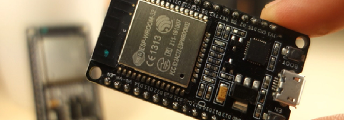
C'est Quoi Un ESP32 WROOM 32:
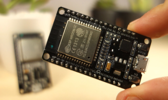
L'ESP32 WROOM 32 est un module microcontrôleur compact et puissant développé par Espressif Systems. Il intègre la puce ESP32, qui fait partie de la famille ESP (Espressif Systems Products). Le module WROOM 32 est largement utilisé dans divers systèmes embarqués et applications de l'Internet des objets (IoT) en raison de ses fonctionnalités avancées et de ses capacités.
Spécifications de l'ESP32 WROOM 32 :
L'ESP32 WROOM 32 présente les spécifications suivantes :
| Microcontrôleur | Processeur dual-core Tensilica Xtensa LX6 (fréquence d'horloge de 240 MHz). | ||
| Connectivité sans fil | Connectivité Wi-Fi intégrée 802.11 b/g/n. Connectivité Bluetooth intégrée (Bluetooth Low Energy, BLE). | ||
| Mémoire | 520 Ko de SRAM. 448 Ko de ROM (mémoire de programme). Support en option pour une mémoire flash externe SPI. | ||
| Périphériques | Périphériques Pins GPIO (Entrée/Sortie à usage général). UART, SPI, I2C, I2S, ADC, DAC. PWM (Modulation de Largeur d'Impulsion). Capteur à effet Hall. | ||
| Sécurité | Fonctionnalités de sécurité basées sur le matériel, y compris le démarrage sécurisé et le chiffrement de la mémoire flash. | ||
| Gestion de l'alimentation | Modes de faible consommation multiples pour une efficacité énergétique. Régulateur programmable pour l'alimentation du cœur. | ||
| Tension de fonctionnement | 2.2V to 3.6V. | ||
| Température de fonctionnement | "-40°C to +85°C" | ||
| Facteur de forme | Module compact avec des bords à créneaux pour une soudure facile. | ||
| Horloges et minuteries | Horloge temps réel (RTC) intégrée. Minuteries et watchdogs pour les applications sensibles au temps. | ||
| Antenne intégrée | Antenne intégrée pour la communication Wi-Fi et Bluetooth. | ||
| Certifications | Certifications FCC, CE, IC, et autres pour la conformité. | ||
| Support de développement | Support de l'IDE Arduino pour la programmation. Support MicroPython. Kit de développement logiciel (SDK) fourni par Espressif Systems. | ||
| Options d'emballage | Disponible dans différentes options d'emballage, y compris les populaires ESP32 WROOM 32D et ESP32 WROOM 32U. | ||
| Dimensions | Les dimensions typiques du module sont d'environ 18 mm x 25,5 mm. |
ESP32 WROOM 32 GPIO Pins:
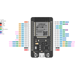
Le module ESP32 WROOM-32 dispose d'un ensemble de broches GPIO (Entrée/Sortie à Usage Général) qui peuvent être utilisées à diverses fins, notamment en tant qu'entrées/sorties numériques, entrées analogiques, modulation de largeur d'impulsion (PWM), et interfaces de communication telles que UART, I2C et SPI. La correspondance exacte des broches peut dépendre du module ESP32 spécifique ou de la carte de développement utilisée, il est donc essentiel de se référer à la documentation spécifique à votre appareil.
Voici un aperçu général des broches GPIO que l'on retrouve généralement sur le module ESP32 WROOM-32 :
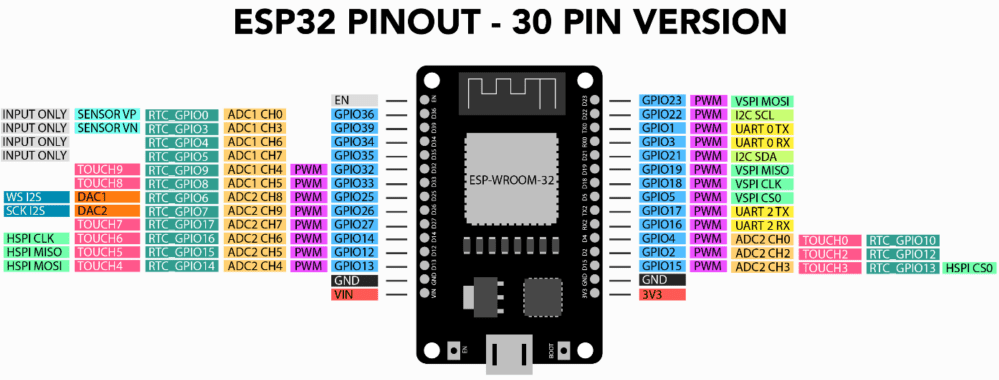
Broches numériques à usage général | GPIO 0,GPIO 1,GPIO 2,GPIO 3 GPIO 4,GPIO 5,GPIO 6,GPIO 7 GPIO 8,GPIO 9,GPIO 10,GPIO 11 GPIO 12,GPIO 13,GPIO 14,GPIO 15 GPIO 16,GPIO 17,GPIO 18,GPIO 19 GPIO 21,GPIO 22,GPIO 23,GPIO 25 GPIO 26,GPIO 27,GPIO 32,GPIO 33 GPIO 34,GPIO 35,GPIO 36,GPIO 37 GPIO 38,GPIO 39 | ||
Broches à fonction spécial | RX0, TX0: Serial communication pins (UART0). RX1, TX1: Serial communication pins (UART1). SCL, SDA: I2C communication pins. SCK, MOSI, MISO: SPI communication pins. A0: Analog input. | ||
| Broches d'alimentation | 3V3: 3.3V power output. GND: Ground. | ||
| Broches de controle | EN (Enable): Enable pin. BOOT: Boot mode selection pin. |
Broches d'Entrée/Sortie Numériques (GPIO):
Les broches GPIO sont utilisées pour les opérations d'entrée/sortie :
- GPIO 0: Numéro de pin 36
- GPIO 1: Numéro de pin 37
- GPIO 2: Numéro de pin 38
- GPIO 3: Numéro de pin 39
- GPIO 4: Numéro de pin 34
- GPIO 5: Numéro de pin 14
- GPIO 6: Numéro de pin 12
- GPIO 7: Numéro de pin 13
- GPIO 8: Numéro de pin 15
- GPIO 9: Numéro de pin 9
- GPIO 10: Numéro de pin 2
- GPIO 11: Numéro de pin 0
- GPIO 12: Numéro de pin 4
- GPIO 13: Numéro de pin 2
- GPIO 14: Numéro de pin 15
- GPIO 15: Numéro de pin 2
- GPIO 16: Numéro de pin 17
Elles peuvent être configurées comme des entrées ou des sorties selon les besoins du projet.
Entrées Analogiques:
Certaines broches peuvent être utilisées comme entrées analogiques pour mesurer des signaux de tension variables.
- ADC 0: Numéro de pin 36
- ADC 1: Numéro de pin 37
- ADC 2: Numéro de pin 38
- ADC 3: Numéro de pin 39
- ADC 4: Numéro de pin 32
- ADC 5: Numéro de pin 33
- ADC 6: Numéro de pin 34
- ADC 7: Numéro de pin 35
Modulation de Largeur d'Impulsion (PWM):
Plusieurs broches prennent en charge la modulation de largeur d'impulsion, permettant le contrôle de la vitesse des moteurs, la luminosité des LED, etc.
- PWM 0: Numéro de pin 2
- PWM 1: Numéro de pin 4
- PWM 2: Numéro de pin 5
- PWM 3: Numéro de pin 18
- PWM 4: Numéro de pin 19
- PWM 5: Numéro de pin 21
Interfaces de Communication:
UART (Universal Asynchronous Receiver-Transmitter): Les broches dédiées à l'UART facilitent la communication série.
- UART 0 (TX/RX): Numéro de pin 1 (TX), Numéro de pin 3 (RX)
- UART 1 (TX/RX): Numéro de pin 17 (TX), Numéro de pin 16 (RX)
I2C (Inter-Integrated Circuit): Des broches sont réservées pour la communication série à deux fils, permettant la connexion à des périphériques I2C.
- I2C (SDA/SCL): Numéro de pin 21 (SDA), Numéro de pin 22 (SCL)
SPI (Serial Peripheral Interface): Des broches sont attribuées à l'interface SPI pour la communication avec des dispositifs externes.
- SPI (MISO/MOSI/SCK/SS): Numéro de pin 19 (MISO), Numéro de pin 23 (MOSI), Numéro de pin 18 (SCK), Numéro de pin 5 (SS).
Note Importante :
- Certains broches GPIO ont des fonctions spéciales pendant le démarrage ou sont dédiées à des interfaces de communication spécifiques.
- Consultez la documentation spécifique de votre module ESP32 ou de votre carte de développement pour obtenir la correspondance précise des broches et leurs capacités.
Lorsque vous travaillez avec le module ESP32 WROOM-32, il est essentiel de vous référer à la fiche technique ou au manuel de référence technique fourni par Espressif Systems ou le fabricant de votre module spécifique
Programmation :
La programmation du module ESP32 WROOM-32 implique l'écriture de code dans un langage de programmation que le microcontrôleur comprend. Les langages les plus courants pour programmer l'ESP32 sont le C/C++ en utilisant l'IDE Arduino ou l'ESP-IDF (Espressif IoT Development Framework), ainsi que MicroPython. Voici un bref aperçu de la programmation de l'ESP32 WROOM-32 avec l'IDE Arduino
Arduino IDE:
Il y a plusieurs étapes à suivre pour programmer dans l'IDE Arduino ::
Installer l'IDE Arduino :
- Téléchargez et installez l'IDE Arduino depuis le site officiel d'Arduino.
Installer le Support de la Carte ESP32 :
- Ouvrez l'IDE Arduino.
- Allez dans "Fichier" -> "Préférences".
- Dans le champ "URLs de gestionnaire de cartes supplémentaires", ajoutez l'URL suivante https://dl.espressif.com/dl/package_esp32_index.json et cliquez sur "OK".
- Allez dans "Outils" -> "Carte" -> "Gestionnaire de cartes".
- Recherchez "esp32" et installez le support de carte "ESP32 par Espressif Systems".
Sélectionnez la carte ESP32 :
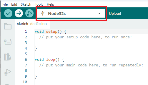
- Allez dans "Outils" -> "Carte" et sélectionnez votre carte ESP32 (par exemple, "Node32s").
Écrivez votre code et téléversez-le:
- Écrivez votre code Arduino dans l'IDE Arduino.
- Assurez-vous d'inclure les bibliothèques nécessaires pour votre projet.
- Connectez votre ESP32 à votre ordinateur via un câble USB. Sélectionnez le port COM correct sous "Outils" -> "Port."
- Cliquez sur le bouton "Téléverser" pour compiler et transférer votre code vers l'ESP32.
Note:
Après la phase de téléversement, si vous obtenez ce message :

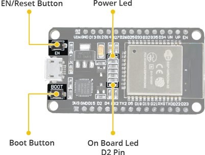
Vous avez simplement besoin d'appuyer sur le bouton de démarrage sur la carte pendant quelques secondes, puis de le relâcher, activant ainsi la transmission et l'écriture du code sur la puce de l'ESP3
.
À la fin, si le message que vous obtenez est le même que sur la photo, cela signifie que votre téléversement est complet sans problème.

MicroPython:
Thonny IDE:
Thonny est un environnement de développement intégré (IDE) Python qui peut être utilisé avec MicroPython sur l'ESP32. Voici un guide de base sur la façon d'utiliser Thonny avec l'ESP32 :"
Installer Thonny :
- Téléchargez et installez Thonny depuis le site officiel : https://thonny.org/
Installer esptool :
- Ouvrez Thonny et accédez au menu "Outils". Sélectionnez "Gérer les paquets..." Dans le Gestionnaire de paquets, recherchez "esptool" et installez-le.
Installer le micrologiciel MicroPython :
Téléchargez le micrologiciel MicroPython pour ESP32 depuis le site MicroPython https://micropython.org/download/esp32/ Connectez votre ESP32 à votre ordinateur via un câble USB.
Ouvrez Thonny et allez dans le menu "Outils". Sélectionnez "Options..." Dans la boîte de dialogue Options, allez dans l'onglet "Interpréteur". Sélectionnez "MicroPython (ESP32)" dans le menu déroulant. Cliquez sur "OK" pour fermer la boîte de dialogue Options.
Cliquez sur le bouton "Exécuter" dans Thonny pour ouvrir le REPL MicroPython.
Flasher le micrologiciel MicroPython :
Vous pouvez utiliser esptool depuis Thonny pour flasher le micrologiciel MicroPython sur votre ESP32.
Allez dans le menu "Affichage" et sélectionnez "Panneaux" -> "Shell" pour ouvrir le Shell Thonny.
Dans le Shell, utilisez la commande esptool pour flasher le micrologiciel. Par exemple : esptool.py --port /votre/port/esp --baud 460800 write_flash --flash_size=detect 0 /chemin/vers/micrologiciel-micropython.bin Remplacez /votre/port/esp par le port auquel votre ESP32 est connecté et /chemin/vers/micrologiciel-micropython.bin par le chemin du micrologiciel MicroPython que vous avez téléchargé.
Écrire et exécuter du code MicroPython :
Après le flashage, vous pouvez utiliser Thonny pour écrire et exécuter du code MicroPython sur votre ESP32. Écrivez votre script MicroPython dans l'éditeur Thonny. Utilisez le bouton "Exécuter" pour exécuter le code.
Transférer des fichiers :
- Thonny dispose d'un outil de transfert de fichiers intégré pour les appareils MicroPython.
Utilisez le menu "Fichier" pour ouvrir la boîte de dialogue "Transférer des fichiers vers l'appareil". Utilisez cette boîte de dialogue pour transférer des fichiers Python sur votre ESP32."
Conclusion:
En conclusion, l'ESP32 WROOM-32 est un module microcontrôleur polyvalent et riche en fonctionnalités qui a gagné en popularité au sein des communautés des créateurs et de l'IoT. Sa combinaison de performances, d'options de connectivité et d'un écosystème de développement robuste en fait un choix convaincant pour une grande variété de projets.







95 Commentaire (s)
Way cool! Some extremely valid points! I appreciate you penning this article plus the rest of the site is also very good.
I visited many web sites but the audio quality for audio songs current at this site is really superb.
I need to to thank you for this great read!! I certainly loved every bit of it. I have you saved as a favorite to look at new stuff you
I’ll right away grab your rss feed as I can’t find your email subscription hyperlink or newsletter service. Do you have any? Please permit me recognize in order that I may subscribe. Thanks.
I want to to thank you for this very good read!! I definitely enjoyed every little bit of it. I have got you book marked to look at new stuff you
Hi, I do think this is a great website. I stumbledupon it ;) I will come back yet again since i have bookmarked it. Money and freedom is the greatest way to change, may you be rich and continue to help others.
I am sure this article has touched all the internet visitors, its really really pleasant article on building up new weblog.
These are truly fantastic ideas in concerning blogging. You have touched some pleasant points here. Any way keep up wrinting.
That is really fascinating, You are an excessively professional blogger. I have joined your feed and stay up for seeking more of your fantastic post. Additionally, I have shared your web site in my social networks!
I am sure this piece of writing has touched all the internet viewers, its really really fastidious article on building up new web site.
I am sure this post has touched all the internet visitors, its really really nice post on building up new website.
Quality articles is the main to be a focus for the visitors to pay a quick visit the web page, that\'s what this web site is providing.
It\'s very trouble-free to find out any matter on web as compared to books, as I found this article at this website.
I used to be recommended this website by way of my cousin. I\'m now not positive whether this submit is written through him as no one else understand such unique about my trouble. You are wonderful! Thanks!
I had a great experience with CredVeda Financial Services. Their website is very user-friendly, and the entire loan process is hassle-free. I was able to check my eligibility, calculate EMIs, and submit documents online without visiting any office. The staff responded quickly to my queries and kept me updated about my loan status. The approval came faster than expected, and the amount was credited the same day. Excellent experience overall!
Ahaa, its good dialogue about this article here at this blog, I have read all that, so at this time me also commenting here.
These are actually fantastic ideas in concerning blogging. You have touched some nice factors here. Any way keep up wrinting.
Greetings! Very helpful advice within this article! It\'s the little changes that produce the largest changes. Thanks for sharing!
I’ll immediately grasp your rss feed as I can not to find your e-mail subscription hyperlink or newsletter service. Do you have any? Kindly allow me know in order that I may subscribe. Thanks.
San Francisco has made it clear they plan to run the ball.
I\'ll right away clutch your rss as I can not in finding your e-mail subscription hyperlink or newsletter service. Do you have any? Kindly allow me know so that I could subscribe. Thanks.
I simply could not leave your site before suggesting that I really loved the standard info an individual supply in your visitors? Is gonna be again often to check out new posts
I am sure this article has touched all the internet users, its really really pleasant article on building up new webpage.
Hi, yeah this piece of writing is actually pleasant and I have learned lot of things from it regarding blogging. thanks.
Well written and insightful post! Your Explanation was spot-on and easy to follow. Excited for more!
This is the perfect website for anyone who really wants to understand this topic. You realize a whole lot its almost tough to argue with you. Excellent stuff, just wonderful!
We’re the SEO company businesses worldwide trust to rise above digital noise and achieve real results. Our performance-driven strategies combine deep technical expertise with a data-backed understanding of global markets — helping your brand stand out, attract the right audience, and grow with measurable success.
This blog shares good insight on reddy book betting.\r\nThe information looks genuine and useful.
Not many blogs talk properly about Call girls in Patna, so this one stands out.
Thank you for share a amazing blog i like it.
The blog feels genuine for escort in Udaipur.
If you care about authenticity, go for Lab certified gemstones Sahakara Nagar.
Explore the profound effects of our DMT Vape Pen, designed for those seeking a unique and transformative experience. This pen offers a convenient way to access DMT’s powerful insights and creativity, all in a user-friendly format.\r\nhttps://expresspsychedelic.com/product/dmt-vape-pen/
https://camseafoodworldwide.com/products/snails-inquiry-whatsap-us-237-670819930\r\nhttps://camseafoodworldwide.com/products/maize-inquiry-whatsap-us-237-670819930\r\nhttps://camseafoodworldwide.com/products/fresh-black-snapper-fish\r\nhttps://camseafoodworldwide.com/products/tuna\r\nhttps://camseafoodworldwide.com/products/stock-fish\r\nhttps://camseafoodworldwide.com/products/rice\r\nhttps://camseafoodworldwide.com/products/palm-oil-inquiry-whatsap-us-237-670819930\r\nhttps://camseafoodworldwide.com/products/crayfish-inquiry-whatsap-us-237-670819930\r\nhttps://camseafoodworldwide.com/products/yam-inquiry-whatsap-us-237-670819930\r\nhttps://camseafoodworldwide.com/products/watermelon-inquiry-whatsap-us-237-670819930\r\nhttps://camseafoodworldwide.com/products/cycad\r\nhttps://camseafoodworldwide.com/products/titus-fish-inquiry-whatsap-us-237-670819930\r\nhttps://camseafoodworldwide.com/products/dry-sawa-fish-inquiry-whatsap-us-237-670819930https://camseafoodworldwide.com/products/barracuda-inquiry-whatsap-us-237-670819930\r\nhttps://camseafoodworldwide.com/products/shiny-nose-bladder-inquiry-whatsap-us-237-670819930\r\nhttps://camseafoodworldwide.com/products/sunflower-oil-inquiry-whatsap-us-237-670819930\r\nhttps://camseafoodworldwide.com/products/palm-oil-inquiry-whatsap-us-237-670819930\r\nhttps://camseafoodworldwide.com/products/banana-inquiry-whatsap-us-237-670819930\r\nhttps://camseafoodworldwide.com/products/garlic\r\nhttps://camseafoodworldwide.com/products/argan-oil-inquiry-whatsap-us-237-670819930\r\nhttps://camseafoodworldwide.com/products/ginger-inquiry-whatsap-us-237-670819930\r\nhttps://camseafoodworldwide.com/products/frozen-chicken-inquiry-whatsap-us-237-670819930\r\nhttps://camseafoodworldwide.com/products/onions-inquiry-whatsap-us-237-670819930\r\nhttps://camseafoodworldwide.com/products/dried-pepper\r\nhttps://camseafoodworldwide.com/products/coffee\r\nhttps://camseafoodworldwide.com/products/cotton\r\nhttps://camseafoodworldwide.com/products/cashew-nuts\r\nhttps://camseafoodworldwide.com/products/tea\r\nhttps://camseafoodworldwide.com/products/tobacco\r\nhttps://camseafoodworldwide.com/products/cloves\r\nhttps://camseafoodworldwide.com/products/cocoa-seeds-inquiry-whatsap-us-237-670819930\r\nhttps://camseafoodworldwide.com/products/rbd-palm-olein-cp10\r\nhttps://camseafoodworldwide.com/products/avocado\r\nhttps://camseafoodworldwide.com/products/peanut\r\nhttps://camseafoodworldwide.com/products/bitter-cola-inquiry-whatsap-us-237-670819930\r\nhttps://camseafoodworldwide.com/products/cucumber\r\nhttps://camseafoodworldwide.com/products/country-onion-inquiry-whatsap-us-237-670819930\r\nhttps://camseafoodworldwide.com/products/palm-nuts-inquiry-whatsap-us-237-670819930\r\nhttps://camseafoodworldwide.com/products/white-pepper\r\nhttps://camseafoodworldwide.com/products/black-pepper\r\nhttps://camseafoodworldwide.com/products/coconut\r\nhttps://camseafoodworldwide.com/products/soya-beans\r\nhttps://camseafoodworldwide.com/products/sweet-potatoes\r\nhttps://camseafoodworldwide.com/products/plantain\r\nhttps://camseafoodworldwide.com/products/stock-fish\r\n\r\nhttps://camseafoodworldwide.com/products/pineapple-inquiry-whatsap-us-237-670819930\r\nhttps://camseafoodworldwide.com/products/irish-potatoes-inquiry-whatsap-us-237-670819930\r\nhttps://camseafoodworldwide.com/products/snails-inquiry-whatsap-us-237-670819930\r\nhttps://camseafoodworldwide.com/products/sugarcane-inquiry-whatsap-us-237-670819930\r\nhttps://camseafoodworldwide.com/products/garri-inquiry-whatsap-us-237-670819930\r\nhttps://camseafoodworldwide.com/products/cocoyam-inquiry-whatsap-us-237-670819930\r\nhttps://camseafoodworldwide.com/products/cocoyam-inquiry-whatsap-us-237-670819930
https://camseafoodworldwide.com/products/snails-inquiry-whatsap-us-237-670819930\r\nhttps://camseafoodworldwide.com/products/maize-inquiry-whatsap-us-237-670819930\r\nhttps://camseafoodworldwide.com/products/fresh-black-snapper-fish\r\nhttps://camseafoodworldwide.com/products/tuna\r\nhttps://camseafoodworldwide.com/products/stock-fish\r\nhttps://camseafoodworldwide.com/products/rice\r\nhttps://camseafoodworldwide.com/products/palm-oil-inquiry-whatsap-us-237-670819930\r\nhttps://camseafoodworldwide.com/products/crayfish-inquiry-whatsap-us-237-670819930\r\nhttps://camseafoodworldwide.com/products/yam-inquiry-whatsap-us-237-670819930\r\nhttps://camseafoodworldwide.com/products/watermelon-inquiry-whatsap-us-237-670819930\r\nhttps://camseafoodworldwide.com/products/cycad\r\nhttps://camseafoodworldwide.com/products/titus-fish-inquiry-whatsap-us-237-670819930\r\nhttps://camseafoodworldwide.com/products/dry-sawa-fish-inquiry-whatsap-us-237-670819930https://camseafoodworldwide.com/products/barracuda-inquiry-whatsap-us-237-670819930\r\nhttps://camseafoodworldwide.com/products/shiny-nose-bladder-inquiry-whatsap-us-237-670819930\r\nhttps://camseafoodworldwide.com/products/sunflower-oil-inquiry-whatsap-us-237-670819930\r\nhttps://camseafoodworldwide.com/products/palm-oil-inquiry-whatsap-us-237-670819930\r\nhttps://camseafoodworldwide.com/products/banana-inquiry-whatsap-us-237-670819930\r\nhttps://camseafoodworldwide.com/products/garlic\r\nhttps://camseafoodworldwide.com/products/argan-oil-inquiry-whatsap-us-237-670819930\r\nhttps://camseafoodworldwide.com/products/ginger-inquiry-whatsap-us-237-670819930\r\nhttps://camseafoodworldwide.com/products/frozen-chicken-inquiry-whatsap-us-237-670819930\r\nhttps://camseafoodworldwide.com/products/onions-inquiry-whatsap-us-237-670819930\r\nhttps://camseafoodworldwide.com/products/dried-pepper\r\nhttps://camseafoodworldwide.com/products/coffee\r\nhttps://camseafoodworldwide.com/products/cotton\r\nhttps://camseafoodworldwide.com/products/cashew-nuts\r\nhttps://camseafoodworldwide.com/products/tea\r\nhttps://camseafoodworldwide.com/products/tobacco\r\nhttps://camseafoodworldwide.com/products/cloves\r\nhttps://camseafoodworldwide.com/products/cocoa-seeds-inquiry-whatsap-us-237-670819930\r\nhttps://camseafoodworldwide.com/products/rbd-palm-olein-cp10\r\nhttps://camseafoodworldwide.com/products/avocado\r\nhttps://camseafoodworldwide.com/products/peanut\r\nhttps://camseafoodworldwide.com/products/bitter-cola-inquiry-whatsap-us-237-670819930\r\nhttps://camseafoodworldwide.com/products/cucumber\r\nhttps://camseafoodworldwide.com/products/country-onion-inquiry-whatsap-us-237-670819930\r\nhttps://camseafoodworldwide.com/products/palm-nuts-inquiry-whatsap-us-237-670819930\r\nhttps://camseafoodworldwide.com/products/white-pepper\r\nhttps://camseafoodworldwide.com/products/black-pepper\r\nhttps://camseafoodworldwide.com/products/coconut\r\nhttps://camseafoodworldwide.com/products/soya-beans\r\nhttps://camseafoodworldwide.com/products/sweet-potatoes\r\nhttps://camseafoodworldwide.com/products/plantain\r\nhttps://camseafoodworldwide.com/products/stock-fish\r\n\r\nhttps://camseafoodworldwide.com/products/pineapple-inquiry-whatsap-us-237-670819930\r\nhttps://camseafoodworldwide.com/products/irish-potatoes-inquiry-whatsap-us-237-670819930\r\nhttps://camseafoodworldwide.com/products/snails-inquiry-whatsap-us-237-670819930\r\nhttps://camseafoodworldwide.com/products/sugarcane-inquiry-whatsap-us-237-670819930\r\nhttps://camseafoodworldwide.com/products/garri-inquiry-whatsap-us-237-670819930\r\nhttps://camseafoodworldwide.com/products/cocoyam-inquiry-whatsap-us-237-670819930\r\nhttps://camseafoodworldwide.com/products/cocoyam-inquiry-whatsap-us-237-670819930
https://camseafoodworldwide.com/products/snails-inquiry-whatsap-us-237-670819930\r\nhttps://camseafoodworldwide.com/products/maize-inquiry-whatsap-us-237-670819930\r\nhttps://camseafoodworldwide.com/products/fresh-black-snapper-fish\r\nhttps://camseafoodworldwide.com/products/tuna\r\nhttps://camseafoodworldwide.com/products/stock-fish\r\nhttps://camseafoodworldwide.com/products/rice\r\nhttps://camseafoodworldwide.com/products/palm-oil-inquiry-whatsap-us-237-670819930\r\nhttps://camseafoodworldwide.com/products/crayfish-inquiry-whatsap-us-237-670819930\r\nhttps://camseafoodworldwide.com/products/yam-inquiry-whatsap-us-237-670819930\r\nhttps://camseafoodworldwide.com/products/watermelon-inquiry-whatsap-us-237-670819930\r\nhttps://camseafoodworldwide.com/products/cycad\r\nhttps://camseafoodworldwide.com/products/titus-fish-inquiry-whatsap-us-237-670819930\r\nhttps://camseafoodworldwide.com/products/dry-sawa-fish-inquiry-whatsap-us-237-670819930https://camseafoodworldwide.com/products/barracuda-inquiry-whatsap-us-237-670819930\r\nhttps://camseafoodworldwide.com/products/shiny-nose-bladder-inquiry-whatsap-us-237-670819930\r\nhttps://camseafoodworldwide.com/products/sunflower-oil-inquiry-whatsap-us-237-670819930\r\nhttps://camseafoodworldwide.com/products/palm-oil-inquiry-whatsap-us-237-670819930\r\nhttps://camseafoodworldwide.com/products/banana-inquiry-whatsap-us-237-670819930\r\nhttps://camseafoodworldwide.com/products/garlic\r\nhttps://camseafoodworldwide.com/products/argan-oil-inquiry-whatsap-us-237-670819930\r\nhttps://camseafoodworldwide.com/products/ginger-inquiry-whatsap-us-237-670819930\r\nhttps://camseafoodworldwide.com/products/frozen-chicken-inquiry-whatsap-us-237-670819930\r\nhttps://camseafoodworldwide.com/products/onions-inquiry-whatsap-us-237-670819930\r\nhttps://camseafoodworldwide.com/products/dried-pepper\r\nhttps://camseafoodworldwide.com/products/coffee\r\nhttps://camseafoodworldwide.com/products/cotton\r\nhttps://camseafoodworldwide.com/products/cashew-nuts\r\nhttps://camseafoodworldwide.com/products/tea\r\nhttps://camseafoodworldwide.com/products/tobacco\r\nhttps://camseafoodworldwide.com/products/cloves\r\nhttps://camseafoodworldwide.com/products/cocoa-seeds-inquiry-whatsap-us-237-670819930\r\nhttps://camseafoodworldwide.com/products/rbd-palm-olein-cp10\r\nhttps://camseafoodworldwide.com/products/avocado\r\nhttps://camseafoodworldwide.com/products/peanut\r\nhttps://camseafoodworldwide.com/products/bitter-cola-inquiry-whatsap-us-237-670819930\r\nhttps://camseafoodworldwide.com/products/cucumber\r\nhttps://camseafoodworldwide.com/products/country-onion-inquiry-whatsap-us-237-670819930\r\nhttps://camseafoodworldwide.com/products/palm-nuts-inquiry-whatsap-us-237-670819930\r\nhttps://camseafoodworldwide.com/products/white-pepper\r\nhttps://camseafoodworldwide.com/products/black-pepper\r\nhttps://camseafoodworldwide.com/products/coconut\r\nhttps://camseafoodworldwide.com/products/soya-beans\r\nhttps://camseafoodworldwide.com/products/sweet-potatoes\r\nhttps://camseafoodworldwide.com/products/plantain\r\nhttps://camseafoodworldwide.com/products/stock-fish\r\n\r\nhttps://camseafoodworldwide.com/products/pineapple-inquiry-whatsap-us-237-670819930\r\nhttps://camseafoodworldwide.com/products/irish-potatoes-inquiry-whatsap-us-237-670819930\r\nhttps://camseafoodworldwide.com/products/snails-inquiry-whatsap-us-237-670819930\r\nhttps://camseafoodworldwide.com/products/sugarcane-inquiry-whatsap-us-237-670819930\r\nhttps://camseafoodworldwide.com/products/garri-inquiry-whatsap-us-237-670819930\r\nhttps://camseafoodworldwide.com/products/cocoyam-inquiry-whatsap-us-237-670819930\r\nhttps://camseafoodworldwide.com/products/cocoyam-inquiry-whatsap-us-237-670819930
https://camseafoodworldwide.com/products/snails-inquiry-whatsap-us-237-670819930\r\nhttps://camseafoodworldwide.com/products/maize-inquiry-whatsap-us-237-670819930\r\nhttps://camseafoodworldwide.com/products/fresh-black-snapper-fish\r\nhttps://camseafoodworldwide.com/products/tuna\r\nhttps://camseafoodworldwide.com/products/stock-fish\r\nhttps://camseafoodworldwide.com/products/rice\r\nhttps://camseafoodworldwide.com/products/palm-oil-inquiry-whatsap-us-237-670819930\r\nhttps://camseafoodworldwide.com/products/crayfish-inquiry-whatsap-us-237-670819930\r\nhttps://camseafoodworldwide.com/products/yam-inquiry-whatsap-us-237-670819930\r\nhttps://camseafoodworldwide.com/products/watermelon-inquiry-whatsap-us-237-670819930\r\nhttps://camseafoodworldwide.com/products/cycad\r\nhttps://camseafoodworldwide.com/products/titus-fish-inquiry-whatsap-us-237-670819930\r\nhttps://camseafoodworldwide.com/products/dry-sawa-fish-inquiry-whatsap-us-237-670819930https://camseafoodworldwide.com/products/barracuda-inquiry-whatsap-us-237-670819930\r\nhttps://camseafoodworldwide.com/products/shiny-nose-bladder-inquiry-whatsap-us-237-670819930\r\nhttps://camseafoodworldwide.com/products/sunflower-oil-inquiry-whatsap-us-237-670819930\r\nhttps://camseafoodworldwide.com/products/palm-oil-inquiry-whatsap-us-237-670819930\r\nhttps://camseafoodworldwide.com/products/banana-inquiry-whatsap-us-237-670819930\r\nhttps://camseafoodworldwide.com/products/garlic\r\nhttps://camseafoodworldwide.com/products/argan-oil-inquiry-whatsap-us-237-670819930\r\nhttps://camseafoodworldwide.com/products/ginger-inquiry-whatsap-us-237-670819930\r\nhttps://camseafoodworldwide.com/products/frozen-chicken-inquiry-whatsap-us-237-670819930\r\nhttps://camseafoodworldwide.com/products/onions-inquiry-whatsap-us-237-670819930\r\nhttps://camseafoodworldwide.com/products/dried-pepper\r\nhttps://camseafoodworldwide.com/products/coffee\r\nhttps://camseafoodworldwide.com/products/cotton\r\nhttps://camseafoodworldwide.com/products/cashew-nuts\r\nhttps://camseafoodworldwide.com/products/tea\r\nhttps://camseafoodworldwide.com/products/tobacco\r\nhttps://camseafoodworldwide.com/products/cloves\r\nhttps://camseafoodworldwide.com/products/cocoa-seeds-inquiry-whatsap-us-237-670819930\r\nhttps://camseafoodworldwide.com/products/rbd-palm-olein-cp10\r\nhttps://camseafoodworldwide.com/products/avocado\r\nhttps://camseafoodworldwide.com/products/peanut\r\nhttps://camseafoodworldwide.com/products/bitter-cola-inquiry-whatsap-us-237-670819930\r\nhttps://camseafoodworldwide.com/products/cucumber\r\nhttps://camseafoodworldwide.com/products/country-onion-inquiry-whatsap-us-237-670819930\r\nhttps://camseafoodworldwide.com/products/palm-nuts-inquiry-whatsap-us-237-670819930\r\nhttps://camseafoodworldwide.com/products/white-pepper\r\nhttps://camseafoodworldwide.com/products/black-pepper\r\nhttps://camseafoodworldwide.com/products/coconut\r\nhttps://camseafoodworldwide.com/products/soya-beans\r\nhttps://camseafoodworldwide.com/products/sweet-potatoes\r\nhttps://camseafoodworldwide.com/products/plantain\r\nhttps://camseafoodworldwide.com/products/stock-fish\r\n\r\nhttps://camseafoodworldwide.com/products/pineapple-inquiry-whatsap-us-237-670819930\r\nhttps://camseafoodworldwide.com/products/irish-potatoes-inquiry-whatsap-us-237-670819930\r\nhttps://camseafoodworldwide.com/products/snails-inquiry-whatsap-us-237-670819930\r\nhttps://camseafoodworldwide.com/products/sugarcane-inquiry-whatsap-us-237-670819930\r\nhttps://camseafoodworldwide.com/products/garri-inquiry-whatsap-us-237-670819930\r\nhttps://camseafoodworldwide.com/products/cocoyam-inquiry-whatsap-us-237-670819930\r\nhttps://camseafoodworldwide.com/products/cocoyam-inquiry-whatsap-us-237-670819930
https://camseafoodworldwide.com/products/snails-inquiry-whatsap-us-237-670819930\r\nhttps://camseafoodworldwide.com/products/maize-inquiry-whatsap-us-237-670819930\r\nhttps://camseafoodworldwide.com/products/fresh-black-snapper-fish\r\nhttps://camseafoodworldwide.com/products/tuna\r\nhttps://camseafoodworldwide.com/products/stock-fish\r\nhttps://camseafoodworldwide.com/products/rice\r\nhttps://camseafoodworldwide.com/products/palm-oil-inquiry-whatsap-us-237-670819930\r\nhttps://camseafoodworldwide.com/products/crayfish-inquiry-whatsap-us-237-670819930\r\nhttps://camseafoodworldwide.com/products/yam-inquiry-whatsap-us-237-670819930\r\nhttps://camseafoodworldwide.com/products/watermelon-inquiry-whatsap-us-237-670819930\r\nhttps://camseafoodworldwide.com/products/cycad\r\nhttps://camseafoodworldwide.com/products/titus-fish-inquiry-whatsap-us-237-670819930\r\nhttps://camseafoodworldwide.com/products/dry-sawa-fish-inquiry-whatsap-us-237-670819930https://camseafoodworldwide.com/products/barracuda-inquiry-whatsap-us-237-670819930\r\nhttps://camseafoodworldwide.com/products/shiny-nose-bladder-inquiry-whatsap-us-237-670819930\r\nhttps://camseafoodworldwide.com/products/sunflower-oil-inquiry-whatsap-us-237-670819930\r\nhttps://camseafoodworldwide.com/products/palm-oil-inquiry-whatsap-us-237-670819930\r\nhttps://camseafoodworldwide.com/products/banana-inquiry-whatsap-us-237-670819930\r\nhttps://camseafoodworldwide.com/products/garlic\r\nhttps://camseafoodworldwide.com/products/argan-oil-inquiry-whatsap-us-237-670819930\r\nhttps://camseafoodworldwide.com/products/ginger-inquiry-whatsap-us-237-670819930\r\nhttps://camseafoodworldwide.com/products/frozen-chicken-inquiry-whatsap-us-237-670819930\r\nhttps://camseafoodworldwide.com/products/onions-inquiry-whatsap-us-237-670819930\r\nhttps://camseafoodworldwide.com/products/dried-pepper\r\nhttps://camseafoodworldwide.com/products/coffee\r\nhttps://camseafoodworldwide.com/products/cotton\r\nhttps://camseafoodworldwide.com/products/cashew-nuts\r\nhttps://camseafoodworldwide.com/products/tea\r\nhttps://camseafoodworldwide.com/products/tobacco\r\nhttps://camseafoodworldwide.com/products/cloves\r\nhttps://camseafoodworldwide.com/products/cocoa-seeds-inquiry-whatsap-us-237-670819930\r\nhttps://camseafoodworldwide.com/products/rbd-palm-olein-cp10\r\nhttps://camseafoodworldwide.com/products/avocado\r\nhttps://camseafoodworldwide.com/products/peanut\r\nhttps://camseafoodworldwide.com/products/bitter-cola-inquiry-whatsap-us-237-670819930\r\nhttps://camseafoodworldwide.com/products/cucumber\r\nhttps://camseafoodworldwide.com/products/country-onion-inquiry-whatsap-us-237-670819930\r\nhttps://camseafoodworldwide.com/products/palm-nuts-inquiry-whatsap-us-237-670819930\r\nhttps://camseafoodworldwide.com/products/white-pepper\r\nhttps://camseafoodworldwide.com/products/black-pepper\r\nhttps://camseafoodworldwide.com/products/coconut\r\nhttps://camseafoodworldwide.com/products/soya-beans\r\nhttps://camseafoodworldwide.com/products/sweet-potatoes\r\nhttps://camseafoodworldwide.com/products/plantain\r\nhttps://camseafoodworldwide.com/products/stock-fish\r\n\r\nhttps://camseafoodworldwide.com/products/pineapple-inquiry-whatsap-us-237-670819930\r\nhttps://camseafoodworldwide.com/products/irish-potatoes-inquiry-whatsap-us-237-670819930\r\nhttps://camseafoodworldwide.com/products/snails-inquiry-whatsap-us-237-670819930\r\nhttps://camseafoodworldwide.com/products/sugarcane-inquiry-whatsap-us-237-670819930\r\nhttps://camseafoodworldwide.com/products/garri-inquiry-whatsap-us-237-670819930\r\nhttps://camseafoodworldwide.com/products/cocoyam-inquiry-whatsap-us-237-670819930\r\nhttps://camseafoodworldwide.com/products/cocoyam-inquiry-whatsap-us-237-670819930
Helpful overview of 99exch new id process.\r\nThis post cleared many doubts.
Through e Kalyan Jharkhand Scholarship, the state government supports students financially for education. The online portal helps avoid middlemen and ensures direct benefit transfer. Students can easily log in, update details, and track their scholarship progress anytime.
Greetings everyone! As a Hot Lady, I am SNETHI ROY pleased to offer you high-class Kolkata Call Girls and Hyderabad Escorts. Our agency is authentic and we provide the most desirable and alluring Hyderabad Escorts Service. Our services are available 24/7, 365 days a year with safety and security as our top priority. Our girls are accommodating, cooperative, and have a friendly nature. Come and experience the beauty of our Lucknow Call Girls.\r\n\r\nhttps://www.sexyescorts.in\r\nhttps://www.hotescorts.in\r\nhttps://www.hyderabadescortgirls.in
Thanks for sharing this. A good Indore call girl service really depends on communication and professionalism, which you’ve explained nicely.
<a href="https://tucibipinkmktelgram.uk/"rel="dofollow">buy trankimazin online</a>\r\n<a href="https://tucibipinkmktelgram.uk/"rel="dofollow"> where to buy promethazine in UK</a>\r\n<a href="https://tucibipinkmktelgram.uk/"rel="dofollow">Buy promethazine 25mg online</a>\r\n<a href="https://tucibipinkmktelgram.uk/"rel="dofollow">smartwhip </a>\r\n<a href="https://tucibipinkmktelgram.uk/"rel="dofollow">smart whips in UK</a>\r\n<a href="https://tucibipinkmktelgram.uk/"rel="dofollow">where can i get smartwhip in UK </a>\r\n<a href="https://tucibipinkmktelgram.uk/"rel="dofollow">smartwhip uk</a>\r\n<a href="https://tucibipinkmktelgram.uk/"rel="dofollow">smartwhip sliver<a>\r\n<a href="https://tucibipinkmktelgram.uk/"rel="dofollow">buy mdma molly</a>\r\n<a href="https://tucibipinkmktelgram.uk/"rel="dofollow">smartwhip London</a>\r\n<a href="https://tucibipinkmktelgram.uk/"rel="dofollow">smartwhip delivery</a>\r\n<a href="https://tucibipinkmktelgram.uk/"rel="dofollow">buy cheap prescribe drugs in UK</a>\r\n<a href="https://tucibipinkmktelgram.uk/"rel="dofollow">how to order for pregabalin 300mg</a>\r\n<a href="https://tucibipinkmktelgram.uk/"rel="dofollow">buy paderyl online</a>\r\n<a href="https://tucibipinkmktelgram.uk/"rel="dofollow">pregabalin tablets /a>\r\n<a href="https://tucibipinkmktelgram.uk/"rel="dofollow"> pure cocaine vendors online</a>\r\n<a href="https://tucibipinkmktelgram.uk/"rel="dofollow">how can i get ketamine online/a>\r\n<a href="https://tucibipinkmktelgram.uk/"rel="dofollow"buy syrup stilpane in UK</a><a href="https://tucibipinkmktelgram.uk/"rel="dofollow">buy ketamine online in UK</a> # what-apps(+447762291334)\r\n<a href="https://tucibipinkmktelgram.uk/"rel="dofollow">pink oxycodone</a>\r\n<a href="https://tucibipinkmktelgram.uk/"rel="dofollow">buy alprazolam uk</a>\r\n<a href="https://tucibipinkmktelgram.uk/"rel="dofollow">Buy promethazine 25mg online</a>\r\n<a href="https://tucibipinkmktelgram.uk/"rel="dofollow">buy scripts M523 OXY 15s</a>\r\n<a href="https://tucibipinkmktelgram.uk/"rel="dofollow">order rp30 30mg</a>\r\n<a href="https://tucibipinkmktelgram.uk/"rel="dofollow">buy liquid lsd in UK </a>\r\n<a href="https://tucibipinkmktelgram.uk/"rel="dofollow">where to buy dmt online</a>\r\n<a href="https://tucibipinkmktelgram.uk/"rel="dofollow">codeine phosphate tablets<a>\r\n<a href="https://tucibipinkmktelgram.uk/"rel="dofollow">buy zopiclone online</a>\r\n<a href="https://tucibipinkmktelgram.uk/"rel="dofollow">where to get lyrica in UK</a>\r\n<a href="https://tucibipinkmktelgram.uk/"rel="dofollow">how can i order codipront online</a>\r\n<a href="https://tucibipinkmktelgram.uk/"rel="dofollow">where to purchase rohypnol flunitrazepam uk</a>\r\n<a href="https://tucibipinkmktelgram.uk/"rel="dofollow">buy ritalin SR </a>\r\n<a href="https://tucibipinkmktelgram.uk/"rel="dofollow">seresta 50mg</a>\r\n<a href="https://tucibipinkmktelgram.uk/"rel="dofollow">buy cheap toseina online/a>\r\n<a href="https://tucibipinkmktelgram.uk/"rel="dofollow"> heroine in UK</a>\r\n<a href="https://tucibipinkmktelgram.uk/"rel="dofollow">methadone 40mg/a>\r\n<a href="https://tucibipinkmktelgram.uk/"rel="dofollow">dramadol </a><a href="https://tucibipinkmktelgram.uk/"rel="dofollow">diazepam uk</a> # what-apps(+447762291334)<a href="https://tucibipinkmktelgram.uk/"rel="dofollow">buy trankimazin online</a>\r\n<a href="https://tucibipinkmktelgram.uk/"rel="dofollow"> how to order tramadol tablets 200mg</a>\r\n<a href="https://tucibipinkmktelgram.uk/"rel="dofollow">buy phenergan online</a>\r\n<a href="https://tucibipinkmktelgram.uk/"rel="dofollow">where to order skenan 10mg in UK </a>\r\n<a href="https://tucibipinkmktelgram.uk/"rel="dofollow">order rp30 30mg</a>\r\n<a href="https://tucibipinkmktelgram.uk/"rel="dofollow">buy liquid lsd in UK </a>\r\n<a href="https://tucibipinkmktelgram.uk/"rel="dofollow">where to buy dmt online</a>\r\n<a href="https://tucibipinkmktelgram.uk/"rel="dofollow">buy liquid ketamine<a>\r\n<a href="https://tucibipinkmktelgram.uk/"rel="dofollow">buy zopiclone online</a>\r\n<a href="https://tucibipinkmktelgram.uk/"rel="dofollow">where to order skenan 10mg in UK London</a>\r\n<a href="https://tucibipinkmktelgram.uk/"rel="dofollow">pure coke 98%</a>\r\n<a href="https://tucibipinkmktelgram.uk/"rel="dofollow">buy tranxene 20mg online</a>\r\n<a href="https://tucibipinkmktelgram.uk/"rel="dofollow">syrop promethazine</a>\r\n<a href="https://tucibipinkmktelgram.uk/"rel="dofollow">buy paderyl online</a>\r\n<a href="https://tucibipinkmktelgram.uk/"rel="dofollow">adderall xr /a>\r\n<a href="https://tucibipinkmktelgram.uk/"rel="dofollow"> how can i order tryasol </a>\r\n<a href="https://tucibipinkmktelgram.uk/"rel="dofollow">where to purchase actithiol online/a>\r\n<a href="https://tucibipinkmktelgram.uk/"rel="dofollow"buy syrup stilpane in UK</a><a href="https://tucibipinkmktelgram.uk/"rel="dofollow">diazepam uk</a> # what-apps(+447762291334)\r\n<a href="https://tucibipinkmktelgram.uk/"rel="dofollow"></a>\r\n<a href="https://tucibipinkmktelgram.uk/"rel="dofollow">buy alprazolam uk</a>\r\n<a href="https://tucibipinkmktelgram.uk/"rel="dofollow">buy phenergan online</a>\r\n<a href="https://tucibipinkmktelgram.uk/"rel="dofollow">smartwhip </a>\r\n<a href="https://tucibipinkmktelgram.uk/"rel="dofollow">smart whips in UK</a>\r\n<a href="https://tucibipinkmktelgram.uk/"rel="dofollow">where can i get smartwhip in UK </a>\r\n<a href="https://tucibipinkmktelgram.uk/"rel="dofollow">where to buy dmt online</a>\r\n<a href="https://tucibipinkmktelgram.uk/"rel="dofollow">buy liquid ketamine<a>\r\n<a href="https://tucibipinkmktelgram.uk/"rel="dofollow">buy zopiclone online</a>\r\n<a href="https://tucibipinkmktelgram.uk/"rel="dofollow">smartwhip London</a>\r\n<a href="https://tucibipinkmktelgram.uk/"rel="dofollow">pure coke 98%</a>\r\n<a href="https://tucibipinkmktelgram.uk/"rel="dofollow">buy tranxene 20mg online</a>\r\n<a href="https://tucibipinkmktelgram.uk/"rel="dofollow">syrop promethazine</a>\r\n<a href="https://tucibipinkmktelgram.uk/"rel="dofollow">buy paderyl online</a>\r\n<a href="https://tucibipinkmktelgram.uk/"rel="dofollow">adderall xr /a>\r\n<a href="https://tucibipinkmktelgram.uk/"rel="dofollow"> how can i order tryasol </a>\r\n<a href="https://tucibipinkmktelgram.uk/"rel="dofollow">where to purchase actithiol online/a>\r\n<a href="https://tucibipinkmktelgram.uk/"rel="dofollow"buy syrup stilpane in UK</a><a href="https://tucibipinkmktelgram.uk/"rel="dofollow">diazepam uk</a> # what-apps(+447762291334)\r\n\r\n<a href="https://tucibipinkmktelgram.uk/"rel="dofollow">buy trankimazin online</a>\r\n<a href="https://tucibipinkmktelgram.uk/"rel="dofollow"> how to order tramadol tablets 200mg</a>\r\n<a href="https://tucibipinkmktelgram.uk/"rel="dofollow">buy phenergan online</a>\r\n<a href="https://tucibipinkmktelgram.uk/"rel="dofollow">smartwhip </a>\r\n<a href="https://tucibipinkmktelgram.uk/"rel="dofollow">smart whips in UK</a>\r\n<a href="https://tucibipinkmktelgram.uk/"rel="dofollow">where can i get smartwhip in UK </a>\r\n<a href="https://tucibipinkmktelgram.uk/"rel="dofollow">smartwhip uk</a>\r\n<a href="https://tucibipinkmktelgram.uk/"rel="dofollow">smartwhip sliver<a>\r\n<a href="https://tucibipinkmktelgram.uk/"rel="dofollow">buy zopiclone online</a>\r\n<a href="https://tucibipinkmktelgram.uk/"rel="dofollow">smartwhip London</a>\r\n<a href="https://tucibipinkmktelgram.uk/"rel="dofollow">pure coke 98%</a>\r\n<a href="https://tucibipinkmktelgram.uk/"rel="dofollow">buy tranxene 20mg online</a>\r\n<a href="https://tucibipinkmktelgram.uk/"rel="dofollow">syrop promethazine</a>\r\n<a href="https://tucibipinkmktelgram.uk/"rel="dofollow">buy paderyl online</a>\r\n<a href="https://tucibipinkmktelgram.uk/"rel="dofollow">adderall xr /a>\r\n<a href="https://tucibipinkmktelgram.uk/"rel="dofollow"> how can i order tryasol </a>\r\n<a href="https://tucibipinkmktelgram.uk/"rel="dofollow">where to purchase actithiol online/a>\r\n<a href="https://tucibipinkmktelgram.uk/"rel="dofollow">safe place to order clonazepam 2mg</a><a href="https://tucibipinkmktelgram.uk/"rel="dofollow">10mg diazepam</a> # what-apps(+447762291334)\r\n<a href="https://tucibipinkmktelgram.uk/"rel="dofollow">buy valium 10mg</a>\r\n<a href="https://tucibipinkmktelgram.uk/"rel="dofollow">how to order Ambien zolpidem zoltrate</a>\r\n<a href="https://tucibipinkmktelgram.uk/"rel="dofollow">zolpidem for sale </a>\r\n<a href="https://tucibipinkmktelgram.uk/"rel="dofollow">buy codeine in uk </a>\r\n<a href="https://tucibipinkmktelgram.uk/"rel="dofollow">where can i order codeine and promethazine in UK</a>\r\n<a href="https://tucibipinkmktelgram.uk/"rel="dofollow">brown heroin for sale </a>\r\n<a href="https://tucibipinkmktelgram.uk/"rel="dofollow">crystal meth for sale </a>\r\n<a href="https://tucibipinkmktelgram.uk/"rel="dofollow">buy LSD tabs <a>\r\n<a href="https://tucibipinkmktelgram.uk/"rel="dofollow">buy mdma molly</a>\r\n<a href="https://tucibipinkmktelgram.uk/"rel="dofollow">buy clobromazolam</a>\r\n<a href="https://tucibipinkmktelgram.uk/"rel="dofollow"> how to buy oxydolor G.L pharma 80mg</a>\r\n<a href="https://tucibipinkmktelgram.uk/"rel="dofollow">buy oxycodone 80mg online</a>\r\n<a href="https://tucibipinkmktelgram.uk/"rel="dofollow">where to order for oxycontin in UK</a>\r\n<a href="https://tucibipinkmktelgram.uk/"rel="dofollow"Buy xtc online</a>\r\n<a href="https://tucibipinkmktelgram.uk/"rel="dofollow">mushroom vendors in UK/a>\r\n<a href="https://tucibipinkmktelgram.uk/"rel="dofollow"> how to order viagra online</a>\r\n<a href="https://tucibipinkmktelgram.uk/"rel="dofollow">tapentadol 100mg/a>\r\n<a href="https://tucibipinkmktelgram.uk/"rel="dofollow">safe place to order cloazepam 2mg</a><a href="https://tucibipinkmktelgram.uk/"rel="dofollow">buy cocaine</a> # what-apps(+447762291334)
A useful post for those who want proper knowledge about Delhi call girl services.
Cricket 99 platforms are changing fast.
https://chicagosuntimeshoroscopes.com/\r\nhttps://andattorney.com/
https://chicagosuntimeshoroscopes.com/\r\nhttps://andattorney.com/
For more information and wholesale inquiries, visit our website today. https://camseafoodworldwide.com/products/snails-inquiry-whatsap-us-237-670819930\r\nhttps://camseafoodworldwide.com/products/maize-inquiry-whatsap-us-237-670819930\r\nhttps://camseafoodworldwide.com/products/fresh-black-snapper-fish\r\nhttps://camseafoodworldwide.com/products/tuna\r\nhttps://camseafoodworldwide.com/products/stock-fish\r\nhttps://camseafoodworldwide.com/products/rice\r\nhttps://camseafoodworldwide.com/products/palm-oil-inquiry-whatsap-us-237-670819930\r\nhttps://camseafoodworldwide.com/products/crayfish-inquiry-whatsap-us-237-670819930\r\nhttps://camseafoodworldwide.com/products/yam-inquiry-whatsap-us-237-670819930\r\nhttps://camseafoodworldwide.com/products/watermelon-inquiry-whatsap-us-237-670819930\r\nhttps://camseafoodworldwide.com/products/cycad\r\nhttps://camseafoodworldwide.com/products/titus-fish-inquiry-whatsap-us-237-670819930\r\nhttps://camseafoodworldwide.com/products/dry-sawa-fish-inquiry-whatsap-us-237-670819930https://camseafoodworldwide.com/products/barracuda-inquiry-whatsap-us-237-670819930\r\nhttps://camseafoodworldwide.com/products/shiny-nose-bladder-inquiry-whatsap-us-237-670819930\r\nhttps://camseafoodworldwide.com/products/sunflower-oil-inquiry-whatsap-us-237-670819930\r\nhttps://camseafoodworldwide.com/products/palm-oil-inquiry-whatsap-us-237-670819930\r\nhttps://camseafoodworldwide.com/products/banana-inquiry-whatsap-us-237-670819930\r\nhttps://camseafoodworldwide.com/products/garlic\r\nhttps://camseafoodworldwide.com/products/argan-oil-inquiry-whatsap-us-237-670819930\r\nhttps://camseafoodworldwide.com/products/ginger-inquiry-whatsap-us-237-670819930\r\nhttps://camseafoodworldwide.com/products/frozen-chicken-inquiry-whatsap-us-237-670819930\r\nhttps://camseafoodworldwide.com/products/onions-inquiry-whatsap-us-237-670819930\r\nhttps://camseafoodworldwide.com/products/dried-pepper\r\nhttps://camseafoodworldwide.com/products/coffee\r\nhttps://camseafoodworldwide.com/products/cotton\r\nhttps://camseafoodworldwide.com/products/cashew-nuts\r\nhttps://camseafoodworldwide.com/products/tea\r\nhttps://camseafoodworldwide.com/products/tobacco\r\nhttps://camseafoodworldwide.com/products/cloves\r\nhttps://camseafoodworldwide.com/products/cocoa-seeds-inquiry-whatsap-us-237-670819930\r\nhttps://camseafoodworldwide.com/products/rbd-palm-olein-cp10\r\nhttps://camseafoodworldwide.com/products/avocado\r\nhttps://camseafoodworldwide.com/products/peanut\r\nhttps://camseafoodworldwide.com/products/bitter-cola-inquiry-whatsap-us-237-670819930\r\nhttps://camseafoodworldwide.com/products/cucumber\r\nhttps://camseafoodworldwide.com/products/country-onion-inquiry-whatsap-us-237-670819930\r\nhttps://camseafoodworldwide.com/products/palm-nuts-inquiry-whatsap-us-237-670819930\r\nhttps://camseafoodworldwide.com/products/white-pepper\r\nhttps://camseafoodworldwide.com/products/black-pepper\r\nhttps://camseafoodworldwide.com/products/coconut\r\nhttps://camseafoodworldwide.com/products/soya-beans\r\nhttps://camseafoodworldwide.com/products/sweet-potatoes\r\nhttps://camseafoodworldwide.com/products/plantain\r\nhttps://camseafoodworldwide.com/products/stock-fish\r\n\r\nhttps://camseafoodworldwide.com/products/pineapple-inquiry-whatsap-us-237-670819930\r\nhttps://camseafoodworldwide.com/products/irish-potatoes-inquiry-whatsap-us-237-670819930\r\nhttps://camseafoodworldwide.com/products/snails-inquiry-whatsap-us-237-670819930\r\nhttps://camseafoodworldwide.com/products/sugarcane-inquiry-whatsap-us-237-670819930\r\nhttps://camseafoodworldwide.com/products/garri-inquiry-whatsap-us-237-670819930\r\nhttps://camseafoodworldwide.com/products/cocoyam-inquiry-whatsap-us-237-670819930\r\nhttps://camseafoodworldwide.com/products/cocoyam-inquiry-whatsap-us-237-670819930
With Lotus365 blue, betting feels safe and secure, and the platform runs very smoothly even during live events.
“Cricket 99” might also be used by those exploring cricket scores or historical stats tied to the number 99.
Cricbet99 club login is quick and hassle-free, making it ideal for users who don’t want complicated verification steps. This platform clearly targets serious cricket bet enthusiasts.
The information shared here aligns well with what players experience on Rummy Modern, especially in terms of reliability and fun.
Lotus 365 is a reliable platform with fast transactions.
Lotus365 blue makes navigation very simple and clear.
Explore verified india call girl profiles with real photos, phone numbers & WhatsApp booking. Trusted delhi escorts. 100% safe, private & discreet service.\r\n\r\n\r\n\r\nhttps://in.massagerepublic.co.in/call-girls-in-kota\r\nhttps://in.massagerepublic.co.in/call-girls-in-mumbai\r\nhttps://in.massagerepublic.co.in/call-girls-in-jammu\r\nhttps://in.massagerepublic.co.in/call-girls-in-surat\r\nhttps://in.massagerepublic.co.in/call-girls-in-gaya\r\nhttps://in.massagerepublic.co.in/call-girls-in-nashik\r\nhttps://in.massagerepublic.co.in/call-girls-in-haldwani\r\nhttps://in.massagerepublic.co.in/call-girls-in-delhi\r\nhttps://in.massagerepublic.co.in/call-girls-in-kolkata\r\nhttps://in.massagerepublic.co.in/call-girls-in-dehradun\r\nhttps://in.massagerepublic.co.in/call-girls-in-rohini\r\nhttps://in.massagerepublic.co.in/call-girls-in-thane\r\nhttps://in.massagerepublic.co.in/call-girls-in-meerut\r\nhttps://in.massagerepublic.co.in/call-girls-in-navi-mumbai\r\nhttps://in.massagerepublic.co.in/call-girls-in-chandigarh\r\nhttps://in.massagerepublic.co.in/call-girls-in-agra\r\nhttps://in.massagerepublic.co.in/call-girls-in-ranchi\r\nhttps://in.massagerepublic.co.in/call-girls-in-lucknow\r\nhttps://in.massagerepublic.co.in/call-girls-in-varanasi\r\nhttps://in.massagerepublic.co.in/call-girls-in-kanpur\r\nhttps://in.massagerepublic.co.in/call-girls-in-jabalpur\r\nhttps://in.massagerepublic.co.in/call-girls-in-warangal\r\nhttps://in.massagerepublic.co.in/call-girls-in-udaipur\r\nhttps://in.massagerepublic.co.in/call-girls-in-mussoorie\r\nhttps://in.massagerepublic.co.in/call-girls-in-haridwar\r\nhttps://in.massagerepublic.co.in/call-girls-in-almore\r\nhttps://in.massagerepublic.co.in/call-girls-in-guwahati\r\nhttps://in.massagerepublic.co.in/call-girls-in-bangalore\r\nhttps://in.massagerepublic.co.in/call-girls-in-uttarkashi\r\nhttps://in.massagerepublic.co.in/call-girls-in-uno\r\nhttps://in.massagerepublic.co.in/call-girls-in-noida\r\nhttps://in.massagerepublic.co.in/call-girls-in-nagpur\r\nhttps://in.massagerepublic.co.in/call-girls-in-chennai\r\nhttps://in.massagerepublic.co.in/call-girls-in-rishikesh\r\nhttps://in.massagerepublic.co.in/call-girls-in-guwahati
Ranchi casino travelers looking for calm nightlife may appreciate this Call girls in Ranchi page.
https://camseafoodworldwide.com/products/snails-inquiry-whatsap-us-237-670819930\r\nhttps://camseafoodworldwide.com/products/maize-inquiry-whatsap-us-237-670819930\r\nhttps://camseafoodworldwide.com/products/fresh-black-snapper-fish\r\nhttps://camseafoodworldwide.com/products/tuna\r\nhttps://camseafoodworldwide.com/products/stock-fish\r\nhttps://camseafoodworldwide.com/products/rice\r\nhttps://camseafoodworldwide.com/products/palm-oil-inquiry-whatsap-us-237-670819930\r\nhttps://camseafoodworldwide.com/products/crayfish-inquiry-whatsap-us-237-670819930\r\nhttps://camseafoodworldwide.com/products/yam-inquiry-whatsap-us-237-670819930\r\nhttps://camseafoodworldwide.com/products/watermelon-inquiry-whatsap-us-237-670819930\r\nhttps://camseafoodworldwide.com/products/cycad\r\nhttps://camseafoodworldwide.com/products/titus-fish-inquiry-whatsap-us-237-670819930\r\nhttps://camseafoodworldwide.com/products/dry-sawa-fish-inquiry-whatsap-us-237-670819930https://camseafoodworldwide.com/products/barracuda-inquiry-whatsap-us-237-670819930\r\nhttps://camseafoodworldwide.com/products/shiny-nose-bladder-inquiry-whatsap-us-237-670819930\r\nhttps://camseafoodworldwide.com/products/sunflower-oil-inquiry-whatsap-us-237-670819930\r\nhttps://camseafoodworldwide.com/products/palm-oil-inquiry-whatsap-us-237-670819930\r\nhttps://camseafoodworldwide.com/products/banana-inquiry-whatsap-us-237-670819930\r\nhttps://camseafoodworldwide.com/products/garlic\r\nhttps://camseafoodworldwide.com/products/argan-oil-inquiry-whatsap-us-237-670819930\r\nhttps://camseafoodworldwide.com/products/ginger-inquiry-whatsap-us-237-670819930\r\nhttps://camseafoodworldwide.com/products/frozen-chicken-inquiry-whatsap-us-237-670819930\r\nhttps://camseafoodworldwide.com/products/onions-inquiry-whatsap-us-237-670819930\r\nhttps://camseafoodworldwide.com/products/dried-pepper\r\nhttps://camseafoodworldwide.com/products/coffee\r\nhttps://camseafoodworldwide.com/products/cotton\r\nhttps://camseafoodworldwide.com/products/cashew-nuts\r\nhttps://camseafoodworldwide.com/products/tea\r\nhttps://camseafoodworldwide.com/products/tobacco\r\nhttps://camseafoodworldwide.com/products/cloves\r\nhttps://camseafoodworldwide.com/products/cocoa-seeds-inquiry-whatsap-us-237-670819930\r\nhttps://camseafoodworldwide.com/products/rbd-palm-olein-cp10\r\nhttps://camseafoodworldwide.com/products/avocado\r\nhttps://camseafoodworldwide.com/products/peanut\r\nhttps://camseafoodworldwide.com/products/bitter-cola-inquiry-whatsap-us-237-670819930\r\nhttps://camseafoodworldwide.com/products/cucumber\r\nhttps://camseafoodworldwide.com/products/country-onion-inquiry-whatsap-us-237-670819930\r\nhttps://camseafoodworldwide.com/products/palm-nuts-inquiry-whatsap-us-237-670819930\r\nhttps://camseafoodworldwide.com/products/white-pepper\r\nhttps://camseafoodworldwide.com/products/black-pepper\r\nhttps://camseafoodworldwide.com/products/coconut\r\nhttps://camseafoodworldwide.com/products/soya-beans\r\nhttps://camseafoodworldwide.com/products/sweet-potatoes\r\nhttps://camseafoodworldwide.com/products/plantain\r\nhttps://camseafoodworldwide.com/products/stock-fish\r\n\r\nhttps://camseafoodworldwide.com/products/pineapple-inquiry-whatsap-us-237-670819930\r\nhttps://camseafoodworldwide.com/products/irish-potatoes-inquiry-whatsap-us-237-670819930\r\nhttps://camseafoodworldwide.com/products/snails-inquiry-whatsap-us-237-670819930\r\nhttps://camseafoodworldwide.com/products/sugarcane-inquiry-whatsap-us-237-670819930\r\nhttps://camseafoodworldwide.com/products/garri-inquiry-whatsap-us-237-670819930\r\nhttps://camseafoodworldwide.com/products/cocoyam-inquiry-whatsap-us-237-670819930\r\nhttps://camseafoodworldwide.com/products/cocoyam-inquiry-whatsap-us-237-670819930
https://camseafoodworldwide.com/products/snails-inquiry-whatsap-us-237-670819930\r\nhttps://camseafoodworldwide.com/products/maize-inquiry-whatsap-us-237-670819930\r\nhttps://camseafoodworldwide.com/products/fresh-black-snapper-fish\r\nhttps://camseafoodworldwide.com/products/tuna\r\nhttps://camseafoodworldwide.com/products/stock-fish\r\nhttps://camseafoodworldwide.com/products/rice\r\nhttps://camseafoodworldwide.com/products/palm-oil-inquiry-whatsap-us-237-670819930\r\nhttps://camseafoodworldwide.com/products/crayfish-inquiry-whatsap-us-237-670819930\r\nhttps://camseafoodworldwide.com/products/yam-inquiry-whatsap-us-237-670819930\r\nhttps://camseafoodworldwide.com/products/watermelon-inquiry-whatsap-us-237-670819930\r\nhttps://camseafoodworldwide.com/products/cycad\r\nhttps://camseafoodworldwide.com/products/titus-fish-inquiry-whatsap-us-237-670819930\r\nhttps://camseafoodworldwide.com/products/dry-sawa-fish-inquiry-whatsap-us-237-670819930https://camseafoodworldwide.com/products/barracuda-inquiry-whatsap-us-237-670819930\r\nhttps://camseafoodworldwide.com/products/shiny-nose-bladder-inquiry-whatsap-us-237-670819930\r\nhttps://camseafoodworldwide.com/products/sunflower-oil-inquiry-whatsap-us-237-670819930\r\nhttps://camseafoodworldwide.com/products/palm-oil-inquiry-whatsap-us-237-670819930\r\nhttps://camseafoodworldwide.com/products/banana-inquiry-whatsap-us-237-670819930\r\nhttps://camseafoodworldwide.com/products/garlic\r\nhttps://camseafoodworldwide.com/products/argan-oil-inquiry-whatsap-us-237-670819930\r\nhttps://camseafoodworldwide.com/products/ginger-inquiry-whatsap-us-237-670819930\r\nhttps://camseafoodworldwide.com/products/frozen-chicken-inquiry-whatsap-us-237-670819930\r\nhttps://camseafoodworldwide.com/products/onions-inquiry-whatsap-us-237-670819930\r\nhttps://camseafoodworldwide.com/products/dried-pepper\r\nhttps://camseafoodworldwide.com/products/coffee\r\nhttps://camseafoodworldwide.com/products/cotton\r\nhttps://camseafoodworldwide.com/products/cashew-nuts\r\nhttps://camseafoodworldwide.com/products/tea\r\nhttps://camseafoodworldwide.com/products/tobacco\r\nhttps://camseafoodworldwide.com/products/cloves\r\nhttps://camseafoodworldwide.com/products/cocoa-seeds-inquiry-whatsap-us-237-670819930\r\nhttps://camseafoodworldwide.com/products/rbd-palm-olein-cp10\r\nhttps://camseafoodworldwide.com/products/avocado\r\nhttps://camseafoodworldwide.com/products/peanut\r\nhttps://camseafoodworldwide.com/products/bitter-cola-inquiry-whatsap-us-237-670819930\r\nhttps://camseafoodworldwide.com/products/cucumber\r\nhttps://camseafoodworldwide.com/products/country-onion-inquiry-whatsap-us-237-670819930\r\nhttps://camseafoodworldwide.com/products/palm-nuts-inquiry-whatsap-us-237-670819930\r\nhttps://camseafoodworldwide.com/products/white-pepper\r\nhttps://camseafoodworldwide.com/products/black-pepper\r\nhttps://camseafoodworldwide.com/products/coconut\r\nhttps://camseafoodworldwide.com/products/soya-beans\r\nhttps://camseafoodworldwide.com/products/sweet-potatoes\r\nhttps://camseafoodworldwide.com/products/plantain\r\nhttps://camseafoodworldwide.com/products/stock-fish\r\n\r\nhttps://camseafoodworldwide.com/products/pineapple-inquiry-whatsap-us-237-670819930\r\nhttps://camseafoodworldwide.com/products/irish-potatoes-inquiry-whatsap-us-237-670819930\r\nhttps://camseafoodworldwide.com/products/snails-inquiry-whatsap-us-237-670819930\r\nhttps://camseafoodworldwide.com/products/sugarcane-inquiry-whatsap-us-237-670819930\r\nhttps://camseafoodworldwide.com/products/garri-inquiry-whatsap-us-237-670819930\r\nhttps://camseafoodworldwide.com/products/cocoyam-inquiry-whatsap-us-237-670819930\r\nhttps://camseafoodworldwide.com/products/cocoyam-inquiry-whatsap-us-237-670819930
https://camseafoodworldwide.com/products/snails-inquiry-whatsap-us-237-670819930\r\nhttps://camseafoodworldwide.com/products/maize-inquiry-whatsap-us-237-670819930\r\nhttps://camseafoodworldwide.com/products/fresh-black-snapper-fish\r\nhttps://camseafoodworldwide.com/products/tuna\r\nhttps://camseafoodworldwide.com/products/stock-fish\r\nhttps://camseafoodworldwide.com/products/rice\r\nhttps://camseafoodworldwide.com/products/palm-oil-inquiry-whatsap-us-237-670819930\r\nhttps://camseafoodworldwide.com/products/crayfish-inquiry-whatsap-us-237-670819930\r\nhttps://camseafoodworldwide.com/products/yam-inquiry-whatsap-us-237-670819930\r\nhttps://camseafoodworldwide.com/products/watermelon-inquiry-whatsap-us-237-670819930\r\nhttps://camseafoodworldwide.com/products/cycad\r\nhttps://camseafoodworldwide.com/products/titus-fish-inquiry-whatsap-us-237-670819930\r\nhttps://camseafoodworldwide.com/products/dry-sawa-fish-inquiry-whatsap-us-237-670819930https://camseafoodworldwide.com/products/barracuda-inquiry-whatsap-us-237-670819930\r\nhttps://camseafoodworldwide.com/products/shiny-nose-bladder-inquiry-whatsap-us-237-670819930\r\nhttps://camseafoodworldwide.com/products/sunflower-oil-inquiry-whatsap-us-237-670819930\r\nhttps://camseafoodworldwide.com/products/palm-oil-inquiry-whatsap-us-237-670819930\r\nhttps://camseafoodworldwide.com/products/banana-inquiry-whatsap-us-237-670819930\r\nhttps://camseafoodworldwide.com/products/garlic\r\nhttps://camseafoodworldwide.com/products/argan-oil-inquiry-whatsap-us-237-670819930\r\nhttps://camseafoodworldwide.com/products/ginger-inquiry-whatsap-us-237-670819930\r\nhttps://camseafoodworldwide.com/products/frozen-chicken-inquiry-whatsap-us-237-670819930\r\nhttps://camseafoodworldwide.com/products/onions-inquiry-whatsap-us-237-670819930\r\nhttps://camseafoodworldwide.com/products/dried-pepper\r\nhttps://camseafoodworldwide.com/products/coffee\r\nhttps://camseafoodworldwide.com/products/cotton\r\nhttps://camseafoodworldwide.com/products/cashew-nuts\r\nhttps://camseafoodworldwide.com/products/tea\r\nhttps://camseafoodworldwide.com/products/tobacco\r\nhttps://camseafoodworldwide.com/products/cloves\r\nhttps://camseafoodworldwide.com/products/cocoa-seeds-inquiry-whatsap-us-237-670819930\r\nhttps://camseafoodworldwide.com/products/rbd-palm-olein-cp10\r\nhttps://camseafoodworldwide.com/products/avocado\r\nhttps://camseafoodworldwide.com/products/peanut\r\nhttps://camseafoodworldwide.com/products/bitter-cola-inquiry-whatsap-us-237-670819930\r\nhttps://camseafoodworldwide.com/products/cucumber\r\nhttps://camseafoodworldwide.com/products/country-onion-inquiry-whatsap-us-237-670819930\r\nhttps://camseafoodworldwide.com/products/palm-nuts-inquiry-whatsap-us-237-670819930\r\nhttps://camseafoodworldwide.com/products/white-pepper\r\nhttps://camseafoodworldwide.com/products/black-pepper\r\nhttps://camseafoodworldwide.com/products/coconut\r\nhttps://camseafoodworldwide.com/products/soya-beans\r\nhttps://camseafoodworldwide.com/products/sweet-potatoes\r\nhttps://camseafoodworldwide.com/products/plantain\r\nhttps://camseafoodworldwide.com/products/stock-fish\r\n\r\nhttps://camseafoodworldwide.com/products/pineapple-inquiry-whatsap-us-237-670819930\r\nhttps://camseafoodworldwide.com/products/irish-potatoes-inquiry-whatsap-us-237-670819930\r\nhttps://camseafoodworldwide.com/products/snails-inquiry-whatsap-us-237-670819930\r\nhttps://camseafoodworldwide.com/products/sugarcane-inquiry-whatsap-us-237-670819930\r\nhttps://camseafoodworldwide.com/products/garri-inquiry-whatsap-us-237-670819930\r\nhttps://camseafoodworldwide.com/products/cocoyam-inquiry-whatsap-us-237-670819930\r\nhttps://camseafoodworldwide.com/products/cocoyam-inquiry-whatsap-us-237-670819930
https://camseafoodworldwide.com/products/snails-inquiry-whatsap-us-237-670819930\r\nhttps://camseafoodworldwide.com/products/maize-inquiry-whatsap-us-237-670819930\r\nhttps://camseafoodworldwide.com/products/fresh-black-snapper-fish\r\nhttps://camseafoodworldwide.com/products/tuna\r\nhttps://camseafoodworldwide.com/products/stock-fish\r\nhttps://camseafoodworldwide.com/products/rice\r\nhttps://camseafoodworldwide.com/products/palm-oil-inquiry-whatsap-us-237-670819930\r\nhttps://camseafoodworldwide.com/products/crayfish-inquiry-whatsap-us-237-670819930\r\nhttps://camseafoodworldwide.com/products/yam-inquiry-whatsap-us-237-670819930\r\nhttps://camseafoodworldwide.com/products/watermelon-inquiry-whatsap-us-237-670819930\r\nhttps://camseafoodworldwide.com/products/cycad\r\nhttps://camseafoodworldwide.com/products/titus-fish-inquiry-whatsap-us-237-670819930\r\nhttps://camseafoodworldwide.com/products/dry-sawa-fish-inquiry-whatsap-us-237-670819930https://camseafoodworldwide.com/products/barracuda-inquiry-whatsap-us-237-670819930\r\nhttps://camseafoodworldwide.com/products/shiny-nose-bladder-inquiry-whatsap-us-237-670819930\r\nhttps://camseafoodworldwide.com/products/sunflower-oil-inquiry-whatsap-us-237-670819930\r\nhttps://camseafoodworldwide.com/products/palm-oil-inquiry-whatsap-us-237-670819930\r\nhttps://camseafoodworldwide.com/products/banana-inquiry-whatsap-us-237-670819930\r\nhttps://camseafoodworldwide.com/products/garlic\r\nhttps://camseafoodworldwide.com/products/argan-oil-inquiry-whatsap-us-237-670819930\r\nhttps://camseafoodworldwide.com/products/ginger-inquiry-whatsap-us-237-670819930\r\nhttps://camseafoodworldwide.com/products/frozen-chicken-inquiry-whatsap-us-237-670819930\r\nhttps://camseafoodworldwide.com/products/onions-inquiry-whatsap-us-237-670819930\r\nhttps://camseafoodworldwide.com/products/dried-pepper\r\nhttps://camseafoodworldwide.com/products/coffee\r\nhttps://camseafoodworldwide.com/products/cotton\r\nhttps://camseafoodworldwide.com/products/cashew-nuts\r\nhttps://camseafoodworldwide.com/products/tea\r\nhttps://camseafoodworldwide.com/products/tobacco\r\nhttps://camseafoodworldwide.com/products/cloves\r\nhttps://camseafoodworldwide.com/products/cocoa-seeds-inquiry-whatsap-us-237-670819930\r\nhttps://camseafoodworldwide.com/products/rbd-palm-olein-cp10\r\nhttps://camseafoodworldwide.com/products/avocado\r\nhttps://camseafoodworldwide.com/products/peanut\r\nhttps://camseafoodworldwide.com/products/bitter-cola-inquiry-whatsap-us-237-670819930\r\nhttps://camseafoodworldwide.com/products/cucumber\r\nhttps://camseafoodworldwide.com/products/country-onion-inquiry-whatsap-us-237-670819930\r\nhttps://camseafoodworldwide.com/products/palm-nuts-inquiry-whatsap-us-237-670819930\r\nhttps://camseafoodworldwide.com/products/white-pepper\r\nhttps://camseafoodworldwide.com/products/black-pepper\r\nhttps://camseafoodworldwide.com/products/coconut\r\nhttps://camseafoodworldwide.com/products/soya-beans\r\nhttps://camseafoodworldwide.com/products/sweet-potatoes\r\nhttps://camseafoodworldwide.com/products/plantain\r\nhttps://camseafoodworldwide.com/products/stock-fish\r\n\r\nhttps://camseafoodworldwide.com/products/pineapple-inquiry-whatsap-us-237-670819930\r\nhttps://camseafoodworldwide.com/products/irish-potatoes-inquiry-whatsap-us-237-670819930\r\nhttps://camseafoodworldwide.com/products/snails-inquiry-whatsap-us-237-670819930\r\nhttps://camseafoodworldwide.com/products/sugarcane-inquiry-whatsap-us-237-670819930\r\nhttps://camseafoodworldwide.com/products/garri-inquiry-whatsap-us-237-670819930\r\nhttps://camseafoodworldwide.com/products/cocoyam-inquiry-whatsap-us-237-670819930\r\nhttps://camseafoodworldwide.com/products/cocoyam-inquiry-whatsap-us-237-670819930
https://camseafoodworldwide.com/products/snails-inquiry-whatsap-us-237-670819930\r\nhttps://camseafoodworldwide.com/products/maize-inquiry-whatsap-us-237-670819930\r\nhttps://camseafoodworldwide.com/products/fresh-black-snapper-fish\r\nhttps://camseafoodworldwide.com/products/tuna\r\nhttps://camseafoodworldwide.com/products/stock-fish\r\nhttps://camseafoodworldwide.com/products/rice\r\nhttps://camseafoodworldwide.com/products/palm-oil-inquiry-whatsap-us-237-670819930\r\nhttps://camseafoodworldwide.com/products/crayfish-inquiry-whatsap-us-237-670819930\r\nhttps://camseafoodworldwide.com/products/yam-inquiry-whatsap-us-237-670819930\r\nhttps://camseafoodworldwide.com/products/watermelon-inquiry-whatsap-us-237-670819930\r\nhttps://camseafoodworldwide.com/products/cycad\r\nhttps://camseafoodworldwide.com/products/titus-fish-inquiry-whatsap-us-237-670819930\r\nhttps://camseafoodworldwide.com/products/dry-sawa-fish-inquiry-whatsap-us-237-670819930https://camseafoodworldwide.com/products/barracuda-inquiry-whatsap-us-237-670819930\r\nhttps://camseafoodworldwide.com/products/shiny-nose-bladder-inquiry-whatsap-us-237-670819930\r\nhttps://camseafoodworldwide.com/products/sunflower-oil-inquiry-whatsap-us-237-670819930\r\nhttps://camseafoodworldwide.com/products/palm-oil-inquiry-whatsap-us-237-670819930\r\nhttps://camseafoodworldwide.com/products/banana-inquiry-whatsap-us-237-670819930\r\nhttps://camseafoodworldwide.com/products/garlic\r\nhttps://camseafoodworldwide.com/products/argan-oil-inquiry-whatsap-us-237-670819930\r\nhttps://camseafoodworldwide.com/products/ginger-inquiry-whatsap-us-237-670819930\r\nhttps://camseafoodworldwide.com/products/frozen-chicken-inquiry-whatsap-us-237-670819930\r\nhttps://camseafoodworldwide.com/products/onions-inquiry-whatsap-us-237-670819930\r\nhttps://camseafoodworldwide.com/products/dried-pepper\r\nhttps://camseafoodworldwide.com/products/coffee\r\nhttps://camseafoodworldwide.com/products/cotton\r\nhttps://camseafoodworldwide.com/products/cashew-nuts\r\nhttps://camseafoodworldwide.com/products/tea\r\nhttps://camseafoodworldwide.com/products/tobacco\r\nhttps://camseafoodworldwide.com/products/cloves\r\nhttps://camseafoodworldwide.com/products/cocoa-seeds-inquiry-whatsap-us-237-670819930\r\nhttps://camseafoodworldwide.com/products/rbd-palm-olein-cp10\r\nhttps://camseafoodworldwide.com/products/avocado\r\nhttps://camseafoodworldwide.com/products/peanut\r\nhttps://camseafoodworldwide.com/products/bitter-cola-inquiry-whatsap-us-237-670819930\r\nhttps://camseafoodworldwide.com/products/cucumber\r\nhttps://camseafoodworldwide.com/products/country-onion-inquiry-whatsap-us-237-670819930\r\nhttps://camseafoodworldwide.com/products/palm-nuts-inquiry-whatsap-us-237-670819930\r\nhttps://camseafoodworldwide.com/products/white-pepper\r\nhttps://camseafoodworldwide.com/products/black-pepper\r\nhttps://camseafoodworldwide.com/products/coconut\r\nhttps://camseafoodworldwide.com/products/soya-beans\r\nhttps://camseafoodworldwide.com/products/sweet-potatoes\r\nhttps://camseafoodworldwide.com/products/plantain\r\nhttps://camseafoodworldwide.com/products/stock-fish\r\n\r\nhttps://camseafoodworldwide.com/products/pineapple-inquiry-whatsap-us-237-670819930\r\nhttps://camseafoodworldwide.com/products/irish-potatoes-inquiry-whatsap-us-237-670819930\r\nhttps://camseafoodworldwide.com/products/snails-inquiry-whatsap-us-237-670819930\r\nhttps://camseafoodworldwide.com/products/sugarcane-inquiry-whatsap-us-237-670819930\r\nhttps://camseafoodworldwide.com/products/garri-inquiry-whatsap-us-237-670819930\r\nhttps://camseafoodworldwide.com/products/cocoyam-inquiry-whatsap-us-237-670819930\r\nhttps://camseafoodworldwide.com/products/cocoyam-inquiry-whatsap-us-237-670819930
https://camseafoodworldwide.com/products/snails-inquiry-whatsap-us-237-670819930\r\nhttps://camseafoodworldwide.com/products/maize-inquiry-whatsap-us-237-670819930\r\nhttps://camseafoodworldwide.com/products/fresh-black-snapper-fish\r\nhttps://camseafoodworldwide.com/products/tuna\r\nhttps://camseafoodworldwide.com/products/stock-fish\r\nhttps://camseafoodworldwide.com/products/rice\r\nhttps://camseafoodworldwide.com/products/palm-oil-inquiry-whatsap-us-237-670819930\r\nhttps://camseafoodworldwide.com/products/crayfish-inquiry-whatsap-us-237-670819930\r\nhttps://camseafoodworldwide.com/products/yam-inquiry-whatsap-us-237-670819930\r\nhttps://camseafoodworldwide.com/products/watermelon-inquiry-whatsap-us-237-670819930\r\nhttps://camseafoodworldwide.com/products/cycad\r\nhttps://camseafoodworldwide.com/products/titus-fish-inquiry-whatsap-us-237-670819930\r\nhttps://camseafoodworldwide.com/products/dry-sawa-fish-inquiry-whatsap-us-237-670819930https://camseafoodworldwide.com/products/barracuda-inquiry-whatsap-us-237-670819930\r\nhttps://camseafoodworldwide.com/products/shiny-nose-bladder-inquiry-whatsap-us-237-670819930\r\nhttps://camseafoodworldwide.com/products/sunflower-oil-inquiry-whatsap-us-237-670819930\r\nhttps://camseafoodworldwide.com/products/palm-oil-inquiry-whatsap-us-237-670819930\r\nhttps://camseafoodworldwide.com/products/banana-inquiry-whatsap-us-237-670819930\r\nhttps://camseafoodworldwide.com/products/garlic\r\nhttps://camseafoodworldwide.com/products/argan-oil-inquiry-whatsap-us-237-670819930\r\nhttps://camseafoodworldwide.com/products/ginger-inquiry-whatsap-us-237-670819930\r\nhttps://camseafoodworldwide.com/products/frozen-chicken-inquiry-whatsap-us-237-670819930\r\nhttps://camseafoodworldwide.com/products/onions-inquiry-whatsap-us-237-670819930\r\nhttps://camseafoodworldwide.com/products/dried-pepper\r\nhttps://camseafoodworldwide.com/products/coffee\r\nhttps://camseafoodworldwide.com/products/cotton\r\nhttps://camseafoodworldwide.com/products/cashew-nuts\r\nhttps://camseafoodworldwide.com/products/tea\r\nhttps://camseafoodworldwide.com/products/tobacco\r\nhttps://camseafoodworldwide.com/products/cloves\r\nhttps://camseafoodworldwide.com/products/cocoa-seeds-inquiry-whatsap-us-237-670819930\r\nhttps://camseafoodworldwide.com/products/rbd-palm-olein-cp10\r\nhttps://camseafoodworldwide.com/products/avocado\r\nhttps://camseafoodworldwide.com/products/peanut\r\nhttps://camseafoodworldwide.com/products/bitter-cola-inquiry-whatsap-us-237-670819930\r\nhttps://camseafoodworldwide.com/products/cucumber\r\nhttps://camseafoodworldwide.com/products/country-onion-inquiry-whatsap-us-237-670819930\r\nhttps://camseafoodworldwide.com/products/palm-nuts-inquiry-whatsap-us-237-670819930\r\nhttps://camseafoodworldwide.com/products/white-pepper\r\nhttps://camseafoodworldwide.com/products/black-pepper\r\nhttps://camseafoodworldwide.com/products/coconut\r\nhttps://camseafoodworldwide.com/products/soya-beans\r\nhttps://camseafoodworldwide.com/products/sweet-potatoes\r\nhttps://camseafoodworldwide.com/products/plantain\r\nhttps://camseafoodworldwide.com/products/stock-fish\r\n\r\nhttps://camseafoodworldwide.com/products/pineapple-inquiry-whatsap-us-237-670819930\r\nhttps://camseafoodworldwide.com/products/irish-potatoes-inquiry-whatsap-us-237-670819930\r\nhttps://camseafoodworldwide.com/products/snails-inquiry-whatsap-us-237-670819930\r\nhttps://camseafoodworldwide.com/products/sugarcane-inquiry-whatsap-us-237-670819930\r\nhttps://camseafoodworldwide.com/products/garri-inquiry-whatsap-us-237-670819930\r\nhttps://camseafoodworldwide.com/products/cocoyam-inquiry-whatsap-us-237-670819930\r\nhttps://camseafoodworldwide.com/products/cocoyam-inquiry-whatsap-us-237-670819930
https://camseafoodworldwide.com/products/snails-inquiry-whatsap-us-237-670819930\r\nhttps://camseafoodworldwide.com/products/maize-inquiry-whatsap-us-237-670819930\r\nhttps://camseafoodworldwide.com/products/fresh-black-snapper-fish\r\nhttps://camseafoodworldwide.com/products/tuna\r\nhttps://camseafoodworldwide.com/products/stock-fish\r\nhttps://camseafoodworldwide.com/products/rice\r\nhttps://camseafoodworldwide.com/products/palm-oil-inquiry-whatsap-us-237-670819930\r\nhttps://camseafoodworldwide.com/products/crayfish-inquiry-whatsap-us-237-670819930\r\nhttps://camseafoodworldwide.com/products/yam-inquiry-whatsap-us-237-670819930\r\nhttps://camseafoodworldwide.com/products/watermelon-inquiry-whatsap-us-237-670819930\r\nhttps://camseafoodworldwide.com/products/cycad\r\nhttps://camseafoodworldwide.com/products/titus-fish-inquiry-whatsap-us-237-670819930\r\nhttps://camseafoodworldwide.com/products/dry-sawa-fish-inquiry-whatsap-us-237-670819930https://camseafoodworldwide.com/products/barracuda-inquiry-whatsap-us-237-670819930\r\nhttps://camseafoodworldwide.com/products/shiny-nose-bladder-inquiry-whatsap-us-237-670819930\r\nhttps://camseafoodworldwide.com/products/sunflower-oil-inquiry-whatsap-us-237-670819930\r\nhttps://camseafoodworldwide.com/products/palm-oil-inquiry-whatsap-us-237-670819930\r\nhttps://camseafoodworldwide.com/products/banana-inquiry-whatsap-us-237-670819930\r\nhttps://camseafoodworldwide.com/products/garlic\r\nhttps://camseafoodworldwide.com/products/argan-oil-inquiry-whatsap-us-237-670819930\r\nhttps://camseafoodworldwide.com/products/ginger-inquiry-whatsap-us-237-670819930\r\nhttps://camseafoodworldwide.com/products/frozen-chicken-inquiry-whatsap-us-237-670819930\r\nhttps://camseafoodworldwide.com/products/onions-inquiry-whatsap-us-237-670819930\r\nhttps://camseafoodworldwide.com/products/dried-pepper\r\nhttps://camseafoodworldwide.com/products/coffee\r\nhttps://camseafoodworldwide.com/products/cotton\r\nhttps://camseafoodworldwide.com/products/cashew-nuts\r\nhttps://camseafoodworldwide.com/products/tea\r\nhttps://camseafoodworldwide.com/products/tobacco\r\nhttps://camseafoodworldwide.com/products/cloves\r\nhttps://camseafoodworldwide.com/products/cocoa-seeds-inquiry-whatsap-us-237-670819930\r\nhttps://camseafoodworldwide.com/products/rbd-palm-olein-cp10\r\nhttps://camseafoodworldwide.com/products/avocado\r\nhttps://camseafoodworldwide.com/products/peanut\r\nhttps://camseafoodworldwide.com/products/bitter-cola-inquiry-whatsap-us-237-670819930\r\nhttps://camseafoodworldwide.com/products/cucumber\r\nhttps://camseafoodworldwide.com/products/country-onion-inquiry-whatsap-us-237-670819930\r\nhttps://camseafoodworldwide.com/products/palm-nuts-inquiry-whatsap-us-237-670819930\r\nhttps://camseafoodworldwide.com/products/white-pepper\r\nhttps://camseafoodworldwide.com/products/black-pepper\r\nhttps://camseafoodworldwide.com/products/coconut\r\nhttps://camseafoodworldwide.com/products/soya-beans\r\nhttps://camseafoodworldwide.com/products/sweet-potatoes\r\nhttps://camseafoodworldwide.com/products/plantain\r\nhttps://camseafoodworldwide.com/products/stock-fish\r\n\r\nhttps://camseafoodworldwide.com/products/pineapple-inquiry-whatsap-us-237-670819930\r\nhttps://camseafoodworldwide.com/products/irish-potatoes-inquiry-whatsap-us-237-670819930\r\nhttps://camseafoodworldwide.com/products/snails-inquiry-whatsap-us-237-670819930\r\nhttps://camseafoodworldwide.com/products/sugarcane-inquiry-whatsap-us-237-670819930\r\nhttps://camseafoodworldwide.com/products/garri-inquiry-whatsap-us-237-670819930\r\nhttps://camseafoodworldwide.com/products/cocoyam-inquiry-whatsap-us-237-670819930\r\nhttps://camseafoodworldwide.com/products/cocoyam-inquiry-whatsap-us-237-670819930
https://camseafoodworldwide.com/products/snails-inquiry-whatsap-us-237-670819930\r\nhttps://camseafoodworldwide.com/products/maize-inquiry-whatsap-us-237-670819930\r\nhttps://camseafoodworldwide.com/products/fresh-black-snapper-fish\r\nhttps://camseafoodworldwide.com/products/tuna\r\nhttps://camseafoodworldwide.com/products/stock-fish\r\nhttps://camseafoodworldwide.com/products/rice\r\nhttps://camseafoodworldwide.com/products/palm-oil-inquiry-whatsap-us-237-670819930\r\nhttps://camseafoodworldwide.com/products/crayfish-inquiry-whatsap-us-237-670819930\r\nhttps://camseafoodworldwide.com/products/yam-inquiry-whatsap-us-237-670819930\r\nhttps://camseafoodworldwide.com/products/watermelon-inquiry-whatsap-us-237-670819930\r\nhttps://camseafoodworldwide.com/products/cycad\r\nhttps://camseafoodworldwide.com/products/titus-fish-inquiry-whatsap-us-237-670819930\r\nhttps://camseafoodworldwide.com/products/dry-sawa-fish-inquiry-whatsap-us-237-670819930https://camseafoodworldwide.com/products/barracuda-inquiry-whatsap-us-237-670819930\r\nhttps://camseafoodworldwide.com/products/shiny-nose-bladder-inquiry-whatsap-us-237-670819930\r\nhttps://camseafoodworldwide.com/products/sunflower-oil-inquiry-whatsap-us-237-670819930\r\nhttps://camseafoodworldwide.com/products/palm-oil-inquiry-whatsap-us-237-670819930\r\nhttps://camseafoodworldwide.com/products/banana-inquiry-whatsap-us-237-670819930\r\nhttps://camseafoodworldwide.com/products/garlic\r\nhttps://camseafoodworldwide.com/products/argan-oil-inquiry-whatsap-us-237-670819930\r\nhttps://camseafoodworldwide.com/products/ginger-inquiry-whatsap-us-237-670819930\r\nhttps://camseafoodworldwide.com/products/frozen-chicken-inquiry-whatsap-us-237-670819930\r\nhttps://camseafoodworldwide.com/products/onions-inquiry-whatsap-us-237-670819930\r\nhttps://camseafoodworldwide.com/products/dried-pepper\r\nhttps://camseafoodworldwide.com/products/coffee\r\nhttps://camseafoodworldwide.com/products/cotton\r\nhttps://camseafoodworldwide.com/products/cashew-nuts\r\nhttps://camseafoodworldwide.com/products/tea\r\nhttps://camseafoodworldwide.com/products/tobacco\r\nhttps://camseafoodworldwide.com/products/cloves\r\nhttps://camseafoodworldwide.com/products/cocoa-seeds-inquiry-whatsap-us-237-670819930\r\nhttps://camseafoodworldwide.com/products/rbd-palm-olein-cp10\r\nhttps://camseafoodworldwide.com/products/avocado\r\nhttps://camseafoodworldwide.com/products/peanut\r\nhttps://camseafoodworldwide.com/products/bitter-cola-inquiry-whatsap-us-237-670819930\r\nhttps://camseafoodworldwide.com/products/cucumber\r\nhttps://camseafoodworldwide.com/products/country-onion-inquiry-whatsap-us-237-670819930\r\nhttps://camseafoodworldwide.com/products/palm-nuts-inquiry-whatsap-us-237-670819930\r\nhttps://camseafoodworldwide.com/products/white-pepper\r\nhttps://camseafoodworldwide.com/products/black-pepper\r\nhttps://camseafoodworldwide.com/products/coconut\r\nhttps://camseafoodworldwide.com/products/soya-beans\r\nhttps://camseafoodworldwide.com/products/sweet-potatoes\r\nhttps://camseafoodworldwide.com/products/plantain\r\nhttps://camseafoodworldwide.com/products/stock-fish\r\n\r\nhttps://camseafoodworldwide.com/products/pineapple-inquiry-whatsap-us-237-670819930\r\nhttps://camseafoodworldwide.com/products/irish-potatoes-inquiry-whatsap-us-237-670819930\r\nhttps://camseafoodworldwide.com/products/snails-inquiry-whatsap-us-237-670819930\r\nhttps://camseafoodworldwide.com/products/sugarcane-inquiry-whatsap-us-237-670819930\r\nhttps://camseafoodworldwide.com/products/garri-inquiry-whatsap-us-237-670819930\r\nhttps://camseafoodworldwide.com/products/cocoyam-inquiry-whatsap-us-237-670819930\r\nhttps://camseafoodworldwide.com/products/cocoyam-inquiry-whatsap-us-237-670819930
https://camseafoodworldwide.com/products/snails-inquiry-whatsap-us-237-670819930\r\nhttps://camseafoodworldwide.com/products/maize-inquiry-whatsap-us-237-670819930\r\nhttps://camseafoodworldwide.com/products/fresh-black-snapper-fish\r\nhttps://camseafoodworldwide.com/products/tuna\r\nhttps://camseafoodworldwide.com/products/stock-fish\r\nhttps://camseafoodworldwide.com/products/rice\r\nhttps://camseafoodworldwide.com/products/palm-oil-inquiry-whatsap-us-237-670819930\r\nhttps://camseafoodworldwide.com/products/crayfish-inquiry-whatsap-us-237-670819930\r\nhttps://camseafoodworldwide.com/products/yam-inquiry-whatsap-us-237-670819930\r\nhttps://camseafoodworldwide.com/products/watermelon-inquiry-whatsap-us-237-670819930\r\nhttps://camseafoodworldwide.com/products/cycad\r\nhttps://camseafoodworldwide.com/products/titus-fish-inquiry-whatsap-us-237-670819930\r\nhttps://camseafoodworldwide.com/products/dry-sawa-fish-inquiry-whatsap-us-237-670819930https://camseafoodworldwide.com/products/barracuda-inquiry-whatsap-us-237-670819930\r\nhttps://camseafoodworldwide.com/products/shiny-nose-bladder-inquiry-whatsap-us-237-670819930\r\nhttps://camseafoodworldwide.com/products/sunflower-oil-inquiry-whatsap-us-237-670819930\r\nhttps://camseafoodworldwide.com/products/palm-oil-inquiry-whatsap-us-237-670819930\r\nhttps://camseafoodworldwide.com/products/banana-inquiry-whatsap-us-237-670819930\r\nhttps://camseafoodworldwide.com/products/garlic\r\nhttps://camseafoodworldwide.com/products/argan-oil-inquiry-whatsap-us-237-670819930\r\nhttps://camseafoodworldwide.com/products/ginger-inquiry-whatsap-us-237-670819930\r\nhttps://camseafoodworldwide.com/products/frozen-chicken-inquiry-whatsap-us-237-670819930\r\nhttps://camseafoodworldwide.com/products/onions-inquiry-whatsap-us-237-670819930\r\nhttps://camseafoodworldwide.com/products/dried-pepper\r\nhttps://camseafoodworldwide.com/products/coffee\r\nhttps://camseafoodworldwide.com/products/cotton\r\nhttps://camseafoodworldwide.com/products/cashew-nuts\r\nhttps://camseafoodworldwide.com/products/tea\r\nhttps://camseafoodworldwide.com/products/tobacco\r\nhttps://camseafoodworldwide.com/products/cloves\r\nhttps://camseafoodworldwide.com/products/cocoa-seeds-inquiry-whatsap-us-237-670819930\r\nhttps://camseafoodworldwide.com/products/rbd-palm-olein-cp10\r\nhttps://camseafoodworldwide.com/products/avocado\r\nhttps://camseafoodworldwide.com/products/peanut\r\nhttps://camseafoodworldwide.com/products/bitter-cola-inquiry-whatsap-us-237-670819930\r\nhttps://camseafoodworldwide.com/products/cucumber\r\nhttps://camseafoodworldwide.com/products/country-onion-inquiry-whatsap-us-237-670819930\r\nhttps://camseafoodworldwide.com/products/palm-nuts-inquiry-whatsap-us-237-670819930\r\nhttps://camseafoodworldwide.com/products/white-pepper\r\nhttps://camseafoodworldwide.com/products/black-pepper\r\nhttps://camseafoodworldwide.com/products/coconut\r\nhttps://camseafoodworldwide.com/products/soya-beans\r\nhttps://camseafoodworldwide.com/products/sweet-potatoes\r\nhttps://camseafoodworldwide.com/products/plantain\r\nhttps://camseafoodworldwide.com/products/stock-fish\r\n\r\nhttps://camseafoodworldwide.com/products/pineapple-inquiry-whatsap-us-237-670819930\r\nhttps://camseafoodworldwide.com/products/irish-potatoes-inquiry-whatsap-us-237-670819930\r\nhttps://camseafoodworldwide.com/products/snails-inquiry-whatsap-us-237-670819930\r\nhttps://camseafoodworldwide.com/products/sugarcane-inquiry-whatsap-us-237-670819930\r\nhttps://camseafoodworldwide.com/products/garri-inquiry-whatsap-us-237-670819930\r\nhttps://camseafoodworldwide.com/products/cocoyam-inquiry-whatsap-us-237-670819930\r\nhttps://camseafoodworldwide.com/products/cocoyam-inquiry-whatsap-us-237-670819930
https://camseafoodworldwide.com/products/snails-inquiry-whatsap-us-237-670819930\r\nhttps://camseafoodworldwide.com/products/maize-inquiry-whatsap-us-237-670819930\r\nhttps://camseafoodworldwide.com/products/fresh-black-snapper-fish\r\nhttps://camseafoodworldwide.com/products/tuna\r\nhttps://camseafoodworldwide.com/products/stock-fish\r\nhttps://camseafoodworldwide.com/products/rice\r\nhttps://camseafoodworldwide.com/products/palm-oil-inquiry-whatsap-us-237-670819930\r\nhttps://camseafoodworldwide.com/products/crayfish-inquiry-whatsap-us-237-670819930\r\nhttps://camseafoodworldwide.com/products/yam-inquiry-whatsap-us-237-670819930\r\nhttps://camseafoodworldwide.com/products/watermelon-inquiry-whatsap-us-237-670819930\r\nhttps://camseafoodworldwide.com/products/cycad\r\nhttps://camseafoodworldwide.com/products/titus-fish-inquiry-whatsap-us-237-670819930\r\nhttps://camseafoodworldwide.com/products/dry-sawa-fish-inquiry-whatsap-us-237-670819930https://camseafoodworldwide.com/products/barracuda-inquiry-whatsap-us-237-670819930\r\nhttps://camseafoodworldwide.com/products/shiny-nose-bladder-inquiry-whatsap-us-237-670819930\r\nhttps://camseafoodworldwide.com/products/sunflower-oil-inquiry-whatsap-us-237-670819930\r\nhttps://camseafoodworldwide.com/products/palm-oil-inquiry-whatsap-us-237-670819930\r\nhttps://camseafoodworldwide.com/products/banana-inquiry-whatsap-us-237-670819930\r\nhttps://camseafoodworldwide.com/products/garlic\r\nhttps://camseafoodworldwide.com/products/argan-oil-inquiry-whatsap-us-237-670819930\r\nhttps://camseafoodworldwide.com/products/ginger-inquiry-whatsap-us-237-670819930\r\nhttps://camseafoodworldwide.com/products/frozen-chicken-inquiry-whatsap-us-237-670819930\r\nhttps://camseafoodworldwide.com/products/onions-inquiry-whatsap-us-237-670819930\r\nhttps://camseafoodworldwide.com/products/dried-pepper\r\nhttps://camseafoodworldwide.com/products/coffee\r\nhttps://camseafoodworldwide.com/products/cotton\r\nhttps://camseafoodworldwide.com/products/cashew-nuts\r\nhttps://camseafoodworldwide.com/products/tea\r\nhttps://camseafoodworldwide.com/products/tobacco\r\nhttps://camseafoodworldwide.com/products/cloves\r\nhttps://camseafoodworldwide.com/products/cocoa-seeds-inquiry-whatsap-us-237-670819930\r\nhttps://camseafoodworldwide.com/products/rbd-palm-olein-cp10\r\nhttps://camseafoodworldwide.com/products/avocado\r\nhttps://camseafoodworldwide.com/products/peanut\r\nhttps://camseafoodworldwide.com/products/bitter-cola-inquiry-whatsap-us-237-670819930\r\nhttps://camseafoodworldwide.com/products/cucumber\r\nhttps://camseafoodworldwide.com/products/country-onion-inquiry-whatsap-us-237-670819930\r\nhttps://camseafoodworldwide.com/products/palm-nuts-inquiry-whatsap-us-237-670819930\r\nhttps://camseafoodworldwide.com/products/white-pepper\r\nhttps://camseafoodworldwide.com/products/black-pepper\r\nhttps://camseafoodworldwide.com/products/coconut\r\nhttps://camseafoodworldwide.com/products/soya-beans\r\nhttps://camseafoodworldwide.com/products/sweet-potatoes\r\nhttps://camseafoodworldwide.com/products/plantain\r\nhttps://camseafoodworldwide.com/products/stock-fish\r\n\r\nhttps://camseafoodworldwide.com/products/pineapple-inquiry-whatsap-us-237-670819930\r\nhttps://camseafoodworldwide.com/products/irish-potatoes-inquiry-whatsap-us-237-670819930\r\nhttps://camseafoodworldwide.com/products/snails-inquiry-whatsap-us-237-670819930\r\nhttps://camseafoodworldwide.com/products/sugarcane-inquiry-whatsap-us-237-670819930\r\nhttps://camseafoodworldwide.com/products/garri-inquiry-whatsap-us-237-670819930\r\nhttps://camseafoodworldwide.com/products/cocoyam-inquiry-whatsap-us-237-670819930\r\nhttps://camseafoodworldwide.com/products/cocoyam-inquiry-whatsap-us-237-670819930
https://camseafoodworldwide.com/products/snails-inquiry-whatsap-us-237-670819930\r\nhttps://camseafoodworldwide.com/products/maize-inquiry-whatsap-us-237-670819930\r\nhttps://camseafoodworldwide.com/products/fresh-black-snapper-fish\r\nhttps://camseafoodworldwide.com/products/tuna\r\nhttps://camseafoodworldwide.com/products/stock-fish\r\nhttps://camseafoodworldwide.com/products/rice\r\nhttps://camseafoodworldwide.com/products/palm-oil-inquiry-whatsap-us-237-670819930\r\nhttps://camseafoodworldwide.com/products/crayfish-inquiry-whatsap-us-237-670819930\r\nhttps://camseafoodworldwide.com/products/yam-inquiry-whatsap-us-237-670819930\r\nhttps://camseafoodworldwide.com/products/watermelon-inquiry-whatsap-us-237-670819930\r\nhttps://camseafoodworldwide.com/products/cycad\r\nhttps://camseafoodworldwide.com/products/titus-fish-inquiry-whatsap-us-237-670819930\r\nhttps://camseafoodworldwide.com/products/dry-sawa-fish-inquiry-whatsap-us-237-670819930https://camseafoodworldwide.com/products/barracuda-inquiry-whatsap-us-237-670819930\r\nhttps://camseafoodworldwide.com/products/shiny-nose-bladder-inquiry-whatsap-us-237-670819930\r\nhttps://camseafoodworldwide.com/products/sunflower-oil-inquiry-whatsap-us-237-670819930\r\nhttps://camseafoodworldwide.com/products/palm-oil-inquiry-whatsap-us-237-670819930\r\nhttps://camseafoodworldwide.com/products/banana-inquiry-whatsap-us-237-670819930\r\nhttps://camseafoodworldwide.com/products/garlic\r\nhttps://camseafoodworldwide.com/products/argan-oil-inquiry-whatsap-us-237-670819930\r\nhttps://camseafoodworldwide.com/products/ginger-inquiry-whatsap-us-237-670819930\r\nhttps://camseafoodworldwide.com/products/frozen-chicken-inquiry-whatsap-us-237-670819930\r\nhttps://camseafoodworldwide.com/products/onions-inquiry-whatsap-us-237-670819930\r\nhttps://camseafoodworldwide.com/products/dried-pepper\r\nhttps://camseafoodworldwide.com/products/coffee\r\nhttps://camseafoodworldwide.com/products/cotton\r\nhttps://camseafoodworldwide.com/products/cashew-nuts\r\nhttps://camseafoodworldwide.com/products/tea\r\nhttps://camseafoodworldwide.com/products/tobacco\r\nhttps://camseafoodworldwide.com/products/cloves\r\nhttps://camseafoodworldwide.com/products/cocoa-seeds-inquiry-whatsap-us-237-670819930\r\nhttps://camseafoodworldwide.com/products/rbd-palm-olein-cp10\r\nhttps://camseafoodworldwide.com/products/avocado\r\nhttps://camseafoodworldwide.com/products/peanut\r\nhttps://camseafoodworldwide.com/products/bitter-cola-inquiry-whatsap-us-237-670819930\r\nhttps://camseafoodworldwide.com/products/cucumber\r\nhttps://camseafoodworldwide.com/products/country-onion-inquiry-whatsap-us-237-670819930\r\nhttps://camseafoodworldwide.com/products/palm-nuts-inquiry-whatsap-us-237-670819930\r\nhttps://camseafoodworldwide.com/products/white-pepper\r\nhttps://camseafoodworldwide.com/products/black-pepper\r\nhttps://camseafoodworldwide.com/products/coconut\r\nhttps://camseafoodworldwide.com/products/soya-beans\r\nhttps://camseafoodworldwide.com/products/sweet-potatoes\r\nhttps://camseafoodworldwide.com/products/plantain\r\nhttps://camseafoodworldwide.com/products/stock-fish\r\n\r\nhttps://camseafoodworldwide.com/products/pineapple-inquiry-whatsap-us-237-670819930\r\nhttps://camseafoodworldwide.com/products/irish-potatoes-inquiry-whatsap-us-237-670819930\r\nhttps://camseafoodworldwide.com/products/snails-inquiry-whatsap-us-237-670819930\r\nhttps://camseafoodworldwide.com/products/sugarcane-inquiry-whatsap-us-237-670819930\r\nhttps://camseafoodworldwide.com/products/garri-inquiry-whatsap-us-237-670819930\r\nhttps://camseafoodworldwide.com/products/cocoyam-inquiry-whatsap-us-237-670819930\r\nhttps://camseafoodworldwide.com/products/cocoyam-inquiry-whatsap-us-237-670819930
https://camseafoodworldwide.com/products/snails-inquiry-whatsap-us-237-670819930\r\nhttps://camseafoodworldwide.com/products/maize-inquiry-whatsap-us-237-670819930\r\nhttps://camseafoodworldwide.com/products/fresh-black-snapper-fish\r\nhttps://camseafoodworldwide.com/products/tuna\r\nhttps://camseafoodworldwide.com/products/stock-fish\r\nhttps://camseafoodworldwide.com/products/rice\r\nhttps://camseafoodworldwide.com/products/palm-oil-inquiry-whatsap-us-237-670819930\r\nhttps://camseafoodworldwide.com/products/crayfish-inquiry-whatsap-us-237-670819930\r\nhttps://camseafoodworldwide.com/products/yam-inquiry-whatsap-us-237-670819930\r\nhttps://camseafoodworldwide.com/products/watermelon-inquiry-whatsap-us-237-670819930\r\nhttps://camseafoodworldwide.com/products/cycad\r\nhttps://camseafoodworldwide.com/products/titus-fish-inquiry-whatsap-us-237-670819930\r\nhttps://camseafoodworldwide.com/products/dry-sawa-fish-inquiry-whatsap-us-237-670819930https://camseafoodworldwide.com/products/barracuda-inquiry-whatsap-us-237-670819930\r\nhttps://camseafoodworldwide.com/products/shiny-nose-bladder-inquiry-whatsap-us-237-670819930\r\nhttps://camseafoodworldwide.com/products/sunflower-oil-inquiry-whatsap-us-237-670819930\r\nhttps://camseafoodworldwide.com/products/palm-oil-inquiry-whatsap-us-237-670819930\r\nhttps://camseafoodworldwide.com/products/banana-inquiry-whatsap-us-237-670819930\r\nhttps://camseafoodworldwide.com/products/garlic\r\nhttps://camseafoodworldwide.com/products/argan-oil-inquiry-whatsap-us-237-670819930\r\nhttps://camseafoodworldwide.com/products/ginger-inquiry-whatsap-us-237-670819930\r\nhttps://camseafoodworldwide.com/products/frozen-chicken-inquiry-whatsap-us-237-670819930\r\nhttps://camseafoodworldwide.com/products/onions-inquiry-whatsap-us-237-670819930\r\nhttps://camseafoodworldwide.com/products/dried-pepper\r\nhttps://camseafoodworldwide.com/products/coffee\r\nhttps://camseafoodworldwide.com/products/cotton\r\nhttps://camseafoodworldwide.com/products/cashew-nuts\r\nhttps://camseafoodworldwide.com/products/tea\r\nhttps://camseafoodworldwide.com/products/tobacco\r\nhttps://camseafoodworldwide.com/products/cloves\r\nhttps://camseafoodworldwide.com/products/cocoa-seeds-inquiry-whatsap-us-237-670819930\r\nhttps://camseafoodworldwide.com/products/rbd-palm-olein-cp10\r\nhttps://camseafoodworldwide.com/products/avocado\r\nhttps://camseafoodworldwide.com/products/peanut\r\nhttps://camseafoodworldwide.com/products/bitter-cola-inquiry-whatsap-us-237-670819930\r\nhttps://camseafoodworldwide.com/products/cucumber\r\nhttps://camseafoodworldwide.com/products/country-onion-inquiry-whatsap-us-237-670819930\r\nhttps://camseafoodworldwide.com/products/palm-nuts-inquiry-whatsap-us-237-670819930\r\nhttps://camseafoodworldwide.com/products/white-pepper\r\nhttps://camseafoodworldwide.com/products/black-pepper\r\nhttps://camseafoodworldwide.com/products/coconut\r\nhttps://camseafoodworldwide.com/products/soya-beans\r\nhttps://camseafoodworldwide.com/products/sweet-potatoes\r\nhttps://camseafoodworldwide.com/products/plantain\r\nhttps://camseafoodworldwide.com/products/stock-fish\r\n\r\nhttps://camseafoodworldwide.com/products/pineapple-inquiry-whatsap-us-237-670819930\r\nhttps://camseafoodworldwide.com/products/irish-potatoes-inquiry-whatsap-us-237-670819930\r\nhttps://camseafoodworldwide.com/products/snails-inquiry-whatsap-us-237-670819930\r\nhttps://camseafoodworldwide.com/products/sugarcane-inquiry-whatsap-us-237-670819930\r\nhttps://camseafoodworldwide.com/products/garri-inquiry-whatsap-us-237-670819930\r\nhttps://camseafoodworldwide.com/products/cocoyam-inquiry-whatsap-us-237-670819930\r\nhttps://camseafoodworldwide.com/products/cocoyam-inquiry-whatsap-us-237-670819930
https://camseafoodworldwide.com/products/snails-inquiry-whatsap-us-237-670819930\r\nhttps://camseafoodworldwide.com/products/maize-inquiry-whatsap-us-237-670819930\r\nhttps://camseafoodworldwide.com/products/fresh-black-snapper-fish\r\nhttps://camseafoodworldwide.com/products/tuna\r\nhttps://camseafoodworldwide.com/products/stock-fish\r\nhttps://camseafoodworldwide.com/products/rice\r\nhttps://camseafoodworldwide.com/products/palm-oil-inquiry-whatsap-us-237-670819930\r\nhttps://camseafoodworldwide.com/products/crayfish-inquiry-whatsap-us-237-670819930\r\nhttps://camseafoodworldwide.com/products/yam-inquiry-whatsap-us-237-670819930\r\nhttps://camseafoodworldwide.com/products/watermelon-inquiry-whatsap-us-237-670819930\r\nhttps://camseafoodworldwide.com/products/cycad\r\nhttps://camseafoodworldwide.com/products/titus-fish-inquiry-whatsap-us-237-670819930\r\nhttps://camseafoodworldwide.com/products/dry-sawa-fish-inquiry-whatsap-us-237-670819930https://camseafoodworldwide.com/products/barracuda-inquiry-whatsap-us-237-670819930\r\nhttps://camseafoodworldwide.com/products/shiny-nose-bladder-inquiry-whatsap-us-237-670819930\r\nhttps://camseafoodworldwide.com/products/sunflower-oil-inquiry-whatsap-us-237-670819930\r\nhttps://camseafoodworldwide.com/products/palm-oil-inquiry-whatsap-us-237-670819930\r\nhttps://camseafoodworldwide.com/products/banana-inquiry-whatsap-us-237-670819930\r\nhttps://camseafoodworldwide.com/products/garlic\r\nhttps://camseafoodworldwide.com/products/argan-oil-inquiry-whatsap-us-237-670819930\r\nhttps://camseafoodworldwide.com/products/ginger-inquiry-whatsap-us-237-670819930\r\nhttps://camseafoodworldwide.com/products/frozen-chicken-inquiry-whatsap-us-237-670819930\r\nhttps://camseafoodworldwide.com/products/onions-inquiry-whatsap-us-237-670819930\r\nhttps://camseafoodworldwide.com/products/dried-pepper\r\nhttps://camseafoodworldwide.com/products/coffee\r\nhttps://camseafoodworldwide.com/products/cotton\r\nhttps://camseafoodworldwide.com/products/cashew-nuts\r\nhttps://camseafoodworldwide.com/products/tea\r\nhttps://camseafoodworldwide.com/products/tobacco\r\nhttps://camseafoodworldwide.com/products/cloves\r\nhttps://camseafoodworldwide.com/products/cocoa-seeds-inquiry-whatsap-us-237-670819930\r\nhttps://camseafoodworldwide.com/products/rbd-palm-olein-cp10\r\nhttps://camseafoodworldwide.com/products/avocado\r\nhttps://camseafoodworldwide.com/products/peanut\r\nhttps://camseafoodworldwide.com/products/bitter-cola-inquiry-whatsap-us-237-670819930\r\nhttps://camseafoodworldwide.com/products/cucumber\r\nhttps://camseafoodworldwide.com/products/country-onion-inquiry-whatsap-us-237-670819930\r\nhttps://camseafoodworldwide.com/products/palm-nuts-inquiry-whatsap-us-237-670819930\r\nhttps://camseafoodworldwide.com/products/white-pepper\r\nhttps://camseafoodworldwide.com/products/black-pepper\r\nhttps://camseafoodworldwide.com/products/coconut\r\nhttps://camseafoodworldwide.com/products/soya-beans\r\nhttps://camseafoodworldwide.com/products/sweet-potatoes\r\nhttps://camseafoodworldwide.com/products/plantain\r\nhttps://camseafoodworldwide.com/products/stock-fish\r\n\r\nhttps://camseafoodworldwide.com/products/pineapple-inquiry-whatsap-us-237-670819930\r\nhttps://camseafoodworldwide.com/products/irish-potatoes-inquiry-whatsap-us-237-670819930\r\nhttps://camseafoodworldwide.com/products/snails-inquiry-whatsap-us-237-670819930\r\nhttps://camseafoodworldwide.com/products/sugarcane-inquiry-whatsap-us-237-670819930\r\nhttps://camseafoodworldwide.com/products/garri-inquiry-whatsap-us-237-670819930\r\nhttps://camseafoodworldwide.com/products/cocoyam-inquiry-whatsap-us-237-670819930\r\nhttps://camseafoodworldwide.com/products/cocoyam-inquiry-whatsap-us-237-670819930
https://camseafoodworldwide.com/products/snails-inquiry-whatsap-us-237-670819930\r\nhttps://camseafoodworldwide.com/products/maize-inquiry-whatsap-us-237-670819930\r\nhttps://camseafoodworldwide.com/products/fresh-black-snapper-fish\r\nhttps://camseafoodworldwide.com/products/tuna\r\nhttps://camseafoodworldwide.com/products/stock-fish\r\nhttps://camseafoodworldwide.com/products/rice\r\nhttps://camseafoodworldwide.com/products/palm-oil-inquiry-whatsap-us-237-670819930\r\nhttps://camseafoodworldwide.com/products/crayfish-inquiry-whatsap-us-237-670819930\r\nhttps://camseafoodworldwide.com/products/yam-inquiry-whatsap-us-237-670819930\r\nhttps://camseafoodworldwide.com/products/watermelon-inquiry-whatsap-us-237-670819930\r\nhttps://camseafoodworldwide.com/products/cycad\r\nhttps://camseafoodworldwide.com/products/titus-fish-inquiry-whatsap-us-237-670819930\r\nhttps://camseafoodworldwide.com/products/dry-sawa-fish-inquiry-whatsap-us-237-670819930https://camseafoodworldwide.com/products/barracuda-inquiry-whatsap-us-237-670819930\r\nhttps://camseafoodworldwide.com/products/shiny-nose-bladder-inquiry-whatsap-us-237-670819930\r\nhttps://camseafoodworldwide.com/products/sunflower-oil-inquiry-whatsap-us-237-670819930\r\nhttps://camseafoodworldwide.com/products/palm-oil-inquiry-whatsap-us-237-670819930\r\nhttps://camseafoodworldwide.com/products/banana-inquiry-whatsap-us-237-670819930\r\nhttps://camseafoodworldwide.com/products/garlic\r\nhttps://camseafoodworldwide.com/products/argan-oil-inquiry-whatsap-us-237-670819930\r\nhttps://camseafoodworldwide.com/products/ginger-inquiry-whatsap-us-237-670819930\r\nhttps://camseafoodworldwide.com/products/frozen-chicken-inquiry-whatsap-us-237-670819930\r\nhttps://camseafoodworldwide.com/products/onions-inquiry-whatsap-us-237-670819930\r\nhttps://camseafoodworldwide.com/products/dried-pepper\r\nhttps://camseafoodworldwide.com/products/coffee\r\nhttps://camseafoodworldwide.com/products/cotton\r\nhttps://camseafoodworldwide.com/products/cashew-nuts\r\nhttps://camseafoodworldwide.com/products/tea\r\nhttps://camseafoodworldwide.com/products/tobacco\r\nhttps://camseafoodworldwide.com/products/cloves\r\nhttps://camseafoodworldwide.com/products/cocoa-seeds-inquiry-whatsap-us-237-670819930\r\nhttps://camseafoodworldwide.com/products/rbd-palm-olein-cp10\r\nhttps://camseafoodworldwide.com/products/avocado\r\nhttps://camseafoodworldwide.com/products/peanut\r\nhttps://camseafoodworldwide.com/products/bitter-cola-inquiry-whatsap-us-237-670819930\r\nhttps://camseafoodworldwide.com/products/cucumber\r\nhttps://camseafoodworldwide.com/products/country-onion-inquiry-whatsap-us-237-670819930\r\nhttps://camseafoodworldwide.com/products/palm-nuts-inquiry-whatsap-us-237-670819930\r\nhttps://camseafoodworldwide.com/products/white-pepper\r\nhttps://camseafoodworldwide.com/products/black-pepper\r\nhttps://camseafoodworldwide.com/products/coconut\r\nhttps://camseafoodworldwide.com/products/soya-beans\r\nhttps://camseafoodworldwide.com/products/sweet-potatoes\r\nhttps://camseafoodworldwide.com/products/plantain\r\nhttps://camseafoodworldwide.com/products/stock-fish\r\n\r\nhttps://camseafoodworldwide.com/products/pineapple-inquiry-whatsap-us-237-670819930\r\nhttps://camseafoodworldwide.com/products/irish-potatoes-inquiry-whatsap-us-237-670819930\r\nhttps://camseafoodworldwide.com/products/snails-inquiry-whatsap-us-237-670819930\r\nhttps://camseafoodworldwide.com/products/sugarcane-inquiry-whatsap-us-237-670819930\r\nhttps://camseafoodworldwide.com/products/garri-inquiry-whatsap-us-237-670819930\r\nhttps://camseafoodworldwide.com/products/cocoyam-inquiry-whatsap-us-237-670819930\r\nhttps://camseafoodworldwide.com/products/cocoyam-inquiry-whatsap-us-237-670819930
https://camseafoodworldwide.com/products/snails-inquiry-whatsap-us-237-670819930\r\nhttps://camseafoodworldwide.com/products/maize-inquiry-whatsap-us-237-670819930\r\nhttps://camseafoodworldwide.com/products/fresh-black-snapper-fish\r\nhttps://camseafoodworldwide.com/products/tuna\r\nhttps://camseafoodworldwide.com/products/stock-fish\r\nhttps://camseafoodworldwide.com/products/rice\r\nhttps://camseafoodworldwide.com/products/palm-oil-inquiry-whatsap-us-237-670819930\r\nhttps://camseafoodworldwide.com/products/crayfish-inquiry-whatsap-us-237-670819930\r\nhttps://camseafoodworldwide.com/products/yam-inquiry-whatsap-us-237-670819930\r\nhttps://camseafoodworldwide.com/products/watermelon-inquiry-whatsap-us-237-670819930\r\nhttps://camseafoodworldwide.com/products/cycad\r\nhttps://camseafoodworldwide.com/products/titus-fish-inquiry-whatsap-us-237-670819930\r\nhttps://camseafoodworldwide.com/products/dry-sawa-fish-inquiry-whatsap-us-237-670819930https://camseafoodworldwide.com/products/barracuda-inquiry-whatsap-us-237-670819930\r\nhttps://camseafoodworldwide.com/products/shiny-nose-bladder-inquiry-whatsap-us-237-670819930\r\nhttps://camseafoodworldwide.com/products/sunflower-oil-inquiry-whatsap-us-237-670819930\r\nhttps://camseafoodworldwide.com/products/palm-oil-inquiry-whatsap-us-237-670819930\r\nhttps://camseafoodworldwide.com/products/banana-inquiry-whatsap-us-237-670819930\r\nhttps://camseafoodworldwide.com/products/garlic\r\nhttps://camseafoodworldwide.com/products/argan-oil-inquiry-whatsap-us-237-670819930\r\nhttps://camseafoodworldwide.com/products/ginger-inquiry-whatsap-us-237-670819930\r\nhttps://camseafoodworldwide.com/products/frozen-chicken-inquiry-whatsap-us-237-670819930\r\nhttps://camseafoodworldwide.com/products/onions-inquiry-whatsap-us-237-670819930\r\nhttps://camseafoodworldwide.com/products/dried-pepper\r\nhttps://camseafoodworldwide.com/products/coffee\r\nhttps://camseafoodworldwide.com/products/cotton\r\nhttps://camseafoodworldwide.com/products/cashew-nuts\r\nhttps://camseafoodworldwide.com/products/tea\r\nhttps://camseafoodworldwide.com/products/tobacco\r\nhttps://camseafoodworldwide.com/products/cloves\r\nhttps://camseafoodworldwide.com/products/cocoa-seeds-inquiry-whatsap-us-237-670819930\r\nhttps://camseafoodworldwide.com/products/rbd-palm-olein-cp10\r\nhttps://camseafoodworldwide.com/products/avocado\r\nhttps://camseafoodworldwide.com/products/peanut\r\nhttps://camseafoodworldwide.com/products/bitter-cola-inquiry-whatsap-us-237-670819930\r\nhttps://camseafoodworldwide.com/products/cucumber\r\nhttps://camseafoodworldwide.com/products/country-onion-inquiry-whatsap-us-237-670819930\r\nhttps://camseafoodworldwide.com/products/palm-nuts-inquiry-whatsap-us-237-670819930\r\nhttps://camseafoodworldwide.com/products/white-pepper\r\nhttps://camseafoodworldwide.com/products/black-pepper\r\nhttps://camseafoodworldwide.com/products/coconut\r\nhttps://camseafoodworldwide.com/products/soya-beans\r\nhttps://camseafoodworldwide.com/products/sweet-potatoes\r\nhttps://camseafoodworldwide.com/products/plantain\r\nhttps://camseafoodworldwide.com/products/stock-fish\r\n\r\nhttps://camseafoodworldwide.com/products/pineapple-inquiry-whatsap-us-237-670819930\r\nhttps://camseafoodworldwide.com/products/irish-potatoes-inquiry-whatsap-us-237-670819930\r\nhttps://camseafoodworldwide.com/products/snails-inquiry-whatsap-us-237-670819930\r\nhttps://camseafoodworldwide.com/products/sugarcane-inquiry-whatsap-us-237-670819930\r\nhttps://camseafoodworldwide.com/products/garri-inquiry-whatsap-us-237-670819930\r\nhttps://camseafoodworldwide.com/products/cocoyam-inquiry-whatsap-us-237-670819930\r\nhttps://camseafoodworldwide.com/products/cocoyam-inquiry-whatsap-us-237-670819930
https://camseafoodworldwide.com/products/snails-inquiry-whatsap-us-237-670819930\r\nhttps://camseafoodworldwide.com/products/maize-inquiry-whatsap-us-237-670819930\r\nhttps://camseafoodworldwide.com/products/fresh-black-snapper-fish\r\nhttps://camseafoodworldwide.com/products/tuna\r\nhttps://camseafoodworldwide.com/products/stock-fish\r\nhttps://camseafoodworldwide.com/products/rice\r\nhttps://camseafoodworldwide.com/products/palm-oil-inquiry-whatsap-us-237-670819930\r\nhttps://camseafoodworldwide.com/products/crayfish-inquiry-whatsap-us-237-670819930\r\nhttps://camseafoodworldwide.com/products/yam-inquiry-whatsap-us-237-670819930\r\nhttps://camseafoodworldwide.com/products/watermelon-inquiry-whatsap-us-237-670819930\r\nhttps://camseafoodworldwide.com/products/cycad\r\nhttps://camseafoodworldwide.com/products/titus-fish-inquiry-whatsap-us-237-670819930\r\nhttps://camseafoodworldwide.com/products/dry-sawa-fish-inquiry-whatsap-us-237-670819930https://camseafoodworldwide.com/products/barracuda-inquiry-whatsap-us-237-670819930\r\nhttps://camseafoodworldwide.com/products/shiny-nose-bladder-inquiry-whatsap-us-237-670819930\r\nhttps://camseafoodworldwide.com/products/sunflower-oil-inquiry-whatsap-us-237-670819930\r\nhttps://camseafoodworldwide.com/products/palm-oil-inquiry-whatsap-us-237-670819930\r\nhttps://camseafoodworldwide.com/products/banana-inquiry-whatsap-us-237-670819930\r\nhttps://camseafoodworldwide.com/products/garlic\r\nhttps://camseafoodworldwide.com/products/argan-oil-inquiry-whatsap-us-237-670819930\r\nhttps://camseafoodworldwide.com/products/ginger-inquiry-whatsap-us-237-670819930\r\nhttps://camseafoodworldwide.com/products/frozen-chicken-inquiry-whatsap-us-237-670819930\r\nhttps://camseafoodworldwide.com/products/onions-inquiry-whatsap-us-237-670819930\r\nhttps://camseafoodworldwide.com/products/dried-pepper\r\nhttps://camseafoodworldwide.com/products/coffee\r\nhttps://camseafoodworldwide.com/products/cotton\r\nhttps://camseafoodworldwide.com/products/cashew-nuts\r\nhttps://camseafoodworldwide.com/products/tea\r\nhttps://camseafoodworldwide.com/products/tobacco\r\nhttps://camseafoodworldwide.com/products/cloves\r\nhttps://camseafoodworldwide.com/products/cocoa-seeds-inquiry-whatsap-us-237-670819930\r\nhttps://camseafoodworldwide.com/products/rbd-palm-olein-cp10\r\nhttps://camseafoodworldwide.com/products/avocado\r\nhttps://camseafoodworldwide.com/products/peanut\r\nhttps://camseafoodworldwide.com/products/bitter-cola-inquiry-whatsap-us-237-670819930\r\nhttps://camseafoodworldwide.com/products/cucumber\r\nhttps://camseafoodworldwide.com/products/country-onion-inquiry-whatsap-us-237-670819930\r\nhttps://camseafoodworldwide.com/products/palm-nuts-inquiry-whatsap-us-237-670819930\r\nhttps://camseafoodworldwide.com/products/white-pepper\r\nhttps://camseafoodworldwide.com/products/black-pepper\r\nhttps://camseafoodworldwide.com/products/coconut\r\nhttps://camseafoodworldwide.com/products/soya-beans\r\nhttps://camseafoodworldwide.com/products/sweet-potatoes\r\nhttps://camseafoodworldwide.com/products/plantain\r\nhttps://camseafoodworldwide.com/products/stock-fish\r\n\r\nhttps://camseafoodworldwide.com/products/pineapple-inquiry-whatsap-us-237-670819930\r\nhttps://camseafoodworldwide.com/products/irish-potatoes-inquiry-whatsap-us-237-670819930\r\nhttps://camseafoodworldwide.com/products/snails-inquiry-whatsap-us-237-670819930\r\nhttps://camseafoodworldwide.com/products/sugarcane-inquiry-whatsap-us-237-670819930\r\nhttps://camseafoodworldwide.com/products/garri-inquiry-whatsap-us-237-670819930\r\nhttps://camseafoodworldwide.com/products/cocoyam-inquiry-whatsap-us-237-670819930\r\nhttps://camseafoodworldwide.com/products/cocoyam-inquiry-whatsap-us-237-670819930
https://camseafoodworldwide.com/products/snails-inquiry-whatsap-us-237-670819930\r\nhttps://camseafoodworldwide.com/products/maize-inquiry-whatsap-us-237-670819930\r\nhttps://camseafoodworldwide.com/products/fresh-black-snapper-fish\r\nhttps://camseafoodworldwide.com/products/tuna\r\nhttps://camseafoodworldwide.com/products/stock-fish\r\nhttps://camseafoodworldwide.com/products/rice\r\nhttps://camseafoodworldwide.com/products/palm-oil-inquiry-whatsap-us-237-670819930\r\nhttps://camseafoodworldwide.com/products/crayfish-inquiry-whatsap-us-237-670819930\r\nhttps://camseafoodworldwide.com/products/yam-inquiry-whatsap-us-237-670819930\r\nhttps://camseafoodworldwide.com/products/watermelon-inquiry-whatsap-us-237-670819930\r\nhttps://camseafoodworldwide.com/products/cycad\r\nhttps://camseafoodworldwide.com/products/titus-fish-inquiry-whatsap-us-237-670819930\r\nhttps://camseafoodworldwide.com/products/dry-sawa-fish-inquiry-whatsap-us-237-670819930https://camseafoodworldwide.com/products/barracuda-inquiry-whatsap-us-237-670819930\r\nhttps://camseafoodworldwide.com/products/shiny-nose-bladder-inquiry-whatsap-us-237-670819930\r\nhttps://camseafoodworldwide.com/products/sunflower-oil-inquiry-whatsap-us-237-670819930\r\nhttps://camseafoodworldwide.com/products/palm-oil-inquiry-whatsap-us-237-670819930\r\nhttps://camseafoodworldwide.com/products/banana-inquiry-whatsap-us-237-670819930\r\nhttps://camseafoodworldwide.com/products/garlic\r\nhttps://camseafoodworldwide.com/products/argan-oil-inquiry-whatsap-us-237-670819930\r\nhttps://camseafoodworldwide.com/products/ginger-inquiry-whatsap-us-237-670819930\r\nhttps://camseafoodworldwide.com/products/frozen-chicken-inquiry-whatsap-us-237-670819930\r\nhttps://camseafoodworldwide.com/products/onions-inquiry-whatsap-us-237-670819930\r\nhttps://camseafoodworldwide.com/products/dried-pepper\r\nhttps://camseafoodworldwide.com/products/coffee\r\nhttps://camseafoodworldwide.com/products/cotton\r\nhttps://camseafoodworldwide.com/products/cashew-nuts\r\nhttps://camseafoodworldwide.com/products/tea\r\nhttps://camseafoodworldwide.com/products/tobacco\r\nhttps://camseafoodworldwide.com/products/cloves\r\nhttps://camseafoodworldwide.com/products/cocoa-seeds-inquiry-whatsap-us-237-670819930\r\nhttps://camseafoodworldwide.com/products/rbd-palm-olein-cp10\r\nhttps://camseafoodworldwide.com/products/avocado\r\nhttps://camseafoodworldwide.com/products/peanut\r\nhttps://camseafoodworldwide.com/products/bitter-cola-inquiry-whatsap-us-237-670819930\r\nhttps://camseafoodworldwide.com/products/cucumber\r\nhttps://camseafoodworldwide.com/products/country-onion-inquiry-whatsap-us-237-670819930\r\nhttps://camseafoodworldwide.com/products/palm-nuts-inquiry-whatsap-us-237-670819930\r\nhttps://camseafoodworldwide.com/products/white-pepper\r\nhttps://camseafoodworldwide.com/products/black-pepper\r\nhttps://camseafoodworldwide.com/products/coconut\r\nhttps://camseafoodworldwide.com/products/soya-beans\r\nhttps://camseafoodworldwide.com/products/sweet-potatoes\r\nhttps://camseafoodworldwide.com/products/plantain\r\nhttps://camseafoodworldwide.com/products/stock-fish\r\n\r\nhttps://camseafoodworldwide.com/products/pineapple-inquiry-whatsap-us-237-670819930\r\nhttps://camseafoodworldwide.com/products/irish-potatoes-inquiry-whatsap-us-237-670819930\r\nhttps://camseafoodworldwide.com/products/snails-inquiry-whatsap-us-237-670819930\r\nhttps://camseafoodworldwide.com/products/sugarcane-inquiry-whatsap-us-237-670819930\r\nhttps://camseafoodworldwide.com/products/garri-inquiry-whatsap-us-237-670819930\r\nhttps://camseafoodworldwide.com/products/cocoyam-inquiry-whatsap-us-237-670819930\r\nhttps://camseafoodworldwide.com/products/cocoyam-inquiry-whatsap-us-237-670819930
https://camseafoodworldwide.com/products/snails-inquiry-whatsap-us-237-670819930\r\nhttps://camseafoodworldwide.com/products/maize-inquiry-whatsap-us-237-670819930\r\nhttps://camseafoodworldwide.com/products/fresh-black-snapper-fish\r\nhttps://camseafoodworldwide.com/products/tuna\r\nhttps://camseafoodworldwide.com/products/stock-fish\r\nhttps://camseafoodworldwide.com/products/rice\r\nhttps://camseafoodworldwide.com/products/palm-oil-inquiry-whatsap-us-237-670819930\r\nhttps://camseafoodworldwide.com/products/crayfish-inquiry-whatsap-us-237-670819930\r\nhttps://camseafoodworldwide.com/products/yam-inquiry-whatsap-us-237-670819930\r\nhttps://camseafoodworldwide.com/products/watermelon-inquiry-whatsap-us-237-670819930\r\nhttps://camseafoodworldwide.com/products/cycad\r\nhttps://camseafoodworldwide.com/products/titus-fish-inquiry-whatsap-us-237-670819930\r\nhttps://camseafoodworldwide.com/products/dry-sawa-fish-inquiry-whatsap-us-237-670819930https://camseafoodworldwide.com/products/barracuda-inquiry-whatsap-us-237-670819930\r\nhttps://camseafoodworldwide.com/products/shiny-nose-bladder-inquiry-whatsap-us-237-670819930\r\nhttps://camseafoodworldwide.com/products/sunflower-oil-inquiry-whatsap-us-237-670819930\r\nhttps://camseafoodworldwide.com/products/palm-oil-inquiry-whatsap-us-237-670819930\r\nhttps://camseafoodworldwide.com/products/banana-inquiry-whatsap-us-237-670819930\r\nhttps://camseafoodworldwide.com/products/garlic\r\nhttps://camseafoodworldwide.com/products/argan-oil-inquiry-whatsap-us-237-670819930\r\nhttps://camseafoodworldwide.com/products/ginger-inquiry-whatsap-us-237-670819930\r\nhttps://camseafoodworldwide.com/products/frozen-chicken-inquiry-whatsap-us-237-670819930\r\nhttps://camseafoodworldwide.com/products/onions-inquiry-whatsap-us-237-670819930\r\nhttps://camseafoodworldwide.com/products/dried-pepper\r\nhttps://camseafoodworldwide.com/products/coffee\r\nhttps://camseafoodworldwide.com/products/cotton\r\nhttps://camseafoodworldwide.com/products/cashew-nuts\r\nhttps://camseafoodworldwide.com/products/tea\r\nhttps://camseafoodworldwide.com/products/tobacco\r\nhttps://camseafoodworldwide.com/products/cloves\r\nhttps://camseafoodworldwide.com/products/cocoa-seeds-inquiry-whatsap-us-237-670819930\r\nhttps://camseafoodworldwide.com/products/rbd-palm-olein-cp10\r\nhttps://camseafoodworldwide.com/products/avocado\r\nhttps://camseafoodworldwide.com/products/peanut\r\nhttps://camseafoodworldwide.com/products/bitter-cola-inquiry-whatsap-us-237-670819930\r\nhttps://camseafoodworldwide.com/products/cucumber\r\nhttps://camseafoodworldwide.com/products/country-onion-inquiry-whatsap-us-237-670819930\r\nhttps://camseafoodworldwide.com/products/palm-nuts-inquiry-whatsap-us-237-670819930\r\nhttps://camseafoodworldwide.com/products/white-pepper\r\nhttps://camseafoodworldwide.com/products/black-pepper\r\nhttps://camseafoodworldwide.com/products/coconut\r\nhttps://camseafoodworldwide.com/products/soya-beans\r\nhttps://camseafoodworldwide.com/products/sweet-potatoes\r\nhttps://camseafoodworldwide.com/products/plantain\r\nhttps://camseafoodworldwide.com/products/stock-fish\r\n\r\nhttps://camseafoodworldwide.com/products/pineapple-inquiry-whatsap-us-237-670819930\r\nhttps://camseafoodworldwide.com/products/irish-potatoes-inquiry-whatsap-us-237-670819930\r\nhttps://camseafoodworldwide.com/products/snails-inquiry-whatsap-us-237-670819930\r\nhttps://camseafoodworldwide.com/products/sugarcane-inquiry-whatsap-us-237-670819930\r\nhttps://camseafoodworldwide.com/products/garri-inquiry-whatsap-us-237-670819930\r\nhttps://camseafoodworldwide.com/products/cocoyam-inquiry-whatsap-us-237-670819930\r\nhttps://camseafoodworldwide.com/products/cocoyam-inquiry-whatsap-us-237-670819930
https://camseafoodworldwide.com/products/snails-inquiry-whatsap-us-237-670819930\r\nhttps://camseafoodworldwide.com/products/maize-inquiry-whatsap-us-237-670819930\r\nhttps://camseafoodworldwide.com/products/fresh-black-snapper-fish\r\nhttps://camseafoodworldwide.com/products/tuna\r\nhttps://camseafoodworldwide.com/products/stock-fish\r\nhttps://camseafoodworldwide.com/products/rice\r\nhttps://camseafoodworldwide.com/products/palm-oil-inquiry-whatsap-us-237-670819930\r\nhttps://camseafoodworldwide.com/products/crayfish-inquiry-whatsap-us-237-670819930\r\nhttps://camseafoodworldwide.com/products/yam-inquiry-whatsap-us-237-670819930\r\nhttps://camseafoodworldwide.com/products/watermelon-inquiry-whatsap-us-237-670819930\r\nhttps://camseafoodworldwide.com/products/cycad\r\nhttps://camseafoodworldwide.com/products/titus-fish-inquiry-whatsap-us-237-670819930\r\nhttps://camseafoodworldwide.com/products/dry-sawa-fish-inquiry-whatsap-us-237-670819930https://camseafoodworldwide.com/products/barracuda-inquiry-whatsap-us-237-670819930\r\nhttps://camseafoodworldwide.com/products/shiny-nose-bladder-inquiry-whatsap-us-237-670819930\r\nhttps://camseafoodworldwide.com/products/sunflower-oil-inquiry-whatsap-us-237-670819930\r\nhttps://camseafoodworldwide.com/products/palm-oil-inquiry-whatsap-us-237-670819930\r\nhttps://camseafoodworldwide.com/products/banana-inquiry-whatsap-us-237-670819930\r\nhttps://camseafoodworldwide.com/products/garlic\r\nhttps://camseafoodworldwide.com/products/argan-oil-inquiry-whatsap-us-237-670819930\r\nhttps://camseafoodworldwide.com/products/ginger-inquiry-whatsap-us-237-670819930\r\nhttps://camseafoodworldwide.com/products/frozen-chicken-inquiry-whatsap-us-237-670819930\r\nhttps://camseafoodworldwide.com/products/onions-inquiry-whatsap-us-237-670819930\r\nhttps://camseafoodworldwide.com/products/dried-pepper\r\nhttps://camseafoodworldwide.com/products/coffee\r\nhttps://camseafoodworldwide.com/products/cotton\r\nhttps://camseafoodworldwide.com/products/cashew-nuts\r\nhttps://camseafoodworldwide.com/products/tea\r\nhttps://camseafoodworldwide.com/products/tobacco\r\nhttps://camseafoodworldwide.com/products/cloves\r\nhttps://camseafoodworldwide.com/products/cocoa-seeds-inquiry-whatsap-us-237-670819930\r\nhttps://camseafoodworldwide.com/products/rbd-palm-olein-cp10\r\nhttps://camseafoodworldwide.com/products/avocado\r\nhttps://camseafoodworldwide.com/products/peanut\r\nhttps://camseafoodworldwide.com/products/bitter-cola-inquiry-whatsap-us-237-670819930\r\nhttps://camseafoodworldwide.com/products/cucumber\r\nhttps://camseafoodworldwide.com/products/country-onion-inquiry-whatsap-us-237-670819930\r\nhttps://camseafoodworldwide.com/products/palm-nuts-inquiry-whatsap-us-237-670819930\r\nhttps://camseafoodworldwide.com/products/white-pepper\r\nhttps://camseafoodworldwide.com/products/black-pepper\r\nhttps://camseafoodworldwide.com/products/coconut\r\nhttps://camseafoodworldwide.com/products/soya-beans\r\nhttps://camseafoodworldwide.com/products/sweet-potatoes\r\nhttps://camseafoodworldwide.com/products/plantain\r\nhttps://camseafoodworldwide.com/products/stock-fish\r\n\r\nhttps://camseafoodworldwide.com/products/pineapple-inquiry-whatsap-us-237-670819930\r\nhttps://camseafoodworldwide.com/products/irish-potatoes-inquiry-whatsap-us-237-670819930\r\nhttps://camseafoodworldwide.com/products/snails-inquiry-whatsap-us-237-670819930\r\nhttps://camseafoodworldwide.com/products/sugarcane-inquiry-whatsap-us-237-670819930\r\nhttps://camseafoodworldwide.com/products/garri-inquiry-whatsap-us-237-670819930\r\nhttps://camseafoodworldwide.com/products/cocoyam-inquiry-whatsap-us-237-670819930\r\nhttps://camseafoodworldwide.com/products/cocoyam-inquiry-whatsap-us-237-670819930
https://camseafoodworldwide.com/products/snails-inquiry-whatsap-us-237-670819930\r\nhttps://camseafoodworldwide.com/products/maize-inquiry-whatsap-us-237-670819930\r\nhttps://camseafoodworldwide.com/products/fresh-black-snapper-fish\r\nhttps://camseafoodworldwide.com/products/tuna\r\nhttps://camseafoodworldwide.com/products/stock-fish\r\nhttps://camseafoodworldwide.com/products/rice\r\nhttps://camseafoodworldwide.com/products/palm-oil-inquiry-whatsap-us-237-670819930\r\nhttps://camseafoodworldwide.com/products/crayfish-inquiry-whatsap-us-237-670819930\r\nhttps://camseafoodworldwide.com/products/yam-inquiry-whatsap-us-237-670819930\r\nhttps://camseafoodworldwide.com/products/watermelon-inquiry-whatsap-us-237-670819930\r\nhttps://camseafoodworldwide.com/products/cycad\r\nhttps://camseafoodworldwide.com/products/titus-fish-inquiry-whatsap-us-237-670819930\r\nhttps://camseafoodworldwide.com/products/dry-sawa-fish-inquiry-whatsap-us-237-670819930https://camseafoodworldwide.com/products/barracuda-inquiry-whatsap-us-237-670819930\r\nhttps://camseafoodworldwide.com/products/shiny-nose-bladder-inquiry-whatsap-us-237-670819930\r\nhttps://camseafoodworldwide.com/products/sunflower-oil-inquiry-whatsap-us-237-670819930\r\nhttps://camseafoodworldwide.com/products/palm-oil-inquiry-whatsap-us-237-670819930\r\nhttps://camseafoodworldwide.com/products/banana-inquiry-whatsap-us-237-670819930\r\nhttps://camseafoodworldwide.com/products/garlic\r\nhttps://camseafoodworldwide.com/products/argan-oil-inquiry-whatsap-us-237-670819930\r\nhttps://camseafoodworldwide.com/products/ginger-inquiry-whatsap-us-237-670819930\r\nhttps://camseafoodworldwide.com/products/frozen-chicken-inquiry-whatsap-us-237-670819930\r\nhttps://camseafoodworldwide.com/products/onions-inquiry-whatsap-us-237-670819930\r\nhttps://camseafoodworldwide.com/products/dried-pepper\r\nhttps://camseafoodworldwide.com/products/coffee\r\nhttps://camseafoodworldwide.com/products/cotton\r\nhttps://camseafoodworldwide.com/products/cashew-nuts\r\nhttps://camseafoodworldwide.com/products/tea\r\nhttps://camseafoodworldwide.com/products/tobacco\r\nhttps://camseafoodworldwide.com/products/cloves\r\nhttps://camseafoodworldwide.com/products/cocoa-seeds-inquiry-whatsap-us-237-670819930\r\nhttps://camseafoodworldwide.com/products/rbd-palm-olein-cp10\r\nhttps://camseafoodworldwide.com/products/avocado\r\nhttps://camseafoodworldwide.com/products/peanut\r\nhttps://camseafoodworldwide.com/products/bitter-cola-inquiry-whatsap-us-237-670819930\r\nhttps://camseafoodworldwide.com/products/cucumber\r\nhttps://camseafoodworldwide.com/products/country-onion-inquiry-whatsap-us-237-670819930\r\nhttps://camseafoodworldwide.com/products/palm-nuts-inquiry-whatsap-us-237-670819930\r\nhttps://camseafoodworldwide.com/products/white-pepper\r\nhttps://camseafoodworldwide.com/products/black-pepper\r\nhttps://camseafoodworldwide.com/products/coconut\r\nhttps://camseafoodworldwide.com/products/soya-beans\r\nhttps://camseafoodworldwide.com/products/sweet-potatoes\r\nhttps://camseafoodworldwide.com/products/plantain\r\nhttps://camseafoodworldwide.com/products/stock-fish\r\n\r\nhttps://camseafoodworldwide.com/products/pineapple-inquiry-whatsap-us-237-670819930\r\nhttps://camseafoodworldwide.com/products/irish-potatoes-inquiry-whatsap-us-237-670819930\r\nhttps://camseafoodworldwide.com/products/snails-inquiry-whatsap-us-237-670819930\r\nhttps://camseafoodworldwide.com/products/sugarcane-inquiry-whatsap-us-237-670819930\r\nhttps://camseafoodworldwide.com/products/garri-inquiry-whatsap-us-237-670819930\r\nhttps://camseafoodworldwide.com/products/cocoyam-inquiry-whatsap-us-237-670819930\r\nhttps://camseafoodworldwide.com/products/cocoyam-inquiry-whatsap-us-237-670819930
https://camseafoodworldwide.com/products/snails-inquiry-whatsap-us-237-670819930\r\nhttps://camseafoodworldwide.com/products/maize-inquiry-whatsap-us-237-670819930\r\nhttps://camseafoodworldwide.com/products/fresh-black-snapper-fish\r\nhttps://camseafoodworldwide.com/products/tuna\r\nhttps://camseafoodworldwide.com/products/stock-fish\r\nhttps://camseafoodworldwide.com/products/rice\r\nhttps://camseafoodworldwide.com/products/palm-oil-inquiry-whatsap-us-237-670819930\r\nhttps://camseafoodworldwide.com/products/crayfish-inquiry-whatsap-us-237-670819930\r\nhttps://camseafoodworldwide.com/products/yam-inquiry-whatsap-us-237-670819930\r\nhttps://camseafoodworldwide.com/products/watermelon-inquiry-whatsap-us-237-670819930\r\nhttps://camseafoodworldwide.com/products/cycad\r\nhttps://camseafoodworldwide.com/products/titus-fish-inquiry-whatsap-us-237-670819930\r\nhttps://camseafoodworldwide.com/products/dry-sawa-fish-inquiry-whatsap-us-237-670819930https://camseafoodworldwide.com/products/barracuda-inquiry-whatsap-us-237-670819930\r\nhttps://camseafoodworldwide.com/products/shiny-nose-bladder-inquiry-whatsap-us-237-670819930\r\nhttps://camseafoodworldwide.com/products/sunflower-oil-inquiry-whatsap-us-237-670819930\r\nhttps://camseafoodworldwide.com/products/palm-oil-inquiry-whatsap-us-237-670819930\r\nhttps://camseafoodworldwide.com/products/banana-inquiry-whatsap-us-237-670819930\r\nhttps://camseafoodworldwide.com/products/garlic\r\nhttps://camseafoodworldwide.com/products/argan-oil-inquiry-whatsap-us-237-670819930\r\nhttps://camseafoodworldwide.com/products/ginger-inquiry-whatsap-us-237-670819930\r\nhttps://camseafoodworldwide.com/products/frozen-chicken-inquiry-whatsap-us-237-670819930\r\nhttps://camseafoodworldwide.com/products/onions-inquiry-whatsap-us-237-670819930\r\nhttps://camseafoodworldwide.com/products/dried-pepper\r\nhttps://camseafoodworldwide.com/products/coffee\r\nhttps://camseafoodworldwide.com/products/cotton\r\nhttps://camseafoodworldwide.com/products/cashew-nuts\r\nhttps://camseafoodworldwide.com/products/tea\r\nhttps://camseafoodworldwide.com/products/tobacco\r\nhttps://camseafoodworldwide.com/products/cloves\r\nhttps://camseafoodworldwide.com/products/cocoa-seeds-inquiry-whatsap-us-237-670819930\r\nhttps://camseafoodworldwide.com/products/rbd-palm-olein-cp10\r\nhttps://camseafoodworldwide.com/products/avocado\r\nhttps://camseafoodworldwide.com/products/peanut\r\nhttps://camseafoodworldwide.com/products/bitter-cola-inquiry-whatsap-us-237-670819930\r\nhttps://camseafoodworldwide.com/products/cucumber\r\nhttps://camseafoodworldwide.com/products/country-onion-inquiry-whatsap-us-237-670819930\r\nhttps://camseafoodworldwide.com/products/palm-nuts-inquiry-whatsap-us-237-670819930\r\nhttps://camseafoodworldwide.com/products/white-pepper\r\nhttps://camseafoodworldwide.com/products/black-pepper\r\nhttps://camseafoodworldwide.com/products/coconut\r\nhttps://camseafoodworldwide.com/products/soya-beans\r\nhttps://camseafoodworldwide.com/products/sweet-potatoes\r\nhttps://camseafoodworldwide.com/products/plantain\r\nhttps://camseafoodworldwide.com/products/stock-fish\r\n\r\nhttps://camseafoodworldwide.com/products/pineapple-inquiry-whatsap-us-237-670819930\r\nhttps://camseafoodworldwide.com/products/irish-potatoes-inquiry-whatsap-us-237-670819930\r\nhttps://camseafoodworldwide.com/products/snails-inquiry-whatsap-us-237-670819930\r\nhttps://camseafoodworldwide.com/products/sugarcane-inquiry-whatsap-us-237-670819930\r\nhttps://camseafoodworldwide.com/products/garri-inquiry-whatsap-us-237-670819930\r\nhttps://camseafoodworldwide.com/products/cocoyam-inquiry-whatsap-us-237-670819930\r\nhttps://camseafoodworldwide.com/products/cocoyam-inquiry-whatsap-us-237-670819930
https://camseafoodworldwide.com/products/snails-inquiry-whatsap-us-237-670819930\r\nhttps://camseafoodworldwide.com/products/maize-inquiry-whatsap-us-237-670819930\r\nhttps://camseafoodworldwide.com/products/fresh-black-snapper-fish\r\nhttps://camseafoodworldwide.com/products/tuna\r\nhttps://camseafoodworldwide.com/products/stock-fish\r\nhttps://camseafoodworldwide.com/products/rice\r\nhttps://camseafoodworldwide.com/products/palm-oil-inquiry-whatsap-us-237-670819930\r\nhttps://camseafoodworldwide.com/products/crayfish-inquiry-whatsap-us-237-670819930\r\nhttps://camseafoodworldwide.com/products/yam-inquiry-whatsap-us-237-670819930\r\nhttps://camseafoodworldwide.com/products/watermelon-inquiry-whatsap-us-237-670819930\r\nhttps://camseafoodworldwide.com/products/cycad\r\nhttps://camseafoodworldwide.com/products/titus-fish-inquiry-whatsap-us-237-670819930\r\nhttps://camseafoodworldwide.com/products/dry-sawa-fish-inquiry-whatsap-us-237-670819930https://camseafoodworldwide.com/products/barracuda-inquiry-whatsap-us-237-670819930\r\nhttps://camseafoodworldwide.com/products/shiny-nose-bladder-inquiry-whatsap-us-237-670819930\r\nhttps://camseafoodworldwide.com/products/sunflower-oil-inquiry-whatsap-us-237-670819930\r\nhttps://camseafoodworldwide.com/products/palm-oil-inquiry-whatsap-us-237-670819930\r\nhttps://camseafoodworldwide.com/products/banana-inquiry-whatsap-us-237-670819930\r\nhttps://camseafoodworldwide.com/products/garlic\r\nhttps://camseafoodworldwide.com/products/argan-oil-inquiry-whatsap-us-237-670819930\r\nhttps://camseafoodworldwide.com/products/ginger-inquiry-whatsap-us-237-670819930\r\nhttps://camseafoodworldwide.com/products/frozen-chicken-inquiry-whatsap-us-237-670819930\r\nhttps://camseafoodworldwide.com/products/onions-inquiry-whatsap-us-237-670819930\r\nhttps://camseafoodworldwide.com/products/dried-pepper\r\nhttps://camseafoodworldwide.com/products/coffee\r\nhttps://camseafoodworldwide.com/products/cotton\r\nhttps://camseafoodworldwide.com/products/cashew-nuts\r\nhttps://camseafoodworldwide.com/products/tea\r\nhttps://camseafoodworldwide.com/products/tobacco\r\nhttps://camseafoodworldwide.com/products/cloves\r\nhttps://camseafoodworldwide.com/products/cocoa-seeds-inquiry-whatsap-us-237-670819930\r\nhttps://camseafoodworldwide.com/products/rbd-palm-olein-cp10\r\nhttps://camseafoodworldwide.com/products/avocado\r\nhttps://camseafoodworldwide.com/products/peanut\r\nhttps://camseafoodworldwide.com/products/bitter-cola-inquiry-whatsap-us-237-670819930\r\nhttps://camseafoodworldwide.com/products/cucumber\r\nhttps://camseafoodworldwide.com/products/country-onion-inquiry-whatsap-us-237-670819930\r\nhttps://camseafoodworldwide.com/products/palm-nuts-inquiry-whatsap-us-237-670819930\r\nhttps://camseafoodworldwide.com/products/white-pepper\r\nhttps://camseafoodworldwide.com/products/black-pepper\r\nhttps://camseafoodworldwide.com/products/coconut\r\nhttps://camseafoodworldwide.com/products/soya-beans\r\nhttps://camseafoodworldwide.com/products/sweet-potatoes\r\nhttps://camseafoodworldwide.com/products/plantain\r\nhttps://camseafoodworldwide.com/products/stock-fish\r\n\r\nhttps://camseafoodworldwide.com/products/pineapple-inquiry-whatsap-us-237-670819930\r\nhttps://camseafoodworldwide.com/products/irish-potatoes-inquiry-whatsap-us-237-670819930\r\nhttps://camseafoodworldwide.com/products/snails-inquiry-whatsap-us-237-670819930\r\nhttps://camseafoodworldwide.com/products/sugarcane-inquiry-whatsap-us-237-670819930\r\nhttps://camseafoodworldwide.com/products/garri-inquiry-whatsap-us-237-670819930\r\nhttps://camseafoodworldwide.com/products/cocoyam-inquiry-whatsap-us-237-670819930\r\nhttps://camseafoodworldwide.com/products/cocoyam-inquiry-whatsap-us-237-670819930
https://camseafoodworldwide.com/products/snails-inquiry-whatsap-us-237-670819930\r\nhttps://camseafoodworldwide.com/products/maize-inquiry-whatsap-us-237-670819930\r\nhttps://camseafoodworldwide.com/products/fresh-black-snapper-fish\r\nhttps://camseafoodworldwide.com/products/tuna\r\nhttps://camseafoodworldwide.com/products/stock-fish\r\nhttps://camseafoodworldwide.com/products/rice\r\nhttps://camseafoodworldwide.com/products/palm-oil-inquiry-whatsap-us-237-670819930\r\nhttps://camseafoodworldwide.com/products/crayfish-inquiry-whatsap-us-237-670819930\r\nhttps://camseafoodworldwide.com/products/yam-inquiry-whatsap-us-237-670819930\r\nhttps://camseafoodworldwide.com/products/watermelon-inquiry-whatsap-us-237-670819930\r\nhttps://camseafoodworldwide.com/products/cycad\r\nhttps://camseafoodworldwide.com/products/titus-fish-inquiry-whatsap-us-237-670819930\r\nhttps://camseafoodworldwide.com/products/dry-sawa-fish-inquiry-whatsap-us-237-670819930https://camseafoodworldwide.com/products/barracuda-inquiry-whatsap-us-237-670819930\r\nhttps://camseafoodworldwide.com/products/shiny-nose-bladder-inquiry-whatsap-us-237-670819930\r\nhttps://camseafoodworldwide.com/products/sunflower-oil-inquiry-whatsap-us-237-670819930\r\nhttps://camseafoodworldwide.com/products/palm-oil-inquiry-whatsap-us-237-670819930\r\nhttps://camseafoodworldwide.com/products/banana-inquiry-whatsap-us-237-670819930\r\nhttps://camseafoodworldwide.com/products/garlic\r\nhttps://camseafoodworldwide.com/products/argan-oil-inquiry-whatsap-us-237-670819930\r\nhttps://camseafoodworldwide.com/products/ginger-inquiry-whatsap-us-237-670819930\r\nhttps://camseafoodworldwide.com/products/frozen-chicken-inquiry-whatsap-us-237-670819930\r\nhttps://camseafoodworldwide.com/products/onions-inquiry-whatsap-us-237-670819930\r\nhttps://camseafoodworldwide.com/products/dried-pepper\r\nhttps://camseafoodworldwide.com/products/coffee\r\nhttps://camseafoodworldwide.com/products/cotton\r\nhttps://camseafoodworldwide.com/products/cashew-nuts\r\nhttps://camseafoodworldwide.com/products/tea\r\nhttps://camseafoodworldwide.com/products/tobacco\r\nhttps://camseafoodworldwide.com/products/cloves\r\nhttps://camseafoodworldwide.com/products/cocoa-seeds-inquiry-whatsap-us-237-670819930\r\nhttps://camseafoodworldwide.com/products/rbd-palm-olein-cp10\r\nhttps://camseafoodworldwide.com/products/avocado\r\nhttps://camseafoodworldwide.com/products/peanut\r\nhttps://camseafoodworldwide.com/products/bitter-cola-inquiry-whatsap-us-237-670819930\r\nhttps://camseafoodworldwide.com/products/cucumber\r\nhttps://camseafoodworldwide.com/products/country-onion-inquiry-whatsap-us-237-670819930\r\nhttps://camseafoodworldwide.com/products/palm-nuts-inquiry-whatsap-us-237-670819930\r\nhttps://camseafoodworldwide.com/products/white-pepper\r\nhttps://camseafoodworldwide.com/products/black-pepper\r\nhttps://camseafoodworldwide.com/products/coconut\r\nhttps://camseafoodworldwide.com/products/soya-beans\r\nhttps://camseafoodworldwide.com/products/sweet-potatoes\r\nhttps://camseafoodworldwide.com/products/plantain\r\nhttps://camseafoodworldwide.com/products/stock-fish\r\n\r\nhttps://camseafoodworldwide.com/products/pineapple-inquiry-whatsap-us-237-670819930\r\nhttps://camseafoodworldwide.com/products/irish-potatoes-inquiry-whatsap-us-237-670819930\r\nhttps://camseafoodworldwide.com/products/snails-inquiry-whatsap-us-237-670819930\r\nhttps://camseafoodworldwide.com/products/sugarcane-inquiry-whatsap-us-237-670819930\r\nhttps://camseafoodworldwide.com/products/garri-inquiry-whatsap-us-237-670819930\r\nhttps://camseafoodworldwide.com/products/cocoyam-inquiry-whatsap-us-237-670819930\r\nhttps://camseafoodworldwide.com/products/cocoyam-inquiry-whatsap-us-237-670819930
https://camseafoodworldwide.com/products/snails-inquiry-whatsap-us-237-670819930\r\nhttps://camseafoodworldwide.com/products/maize-inquiry-whatsap-us-237-670819930\r\nhttps://camseafoodworldwide.com/products/fresh-black-snapper-fish\r\nhttps://camseafoodworldwide.com/products/tuna\r\nhttps://camseafoodworldwide.com/products/stock-fish\r\nhttps://camseafoodworldwide.com/products/rice\r\nhttps://camseafoodworldwide.com/products/palm-oil-inquiry-whatsap-us-237-670819930\r\nhttps://camseafoodworldwide.com/products/crayfish-inquiry-whatsap-us-237-670819930\r\nhttps://camseafoodworldwide.com/products/yam-inquiry-whatsap-us-237-670819930\r\nhttps://camseafoodworldwide.com/products/watermelon-inquiry-whatsap-us-237-670819930\r\nhttps://camseafoodworldwide.com/products/cycad\r\nhttps://camseafoodworldwide.com/products/titus-fish-inquiry-whatsap-us-237-670819930\r\nhttps://camseafoodworldwide.com/products/dry-sawa-fish-inquiry-whatsap-us-237-670819930https://camseafoodworldwide.com/products/barracuda-inquiry-whatsap-us-237-670819930\r\nhttps://camseafoodworldwide.com/products/shiny-nose-bladder-inquiry-whatsap-us-237-670819930\r\nhttps://camseafoodworldwide.com/products/sunflower-oil-inquiry-whatsap-us-237-670819930\r\nhttps://camseafoodworldwide.com/products/palm-oil-inquiry-whatsap-us-237-670819930\r\nhttps://camseafoodworldwide.com/products/banana-inquiry-whatsap-us-237-670819930\r\nhttps://camseafoodworldwide.com/products/garlic\r\nhttps://camseafoodworldwide.com/products/argan-oil-inquiry-whatsap-us-237-670819930\r\nhttps://camseafoodworldwide.com/products/ginger-inquiry-whatsap-us-237-670819930\r\nhttps://camseafoodworldwide.com/products/frozen-chicken-inquiry-whatsap-us-237-670819930\r\nhttps://camseafoodworldwide.com/products/onions-inquiry-whatsap-us-237-670819930\r\nhttps://camseafoodworldwide.com/products/dried-pepper\r\nhttps://camseafoodworldwide.com/products/coffee\r\nhttps://camseafoodworldwide.com/products/cotton\r\nhttps://camseafoodworldwide.com/products/cashew-nuts\r\nhttps://camseafoodworldwide.com/products/tea\r\nhttps://camseafoodworldwide.com/products/tobacco\r\nhttps://camseafoodworldwide.com/products/cloves\r\nhttps://camseafoodworldwide.com/products/cocoa-seeds-inquiry-whatsap-us-237-670819930\r\nhttps://camseafoodworldwide.com/products/rbd-palm-olein-cp10\r\nhttps://camseafoodworldwide.com/products/avocado\r\nhttps://camseafoodworldwide.com/products/peanut\r\nhttps://camseafoodworldwide.com/products/bitter-cola-inquiry-whatsap-us-237-670819930\r\nhttps://camseafoodworldwide.com/products/cucumber\r\nhttps://camseafoodworldwide.com/products/country-onion-inquiry-whatsap-us-237-670819930\r\nhttps://camseafoodworldwide.com/products/palm-nuts-inquiry-whatsap-us-237-670819930\r\nhttps://camseafoodworldwide.com/products/white-pepper\r\nhttps://camseafoodworldwide.com/products/black-pepper\r\nhttps://camseafoodworldwide.com/products/coconut\r\nhttps://camseafoodworldwide.com/products/soya-beans\r\nhttps://camseafoodworldwide.com/products/sweet-potatoes\r\nhttps://camseafoodworldwide.com/products/plantain\r\nhttps://camseafoodworldwide.com/products/stock-fish\r\n\r\nhttps://camseafoodworldwide.com/products/pineapple-inquiry-whatsap-us-237-670819930\r\nhttps://camseafoodworldwide.com/products/irish-potatoes-inquiry-whatsap-us-237-670819930\r\nhttps://camseafoodworldwide.com/products/snails-inquiry-whatsap-us-237-670819930\r\nhttps://camseafoodworldwide.com/products/sugarcane-inquiry-whatsap-us-237-670819930\r\nhttps://camseafoodworldwide.com/products/garri-inquiry-whatsap-us-237-670819930\r\nhttps://camseafoodworldwide.com/products/cocoyam-inquiry-whatsap-us-237-670819930\r\nhttps://camseafoodworldwide.com/products/cocoyam-inquiry-whatsap-us-237-670819930
https://camseafoodworldwide.com/products/snails-inquiry-whatsap-us-237-670819930\r\nhttps://camseafoodworldwide.com/products/maize-inquiry-whatsap-us-237-670819930\r\nhttps://camseafoodworldwide.com/products/fresh-black-snapper-fish\r\nhttps://camseafoodworldwide.com/products/tuna\r\nhttps://camseafoodworldwide.com/products/stock-fish\r\nhttps://camseafoodworldwide.com/products/rice\r\nhttps://camseafoodworldwide.com/products/palm-oil-inquiry-whatsap-us-237-670819930\r\nhttps://camseafoodworldwide.com/products/crayfish-inquiry-whatsap-us-237-670819930\r\nhttps://camseafoodworldwide.com/products/yam-inquiry-whatsap-us-237-670819930\r\nhttps://camseafoodworldwide.com/products/watermelon-inquiry-whatsap-us-237-670819930\r\nhttps://camseafoodworldwide.com/products/cycad\r\nhttps://camseafoodworldwide.com/products/titus-fish-inquiry-whatsap-us-237-670819930\r\nhttps://camseafoodworldwide.com/products/dry-sawa-fish-inquiry-whatsap-us-237-670819930https://camseafoodworldwide.com/products/barracuda-inquiry-whatsap-us-237-670819930\r\nhttps://camseafoodworldwide.com/products/shiny-nose-bladder-inquiry-whatsap-us-237-670819930\r\nhttps://camseafoodworldwide.com/products/sunflower-oil-inquiry-whatsap-us-237-670819930\r\nhttps://camseafoodworldwide.com/products/palm-oil-inquiry-whatsap-us-237-670819930\r\nhttps://camseafoodworldwide.com/products/banana-inquiry-whatsap-us-237-670819930\r\nhttps://camseafoodworldwide.com/products/garlic\r\nhttps://camseafoodworldwide.com/products/argan-oil-inquiry-whatsap-us-237-670819930\r\nhttps://camseafoodworldwide.com/products/ginger-inquiry-whatsap-us-237-670819930\r\nhttps://camseafoodworldwide.com/products/frozen-chicken-inquiry-whatsap-us-237-670819930\r\nhttps://camseafoodworldwide.com/products/onions-inquiry-whatsap-us-237-670819930\r\nhttps://camseafoodworldwide.com/products/dried-pepper\r\nhttps://camseafoodworldwide.com/products/coffee\r\nhttps://camseafoodworldwide.com/products/cotton\r\nhttps://camseafoodworldwide.com/products/cashew-nuts\r\nhttps://camseafoodworldwide.com/products/tea\r\nhttps://camseafoodworldwide.com/products/tobacco\r\nhttps://camseafoodworldwide.com/products/cloves\r\nhttps://camseafoodworldwide.com/products/cocoa-seeds-inquiry-whatsap-us-237-670819930\r\nhttps://camseafoodworldwide.com/products/rbd-palm-olein-cp10\r\nhttps://camseafoodworldwide.com/products/avocado\r\nhttps://camseafoodworldwide.com/products/peanut\r\nhttps://camseafoodworldwide.com/products/bitter-cola-inquiry-whatsap-us-237-670819930\r\nhttps://camseafoodworldwide.com/products/cucumber\r\nhttps://camseafoodworldwide.com/products/country-onion-inquiry-whatsap-us-237-670819930\r\nhttps://camseafoodworldwide.com/products/palm-nuts-inquiry-whatsap-us-237-670819930\r\nhttps://camseafoodworldwide.com/products/white-pepper\r\nhttps://camseafoodworldwide.com/products/black-pepper\r\nhttps://camseafoodworldwide.com/products/coconut\r\nhttps://camseafoodworldwide.com/products/soya-beans\r\nhttps://camseafoodworldwide.com/products/sweet-potatoes\r\nhttps://camseafoodworldwide.com/products/plantain\r\nhttps://camseafoodworldwide.com/products/stock-fish\r\n\r\nhttps://camseafoodworldwide.com/products/pineapple-inquiry-whatsap-us-237-670819930\r\nhttps://camseafoodworldwide.com/products/irish-potatoes-inquiry-whatsap-us-237-670819930\r\nhttps://camseafoodworldwide.com/products/snails-inquiry-whatsap-us-237-670819930\r\nhttps://camseafoodworldwide.com/products/sugarcane-inquiry-whatsap-us-237-670819930\r\nhttps://camseafoodworldwide.com/products/garri-inquiry-whatsap-us-237-670819930\r\nhttps://camseafoodworldwide.com/products/cocoyam-inquiry-whatsap-us-237-670819930\r\nhttps://camseafoodworldwide.com/products/cocoyam-inquiry-whatsap-us-237-670819930
https://camseafoodworldwide.com/products/snails-inquiry-whatsap-us-237-670819930\r\nhttps://camseafoodworldwide.com/products/maize-inquiry-whatsap-us-237-670819930\r\nhttps://camseafoodworldwide.com/products/fresh-black-snapper-fish\r\nhttps://camseafoodworldwide.com/products/tuna\r\nhttps://camseafoodworldwide.com/products/stock-fish\r\nhttps://camseafoodworldwide.com/products/rice\r\nhttps://camseafoodworldwide.com/products/palm-oil-inquiry-whatsap-us-237-670819930\r\nhttps://camseafoodworldwide.com/products/crayfish-inquiry-whatsap-us-237-670819930\r\nhttps://camseafoodworldwide.com/products/yam-inquiry-whatsap-us-237-670819930\r\nhttps://camseafoodworldwide.com/products/watermelon-inquiry-whatsap-us-237-670819930\r\nhttps://camseafoodworldwide.com/products/cycad\r\nhttps://camseafoodworldwide.com/products/titus-fish-inquiry-whatsap-us-237-670819930\r\nhttps://camseafoodworldwide.com/products/dry-sawa-fish-inquiry-whatsap-us-237-670819930https://camseafoodworldwide.com/products/barracuda-inquiry-whatsap-us-237-670819930\r\nhttps://camseafoodworldwide.com/products/shiny-nose-bladder-inquiry-whatsap-us-237-670819930\r\nhttps://camseafoodworldwide.com/products/sunflower-oil-inquiry-whatsap-us-237-670819930\r\nhttps://camseafoodworldwide.com/products/palm-oil-inquiry-whatsap-us-237-670819930\r\nhttps://camseafoodworldwide.com/products/banana-inquiry-whatsap-us-237-670819930\r\nhttps://camseafoodworldwide.com/products/garlic\r\nhttps://camseafoodworldwide.com/products/argan-oil-inquiry-whatsap-us-237-670819930\r\nhttps://camseafoodworldwide.com/products/ginger-inquiry-whatsap-us-237-670819930\r\nhttps://camseafoodworldwide.com/products/frozen-chicken-inquiry-whatsap-us-237-670819930\r\nhttps://camseafoodworldwide.com/products/onions-inquiry-whatsap-us-237-670819930\r\nhttps://camseafoodworldwide.com/products/dried-pepper\r\nhttps://camseafoodworldwide.com/products/coffee\r\nhttps://camseafoodworldwide.com/products/cotton\r\nhttps://camseafoodworldwide.com/products/cashew-nuts\r\nhttps://camseafoodworldwide.com/products/tea\r\nhttps://camseafoodworldwide.com/products/tobacco\r\nhttps://camseafoodworldwide.com/products/cloves\r\nhttps://camseafoodworldwide.com/products/cocoa-seeds-inquiry-whatsap-us-237-670819930\r\nhttps://camseafoodworldwide.com/products/rbd-palm-olein-cp10\r\nhttps://camseafoodworldwide.com/products/avocado\r\nhttps://camseafoodworldwide.com/products/peanut\r\nhttps://camseafoodworldwide.com/products/bitter-cola-inquiry-whatsap-us-237-670819930\r\nhttps://camseafoodworldwide.com/products/cucumber\r\nhttps://camseafoodworldwide.com/products/country-onion-inquiry-whatsap-us-237-670819930\r\nhttps://camseafoodworldwide.com/products/palm-nuts-inquiry-whatsap-us-237-670819930\r\nhttps://camseafoodworldwide.com/products/white-pepper\r\nhttps://camseafoodworldwide.com/products/black-pepper\r\nhttps://camseafoodworldwide.com/products/coconut\r\nhttps://camseafoodworldwide.com/products/soya-beans\r\nhttps://camseafoodworldwide.com/products/sweet-potatoes\r\nhttps://camseafoodworldwide.com/products/plantain\r\nhttps://camseafoodworldwide.com/products/stock-fish\r\n\r\nhttps://camseafoodworldwide.com/products/pineapple-inquiry-whatsap-us-237-670819930\r\nhttps://camseafoodworldwide.com/products/irish-potatoes-inquiry-whatsap-us-237-670819930\r\nhttps://camseafoodworldwide.com/products/snails-inquiry-whatsap-us-237-670819930\r\nhttps://camseafoodworldwide.com/products/sugarcane-inquiry-whatsap-us-237-670819930\r\nhttps://camseafoodworldwide.com/products/garri-inquiry-whatsap-us-237-670819930\r\nhttps://camseafoodworldwide.com/products/cocoyam-inquiry-whatsap-us-237-670819930\r\nhttps://camseafoodworldwide.com/products/cocoyam-inquiry-whatsap-us-237-670819930
https://camseafoodworldwide.com/products/snails-inquiry-whatsap-us-237-670819930\r\nhttps://camseafoodworldwide.com/products/maize-inquiry-whatsap-us-237-670819930\r\nhttps://camseafoodworldwide.com/products/fresh-black-snapper-fish\r\nhttps://camseafoodworldwide.com/products/tuna\r\nhttps://camseafoodworldwide.com/products/stock-fish\r\nhttps://camseafoodworldwide.com/products/rice\r\nhttps://camseafoodworldwide.com/products/palm-oil-inquiry-whatsap-us-237-670819930\r\nhttps://camseafoodworldwide.com/products/crayfish-inquiry-whatsap-us-237-670819930\r\nhttps://camseafoodworldwide.com/products/yam-inquiry-whatsap-us-237-670819930\r\nhttps://camseafoodworldwide.com/products/watermelon-inquiry-whatsap-us-237-670819930\r\nhttps://camseafoodworldwide.com/products/cycad\r\nhttps://camseafoodworldwide.com/products/titus-fish-inquiry-whatsap-us-237-670819930\r\nhttps://camseafoodworldwide.com/products/dry-sawa-fish-inquiry-whatsap-us-237-670819930https://camseafoodworldwide.com/products/barracuda-inquiry-whatsap-us-237-670819930\r\nhttps://camseafoodworldwide.com/products/shiny-nose-bladder-inquiry-whatsap-us-237-670819930\r\nhttps://camseafoodworldwide.com/products/sunflower-oil-inquiry-whatsap-us-237-670819930\r\nhttps://camseafoodworldwide.com/products/palm-oil-inquiry-whatsap-us-237-670819930\r\nhttps://camseafoodworldwide.com/products/banana-inquiry-whatsap-us-237-670819930\r\nhttps://camseafoodworldwide.com/products/garlic\r\nhttps://camseafoodworldwide.com/products/argan-oil-inquiry-whatsap-us-237-670819930\r\nhttps://camseafoodworldwide.com/products/ginger-inquiry-whatsap-us-237-670819930\r\nhttps://camseafoodworldwide.com/products/frozen-chicken-inquiry-whatsap-us-237-670819930\r\nhttps://camseafoodworldwide.com/products/onions-inquiry-whatsap-us-237-670819930\r\nhttps://camseafoodworldwide.com/products/dried-pepper\r\nhttps://camseafoodworldwide.com/products/coffee\r\nhttps://camseafoodworldwide.com/products/cotton\r\nhttps://camseafoodworldwide.com/products/cashew-nuts\r\nhttps://camseafoodworldwide.com/products/tea\r\nhttps://camseafoodworldwide.com/products/tobacco\r\nhttps://camseafoodworldwide.com/products/cloves\r\nhttps://camseafoodworldwide.com/products/cocoa-seeds-inquiry-whatsap-us-237-670819930\r\nhttps://camseafoodworldwide.com/products/rbd-palm-olein-cp10\r\nhttps://camseafoodworldwide.com/products/avocado\r\nhttps://camseafoodworldwide.com/products/peanut\r\nhttps://camseafoodworldwide.com/products/bitter-cola-inquiry-whatsap-us-237-670819930\r\nhttps://camseafoodworldwide.com/products/cucumber\r\nhttps://camseafoodworldwide.com/products/country-onion-inquiry-whatsap-us-237-670819930\r\nhttps://camseafoodworldwide.com/products/palm-nuts-inquiry-whatsap-us-237-670819930\r\nhttps://camseafoodworldwide.com/products/white-pepper\r\nhttps://camseafoodworldwide.com/products/black-pepper\r\nhttps://camseafoodworldwide.com/products/coconut\r\nhttps://camseafoodworldwide.com/products/soya-beans\r\nhttps://camseafoodworldwide.com/products/sweet-potatoes\r\nhttps://camseafoodworldwide.com/products/plantain\r\nhttps://camseafoodworldwide.com/products/stock-fish\r\n\r\nhttps://camseafoodworldwide.com/products/pineapple-inquiry-whatsap-us-237-670819930\r\nhttps://camseafoodworldwide.com/products/irish-potatoes-inquiry-whatsap-us-237-670819930\r\nhttps://camseafoodworldwide.com/products/snails-inquiry-whatsap-us-237-670819930\r\nhttps://camseafoodworldwide.com/products/sugarcane-inquiry-whatsap-us-237-670819930\r\nhttps://camseafoodworldwide.com/products/garri-inquiry-whatsap-us-237-670819930\r\nhttps://camseafoodworldwide.com/products/cocoyam-inquiry-whatsap-us-237-670819930\r\nhttps://camseafoodworldwide.com/products/cocoyam-inquiry-whatsap-us-237-670819930
https://camseafoodworldwide.com/products/snails-inquiry-whatsap-us-237-670819930\r\nhttps://camseafoodworldwide.com/products/maize-inquiry-whatsap-us-237-670819930\r\nhttps://camseafoodworldwide.com/products/fresh-black-snapper-fish\r\nhttps://camseafoodworldwide.com/products/tuna\r\nhttps://camseafoodworldwide.com/products/stock-fish\r\nhttps://camseafoodworldwide.com/products/rice\r\nhttps://camseafoodworldwide.com/products/palm-oil-inquiry-whatsap-us-237-670819930\r\nhttps://camseafoodworldwide.com/products/crayfish-inquiry-whatsap-us-237-670819930\r\nhttps://camseafoodworldwide.com/products/yam-inquiry-whatsap-us-237-670819930\r\nhttps://camseafoodworldwide.com/products/watermelon-inquiry-whatsap-us-237-670819930\r\nhttps://camseafoodworldwide.com/products/cycad\r\nhttps://camseafoodworldwide.com/products/titus-fish-inquiry-whatsap-us-237-670819930\r\nhttps://camseafoodworldwide.com/products/dry-sawa-fish-inquiry-whatsap-us-237-670819930https://camseafoodworldwide.com/products/barracuda-inquiry-whatsap-us-237-670819930\r\nhttps://camseafoodworldwide.com/products/shiny-nose-bladder-inquiry-whatsap-us-237-670819930\r\nhttps://camseafoodworldwide.com/products/sunflower-oil-inquiry-whatsap-us-237-670819930\r\nhttps://camseafoodworldwide.com/products/palm-oil-inquiry-whatsap-us-237-670819930\r\nhttps://camseafoodworldwide.com/products/banana-inquiry-whatsap-us-237-670819930\r\nhttps://camseafoodworldwide.com/products/garlic\r\nhttps://camseafoodworldwide.com/products/argan-oil-inquiry-whatsap-us-237-670819930\r\nhttps://camseafoodworldwide.com/products/ginger-inquiry-whatsap-us-237-670819930\r\nhttps://camseafoodworldwide.com/products/frozen-chicken-inquiry-whatsap-us-237-670819930\r\nhttps://camseafoodworldwide.com/products/onions-inquiry-whatsap-us-237-670819930\r\nhttps://camseafoodworldwide.com/products/dried-pepper\r\nhttps://camseafoodworldwide.com/products/coffee\r\nhttps://camseafoodworldwide.com/products/cotton\r\nhttps://camseafoodworldwide.com/products/cashew-nuts\r\nhttps://camseafoodworldwide.com/products/tea\r\nhttps://camseafoodworldwide.com/products/tobacco\r\nhttps://camseafoodworldwide.com/products/cloves\r\nhttps://camseafoodworldwide.com/products/cocoa-seeds-inquiry-whatsap-us-237-670819930\r\nhttps://camseafoodworldwide.com/products/rbd-palm-olein-cp10\r\nhttps://camseafoodworldwide.com/products/avocado\r\nhttps://camseafoodworldwide.com/products/peanut\r\nhttps://camseafoodworldwide.com/products/bitter-cola-inquiry-whatsap-us-237-670819930\r\nhttps://camseafoodworldwide.com/products/cucumber\r\nhttps://camseafoodworldwide.com/products/country-onion-inquiry-whatsap-us-237-670819930\r\nhttps://camseafoodworldwide.com/products/palm-nuts-inquiry-whatsap-us-237-670819930\r\nhttps://camseafoodworldwide.com/products/white-pepper\r\nhttps://camseafoodworldwide.com/products/black-pepper\r\nhttps://camseafoodworldwide.com/products/coconut\r\nhttps://camseafoodworldwide.com/products/soya-beans\r\nhttps://camseafoodworldwide.com/products/sweet-potatoes\r\nhttps://camseafoodworldwide.com/products/plantain\r\nhttps://camseafoodworldwide.com/products/stock-fish\r\n\r\nhttps://camseafoodworldwide.com/products/pineapple-inquiry-whatsap-us-237-670819930\r\nhttps://camseafoodworldwide.com/products/irish-potatoes-inquiry-whatsap-us-237-670819930\r\nhttps://camseafoodworldwide.com/products/snails-inquiry-whatsap-us-237-670819930\r\nhttps://camseafoodworldwide.com/products/sugarcane-inquiry-whatsap-us-237-670819930\r\nhttps://camseafoodworldwide.com/products/garri-inquiry-whatsap-us-237-670819930\r\nhttps://camseafoodworldwide.com/products/cocoyam-inquiry-whatsap-us-237-670819930\r\nhttps://camseafoodworldwide.com/products/cocoyam-inquiry-whatsap-us-237-670819930
https://camseafoodworldwide.com/products/snails-inquiry-whatsap-us-237-670819930\r\nhttps://camseafoodworldwide.com/products/maize-inquiry-whatsap-us-237-670819930\r\nhttps://camseafoodworldwide.com/products/fresh-black-snapper-fish\r\nhttps://camseafoodworldwide.com/products/tuna\r\nhttps://camseafoodworldwide.com/products/stock-fish\r\nhttps://camseafoodworldwide.com/products/rice\r\nhttps://camseafoodworldwide.com/products/palm-oil-inquiry-whatsap-us-237-670819930\r\nhttps://camseafoodworldwide.com/products/crayfish-inquiry-whatsap-us-237-670819930\r\nhttps://camseafoodworldwide.com/products/yam-inquiry-whatsap-us-237-670819930\r\nhttps://camseafoodworldwide.com/products/watermelon-inquiry-whatsap-us-237-670819930\r\nhttps://camseafoodworldwide.com/products/cycad\r\nhttps://camseafoodworldwide.com/products/titus-fish-inquiry-whatsap-us-237-670819930\r\nhttps://camseafoodworldwide.com/products/dry-sawa-fish-inquiry-whatsap-us-237-670819930https://camseafoodworldwide.com/products/barracuda-inquiry-whatsap-us-237-670819930\r\nhttps://camseafoodworldwide.com/products/shiny-nose-bladder-inquiry-whatsap-us-237-670819930\r\nhttps://camseafoodworldwide.com/products/sunflower-oil-inquiry-whatsap-us-237-670819930\r\nhttps://camseafoodworldwide.com/products/palm-oil-inquiry-whatsap-us-237-670819930\r\nhttps://camseafoodworldwide.com/products/banana-inquiry-whatsap-us-237-670819930\r\nhttps://camseafoodworldwide.com/products/garlic\r\nhttps://camseafoodworldwide.com/products/argan-oil-inquiry-whatsap-us-237-670819930\r\nhttps://camseafoodworldwide.com/products/ginger-inquiry-whatsap-us-237-670819930\r\nhttps://camseafoodworldwide.com/products/frozen-chicken-inquiry-whatsap-us-237-670819930\r\nhttps://camseafoodworldwide.com/products/onions-inquiry-whatsap-us-237-670819930\r\nhttps://camseafoodworldwide.com/products/dried-pepper\r\nhttps://camseafoodworldwide.com/products/coffee\r\nhttps://camseafoodworldwide.com/products/cotton\r\nhttps://camseafoodworldwide.com/products/cashew-nuts\r\nhttps://camseafoodworldwide.com/products/tea\r\nhttps://camseafoodworldwide.com/products/tobacco\r\nhttps://camseafoodworldwide.com/products/cloves\r\nhttps://camseafoodworldwide.com/products/cocoa-seeds-inquiry-whatsap-us-237-670819930\r\nhttps://camseafoodworldwide.com/products/rbd-palm-olein-cp10\r\nhttps://camseafoodworldwide.com/products/avocado\r\nhttps://camseafoodworldwide.com/products/peanut\r\nhttps://camseafoodworldwide.com/products/bitter-cola-inquiry-whatsap-us-237-670819930\r\nhttps://camseafoodworldwide.com/products/cucumber\r\nhttps://camseafoodworldwide.com/products/country-onion-inquiry-whatsap-us-237-670819930\r\nhttps://camseafoodworldwide.com/products/palm-nuts-inquiry-whatsap-us-237-670819930\r\nhttps://camseafoodworldwide.com/products/white-pepper\r\nhttps://camseafoodworldwide.com/products/black-pepper\r\nhttps://camseafoodworldwide.com/products/coconut\r\nhttps://camseafoodworldwide.com/products/soya-beans\r\nhttps://camseafoodworldwide.com/products/sweet-potatoes\r\nhttps://camseafoodworldwide.com/products/plantain\r\nhttps://camseafoodworldwide.com/products/stock-fish\r\n\r\nhttps://camseafoodworldwide.com/products/pineapple-inquiry-whatsap-us-237-670819930\r\nhttps://camseafoodworldwide.com/products/irish-potatoes-inquiry-whatsap-us-237-670819930\r\nhttps://camseafoodworldwide.com/products/snails-inquiry-whatsap-us-237-670819930\r\nhttps://camseafoodworldwide.com/products/sugarcane-inquiry-whatsap-us-237-670819930\r\nhttps://camseafoodworldwide.com/products/garri-inquiry-whatsap-us-237-670819930\r\nhttps://camseafoodworldwide.com/products/cocoyam-inquiry-whatsap-us-237-670819930\r\nhttps://camseafoodworldwide.com/products/cocoyam-inquiry-whatsap-us-237-670819930
https://camseafoodworldwide.com/products/snails-inquiry-whatsap-us-237-670819930\r\nhttps://camseafoodworldwide.com/products/maize-inquiry-whatsap-us-237-670819930\r\nhttps://camseafoodworldwide.com/products/fresh-black-snapper-fish\r\nhttps://camseafoodworldwide.com/products/tuna\r\nhttps://camseafoodworldwide.com/products/stock-fish\r\nhttps://camseafoodworldwide.com/products/rice\r\nhttps://camseafoodworldwide.com/products/palm-oil-inquiry-whatsap-us-237-670819930\r\nhttps://camseafoodworldwide.com/products/crayfish-inquiry-whatsap-us-237-670819930\r\nhttps://camseafoodworldwide.com/products/yam-inquiry-whatsap-us-237-670819930\r\nhttps://camseafoodworldwide.com/products/watermelon-inquiry-whatsap-us-237-670819930\r\nhttps://camseafoodworldwide.com/products/cycad\r\nhttps://camseafoodworldwide.com/products/titus-fish-inquiry-whatsap-us-237-670819930\r\nhttps://camseafoodworldwide.com/products/dry-sawa-fish-inquiry-whatsap-us-237-670819930https://camseafoodworldwide.com/products/barracuda-inquiry-whatsap-us-237-670819930\r\nhttps://camseafoodworldwide.com/products/shiny-nose-bladder-inquiry-whatsap-us-237-670819930\r\nhttps://camseafoodworldwide.com/products/sunflower-oil-inquiry-whatsap-us-237-670819930\r\nhttps://camseafoodworldwide.com/products/palm-oil-inquiry-whatsap-us-237-670819930\r\nhttps://camseafoodworldwide.com/products/banana-inquiry-whatsap-us-237-670819930\r\nhttps://camseafoodworldwide.com/products/garlic\r\nhttps://camseafoodworldwide.com/products/argan-oil-inquiry-whatsap-us-237-670819930\r\nhttps://camseafoodworldwide.com/products/ginger-inquiry-whatsap-us-237-670819930\r\nhttps://camseafoodworldwide.com/products/frozen-chicken-inquiry-whatsap-us-237-670819930\r\nhttps://camseafoodworldwide.com/products/onions-inquiry-whatsap-us-237-670819930\r\nhttps://camseafoodworldwide.com/products/dried-pepper\r\nhttps://camseafoodworldwide.com/products/coffee\r\nhttps://camseafoodworldwide.com/products/cotton\r\nhttps://camseafoodworldwide.com/products/cashew-nuts\r\nhttps://camseafoodworldwide.com/products/tea\r\nhttps://camseafoodworldwide.com/products/tobacco\r\nhttps://camseafoodworldwide.com/products/cloves\r\nhttps://camseafoodworldwide.com/products/cocoa-seeds-inquiry-whatsap-us-237-670819930\r\nhttps://camseafoodworldwide.com/products/rbd-palm-olein-cp10\r\nhttps://camseafoodworldwide.com/products/avocado\r\nhttps://camseafoodworldwide.com/products/peanut\r\nhttps://camseafoodworldwide.com/products/bitter-cola-inquiry-whatsap-us-237-670819930\r\nhttps://camseafoodworldwide.com/products/cucumber\r\nhttps://camseafoodworldwide.com/products/country-onion-inquiry-whatsap-us-237-670819930\r\nhttps://camseafoodworldwide.com/products/palm-nuts-inquiry-whatsap-us-237-670819930\r\nhttps://camseafoodworldwide.com/products/white-pepper\r\nhttps://camseafoodworldwide.com/products/black-pepper\r\nhttps://camseafoodworldwide.com/products/coconut\r\nhttps://camseafoodworldwide.com/products/soya-beans\r\nhttps://camseafoodworldwide.com/products/sweet-potatoes\r\nhttps://camseafoodworldwide.com/products/plantain\r\nhttps://camseafoodworldwide.com/products/stock-fish\r\n\r\nhttps://camseafoodworldwide.com/products/pineapple-inquiry-whatsap-us-237-670819930\r\nhttps://camseafoodworldwide.com/products/irish-potatoes-inquiry-whatsap-us-237-670819930\r\nhttps://camseafoodworldwide.com/products/snails-inquiry-whatsap-us-237-670819930\r\nhttps://camseafoodworldwide.com/products/sugarcane-inquiry-whatsap-us-237-670819930\r\nhttps://camseafoodworldwide.com/products/garri-inquiry-whatsap-us-237-670819930\r\nhttps://camseafoodworldwide.com/products/cocoyam-inquiry-whatsap-us-237-670819930\r\nhttps://camseafoodworldwide.com/products/cocoyam-inquiry-whatsap-us-237-670819930
https://camseafoodworldwide.com/products/snails-inquiry-whatsap-us-237-670819930\r\nhttps://camseafoodworldwide.com/products/maize-inquiry-whatsap-us-237-670819930\r\nhttps://camseafoodworldwide.com/products/fresh-black-snapper-fish\r\nhttps://camseafoodworldwide.com/products/tuna\r\nhttps://camseafoodworldwide.com/products/stock-fish\r\nhttps://camseafoodworldwide.com/products/rice\r\nhttps://camseafoodworldwide.com/products/palm-oil-inquiry-whatsap-us-237-670819930\r\nhttps://camseafoodworldwide.com/products/crayfish-inquiry-whatsap-us-237-670819930\r\nhttps://camseafoodworldwide.com/products/yam-inquiry-whatsap-us-237-670819930\r\nhttps://camseafoodworldwide.com/products/watermelon-inquiry-whatsap-us-237-670819930\r\nhttps://camseafoodworldwide.com/products/cycad\r\nhttps://camseafoodworldwide.com/products/titus-fish-inquiry-whatsap-us-237-670819930\r\nhttps://camseafoodworldwide.com/products/dry-sawa-fish-inquiry-whatsap-us-237-670819930https://camseafoodworldwide.com/products/barracuda-inquiry-whatsap-us-237-670819930\r\nhttps://camseafoodworldwide.com/products/shiny-nose-bladder-inquiry-whatsap-us-237-670819930\r\nhttps://camseafoodworldwide.com/products/sunflower-oil-inquiry-whatsap-us-237-670819930\r\nhttps://camseafoodworldwide.com/products/palm-oil-inquiry-whatsap-us-237-670819930\r\nhttps://camseafoodworldwide.com/products/banana-inquiry-whatsap-us-237-670819930\r\nhttps://camseafoodworldwide.com/products/garlic\r\nhttps://camseafoodworldwide.com/products/argan-oil-inquiry-whatsap-us-237-670819930\r\nhttps://camseafoodworldwide.com/products/ginger-inquiry-whatsap-us-237-670819930\r\nhttps://camseafoodworldwide.com/products/frozen-chicken-inquiry-whatsap-us-237-670819930\r\nhttps://camseafoodworldwide.com/products/onions-inquiry-whatsap-us-237-670819930\r\nhttps://camseafoodworldwide.com/products/dried-pepper\r\nhttps://camseafoodworldwide.com/products/coffee\r\nhttps://camseafoodworldwide.com/products/cotton\r\nhttps://camseafoodworldwide.com/products/cashew-nuts\r\nhttps://camseafoodworldwide.com/products/tea\r\nhttps://camseafoodworldwide.com/products/tobacco\r\nhttps://camseafoodworldwide.com/products/cloves\r\nhttps://camseafoodworldwide.com/products/cocoa-seeds-inquiry-whatsap-us-237-670819930\r\nhttps://camseafoodworldwide.com/products/rbd-palm-olein-cp10\r\nhttps://camseafoodworldwide.com/products/avocado\r\nhttps://camseafoodworldwide.com/products/peanut\r\nhttps://camseafoodworldwide.com/products/bitter-cola-inquiry-whatsap-us-237-670819930\r\nhttps://camseafoodworldwide.com/products/cucumber\r\nhttps://camseafoodworldwide.com/products/country-onion-inquiry-whatsap-us-237-670819930\r\nhttps://camseafoodworldwide.com/products/palm-nuts-inquiry-whatsap-us-237-670819930\r\nhttps://camseafoodworldwide.com/products/white-pepper\r\nhttps://camseafoodworldwide.com/products/black-pepper\r\nhttps://camseafoodworldwide.com/products/coconut\r\nhttps://camseafoodworldwide.com/products/soya-beans\r\nhttps://camseafoodworldwide.com/products/sweet-potatoes\r\nhttps://camseafoodworldwide.com/products/plantain\r\nhttps://camseafoodworldwide.com/products/stock-fish\r\n\r\nhttps://camseafoodworldwide.com/products/pineapple-inquiry-whatsap-us-237-670819930\r\nhttps://camseafoodworldwide.com/products/irish-potatoes-inquiry-whatsap-us-237-670819930\r\nhttps://camseafoodworldwide.com/products/snails-inquiry-whatsap-us-237-670819930\r\nhttps://camseafoodworldwide.com/products/sugarcane-inquiry-whatsap-us-237-670819930\r\nhttps://camseafoodworldwide.com/products/garri-inquiry-whatsap-us-237-670819930\r\nhttps://camseafoodworldwide.com/products/cocoyam-inquiry-whatsap-us-237-670819930\r\nhttps://camseafoodworldwide.com/products/cocoyam-inquiry-whatsap-us-237-670819930
https://camseafoodworldwide.com/products/snails-inquiry-whatsap-us-237-670819930\r\nhttps://camseafoodworldwide.com/products/maize-inquiry-whatsap-us-237-670819930\r\nhttps://camseafoodworldwide.com/products/fresh-black-snapper-fish\r\nhttps://camseafoodworldwide.com/products/tuna\r\nhttps://camseafoodworldwide.com/products/stock-fish\r\nhttps://camseafoodworldwide.com/products/rice\r\nhttps://camseafoodworldwide.com/products/palm-oil-inquiry-whatsap-us-237-670819930\r\nhttps://camseafoodworldwide.com/products/crayfish-inquiry-whatsap-us-237-670819930\r\nhttps://camseafoodworldwide.com/products/yam-inquiry-whatsap-us-237-670819930\r\nhttps://camseafoodworldwide.com/products/watermelon-inquiry-whatsap-us-237-670819930\r\nhttps://camseafoodworldwide.com/products/cycad\r\nhttps://camseafoodworldwide.com/products/titus-fish-inquiry-whatsap-us-237-670819930\r\nhttps://camseafoodworldwide.com/products/dry-sawa-fish-inquiry-whatsap-us-237-670819930https://camseafoodworldwide.com/products/barracuda-inquiry-whatsap-us-237-670819930\r\nhttps://camseafoodworldwide.com/products/shiny-nose-bladder-inquiry-whatsap-us-237-670819930\r\nhttps://camseafoodworldwide.com/products/sunflower-oil-inquiry-whatsap-us-237-670819930\r\nhttps://camseafoodworldwide.com/products/palm-oil-inquiry-whatsap-us-237-670819930\r\nhttps://camseafoodworldwide.com/products/banana-inquiry-whatsap-us-237-670819930\r\nhttps://camseafoodworldwide.com/products/garlic\r\nhttps://camseafoodworldwide.com/products/argan-oil-inquiry-whatsap-us-237-670819930\r\nhttps://camseafoodworldwide.com/products/ginger-inquiry-whatsap-us-237-670819930\r\nhttps://camseafoodworldwide.com/products/frozen-chicken-inquiry-whatsap-us-237-670819930\r\nhttps://camseafoodworldwide.com/products/onions-inquiry-whatsap-us-237-670819930\r\nhttps://camseafoodworldwide.com/products/dried-pepper\r\nhttps://camseafoodworldwide.com/products/coffee\r\nhttps://camseafoodworldwide.com/products/cotton\r\nhttps://camseafoodworldwide.com/products/cashew-nuts\r\nhttps://camseafoodworldwide.com/products/tea\r\nhttps://camseafoodworldwide.com/products/tobacco\r\nhttps://camseafoodworldwide.com/products/cloves\r\nhttps://camseafoodworldwide.com/products/cocoa-seeds-inquiry-whatsap-us-237-670819930\r\nhttps://camseafoodworldwide.com/products/rbd-palm-olein-cp10\r\nhttps://camseafoodworldwide.com/products/avocado\r\nhttps://camseafoodworldwide.com/products/peanut\r\nhttps://camseafoodworldwide.com/products/bitter-cola-inquiry-whatsap-us-237-670819930\r\nhttps://camseafoodworldwide.com/products/cucumber\r\nhttps://camseafoodworldwide.com/products/country-onion-inquiry-whatsap-us-237-670819930\r\nhttps://camseafoodworldwide.com/products/palm-nuts-inquiry-whatsap-us-237-670819930\r\nhttps://camseafoodworldwide.com/products/white-pepper\r\nhttps://camseafoodworldwide.com/products/black-pepper\r\nhttps://camseafoodworldwide.com/products/coconut\r\nhttps://camseafoodworldwide.com/products/soya-beans\r\nhttps://camseafoodworldwide.com/products/sweet-potatoes\r\nhttps://camseafoodworldwide.com/products/plantain\r\nhttps://camseafoodworldwide.com/products/stock-fish\r\n\r\nhttps://camseafoodworldwide.com/products/pineapple-inquiry-whatsap-us-237-670819930\r\nhttps://camseafoodworldwide.com/products/irish-potatoes-inquiry-whatsap-us-237-670819930\r\nhttps://camseafoodworldwide.com/products/snails-inquiry-whatsap-us-237-670819930\r\nhttps://camseafoodworldwide.com/products/sugarcane-inquiry-whatsap-us-237-670819930\r\nhttps://camseafoodworldwide.com/products/garri-inquiry-whatsap-us-237-670819930\r\nhttps://camseafoodworldwide.com/products/cocoyam-inquiry-whatsap-us-237-670819930\r\nhttps://camseafoodworldwide.com/products/cocoyam-inquiry-whatsap-us-237-670819930
https://camseafoodworldwide.com/products/snails-inquiry-whatsap-us-237-670819930\r\nhttps://camseafoodworldwide.com/products/maize-inquiry-whatsap-us-237-670819930\r\nhttps://camseafoodworldwide.com/products/fresh-black-snapper-fish\r\nhttps://camseafoodworldwide.com/products/tuna\r\nhttps://camseafoodworldwide.com/products/stock-fish\r\nhttps://camseafoodworldwide.com/products/rice\r\nhttps://camseafoodworldwide.com/products/palm-oil-inquiry-whatsap-us-237-670819930\r\nhttps://camseafoodworldwide.com/products/crayfish-inquiry-whatsap-us-237-670819930\r\nhttps://camseafoodworldwide.com/products/yam-inquiry-whatsap-us-237-670819930\r\nhttps://camseafoodworldwide.com/products/watermelon-inquiry-whatsap-us-237-670819930\r\nhttps://camseafoodworldwide.com/products/cycad\r\nhttps://camseafoodworldwide.com/products/titus-fish-inquiry-whatsap-us-237-670819930\r\nhttps://camseafoodworldwide.com/products/dry-sawa-fish-inquiry-whatsap-us-237-670819930https://camseafoodworldwide.com/products/barracuda-inquiry-whatsap-us-237-670819930\r\nhttps://camseafoodworldwide.com/products/shiny-nose-bladder-inquiry-whatsap-us-237-670819930\r\nhttps://camseafoodworldwide.com/products/sunflower-oil-inquiry-whatsap-us-237-670819930\r\nhttps://camseafoodworldwide.com/products/palm-oil-inquiry-whatsap-us-237-670819930\r\nhttps://camseafoodworldwide.com/products/banana-inquiry-whatsap-us-237-670819930\r\nhttps://camseafoodworldwide.com/products/garlic\r\nhttps://camseafoodworldwide.com/products/argan-oil-inquiry-whatsap-us-237-670819930\r\nhttps://camseafoodworldwide.com/products/ginger-inquiry-whatsap-us-237-670819930\r\nhttps://camseafoodworldwide.com/products/frozen-chicken-inquiry-whatsap-us-237-670819930\r\nhttps://camseafoodworldwide.com/products/onions-inquiry-whatsap-us-237-670819930\r\nhttps://camseafoodworldwide.com/products/dried-pepper\r\nhttps://camseafoodworldwide.com/products/coffee\r\nhttps://camseafoodworldwide.com/products/cotton\r\nhttps://camseafoodworldwide.com/products/cashew-nuts\r\nhttps://camseafoodworldwide.com/products/tea\r\nhttps://camseafoodworldwide.com/products/tobacco\r\nhttps://camseafoodworldwide.com/products/cloves\r\nhttps://camseafoodworldwide.com/products/cocoa-seeds-inquiry-whatsap-us-237-670819930\r\nhttps://camseafoodworldwide.com/products/rbd-palm-olein-cp10\r\nhttps://camseafoodworldwide.com/products/avocado\r\nhttps://camseafoodworldwide.com/products/peanut\r\nhttps://camseafoodworldwide.com/products/bitter-cola-inquiry-whatsap-us-237-670819930\r\nhttps://camseafoodworldwide.com/products/cucumber\r\nhttps://camseafoodworldwide.com/products/country-onion-inquiry-whatsap-us-237-670819930\r\nhttps://camseafoodworldwide.com/products/palm-nuts-inquiry-whatsap-us-237-670819930\r\nhttps://camseafoodworldwide.com/products/white-pepper\r\nhttps://camseafoodworldwide.com/products/black-pepper\r\nhttps://camseafoodworldwide.com/products/coconut\r\nhttps://camseafoodworldwide.com/products/soya-beans\r\nhttps://camseafoodworldwide.com/products/sweet-potatoes\r\nhttps://camseafoodworldwide.com/products/plantain\r\nhttps://camseafoodworldwide.com/products/stock-fish\r\n\r\nhttps://camseafoodworldwide.com/products/pineapple-inquiry-whatsap-us-237-670819930\r\nhttps://camseafoodworldwide.com/products/irish-potatoes-inquiry-whatsap-us-237-670819930\r\nhttps://camseafoodworldwide.com/products/snails-inquiry-whatsap-us-237-670819930\r\nhttps://camseafoodworldwide.com/products/sugarcane-inquiry-whatsap-us-237-670819930\r\nhttps://camseafoodworldwide.com/products/garri-inquiry-whatsap-us-237-670819930\r\nhttps://camseafoodworldwide.com/products/cocoyam-inquiry-whatsap-us-237-670819930\r\nhttps://camseafoodworldwide.com/products/cocoyam-inquiry-whatsap-us-237-670819930
When users face a Cricbet99 login id and password forgot situation, it’s good that recovery options are available so they don’t miss ongoing matches.
Searching for a trustworthy cricbet99 link was worth it — once I got connected, the fast loading and clear betting markets made my live cricket wagering much more enjoyable.
The call girl in Ahmedabad page presents services in a professional and privacy-focused manner. It’s suitable for users looking for dependable companionship options.
Sky exchange online betting keeps the experience interactive during close matches.
<a href="https://trippinghome.com/">Buy psychedelics online</a>\r\n\r\n<a href="https://trippinghome.com/product-category/fun-guy-mushroom/">Fun guy chocolate</a>\r\n\r\n<a href="https://trippinghome.com/product/4-aco-dmt/>\r\n\r\n<a href="https://trippyhive.com/store/dmt-carts-for-sale/">DMT carts for sale</a>\r\n\r\n<a href="https://neautropicschocolate.store/">Neau tropics chocolate</a>\r\n\r\n<a href="https://mycrochipschocolate.com/">\r\n Mycrochips chocolate\r\n</a>\r\n\r\n<a href="https://trippinghome.com/product/muha-all-in-one-magic-melon-h-1g/>\r\n Tripping home</a>\r\n\r\n<a href="https://trippinghome.com/product-category/vape-caterits-thc-vape/">THC vape for sale</a>\r\n\r\n<a href="https://trippinghome.com/product-category/mimosa-tenuiflora/">buy mimosa tenuiflora</a>
For anyone researching Mumbai call girl service, this page works well as a simple reference without distractions.
Laissez un commentaire