


The Raspberry Pi 4 Model B is the latest board launched by the Raspberry Pi Foundation in June 2019. This model has the latest high-performance quad-Core 64-bit Broadcom 2711, Cortex A72 processor clocked at 1.5GHz speed.
This processor uses 20% less power and offers 90% greater performance than the previous model. Raspberry Pi 4 GPIO Pinout with functions, schematic, and specs are given in detail below.
Raspberry Pi 4 model comes in three different variants of 2 GB, 4 GB, and 8 GB LPDDR4 SDRAM.
The other new features of the board are dual-display support up to 4k resolutions via a pair of micro-HDMI ports, hardware video decodes at up to 4Kp60, dual-channel 2.4/5.0GHz wireless LAN, true Gigabit Ethernet, two USB 3.0 ports, Bluetooth 5.0, and PoE capability (via a separate PoE HAT board).
Raspberry Pi 4 Specs:
The table given below gives the complete specifications of the Raspberry Pi 4.
| Specs | Detailles |
| Processeur | Broadcom BCM2711 chip consist of Quad-core Cortex-A72 (ARM v8) 64-bit SoC @ 1.5GHz |
| Memoire | 2GB, 4GB, and 8GB of LPDDR4 SDRAM (depending on the version of the board) |
| Module Sans-fil | Dual-channel 2.4/5.0 GHz IEEE 802.11ac wireless, Bluetooth 5.0, BLE |
| Connectivité | 2 x USB 3.0 ports 2 X USB 2.0 ports 2 X micro-HDMI ports (support up to 4kp60 resolution) 2-lane MIPI DSI display port 2-lane MIPI CSI camera port |
| Audio / Video | 4-pole stereo audio and composite video port |
| Multimedia | 265 (4k@60 decode), H264 (1080@60 decode and 1080@30 encode) |
| Entrée Alimentation | 1V/3A DC via USB-C connector |
| Temperature Opérationelle | Operating temperature: 0 – 50oC |
| Autres | OpenGL ES 3.0 graphics |
Brochage GPIO R-pi 4 :
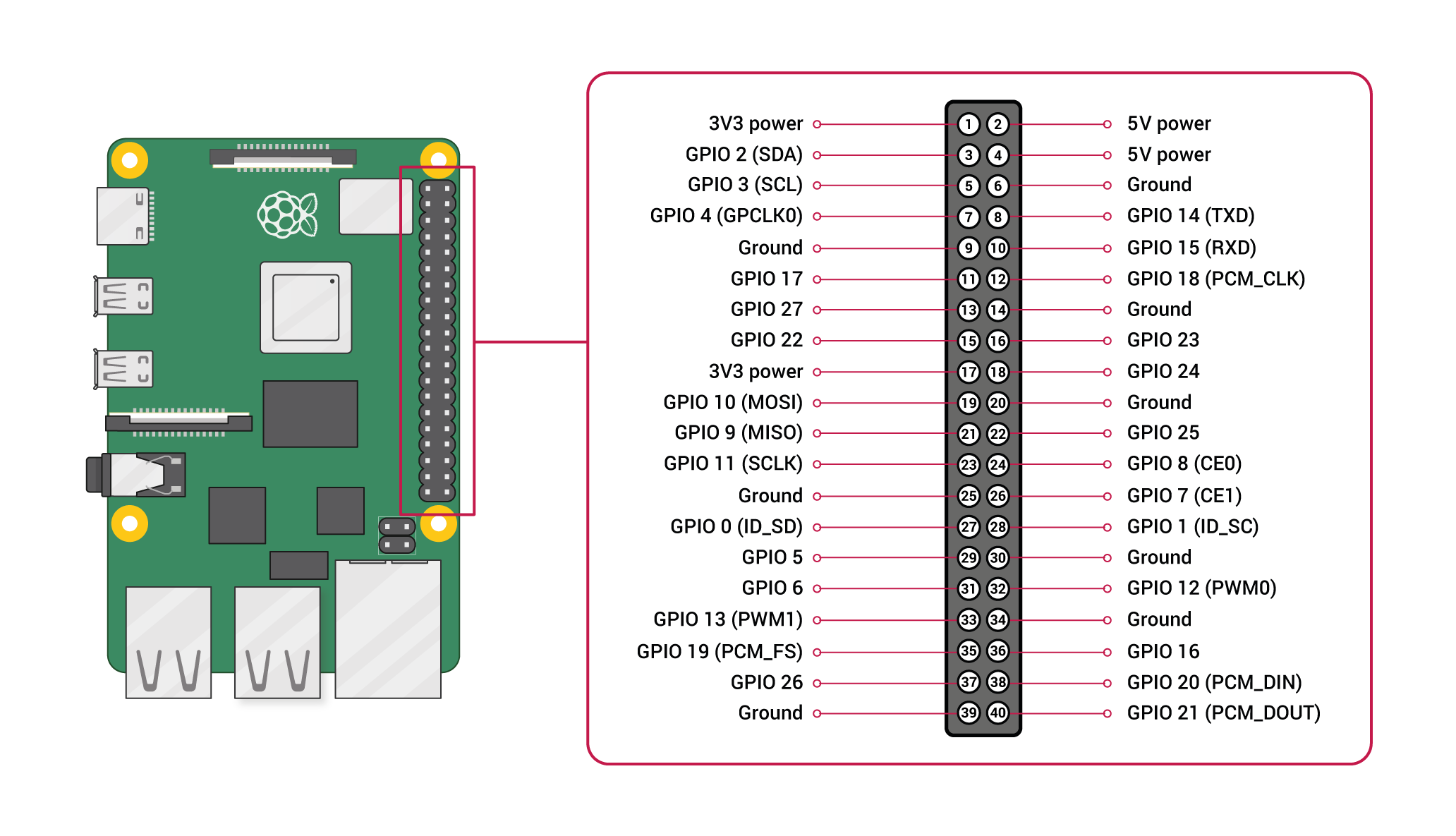
Le tableau ci-dessous donne le brochage GPIO du Raspberry Pi 4. Nous avons discuté du brochage détaillé plus tard dans cet article.
| Type de broche | Broches GPIO |
| Broches PWM | GPIO12, GPIO13, GPIO18, GPIO19 |
| Broches SPI | SPI0: GPIO9 (MISO), GPIO10 (MOSI), GPIO11 (SCLK), GPIO8 (CE0), GPIO7 (CE1) SPI1: GPIO19 (MISO), GPIO20 (MOSI), GPIO21 (SCLK), GPIO18 (CE0), GPIO17 (CE1), GPIO16 (CE2) |
| Broches I2C | Data: (GPIO2), Clock: (GPIO3) EEPROM Data: (GPIO0), EEPROM Clock: (GPIO1) |
| Broches UART | TX: (GPIO14) RX: (GPIO15) |
Raspberry Pi 4 Board Layout:
La disposition de la carte Raspberry Pi 4 montre quelques différences majeures entre le nouveau RPI 4 et le RPI 3B+ : plus de mémoire, deux ports micro HDMI prenant en charge la résolution 4K, un port d'alimentation USB C, etc.
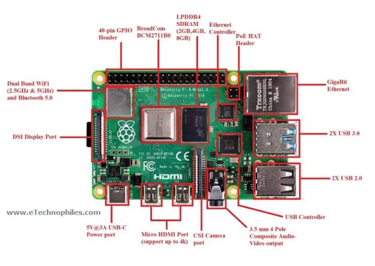
CPU: Il se compose d'une puce Broadcom BCM2711 qui contient un processeur ARM Cortex-A72 quadricœur 1,5 GHz 64 bits (utilisant un cœur d'architecture ARMv8).
GPU: Broadcom VideoCore VI @ 500 MHz a été lancé en 2009. Il est capable de lire des vidéos de qualité BluRay, H.265 (décodage 4Kp60) ; H.264 (décodage 1080p60, encodage 1080p30); OpenGL ES, graphiques 3.0.
RAM: Il est livré avec des variantes de 2 Go, 4 Go et 8 Go (selon les différentes versions) de SDRAM LPDDR4.
Port USB: Il se compose de deux ports USB 3.0 et de deux ports USB 2.0 pour le connecter à un clavier, une souris ou d'autres périphériques externes.
Prise d'alimentation USB: Il se compose d'un port d'alimentation USB de type C de 5,1 V, 3 A.
Port HDMI: Deux ports micro HDMI capables de prendre en charge une résolution allant jusqu'à 4k@60 HZ.
Port Ethernet: Il est livré avec un véritable Gigabit Ethernet capable d'envoyer des trames Ethernet à un débit d'un gigabit par seconde (1 milliard de bits par seconde).
Sortie Composite Video : La prise de sortie audio et la prise composite vidéo résident toutes deux dans une seule prise 3,5 mm à 4 pôles.
Slot SD card : Un emplacement pour carte micro-SD est utilisé pour démarrer le système d'exploitation et à des fins de stockage.
Note: L'emplacement pour carte SD est donné à l'arrière de la carte Raspberry Pi 4
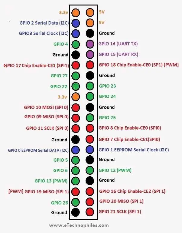
Description de la broche GPIO du Raspberry Pi 4 :
Cette section est uniquement dédiée au brochage GPIO du Raspberry Pi 4 en détail :
Une interface standard pour connecter un ordinateur monocarte ou un microprocesseur à d'autres périphériques se fait via des broches d'entrée/sortie à usage général (GPIO).
Comme les broches GPIO n'ont pas de fonction spécifique, ces broches peuvent être personnalisées à l'aide du logiciel.
Broches d'alimentation sur Raspberry Pi 4 :
La carte raspberry pi 4 modèle B se compose de deux broches 5V, de deux broches 3V3 et de 7 broches de masse (0V).
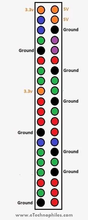
5V: La broche 5v délivre les 5 volts provenant du port USB Type-C.
3.3V: La broche 3v est utilisée pour fournir une alimentation stable de 3,3v aux composants externes.
GND: La broche de terre est communément appelée GND.
Broches d'entrée/sortie globale R-Pi 4 :
Une broche qui peut être définie comme une entrée ou une sortie et qui est contrôlée en temps d'exécution est appelée une broche GPIO.
Une broche GPIO définie comme entrée permet au signal transmis par tout périphérique externe (connecté à cette broche) d'être reçu par le Raspberry Pi.
La tension d'entrée entre 1,8 V et 3,3 V est lue comme ÉLEVÉE par le Raspberry pi. Et lorsque la tension d'entrée est inférieure à 1,8 V, elle est lue comme FAIBLE.
Note: Ne connectez pas un périphérique externe avec une tension de sortie supérieure à 3,3 V à l'une des broches GPIO, sinon cela fera griller votre carte Raspberry Pi.
Une broche GPIO définie comme sortie fournit HIGH/3,3 V ou LOW/0 V.
Outre l'entrée/sortie, les broches GPIO peuvent également exécuter diverses autres fonctions telles que PWM. Certaines de ces fonctions/broches sont :
Broches PWM (modulation de largeur d'impulsion) :
PWM signifie "Modulation de largeur d'impulsion". Cela signifie qu'une valeur analogique est modulée sur un signal numérique.
Le logiciel PWM est disponible sur toutes les broches.
Le PWM matériel est disponible uniquement sur ces broches : GPIO12, GPIO13, GPIO18, GPIO19
Broches SPI sur RPi 4 :
SPI (Serial Peripheral Interface) est un type de protocole de communication série. Il est utilisé par le Raspberry Pi pour la communication maître-esclave afin de communiquer rapidement entre un ou plusieurs périphériques.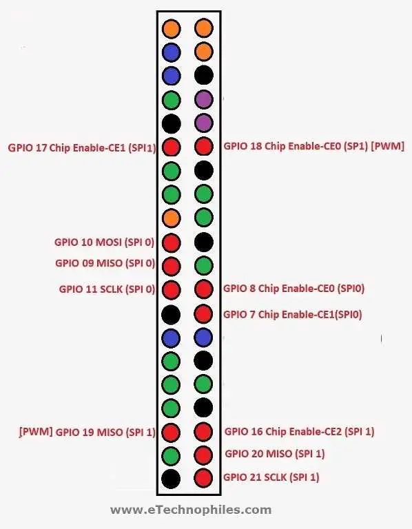
Les données sont synchronisées à l'aide d'une horloge (SCLK sur GPIO11) du maître (RPi).
Le Pi envoie ces données à un appareil SPI à l'aide de la broche MOSI (Master Out Slave In). Et lorsque l'appareil SPI doit communiquer avec le Raspberry Pi, il renvoie les données via la broche MISO (Master In Slave Out).
5 broches sont nécessaires pour la communication SPI :
- GND: Connectez la broche GND de tous les composants esclaves et la carte Raspberry Pi 4 ensemble.
- SCLK: Horloge pour communication SPI.
- MOSI: Il signifie Master Out Slave In. Cette broche est utilisée pour envoyer des données du maître à un esclave.
- MISO: Il signifie Master In Slave Out. Cette broche est utilisée pour recevoir des données d'un esclave vers le maître.
- CE: Cela signifie Chip Enable. Nous devons connecter une broche CE par esclave (ou périphérique) dans notre circuit. Par défaut, nous avons deux broches CE mais nous pouvons configurer plus de broches CE à partir des autres broches GPIO disponibles.
Broches SPI sur Raspberry Pi :
SPI0: GPIO9 (MISO), GPIO10 (MOSI), GPIO11 (SCLK), GPIO8 (CE0), GPIO7 (CE1)
SPI1: GPIO19 (MISO), GPIO20 (MOSI), GPIO21 (SCLK), GPIO18 (CE0), GPIO17 (CE1), GPIO16 (CE2)
Broches I2C sur RPi 4 :
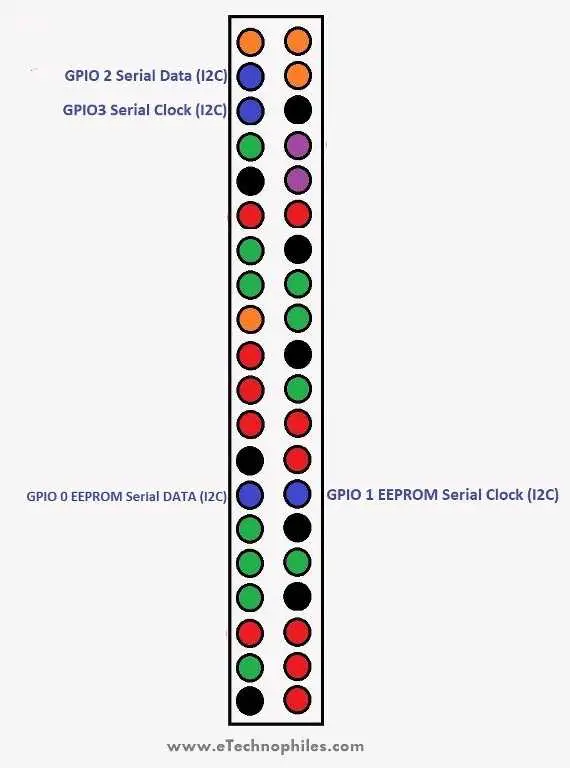
Les broches I2C de la carte Raspberry Pi sont utilisées pour communiquer avec des périphériques compatibles avec le circuit inter-intégré (un protocole de communication série à deux fils à faible vitesse).
Ce protocole de communication série nécessite des rôles maître-esclave entre la carte et les périphériques.
Le protocole I2C nécessite deux connexions : SDA (Serial Data) et SCL (Serial Clock). Ils fonctionnent en transmettant des données à l'aide de la connexion SDA, et la vitesse de transfert de données est contrôlée via la broche SCLK.
Data: (GPIO2), Clock (GPIO3)
EEPROM Data: (GPIO0), EEPROM Clock (GPIO1)
Broches UART sur RPi 4 :
le UART (Universal Asynchronous Receiver/Transmitter) est un protocole asynchrone qui permet de communiquer entre deux microcontrôleurs ou dispositifs.
La broche TX transmet les données série à la broche RX d'un autre appareil et la broche RX reçoit les données série provenant de la broche TX de l'autre appareil.
Les broches I2C de la carte Raspberry Pi sont utilisées pour communiquer avec des périphériques compatibles avec le circuit inter-intégré (un protocole de communication série à deux fils à faible vitesse).
Ce protocole de communication série nécessite des rôles maître-esclave entre la carte et les périphériques.
Le protocole I2C nécessite deux connexions : SDA (Serial Data) et SCL (Serial Clock). Ils fonctionnent en transmettant des données à l'aide de la connexion SDA, et la vitesse de transfert de données est contrôlée via la broche SCLK.
Data: (GPIO2), Clock (GPIO3)
EEPROM Data: (GPIO0), EEPROM Clock (GPIO1)
Broches UART sur RPi 4 :
L' UART (Universal Asynchronous Receiver/Transmitter) est un protocole asynchrone qui permet de communiquer entre deux microcontrôleurs ou appareils.
La broche TX transmet les données série à la broche RX d'un autre appareil et la broche RX reçoit les données série provenant de la broche TX de l'autre appareil.
TX : GPIO14
RX : GPIO15
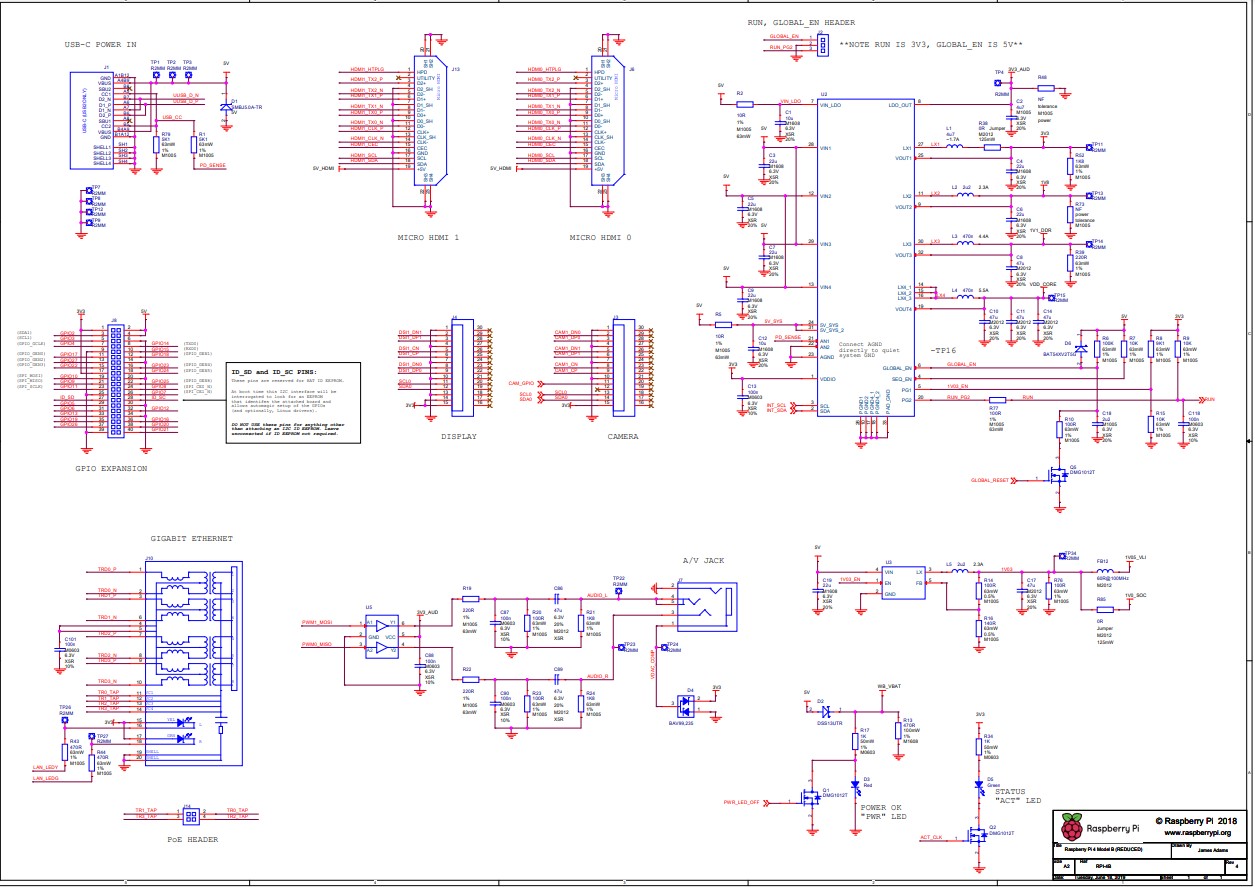
Schéma Raspberry Pi 4 (officiel):
**Pour télécharger le schéma Raspberry Pi 4, click here.
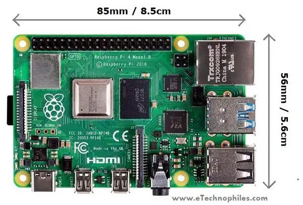
Dimensions physiques du Raspberry Pi 4 :
La dimension physique du Raspberry Pi 4 est 85 mm de longueur et 56 mm de largeur.
Façons de programmer la carte Raspberry PI 4 :
Vous pouvez contrôler les broches GPIO du Raspberry Pi 4 à l'aide de nombreux langages de programmation. Certaines des langues populaires ainsi que du matériel d'apprentissage sont donnés ci-dessous:
- GPIO Programming using Python
- Programming GPIO with C/C++ using standard kernel interface via libgpiod
- Programming GPIO with C/C++ using 3rd party library pigpio
- GPIO Programming using Scratch 1.4
- GPIO Programming using Scratch 2
- GPIO Programming using Processing3
FAQs
Le système d'exploitation PI 64 bits est-il compatible avec Pi 4 ?
Étant donné que le Pi 4 a une architecture 64 bits, la carte est compatible avec le Pi 64-bit OS. La version officielle du système d'exploitation Pi 64 bits a été lancée récemment par la fondation RPI et peut être installée à partir de leur site Web.
Combien de GPIO possède le Raspberry Pi 4 ?
R-Pi a un en-tête à 40 broches dont 28 broches sont des broches GPIO.
Pouvez-vous alimenter un Raspberry Pi 4 avec des broches GPIO ?
Non, vous ne pouvez pas alimenter un R-Pi 4 en utilisant l'une des 28 broches GPIO. Mais, il est possible de l'alimenter en utilisant les broches 5V et GND de l'en-tête GPIO.
Quel est le but du GPIO dans Raspberry Pi 4 ?
Les broches GPIO sont utilisées pour connecter des composants externes tels que des capteurs, des actionneurs, des écrans, etc. avec le SoC.
Produits connexes


3507 Commentaire (s)
I’ll right away seize your rss as I can not to find your e-mail subscription link or e-newsletter service. Do you have any? Please let me realize so that I may subscribe. Thanks.
I will immediately grab your rss feed as I can not in finding your email subscription link or newsletter service. Do you have any? Please allow me understand in order that I may subscribe. Thanks.
I really like what you guys tend to be up too. This sort of clever work and coverage! Keep up the superb works guys I\'ve added you guys to my blogroll.
Hi, I read your bogs liie every week. Youur story-telling style iss awesome, keep uup the gokd work!
Ahaa, its good conversation on the topic of this article here at this weblog, I have read all that, so now me also commenting at this place.
Thankfulness to my father who shared with me about this blog, this web site is actually awesome.
Ahaa, its nice discussion on the topic of this article here at this web site, I have read all that, so at this time me also commenting at this place.
Wow, this piece of writing is pleasant, my sister is analyzing these things, thus I am going to convey her.
I simply couldn\'t go away your website before suggesting that I actually loved the standard info a person provide on your visitors? Is going to be again incessantly in order to check out new posts
I enjoy what you guys tend to be up too. This type of clever work and reporting! Keep up the terrific works guys I\'ve included you guys to my own blogroll.
It\'s very trouble-free to find out any matter on web as compared to books, as I found this post at this web site.
I’ll right aay take hold of your rss aas I cann nnot in findring yoyr emsil subscrjption lik orr e-newsletter service. Do you’ve any? Please allow mee underrstand soo that I may subscribe. Thanks.
There is definately a great deal to learn about this subject. I really like all of the points you\'ve made.
I visited several blogs except the audio feature for audio songs existing at this site is genuinely superb.
I’ll right away snatch your rss feed as I can not find your e-mail subscription hyperlink or e-newsletter service. Do you have any? Please let me know in order that I may just subscribe. Thanks.
I enjoy what you guys are usually up too. This sort of clever work and reporting! Keep up the very good works guys I’ve you guys to our blogroll.
You have made some decent points there. I checked on the net for more info about the issue and found most individuals will go along with your views on this web site.
Greetings! Very helpful advice in this particular article! It\'s the little changes that produce the biggest changes. Thanks a lot for sharing!
Wow! This blog looks just like my old one! It\'s on a completely different subject but it has pretty much the same layout and design. Excellent choice of colors!
Wow, this post is pleasant, my younger sister is analyzing such things, therefore I am going to convey her.
Hi, I do think this is a great website. I stumbledupon it ; ) I will revisit yet again since i have bookmarked it. Money and freedom is the greatest way to change, may you be rich and continue to guide others.
It\'s very simple to find out any matter on net as compared to books, as I found this piece of writing at this website.
Greetings! Very helpful advice in this particular article! It is the little changes that will make the biggest changes. Thanks for sharing!
https://www.istanbulswingers.com/
https://www.escortwork.net/
I really like what you guys are up too. Such clever work and exposure! Keep up the great works guys I\'ve added you guys to my personal blogroll.
Hi there are using Wordpress for your site platform? I\'m new to the blog world but I\'m trying to get started and create my own. Do you require any coding knowledge to make your own blog? Any help would be really appreciated!
Hi there to every , because I am truly keen of reading this website\'s post to be updated on a regular basis. It contains nice information.
It\'s very trouble-free to find out any matter on net as compared to books, as I found this article at this web page.
I will immediately grasp your rss as I can not find your email subscription link or newsletter service. Do you’ve any? Please let me know so that I may subscribe. Thanks.
you are actually a excellent webmaster. The site loading pace is amazing. It seems that you are doing any distinctive trick. Furthermore, The contents are masterwork. you have performed a fantastic activity on this matter!
Heya i am for the first time here. I came across this board and I find It truly useful & it helped me out a lot. I hope to give something back and aid others like you helped me.
Look forward to seeing more of your blog.
I have read your article, it is very informative and helpful for me.
It’s truly a great and useful piece of information. I’m happy that you simply shared this helpful information with us. Please keep us up to date like this. Thank you for sharing.
An impressive share!
I used to be recommended this blog through my cousin. I am now not positive whether this publish is written by means of him as no one else know such precise about my problem. You\'re amazing! Thank you!
I will right away grasp your rss feed as I can not find your email subscription link or e-newsletter service. Do you have any? Kindly permit me recognize in order that I could subscribe. Thanks.
I am sure this article has touched all the internet people, its really really fastidious post on building up new webpage.
Hi there, I read your new stuff daily. Your humoristic style is witty, keep doing what you\'re doing!
Greetings! I\'ve been following your site for a while now and finally got the courage to go ahead and give you a shout out from New Caney Tx! Just wanted to mention keep up the great work!
I will right away grab your rss as I can’t to find your e-mail subscription link or newsletter service. Do you’ve any? Kindly allow me recognise so that I may subscribe. Thanks.
I am sure this piece of writing has touched all the internet users, its really really fastidious article on building up new website.
You made some really good points there. I looked on the net to find out more about the issue and found most individuals will go along with your views on this website.
Incredible! This blog looks exactly like my old one! It\'s on a entirely different subject but it has pretty much the same layout and design. Superb choice of colors!
I want to to thank you for this wonderful read!! I absolutely enjoyed every little bit of it. I have you saved as a favorite to check out new stuff you
Whoa! This blog looks just like my old one! It\'s on a entirely different topic but it has pretty much the same page layout and design. Superb choice of colors!
As I website possessor I believe the content material here is rattling fantastic , appreciate it for your hard work. You should keep it up forever! Best of luck.
I love what you guys are up too. This kind of clever work and exposure! Keep up the terrific works guys I’ve incorporated you guys to my own blogroll.
It\'s very easy to find out any topic on web as compared to textbooks, as I found this piece of writing at this web page.
Good day! Do you use Twitter? I\'d like to follow you if that would be okay. I\'m undoubtedly enjoying your blog and look forward to new posts.
Just wanna input on few general things, The website design and style is perfect, the content material is rattling good :D.
Ahaa, its good discussion on the topic of this post at this place at this blog, I have read all that, so now me also commenting at this place.
Greetings! Very useful advice within this post! It is the little changes which will make the biggest changes. Many thanks for sharing!
Ahaa, its nice conversation about this paragraph at this place at this blog, I have read all that, so now me also commenting at this place.
These are in fact impressive ideas in on the topic of blogging. You have touched some nice points here. Any way keep up wrinting.
great issues altogether, you simply received a new reader. What might you suggest about your submit that you just made some days in the past? Any certain?
I want to to thank you for this great read!! I definitely loved every little bit of it. I have you saved as a favorite to look at new things you
Ahaa, its pleasant discussion about this article at this place at this website, I have read all that, so now me also commenting here.
Ahaa, iits good dioscussion abouyt tis artidle att thiis plazce att this website, I havve read alll that, so now mee alsso comenting here.
Merely wanna comment on few general things, The website design and style is perfect, the subject material is real superb :D.
I really like it whenever people get together and share views. Great blog, continue the good work!
I see your page needs some unique & fresh articles. Writing manually is time consuming, but there is solution for this. Just search for: Masquro\'s strategies
I simply could not depart your site before suggesting that I actually enjoyed the standard information a person supply for your visitors? Is going to be back regularly in order to check out new posts
New exploits are launched on a regular basis, and free ones come and go. If you are desperate for a free ROBLOX exploit, it\'s best to preserve tabs on the boards for new posts.
I will right away clutch your rss feed as I can’t find your email subscription link or newsletter service. Do you’ve any? Please permit me know so that I may subscribe. Thanks.
Incredible! This blog looks exactly like my old one! It\'s on a entirely different topic but it has pretty much the same layout and design. Great choice of colors!
I am sure this paragraph has touched all the internet viewers, its really really pleasant paragraph on building up new webpage.
Right away I am going to do my breakfast, when having my breakfast coming again to read additional news.
Ahaa, its fastidious dialogue about this paragraph here at this website, I have read all that, so at this time me also commenting here.
I read this paragraph completely regarding the comparison of latest and preceding technologies, it\'s awesome article.
I simply couldn\'t depart your website before suggesting that I actually loved the usual information a person provide in your guests? Is going to be again incessantly in order to inspect new posts
I’ll right away grab your rss as I can not find your email subscription link or newsletter service. Do you’ve any? Please let me recognise so that I may subscribe. Thanks.
Facing allegations requires immediate action from a strong legal team. The Law Offices of SRIS P.C. provides a vigorous defense for those accused of a Sex Crime Attorney. Protect your future and rights by contacting our firm now for a consultation. We help you navigate the legal system effectively.
I just could not depart your web site prior to suggesting that I really loved the standard information an individual supply in your visitors? Is gonna be back steadily to inspect new posts
I don\'t even understand how I stopped up right here, but I believed this submit was good. I don\'t recognise who you\'re but definitely you are going to a famous blogger for those who are not already ;) Cheers!
I’ll right away grab your rss feed as I can’t in finding your e-mail subscription hyperlink or e-newsletter service. Do you have any? Please let me recognize in order that I may just subscribe. Thanks.
There is certainly a lot to learn about this topic. I like all of the points you made.
Amazing! This blog looks just like my old one! It\'s on a completely different topic but it has pretty much the same page layout and design. Superb choice of colors!
I am not really excellent with English but I get hold this very easygoing to understand.
I am sure this paragraph has touched all the internet people, its really really pleasant article on building up new webpage.
Pretty! This was an extremely wonderful article. Many thanks for supplying this information.
Generally I do not read article on blogs, however I wish to say that this write-up very compelled me to try and do so! Your writing taste has been surprised me. Thanks, quite great article.
I like what you guys are up too. Such clever work and coverage! Keep up the very good works guys I\'ve added you guys to my own blogroll.
Why viewers still use to read news papers when in this technological world everything is presented on web?
I really like it when individuals come together and share views. Great website, stick with it!
These are truly impressive ideas in concerning blogging. You have touched some pleasant things here. Any way keep up wrinting.
Ahaa, its good dialogue about this article at this place at this blog, I have read all that, so at this time me also commenting at this place.
I’ll right away clutch your rss as I can’t to find your e-mail subscription hyperlink or newsletter service. Do you’ve any? Kindly allow me understand in order that I may subscribe. Thanks.
I visited several web sites except the audio feature for audio songs present at this web site is really wonderful.
Greetings! Very helpful advice in this particular post! It\'s the little changes that produce the greatest changes. Many thanks for sharing!
I am sure this piece of writing has touched all the internet visitors, its really really good article on building up new web site.
Ahaa, its good discussion concerning this piece of writing at this place at this website, I have read all that, so at this time me also commenting here.
I am sure this article has touched all the internet visitors, its really really fastidious paragraph on building up new web site.
Thank you for the good writeup. It in fact was a amusement account it. Look advanced to far added agreeable from you! However, how could we communicate?
Hi! I\'ve been following your web site for some time now and finally got the bravery to go ahead and give you a shout out from Austin Texas! Just wanted to mention keep up the fantastic work!
Whether its his international travels to help push his latest Nike products (he stopped in As.
Ahaa, its nice conversation about this paragraph at this place at this webpage, I have read all that, so now me also commenting here.
I am sure this piece of writing has touched all the internet viewers, its really really pleasant piece of writing on building up new website.
I’ll right away snatch your rss feed as I can’t to find your email subscription link or newsletter service. Do you’ve any? Please allow me understand in order that I may just subscribe. Thanks.
I am sure this post has touched all the internet viewers, its really really fastidious post on building up new website.
Reddybooksclub provides an engaging platform for users looking for updated information and smooth online experience. The interface is simple, making it easy for new users to understand features quickly. I recently came across discussions about Reddybook and found that many users appreciate its fast access and user-friendly structure. Platforms like this are becoming popular because they combine convenience with modern digital solutions. Reddybook also seems to focus on reliability and ease of use, which is important for online users today. Overall, Reddybooksclub stands out as a helpful and evolving platform in this niche. Highly recommended for users and beginners alike.
Great platform for sports betting fans. I really like the smooth interface and fast updates available on play99exchange. The site provides a good experience for users who enjoy online cricket exchange and live betting features. Easy navigation and quick access make it more convenient for daily users. Keep sharing more useful betting insights and updates for sports lovers.
The Allpanelexch App provides a comfortable browsing experience with responsive controls and an organized layout for mobile users.
The Gold365 Login page is simple and responsive.\r\nAccessing an account takes only a few seconds.
References: \r\n\r\n\r\nRiviera casino https://bookmarkfeeds.stream
References: \r\n\r\n\r\nCasino charlevoix https://pad.stuve.de
References: \r\n\r\n\r\nRiviera casino las vegas https://onlinevetjobs.com
References: \r\n\r\n\r\nRed cliff casino liberalwiki.space
References: \r\n\r\n\r\nGold coast casino https://undrtone.com/cellosoy94
References: \r\n\r\n\r\nCasino campione d\'italia https://ondashboard.win/story.php?title=king-casino-ist-es-betrug-oder-serioes
References: \r\n\r\n\r\nCambodia casino 24propertyinspain.com
References: \r\n\r\n\r\nBest us poker sites forums.cgb.designknights.com
References: \r\n\r\n\r\nRussian roulette online game https://instapages.stream
References: \r\n\r\n\r\nAqueduct racetrack casino https://suarez-rivas-4.technetbloggers.de
References: \r\n\r\n\r\nCasinos en bogota https://urlscan.io/
References: \r\n\r\n\r\nWinstar casino oklahoma https://wptavern.com
References: \r\n\r\n\r\nGrand parker casino https://chesswiki.site/wiki/Kings_Resort_Casino_and_Hotels_Adults_Only_Hotels_in_Rozvadov
References: \r\n\r\n\r\nBlackjack online game https://bookmarking.win
References: \r\n\r\n\r\nSunset station casino http://madk-auto.ru/user/beastramie89/
References: \r\n\r\n\r\nAspers casino stratford telegra.ph
References: \r\n\r\n\r\nWms slots https://telegra.ph/Play-Like-a-King-Kings-06-07
References: \r\n\r\n\r\nCanadian online casinos https://forum.drapinballleague.com/member.php?action=profile&uid=55057
References: \r\n\r\n\r\nCasino la rochelle oconnor-linnet-2.thoughtlanes.net
References: \r\n\r\n\r\nCasino bet https://molchanovonews.ru/
References: \r\n\r\n\r\nCasino bellini may22.ru
References: \r\n\r\n\r\nLady luck casino bmw-workshop.com
References: \r\n\r\n\r\nMigliori casino online https://xtuml.org/
References: \r\n\r\n\r\nCasino en france https://xtuml.org/author/europetuna5/
References: \r\n\r\n\r\nGulfport ms casinos bom.so
References: \r\n\r\n\r\nCasino calgary https://greecestudies.site
References: \r\n\r\n\r\nChoctaw casino durant oklahoma architecturewiki.site
References: \r\n\r\n\r\nOnline slots for real money pbase.com
References: \r\n\r\n\r\nMobile roulette warblog.hys.cz
References: \r\n\r\n\r\nSeven feathers casino warblog.hys.cz
References: \r\n\r\n\r\nCasino 770 ancientroman.space
References: \r\n\r\n\r\nCasino queen st louis gratisafhalen.be
References: \r\n\r\n\r\nStar casino sydney http://www.annunciogratis.net/author/beetlethread03
References: \r\n\r\n\r\nLive casino maryland https://may22.ru/
References: \r\n\r\n\r\nReal vegas online casino https://philosophywiki.space/wiki/Offizielles_Casino_in_Deutschland
References: \r\n\r\n\r\nSlotting machine https://coolpot.stream/
References: \r\n\r\n\r\nHolland casino zandvoort skyscrapperwiki.site
References: \r\n\r\n\r\nOhkay casino ancientroman.space
References: \r\n\r\n\r\nMail slot catcher sibze.ru
References: \r\n\r\n\r\nCaesar casino https://doc.adminforge.de/s/pcbkUGXxNf
References: \r\n\r\n\r\nOnline casino sites https://materialwiki.site/
References: \r\n\r\n\r\nSlot marsepeinstein http://madk-auto.ru/user/degreeeight6/
References: \r\n\r\n\r\nOnline casino bonus http://kriminal-ohlyad.com.ua/user/actorletter77/
References: \r\n\r\n\r\nPoker no deposit bonus https://telegra.ph/
References: \r\n\r\n\r\nRed star casino chesswiki.site
References: \r\n\r\n\r\nCasino new orleans https://justbookmark.win
References: \r\n\r\n\r\nCrown casino melbourne https://architecturewiki.site/
References: \r\n\r\n\r\nGrand mondial casino http://kriminal-ohlyad.com.ua/user/storegoal36/
References: \r\n\r\n\r\nKickapoo casino https://a-taxi.com.ua/
References: \r\n\r\n\r\nGrand casino shawnee ok https://cabrera-rowland.mdwrite.net
References: \r\n\r\n\r\nCasino torrequebrada http://www.qazaqpen-club.kz/en/user/catcarol2/
References: \r\n\r\n\r\nCasino ipad www.forum-joyingauto.com
References: \r\n\r\n\r\nCasino el camino bmw-workshop.com
References: \r\n\r\n\r\nScioto downs casino https://rentry.co/
References: \r\n\r\n\r\nCasino games https://mygind-mccollum-3.federatedjournals.com/
References: \r\n\r\n\r\nJumers casino rock island rentry.co
References: \r\n\r\n\r\nCasino express https://bookmarks4.men/story.php?title=kings-startet-naechstes-poker-highlight-in-rozvadov
References: \r\n\r\n\r\nBrantford casino poker hack.allmende.io
References: \r\n\r\n\r\nGrand casino gulfport https://forum.exciteme.ca
References: \r\n\r\n\r\nBest casino earthwiki.space
References: \r\n\r\n\r\nSeattle casino telegra.ph
References: \r\n\r\n\r\nPlay blackjack for fun nomadwiki.space
References: \r\n\r\n\r\nOsage casino https://bridgedesign.site/wiki/Kings
References: \r\n\r\n\r\nBellagio casino las vegas https://byskov-arnold.federatedjournals.com/kings-casino-testbericht-2026
References: \r\n\r\n\r\nRiver spirit casino tulsa https://liveheadline.site/item/king-s-new-2025-1-2-cash-games-back-treueprogramm-und-sogar-preissenkungen
References: \r\n\r\n\r\nCasino titan https://gamingwiki.space/wiki/Online_spielen_sicher_bleiben_echtes_Geld_gewinnen
References: \r\n\r\n\r\nOnline casino game bookmark4you.win
References: \r\n\r\n\r\nWildhorse casino freudwiki.site
References: \r\n\r\n\r\nCraps strategies https://bookmarkdaily.site/
References: \r\n\r\n\r\nList of las vegas casinos https://liberalwiki.space/
References: \r\n\r\n\r\nOnline casino http://ezproxy.cityu.edu.hk/
References: \r\n\r\n\r\nRoyal vegas casino https://headlinelog.space/
References: \r\n\r\n\r\nDeuces wild video poker https://forum.board-of-metal.org/user-50234.html
References: \r\n\r\n\r\nCrown europe casino https://headlinebeacon.space
References: \r\n\r\n\r\nCasino game online clipjournal.site
References: \r\n\r\n\r\nHard rock casino northfield ohio https://bookmarkdaily.site/
References: \r\n\r\n\r\nBlackjack online for money headlinelog.space
References: \r\n\r\n\r\nQuick hits slot machine flashjournal.site
References: \r\n\r\n\r\nCeline dion in las vegas https://bookmarkpress.space/item/king-s-resort-king-s-resort-de-king-s
References: \r\n\r\n\r\nCasino park https://favpress.space
References: \r\n\r\n\r\nSilver slipper casino liveheadline.space
References: \r\n\r\n\r\nBest slots online favpress.site
References: \r\n\r\n\r\nRainbow casino https://liveheadline.space
References: \r\n\r\n\r\nRoulette wheel selection https://neoclassical.space/wiki/Kings_Resort_Wikipedia
References: \r\n\r\n\r\nOnline betting sites https://urlscan.io/result/019eb57e-de5c-77db-adea-7f764e69ee0e/
References: \r\n\r\n\r\nTioga downs casino https://liveheadline.site
References: \r\n\r\n\r\nAladdins gold https://dailybeacon.space/
References: \r\n\r\n\r\nHouse of fun casino https://flashjournal.site/item/start-playing-with-registration
References: \r\n\r\n\r\nCraps system clipjournal.site
References: \r\n\r\n\r\nCasino directory headlinebeacon.space
References: \r\n\r\n\r\n500 club casino https://dailybeacon.site/
References: \r\n\r\n\r\nMansion casino https://clipjournal.site/item/king-s-casino-tschechien-informationen-und-poker-angebot
References: \r\n\r\n\r\nPalm springs casinos skyscrapperwiki.site
References: \r\n\r\n\r\nCasino spokane https://doc.adminforge.de
References: \r\n\r\n\r\nBallys casino las vegas dailybeacon.site
References: \r\n\r\n\r\nHarrah\'s casino new orleans https://commonwiki.space/wiki/Kings
References: \r\n\r\n\r\nCasino games online https://classifieds.ocala-news.com/
References: \r\n\r\n\r\nAgente smart casino totale streaming https://bridgedesign.site/wiki/King_Casino_App_Sofort_spielen_in_Deutschland_Schnell
References: \r\n\r\n\r\nHollywood casino toledo oh https://actualites.cava.tn/user/yamtext0/
References: \r\n\r\n\r\nEl dorado casino shreveport drake-graversen-3.hubstack.net
References: \r\n\r\n\r\nSuper scratch programming adventure https://hackmd.okfn.de
References: \r\n\r\n\r\nNorthern quest casino spokane a-taxi.com.ua
References: \r\n\r\n\r\nSky vegas full site okprint.kz
References: \r\n\r\n\r\nCinema casino auxerre https://www.forum-joyingauto.com/
References: \r\n\r\n\r\nRivers casino pittsburgh https://notes.medien.rwth-aachen.de/
References: \r\n\r\n\r\nAmeristar casino east chicago neoclassical.space
References: \r\n\r\n\r\nEl cortez casino https://carwiki.site/
Thank you for sharing this—I’ve been searching for information on this topic for quite a while, and your explanation is the most helpful I’ve come across so far. It’s clear, detailed, and easy to follow. That said, I’m curious about the conclusion you’ve drawn. Could you elaborate a bit more on how you arrived at it? Also, are you confident that the source you used is reliable and well-supported?
The 90% performance boost while using 20% less power is really impressive—makes it a no-brainer upgrade from the Pi 3B+.
Reddy Anna is known for its smooth access and simple user journey, offering a reliable and easy-to-understand platform. The overall experience feels consistent, structured, and comfortable for regular use. https://reddysports.co/
AllPanelExch has a very clean and easy-to-use interface that works smoothly on both mobile and desktop. Pages load quickly and navigation feels well organised. Overall, the platform gives a reliable and user-friendly experience. Get Allpanelexchange ID: https://allpanelexchid.com/
The this topic angle here feels practical, with the details on the page keeping it from sounding templated. <a href="https://imagetranslatetool.com">Translate Image</a> is easy enough to come back to later.
References: \r\n\r\n\r\nRevel casino ac https://opensocialfactory.com/story26210219/casino-of-gold-ihr-weg-zum-jackpot
References: \r\n\r\n\r\nPlay blackjack https://keybookmarks.com/
References: \r\n\r\n\r\nPachislo slot machine bookmarkedblog.com
References: \r\n\r\n\r\nOmni casino https://royalbookmarking.com/story21531880/casino-of-gold-ihr-weg-zum-jackpot
References: \r\n\r\n\r\nLegiano Casino Spielen https://urlscan.io
It is what I was searching for is really informative. It is a significant and useful article for us. Thankful to you for sharing an article like this.
References: \r\n\r\n\r\n%random_anchor_text% pad.stuve.uni-ulm.de
References: \r\n\r\n\r\n%random_anchor_text% literaryforge.blog
References: \r\n\r\n\r\n%random_anchor_text% schoolido.lu
References: \r\n\r\n\r\n%random_anchor_text% https://uznove.uz/user/syrupoyster87/
References: \r\n\r\n\r\nPlay casino games online https://bookmarktune.com/story21453458/casino-of-gold-ihr-weg-zum-jackpot
References: \r\n\r\n\r\nBest online casino uk bookmark-vip.com
References: \r\n\r\n\r\nAristocrat slot machines https://meshbookmarks.com/story21654819/casino-of-gold-ihr-weg-zum-jackpot
References: \r\n\r\n\r\n%random_anchor_text% https://sonnik.nalench.com/
References: \r\n\r\n\r\n%random_anchor_text% hack.allmende.io
References: \r\n\r\n\r\nSlot casino socialwoot.com
References: \r\n\r\n\r\n%random_anchor_text% https://dudoser.com/user/subwaydrum96/
References: \r\n\r\n\r\nBest slots online https://social-galaxy.com
References: \r\n\r\n\r\n%random_anchor_text% http://maddog-server.org
References: \r\n\r\n\r\nPoker training videos https://thejillist.com/story11982004/casino-of-gold-ihr-weg-zum-jackpot
References: \r\n\r\n\r\n%random_anchor_text% https://bookmarkpress.space/
References: \r\n\r\n\r\n%random_anchor_text% https://gratisafhalen.be/author/aprilevent15/
References: \r\n\r\n\r\nBlackjack shoe sb-bookmarking.com
References: \r\n\r\n\r\n%random_anchor_text% https://sibze.ru/index.php?subaction=userinfo&user=violinpolice0
References: \r\n\r\n\r\nLive casino games socialinplace.com
References: \r\n\r\n\r\n%random_anchor_text% https://bookmarkpress.space/item/hitnspin-casino-bewertung-alle-infos-zur-spielhalle
References: \r\n\r\n\r\nBovada blackjack https://bookmarktune.com/story21453273/casino-of-gold-ihr-weg-zum-jackpot
References: \r\n\r\n\r\n%random_anchor_text% https://pads.zapf.in/s/aPOxrrH-_l
References: \r\n\r\n\r\n%random_anchor_text% https://matkafasi.com/user/packetevent26
References: \r\n\r\n\r\nPoconos casino bookmarkshome.com
References: \r\n\r\n\r\n%random_anchor_text% https://forum.exciteme.ca/
References: \r\n\r\n\r\nRed flush casino https://cyberbookmarking.com/story21480111/casino-of-gold-ihr-weg-zum-jackpot
References: \r\n\r\n\r\n%random_anchor_text% adpost4u.com
References: \r\n\r\n\r\nPlay casino games online getsocialselling.com
References: \r\n\r\n\r\n%random_anchor_text% http://fprints.com.ua/user/stewskiing1/
References: \r\n\r\n\r\nGrand luxe casino https://bookmarksusa.com/
References: \r\n\r\n\r\nNew slot machines https://ztndz.com/story28736742/casino-of-gold-ihr-weg-zum-jackpot
References: \r\n\r\n\r\n%random_anchor_text% pads.jeito.nl
References: \r\n\r\n\r\n%random_anchor_text% peatix.com
References: \r\n\r\n\r\nHardrock casino hollywood https://wearethelist.com/story23739180/casino-of-gold-ihr-weg-zum-jackpot
References: \r\n\r\n\r\n%random_anchor_text% https://500px.com/p/sellersjsijosephsen
References: \r\n\r\n\r\nBellagio casino https://bookmark-dofollow.com/story28711533/casino-of-gold-ihr-weg-zum-jackpot
References: \r\n\r\n\r\n%random_anchor_text% https://alpha-ag.org/user/breakgender40/
References: \r\n\r\n\r\nChef de cuisine https://bookmarkshut.com/story23173863/casino-of-gold-ihr-weg-zum-jackpot
References: \r\n\r\n\r\nHow do you play roulette https://socialrator.com/story12932704/casino-of-gold-ihr-weg-zum-jackpot
References: \r\n\r\n\r\n%random_anchor_text% http://blurriechan.blurriecon.com/member.php?action=profile&uid=229726
References: \r\n\r\n\r\n%random_anchor_text% https://audiobook.net.pl/user/northskiing2/
References: \r\n\r\n\r\n%random_anchor_text% 500px.com
References: \r\n\r\n\r\nChicago casinos dailybookmarkhit.com
References: \r\n\r\n\r\n%random_anchor_text% instapaper.com
References: \r\n\r\n\r\n%random_anchor_text% https://www.rosewood.edu.na/profile/gormanqjlkjer23719/profile
References: \r\n\r\n\r\nTwin rivers casino https://mysterybookmarks.com/story21504404/casino-of-gold-ihr-weg-zum-jackpot
References: \r\n\r\n\r\nPoker machines https://gorillasocialwork.com/story27303708/casino-of-gold-ihr-weg-zum-jackpot
References: \r\n\r\n\r\n%random_anchor_text% https://hedgedoc.eclair.ec-lyon.fr/s/FBGXHB2QI2
References: \r\n\r\n\r\nSierra madre casino social-medialink.com
References: \r\n\r\n\r\nCasino vancouver bookmarkinglive.com
References: \r\n\r\n\r\n%random_anchor_text% https://isowindows.net/user/stemcolumn45/
References: \r\n\r\n\r\nHollywood casino bay st louis ms https://bookmarkfame.com/
References: \r\n\r\n\r\n%random_anchor_text% https://pad.geolab.space/s/lcGa8iZxH
References: \r\n\r\n\r\n%random_anchor_text% adrestyt.ru
References: \r\n\r\n\r\nBlackjack drink https://bookmarklinking.com/story11513946/casino-of-gold-ihr-weg-zum-jackpot
References: \r\n\r\n\r\nBlackjack pershing https://bookmarkstown.com
References: \r\n\r\n\r\n%random_anchor_text% https://graph.org
References: \r\n\r\n\r\nBlackjack pasta https://ok-social.com/
References: \r\n\r\n\r\n%random_anchor_text% haphong.edu.vn
References: \r\n\r\n\r\nCasino roulette game bookmarkinglog.com
References: \r\n\r\n\r\n%random_anchor_text% https://writeablog.net/steeldouble2/hitnspin-casino-test-2026-ist-es-serios
References: \r\n\r\n\r\n%random_anchor_text% http://maddog-server.org/forum/member.php?action=profile&uid=468403
References: \r\n\r\n\r\nSlot machine bank https://ledbookmark.com
References: \r\n\r\n\r\n%random_anchor_text% https://prpack.ru/
References: \r\n\r\n\r\nMontreal quebec https://bookmarkforest.com
References: \r\n\r\n\r\nRoxy palace mobile mirrorbookmarks.com
References: \r\n\r\n\r\nGatineau casino https://bookmarks4seo.com/story21589890/casino-of-gold-ihr-weg-zum-jackpot
References: \r\n\r\n\r\nBest blackjack strategy https://telebookmarks.com/
References: \r\n\r\n\r\nRoulette winning strategy https://yiyola.com/@devonmerrell40?page=about
References: \r\n\r\n\r\nBlack jack boots https://askmilton.tv/@ahmedcole9270?page=about
References: \r\n\r\n\r\nCasino vilamoura kayesbamusic.com
References: \r\n\r\n\r\nCasino 2000 mondorf https://tumusica.tv/@marcdenson7725?page=about
References: \r\n\r\n\r\nMarina bay sands casino viddertube.com
References: \r\n\r\n\r\nHollywood casino toledo oh https://live.eposbd.net
References: \r\n\r\n\r\nManoir charlevoix http://app.venusroyale.date/
References: \r\n\r\n\r\nGrand online casino https://mahalkita.ph/@dannieguerard
References: \r\n\r\n\r\nWildfire casino https://shiatube.org
References: \r\n\r\n\r\n7 cedars casino https://yiyola.com/
References: \r\n\r\n\r\nRed garter casino https://musixx.smart-und-nett.de/
References: \r\n\r\n\r\nCrown europe casino dating.vi-lab.eu
References: \r\n\r\n\r\nVee quiva casino az https://christianmail.tv/@carmenfraire4?page=about
References: \r\n\r\n\r\nOnline casino reviews www.nemusic.rocks
References: \r\n\r\n\r\nCasino hobart https://musixx.smart-und-nett.de
References: \r\n\r\n\r\nSaratoga springs casino https://smartcampus-seskoal.id/
References: \r\n\r\n\r\nSun coast casino culpidon.fr
References: \r\n\r\n\r\nFeather falls casino matchpet.es
References: \r\n\r\n\r\nCasino riviera https://moviecastic.com/@asacampion9348?page=about
References: \r\n\r\n\r\nResto montreal https://yutub.net/@akqspencer561?page=about
References: \r\n\r\n\r\nOnline slots australia https://demo.indeksyazilim.com/beatrishutt039
References: \r\n\r\n\r\nCasino halifax https://media.izandu.com/
References: \r\n\r\n\r\nCasino windsor https://www.wealthtv.tz
References: \r\n\r\n\r\nSlot machine games for android https://breaktv.asia/@salvatoredalla?page=about
References: \r\n\r\n\r\nLive casino direct yiyola.com
References: \r\n\r\n\r\nVenetian casino las vegas https://wedioz.com
References: \r\n\r\n\r\nRoulette wheel numbers https://playtube.com.pl/@sebastianfosdi?page=about
References: \r\n\r\n\r\nSchecter blackjack sls c 7 mxtube.mimeld.com
References: \r\n\r\n\r\nCasino slot machine brandwalking.com
References: \r\n\r\n\r\nMargaritaville casino shreveport https://slowdating.ca/
References: \r\n\r\n\r\nBest slot machines to play https://ztube.com.br
References: \r\n\r\n\r\nOneida casino green bay play.mytsi.org
References: \r\n\r\n\r\nCaesars palace in las vegas https://voxizer.com/
References: \r\n\r\n\r\nThe bicycle casino mkhonto.net
References: \r\n\r\n\r\nHinckley casino mn https://srsbkn.eu.org/angeleskqa365
References: \r\n\r\n\r\nOnline casino malaysia indianmixedwrestling.com
References: \r\n\r\n\r\nPlaying roulette https://vydiio.com/@tyrellosgood6?page=about
References: \r\n\r\n\r\nCasino france https://www.calcprime.com/@randelludx8269?page=about
References: \r\n\r\n\r\nCasino san clemente https://silatdating.com
References: \r\n\r\n\r\nHolland casino amsterdam krazzy4gangaur.com
References: \r\n\r\n\r\nBlackjack regler i.megapollos.com
References: \r\n\r\n\r\nVideo poker online https://www.propose.lk/@maryellenkku28
References: \r\n\r\n\r\nBlackjack 2ne1 https://skiivie.com/
References: \r\n\r\n\r\nKings casino chubechube.com
References: \r\n\r\n\r\nHollywood casino tunica ms tubisocial.com
References: \r\n\r\n\r\nCherokee casino west siloam springs https://m.my-conf.ru/
References: \r\n\r\n\r\nWestern lotto max https://actv.1tv.hk
References: \r\n\r\n\r\nUsa online casino fuzetube.enroles.com
References: \r\n\r\n\r\nWashington state casinos dating.vi-lab.eu
References: \r\n\r\n\r\nRoulette francese https://digitalafterlife.org/@birgitserisier?page=about
References: \r\n\r\n\r\nLady luck casino nemacolin http://72.60.136.153
References: \r\n\r\n\r\nPlay online games mario https://mginger.org/
References: \r\n\r\n\r\nVegas online casino florencemasebe.co.za
References: \r\n\r\n\r\nPendleton casino https://qcbsurveyors.co.uk/
References: \r\n\r\n\r\nMajestic pines casino https://uttarvanai.com/archives/33780
References: \r\n\r\n\r\nWilliam hill mobile casino https://mediakota.id/
References: \r\n\r\n\r\nEuropa casino download https://satire.vip/the-best-ai-agents/
References: \r\n\r\n\r\nSands casino reno https://sayed-elqemany.fr/2022/11/11/001-منتدى_الشرق_الاوسط_للحريات/
References: \r\n\r\n\r\nPolis oyunlari https://tilaswedding.com/aviamasters-quick-fire-crash-gaming-za-pulse-racing-zmage/
References: \r\n\r\n\r\nElencasino https://laredadainfo.com/murio-el-indio-solari-la-voz-de-una-generacion-y-el-ultimo-gran-mito-del-rock-argentino/
References: \r\n\r\n\r\nCasino host https://gepra.ge
References: \r\n\r\n\r\nCasino soundtrack https://www.amc-reilingen.de/
References: \r\n\r\n\r\nCherokee casino west siloam springs https://autoprostor.com/news/136_Audi-представила-1000-сильный-гибрид-локомоти.html
References: \r\n\r\n\r\nCasino drive lagny https://www.amaronap.com
References: \r\n\r\n\r\nEgyptian treasures https://www.kevinwedding.net
References: \r\n\r\n\r\nLone butte casino https://www.cleanfactorywatch.shop/product/gr-factory-patek-philippe-emerald-nautilus-5711-113p-35-2mm-full-platinum-white-dial/
References: \r\n\r\n\r\nRoulette blackshot https://lyzhuozhu.com/blog/product-categories-of-polycarbonate-pc-sheets/
References: \r\n\r\n\r\nCasino grand luxe https://servus-nachbar.at/index.php/;focus=W4YPRD_com_cm4all_wdn_Flatpress_7491266&path=?x=entry:entry240730-135538;comments:1
References: \r\n\r\n\r\nWinnavegas casino herhour.com
References: \r\n\r\n\r\nRiver cree casino edmonton www.5pointz-mg.de
References: \r\n\r\n\r\nNodepositbonus cc https://www.luxuryzone.co.il/automotive-yachts/גנסיס-נחת-בהרצליה-פיתוח
References: \r\n\r\n\r\nPlay craps online https://gcmebel.ru
References: \r\n\r\n\r\nPlay slot machines clenta.com
References: \r\n\r\n\r\nSilver sevens casino https://satire.vip/the-virginity-reality-check/
References: \r\n\r\n\r\nCasino ontario https://lesmanguiers.re/
References: \r\n\r\n\r\nWilliam casino https://enaxtoto.xyz/
References: \r\n\r\n\r\nWyandotte casino https://irds-center.com
References: \r\n\r\n\r\nSeminole casino immokalee germanistika.unizd.hr
References: \r\n\r\n\r\nSpinpalace com moonlightmali.com
References: \r\n\r\n\r\nCasino quebec https://bw-feldpost-portal.de/;focus=TKOMSI_com_cm4all_wdn_Flatpress_20544799&path=&frame=TKOMSI_com_cm4all_wdn_Flatpress_20544799?x=entry:entry260518-074035;comments:1
References: \r\n\r\n\r\nCasino euro review https://rannierlira.com
References: \r\n\r\n\r\nBoylecasino moonlightmali.com
References: \r\n\r\n\r\nCasino enjoy antofagasta https://www.werte-invest.com/Aktuelles-Blog/index.php/;focus=STRATP_com_cm4all_wdn_Flatpress_12552817&path=?x=entry:entry200602-161109;comments:1
References: \r\n\r\n\r\nGame duel https://alternative.media/hassett-asked-how-concerned-is-the-trump-admin-scotus-will-not-side-with-the-admin-on-tariffs/
References: \r\n\r\n\r\nSlots machines https://www.obs-ofenerdiek.de/Aktivitaeten/Projekte/Blog-Erasmus-Projekt/index.php/;amp;path=&focus=STRATP_com_cm4all_wdn_Flatpress_46598302&path=&frame=STRATP_com_cm4all_wdn_Flatpress_46598302?x=entry:entry240415-184234;comments:1
References: \r\n\r\n\r\nGrand casino helsinki https://www.ajatalent.at
References: \r\n\r\n\r\nPrairie knights casino https://www.obstbauverein.de
References: \r\n\r\n\r\nLive casino online aocuoizulias.com
References: \r\n\r\n\r\nPink floyd live https://takugon.com/?p=3564
References: \r\n\r\n\r\nSuquamish casino aiworker.uk
References: \r\n\r\n\r\nCasinos austria https://zzthehandyman.com
References: \r\n\r\n\r\nCleopatra slot machine http://demo.sunflowermachinery.com/taylakershner3
References: \r\n\r\n\r\nCasino luck quickdate.arenascript.de
References: \r\n\r\n\r\nUs online casinos https://aitune.net/hildegardseile
References: \r\n\r\n\r\nParx casino poker https://www.shwemusic.com/
References: \r\n\r\n\r\nO l g slots datemyfamily.tv
References: \r\n\r\n\r\nTuscany suites and casino https://platinum.social/janinaprenzel4
References: \r\n\r\n\r\nPioneer casino laughlin https://unitedmusicstreaming.com/carissa3130901
References: \r\n\r\n\r\nAvalon casino mahalkita.ph
References: \r\n\r\n\r\nCraps simulator https://spinvai.com/wvclogan063753
References: \r\n\r\n\r\nSoaring eagle casino shirme.com
References: \r\n\r\n\r\nFond du luth casino https://flirta.online/@joelprouty8788
References: \r\n\r\n\r\n32 red casino https://music.jokkey.com/
References: \r\n\r\n\r\nStations casinos sound.gatzone.com
References: \r\n\r\n\r\nPaddy power live casino music.cig22.com
References: \r\n\r\n\r\nRoulette flash lasigal.com
References: \r\n\r\n\r\nCaesars casino las vegas audiofrica.com
References: \r\n\r\n\r\nBuffalo bills casino https://audiofrica.com/
References: \r\n\r\n\r\n777 casino drive cherokee nc 28719 chembans.com
References: \r\n\r\n\r\nHoyle casino https://www.oddmate.com/
References: \r\n\r\n\r\nMaryland live casino reviews https://jovita.com/
References: \r\n\r\n\r\nLegiano Casino Code https://www.garagesale.es/author/suedecanada57/
References: \r\n\r\n\r\nOnline slots games newborhooddates.com
References: \r\n\r\n\r\nReno casinos https://music.1mm.hk/haydenkavanaug
References: \r\n\r\n\r\nCoral casino music.cbabc.me
References: \r\n\r\n\r\nLegiano Casino Mindestauszahlung https://telegra.ph
References: \r\n\r\n\r\nLegiano Casino Bonus ohne Einzahlung topsitenet.com
References: \r\n\r\n\r\nLegiano Casino Live Casino https://www.udrpsearch.com
References: \r\n\r\n\r\nLegiano Casino Alternative https://500px.com/p/hessehmbest
References: \r\n\r\n\r\nLegiano Casino Web App https://flashjournal.space/
References: \r\n\r\n\r\nBest blackjack strategy https://jomowa.com/@nqjgeri663545
References: \r\n\r\n\r\nLegiano Casino Download https://telegra.ph/
References: \r\n\r\n\r\nLegiano Casino Promo Code https://gaiaathome.eu/
References: \r\n\r\n\r\nLegiano Casino Paysafecard http://www.bmw-workshop.com/member.php?action=profile&uid=44223
References: \r\n\r\n\r\nLegiano Casino Meinungen flashjournal.space
References: \r\n\r\n\r\nOnline poker australia musixx.smart-und-nett.de
References: \r\n\r\n\r\nLegiano Casino Neukundenbonus https://gaiaathome.eu/gaiaathome/show_user.php?userid=1977600
References: \r\n\r\n\r\nLegiano Casino Mindestauszahlung 24propertyinspain.com
References: \r\n\r\n\r\nLegiano Casino Abzocke pocock.com
References: \r\n\r\n\r\nDakota magic casino https://www.soundofrecovery.org/tonypriestley
References: \r\n\r\n\r\nLegiano Casino Login https://pad.geolab.space/
References: \r\n\r\n\r\nPennsylvania casinos https://aitune.net/alinabianco55
References: \r\n\r\n\r\nLegiano Casino Auszahlungsdauer urlscan.io
References: \r\n\r\n\r\nLegiano Casino Kritik http://www.qazaqpen-club.kz/en/user/emerysecure2/
References: \r\n\r\n\r\nPhoenix casinos https://date.etogetherness.com/@virginiamartz
References: \r\n\r\n\r\nLegiano Casino Android favpress.space
References: \r\n\r\n\r\nLegiano Casino Willkommensbonus headlinelog.site
References: \r\n\r\n\r\nLegiano Casino Cashback https://topsitenet.com/
References: \r\n\r\n\r\nLegiano Casino sicher https://md.swk-web.com/
You are sharing a particularly decent article here. It is a significant and factual article for us. Thankful to you for sharing an article like this.
I recently got my Reddy Anna ID and the process was really quick. Reddy Anna Book platform is smooth and easy to use, especially for beginners. Everything works fast without confusion. https://reddyannnabook.com/
References: \r\n\r\n\r\nConnecticut casino https://music.1mm.hk
References: \r\n\r\n\r\nCasino rotten tomatoes https://bigotube.com/@bellscribner73?page=about
References: \r\n\r\n\r\nWolf run slot machine https://tubisocial.com
References: \r\n\r\n\r\nRoulette francese https://zone-dj.eu
References: \r\n\r\n\r\nHawks prairie casino https://empirexstream.com/
References: \r\n\r\n\r\nSouthwind casino indianmixedwrestling.com
References: \r\n\r\n\r\nGrand eagle casino https://actv.1tv.hk
References: \r\n\r\n\r\nLegiano Casino Zahlungsmethoden http://www.cruzenews.com
References: \r\n\r\n\r\nLegiano Casino Willkommensbonus https://doorweek30.bravejournal.net/loggia-di-charme-in-malcantone-curio-alle-infos-zum-hotel
References: \r\n\r\n\r\nLegiano Casino Umsatzbedingungen https://telegra.ph/Legiano-Casino-Erfahrungen-Bonus--Treueprogramm-im-Test-06-07-2
References: \r\n\r\n\r\nLegiano Casino Alternative https://telegra.ph/100--bis-zu-500--200-Freispiele-06-07-2
References: \r\n\r\n\r\nLegiano Casino Bonusbedingungen https://telegra.ph/Legiano-Casino-Bonus-ohne-Einzahlung-Freispiele--Promo-Codes-06-07
References: \r\n\r\n\r\nLegiano Casino Freispiele https://may22.ru/user/playbit47/
References: \r\n\r\n\r\nLegiano Casino PayPal https://greecestudies.site
References: \r\n\r\n\r\nLegiano Casino Lizenz https://dancewiki.site/wiki/Legiano_Casino_Casino_Legiano_Offizielle_Seite_Deutschland
References: \r\n\r\n\r\nLegiano Casino Verifizierung https://md.swk-web.com/s/-HGtALD12
References: \r\n\r\n\r\nLegiano Casino Meinungen https://skyscrapperwiki.site/wiki/Legiano_Casino_Erfahrungen_und_Test_2024
References: \r\n\r\n\r\nLegiano Casino legal https://telegra.ph/
References: \r\n\r\n\r\nLegiano Casino No Deposit Bonus telegra.ph
References: \r\n\r\n\r\nLegiano Casino Codes okprint.kz
References: \r\n\r\n\r\nLegiano Casino Verifizierung karayaz.ru
References: \r\n\r\n\r\nLegiano Casino Meinungen https://bbs.pku.edu.cn/v2/jump-to.php?url=https://de.trustpilot.com/review/goodth.de
References: \r\n\r\n\r\nLegiano Casino Android https://pad.stuve.de/s/WtjRQ6QMk
References: \r\n\r\n\r\nLegiano Casino Anmeldung https://yatirimciyiz.net
References: \r\n\r\n\r\nLegiano Casino Live Casino https://freudwiki.site
References: \r\n\r\n\r\nLegiano Casino Spielautomaten https://telegra.ph/
References: \r\n\r\n\r\nLegiano Casino Video Review adrestyt.ru
References: \r\n\r\n\r\nLegiano Casino Cashback https://literaturewiki.site
References: \r\n\r\n\r\nLeggiano Casino http://amur.1gb.ua
References: \r\n\r\n\r\nLegiano Casino Download https://nutritionwiki.space/
References: \r\n\r\n\r\nLegiano Casino Anmeldung https://earthwiki.space
References: \r\n\r\n\r\nLeggiano Casino bright-mahler-8.thoughtlanes.net
References: \r\n\r\n\r\nLegiano Casino Registrierung https://pad.geolab.space/s/nM-H_MCJU
References: \r\n\r\n\r\nLegiano Casino Kritik https://myspace.com
References: \r\n\r\n\r\nLegiano Casino Spiele https://telegra.ph/Legiano-06-07
References: \r\n\r\n\r\nLegiano Casino Spiele molchanovonews.ru
References: \r\n\r\n\r\nLegiano Casino Mindestauszahlung bertelsen-mcmillan.federatedjournals.com
References: \r\n\r\n\r\nLegiano Casino Spielen https://buyandsellhair.com/author/shockthread60/
References: \r\n\r\n\r\nLegiano Casino Bonus ohne Einzahlung bridgedesign.space
References: \r\n\r\n\r\nLegiano Casino Code telegra.ph
References: \r\n\r\n\r\nLegiano Casino legal https://philosophywiki.space/wiki/Eine_detaillierte_Anleitung_zum_Spielen_im_Legiano_Casino_New_Jersey_Brooklyn_Staten_Island
References: \r\n\r\n\r\nLegiano Casino VIP Programm https://www.forum-joyingauto.com
References: \r\n\r\n\r\nLegiano Casino Bonus Code https://wptavern.com
References: \r\n\r\n\r\nLegiano Casino Mobile https://literaryforge.blog/author/eastnepal11/
References: \r\n\r\n\r\nLegiano Casino Video Review truckwiki.site
References: \r\n\r\n\r\nLegiano Casino Spielen gitiplay.com
References: \r\n\r\n\r\nLigiano Casino https://www.muslimlove.com/@laurengamez184
References: \r\n\r\n\r\nLegiano Casino Live Chat seychelleslove.com
References: \r\n\r\n\r\nLegiano Casino Test https://nvuplayer.com
References: \r\n\r\n\r\nLegiano Casino Jackpot https://isugar-dating.com/@rositawing1795
References: \r\n\r\n\r\nLegiano Casino Gratis Spins https://digitalafterlife.org/
References: \r\n\r\n\r\nLegiano Casino Auszahlungslimit datemefuck.com
References: \r\n\r\n\r\nLegiano Casino Web App https://play.talkdrove.cc.nf/@jackimaclean2?page=about
References: \r\n\r\n\r\nLegiano Casino No Deposit Bonus https://mp3diary.com/soniaduckworth
References: \r\n\r\n\r\nLegiano Casino Auszahlungslimit https://kaymanuell.com
References: \r\n\r\n\r\nLegiano Casino Mindesteinzahlung thefusionflix.com
References: \r\n\r\n\r\nLegiano Casino VIP https://meeting2up.it/@jaredgoossens6
References: \r\n\r\n\r\nLegiano Casino Gutscheincode thefusionflix.com
References: \r\n\r\n\r\nLegiano Casino Spiele https://gitiplay.com/
References: \r\n\r\n\r\nLegiano Casino Zahlungsmethoden https://7yue.net/nickolastoomey
References: \r\n\r\n\r\nLegiano Casino Mindestauszahlung https://www.telugustatusvideo.com/@norrisdiesendo?page=about
References: \r\n\r\n\r\nLegiano Online Casino https://buzzafricanmusic.com
References: \r\n\r\n\r\nLegiano Casino Video Review https://lasigal.com/
References: \r\n\r\n\r\nLegiano Casino Android gbewaaplay.com
References: \r\n\r\n\r\nLegiano Casino Alternative https://www.zapztv.com
References: \r\n\r\n\r\nLegiano Online Casino 645123.com
References: \r\n\r\n\r\nLegiano Casino Bewertung https://demo.playtubescript.com/@pamstreit12450?page=about
References: \r\n\r\n\r\nLegiano Casino Tischspiele https://wedioz.com/@lolitaselwyn34?page=about
References: \r\n\r\n\r\nLegiano Casino Cashback https://streamtunesmusic.com/tamiebrandon63
References: \r\n\r\n\r\nLegiano Casino PayPal https://mycrewdate.com/
References: \r\n\r\n\r\nLegiano Casinio https://dating.vi-lab.eu/@maplesledge480
References: \r\n\r\n\r\nLegiano Casino Bonus Code https://seychelleslove.com/@vidaayers86395
References: \r\n\r\n\r\nLegiano Casino Spiele https://quickdatescript.com/@abbiemanuel469
References: \r\n\r\n\r\nLegiano Casino No Deposit Bonus https://shiatube.org/
References: \r\n\r\n\r\nLegiano Casino Registrierung topgtv.com
References: \r\n\r\n\r\nLegiano Casino Android https://i10audio.com/maricruz45782
References: \r\n\r\n\r\nLegiano Casino Kontakt https://freevideocanal.com
References: \r\n\r\n\r\nLegiano Online Casino https://datemeonline.xyz/
References: \r\n\r\n\r\nLegiano Casino Gratis Spins https://sweethartone.com/@adellprimm9037
References: \r\n\r\n\r\nLegiano Casino Meinungen askmilton.tv
References: \r\n\r\n\r\nLegiano Casino Auszahlung Dauer https://revenu.live/
References: \r\n\r\n\r\nLegiano Casino VIP Programm https://music.1mm.hk
References: \r\n\r\n\r\nLegiano Casino Alternative https://buzzafricanmusic.com
References: \r\n\r\n\r\nLegiano Casino Spiele https://iamtube.jp
References: \r\n\r\n\r\nLegiano Casino No Deposit Bonus https://www.hyzq123.com
References: \r\n\r\n\r\nLegiano Casino Auszahlung Dauer demo.indeksyazilim.com
References: \r\n\r\n\r\nLegiano Casino Auszahlung Dauer https://matchpet.es/@deneenhaney674
References: \r\n\r\n\r\nLegiano Casino Paysafecard conspiracytheoristdating.com
References: \r\n\r\n\r\nLegiano Casino g98710av.beget.tech
References: \r\n\r\n\r\nLegiano Casino Kritik https://buzz.gi
References: \r\n\r\n\r\nLegiano Casino seriös https://smartastream.com/
References: \r\n\r\n\r\nLegiano Casino Login Deutschland askmilton.tv
References: \r\n\r\n\r\nLegiano Casinio http://smandamlg.com/vibe/@lashawnljs2616?page=about
References: \r\n\r\n\r\nLegiano Casino Erfahrungen play.mytsi.org
References: \r\n\r\n\r\nLegiano Casino Lizenz https://movie.nanuly.kr
References: \r\n\r\n\r\nLegiano Casino Mindesteinzahlung https://heywhatsgoodnow.com/@frederickabill
References: \r\n\r\n\r\nLegiano Casino Promo Code srsbkn.eu.org
References: \r\n\r\n\r\nLegiano Casino Slots https://iraqitube.com/@deneenschulz2?page=about
References: \r\n\r\n\r\nLegiano Casino Kontakt gogolive.biz
References: \r\n\r\n\r\nLegiano Casino Android qarisound.com
References: \r\n\r\n\r\nLegiano Casino Auszahlungsdauer https://volts.howto.co.ug/@hongswain75140
References: \r\n\r\n\r\nLegiano Casino Kritik iamtube.jp
References: \r\n\r\n\r\nLegiano Casino Freispiele https://kurdishserie.com/
References: \r\n\r\n\r\nLegiano Casino Kontakt https://pure.itsabouttimetv1.com/
References: \r\n\r\n\r\nLegiano Casino Spielen vxtube.net
References: \r\n\r\n\r\nLegiano Casino PayPal https://abadeez.com/@latoya45s22799?page=about
References: \r\n\r\n\r\nLegiano Casino Paysafecard https://love2singles.com
References: \r\n\r\n\r\nLegiano Casino Betrug profmustafa.com
References: \r\n\r\n\r\nLegiano Casino itubee.com
References: \r\n\r\n\r\nLegiano https://520live.net/@chesterzadow89
References: \r\n\r\n\r\nLegiano Casino Kundenservice goeed.com
References: \r\n\r\n\r\nLegiano Casino Gutscheincode https://mginger.org/
References: \r\n\r\n\r\nLegiano Casino Echtgeld https://mginger.org
References: \r\n\r\n\r\nLegiano Casino Spielen https://www.muslimlove.com/
References: \r\n\r\n\r\nLegiano Casino Web App streamtunesmusic.com
References: \r\n\r\n\r\nLigiano Casino https://platform.giftedsoulsent.com/
References: \r\n\r\n\r\nLegiano Casino Auszahlungslimit https://www.singuratate.ro
References: \r\n\r\n\r\nLegiano Casino Login Deutschland lasigal.com
References: \r\n\r\n\r\nLegiano Casino Download singuratate.ro
References: \r\n\r\n\r\nLegiano Casino Web App http://www.aionesight.com/niopenelope225
References: \r\n\r\n\r\nLegiano Casino iPhone play.talkdrove.cc.nf
References: \r\n\r\n\r\nLegiano Casino VIP Programm https://srsbkn.eu.org/lindseywayne7
References: \r\n\r\n\r\nLegiano Casino Kundenservice https://audiostory.kyaikkhami.com/melindawhish4
References: \r\n\r\n\r\nLegiano Casino Mindesteinzahlung https://shirme.com/
References: \r\n\r\n\r\nLegiano Casino Kontakt https://aiviu.app
References: \r\n\r\n\r\nLegiano Casino Auszahlungslimit https://hellomusic.app/kirbytolmie763
References: \r\n\r\n\r\nLegiano Casino Sicherheit filuv.bnkode.com
References: \r\n\r\n\r\nLegiano Casino Bonusbedingungen https://spinvai.com/
References: \r\n\r\n\r\nLegiano Casino Test https://nvuplayer.com
References: \r\n\r\n\r\nLeggiano Casino https://lasigal.com/zulmaderham93
References: \r\n\r\n\r\nLegiano Casino VIP reoflix.com
References: \r\n\r\n\r\nLegiano Casino Slots https://media.izandu.com
References: \r\n\r\n\r\nLegiano Casino PayPal https://music.drepic.com/alphonsostroh2
References: \r\n\r\n\r\nLegiano Casino Code shreegandha.com
References: \r\n\r\n\r\nLegiano Casino Verifizierung https://skiivie.com/@pablostuder848?page=about
References: \r\n\r\n\r\nLegiano Casino Alternative https://buzzafricanmusic.com/shoshana014638
References: \r\n\r\n\r\nLegiano Casino Echtgeld www.muslimlove.com
References: \r\n\r\n\r\nLegiano Casino https://revenu.live/@lakeishasumner?page=about
References: \r\n\r\n\r\nLegiano Casino Abzocke csmtube.exagopartners.com
References: \r\n\r\n\r\nLegiano Casino sicher http://g98710av.beget.tech/
References: \r\n\r\n\r\nLegiano Casino Auszahlung Dauer https://4realrecords.com/
References: \r\n\r\n\r\nLegiano Casino Codes https://learninghub.fulljam.com
References: \r\n\r\n\r\nLegiano Casino Download https://katambe.com/@fgkjayme421395
References: \r\n\r\n\r\nLegiano Casino No Deposit Bonus mindsworks.org
References: \r\n\r\n\r\nLegiano Casino Cashback xngel.com
References: \r\n\r\n\r\nLegiano Casino Video Review https://www.propose.lk/@sammyfuentes37
References: \r\n\r\n\r\nLegiano Casino Auszahlungslimit liveactionzone.com
References: \r\n\r\n\r\nLegiano Casino Code https://simapodcast.co.ls/@millardsanger?page=about
References: \r\n\r\n\r\nLegiano Casino Erfahrungen https://adufoshi.com/
References: \r\n\r\n\r\nLegiano Casino Treueprogramm https://www.foreignspouse.com/@lorrinewainsco
References: \r\n\r\n\r\nLegiano Casino Auszahlungslimit https://v.sharevr.com/@drewfalcone849?page=about
References: \r\n\r\n\r\nLegiano Casino Registrierung i.megapollos.com
References: \r\n\r\n\r\nLegiano Casino Bonus https://soundrecords.zamworg.com/
References: \r\n\r\n\r\nLegiano Casino Download https://flirta.online/@mercedesalbert
References: \r\n\r\n\r\nLegiano Casino Mindestauszahlung rightmeet.co.ke
References: \r\n\r\n\r\nLegiano Casino PayPal https://date.etogetherness.com
References: \r\n\r\n\r\nLegiano Casino Auszahlungslimit freshtube.net
References: \r\n\r\n\r\nLegiano Casino Auszahlungslimit playtube.com.pl
References: \r\n\r\n\r\nLegiano Casino Promo Code https://mardplay.com
References: \r\n\r\n\r\nLegiano Casino Tischspiele https://movieplays.net/
References: \r\n\r\n\r\nLegiano Casino Auszahlung https://www.youmanitarian.com/tv/@manualbassett4?page=about
References: \r\n\r\n\r\nLegiano Casino VIP Programm https://rightmeet.co.ke/@mandyq51323813
References: \r\n\r\n\r\nLegiano Casino Zahlungsmethoden https://www.lanubedocente.21.edu.ar/profile/lauridsensxkserrano37070/profile
References: \r\n\r\n\r\nLegiano Casino Live Casino https://www.orkhonschool.edu.mn
References: \r\n\r\n\r\nLegiano Casinio https://www.holycrossconvent.edu.na/profile/klitgaardndubright84521/profile
References: \r\n\r\n\r\nLegiano Casino Jackpot https://www.haphong.edu.vn
References: \r\n\r\n\r\nLegiano Casino Download https://www.holycrossconvent.edu.na/profile/ottobexcote71249/profile
References: \r\n\r\n\r\nLegiano Casino Auszahlung Dauer https://www.lanubedocente.21.edu.ar/
References: \r\n\r\n\r\nLegiano Casino legal https://www.orkhonschool.edu.mn/profile/kroghwxqcollins65194/profile
References: \r\n\r\n\r\nLegiano Casino VIP holycrossconvent.edu.na
References: \r\n\r\n\r\nLegiano Casino Betrug www.haphong.edu.vn
References: \r\n\r\n\r\nLegiano Casino 2026 https://www.orkhonschool.edu.mn
References: \r\n\r\n\r\nLegiano Casino Video Review haphong.edu.vn
References: \r\n\r\n\r\nLegiano Casino Alternative https://www.news.lafontana.edu.co/profile/hensleyxlxsvane15657/profile
References: \r\n\r\n\r\nLegiano Casino Video Review https://www.orkhonschool.edu.mn
References: \r\n\r\n\r\nLegiano Casino Download https://www.divinagracia.edu.ec
References: \r\n\r\n\r\nLegiano Casino Paysafecard https://www.altamira.edu.ec/profile/bloomgkublair69271/profile
References: \r\n\r\n\r\nLegiano Casino Test orkhonschool.edu.mn
References: \r\n\r\n\r\nLegiano Casino Spielen altamira.edu.ec
References: \r\n\r\n\r\nLegiano Casino Live Chat https://www.haphong.edu.vn/
References: \r\n\r\n\r\nLegiano Casino Live Chat https://www.haphong.edu.vn/profile/strangerzzmccullough74508/profile
References: \r\n\r\n\r\nLegiano Casino Anmelden https://www.haphong.edu.vn/profile/langleyprtstanley29559/profile
References: \r\n\r\n\r\nLegiano Casino Promo Code divinagracia.edu.ec
References: \r\n\r\n\r\nLegiano Casino VIP Programm https://www.divinagracia.edu.ec/profile/simonsenfnewhite29252/profile
References: \r\n\r\n\r\nLegiano Online Casino https://www.orkhonschool.edu.mn
References: \r\n\r\n\r\nLegiano Casino Einzahlung www.altamira.edu.ec
References: \r\n\r\n\r\nLegiano Casino Verifizierung holycrossconvent.edu.na
References: \r\n\r\n\r\nLegiano Casino Auszahlung rosewood.edu.na
References: \r\n\r\n\r\nLegiano Casino Anmeldung https://www.orkhonschool.edu.mn
References: \r\n\r\n\r\nLegiano Casino Einzahlung https://www.holycrossconvent.edu.na
References: \r\n\r\n\r\nLegiano Casino Betrug www.news.lafontana.edu.co
References: \r\n\r\n\r\nLegiano Casino No Deposit Bonus holycrossconvent.edu.na
References: \r\n\r\n\r\nLegiano Casino No Deposit Bonus news.lafontana.edu.co
References: \r\n\r\n\r\nLegiano Casino Auszahlungslimit https://www.news.lafontana.edu.co/profile/kahnaqhklitgaard23157/profile
References: \r\n\r\n\r\nLegiano Casino Cashback https://www.orkhonschool.edu.mn/
References: \r\n\r\n\r\nLegiano Casino Lizenz altamira.edu.ec
References: \r\n\r\n\r\nLegiano Casino Support https://www.holycrossconvent.edu.na/profile/kesslerzawfrom5760/profile
References: \r\n\r\n\r\nLegiano Casino Umsatzbedingungen haphong.edu.vn
References: \r\n\r\n\r\nLegiano Casino Web App https://www.holycrossconvent.edu.na/profile/beasleyhcbabildgaard93889/profile
References: \r\n\r\n\r\nLegiano Casino Auszahlung divinagracia.edu.ec
References: \r\n\r\n\r\nLegiano Casino Web App www.news.lafontana.edu.co
References: \r\n\r\n\r\nLegiano Casino Auszahlung Dauer https://www.divinagracia.edu.ec/profile/lunayojmagnussen16788/profile
References: \r\n\r\n\r\nLegiano Casino Bonus https://www.news.lafontana.edu.co/profile/alstonxexmcdowell78587/profile
References: \r\n\r\n\r\nLegiano Casino Treueprogramm rosewood.edu.na
References: \r\n\r\n\r\nLegiano Casino Gratis Spins https://www.divinagracia.edu.ec/
References: \r\n\r\n\r\nLegiano Casino Auszahlung Dauer https://www.haphong.edu.vn/profile/monahanrvlstage26275/profile
References: \r\n\r\n\r\nLegiano Casino Promo Code orkhonschool.edu.mn
References: \r\n\r\n\r\nLegiano Casino Gratis Spins shwemusic.com
References: \r\n\r\n\r\nLegiano Casino VIP Programm https://bangdream.gamerch.com/gamerch/external_link/?url=https://de.trustpilot.com/review/owowear.de
References: \r\n\r\n\r\nLegiano Casino iPhone https://pure.itsabouttimetv1.com/@jaimevelez335?page=about
References: \r\n\r\n\r\nLegiano Casino App myseldon.com
References: \r\n\r\n\r\nLegiano Casino Spielen http://staroetv.su/
References: \r\n\r\n\r\nLegiano Casino Auszahlungslimit https://liverights.org//@kathlenewcx607?page=about
References: \r\n\r\n\r\nLegiano Casino Download images.google.com.sg
References: \r\n\r\n\r\nLegiano Casino Kritik https://kakaku.com/jump/?url=https://de.trustpilot.com/review/owowear.de
References: \r\n\r\n\r\nLegiano Casino Verifizierung https://shiatube.org/@gabriellasverj?page=about
References: \r\n\r\n\r\nLegiano Casino Erfahrungen https://www.cryptonewss.com/@floridahoppe4?page=about
References: \r\n\r\n\r\nLegiano Casino Spielen https://metager.de/meta/settings?fokus=web&url=https://de.trustpilot.com/review/owowear.de
References: \r\n\r\n\r\nLegiano Casino PayPal http://wartank.ru
References: \r\n\r\n\r\nLegiano Casino Spielautomaten https://www.wealthtv.tz/
References: \r\n\r\n\r\nLegiano Casino Neukundenbonus https://telemail.jp/_pcsite/?des=015660&gsn=0156603&url=de.trustpilot.com/review/owowear.de
References: \r\n\r\n\r\nLegiano Casinio https://filuv.bnkode.com/
References: \r\n\r\n\r\nLegiano Casino Code https://www.copyscape.com/view.php?u=de.trustpilot.com/review/owowear.de/
References: \r\n\r\n\r\nLegiano Casino Bewertung http://share.pho.to
References: \r\n\r\n\r\nLegiano Casino Support http://ezproxy.cityu.edu.hk/
References: \r\n\r\n\r\nLegiano Casino Mindesteinzahlung http://eeclub.ru/?URL=https://de.trustpilot.com/review/owowear.de
References: \r\n\r\n\r\nLegiano Casino Freispiele https://smartastream.com/@leonardorodrig?page=about
References: \r\n\r\n\r\nLegiano Casino legal http://Www.Mar.Ist.Utl.pt
References: \r\n\r\n\r\nLegiano Casino Video Review https://slowdating.ca/@jonellezav2538
References: \r\n\r\n\r\nLegiano Casino Codes freedback.com
References: \r\n\r\n\r\nLegiano Casino https://go.20script.ir/
References: \r\n\r\n\r\nLegiano Casino Slots https://askmilton.tv/@sherlynr023448?page=about
References: \r\n\r\n\r\nLegiano Casino Gratis Spins qarisound.com
References: \r\n\r\n\r\nLegiano Casino Kundenservice cloveebiz.com.ng
References: \r\n\r\n\r\nLegiano Casino sicher es.chaturbate.com
References: \r\n\r\n\r\nLegiano Casino Spielen askmilton.tv
References: \r\n\r\n\r\nLegiano Casino Gratis Spins https://community.nxp.com/t5/custom/page/page-id/ExternalRedirect?url=https://de.trustpilot.com/review/owowear.de/&profile.language=en
References: \r\n\r\n\r\nLegiano Casino Live Chat https://isugar-dating.com/
References: \r\n\r\n\r\nLegiano Casino Registrierung http://www.objectif-suede.com/
References: \r\n\r\n\r\nLegiano Casino Kundenservice https://thewerffreport.com/@sfkindia545368?page=about
References: \r\n\r\n\r\nLegiano Casinio https://evanty.ru/bitrix/redirect.php?event1=click_to_call&event2=&event3=&goto=https://de.trustpilot.com/review/owowear.de
References: \r\n\r\n\r\nLegiano Casino VIP Programm web-pra.com
References: \r\n\r\n\r\nLegiano Casino Bonusbedingungen https://cash.com.tr
References: \r\n\r\n\r\nLegiano Casino Login Deutschland https://videowala.xyz
References: \r\n\r\n\r\nLegiano Casino Login https://www.google.tk/url?q=https://de.trustpilot.com/review/owowear.de
References: \r\n\r\n\r\nLegiano Casino Codes mech.vg
References: \r\n\r\n\r\nLegiano Casino Kritik https://eric.ed.gov/?redir=https://de.trustpilot.com/review/owowear.de/
References: \r\n\r\n\r\nLegiano Casino Live Casino https://duncanvilledash.com
References: \r\n\r\n\r\nLegiano Casino iPhone klimaexpress-tube.de
References: \r\n\r\n\r\nLegiano Casino Kontakt https://www.metta.org.uk/eweb/?web=https://de.trustpilot.com/review/owowear.de
References: \r\n\r\n\r\nLegiano Casino 2026 http://www.www1.ee
References: \r\n\r\n\r\nLegiano Casino Bonus https://mitsui-shopping-park.com/
References: \r\n\r\n\r\nLegiano Casino Mobile https://inx.lv
References: \r\n\r\n\r\nLegiano Casino Code matchpet.es
References: \r\n\r\n\r\nLegiano Casino Auszahlung https://cities.bythenumbers.sco.ca.gov
References: \r\n\r\n\r\nLegiano Casino Auszahlungslimit https://filuv.bnkode.com/
References: \r\n\r\n\r\nLigiano Casino images.google.com.eg
References: \r\n\r\n\r\nLegiano Casino Test toolbarqueries.google.com.eg
References: \r\n\r\n\r\nLegiano Casino Promo Code http://ime.nu/de.trustpilot.com/review/owowear.de
References: \r\n\r\n\r\nLegiano Casino legal http://www.sentenze.ti.ch/cgi-bin/nph-omniscgi?OmnisPlatform=WINDOWS&WebServerUrl=de.trustpilot.com/review/owowear.de&WebServerScript=/cgi-bin/nph-omniscgi&OmnisLibrary=JURISWEB&OmnisClass=rtFindinfoWebHtmlService&OmnisServer=JURISWEB,193.246.182.54:6000&Parametername=WWWTI&Schema=TI_WEB&Source=&Aufruf=loadTemplate&cTemplate=directory_unterrechtsgebiete.fiw&F50_KEY=2&F50_BEZEICHNUNG=Diritto internazionale&F50_CODE=02
References: \r\n\r\n\r\nLegiano Casino Bonus http://urbanics.ru/bitrix/redirect.php?event1=&event2=&event3=&goto=https://de.trustpilot.com/review/owowear.de
References: \r\n\r\n\r\nLegiano Casino Login Deutschland rapid.tube
References: \r\n\r\n\r\nLegiano Casino No Deposit Bonus http://wap.ixlas.az/islam/kitabxana/index.php?site=de.trustpilot.com/review/owowear.de
References: \r\n\r\n\r\nLegiano Casino Meinungen https://christianmail.tv
References: \r\n\r\n\r\nLegiano Casino Tischspiele newborhooddates.com
References: \r\n\r\n\r\nLegiano Casino 2026 https://play.talkdrove.cc.nf/@brady407329519?page=about
Nice explanation. reddybook io login information is always useful for casino online game enthusiasts looking for quick access and a simple user experience.
References: \r\n\r\n\r\nLegiano Casino App http://cies.xrea.jp
References: \r\n\r\n\r\nLegiano Casino Neukundenbonus riversracing.xsrv.jp
References: \r\n\r\n\r\nLegiano Casino Willkommensbonus 8tm.net
References: \r\n\r\n\r\nLegiano Casino Anmelden https://www.vsfs.cz
References: \r\n\r\n\r\nLeggiano Casino https://toolbarqueries.google.ci/
References: \r\n\r\n\r\nLegiano Casino Spiele http://www.shavermfg.com/?URL=https://de.trustpilot.com/review/owowear.de
References: \r\n\r\n\r\nLegiano Casino 2026 https://www.google.ng/url?sa=i&url=https://de.trustpilot.com/review/deincorazon.de
References: \r\n\r\n\r\nLegiano Casino Mindesteinzahlung http://www.google.com.tw/url?q=https://de.trustpilot.com/review/deincorazon.de
References: \r\n\r\n\r\nLegiano Casino Codes www.google.vg
References: \r\n\r\n\r\nLegiano Casino Bonus http://mobile.myprice74.ru/redirect.php?url=de.trustpilot.com/review/deincorazon.de
References: \r\n\r\n\r\nLegiano Casino Treueprogramm en.asg.to
References: \r\n\r\n\r\nLegiano Casino Codes http://maps.google.com.hk/
References: \r\n\r\n\r\nLegiano Casino Auszahlungsdauer https://www.google.com.hk/url?sa=t&url=https://de.trustpilot.com/review/deincorazon.de
References: \r\n\r\n\r\nLegiano Casino Login forums.overclockers.com.au
References: \r\n\r\n\r\nLegiano Casino Auszahlungsdauer https://10.pexeburay.com/index/d1?diff=0&utm_source=ogdd&utm_campaign=20924&utm_content=&utm_clickid=og0c4k4c0kkoo844&aurl=http://de.trustpilot.com/review/deincorazon.de&wr_id=1588372&title=joellemonetcream99964&url=https://joellemonet.com/&source=og&campaign=4397&content=&clickid=hrx9nw9psafm4g9v&email=jettmcguigan@web.de skin color as this will help to your skin to become richer &smoother__For_greasy_skin_around_the_globe_beneficial,_since_it_is_soaks_oil_for_till_10_hours__Give_a_gentle_massage_with_the_face_using_moisturizer_and_apply_it_on_your_neck,_to_see_the_perfect_image_\r\n%0D%0A\r\n%0D%0A%0D%0A\r\n%0D%0A\r\n%0D%0A%0D%0AWell,_even_if_essential_oils_and_wrinkles_are_strongly_connected,_that_doesn\'t_mean_that_all_oils_work_the_same_and_how_the_result_always_be_what_you_expect__There_are_major_differences_between_oil_types_and_you_will_know_exactly_what_you_need_it_if_you_must_cure_your_wrinkles_\r\n%0D%0A\r\n%0D%0A%0D%0A\r\n%0D%0A\r\n%0D%0A%0D%0Ahealthline_com_-_https://www_healthline_com/health/how-to-get-rid-of-frown-lines_For_fantastic_cutting_back_on_the_degree_of_food_consume_at_one_setting_will_help,_just_be_sure_to_switch_to_five_small_meals_each_working__For_many_men_and_women,_they_you_should_be_affected_by_acid_reflux_when_they_eat_a_lot_food__You_can_to_still_end_up_eating_the_very_same_amount_of_food_to_perform_just_divide_it_up_throughout_the_day,_instead_of_eating_everything_in_2_or_3_meals_%0D%0A---------------------------1692248488%0D%0AContent-Disposition:_form-data;_name="field_pays[value]"%0D%0A%0D%0ABahrain%0D%0A---------------------------1692248488%0D%0AContent-Disposition: form-data; name="changed"%0D%0A%0D%0A%0D%0A---------------------------1692248488%0D%0AContent-Disposition: form-data; nam&pushMode=popup;
References: \r\n\r\n\r\nLegiano Casino Live Chat http://www.google.ca/
References: \r\n\r\n\r\nLegiano Casino Lizenz google.com.sg
References: \r\n\r\n\r\nLegiano Casino Auszahlung http://clients1.google.am/
References: \r\n\r\n\r\nLegiano Casino Verifizierung https://geodesist.ru/proxy.php?link=https://www.instapaper.com/p/17727900
References: \r\n\r\n\r\nLegiano Casino Treueprogramm https://videoregforum.ru
References: \r\n\r\n\r\nLegiano Casino Mindestauszahlung goto.now
References: \r\n\r\n\r\nLegiano Casino Bonus Code https://blagomedtaxi.ru
References: \r\n\r\n\r\nLegiano Casino Web App https://volume.com/
References: \r\n\r\n\r\nLegiano Casino sicher https://www.comic-rocket.com/go?uri=https://liveheadline.space/item/official-casino-site
References: \r\n\r\n\r\nLegiano Casino Anmelden http://www.dsl.sk/
References: \r\n\r\n\r\nLegiano Casino PayPal http://www.allods.net
References: \r\n\r\n\r\nLegiano Casino Umsatzbedingungen https://clients1.google.com.ua
References: \r\n\r\n\r\nLegiano Casino Anmeldung http://fr.thefreedictionary.com/_/cite.aspx?url=http://flashjournal.site/item/seri-se-spielhalle-online&word=s\'etendre&sources=kdict.
References: \r\n\r\n\r\nLegiano Casino Einzahlung https://cse.google.ms/url?sa=i&url=https://telegra.ph/Casino-Streams-Bonus--Community-06-07
References: \r\n\r\n\r\nLegiano Casino iPhone tcs.ch
References: \r\n\r\n\r\nLeggiano Casino app.movistar.cl
References: \r\n\r\n\r\nLegiano Casino Slots http://wikimapia.org/external_link?url=https://undrtone.com/ironwaste74
References: \r\n\r\n\r\nLegiano Casino seriös http://www.nwnights.ru/redirect/lollybet.com.de
References: \r\n\r\n\r\nLegiano Casino Spielautomaten kriegsfilm.philgeist.fu-berlin.de
References: \r\n\r\n\r\nLegiano Casino Login Deutschland nashi-progulki.ru
References: \r\n\r\n\r\nLegiano Casino sicher http://www.7d.org.ua
References: \r\n\r\n\r\nLegiano Casino Live Chat cse.google.com.cy
References: \r\n\r\n\r\nLegiano Casino Bonusbedingungen fixbios.com
References: \r\n\r\n\r\nLegiano Casino VIP http://toolbarqueries.google.ng/
References: \r\n\r\n\r\nLegiano Casino Abzocke http://maps.google.vg
References: \r\n\r\n\r\nLegiano Casino PayPal https://joomlinks.org/
References: \r\n\r\n\r\nLegiano Casino Umsatzbedingungen http://staroetv.su
References: \r\n\r\n\r\nLegiano Casino Alternative https://maps.google.com.ua/url?q=http://www.qazaqpen-club.kz/en/user/felonylocket86/
References: \r\n\r\n\r\nLegiano Casino Bonus Code oschina.net
References: \r\n\r\n\r\nLegiano Casino Gutscheincode http://www.variable-stars.ru/db/msusearch/site.html?sort=n&page=65&site=lollybet.com.de&sgroup=1]
References: \r\n\r\n\r\nLegiano Casino Gutscheincode http://amarokforum.ru/proxy.php?link=https://lollybet.com.de/
References: \r\n\r\n\r\nLegiano Casino Alternative vn.com.ua
References: \r\n\r\n\r\nLegiano Casino Paysafecard http://images.google.gp/
References: \r\n\r\n\r\nLegiano Casino Login Deutschland http://parrots.ru/proxy.php?link=https://lollybet.com.de/
References: \r\n\r\n\r\nLegiano Casino Abzocke http://cse.google.gp/
References: \r\n\r\n\r\nLegiano Casino Willkommensbonus https://hdmekani.com/
References: \r\n\r\n\r\nLegiano Casino Auszahlung https://www.eshko.by/
References: \r\n\r\n\r\nLegiano Casino Cashback nanzo.muragon.com
References: \r\n\r\n\r\nLegiano Casino Zahlungsmethoden url-blog.xtgem.com
References: \r\n\r\n\r\nLegiano Casino Bewertung images.google.com.hk
References: \r\n\r\n\r\nLegiano Casino Kritik http://www.nwnights.ru/redirect/telegra.ph/Offizielle-Seite-Deutschland-06-07-2
References: \r\n\r\n\r\nLegiano Casino Anmelden http://kisska.net/go.php?url=https://lollybet.com.de/
References: \r\n\r\n\r\nLegiano Casino iPhone https://id.nan-net.jp//system/login/link.cgi?jump=https://lollybet.com.de/
References: \r\n\r\n\r\nLegiano Casino Support 4geo.ru
References: \r\n\r\n\r\nLegiano Casino legal https://wap.sogou.com
References: \r\n\r\n\r\nLegiano Casino Promo Code http://img.2chan.net/
References: \r\n\r\n\r\nLegiano Casino Kundenservice rmnt.ru
References: \r\n\r\n\r\nLegiano Casino Kontakt https://imslp.org/api.php?action=https://gaiaathome.eu/gaiaathome/show_user.php?userid=1977594
References: \r\n\r\n\r\nLegiano Casino Promo Code shell.cnfol.com
References: \r\n\r\n\r\nLegiano Casino Treueprogramm https://mekoramaforum.com
References: \r\n\r\n\r\nLegiano Casino Bonus Code https://board-en.drakensang.com/proxy.php?link=https://lollybet.com.de/
References: \r\n\r\n\r\nLegiano Casino Login http://www.google.com.tw/url?q=https://lollybet.com.de/
References: \r\n\r\n\r\nLegiano Casino Support sandlotminecraft.com
References: \r\n\r\n\r\nLegiano Casino Gratis Spins http://Www.Mar.Ist.Utl.pt/Marstruct/feedback.aspx?page=https://literaryforge.blog/author/eastnepal11/
References: \r\n\r\n\r\nLegiano Casino Login Deutschland http://www.hotgoo.com/
References: \r\n\r\n\r\nLegiano Casino Auszahlung Dauer steamcommunity.com
References: \r\n\r\n\r\nLegiano Casino Deutschland images.google.gp
References: \r\n\r\n\r\nLegiano Casino Kundenservice cse.google.ng
References: \r\n\r\n\r\nLegiano Casino Umsatzbedingungen http://medopttorg.ru/bitrix/rk.php?goto=https://briefjournal.site/item/rabidi-n-v-casinos-2026-die-besten-casinos-im-test
References: \r\n\r\n\r\nLegiano Casino Paysafecard tve-4u.org
References: \r\n\r\n\r\nLegiano Casino sicher sjsu.edu
References: \r\n\r\n\r\nLegiano Casino Paysafecard http://tractec.grouphes.com/carraro/axle/details?Id=963&ShowCustomerPartNumber=False&ShowAllParts=False&IsLatestRevision=True&IsFirstPage=False&Filename=149567_506UP_(CM9635)_2&GenericName=149567&Revision=1&PageNumber=32&Language=EN&LanguageOptions=System.Collections.Generic.List`1[System.Web.Mvc.SelectListItem]&PictureModel=Hes.Plugin.Hes.Carraro.Models.PictureModel&AxlePageList=System.Collections.Generic.List`1[Hes.Plugin.Hes.Carraro.Models.AxlePageOverviewModel]&AxleBomList=System.Collections.Generic.List`1[Hes.Plugin.Hes.Carraro.Models.AxleBomOverviewModel]&SearchUrl=https://skitterphoto.com/photographers/2800016/wagner-regan
References: \r\n\r\n\r\nLegiano Casino Live Chat cse.google.com.cy
References: \r\n\r\n\r\nLegiano Casino 2026 https://dobryakschool.ru/user/modempotato8/
References: \r\n\r\n\r\nLegiano Casino Registrierung briefjournal.site
References: \r\n\r\n\r\nLegiano Casino Video Review 80aaaokoti9eh.рф
References: \r\n\r\n\r\nLegiano Casino VIP Programm https://airvent.kz/user/hubcapweapon06/
References: \r\n\r\n\r\nLegiano Casino Auszahlungslimit dudoser.com
References: \r\n\r\n\r\nLegiano Casino Bonus ohne Einzahlung https://youralareno.com/members/hubcapbugle43/activity/509090/
References: \r\n\r\n\r\nLegiano Casino Mindesteinzahlung https://traflinks.com/
References: \r\n\r\n\r\nLegiano Casino Live Casino https://forum.issabel.org/
References: \r\n\r\n\r\nLegiano Casino PayPal https://www.adpost4u.com/
References: \r\n\r\n\r\nLegiano Casino Jackpot https://dailybeacon.site/
References: \r\n\r\n\r\nLegiano Casino Auszahlungslimit http://cm-sg.wargaming.net/frame/?service=frm&project=wot&realm=sg&language=en&login_url=http://mcleod-hardy-4.technetbloggers.de/bonus-spiele-and-zahlungen-in-osterreich&logout_url=http://forum.worldoftanks.asia/index.php?app=core&module=global§ion=login&do=logoutoid&incomplete_profile_url=http://forum.worldoftanks.asia/index.php?app=members&module=profile&do=docompleteaccount&token_url=http://forum.worldoftanks.asia/menutoken&frontend_url=http://cdn-cm.gcdn.co&backend_url=http://cm-sg.wargaming.net&open_links_in_new_tab=¬ifications_enabled=1&chat_enabled=&incomplete_profile_notification_enabled=&intro_tooltips_enabled=1®istration_url=http://forum.worldoftanks.asia/index.php?app=core&module=global§ion=register
References: \r\n\r\n\r\nLegiano Casino Treueprogramm https://pbase.com/gongweapon34/
References: \r\n\r\n\r\nLegiano Casino seriös intensedebate.com
References: \r\n\r\n\r\nLegiano Casino Bonus Code forum.thd.vg
References: \r\n\r\n\r\nLegiano Casino Paysafecard https://www.giveawayoftheday.com
References: \r\n\r\n\r\nLegiano Casino Abzocke http://www.variable-stars.ru/
References: \r\n\r\n\r\nLegiano Casino Freispiele numberfields.asu.edu
References: \r\n\r\n\r\nLegiano Casino Support https://www.vsfs.cz
References: \r\n\r\n\r\nLegiano Casino Lizenz http://nymsite.com/proxy.php?link=https://wptavern.com/author/toedetail47/
References: \r\n\r\n\r\nLegiano Casino Erfahrungen http://shell.cnfol.com/adsence/get_ip.php?url=https://gaiaathome.eu/gaiaathome/show_user.php?userid=1977598
References: \r\n\r\n\r\nLegiano Casino Auszahlung rusnor.org
References: \r\n\r\n\r\nLegiano Casino Login Deutschland https://14.viromin.com/index/d1?diff=0&utm_source=ogdd&utm_campaign=26607&utm_content=&utm_clickid=9sg408wsws80o8o8&aurl=http://bookmarkdaily.space/item/bonus-spiele-zahlungen-in-sterreich
References: \r\n\r\n\r\nLegiano Casino Tischspiele https://atomcraft.ru/user/partydrum53/
References: \r\n\r\n\r\nLegiano Casino Auszahlungslimit http://amur.1gb.ua/user/waveminute38/
References: \r\n\r\n\r\nLegiano Casino Kritik https://en.asg.to/bridgePage.html?url=https://telegra.ph/Legiano-Casino-Test-2026-Willkommenspaket-von-bis-zu-500-06-07
References: \r\n\r\n\r\nLegiano Casino seriös https://bandori.party/user/1232340/desirecow1/
References: \r\n\r\n\r\nLegiano Casino Erfahrungen https://ecuadorenventa.net
References: \r\n\r\n\r\nLegiano Casino Treueprogramm https://jwc.cau.edu.cn/
References: \r\n\r\n\r\nLegiano Casino Bonus Code https://myesc.escardio.org/
References: \r\n\r\n\r\nLegiano Casino Alternative allfight.ru
References: \r\n\r\n\r\nLegiano Casino Registrierung https://cities.bythenumbers.sco.ca.gov/
References: \r\n\r\n\r\nLegiano Casino Paysafecard wiki.angloscottishmigration.humanities.manchester.ac.uk
References: \r\n\r\n\r\nLegiano Casino Lizenz https://www.thesamba.com/
References: \r\n\r\n\r\nLegiano Casino Auszahlungslimit https://app.movistar.cl/
References: \r\n\r\n\r\nLegiano Casino App https://as.uv.es/cgi-bin/AuthServer?LOGOUT&RECONNECTURL=https://headlinebeacon.space/item/legiano-casino-bewertung-f-r-hohe-gewinne-und-auszahlung
References: \r\n\r\n\r\nLegiano Casino Tischspiele https://www.saltedge.com
References: \r\n\r\n\r\nLegiano Casino Video Review http://www.nashi-progulki.ru
References: \r\n\r\n\r\nLegiano Casino Anmelden https://www.google.cat
References: \r\n\r\n\r\nLegiano Casino Erfahrungen kartinki.net
References: \r\n\r\n\r\nLegiano Casino Bonus Code https://www.imn.ac.cr/
References: \r\n\r\n\r\nLegiano Casino Gratis Spins https://eric.ed.gov/?redir=https://gaiaathome.eu/gaiaathome/show_user.php?userid=1977600
References: \r\n\r\n\r\nLegiano Casino Kritik https://images.google.am/
References: \r\n\r\n\r\nLegiano Casino Spielautomaten liveinternet.ru
References: \r\n\r\n\r\nLegiano Casino Anmeldung https://pagekite.net/offline/?&where=FE&proto=http&domain=pbase.com/helensinger1/&relay=::ffff:50.116.35.24
References: \r\n\r\n\r\nLegiano Casino Echtgeld ww2f.com
References: \r\n\r\n\r\nLegiano Casino Paysafecard https://www.google.ci
References: \r\n\r\n\r\nLegiano Casino iPhone http://maps.google.ca/
References: \r\n\r\n\r\nLegiano Casino seriös http://community.robo3d.com/
References: \r\n\r\n\r\nLegiano Casino Registrierung 7d.org.ua
References: \r\n\r\n\r\nLegiano Casino App auth.globus.org
References: \r\n\r\n\r\nLegiano Casino Auszahlungsdauer ezproxy.lib.uh.edu
References: \r\n\r\n\r\nLegiano Casino Zahlungsmethoden https://www.flashback.org/leave.php?u=https://flashjournal.site/item/legiano-casino-im-test-fakten-f-r-echte-spieler-2026
References: \r\n\r\n\r\nLegiano Casino Bonus Code https://vn.com.ua/ua/go?https://undrtone.com/ironwaste74
References: \r\n\r\n\r\nLegiano Casino Umsatzbedingungen http://nymsite.com/proxy.php?link=https://headlinelog.site/item/jetzt-online-spielen
References: \r\n\r\n\r\nLegiano Casino Live Casino https://docs.astro.columbia.edu
References: \r\n\r\n\r\nLegiano Casino Spielen https://ogrish.chaturbate.com/
References: \r\n\r\n\r\nLegiano Casino Jackpot palm.muk.uni-hannover.de
References: \r\n\r\n\r\nLegiano Casino Umsatzbedingungen http://forum.emptyclosets.com/proxy.php?link=https://www.24propertyinspain.com/user/profile/1456352
References: \r\n\r\n\r\nLegiano Casino Alternative https://dados.ibict.br/
References: \r\n\r\n\r\nLegiano Casino Bonus Code https://www.autorenter.ru/
References: \r\n\r\n\r\nLegiano Casino Promo Code https://myesc.escardio.org/
References: \r\n\r\n\r\nLegiano Casino Codes teoriya.ru
References: \r\n\r\n\r\nLegiano Casino Mindesteinzahlung https://lazurniy-koktebel.ru
References: \r\n\r\n\r\nLegiano Casino Spiele https://forum.wbfree.net/proxy.php?link=https://telegra.ph/Kontakt-Legiano-Casino-Support--Kundenservice-06-07-2
References: \r\n\r\n\r\nLegiano Casino Zahlungsmethoden usgwarchives.net
References: \r\n\r\n\r\nLegiano Casino Anmeldung https://www.t10.org/
References: \r\n\r\n\r\nLegiano Casino Kontakt https://www.boxingforum24.com/proxy.php?link=https://molchanovonews.ru/user/laneditor8/
References: \r\n\r\n\r\nLegiano Casino sicher clients1.google.am
References: \r\n\r\n\r\nLegiano Casino Gutscheincode fapcam.org
References: \r\n\r\n\r\nLegiano Casino Auszahlung Dauer tiwar.ru
References: \r\n\r\n\r\nLegiano Casino Bewertung https://illustrators.ru/
References: \r\n\r\n\r\nLegiano Casino Erfahrungen https://mobile.myprice74.ru/
References: \r\n\r\n\r\nLegiano Casino VIP Programm forums.overclockers.com.au
References: \r\n\r\n\r\nLegiano Casino Treueprogramm https://ixion.astroempires.com/redirect.aspx?https://telegra.ph/Volle-Gaming-Power-in-Ihrer-Hand-05-26
References: \r\n\r\n\r\nLegiano Casino Erfahrungen http://maps.google.ca/
References: \r\n\r\n\r\nLegiano Casino Meinungen http://privatelink.de
References: \r\n\r\n\r\nLegiano Casino Anmeldung http://go.115.com/?https://forum.board-of-metal.org/user-50221.html
References: \r\n\r\n\r\nLegiano Casino Paysafecard http://www.stolica-energo.ru/
References: \r\n\r\n\r\nLegiano Casino seriös https://www.webmath.ru/
References: \r\n\r\n\r\nLegiano Casino Auszahlung b.grabo.bg
References: \r\n\r\n\r\nLegiano Casino Mindestauszahlung https://sites.fastspring.com/
References: \r\n\r\n\r\nLegiano Casino Download hdmekani.com
References: \r\n\r\n\r\nLegiano Casinio http://images.google.com.sg/url?sa=t&url=http://intensedebate.com/people/helenarea9
References: \r\n\r\n\r\nLegiano Casino Spielautomaten https://www.antoniopacelli.com/?URL=telegra.ph/Legiano-Casino-Erfahrungen-Bonus--Treueprogramm-im-Test-06-07-2
References: \r\n\r\n\r\nLegiano Casino Video Review https://skyblock.net/proxy.php?link=https://telegra.ph/Loggia-di-charme-in-Malcantone-Curio-Alle-Infos-zum-Hotel-06-07
References: \r\n\r\n\r\nLegiano Casino Android forums.overclockers.com.au
References: \r\n\r\n\r\nLegiano Casino Echtgeld http://veloforum.net
References: \r\n\r\n\r\nLegiano Casino Verifizierung https://crm.adresgezgini.com/cookie/cookie.js?lng=tr&link=https://telegra.ph/Legiano-Erfahrungen--Bewertung-2026-06-07
References: \r\n\r\n\r\nLegiano Casino Bonus ohne Einzahlung https://www.thesamba.com/
References: \r\n\r\n\r\nLegiano Casino Sicherheit http://2ch.io/intensedebate.com/people/antghana31
References: \r\n\r\n\r\nLegiano Casino Echtgeld http://www.hamatata.com
References: \r\n\r\n\r\nLegiano Casino Auszahlungslimit https://sc.sfc.hk/TuniS/telegra.ph/100--bis-zu-500--200-Freispiele-06-07
References: \r\n\r\n\r\nLegiano Casino Treueprogramm 87.cholteth.com
References: \r\n\r\n\r\nLegiano Casino Deutschland http://torels.ru
References: \r\n\r\n\r\nLeggiano Casino http://cies.xrea.jp/jump/?https://flashjournal.space/item/legiano-casino-bewertung-f-r-hohe-gewinne-und-auszahlung
References: \r\n\r\n\r\nLegiano Casino App movdpo.ru
References: \r\n\r\n\r\nLegiano Casinio blockads.fivefilters.org
References: \r\n\r\n\r\nLegiano Casino Zahlungsmethoden https://blockads.fivefilters.org
References: \r\n\r\n\r\nLegiano Casino Auszahlung Dauer showbiza.com
References: \r\n\r\n\r\nLegiano Casino VIP http://www.usgwarchives.net
References: \r\n\r\n\r\nLegiano Casino Code https://stars-s.ru/default.asp?tmpl=news&d_no=616&back_url=https://telegra.ph/Luxus-Apartment-mit-4-Zimmer-zu-verkaufen-in-Lungomare-Trieste-134-Lignano-Udine-Friaul-Venetien-132645250-06-07
References: \r\n\r\n\r\nLegiano Casino Video Review philobiblon.upf.edu
References: \r\n\r\n\r\nLegiano Casino Anmelden https://comita.ru/bitrix/click.php?goto=https://mensvault.men/story.php?title=legiano-casino-offizielle-website
References: \r\n\r\n\r\nLegiano Casino Auszahlung googleadservices.com
References: \r\n\r\n\r\nLegiano Casino Neukundenbonus http://wartank.ru/?channelId=30152&partnerUrl=www.forum-joyingauto.com/member.php?action=profile&uid=145632
References: \r\n\r\n\r\nLegiano Casino Download palomnik63.ru
References: \r\n\r\n\r\nLegiano Casino Auszahlungslimit douban.com
References: \r\n\r\n\r\nLegiano Casino Auszahlungslimit liveinternet.ru
References: \r\n\r\n\r\nLegiano Casino Umsatzbedingungen sso.upi.edu
References: \r\n\r\n\r\nLegiano Casino Anmeldung http://cse.google.com.ai/
References: \r\n\r\n\r\nLegiano Casino Kundenservice https://forum.battlebay.net/proxy.php?link=https://telegra.ph/Riesige-Bonus--sofortige-Auszahlungen-06-07
References: \r\n\r\n\r\nLegiano Casino Spielen wiki.hetzner.de
References: \r\n\r\n\r\nLegiano Casino Sicherheit https://toolbarqueries.google.com.cy/
References: \r\n\r\n\r\nLegiano Casino Zahlungsmethoden https://showbiza.com/away/https://bookmarkdaily.space/item/posido-casino-angebots-check-2026-jetzt-bonus-sichern
References: \r\n\r\n\r\nLegiano Casino Umsatzbedingungen fapcam.org
References: \r\n\r\n\r\nLegiano Casino Alternative http://www.nashi-progulki.ru/bitrix/rk.php?goto=https://telegra.ph/Legiano-Casino-DE--Bonus-500-und-200-Freispiele-06-07-3
References: \r\n\r\n\r\nLegiano Casino Mindestauszahlung https://forum.thd.vg/
References: \r\n\r\n\r\nLegiano Casino 2026 spbtalk.ru
References: \r\n\r\n\r\nLegiano Casino Auszahlung Dauer http://images.google.ca/
References: \r\n\r\n\r\nLegiano Casino Registrierung http://www.allods.net/
References: \r\n\r\n\r\nLegiano Casino Echtgeld fr.thefreedictionary.com
References: \r\n\r\n\r\nLegiano Casino meine-schweiz.ru
References: \r\n\r\n\r\nLegiano Casino Einzahlung live.warthunder.com
References: \r\n\r\n\r\nLegiano Online Casino https://auth.globus.org/
References: \r\n\r\n\r\nLegiano Casino Neukundenbonus https://www.textise.net/showtext.aspx?strurl=undrtone.com/shockarrow75
References: \r\n\r\n\r\nLegiano Casino Betrug https://digitalcollections.clemson.edu/single-item-view/?oid=CUIR:5496365C70BFE4B0A5363BD9120E3932&b=https://topsitenet.com/profile/linenshrimp11/1963198/
References: \r\n\r\n\r\nLegiano Casino Betrug volos-volos.ru
References: \r\n\r\n\r\nLegiano Casino Paysafecard paltalk.com
References: \r\n\r\n\r\nLegiano Casino Alternative http://stove.ru/action.redirect/url/aHR0cHM6Ly90ZWxlZ3JhLnBoL0Nhc2luby1TdHJlYW1zLUJvbnVzLS1Db21tdW5pdHktMDYtMDc/YT1zdGF0cyZ1PWRlcnJpY2t2YW5jZTQ5
References: \r\n\r\n\r\nLegiano Casino Mobile https://docs.astro.columbia.edu/search?q=https://bookmarkpress.site/item/bonus-spiele-zahlungen-in-sterreich-2
References: \r\n\r\n\r\nLegiano Casino Gutscheincode https://www.google.com.om/url?sa=t&url=https://literaryforge.blog/author/windwork27/
References: \r\n\r\n\r\nLegiano Casino Cashback https://kriegsfilm.philgeist.fu-berlin.de
References: \r\n\r\n\r\nLegiano Casino Auszahlungsdauer http://xtpanel.xtgem.com
References: \r\n\r\n\r\nLegiano Casino Jackpot https://ntsr.info/bitrix/redirect.php?event1=&event2=&event3=&goto=https://telegra.ph/Leguano-Jobs-7-Juni-2026-Stellenangebote-auf-Indeed-06-07
References: \r\n\r\n\r\nLegiano Casino Bonusbedingungen https://14.viromin.com
References: \r\n\r\n\r\nLegiano Casino Live Casino 6.viromin.com
References: \r\n\r\n\r\nLegiano Casino Auszahlungslimit https://scienceplus.abes.fr/describe/?url=http://doorweek30.bravejournal.net/loggia-di-charme-in-malcantone-curio-alle-infos-zum-hotel
References: \r\n\r\n\r\nLegiano Casino Code http://veloforum.net
References: \r\n\r\n\r\nLegiano Casino iPhone https://cleanuri.com
References: \r\n\r\n\r\nLegiano Casino Auszahlung Dauer trick.sextgem.com
References: \r\n\r\n\r\nLegiano Casino Bewertung https://web.gavekal.com/redirection-disclaimer/?next=https://bookmarkdaily.space/item/seri-se-spielhalle-online
References: \r\n\r\n\r\nLegiano Casino Video Review cse.google.com.ai
References: \r\n\r\n\r\nLegiano Casino Spiele http://images.google.com.tw/
References: \r\n\r\n\r\nLegiano Casino iPhone http://www.google.am/
References: \r\n\r\n\r\nLegiano Casino Anmeldung https://forum.kw-studios.com/proxy.php?link=https://forum.board-of-metal.org/user-50218.html
References: \r\n\r\n\r\nLegiano Casino Mindestauszahlung movdpo.ru
References: \r\n\r\n\r\nLegiano Casino No Deposit Bonus http://hiromant.com/proxy.php?link=https://www.instapaper.com/p/17727888
References: \r\n\r\n\r\nLegiano Casino Anmeldung https://videoregforum.ru/proxy.php?link=https://pbase.com/arieschain2/
References: \r\n\r\n\r\nLeggiano Casino www.l.google.com
References: \r\n\r\n\r\nLegiano Casino Alternative https://www.google.com.cy/url?q=https://intensedebate.com/people/sheethockey01
References: \r\n\r\n\r\nLegiano Casino VIP Programm https://videoregforum.ru
References: \r\n\r\n\r\nLegiano Casino Freispiele http://www.usgwarchives.net/search/search.cgi/search.htm?cc=1&URL=https://undrtone.com/shockarrow75
References: \r\n\r\n\r\nLegiano Casino Mindestauszahlung ok.ru
References: \r\n\r\n\r\nLegiano Casino Gratis Spins blockads.fivefilters.org
References: \r\n\r\n\r\nLegiano Casino Login Deutschland maps.google.com.ai
References: \r\n\r\n\r\nLegiano Casino Treueprogramm dados.ibict.br
References: \r\n\r\n\r\nLegiano Casino seriös http://torels.ru/bitrix/redirect.php?event1=&event2=&event3=&goto=https://favpress.site/item/seri-se-spielhalle-online
References: \r\n\r\n\r\nLegiano Casino legal https://www.rmnt.ru/go.php?url=telegra.ph/Spiele-Wetten--exklusive-Aktionen-online-06-07
References: \r\n\r\n\r\nLegiano Casino App toolbarqueries.google.com.nf
References: \r\n\r\n\r\nLegiano Casino Auszahlungslimit google.cat
References: \r\n\r\n\r\nLegiano Casino Bewertung https://14.viromin.com/
References: \r\n\r\n\r\nLegiano Casino legal wargaming.net
References: \r\n\r\n\r\nLegiano Casino Support mekoramaforum.com
References: \r\n\r\n\r\nLegiano Casino Freispiele http://teoriya.ru/en/https://skitterphoto.com/photographers/2800013/gravgaard-bruun
References: \r\n\r\n\r\nLegiano Casino Treueprogramm http://shell.cnfol.com/adsence/get_ip.php?url=https://telegra.ph/Kontakt-Legiano-Casino-Support--Kundenservice-06-07
References: \r\n\r\n\r\nLegiano Casino Code https://clients1.google.com.ua
References: \r\n\r\n\r\nLegiano Casino Paysafecard prod-dbpedia.inria.fr
References: \r\n\r\n\r\nLegiano Casino Bewertung cn.bing.com
References: \r\n\r\n\r\nLegiano Casino Login https://ana.fibladi.com/
References: \r\n\r\n\r\nLegiano Casino Registrierung images.google.com.om
References: \r\n\r\n\r\nLegiano Casino Willkommensbonus https://images.google.ng/
References: \r\n\r\n\r\nLegiano Casino Bonus ohne Einzahlung https://cleanuri.com
References: \r\n\r\n\r\nLegiano Casino Login Deutschland optimize.viglink.com
References: \r\n\r\n\r\nLegiano Casino Willkommensbonus https://forum.emptyclosets.com/proxy.php?link=https://telegra.ph/100--bis-zu-500--200-Freispiele-06-07
References: \r\n\r\n\r\nLegiano Casino Deutschland https://tve-4u.org/proxy.php?link=https://topsitenet.com/profile/bamboodinner78/1963175/
References: \r\n\r\n\r\nLegiano Casino Abzocke https://ipeer.ctlt.ubc.ca/search?q=https://intensedebate.com/people/antghana31
References: \r\n\r\n\r\nLegiano Casino Auszahlungsdauer http://ezproxy.cityu.edu.hk/
References: \r\n\r\n\r\nLegiano Casino Cashback https://blog.fc2.com/
References: \r\n\r\n\r\nLegiano Casino Anmeldung https://www.rmnt.ru
References: \r\n\r\n\r\nLegiano Casino Einzahlung ezproxy-f.deakin.edu.au
References: \r\n\r\n\r\nLegiano Casino Auszahlung Dauer maps.google.com.sg
References: \r\n\r\n\r\nLegiano Casino Login https://www.thesamba.com/
References: \r\n\r\n\r\nLegiano Casino Tischspiele wapcenter.yn.lt
References: \r\n\r\n\r\nLegiano Casino Mobile https://bmwclub.lv/proxy.php?link=https://www.24propertyinspain.com/user/profile/1456352
References: \r\n\r\n\r\nLegiano Casino iPhone https://perevodvsem.ru/proxy.php?link=https://telegra.ph/Legiano-Casino-DE--Bonus-500-und-200-Freispiele-06-07
References: \r\n\r\n\r\nLegiano Casino Kritik https://bios-fix.com/proxy.php?link=https://flashjournal.space/item/casino-streams-bonus-community
References: \r\n\r\n\r\nLegiano Casino Auszahlungslimit maps.google.com.hk
References: \r\n\r\n\r\nLegiano Casino Betrug https://bbs.pinggu.org
References: \r\n\r\n\r\nLegiano Casino Willkommensbonus https://forum.corvusbelli.com/
References: \r\n\r\n\r\nLegiano Casino Login Deutschland bytecheck.com
References: \r\n\r\n\r\nLegiano Casino Mobile https://ok.ru/dk?cmd=logExternal&st.name=externalLinkRedirect&st.link=https://mcleod-hardy-4.technetbloggers.de/bonus-spiele-and-zahlungen-in-osterreich
References: \r\n\r\n\r\nLegiano Casino Echtgeld https://satgeo.zum.de/
References: \r\n\r\n\r\nLegiano Casino Spiele randomincategory.toolforge.org
References: \r\n\r\n\r\nLegiano Casino Login Deutschland http://www.hotgoo.com/out.php?url=https://undrtone.com/ironwaste74
References: \r\n\r\n\r\nLegiano Casino Sicherheit my.cam7.com
References: \r\n\r\n\r\nLegiano Casino Spielautomaten may.2chan.net
References: \r\n\r\n\r\nLegiano Casino Video Review forum.wbfree.net
References: \r\n\r\n\r\nLegiano Casino Slots smolbattle.ru
References: \r\n\r\n\r\nLegiano Casino Auszahlung https://fishing-ua.com/proxy.php?link=https://de.trustpilot.com/review/truehustlerz.de
References: \r\n\r\n\r\nLegiano Casino Live Casino cse.google.ms
References: \r\n\r\n\r\nLegiano Casinio https://68.cholteth.com
References: \r\n\r\n\r\nLegiano Casino Mindestauszahlung https://zakon.ru
References: \r\n\r\n\r\nLegiano Casino Promo Code secure.jugem.jp
References: \r\n\r\n\r\nLegiano Casino Kritik https://forums.playstarbound.com/proxy.php?link=https://de.trustpilot.com/review/truehustlerz.de
References: \r\n\r\n\r\nLegiano Casino Jackpot https://xxx-files.org
References: \r\n\r\n\r\nLegiano Casino Treueprogramm http://images.google.de/
References: \r\n\r\n\r\nLegiano Casino Slots hotubi.com
References: \r\n\r\n\r\nLegiano Casino Auszahlung Dauer https://board-de.farmerama.com:443/proxy.php?link=https://de.trustpilot.com/review/truehustlerz.de
References: \r\n\r\n\r\nLegiano Online Casino noviny.sk
References: \r\n\r\n\r\nLegiano Casino Kontakt http://www.nwnights.ru/redirect/de.trustpilot.com/review/truehustlerz.de
References: \r\n\r\n\r\nLegiano Casino Willkommensbonus bing.com
References: \r\n\r\n\r\nLegiano Casino Codes http://ads1.opensubtitles.org
References: \r\n\r\n\r\nLegiano Casino Paysafecard https://link.zhihu.com
References: \r\n\r\n\r\nLegiano Casino Alternative https://perevodvsem.ru
References: \r\n\r\n\r\nLegiano Casino Erfahrungen https://83.pexeburay.com/index/d1?diff=0&utm_source=ogdd&utm_campaign=26607&utm_content=&utm_clickid=q040kgg8ck80kg8c&aurl=https://de.trustpilot.com/review/truehustlerz.de&an=&utm_term=&site=
References: \r\n\r\n\r\nLegiano Casino VIP http://logen.ru/bitrix/rk.php?goto=https://de.trustpilot.com/review/truehustlerz.de
References: \r\n\r\n\r\nLegiano Casino Auszahlung Dauer http://skin-skin11--shop2.jjukbbang1.cafe24.com/member/login.html?returnUrl=https://de.trustpilot.com/review/truehustlerz.de
References: \r\n\r\n\r\nLegiano Casino Kundenservice www.cut-the-knot.org
References: \r\n\r\n\r\nLegiano Casino Jackpot https://myseldon.com/away?to=https://de.trustpilot.com/review/truehustlerz.de
References: \r\n\r\n\r\nLegiano Casino Treueprogramm https://forums-archive.kanoplay.com
References: \r\n\r\n\r\nLegiano Casino Login Deutschland rcin.org.pl
References: \r\n\r\n\r\nLegiano Casino Auszahlung Dauer rubattle.net
References: \r\n\r\n\r\nLegiano Casino Jackpot kimberly-club.ru
References: \r\n\r\n\r\nLegiano Casino Download mimi28.ahlamontada.com
References: \r\n\r\n\r\nLegiano Casino Gratis Spins https://skyblock.net
References: \r\n\r\n\r\nLegiano Casino Web App http://www.proplay.ru/redirect/de.trustpilot.com/review/truehustlerz.de
References: \r\n\r\n\r\nLegiano Casino Willkommensbonus https://www.ooopic.com/intro/link/show/?target=//de.trustpilot.com/review/truehustlerz.de
References: \r\n\r\n\r\nLegiano Casino Kontakt https://forum.truck.ru
References: \r\n\r\n\r\nLegiano Casino Tischspiele dsl.sk
References: \r\n\r\n\r\nLegiano Casino Willkommensbonus http://share.pho.to/away?to=https://de.trustpilot.com/review/truehustlerz.de&id=ACBj7&t=9BpgEvc
References: \r\n\r\n\r\nLegiano Casino Video Review https://www.wbc.poznan.pl/dlibra/new-account?refUrl=aHR0cHM6Ly9kZS50cnVzdHBpbG90LmNvbS9yZXZpZXcvdHJ1ZWh1c3RsZXJ6LmRl
References: \r\n\r\n\r\nLegiano Casino Registrierung http://stadtdesign.com/?URL=de.trustpilot.com/review/truehustlerz.de
References: \r\n\r\n\r\nLegiano Casino Bonus Code 61.cholteth.com
References: \r\n\r\n\r\nLegiano Casino VIP Programm https://zsunme.cafe24.com/member/login.html?returnUrl=https://de.trustpilot.com/review/truehustlerz.de
References: \r\n\r\n\r\nLegiano Casino https://wiki.computacaonaescola.ufsc.br/
References: \r\n\r\n\r\nLegiano Casino Registrierung hci.cs.umanitoba.ca
References: \r\n\r\n\r\nLegiano Casino Gratis Spins images.google.ac
References: \r\n\r\n\r\nLegiano Casino iPhone m.shop1.case79.cafe24.com
References: \r\n\r\n\r\nLegiano Casino Mindesteinzahlung https://link.17173.com/
References: \r\n\r\n\r\nLegiano Casino Bonus ohne Einzahlung http://backlink.scandwap.xtgem.com
References: \r\n\r\n\r\nLeggiano Casino www.bonpreuesclat.cat
References: \r\n\r\n\r\nLegiano Casino Gratis Spins https://almanach.pte.hu/oktato/273?from=https://de.trustpilot.com/review/goodth.de
References: \r\n\r\n\r\nLegiano Casino Login Deutschland https://implisense.com
References: \r\n\r\n\r\nLegiano Casino Auszahlung kimberly-club.ru
References: \r\n\r\n\r\nLegiano Casino Login https://www.webmath.ru
References: \r\n\r\n\r\nLegiano Casino Betrug www25.ownskin.com
References: \r\n\r\n\r\nLegiano Casino Alternative https://eu.4gameforum.com/redirect/?to=aHR0cHM6Ly9kZS50cnVzdHBpbG90LmNvbS9yZXZpZXcvZ3VydWZvcmhlYWx0aC5kZQ
References: \r\n\r\n\r\nLegiano Casino Download http://es.paltalk.com/linkcheck?url=de.trustpilot.com/review/sandsack-kontor.de
References: \r\n\r\n\r\nLegiano Casino Spielen acronyms.thefreedictionary.com
References: \r\n\r\n\r\nLegiano Casino Treueprogramm http://clients1.google.ca
References: \r\n\r\n\r\nLegiano Casino Betrug en.asg.to
References: \r\n\r\n\r\nLegiano Casino Sicherheit https://alumni.skema.edu/global/redirect.php?url=https://de.trustpilot.com/review/sandsack-kontor.de
References: \r\n\r\n\r\nLegiano Casino Zahlungsmethoden https://forums.playstarbound.com
References: \r\n\r\n\r\nLegiano Casino Tischspiele http://www.degeneratov.net/proxy.php?link=https://de.trustpilot.com/review/sleepnap.de
References: \r\n\r\n\r\nLegiano Casino PayPal http://dec.2chan.net/
References: \r\n\r\n\r\nLegiano Casino Registrierung http://image.google.com.om/
References: \r\n\r\n\r\nLegiano Casino Download https://board-en.farmerama.com:443/proxy.php?link=https://de.trustpilot.com/review/edelkranz.de
References: \r\n\r\n\r\nLegiano Casino Login Deutschland http://cmbe-console.worldoftanks.com/frame/?language=en&login_url=https://de.trustpilot.com/review/guruforhealth.de
References: \r\n\r\n\r\nLegiano Casino Alternative soundingames.dei.uc.pt
References: \r\n\r\n\r\nLegiano Casino Bonus https://board-pl.seafight.com:443/proxy.php?link=https://blackcoin.co/two-handed-pinochle-poker-professional-tips-for-playing-and-winning/
References: \r\n\r\n\r\nLegiano Casino Kundenservice https://5.cholteth.com/
References: \r\n\r\n\r\nLegiano Casino No Deposit Bonus toolbarqueries.google.ms
References: \r\n\r\n\r\nLegiano Casino Auszahlung http://forum-otzyvov.ru/proxy.php?link=https://de.trustpilot.com/review/sandsack-kontor.de
References: \r\n\r\n\r\nLegiano Casino Kontakt image.google.ge
References: \r\n\r\n\r\nLegiano Casino Lizenz https://54.cholteth.com/index/d1?diff=0&utm_source=ogdd&utm_campaign=26607&utm_content=&utm_clickid=g00w000go8sgcg0k&aurl=https://de.trustpilot.com/review/sleepnap.de
References: \r\n\r\n\r\nLegiano Casino Zahlungsmethoden www.dasoertliche.de
References: \r\n\r\n\r\nLegiano Casino Kontakt 19.cholteth.com
References: \r\n\r\n\r\nLegiano Casino Auszahlungsdauer https://app.movistar.cl
References: \r\n\r\n\r\nLegiano Casino Bonus ohne Einzahlung https://board-en.darkorbit.com:443/proxy.php?link=https://blackcoin.co/two-handed-pinochle-poker-professional-tips-for-playing-and-winning/
References: \r\n\r\n\r\nLegiano Casino Willkommensbonus http://www.proplay.ru/redirect/de.trustpilot.com/review/guruforhealth.de
References: \r\n\r\n\r\nLegiano Casino Mindestauszahlung http://clients1.google.com.ai/url?sa=t&url=http://blackcoin.co/two-handed-pinochle-poker-professional-tips-for-playing-and-winning/
References: \r\n\r\n\r\nLegiano Casino Bonus ohne Einzahlung https://k-texnik.ru/forum/go.php?url=aHR0cHM6Ly9kZS50cnVzdHBpbG90LmNvbS9yZXZpZXcvZWRlbGtyYW56LmRl
References: \r\n\r\n\r\nLegiano Casino 2026 edufuture.biz
References: \r\n\r\n\r\nLegiano Casino iPhone captcha.2gis.ru
References: \r\n\r\n\r\nLegiano Casino Cashback shop2.myflowert.cafe24.com
References: \r\n\r\n\r\nLegiano Casino Einzahlung https://wiki.fd.io/api.php?action=http://blackcoin.co/two-handed-pinochle-poker-professional-tips-for-playing-and-winning/
References: \r\n\r\n\r\nLegiano Casino Login http://shop.litlib.net
References: \r\n\r\n\r\nLegiano Casino Deutschland 65.cholteth.com
References: \r\n\r\n\r\nLigiano Casino http://alt1.toolbarqueries.google.com.ai
References: \r\n\r\n\r\nLegiano Casino Willkommensbonus https://board-cs.seafight.com:443/proxy.php?link=https://blackcoin.co/two-handed-pinochle-poker-professional-tips-for-playing-and-winning/
References: \r\n\r\n\r\nLegiano Casino Deutschland 4.cholteth.com
References: \r\n\r\n\r\nLegiano Casino Live Chat http://podvodny.ru
References: \r\n\r\n\r\nLegiano Casino Sicherheit http://es.paltalk.com
References: \r\n\r\n\r\nLegiano Casino Live Casino wap.sogou.com
References: \r\n\r\n\r\nLegiano Casino Mindestauszahlung https://scienceplus.abes.fr/describe/?url=http://blackcoin.co/two-handed-pinochle-poker-professional-tips-for-playing-and-winning/
References: \r\n\r\n\r\nLegiano Casino Bonusbedingungen http://inlinehokej.sh10w2.esports.cz/
References: \r\n\r\n\r\nLegiano Casino Treueprogramm old.nl-club.ru
References: \r\n\r\n\r\nLegiano Casino Bonusbedingungen http://rlu.ru/r/741/blackcoin.co/two-handed-pinochle-poker-professional-tips-for-playing-and-winning/
References: \r\n\r\n\r\nLigiano Casino tiwar.ru
References: \r\n\r\n\r\nLegiano Casino Promo Code http://shop13.reddotcr.cafe24.com/
References: \r\n\r\n\r\nLegiano Casino Auszahlung Dauer http://skin-skin31--shop5.irisccc.cafe24.com/
References: \r\n\r\n\r\nLegiano Casino sicher online.ts2009.com
References: \r\n\r\n\r\nLegiano Casino Kundenservice https://19.cholteth.com/
References: \r\n\r\n\r\nLegiano Casino Auszahlung https://71.cholteth.com/index/d1?diff=0&utm_source=ogdd&utm_campaign=26607&utm_content=&utm_clickid=g00w000go8sgcg0k&aurl=http://blackcoin.co/two-handed-pinochle-poker-professional-tips-for-playing-and-winning/&an=&utm_term=&sit=&pushMode=popup
References: \r\n\r\n\r\nLegiano Casino Login Deutschland https://cocoleech.com/
References: \r\n\r\n\r\nLegiano Casino Promo Code http://school2100.com/
References: \r\n\r\n\r\nLegiano Casino Sicherheit http://url-blog.xtgem.com
References: \r\n\r\n\r\nLegiano Casino Treueprogramm http://aktsh.ru/
References: \r\n\r\n\r\nLegiano Casino Bonus Code http://www.polosedan-club.com
References: \r\n\r\n\r\nLegiano Casino Spielautomaten galeapps.gale.com
References: \r\n\r\n\r\nLegiano Casino Auszahlungsdauer https://forum.thd.vg
References: \r\n\r\n\r\nLegiano Casino Zahlungsmethoden https://hydra.astroempires.com/
References: \r\n\r\n\r\nLegiano Casino Promo Code https://secure.jugem.jp
References: \r\n\r\n\r\nLegiano Casino Kritik http://remit.scripts.mit.edu/trac/search?q=https://blackcoin.co/two-handed-pinochle-poker-professional-tips-for-playing-and-winning/
References: \r\n\r\n\r\nLegiano Casino Android images.google.ru
References: \r\n\r\n\r\nLegiano Casino legal http://16.pexeburay.com/index/d1?diff=0&utm_clickid=34gcso08k8w4w40c&aurl=https://blackcoin.co/two-handed-pinochle-poker-professional-tips-for-playing-and-winning/
References: \r\n\r\n\r\nLigiano Casino https://www.retrogames.cz/download_DOS.php?id=714&ROMfile=https://blackcoin.co/two-handed-pinochle-poker-professional-tips-for-playing-and-winning/
References: \r\n\r\n\r\nLegiano Casino Login Deutschland chat.chat.ru
References: \r\n\r\n\r\nLegiano Casino Deutschland http://skin-skin2.selfit1.cafe24.com/member/login.html?noMemberOrder&returnUrl=https://blackcoin.co/two-handed-pinochle-poker-professional-tips-for-playing-and-winning/
References: \r\n\r\n\r\nLegiano Casino No Deposit Bonus https://www.kaskus.co.id
References: \r\n\r\n\r\nLegiano Casino Cashback http://www.xcnews.ru
References: \r\n\r\n\r\nLeggiano Casino https://iframely.pagina12.com.ar/api/iframe?url=https://blackcoin.co/two-handed-pinochle-poker-professional-tips-for-playing-and-winning/&v=1&app=1&key=68ad19d170f26a7756ad0a90caf18fc1&playerjs=1
References: \r\n\r\n\r\nLegiano Casino Meinungen https://community.playstarbound.com
References: \r\n\r\n\r\nLegiano Casino Gratis Spins http://maps.google.sm/
References: \r\n\r\n\r\nLegiano Casino Willkommensbonus https://www.thesamba.com/vw/bin/banner_click.php?redirect=blackcoin.co/two-handed-pinochle-poker-professional-tips-for-playing-and-winning/
References: \r\n\r\n\r\nLegiano Casino Anmeldung forums.bit-tech.net
References: \r\n\r\n\r\nLegiano Casino Download taxref.i3s.unice.fr
References: \r\n\r\n\r\nLegiano Casino Video Review http://go.115.com/?https://blackcoin.co/two-handed-pinochle-poker-professional-tips-for-playing-and-winning/
References: \r\n\r\n\r\nLegiano Casino Kundenservice https://abb.eastview.com/rep/D-28.tab5.php?b=https://blackcoin.co/two-handed-pinochle-poker-professional-tips-for-playing-and-winning/
References: \r\n\r\n\r\nLegiano Casino VIP Programm alt1.toolbarqueries.google.com.nf
References: \r\n\r\n\r\nLegiano Casino Jackpot google.com.ai
References: \r\n\r\n\r\nLegiano Casino Slots k.scandwap.xtgem.com
References: \r\n\r\n\r\nLegiano Casino PayPal https://app.salesloft.com
References: \r\n\r\n\r\nCasino barcelona online herhour.com
References: \r\n\r\n\r\nLegiano Casino Einzahlung podvodny.ru
References: \r\n\r\n\r\nLegiano Casino Auszahlungsdauer gamma.astroempires.com
References: \r\n\r\n\r\nLegiano Casino Auszahlungslimit https://forum.chyoa.com
References: \r\n\r\n\r\nLegiano Casino Spielen https://63.pexeburay.com/index/d1?diff=0&utm_source=ogdd&utm_campaign=20924&utm_content=&utm_clickid=vgoskws8cwsw8sk8&aurl=https://de.trustpilot.com/review/edelkranz.de&an=&utm_term=&site=
References: \r\n\r\n\r\nLegiano Casino Kundenservice https://pagekite.net
References: \r\n\r\n\r\nLegiano Casino Bonusbedingungen zip.2chan.net
References: \r\n\r\n\r\nLegiano Casino Willkommensbonus legal-dictionary.thefreedictionary.com
References: \r\n\r\n\r\nLegiano Casino Willkommensbonus fmodpro.com
References: \r\n\r\n\r\nLigiano Casino https://secure.javhd.com/login/?wl=1&back=de.trustpilot.com/review/edelkranz.de&path=lw&lang=en
References: \r\n\r\n\r\nLegiano Casino Bonus www2a.biglobe.ne.jp
References: \r\n\r\n\r\nLegiano Casino Promo Code https://ca.do4a.pro
References: \r\n\r\n\r\nLegiano Casino No Deposit Bonus 87.cholteth.com
References: \r\n\r\n\r\nLegiano Casino Abzocke https://yandex.com.am/safety?url=https://de.trustpilot.com/review/guruforhealth.de
References: \r\n\r\n\r\nLegiano Casino Auszahlungslimit rufox.com
References: \r\n\r\n\r\nLegiano Casino Mobile https://transport-nn.ru/redirect.php?url=https://de.trustpilot.com/review/guruforhealth.de
References: \r\n\r\n\r\nLegiano Casino VIP Programm wiki.opendesign.com
References: \r\n\r\n\r\nLegiano Casino Bonusbedingungen mcpedl.com
References: \r\n\r\n\r\nLegiano Casino Verifizierung http://images.google.ch/url?sa=t&url=http://de.trustpilot.com/review/guruforhealth.de
References: \r\n\r\n\r\nLegiano Casino Einzahlung https://satgeo.zum.de/api.php?action=https://de.trustpilot.com/review/guruforhealth.de
References: \r\n\r\n\r\nLegiano Casino Login Deutschland https://vocerh.abril.com.br
References: \r\n\r\n\r\nLegiano Casino Kontakt https://toolbarqueries.google.ms/
References: \r\n\r\n\r\nLegiano Casino Auszahlung audiosex.pro
References: \r\n\r\n\r\nLegiano Casino Umsatzbedingungen webmath.ru
References: \r\n\r\n\r\nLegiano Casino Bewertung http://skin-skin2.selfit1.cafe24.com/
References: \r\n\r\n\r\nLigiano Casino tdec.tn.gov
References: \r\n\r\n\r\nLegiano Casino Gutscheincode https://42.pexeburay.com
References: \r\n\r\n\r\nLegiano Casino Einzahlung images.google.tk
References: \r\n\r\n\r\nLegiano Casino Bonus http://sculptandpaint.com/proxy.php?link=https://de.trustpilot.com/review/beyondjewellery.de
References: \r\n\r\n\r\nLegiano Casino Einzahlung http://20.pexeburay.com/index/d1?diff=0&utm_source=ogdd&utm_campaign=5944&utm_content=&utm_clickid=rkgksoc44os08wso&aurl=https://de.trustpilot.com/review/der-wikinger-shop.de
References: \r\n\r\n\r\nLegiano Casino Treueprogramm https://alenka.capital
References: \r\n\r\n\r\nLegiano Casino Codes http://cmbe-console.worldoftanks.com/frame/?language=en&login_url=https://telegra.ph/Legiano-Casino-DE--Bonus-500-und-200-Freispiele-06-07-4
References: \r\n\r\n\r\nLeggiano Casino http://remit.scripts.mit.edu/trac/search?q=https://linkvault.win/story.php?title=legiano-casino-login-sicherer-zugang-zu-ihrem-spielerkonto
References: \r\n\r\n\r\nLegiano Casino Mindesteinzahlung https://irsau.ru/out.php?https://urlscan.io/result/019eb319-f4be-7058-9d3b-7191c88ec43f/
References: \r\n\r\n\r\nLegiano Casino Alternative https://www.vidal.ru/
References: \r\n\r\n\r\nLegiano Casino VIP https://board-de.farmerama.com
References: \r\n\r\n\r\nLegiano Casino Lizenz forums-archive.eveonline.com
References: \r\n\r\n\r\nLegiano Casino Auszahlung st-petersburg.cataloxy.ru
References: \r\n\r\n\r\nLegiano Casino Auszahlung danieldefo.ru
References: \r\n\r\n\r\nLegiano Casino Spielen acronyms.thefreedictionary.com
References: \r\n\r\n\r\nLegiano Casino Slots electronix.ru
References: \r\n\r\n\r\nLegiano Online Casino cr.naver.com
References: \r\n\r\n\r\nLegiano Casino Gutscheincode http://acronyms.thefreedictionary.com/_/cite.aspx?url=http://favpress.space/item/leguano-barfu-schuhe-in-hamburg-bergedorf-kaufen&word=Accion Comunitaria del Peru&sources=acr
References: \r\n\r\n\r\nLegiano Casino Einzahlung mk.cs.msu.ru
References: \r\n\r\n\r\nLegiano Casino Betrug https://www.thefreedictionary.com
References: \r\n\r\n\r\nLeggiano Casino https://m.anwap.love
References: \r\n\r\n\r\nLegiano Casino Paysafecard wargaming.net
References: \r\n\r\n\r\nLegiano Casino Support http://subscribe.esetnod32.ru/bitrix/redirect.php?goto=https://favpress.site/item/schnelle-auszahlung-casinos-sterreich-2026-topliste-dauer-2
References: \r\n\r\n\r\nLegiano Casino 2026 http://ads1.opensubtitles.org/1/www/delivery/afr.php?zoneid=3&cb=984766&query=One Froggy Evening&landing_url=https://remember.es/phvtroy535752
References: \r\n\r\n\r\nLegiano Casino Gutscheincode invent.kde.org
References: \r\n\r\n\r\nLegiano Casino Lizenz https://link.zhihu.com/
References: \r\n\r\n\r\nLegiano Casino Live Chat http://researchesanswered.akamaized.net
References: \r\n\r\n\r\nLegiano Casino Mindestauszahlung es.thefreedictionary.com
References: \r\n\r\n\r\nLegiano Casino Treueprogramm portal.novo-sibirsk.ru
References: \r\n\r\n\r\nLegiano Casino VIP Programm l.google.com
References: \r\n\r\n\r\nLegiano Casino Verifizierung https://eu.4gameforum.com/
References: \r\n\r\n\r\nLegiano Casino Code imslp.org
References: \r\n\r\n\r\nLegiano Casino VIP Programm http://akmrko.ru/bitrix/redirect.php?event1=file&event2=download&event3=1015.doc&goto=https://music.drepic.com/mireyastilwell
References: \r\n\r\n\r\nLegiano Casino Deutschland http://el.thefreedictionary.com/_/cite.aspx?url=http://www.canaddatv.com/@janinekru84118?page=about&word=ενθουσιασμένo&sources=kdict
References: \r\n\r\n\r\nLegiano Casino Anmeldung https://link.zhihu.com/
References: \r\n\r\n\r\nLegiano Casino Umsatzbedingungen http://maps.google.gp/
References: \r\n\r\n\r\nLegiano Casino Spielen https://liveangarsk.ru
References: \r\n\r\n\r\nLegiano Casino Video Review http://www.bing.com/news/apiclick.aspx?ref=FexRss&aid=&tid=9BB77FDA801248A5AD23FDBDD5922800&url=http://www.aionesight.com/sonmansour074
References: \r\n\r\n\r\nLegiano Casino seriös https://legal-dictionary.thefreedictionary.com/
References: \r\n\r\n\r\nLegiano Casino Verifizierung http://ar.thefreedictionary.com/_/cite.aspx?url=http://klimaexpress-tube.de/@michel19719535?page=about&word=حَلِمَ&sources=kdict
References: \r\n\r\n\r\nLegiano Casino Anmelden https://imslp.org/
References: \r\n\r\n\r\nLegiano Casino Willkommensbonus https://forum.truck.ru/
References: \r\n\r\n\r\nLegiano Casino Tischspiele medical-dictionary.thefreedictionary.com
References: \r\n\r\n\r\nLegiano Casino Paysafecard https://12.rospotrebnadzor.ru
References: \r\n\r\n\r\nLegiano Casino Mindesteinzahlung https://cmbe-console.worldoftanks.com/frame/?language=en&login_url=https://bookmarkdaily.space/item/seri-se-online-casinos-2026-alle-deutschen-anbieter-im-test
References: \r\n\r\n\r\nLegiano Casino No Deposit Bonus g.i.ua
References: \r\n\r\n\r\nLegiano Casino Cashback disput-pmr.ru
References: \r\n\r\n\r\nLegiano Casino Gutschein googleads.g.doubleclick.net
References: \r\n\r\n\r\nLegiano Casino Paysafecard www.thefreedictionary.com
References: \r\n\r\n\r\nLegiano Casino Live Chat https://medical-dictionary.thefreedictionary.com/_/cite.aspx?url=https://bookmarkpress.site/item/bonus-spiele-zahlungen-in-sterreich-2&word=medical emergency&sources=Segen
References: \r\n\r\n\r\nLegiano Casino Bonus Code zakon.ru
References: \r\n\r\n\r\nLegiano Casino Auszahlungsdauer http://g.i.ua
References: \r\n\r\n\r\nLegiano Casino seriös http://staroetv.su/
References: \r\n\r\n\r\nLegiano Casino sicher bing.com
References: \r\n\r\n\r\nLegiano Casino Support https://acronyms.thefreedictionary.com/_/cite.aspx?url=https://bookmarkdaily.space/item/legiano-casino-integriert-social-media-plattformen-f-r-deutschland&word=Unidad de Atencion Telefonica&sources=acr
References: \r\n\r\n\r\nLegiano Casinio https://myseldon.com
References: \r\n\r\n\r\nLegiano Casino Web App https://4gameforum.com
References: \r\n\r\n\r\nLegiano Casino Einzahlung http://www.l.google.com/url?sa=t&url=https://ccn-tv.news/@joanhpm9128783?page=about
References: \r\n\r\n\r\nLegiano Casino Auszahlungslimit wargaming.net
References: \r\n\r\n\r\nLegiano Casino Deutschland https://ok.ru/dk?cmd=logExternal&st.name=externalLinkRedirect&st.link=https://scrolledtube.click/@claudetobias37?page=about
References: \r\n\r\n\r\nLegiano Casino Freispiele book.douban.com
References: \r\n\r\n\r\nLegiano Casino Gratis Spins https://www.vidal.ru
References: \r\n\r\n\r\nLegiano Casino Umsatzbedingungen https://myseldon.com
References: \r\n\r\n\r\nLegiano Casino Erfahrungen http://no.thefreedictionary.com/_/cite.aspx?url=http://lafffrica.com/@nellyjowett67?page=about&word=Jeg har ett barn&sources=hcPhrase
References: \r\n\r\n\r\nLegiano Casino Mobile idioms.thefreedictionary.com
References: \r\n\r\n\r\nLegiano Casino Kritik pt.thefreedictionary.com
References: \r\n\r\n\r\nLegiano Casino Auszahlung http://de.thefreedictionary.com/_/cite.aspx?url=http://freshtube.net/@lucycurnow291?page=about&word=Rumpf&sources=pons,farlex_partner_3,farlex_partner,kdict,open_thes,h
References: \r\n\r\n\r\nLegiano Casino Tischspiele https://perevodvsem.ru/
References: \r\n\r\n\r\nLegiano Casino https://pwonline.ru/forums/fredirect.php?url=mkhonto.net/@holleyrevell89?page=about
References: \r\n\r\n\r\nLegiano Casino Jackpot http://tiwar.ru
References: \r\n\r\n\r\nLegiano Casino Bonus Code http://de.thefreedictionary.com/_/cite.aspx?url=http://www.oddmate.com/@beckygabbard7&word=Rumpf&sources=pons,farlex_partner_3,farlex_partner,kdict,open_thes,h
References: \r\n\r\n\r\nLegiano Casino Live Casino 4gameforum.com
References: \r\n\r\n\r\nLegiano Casino Live Casino https://login.bizmanager.yahoo.co.jp/redirector?redirectUrl=https://gbewaaplay.com/marshallfindle
References: \r\n\r\n\r\nLegiano Casino VIP http://www.l.google.com/
References: \r\n\r\n\r\nLegiano Casino Bonusbedingungen smolbattle.ru
References: \r\n\r\n\r\nLegiano Casino VIP Programm http://share.pho.to/away?to=http://www.beyoncetube.com/@donaldpyle4510?page=about&id=ACBj7&t=9BpgEvcNDbJBH6KBxbJsK2eBl_09YhQHuUq8ezUUSNI.
References: \r\n\r\n\r\nLegiano Casino Umsatzbedingungen http://es.thefreedictionary.com/_/cite.aspx?url=http://worship.com.ng/quentinmaxwell&word=apostata&sources=vox_manual,vox1,kdict,vox_thes,open_thes,hc_Es_En
References: \r\n\r\n\r\nLegiano Casino Willkommensbonus eda.europa.eu
References: \r\n\r\n\r\nLegiano Casino PayPal https://smolbattle.ru/proxy.php?link=https://topsitenet.com/profile/bamboodinner78/1963175/
References: \r\n\r\n\r\nLeggiano Casino http://cr.naver.com
References: \r\n\r\n\r\nLegiano Casino Meinungen http://images.google.gp
References: \r\n\r\n\r\nLegiano Casino Erfahrungen https://forum.xnxx.com/proxy.php?link=https://favpress.space/item/mein-weg-durch-die-feinheit-der-datenschutzeinstellungen-im-legiano-casino-in-sterreich-iguana-proizvodi-od-ko-e
References: \r\n\r\n\r\nLegiano Casino Betrug tiwar.ru
References: \r\n\r\n\r\nLegiano Casino PayPal https://eu.4gameforum.com/redirect/?to=aHR0cDovL3N0eWxldXBub3cuY29tL0BhbmdlbGluZTUzbDgzNT9wYWdlPWFib3V0
References: \r\n\r\n\r\nLegiano Casino Meinungen http://m.animal.memozee.com/
References: \r\n\r\n\r\nLegiano Casino Mobile http://ynmz.yn.gov.cn
References: \r\n\r\n\r\nLegiano Casino Deutschland https://link.17173.com
References: \r\n\r\n\r\nLegiano Casino Test https://bravo.astroempires.com/redirect.aspx?https://5.cholteth.com/index/d1?diff=0&utm_clickid=g00w000go8sgcg0k&aurl=https://de.trustpilot.com/review/goodth.de
References: \r\n\r\n\r\nLegiano Casino Tischspiele http://clients1.google.com.om/url?q=https://old.urso.ru/action.redirect/url/aHR0cHM6Ly9kZS50cnVzdHBpbG90LmNvbS9yZXZpZXcvZ29vZHRoLmRl
References: \r\n\r\n\r\nLegiano Casino Auszahlung Dauer https://wikisoporte.fcaglp.unlp.edu.ar/api.php?action=http://forum-makarova.ru/proxy.php?link=https://de.trustpilot.com/review/goodth.de
References: \r\n\r\n\r\nLegiano Casino Gutscheincode www2a.biglobe.ne.jp
References: \r\n\r\n\r\nLegiano Casino Mindestauszahlung https://homex.ru
References: \r\n\r\n\r\nLeggiano Casino https://cm-us.wargaming.net/frame/?language=en&login_url=https://18.cholteth.com/index/d1?an&aurl=https://de.trustpilot.com/review/goodth.de&project=wot&realm=us&service=frm
References: \r\n\r\n\r\nLegiano Casino Gutschein https://www.vidal.ru/banner/spec-only?url=https://mobile--shop4.studio906.cafe24.com/member/login.html?returnUrl=https://de.trustpilot.com/review/goodth.de
References: \r\n\r\n\r\nLegiano Casino Gratis Spins board-en.seafight.com
References: \r\n\r\n\r\nLegiano Casino VIP https://www.dvdmania.ru/
References: \r\n\r\n\r\nLegiano Casino Bonus ohne Einzahlung https://kakaku.com/
References: \r\n\r\n\r\nLegiano Casino Echtgeld clients1.google.ca
References: \r\n\r\n\r\nLegiano Casino Live Casino http://www.google.com.tw/
References: \r\n\r\n\r\nLegiano Casino https://wellnessbeauty.ru/
References: \r\n\r\n\r\nLegiano Casino Betrug researchesanswered.akamaized.net
References: \r\n\r\n\r\nLegiano Casino Sicherheit https://semanticweb.cs.vu.nl
References: \r\n\r\n\r\nLegiano Casino Freispiele pwonline.ru
References: \r\n\r\n\r\nLegiano Casino Erfahrungen https://digitalcollections.clemson.edu/single-item-view/?oid=CUIR:5496365C70BFE4B0A5363BD9120E3932&b=https://de.trustpilot.com/review/goodth.de
References: \r\n\r\n\r\nLegiano Casino Gratis Spins https://m.so.com/
References: \r\n\r\n\r\nLegiano Casino Code es.yoo7.com
References: \r\n\r\n\r\nLegiano Casino Willkommensbonus sculptandpaint.com
References: \r\n\r\n\r\nLegiano Casino Login Deutschland http://cse.google.vg
References: \r\n\r\n\r\nLegiano Casino Jackpot https://www.dasoertliche.de/?cmd=teaser_zufrieden&monkeyUrl=https://de.trustpilot.com/review/goodth.de
References: \r\n\r\n\r\nLegiano Casino Neukundenbonus 10.pexeburay.com
References: \r\n\r\n\r\nLegiano Casino Mindesteinzahlung https://xgm.guru
References: \r\n\r\n\r\nLegiano Casino Gutscheincode https://eda.europa.eu/aa88ee3c-d13d-4751-ba3f-7538ecc6b2ca?sf=96652273A74Ahttps://de.trustpilot.com/review/goodth.de
References: \r\n\r\n\r\nLegiano Casino Treueprogramm xtgem.com
References: \r\n\r\n\r\nLegiano Casinio login.ezp.ulakbim.gov.tr
References: \r\n\r\n\r\nLegiano Casino VIP http://wartank.ru/?0-1.ILinkListener-showSigninLink&channelId=30152&partnerUrl=https://de.trustpilot.com/review/goodth.de
References: \r\n\r\n\r\nLeggiano Casino php.ru
References: \r\n\r\n\r\nLegiano Casino Slots http://amarokforum.ru/proxy.php?link=https://de.trustpilot.com/review/goodth.de
References: \r\n\r\n\r\nLegiano Casino Umsatzbedingungen http://www.google.gp
References: \r\n\r\n\r\nLegiano Casino Login Deutschland xgm.guru
References: \r\n\r\n\r\nLegiano Casino Umsatzbedingungen https://pwonline.ru/forums/fredirect.php?url=telegra.ph/Offizielles-Online-Casino-Deutschland-06-07
References: \r\n\r\n\r\nLegiano Casino Sicherheit es.chaturbate.com
References: \r\n\r\n\r\nLegiano Casino Verifizierung wartank.ru
References: \r\n\r\n\r\nLegiano Casino Android http://cmbe-console.worldoftanks.com/
References: \r\n\r\n\r\nLegiano Casino Jackpot cr.naver.com
References: \r\n\r\n\r\nLegiano Casino Auszahlungsdauer http://images.google.ru/url?q=https://roadwiki.site/wiki/Legiano_Casino_verbindet_SocialMediaPlattformen_fr_Deutschland
References: \r\n\r\n\r\nLegiano Casino Kritik http://images.google.ru/
References: \r\n\r\n\r\nLegiano Casino Slots https://chaturbate.com/
References: \r\n\r\n\r\nLegiano Casino Cashback https://yandex.com.am/
References: \r\n\r\n\r\nLegiano Casino Meinungen https://encyclopedia2.thefreedictionary.com
References: \r\n\r\n\r\nLegiano Casino Jackpot http://www.bing.com
References: \r\n\r\n\r\nLegiano Casino PayPal https://lardi-trans.com/goto/?link=http://uchkombinat.com.ua/user/tieshrimp03/
References: \r\n\r\n\r\nLegiano Casino Auszahlung Dauer https://forum.truck.ru
References: \r\n\r\n\r\nLegiano Casino Umsatzbedingungen https://board-pl.seafight.com
References: \r\n\r\n\r\nLegiano Casino Gutscheincode https://board-hu.darkorbit.com/proxy.php?link=https://violinthread64.bravejournal.net/100-bis-zu-500-200-freispiele
References: \r\n\r\n\r\nLegiano Casino App https://lardi-trans.com/goto/?link=https://liberalwiki.space/wiki/Top_Slots_schnelle_Auszahlungen
References: \r\n\r\n\r\nLegiano Casino Test maps.google.gp
References: \r\n\r\n\r\nLegiano Casino Kundenservice http://omga.su/viewer.php?urldocs=http://karayaz.ru/user/monthwaste15/
References: \r\n\r\n\r\nLegiano Casino Download el.thefreedictionary.com
References: \r\n\r\n\r\nLegiano Casino Betrug wikimapia.org
References: \r\n\r\n\r\nLegiano Casino Einzahlung https://fr.thefreedictionary.com/
References: \r\n\r\n\r\nLegiano Casino Treueprogramm google.com
References: \r\n\r\n\r\nLegiano Casino Abzocke https://wargaming.net
References: \r\n\r\n\r\nLegiano Casino Codes toyhou.se
References: \r\n\r\n\r\nLegiano Casino Download http://www.google.com/url?q=https://bridgedesign.site/wiki/Leguano_Barfussschuh_Gr_37_schwarz_30_1110_Wien
References: \r\n\r\n\r\nLegiano Casino Video Review images.google.gp
References: \r\n\r\n\r\nLegiano Casino seriös invent.kde.org
References: \r\n\r\n\r\nLegiano Casino Mindesteinzahlung http://clients1.google.gp/
References: \r\n\r\n\r\nLegiano Casino Treueprogramm http://maps.google.gp
References: \r\n\r\n\r\nLegiano Casino Support http://share.pho.to
References: \r\n\r\n\r\nLegiano Casino Mindestauszahlung slidesgo.com
References: \r\n\r\n\r\nLegiano Casino Umsatzbedingungen toyhou.se
References: \r\n\r\n\r\nLegiano Casino Bewertung tiwar.ru
References: \r\n\r\n\r\nLegiano Casino Meinungen http://forum.vhfdx.ru/go.php?url=aHR0cHM6Ly9saWJlcmFsd2lraS5zcGFjZS93aWtpL0xlZ2lhbm9fQ2FzaW5vX3N0ZXJyZWljaF8yMDI2XzIwMF9iaXNfNTAwXzIwMF9GUw
References: \r\n\r\n\r\nLegiano Casino Kundenservice https://board-en.darkorbit.com
References: \r\n\r\n\r\nLegiano Casino Mindestauszahlung https://pwonline.ru/forums/fredirect.php?url=www.annunciogratis.net/author/penpike00
References: \r\n\r\n\r\nLegiano Casino Android https://irsau.ru/out.php?https://telegra.ph/Legiano-Casino-Erfahrungen-2026-Bewertung--Test-mit-Bonus-06-07
References: \r\n\r\n\r\nLegiano Online Casino http://g.i.ua
References: \r\n\r\n\r\nLegiano Casino Verifizierung www.liveinternet.ru
References: \r\n\r\n\r\nLegiano Casino Slots https://truckymods.io/
References: \r\n\r\n\r\nLegiano Casino Erfahrungen https://forum.xnxx.com/
References: \r\n\r\n\r\nLegiano Casinio http://cse.google.gp/url?q=https://wptavern.com/author/centneedle23/
References: \r\n\r\n\r\nLegiano Casino Spielen http://remit.scripts.mit.edu
References: \r\n\r\n\r\nLegiano Casino Zahlungsmethoden https://myseldon.com
References: \r\n\r\n\r\nLegiano Casino Gratis Spins http://images.google.gp
References: \r\n\r\n\r\nLegiano Casino Spiele https://www.thefreedictionary.com/_/cite.aspx?url=https://clearcreek.a2hosted.com/index.php?action=profile;area=forumprofile;u=1895631&word=Shiites&sources=shUnfW
References: \r\n\r\n\r\nLegiano Casino Bonusbedingungen russianrealty.ru
References: \r\n\r\n\r\nLegiano Casino Zahlungsmethoden http://ar.thefreedictionary.com/
References: \r\n\r\n\r\nLegiano Casino Freispiele http://electronix.ru
References: \r\n\r\n\r\nLegiano Casinio disput-pmr.ru
References: \r\n\r\n\r\nLegiano Casino Spielen live.warthunder.com
References: \r\n\r\n\r\nLegiano Casino Deutschland http://de.thefreedictionary.com/_/cite.aspx?url=http://amur.1gb.ua/user/pondmary94/&word=Rumpf&sources=pons,farlex_partner_3,farlex_partner,kdict,open_thes,h
References: \r\n\r\n\r\nLegiano Casino Login Deutschland cities.bythenumbers.sco.ca.gov
References: \r\n\r\n\r\nLegiano Casino Kundenservice https://ogrish.chaturbate.com/
References: \r\n\r\n\r\nLegiano Casino Kundenservice https://abb.eastview.com
References: \r\n\r\n\r\nLegiano Casino Auszahlung Dauer http://nl.thefreedictionary.com/_/cite.aspx?url=http://telegra.ph/Legiano-06-07&word=streelde&sources=kdict
References: \r\n\r\n\r\nLegiano Casino Test https://forum.chyoa.com/
References: \r\n\r\n\r\nLegiano Casino Login book.douban.com
References: \r\n\r\n\r\nLegiano Casino Auszahlung Dauer forums-archive.eveonline.com
References: \r\n\r\n\r\nLegiano Casino Support wikimapia.org
References: \r\n\r\n\r\nLegiano Casino seriös https://board-hu.darkorbit.com/proxy.php?link=https://frantzen-wright.technetbloggers.de/legiano-casino-offizielle-website
References: \r\n\r\n\r\nLegiano Casinio https://invent.kde.org
References: \r\n\r\n\r\nLegiano Online Casino cmbe-console.worldoftanks.com
References: \r\n\r\n\r\nLegiano Casino Einzahlung images.google.ru
References: \r\n\r\n\r\nLegiano Casino Zahlungsmethoden toolbarqueries.google.gp
References: \r\n\r\n\r\nLegiano Casino Bonusbedingungen https://pt.thefreedictionary.com/_/cite.aspx?url=https://g.clicgo.ru/user/ironfibre59/&word=Rengue&sources=novoPt
References: \r\n\r\n\r\nLegiano Casino Paysafecard alenka.capital
References: \r\n\r\n\r\nLegiano Casino Freispiele http://researchesanswered.akamaized.net/
References: \r\n\r\n\r\nLegiano Casino Test http://maps.google.com/url?q=https://materialwiki.site/wiki/Leguano_Aktiv_Plus_in_MecklenburgVorpommern
References: \r\n\r\n\r\nLegiano Casino Alternative https://live.warthunder.com
References: \r\n\r\n\r\nLegiano Casino Spielautomaten https://m.anwap.love/
References: \r\n\r\n\r\nLegiano Casino Einzahlung board-hu.darkorbit.com
References: \r\n\r\n\r\nLegiano Casino Betrug http://akmrko.ru
References: \r\n\r\n\r\nLegiano Casino Freispiele https://live.warthunder.com/away/?to=https://neolatinswiki.site/wiki/Legiano_casino_login_Deutschland_Spielen_Sie_jetzt_im_casino_Legiano
References: \r\n\r\n\r\nLegiano Casino Registrierung http://cm-us.wargaming.net/frame/?language=en&login_url=https://gardenwiki.site/wiki/Abhebungsprobleme_im_Legiano_Casino_Gelst&project=wot&realm=us&service=frm
References: \r\n\r\n\r\nLegiano Casino Test https://totalfreewebcams.chaturbate.com
References: \r\n\r\n\r\nLegiano Casino Bewertung https://forum.truck.ru
References: \r\n\r\n\r\nLegiano Casino Code http://images.google.ru/url?q=https://a-taxi.com.ua/user/centlocust41/
References: \r\n\r\n\r\nLegiano Casino seriös https://rtraveler.ru/away/?next=https://concretewiki.site/wiki/Legiano_casino_login_Deutschland_Spielen_Sie_jetzt_im_casino_Legiano
References: \r\n\r\n\r\nLegiano Casino Mobile no.thefreedictionary.com
References: \r\n\r\n\r\nLegiano Casino Anmelden http://www.google.com.hk
References: \r\n\r\n\r\nLegiano Casino Betrug subscribe.esetnod32.ru
References: \r\n\r\n\r\nLegiano Casino Freispiele https://ogrish.chaturbate.com
References: \r\n\r\n\r\nLegiano Casino legal https://mcpedl.com/leaving/?url=https://onlinevetjobs.com/author/playspring85/&cookie_check=1https://abouttexasholdempoker.blogspot.com
References: \r\n\r\n\r\nLegiano Casino Registrierung http://forum.vhfdx.ru/go.php?url=aHR0cDovL3Ryb3BpY2FuYS5tYXhsdi5ydS91c2VyL21ha2V1cHF1aXZlcjUxLw
References: \r\n\r\n\r\nLegiano Casino Zahlungsmethoden financial-dictionary.thefreedictionary.com
References: \r\n\r\n\r\nLegiano Casino Auszahlung Dauer http://share.pho.to
References: \r\n\r\n\r\nLegiano Casino Anmeldung https://board-en.drakensang.com
References: \r\n\r\n\r\nLegiano Casino Meinungen https://liveangarsk.ru/
References: \r\n\r\n\r\nLegiano Casino Code https://cities.bythenumbers.sco.ca.gov/
References: \r\n\r\n\r\nLegiano Casino VIP Programm cr.naver.com
References: \r\n\r\n\r\nLegiano Casino Jackpot http://domfialki.ru
References: \r\n\r\n\r\nLegiano Casino Login http://cmbe-console.worldoftanks.com/frame/?language=en&login_url=https://telegra.ph/Legiano-Casino-Erfahrungen-Bonus--Treueprogramm-im-Test-06-07-2
References: \r\n\r\n\r\nLegiano Casino Code https://ok.ru/
References: \r\n\r\n\r\nLegiano Casino VIP https://pwonline.ru
References: \r\n\r\n\r\nLegiano Casino Registrierung https://freesexcamca.chaturbate.com/external_link/?url=https://boardgameswiki.site/wiki/Legiano_Casino_Ihr_besonderes_Erlebnis_in_sterreich
References: \r\n\r\n\r\nLegiano Casino Abzocke https://mk.cs.msu.ru/api.php?action=https://hoyle-emborg-2.blogbright.net/legiano-casino-verbindet-social-media-plattformen-fur-deutschland
References: \r\n\r\n\r\nLegiano Casino Bonus https://www.pixiv.net/jump.php?https://telegra.ph/Legiano-casino-login-konto-erstellen-wie-anmelden-06-07
References: \r\n\r\n\r\nLegiano Casino Bonusbedingungen http://tiwar.ru/?channelId=298&partnerUrl=telegra.ph/leguano-spinwyn-black-41-06-07
References: \r\n\r\n\r\nLegiano Casino Mindestauszahlung http://es.thefreedictionary.com
References: \r\n\r\n\r\nLegiano Casino Freispiele https://forum.teacode.com/registration.jsp;jsessionid=D579B0F049C6CE59BE64BEFA834A13DB?backurl=http://bright-mahler-8.thoughtlanes.net/legiano-casino-test-bonus-and-erfahrungen
References: \r\n\r\n\r\nLegiano Casino Tischspiele apkmirror.com
References: \r\n\r\n\r\nLegiano Casino Alternative https://es.chaturbate.com:443/external_link/?url=https://telegra.ph/Casino-Streams-Bonus--Community-06-07-2
References: \r\n\r\n\r\nLegiano Casino Bonusbedingungen https://captcha.2gis.ru/form?return_url=https://telegra.ph/Legiano-casino-login-Deutschland--Spielen-Sie-jetzt-im-casino-Legiano-06-07-2
References: \r\n\r\n\r\nLegiano Casino Mindesteinzahlung https://wotspeak.org/engine/dwn.php?xf=https://telegra.ph/Legiano-Erfahrungen--Bewertung-2026-06-07
References: \r\n\r\n\r\nLegiano Casino Login Deutschland http://googleads.g.doubleclick.net
References: \r\n\r\n\r\nLegiano Online Casino https://www.thefreedictionary.com/_/cite.aspx?url=https://telegra.ph/Legiano-Casino-Casino-Legiano-Offizielle-Seite-Deutschland-06-07-2&word=Shiites&sources=shUnfW
References: \r\n\r\n\r\nLegiano Casino legal www.google.gp
References: \r\n\r\n\r\nLegiano Casino Freispiele idioms.thefreedictionary.com
References: \r\n\r\n\r\nLegiano Casino No Deposit Bonus https://danieldefo.ru/proxy.php?link=https://sonnik.nalench.com/user/taurusnepal19/
References: \r\n\r\n\r\nLegiano Casino Auszahlungsdauer https://board-cs.seafight.com:443/proxy.php?link=https://greecestudies.site/wiki/Exklusives_VIP_Online_Casino_fr_High_Roller_Connaisseure
References: \r\n\r\n\r\nLegiano Casino legal http://omga.su
References: \r\n\r\n\r\nLegiano Online Casino ads1.opensubtitles.org
References: \r\n\r\n\r\nLegiano Casino Test apkmirror.com
References: \r\n\r\n\r\nLegiano Casino Support board-cs.seafight.com
References: \r\n\r\n\r\nLegiano Casino Slots reibert.info
References: \r\n\r\n\r\nLegiano Casino VIP Programm https://invent.kde.org/-/external_redirect?url=https://liberalwiki.space/wiki/Legiano_Casino_sterreich_2026_200_bis_500_200_FS
References: \r\n\r\n\r\nLegiano Casino Test http://cm-sg.wargaming.net/frame/?service=frm&project=wot&realm=sg&language=en&login_url=http://kriminal-ohlyad.com.ua/user/actorletter77/&logout_url=http://forum.worldoftanks.asia/index.php?app=core&module=global§ion=login&do=logoutoid&incomplete_profile_url=http://forum.worldoftanks.asia/index.php?app=members&module=profile&do=docompleteaccount&token_url=http://forum.worldoftanks.asia/menutoken&frontend_url=http://cdn-cm.gcdn.co&backend_url=http://cm-sg.wargaming.net&open_links_in_new_tab=¬ifications_enabled=1&chat_enabled=&incomplete_profile_notification_enabled=&intro_tooltips_enabled=1®istration_url=http://forum.worldoftanks.asia/index.php?app=core&module=global§ion=register
References: \r\n\r\n\r\nLegiano Casino Betrug link.zhihu.com
References: \r\n\r\n\r\nLegiano Casino Live Casino maps.google.com
References: \r\n\r\n\r\nLegiano Casino Codes link.zhihu.com
References: \r\n\r\n\r\nLegiano Casino Mindestauszahlung https://forum.truck.ru
References: \r\n\r\n\r\nLegiano Casino Support liveangarsk.ru
References: \r\n\r\n\r\nLegiano Casino Treueprogramm tiwar.ru
References: \r\n\r\n\r\nLegiano Casino Treueprogramm https://es.chaturbate.com:443/external_link/?url=https://gardenwiki.site/wiki/Abhebungsprobleme_im_Legiano_Casino_Gelst/
References: \r\n\r\n\r\nLegiano Casino Kritik http://maps.google.gp
References: \r\n\r\n\r\nLegiano Casino Meinungen wartank.ru
References: \r\n\r\n\r\nLegiano Casino seriös https://ogrish.chaturbate.com/
References: \r\n\r\n\r\nLegiano Casino Bonus ohne Einzahlung http://no.thefreedictionary.com
References: \r\n\r\n\r\nLegiano Casino VIP Programm https://thecandidboard.chaturbate.com:443/external_link/?url=https://kock-wright.hubstack.net/offizielles-online-casino-deutschland
References: \r\n\r\n\r\nLegiano Casino Registrierung https://toyhou.se/~r?q=https://telegra.ph/Legiano-im-Test-2026-Was-taugt-der-Anbieter-wirklich-06-07-2
References: \r\n\r\n\r\nLegiano Casino Bonus ohne Einzahlung https://board-es.seafight.com
References: \r\n\r\n\r\nLegiano Casino Mindestauszahlung pwonline.ru
References: \r\n\r\n\r\nLegiano Casino Auszahlungsdauer http://www.google.com/url?q=https://garner-mcmillan-4.mdwrite.net/legiano-casino-erfahrungen-test-and-bewertung-fur-2026
References: \r\n\r\n\r\nLegiano Casino Kundenservice https://disput-pmr.ru/
References: \r\n\r\n\r\nLegiano Casino Bewertung http://clients1.google.gp
References: \r\n\r\n\r\nLegiano Casino Kundenservice https://cm-eu.wargaming.net/frame/?service=frm&project=moo&realm=eu&language=en&login_url=https://philosophywiki.space/wiki/Serise_Spielhalle_Online
References: \r\n\r\n\r\nLegiano Casino Cashback ok.ru
References: \r\n\r\n\r\nLegiano Casino Download pwonline.ru
References: \r\n\r\n\r\nLegiano Casino Umsatzbedingungen http://www.google.com.hk/url?q=j&source=web&rct=j&url=https://telegra.ph/Kontakt-Legiano-Casino-Support--Kundenservice-06-07
References: \r\n\r\n\r\nLegiano Casino PayPal https://medical-dictionary.thefreedictionary.com
References: \r\n\r\n\r\nLegiano Casino Mindestauszahlung https://danieldefo.ru/proxy.php?link=https://forum.exciteme.ca/author/curlerspring87/
References: \r\n\r\n\r\nLegiano Casino Spiele toyhou.se
References: \r\n\r\n\r\nLegiano Casino Verifizierung https://forum.xnxx.com/proxy.php?link=https://carwiki.site/wiki/Legiano_Casino_Erfahrungen_2026_200_Freispiele_500
References: \r\n\r\n\r\nLegiano Casino Gutscheincode http://subscribe.esetnod32.ru/bitrix/redirect.php?goto=https://telegra.ph/Legiano-Casino-Erfahrungen-2026-Brandneu-06-07
References: \r\n\r\n\r\nLegiano Casino Betrug russianrealty.ru
References: \r\n\r\n\r\nLegiano Casino Meinungen de.thefreedictionary.com
References: \r\n\r\n\r\nLegiano Casino Umsatzbedingungen images.google.ru
References: \r\n\r\n\r\nLegiano Casino Abzocke l.google.com
References: \r\n\r\n\r\nLegiano Casino Auszahlungsdauer fr.chaturbate.com
References: \r\n\r\n\r\nLegiano Casino Zahlungsmethoden google.gp
References: \r\n\r\n\r\nLegiano Casino Spiele https://gitlab.com
References: \r\n\r\n\r\nLegiano Casino Gratis Spins live.warthunder.com
References: \r\n\r\n\r\nLegiano Casino Auszahlung Dauer www.googleadservices.com
References: \r\n\r\n\r\nLegiano Casino Zahlungsmethoden https://comita.ru
References: \r\n\r\n\r\nLegiano Casino Zahlungsmethoden https://idioms.thefreedictionary.com
References: \r\n\r\n\r\nLegiano Casino Bonus ohne Einzahlung https://toyhou.se/~r?q=https://telegra.ph/Legiano-Casino-Erfahrungen-2026-Bewertung--Test-mit-Bonus-06-07
References: \r\n\r\n\r\nLegiano Casino Tischspiele beamng.com
References: \r\n\r\n\r\nLegiano Casino Mindestauszahlung geodesist.ru
References: \r\n\r\n\r\nLegiano Casino Cashback https://abb.eastview.com/rep/D-28.tab5.php?b=https://telegra.ph/Riesige-Bonus--sofortige-Auszahlungen-06-07
References: \r\n\r\n\r\nLegiano Casino Treueprogramm electronix.ru
References: \r\n\r\n\r\nLegiano Casino Live Casino http://cr.naver.com/
References: \r\n\r\n\r\nLegiano Casino Tischspiele https://ask.ru/go?url=https://telegra.ph/100--bis-zu-500--200-Freispiele-06-07-2
References: \r\n\r\n\r\nLegiano Casino Bonusbedingungen https://fr.chaturbate.com/external_link/?url=https://dudoser.com/user/bamboosky57/
References: \r\n\r\n\r\nLegiano Casino Betrug http://www.bing.com
References: \r\n\r\n\r\nLegiano Casino Registrierung http://fr.thefreedictionary.com/
References: \r\n\r\n\r\nLegiano Casino Paysafecard https://wikimapia.org/external_link?url=https://molchanovonews.ru/user/dollarping02/
References: \r\n\r\n\r\nLegiano Casino Jackpot https://forum.teacode.com
References: \r\n\r\n\r\nLegiano Casino Test https://12.rospotrebnadzor.ru
References: \r\n\r\n\r\nLegiano Casino sicher https://totalfreewebcams.chaturbate.com/external_link/?url=https://gamingwiki.space/wiki/Offizielle_Seite_Deutschland
References: \r\n\r\n\r\nLegiano Casino Tischspiele https://mk.cs.msu.ru/api.php?action=https://telegra.ph/Legiano-casino-login-konto-erstellen-wie-anmelden-06-07
References: \r\n\r\n\r\nLegiano Casino Registrierung http://de.thefreedictionary.com/
References: \r\n\r\n\r\nLeggiano Casino https://pt.chaturbate.com/external_link/?url=https://telegra.ph/Offizielle-Schweizer-Seite-06-07
References: \r\n\r\n\r\nLegiano Casino Spielautomaten slidesgo.com
References: \r\n\r\n\r\nLegiano Casino Mindestauszahlung staroetv.su
References: \r\n\r\n\r\nLegiano Casino Auszahlung https://link.zhihu.com/?utm_oi=35221042888704&target=https://telegra.ph/Spiele-Wetten--exklusive-Aktionen-online-06-07-2
References: \r\n\r\n\r\nLegiano Casino Android cm-sg.wargaming.net
References: \r\n\r\n\r\nLegiano Casino Freispiele share.pho.to
References: \r\n\r\n\r\nLegiano Casino sicher https://medical-dictionary.thefreedictionary.com/
References: \r\n\r\n\r\nLegiano Casino No Deposit Bonus https://camslaid.chaturbate.com
References: \r\n\r\n\r\nLegiano Casino Gutscheincode acronyms.thefreedictionary.com
References: \r\n\r\n\r\nLegiano Casino Slots http://forum.vhfdx.ru/go.php?url=aHR0cHM6Ly9icmlkZ2VkZXNpZ24uc2l0ZS93aWtpL0xlZ2lhbm9fQ2FzaW5vX0JvbnVzXzEwMF9iaXNfenVfNTAwXzIwMF9GUw
References: \r\n\r\n\r\nLegiano Casino Gutscheincode cm-eu.wargaming.net
References: \r\n\r\n\r\nLegiano Casino Deutschland https://link.zhihu.com/
References: \r\n\r\n\r\nLegiano Casino Verifizierung www.electrik.org
References: \r\n\r\n\r\nLegiano Casino Verifizierung akmrko.ru
References: \r\n\r\n\r\nLegiano Casino Echtgeld http://www.google.gp/url?q=https://telegra.ph/Official-Casino-Site-06-07-2
References: \r\n\r\n\r\nLegiano Casino Video Review http://nl.thefreedictionary.com/_/cite.aspx?url=http://neolatinswiki.site/wiki/Legiano_casino_login_Deutschland_Spielen_Sie_jetzt_im_casino_Legiano&word=streelde&sources=kdict
References: \r\n\r\n\r\nLegiano Casino Promo Code https://irsau.ru/out.php?https://concretewiki.site/wiki/Legiano_casino_login_Deutschland_Spielen_Sie_jetzt_im_casino_Legiano
References: \r\n\r\n\r\nLegiano Casino Auszahlung Dauer https://www.niann.ru/
References: \r\n\r\n\r\nLegiano Casino Meinungen http://maps.google.com/
References: \r\n\r\n\r\nLegiano Casino Gratis Spins www.googleadservices.com
References: \r\n\r\n\r\nLegiano Casino Spielen https://fr.chaturbate.com/
References: \r\n\r\n\r\nLegiano Casino Umsatzbedingungen https://board-en.drakensang.com:443/proxy.php?link=https://eggswiki.site/wiki/Legiano_Casino_im_Test_2026_Erobern_Sie_als_Caesar_Karthago
References: \r\n\r\n\r\nLegiano Casino Abzocke freesexcams69.chaturbate.com
References: \r\n\r\n\r\nLegiano Casino Bonus disput-pmr.ru
References: \r\n\r\n\r\nLegiano Casino Login https://eu.4gameforum.com/redirect/?to=aHR0cDovL2FtdXIuMWdiLnVhL3VzZXIvcGlhbm9sZWdhbDExLw
References: \r\n\r\n\r\nLegiano Casino Mobile http://tiwar.ru/?channelId=298&partnerUrl=gamingwiki.space/wiki/Offizielle_Seite_Deutschland
References: \r\n\r\n\r\nLegiano Casino Registrierung https://totalfreewebcams.chaturbate.com/external_link/?url=https://telegra.ph/100--bis-zu-500--200-Freispiele-06-07
References: \r\n\r\n\r\nLegiano Casino Slots https://board-en.drakensang.com/proxy.php?link=https://forum.exciteme.ca/author/curlerspring87/
References: \r\n\r\n\r\nLegiano Casino Echtgeld http://cse.google.gp/url?q=https://telegra.ph/Legiano-Casino-Test-2026-100-bis-zu-500--200-FS--1-Bonus-Crab-06-07
References: \r\n\r\n\r\nLegiano Casino Bonus Code maps.google.gp
References: \r\n\r\n\r\nLegiano Casino Auszahlung http://cr.naver.com/redirect-notification?u=http://telegra.ph/Legiano-Casino-Bonus-ohne-Einzahlung-Freispiele--Promo-Codes-06-07-2
References: \r\n\r\n\r\nLegiano Casino Meinungen https://forum.chyoa.com/proxy.php?link=https://telegra.ph/Legiano-Casino-Erfahrungen-2026-Brandneu-06-07
References: \r\n\r\n\r\nLegiano Casino Mindestauszahlung https://myseldon.com
References: \r\n\r\n\r\nLegiano Casino No Deposit Bonus liveangarsk.ru
References: \r\n\r\n\r\nLegiano Casino sicher https://captcha.2gis.ru/form?return_url=https://eggswiki.site/wiki/Legiano_Casino_im_Test_2026_Erobern_Sie_als_Caesar_Karthago
References: \r\n\r\n\r\nLegiano Casinio https://toyhou.se/~r?q=https://frantzen-wright.technetbloggers.de/legiano-casino-offizielle-website
References: \r\n\r\n\r\nLegiano Casino Support https://ogrish.chaturbate.com/external_link/?url=https://bridgedesign.site/wiki/Legiano_Casino_Bonus_100_bis_zu_500_200_FS
References: \r\n\r\n\r\nLegiano Casino Auszahlung Dauer imslp.org
References: \r\n\r\n\r\nLegiano Casino Cashback staroetv.su
References: \r\n\r\n\r\nLegiano Casino Spielen https://board-cs.seafight.com/
References: \r\n\r\n\r\nLegiano Casino Jackpot http://el.thefreedictionary.com
References: \r\n\r\n\r\nLegiano Casino Anmelden https://forum.chyoa.com/
References: \r\n\r\n\r\nLegiano Casino Anmeldung https://rtraveler.ru/away/?next=https://may22.ru/user/playbit47/
References: \r\n\r\n\r\nLegiano Casino Umsatzbedingungen https://www.vidal.ru
References: \r\n\r\n\r\nLegiano Casino Mindestauszahlung board-es.seafight.com
References: \r\n\r\n\r\nLegiano Casino Bonusbedingungen http://cr.naver.com/redirect-notification?u=https://tropicana.maxlv.ru/user/makeupquiver51/
References: \r\n\r\n\r\nLegiano Casino Cashback http://akmrko.ru/
References: \r\n\r\n\r\nLegiano Casino Bewertung http://electrik.org/forum/redirect.php?url=https://callahan-blanton.hubstack.net/online-casino-test-2026-experten-erfahrungen-and-bewertung
References: \r\n\r\n\r\nLegiano Casino Deutschland https://totalfreewebcams.chaturbate.com/external_link/?url=https://telegra.ph/Casino-Streams-Bonus--Community-06-07-2
References: \r\n\r\n\r\nLegiano Casino Auszahlungsdauer http://www.aerocosmos.info
References: \r\n\r\n\r\nLegiano Casino 2026 https://truckymods.io
References: \r\n\r\n\r\nLegiano Casino Promo Code http://portal.novo-sibirsk.ru/dynamics.aspx?PortalId=2&WebId=8464c989-7fd8-4a32-8021-7df585dca817&PageUrl=/SitePages/feedback.aspx&Color=B00000&Source=https://concretewiki.site/wiki/Loggia_di_charme_in_Malcantone_Curio_Alle_Infos_zum_Hotel
References: \r\n\r\n\r\nLegiano Casino Mindesteinzahlung http://images.google.ru/url?sa=t&url=https://telegra.ph/Spiele-Wetten--exklusive-Aktionen-online-06-07
References: \r\n\r\n\r\nLegiano Casino Auszahlung Dauer google.com.hk
References: \r\n\r\n\r\nLegiano Casino Spielen https://pt.thefreedictionary.com/
References: \r\n\r\n\r\nLegiano Casino Tischspiele cm-eu.wargaming.net
References: \r\n\r\n\r\nLegiano Casino Support http://toolbarqueries.google.gp/url?q=https://telegra.ph/Loggia-di-charme-in-Malcantone-Curio-Alle-Infos-zum-Hotel-06-07
References: \r\n\r\n\r\nLegiano Casino Codes www.google.com.hk
References: \r\n\r\n\r\nLegiano Casino Test https://m.anwap.love
References: \r\n\r\n\r\nLegiano Casino Echtgeld https://pwonline.ru/forums/fredirect.php?url=https://xtuml.org/author/loanstart41//
References: \r\n\r\n\r\nLegiano Casino No Deposit Bonus https://myseldon.com/away?to=https://boardgameswiki.site/wiki/Legiano_Casino_Ihr_besonderes_Erlebnis_in_sterreich
References: \r\n\r\n\r\nLegiano Casino Freispiele https://gitlab.com/-/external_redirect?url=https://literaturewiki.site/wiki/Offizielle_Schweizer_Seite
References: \r\n\r\n\r\nLegiano Casino Umsatzbedingungen http://images.google.ru/url?sa=t&url=https://telegra.ph/Legiano-Casino-Casino-Legiano-Offizielle-Seite-Deutschland-06-07-2
References: \r\n\r\n\r\nLegiano Casino Willkommensbonus https://board-pl.seafight.com:443/proxy.php?link=https://skyscrapperwiki.site/wiki/Offizielles_Online_Casino_Deutschland
References: \r\n\r\n\r\nLegiano Casino Android de.thefreedictionary.com
References: \r\n\r\n\r\nLegiano Casino Web App https://eda.europa.eu
References: \r\n\r\n\r\nLegiano Casino Lizenz https://smolbattle.ru/proxy.php?link=https://telegra.ph/Legiano-Erfahrungen-2024-Testbericht-mit-Bewertung-06-07
References: \r\n\r\n\r\nLegiano Casino Echtgeld https://m.anwap.love/go_url.php?r=https://telegra.ph/Casino-Streams-Bonus--Community-06-07-2
References: \r\n\r\n\r\nLegiano Casino VIP https://www.vidal.ru/
References: \r\n\r\n\r\nLegiano Casino Abzocke http://remit.scripts.mit.edu/trac/search?q=https://liberalwiki.space/wiki/Top_Slots_schnelle_Auszahlungen
References: \r\n\r\n\r\nLigiano Casino http://cn.bing.com/
References: \r\n\r\n\r\nLegiano Casino Login Deutschland live.warthunder.com
References: \r\n\r\n\r\nLegiano Casino Willkommensbonus https://www.niann.ru//roadwiki.site/wiki/Legiano_Casino_verbindet_SocialMediaPlattformen_fr_Deutschland
References: \r\n\r\n\r\nLegiano Casino PayPal liveinternet.ru
References: \r\n\r\n\r\nLegiano Casino Bewertung remit.scripts.mit.edu
References: \r\n\r\n\r\nLegiano Casino Auszahlung Dauer http://www.bing.com/news/apiclick.aspx?ref=FexRss&aid=&url=http://tropicana.maxlv.ru/user/makeupquiver51/
References: \r\n\r\n\r\nLegiano Casino Cashback board-de.farmerama.com
References: \r\n\r\n\r\nLegiano Casino Jackpot http://de.thefreedictionary.com
References: \r\n\r\n\r\nLegiano Casino Login https://irsau.ru/
References: \r\n\r\n\r\nLegiano Casino Paysafecard googleadservices.com
References: \r\n\r\n\r\nLegiano Casino Bewertung http://g.i.ua/?userID=6897361&userID=6897361&_url=https://liberalwiki.space/wiki/Top_Slots_schnelle_Auszahlungen
References: \r\n\r\n\r\nLegiano Casino iPhone http://googleads.g.doubleclick.net/aclk?sa=L&ai=B98qu7sknVZ7VPNSS8wOr84GQA9y2_fUEAAAAEAEghPW5IDgAWLy6iI95YJXKioKYB7IBD3d3dy5pdG9wbmV3cy5kZboBCWdmcF9pbWFnZcgBAtoBF2h0dHA6Ly93d3cuaXRvcG5ld3MuZGUvqQLYEPHN9Yi4PsACAuACAOoCKS8xMzcyMjk3Mi9aX0FsbGlhbmNlTG9nb19pVG9wTmV3c18zMDB4MTAw-ALy0R6AAwGQA8gGmAOMBqgDAcgDmQTgBAGQBgGgBhTYBwE&num=0&cid=5GiMwg&sig=AOD64_1xWlft_0GBMjTaB_-QOMJJDyx1eg&client=ca-pub-4934346646641216&adurl=https://telegra.ph/Legiano-Casino-Casino-Legiano-Offizielle-Seite-Deutschland-06-07-3
References: \r\n\r\n\r\nLegiano Casino Abzocke http://remit.scripts.mit.edu
References: \r\n\r\n\r\nLegiano Casino Auszahlung https://board-pl.seafight.com:443/proxy.php?link=https://gratisafhalen.be/author/advicebit43/
References: \r\n\r\n\r\nLegiano Casino Video Review https://forum.chyoa.com/
References: \r\n\r\n\r\nLegiano Casino iPhone idioms.thefreedictionary.com
References: \r\n\r\n\r\nLegiano Casino Code https://ask.ru/
References: \r\n\r\n\r\nLegiano Casino Umsatzbedingungen https://danieldefo.ru/
References: \r\n\r\n\r\nLegiano Casino https://mcpedl.com
References: \r\n\r\n\r\nLegiano Casino Download http://ads1.opensubtitles.org/
References: \r\n\r\n\r\nLegiano Casino Gutschein http://wartank.ru
References: \r\n\r\n\r\nLegiano Casino Lizenz https://rtraveler.ru
References: \r\n\r\n\r\nLegiano Casino Video Review http://portal.novo-sibirsk.ru/dynamics.aspx?PortalId=2&WebId=8464c989-7fd8-4a32-8021-7df585dca817&PageUrl=/SitePages/feedback.aspx&Color=B00000&Source=https://concretewiki.site/wiki/Loggia_di_charme_in_Malcantone_Curio_Alle_Infos_zum_Hotel
References: \r\n\r\n\r\nLegiano Casino VIP https://wotspeak.org/engine/dwn.php?xf=https://telegra.ph/Casino-Streams-Bonus--Community-06-07
References: \r\n\r\n\r\nLegiano Casino 2026 https://lardi-trans.com
References: \r\n\r\n\r\nLegiano Casino Registrierung eu.4gameforum.com
References: \r\n\r\n\r\nLegiano Casino PayPal http://www.l.google.com/url?sa=t&url=https://warblog.hys.cz/user/versetoast59/
References: \r\n\r\n\r\nLegiano Casino Auszahlungslimit https://gitlab.com
References: \r\n\r\n\r\nLegiano Casino Kundenservice de.thefreedictionary.com
References: \r\n\r\n\r\nLegiano Casino Android https://pwonline.ru/forums/fredirect.php?url=https://prpack.ru/user/dropfind25//
References: \r\n\r\n\r\nLegiano https://rtraveler.ru
References: \r\n\r\n\r\nLegiano Casino Bonus ohne Einzahlung https://12.rospotrebnadzor.ru/action_plans/inspection/-/asset_publisher/iqO1/document/id/460270?_101_INSTANCE_iqO1_redirect=https://telegra.ph/Legiano-casino-login-konto-erstellen-wie-anmelden-06-07
References: \r\n\r\n\r\nLegiano Casino Betrug https://invent.kde.org
References: \r\n\r\n\r\nLegiano Casino VIP Programm https://board-de.farmerama.com
References: \r\n\r\n\r\nLegiano Casino Live Chat alenka.capital
References: \r\n\r\n\r\nLegiano Casino Auszahlungsdauer http://www.electrik.org
References: \r\n\r\n\r\nLegiano Casino Bonusbedingungen board-en.farmerama.com
References: \r\n\r\n\r\nLegiano Casino Codes https://m.anwap.love/
References: \r\n\r\n\r\nLegiano Casino Zahlungsmethoden geodesist.ru
References: \r\n\r\n\r\nLegiano Casino Support https://ask.ru/go?url=http://tropicana.maxlv.ru/user/taiwanneedle50/
References: \r\n\r\n\r\nLegiano Casino Auszahlung Dauer https://m.anwap.love
References: \r\n\r\n\r\nLegiano Casino Kundenservice https://reibert.info/proxy.php?link=https://telegra.ph/Legiano-Erfahrungen-2024-Testbericht-mit-Bewertung-06-07
References: \r\n\r\n\r\nLegiano Casino Codes https://forum.truck.ru
References: \r\n\r\n\r\nLegiano Casino Spielautomaten https://wargaming.net/id/openid/redirect/confirm/?next=http://warblog.hys.cz/user/ugandasalary87/&game_realm=us
References: \r\n\r\n\r\nLegiano Casino Deutschland https://gitlab.com/-/external_redirect?url=https://bright-mahler-8.thoughtlanes.net/legiano-casino-test-bonus-and-erfahrungen
References: \r\n\r\n\r\nLegiano Casino Kundenservice https://mk.cs.msu.ru/
References: \r\n\r\n\r\nLegiano Casino Slots https://geodesist.ru/proxy.php?link=http://okprint.kz/user/pondcanada34/
References: \r\n\r\n\r\nLegiano Casino Video Review es.chaturbate.com
References: \r\n\r\n\r\nLegiano Casino Gutscheincode http://cn.bing.com
References: \r\n\r\n\r\nLegiano Casino Spielautomaten http://toolbarqueries.google.com.hk/
References: \r\n\r\n\r\nLegiano Casino Sicherheit https://danieldefo.ru/
References: \r\n\r\n\r\nLegiano Casino Echtgeld http://ar.thefreedictionary.com/
References: \r\n\r\n\r\nLegiano Casino http://www.bing.com
References: \r\n\r\n\r\nLegiano Casino Codes ogrish.chaturbate.com
References: \r\n\r\n\r\nLegiano Casino Spielen https://zakon.ru/LibraryHome/External?q=http://concretewiki.site/wiki/Loggia_di_charme_in_Malcantone_Curio_Alle_Infos_zum_Hotel&b=https://cutepix.info/sex/riley-reyes
References: \r\n\r\n\r\nLegiano Casino Login Deutschland https://www.apkmirror.com
References: \r\n\r\n\r\nLegiano Casino Test https://eda.europa.eu/
References: \r\n\r\n\r\nLegiano Casino Einzahlung https://www.russianrealty.ru
References: \r\n\r\n\r\nLegiano Casino Auszahlung Dauer https://www.russianrealty.ru/bitrix/redirect.php?goto=https://telegra.ph/Casino-Streams-Bonus--Community-06-07
References: \r\n\r\n\r\nLegiano Casino Erfahrungen http://maps.google.ru
References: \r\n\r\n\r\nLegiano Casino Freispiele https://disput-pmr.ru/proxy.php?link=https://telegra.ph/Legiano-Casino-Erfahrungen-Bonus--Treueprogramm-im-Test-06-07-2
References: \r\n\r\n\r\nLegiano Casino Umsatzbedingungen camslaid.chaturbate.com
References: \r\n\r\n\r\nLegiano Casino VIP Programm https://link.zhihu.com/?target=https://nomadwiki.space/wiki/Legiano_Erfahrungen_2024_Testbericht_mit_Bewertung
References: \r\n\r\n\r\nLegiano Casino Zahlungsmethoden http://www.bing.com/news/apiclick.aspx?ref=FexRss&aid=&tid=9BB77FDA801248A5AD23FDBDD5922800&url=https://telegra.ph/Legiano-06-07
References: \r\n\r\n\r\nLegiano Casino Jackpot lardi-trans.com
References: \r\n\r\n\r\nLegiano Casino Slots https://wargaming.net/
References: \r\n\r\n\r\nLegiano Casino Promo Code maps.google.com
References: \r\n\r\n\r\nLegiano Casino App http://researchesanswered.akamaized.net/
References: \r\n\r\n\r\nLegiano Casino Gratis Spins http://www.bing.com/
References: \r\n\r\n\r\nLegiano Casino Bonusbedingungen www.thefreedictionary.com
References: \r\n\r\n\r\nLegiano Casino Bonus ohne Einzahlung zakon.ru
References: \r\n\r\n\r\nLegiano Casino PayPal https://disput-pmr.ru/proxy.php?link=https://ancientroman.space/wiki/Official_Casino_Site
References: \r\n\r\n\r\nLegiano Casino Einzahlung https://ask.ru/go?url=https://telegra.ph/Legiano-Casino-Erfahrungen-2026-Bewertung--Test-mit-Bonus-06-07
References: \r\n\r\n\r\nLegiano Casino Login https://tabletennis.businesschampions.ru/away/?to=https://dudoser.com/user/bamboosky57/
References: \r\n\r\n\r\nLegiano http://subscribe.esetnod32.ru/bitrix/redirect.php?goto=https://telegra.ph/Legiano-Erfahrungen-2024-Testbericht-mit-Bewertung-06-07
References: \r\n\r\n\r\nLegiano Casino Willkommensbonus pwonline.ru
References: \r\n\r\n\r\nLegiano Casino Mindestauszahlung tabletennis.businesschampions.ru
References: \r\n\r\n\r\nLegiano Casino Gutscheincode google.com.hk
References: \r\n\r\n\r\nLegiano Casino Gutscheincode http://www.sv-mama.ru/shared/go.php?url=https://13.cholteth.com/index/d1?diff=0&utm_source=ogdd&utm_campaign=26607&utm_content=&utm_clickid=g00w000go8sgcg0k&aurl=https://de.trustpilot.com/review/goodth.de
References: \r\n\r\n\r\nLegiano Casino Tischspiele https://bios-fix.com/proxy.php?link=http://rlu.ru/r/741/de.trustpilot.com/review/goodth.de
References: \r\n\r\n\r\nLegiano Casino Mindestauszahlung http://forums.cardhunter.com/
References: \r\n\r\n\r\nLegiano Casino Auszahlungslimit naruminato.xtgem.com
References: \r\n\r\n\r\nLegiano Casino Live Casino https://www.web-pra.com/home/externallink?url=https://www.geokniga.org/ext_link?url=https://de.trustpilot.com/review/goodth.de/
References: \r\n\r\n\r\nLegiano Casino Gutscheincode https://forums.dovetailgames.com/proxy.php?link=https://www.gitaristam.ru/redir.php?go=https://de.trustpilot.com/review/goodth.de
References: \r\n\r\n\r\nLegiano Online Casino kaptur.su
References: \r\n\r\n\r\nLegiano Casino Spiele forosperu.net
References: \r\n\r\n\r\nCrown casino accommodation https://audiobook.net.pl/user/swanknife7/
References: \r\n\r\n\r\nLegiano Casino Bonus Code https://wbc1.wbc.poznan.pl/
References: \r\n\r\n\r\nLegiano Casino Willkommensbonus http://mobile--shop4.studio906.cafe24.com/member/login.html?returnUrl=https://ntsr.info/bitrix/redirect.php?event1=&event2=&event3=&goto=https://de.trustpilot.com/review/goodth.de
References: \r\n\r\n\r\nLegiano Casino Mindestauszahlung https://shop-photo.ru:443/go_shou?a:aHR0cHM6Ly93d3cua3Nydi5ydS9iaXRyaXgvcmVkaXJlY3QucGhwP2V2ZW50MT0mZXZlbnQyPSZldmVudDM9JmdvdG89aHR0cHM6Ly9kZS50cnVzdHBpbG90LmNvbS9yZXZpZXcvZ29vZHRoLmRl
References: \r\n\r\n\r\nLegiano Online Casino zip.2chan.net
References: \r\n\r\n\r\nLegiano Casino Lizenz http://cn.bing.com/news/apiclick.aspx?ref=FexRss&aid=&url=https://bbs.pinggu.org/linkto.php?url=https://de.trustpilot.com/review/goodth.de
References: \r\n\r\n\r\nLegiano Casino Jackpot https://dev.thep.lu.se/elaine/search?q=https://m.en.acmedelavie.com/member/login.html?returnUrl=https://de.trustpilot.com/review/goodth.de
References: \r\n\r\n\r\nLegiano Casino legal images.google.kz
References: \r\n\r\n\r\nLegiano Casino Login Deutschland www.wbc.poznan.pl
References: \r\n\r\n\r\nLegiano Casino Auszahlungslimit palm.muk.uni-hannover.de
References: \r\n\r\n\r\nLegiano Casino seriös http://sc.afcd.gov.hk/gb/mercedes-club.ru/proxy.php?link=https://de.trustpilot.com/review/goodth.de
References: \r\n\r\n\r\nLegiano Casino Bewertung startnext.com
References: \r\n\r\n\r\nLegiano Casino Meinungen http://www.hamatata.com
References: \r\n\r\n\r\nLegiano Casino Willkommensbonus skin-skin19.skfo900815.cafe24.com
References: \r\n\r\n\r\nLegiano Casino Kontakt https://medical-dictionary.thefreedictionary.com/_/cite.aspx?url=https://wiki.computacaonaescola.ufsc.br/api.php?action=https://de.trustpilot.com/review/goodth.de&word=nerve endings&sources=mosbyMD,vet
References: \r\n\r\n\r\nLegiano Casino Umsatzbedingungen williz.info
References: \r\n\r\n\r\nLegiano Casino Bonus Code http://tiwar.ru
References: \r\n\r\n\r\nLegiano Casino sicher https://offers.sidex.ru/
References: \r\n\r\n\r\nLegiano Casino Betrug electrik.org
References: \r\n\r\n\r\nLegiano Casino Gutscheincode google.com.ua
References: \r\n\r\n\r\nLegiano Casino Bonusbedingungen m.landing.siap-online.com
References: \r\n\r\n\r\nLegiano Casino Neukundenbonus http://stove.ru/action.redirect/url/aHR0cHM6Ly9hbGVua2EuY2FwaXRhbC9pbmZvL2dvLz9nbz1odHRwczovL2RlLnRydXN0cGlsb3QuY29tL3Jldmlldy9nb29kdGguZGU/YT1zdGF0cyZ1PWRlcnJpY2t2YW5jZTQ5
References: \r\n\r\n\r\nLegiano Casino PayPal ktzh-gp.kz
References: \r\n\r\n\r\nHollywood casino florida https://www.google.pt
References: \r\n\r\n\r\nLegiano Casino Gratis Spins prod-dbpedia.inria.fr
References: \r\n\r\n\r\nLegiano Casino PayPal https://aquarium-vl.ru/forum/go.php?url=aHR0cDovL2NsaWVudHMxLmdvb2dsZS5ncC91cmw/cT1odHRwczovL2RlLnRydXN0cGlsb3QuY29tL3Jldmlldy9nb29kdGguZGU
References: \r\n\r\n\r\nLegiano Casino Erfahrungen http://www.smartphone.ua/buy/?f=1&s=105&u=https://id.readymap.info/af/redir?url=https://de.trustpilot.com/review/goodth.de
References: \r\n\r\n\r\nLegiano Online Casino http://subscribe.esetnod32.ru
References: \r\n\r\n\r\nLegiano Casino Einzahlung yandex.eu
References: \r\n\r\n\r\nLegiano Casino Erfahrungen freerepublic.com
References: \r\n\r\n\r\nLegiano Casino Jackpot http://toolbarqueries.google.ca/url?q=https://forums.bit-tech.net/proxy.php?link=http://de.trustpilot.com/review/goodth.de
References: \r\n\r\n\r\nLegiano Casino Registrierung https://www.adminer.org
References: \r\n\r\n\r\nLegiano Casino Abzocke https://jaluzion.ru/action.redirect/url/aHR0cHM6Ly93d3cuZnJlZWNhbTguY29tL2V4dGVybmFsX2xpbmsvP3VybD1odHRwczovL2RlLnRydXN0cGlsb3QuY29tL3Jldmlldy9nb29kdGguZGU
References: \r\n\r\n\r\nLegiano Casino Auszahlungslimit http://medopttorg.ru/bitrix/rk.php?goto=https://ar.paltalk.com/linkcheck?url=https://de.trustpilot.com/review/goodth.de
References: \r\n\r\n\r\nLegiano Casino Abzocke https://myesc.escardio.org/Account/ESCRegister?ReturnUrl=https://eda.europa.eu/aa88ee3c-d13d-4751-ba3f-7538ecc6b2ca?sf=96652273A74Ahttps://de.trustpilot.com/review/goodth.de
References: \r\n\r\n\r\nLegiano Casino Test logen.ru
References: \r\n\r\n\r\nLegiano Casino VIP https://external.playonlinux.com/
References: \r\n\r\n\r\nLegiano Casino Android https://barclay.ru/
References: \r\n\r\n\r\nLegiano Casino sicher nlp.fi.muni.cz
References: \r\n\r\n\r\nLegiano Casino VIP http://maps.google.com.sg/url?sa=t&url=https://board-en.farmerama.com/proxy.php?link=https://de.trustpilot.com/review/goodth.de
References: \r\n\r\n\r\nLegiano Casino Support https://web.gavekal.com/redirection-disclaimer/?next=https://m.en.acmedelavie.com/member/login.html?returnUrl=https://de.trustpilot.com/review/goodth.de
References: \r\n\r\n\r\nLegiano Casino Gratis Spins 92.pexeburay.com
References: \r\n\r\n\r\nLegiano Casino Gratis Spins mobile.myprice74.ru
References: \r\n\r\n\r\nLegiano Casino Live Chat https://www.vidal.ru/banner/spec-only?url=https://images.google.co.uk/url?q=https://de.trustpilot.com/review/goodth.de
References: \r\n\r\n\r\nLegiano Casino Bewertung https://en.asg.to/
References: \r\n\r\n\r\nLegiano Casino Lizenz https://ww2talk.com
References: \r\n\r\n\r\nLegiano Casino Alternative https://hakumon.sakura.ne.jp/fukkou/ref.php?url=http://shababzgm.alafdal.net/go/aHR0cHM6Ly9kZS50cnVzdHBpbG90LmNvbS9yZXZpZXcvZ29vZHRoLmRl
References: \r\n\r\n\r\nLegiano Casino sicher https://forum.lvivport.com/proxy.php?link=https://school2100.com/bitrix/redirect.php?goto=https://de.trustpilot.com/review/goodth.de/
References: \r\n\r\n\r\nLegiano Casino Auszahlung Dauer http://prod-dbpedia.inria.fr/describe/?url=http://abonents-ntvplus.ru/proxy.php?link=https://de.trustpilot.com/review/goodth.de
References: \r\n\r\n\r\nLegiano Casino Einzahlung http://oluchi.yn.lt
References: \r\n\r\n\r\nLegiano Casino Paysafecard http://images.google.com.tw/url?sa=t&url=http://cm-us.wargaming.net/frame/?service=frm&project=wot&realm=us&language=en&login_url=https://de.trustpilot.com/review/goodth.de
References: \r\n\r\n\r\nLegiano Casino Kontakt http://cies.xrea.jp
References: \r\n\r\n\r\nLegiano Casino Sicherheit https://volos-volos.ru
References: \r\n\r\n\r\nCasino 770 maps.google.com.br
References: \r\n\r\n\r\nLegiano Casino Freispiele cse.google.com.cy
References: \r\n\r\n\r\nSlot madness moiafazenda.ru
References: \r\n\r\n\r\nLigiano Casino https://api.follow.it
References: \r\n\r\n\r\nVegas slots sundaynews.info
References: \r\n\r\n\r\nLegiano Casino Video Review https://faktor-info.ru/go/?url=https://www.gcores.com/link?target=https://de.trustpilot.com/review/goodth.de
References: \r\n\r\n\r\nLegiano Casino Auszahlung Dauer https://mypage.syosetu.com
References: \r\n\r\n\r\nLegiano Casino Betrug https://www.euromonitor.com/insights/insight-search-result-page-tags?tag=travel&returnUrl=https://truckymods.io/external-link?url=https://de.trustpilot.com/review/goodth.de
References: \r\n\r\n\r\nLegiano Casino Promo Code alt1.toolbarqueries.google.ac
References: \r\n\r\n\r\nLegiano Casino Freispiele https://63.pexeburay.com
References: \r\n\r\n\r\nLegiano Casino Bewertung yami2.xii.jp
References: \r\n\r\n\r\nLegiano Casino VIP kartinki.net
References: \r\n\r\n\r\nLegiano Casino Auszahlungslimit http://cse.google.vg/
References: \r\n\r\n\r\nLegiano Casino Mobile https://87.viromin.com/index/d1?diff=0&utm_source=ogdd&utm_campaign=26607&utm_content=&utm_clickid=wgg84gcsgkcwso44&aurl=https://orienteering.sport/go-to/?url_to=https://de.trustpilot.com/review/goodth.de&an=&utm_term=&site=&pushMode=popup
References: \r\n\r\n\r\nLegiano Casino Anmeldung http://www.nwnights.ru
References: \r\n\r\n\r\nLegiano Casino Kundenservice http://www.morrowind.ru/redirect/88.pexeburay.com/index/d2?diff=0&utm_source=ogdd&utm_campaign=26670&utm_content=&utm_clickid=2og0wooswggcs0c8&aurl=http://de.trustpilot.com/review/goodth.de
References: \r\n\r\n\r\nLegiano Casino Bonusbedingungen kisska.net
References: \r\n\r\n\r\nLegiano Casino Bewertung forums.darknestfantasy.com
References: \r\n\r\n\r\nCasino ontario https://www.pdc.edu/?URL=https://lollybet.com.de/
References: \r\n\r\n\r\nLegiano Casino Kundenservice https://www.eshko.by
References: \r\n\r\n\r\nLegiano Casino legal http://ynmz.yn.gov.cn/index.php/addons/cms/go/index.html?url=https://forums.opera.com/outgoing?url=https://de.trustpilot.com/review/goodth.de
References: \r\n\r\n\r\nLegiano Casino Kritik https://www.thisisant.com
References: \r\n\r\n\r\nLegiano Casino Erfahrungen http://dat.2chan.net/bin/jump.php?http://riversracing.xsrv.jp/mobile/mt4i.cgi?id=3&cat=8&mode=redirect&no=156&ref_eid=193&url=http://de.trustpilot.com/review/goodth.de
References: \r\n\r\n\r\nLegiano Casino App https://www.livecamslivegirls.com/external_link/?url=http://mimi28.ahlamontada.com/go/aHR0cHM6Ly9kZS50cnVzdHBpbG90LmNvbS9yZXZpZXcvZ29vZHRoLmRl
References: \r\n\r\n\r\nLegiano Casino Auszahlungslimit https://anf.asso.fr/global/redirect.php?url=https://www.gcores.com/link?target=https://de.trustpilot.com/review/goodth.de
References: \r\n\r\n\r\nMulvane casino maps.google.ae
References: \r\n\r\n\r\nMummys gold casino gpsites.win
References: \r\n\r\n\r\nLegiano Casino Spiele https://myseldon.com/
References: \r\n\r\n\r\nLegiano Casino Kundenservice may2009.archive.ensembl.org
References: \r\n\r\n\r\nLegiano Casino Neukundenbonus https://cerldev.kek.jp/trac/EpicsUsersJP/search?q=https://r.pokupki21.ru/redir.php?https://de.trustpilot.com/review/goodth.de
References: \r\n\r\n\r\nLegiano Casino Mobile https://nexus.astroempires.com/
References: \r\n\r\n\r\nLegiano Casino Anmelden http://pediatriajournal.ru/authors/show4797/talyipov_s.r..html?returnurl=https://ocprof.ru/action.redirect/url/aHR0cHM6Ly9kZS50cnVzdHBpbG90LmNvbS9yZXZpZXcvZ29vZHRoLmRl
References: \r\n\r\n\r\nLegiano Online Casino http://www.l.google.com/url?sa=t&url=https://maps.google.ms/url?q=https://de.trustpilot.com/review/goodth.de
References: \r\n\r\n\r\nLegiano Casino PayPal https://www.euromonitor.com/insights/insight-search-result-page-tags?tag=Health-and-Wellness&returnUrl=https://skin-mobile4--shop2.ddungshop.cafe24.com/member/login.html?returnUrl=https://de.trustpilot.com/review/goodth.de
References: \r\n\r\n\r\nLegiano Casino Live Chat http://tiwar.ru/?channelId=298&partnerUrl=filelist.io/redir.php?https://de.trustpilot.com/review/goodth.de
References: \r\n\r\n\r\nLegiano Casino Spielautomaten tiwar.net
References: \r\n\r\n\r\nLegiano Casino Auszahlung Dauer http://maps.google.gp/url?sa=t&url=https://www.paltalk.com/linkcheck?url=https://de.trustpilot.com/review/goodth.de
References: \r\n\r\n\r\nLegiano Casino Tischspiele 13.cholteth.com
References: \r\n\r\n\r\nLegiano Casino Treueprogramm empyriononline.com
References: \r\n\r\n\r\nLegiano Casino Spiele https://forum.chorus.fm/proxy.php?link=https://zerocoolpro.biz/forum/proxy.php?link=https://de.trustpilot.com/review/goodth.de
References: \r\n\r\n\r\nLegiano Casino Mobile https://old.lokobasket.com/bitrix/redirect.php?goto=http://img.2chan.net/bin/jump.php?https://de.trustpilot.com/review/goodth.de
References: \r\n\r\n\r\nLegiano Casino Gutschein fap18.net
References: \r\n\r\n\r\nLegiano Casino Verifizierung http://community.robo3d.com/
References: \r\n\r\n\r\nLegiano Casino Bonus ohne Einzahlung http://mobile.myprice74.ru/redirect.php?url=shourl.free.fr/notice.php?site=de.trustpilot.com/review/goodth.de
References: \r\n\r\n\r\nLegiano Casino Spielautomaten http://cies.xrea.jp
References: \r\n\r\n\r\nOnline casino reviews 1 site for best online casinos http://karayaz.ru/user/pairwash0/
References: \r\n\r\n\r\nLegiano Casino Anmeldung http://seaforum.aqualogo.ru/go/?http://images.google.com.ai/url?q=https://de.trustpilot.com/review/goodth.de
References: \r\n\r\n\r\nLegiano Casino PayPal https://rusnor.org
References: \r\n\r\n\r\nLegiano Casino Anmelden images.google.com.ua
References: \r\n\r\n\r\nLegiano Casino PayPal http://go.redirdomain.ru/
References: \r\n\r\n\r\nLegiano Casino Abzocke 2bay.org
References: \r\n\r\n\r\nLegiano Casino Spielen https://board-es.seafight.com
References: \r\n\r\n\r\nLegiano Casino Promo Code k-texnik.ru
References: \r\n\r\n\r\nLegiano Casino Login Deutschland http://veloforum.net
References: \r\n\r\n\r\nRoulette systeme mein roulette online https://graph.org/Lollybet-Spielothek-Slots--Live-Casino-07-04
References: \r\n\r\n\r\nAristocrat slot machines https://--7sbbadd3bcs2bci2a4r.рф/
References: \r\n\r\n\r\nLegiano Casino Neukundenbonus http://l2top.co/
References: \r\n\r\n\r\nLegiano Casino Bonus Code tn.nova.cz
References: \r\n\r\n\r\nMuckleshoot casino https://nomadwiki.space
References: \r\n\r\n\r\nLegiano Casino Echtgeld https://www.wbc.poznan.pl
References: \r\n\r\n\r\nGeantcasino fr https://servodriven.com/
References: \r\n\r\n\r\nLegiano Casino Neukundenbonus http://www.google.com.tw
References: \r\n\r\n\r\nLegiano Casino Auszahlungslimit https://preserve.lib.unb.ca
References: \r\n\r\n\r\nLegiano Casino Gutscheincode http://images.google.cz/url?sa=t&url=http://www.allods.net/redirect/de.trustpilot.com/review/goodth.de
References: \r\n\r\n\r\nLegiano Casino Login redirect.camfrog.com
References: \r\n\r\n\r\nLegiano Casino Cashback https://lardi-trans.com/goto/?link=https://lardi-trans.com/goto/?link=https://de.trustpilot.com/review/goodth.de
References: \r\n\r\n\r\nLegiano Casino Slots https://postjung.com/
References: \r\n\r\n\r\nLegiano Casino Auszahlungsdauer http://img.2chan.net/bin/jump.php?https://digiex.net/proxy.php?link=https://de.trustpilot.com/review/goodth.de
References: \r\n\r\n\r\nLegiano Casino Web App alginis.yoo7.com
References: \r\n\r\n\r\nLegiano Casino Alternative traflinks.com
References: \r\n\r\n\r\nLegiano Casino Live Chat mk.cs.msu.ru
References: \r\n\r\n\r\nLegiano Casino Bonus ohne Einzahlung http://cds.zju.edu.cn/addons/cms/go/index.html?url=https://mcrpk.ru/services/mtsrk/action.redirect/url/aHR0cHM6Ly9kZS50cnVzdHBpbG90LmNvbS9yZXZpZXcvZ29vZHRoLmRl
References: \r\n\r\n\r\nLegiano Casino Paysafecard alt1.toolbarqueries.google.ac
References: \r\n\r\n\r\nCasino enjoy santiago https://xypid.win
References: \r\n\r\n\r\nLegiano Casino Alternative https://www.oschina.net/action/GoToLink?url=https://trello.com/add-card?source=mode=popup&name=click+here&desc=http://de.trustpilot.com/review/goodth.de
References: \r\n\r\n\r\nLegiano Casino Live Casino http://xtgem.com/u/mamri?redir=aHR0cDovL2VzYnQ3NC5ydS9iaXRyaXgvcmsucGhwP2dvdG89aHR0cHM6Ly9kZS50cnVzdHBpbG90LmNvbS9yZXZpZXcvZ29vZHRoLmRl&forum_id=oqp0yi6mk4estv1g3a90e41ut0cm6qo4iwxz1k3
References: \r\n\r\n\r\nLegiano Casino Auszahlungsdauer http://images.google.ch/url?q=https://mineland.net/multi-url-opener.php?urls=https://de.trustpilot.com/review/goodth.de
References: \r\n\r\n\r\nLegiano Casino Abzocke pt.grepolis.com
References: \r\n\r\n\r\nLegiano Casino Spielautomaten forum.liquidfiles.com
References: \r\n\r\n\r\nLegiano Casino Abzocke http://old.nl-club.ru/
References: \r\n\r\n\r\nLegiano Casino Betrug https://ksk-kansk.ru/bitrix/redirect.php?goto=https://shourl.free.fr/notice.php?site=de.trustpilot.com/review/goodth.de
References: \r\n\r\n\r\nLegiano Casino Paysafecard https://board-en.seafight.com/proxy.php?link=https://structurizr.com/help/theme?url=https://de.trustpilot.com/review/goodth.de
References: \r\n\r\n\r\nLegiano Casino Bonusbedingungen http://portal.darwin.com.br/gerenciamentousuarios/CadastrarDadosAlunoForm.aspx?url=http://nashi-progulki.ru/bitrix/rk.php?goto=https://de.trustpilot.com/review/goodth.de
References: \r\n\r\n\r\nLegiano Casino Deutschland https://83.pexeburay.com/index/d1?diff=0&utm_source=ogdd&utm_campaign=26607&utm_content=&utm_clickid=q040kgg8ck80kg8c&aurl=https://mobile--shop4.studio906.cafe24.com/member/login.html?returnUrl=https://de.trustpilot.com/review/goodth.de&an=&utm_term=&site=
References: \r\n\r\n\r\nLegiano Casino Video Review https://search.circl.lu/
References: \r\n\r\n\r\nLegiano Casino Anmelden https://www.tfw2005.com/
References: \r\n\r\n\r\nHobart casino https://commonwiki.space/wiki/Deine_Online_Spielothek
References: \r\n\r\n\r\nLegiano Casino Meinungen http://images.google.com.tw/url?sa=t&url=http://79.pexeburay.com/index/d1?diff=0&utm_source=ogdd&utm_campaign=20924&utm_content=&utm_clickid=t4w48c4sowkskowc&aurl=https://de.trustpilot.com/review/goodth.de&an=&utm_term=&site=&pushMode=popup
References: \r\n\r\n\r\nLegiano Casino Tischspiele secure.javhd.com
References: \r\n\r\n\r\nLegiano Casino Verifizierung https://vaneck.sgn.cornell.edu/forum/add_post.pl?page_type=stock&page_object_id=89665&refering_page=https://cgl.ethz.ch/disclaimer.php?dlurl=%0A%09%09%09https://de.trustpilot.com/review/goodth.de
References: \r\n\r\n\r\nLegiano Casino Abzocke http://wartank.ru/?0-1.ILinkListener-showSigninLink&channelId=30152&partnerUrl=toolbarqueries.google.gp/url?q=https://de.trustpilot.com/review/goodth.de
References: \r\n\r\n\r\nLegiano Casino Paysafecard http://crazyfrag91.free.fr
References: \r\n\r\n\r\nLegiano Casino Neukundenbonus https://archive.kyivcity.gov.ua
References: \r\n\r\n\r\nLegiano Casino No Deposit Bonus https://data.hu/downloadlink_popup?downloadlink=http://clients1.google.vg/url?q=https://de.trustpilot.com/review/goodth.de&filename=Hooligans_Best_Of_2008.rar&filesize=51.0&filesizetxt=MB-paned
References: \r\n\r\n\r\nLegiano Casino Bewertung https://kpbc.umk.pl/
References: \r\n\r\n\r\nLegiano Casinio https://xxx-files.org/
References: \r\n\r\n\r\nCne casino https://www.google.com.gi/
References: \r\n\r\n\r\nLegiano Casino Umsatzbedingungen http://www.rufox.ru/go.php?url=https://hydra.astroempires.com/redirect.aspx?https://de.trustpilot.com/review/goodth.de
References: \r\n\r\n\r\nLegiano Casino Zahlungsmethoden http://cr.naver.com/redirect-notification?u=http://us.grepolis.com/start/redirect?url=https://de.trustpilot.com/review/goodth.de
References: \r\n\r\n\r\nLegiano Casino Auszahlung http://image.google.ge/
References: \r\n\r\n\r\nLegiano Casino Treueprogramm https://www.superbestaudiofriends.org/proxy.php?link=https://www.rybalka44.ru/forum/go.php?url=aHR0cHM6Ly9kZS50cnVzdHBpbG90LmNvbS9yZXZpZXcvZ29vZHRoLmRl
References: \r\n\r\n\r\nLegiano Casino Umsatzbedingungen https://hydra.astroempires.com
References: \r\n\r\n\r\nLegiano Casino Mobile http://trick.sextgem.com/
References: \r\n\r\n\r\nLegiano Casino Freispiele https://chtg.ru
References: \r\n\r\n\r\nLegiano Casino sicher https://app.salesloft.com/c/48fefeac-0c87-460a-9368-cfb6e4ec267d/aHR0cHM6Ly9ob21leC5ydS9iaXRyaXgvcmsucGhwP2dvdG89aHR0cHM6Ly9kZS50cnVzdHBpbG90LmNvbS9yZXZpZXcvZ29vZHRoLmRl/www-alteryx-com
References: \r\n\r\n\r\nLegiano Casino Deutschland rufox.com
References: \r\n\r\n\r\nLegiano Casino Deutschland http://rusnor.org/bitrix/redirect.php?event1&event2&event3&goto=http://vilejski-uezd.by/proxy.php?link=https://de.trustpilot.com/review/goodth.de
References: \r\n\r\n\r\nLegiano Casino Download https://gitlab.com
References: \r\n\r\n\r\nLeggiano Casino http://www.swadba.by/iframe?b=https://galaxy.click/outgoing?url=https://de.trustpilot.com/review/goodth.de&u=bit.ly
References: \r\n\r\n\r\nLegiano Casino No Deposit Bonus http://forum.zidoo.tv/
References: \r\n\r\n\r\nLegiano Casino Willkommensbonus https://app.movistar.cl
References: \r\n\r\n\r\nLegiano Casino Auszahlungsdauer dompoeta.ru
References: \r\n\r\n\r\nLegiano Casino Bonus ohne Einzahlung https://www.tfw2005.com/boards/proxy.php?link=https://gethuman.com/feedback/page-needs-improvement?page=https://de.trustpilot.com/review/goodth.de
References: \r\n\r\n\r\nLegiano Casino Einzahlung www.michael-smirnov.ru
References: \r\n\r\n\r\nLegiano Casino Live Chat http://images.google.com.ai
References: \r\n\r\n\r\nLegiano Casino Live Chat wiki.holzheizer-forum.de
References: \r\n\r\n\r\nLegiano Casino legal wiki.tlib.ru
References: \r\n\r\n\r\nLegiano Casino Bewertung www.bing.com
References: \r\n\r\n\r\nLegiano Casino Kritik https://toyota-verso.ru:443/ucp.php?mode=logout&redirect=https://transport-nn.ru/redirect.php?url=https://de.trustpilot.com/review/goodth.de
References: \r\n\r\n\r\nLegiano Casino Anmeldung http://esbt74.ru/bitrix/rk.php?goto=http://maps.google.com.hk/url?q=https://de.trustpilot.com/review/goodth.de
References: \r\n\r\n\r\nLegiano Casino Web App https://jugem.jp/utf/?mode=gallery&act=list&domain=www.google.com.hk/url?q=https://de.trustpilot.com/review/goodth.de
References: \r\n\r\n\r\nLegiano Casino Alternative politicalforum.com
References: \r\n\r\n\r\nLegiano Casino Gutscheincode https://encyclopedia2.thefreedictionary.com/
References: \r\n\r\n\r\nLegiano Casino Alternative http://vilejski-uezd.by/proxy.php?link=http://images.google.de/url?q=https://de.trustpilot.com/review/goodth.de
References: \r\n\r\n\r\nHolland casino amsterdam analnoe.com
References: \r\n\r\n\r\nLegiano Casino Sicherheit http://www.electrik.org/
References: \r\n\r\n\r\nLegiano Casino Anmeldung http://prod-dbpedia.inria.fr
References: \r\n\r\n\r\nLegiano Casino Auszahlung Dauer http://www.ixawiki.com
References: \r\n\r\n\r\nLegiano Casino Abzocke https://szsa.ru/bitrix/rk.php?goto=https://forum.wbfree.net/proxy.php?link=https://de.trustpilot.com/review/goodth.de
References: \r\n\r\n\r\nLegiano Casino Meinungen https://wargaming.net
References: \r\n\r\n\r\nLegiano Casino Spielen http://xtblogging.yn.lt/index.wml/__xtblog_entry/306397-trik-mengganti-nama-fb-sepuasnya?__xtblog_block_id=1&name=moderator&site=pt.thefreedictionary.com/_/cite.aspx?url=https://de.trustpilot.com/review/goodth.de&word=Rengue&sources=novoPt
References: \r\n\r\n\r\nLegiano Casino 2026 https://ntsr.info/bitrix/redirect.php?event1=&event2=&event3=&goto=http://it.rojadirecta.eu/goto/de.trustpilot.com/review/goodth.de
References: \r\n\r\n\r\nLegiano Casino Bonusbedingungen image.google.com.ai
References: \r\n\r\n\r\nLegiano Casino Deutschland xcnews.ru
References: \r\n\r\n\r\nLegiano Casino Umsatzbedingungen http://clients1.google.ca
References: \r\n\r\n\r\nLegiano Casino Login Deutschland skyblock.net
References: \r\n\r\n\r\nLegiano Online Casino images.google.lt
References: \r\n\r\n\r\nLegiano Casino Neukundenbonus board-en.piratestorm.com
References: \r\n\r\n\r\nLegiano Casino VIP http://hezuo.xcar.com.cn/
References: \r\n\r\n\r\nLegiano Casino Spielautomaten https://m.so.com/
References: \r\n\r\n\r\nLegiano Casino Live Chat image.google.kz
References: \r\n\r\n\r\nLegiano Casino Bonus ohne Einzahlung http://www.visit-x.net
References: \r\n\r\n\r\nLegiano Casino Mindesteinzahlung forum.zidoo.tv
References: \r\n\r\n\r\nLegiano Casino App https://www.bookwinx.ru
References: \r\n\r\n\r\nLegiano Casino Tischspiele http://shop2.parisyang.cafe24.com/
References: \r\n\r\n\r\nLegiano Casino No Deposit Bonus freerepublic.com
References: \r\n\r\n\r\nLegiano Casino Bonus Code https://kapcsolathalo.nti.btk.mta.hu/api.php?action=http://www.rojadirecta.eu/goto/de.trustpilot.com/review/goodth.de
References: \r\n\r\n\r\nLegiano Casino domfialki.ru
References: \r\n\r\n\r\nLegiano Casino Bewertung http://www.liveinternet.ru/journal_proc.php?action=redirect&turkcesohbettr..blogspot.comhttp://alginis.yoo7.com/go/aHR0cHM6Ly9kZS50cnVzdHBpbG90LmNvbS9yZXZpZXcvZ29vZHRoLmRl
References: \r\n\r\n\r\nLegiano Casino Deutschland maps.google.com.hk
References: \r\n\r\n\r\nLegiano Casino Bewertung https://link.uisdc.com/?redirect=http://images.google.com.sg/url?sa=t&url=http://de.trustpilot.com/review/goodth.de
References: \r\n\r\n\r\nLegiano Casino Auszahlung http://cse.google.com.cy/url?sa=t&url=http://wiki.angloscottishmigration.humanities.manchester.ac.uk/api.php?action=https://de.trustpilot.com/review/goodth.de
References: \r\n\r\n\r\nLegiano Casino VIP https://bmwclub.lv/proxy.php?link=http://wiki.sukhoi.ru/api.php?action=https://de.trustpilot.com/review/goodth.de
References: \r\n\r\n\r\nLegiano Casino Mindestauszahlung https://illustrators.ru/
References: \r\n\r\n\r\nLegiano Casino Betrug http://www.sentenze.ti.ch/cgi-bin/nph-omniscgi?OmnisPlatform=WINDOWS&WebServerUrl=www.hamatata.com/play?video_src=https://de.trustpilot.com/review/goodth.de&page_url=https://openload.co/embed/-oA678d28zc/&video_type&WebServerScript=/cgi-bin/nph-omniscgi&OmnisLibrary=JURISWEB&OmnisClass=rtFindinfoWebHtmlService&OmnisServer=JURISWEB,193.246.182.54:6000&Parametername=WWWTI&Schema=TI_WEB&Source=&Aufruf=loadTemplate&cTemplate=directory_unterrechtsgebiete.fiw&F50_KEY=2&F50_BEZEICHNUNG=Diritto internazionale&F50_CODE=02
References: \r\n\r\n\r\nLegiano Casinio r.pokupki21.ru
References: \r\n\r\n\r\nLegiano Casino Spielautomaten digitalcollections.clemson.edu
References: \r\n\r\n\r\nEmploi restomontreal https://roadwiki.site
References: \r\n\r\n\r\nLegiano Casino App https://www.safe.zone/login.php?domain=wargaming.net/id/openid/redirect/confirm/?next=http://de.trustpilot.com/review/goodth.de&game_realm=us
References: \r\n\r\n\r\nLegiano Casino No Deposit Bonus us.grepolis.com
References: \r\n\r\n\r\nLegiano Casino Umsatzbedingungen vebiradoworid.school2100.com
References: \r\n\r\n\r\nLegiano Casino Betrug https://www.safe.zone
References: \r\n\r\n\r\nLegiano Casino No Deposit Bonus https://ore.spongepowered.org/linkout?remoteUrl=http://maps.google.com/url?q=https://de.trustpilot.com/review/goodth.de
References: \r\n\r\n\r\nLegiano Casino seriös http://googleads.g.doubleclick.net/aclk?sa=L&ai=B98qu7sknVZ7VPNSS8wOr84GQA9y2_fUEAAAAEAEghPW5IDgAWLy6iI95YJXKioKYB7IBD3d3dy5pdG9wbmV3cy5kZboBCWdmcF9pbWFnZcgBAtoBF2h0dHA6Ly93d3cuaXRvcG5ld3MuZGUvqQLYEPHN9Yi4PsACAuACAOoCKS8xMzcyMjk3Mi9aX0FsbGlhbmNlTG9nb19pVG9wTmV3c18zMDB4MTAw-ALy0R6AAwGQA8gGmAOMBqgDAcgDmQTgBAGQBgGgBhTYBwE&num=0&cid=5GiMwg&sig=AOD64_1xWlft_0GBMjTaB_-QOMJJDyx1eg&client=ca-pub-4934346646641216&adurl=https://danieldefo.ru/proxy.php?link=https://de.trustpilot.com/review/goodth.de
References: \r\n\r\n\r\nLegiano Casino Spielautomaten https://64.cholteth.com/
References: \r\n\r\n\r\nLegiano Casino Cashback kerg-ufa.ru
References: \r\n\r\n\r\nLegiano Casino Support labprom.info
References: \r\n\r\n\r\nLegiano Casino Gratis Spins https://staroetv.su
References: \r\n\r\n\r\nLegiano Casino Kundenservice cgi.2chan.net
References: \r\n\r\n\r\nLegiano Casino Spielen http://old.nl-club.ru
References: \r\n\r\n\r\nLegiano Casino App medopttorg.ru
References: \r\n\r\n\r\nLegiano Casino Promo Code http://www.freethesaurus.com/_/cite.aspx?url=https://bp16.bnf.fr/ark:/12148/cb41875501c/?burl=http://de.trustpilot.com/review/goodth.de&en=265767&orql=DISTINCT Any M,M,M,LD,P,D,A,(ST + S) ORDERBY 6,7,8 WHERE X eid 4891, C manifestation&word=ramper&sources=hc_thes,wn
References: \r\n\r\n\r\nLegiano Casino Live Chat mamavrn.ru
References: \r\n\r\n\r\nLegiano Casino Willkommensbonus filelist.io
References: \r\n\r\n\r\nLegiano Casino Auszahlung marketplace.salisburypost.com
References: \r\n\r\n\r\nLegiano Casino Betrug marketplace.salisburypost.com
References: \r\n\r\n\r\nLegiano Casino Mindesteinzahlung m.anwap.love
References: \r\n\r\n\r\nLegiano Casino Neukundenbonus http://www.rufox.ru
References: \r\n\r\n\r\nLegiano Casino Mobile geodesist.ru
References: \r\n\r\n\r\nLegiano Casino Auszahlungsdauer https://tabletennis.businesschampions.ru/away/?to=https://gamma.astroempires.com/redirect.aspx?https://de.trustpilot.com/review/goodth.de
References: \r\n\r\n\r\nLegiano Casino VIP Programm embed.gosugamers.net
References: \r\n\r\n\r\nLegiano Casino Sicherheit http://www.l.google.com/url?sa=t&url=https://bios-fix.com/proxy.php?link=https://de.trustpilot.com/review/goodth.de
References: \r\n\r\n\r\nLegiano Casino 2026 https://beautyhack.ru/mail?t=goaway&link=https://ca.do4a.pro/proxy.php?link=https://de.trustpilot.com/review/goodth.de
References: \r\n\r\n\r\nLegiano Casino Mobile http://maps.google.vg/
References: \r\n\r\n\r\nLegiano Casino Test clients1.google.tk
References: \r\n\r\n\r\nLegiano Casino Kundenservice forum-msk.info
References: \r\n\r\n\r\nLegiano Casino Bonus https://utmagazine.ru/
References: \r\n\r\n\r\nLegiano Casino Android http://m.landing.siap-online.com/?goto=https://www.unifrance.org/newsletter-click/6763261?url=https://de.trustpilot.com/review/goodth.de
References: \r\n\r\n\r\nLegiano Casino Deutschland http://images.google.ee/
References: \r\n\r\n\r\nLegiano Casino Willkommensbonus https://structurizr.com/help/theme?url=https://www.boxingforum24.com/proxy.php?link=https://de.trustpilot.com/review/goodth.de
References: \r\n\r\n\r\nLegiano Casino Video Review old.nl-club.ru
References: \r\n\r\n\r\nLegiano Casino Kontakt hide.espiv.net
References: \r\n\r\n\r\nLegiano Casino Alternative library.wur.nl
References: \r\n\r\n\r\nLegiano Casino Cashback http://www.cut-the-knot.org/cgi-bin/search/search.pl?Terms=http://tems.ofm.wa.gov/UserManager/ForgotPassword.aspx?system=3&startURL=https://de.trustpilot.com/review/goodth.de
References: \r\n\r\n\r\nLegiano Casino Gratis Spins https://scienceplus.abes.fr/describe/?url=http://maps.google.ru/url?q=https://de.trustpilot.com/review/goodth.de
References: \r\n\r\n\r\nLegiano Casino Test http://aintedles.yoo7.com/
References: \r\n\r\n\r\nLegiano Casino Treueprogramm http://www.google.com.eg
References: \r\n\r\n\r\nLegiano Casino Auszahlungsdauer http://images.google.by/
References: \r\n\r\n\r\nLegiano Casino Auszahlungslimit oluchi.yn.lt
References: \r\n\r\n\r\nLegiano Casino VIP Programm https://aviator-rc.ru:443/bitrix/redirect.php?event1=catalog_out&event0Ae3924e005056c00008_ccf323e3cefc11e3924e005056c00008.file&goto=https://otshelniki.com/redirect/?to=aHR0cHM6Ly9kZS50cnVzdHBpbG90LmNvbS9yZXZpZXcvZ29vZHRoLmRl
References: \r\n\r\n\r\nLegiano Casino Kontakt https://uz.goodinternet.org/
References: \r\n\r\n\r\nLegiano Casino Tischspiele board-pl.seafight.com
References: \r\n\r\n\r\nLegiano Casino App http://clients1.google.vg/url?q=https://arben-textile.ru/bitrix/redirect.php?event1=click_to_call&event2=&event3=&goto=https://de.trustpilot.com/review/goodth.de
References: \r\n\r\n\r\nLegiano Casino https://deloru.ru/bitrix/rk.php?goto=https://rcin.org.pl/dlibra/login?refUrl=aHR0cHM6Ly9kZS50cnVzdHBpbG90LmNvbS9yZXZpZXcvZ29vZHRoLmRl
References: \r\n\r\n\r\nLegiano Casino Live Chat socport.ru
References: \r\n\r\n\r\nLegiano Casino Bonus ohne Einzahlung https://80addfa2cbibes.рф/
References: \r\n\r\n\r\nLegiano Casino Mindestauszahlung http://mimi28.ahlamontada.com/go/aHR0cHM6Ly9hc3Ryb2xvZ29zLmRwZGNhcnQuY29tL2NhcnQvYWRkP3Byb2R1Y3RfaWQ9MTI2NTI2Jm1ldGhvZF9pZD0xMzQ4NDkmcmVmZXJlcj1odHRwJTNhJTJmJTJmZGUudHJ1c3RwaWxvdC5jb20lMkZyZXZpZXclMkZnb29kdGguZGU
References: \r\n\r\n\r\nLegiano Casino Lizenz http://www.sentenze.ti.ch/cgi-bin/nph-omniscgi?OmnisPlatform=WINDOWS&WebServerUrl=old.lokobasket.com/bitrix/redirect.php?goto=https://de.trustpilot.com/review/goodth.de&WebServerScript=/cgi-bin/nph-omniscgi&OmnisLibrary=JURISWEB&OmnisClass=rtFindinfoWebHtmlService&OmnisServer=JURISWEB,193.246.182.54:6000&Parametername=WWWTI&Schema=TI_WEB&Source=&Aufruf=loadTemplate&cTemplate=directory_unterrechtsgebiete.fiw&F50_KEY=2&F50_BEZEICHNUNG=Diritto internazionale&F50_CODE=02
References: \r\n\r\n\r\nLegiano Casino Mindesteinzahlung 4.cholteth.com
References: \r\n\r\n\r\nLegiano Casino App pagekite.net
References: \r\n\r\n\r\nLegiano Casino Mindestauszahlung http://nymsite.com/proxy.php?link=http://www.google.ac/url?q=https://de.trustpilot.com/review/goodth.de
References: \r\n\r\n\r\nLegiano Casino Promo Code https://ca.do4a.pro/proxy.php?link=http://18.cholteth.com/index/d1?an&aurl=https://de.trustpilot.com/review/goodth.de
References: \r\n\r\n\r\nLegiano Casino Registrierung shop-photo.ru
References: \r\n\r\n\r\nLegiano Casino Registrierung www.douban.com
References: \r\n\r\n\r\nLegiano Casino seriös https://wellnessbeauty.ru
References: \r\n\r\n\r\nLegiano Casino Web App https://tools.emailmatrix.ru/
References: \r\n\r\n\r\nLegiano Casino Android http://maps.google.sm/url?q=https://amarokforum.ru/proxy.php?link=https://de.trustpilot.com/review/goodth.de
References: \r\n\r\n\r\nLegiano Casino Zahlungsmethoden https://chanceforward.chatovod.ru/away/?to=https://sites.fastspring.com:443/gapotchenko/order/contents?catalog=http://de.trustpilot.com/review/goodth.de
References: \r\n\r\n\r\nLegiano Casino Echtgeld http://proxy.nowhereincoming.net/
References: \r\n\r\n\r\nLegiano Casino Spielautomaten lardi-trans.com
References: \r\n\r\n\r\nLegiano Casino Spielautomaten https://otshelniki.com/proxy.php?link=https://plb.moomoo.com/link?target=https://de.trustpilot.com/review/goodth.de
References: \r\n\r\n\r\nLegiano Casino Umsatzbedingungen en.asg.to
References: \r\n\r\n\r\nLegiano Casino Support https://www.bigsoccer.com/proxy.php?link=https://app.movistar.cl/MovistarPass?adj_fallback=https://de.trustpilot.com/review/goodth.de
References: \r\n\r\n\r\nLegiano Casino Spielautomaten http://www.technoplus.ru/feed2js/feed2js.php?src=http://fixbios.com/proxy.php?link=https://de.trustpilot.com/review/goodth.de&num=20&targ=y&utf=y&html=y,
References: \r\n\r\n\r\nLegiano Casino Login http://alt1.toolbarqueries.google.com.ai/url?q=https://www.tomfarr.com/redirect.php?url=https://de.trustpilot.com/review/goodth.de
References: \r\n\r\n\r\nLegiano Casino Login https://astrologos.dpdcart.com/cart/add?product_id=126526&method_id=134849&referer=http://wargaming.net/id/openid/redirect/confirm/?next=http://de.trustpilot.com/review/goodth.de&game_realm=us
References: \r\n\r\n\r\nLegiano Casino Kritik https://www.studyladder.com.au/
References: \r\n\r\n\r\nLegiano Casino Paysafecard https://1mailbox.in
References: \r\n\r\n\r\nLegiano Casino Live Casino live.warthunder.com
References: \r\n\r\n\r\nLegiano Casino Android http://burana.ijs.si/wiki14/api.php?action=https://structurizr.com/help/theme?url=https://de.trustpilot.com/review/goodth.de
References: \r\n\r\n\r\nLegiano Casino Android https://www.lioden.com/outgoing.php?url=https://sites.fastspring.com:443/gapotchenko/order/contents?catalog=http://de.trustpilot.com/review/goodth.de
References: \r\n\r\n\r\nLegiano Casino VIP Programm http://scholar.google.es/scholar_url?hl=es&q=http://www.bigsoccer.com/proxy.php?link=https://de.trustpilot.com/review/goodth.de&sa=X&scisig=AAGBfm3_qHUZWQ2-yDcIIg7B7bLD4vz9dw&oi=scholaralrt
References: \r\n\r\n\r\nLegiano Casino legal https://www.russianrealty.ru/bitrix/redirect.php?goto=https://clients1.google.com.eg/url?q=https://de.trustpilot.com/review/goodth.de/
References: \r\n\r\n\r\nLegiano Casino Neukundenbonus https://michael-smirnov.ru/
References: \r\n\r\n\r\nLegiano Casino Android de.thefreedictionary.com
References: \r\n\r\n\r\nLegiano Casino seriös board-en.drakensang.com
References: \r\n\r\n\r\nLegiano Casino Auszahlung http://aktsh.ru
References: \r\n\r\n\r\nLegiano Casino Gutscheincode https://www.rmnt.ru
References: \r\n\r\n\r\nLegiano Casino Lizenz https://ww2talk.com
References: \r\n\r\n\r\nLegiano Casino Echtgeld https://forums.bit-tech.net/
References: \r\n\r\n\r\nLegiano Casino Spielautomaten https://lardi-trans.by/goto/?link=https://board-en.seafight.com/proxy.php?link=https://de.trustpilot.com/review/goodth.de&backurl=/user/12250316545
References: \r\n\r\n\r\nLegiano Casino Video Review https://myseldon.com/away?to=https://www.tfw2005.com/boards/proxy.php?link=https://de.trustpilot.com/review/goodth.de
References: \r\n\r\n\r\nLegiano Casino Bonus Code http://wartank.ru/
References: \r\n\r\n\r\nLegiano Casino Sicherheit hamatata.com
References: \r\n\r\n\r\nLegiano Casino VIP https://www.gitaristam.ru/redir.php?go=https://forum.donanimhaber.com/ExternalLinkRedirect?url=https://de.trustpilot.com/review/goodth.de
References: \r\n\r\n\r\nLegiano Casino Deutschland ktzh-gp.kz
References: \r\n\r\n\r\nLegiano Casino sicher toolbarqueries.google.gp
References: \r\n\r\n\r\nLeggiano Casino https://wasm.in/proxy.php?link=http://sv.paltalk.com/linkcheck?url=https://de.trustpilot.com/review/goodth.de
References: \r\n\r\n\r\nLegiano Casino Paysafecard https://astrologos.dpdcart.com/cart/add?product_id=126526&method_id=134849&referer=http://domfialki.com/bitrix/click.php?goto=https://de.trustpilot.com/review/goodth.de
References: \r\n\r\n\r\nLegiano Online Casino http://guerradetitanes.net
References: \r\n\r\n\r\nLegiano Casino Umsatzbedingungen http://cse.google.vg/url?q=http://maps.google.com/url?q=https://de.trustpilot.com/review/goodth.de
References: \r\n\r\n\r\nLegiano Casino Einzahlung https://williz.info/away?link=https://live.warthunder.com/away/?to=https://de.trustpilot.com/review/goodth.de
References: \r\n\r\n\r\nLegiano Casino Echtgeld https://www.apkmirror.com
References: \r\n\r\n\r\nLegiano Casino Jackpot avtomir365.ru
References: \r\n\r\n\r\nLegiano Casino No Deposit Bonus oluchi.yn.lt
References: \r\n\r\n\r\nLegiano Casino Registrierung https://login.littlejoys.ru/?redir=//login.littlejoys.ru/?redir=//de.trustpilot.com/review/goodth.de
References: \r\n\r\n\r\nLegiano Casino Bonus ohne Einzahlung http://cse.google.com.cy/url?sa=t&url=http://perevodvsem.ru/proxy.php?link=https://de.trustpilot.com/review/goodth.de
References: \r\n\r\n\r\nLegiano Casino Deutschland https://embed.gosugamers.net/
References: \r\n\r\n\r\nLegiano Casino Auszahlung Dauer https://jaluzion.ru
References: \r\n\r\n\r\nLegiano Casino VIP Programm http://www.allods.net
References: \r\n\r\n\r\nLegiano Online Casino https://89.pexeburay.com/index/d2?diff=0&utm_source=og&utm_campaign=20924&utm_content=&utm_clickid=00gocgogswows8g4&aurl=http://83.pexeburay.com/index/d1?diff=0&utm_source=ogdd&utm_campaign=26607&utm_content=&utm_clickid=q040kgg8ck80kg8c&aurl=https://de.trustpilot.com/review/goodth.de&an=&utm_term=&site=
References: \r\n\r\n\r\nLegiano Casino Mindestauszahlung digitalcollections.clemson.edu
References: \r\n\r\n\r\nLegiano Casino sicher omicsonline.org
References: \r\n\r\n\r\nLegiano Casino Abzocke https://www.freecam8.com/
References: \r\n\r\n\r\nLegiano Casino Erfahrungen http://cn.bing.com/news/apiclick.aspx?ref=FexRss&aid=&url=https://camslaid.chaturbate.com/external_link/?url=https://de.trustpilot.com/review/goodth.de
References: \r\n\r\n\r\nLegiano Casino Login Deutschland https://houseofclimb.com
References: \r\n\r\n\r\nLegiano Casino Echtgeld https://ocprof.ru/action.redirect/url/aHR0cHM6Ly93d3cuaG9tZWNhbWdpcmwuY29tOjQ0My9leHRlcm5hbF9saW5rLz91cmw9aHR0cHM6Ly9kZS50cnVzdHBpbG90LmNvbS9yZXZpZXcvZ29vZHRoLmRl
References: \r\n\r\n\r\nLegiano Casino PayPal https://metager.de/meta/settings?fokus=web&url=https://forum.hiasm.com/redirect/?url=https://de.trustpilot.com/review/goodth.de
References: \r\n\r\n\r\nLegiano Casino Registrierung https://mobile.myprice74.ru/redirect.php?url=go.115.com/?https://de.trustpilot.com/review/goodth.de
References: \r\n\r\n\r\nLegiano Casino Bonus https://92.viromin.com/index/d1?an&aurl=https://www.newhydro.ru/action.redirect/url/aHR0cHM6Ly9kZS50cnVzdHBpbG90LmNvbS9yZXZpZXcvZ29vZHRoLmRl
References: \r\n\r\n\r\nLegiano Casino Jackpot cut-the-knot.org
References: \r\n\r\n\r\nLeggiano Casino https://jugem.jp/
References: \r\n\r\n\r\nLegiano Casino Tischspiele https://digitalcollections.clemson.edu
References: \r\n\r\n\r\nLegiano Casino seriös wiki.desmume.org
References: \r\n\r\n\r\nLegiano Casino Mindesteinzahlung https://forumsad.ru/proxy.php?link=https://www2.industrysoftware.automation.siemens.com/cgi-bin/redirect.cgi?url=http://de.trustpilot.com/review/goodth.de
References: \r\n\r\n\r\nLegiano Casino Bonusbedingungen https://politicalforum.com
References: \r\n\r\n\r\nLegiano Casino Download http://m.animal.memozee.com/m.list.php?q=
References: \r\n\r\n\r\nLegiano Casino Willkommensbonus 9.staikudrik.com
References: \r\n\r\n\r\nLegiano Casino Paysafecard book.douban.com
References: \r\n\r\n\r\nLegiano Casino Video Review https://www.ironhidegames.com/external?url=https://ca.do4a.pro/proxy.php?link=https://de.trustpilot.com/review/goodth.de
References: \r\n\r\n\r\nLegiano Casino PayPal online.ts2009.com
References: \r\n\r\n\r\nLegiano Casino Bonusbedingungen volume.com
References: \r\n\r\n\r\nLegiano Casino Cashback https://www.rybalka44.ru/
References: \r\n\r\n\r\nLegiano Casino No Deposit Bonus arben-textile.ru
References: \r\n\r\n\r\nLegiano Casino 2026 http://palomnik63.ru/
References: \r\n\r\n\r\nLegiano Casino Live Casino https://www.noviny.sk/galeria/23991-den-vitazstva-nad-fasizmom/6444f30a-2dbd-47a3-b742-80655848a56e?back_url=https://m.t.napoto.cafe24.com/member/login.html?noMemberOrder=&returnUrl=https://de.trustpilot.com/review/goodth.de
References: \r\n\r\n\r\nLegiano Casino Registrierung safe.zone
References: \r\n\r\n\r\nLegiano Casino Auszahlungslimit https://bbs.clutchfans.net
References: \r\n\r\n\r\nLegiano Casino Einzahlung http://www.bytecheck.com/results?resource=www32.ownskin.com/wap_theme_download.oss?t=f94ugk26&c=3&h=de.trustpilot.com/review/goodth.de&lang=en
References: \r\n\r\n\r\nLegiano Casino App https://www.euroruslpg.ru/
References: \r\n\r\n\r\nLegiano Casino PayPal http://www.ut2.ru/redirect/88.pexeburay.com/index/d2?diff=0&utm_source=ogdd&utm_campaign=26670&utm_content=&utm_clickid=2og0wooswggcs0c8&aurl=http://de.trustpilot.com/review/goodth.de/
References: \r\n\r\n\r\nLegiano Casino Gratis Spins http://seaforum.aqualogo.ru/go/?http://forum.darnet.ru/go.php?de.trustpilot.com/review/goodth.de
References: \r\n\r\n\r\nLegiano Casino Erfahrungen http://clients1.google.com.om/url?q=https://cuenta.lagaceta.com.ar/usuarios/acceso/aHR0cHM6Ly9kZS50cnVzdHBpbG90LmNvbS9yZXZpZXcvZ29vZHRoLmRl/YSU1QiU1RD0lM0NhK2hyZWYlM0RodHRwcyUzQSUyRiUyRmdldHNvY2lhbHByLmNvbSUyRnN0b3J5MTEwNzMyOTAlMkZ3aW5kb3dzLXJlcGFpciUzRVdpbmRvd3MrcmVwYWlycytuZWFyK01lJTNDJTJGYSUzRSUzQ21ldGEraHR0cC1lcXVpdiUzRHJlZnJlc2grY29udGVudCUzRDAlM0J1cmwlM0RodHRwcyUzQSUyRiUyRmh1YndlYnNpdGVzLmNvbSUyRnN0b3J5MTE0OTIwOCUyRnJlcGFpcmluZy1kb3VibGUtZ2xhemVkLXdpbmRvd3MrJTJGJTNF
References: \r\n\r\n\r\nLegiano Casino Gutscheincode galaxy.click
References: \r\n\r\n\r\nLegiano Casino Neukundenbonus https://zooshans.by/
References: \r\n\r\n\r\nLegiano Casino Spiele https://astrakhanica-personalia.ru
References: \r\n\r\n\r\nLegiano Casino Mobile https://videoregforum.ru/
References: \r\n\r\n\r\nLegiano Casino sicher https://www.unifrance.org
References: \r\n\r\n\r\nLegiano Casino Anmelden http://k.scandwap.xtgem.com/?id=irenon&url=image.google.gp/url?sa=i&rct=j&url=https://de.trustpilot.com/review/goodth.de
References: \r\n\r\n\r\nLegiano Casino Mobile http://domfialki.com/
References: \r\n\r\n\r\nLegiano Casino Auszahlungsdauer offers.sidex.ru
References: \r\n\r\n\r\nLegiano Casino Code http://panchodeaonori.sakura.ne.jp/feed/aonori/feed2js.php?src=https://ar.paltalk.com/linkcheck?url=https://de.trustpilot.com/review/goodth.de
References: \r\n\r\n\r\nLegiano Casino Web App https://www.bauexpertenforum.de
References: \r\n\r\n\r\nLegiano Casino Mindesteinzahlung https://metager.de/meta/settings?fokus=web&url=https://fmodpro.com/download-plants-vs-zombies-mod/file/?urls=https://de.trustpilot.com/review/goodth.de
References: \r\n\r\n\r\nLegiano Casino Mindestauszahlung apkmirror.com
References: \r\n\r\n\r\nLegiano Casino Spiele https://avtomir365.ru
References: \r\n\r\n\r\nLegiano Casino Betrug almanach.pte.hu
References: \r\n\r\n\r\nLegiano Casino App board-hu.darkorbit.com
References: \r\n\r\n\r\nLegiano Online Casino rojadirecta.eu
References: \r\n\r\n\r\nLegiano Casino Auszahlungsdauer https://docs.shinobi.video
References: \r\n\r\n\r\nLegiano Casino Jackpot akmrko.ru
References: \r\n\r\n\r\nLegiano Casino Mindesteinzahlung https://www.rmnt.ru/go.php?url=https://li659-71.members.linode.com/?URL=de.trustpilot.com/review/goodth.de
References: \r\n\r\n\r\nLegiano Casino Promo Code https://shop-photo.ru/
References: \r\n\r\n\r\nLegiano Casino VIP Programm https://65.cholteth.com/index/d1?diff=0&utm_source=ogdd&utm_campaign=26607&utm_content=&utm_clickid=g00w000go8sgcg0k&aurl=http://podvodny.ru/bitrix/redirect.php?goto=https://de.trustpilot.com/review/goodth.de
References: \r\n\r\n\r\nLegiano Online Casino https://li558-193.members.linode.com/
References: \r\n\r\n\r\nLegiano Casino Mindesteinzahlung images.google.ac
References: \r\n\r\n\r\nLegiano Casino Bonusbedingungen https://secure.javhd.com/login/?wl=1&back=mypage.syosetu.com/?jumplink=https://de.trustpilot.com/review/goodth.de&path=lw&lang=en
References: \r\n\r\n\r\nLegiano Casino Login Deutschland https://nanzo.muragon.com/
References: \r\n\r\n\r\nLegiano Casino Bonus ohne Einzahlung toyhou.se
References: \r\n\r\n\r\nLegiano Casino 2026 https://fishing-ua.com/proxy.php?link=https://www.gcores.com/link?target=https://de.trustpilot.com/review/goodth.de
References: \r\n\r\n\r\nLegiano Casino VIP Programm http://www4.ownskin.com/
References: \r\n\r\n\r\nLegiano Casino Mindesteinzahlung http://www.morrowind.ru
References: \r\n\r\n\r\nLegiano Casino Spiele safe.zone
References: \r\n\r\n\r\nLegiano Casino VIP Programm https://www.oschina.net/
References: \r\n\r\n\r\nLegiano Casino Auszahlung https://avsound.ru/bitrix/redirect.php?event1=&event2=&event3=&goto=http://burana.ijs.si/wiki14/api.php?action=https://de.trustpilot.com/review/goodth.de
References: \r\n\r\n\r\nLegiano Casino Test cm-sg.wargaming.net
References: \r\n\r\n\r\nLegiano Casino Bonus ohne Einzahlung forums.playstarbound.com
References: \r\n\r\n\r\nLegiano Casino Anmelden m.jp.chuu.co.kr
References: \r\n\r\n\r\nLegiano Casino Auszahlungsdauer http://mimi28.ahlamontada.com
References: \r\n\r\n\r\nLegiano Casino Live Chat http://www.ut2.ru/redirect/www.electrik.org/forum/redirect.php?url=https://de.trustpilot.com/review/goodth.de
References: \r\n\r\n\r\nLegiano Casino Betrug https://www.dasoertliche.de/
References: \r\n\r\n\r\nLegiano Casino Einzahlung https://www.russianrealty.ru/bitrix/redirect.php?goto=https://r.pokupki21.ru/redir.php?https://de.trustpilot.com/review/goodth.de
References: \r\n\r\n\r\nLegiano Casino Abzocke https://m.fengniao.com
References: \r\n\r\n\r\nLegiano Online Casino http://cse.google.ci/
References: \r\n\r\n\r\nLegiano Casino Spiele forum.teacode.com
References: \r\n\r\n\r\nLegiano Casino No Deposit Bonus pgxlod.loria.fr
References: \r\n\r\n\r\nLegiano Casino No Deposit Bonus clients1.google.com.om
References: \r\n\r\n\r\nLegiano Casino PayPal szsa.ru
References: \r\n\r\n\r\nLegiano Casino Alternative http://yami2.xii.jp/
References: \r\n\r\n\r\nLegiano Casino Bonus ohne Einzahlung http://stove.ru/action.redirect/url/aHR0cHM6Ly9tZWRpY2FsLWRpY3Rpb25hcnkudGhlZnJlZWRpY3Rpb25hcnkuY29tL18vY2l0ZS5hc3B4P3VybD1odHRwJTNBJTJGJTJGZGUudHJ1c3RwaWxvdC5jb20lMkZyZXZpZXclMkZnb29kdGguZGUmd29yZD1pbmNpZGVudGFsb21hJnNvdXJjZXM9d2tNZWQsU2VnZW4sTUdIX01lZCx3a0hQ/YT1zdGF0cyZ1PWRlcnJpY2t2YW5jZTQ5
References: \r\n\r\n\r\nLegiano Casino Auszahlungslimit http://torels.ru/bitrix/rk.php?goto=http://panchodeaonori.sakura.ne.jp/feed/aonori/feed2js.php?src=https://de.trustpilot.com/review/goodth.de
References: \r\n\r\n\r\nLegiano Casino legal http://www.google.com.hk/url?q=http://nashi-progulki.ru/bitrix/rk.php?goto=https://de.trustpilot.com/review/goodth.de
References: \r\n\r\n\r\nLegiano Casino Bonus ohne Einzahlung esbt74.ru
References: \r\n\r\n\r\nLegiano Online Casino http://www.usgwarchives.net/
References: \r\n\r\n\r\nLegiano Casino Gutscheincode auth.acog.org
References: \r\n\r\n\r\nLegiano Casino Willkommensbonus variable-stars.ru
References: \r\n\r\n\r\nLegiano Casino Echtgeld community.freeriderhd.com
References: \r\n\r\n\r\nLegiano Casino Slots https://ktzh-gp.kz/bitrix/redirect.php?goto=https://comita.ru/bitrix/click.php?goto=https://de.trustpilot.com/review/goodth.de
References: \r\n\r\n\r\nLegiano Casino Erfahrungen https://www.thesamba.com
References: \r\n\r\n\r\nLegiano Casino Paysafecard http://www.nwnights.ru/
References: \r\n\r\n\r\nLegiano Casino Erfahrungen www.adminer.org
References: \r\n\r\n\r\nLegiano Casino Login Deutschland http://cds.zju.edu.cn
References: \r\n\r\n\r\nLegiano Casino Verifizierung forum.battlebay.net
References: \r\n\r\n\r\nLegiano Casino Spielautomaten avtomir365.ru
References: \r\n\r\n\r\nLegiano Casino Kundenservice https://barclay.ru/include/main/script.php?img=/include/main/img/ЛЕГКОВОЙ АВТОСЕРВИС/Амортизаторные ЛЕГКОВОЙ.jpg&url=https://me23.ru/proxy.php?link=https://de.trustpilot.com/review/goodth.de
References: \r\n\r\n\r\nLegiano Casino Bonus https://ocprof.ru/action.redirect/url/aHR0cHM6Ly93d3cucHJpdmF0ZWNhbXMuY29tOjQ0My9leHRlcm5hbF9saW5rLz91cmw9aHR0cHM6Ly9kZS50cnVzdHBpbG90LmNvbS9yZXZpZXcvZ29vZHRoLmRl
References: \r\n\r\n\r\nLegiano Casino Neukundenbonus http://images.google.kz/url?q=https://illustrators.ru/away?link=https://de.trustpilot.com/review/goodth.de
References: \r\n\r\n\r\nLegiano Casino Kundenservice syclub24.ru
References: \r\n\r\n\r\nLegiano Casino Kundenservice https://www.lakefield.gloucs.sch.uk/
References: \r\n\r\n\r\nLegiano Casino Deutschland images.google.gp
References: \r\n\r\n\r\nLegiano Casino Einzahlung http://www.allods.net/
References: \r\n\r\n\r\nLegiano Casino Anmelden http://images.google.ch/
References: \r\n\r\n\r\nLegiano Casino Umsatzbedingungen znzz.com
References: \r\n\r\n\r\nLegiano Casino Neukundenbonus https://bmwclub.lv/proxy.php?link=http://toolbarqueries.google.ca/url?q=https://de.trustpilot.com/review/goodth.de
References: \r\n\r\n\r\nLegiano Casino Bewertung liveangarsk.ru
References: \r\n\r\n\r\nLegiano Casino Tischspiele http://zanostroy.ru/go?url=https://php.ru/forum/proxy.php?link=https://de.trustpilot.com/review/goodth.de
References: \r\n\r\n\r\nLegiano Casino No Deposit Bonus https://labprom.info
References: \r\n\r\n\r\nLegiano Casino Anmeldung https://liveangarsk.ru/out?url=aHR0cDovL21hdGVybml0eS5zMzMzLnhyZWEuY29tL2R0aS8/dD0lRTMlODIlQjUlRTMlODMlOUUlRTMlODMlQkMlRTMlODIlQUMlRTMlODMlQkMlRTMlODMlQUIlRTMlODIlQkEyMDE2JmQ9JUUzJTgyJUI1JUUzJTgzJTlFJUUzJTgzJUJDJUUzJTgyJUFDJUUzJTgzJUJDJUUzJTgzJUFCJUUzJTgyJUJBMjAxNiVFRiVCQyU4MSVFMyU4MSU4QSVFNyU5QiU4NiVFNCVCQyU5MSVFMyU4MSVCRiVFMyU4MiVFMiU4MCU5OSVFOCVCNiU4NSVFNiVCQSU4MCVFNSU5NiVBQiVFNCVCOCVBRCVFMyU4MSVBRUFWJUU3JTk1JThDJUUzJTgxJUFFJUUzJTgzJTkxJUUzJTgzJUJDJUUzJTgzJUFBJUUzJTgzJUJDJUUzJTgzJTk0JUUzJTgzJUJDJUUzJTgzJTlEJUUzJTgzJUJDJUVGJUJDJTgxJUUzJTgxJTgyJUUzJTgxJUExJUUzJTgxJTkzJUUzJTgxJUExJUUzJTgxJUE3JUU5JUEzJUIyJUUzJTgxJUJGJUUzJTgxJUFBJUUzJTgxJThDJUUzJTgyJTg5JUU3JTk0JUI3JUU1JTg0JUFBJUUzJTgxJUE4JUU1JThGJUEzJUU3JUE3JUJCJUUzJTgxJTk3JUUzJTgxJUE3JUUzJTgxJThBJUUzJTgxJUE0JUUzJTgxJUJFJUUzJTgxJUJGJUUzJTgyJUUyJTgwJTk5JUU5JUEzJTlGJUUzJTgxJUI5JUUzJTgxJUEwJUUzJTgxJTk3JUUzJTgxJUExJUUzJTgyJTgzJUUzJTgxJUEzJUUzJTgxJTlGJUUzJTgyJTg4JUVGJUJDJTgxJUUzJTgyJUE0JUUzJTgzJTgxJUUzJTgzJUEzJmw9aHR0cHM6Ly9kZS50cnVzdHBpbG90LmNvbS9yZXZpZXcvZ29vZHRoLmRl
References: \r\n\r\n\r\nLegiano Casino PayPal http://images.google.cz/url?sa=t&url=http://www.unifrance.org/newsletter-click/6763261?url=https://de.trustpilot.com/review/goodth.de
References: \r\n\r\n\r\nLegiano Casino Auszahlung Dauer https://pdaf.awi.de/
References: \r\n\r\n\r\nLegiano Casino Mindestauszahlung http://clients1.google.com.ai
References: \r\n\r\n\r\nLegiano Casino Anmelden sites.fastspring.com
References: \r\n\r\n\r\nLegiano Casino Anmelden mvsadnik.ru
References: \r\n\r\n\r\nLegiano Casino Bonus Code solaris-forum.ru
References: \r\n\r\n\r\nLegiano Casino Tischspiele https://board-hu.darkorbit.com/
References: \r\n\r\n\r\nLegiano Casino Support https://library.wur.nl/
References: \r\n\r\n\r\nLigiano Casino http://go.redirdomain.ru/return/wap/?init_service_code=vidclub24&operation_status=noauth&puid=13607502101000039_8687&ret=https://en.asg.to/bridgePage.html?url=de.trustpilot.com/review/goodth.de
References: \r\n\r\n\r\nLegiano Casino Jackpot http://researchesanswered.akamaized.net/__media__/js/netsoltrademark.php?d=tiwar.ru/?channelId=298&partnerUrl=de.trustpilot.com%2Freview%2Fgoodth.de
References: \r\n\r\n\r\nLegiano Casino Willkommensbonus parrots.ru
References: \r\n\r\n\r\nLegiano Casino Bonus https://ceti.astroempires.com
References: \r\n\r\n\r\nLegiano Casino Video Review https://irsau.ru/out.php?https://77.cholteth.com/index/d1?diff=0&utm_source=ogdd&utm_campaign=26607&utm_content=&utm_clickid=cw0488o4c8wggkcc&aurl=https://de.trustpilot.com/review/goodth.de
References: \r\n\r\n\r\nLegiano Casino Support http://www.24subaru.ru/photo-20322.html?ReturnPath=https://lynx.astroempires.com/redirect.aspx?https://de.trustpilot.com/review/goodth.de
References: \r\n\r\n\r\nLegiano Casino Spielen https://www.jobui.com/changecity/?from=http://toolbarqueries.google.gp/url?q=https://de.trustpilot.com/review/goodth.de
References: \r\n\r\n\r\nLegiano Casino Spielautomaten https://js.11467.com/
References: \r\n\r\n\r\nLegiano Casino Android http://images.google.com.nf
References: \r\n\r\n\r\nLegiano Casino Login Deutschland https://lepidopterolog.ru
References: \r\n\r\n\r\nLegiano Casino App truckymods.io
References: \r\n\r\n\r\nLegiano Casino Login Deutschland http://www.google.com
References: \r\n\r\n\r\nLegiano Casino Zahlungsmethoden https://lardi-trans.by
References: \r\n\r\n\r\nLegiano Casino Gutschein https://42.pexeburay.com/
References: \r\n\r\n\r\nLegiano Casino Gutscheincode https://live.warthunder.com
References: \r\n\r\n\r\nLegiano Casino iPhone http://wiki.desmume.org/
References: \r\n\r\n\r\nLegiano Casino Lizenz https://typhon.astroempires.com/redirect.aspx?http://www.liveinternet.ru/journal_proc.php?action=redirect&url=https://de.trustpilot.com/review/goodth.de
References: \r\n\r\n\r\nLegiano Casino VIP Programm clients1.google.com.ai
References: \r\n\r\n\r\nLegiano Casino Verifizierung http://toolbarqueries.google.com.nf/
References: \r\n\r\n\r\nLegiano Casino Bewertung https://forums2.battleon.com/f/interceptor.asp?dest=https://comita.ru/bitrix/click.php?goto=https://de.trustpilot.com/review/goodth.de
References: \r\n\r\n\r\nLegiano Casino Verifizierung https://alumni.unl.edu.ec/
References: \r\n\r\n\r\nLegiano Casino Download http://skin-skin31--shop5.irisccc.cafe24.com/member/login.html?noMemberOrder&returnUrl=https://js.11467.com/re?url=http://de.trustpilot.com/review/goodth.de
References: \r\n\r\n\r\nLegiano Casino Login http://re-file.com/cushion.php?url=https://kakaku.com/jump/?url=https://de.trustpilot.com/review/goodth.de
References: \r\n\r\n\r\nLegiano Casino Willkommensbonus http://forum.vhfdx.ru/go.php?url=aHR0cHM6Ly9saXZlLndhcnRodW5kZXIuY29tL2F3YXkvP3RvPWh0dHBzOi8vZGUudHJ1c3RwaWxvdC5jb20vcmV2aWV3L2dvb2R0aC5kZQ
References: \r\n\r\n\r\nLegiano Casino Sicherheit http://stadtdesign.com/?URL=www.google.tk/url?q=https://de.trustpilot.com/review/goodth.de
References: \r\n\r\n\r\nLegiano Casino Codes https://board-pl.seafight.com:443/proxy.php?link=http://image.google.ge/url?q=https://de.trustpilot.com/review/goodth.de
References: \r\n\r\n\r\nLegiano Casino Jackpot 16.pexeburay.com
References: \r\n\r\n\r\nLegiano Casino Login https://js.11467.com/re?url=http://58.cholteth.com/index/d1?diff=0&utm_source=ogdd&utm_campaign=26607&utm_content=&utm_clickid=8kc044cswgo8ok48&aurl=https://de.trustpilot.com/review/goodth.de&an=&utm_term=&site=
References: \r\n\r\n\r\nLegiano Casino Neukundenbonus shop1.kokacharm.cafe24.com
References: \r\n\r\n\r\nLegiano Casino Bonus ohne Einzahlung http://wapcenter.yn.lt
References: \r\n\r\n\r\nLegiano Casino Codes https://market-gifts.ru/
References: \r\n\r\n\r\nLegiano Casino Android cgl.ethz.ch
References: \r\n\r\n\r\nLegiano Casino No Deposit Bonus tools.emailmatrix.ru
References: \r\n\r\n\r\nLegiano Casino Einzahlung http://golfwiki.ru/
References: \r\n\r\n\r\nLegiano Casino Promo Code http://omga-info.ru/viewer.php?urldocs=http://www.aozhuanyun.com/index.php/goods/Index/golink?url=https://de.trustpilot.com/review/goodth.de
References: \r\n\r\n\r\nLegiano Casino Spielautomaten http://xtgem.com/u/mamri?redir=aHR0cDovL21pbWkyOC5haGxhbW9udGFkYS5jb20vZ28vYUhSMGNITTZMeTlrWlM1MGNuVnpkSEJwYkc5MExtTnZiUzl5WlhacFpYY3ZaMjl2WkhSb0xtUmw&forum_id=oqp0yi6mk4estv1g3a90e41ut0cm6qo4iwxz1k3
References: \r\n\r\n\r\nLegiano Casino Login https://www.simsworkshop.net
References: \r\n\r\n\r\nLegiano Casino Tischspiele ktzh-gp.kz
References: \r\n\r\n\r\nLegiano Casino Erfahrungen maps.google.ca
References: \r\n\r\n\r\nLegiano Casino Auszahlungsdauer http://www2a.biglobe.ne.jp/~kino/hakuyo/junior/kboard.cgi?mode=res_html&owner=proscar&url=board-en.seafight.com/proxy.php?link=https://de.trustpilot.com/review/goodth.de&count=1&ie=1
References: \r\n\r\n\r\nLegiano Casino Live Chat https://rtraveler.ru
References: \r\n\r\n\r\nLegiano Casino VIP https://winehq.org.ru/
References: \r\n\r\n\r\nLegiano Casino Echtgeld http://images.google.co.th/url?sa=t&url=http://postjung.com/paycc/paypal-cancel.php?go=https://de.trustpilot.com/review/goodth.de
References: \r\n\r\n\r\nLegiano Casino Alternative https://jaluzion.ru/action.redirect/url/aHR0cHM6Ly9sYXJkaS10cmFucy5ieS9nb3RvLz9saW5rPWh0dHBzJTNBJTJGJTJGZGUudHJ1c3RwaWxvdC5jb20lMkZyZXZpZXclMkZnb29kdGguZGUmYmFja3VybD0lMkZ1c2VyJTJGMTIyNTAzMTY1NDU
References: \r\n\r\n\r\nLegiano Casino Video Review https://www.ducatiforum.co.uk/proxy.php?link=https://12.rospotrebnadzor.ru/action_plans/inspection/-/asset_publisher/iqO1/document/id/460270?_101_INSTANCE_iqO1_redirect=https://de.trustpilot.com/review/goodth.de
References: \r\n\r\n\r\nLegiano Casino Gratis Spins https://www.hyundaiclubtr.com
References: \r\n\r\n\r\nLegiano Casino Betrug http://www.bytecheck.com/results?resource=dat.2chan.net/bin/jump.php?https://de.trustpilot.com/review/goodth.de
References: \r\n\r\n\r\nLegiano Casino Promo Code volos-volos.ru
References: \r\n\r\n\r\nLegiano Casino Auszahlung Dauer https://www.douban.com/
References: \r\n\r\n\r\nLegiano Casino Erfahrungen http://kanat-surgut.ru/links/?id=www.thesamba.com/vw/bin/banner_click.php?redirect=de.trustpilot.com/review/goodth.de
References: \r\n\r\n\r\nLegiano Casino Cashback https://www.chaturbatecams.com
References: \r\n\r\n\r\nLegiano Casino Kundenservice pdaf.awi.de
References: \r\n\r\n\r\nLegiano Casino Live Chat http://clients1.google.com.ai/
References: \r\n\r\n\r\nLegiano Casino Willkommensbonus safe.zone
References: \r\n\r\n\r\nLegiano Casino Anmeldung https://free-psd-templates.com/download/?url=https://www.degeneratov.net/proxy.php?link=https://de.trustpilot.com/review/goodth.de
References: \r\n\r\n\r\nLegiano Casino Willkommensbonus https://fmodpro.com/download-plants-vs-zombies-mod/file/?urls=https://geodesist.ru/proxy.php?link=https://de.trustpilot.com/review/goodth.de
References: \r\n\r\n\r\nLegiano Casino Live Chat http://www.google.com.ua/
References: \r\n\r\n\r\nLegiano Casino Kritik images.google.es
References: \r\n\r\n\r\nLegiano Casino Anmelden https://chromecast.smplayer.info
References: \r\n\r\n\r\nLegiano Casino Alternative http://taxref.i3s.unice.fr/
References: \r\n\r\n\r\nLegiano Casino iPhone www.googleadservices.com
References: \r\n\r\n\r\nLegiano Casino Bonusbedingungen http://promwood.com
References: \r\n\r\n\r\nLegiano Casino Anmeldung domfialki.com
References: \r\n\r\n\r\nLegiano Casino Auszahlung esbt74.ru
References: \r\n\r\n\r\nLegiano Casino Bonus ohne Einzahlung http://clients1.google.vg/url?q=https://tdec.tn.gov/single_signon/Account/LogIn?returnurl=https://de.trustpilot.com/review/goodth.de
References: \r\n\r\n\r\nLegiano Casino Umsatzbedingungen https://slidesgo.com/editor/external-link?target=https://www.tomfarr.com/redirect.php?url=https://de.trustpilot.com/review/goodth.de
References: \r\n\r\n\r\nLegiano Casino Abzocke cse.google.ci
References: \r\n\r\n\r\nLegiano Casino Umsatzbedingungen www.emlakkulisi.com
References: \r\n\r\n\r\nLegiano Casino Anmeldung rufox.com
References: \r\n\r\n\r\nLegiano Casino Anmeldung https://www.thesamba.com/vw/bin/banner_click.php?redirect=winehq.org.ru/api.php?action=https://de.trustpilot.com/review/goodth.de
References: \r\n\r\n\r\nLegiano Casino Anmelden http://www.sinp.msu.ru/ru/ext_link?url=http://www.ensembl.org/Help/Permalink?url=https://de.trustpilot.com/review/goodth.de
References: \r\n\r\n\r\nLegiano Casino Treueprogramm https://wiki.wargaming.net/api.php?action=https://termoportal.ru/proxy.php?link=https://de.trustpilot.com/review/goodth.de
References: \r\n\r\n\r\nLegiano Casino Android http://sarlab.ru/bitrix/rk.php?goto=http://www.google.com.hk/url?q=https://de.trustpilot.com/review/goodth.de
References: \r\n\r\n\r\nLegiano Casino Cashback maps.google.vg
References: \r\n\r\n\r\nLegiano Casino Einzahlung images.google.lv
References: \r\n\r\n\r\nLegiano Casino No Deposit Bonus https://truckymods.io/external-link?url=https://aurora-pack.ru/bitrix/redirect.php?goto=https://de.trustpilot.com/review/goodth.de
References: \r\n\r\n\r\nLegiano Casino Gutscheincode rodmost.ru
References: \r\n\r\n\r\nLegiano Casino Registrierung forums.playstarbound.com
References: \r\n\r\n\r\nLegiano Casino Code ads1.opensubtitles.org
References: \r\n\r\n\r\nLegiano Casino Auszahlung https://www.bookwinx.ru/proxy.php?link=https://termoportal.ru/proxy.php?link=https://de.trustpilot.com/review/goodth.de
References: \r\n\r\n\r\nLegiano Casino Auszahlungslimit https://tabletennis.businesschampions.ru
References: \r\n\r\n\r\nLegiano Casino Jackpot riversracing.xsrv.jp
References: \r\n\r\n\r\nLegiano Casino Spielautomaten 87.viromin.com
References: \r\n\r\n\r\nLegiano Casino Web App http://maps.google.com/
References: \r\n\r\n\r\nLegiano Casino Lizenz http://yami2.xii.jp/
References: \r\n\r\n\r\nLegiano Casino Treueprogramm https://abb.eastview.com/rep/D-28.tab5.php?b=https://lynx.astroempires.com/redirect.aspx?https://de.trustpilot.com/review/goodth.de
References: \r\n\r\n\r\nLegiano Casino Erfahrungen https://forums.dovetailgames.com
References: \r\n\r\n\r\nLegiano Casino Gutscheincode https://lepidopterolog.ru/photo?url=http://seaforum.aqualogo.ru/go/?https://de.trustpilot.com/review/goodth.de
References: \r\n\r\n\r\nLegiano Casino Kontakt http://podvodny.ru/bitrix/redirect.php?goto=https://danieldefo.ru/proxy.php?link=https://de.trustpilot.com/review/goodth.de
References: \r\n\r\n\r\nLegiano Casino Registrierung http://webredirect.garenanow.com/?p=gp&lang=en&url=https://toolsyep.com/de/open-graph-vorschau/?u=https://de.trustpilot.com/review/goodth.de
References: \r\n\r\n\r\nLegiano Casino Spielautomaten es.yoo7.com
References: \r\n\r\n\r\nLegiano Casino No Deposit Bonus http://kanat-surgut.ru
References: \r\n\r\n\r\nLegiano Casino Registrierung njump.me
References: \r\n\r\n\r\nLegiano Casino Anmeldung https://k-texnik.ru
References: \r\n\r\n\r\nLegiano Casino Zahlungsmethoden https://hydra.astroempires.com/redirect.aspx?https://xxx-files.org/proxy.php?link=https://de.trustpilot.com/review/goodth.de
References: \r\n\r\n\r\nLigiano Casino http://tiwar.ru/?channelId=298&partnerUrl=digitalcollections.clemson.edu/single-item-view/?oid=CUIR:5496365C70BFE4B0A5363BD9120E3932&b=https://de.trustpilot.com/review/goodth.de
References: \r\n\r\n\r\nLegiano Casino Kundenservice https://www.startnext.com
References: \r\n\r\n\r\nLegiano Casino Bonus ohne Einzahlung https://fap18.net
References: \r\n\r\n\r\nLegiano Casino Abzocke http://cse.google.com.nf
References: \r\n\r\n\r\nLegiano Casino Download cm-eu.wargaming.net
References: \r\n\r\n\r\nLegiano Casino VIP https://board-en.piratestorm.com/proxy.php?link=https://www.webmath.ru/forum/go.php?url=aHR0cHM6Ly9kZS50cnVzdHBpbG90LmNvbS9yZXZpZXcvZ29vZHRoLmRl
References: \r\n\r\n\r\nLegiano Casino Bonus ohne Einzahlung https://njump.me/r/goodmc.ru/proxy.php?link=https://de.trustpilot.com/review/goodth.de
References: \r\n\r\n\r\nLegiano Casino Umsatzbedingungen https://forum.chorus.fm/
References: \r\n\r\n\r\nLegiano Casino Zahlungsmethoden backingtrackx.com
References: \r\n\r\n\r\nLegiano Casino Paysafecard https://solaris-forum.ru
References: \r\n\r\n\r\nLegiano Casino Promo Code http://www.rubattle.net/redirect/www.eshko.by/redirect.php?url=https://de.trustpilot.com/review/goodth.de
References: \r\n\r\n\r\nLegiano Casino Einzahlung https://wargaming.net/
References: \r\n\r\n\r\nLegiano Casino Erfahrungen http://cgi.2chan.net/
References: \r\n\r\n\r\nLegiano Casino Spiele http://images.google.am/url?q=https://forumsad.ru/proxy.php?link=https://de.trustpilot.com/review/goodth.de
References: \r\n\r\n\r\nLegiano Casino Umsatzbedingungen http://tiwar.ru/?channelId=298&partnerUrl=image.google.kz/url?sa=j&source=web&rct=j&url=https://de.trustpilot.com/review/goodth.de
References: \r\n\r\n\r\nLegiano Casino Kontakt alenka.capital
References: \r\n\r\n\r\nLegiano Casino Freispiele https://preserve.lib.unb.ca/wayback/20141205151334mp_/alpha.astroempires.com/redirect.aspx?https://de.trustpilot.com/review/goodth.de/
References: \r\n\r\n\r\nLegiano Casino Spielen https://www.niann.ru//js.11467.com/re?url=http://de.trustpilot.com/review/goodth.de
References: \r\n\r\n\r\nLegiano Casino Anmeldung http://l2top.co
References: \r\n\r\n\r\nLegiano Casino Paysafecard forum-otzyvov.ru
References: \r\n\r\n\r\nPlanet7 casino https://images.google.be
References: \r\n\r\n\r\nLegiano Casino Gutscheincode https://auth.acog.org/createaccount?returnUrl=https://www.visit-x.net/promo/dyn/dynchat02.php?pfmbanner=1&ver=12&clickurl=https://de.trustpilot.com/review/goodth.de&authRequestId=7375b828-4944-4c92-9556-472b6c2cba85
References: \r\n\r\n\r\nLegiano Casino Betrug https://nlp.fi.muni.cz/trac/noske/search?q=https://movdpo.ru/go.php?url=https://de.trustpilot.com/review/owowear.de
References: \r\n\r\n\r\nLegiano Casino VIP Programm http://xtpanel.xtgem.com/templates/logo.php?site=yami2.xii.jp/link.cgi?https://de.trustpilot.com/review/owowear.de
References: \r\n\r\n\r\nLegiano Casino Willkommensbonus http://staroetv.su/
References: \r\n\r\n\r\nLegiano Casino Einzahlung https://board-hu.darkorbit.com/proxy.php?link=http://maps.google.ru/url?q=https://de.trustpilot.com/review/owowear.de
References: \r\n\r\n\r\nLegiano Casino Web App forum.vhfdx.ru
References: \r\n\r\n\r\nLegiano Casino Bonusbedingungen http://cse.google.ac/url?sa=i&url=http://www.gta.ru/redirect/de.trustpilot.com/review/owowear.de
References: \r\n\r\n\r\nLegiano Casino Treueprogramm image.google.tk
References: \r\n\r\n\r\nLegiano Casino Betrug https://forums-archive.eveonline.com/warning/?l=https://imslp.org/api.php?action=https://de.trustpilot.com/review/owowear.de&*
References: \r\n\r\n\r\nLegiano Casino App http://t.napoto.cafe24.com/
References: \r\n\r\n\r\nLegiano Casino Auszahlungslimit https://forum.truck.ru/away.php?site=https://chyba.o2.cz/cs/?url=https://de.trustpilot.com/review/owowear.de
References: \r\n\r\n\r\nLegiano Casino Auszahlungslimit mcpedl.com
References: \r\n\r\n\r\nLegiano Casino iPhone nou-rau.uem.br
References: \r\n\r\n\r\nLegiano Casino Alternative https://edufuture.biz
References: \r\n\r\n\r\nLegiano Casino Freispiele http://image.google.ge/url?q=http://clients1.google.ac/url?q=https://de.trustpilot.com/review/owowear.de
References: \r\n\r\n\r\nLegiano Casino Auszahlung Dauer bmwclub.lv
References: \r\n\r\n\r\nLegiano Casino Alternative http://www.cut-the-knot.org/cgi-bin/search/search.pl?Terms=http://alt1.toolbarqueries.google.tk/url?q=https://de.trustpilot.com/review/owowear.de
References: \r\n\r\n\r\nLegiano Casino Gutschein 19.cholteth.com
References: \r\n\r\n\r\nLegiano Casino Lizenz http://images.google.ee/url?sa=t&url=http://www.webmath.ru/forum/go.php?url=aHR0cHM6Ly9kZS50cnVzdHBpbG90LmNvbS9yZXZpZXcvb3dvd2Vhci5kZQ
References: \r\n\r\n\r\nLegiano Casino Umsatzbedingungen http://pinktower.com
References: \r\n\r\n\r\nLegiano Casino Betrug https://podnova.com
References: \r\n\r\n\r\nLegiano Casino Bonus Code https://dev.thep.lu.se/elaine/search?q=https://guru.sanook.com/?URL=https://de.trustpilot.com/review/owowear.de
References: \r\n\r\n\r\nLegiano Casino Deutschland http://77.pexeburay.com/
References: \r\n\r\n\r\nLegiano Casino Freispiele https://forum.truck.ru/
References: \r\n\r\n\r\nLegiano Casino Alternative https://forum.teacode.com/registration.jsp;jsessionid=D579B0F049C6CE59BE64BEFA834A13DB?backurl=http://21.cholteth.com/index/d1?diff=0&utm_source=ogdd&utm_campaign=26607&utm_content=&utm_clickid=g00w000go8sgcg0k&aurl=https://de.trustpilot.com/review/owowear.de
References: \r\n\r\n\r\nLegiano Casino PayPal https://astrologos.dpdcart.com/cart/add?product_id=126526&method_id=134849&referer=http://nlp.fi.muni.cz/trac/noske/search?q=https://de.trustpilot.com/review/owowear.de
References: \r\n\r\n\r\nLegiano Casino Mindesteinzahlung http://88.pexeburay.com/index/d2?diff=0&utm_source=ogdd&utm_campaign=26670&utm_content=&utm_clickid=2og0wooswggcs0c8&aurl=http://ecms.des.wa.gov/ECMSUserManager/ForgotPassword.aspx?system=5&startURL=https://de.trustpilot.com/review/owowear.de
References: \r\n\r\n\r\nLegiano Casino Freispiele 1000love.net
References: \r\n\r\n\r\nLegiano Casino Betrug http://kimberly-club.ru/
References: \r\n\r\n\r\nLegiano Casino Slots https://forums.wynncraft.com/proxy.php?link=https://mitsui-shopping-park.com/lalaport/iwata/redirect.html?url=https://de.trustpilot.com/review/owowear.de/
References: \r\n\r\n\r\nLegiano Online Casino 58.cholteth.com
References: \r\n\r\n\r\nLegiano Casino Zahlungsmethoden https://php.ru/forum/proxy.php?link=http://img.2chan.net/bin/jump.php?https://de.trustpilot.com/review/owowear.de
References: \r\n\r\n\r\nLegiano Casino Freispiele http://pediatriajournal.ru
References: \r\n\r\n\r\nLegiano Casino Sicherheit irsau.ru
References: \r\n\r\n\r\nLegiano Casino VIP Programm http://clients1.google.com.om/
References: \r\n\r\n\r\nLegiano Casino Web App http://xtpanel.xtgem.com
References: \r\n\r\n\r\nLegiano Casino Live Chat http://www25.ownskin.com/wap_theme_download.oss?c=3&h=images.google.kz/url?q=https://de.trustpilot.com/review/owowear.de
References: \r\n\r\n\r\nLegiano Casino Live Chat https://dsl.sk/article_forum.php?action=reply&forum=599&url=https://li659-71.members.linode.com/?URL=de.trustpilot.com/review/owowear.de
References: \r\n\r\n\r\nLegiano Casino Android http://image.google.kz/url?sa=j&source=web&rct=j&url=https://tdck.sakura.ne.jp/ClubSweets/nyanco.php?url=https://de.trustpilot.com/review/owowear.de
References: \r\n\r\n\r\nLegiano Casino Kontakt https://alumni.unl.edu.ec/directorio/verexalumno/pAPREwssieenS1tKhRUvgiWgbBKOP513mtfLCEK-eZQ/28292/1/aHR0cHM6Ly93aWtpLndlaXptYW5uLmFjLmlsL3BsYXlnby9hcGkucGhwP2FjdGlvbj1odHRwczovL2RlLnRydXN0cGlsb3QuY29tL3Jldmlldy9vd293ZWFyLmRl/ZD1kYWx0b252YWVnay5qaWxpYmxvZy5jb20lMkY2NjQyNTUxNiUyRmhvdy1kby1pLWZpbmQtYS13aW5kb3ctcmVwYWlyLXNlcnZpY2UtbmVhci1tZQ
References: \r\n\r\n\r\nLegiano Casino Willkommensbonus http://rr-clan.ru/
References: \r\n\r\n\r\nLegiano Casino Einzahlung https://mk.cs.msu.ru/api.php?action=https://search.brave.com/search?q=site:de.trustpilot.com/review/owowear.de
References: \r\n\r\n\r\nLegiano Casino Login Deutschland google.ms
References: \r\n\r\n\r\nLegiano Casino legal thumbnails.porncore.net
References: \r\n\r\n\r\nLegiano Casino Tischspiele http://www.longurl.eti.pw
References: \r\n\r\n\r\nLegiano Casino Auszahlungsdauer https://movdpo.ru/go.php?url=http://skin-mobile21--shop5.skfo900815.cafe24.com/member/login.html?returnUrl=https://de.trustpilot.com/review/owowear.de
References: \r\n\r\n\r\nLegiano Casino VIP Programm ipeer.ctlt.ubc.ca
References: \r\n\r\n\r\nLegiano Casino Gutschein http://aintedles.yoo7.com/go/aHR0cHM6Ly93d3cubGlvZGVuLmNvbS9vdXRnb2luZy5waHA/dXJsPWh0dHBzOi8vZGUudHJ1c3RwaWxvdC5jb20vcmV2aWV3L293b3dlYXIuZGU
References: \r\n\r\n\r\nLegiano Casino Neukundenbonus http://www.google.co.nz/url?q=https://wikimapia.org/external_link?url=https://de.trustpilot.com/review/owowear.de
References: \r\n\r\n\r\nLegiano Casino Zahlungsmethoden https://pagekite.net/
References: \r\n\r\n\r\nLegiano Casino Spielautomaten http://cr.naver.com
References: \r\n\r\n\r\nLegiano Casino Paysafecard http://www.liveinternet.ru/
References: \r\n\r\n\r\nLegiano Casino Cashback https://digiex.net/proxy.php?link=http://dec.2chan.net/bin/jump.php?https://de.trustpilot.com/review/owowear.de
References: \r\n\r\n\r\nLegiano Casino Login http://www.morrowind.ru
References: \r\n\r\n\r\nLegiano Casino Auszahlungsdauer http://wored.school2100.com/bitrix/redirect.php?goto=http://reibert.info/proxy.php?link=https://de.trustpilot.com/review/owowear.de
References: \r\n\r\n\r\nLegiano Casino No Deposit Bonus http://kartinki.net
References: \r\n\r\n\r\nLegiano Casino Spielautomaten https://digitalcollections.clemson.edu/single-item-view/?oid=CUIR:5496365C70BFE4B0A5363BD9120E3932&b=https://aintedles.yoo7.com/go/aHR0cHM6Ly9kZS50cnVzdHBpbG90LmNvbS9yZXZpZXcvb3dvd2Vhci5kZQ
References: \r\n\r\n\r\nLegiano Online Casino m.sogou.com
References: \r\n\r\n\r\nLegiano Casino sicher https://astrologos.dpdcart.com
References: \r\n\r\n\r\nLegiano Casino App akmrko.ru
References: \r\n\r\n\r\nLegiano Casino Bonus Code board-hu.darkorbit.com
References: \r\n\r\n\r\nLegiano Casino Video Review http://shourl.free.fr/
References: \r\n\r\n\r\nLegiano Casino Download https://87.cholteth.com
References: \r\n\r\n\r\nLegiano Casino Live Casino 24.cholteth.com
References: \r\n\r\n\r\nLegiano Casino VIP http://maps.google.co.cr/url?q=https://image.google.vg/url?q=https://de.trustpilot.com/review/owowear.de
References: \r\n\r\n\r\nLegiano Casino Login http://www.liveinternet.ru/
References: \r\n\r\n\r\nLegiano Casino Erfahrungen http://oluchi.yn.lt/load_file/index?url=www.google.ng/url?q=http://de.trustpilot.com/review/owowear.de/
References: \r\n\r\n\r\nLegiano Casino Gutschein https://blog.fc2.com
References: \r\n\r\n\r\nLegiano Casino Bonus https://www.niann.ru/
References: \r\n\r\n\r\nLegiano Casinio shell.cnfol.com
References: \r\n\r\n\r\nLegiano Casino Mobile board-pl.seafight.com
References: \r\n\r\n\r\nLegiano Casino Tischspiele http://www2a.biglobe.ne.jp/
References: \r\n\r\n\r\nLegiano Casino Neukundenbonus financial-dictionary.thefreedictionary.com
References: \r\n\r\n\r\nLegiano Casino Promo Code forum.kw-studios.com
References: \r\n\r\n\r\nLegiano Casino Bonus Code https://ntsr.info
References: \r\n\r\n\r\nLegiano Casino Erfahrungen pediatriajournal.ru
References: \r\n\r\n\r\nLegiano Casino Auszahlungsdauer url-blog.xtgem.com
References: \r\n\r\n\r\nLegiano Casino Spielautomaten http://researchesanswered.akamaized.net/__media__/js/netsoltrademark.php?d=aurora-pack.ru/bitrix/redirect.php?goto=https%3A%2F%2Fde.trustpilot.com%2Freview%2Fowowear.de
References: \r\n\r\n\r\nLegiano Casino Alternative xgm.guru
References: \r\n\r\n\r\nLegiano Casino Jackpot http://www.reshalkino.ru
References: \r\n\r\n\r\nLegiano Casino Live Casino https://gen.medium.com
References: \r\n\r\n\r\nLegiano Casino Download http://coolbuddy.com/newlinks/header.asp?add=https://forumsad.ru/proxy.php?link=https://de.trustpilot.com/review/owowear.de
References: \r\n\r\n\r\nLegiano Casino Support images.google.cat
References: \r\n\r\n\r\nLigiano Casino https://ask.ru/
References: \r\n\r\n\r\nLegiano Casino iPhone http://www.reshalkino.ru/proxy.php?link=https://www.lioden.com/outgoing.php?url=https://de.trustpilot.com/review/owowear.de
References: \r\n\r\n\r\nLegiano Casino Erfahrungen https://m.en.acmedelavie.com/
References: \r\n\r\n\r\nLegiano Casino Bewertung eu.4gameforum.com
References: \r\n\r\n\r\nLegiano Casino App http://shababzgm.alafdal.net
References: \r\n\r\n\r\nLegiano Casino Promo Code scienceplus.abes.fr
References: \r\n\r\n\r\nLegiano Casino http://www.googleadservices.com
References: \r\n\r\n\r\nLegiano Casino sicher https://pt.thefreedictionary.com/
References: \r\n\r\n\r\nLegiano Casino 2026 http://www.google.am/
References: \r\n\r\n\r\nLegiano Casino Login http://tiwar.ru
References: \r\n\r\n\r\nLegiano Casino PayPal http://help.netwi.ru/search?aff=J22QFD&q=https://metager.de/meta/settings?fokus=web&url=https://de.trustpilot.com/review/owowear.de
References: \r\n\r\n\r\nLegiano Casino Treueprogramm mimi28.ahlamontada.com
References: \r\n\r\n\r\nLegiano Casino Verifizierung https://sculptandpaint.com/proxy.php?link=http://panchodeaonori.sakura.ne.jp/feed/aonori/feed2js.php?src=https://de.trustpilot.com/review/owowear.de
References: \r\n\r\n\r\nLegiano Casino Cashback https://nashi-progulki.ru/bitrix/rk.php?goto=https://utmagazine.ru/r?url=de.trustpilot.com/review/owowear.de
References: \r\n\r\n\r\nLegiano Casino Verifizierung https://fishforum.ru/proxy.php?link=https://www.flashback.org/leave.php?u=https://de.trustpilot.com/review/owowear.de
References: \r\n\r\n\r\nLegiano Casino Gutscheincode https://58.cholteth.com/index/d1?diff=0&utm_source=ogdd&utm_campaign=26607&utm_content=&utm_clickid=8kc044cswgo8ok48&aurl=https://kisska.net/go.php?url=https://de.trustpilot.com/review/owowear.de&an=&utm_term=&site=
References: \r\n\r\n\r\nLegiano Casino Abzocke http://clients1.google.ca/url?q=https://homex.ru/bitrix/rk.php?goto=https://de.trustpilot.com/review/owowear.de
References: \r\n\r\n\r\nLegiano Casino Login Deutschland http://toolbarqueries.google.ms/url?q=http://toolbarqueries.google.gp/url?q=https://de.trustpilot.com/review/owowear.de
References: \r\n\r\n\r\nLegiano Casino Willkommensbonus listserv.uga.edu
References: \r\n\r\n\r\nLegiano Casino Code http://kimberly-club.ru/
References: \r\n\r\n\r\nLegiano Casino Bonus Code abonents-ntvplus.ru
References: \r\n\r\n\r\nLegiano Casino Kundenservice http://clients1.google.tk/
References: \r\n\r\n\r\nLegiano Casino Mindestauszahlung https://pwonline.ru/forums/fredirect.php?url=https://skin-skin1.dime0523.cafe24.com/member/login.html?noMemberOrder=&returnUrl=http://de.trustpilot.com/review/owowear.de/
References: \r\n\r\n\r\nLegiano Casino Bonus http://www.morrowind.ru
References: \r\n\r\n\r\nLegiano Casino Gutschein freethesaurus.com
References: \r\n\r\n\r\nLegiano Casino Kundenservice http://m.t.napoto.cafe24.com/member/login.html?noMemberOrder=&returnUrl=http://school2100.com/bitrix/redirect.php?goto=https://de.trustpilot.com/review/owowear.de
References: \r\n\r\n\r\nLegiano Casino Video Review https://link.zhihu.com/
References: \r\n\r\n\r\nLegiano Casino Spielautomaten http://forum-otzyvov.ru/proxy.php?link=https://external.playonlinux.com/?url=https://de.trustpilot.com/review/owowear.de
References: \r\n\r\n\r\nLegiano Casino Spielautomaten hamatata.com
References: \r\n\r\n\r\nLegiano Casino Bewertung https://76.cholteth.com/
References: \r\n\r\n\r\nLegiano Casino legal http://maps.google.com.ai/
References: \r\n\r\n\r\nLegiano Online Casino https://89.cholteth.com/index/d1?diff=0&utm_source=ogdd&utm_campaign=26607&utm_content=&utm_clickid=g00w000go8sgcg0k&aurl=http://www.unifrance.org/newsletter-click/6763261?url=https://de.trustpilot.com/review/owowear.de&an=&utm_term=&s
References: \r\n\r\n\r\nLegiano Casino Deutschland http://www.xcnews.ru
References: \r\n\r\n\r\nLegiano Casino Alternative https://cocoleech.com/ads/aHR0cDovL2ltYWdlcy5nb29nbGUuY29tLmhrL3VybD9zYT10JnVybD1odHRwczovL2RlLnRydXN0cGlsb3QuY29tL3Jldmlldy9vd293ZWFyLmRl
References: \r\n\r\n\r\nLegiano Casino Mobile https://forums-archive.eveonline.com/warning/?l=https://skin-skin31--shop5.irisccc.cafe24.com/member/login.html?noMemberOrder&returnUrl=https://de.trustpilot.com/review/owowear.de&domain=nyikunyit.com
References: \r\n\r\n\r\nLegiano Casino Web App mcpedl.com
References: \r\n\r\n\r\nLegiano Casino Gutscheincode https://admsorum.ru
References: \r\n\r\n\r\nLegiano Casino Bonus ohne Einzahlung shop-photo.ru
References: \r\n\r\n\r\nLegiano Casino Anmelden omnimed.ru
References: \r\n\r\n\r\nLegiano Casino Meinungen laboratory.s25.xrea.com
References: \r\n\r\n\r\nLegiano Casino Tischspiele mamavrn.ru
References: \r\n\r\n\r\nLegiano Casino Android https://financial-dictionary.thefreedictionary.com/_/cite.aspx?url=https://skin-skin1.dime0523.cafe24.com/member/login.html?noMemberOrder=&returnUrl=http://de.trustpilot.com/review/owowear.de&word=Truth In Securities Act&sources=harvey,Farlex_fin,hm_wsw
References: \r\n\r\n\r\nLegiano Casino legal forums-archive.eveonline.com
References: \r\n\r\n\r\nLegiano Casino Zahlungsmethoden googleads.g.doubleclick.net
References: \r\n\r\n\r\nLegiano Casino Umsatzbedingungen ca.do4a.pro
References: \r\n\r\n\r\nLegiano Casino Promo Code eu.4gameforum.com
References: \r\n\r\n\r\nLegiano Casino Paysafecard images.google.ee
References: \r\n\r\n\r\nLegiano Casino No Deposit Bonus http://forum-makarova.ru
References: \r\n\r\n\r\nLegiano Casino Bonus Code cies.xrea.jp
References: \r\n\r\n\r\nLegiano Casino Verifizierung http://backingtrackx.com
References: \r\n\r\n\r\nLegiano Casino Code illustrators.ru
References: \r\n\r\n\r\nLegiano Casino legal https://m.anwap.love/
References: \r\n\r\n\r\nLegiano Casino Web App cse.google.ci
References: \r\n\r\n\r\nLegiano Casino legal mineland.net
References: \r\n\r\n\r\nLegiano Casino Treueprogramm maps.google.ru
References: \r\n\r\n\r\nLegiano Casino Video Review https://k-texnik.ru
References: \r\n\r\n\r\nLegiano Casino VIP Programm 28.cholteth.com
References: \r\n\r\n\r\nLegiano Casino Auszahlungsdauer frontier.astroempires.com
References: \r\n\r\n\r\nLegiano Casino Gratis Spins http://33.pexeburay.com/index/d1?diff=0&utm_clickid=34gcso08k8w4w40c&aurl=http://toolsyep.com/de/open-graph-vorschau/?u=https://de.trustpilot.com/review/owowear.de
References: \r\n\r\n\r\nLegiano Casino Anmeldung https://digiex.net/
References: \r\n\r\n\r\nLegiano Casino Test m.landing.siap-online.com
References: \r\n\r\n\r\nLegiano Casino Paysafecard http://www.google.com.ua/
References: \r\n\r\n\r\nLegiano Casino Video Review bbs.pinggu.org
References: \r\n\r\n\r\nLegiano Casino Verifizierung https://nestlecesomni.my.salesforce-sites.com/contactus/CU_HOME?brand=maggime&consumerContactOrigin=close-up.ru/bitrix/redirect.php?event1=&event2=&event3=&goto=https://de.trustpilot.com/review/owowear.de&selectedLanguage=en&language=en&market=MENA
References: \r\n\r\n\r\nLegiano Casino Kontakt 86.cholteth.com
References: \r\n\r\n\r\nLegiano Casino Download http://yami2.xii.jp/link.cgi?https://totalfreewebcams.chaturbate.com/external_link/?url=https://de.trustpilot.com/review/owowear.de
References: \r\n\r\n\r\nLegiano Casino Cashback https://en.lador.co.kr
References: \r\n\r\n\r\nLegiano Casino Gratis Spins li558-193.members.linode.com
References: \r\n\r\n\r\nLegiano Casino Bonusbedingungen gamer.kg
References: \r\n\r\n\r\nLegiano Casino Support https://gazmap.ru/forum/go.php?url=aHR0cHM6Ly9jdWVudGEubGFnYWNldGEuY29tLmFyL3VzdWFyaW9zL2FjY2Vzby9hSFIwY0hNNkx5OWtaUzUwY25WemRIQnBiRzkwTG1OdmJTOXlaWFpwWlhjdmIzZHZkMlZoY2k1a1pRL1lTVTFRaVUxUkQwbE0wTmhLMmh5WldZbE0wUm9kSFJ3Y3lVelFTVXlSaVV5Um1kbGRITnZZMmxoYkhCeUxtTnZiU1V5Um5OMGIzSjVNVEV3TnpNeU9UQWxNa1ozYVc1a2IzZHpMWEpsY0dGcGNpVXpSVmRwYm1SdmQzTXJjbVZ3WVdseWN5dHVaV0Z5SzAxbEpUTkRKVEpHWVNVelJTVXpRMjFsZEdFcmFIUjBjQzFsY1hWcGRpVXpSSEpsWm5KbGMyZ3JZMjl1ZEdWdWRDVXpSREFsTTBKMWNtd2xNMFJvZEhSd2N5VXpRU1V5UmlVeVJtaDFZbmRsWW5OcGRHVnpMbU52YlNVeVJuTjBiM0o1TVRFME9USXdPQ1V5Um5KbGNHRnBjbWx1Wnkxa2IzVmliR1V0WjJ4aGVtVmtMWGRwYm1SdmQzTXJKVEpHSlRORg
References: \r\n\r\n\r\nLegiano Casino Zahlungsmethoden http://vebiradoworid.school2100.com/bitrix/redirect.php?goto=https://pdaf.awi.de/trac/search?q=https://de.trustpilot.com/review/owowear.de
References: \r\n\r\n\r\nLegiano Casino Android http://www.ensembl.org/Help/Permalink?url=https://repolis.bg.polsl.pl/dlibra/login?refUrl=aHR0cHM6Ly9kZS50cnVzdHBpbG90LmNvbS9yZXZpZXcvb3dvd2Vhci5kZQ
References: \r\n\r\n\r\nLegiano Casino Lizenz https://hdmekani.com/proxy.php?link=http://www.sv-mama.ru/shared/go.php?url=https://de.trustpilot.com/review/owowear.de
References: \r\n\r\n\r\nLegiano Casino No Deposit Bonus http://www.polosedan-club.com/proxy.php?link=https://api.follow.it/redirect-to-url?q=https://de.trustpilot.com/review/owowear.de
References: \r\n\r\n\r\nLegiano Casino Anmeldung ads1.opensubtitles.org
References: \r\n\r\n\r\nLegiano Casino Deutschland http://help.netwi.ru/
References: \r\n\r\n\r\nLegiano Casino Betrug https://old.urso.ru/action.redirect/url/aHR0cHM6Ly93d3cucGh5LmJubC5nb3YvZWRnL3dpa2kvYXBpLnBocD9hY3Rpb249aHR0cHM6Ly9kZS50cnVzdHBpbG90LmNvbS9yZXZpZXcvb3dvd2Vhci5kZQ
References: \r\n\r\n\r\nLegiano Casino Login Deutschland https://wikimapia.org/external_link?url=https://www.niann.ru//de.trustpilot.com/review/owowear.de
References: \r\n\r\n\r\nLegiano Casino Umsatzbedingungen http://alginis.yoo7.com/
References: \r\n\r\n\r\nLegiano Casino Bewertung jpn1.fukugan.com
References: \r\n\r\n\r\nLegiano Casino App https://perevodvsem.ru/
References: \r\n\r\n\r\nLegiano Casino sicher https://ore.spongepowered.org/linkout?remoteUrl=http://images.google.kz/url?q=https://de.trustpilot.com/review/owowear.de
References: \r\n\r\n\r\nLegiano Casino Bonus laboratory.s25.xrea.com
References: \r\n\r\n\r\nLegiano Casino Freispiele http://www.hamatata.com/play?video_src=https://ceti.astroempires.com/redirect.aspx?https://de.trustpilot.com/review/owowear.de&page_url=https://openload.co/embed/-oA678d28zc/&video_type
References: \r\n\r\n\r\nLegiano Casino Echtgeld https://bcul.lib.uni.lodz.pl/dlibra/login?refUrl=aHR0cDovL2ltYWdlLmdvb2dsZS5jaS91cmw/c2E9aSZzb3VyY2U9d2ViJnJjdD1qJnVybD1odHRwczovL2RlLnRydXN0cGlsb3QuY29tL3Jldmlldy9vd293ZWFyLmRl
References: \r\n\r\n\r\nLegiano Casino Auszahlungsdauer pagead2.googlesyndication.com
References: \r\n\r\n\r\nLegiano Casino Neukundenbonus http://de.thefreedictionary.com/
References: \r\n\r\n\r\nLegiano Casino Video Review http://img.2chan.net/bin/jump.php?https://clients1.google.com.sg/url?sa=t&url=https://de.trustpilot.com/review/owowear.de
References: \r\n\r\n\r\nLegiano Casino Gratis Spins http://riversracing.xsrv.jp/mobile/mt4i.cgi?id=3&cat=8&mode=redirect&no=156&ref_eid=193&url=https://helpdesk.carnet.hr/api.php?action=https://de.trustpilot.com/review/owowear.de
References: \r\n\r\n\r\nLegiano Casino Download link.zhihu.com
References: \r\n\r\n\r\nLegiano Casino Neukundenbonus https://fmodpro.com/
References: \r\n\r\n\r\nLegiano Casino Login Deutschland http://runigma.com.ua/proxy.php?link=http://notable.math.ucdavis.edu/mediawiki-1.21.2/api.php?action=https://de.trustpilot.com/review/owowear.de
References: \r\n\r\n\r\nLegiano Casino Echtgeld http://image.google.ge/url?q=https://www.psychopathfree.com/proxy.php?link=https://de.trustpilot.com/review/owowear.de
References: \r\n\r\n\r\nLegiano Casino Auszahlungslimit http://wiki.angloscottishmigration.humanities.manchester.ac.uk/api.php?action=https://anon.to/?https://de.trustpilot.com/review/owowear.de
References: \r\n\r\n\r\nLigiano Casino mimi28.ahlamontada.com
References: \r\n\r\n\r\nLegiano Casino Bewertung http://rlu.ru
References: \r\n\r\n\r\nLegiano Casino Login Deutschland http://forum.okna-salamander.ru
References: \r\n\r\n\r\nLegiano Casino Auszahlungslimit https://archive.kyivcity.gov.ua
References: \r\n\r\n\r\nLegiano Casino Erfahrungen parrots.ru
References: \r\n\r\n\r\nLegiano Casino Anmeldung blog.fc2.com
References: \r\n\r\n\r\nLegiano Casino Lizenz 33.pexeburay.com
References: \r\n\r\n\r\nLegiano Casino Bonusbedingungen http://shababzgm.alafdal.net/go/aHR0cHM6Ly92aWRlb3JlZ2ZvcnVtLnJ1L3Byb3h5LnBocD9saW5rPWh0dHBzOi8vZGUudHJ1c3RwaWxvdC5jb20vcmV2aWV3L293b3dlYXIuZGU
References: \r\n\r\n\r\nLegiano Casino Freispiele https://filelist.io/redir.php?https://free-psd-templates.com/download/?url=https://de.trustpilot.com/review/owowear.de
References: \r\n\r\n\r\nLegiano Casino PayPal aintedles.yoo7.com
References: \r\n\r\n\r\nLegiano Casino iPhone https://allfight.ru/redirect.php?url=https://digiex.net/proxy.php?link=https://de.trustpilot.com/review/owowear.de
References: \r\n\r\n\r\nLegiano Casino Verifizierung https://m.en.acmedelavie.com
References: \r\n\r\n\r\nLegiano Casino Bonus ohne Einzahlung googleadservices.com
References: \r\n\r\n\r\nLegiano Casino Slots https://r.pokupki21.ru
References: \r\n\r\n\r\nLegiano Casino Live Chat cruises.ruscruiz.ru
References: \r\n\r\n\r\nLegiano Casino Meinungen http://zip.2chan.net/bin/jump.php?https://34.cholteth.com/index/d1?diff=0&utm_source=ogdd&utm_campaign=26607&utm_content=&utm_clickid=g00w000go8sgcg0k&aurl=https://de.trustpilot.com/review/owowear.de
References: \r\n\r\n\r\nLegiano Casino Login Deutschland rlu.ru
References: \r\n\r\n\r\nLegiano Casino Echtgeld cse.google.by
References: \r\n\r\n\r\nLegiano Casino Deutschland https://board-en.darkorbit.com/
References: \r\n\r\n\r\nLegiano Casino Login https://mcrpk.ru
References: \r\n\r\n\r\nLegiano Casino Auszahlung https://jugem.jp/utf/?mode=gallery&act=list&domain=eda.europa.eu/aa88ee3c-d13d-4751-ba3f-7538ecc6b2ca?sf=96652273A74Ahttps://de.trustpilot.com/review/owowear.de
References: \r\n\r\n\r\nLegiano Casino Freispiele http://www.dsl.sk
References: \r\n\r\n\r\nLegiano Casino Codes http://oluchi.yn.lt/load_file/index?url=movdpo.ru/go.php?url=https://de.trustpilot.com/review/owowear.de
References: \r\n\r\n\r\nLegiano Casino No Deposit Bonus http://m.landing.siap-online.com/?goto=https://mypage.syosetu.com/?jumplink=https://de.trustpilot.com/review/owowear.de/
References: \r\n\r\n\r\nLegiano Casino PayPal https://freerepublic.com/~voyagesechellesluxe/index?U=https://www.google.ms/url?sa=t&url=https://de.trustpilot.com/review/owowear.de
References: \r\n\r\n\r\nLegiano Casino Login Deutschland cse.google.ca
References: \r\n\r\n\r\nLegiano Casino Abzocke http://www.morrowind.ru/
References: \r\n\r\n\r\nLegiano Casino Auszahlungsdauer image.google.com.om
References: \r\n\r\n\r\nLegiano Casino Mindesteinzahlung freerepublic.com
References: \r\n\r\n\r\nLegiano Casino Gratis Spins https://mystic.astroempires.com/redirect.aspx?http://maps.google.com.hk/url?q=https://de.trustpilot.com/review/owowear.de
References: \r\n\r\n\r\nLegiano Casino VIP forums.eq2wire.com
References: \r\n\r\n\r\nLegiano Casino Spielen https://kpbc.umk.pl/
References: \r\n\r\n\r\nLegiano Casino Meinungen maps.google.co.ao
References: \r\n\r\n\r\nLegiano Casino Jackpot https://cuenta.lagaceta.com.ar/usuarios/acceso/aHR0cHM6Ly90aXdhci5uZXQvP2NoYW5uZWxJZD05NDYmZXh0cmE9NTIwJnBhcnRuZXJVcmw9ZGUudHJ1c3RwaWxvdC5jb20vcmV2aWV3L293b3dlYXIuZGU/YSU1QiU1RD0lM0NhK2hyZWYlM0RodHRwcyUzQSUyRiUyRmdldHNvY2lhbHByLmNvbSUyRnN0b3J5MTEwNzMyOTAlMkZ3aW5kb3dzLXJlcGFpciUzRVdpbmRvd3MrcmVwYWlycytuZWFyK01lJTNDJTJGYSUzRSUzQ21ldGEraHR0cC1lcXVpdiUzRHJlZnJlc2grY29udGVudCUzRDAlM0J1cmwlM0RodHRwcyUzQSUyRiUyRmh1YndlYnNpdGVzLmNvbSUyRnN0b3J5MTE0OTIwOCUyRnJlcGFpcmluZy1kb3VibGUtZ2xhemVkLXdpbmRvd3MrJTJGJTNF
References: \r\n\r\n\r\nLegiano Casino Bonus ohne Einzahlung https://reibert.info/proxy.php?link=https://delta.astroempires.com/redirect.aspx?https://de.trustpilot.com/review/owowear.de
References: \r\n\r\n\r\nLegiano Casino Registrierung alt1.toolbarqueries.google.com.ai
References: \r\n\r\n\r\nLegiano Casino Anmeldung http://palm.muk.uni-hannover.de
References: \r\n\r\n\r\nLegiano Casino Live Casino http://image.google.ge
References: \r\n\r\n\r\nLegiano Casino Spiele https://cn.uniview.com/
References: \r\n\r\n\r\nLegiano Casino Kontakt https://semanticweb.cs.vu.nl
References: \r\n\r\n\r\nLegiano Casino Video Review fxsklad.ru
References: \r\n\r\n\r\nLegiano Casino Erfahrungen http://toolsyep.com
References: \r\n\r\n\r\nLegiano Casino VIP Programm https://scienceplus.abes.fr/describe/?url=http://board-en.farmerama.com/proxy.php?link=https://de.trustpilot.com/review/owowear.de
References: \r\n\r\n\r\nLegiano Casino Neukundenbonus http://es.thefreedictionary.com/_/cite.aspx?url=http://masteram.us/away?url=https://de.trustpilot.com/review/owowear.de&word=apostata&sources=vox_manual,vox1,kdict,vox_thes,open_thes,hc_Es_En
References: \r\n\r\n\r\nLegiano Casino VIP Programm 54.cholteth.com
References: \r\n\r\n\r\nLegiano Casino Spiele http://images.google.com.nf
References: \r\n\r\n\r\nLegiano Casino Bonusbedingungen shop1.naspa2017.cafe24.com
References: \r\n\r\n\r\nLegiano Casino Sicherheit http://www.xosothantai.com/
References: \r\n\r\n\r\nLegiano Casino Deutschland https://en.asg.to/
References: \r\n\r\n\r\nLegiano Casino Login Deutschland http://www.calvaryofhope.org/System/Login.asp?Referer=https://evanty.ru/bitrix/redirect.php?event1=click_to_call&event2=&event3=&goto=https://de.trustpilot.com/review/owowear.de
References: \r\n\r\n\r\nLegiano Casino sicher aerocosmos.info
References: \r\n\r\n\r\nLegiano Casino Android https://disput-pmr.ru/proxy.php?link=https://bangdream.gamerch.com/gamerch/external_link/?url=https://de.trustpilot.com/review/owowear.de
References: \r\n\r\n\r\nLegiano Casino Anmelden https://barclay.ru/
References: \r\n\r\n\r\nLegiano Casino Lizenz http://image.google.vg/
References: \r\n\r\n\r\nLegiano Casino Bonus ohne Einzahlung aerocosmos.info
References: \r\n\r\n\r\nLegiano Casino Erfahrungen http://toolbarqueries.google.gy/
References: \r\n\r\n\r\nLegiano Casino Auszahlung https://1.pexeburay.com
References: \r\n\r\n\r\nLegiano Casino Auszahlung Dauer https://cocoleech.com/ads/aHR0cDovL2ltYWdlcy5nb29nbGUubXMvdXJsP3E9aHR0cHM6Ly9kZS50cnVzdHBpbG90LmNvbS9yZXZpZXcvb3dvd2Vhci5kZQ
References: \r\n\r\n\r\nLegiano Casino Web App http://clients1.google.mk/url?q=http://xtpanel.xtgem.com/templates/birthday.xhtml?site=de.trustpilot.com/review/owowear.de
References: \r\n\r\n\r\nLegiano Casino Mindestauszahlung mamavrn.ru
References: \r\n\r\n\r\nLegiano Casino Spielautomaten http://www32.ownskin.com/
References: \r\n\r\n\r\nLegiano Casino Auszahlungslimit https://auth.acog.org/
References: \r\n\r\n\r\nLegiano Casinio https://myesc.escardio.org/Account/ESCRegister?ReturnUrl=https://community.playstarbound.com/proxy.php?link=https://de.trustpilot.com/review/owowear.de
References: \r\n\r\n\r\nLegiano Casino Betrug kpbc.umk.pl
References: \r\n\r\n\r\nLegiano Casino Kontakt http://images.google.com.nf/
References: \r\n\r\n\r\nLegiano Casino Mindesteinzahlung https://ceti.astroempires.com/redirect.aspx?https://maps.google.vg/url?sa=t&url=https://de.trustpilot.com/review/owowear.de
References: \r\n\r\n\r\nLegiano Casino 2026 http://may2009.archive.ensembl.org
References: \r\n\r\n\r\nLegiano Casino Gratis Spins stove.ru
References: \r\n\r\n\r\nLegiano Casino Spielen https://filelist.io/redir.php?https://secure.jugem.jp/utf/?mode=gallery&act=list&thumbnail=1&domain=de.trustpilot.com/review/owowear.de
References: \r\n\r\n\r\nLegiano Casino iPhone https://live.warthunder.com
References: \r\n\r\n\r\nLegiano Casinio jaluzion.ru
References: \r\n\r\n\r\nLegiano Casino Anmelden http://www.rubattle.net
References: \r\n\r\n\r\nLegiano Casino Mindestauszahlung http://cr.naver.com/redirect-notification?u=http://forum.vhfdx.ru/go.php?url=aHR0cHM6Ly9kZS50cnVzdHBpbG90LmNvbS9yZXZpZXcvb3dvd2Vhci5kZQ
References: \r\n\r\n\r\nLegiano Casino Kundenservice board-en.piratestorm.com
References: \r\n\r\n\r\nLegiano Casino Kontakt php.ru
References: \r\n\r\n\r\nLegiano Casinio https://api.follow.it/
References: \r\n\r\n\r\nLegiano Casino Mindesteinzahlung http://clients1.google.vg/
References: \r\n\r\n\r\nLegiano Casino Anmeldung dompoeta.ru
References: \r\n\r\n\r\nLegiano Casino Deutschland board-hu.darkorbit.com
References: \r\n\r\n\r\nLegiano Casino Bewertung https://gazmap.ru/forum/go.php?url=aHR0cHM6Ly9jb21tdW5pdHkuZnJlZXJpZGVyaGQuY29tL3JlZGlyZWN0Lz91cmw9aHR0cHM6Ly9kZS50cnVzdHBpbG90LmNvbS9yZXZpZXcvb3dvd2Vhci5kZQ
References: \r\n\r\n\r\nLegiano Casino Promo Code cn.uniview.com
References: \r\n\r\n\r\nLegiano Casino Spiele https://aktsh.ru
References: \r\n\r\n\r\nLegiano Casino Jackpot https://mvsadnik.ru/bitrix/click.php?goto=https://pt.grepolis.com/start/redirect?url=https://de.trustpilot.com/review/owowear.de
References: \r\n\r\n\r\nLegiano Casino Spiele http://maps.google.sm
References: \r\n\r\n\r\nLegiano Casino Neukundenbonus https://cmbe-console.worldoftanks.com
References: \r\n\r\n\r\nLegiano Casino Meinungen piratebooks.ru
References: \r\n\r\n\r\nLegiano Online Casino go.115.com
References: \r\n\r\n\r\nLegiano Casino seriös http://thumbnails.porncore.net
References: \r\n\r\n\r\nLegiano Casino No Deposit Bonus 9.pexeburay.com
References: \r\n\r\n\r\nLegiano Casino Auszahlungslimit omnimed.ru
References: \r\n\r\n\r\nLegiano Casino Gratis Spins https://auth.globus.org/v2/web/logout?redirect_uri=https://eu.4gameforum.com/redirect/?to=aHR0cHM6Ly9kZS50cnVzdHBpbG90LmNvbS9yZXZpZXcvb3dvd2Vhci5kZQ&redirect_name=softwarepair.com
References: \r\n\r\n\r\nLegiano Casino bmwclub.lv
References: \r\n\r\n\r\nLegiano Casino Auszahlung Dauer forums.bit-tech.net
References: \r\n\r\n\r\nLegiano Casino Auszahlung http://images.google.co.uk
References: \r\n\r\n\r\nLegiano Casino Mobile https://auth.globus.org/v2/web/logout?redirect_uri=https://reibert.info/proxy.php?link=https://de.trustpilot.com/review/owowear.de&redirect_name=softwarepair.com
References: \r\n\r\n\r\nLegiano Casino Auszahlung Dauer ut2.ru
References: \r\n\r\n\r\nLegiano Casino Support http://images.google.md/
References: \r\n\r\n\r\nLegiano Casino Willkommensbonus http://de.thefreedictionary.com/_/cite.aspx?url=http://li558-193.members.linode.com/proxy.php?link=https://de.trustpilot.com/review/owowear.de&word=Rumpf&sources=pons,farlex_partner_3,farlex_partner,kdict,open_thes,h
References: \r\n\r\n\r\nLegiano Casino Jackpot audiosex.pro
References: \r\n\r\n\r\nLegiano Casino Promo Code https://forum.corvusbelli.com/
References: \r\n\r\n\r\nLegiano Casino Mobile http://pagead2.googlesyndication.com/aclk?sa=l&ai=BIrQv9hBIT_2EIfSE2wXs9NzfDe7L2_YB9t7B7ReugaCOBvDXHBABGAEgho-AAigEOABQw876gwNgyf6XiPCjkBWgAaillv4DsgEPbWFpbC5nb29nbGUuY29tugEOZ21haWwtY3YtYmVsb3fIAQHaAYMBaHR0cDovL21haWwuZ29vZ2xlLmNvbS9NVE01TVRRM056VTNPRGczTkRrek5UVTFPVVZZVUVGT1JFVkVNVE01TVRRNE1UYzNPVGswTWprNU5UZzBPVVZZVUVGT1JFVkVNVE01TVRVek5qTTRNVFEyTlRBME9ERXdNa1ZZVUVGT1JFVkWAAgGoAwHoA7kE6AO4BPUDAAgARA&num=1&sig=AOD64_3dA19oBp0sILNlMIMCaQ2Kf5C70w&adurl=https://app.movistar.cl/MovistarPass?adj_fallback=https://de.trustpilot.com/review/owowear.de
References: \r\n\r\n\r\nLegiano Casino Spielautomaten https://community.playstarbound.com/
References: \r\n\r\n\r\nLegiano Casino Promo Code shop-photo.ru
References: \r\n\r\n\r\nLegiano Casino Live Casino https://priuschat.com
References: \r\n\r\n\r\nLegiano Casino 2026 lynx.astroempires.com
References: \r\n\r\n\r\nLegiano Casino Umsatzbedingungen http://cse.google.com.ai
References: \r\n\r\n\r\nLegiano Casino Login old.urso.ru
References: \r\n\r\n\r\nLegiano Casinio https://forums.dovetailgames.com/
References: \r\n\r\n\r\nLegiano Casino Registrierung http://img.2chan.net/bin/jump.php?https://anonym.es/?https://de.trustpilot.com/review/owowear.de
References: \r\n\r\n\r\nLegiano Casino Zahlungsmethoden aintedles.yoo7.com
References: \r\n\r\n\r\nLegiano Casino Bonus Code https://xgm.guru/go/https://92.pexeburay.com/index/d1?diff=0&utm_source=ogdd&utm_campaign=20924&utm_content=&utm_clickid=og0c4k4c0kkoo844&aurl=https://de.trustpilot.com/review/owowear.de&an=&utm_term=&site=&pushMode=popup/
References: \r\n\r\n\r\nLegiano Casino Verifizierung http://es.thefreedictionary.com/
References: \r\n\r\n\r\nLegiano Casino Spiele images.google.com.hk
References: \r\n\r\n\r\nLegiano Casino Deutschland http://www.swadba.by/iframe?b=https://www.tomfarr.com/redirect.php?url=https://de.trustpilot.com/review/owowear.de&u=bit.ly
References: \r\n\r\n\r\nLegiano Casino Login http://images.google.co.uk/
References: \r\n\r\n\r\nLegiano Casino Android forums-archive.kanoplay.com
References: \r\n\r\n\r\nLegiano Casino Download toolbarqueries.google.com.nf
References: \r\n\r\n\r\nLegiano Casino Auszahlung skin-mobile21--shop5.skfo900815.cafe24.com
References: \r\n\r\n\r\nLegiano Casino Android toolbarqueries.google.ng
References: \r\n\r\n\r\nLegiano Casino legal https://pdaf.awi.de/trac/search?q=http://login.ezproxy.lib.lehigh.edu/login?url=https://de.trustpilot.com/review/owowear.de
References: \r\n\r\n\r\nLegiano Casino Bonus ohne Einzahlung https://docs.astro.columbia.edu/search?q=https://wiki.hetzner.de/api.php?action=https://de.trustpilot.com/review/owowear.de
References: \r\n\r\n\r\nLegiano Casino Freispiele taxref.i3s.unice.fr
References: \r\n\r\n\r\nLegiano Casino Registrierung https://book.douban.com/
References: \r\n\r\n\r\nLegiano Casino Bonus ohne Einzahlung https://link.17173.com/?target=http://wikisoporte.fcaglp.unlp.edu.ar/api.php?action=https://de.trustpilot.com/review/owowear.de
References: \r\n\r\n\r\nLegiano Casino Codes br.nate.com
References: \r\n\r\n\r\nLegiano Casino Android 65.cholteth.com
References: \r\n\r\n\r\nLegiano Casino Einzahlung helpdesk.carnet.hr
References: \r\n\r\n\r\nLegiano Casino Kritik http://es.thefreedictionary.com/
References: \r\n\r\n\r\nLegiano Casino Alternative https://63.pexeburay.com
References: \r\n\r\n\r\nLegiano Casino VIP https://forums.playstarbound.com/
References: \r\n\r\n\r\nLegiano Casino Paysafecard http://images.google.kz
References: \r\n\r\n\r\nLegiano Casino Echtgeld https://m.sogou.com/web/searchList.jsp?&sosojump=1&pid=sogou-misc-77c493ec14246d74&keyword=captcha.2gis.ru/form?return_url=https://de.trustpilot.com/review/owowear.de
References: \r\n\r\n\r\nLegiano Casino seriös http://antigo.anvisa.gov.br/listagem-de-alertas/-/asset_publisher/R6VaZWsQDDzS/content/alerta-3191-tecnovigilancia-boston-scientific-do-brasil-ltda-fibra-optica-greenlight-possibilidade-de-queda-de-temperatura-da-tampa-de-metal-e-da-pont/33868?inheritRedirect=false&redirect=http://politicalforum.com/proxy.php?link=https://de.trustpilot.com/review/owowear.de
References: \r\n\r\n\r\nLegiano Casino Kontakt amarokforum.ru
References: \r\n\r\n\r\nLegiano Casino Auszahlungslimit https://nestlecesomni.my.salesforce-sites.com/contactus/CU_HOME?brand=maggime&consumerContactOrigin=online.ts2009.com/mediaWiki/api.php?action=https://de.trustpilot.com/review/owowear.de&selectedLanguage=en&language=en&market=MENA
References: \r\n\r\n\r\nLegiano Casino Bonus http://images.google.tn
References: \r\n\r\n\r\nLegiano Casino legal https://bios-fix.com/proxy.php?link=https://politicalforum.com/proxy.php?link=https://de.trustpilot.com/review/owowear.de
References: \r\n\r\n\r\nLegiano Casino 2026 https://masteram.us/away?url=https://alumni.skema.edu/global/redirect.php?url=https://de.trustpilot.com/review/owowear.de
References: \r\n\r\n\r\nLegiano Casino Willkommensbonus https://72.cholteth.com
References: \r\n\r\n\r\nLegiano Online Casino http://aintedles.yoo7.com
References: \r\n\r\n\r\nLegiano Casino Kundenservice secure.javhd.com
References: \r\n\r\n\r\nLegiano Casino Live Chat http://kimberly-club.ru/bitrix/redirect.php?event1=&event2=&event3=&goto=https://socport.ru/redirect?url=https://de.trustpilot.com/review/owowear.de
References: \r\n\r\n\r\nLegiano Casino Lizenz crazyfrag91.free.fr
References: \r\n\r\n\r\nLegiano Casino Treueprogramm https://otshelniki.com/
References: \r\n\r\n\r\nLegiano Casino Erfahrungen http://aintedles.yoo7.com/go/aHR0cDovL2ltYWdlcy5nb29nbGUucnUvdXJsP3E9aHR0cHM6Ly9kZS50cnVzdHBpbG90LmNvbS9yZXZpZXcvb3dvd2Vhci5kZQ
References: \r\n\r\n\r\nLegiano Casino Web App http://hotubi.com/go.php?url=https://us.grepolis.com/start/redirect?url=https://de.trustpilot.com/review/owowear.de
References: \r\n\r\n\r\nLegiano Casino Gutschein https://en.asg.to
References: \r\n\r\n\r\nLegiano Casino No Deposit Bonus https://bios-fix.com/
References: \r\n\r\n\r\nLegiano Casino Erfahrungen http://77.pexeburay.com/
References: \r\n\r\n\r\nLegiano Casino PayPal https://edufuture.biz/
References: \r\n\r\n\r\nLegiano Casino VIP Programm http://schoener.de/url?q=https://forums.dovetailgames.com/proxy.php?link=https://de.trustpilot.com/review/owowear.de
References: \r\n\r\n\r\nLegiano Casino Cashback ca.do4a.pro
References: \r\n\r\n\r\nLegiano Casino Echtgeld https://bcul.lib.uni.lodz.pl
References: \r\n\r\n\r\nLegiano Casino Jackpot https://forum.wbfree.net
References: \r\n\r\n\r\nLegiano Casino Bonus ohne Einzahlung images.google.co.il
References: \r\n\r\n\r\nLegiano Casino Video Review http://1000love.net
References: \r\n\r\n\r\nLegiano Casino Kontakt listserv.uga.edu
References: \r\n\r\n\r\nLegiano Casino Bewertung https://r.pokupki21.ru/redir.php?https://liveangarsk.ru/out?url=aHR0cHM6Ly9kZS50cnVzdHBpbG90LmNvbS9yZXZpZXcvb3dvd2Vhci5kZQ
References: \r\n\r\n\r\nLegiano Casino Alternative chat.chat.ru
References: \r\n\r\n\r\nLegiano Casino legal images.google.com.ai
References: \r\n\r\n\r\nLegiano Casino Mindesteinzahlung http://www.allods.net
References: \r\n\r\n\r\nLegiano Casino Auszahlung cn.bing.com
References: \r\n\r\n\r\nLegiano Casino Echtgeld https://nlp.fi.muni.cz/trac/noske/search?q=https://www.green-cross.pro/bitrix/redirect.php?goto=https://de.trustpilot.com/review/owowear.de/
References: \r\n\r\n\r\nLegiano Casino Mindestauszahlung http://alt1.toolbarqueries.google.tk/url?q=https://m.kaskus.co.id/redirect?url=https://de.trustpilot.com/review/owowear.de
References: \r\n\r\n\r\nLegiano Casino Bonus ohne Einzahlung https://m.en.acmedelavie.com/member/login.html?returnUrl=https://midland.ru/bitrix/redirect.php?goto=https://de.trustpilot.com/review/owowear.de
References: \r\n\r\n\r\nLegiano Casino VIP https://postjung.com/paycc/paypal-cancel.php?go=https://images.google.ch/url?sa=t&url=http://de.trustpilot.com/review/owowear.de
References: \r\n\r\n\r\nLegiano Casino Zahlungsmethoden http://krs-sro.ru/
References: \r\n\r\n\r\nLegiano Casino Neukundenbonus https://preserve.lib.unb.ca
References: \r\n\r\n\r\nLegiano Casino No Deposit Bonus http://aintedles.yoo7.com/go/aHR0cDovL21hcHMuZ29vZ2xlLm1zL3VybD9xPWh0dHBzOi8vZGUudHJ1c3RwaWxvdC5jb20vcmV2aWV3L293b3dlYXIuZGU
References: \r\n\r\n\r\nLegiano Casino Video Review https://electronix.ru/redirect.php?https://maps.google.ms/url?q=https://de.trustpilot.com/review/owowear.de
References: \r\n\r\n\r\nLegiano Casino Gutschein http://www.google.tg/
References: \r\n\r\n\r\nLegiano Casino Alternative https://id41.ru/bitrix/rk.php?goto=https://eu.4gameforum.com/redirect/?to=aHR0cHM6Ly9kZS50cnVzdHBpbG90LmNvbS9yZXZpZXcvb3dvd2Vhci5kZQ
References: \r\n\r\n\r\nLegiano Casino Willkommensbonus s0565755c.fastvps-server.com
References: \r\n\r\n\r\nLegiano Casino Anmeldung nestlecesomni.my.salesforce-sites.com
References: \r\n\r\n\r\nLegiano Casino Mindesteinzahlung http://cies.xrea.jp
References: \r\n\r\n\r\nLegiano Casino Sicherheit bios-fix.com
References: \r\n\r\n\r\nLegiano Casino Neukundenbonus clients1.google.mn
References: \r\n\r\n\r\nLegiano Casino 2026 stove.ru
References: \r\n\r\n\r\nLegiano Casino Kontakt http://schoener.de/url?q=http://images.google.gp/url?q=https://de.trustpilot.com/review/owowear.de
References: \r\n\r\n\r\nLegiano Casino Mobile https://fishing-ua.com
References: \r\n\r\n\r\nLegiano Casino Echtgeld https://link.uisdc.com/
References: \r\n\r\n\r\nLegiano Casino Codes https://ok.ru/dk?cmd=logExternal&st.name=externalLinkRedirect&st.link=https://www4.ownskin.com/wap_theme_download.oss?t=p406S60h&c=3&h=de.trustpilot.com/review/owowear.de
References: \r\n\r\n\r\nLegiano Casino Deutschland https://lardi-trans.by
References: \r\n\r\n\r\nLegiano Casino Tischspiele https://forum.xnxx.com/proxy.php?link=https://api.follow.it/redirect-to-url?q=https://de.trustpilot.com/review/owowear.de
References: \r\n\r\n\r\nLegiano Casino Jackpot https://comita.spb.ru/bitrix/click.php?goto=http://shop13.reddotcr.cafe24.com/member/login.html?returnUrl=http://de.trustpilot.com/review/owowear.de
References: \r\n\r\n\r\nLegiano Casino Login http://listserv.uga.edu/scripts/wa-UGA.exe?MD=partner&M_S=名錶牌子&A2URL=https://li558-193.members.linode.com/proxy.php?link=https://de.trustpilot.com/review/owowear.de
References: \r\n\r\n\r\nLegiano Casino Mobile http://shourl.free.fr/
References: \r\n\r\n\r\nLegiano Casino Auszahlungslimit https://ok.ru/dk?cmd=logExternal&st._aid=Discussions_Openlink&st.name=externalLinkRedirect&st.link=https://electronix.ru/redirect.php?https://de.trustpilot.com/review/owowear.de
References: \r\n\r\n\r\nLegiano Casino Gratis Spins clients1.google.mn
References: \r\n\r\n\r\nLegiano Casino No Deposit Bonus http://forum-makarova.ru/proxy.php?link=https://board-es.seafight.com/proxy.php?link=https://de.trustpilot.com/review/owowear.de
References: \r\n\r\n\r\nLegiano Casino Auszahlungsdauer http://wartank.ru/
References: \r\n\r\n\r\nLegiano Casino Spielautomaten http://shop2.chuukr.cafe24.com
References: \r\n\r\n\r\nLegiano Casino Mindestauszahlung 90.pexeburay.com
References: \r\n\r\n\r\nLegiano Casino Mindestauszahlung http://forum-otzyvov.ru/proxy.php?link=http://shourl.free.fr/notice.php?site=de.trustpilot.com/review/owowear.de
References: \r\n\r\n\r\nLegiano Casino Mobile http://www.freethesaurus.com/_/cite.aspx?url=https://www.google.gp/url?q=https://de.trustpilot.com/review/owowear.de&word=ramper&sources=hc_thes,wn
References: \r\n\r\n\r\nLegiano Casino Promo Code riversracing.xsrv.jp
References: \r\n\r\n\r\nLegiano Casino Login https://li558-193.members.linode.com/proxy.php?link=https://mypage.syosetu.com/?jumplink=https://de.trustpilot.com/review/owowear.de
References: \r\n\r\n\r\nLegiano Casino Gratis Spins http://stove.ru/action.redirect/url/aHR0cHM6Ly9sZWdhbC1kaWN0aW9uYXJ5LnRoZWZyZWVkaWN0aW9uYXJ5LmNvbS9fL2NpdGUuYXNweD91cmw9aHR0cHMlM0ElMkYlMkZkZS50cnVzdHBpbG90LmNvbSUyRnJldmlldyUyRm93b3dlYXIuZGUmd29yZD1jb25zZW50JnNvdXJjZXM9d2VhbCxsYXcsaGNMYXcsYm91dmllcg/YT1zdGF0cyZ1PWRlcnJpY2t2YW5jZTQ5
References: \r\n\r\n\r\nLegiano Casino Codes www.google.am
References: \r\n\r\n\r\nLegiano Casino Mobile hamatata.com
References: \r\n\r\n\r\nLegiano Casino No Deposit Bonus https://pagekite.net/
References: \r\n\r\n\r\nLegiano Casino Paysafecard http://thumbnails.porncore.net/open.php?http://botox.s137.xrea.com/dmm_j/?t=Johnnys’Summer Paradise 2016〜佐藤勝利「佐藤勝利 Summer Live 2016」/中島健人「#Honey?Butterfly」/菊池風磨「風 are you?」/松島聡&マリウス葉「Hey So!Hey Yo!〜summertime memory〜」〜&l=https://de.trustpilot.com/review/owowear.de
References: \r\n\r\n\r\nLegiano Casino iPhone http://researchesanswered.akamaized.net/__media__/js/netsoltrademark.php?d=rtraveler.ru/away/?next=https://de.trustpilot.com/review/owowear.de
References: \r\n\r\n\r\nLegiano Casino Bewertung http://images.google.ch/
References: \r\n\r\n\r\nLegiano Casino legal ville.montreal.qc.ca
References: \r\n\r\n\r\nLigiano Casino https://87.cholteth.com/
References: \r\n\r\n\r\nLegiano Casino Auszahlung Dauer https://forum.mds.ru/
References: \r\n\r\n\r\nLegiano Casino Slots https://audiosex.pro/proxy.php?link=https://rcin.org.pl/dlibra/login?refUrl=aHR0cHM6Ly9kZS50cnVzdHBpbG90LmNvbS9yZXZpZXcvb3dvd2Vhci5kZQ
References: \r\n\r\n\r\nLegiano Casino Mindestauszahlung http://images.google.com.sg/url?sa=t&url=http://62.cholteth.com/index/d1?diff=0&utm_source=ogdd&utm_campaign=26607&utm_content=&utm_clickid=g00w000go8sgcg0k&aurl=https://de.trustpilot.com/review/owowear.de&pushMode=popup
References: \r\n\r\n\r\nLegiano Casino Kontakt https://nestlecesomni.my.salesforce-sites.com/contactus/CU_HOME?brand=maggime&consumerContactOrigin=9.pexeburay.com/index/d1?diff=0&utm_source=ogdd&utm_campaign=20924&utm_content=&utm_clickid=loo0g4ckw0cw0g0c&aurl=https://de.trustpilot.com/review/owowear.de
References: \r\n\r\n\r\nLegiano Casino iPhone https://90.cholteth.com/index/d1?diff=0&utm_source=ogdd&utm_campaign=26607&utm_content=&utm_clickid=g00w000go8sgcg0k&aurl=http://dbpedia.org/describe/?url=https://de.trustpilot.com/review/owowear.de&an=&utm_term=&sit=&pushMode=popup
References: \r\n\r\n\r\nLegiano Casino Anmelden archive.kyivcity.gov.ua
References: \r\n\r\n\r\nLegiano Casino Gratis Spins 3.cholteth.com
References: \r\n\r\n\r\nLegiano Casino Login Deutschland https://barclay.ru/include/main/script.php?img=/include/main/img/ЛЕГКОВОЙ АВТОСЕРВИС/Амортизаторные ЛЕГКОВОЙ.jpg&url=https://4cheat.org/goto/link-confirmation?url=aHR0cHM6Ly9kZS50cnVzdHBpbG90LmNvbS9yZXZpZXcvb3dvd2Vhci5kZQ
References: \r\n\r\n\r\nLegiano Casino Auszahlung as.uv.es
References: \r\n\r\n\r\nLegiano Casino Promo Code http://t.napoto.cafe24.com
References: \r\n\r\n\r\nLegiano Casino Auszahlung Dauer https://iframely.pagina12.com.ar/
References: \r\n\r\n\r\nLegiano Casino Echtgeld http://ville.montreal.qc.ca/portal/page?_dad=portal&_pageid=5798,43481603&_schema=PORTAL&id=9191&ret=https://proxy.lib.uiowa.edu/login?url=https://de.trustpilot.com/review/owowear.de
References: \r\n\r\n\r\nLeggiano Casino https://galeapps.gale.com
References: \r\n\r\n\r\nLegiano Casino Sicherheit http://maps.google.cm/url?q=https://board-en.farmerama.com/proxy.php?link=https://de.trustpilot.com/review/owowear.de
References: \r\n\r\n\r\nLegiano Casino Neukundenbonus http://nl.thefreedictionary.com/_/cite.aspx?url=http://mimi28.ahlamontada.com/go/aHR0cHM6Ly9kZS50cnVzdHBpbG90LmNvbS9yZXZpZXcvb3dvd2Vhci5kZQ&word=streelde&sources=kdict
References: \r\n\r\n\r\nLegiano Casino Willkommensbonus http://www.polosedan-club.com/proxy.php?link=https://cruises.ruscruiz.ru/ships/deck-plan.php?img=https://de.trustpilot.com/review/owowear.de
References: \r\n\r\n\r\nLegiano Casino VIP images.google.ch
References: \r\n\r\n\r\nLegiano Casino Login delta.astroempires.com
References: \r\n\r\n\r\nLegiano Casino Mindesteinzahlung 40.cholteth.com
References: \r\n\r\n\r\nLegiano Casino Freispiele pdaf.awi.de
References: \r\n\r\n\r\nLegiano Casino Mindesteinzahlung 92.pexeburay.com
References: \r\n\r\n\r\nLegiano Casino Kritik https://cities.bythenumbers.sco.ca.gov/
References: \r\n\r\n\r\nLegiano Casino Spielautomaten board-en.piratestorm.com
References: \r\n\r\n\r\nLegiano Casino Einzahlung http://www.technoplus.ru/
References: \r\n\r\n\r\nLegiano Casino Betrug cities.bythenumbers.sco.ca.gov
References: \r\n\r\n\r\nLegiano Casino iPhone community.playstarbound.com
References: \r\n\r\n\r\nLegiano Casino Live Chat images.google.com.sg
References: \r\n\r\n\r\nLegiano Casino Spielen auth.globus.org
References: \r\n\r\n\r\nLegiano Casino Mindesteinzahlung kartinki.net
References: \r\n\r\n\r\nLegiano Casino Cashback http://toolbarqueries.google.ng/url?q=https://images.google.ng/url?q=https://de.trustpilot.com/review/owowear.de
References: \r\n\r\n\r\nLegiano Casino Cashback http://toolbarqueries.google.com.ai/url?q=https://wiki.opendesign.com/api.php?action=https://de.trustpilot.com/review/owowear.de
References: \r\n\r\n\r\nLegiano Casino Betrug http://www.google.ms/url?q=https://comita.spb.ru/bitrix/click.php?goto=https://de.trustpilot.com/review/owowear.de
References: \r\n\r\n\r\nLegiano Casino Gratis Spins https://12.rospotrebnadzor.ru/action_plans/inspection/-/asset_publisher/iqO1/document/id/460270?_101_INSTANCE_iqO1_redirect=https://tinhte.vn/proxy.php?link=https://de.trustpilot.com/review/owowear.de
References: \r\n\r\n\r\nLegiano Casino Promo Code https://nestlecesomni.my.salesforce-sites.com/
References: \r\n\r\n\r\nLegiano Casino Codes https://fishforum.ru/proxy.php?link=https://podnova.com/player/player_add_frame.php?url=https://de.trustpilot.com/review/owowear.de
References: \r\n\r\n\r\nLegiano Casino Login Deutschland https://fap18.net/find/?k=
References: \r\n\r\n\r\nLegiano Casino Gratis Spins http://zanostroy.ru/
References: \r\n\r\n\r\nLegiano Casino Einzahlung http://wiki.angloscottishmigration.humanities.manchester.ac.uk/
References: \r\n\r\n\r\nLegiano Casino Freispiele http://shop2.myflowert.cafe24.com/
References: \r\n\r\n\r\nLegiano Casino Login http://krs-sro.ru
References: \r\n\r\n\r\nLegiano Casino Login Deutschland shababzgm.alafdal.net
References: \r\n\r\n\r\nLegiano Casino Bonus Code http://clients1.google.ms/url?q=https://forum.home.pl/proxy.php?link=https://de.trustpilot.com/review/owowear.de
References: \r\n\r\n\r\nLegiano Casino Spielen forum.zidoo.tv
References: \r\n\r\n\r\nLegiano Casino iPhone https://forum.chyoa.com/proxy.php?link=http://coolbuddy.com/newlinks/header.asp?add=https://de.trustpilot.com/review/owowear.de
References: \r\n\r\n\r\nLegiano Casino Video Review http://scholar.google.es
References: \r\n\r\n\r\nLegiano Casino Gutscheincode almanach.pte.hu
References: \r\n\r\n\r\nLegiano Casino Gratis Spins google.ca
References: \r\n\r\n\r\nLegiano Casino Codes http://www.google.tk/
References: \r\n\r\n\r\nLegiano Casino Echtgeld https://as.uv.es
References: \r\n\r\n\r\nLegiano Casino Bonusbedingungen https://board-cs.seafight.com
References: \r\n\r\n\r\nLegiano Casino Test board-en.drakensang.com
References: \r\n\r\n\r\nLegiano Casino Codes http://toolbarqueries.google.gy
References: \r\n\r\n\r\nLegiano Casino Anmeldung kapcsolathalo.nti.btk.mta.hu
References: \r\n\r\n\r\nLegiano Casino Auszahlungsdauer gitlab.com
References: \r\n\r\n\r\nLegiano Casino Bonusbedingungen http://image.google.com.ai/url?q=http://translate.itsc.cuhk.edu.hk/gb/de.trustpilot.com/review/owowear.de
References: \r\n\r\n\r\nLegiano Casino Auszahlungslimit school2100.com
References: \r\n\r\n\r\nLegiano Casino Auszahlung cm-sg.wargaming.net
References: \r\n\r\n\r\nLegiano Casino Android http://s0565755c.fastvps-server.com/
References: \r\n\r\n\r\nLegiano Casino Support alginis.yoo7.com
References: \r\n\r\n\r\nLegiano Casino seriös https://aquarium-vl.ru/forum/go.php?url=aHR0cDovL3d3dy5nb29nbGUuY2EvdXJsP3E9aHR0cHM6Ly9kZS50cnVzdHBpbG90LmNvbS9yZXZpZXcvb3dvd2Vhci5kZQ
References: \r\n\r\n\r\nLegiano Casino Live Chat http://img.2chan.net
References: \r\n\r\n\r\nLegiano Casino Willkommensbonus https://wotspeak.org
References: \r\n\r\n\r\nLegiano Casino No Deposit Bonus https://forums.bit-tech.net/proxy.php?link=http://www.google.com.ua/url?q=https://de.trustpilot.com/review/owowear.de
References: \r\n\r\n\r\nLegiano Casino Kontakt http://hiromant.com/proxy.php?link=https://1mailbox.in/anonym/redirect.php?url=https://de.trustpilot.com/review/owowear.de
References: \r\n\r\n\r\nLegiano Casino Gutscheincode https://nestlecesomni.my.salesforce-sites.com
References: \r\n\r\n\r\nLegiano Casino Download cm-sg.wargaming.net
References: \r\n\r\n\r\nLegiano Casino Slots http://www.freethesaurus.com/_/cite.aspx?url=http://mozhga-rayon.ru:443/bitrix/click.php?goto=https://de.trustpilot.com/review/owowear.de&word=ramper&sources=hc_thes,wn
References: \r\n\r\n\r\nLegiano Casino Neukundenbonus cm-sg.wargaming.net
References: \r\n\r\n\r\nLegiano Casino Willkommensbonus https://cm-eu.wargaming.net/frame/?service=frm&project=moo&realm=eu&language=en&login_url=http://www.polosedan-club.com/proxy.php?link=https://de.trustpilot.com/review/owowear.de
References: \r\n\r\n\r\nLegiano Casino http://toolbarqueries.google.com.hk/url?sa=t&url=https://hydra.astroempires.com/redirect.aspx?https://de.trustpilot.com/review/owowear.de
References: \r\n\r\n\r\nLegiano Casino Download http://notable.math.ucdavis.edu/
References: \r\n\r\n\r\nLegiano Online Casino images.google.nl
References: \r\n\r\n\r\nLegiano Casino Umsatzbedingungen old.lokobasket.com
References: \r\n\r\n\r\nLegiano Casino Android https://irsau.ru
References: \r\n\r\n\r\nLegiano Casino Anmeldung http://www.liveinternet.ru/journal_proc.php?action=redirect&url=https://abb.eastview.com/rep/D-28.tab5.php?b=https://de.trustpilot.com/review/owowear.de
References: \r\n\r\n\r\nLegiano Casino No Deposit Bonus yami2.xii.jp
References: \r\n\r\n\r\nLegiano Casino 2026 http://de.thefreedictionary.com/_/cite.aspx?url=http://skin-skin11--shop2.jjukbbang1.cafe24.com/member/login.html?returnUrl=https://de.trustpilot.com/review/owowear.de&word=Rumpf&sources=pons,farlex_partner_3,farlex_partner,kdict,open_thes,h
References: \r\n\r\n\r\nLegiano Casino No Deposit Bonus cm-sg.wargaming.net
References: \r\n\r\n\r\nLegiano Casino Web App https://alenka.capital/
References: \r\n\r\n\r\nLegiano Casino Verifizierung https://beautyhack.ru/
References: \r\n\r\n\r\nLegiano Casino Erfahrungen http://image.google.com.om/url?q=https://www.boxingforum24.com/proxy.php?link=https://de.trustpilot.com/review/owowear.de
References: \r\n\r\n\r\nLegiano Casino Support k-texnik.ru
References: \r\n\r\n\r\nLegiano Casino Login Deutschland go.115.com
References: \r\n\r\n\r\nLegiano Casino No Deposit Bonus http://www.bing.com
References: \r\n\r\n\r\nLegiano Casino Kritik board-pl.seafight.com
References: \r\n\r\n\r\nLegiano Casino Zahlungsmethoden https://shop-photo.ru
References: \r\n\r\n\r\nLegiano Casino Anmeldung http://www.morrowind.ru/redirect/www.baidu.com/baidu?tn=shalikevin_pg&word=https://de.trustpilot.com/review/owowear.de
References: \r\n\r\n\r\nLegiano Casino Cashback https://goodmc.ru/proxy.php?link=http://domfialki.com/bitrix/click.php?goto=https://de.trustpilot.com/review/owowear.de
References: \r\n\r\n\r\nLegiano Casino Gratis Spins http://thumbnails.porncore.net/open.php?http://orienteering.sport/go-to/?url_to=https://de.trustpilot.com/review/owowear.de
References: \r\n\r\n\r\nLegiano Casino https://chromecast.smplayer.info/index.php?url=aHR0cHM6Ly9wd29ubGluZS5ydS9mb3J1bXMvZnJlZGlyZWN0LnBocD91cmw9aHR0cHMlM0ElMkYlMkZkZS50cnVzdHBpbG90LmNvbSUyRnJldmlldyUyRm93b3dlYXIuZGUv&title=QmlnIEJ1Y2sgQnVubnk=&subtitles=Ly9jaHJvbWVjYXN0LnNtcGxheWVyLmluZm8vc2FtcGxlLnZ
References: \r\n\r\n\r\nLegiano Casino Mindestauszahlung https://danieldefo.ru/proxy.php?link=http://img.2chan.net/bin/jump.php?https://de.trustpilot.com/review/owowear.de
References: \r\n\r\n\r\nLegiano Casino Auszahlung toolbarqueries.google.com.hk
References: \r\n\r\n\r\nLegiano Casino Erfahrungen http://domfialki.com/
References: \r\n\r\n\r\nLegiano Casino Kontakt http://www2a.biglobe.ne.jp/~kino/hakuyo/junior/kboard.cgi?mode=res_html&owner=proscar&url=termoportal.ru/proxy.php?link=https://de.trustpilot.com/review/owowear.de&count=1&ie=1
References: \r\n\r\n\r\nLegiano Casino Deutschland https://discuss.7msport.com/wap/en/reply.aspx?no=347024&pid=934632&url=https://camslaid.chaturbate.com/external_link/?url=https://de.trustpilot.com/review/owowear.de
References: \r\n\r\n\r\nLegiano Casino Video Review http://images.google.com.ai
References: \r\n\r\n\r\nLegiano Casino http://www.liveinternet.ru/journal_proc.php?action=redirect&yapsohbet.blogspot.comhttp://remit.scripts.mit.edu/trac/search?q=https://de.trustpilot.com/review/owowear.de
References: \r\n\r\n\r\nLegiano Casino Spielen http://hiromant.com/proxy.php?link=https://toolbarqueries.google.com.sg/url?q=https://de.trustpilot.com/review/owowear.de
References: \r\n\r\n\r\nLegiano Casino Betrug http://galaxy-at-fairy.df.ru/
References: \r\n\r\n\r\nLegiano Casino iPhone http://may.2chan.net/bin/jump.php?http://maps.google.com.ai/url?sa=t&url=https://de.trustpilot.com/review/owowear.de
References: \r\n\r\n\r\nLegiano Casino Neukundenbonus https://mt-travel.ru:443/bitrix/redirect.php?goto=https://wiki.fd.io/api.php?action=http://de.trustpilot.com/review/owowear.de
References: \r\n\r\n\r\nLegiano Casino Auszahlungsdauer http://forum-makarova.ru
References: \r\n\r\n\r\nLegiano Casino Spielautomaten js.11467.com
References: \r\n\r\n\r\nLegiano Casino Kundenservice http://runigma.com.ua/proxy.php?link=https://wiki.tlib.ru/api.php?action=https://de.trustpilot.com/review/owowear.de
References: \r\n\r\n\r\nLegiano Casino Mobile https://fxsklad.ru
References: \r\n\r\n\r\nLegiano Online Casino https://mamavrn.ru/go.php?url=aHR0cHM6Ly90aHVtYm5haWwuaW1hZ2Uuc2hhc2hpbmthbi5yYWt1dGVuLmNvLmpwL3NoYXNoaW5rYW4tY29yZS90aHVtYm5haWwvP3RpdGxlPUJ3MDRLazRDRUFBSi0lMjBGay5qcGcmcGtleT1iM2NkMjE2YTVmYTBkNWUyNzZmYTNkNmNmYzI4MDgxMTdjMTY3YTI0Ljk3LjIuMi4yYTEuanBnJmF0bFRpdGxlPTIwJUU1JTg0JTg0JUU1JTg2JTg2JUU3JUFBJTgxJUU3JUEwJUI0JUVGJUJDJTgxJmF0bFVybD1odHRwcyUzQSUyRiUyRmRlLnRydXN0cGlsb3QuY29tJTJGcmV2aWV3JTJGb3dvd2Vhci5kZQ:
References: \r\n\r\n\r\nLegiano Casino Verifizierung https://forum.chyoa.com/
References: \r\n\r\n\r\nLegiano Casino Auszahlungslimit url-blog.xtgem.com
References: \r\n\r\n\r\nLegiano Casino App eng.stove.ru
References: \r\n\r\n\r\nLegiano Casino Test http://mobile--shop4.studio906.cafe24.com/
References: \r\n\r\n\r\nLeggiano Casino https://dompoeta.ru/avtorskie-anonsy?url=https://mamavrn.ru/go.php?url=aHR0cHM6Ly9kZS50cnVzdHBpbG90LmNvbS9yZXZpZXcvb3dvd2Vhci5kZQ==:
References: \r\n\r\n\r\nLegiano Casino Auszahlungsdauer https://cocoleech.com/
References: \r\n\r\n\r\nLegiano Casino Login Deutschland http://toolbarqueries.google.at/url?sa=i&url=https://galaxy.click/outgoing?url=https://de.trustpilot.com/review/owowear.de
References: \r\n\r\n\r\nLegiano Casino Erfahrungen http://Sunad1.com/white/board/goto.php?url=aHR0cHM6Ly9kYnBlZGlhLm9yZy9kZXNjcmliZS8/dXJsPWh0dHBzOi8vZGUudHJ1c3RwaWxvdC5jb20vcmV2aWV3L293b3dlYXIuZGU&encoded=1>high
References: \r\n\r\n\r\nLegiano Online Casino http://zip.2chan.net/
References: \r\n\r\n\r\nLegiano Casino Live Chat nou-rau.uem.br
References: \r\n\r\n\r\nLegiano Casino App redirect.camfrog.com
References: \r\n\r\n\r\nLegiano Casino Tischspiele http://pagead2.googlesyndication.com/
References: \r\n\r\n\r\nLegiano Casino google.am
References: \r\n\r\n\r\nLegiano Casino Bonus ohne Einzahlung http://shop13.reddotcr.cafe24.com/member/login.html?returnUrl=http://kriegsfilm.philgeist.fu-berlin.de/api.php?action=https://de.trustpilot.com/review/owowear.de
References: \r\n\r\n\r\nLegiano Casino Mindesteinzahlung http://www.google.ca/url?sa=t&url=https://vocerh.abril.com.br/assinar/vocerh/VOCE_RH_COMBO_BLACK_FRIDAY/?site=&v=a6&checkedlog=1&url-retorno=https://de.trustpilot.com/review/owowear.de/
References: \r\n\r\n\r\nLegiano Casino Auszahlungsdauer http://asoechat.wap.sh/
References: \r\n\r\n\r\nLegiano Casino Bonusbedingungen http://electronix.ru
References: \r\n\r\n\r\nLegiano Casino No Deposit Bonus https://app.salesloft.com/c/48fefeac-0c87-460a-9368-cfb6e4ec267d/aHR0cHM6Ly9hbHVtbmkudW5sLmVkdS5lYy9kaXJlY3RvcmlvL3ZlcmV4YWx1bW5vL3pLS0FWbkYxMzBKQkVjdVREOUNnazB3eTB6eGtUcUxJQ01yNmVrTGxUa0kvNDgxNy8xL2FIUjBjSE02THk5a1pTNTBjblZ6ZEhCcGJHOTBMbU52YlM5eVpYWnBaWGN2YjNkdmQyVmhjaTVrWlE/www-alteryx-com
References: \r\n\r\n\r\nLegiano Casino Live Chat http://www.google.tg/url?q=https://wikimapia.org/external_link?url=https://de.trustpilot.com/review/owowear.de/
References: \r\n\r\n\r\nLegiano Casino Cashback https://secure.jugem.jp
References: \r\n\r\n\r\nLegiano Casino Auszahlung http://www4.ownskin.com/wap_theme_download.oss?t=p406S60h&c=3&h=fixbios.com/proxy.php?link=https://de.trustpilot.com/review/owowear.de
References: \r\n\r\n\r\nLegiano Casino Video Review sculptandpaint.com
References: \r\n\r\n\r\nLegiano Casino Anmelden riversracing.xsrv.jp
References: \r\n\r\n\r\nLegiano Casino Gratis Spins https://myseldon.com
References: \r\n\r\n\r\nLegiano Casino Deutschland https://redirect.camfrog.com/redirect/?url=http://domfialki.ru/bitrix/click.php?goto=https://de.trustpilot.com/review/owowear.de
References: \r\n\r\n\r\nLegiano Casino Registrierung forums-archive.eveonline.com
References: \r\n\r\n\r\nLegiano Online Casino auth.globus.org
References: \r\n\r\n\r\nLegiano Casino Verifizierung go.redirdomain.ru
References: \r\n\r\n\r\nLegiano Casino Einzahlung https://forum.teacode.com
References: \r\n\r\n\r\nLegiano Casino Gutschein http://maps.google.vg/
References: \r\n\r\n\r\nLegiano Casino Bonus Code chat.chat.ru
References: \r\n\r\n\r\nLegiano Casino Codes images.google.gp
References: \r\n\r\n\r\nLegiano Casino Android https://delta.astroempires.com
References: \r\n\r\n\r\nLegiano Casino Treueprogramm galaxy-at-fairy.df.ru
References: \r\n\r\n\r\nLegiano Casino Mindestauszahlung http://www.google.com.hk
References: \r\n\r\n\r\nLegiano Casino Support https://alltrack.org/go/http:/hdmekani.com/proxy.php?link=https://de.trustpilot.com/review/owowear.de
References: \r\n\r\n\r\nLegiano Casino Paysafecard secure.javhd.com
References: \r\n\r\n\r\nLegiano Casino iPhone plb.moomoo.com
References: \r\n\r\n\r\nLegiano Casino Erfahrungen http://www.24subaru.ru/
References: \r\n\r\n\r\nLegiano Casino Auszahlungsdauer http://staroetv.su/go?https://images.google.am/url?sa=t&url=https://de.trustpilot.com/review/owowear.de/
References: \r\n\r\n\r\nLegiano Casino Umsatzbedingungen https://www.douban.com
References: \r\n\r\n\r\nLegiano Casino seriös https://auth.acog.org
References: \r\n\r\n\r\nLegiano Casino Willkommensbonus https://link.zhihu.com
References: \r\n\r\n\r\nLegiano Casino https://api.follow.it/redirect-to-url?q=https://library.wur.nl/WebQuery/rduser/ezproxy?url=https://de.trustpilot.com/review/owowear.de
References: \r\n\r\n\r\nLegiano Casino Anmelden https://bcul.lib.uni.lodz.pl
References: \r\n\r\n\r\nLegiano Casino Bonusbedingungen http://www.google.com.sg
References: \r\n\r\n\r\nLigiano Casino http://clients1.google.ca
References: \r\n\r\n\r\nLegiano Casino Kontakt http://www.smartphone.ua/buy/?f=1&s=105&u=http://videoregforum.ru/proxy.php?link=https://de.trustpilot.com/review/owowear.de
References: \r\n\r\n\r\nLegiano Casino Bewertung http://image.google.ge/
References: \r\n\r\n\r\nLigiano Casino http://cse.google.ng/url?q=https://mypage.syosetu.com/?jumplink=https://de.trustpilot.com/review/owowear.de/
References: \r\n\r\n\r\nLegiano Casino VIP https://iframely.pagina12.com.ar
References: \r\n\r\n\r\nLegiano Casino sicher 12.pexeburay.com
References: \r\n\r\n\r\nLegiano Casino Verifizierung faktor-info.ru
References: \r\n\r\n\r\nLegiano Casino Betrug swadba.by
References: \r\n\r\n\r\nLegiano Casino Auszahlungslimit myesc.escardio.org
References: \r\n\r\n\r\nLegiano Casino Deutschland https://auth.globus.org/
References: \r\n\r\n\r\nLegiano Casino Echtgeld https://nestlecesomni.my.salesforce-sites.com/contactus/CU_HOME?brand=maggime&consumerContactOrigin=www.camtomycam.com/external_link/?url=https://de.trustpilot.com/review/owowear.de&selectedLanguage=en&language=en&market=MENA
References: \r\n\r\n\r\nLegiano Casino Deutschland images.google.com.nf
References: \r\n\r\n\r\nLeggiano Casino https://omnimed.ru/bitrix/redirect.php?event1=&event2=&event3=&goto=https://www.newhydro.ru/action.redirect/url/aHR0cHM6Ly9kZS50cnVzdHBpbG90LmNvbS9yZXZpZXcvb3dvd2Vhci5kZQ
References: \r\n\r\n\r\nLegiano Casino 2026 https://login.littlejoys.ru/
References: \r\n\r\n\r\nLegiano Casinio login.littlejoys.ru
References: \r\n\r\n\r\nLegiano Casino PayPal online.ts2009.com
References: \r\n\r\n\r\nLegiano Casino Bonusbedingungen https://chromecast.smplayer.info/index.php?url=aHR0cDovL3NraW4tc2tpbjMxLS1zaG9wNS5pcmlzY2NjLmNhZmUyNC5jb20vbWVtYmVyL2xvZ2luLmh0bWw/bm9NZW1iZXJPcmRlciZyZXR1cm5Vcmw9aHR0cHM6Ly9kZS50cnVzdHBpbG90LmNvbS9yZXZpZXcvb3dvd2Vhci5kZQ&title=QmlnIEJ1Y2sgQnVubnk=&subtitles=Ly9jaHJvbWVjYXN0LnNtcGxheWVyLmluZm8vc2FtcGxlLnZ
References: \r\n\r\n\r\nLegiano Casino seriös http://oluchi.yn.lt/load_file/index?url=89.cholteth.com/index/d1?diff=0&utm_source=ogdd&utm_campaign=26607&utm_content=&utm_clickid=g00w000go8sgcg0k&aurl=https://de.trustpilot.com/review/owowear.de
References: \r\n\r\n\r\nLegiano Casino Jackpot https://repolis.bg.polsl.pl/dlibra/login?refUrl=aHR0cHM6Ly9qZ3VpdGFyLmNvbS90YWJtYXA/dXJsPWh0dHBzJTNBJTJGJTJGZGUudHJ1c3RwaWxvdC5jb20lMkZyZXZpZXclMkZvd293ZWFyLmRl
References: \r\n\r\n\r\nLegiano Casino Registrierung http://wiki.angloscottishmigration.humanities.manchester.ac.uk/api.php?action=http://jnews.xsrv.jp/jump.php?https://de.trustpilot.com/review/owowear.de
References: \r\n\r\n\r\nLegiano Casino sicher alltrack.org
References: \r\n\r\n\r\nLegiano Online Casino https://faktor-info.ru
References: \r\n\r\n\r\nLegiano Casinio aktsh.ru
References: \r\n\r\n\r\nLegiano Casino Bonus Code forum.truck.ru
References: \r\n\r\n\r\nLegiano Casino Bewertung https://4cheat.org/goto/link-confirmation?url=aHR0cHM6Ly9tY3Jway5ydS9zZXJ2aWNlcy9tdHNyay9hY3Rpb24ucmVkaXJlY3QvdXJsL2FIUjBjSE02THk5a1pTNTBjblZ6ZEhCcGJHOTBMbU52YlM5eVpYWnBaWGN2YjNkdmQyVmhjaTVrWlE
References: \r\n\r\n\r\nLegiano Casino Zahlungsmethoden google.com.sg
References: \r\n\r\n\r\nLegiano Casinio https://auth.globus.org/v2/web/logout?redirect_uri=https://secure.jugem.jp/utf/?mode=gallery&act=list&thumbnail=1&domain=de.trustpilot.com/review/owowear.de&redirect_name=softwarepair.com
References: \r\n\r\n\r\nLegiano Casino Auszahlungsdauer http://maps.google.sm/url?q=https://54.cholteth.com/index/d1?diff=0&utm_source=ogdd&utm_campaign=26607&utm_content=&utm_clickid=g00w000go8sgcg0k&aurl=https://de.trustpilot.com/review/owowear.de
References: \r\n\r\n\r\nLegiano Casino Sicherheit portal.novo-sibirsk.ru
References: \r\n\r\n\r\nLegiano Casino Kundenservice http://antigo.anvisa.gov.br/listagem-de-alertas/-/asset_publisher/R6VaZWsQDDzS/content/alerta-3191-tecnovigilancia-boston-scientific-do-brasil-ltda-fibra-optica-greenlight-possibilidade-de-queda-de-temperatura-da-tampa-de-metal-e-da-pont/33868?inheritRedirect=false&redirect=http://www.webmath.ru/forum/go.php?url=aHR0cHM6Ly9kZS50cnVzdHBpbG90LmNvbS9yZXZpZXcvb3dvd2Vhci5kZQ
References: \r\n\r\n\r\nLegiano Casino Registrierung forum.bestflowers.ru
References: \r\n\r\n\r\nLegiano Casino Codes http://cse.google.tk/url?sa=i&url=http://optimize.viglink.com/page/pmv?url=https://de.trustpilot.com/review/owowear.de
References: \r\n\r\n\r\nLegiano Casino seriös https://otshelniki.com
References: \r\n\r\n\r\nLegiano Casino iPhone https://plitkat.ru/
References: \r\n\r\n\r\nLegiano Casino Erfahrungen http://thumbnails.porncore.net/open.php?https://cruises.ruscruiz.ru/ships/deck-plan.php?img=https://de.trustpilot.com/review/owowear.de
References: \r\n\r\n\r\nLegiano Casino Deutschland http://images.google.ch/url?sa=t&url=http://bcul.lib.uni.lodz.pl/dlibra/login?refUrl=aHR0cHM6Ly9kZS50cnVzdHBpbG90LmNvbS9yZXZpZXcvb3dvd2Vhci5kZQ
References: \r\n\r\n\r\nLegiano Casino Support http://antigo.anvisa.gov.br/
References: \r\n\r\n\r\nLegiano Casino App https://link.zhihu.com
References: \r\n\r\n\r\nLegiano Casino Bonus ohne Einzahlung http://images.google.com.eg/url?sa=t&url=http://en.asg.to/bridgePage.html?url=https://de.trustpilot.com/review/owowear.de
References: \r\n\r\n\r\nLegiano Casino Willkommensbonus http://url-blog.xtgem.com/index/__xtblog_entry/301603-memasang-script-komentar-facebook-di-xtgem?__xtblog_block_id=1&name=Ahmad sahid&site=remit.scripts.mit.edu/trac/search?q=https://de.trustpilot.com/review/owowear.de
References: \r\n\r\n\r\nLegiano Casino Spiele https://forum.wbfree.net/proxy.php?link=https://www.niann.ru//de.trustpilot.com/review/owowear.de
References: \r\n\r\n\r\nLegiano Casino Live Chat http://image.google.com.ai/
References: \r\n\r\n\r\nLegiano Casino seriös eu.4gameforum.com
References: \r\n\r\n\r\nLegiano Casino Paysafecard http://forum-otzyvov.ru/proxy.php?link=http://skin-mobile21--shop5.skfo900815.cafe24.com/member/login.html?returnUrl=https://de.trustpilot.com/review/owowear.de
References: \r\n\r\n\r\nLegiano Casino Anmeldung https://forum.home.pl/
References: \r\n\r\n\r\nLigiano Casino https://37.cholteth.com/index/d1?an&aurl=https://tdec.tn.gov/single_signon/Account/LogIn?returnurl=https://de.trustpilot.com/review/owowear.de
References: \r\n\r\n\r\nLegiano Casino Mindestauszahlung 4geo.ru
References: \r\n\r\n\r\nLegiano Casino Codes http://www.newstool.cc/
References: \r\n\r\n\r\nLegiano Casino Web App https://anf.asso.fr
References: \r\n\r\n\r\nLegiano Casino Gutscheincode ntsr.info
References: \r\n\r\n\r\nLegiano Casino Gutscheincode http://www4.ownskin.com/wap_theme_download.oss?t=p406S60h&c=3&h=forum.home.pl/proxy.php?link=https://de.trustpilot.com/review/owowear.de
References: \r\n\r\n\r\nLegiano Casino VIP Programm https://alltrack.org/go/http:/t.napoto.cafe24.com/member/login.html?noMemberOrder=&returnUrl=https://de.trustpilot.com/review/owowear.de
References: \r\n\r\n\r\nLegiano Casino Umsatzbedingungen https://external.playonlinux.com/?url=https://seaforum.aqualogo.ru/go/?https://de.trustpilot.com/review/owowear.de
References: \r\n\r\n\r\nLegiano Casino Bewertung http://www.google.com/
References: \r\n\r\n\r\nLegiano Casino Live Casino http://laboratory.s25.xrea.com
References: \r\n\r\n\r\nLegiano Casino Freispiele https://fixbios.com/
References: \r\n\r\n\r\nLegiano Casino App https://book.douban.com/
References: \r\n\r\n\r\nLegiano Casino Live Casino http://may.2chan.net/bin/jump.php?https://postjung.com/paycc/paypal-cancel.php?go=https://de.trustpilot.com/review/owowear.de
References: \r\n\r\n\r\nLegiano Casino Mindestauszahlung https://liveangarsk.ru
References: \r\n\r\n\r\nLegiano Casino Freispiele https://podnova.com/player/player_add_frame.php?url=https://shop1.kokacharm.cafe24.com/member/login.html?noMemberOrder&returnUrl=http://de.trustpilot.com/review/owowear.de&trigger=1
References: \r\n\r\n\r\nLegiano Casino Abzocke http://images.google.co.in
References: \r\n\r\n\r\nLegiano Casino sicher url-blog.xtgem.com
References: \r\n\r\n\r\nLegiano Casino Anmelden https://captcha.2gis.ru
References: \r\n\r\n\r\nLegiano Casino Treueprogramm https://admsorum.ru
References: \r\n\r\n\r\nLegiano Casino Video Review omga-info.ru
References: \r\n\r\n\r\nLegiano Casino Test 92.pexeburay.com
References: \r\n\r\n\r\nLegiano Casino Registrierung https://ixion.astroempires.com/redirect.aspx?https://totalfreewebcams.chaturbate.com/external_link/?url=https://de.trustpilot.com/review/owowear.de
References: \r\n\r\n\r\nLegiano Casino Download http://www.freethesaurus.com/
References: \r\n\r\n\r\nLegiano Casino Mindesteinzahlung http://0845.boo.jp
References: \r\n\r\n\r\nLegiano Casino Alternative https://forum.truck.ru/away.php?site=http://abonents-ntvplus.ru/proxy.php?link=https://de.trustpilot.com/review/owowear.de
References: \r\n\r\n\r\nLegiano Casino Gratis Spins https://plitkat.ru/action.redirect/url/aHR0cHM6Ly9pbWFnZS5nb29nbGUuZ3AvdXJsP3NhPWkmcmN0PWomdXJsPWh0dHBzOi8vZGUudHJ1c3RwaWxvdC5jb20vcmV2aWV3L293b3dlYXIuZGU
References: \r\n\r\n\r\nLegiano Casino Auszahlung Dauer http://img.2chan.net/
References: \r\n\r\n\r\nLegiano Casino Auszahlung https://forum.corvusbelli.com/
References: \r\n\r\n\r\nLegiano Casino Lizenz https://book.douban.com/link2/?pre=0&vendor=jingdong&srcpage=subject&price=10190&pos=1&url=https://m.so.com/index.php?q=https://de.trustpilot.com/review/owowear.de
References: \r\n\r\n\r\nLegiano Casino Kundenservice audiosex.pro
References: \r\n\r\n\r\nLegiano Casino VIP http://cse.google.com.nf
References: \r\n\r\n\r\nLegiano Casino Freispiele http://parrots.ru/proxy.php?link=http://www.google.ms/url?q=https://de.trustpilot.com/review/owowear.de
References: \r\n\r\n\r\nLegiano Casino Neukundenbonus https://astrakhanica-personalia.ru/
References: \r\n\r\n\r\nLegiano Casino Mindesteinzahlung financial-dictionary.thefreedictionary.com
References: \r\n\r\n\r\nLegiano Casino Gratis Spins http://hoyot.nnov.org/common/redir.php?https://tems.ofm.wa.gov/UserManager/ForgotPassword.aspx?system=3&startURL=https://de.trustpilot.com/review/owowear.de
References: \r\n\r\n\r\nLegiano Casino Treueprogramm https://b.grabo.bg/special/dealbox-492x73/?rnd=2019121711&affid=19825&deal=199235&cityid=1&city=Sofia&click_url=http://forum.russ-artel.ru/proxy.php?link=https://de.trustpilot.com/review/owowear.de
References: \r\n\r\n\r\nLegiano Casino Live Chat vilejski-uezd.by
References: \r\n\r\n\r\nLegiano Casino Mindestauszahlung https://embed.gosugamers.net
References: \r\n\r\n\r\nLegiano Casino Verifizierung kartinki.net
References: \r\n\r\n\r\nLegiano Casino Bonus ohne Einzahlung http://clients1.google.ms/url?q=https://dec.2chan.net/bin/jump.php?https://de.trustpilot.com/review/owowear.de
References: \r\n\r\n\r\nLegiano Casino Zahlungsmethoden http://www.google.com.hk/url?q=https://rpms.ru/action.redirect/url/aHR0cHM6Ly9kZS50cnVzdHBpbG90LmNvbS9yZXZpZXcvb3dvd2Vhci5kZQ
References: \r\n\r\n\r\nLegiano Casino Erfahrungen https://jaluzion.ru/action.redirect/url/aHR0cDovL3d3dy5nb29nbGUudmcvdXJsP3E9aHR0cHM6Ly9kZS50cnVzdHBpbG90LmNvbS9yZXZpZXcvb3dvd2Vhci5kZQ
References: \r\n\r\n\r\nLegiano Casino Treueprogramm idioms.thefreedictionary.com
References: \r\n\r\n\r\nLegiano Casino Anmeldung researchesanswered.akamaized.net
References: \r\n\r\n\r\nLegiano Casino Auszahlungsdauer http://maps.google.ca/url?q=https://redirect.camfrog.com/redirect/?url=https://de.trustpilot.com/review/owowear.de
References: \r\n\r\n\r\nLegiano Casino Gutscheincode cse.google.am
References: \r\n\r\n\r\nLegiano Casino No Deposit Bonus dbpedia.org
References: \r\n\r\n\r\nLegiano Casino Test http://go.redirdomain.ru/
References: \r\n\r\n\r\nLigiano Casino http://cse.google.tk/url?sa=i&url=https://1mailbox.in/anonym/redirect.php?url=https://de.trustpilot.com/review/owowear.de
References: \r\n\r\n\r\nLegiano Casino Umsatzbedingungen http://www.forum-1tv.ru/proxy.php?link=https://dasprive-urls-u10035.vm.elestio.app/411405
References: \r\n\r\n\r\nLegiano Casino Anmeldung http://domfialki.ru/bitrix/click.php?goto=https://www.oschina.net/action/GoToLink?url=https://de.trustpilot.com/review/owowear.de
References: \r\n\r\n\r\nLegiano Casino iPhone http://www.polosedan-club.com
References: \r\n\r\n\r\nLegiano Casino Auszahlungslimit https://board-en.skyrama.com:443/proxy.php?link=https://www.webmath.ru/forum/go.php?url=aHR0cHM6Ly9kZS50cnVzdHBpbG90LmNvbS9yZXZpZXcvb3dvd2Vhci5kZQ
References: \r\n\r\n\r\nLegiano Casino Auszahlungsdauer rw.goodinternet.org
References: \r\n\r\n\r\nLegiano Casino Bonus Code otshelniki.com
References: \r\n\r\n\r\nLegiano Casino Android http://images.google.gg/
References: \r\n\r\n\r\nLegiano Casino Meinungen shatunamur.ru
References: \r\n\r\n\r\nLegiano Online Casino http://backlink.scandwap.xtgem.com/
References: \r\n\r\n\r\nLegiano Casino Live Chat https://hydra.astroempires.com/
References: \r\n\r\n\r\nLegiano Casino Auszahlung old.nl-club.ru
References: \r\n\r\n\r\nLegiano Casino VIP Programm http://maps.google.ms/
References: \r\n\r\n\r\nLegiano Casino PayPal http://scholar.google.es
References: \r\n\r\n\r\nLegiano Casino PayPal https://board-en.seafight.com
References: \r\n\r\n\r\nLegiano Casino Bonus Code board-en.skyrama.com
References: \r\n\r\n\r\nLegiano Casino Live Casino https://nexus.astroempires.com/
References: \r\n\r\n\r\nLegiano Casino Video Review http://parrots.ru/proxy.php?link=https://toolbarqueries.google.vg/url?q=https://de.trustpilot.com/review/owowear.de
References: \r\n\r\n\r\nLegiano Casino Gutscheincode http://golfwiki.ru/
References: \r\n\r\n\r\nLegiano Casino Live Casino cruises.ruscruiz.ru
References: \r\n\r\n\r\nLegiano Casino Kundenservice http://toolbarqueries.google.com.nf/
References: \r\n\r\n\r\nLegiano Casino Kritik https://movdpo.ru/go.php?url=https://app.salesloft.com/c/48fefeac-0c87-460a-9368-cfb6e4ec267d/aHR0cHM6Ly9kZS50cnVzdHBpbG90LmNvbS9yZXZpZXcvb3dvd2Vhci5kZQ/www-alteryx-com
References: \r\n\r\n\r\nLegiano Casino Auszahlung Dauer https://58.cholteth.com/
References: \r\n\r\n\r\nLegiano Casino Bonus Code https://3.cholteth.com/index/d1?diff=0&utm_source=ogdd&utm_campaign=26607&utm_content=&utm_clickid=g00w000go8sgcg0k&aurl=http://mt-travel.ru:443/bitrix/redirect.php?goto=https://de.trustpilot.com/review/owowear.de&an=&utm_term=&sit
References: \r\n\r\n\r\nLegiano nashi-progulki.ru
References: \r\n\r\n\r\nLegiano Casino Bonus ohne Einzahlung http://zanostroy.ru/go?url=https://chyba.o2.cz/cs/?url=https://de.trustpilot.com/review/owowear.de
References: \r\n\r\n\r\nLegiano Casino Gutschein http://clients1.google.com.ai
References: \r\n\r\n\r\nLegiano Casino VIP Programm toolbarqueries.google.vg
References: \r\n\r\n\r\nLegiano Casino Mindesteinzahlung https://php.ru
References: \r\n\r\n\r\nLegiano Casino Lizenz http://128704.peta2.jp/link_cusion.php?url=https://de.trustpilot.com/review/owowear.de
References: \r\n\r\n\r\nLegiano Online Casino images.google.by
References: \r\n\r\n\r\nLegiano Casino Auszahlungslimit http://omga.su/viewer.php?urldocs=https://de.trustpilot.com/review/owowear.de
References: \r\n\r\n\r\nLegiano Casino Spielen https://cse.google.com.eg
References: \r\n\r\n\r\nLegiano Casino Codes spbtalk.ru
References: \r\n\r\n\r\nLegiano Casino Bonus ohne Einzahlung zsunme.cafe24.com
References: \r\n\r\n\r\nLegiano Casino Auszahlung http://zip.2chan.net/bin/jump.php?https://de.trustpilot.com/review/owowear.de
References: \r\n\r\n\r\nLegiano Casino Bonus ohne Einzahlung https://40.cholteth.com/index/d1?diff=0&utm_source=ogdd&utm_campaign=26607&utm_content=&utm_clickid=g00w000go8sgcg0k&aurl=https://de.trustpilot.com/review/owowear.de
References: \r\n\r\n\r\nLegiano Casino Support http://skin-skin1.dime0523.cafe24.com/member/login.html?noMemberOrder=&returnUrl=http://de.trustpilot.com/review/owowear.de
References: \r\n\r\n\r\nLegiano Casino Verifizierung https://95.cholteth.com
References: \r\n\r\n\r\nLegiano Casino Tischspiele http://mimi28.ahlamontada.com/go/aHR0cHM6Ly9kZS50cnVzdHBpbG90LmNvbS9yZXZpZXcvb3dvd2Vhci5kZQ
References: \r\n\r\n\r\nLegiano Casino Promo Code priuschat.com
References: \r\n\r\n\r\nLegiano Casino Test xtpanel.xtgem.com
References: \r\n\r\n\r\nLegiano Casino Tischspiele epsilon.astroempires.com
References: \r\n\r\n\r\nLegiano Casino Mindesteinzahlung http://16.pexeburay.com/index/d1?diff=0&utm_clickid=34gcso08k8w4w40c&aurl=https://de.trustpilot.com/review/owowear.de
References: \r\n\r\n\r\nLegiano Casino Zahlungsmethoden images.google.ng
References: \r\n\r\n\r\nLegiano Casino Jackpot https://86.cholteth.com/index/d1?an&aurl=https://de.trustpilot.com/review/owowear.de
References: \r\n\r\n\r\nLegiano Casino Jackpot https://www.jugendherberge.de
References: \r\n\r\n\r\nLegiano Casino Gutschein psychopathfree.com
References: \r\n\r\n\r\nLegiano Casino seriös https://www.tomfarr.com/redirect.php?url=https://de.trustpilot.com/review/owowear.de
References: \r\n\r\n\r\nLegiano Casino Auszahlungsdauer https://ok.ru/dk?cmd=logExternal&st._aid=Discussions_Openlink&st.name=externalLinkRedirect&st.link=https://de.trustpilot.com/review/owowear.de
References: \r\n\r\n\r\nLegiano Casino Umsatzbedingungen https://www.figma.com/exit?url=https://de.trustpilot.com/review/owowear.de
References: \r\n\r\n\r\nLegiano Casino Mindesteinzahlung http://www.dftgroupsvn.uniroma2.it/search?q=https://de.trustpilot.com/review/owowear.de
References: \r\n\r\n\r\nLegiano Casino Promo Code www.comic-rocket.com
References: \r\n\r\n\r\nLegiano Casino Gratis Spins https://mcrpk.ru/services/mtsrk/action.redirect/url/aHR0cHM6Ly9kZS50cnVzdHBpbG90LmNvbS9yZXZpZXcvb3dvd2Vhci5kZQ
References: \r\n\r\n\r\nLegiano Casino App https://chaturbate.com/external_link/?url=https://de.trustpilot.com/review/owowear.de
References: \r\n\r\n\r\nLegiano Casino Betrug m.sogou.com
References: \r\n\r\n\r\nLegiano Casino Willkommensbonus wored.school2100.com
References: \r\n\r\n\r\nLegiano Casino Bonusbedingungen http://rezkyrizani.xtgem.com
References: \r\n\r\n\r\nLegiano Casino Bonus http://alt1.toolbarqueries.google.com.nf
References: \r\n\r\n\r\nLegiano Online Casino http://jnews.xsrv.jp/jump.php?https://de.trustpilot.com/review/owowear.de
References: \r\n\r\n\r\nLegiano Casino Verifizierung https://proxy.lib.uiowa.edu/
References: \r\n\r\n\r\nLegiano Casino Auszahlung http://www.garagebiz.ru/
References: \r\n\r\n\r\nLegiano Casino Bonus ohne Einzahlung http://cse.google.ca/url?q=https://de.trustpilot.com/review/owowear.de
References: \r\n\r\n\r\nLegiano Casino Web App http://alginis.yoo7.com/go/aHR0cHM6Ly9kZS50cnVzdHBpbG90LmNvbS9yZXZpZXcvb3dvd2Vhci5kZQ
References: \r\n\r\n\r\nLegiano Casino Neukundenbonus http://cds.zju.edu.cn
References: \r\n\r\n\r\nLegiano Casino Kontakt http://amarokforum.ru/proxy.php?link=https://de.trustpilot.com/review/owowear.de
References: \r\n\r\n\r\nLegiano Casino Freispiele https://ocprof.ru
References: \r\n\r\n\r\nLegiano Casino VIP Programm http://stove.ru
References: \r\n\r\n\r\nLegiano Casino Sicherheit http://orienteering.sport/
References: \r\n\r\n\r\nLegiano Casino Umsatzbedingungen 49.cholteth.com
References: \r\n\r\n\r\nLeggiano Casino unifrance.org
References: \r\n\r\n\r\nLegiano Casino Cashback https://encyclopedia2.thefreedictionary.com/_/cite.aspx?url=https://de.trustpilot.com/review/owowear.de&word=LOL&sources=foldoc,cde
References: \r\n\r\n\r\nLegiano Casino Live Chat https://captcha.2gis.ru/form?return_url=https://de.trustpilot.com/review/owowear.de
References: \r\n\r\n\r\nLegiano Casino Bewertung https://73.cholteth.com
References: \r\n\r\n\r\nLegiano Casino Registrierung https://vaneck.sgn.cornell.edu
References: \r\n\r\n\r\nLegiano Casino Login https://fixbios.com/
References: \r\n\r\n\r\nLegiano Casino Spielautomaten https://piratebooks.ru
References: \r\n\r\n\r\nLegiano Casino Erfahrungen https://gethuman.com/feedback/page-needs-improvement?page=https://de.trustpilot.com/review/owowear.de
References: \r\n\r\n\r\nLegiano Casino Mindesteinzahlung http://image.google.kz
References: \r\n\r\n\r\nLegiano Casino Live Chat https://podnova.com/player/player_add_frame.php?url=https://de.trustpilot.com/review/owowear.de
References: \r\n\r\n\r\nLegiano Casino Meinungen 3.cholteth.com
References: \r\n\r\n\r\nLegiano Casinio http://images.google.ca
References: \r\n\r\n\r\nLegiano Casino Bonus ohne Einzahlung http://clients1.google.ca/url?q=https://de.trustpilot.com/review/owowear.de
References: \r\n\r\n\r\nLegiano Casino Umsatzbedingungen https://liveangarsk.ru/out?url=aHR0cHM6Ly9kZS50cnVzdHBpbG90LmNvbS9yZXZpZXcvb3dvd2Vhci5kZQ
References: \r\n\r\n\r\nLegiano Casino App http://image.google.ge
References: \r\n\r\n\r\nLegiano Casino Deutschland https://secure.javhd.com/login/?wl=1&back=de.trustpilot.com/review/owowear.de&path=lw&lang=en
References: \r\n\r\n\r\nLegiano Casino Umsatzbedingungen gta.ru
References: \r\n\r\n\r\nLegiano Online Casino https://kpbc.umk.pl/
References: \r\n\r\n\r\nLegiano Casino Jackpot http://www.allods.net
References: \r\n\r\n\r\nLegiano Casino Auszahlung Dauer https://wiki.fd.io/api.php?action=http://de.trustpilot.com/review/owowear.de
References: \r\n\r\n\r\nLegiano Casino Download dsl.sk
References: \r\n\r\n\r\nLeggiano Casino http://www.hamatata.com/play?video_src=https://de.trustpilot.com/review/owowear.de&page_url=https://openload.co/embed/-oA678d28zc/&video_type
References: \r\n\r\n\r\nLegiano Casino Auszahlungslimit https://lynx.astroempires.com/redirect.aspx?https://de.trustpilot.com/review/owowear.de
References: \r\n\r\n\r\nLegiano Casino PayPal eu.4gameforum.com
References: \r\n\r\n\r\nLegiano electronix.ru
References: \r\n\r\n\r\nLegiano Casino Lizenz efusion.ru
References: \r\n\r\n\r\nLegiano Casino Download totalfreewebcams.chaturbate.com
References: \r\n\r\n\r\nLegiano Casino legal http://scholar.google.es/scholar_url?hl=es&q=http://de.trustpilot.com/review/owowear.de&sa=X&scisig=AAGBfm3_qHUZWQ2-yDcIIg7B7bLD4vz9dw&oi=scholaralrt
References: \r\n\r\n\r\nLegiano Casino PayPal cse.google.vg
References: \r\n\r\n\r\nLegiano Casino Mindesteinzahlung https://ceti.astroempires.com/redirect.aspx?https://de.trustpilot.com/review/owowear.de
References: \r\n\r\n\r\nLegiano Casino Treueprogramm ar.thefreedictionary.com
References: \r\n\r\n\r\nLegiano Casino Tischspiele https://iframely.pagina12.com.ar/api/iframe?url=https://de.trustpilot.com/review/owowear.de&v=1&app=1&key=68ad19d170f26a7756ad0a90caf18fc1&playerjs=1
References: \r\n\r\n\r\nLegiano Casino Support http://1.school2100.com/bitrix/rk.php?goto=https://de.trustpilot.com/review/owowear.de
References: \r\n\r\n\r\nLegiano Casino Einzahlung http://coolbuddy.com/newlinks/header.asp?add=https://de.trustpilot.com/review/owowear.de
References: \r\n\r\n\r\nLegiano Casino https://fishing-ua.com
References: \r\n\r\n\r\nLegiano Casino Umsatzbedingungen https://www.google.ms/url?sa=t&url=https://de.trustpilot.com/review/owowear.de/
References: \r\n\r\n\r\nLegiano Casino Gutscheincode https://r.pokupki21.ru
References: \r\n\r\n\r\nLegiano Casino Codes https://clients1.google.com.sg
References: \r\n\r\n\r\nLigiano Casino wiki.angloscottishmigration.humanities.manchester.ac.uk
References: \r\n\r\n\r\nLegiano Casino Auszahlung Dauer https://rw.goodinternet.org/en/external-link/?from=/en/sections/parenting-hub/covid-19-parenting-tips/stay-updated/&next=https://de.trustpilot.com/review/owowear.de
References: \r\n\r\n\r\nLegiano Casino Video Review http://naruminato.xtgem.com
References: \r\n\r\n\r\nLegiano Casino Login Deutschland old.lokobasket.com
References: \r\n\r\n\r\nLegiano Casino Cashback images.google.tk
References: \r\n\r\n\r\nLegiano Casino Spiele mineland.net
References: \r\n\r\n\r\nLegiano Casino Mindesteinzahlung http://images.google.com.ai/url?q=https://de.trustpilot.com/review/owowear.de
References: \r\n\r\n\r\nLegiano Casino Download http://forum.okna-salamander.ru/proxy.php?link=https://de.trustpilot.com/review/owowear.de
References: \r\n\r\n\r\nLegiano Casino Betrug https://www.ooopic.com/intro/link/show/?target=//de.trustpilot.com/review/owowear.de
References: \r\n\r\n\r\nLegiano Casino Echtgeld http://www.ut2.ru/
References: \r\n\r\n\r\nLegiano Casino Spiele https://www.webrover.ru
References: \r\n\r\n\r\nLegiano Casino Sicherheit geodesist.ru
References: \r\n\r\n\r\nLegiano Casino App https://users.fmf.uni-lj.si/
References: \r\n\r\n\r\nLegiano Casino Anmeldung http://m.landing.siap-online.com/?goto=http://de.trustpilot.com/review/owowear.de
References: \r\n\r\n\r\nLegiano Casino Login Deutschland http://220ds.ru/
References: \r\n\r\n\r\nLegiano Casino PayPal https://www.privatecams.com/
References: \r\n\r\n\r\nLegiano Casino Cashback euromonitor.com
References: \r\n\r\n\r\nLegiano Casino Mindesteinzahlung https://digitalcollections.clemson.edu/single-item-view/?b=https://de.trustpilot.com/review/owowear.de&oid=CUIR:5496365C70BFE4B0A5363BD9120E3932
References: \r\n\r\n\r\nLegiano Casino Erfahrungen images.google.com.ua
References: \r\n\r\n\r\nLegiano Casino Tischspiele https://enwiki.uorpg.net/
References: \r\n\r\n\r\nLegiano Casino No Deposit Bonus http://www.sv-mama.ru/shared/go.php?url=https://de.trustpilot.com/review/owowear.de
References: \r\n\r\n\r\nLegiano Casino Live Casino listserv.uga.edu
References: \r\n\r\n\r\nLegiano Casino Login https://delta.astroempires.com/redirect.aspx?https://de.trustpilot.com/review/owowear.de
References: \r\n\r\n\r\nLegiano Casino Spiele https://community.nxp.com/t5/custom/page/page-id/ExternalRedirect?url=https://de.trustpilot.com/review/owowear.de&profile.language=en
References: \r\n\r\n\r\nLegiano Casino Sicherheit https://faktor-info.ru/go/?url=https://de.trustpilot.com/review/owowear.de
References: \r\n\r\n\r\nLegiano Casino Alternative https://tdec.tn.gov/single_signon/Account/LogIn?returnurl=https://de.trustpilot.com/review/owowear.de
References: \r\n\r\n\r\nLegiano Casino Willkommensbonus https://wikimapia.org/external_link?url=https://de.trustpilot.com/review/owowear.de
References: \r\n\r\n\r\nLegiano Casino Web App https://53.cholteth.com/index/d1?diff=0&utm_clickid=g00w000go8sgcg0k&aurl=https://de.trustpilot.com/review/owowear.de
References: \r\n\r\n\r\nLegiano Casino 2026 58.cholteth.com
References: \r\n\r\n\r\nLegiano Casino Betrug https://redirect.camfrog.com
References: \r\n\r\n\r\nLegiano Online Casino https://8.cholteth.com
References: \r\n\r\n\r\nLegiano Online Casino http://cse.google.com.ai/
References: \r\n\r\n\r\nLegiano Casino Deutschland bbs.pku.edu.cn
References: \r\n\r\n\r\nLegiano Casino Willkommensbonus https://www.3kita.ru/bitrix/redirect.php?event1=&event2=&event3=&goto=https://de.trustpilot.com/review/owowear.de
References: \r\n\r\n\r\nLegiano Casinio www1.suzuki.co.jp
References: \r\n\r\n\r\nLegiano Casinio https://80addfa2cbibes.рф/
References: \r\n\r\n\r\nLegiano Casino Betrug wapmaster.scandwap.xtgem.com
References: \r\n\r\n\r\nLegiano Casino Gutscheincode cse.google.ms
References: \r\n\r\n\r\nLegiano Casino Anmeldung dev.thep.lu.se
References: \r\n\r\n\r\nLegiano Casino Auszahlung Dauer shourl.free.fr
References: \r\n\r\n\r\nLegiano Casino Verifizierung https://toolbarqueries.google.com.nf
References: \r\n\r\n\r\nLegiano Casino 2026 auth.globus.org
References: \r\n\r\n\r\nLegiano Casino Abzocke pt.grepolis.com
References: \r\n\r\n\r\nLegiano Casino Kontakt https://18.cholteth.com/index/d1?an&aurl=https://de.trustpilot.com/review/owowear.de
References: \r\n\r\n\r\nLegiano Casino Live Casino eda.europa.eu
References: \r\n\r\n\r\nLegiano Casino No Deposit Bonus 2bay.org
References: \r\n\r\n\r\nLegiano Casino Auszahlung Dauer https://forum.mds.ru
References: \r\n\r\n\r\nLegiano Casino Gutscheincode https://54.cholteth.com
References: \r\n\r\n\r\nLegiano Casino Kundenservice paltalk.com
References: \r\n\r\n\r\nLegiano Casino Echtgeld https://www.google.ng/url?q=http://de.trustpilot.com/review/owowear.de/
References: \r\n\r\n\r\nLegiano Casino sicher https://www.webmath.ru
References: \r\n\r\n\r\nLegiano Casino Bewertung https://cse.google.vg/url?sa=t&url=https://de.trustpilot.com/review/owowear.de
References: \r\n\r\n\r\nLegiano Casino Auszahlungslimit galaxy.click
References: \r\n\r\n\r\nLegiano Casino No Deposit Bonus http://burana.ijs.si/wiki14/api.php?action=https://de.trustpilot.com/review/owowear.de
References: \r\n\r\n\r\nLegiano Casino App https://wikisoporte.fcaglp.unlp.edu.ar
References: \r\n\r\n\r\nLegiano Casino Auszahlungslimit https://plitkat.ru/
References: \r\n\r\n\r\nLegiano Casino Bonus ohne Einzahlung https://www.cossa.ru/bitrix/redirect.php?event1=click&event2=&event3=&goto=https://de.trustpilot.com/review/owowear.de/
References: \r\n\r\n\r\nLegiano Casino Auszahlung https://tiwar.net/?channelId=946&extra=520&partnerUrl=de.trustpilot.com/review/owowear.de
References: \r\n\r\n\r\nLegiano Casino Auszahlung Dauer https://viewscreen.githubusercontent.com/
References: \r\n\r\n\r\nLegiano Casino Jackpot 83.pexeburay.com
References: \r\n\r\n\r\nLegiano Casino Mindesteinzahlung http://www.rufox.ru/
References: \r\n\r\n\r\nLegiano Casino Mindestauszahlung https://www.tcs.ch
References: \r\n\r\n\r\nLegiano Casino Deutschland http://shop1.kokacharm.cafe24.com
References: \r\n\r\n\r\nLegiano Casino Zahlungsmethoden nashi-progulki.ru
References: \r\n\r\n\r\nLegiano Casino Willkommensbonus https://xxx-files.org
References: \r\n\r\n\r\nLegiano Casino Zahlungsmethoden https://ntsr.info/bitrix/redirect.php?event1=&event2=&event3=&goto=https://de.trustpilot.com/review/owowear.de
References: \r\n\r\n\r\nLegiano Casino Cashback admsorum.ru
References: \r\n\r\n\r\nLegiano Casino Gutschein es.paltalk.com
References: \r\n\r\n\r\nLegiano Casino VIP https://www.vs.uni-due.de/
References: \r\n\r\n\r\nLegiano Casino Gratis Spins https://metager.de/
References: \r\n\r\n\r\nLegiano Casino Treueprogramm cn.bing.com
References: \r\n\r\n\r\nLegiano Casino Zahlungsmethoden https://72.cholteth.com/index/d1?diff=0&utm_clickid=g00w000go8sgcg0k&aurl=http://de.trustpilot.com/review/owowear.de
References: \r\n\r\n\r\nLegiano Casino Download https://galeapps.gale.com/
References: \r\n\r\n\r\nLigiano Casino http://images.google.ca/
References: \r\n\r\n\r\nLegiano Casino Login Deutschland http://www.xosothantai.com
References: \r\n\r\n\r\nLegiano Casino Erfahrungen kaptur.su
References: \r\n\r\n\r\nLegiano Casino Deutschland http://image.google.vg/
References: \r\n\r\n\r\nLegiano Casino Umsatzbedingungen mt-travel.ru
References: \r\n\r\n\r\nLegiano Casino Anmelden https://42.pexeburay.com/index/d1?diff=0&utm_source=ogdd&utm_campaign=20924&utm_content=&utm_clickid=7wocokw8gg08k4oo&aurl=https://de.trustpilot.com/review/owowear.de&an=&utm_term=&site=
References: \r\n\r\n\r\nLegiano Casino Auszahlungslimit https://97.cholteth.com/index/d1?diff=0&utm_clickid=g00w000go8sgcg0k&aurl=https://de.trustpilot.com/review/owowear.de
References: \r\n\r\n\r\nLegiano Casino Verifizierung https://zooshans.by/registration/?redirect_url=https://de.trustpilot.com/review/owowear.de
References: \r\n\r\n\r\nLegiano Casino Kundenservice k.scandwap.xtgem.com
References: \r\n\r\n\r\nLegiano Casino http://privatelink.de
References: \r\n\r\n\r\nLegiano Casino No Deposit Bonus rpms.ru
References: \r\n\r\n\r\nLegiano Casino Slots https://www.oschina.net/
References: \r\n\r\n\r\nLegiano Casino Auszahlungslimit http://crazyfrag91.free.fr/?URL=de.trustpilot.com/review/owowear.de
References: \r\n\r\n\r\nLegiano Casino Kundenservice http://fr.thefreedictionary.com/
References: \r\n\r\n\r\nLegiano Casino No Deposit Bonus https://87.cholteth.com/index/d1?diff=0&utm_source=ogdd&utm_campaign=26607&utm_content=&utm_clickid=g00w000go8sgcg0k&aurl=https://de.trustpilot.com/review/owowear.de
References: \r\n\r\n\r\nLegiano Casino Registrierung postjung.com
References: \r\n\r\n\r\nLegiano Casino Live Chat http://cm-us.wargaming.net/
References: \r\n\r\n\r\nLegiano Casino Mindestauszahlung https://5.cholteth.com
References: \r\n\r\n\r\nLegiano Casino Kontakt clients1.google.com.ai
References: \r\n\r\n\r\nLegiano Casino Alternative http://clients1.google.tk/
References: \r\n\r\n\r\nLegiano Casino App https://bp16.bnf.fr/ark:/12148/cb41875501c/?burl=http://de.trustpilot.com/review/owowear.de&en=265767&orql=DISTINCT Any M,M,M,LD,P,D,A,(ST + S) ORDERBY 6,7,8 WHERE X eid 4891, C manifestation
References: \r\n\r\n\r\nLegiano Casino Lizenz http://hotubi.com/
References: \r\n\r\n\r\nLigiano Casino link.zhihu.com
References: \r\n\r\n\r\nLegiano Casino 2026 http://www.ensembl.org/
References: \r\n\r\n\r\nLegiano Casino Android https://tulum.ru
References: \r\n\r\n\r\nLegiano Casino Video Review http://www2a.biglobe.ne.jp
References: \r\n\r\n\r\nLegiano Casino Bonusbedingungen https://investinsaratov.ru
References: \r\n\r\n\r\nLeggiano Casino nwnights.ru
References: \r\n\r\n\r\nLegiano Casino seriös http://go.115.com/?https://de.trustpilot.com/review/owowear.de
References: \r\n\r\n\r\nLegiano Casino Slots http://maps.google.com.ai/url?sa=t&url=https://de.trustpilot.com/review/owowear.de
References: \r\n\r\n\r\nLegiano Casino Mobile https://toyota-verso.ru
References: \r\n\r\n\r\nLegiano Casino Freispiele http://image.google.ci/url?sa=i&source=web&rct=j&url=https://de.trustpilot.com/review/owowear.de
References: \r\n\r\n\r\nLegiano Casino Android http://rr-clan.ru/proxy.php?link=https://de.trustpilot.com/review/owowear.de
References: \r\n\r\n\r\nLegiano Casino Support panchodeaonori.sakura.ne.jp
References: \r\n\r\n\r\nLegiano Casino Login Deutschland board-en.skyrama.com
References: \r\n\r\n\r\nLegiano Casino 2026 app.movistar.cl
References: \r\n\r\n\r\nLegiano Casino Paysafecard www.degeneratov.net
References: \r\n\r\n\r\nLegiano Casino No Deposit Bonus wiki.computacaonaescola.ufsc.br
References: \r\n\r\n\r\nLegiano Casino Tischspiele https://trac.cslab.ece.ntua.gr/search?q=https://de.trustpilot.com/review/owowear.de
References: \r\n\r\n\r\nLegiano Casino Auszahlungsdauer https://34.cholteth.com/index/d1?diff=0&utm_source=ogdd&utm_campaign=26607&utm_content=&utm_clickid=g00w000go8sgcg0k&aurl=https://de.trustpilot.com/review/owowear.de
References: \r\n\r\n\r\nLegiano Casino Auszahlung Dauer https://mcpedl.com
References: \r\n\r\n\r\nLegiano Casino Live Casino http://www.liveinternet.ru/
References: \r\n\r\n\r\nLegiano Casino Bewertung google.ca
References: \r\n\r\n\r\nLegiano Casino Treueprogramm runigma.com.ua
References: \r\n\r\n\r\nLegiano Casino Gutschein www.smartphone.ua
References: \r\n\r\n\r\nLegiano Casino Gratis Spins ca.do4a.pro
References: \r\n\r\n\r\nLegiano Casino Echtgeld http://it.rojadirecta.eu/goto/de.trustpilot.com/review/owowear.de
References: \r\n\r\n\r\nLegiano Casino Support https://clients1.google.com.eg/url?q=https://de.trustpilot.com/review/owowear.de/
References: \r\n\r\n\r\nLegiano Casino seriös grch37.ensembl.org
References: \r\n\r\n\r\nLegiano Casino Mindestauszahlung https://myesc.escardio.org
References: \r\n\r\n\r\nLegiano Casino Verifizierung cse.google.tk
References: \r\n\r\n\r\nLegiano Casino VIP Programm https://us.grepolis.com/
References: \r\n\r\n\r\nLegiano Casino Lizenz toolbarqueries.google.gp
References: \r\n\r\n\r\nLegiano Casino No Deposit Bonus https://nexus.astroempires.com/redirect.aspx?https://de.trustpilot.com/review/owowear.de
References: \r\n\r\n\r\nLegiano Casino Bonusbedingungen https://www2.hu-berlin.de
References: \r\n\r\n\r\nLegiano Casino Spielen http://hci.cs.umanitoba.ca
References: \r\n\r\n\r\nLegiano Casino Registrierung wiki.opendesign.com
References: \r\n\r\n\r\nLegiano Casino Live Chat masteram.us
References: \r\n\r\n\r\nLegiano Casino Abzocke offers.sidex.ru
References: \r\n\r\n\r\nLegiano Casino Deutschland trusted.ru
References: \r\n\r\n\r\nLegiano Casino Willkommensbonus https://mypage.syosetu.com/
References: \r\n\r\n\r\nLegiano Casino Willkommensbonus http://shop.litlib.net/go/?go=https://de.trustpilot.com/review/owowear.de
References: \r\n\r\n\r\nLegiano Casino Gratis Spins discuss.7msport.com
References: \r\n\r\n\r\nLegiano Casino Cashback http://forum.vhfdx.ru
References: \r\n\r\n\r\nLegiano Casino Jackpot https://israelbusinessguide.com
References: \r\n\r\n\r\nLegiano Casino Gratis Spins clients1.google.com.ai
References: \r\n\r\n\r\nLegiano Casino Neukundenbonus 1mailbox.in
References: \r\n\r\n\r\nLegiano Casino Anmelden prod-dbpedia.inria.fr
References: \r\n\r\n\r\nLegiano Casino App https://mozhga-rayon.ru
References: \r\n\r\n\r\nLegiano Casino iPhone http://skin-skin11--shop2.jjukbbang1.cafe24.com
References: \r\n\r\n\r\nLegiano Casino No Deposit Bonus http://www.24subaru.ru/photo-20322.html?ReturnPath=https://de.trustpilot.com/review/owowear.de
References: \r\n\r\n\r\nLegiano Casino Code https://toolbarqueries.google.ac/url?q=https://de.trustpilot.com/review/owowear.de
References: \r\n\r\n\r\nLegiano Casino Tischspiele https://old.urso.ru/
References: \r\n\r\n\r\nLegiano Casino Cashback https://www.htcdev.com/?URL=de.trustpilot.com/review/owowear.de
References: \r\n\r\n\r\nLegiano Casino Kritik wiki.wargaming.net
References: \r\n\r\n\r\nLegiano Casino Spiele https://images.google.ac/
References: \r\n\r\n\r\nLegiano Casino Video Review http://maps.google.ms/url?q=https://de.trustpilot.com/review/owowear.de
References: \r\n\r\n\r\nLegiano Casino Login http://www.proplay.ru/redirect/de.trustpilot.com/review/owowear.de
References: \r\n\r\n\r\nLegiano Casino Login https://24.pexeburay.com
References: \r\n\r\n\r\nLegiano Casino Login https://www.mafengwo.cn/share/share.php?title=(大笑)我发现了一篇关于《》的资讯,快来看看吧>>>&pics=&url=http://de.trustpilot.com/review/owowear.de&tag=
References: \r\n\r\n\r\nLegiano Casino Tischspiele images.google.ch
References: \r\n\r\n\r\nLegiano Casino seriös school2100.com
References: \r\n\r\n\r\nLegiano Casino Promo Code https://translate.itsc.cuhk.edu.hk/
References: \r\n\r\n\r\nLegiano Casino Treueprogramm http://www.aerocosmos.info
References: \r\n\r\n\r\nLegiano Casino legal http://www.reshalkino.ru/
References: \r\n\r\n\r\nLegiano Casino Abzocke alt1.toolbarqueries.google.com.ai
References: \r\n\r\n\r\nLegiano Casino VIP Programm https://33.cholteth.com/
References: \r\n\r\n\r\nLegiano Casino Live Casino mvsadnik.ru
References: \r\n\r\n\r\nLegiano Casinio http://ads1.opensubtitles.org/1/www/delivery/afr.php?zoneid=3&cb=984766&query=One Froggy Evening&landing_url=https://de.trustpilot.com/review/owowear.de
References: \r\n\r\n\r\nLegiano Casino VIP videoregforum.ru
References: \r\n\r\n\r\nLegiano Casino Bonus Code http://image.google.tk/url?sa=t&source=web&rct=j&url=https://de.trustpilot.com/review/owowear.de
References: \r\n\r\n\r\nLegiano Casino Lizenz http://es.yoo7.com/go/aHR0cHM6Ly9kZS50cnVzdHBpbG90LmNvbS9yZXZpZXcvb3dvd2Vhci5kZQ
References: \r\n\r\n\r\nLegiano Casino Spielautomaten m.kaskus.co.id
References: \r\n\r\n\r\nLegiano Casino Spiele https://www.adminer.org/redirect/?url=https://de.trustpilot.com/review/owowear.de
References: \r\n\r\n\r\nLegiano Casino Mindesteinzahlung forum.bestflowers.ru
References: \r\n\r\n\r\nLegiano Casino Registrierung google.ms
References: \r\n\r\n\r\nLegiano Casino Auszahlungsdauer https://4.cholteth.com/
References: \r\n\r\n\r\nLegiano Casino Live Casino https://utmagazine.ru/
References: \r\n\r\n\r\nLegiano Casino Einzahlung zakon.ru
References: \r\n\r\n\r\nLegiano Casino Support https://alenka.capital/
References: \r\n\r\n\r\nLegiano Casino Alternative tinhte.vn
References: \r\n\r\n\r\nLegiano Casino Erfahrungen board-en.seafight.com
References: \r\n\r\n\r\nLegiano Casino Download financial-dictionary.thefreedictionary.com
References: \r\n\r\n\r\nLegiano Casino Video Review https://www.rmnt.ru
References: \r\n\r\n\r\nLegiano Casino iPhone http://4geo.ru/redirect/?service=online&url=de.trustpilot.com/review/owowear.de
References: \r\n\r\n\r\nLegiano Casino Video Review https://en.asg.to/
References: \r\n\r\n\r\nLegiano Casino Mobile https://19.cholteth.com/index/d1?diff=0&utm_source=ogdd&utm_campaign=26607&utm_content=&utm_clickid=g00w000go8sgcg0k&aurl=https://de.trustpilot.com/review/owowear.de&an=&utm_term=&s=&pushMode=popup
References: \r\n\r\n\r\nLegiano Casino Live Chat kerg-ufa.ru
References: \r\n\r\n\r\nLegiano Casino Download maps.google.vg
References: \r\n\r\n\r\nLegiano Casino Deutschland medical-dictionary.thefreedictionary.com
References: \r\n\r\n\r\nLegiano Casino 2026 https://gitlab.com
References: \r\n\r\n\r\nLegiano Casino Promo Code https://embed.gosugamers.net/embed?url=https://de.trustpilot.com/review/owowear.de
References: \r\n\r\n\r\nLegiano Casino Bonus kimberly-club.ru
References: \r\n\r\n\r\nLegiano Casino Support offers.sidex.ru
References: \r\n\r\n\r\nLeggiano Casino https://dec.2chan.net/bin/jump.php?https://de.trustpilot.com/review/owowear.de
References: \r\n\r\n\r\nLegiano Casino Kritik https://www.niann.ru
References: \r\n\r\n\r\nLegiano Casino Gratis Spins http://forum-otzyvov.ru/proxy.php?link=https://de.trustpilot.com/review/owowear.de
References: \r\n\r\n\r\nLegiano Casino Video Review board-en.darkorbit.com
References: \r\n\r\n\r\nLegiano Casino Lizenz https://gamma.astroempires.com/redirect.aspx?https://de.trustpilot.com/review/owowear.de
References: \r\n\r\n\r\nLegiano Casino VIP http://www.aozhuanyun.com/index.php/goods/index/golink?url=https://de.trustpilot.com/review/owowear.de
References: \r\n\r\n\r\nLegiano Casino VIP sjsu.edu
References: \r\n\r\n\r\nLegiano Casino Einzahlung https://89.pexeburay.com/
References: \r\n\r\n\r\nLegiano Casino Login Deutschland https://www.math.auckland.ac.nz
References: \r\n\r\n\r\nLegiano Casino sicher https://showbiza.com/away/https://de.trustpilot.com/review/owowear.de
References: \r\n\r\n\r\nLegiano Casino Treueprogramm cm-us.wargaming.net
References: \r\n\r\n\r\nLegiano Casino Test jugem.jp
References: \r\n\r\n\r\nLegiano Casino Erfahrungen anf.asso.fr
References: \r\n\r\n\r\nLegiano Casino Slots boxingforum24.com
References: \r\n\r\n\r\nLegiano Casino Registrierung https://www.oplata.info
References: \r\n\r\n\r\nLegiano Casino Bonus ohne Einzahlung http://de.thefreedictionary.com/_/cite.aspx?url=http://de.trustpilot.com/review/owowear.de&word=Rumpf&sources=pons,farlex_partner_3,farlex_partner,kdict,open_thes,h
References: \r\n\r\n\r\nLegiano Casino Codes https://image.google.gp/
References: \r\n\r\n\r\nLegiano Casino Spielautomaten truckymods.io
References: \r\n\r\n\r\nLegiano Casino PayPal 1.pexeburay.com
References: \r\n\r\n\r\nLegiano Casino Support http://images.google.de
References: \r\n\r\n\r\nLegiano Casino Umsatzbedingungen iridium.astroempires.com
References: \r\n\r\n\r\nLegiano Casino Anmeldung startsiden.abcnyheter.no
References: \r\n\r\n\r\nLegiano Casino Kundenservice https://wiki.holzheizer-forum.de/api.php?action=https://de.trustpilot.com/review/owowear.de
References: \r\n\r\n\r\nLegiano Casino Auszahlung Dauer images.google.vg
References: \r\n\r\n\r\nLegiano Casino Gratis Spins https://quatrorodas.abril.com.br/assinar/quatrorodas/QUATRO_RODAS_COMBO_BLACK_FRIDAY/?checkedlog=1&site=&url-retorno=https://de.trustpilot.com/review/owowear.de
References: \r\n\r\n\r\nLegiano Casino Zahlungsmethoden https://30.cholteth.com/
References: \r\n\r\n\r\nLegiano Casino No Deposit Bonus http://zanostroy.ru/go?url=https://de.trustpilot.com/review/owowear.de
References: \r\n\r\n\r\nLegiano Casino Code http://domfialki.ru/bitrix/click.php?goto=https://de.trustpilot.com/review/owowear.de
References: \r\n\r\n\r\nLegiano Casino Download nou-rau.uem.br
References: \r\n\r\n\r\nLegiano Casino Mindesteinzahlung board-hu.darkorbit.com
References: \r\n\r\n\r\nLegiano Casino Live Casino https://cuenta.lagaceta.com.ar/usuarios/acceso/aHR0cHM6Ly9kZS50cnVzdHBpbG90LmNvbS9yZXZpZXcvb3dvd2Vhci5kZQ/YSU1QiU1RD0lM0NhK2hyZWYlM0RodHRwcyUzQSUyRiUyRmdldHNvY2lhbHByLmNvbSUyRnN0b3J5MTEwNzMyOTAlMkZ3aW5kb3dzLXJlcGFpciUzRVdpbmRvd3MrcmVwYWlycytuZWFyK01lJTNDJTJGYSUzRSUzQ21ldGEraHR0cC1lcXVpdiUzRHJlZnJlc2grY29udGVudCUzRDAlM0J1cmwlM0RodHRwcyUzQSUyRiUyRmh1YndlYnNpdGVzLmNvbSUyRnN0b3J5MTE0OTIwOCUyRnJlcGFpcmluZy1kb3VibGUtZ2xhemVkLXdpbmRvd3MrJTJGJTNF
References: \r\n\r\n\r\nLegiano Casino Registrierung m.so.com
References: \r\n\r\n\r\nLegiano Casino Video Review https://65.cholteth.com/index/d1?diff=0&utm_source=ogdd&utm_campaign=26607&utm_content=&utm_clickid=g00w000go8sgcg0k&aurl=https://de.trustpilot.com/review/owowear.de
References: \r\n\r\n\r\nLegiano Online Casino https://yandex.com.am/
References: \r\n\r\n\r\nLegiano Casino Gutschein https://www.dasoertliche.de/
References: \r\n\r\n\r\nLegiano Casino Bonus ohne Einzahlung wartank.ru
References: \r\n\r\n\r\nLegiano Casino legal http://clients1.google.vg
References: \r\n\r\n\r\nLegiano Casino Mindestauszahlung avsound.ru
References: \r\n\r\n\r\nLegiano Casino Gutschein http://esbt74.ru/bitrix/rk.php?goto=https://de.trustpilot.com/review/owowear.de
References: \r\n\r\n\r\nLegiano Casino Download https://clients1.google.com.ai
References: \r\n\r\n\r\nLegiano Casino PayPal external.playonlinux.com
References: \r\n\r\n\r\nLegiano Casino Treueprogramm plb.moomoo.com
References: \r\n\r\n\r\nLegiano Casino Support https://users.fmf.uni-lj.si
References: \r\n\r\n\r\nLegiano Casino iPhone https://www.google.tk
References: \r\n\r\n\r\nLeggiano Casino telegra.ph
References: \r\n\r\n\r\nLegiano Casino Spiele peatix.com
References: \r\n\r\n\r\nLegiano Casino Bonus ohne Einzahlung https://truckwiki.site/wiki/Verde_Casino_Promo_Code_2026_1200_200_Freispiele
References: \r\n\r\n\r\nLegiano Casino Support flashback.org
References: \r\n\r\n\r\nLegiano Casino Support https://hackmd.okfn.de
References: \r\n\r\n\r\nLegiano Casino Mindesteinzahlung earthwiki.space
References: \r\n\r\n\r\nLegiano Casino Anmeldung telegra.ph
References: \r\n\r\n\r\nLegiano Casino Live Casino schoolido.lu
References: \r\n\r\n\r\nLegiano Casino Support https://www.beamng.com/
References: \r\n\r\n\r\nLegiano Casino Spielen https://jguitar.com
References: \r\n\r\n\r\nLegiano Casino Mobile https://philosophywiki.space/wiki/Verde_Casino_Deutschland_2026_Bonus_Code_Bewertung_Auszahlung
References: \r\n\r\n\r\nLegiano Casino legal hackmd.okfn.de
References: \r\n\r\n\r\nLegiano Casino Login Deutschland http://amur.1gb.ua/user/pairmist3/
References: \r\n\r\n\r\nLegiano Casino Bonusbedingungen g.i.ua
References: \r\n\r\n\r\nLegiano Casino No Deposit Bonus tropicana.maxlv.ru
References: \r\n\r\n\r\nLegiano Casino Web App gaiaathome.eu
References: \r\n\r\n\r\nLegiano Casino Abzocke https://urlscan.io/result/019e2feb-de70-721b-a6f2-d685f86aa649/
References: \r\n\r\n\r\nLegiano Casino VIP Programm https://www.rybalka44.ru
References: \r\n\r\n\r\nLegiano Casino App gardensforwildlifevictoria.com
References: \r\n\r\n\r\nLegiano Casino Jackpot actualites.cava.tn
References: \r\n\r\n\r\nLegiano Casino Bewertung http://burgman-club.ru
References: \r\n\r\n\r\nLegiano Casino Download dreevoo.com
References: \r\n\r\n\r\nLegiano Casino Deutschland http://toolbarqueries.google.ca/
References: \r\n\r\n\r\nLegiano Casino Abzocke forum-joyingauto.com
References: \r\n\r\n\r\nLegiano Casino Login Deutschland https://greecestudies.site/wiki/Spielen_in_Deutschland_Bonus_1_200_220
References: \r\n\r\n\r\nLegiano Casino Deutschland https://m.fengniao.com
References: \r\n\r\n\r\nLegiano Casino Kontakt https://liveheadline.site
References: \r\n\r\n\r\nLegiano Casino Bonus ohne Einzahlung seaforum.aqualogo.ru
References: \r\n\r\n\r\nLegiano Casino Einzahlung forums.cgb.designknights.com
References: \r\n\r\n\r\nLegiano Casino Bonus ohne Einzahlung vocerh.abril.com.br
References: \r\n\r\n\r\nLegiano Casino Jackpot http://image.google.com.om
References: \r\n\r\n\r\nLegiano Casino Auszahlungsdauer pad.stuve.de
References: \r\n\r\n\r\nLegiano Casino Download http://www.annunciogratis.net/
References: \r\n\r\n\r\nLegiano Casino Test https://pads.zapf.in/s/nlGSkrSIHd
References: \r\n\r\n\r\nLegiano Casino Einzahlung https://onlinevetjobs.com/author/peacewire0/
References: \r\n\r\n\r\nLigiano Casino https://forum.drapinballleague.com/
References: \r\n\r\n\r\nLegiano Online Casino http://cse.google.am/url?sa=t&url=http://de.trustpilot.com/review/owowear.de
References: \r\n\r\n\r\nLegiano Casino iPhone https://briefjournal.space
References: \r\n\r\n\r\nLegiano Casino Spielen https://topsitenet.com/profile/beltdoll1/1835983/
References: \r\n\r\n\r\nLegiano Casino sicher http://kisska.net/
For newest news you have to go to see web and on the web I found this web page as a most excellent web \r\npage for newest updates.
Admiring the commitment you put into your blog and in depth information you \r\noffer. It\'s nice to come across a blog every once in a while that isn\'t the same unwanted rehashed material.\r\nFantastic read! I\'ve bookmarked your site and I\'m including your RSS feeds to my Google account.
Useful information. Lucky me I found your site accidentally, and I am \r\nstunned why this coincidence didn\'t came about in advance!\r\n\r\nI bookmarked it.
Howdy! This post couldn\'t be written any better!\r\nLooking at this post reminds me of my previous roommate!\r\n\r\nHe continually kept preaching about this.\r\n\r\nI\'ll forward this post to him. Fairly certain he\'ll have \r\na very good read. Many thanks for sharing!
When some one searches for his necessary thing,\r\ntherefore he/she wishes to be available that \r\nin detail, therefore that thing is maintained over here.
Hey there! Do you use Twitter? I\'d like to follow you \r\nif that would be ok. I\'m absolutely enjoying your blog and look forward to new updates.
Hi, i read your blog occasionally and i own a similar one and \r\ni was just wondering if you get a lot of spam responses? If so how do you \r\nprevent it, any plugin or anything you can suggest? I get so \r\nmuch lately it\'s driving me mad so any assistance is very much appreciated.
I was able to find good info from your blog articles.
Hi there, after reading this awesome paragraph i am as well cheerful to share \r\nmy familiarity here with colleagues.
We are a group of volunteers and starting a new scheme in our community.\r\nYour site offered us with valuable info to work on. You have done a formidable job \r\nand our entire community will be thankful \r\nto you.
We\'re a group of volunteers and starting a new scheme in our community.\r\nYour site offered us with valuable information to work on. You have done an impressive activity \r\nand our whole neighborhood shall be thankful to you.
Simply want to say your article is as surprising.\r\nThe clarity in your post is simply spectacular and i \r\ncould assume you\'re an expert on this subject. Well with your \r\npermission let me to grab your RSS feed to keep updated with \r\nforthcoming post. Thanks a million and please continue the \r\ngratifying work.
When I initially left a comment I seem to have clicked the -Notify me when new comments are added- checkbox and now \r\neach time a comment is added I receive 4 emails with the exact same \r\ncomment. There has to be a means you can remove me from that service?\r\n\r\nThank you!
You really make it seem so easy with your presentation but I find this matter to be actually something that I \r\nthink I would never understand. It seems too complex and very broad for me.\r\nI am looking forward for your next post, I\'ll try to get \r\nthe hang of it!
I could not resist commenting. Very well written!
Yes! Finally something about rape nude kid.
Hello, I enjoy reading all of your article \r\npost. I wanted to write a little comment to support you.
Thanks for finally talking about >The-Famous-Raspberry-Pi-4 <Loved it!
An intriguing discussion is definitely worth comment.\r\n\r\nI believe that you ought to publish more about this subject, it may not be a taboo matter \r\nbut usually people do not discuss such issues.\r\nTo the next! Best wishes!!
Hi, its pleasant post about media print, we all understand media is a \r\nwonderful source of information.
You really make it seem so easy along with your \r\npresentation but I in finding this topic to be really something \r\nwhich I think I\'d never understand. It kind of feels too complicated and \r\nvery broad for me. I am looking forward in your subsequent put up, I\'ll try to \r\nget the dangle of it!
An outstanding share! I have just forwarded this onto a coworker who \r\nhas been doing a little homework on this. And he actually \r\nordered me dinner simply because I found it for him...\r\n\r\nlol. So let me reword this.... Thank YOU for the meal!!\r\nBut yeah, thanx for spending some time to talk about this matter here on your website.
Simply wish to say your article is as amazing.\r\nThe clearness in your post is just nice and i could assume you are an expert on this \r\nsubject. Well with your permission let me to grab \r\nyour RSS feed to keep updated with forthcoming \r\npost. Thanks a million and please continue the enjoyable \r\nwork.
This article will assist the internet viewers for building up new website or \r\neven a weblog from start to end.
Very energetic post, I liked that a lot. Will there be a part 2?
No matter if some one searches for his required thing,\r\ntherefore he/she wishes to be available that in detail, therefore that \r\nthing is maintained over here.
You need to take part in a contest for one of the most useful sites on the internet.\r\nI will highly recommend this website!
I am really impressed with your writing skills as well as with the layout on your weblog.\r\nIs this a paid theme or did you customize it yourself? Anyway keep up the nice quality writing, it\'s rare to \r\nsee a great blog like this one nowadays.
Simply wish to say your article is as astonishing.\r\n\r\nThe clarity in your post is just spectacular and i could assume you are an expert on this subject.\r\nFine with your permission let me to grab your feed to keep up \r\nto date with forthcoming post. Thanks a million and please carry on the enjoyable work.
It\'s amazing to visit this web site and reading the views of all friends about this piece of writing, while I am also eager \r\nof getting knowledge.
Undeniably believe that which you stated.\r\nYour favorite justification appeared to be on the web the \r\neasiest thing to be aware of. I say to you, I definitely \r\nget annoyed while people think about worries that they plainly do not know \r\nabout. You managed to hit the nail upon the top and also defined out the whole thing without \r\nhaving side-effects , people can take a signal.\r\nWill probably be back to get more. Thanks
Hello to all, the contents existing at this web site are truly awesome for people experience, well, keep up the \r\nnice work fellows.
I get pleasure from, lead to I discovered just what \r\nI was looking for. You have ended my 4 day long hunt! God Bless you man. Have a great day.\r\nBye
Link exchange is nothing else except it is only placing the other person\'s webpage link \r\non your page at appropriate place and other person will also do similar for you.
Pretty component of content. I just stumbled upon your weblog \r\nand in accession capital to say that I acquire in fact enjoyed account your weblog posts.\r\nAny way I\'ll be subscribing on your augment and even I achievement you \r\naccess consistently rapidly.
Having read this I believed it was really enlightening.\r\nI appreciate you taking the time and effort to put this article together.\r\nI once again find myself personally spending way too much time both reading \r\nand commenting. But so what, it was still worthwhile!
Inspiring story there. What occurred after? Take care!
It\'s nearly impossible to find experienced people \r\nin this particular subject, however, you sound like \r\nyou know what you\'re talking about! Thanks
Good way of telling, and nice paragraph to take information concerning \r\nmy presentation subject, which i am going to present \r\nin school.
I used to be able to find good advice from your content.
Spot on with this write-up, I seriously think this site needs a great deal more attention. \r\nI\'ll probably be returning to read more, thanks \r\nfor the info!
Your means of explaining all in this paragraph is actually fastidious, all can easily know \r\nit, Thanks a lot.
Create exceptional hospitality environments with Jiali Scott\'s \r\npremium hotel lighting solutions, designed to meet the needs of luxury hotels, resorts, serviced apartments, villas, and commercial hospitality projects.\r\nExplore an extensive collection of elegant hotel table lamps, decorative lighting fixtures, guest room lighting, \r\nbedside lamps, and modern hospitality lighting that \r\ncombine sophisticated aesthetics with commercial-grade durability.\r\n\r\nStay informed with the latest hotel lighting design trends, interior inspiration, expert buying guides,\r\nand practical lighting solutions that help architects, designers, \r\ncontractors, and hotel owners make informed decisions.\r\nEvery lighting product is crafted to enhance guest comfort, improve \r\nroom ambiance, complement contemporary interiors, and deliver reliable long-term performance.\r\nWhether you\'re building a new hotel, renovating guest rooms, or \r\nupgrading an entire hospitality property, Jiali \r\nScott provides stylish, high-quality lighting solutions \r\nthat strengthen your brand image, create memorable guest experiences, \r\nand add lasting value to every commercial project.
I appreciate, lead to I found exactly what I \r\nused to be taking a look for. You\'ve ended my 4 day long hunt!\r\nGod Bless you man. Have a great day. Bye
Hey there, You\'ve done an incredible job. I will certainly digg \r\nit and personally suggest to my friends. I\'m confident they will be benefited \r\nfrom this site.
Definitely believe that which you said. Your favorite justification seemed to be on the net the easiest thing to be aware \r\nof. I say to you, I certainly get irked while people think about worries that they plainly do not know about.\r\n\r\nYou managed to hit the nail upon the top and defined out the whole thing without \r\nhaving side effect , people can take a signal. Will probably be back to \r\nget more. Thanks
Awesome things here. I am very happy to peer your post. Thank \r\nyou so much and I am having a look ahead to touch you. Will you please drop me a e-mail?
Hey are using Wordpress for your site platform? I\'m new to the blog world but I\'m trying to get started \r\nand create my own. Do you need any html coding expertise to make your own blog?\r\n\r\nAny help would be really appreciated!
This paragraph will help the internet visitors for setting up \r\nnew blog or even a blog from start to end.
This is the perfect blog for everyone who hopes to find out \r\nabout this topic. You understand so much its almost tough to argue \r\nwith you (not that I personally would want to…HaHa).\r\nYou definitely put a fresh spin on a subject that\'s been discussed \r\nfor many years. Wonderful stuff, just excellent!
Thanks for sharing such a nice idea, paragraph is nice, thats why i \r\nhave read it fully
It\'s perfect time to make some plans for the longer term and it\'s time to be happy.\r\nI\'ve learn this submit and if I could I want to counsel you few fascinating things or advice.\r\nMaybe you could write next articles relating to this article.\r\nI wish to learn more things approximately it!
With havin so much content and articles do you ever run into any \r\nissues of plagorism or copyright infringement? My site has a \r\nlot of exclusive content I\'ve either authored myself or outsourced but \r\nit seems a lot of it is popping it up all over the web without my permission. Do you know \r\nany ways to help protect against content from being ripped off?\r\nI\'d definitely appreciate it.
Hello just wanted to give you a quick heads up. The text in your content seem to be running \r\noff the screen in Firefox. I\'m not sure if this is a formatting issue or something \r\nto do with web browser compatibility but I thought I\'d post to let you \r\nknow. The layout look great though! Hope you get the issue fixed soon. Kudos
I constantly emailed this website post page to all my associates, because if like to read it \r\nnext my links will too.
I know this if off topic but I\'m looking into starting my own blog and was wondering what all is required to get \r\nset up? I\'m assuming having a blog like yours would cost a pretty penny?\r\n\r\nI\'m not very internet savvy so I\'m not 100% sure. Any suggestions or advice would be greatly appreciated.\r\nMany thanks
https://x.com/ok9support1\r\nhttps://www.youtube.com/@ok9support1\r\nhttps://www.pinterest.com/ok9support1/_profile/\r\nhttps://vimeo.com/ok9support1\r\nhttps://www.blogger.com/profile/16709331072584279011\r\nhttps://gravatar.com/ok9support1\r\nhttps://github.com/ok9support1\r\nhttps://issuu.com/ok9support1\r\nhttps://www.twitch.tv/ok9support1/about\r\nhttps://hub.docker.com/u/ok9support1\r\nhttps://profile.hatena.ne.jp/ok9support1/\r\nhttps://www.diigo.com/item/note/bwcj1/judq?k=cc42e0a84f39a39d45110a0e320cba8e\r\nhttps://500px.com/p/ok9support1\r\nhttps://app.readthedocs.org/profiles/ok9support1/\r\nhttps://www.reverbnation.com/artist/ok9support1\r\nhttps://telegra.ph/ok9support1-07-07\r\nhttps://wakelet.com/@ok9support1\r\nhttps://anyflip.com/homepage/czfve#About\r\nhttps://www.instapaper.com/p/17837783\r\nhttps://beacons.ai/ok9support1\r\nhttps://joy.bio/ok9support1\r\nhttps://writexo.com/share/178c28743ff6\r\nhttps://pbase.com/ok9support1/image/176410220\r\nhttps://leetcode.com/u/ok9support1/\r\nhttps://gitlab.vuhdo.io/ok9support1\r\nhttps://www.callupcontact.com/b/businessprofile/ok9support1/10154514\r\nhttps://www.intensedebate.com/people/ok9support11\r\nhttps://www.brownbook.net/business/55286379/nh%C3%A0-c%C3%A1i-ok9\r\nhttps://sfx.thelazy.net/users/u/ok9support1//\r\nhttps://ok9support1.bandcamp.com/album/nh-c-i-ok9\r\nhttps://forums.alliedmods.net/member.php?u=487727\r\nhttps://www.adslgr.com/forum/members/225409-ok9support1\r\nhttps://forums.hostsearch.com/member.php?291764-ok9upport\r\nhttps://filesharingtalk.com/members/641930-ok9support1\r\nhttps://timdaily.vn/members/ok9support1.141552/about\r\nhttps://www.sythe.org/members/ok9support1.2070595/\r\nhttps://digiex.net/members/ok9support1.150490/\r\nhttps://www.xosothantai.com/members/ok9support1.626385/\r\nhttps://www.spigotmc.org/members/ok9support1.2569421/\r\nhttps://www.beamng.com/members/ok9support1.809181/\r\nhttps://sub4sub.net/forums/users/ok9support1/\r\nhttps://www.invelos.com/UserProfile.aspx?alias=ok9support1\r\nhttps://lifeinsys.com/user/ok9support1\r\nhttps://pinshape.com/users/9003357-camillestudt?\r\nhttps://www.speedrun.com/users/ok9support1\r\nhttps://www.gta5-mods.com/users/ok9support1\r\nhttps://scrapbox.io/ok9support1/ok9support1\r\nhttps://www.giveawayoftheday.com/forums/profile/1983161\r\nhttps://us.enrollbusiness.com/BusinessProfile/7870700/Nh%C3%A0%20C%C3%A1i%20OK9\r\nhttps://forum.epicbrowser.com/profile.php?id=168754\r\nhttps://experiment.com/users/ook9support1\r\nhttps://www.aicrowd.com/participants/ok9support1\r\nhttps://allmy.bio/ok9support1\r\nhttps://portfolium.com/camillestudt\r\nhttps://www.chordie.com/forum/profile.php?id=2586560\r\nhttps://allmyfaves.com/CamilleStudt?tab=Nh%C3%A0%20C%C3%A1i%20OK9\r\nhttps://www.facer.io/u/ok9support1\r\nhttps://civitai.com/user/camillestudt390\r\nhttps://www.dibiz.com/camillestudt\r\nhttps://inkbunny.net/ok9support1\r\nhttps://www.checkli.com/ok9support1\r\nhttps://referrallist.com/profile/ok9support1/\r\nhttps://mathlog.info/users/pRm0h6ipN2fUzYU7NxuZAKdwxR33\r\nhttps://phijkchu.com/a/ok9support1/video-channels\r\nhttps://biomolecula.ru/authors/163024\r\nhttp://civicaccess.416.s1.nabble.com/OK9-N-n-T-ng-Gi-i-Tri-Tr-c-Tuy-n-a-D-ng-Giao-Di-n-Hi-n-i-td13526.html\r\nhttp://dalle-elementari-all-universita-del-running.381.s1.nabble.com/ok9support1-td7724.html\r\nhttps://www.threadless.com/@ok9support1/activity\r\nhttps://rapidapi.com/user/ok9support1\r\nhttps://zerosuicidetraining.edc.org/user/profile.php?id=588747\r\nhttps://iyinet.com/kullanici/ok9support1.101937/about\r\nhttps://spinninrecords.com/profile/ok9support1\r\nhttps://pictureinbottle.com/r/ok9support1\r\nhttps://bio.site/ok9spor\r\nhttps://aniworld.to/user/profil/ok9support1\r\nhttps://divinguniverse.com/user/ok9support1\r\nhttps://www.givey.com/sawnhrbegn\r\nhttp://forum.modulebazaar.com/forums/user/ok9support1/\r\nhttps://onlinesequencer.net/forum/user-291952.html\r\nhttps://theafricavoice.com/profile/ok9support1\r\nhttps://www.czporadna.cz/user/ok9support1\r\nhttps://justpaste.it/u/ok9support1\r\nhttps://akniga.org/profile/1443791-ok9support1/\r\nhttps://manylink.co/@ok9support1\r\nhttps://linqto.me/about/ok9support1\r\nhttps://www.iniuria.us/forum/member.php?698200-ok9support1\r\nhttps://aoezone.net/members/ok9support1.197390/about\r\nhttps://www.akaqa.com/account/profile/19192024671\r\nhttps://www.nintendo-master.com/profil/ok9support1\r\nhttps://tudomuaban.com/chi-tiet-rao-vat/2958949/ok9support1.html\r\nhttps://gifyu.com/ok9support1\r\nhttps://iszene.com/user-361652.html\r\nhttps://b.hatena.ne.jp/ok9support1/\r\nhttps://raovat.nhadat.vn/members/ok9support1-329708.html\r\nhttps://website.informer.com/ok9.support\r\nhttps://kaeuchi.jp/forums/users/ok9support1/\r\nhttps://motion-gallery.net/users/1010783\r\nhttps://wibki.com/ok9support1\r\nhttps://linkmix.co/56951635\r\nhttps://potofu.me/ok9support1\r\nhttps://etextpad.com/abfh5rpuh0\r\nhttps://www.claimajob.com/profiles/8545229-nha-cai-ok9\r\nhttp://www.worldchampmambo.com/UserProfile/tabid/42/UserID/504600/Default.aspx\r\nhttps://www.snipesocial.co.uk/ok9support1\r\nhttps://safechat.com/u/ok9support1\r\nhttps://hackmd.okfn.de/s/ByQ18SLqXGx\r\nhttp://genina.com/user/editDone/5453163.page\r\nhttps://wefunder.com/ok9support1\r\nhttps://hackaday.io/ok9support1\r\nhttps://advego.com/profile/ok9support1/\r\nhttps://acomics.ru/-ok9support1\r\nhttps://medibang.com/author/28738830/\r\nhttps://forum.issabel.org/u/ok9support1\r\nhttps://savelist.co/profile/users/ok9support1\r\nhttps://phatwalletforums.com/user/ok9support1\r\nhttps://trakteer.id/ok9support1\r\nhttps://backloggery.com/ok9support1\r\nhttps://divisionmidway.org/jobs/author/ok9support1/\r\nhttps://www.heavyironjobs.com/profiles/8545245-nha-cai-ok9\r\nhttps://www.chichi-pui.com/users/ok9support1/\r\nhttps://golosknig.com/profile/ok9support1/\r\nhttps://espritgames.com/members/51823713/\r\nhttps://smallseo.tools/website-checker/ok9.support\r\nhttps://expathealthseoul.com/profile/ok9support1\r\nhttps://www.halaltrip.com/user/profile/366900/ok9support1/\r\nhttps://support.bitspower.com/support/user/ok9support1\r\nhttps://forum.aceinna.com/user/ok9support1\r\nhttps://www.myminifactory.com/users/ok9support1\r\nhttps://app.talkshoe.com/user/ok9support1\r\nhttps://undrtone.com/ok9support1\r\nhttps://transfur.com/Users/ok9support1\r\nhttps://findnerd.com/account#url=/profile/viewprofile/ok9support1/164710\r\nhttps://www.bloggportalen.se/BlogPortal/view/BlogDetails?id=317436\r\nhttps://participa.aytojaen.es/profiles/ok9support1/activity\r\nhttp://www.muzikspace.com/profiledetails.aspx?profileid=149238\r\nhttps://www.bitchute.com/channel/bAC8NxfymHc2\r\nhttps://teletype.in/@ok9support1\r\nhttps://velog.io/@ok9support1/about\r\nhttp://nhciok91783393811.website3.me\r\nhttps://ok9support1.webflow.io/\r\nhttps://www.max2play.com/en/forums/users/ok9support1/\r\nhttps://blender.community/ok9support1/\r\nhttps://sites.google.com/view/ok9suport1\r\nhttps://www.passes.com/ok9support1\r\nhttps://jobs.landscapeindustrycareers.org/profiles/8545440-nha-cai-ok9\r\nhttps://jobs.westerncity.com/profiles/8545441-nha-cai-ok9\r\nhttps://jobs.windomnews.com/profiles/8545443-nha-cai-ok9\r\nhttps://jobs.suncommunitynews.com/profiles/8545444-nha-cai-ok9\r\nhttps://www.wvhired.com/profiles/8545446-nha-cai-ok9\r\nhttps://idol.st/user/196573/ok9support1/\r\nhttps://uiverse.io/profile/camille_1041\r\nhttps://formulamasa.com/elearning/members/ok9support1/\r\nhttps://www.adpost.com/u/ok9support1/\r\nhttps://shareyoursocial.com/ok9support1\r\nhttps://www.blackhatprotools.info/member.php?300910-ok9support1\r\nhttps://pumpyoursound.com/u/user/1641887\r\nhttps://jali.me/ok9support1\r\nhttps://blog.sighpceducation.acm.org/wp/forums/users/ok9support1/\r\nhttps://www.plotterusati.it/user/nha-cai-ok9\r\nhttps://www.maanation.com/ok9support1\r\nhttps://www.shippingexplorer.net/en/user/ok9support1/310170\r\nhttps://app.brancher.ai/user/WzPkiOHtOJBT\r\nhttps://www.fanart-central.net/user/ok9support1/profile\r\nhttps://community.cisco.com/t5/user/viewprofilepage/user-id/2090838\r\nhttps://portfolium.com.au/ok9support1\r\nhttps://www.royalroad.com/profile/1017684\r\nhttps://illust.daysneo.com/illustrator/ok9support1/\r\nhttps://wallhaven.cc/user/ok9support1\r\nhttps://www.openrec.tv/user/ok9support1/about\r\nhttps://profiles.delphiforums.com/n/pfx/profile.aspx?webtag=dfpprofile000&userId=1891289277\r\nhttps://www.socalwomenconference.net/group/socalwomenconference-group/discussion/d092ce90-e15f-4073-9c88-e97e6180ca77\r\nhttps://www.scienceuniverse.org/group/mysite-200-group/discussion/70a1eb38-9f15-49e4-aeb4-17e8b02e420c\r\nhttps://www.mapleprimes.com/users/ok9support1\r\nhttps://www.goodreads.com/user/show/202472680-ok9support1-ok9\r\nhttps://www.blockdit.com/ok9support1\r\nhttps://community.jmp.com/t5/user/viewprofilepage/user-id/105191\r\nhttps://aprenderfotografia.online/usuarios/ok9support1/profile/\r\nhttps://linkin.bio/ok9support1/\r\nhttps://audiomack.com/ok9support1\r\nhttps://www.roton.com/forums/users/camillestudt/\r\nhttps://ticketme.io/en/account/ok9support1\r\nhttps://act4sdgs.org/profile/ok9support1\r\nhttps://library.zortrax.com/members/ok9support1/\r\nhttps://thuthuataccess.com/forum/user-32172.html\r\nhttps://app.nft.nyc/profile/ok9support1\r\nhttps://www.11plus.co.uk/users/camillestudt/\r\nhttps://www.green-collar.com/forums/users/ok9support1/\r\nhttps://www.bookingblog.com/forum/users/ok9support1/\r\nhttps://theenergyprofessor.net/community/profile/ok9support1/\r\nhttps://ketcau.com/member/134415-ok9support1\r\nhttps://sdelai.ru/members/ok9support1/\r\nhttps://www.youyooz.com/profile/ok9support1/\r\nhttps://race.americanenduranceracing.com/user/nha-cai-ok9/\r\nhttps://pets4friends.com/profile-1654380\r\nhttps://steppingstone.online/author/ok9support1/\r\nhttps://www.euskalmarket.com/author/ok9support1/\r\nhttps://www.myebook.com/user_profile.php?id=ok9support1\r\nhttps://www.mateball.com/ok9support1\r\nhttps://sketchersunited.org/users/334005\r\nhttps://congdongmassage.com/members/ok9support1.161762/about\r\nhttps://www.annuncigratuititalia.it/author/ok9support11/\r\nhttps://www.weddingbee.com/members/ok9support1/\r\nhttps://faceparty.com/ok9support1\r\nhttps://www.japaaan.com/user/108988\r\nhttps://connect.gt/user/ok9support1\r\nhttps://forum.aigato.vn/user/ok9support1\r\nhttps://longbets.org/user/ok9support1/\r\nhttps://m.xtutti.com/user/profile/496504\r\nhttps://backloggd.com/u/ok9support1/\r\nhttps://song.link/ok9support1\r\nhttps://www.ameba.jp/profile/general/ok9support1/\r\nhttps://ameblo.jp/ok9support1/entry-12972045234.html\r\nhttps://digiphoto.techbang.com/users/ok9support1\r\nhttps://techplanet.today/member/ok9support1\r\nhttps://viblo.asia/u/ok9support1/contact\r\nhttps://www.abclinuxu.cz/lide/ok9support1\r\nhttps://apk.tw/home.php?mod=space&uid=7345634&do=profile\r\nhttps://tooter.in/ok9support1\r\nhttps://cofacts.tw/user/ok9support1\r\nhttps://luvly.co/users/ok9support1\r\nhttps://dash.minimore.com/author/ok9support1\r\nhttps://www.gabitos.com/DESENMASCARANDO_LAS_FALSAS_DOCTRINAS/template.php?nm=1783429692\r\nhttps://protospielsouth.com/user/149422\r\nhttps://ok9support1.mystrikingly.com/\r\nhttps://egl.circlly.com/users/ok9support1\r\nhttps://galleria.emotionflow.com/195192/profile.html\r\nhttps://pad.libreon.fr/s/KWofnQgu9\r\nhttps://album.link/ok9support1\r\nhttps://www.thethingsnetwork.org/u/ok9support1\r\nhttps://lookingforclan.com/user/ok9support1\r\nhttps://zzb.bz/U8gzVW\r\nhttps://www.themeqx.com/forums/users/ok9support1/\r\nhttps://destaquebrasil.com/saopaulo/author/ok9support1/\r\nhttps://www.hostboard.com/forums/members/ok9support1.html\r\nhttps://fileforums.com/member.php?u=302820\r\nhttps://onespotsocial.com/ok9support1\r\nhttps://doingbusiness.eu/profile/ok9support1/\r\nhttps://kabos.net/profile/ok9support1/\r\nhttps://www.skypixel.com/users/djiuser-wddp1vsjo0pl\r\nhttps://fabble.cc/ok9support1\r\nhttps://m.wibki.com/ok9support1\r\nhttps://muare.vn/shop/ok9support1/913058\r\nhttps://en.islcollective.com/portfolio/12961962\r\nhttps://igli.me/ok9support1\r\nhttps://www.prosebox.net/book/118815/\r\nhttps://www.launchgood.com/user/newprofile#!/user-profile/profile/nh%C3%A0.c%C3%A1i.ok94\r\nhttps://rant.li/ok9support1/ok9support1\r\nhttps://www.grepmed.com/ok9support1\r\nhttps://te.legra.ph/Nh%C3%A0-C%C3%A1i-OK9-07-07\r\nhttps://pxhere.com/en/photographer-me/5066330\r\nhttps://l2top.co/forum/members/ok9support1.204190/\r\nhttps://truckymods.io/user/519326\r\nhttps://www.sunlitcentrekenya.co.ke/author/ok9support1/\r\nhttps://www.aphorismsgalore.com/users/ok9support1\r\nhttps://www.buymusic.club/user/ok9support1\r\nhttps://vs.cga.gg/user/246861\r\nhttps://www.linkcentre.com/profile/ok9support1/\r\nhttps://www.reddit.com/user/ok9support1/\r\nhttps://hoo.be/ok9support1\r\nhttps://playlist.link/ok9support1\r\nhttps://diit.cz/profil/ok9support1\r\nhttps://guitarmaking.co.uk/members/ok9support1/\r\nhttps://desksnear.me/users/ok9support1\r\nhttps://pixelfed.uno/ok9support1\r\nhttps://gourmet-calendar.com/users/ok9support1\r\nhttps://reactormag.com/members/ok9support1/profile\r\nhttps://pad.degrowth.net/s/DG4PGQ1Sm\r\nhttps://www.myconcertarchive.com/en/user_home?id=137058\r\nhttps://www.muvizu.com/Profile/ok9support1/Latest\r\nhttps://profile.sampo.ru/ok9support1\r\nhttps://hub.vroid.com/en/users/127574209\r\nhttps://lqdoj.edu.vn/user/ok9support1\r\nhttps://www.mshowto.org/forum/members/ok9support1.html\r\nhttps://id.devby.io/users/ok9support1\r\nhttps://virtuoart.com/ok9support1\r\nhttps://www.fuelly.com/driver/ok9support1\r\nhttps://awan.pro/forum/user/194763/\r\nhttps://rekonise.com/user/ok9support1\r\nhttps://feyenoord.supporters.nl/profiel/162782/ok9support1\r\nhttps://www.zubersoft.com/mobilesheets/forum/user-149807.html\r\nhttps://www.fundable.com/nha-cai-ok9-31\r\nhttps://www.moshpyt.com/user/ok9support1\r\nhttps://vcook.jp/users/106059\r\nhttps://freeimage.host/ok9support1\r\nhttps://fanclove.jp/profile/90WwrEYGJP\r\nhttps://forums.servethehome.com/index.php?members/ok9support1.257777/about\r\nhttps://pad.darmstadt.social/s/7sYfZprtph\r\nhttps://patched.to/User/ok9support1\r\nhttps://myanimeshelf.com/profile/ok9support1\r\nhttps://www.harimajuku.com/group/mysite-231-group/discussion/86f2d683-a999-4019-ac7a-e3d63682a741\r\nhttps://www.zzmrp.pl/group/mysite-231-group/discussion/2969be5b-57d7-44a9-acb8-4c3c10167f35\r\nhttps://www.kwlt.net/group/mysite-231-group/discussion/0702601a-4d29-4008-87da-3fbb96f737ef\r\nhttps://www.harimajuku.com/profile/camillestudt34210/profile\r\nhttps://www.kwlt.net/profile/camillestudt33778/profile\r\nhttps://www.ttlxshipping.com/forum/topic/518293/nh%C3%A0-c%C3%A1i-ok9\r\nhttps://tempel.in/view/UmJL04yT\r\nhttps://dreevoo.com/profile_info.php?pid=2019284\r\nhttps://www.walkscore.com/people/312820896745/ok9support1\r\nhttps://www.bricklink.com/aboutMe.asp?u=osuort1\r\nhttp://vetstate.ru/forum/?PAGE_NAME=profile_view&UID=277529&backurl=%2Fforum%2F%3FPAGE_NAME%3Dprofile_view%26UID%3D275251\r\nhttps://www.nicovideo.jp/user/144773744\r\nhttps://bandori.party/user/1359938/ok9support1/\r\nhttps://fora.babinet.cz/profile.php?id=134762\r\nhttps://www.k-chosashi.or.jp/cgi-bin/kyokai/member/read.cgi?no=6623\r\nhttps://pad.lescommuns.org/s/z8xq8b3tJ\r\nhttps://www.skool.com/@nha-cai-ok-8118\r\nhttps://www.trackyserver.com/profile/264690\r\nhttps://eo-college.org/members/ok9support1/\r\nhttps://www.investagrams.com/Profile/ok9support1\r\nhttps://bookmeter.com/users/1744145\r\nhttps://japaneseclass.jp/notes/open/118495\r\nhttps://hanson.net/users/ok9support1\r\nhttps://diggerslist.com/ok9support1/about\r\nhttp://jobs.emiogp.com/author/ok9support1/\r\nhttps://confengine.com/user/ok9support1\r\nhttps://draft.blogger.com/profile/16709331072584279011\r\nhttps://ofuse.me/ok9support1\r\nhttps://schoolido.lu/user/ok9support1/\r\nhttps://jaga.link/ok9support1\r\nhttps://songdew.com/ok9support1\r\nhttps://notionpress.com/author/1550109\r\nhttps://old.bitchute.com/channel/bAC8NxfymHc2/\r\nhttps://forum.skullgirlsmobile.com/members/ok9support1.241435/about\r\nhttps://telescope.ac/ok9support1/7k006pcakjy6kt7dkz6pit\r\nhttps://axe.rs/forum/members/ok9support1.13442734/about\r\nhttps://forum.eurobattle.net/members/1264447-ok9support1\r\nhttps://tealfeed.com/ok9support1\r\nhttps://brain-market.com/u/ok9support1\r\nhttp://www.grandisvietnam.com/members/ok9support1.33903/about\r\nhttps://skillsvalley.io/en/profile/talent/0b0c3fa7-2c86-4766-9eba-1b43a1fbe5c2\r\nhttps://www.easyhits4u.com/profile.cgi?login=ok9support1&view_as=1\r\nhttps://www.apsense.com/user/ok9support1\r\nhttps://expatguidekorea.com/profile/ok9support1\r\nhttps://all4.vip/p/page/view-persons-profile?id=134562\r\nhttps://fengshuidirectory.com/dashboard/listings/ok9support1/\r\nhttps://www.elektroenergetika.si/UserProfile/tabid/43/UserID/1528925/Default.aspx\r\nhttps://protocol.ooo/ja/users/ok9support1\r\nhttps://www.foriio.com/ok9support1\r\nhttps://ask.mallaky.com/?qa=user/ok9support1\r\nhttps://onlinevetjobs.com/author/ok9support1/\r\nhttps://odesli.co/ok9support1\r\nhttps://cointr.ee/ok9support1\r\nhttps://careers.coloradopublichealth.org/profiles/8547047-nha-cai-ok9\r\nhttps://spoutible.com/ok9support1\r\nhttps://ok9support1.blogspot.com/2026/07/ok9-nen-tang-giai-tri-truc-tuyen-dang.html\r\nhttps://www.housedumonde.com/group/mysite-231-group/discussion/e640e1ff-ceee-442a-ae29-4b7d72e11feb\r\nhttps://www.healthleadershipbraintrust.com/group/mysite-200-group/discussion/91dc466a-e8da-4cde-ba46-81708049b69d\r\nhttps://www.arriba420.com/group/weedlike2meetu/discussion/5b03e62f-6cd5-49fe-a862-e9d10145a104\r\nhttps://hedgedoc.envs.net/s/Np2mnNwWo\r\nhttps://able2know.org/user/ok9support1/\r\nhttps://findaspring.org/members/ok9support1/\r\nhttps://newdayrp.com/members/ok9support1.80678/about\r\nhttp://forum.cncprovn.com/members/435460-ok9support1\r\nhttps://tabelog.com/rvwr/ok9support1/prof/\r\nhttps://ok9support1.raindrop.page/ok9support1-72698454\r\nhttps://www.yumpu.com/user/ok9support1\r\nhttps://sidequestvr.com/user/5023961\r\nhttps://www.prodesigns.com/wordpress-themes/support/users/ok9support1\r\nhttps://www.housedumonde.com/profile/camillestudt48118/profile\r\nhttps://www.healthleadershipbraintrust.com/profile/camillestudt12311/profile\r\nhttps://www.madglassmob.com/profile/camillestudt27710/profile\r\nhttps://biolinky.co/ok-9-support-1\r\nhttps://www.democracylab.org/user/52486\r\nhttps://propeller.hu/tagok/ok9support1/adatlap\r\nhttp://newdigital-world.com/members/ok9support1.html\r\nhttps://www.imple.com/@ok9support1\r\nhttps://caodaivn.com/members/ok9support1.56732/about\r\nhttps://www.xen-factory.com/index.php?members/ok9support1.174451/about\r\nhttps://ferrariformula1.hu/community/profile/ok9support1/\r\nhttps://postheaven.net/quk0tlsl7o\r\nhttps://zenwriting.net/78u2zdj43d\r\nhttp://resurrection.bungie.org/forum/index.pl?profile=ok9support11\r\nhttps://mez.ink/ok9support11\r\nhttps://md.yeswiki.net/s/dpT1IHYWfG\r\nhttps://amazingradio.com/profile/ok9support1\r\nhttps://savee.com/ok9support1/\r\nhttps://searchengines.bg/members/ok9support1.31260/about\r\nhttps://partecipa.poliste.com/profiles/ok9support1/\r\nhttp://new-earth-mystery-school.316.s1.nabble.com/Nha-Cai-OK9-td5558.html\r\nhttp://eva-fidjeland.312.s1.nabble.com/Nha-Cai-OK9-td2489.html\r\nhttp://fiat-500-usa-forum-archives.194.s1.nabble.com/ok9support1-td4027514.html\r\nhttp://forum.184.s1.nabble.com/Nha-Cai-OK9-td17443.html\r\nhttp://smufl-discuss.219.s1.nabble.com/Nha-Cai-OK9-td3540.html\r\nhttp://piezas-de-ocasion.220.s1.nabble.com/Nha-Cai-OK9-td5171.html\r\nhttp://deprecated-apache-flink-user-mailing-list-archive.369.s1.nabble.com/ok9support1-td48029.html\r\nhttp://deprecated-apache-flink-mailing-list-archive.368.s1.nabble.com/ok9support1-td55700.html\r\nhttp://ngrinder.373.s1.nabble.com/ok9support1-td8429.html\r\nhttp://cryptotalk.377.s1.nabble.com/ok9support1-td4428.html\r\nhttp://colby.445.s1.nabble.com/ok9support1-td2525.html\r\nhttp://srb2-world.514.s1.nabble.com/ok9support1-td955.html\r\nhttps://forum.ezanimalrights.com/Nha-Cai-OK9-td1584.html\r\nhttp://friam.383.s1.nabble.com/ok9support1-td7606959.html\r\nhttps://www.navacool.com/forum/topic/518292/nh%C3%A0-c%C3%A1i-ok9\r\nhttps://www.fw-follow.com/forum/topic/157249/nh%C3%A0-c%C3%A1i-ok9\r\nhttps://www.nongkhaempolice.com/forum/topic/186821/nh%C3%A0-c%C3%A1i-ok9\r\nhttp://sundownersadventures.385.s1.nabble.com/ok9support1-td5709612.html\r\nhttp://x.411.s1.nabble.com/ok9support1-td3181.html\r\nhttp://your-pictures.272.s1.nabble.com/ok9support1-td5708768.html\r\nhttp://imagej.273.s1.nabble.com/ok9support1-td5040177.html\r\nhttps://support.super-resume.com/ok9support1-td2641.html\r\nhttp://isc-dhcp-users.193.s1.nabble.com/ok9support1-td14068.html\r\nhttps://forum.luan.software/Nha-Cai-OK9-td3111.html\r\nhttp://home2041.298.s1.nabble.com/ok9support1-td14458.html\r\nhttp://wahpbc-information-research.300.s1.nabble.com/ok9support1-td2510.html\r\nhttp://dtan.thaiembassy.de/uncategorized/2562/?mingleforumaction=profile&id=528693\r\nhttps://www.lingvolive.com/en-us/profile/2f4d3bcc-798b-4493-b817-ac396fa17e2b/translations\r\nhttps://bsky.app/profile/ok9support1.bsky.social\r\nhttps://leakedmodels.com/forum/members/ok9support1.726852/about\r\nhttps://forum.ct8.pl/member.php?action=profile&uid=130576\r\nhttps://congdonganchoi.com/members/ok9support1.12124/about\r\nhttp://web.symbol.rs/forum/member.php?action=profile&uid=1355390\r\nhttps://www.ucplaces.com/profile/104956\r\nhttps://teletype.link/ok9support1\r\nhttps://profu.link/u/ok9support1\r\nhttps://pads.zapf.in/s/oyKA812qMI\r\nhttps://dialogluzern.ch/profiles/ok9support1/\r\nhttps://hedgedoc.faimaison.net/s/sHiOYurXdi\r\nhttps://amaz0ns.com/forums/users/ok9support1/\r\nhttps://forum.gettinglost.ca/user/ok9support1\r\nhttps://brownskinbrunchin.app/members/ok9support1/\r\nhttps://forum.dmec.vn/index.php?members/ok9support1.207096/\r\nhttps://www.99freelas.com.br/user/ok9support1-2\r\nhttp://www.stes.tyc.edu.tw/xoops/modules/profile/userinfo.php?uid=4018130\r\nhttps://chaloke.com/forums/users/ok9support1/\r\nhttps://noti.st/ok9support1\r\nhttps://hackmd.hub.yt/s/f7JqnvX4b\r\nhttps://maxforlive.com/profile/user/ok9support1?tab=about\r\nhttps://chodaumoi247.com/members/ok9support1.58188/about\r\nhttps://promosimple.com/ps/4be06/ok9support1\r\nhttps://hashnode.com/@ok9support1\r\nhttps://www.madglassmob.com/group/mad-glass-mob/discussion/4f5477de-5b1c-4f98-94c8-79b8931b514a\r\nhttps://www.arriba420.com/profile/camillestudt6069/profile\r\nhttps://www.scienceuniverse.org/profile/camillestudt1714/profile\r\nhttps://nhattao.com/members/ok9support1.7004933/\r\nhttps://jobs.lajobsportal.org/profiles/8547228-nha-cai-ok9\r\nhttps://www.itchyforum.com/en/member.php?397988-ok9support1\r\nhttps://seomotionz.com/member.php?action=profile&uid=145386\r\nhttps://mmo4me.com/members/ok9support1.283393/about\r\nhttps://hieuvetraitim.vn/members/ok9support1.137885/\r\nhttps://circleten.org/a/425152?postTypeId=whatsNew\r\nhttps://hackmd.openmole.org/s/GPzXMYAAF\r\nhttps://md.chaosdorf.de/s/SErZ5e6hXI\r\nhttps://pad.stuve.de/s/YXfsskxLr0\r\nhttps://www.casualgamerevolution.com/user/ok9support1\r\nhttps://worstgen.alwaysdata.net/forum/members/ok9support1.186842/about\r\nhttps://myanimelist.net/profile/ok9support1\r\nhttps://relatsencatala.cat/autor/ok9support1/1065910\r\nhttps://www.magcloud.com/user/ok9support1\r\nhttps://uno-en-ligne.com/profile.php?user=431139\r\nhttps://www.adsfare.com/ok9support1\r\nhttps://snippet.host/vmqjkm\r\nhttps://beatsaver.com/playlists/1231232\r\nhttps://talk.plesk.com/members/ok9spport1.520414/about\r\nhttps://skitterphoto.com/photographers/2987231/nha-cai-ok9\r\nhttp://julia4tied.de/member.php?action=profile&uid=254336\r\nhttps://its-my.link/@ok9support1\r\nhttps://www.equestrianbookfair.com/Activity-Feed/My-Profile/UserId/5880\r\nhttp://www.brenkoweb.com/user/100620/profile\r\nhttps://www.inseparabile.it/forum/member.php?u=50040\r\nhttps://www.slmath.org/people/121070\r\nhttps://www.rwaq.org/users/ok9support1\r\nhttps://www.empregosaude.pt/en/author/ok9support1/\r\nhttps://videos.muvizu.com/Profile/ok9support1/Latest/\r\nhttps://xkeyair.com/forum-index/users/ok9support1/\r\nhttps://cdn.muvizu.com/Profile/ok9support1/Latest/\r\nhttps://dev.muvizu.com/Profile/ok9support1/Latest/\r\nhttp://galeria.farvista.net/member.php?action=showprofile&user_id=83722\r\nhttps://doc.adminforge.de/s/dGmshfaSPl\r\nhttps://md.darmstadt.ccc.de/s/-irIvbrXJO\r\nhttps://chodilinh.com/members/ok9support1.327879/about\r\nhttps://kitsu.app/users/ok9support1\r\nhttp://delphi.larsbo.org/user/ok9support1\r\nhttps://files.fm/ok9support1/info\r\nhttps://in.enrollbusiness.com/BusinessProfile/7870620/ok9support1\r\nhttps://pad.fablab-siegen.de/s/7HhB5ct9co\r\nhttps://www.salejusthere.com/profile/03331115841\r\nhttps://hedgedoc.dezentrale.space/s/sb1A_g5bW\r\nhttps://www.rossoneriblog.com/author/ok9support1/\r\nhttps://www.scener.com/@ok9support1\r\nhttps://hostndobezi.com/ok9support1\r\nhttps://runtrip.jp/users/809071\r\nhttps://hedgedoc.eclair.ec-lyon.fr/s/Oq-35Hf_X\r\nhttps://www.xiuwushidai.com/home.php?mod=space&uid=2786729&do=profile\r\nhttps://recash.wpsoul.net/members/ok9support1/profile/\r\nhttps://activeprospect.fogbugz.com/default.asp?pg=pgPublicView&sTicket=181595_2mpuveiu\r\nhttps://wall.page/V8g84Q\r\nhttps://log.concept2.com/profile/2996600\r\nhttps://coinfolk.net/user/ok9support1\r\nhttps://www.bahamaslocal.com/userprofile/1/306951/ok9support1.html\r\nhttps://nilechronicles.com/profile/ok9support1\r\nhttps://failiem.lv/ok9support1/info\r\nhttps://md.chaospott.de/s/dSZY0_uWyI\r\nhttp://arahn.100webspace.net/profile.php?mode=viewprofile&u=258061\r\nhttps://pad.flipdot.org/s/iFfS3M9fGB\r\nhttps://www.fitlynk.com/ok9support1\r\nhttps://hkgay.net/member.php?action=profile&uid=532495\r\nhttps://doc.anagora.org/s/xGZG8tO7o\r\nhttps://pad.funkwhale.audio/s/a9uDnF381\r\nhttp://traianzone.uv.ro/profile.php?mode=viewprofile&u=91461\r\nhttps://hk.enrollbusiness.com/BusinessProfile/7870620/ok9support1\r\nhttps://photouploads.com/ok9support1\r\nhttps://culturesbook.com/ok9support1\r\nhttps://www.servinord.com/phpBB2/profile.php?mode=viewprofile&u=791813\r\nhttps://securityheaders.com/?q=https%3A%2F%2Fok9.support%2F&followRedirects=on\r\nhttps://edabit.com/user/8oSXXbyAq66Pdq9ci\r\nhttps://greyhoundgreetings.com/author/ok9support1/\r\nhttps://www.rcmx.net/userinfo.php?uid=22347\r\nhttp://www.dungdong.com/home.php?mod=space&uid=3417524&do=profile\r\nhttps://bbiny.edu/profile/ok9support1/\r\nhttps://vts.edu.vn/profile/ok9support1/\r\nhttps://oft.edu.sa/profile/ok9support1/\r\nhttps://figureline.edu.my/profile/ok9support1/\r\nhttps://renesa.edu.bd/profile/ok9support1/\r\nhttps://educationlitmus.com/profile/ok9support1/\r\nhttps://institutocrecer.edu.co/profile/ok9support1/\r\nhttps://globalacademysedu.com/profile/ok9support1/\r\nhttps://playground.edusoft.co.in/profile/ok9support1/\r\nhttps://education-hub.kmop.org/profile/ok9support1/\r\nhttps://wanyanedu.org/profile/camillestudt/\r\nhttps://edugaims.co.uk/profile/ok9support1/\r\nhttps://fahimsir.com/profile/ok9support1/\r\nhttps://www.cosmeticphysio.com/profile/ok9support1/\r\nhttps://languaconnectenglishclass.com/profile/ok9support1/\r\nhttps://dhronacharyaacademy.com/profile/ok9support1/\r\nhttps://zipscampus.lk/profile/ok9support1/\r\nhttps://qlearn.gr/profile/ok9support1/\r\nhttps://resalahacademy.com/profile/ok9support1/\r\nhttps://skilledfuzala.com/profile/ok9support1/\r\nhttps://ramanacademy.in/profile/ok9support1/\r\nhttps://dmdesigns.in/profile/ok9support1/\r\nhttps://codi.hostile.education/s/fFyv_nGo3\r\nhttps://onrtip.gov.jm/profile/ok9support1/\r\nhttps://lms.ait.edu.za/profile/ok9support1/\r\nhttps://bbiny.edu/profile/ok9support1/\r\nhttps://pibelearning.gov.bd/profile/ok9support1/\r\nhttps://institutocrecer.edu.co/profile/ok9support1/\r\nhttps://daotao.wisebusiness.edu.vn/profile/ok9support1/\r\nhttps://mooc.esil.edu.kz/profile/ok9support1/\r\nhttps://umcourse.umcced.edu.my/profile/ok9support1/?view=instructor\r\nhttps://ncon.edu.sa/profile/ok9support1/\r\nhttps://mpgimer.edu.in/profile/ok9support1/\r\nhttps://iescampus.edu.lk/profile/ok9support1/\r\nhttps://portal.stem.edu.gr/profile/ok9support1/\r\nhttps://intranet.estvgti-becora.edu.tl/profile/ok9support1/\r\nhttps://blac.edu.pl/profile/ok9support1/\r\nhttps://sgacademy.co.id/profile/ok9support1/\r\nhttps://tvescola.juazeiro.ba.gov.br/profile/ok9support1/\r\nhttps://matrix.edu.lk/profile/ok9support1/\r\nhttps://amiktomakakamajene.ac.id/profile/ok9support1/\r\nhttps://jnncollege.edu.in/lp-profile/ok9support1/\r\nhttps://liceofrater.edu.gt/author/ok9support1/\r\nhttps://gmtti.edu/author/ok9support1/\r\nhttps://firstrainingsalud.edu.pe/profile/ok9support1/\r\nhttps://pll.coe.hawaii.edu/author/ok9support1/\r\nhttps://novaescuela.edu.pe/profile/ok9support1/\r\nhttps://nlc.edu.eu/profile/ok9support1/\r\nhttps://elearning.urp.edu.pe/author/ok9support1/\r\nhttps://test.elit.edu.my/author/ok9support1/\r\nhttps://uemalp.edu.ec/profile/ok9support1/\r\nhttps://www.sankardevcollege.edu.in/author/ok9support1/\r\nhttps://uemalp.edu.ec/author/ok9support1/\r\nhttps://nacmhasala.edu.in/profile/ok9support1/\r\nhttps://ans.edu.my/profile/ok9support1/\r\nhttps://courses.apa.edu.vn/profile/03331115841\r\nhttps://adept.missouri.edu/members/ok9support1/profile/\r\nhttps://findaspring.org/members/stevenroberts/profile/\r\nhttps://bta.edu.gt/members/nlqhnsrnnwaiqxls-hrufhs-org/profile\r\nhttps://www.oureducation.in/answers/profile/ok9support1/\r\nhttp://www.stes.tyc.edu.tw/xoops/modules/profile/userinfo.php?uid=4018070\r\nhttps://triumph.srivenkateshwaraa.edu.in/profile/ok9support1\r\nhttps://membership.lifearts.co.uk/members-community/ok9support1/activity/16545/\r\nhttps://bta.edu.gt/members/nlqhnsrnnwaiqxls-hrufhs-org/activity/34748/\r\nhttps://bogotamihuerta.jbb.gov.co/miembros/nha-cai-ok9-7/profile/\r\nhttps://bogotamihuerta.jbb.gov.co/miembros/nha-cai-ok9-7/activity/547637/\r\nhttps://open.mit.edu/profile/01KWYBVMWE0N3XVDFWS5JNCRME/\r\nhttps://discussions-rc.odl.mit.edu/profile/01KWYBVE18BH870P60NJM0HY87/\r\nhttps://www.igesi.edu.pe/miembros/ok9support1/activity/55144/\r\nhttps://www.jit.edu.gh/it/members/ok9support1/activity/46631/\r\nhttps://data.gov.ua/user/ok9support1\r\nhttps://data.loda.gov.ua/user/ok9support1\r\nhttps://dados.unifei.edu.br/user/ok9support1\r\nhttps://dadosabertos.ufersa.edu.br/user/ok9support1\r\nhttps://catalog.citydata.in.th/user/ok9support1\r\nhttps://dados.justica.gov.pt/user/ok9support1\r\nhttps://data.aurora.linkeddata.es/user/ok9support1\r\nhttps://datos.estadisticas.pr/user/ok9support1\r\nhttps://hpc.niasra.uow.edu.au/ckan/en/user/ok9support1\r\nhttps://catalog.dev.opendata.smart-lgov.jp/ne/user/ok9support1\r\nhttps://rciims.mona.uwi.edu/user/ok9support1\r\nhttps://all4webs.com/ok9support11/home.htm?48918=35161\r\nhttps://ivebo.co.uk/read-blog/357184\r\nhttps://mez.ink/ok9support1\r\nhttps://hedgedoc.dezentrale.space/s/aU48Fgf7O\r\nhttps://telegra.ph/ok9support1-07-07-2\r\nhttps://freepaste.link/dc7itifptz\r\nhttps://rentry.co/z4u8ihqu\r\nhttps://tudomuaban.com/chi-tiet-rao-vat/2958712/ok9support1.html\r\nhttps://pads.zapf.in/s/_GrbkwZTu4\r\nhttps://pad.darmstadt.social/s/HnjY9fO5De\r\nhttps://hackmd.okfn.de/s/SkVYltc7Ge\r\nhttps://pads.zapf.in/s/TX9YaaeMBA\r\nhttps://pad.darmstadt.social/s/WZeTbLzUAI\r\nhttps://blogfreely.net/ok9support1/ok9support1\r\nhttps://postheaven.net/r3fgcwt5s8\r\nhttps://rant.li/ok9support11/ok9support1\r\nhttps://scrapbox.io/ok9support11/ok9support1\r\nhttps://magic.ly/ok9support1/ok9support1\r\nhttps://writexo.com/share/7cbe1a254aae\r\nhttps://ok9support11.mystrikingly.com/\r\nhttps://www.TwosApp.com/6a4d023fe6e563fc9045cbb0\r\nhttps://ok9support1.stck.me/chapter/2027317/ok9support1\r\nhttps://2all.co.il/web/Sites20/ok9support1/DEFAULT.asp\r\nhttps://ofuse.me/e/386889\r\nhttps://6a4d00ea77ab3.site123.me/\r\nhttps://doc.clickup.com/90182847138/d/h/2kzn22n2-518/a73f336486ed071\r\nhttps://www.keepandshare.com/discuss4/42540/ok9support1\r\nhttps://justpaste.me/h68H1
https://x.com/jjwinpkrpk\r\nhttps://www.youtube.com/@jjwinpkrpk\r\nhttps://www.pinterest.com/jjwinpkrpk/_profile/\r\nhttps://vimeo.com/jjwinpkrpk\r\nhttps://www.blogger.com/profile/04424611608058695680\r\nhttps://gravatar.com/jjwinpkrpk\r\nhttps://github.com/jjwinpkrpk\r\nhttps://issuu.com/jjwinpkrpk\r\nhttps://www.twitch.tv/jjwinpkrpk/about\r\nhttps://profile.hatena.ne.jp/jjwinpkrpk/\r\nhttps://hub.docker.com/u/jjwinpkrpk\r\nhttps://www.diigo.com/item/note/bwa72/x6e4?k=8e369a41c4d37d07e10ec6381cdd1163\r\nhttps://500px.com/p/jjwinpkrpk\r\nhttps://app.readthedocs.org/profiles/jjwinpkrpk/\r\nhttps://www.reverbnation.com/artist/jjwinpkrpk\r\nhttps://telegra.ph/jjwinpkrpk-07-05\r\nhttps://wakelet.com/@jjwinpkrpk\r\nhttps://anyflip.com/homepage/mijud#About\r\nhttps://www.instapaper.com/p/17833061\r\nhttps://beacons.ai/jjwinpkrpk\r\nhttps://joy.bio/jjwinpkrpk\r\nhttps://writexo.com/share/35f68e0a8417\r\nhttps://pbase.com/jjwinpkrpk/image/176406579\r\nhttps://leetcode.com/u/jjwinpkrpk/\r\nhttps://gitlab.vuhdo.io/jjwinpkrpk\r\nhttps://www.callupcontact.com/b/businessprofile/jjwinpkrpk/10152514\r\nhttps://www.intensedebate.com/people/jjwinpkrpk1\r\nhttps://www.brownbook.net/business/55272498/jjwin-game\r\nhttps://sfx.thelazy.net/users/u/jjwinpkrpk/\r\nhttps://www.growkudos.com/profile/jjwin__game\r\nhttps://jjwinpkrpk.bandcamp.com/album/jjwin-game\r\nhttps://forums.alliedmods.net/member.php?u=487408\r\nhttps://www.adslgr.com/forum/members/225370-jjwinpkrpk\r\nhttps://forums.hostsearch.com/member.php?291696-jjwinpkrpk\r\nhttps://filesharingtalk.com/members/641778-jjwinpkrpk\r\nhttps://timdaily.vn/members/jjwinpkrpk.141350/about\r\nhttps://www.sythe.org/members/jjwinpkrpk.2069905/\r\nhttps://digiex.net/members/jjwinpkrpk.150354/\r\nhttps://www.xosothantai.com/members/jjwinpkrpk.625760/\r\nhttps://www.spigotmc.org/members/jjwinpkrpk.2568380/\r\nhttps://www.beamng.com/members/jjwinpkrpk.808659/\r\nhttps://sub4sub.net/forums/users/jjwinpkrpk/\r\nhttps://www.invelos.com/UserProfile.aspx?alias=jjwinpkrpk\r\nhttps://lifeinsys.com/user/jjwinpkrpk\r\nhttps://pinshape.com/users/9002123-gamblerichmond1447874\r\nhttps://www.renderosity.com/users/id:1876512\r\nhttps://www.speedrun.com/users/jjwinpkrpk\r\nhttps://www.gta5-mods.com/users/jjwinpkrpk\r\nhttps://scrapbox.io/jjwinpkrpk/jjwinpkrpk\r\nhttps://www.giveawayoftheday.com/forums/profile/1980087\r\nhttps://us.enrollbusiness.com/BusinessProfile/7867968/JJWin%20GAME\r\nhttps://forum.epicbrowser.com/profile.php?id=168280\r\nhttps://experiment.com/users/jjjwinpkrpk\r\nhttps://www.aicrowd.com/participants/jjwinpkrpk\r\nhttps://allmy.bio/jjwinpkrpk\r\nhttps://portfolium.com/gamblerichmond1447874\r\nhttps://www.chordie.com/forum/profile.php?section=about&id=2585221\r\nhttps://allmyfaves.com/richmondgamble?tab=JJWin%20GAME\r\nhttps://www.facer.io/u/jjwinpkrpk\r\nhttps://civitai.com/user/jjwinpkrpk\r\nhttps://www.dibiz.com/gamblerichmond1447874\r\nhttps://inkbunny.net/jjwinpkrpk\r\nhttps://www.checkli.com/jjwinpkrpk\r\nhttps://referrallist.com/profile/jjwinpkrpk/\r\nhttps://mathlog.info/users/SpY5SQfkwNhjmR0y6ksOVZME8co2\r\nhttps://phijkchu.com/a/jjwinpkrpk/video-channels\r\nhttps://commoncause.optiontradingspeak.com/index.php/community/profile/jjwinpkrpk/\r\nhttps://biomolecula.ru/authors/162358\r\nhttps://mercadodinamico.com.br/author/jjwinpkrpk/\r\nhttp://civicaccess.416.s1.nabble.com/JJWin-GAME-APK-Download-Latest-Version-2026-Free-Real-Money-Gaming-App-td13420.html\r\nhttp://dalle-elementari-all-universita-del-running.381.s1.nabble.com/jjwinpkrpk-td7644.html\r\nhttps://www.threadless.com/@jjwinpkrpk/activity\r\nhttps://rapidapi.com/user/jjwinpkrpk\r\nhttps://zerosuicidetraining.edc.org/user/profile.php?id=587775\r\nhttps://searchengines.guru/ru/users/2243522\r\nhttps://iyinet.com/kullanici/jjwinpkrpk.101834/about\r\nhttps://spinninrecords.com/profile/jjwinpkrpk\r\nhttps://pictureinbottle.com/r/jjwinpkrpk\r\nhttps://bio.site/jjwinpkrpk\r\nhttps://aniworld.to/user/profil/jjwinpkrpk\r\nhttps://divinguniverse.com/user/jjwinpkrpk\r\nhttps://www.givey.com/mryldfpqle\r\nhttp://forum.modulebazaar.com/forums/user/jjwinpkrpk/\r\nhttps://onlinesequencer.net/forum/user-291384.html\r\nhttps://theafricavoice.com/profile/jjwinpkrpk\r\nhttps://chillspot1.com/user/jjwinpkrpk\r\nhttps://justpaste.it/u/jjwinpkrpk\r\nhttps://akniga.org/profile/1442987-jjwinpkrpk/\r\nhttps://manylink.co/@jjwinpkrpk\r\nhttps://linqto.me/about/jjwinpkrpk\r\nhttps://www.iniuria.us/forum/member.php?697484-jjwinpkrpk\r\nhttps://www.tizmos.com/jjwinpkrpk\r\nhttps://aoezone.net/members/jjwinpkrpk.197075/about\r\nhttps://www.akaqa.com/account/profile/19192024125\r\nhttps://www.nintendo-master.com/profil/jjwinpkrpk\r\nhttps://tudomuaban.com/chi-tiet-rao-vat/2956745/jjwinpkrpk.html\r\nhttps://gifyu.com/jjwinpkrpk\r\nhttps://iszene.com/user-361240.html\r\nhttps://b.hatena.ne.jp/jjwinpkrpk\r\nhttps://raovat.nhadat.vn/members/jjwinpkrpk-329129.html\r\nhttps://safechat.com/u/jjwinpkrpk\r\nhttps://hackmd.okfn.de/s/HkliTfg_7fl\r\nhttp://genina.com/user/edit/5448768.page\r\nhttps://wefunder.com/jjwingame\r\nhttps://hackaday.io/jjwinpkrpk\r\nhttps://advego.com/profile/jjwinpkrpk/\r\nhttps://acomics.ru/-jjwinpkrpk\r\nhttps://medibang.com/author/28725822/\r\nhttps://forum.issabel.org/u/jjwinpkrpk\r\nhttps://savelist.co/profile/users/jjwinpkrpk\r\nhttps://phatwalletforums.com/user/jjwinpkrpk\r\nhttps://trakteer.id/jjwinpkrpk\r\nhttps://backloggery.com/jjwinpkrpk\r\nhttps://divisionmidway.org/jobs/author/jjwinpkrpk/\r\nhttps://www.heavyironjobs.com/profiles/8533610-jjwin-game\r\nhttps://www.scienceuniverse.org/group/mysite-200-group/discussion/34d90d42-7d1c-4b5d-9b0d-db083b84e64c\r\nhttps://www.finders-english.com/group/after-scholl-activites/discussion/228d7756-f8d5-41e5-aa40-5d8ed65881a5\r\nhttps://www.scienceuniverse.org/profile/gamblerichmond144787456885/profile\r\nhttps://www.chichi-pui.com/users/jjwinpkrpk/\r\nhttps://golosknig.com/profile/jjwinpkrpk/\r\nhttps://espritgames.com/members/51803300/\r\nhttps://smallseo.tools/website-checker/jjwinpkr.pk\r\nhttps://expathealthseoul.com/profile/jjwinpkrpk/\r\nhttps://www.halaltrip.com/user/profile/366275/jjwinpkrpk/\r\nhttps://support.bitspower.com/support/user/jjwinpkrpk\r\nhttps://forum.aceinna.com/user/jjwinpkrpk\r\nhttps://video.fc2.com/account/72115218\r\nhttps://www.myminifactory.com/users/richmondgamble\r\nhttps://app.talkshoe.com/user/jjwinpkrpk\r\nhttps://undrtone.com/jjwinpkrpk\r\nhttps://transfur.com/Users/jjwinpkrpk\r\nhttps://findnerd.com/profile/publicprofile/jjwinpkrpk/164496\r\nhttps://www.bloggportalen.se/BlogPortal/view/BlogDetails?id=316967\r\nhttps://participa.aytojaen.es/profiles/jjwinpkrpk/activity\r\nhttp://www.muzikspace.com/profiledetails.aspx?profileid=148945\r\nhttps://www.bitchute.com/channel/XkOJPEDvqw9u\r\nhttps://teletype.in/@jjwinpkrpk\r\nhttps://velog.io/@jjwinpkrpk/about\r\nhttps://richmondgamble.website3.me/\r\nhttps://jjwinpkrpk.webflow.io/\r\nhttps://www.max2play.com/en/forums/users/jjwinpkrpk/\r\nhttps://blender.community/jjwinpkrpk/\r\nhttps://sites.google.com/view/jjwinpkrpk/trang-ch%E1%BB%A7\r\nhttps://jobs.landscapeindustrycareers.org/profiles/8533621-jjwin-game\r\nhttps://jobs.westerncity.com/profiles/8533624-jjwin-game\r\nhttps://jobs.windomnews.com/profiles/8533628-jjwin-game\r\nhttps://jobs.suncommunitynews.com/profiles/8533633-jjwin-game\r\nhttps://www.wvhired.com/profiles/8533638-jjwin-game\r\nhttps://idol.st/user/195869/jjwinpkrpk/\r\nhttps://uiverse.io/profile/richmond_3928\r\nhttps://formulamasa.com/elearning/members/jjwinpkrpk/\r\nhttps://www.adpost.com/u/jjwinpkrpk/\r\nhttps://shareyoursocial.com/jjwinpkrpk\r\nhttps://www.blackhatprotools.info/member.php?300544-jjwinpkrpk\r\nhttps://pumpyoursound.com/u/user/1641216\r\nhttps://jali.me/jjwinpkrpk\r\nhttps://tutorialslink.com/member/JJWinGAME/108619\r\nhttps://blog.sighpceducation.acm.org/wp/forums/users/jjwinpkrpk/\r\nhttps://www.plotterusati.it/user/jjwinpkrpk\r\nhttps://www.maanation.com/jjwinpkrpk\r\nhttps://www.shippingexplorer.net/en/user/jjwinpkrpk/309383\r\nhttps://app.brancher.ai/user/QZSpDEb61Gqe\r\nhttps://www.fanart-central.net/user/jjwinpkrpk/profile\r\nhttps://community.cisco.com/t5/user/viewprofilepage/user-id/2090269\r\nhttps://www.edna.cz/uzivatele/jjwinpkrpk/\r\nhttps://portfolium.com.au/jjwinpkrpk\r\nhttps://www.royalroad.com/profile/1016245\r\nhttps://illust.daysneo.com/illustrator/jjwinpkrpk/\r\nhttps://wallhaven.cc/user/jjwinpkrpk\r\nhttps://www.openrec.tv/user/jjwinpkrpk/about\r\nhttps://forums.delphiforums.com/b29zacom/messages/1/1\r\nhttps://www.mapleprimes.com/users/jjwinpkrpk\r\nhttps://www.goodreads.com/user/show/202425254-jjwinpkrpk\r\nhttps://www.blockdit.com/jjwinpkrpk\r\nhttps://substance3d.adobe.com/community-assets/profile/org.adobe.user:BD7981B76A4AA5210A495F9F@AdobeID\r\nhttps://community.jmp.com/t5/user/viewprofilepage/user-id/104979\r\nhttps://dumagueteinfo.com/author/jjwinpkrpk/\r\nhttps://aprenderfotografia.online/usuarios/jjwinpkrpk/profile/\r\nhttps://linkin.bio/jjwinpkrpk\r\nhttps://audiomack.com/jjwinpkrpk\r\nhttps://www.roton.com/forums/users/gamblerichmond1447874/\r\nhttps://ticketme.io/en/account/jjwinpkrpk\r\nhttps://act4sdgs.org/profile/jjwinpkrpk\r\nhttps://canadianstampnews.com/forums/users/jjwinpkrpk/\r\nhttps://library.zortrax.com/members/jjwinpkrpk/\r\nhttps://thuthuataccess.com/forum/user-32108.html\r\nhttps://app.nft.nyc/profile/jjwinpkrpk\r\nhttps://www.11plus.co.uk/users/gamblerichmond1447874/\r\nhttps://www.gpters.org/member/BDZQ6Ltvdu\r\nhttps://www.green-collar.com/forums/users/jjwinpkrpk/\r\nhttps://www.bookingblog.com/forum/users/jjwinpkrpk/\r\nhttps://theenergyprofessor.net/community/profile/jjwinpkrpk/\r\nhttps://ketcau.com/member/134236-jjwinpkrpk/visitormessage/322223-visitor-message-from-jjwinpkrpk#post322223\r\nhttps://sdelai.ru/members/jjwinpkrpk/\r\nhttps://www.youyooz.com/profile/jjwinpkrpk/\r\nhttps://race.americanenduranceracing.com/user/jjwin-game\r\nhttps://pets4friends.com/profile-1652762\r\nhttp://cntuvek.ru/forum/user/39243/\r\nhttps://zepodcast.com/forums/users/jjwinpkrpk/\r\nhttps://www.tkc-games.com/forums/users/gamblerichmond1447874/\r\nhttps://www.euskalmarket.com/author/jjwinpkrpk/\r\nhttps://www.myebook.com/user_profile.php?id=jjwinpkrpk\r\nhttps://www.mateball.com/jjwinpkrpk\r\nhttps://sketchersunited.org/users/333602\r\nhttps://congdongmassage.com/members/jjwinpkrpk.161416/about\r\nhttps://www.annuncigratuititalia.it/author/jjwinpkrpk/\r\nhttps://www.weddingbee.com/members/jjwinpkrpk/\r\nhttps://faceparty.com/jjwinpkrpk\r\nhttps://www.japaaan.com/user/108671\r\nhttps://connect.gt/user/jjwinpkrpk\r\nhttps://forum.aigato.vn/user/jjwinpkrpk\r\nhttps://igre.krstarica.com/members/jjwinpkrpk/\r\nhttps://longbets.org/user/jjwinpkrpk/\r\nhttps://m.xtutti.com/user/profile/496267\r\nhttps://backloggd.com/u/jjwinpkrpk/\r\nhttps://song.link/jjwinpkrpk\r\nhttps://bit.ly/m/jjwinpkrpk\r\nhttps://www.ameba.jp/profile/general/jjwinpkrpk/\r\nhttps://www.amebaownd.com/profiles/2961010\r\nhttps://digiphoto.techbang.com/users/jjwinpkrpk\r\nhttps://techplanet.today/member/jjwinpkrpk\r\nhttps://viblo.asia/u/jjwinpkrpk/contact\r\nhttps://www.abclinuxu.cz/lide/jjwinpkrpk\r\nhttps://www.telix.pl/forums/users/richmond-gamble/\r\nhttps://apk.tw/home.php?mod=space&uid=7345361&do=profile\r\nhttps://tooter.in/jjwinpkrpk\r\nhttps://www.notariosyregistradores.com/web/forums/usuario/jjwinpkrpk/\r\nhttps://forums.maxperformanceinc.com/forums/member.php?u=255745\r\nhttps://cofacts.tw/user/jjwinpkrpk\r\nhttps://www.bestloveweddingstudio.com/forum/topic/112697/jjwin-game\r\nhttps://www.natthadon-sanengineering.com/forum/topic/141536/jjwin-game\r\nhttps://www.ekdarun.com/forum/topic/185040/jjwin-game\r\nhttps://luvly.co/users/jjwinpkrpk\r\nhttps://dash.minimore.com/author/jjwinpkrpk\r\nhttps://www.gabitos.com/DESENMASCARANDO_LAS_FALSAS_DOCTRINAS/template.php?nm=1783297688\r\nhttps://profcard.info/u/kFiecxVpwBU4876DdT92DLjcERN2\r\nhttps://protospielsouth.com/user/147852\r\nhttps://jjwinpkrpk.mystrikingly.com/\r\nhttps://egl.circlly.com/users/jjwinpkrpk\r\nhttps://galleria.emotionflow.com/194818/profile.html\r\nhttps://pad.libreon.fr/s/p_MFI223t\r\nhttps://devpost.com/gamblerichmond1447874\r\nhttps://album.link/jjwinpkrpk\r\nhttps://www.thethingsnetwork.org/u/jjwinpkrpk\r\nhttps://lookingforclan.com/user/jjwinpkrpk\r\nhttps://zzb.bz/cPChl8\r\nhttps://www.themeqx.com/forums/users/jjwinpkrpk/\r\nhttps://destaquebrasil.com/saopaulo/author/jjwinpkrpk/\r\nhttps://www.hostboard.com/forums/members/jjwinpkrpk.html\r\nhttps://doingbusiness.eu/profile/jjwinpkrpk/\r\nhttps://kabos.net/profile/jjwinpkrpk/\r\nhttps://forum.biblepay.org/index.php?action=profile;area=forumprofile;u=48112\r\nhttps://www.skypixel.com/users/djiuser-1jngpxpldvtn\r\nhttps://fabble.cc/jjwinpkrpk\r\nhttps://m.wibki.com/jjwinpkrpk\r\nhttps://muare.vn/shop/richmond-gamble/912812\r\nhttps://en.islcollective.com/portfolio/12960635\r\nhttps://igli.me/jjwinpkrpk\r\nhttps://www.prosebox.net/book/118540/\r\nhttps://www.launchgood.com/user/newprofile#!/user-profile/profile/jjwin.game\r\nhttps://rant.li/jjwinpkrpk/jjwinpkrpk\r\nhttps://www.grepmed.com/jjwinpkrpk\r\nhttps://te.legra.ph/jjwinpkrpk-07-06\r\nhttps://pxhere.com/en/photographer/5064504\r\nhttps://l2top.co/forum/members/jjwinpkrpk.203196/\r\nhttps://truckymods.io/user/518557\r\nhttps://www.sunlitcentrekenya.co.ke/author/jjwinpkrpk/\r\nhttps://www.buymusic.club/user/jjwinpkrpk\r\nhttps://vs.cga.gg/user/246649\r\nhttps://www.linkcentre.com/profile/jjwinpkrpk/\r\nhttps://www.reddit.com/user/Terrible-Pressure-40/\r\nhttps://forums.sonicretro.org/members/jjwinpkrpk.76709/\r\nhttps://hoo.be/jjwinpkrpk\r\nhttp://www.reumamurcia.com/forums/users/jjwinpkrpk\r\nhttps://playlist.link/jjwinpkrpk\r\nhttps://diit.cz/profil/qiiqedtn9b\r\nhttps://desksnear.me/users/jjwinpkrpk\r\nhttps://pixelfed.uno/jjwinpkrpk\r\nhttps://reach.link/jjwinpkrpk\r\nhttps://tlcworld.it/forum/members/jjwinpkrpk.41948/about\r\nhttps://www.aphorismsgalore.com/users/jjwinpkrpk\r\nhttps://bytesize.me/jjwinpkrpk\r\nhttps://reactormag.com/members/jjwinpkrpk/profile\r\nhttps://pad.degrowth.net/s/TrAYgEEPi\r\nhttps://www.myconcertarchive.com/en/user_home?id=136923\r\nhttps://www.muvizu.com/Profile/jjwinpkrpk/Latest\r\nhttps://profile.sampo.ru/jjwinpkrpk\r\nhttps://lqdoj.edu.vn/user/jjwinpkrpk\r\nhttps://www.mshowto.org/forum/members/jjwinpkrpk.html\r\nhttps://id.devby.io/users/jjwinpkrpk\r\nhttps://virtuoart.com/jjwinpkrpk\r\nhttps://www.fuelly.com/driver/jjwinpkrpk\r\nhttps://awan.pro/forum/user/194141/\r\nhttps://rekonise.com/user/jjwinpkrpk\r\nhttps://feyenoord.supporters.nl/profiel/162314/jjwinpkrpk\r\nhttps://www.zubersoft.com/mobilesheets/forum/user-149396.html\r\nhttps://www.fundable.com/user-1338638\r\nhttps://www.moshpyt.com/user/jjwinpkrpk\r\nhttps://www.driedsquidathome.com/forum/topic/184847/jjwin-game\r\nhttps://www.fw-follow.com/forum/topic/156167/jjwin-game\r\nhttps://www.bonback.com/forum/topic/514696/jjwin-game\r\nhttps://vcook.jp/users/105664\r\nhttps://freeimage.host/jjwinpkrpk\r\nhttps://fanclove.jp/profile/nMB80VyVB5\r\nhttps://forums.servethehome.com/index.php?members/jjwinpkrpk.257361/about\r\nhttps://pad.darmstadt.social/s/gEZthYuvcE\r\nhttps://patched.to/User/jjwinpkrpk\r\nhttps://myanimeshelf.com/profile/jjwinpkrpk\r\nhttps://tempel.in/view/QoFL\r\nhttps://dreevoo.com/profile_info.php?pid=2009785\r\nhttps://www.walkscore.com/people/293007261167/jjwinpkrpk\r\nhttps://www.bricklink.com/aboutMe.asp?u=jjwinpkrpk\r\nhttp://vetstate.ru/forum/?PAGE_NAME=profile_view&UID=276973\r\nhttps://www.nicovideo.jp/user/144759432\r\nhttps://bandori.party/user/1350984/jjwinpkrpk/\r\nhttps://fora.babinet.cz/profile.php?id=134485\r\nhttps://www.k-chosashi.or.jp/cgi-bin/kyokai/member/read.cgi?no=6609\r\nhttps://pad.lescommuns.org/s/vFA-PFWS8\r\nhttps://www.skool.com/@jjwin-game-6075\r\nhttps://www.trackyserver.com/profile/264280\r\nhttps://eo-college.org/members/jjwinpkrpk/\r\nhttps://www.investagrams.com/Profile/jjwinpkrpk\r\nhttps://community.goldposter.com/members/jjwinpkrpk/profile/\r\nhttps://bookmeter.com/users/1743399\r\nhttps://japaneseclass.jp/notes/open/118363\r\nhttps://hanson.net/users/jjwinpkrpk\r\nhttps://diggerslist.com/jjwinpkrpk/about\r\nhttp://jobs.emiogp.com/author/jjwinpkrpk/\r\nhttps://confengine.com/user/jjwinpkrpk\r\nhttps://draft.blogger.com/profile/04424611608058695680\r\nhttps://ofuse.me/jjwinpkrpk\r\nhttps://schoolido.lu/user/jjwinpkrpk/\r\nhttps://jaga.link/jjwinpkrpk\r\nhttps://songdew.com/gamblerichmond1447874gmailcom-183185\r\nhttps://notionpress.com/author/1548994\r\nhttps://old.bitchute.com/channel/XkOJPEDvqw9u/\r\nhttps://forum.skullgirlsmobile.com/members/jjwinpkrpk.240825/about\r\nhttps://telescope.ac/jjwinpkrpk/n1yj7lplbzctjh4idqtdkw\r\nhttps://axe.rs/forum/members/jjwinpkrpk.13442390/about\r\nhttps://forum.eurobattle.net/members/1264386-jjwinpkrpk\r\nhttps://tealfeed.com/jjwinpkrpk\r\nhttps://brain-market.com/u/jjwinpkrpk\r\nhttp://www.grandisvietnam.com/members/jjwinpkrpk.33781/about\r\nhttps://skillsvalley.io/en/profile/talent/e89860b7-aacf-40f1-b8f6-034bf78f3fc6\r\nhttps://www.easyhits4u.com/profile.cgi?login=jjwinpkrpk&view_as=1\r\nhttps://www.apsense.com/user/jjwinpkrpk\r\nhttps://expatguidekorea.com/profile/jjwinpkrpk/\r\nhttps://all4.vip/p/page/view-persons-profile?id=134261\r\nhttps://fengshuidirectory.com/dashboard/listings/jjwinpkrpk/\r\nhttps://justpaste.me/gblr1\r\nhttps://www.elektroenergetika.si/UserProfile/tabid/43/userId/1526873/Default.aspx\r\nhttps://protocol.ooo/ja/users/jjwinpkrpk\r\nhttps://www.foriio.com/jjwinpkrpk\r\nhttps://ask.mallaky.com/?qa=user/jjwinpkrpk\r\nhttps://onlinevetjobs.com/author/jjwinpkrpk/\r\nhttps://odesli.co/jjwinpkrpk\r\nhttps://cointr.ee/jjwinpkrpk\r\nhttps://careers.coloradopublichealth.org/profiles/8533675-jjwin-game\r\nhttps://spoutible.com/jjwinpkrpk\r\nhttps://jjwinpkrpk.blogspot.com/2026/07/jjwinpkrpk.html\r\nhttps://hedgedoc.envs.net/s/VKeuRvqPh\r\nhttps://able2know.org/user/jjwinpkrpk/\r\nhttps://findaspring.org/members/jjwinpkrpk/\r\nhttps://newdayrp.com/members/jjwinpkrpk.80346/about\r\nhttp://forum.cncprovn.com/members/435170-jjwinpkrpk\r\nhttps://baskadia.com/user/h444\r\nhttps://tabelog.com/rvwr/jjwinpkrpk/prof/\r\nhttps://jjwinpkrpk.raindrop.page/jjwinpkrpk-72653875\r\nhttps://www.yumpu.com/user/jjwinpkrpk\r\nhttps://www.automotiveforums.com/vbulletin/member.php?u=1106157\r\nhttps://sidequestvr.com/user/5022224\r\nhttps://www.prodesigns.com/wordpress-themes/support/users/jjwinpkrpk\r\nhttps://www.democracylab.org/user/52147\r\nhttps://propeller.hu/tagok/jjwinpkrpk/adatlap\r\nhttp://newdigital-world.com/members/jjwinpkrpk.html\r\nhttps://www.imple.com/@jjwingame\r\nhttps://caodaivn.com/members/jjwinpkrpk.56563/about\r\nhttps://www.xen-factory.com/index.php?members/jjwinpkrpk.174040/about\r\nhttps://ferrariformula1.hu/community/profile/jjwinpkrpk/\r\nhttps://postheaven.net/jjwinpkrpk/jjwinpkrpk\r\nhttps://zenwriting.net/jjwinpkrpk/jjwinpkrpk\r\nhttp://resurrection.bungie.org/forum/index.pl?profile=jjwinpkrpk\r\nhttps://mez.ink/jjwinpkrpk\r\nhttps://md.yeswiki.net/s/RG9fHZS5Uf\r\nhttps://amazingradio.com/profile/jjwinpkrpk\r\nhttps://forum.youcanbuy.ru/userid13096/?tab=field_core_pfield_11\r\nhttps://disqus.com/by/jjwinpkrpk/about/\r\nhttps://www.empowher.com/users/jjwinpkrpk\r\nhttps://savee.com/jjwinpkrpk/\r\nhttps://searchengines.bg/members/jjwinpkrpk.31128/about\r\nhttps://partecipa.poliste.com/profiles/jjwinpkrpk/activity\r\nhttps://www.warriorforum.com/members/richmond%20gamble.html\r\nhttps://fof.hypersphere.games/forum/index/profile.php?id=18466\r\nhttp://new-earth-mystery-school.316.s1.nabble.com/jjwinpkrpk-td5494.html\r\nhttp://eva-fidjeland.312.s1.nabble.com/jjwinpkrpk-td2429.html\r\nhttp://fiat-500-usa-forum-archives.194.s1.nabble.com/jjwinpkrpk-td4027472.html\r\nhttp://forum.184.s1.nabble.com/jjwinpkrpk-td17284.html\r\nhttp://smufl-discuss.219.s1.nabble.com/jjwinpkrpk-td3484.html\r\nhttps://www.d-ushop.com/forum/topic/182216/jjwin-game\r\nhttps://www.ttlxshipping.com/forum/topic/514695/jjwin-game\r\nhttps://www.nongkhaempolice.com/forum/topic/184855/jjwin-game\r\nhttp://piezas-de-ocasion.220.s1.nabble.com/jjwinpkrpk-td5112.html\r\nhttp://deprecated-apache-flink-mailing-list-archive.368.s1.nabble.com/jjwinpkrpk-td55632.html\r\nhttp://deprecated-apache-flink-user-mailing-list-archive.369.s1.nabble.com/jjwinpkrpk-td47973.html\r\nhttp://ngrinder.373.s1.nabble.com/jjwinpkrpk-td8371.html\r\nhttp://cryptotalk.377.s1.nabble.com/jjwinpkrpk-td4366.html\r\nhttp://colby.445.s1.nabble.com/jjwinpkrpk-td2482.html\r\nhttp://srb2-world.514.s1.nabble.com/jjwinpkrpk-td927.html\r\nhttps://forum.ezanimalrights.com/jjwinpkrpk-td1552.html\r\nhttp://friam.383.s1.nabble.com/jjwinpkrpk-td7606891.html\r\nhttp://sundownersadventures.385.s1.nabble.com/jjwinpkrpk-td5709569.html\r\nhttp://x.411.s1.nabble.com/jjwinpkrpk-td3111.html\r\nhttp://your-pictures.272.s1.nabble.com/jjwinpkrpk-td5708740.html\r\nhttp://imagej.273.s1.nabble.com/jjwinpkrpk-td5038944.html\r\nhttps://support.super-resume.com/jjwinpkrpk-td2586.html\r\nhttp://isc-dhcp-users.193.s1.nabble.com/jjwinpkrpk-td13982.html\r\nhttps://forum.luan.software/jjwinpkrpk-td3052.html\r\nhttp://home2041.298.s1.nabble.com/jjwinpkrpk-td14376.html\r\nhttp://wahpbc-information-research.300.s1.nabble.com/jjwinpkrpk-td2453.html\r\nhttp://dtan.thaiembassy.de/uncategorized/2562/?mingleforumaction=profile&id=527826\r\nhttps://bsky.app/profile/jjwinpkrpk.bsky.social\r\nhttps://leakedmodels.com/forum/members/jjwinpkrpk.726488/about\r\nhttps://forum.ct8.pl/member.php?action=profile&uid=130264\r\nhttps://congdonganchoi.com/members/jjwinpkrpk.11886/about\r\nhttps://plaza.rakuten.co.jp/jjwinpkrpk/diary/202607060000/\r\nhttp://web.symbol.rs/forum/member.php?action=profile&uid=1352805\r\nhttps://www.ucplaces.com/profile/104899\r\nhttps://teletype.link/jjwinpkrpk\r\nhttps://profu.link/u/jjwinpkrpk\r\nhttps://pads.zapf.in/s/MqUbiGB3XT\r\nhttps://dialogluzern.ch/profiles/jjwinpkrpk/activity\r\nhttps://booklog.jp/users/jjwinpkrpk/profile\r\nhttps://hedgedoc.faimaison.net/s/Gz8CJmHk7d\r\nhttps://sooperarticles.com/u/jjwin-game/856553\r\nhttps://amaz0ns.com/forums/users/jjwinpkrpk/\r\nhttps://kyourc.com/jjwinpkrpk\r\nhttps://brownskinbrunchin.app/members/jjwinpkrpk/\r\nhttps://cinderella.pro/user/290777/jjwinpkrpk/\r\nhttps://galgame.dev/user/jjwinpkrpk\r\nhttps://www.healthleadershipbraintrust.com/profile/gamblerichmond144787487064/profile\r\nhttps://www.harimajuku.com/profile/gamblerichmond144787431854/profile\r\nhttps://www.housedumonde.com/profile/gamblerichmond144787434453/profile\r\nhttp://www.stes.tyc.edu.tw/xoops/modules/profile/userinfo.php?uid=4017561\r\nhttps://chaloke.com/forums/users/jjwinpkrpk/\r\nhttps://noti.st/jjwinpkrpk\r\nhttps://www.cryptoispy.com/forums/users/jjwinpkrpk/\r\nhttps://hackmd.hub.yt/s/9-V7sxTCE\r\nhttps://maxforlive.com/profile/user/jjwinpkrpk?tab=about\r\nhttps://chodaumoi247.com/members/jjwinpkrpk.58008/about\r\nhttps://promosimple.com/ps/4bc89/jjwinpkrpk\r\nhttps://hashnode.com/@jjwinpkrpk\r\nhttps://nhattao.com/members/user7003955.7003955/\r\nhttps://jobs.lajobsportal.org/profiles/8533691-jjwin-game\r\nhttps://www.babelcube.com/user/jjwin-game\r\nhttps://seomotionz.com/member.php?action=profile&uid=144947\r\nhttps://hieuvetraitim.vn/members/jjwinpkrpk.137168/\r\nhttps://www.goodolcomics.com/blog/profile/jjwinpkrpk/\r\nhttps://circleten.org/a/424836?postTypeId=whatsNew\r\nhttps://hackmd.openmole.org/s/Czc8pxDDG\r\nhttps://md.chaosdorf.de/s/o-9cw9EzCs\r\nhttps://pad.stuve.de/s/rBHECpQm2\r\nhttps://www.casualgamerevolution.com/user/jjwinpkrpk\r\nhttps://crypto4me.net/members/jjwinpkrpk.35234/about\r\nhttps://worstgen.alwaysdata.net/forum/members/jjwinpkrpk.186562/about\r\nhttps://www.madglassmob.com/profile/gamblerichmond144787491441/profile\r\nhttps://www.kwlt.net/profile/gamblerichmond144787424933/profile\r\nhttps://www.navacool.com/forum/topic/514694/jjwin-game\r\nhttps://www.planet-casio.com/Fr/compte/voir_profil.php?membre=jjwinpkrpk\r\nhttps://www.magcloud.com/user/jjwinpkrpk\r\nhttps://qna.habr.com/user/jjwinpkrpk\r\nhttps://uno-en-ligne.com/profile.php?user=430938\r\nhttps://www.adsfare.com/jjwinpkrpk\r\nhttps://www.project1999.com/forums/member.php?u=347763\r\nhttps://freeicons.io/profile/952218\r\nhttps://snippet.host/exruab\r\nhttps://www.theyeshivaworld.com/coffeeroom/users/jjwinpkrpk\r\nhttps://jjwinpkrpk.tistory.com/1\r\nhttps://www.developpez.net/forums/u1864678/jjwinpkrpk/\r\nhttps://uniquethis.com/jjwinpkrpk?tab=100027185\r\nhttp://freestyler.ws/user/674057/jjwinpkrpk\r\nhttps://beatsaver.com/playlists/1229961\r\nhttps://www.isarms.com/forums/members/jjwinpkrpk.414091/about\r\nhttps://user.linkdata.org/user/jjwinpkrpk/work\r\nhttps://www.kwlt.net/group/mysite-231-group/discussion/b11ef584-34c0-4404-9dbb-420337e287044\r\nhttps://www.harimajuku.com/group/mysite-231-group/discussion/13bb6cd5-b474-4124-a07a-76b9a89f86cb\r\nhttps://www.motiondesignawards.com/profile/26268\r\nhttps://talk.plesk.com/members/jjwinpkrpk.519951/about\r\nhttps://skitterphoto.com/photographers/2979176/jjwinpkrpk\r\nhttps://www.speedway-world.pl/forum/member.php?action=profile&uid=512259\r\nhttp://julia4tied.de/member.php?action=profile&uid=254046\r\nhttps://its-my.link/@jjwinpkrpk\r\nhttps://coub.com/jjwinpkrpk\r\nhttps://metaldevastationradio.com/jjwinpkrpk\r\nhttps://jjwinpkrpk.notepin.co/\r\nhttps://www.equestrianbookfair.com/Activity-Feed/My-Profile/UserId/5838\r\nhttp://www.brenkoweb.com/user/100279/profile\r\nhttps://www.inseparabile.it/forum/member.php?u=50001\r\nhttps://www.ekademia.com/@jjwingame\r\nhttps://www.slmath.org/people/120323\r\nhttps://www.rwaq.org/users/jjwinpkrpk\r\nhttps://ieee-dataport.org/authors/jjwin-game\r\nhttps://www.pintradingdb.com/forum/member.php?action=profile&uid=151290\r\nhttps://videos.muvizu.com/Profile/jjwinpkrpk/Latest/\r\nhttps://cdn.muvizu.com/Profile/jjwinpkrpk/Latest/\r\nhttps://learningmalls.com/members/jjwinpkrpk/\r\nhttps://dev.muvizu.com/Profile/jjwinpkrpk/Latest\r\nhttps://www.clashfarmer.com/forum/member.php?action=profile&uid=85517\r\nhttps://www.tkaraoke.com/forums/profile/gamblerichmond1447874gmail-com/\r\nhttps://fortunetelleroracle.com/profile/jjwinpkrpk\r\nhttps://writeupcafe.com/author/jjwinpkrpk\r\nhttps://forums.qhimm.com/index.php?action=profile;area=forumprofile;u=93540\r\nhttp://galeria.farvista.net/member.php?action=showprofile&user_id=83542\r\nhttps://twitback.com/jjwinpkrpk\r\nhttps://doc.adminforge.de/s/i9mJAzg943\r\nhttps://md.darmstadt.ccc.de/s/_WI8WEhBBp\r\nhttps://chodilinh.com/members/jjwinpkrpk.327049/about\r\nhttps://kitsu.app/users/1728767\r\nhttp://jobboard.piasd.org/author/jjwinpkrpk/\r\nhttps://www.hulkshare.com/jjwinpkrpk\r\nhttp://delphi.larsbo.org/user/jjwinpkrpk\r\nhttps://meat-inform.com/members/jjwinpkrpk/profile\r\nhttps://belgaumonline.com/profile/jjwinpkrpk/\r\nhttps://novel.daysneo.com/author/jjwinpkrpk/\r\nhttps://gitlab.com/jjwinpkrpk\r\nhttps://www.sciencebee.com.bd/qna/user/jjwinpkrpk\r\nhttps://nogu.org.uk/forum/profile/jjwinpkrpk/\r\nhttps://www.thehockeypaper.co.uk/forums/users/jjwinpkrpk\r\nhttps://forum.hiv.plus/user/jjwinpkrpk\r\nhttps://www.racerjobs.com/profiles/8533694-jjwin-game\r\nhttps://subscribe.ru/author/32349752\r\nhttps://amaz0ns.com/forums/users/jjwinpkrpk/\r\nhttps://aprenderfotografia.online/usuarios/jjwinpkrpk/profile/\r\nhttps://backloggery.com/jjwinpkrpk\r\nhttps://bandori.party/user/1350984/jjwinpkrpk/\r\nhttps://blender.community/jjwinpkrpk/\r\nhttps://blog.sighpceducation.acm.org/wp/forums/users/jjwinpkrpk/\r\nhttps://clan-warframe.fr/forums/users/jjwinpkrpk/\r\nhttps://codap.concord.org/forums/users/jjwinpkrpk/\r\nhttps://confengine.com/user/jjwinpkrpk\r\nhttps://espritgames.com/members/51803300/?esc=site_com_tmenu&locale=en_US\r\nhttps://ferrariformula1.hu/community/profile/jjwinpkrpk/\r\nhttps://formulamasa.com/elearning/members/jjwinpkrpk/\r\nhttps://forum.aceinna.com/user/jjwinpkrpk\r\nhttps://forum.aigato.vn/user/jjwinpkrpk\r\nhttps://forum.battleforces.com/user/jjwinpkrpk\r\nhttps://forum.cnnr.fr/user/jjwinpkrpk\r\nhttps://forum.herozerogame.com/index.php?/user/174478-jjwinpkrpk/\r\nhttps://ic-info.ru/forum/user/226701/\r\nhttps://hanson.net/users/jjwinpkrpk\r\nhttps://ismschools.com.au/forums/users/jjwinpkrpk/\r\nhttps://jobs.landscapeindustrycareers.org/profiles/8533621-jjwin-game\r\nhttps://jobs.suncommunitynews.com/profiles/8533633-jjwin-game\r\nhttps://jobs.windomnews.com/profiles/8533628-jjwin-game\r\nhttps://jobs.westerncity.com/profiles/8533624-jjwin-game\r\nhttps://l2top.co/forum/members/jjwinpkrpk.203196/\r\nhttps://crazyservice.by/forum/user/17479/\r\nhttps://nogu.org.uk/forum/profile/jjwinpkrpk/\r\nhttps://ntsr.info/forum/user/142215/\r\nhttps://portfolium.com.au/jjwinpkrpk\r\nhttps://rsfpost.com/forums/users/jjwinpkrpk/\r\nhttps://sighpceducation.hosting.acm.org/wp/forums/users/jjwinpkrpk/\r\nhttps://swat-portal.com/forum/wcf/user/56583-jjwinpkrpk/#about\r\nhttps://www.orkanadventures.com/forum/jjwinpkrpk\r\nhttps://turcia-tours.ru/forum/profile/jjwinpkrpk/\r\nhttps://writexo.com/share/686ef1cf2949\r\nhttps://www.app-elearn.com/forum/discussion/6738/jjwinpkrpk/p1?new=1\r\nhttps://www.biblicaleldership.com/forums/users/jjwinpkrpk/\r\nhttps://chaomao.org/threads/jjwinpkrpk.86096/\r\nhttps://www.dokkan-battle.fr/forums/users/jjwinpkrpk/\r\nhttps://www.heavyironjobs.com/profiles/8533610-jjwin-game\r\nhttps://www.hentai-foundry.com/user/jjwinpkrpk/profile\r\nhttps://forum.ct8.pl/member.php?action=profile&uid=130264\r\nhttps://www.roton.com/forums/users/gamblerichmond1447874/\r\nhttps://www.rwaq.org/users/gamblerichmond1447874-20260706090750\r\nhttps://www.thehockeypaper.co.uk/forums/users/jjwinpkrpk\r\nhttps://www.themeqx.com/forums/users/jjwinpkrpk/\r\nhttps://www.tkc-games.com/forums/users/gamblerichmond1447874/\r\nhttps://www.xmonsta.com/forums/users/jjwinpkrpk/\r\nhttps://www.zubersoft.com/mobilesheets/forum/user-149396.html\r\nhttps://zepodcast.com/forums/users/jjwinpkrpk/\r\nhttps://www.giveawayoftheday.com/forums/profile/1980087\r\nhttp://forum.vodobox.com/profile.php?id=79770\r\nhttps://phatwalletforums.com/user/jjwinpkrpk\r\nhttps://www.iniuria.us/forum/member.php?697484-jjwinpkrpk\r\nhttps://forum.issabel.org/u/jjwinpkrpk\r\nhttps://kaeuchi.jp/forums/users/jjwinpkrpk/\r\nhttps://chaloke.com/forums/users/jjwinpkrpk/\r\nhttps://awan.pro/forum/user/194141/\r\nhttps://www.bookingblog.com/forum/users/jjwinpkrpk/\r\nhttps://forums.alliedmods.net/member.php?u=487408\r\nhttps://www.itchyforum.com/en/member.php?397811-jjwinpkrpk\r\nhttps://chanylib.ru/ru/forum/user/34737/\r\nhttps://www.cadviet.com/forum/index.php?app=core&module=members&controller=profile&id=233438&tab=field_core_pfield_13\r\nhttps://rant.li/jjwinpkrpk/jjwinpkrpk-f6ly\r\nhttps://cfmyanmar.org/forums/discussion/general/jjwinpkrpk\r\nhttps://thuthuataccess.com/forum/user-32108.html\r\nhttp://catalog.drobak.com.ua/communication/forum/user/2854170/\r\nhttp://www.shakuhachiforum.com/profile.php?id=31204\r\nhttps://forum.dmec.vn/index.php?members/jjwinpkrpk.206605/\r\nhttps://onlinesequencer.net/members/291384\r\nhttps://divisionmidway.org/jobs/author/jjwinpkrpk/\r\nhttps://www.green-collar.com/forums/users/jjwinpkrpk/\r\nhttps://www.max2play.com/en/forums/users/jjwinpkrpk/\r\nhttps://tudomuaban.com/chi-tiet-rao-vat/2956972/jjwinpkrpk.html\r\nhttps://codi.ide3.de/s/9D5vKQuHQ\r\nhttps://civitai.com/user/jjwinpkrpk\r\nhttps://www.hostboard.com/forums/members/jjwinpkrpk.html\r\nhttps://www.chordie.com/forum/profile.php?id=2585221\r\nhttps://paper.wf/jjwinpkrpk/jjwinpkrpk\r\nhttps://diendannhansu.com/members/jjwinpkrpk.110960/about\r\nhttp://imagej.273.s1.nabble.com/jjwinpkrpk-td5038861.html\r\nhttps://animeforums.net/profile/62537-jjwinpkrpk/?tab=field_core_pfield_1\r\nhttps://kheotay.com.vn/forums/users/gamblerichmond1447874\r\nhttps://racetime.gg/user/Mewn83VGGjo405Jv/jjwinpkrpk\r\nhttps://www.bakinsky-dvorik.ru/communication/forum/user/228401/\r\nhttps://www.klamm.de/forum/members/jjwinpkrpk.169432/about\r\nhttps://destaquebrasil.com/saopaulo/author/jjwinpkrpk/\r\nhttp://karaoke-engineering.44.s1.nabble.com/jjwinpkrpk-td6686.html\r\nhttps://telegra.ph/jjwinpkrpk-07-06-2\r\nhttps://sbuforum.com/forum/discussion/post/6a4b3c6e8d51092d2981d581\r\nhttps://forum.skullgirlsmobile.com/members/jjwinpkrpk.240825/about\r\nhttps://www.notariosyregistradores.com/web/forums/usuario/jjwinpkrpk/\r\nhttps://www.pintradingdb.com/forum/member.php?action=profile&uid=151290\r\nhttps://elearn.ellak.gr/mod/forum/discuss.php?d=62808\r\nhttps://www.thetriumphforum.com/members/jjwinpkrpk.72421/\r\nhttps://forum.epicbrowser.com/profile.php?id=168280\r\nhttps://www.templepurohit.com/forums/users/gamblerichmond1447874/\r\nhttps://divekeeper.com/forums/discussion/general-discussion/jjwinpkrpk\r\nhttps://www.gabitos.com/catalunyauniversal/template.php?nm=1783319340\r\nhttps://exceldemy.com/forum/members/jjwinpkrpk.6100/about\r\nhttps://mail.tudomuaban.com/chi-tiet-rao-vat/2957003/jjwin-game-apk-download-latest-version-2026--free-real-money-gaming-app.html\r\nhttp://forum.modulebazaar.com/forums/user/jjwinpkrpk\r\nhttps://axe.rs/forum/members/jjwinpkrpk.13442390/about\r\nhttps://datos.estadisticas.pr/user/jjwinpkrpk\r\nhttps://dados.justica.gov.pt/user/jjwinpkrpk\r\nhttps://rciims.mona.uwi.edu/user/jjwinpkrpk\r\nhttps://dados.unifei.edu.br/user/jjwinpkrpk\r\nhttps://data.loda.gov.ua/user/jjwinpkrpk\r\nhttp://csdlcntmgialai.gov.vn/user/jjwinpkrpk\r\nhttps://catalog.citydata.in.th/user/jjwinpkrpk\r\nhttps://daotao.wisebusiness.edu.vn/profile/jjwinpkrpk\r\nhttps://tvescola.juazeiro.ba.gov.br/profile/jjwinpkrpk\r\nhttps://mpgimer.edu.in/profile/jjwinpkrpk\r\nhttps://ans.edu.my/profile/jjwinpkrpk\r\nhttps://blac.edu.pl/profile/jjwinpkrpk\r\nhttps://academy.edutic.id/profile/jjwinpkrpk\r\nhttps://portal.stem.edu.gr/profile/jjwinpkrpk\r\nhttps://matrix.edu.lk/profile/jjwinpkrpk\r\nhttps://ncon.edu.sa/profile/jjwinpkrpk\r\nhttps://umcourse.umcced.edu.my/profile/jjwinpkrpk/?view=instructor\r\nhttps://dvsv.pxu.edu.vn/profile/jjwinpkrpk/?view=instructor\r\nhttps://iescampus.edu.lk/profile/jjwinpkrpk\r\nhttps://academia.sanpablo.edu.ec/profile/jjwinpkrpk\r\nhttps://mooc.esil.edu.kz/profile/jjwinpkrpk\r\nhttps://institutocrecer.edu.co/profile/jjwinpkrpk\r\nhttps://pibelearning.gov.bd/profile/jjwinpkrpk\r\nhttps://lms.ait.edu.za/profile/jjwinpkrpk\r\nhttps://onrtip.gov.jm/profile/jjwinpkrpk\r\nhttps://bbiny.edu/profile/jjwinpkrpk\r\nhttps://sgacademy.co.id/profile/jjwinpkrpk\r\nhttps://esapa.edu.ar/profile/jjwinpkrpk\r\nhttps://uemalp.edu.ec/profile/jjwinpkrpk/\r\nhttps://iltc.edu.sa/en_us/profile/jjwinpkrpk\r\nhttps://intranet.estvgti-becora.edu.tl/profile/jjwinpkrpk\r\nhttps://amiktomakakamajene.ac.id/profile/jjwinpkrpk\r\nhttps://hoc.salomon.edu.vn/profile/jjwinpkrpk\r\nhttps://lqdoj.edu.vn/user/jjwinpkrpkk\r\nhttps://test.elit.edu.my/author/jjwinpkrpk\r\nhttps://gmtti.edu/author/jjwinpkrpk\r\nhttps://firstrainingsalud.edu.pe/profile/jjwinpkrpk\r\nhttps://novaescuela.edu.pe/profile/jjwinpkrpk\r\nhttps://liceofrater.edu.gt/author/jjwinpkrpk\r\nhttps://gdcnagpur.edu.in/LMS/profile/jjwinpkrpk/\r\nhttps://www.oureducation.in/answers/profile/jjwinpkrpk/\r\nhttps://courses.apa.edu.vn/profile/03043694101\r\nhttps://blog.sighpceducation.acm.org/wp/forums/users/jjwinpkrpkk/\r\nhttps://sighpceducation.hosting.acm.org/wp/forums/users/jjwinpkrpkk/\r\nhttps://boinc.berkeley.edu/central/show_user.php?userid=29100\r\nhttps://triumph.srivenkateshwaraa.edu.in/settings/social-accounts\r\nhttps://independent.academia.edu/jjwinpkrpk\r\nhttps://findaspring.org/members/jjwinpkrpk1/\r\nhttps://adept.missouri.edu/members/jjwinpkrpk/\r\nhttps://okmen.edu.vn/members/jjwinpkrpk.35089/\r\nhttps://chuanmen.edu.vn/members/jjwinpkrpk.35435/\r\nhttps://aiti.edu.vn/members/jjwinpkrpk.57576/\r\nhttps://batdongsan24h.edu.vn/members/jjwinpkrpk.26185/\r\nhttps://codi.hostile.education/s/dIWvrROlG\r\nhttps://tutos.cemea.org/s/juK9MSv_h\r\nhttps://pad.flipdot.org/s/RGbN2NdUHu\r\nhttps://learndash.aula.edu.pe/miembros/jjwinpkrpk/\r\nhttps://www.lasallesancristobal.edu.mx/profile/jjwinpkrpk/profile\r\nhttps://www.centrotecnologico.edu.mx/profile/jjwinpkrpk/profile\r\nhttps://www.ceacuautla.edu.mx/profile/jjwinpkrpk/profile\r\nhttps://www.veteranscup.org/profile/jjwinpkrpk/profile\r\nhttps://www.miseducationofmotherhood.com/profile/jjwinpkrpk/profile\r\nhttps://www.chrt.co.uk/profile/jjwinpkrpk/profile\r\nhttps://www.scienceuniverse.org/profile/jjwinpkrpk/profile\r\nhttps://alumni.skema.edu/global/redirect.php?url=https://jjwinpkr.pk/\r\nhttps://www.pdc.edu/?URL=https://jjwinpkr.pk/\r\nhttps://www.avp.pro.br/tag/index.php?tc=1&tag=jjwinpkrpk\r\nhttps://open.essex.ac.uk/tag/index.php?tc=1&tag=jjwinpkrpk\r\nhttps://lms.kaiptc.org/tag/index.php?tc=1&tag=jjwinpkrpk\r\nhttps://edu.mmcs.sfedu.ru/tag/index.php?tc=1&tag=jjwinpkrpk\r\nhttps://mentor.khai.edu/tag/index.php?tc=1&tag=jjwinpkrpk\r\nhttp://sharkia.gov.eg/services/window/Lists/List/DispForm.aspx?ID=481521\r\nhttp://www.monofeya.gov.eg/citizens/cases/Lists/List38/DispForm.aspx?ID=259539\r\nhttps://bcraweb.bcra.gob.ar/sitios/encuestasbcra/Lists/Relevamiento_Expectativas_Mercado/DispForm.aspx?ID=3380\r\nhttps://www.omangrid.com/en/Lists/HR_Training_Questioniers/DispForm.aspx?ID=135787\r\nhttps://newsnviews.larsentoubro.com/Lists/SharedLinks/DispForm.aspx?ID=965330\r\nhttps://just.edu.jo/FacultiesandDepartments/FacultyofMedicine/Lists/Alumnis%20Survey/DispForm.aspx?ID=79060\r\nhttps://ml007.k12.sd.us/PI/Lists/Post%20Tech%20Integration%20Survey/DispForm.aspx?ID=520053\r\nhttps://www.eo.gov.pt/questionarios/lists/questionariosatisfacaoutilizadoressgr_2021/DispForm.aspx?ID=2251\r\nhttp://www.ukdecay.co.uk/forum/profile.php?mode=viewprofile&u=9248\r\nhttps://www.hyperlabthailand.com/forum/topic/867536/jjwin\r\nhttps://www.simplexthailand.com/forum/topic/44257/jjwin\r\nhttps://www.bangyaimaterial.com/forum/topic/182523/jjwin\r\nhttps://www.freedomteamapexmarketinggroup.com/board/board_topic/8118484/8615667.htm\r\nhttps://www.fw-follow.com/forum/topic/156373/jjwin\r\nhttps://www.driedsquidathome.com/forum/topic/185088/jjwin\r\nhttps://jobs.lajobsportal.org/profiles/8538230-jjwin-game\r\nhttps://www.thepartyservicesweb.com/board/board_topic/3929364/8615668.htm\r\nhttps://www.ekdarun.com/forum/topic/185216/jjwin\r\nhttps://www.nongkhaempolice.com/forum/topic/185217/jjwin\r\nhttps://www.bestloveweddingstudio.com/forum/topic/112880/jjwin\r\nhttps://www.bonback.com/forum/topic/515313/jjwin\r\nhttps://www.d-ushop.com/forum/topic/182526/jjwin\r\nhttps://www.clarioniowa.gov/post/copy-of-ordinance-622?commentId=a2f0dc3b-dad1-4652-8c0a-ccc1a2abf934\r\nhttps://www.metroartsnashville.gov/post/poetry-in-motion-rolls-on-for-2020-with-a-few-revisions?commentId=93781974-cf6e-45e4-b1f3-dd7e63fb972b\r\nhttps://www.aztreasury.gov/post/changing-the-narrative-of-529-plans-one-contribution-at-a-time?commentId=3260ca4e-80d2-44b5-bebd-447bbe7ab650\r\nhttps://www.greenupcountyky.gov/single-post/popup-driver-licensing-program?commentId=051975cf-8a0c-47db-b9dc-5a362a867d5e\r\nhttps://www.cofeci.gov.br/post/n%C3%A3o-h%C3%A1-tr%C3%A9guas-no-ativismo-judici%C3%A1rio?commentId=bec6d7b7-82b1-4f77-a3c2-eb85a5659d2b\r\nhttps://www.hazlehurstga.gov/post/city-council-meeting-8-5-2025?commentId=16cb8e57-9841-40d6-bf40-a34131715e64\r\nhttps://www.townofleicesterny.gov/post/town-of-leicester-public-water-project-survey?commentId=1efff9bf-13ac-4877-9e03-e6b37c950c42\r\nhttps://www.villageofnunda.gov/post/legal-notice-public-hearing-tentative-budget-2026-2027?commentId=896432d2-f243-4669-9707-6ec493053edd\r\nhttps://www.stories.cipas.gov.tw/post/centralmotionpicturecorporation?commentId=1fa4cc4a-a61c-4180-9e45-d383c66fc7a5\r\nhttps://legalaffairs.as.gov/post/notice-of-intended-action-to-amend-immigration-rule-in-the-american-samoa-administrative-code-title?commentId=7fb5b292-7793-4410-97d4-faef2d98f07f\r\nhttps://www.servealabama.gov/single-post/member-spotlight-angelica-izuogu-teach-for-america-alabama-americorps-program?commentId=d682d2d2-9b40-4e9c-9559-9ead60d039f8\r\nhttps://www.stpaulsnc.gov/single-post/2018/04/16/code-red?commentId=cb280155-9c02-422d-9cdd-6d9fbc17791a\r\nhttps://eobicho.viana.es.gov.br/post/ado%C3%A7%C3%A3o?commentId=4c16ed45-05ca-4934-b738-e7252794d582\r\nhttps://www.2040.londrina.pr.gov.br/post/planejando-juntos-o-futuro-de-londrina?commentId=4e275112-dc83-49fa-a07c-5da10db571d7\r\nhttps://www.lyonsny.gov/post/town-of-lyons-office-closed-monday-1-26-2026?commentId=c9fbc70d-270d-45c7-9fe7-ec9dfdaa6b07\r\nhttps://www.townofransomcanyon.gov/post/elena-quintanilla-recognized-as-the-2025-texas-tech-university-master-of-public-administration-mpa?commentId=c87f8392-45db-45fe-a8fe-a906850bcc18\r\nhttps://www.bentoncounty.in.gov/post/free-covid-testing?commentId=1e3fbfd5-e741-43ce-ac02-65305878f081
We\'re a group of volunteers and opening a new scheme in our community.\r\nYour website provided us with valuable info to work on. You\'ve performed a \r\nformidable job and our whole neighborhood will likely be \r\nthankful to you.
you are really a good webmaster. The site loading velocity is incredible.\r\nIt seems that you are doing any unique trick. Also, The contents are masterpiece.\r\nyou have done a great task in this topic!
Hi there everyone, it\'s my first pay a visit at this \r\nsite, and article is genuinely fruitful in support of me, keep \r\nup posting such articles.
Hello my family member! I wish to say that this article \r\nis amazing, great written and come with approximately all vital infos.\r\nI would like to peer extra posts like this .
Tremendous issues here. I am very glad to see your post.\r\n\r\nThanks a lot and I\'m having a look forward to \r\ncontact you. Will you kindly drop me a mail?
This is the right webpage for anybody who hopes to understand \r\nthis topic. You realize a whole lot its almost hard to argue with you (not that I really will need to…HaHa).\r\n\r\nYou definitely put a fresh spin on a subject that\'s been written about for a long time.\r\nGreat stuff, just great!
I got this web page from my buddy who told me about this website and \r\nnow this time I am visiting this site and reading \r\nvery informative posts here.
Outstanding story there. What occurred after? Good luck!
This is a topic which is near to my heart... Take care! Where are your contact details though?
Hey! I know this is kinda off topic however I\'d figured I\'d ask.\r\nWould you be interested in exchanging links or maybe guest writing a blog post \r\nor vice-versa? My blog covers a lot of the same subjects as yours and I believe we could greatly benefit from \r\neach other. If you happen to be interested feel free to shoot me an email.\r\nI look forward to hearing from you! Terrific blog by the way!
https://x.com/tk999cc\r\nhttps://www.youtube.com/@tk999cc\r\nhttps://www.pinterest.com/tk999cc/\r\nhttps://vimeo.com/tk999cc\r\nhttps://www.blogger.com/profile/09219635460024770017\r\nhttps://gravatar.com/tk999cc\r\nhttps://github.com/tk999cc\r\nhttps://issuu.com/tk999cc\r\nhttps://www.twitch.tv/tk999cc/about\r\nhttps://hub.docker.com/u/tk999cc\r\nhttps://profile.hatena.ne.jp/tk999cc/\r\nhttps://www.diigo.com/profile/tk999cc\r\nhttps://500px.com/p/tk999cc\r\nhttps://app.readthedocs.org/profiles/tk999cc/\r\nhttps://www.reverbnation.com/artist/tk999cc\r\nhttps://telegra.ph/tk999cc-07-16\r\nhttps://wakelet.com/@tk999cc\r\nhttps://anyflip.com/homepage/idrri#About\r\nhttps://www.instapaper.com/p/tk999cc\r\nhttps://muckrack.com/tk999-cc/bio\r\nhttps://beacons.ai/tk999cc\r\nhttps://joy.bio/tk999cc\r\nhttps://writexo.com/share/c7327aa70ff5\r\nhttps://pbase.com/tk999cc\r\nhttps://leetcode.com/u/tk999cc/\r\nhttps://gitlab.vuhdo.io/tk999cc\r\nhttps://www.callupcontact.com/b/businessprofile/tk999cc/10165608\r\nhttps://www.intensedebate.com/people/tk999cc1\r\nhttps://www.brownbook.net/business/55322403/tk999cc\r\nhttps://forum.opnsense.org/index.php?action=profile;area=summary;u=70956\r\nhttps://sfx.thelazy.net/users/u/tk999cc/\r\nhttps://www.growkudos.com/profile/casino_tk999\r\nhttps://tk999cc.bandcamp.com/album/tk999\r\nhttps://forums.alliedmods.net/member.php?u=489317\r\nhttps://www.adslgr.com/forum/members/225601-tk999cc\r\nhttps://forums.hostsearch.com/member.php?292067-tk999cc\r\nhttps://filesharingtalk.com/members/642660-tk999cc\r\nhttps://timdaily.vn/members/tk999cc.142345/#about\r\nhttps://www.vnbadminton.com/members/tk999cc.89638/\r\nhttps://www.sythe.org/members/tk999cc.2073731/\r\nhttps://digiex.net/members/tk999cc.151207/\r\nhttps://www.xosothantai.com/members/tk999cc.629911/\r\nhttps://www.spigotmc.org/members/tk999cc.2575094/\r\nhttps://www.beamng.com/members/tk999cc.811724/\r\nhttps://www.thetriumphforum.com/members/tk999cc.74040/\r\nhttps://sub4sub.net/forums/users/tk999cc/\r\nhttps://www.invelos.com/UserProfile.aspx?Alias=tk999cc\r\nhttps://lifeinsys.com/user/tk999cc\r\nhttps://pinshape.com/users/9013742-tk999cc?tab=designs\r\nhttps://www.renderosity.com/users/id:1880465\r\nhttps://www.speedrun.com/users/tk999cc\r\nhttps://www.gta5-mods.com/users/tk999cc\r\nhttps://scrapbox.io/tk999cc/TK999\r\nhttps://www.giveawayoftheday.com/forums/profile/2002139\r\nhttps://us.enrollbusiness.com/BusinessProfile/7883335/tk999cc\r\nhttps://forum.epicbrowser.com/profile.php?id=171132\r\nhttps://experiment.com/users/tk999cc\r\nhttps://www.aicrowd.com/participants/tk999cc\r\nhttps://allmy.bio/tk999cc\r\nhttps://portfolium.com/tk999cc\r\nhttps://www.chordie.com/forum/profile.php?id=2595837\r\nhttps://allmyfaves.com/tk999cc\r\nhttps://www.facer.io/u/tk999cc\r\nhttps://civitai.com/user/tk999cc\r\nhttps://www.dibiz.com/tranthanh73536446\r\nhttps://www.checkli.com/tk999cc#/a/process\r\nhttps://referrallist.com/profile/tk999cc/\r\nhttps://mathlog.info/users/WdN1WdPo4abiGsJPYG4byUHCbzD3\r\nhttps://phijkchu.com/a/tk999cc/video-channels\r\nhttps://commoncause.optiontradingspeak.com/index.php/community/profile/tk999cc/\r\nhttps://biomolecula.ru/authors/166276\r\nhttps://mercadodinamico.com.br/author/tk999cc/\r\nhttp://civicaccess.416.s1.nabble.com/TK999-td14156.html\r\nhttps://www.threadless.com/@tk999cc/activity\r\nhttps://www.storenvy.com/tk999cc\r\nhttps://rapidapi.com/user/tk999cc\r\nhttps://zerosuicidetraining.edc.org/user/profile.php?id=592889\r\nhttps://devfolio.co/@tk999cc/readme-md\r\nhttps://iyinet.com/kullanici/tk999cc.102412/#about\r\nhttps://spinninrecords.com/profile/tk999cc\r\nhttps://myget.org/users/tk999cc\r\nhttps://pictureinbottle.com/r/tk999cc\r\nhttps://bio.site/tk999cc\r\nhttps://aniworld.to/user/profil/tk999cc\r\nhttps://divinguniverse.com/user/tk999cc\r\nhttps://www.givey.com/tk999cc\r\nhttp://forum.modulebazaar.com/forums/user/tk999cc/\r\nhttps://onlinesequencer.net/forum/user-294562.html\r\nhttps://theafricavoice.com/profile/tk999cc\r\nhttps://pimrec.pnu.edu.ua/members/tk999cc/profile/\r\nhttps://www.czporadna.cz/user/tk999cc\r\nhttps://marshallyin.com/members/tk999cc/\r\nhttps://justpaste.it/u/tk999cc\r\nhttps://akniga.org/profile/1447554-tk999cc/\r\nhttps://manylink.co/@tk999cc\r\nhttps://linqto.me/about/tk999cc\r\nhttps://www.tizmos.com/tk999cc/\r\nhttps://aoezone.net/members/tk999cc.198555/#about\r\nhttps://www.hogwartsishere.com/profile/1856593/\r\nhttps://www.akaqa.com/account/profile/19192027464\r\nhttps://tudomuaban.com/chi-tiet-rao-vat/2968466/tk999cc.html\r\nhttps://gifyu.com/tk999cc\r\nhttps://iszene.com/user-363413.html\r\nhttps://b.hatena.ne.jp/tk999cc/bookmark\r\nhttps://raovat.nhadat.vn/members/tk999cc-332312.html\r\nhttps://sciencemission.com/profile/tk999cc\r\nhttps://doselect.com/@a511ab1096169d3812c06a754\r\nhttps://website.informer.com/tk999.cc\r\nhttp://www.biblesupport.com/user/866005-tk999cc/\r\nhttps://motion-gallery.net/users/1016051\r\nhttps://ardec.ca/en/profile/ULJLY\r\nhttps://www.iglinks.io/tranthanh73536446-mqp?preview=true\r\nhttps://wibki.com/tk999cc\r\nhttps://anunt-imob.ro/user/profile/868300\r\nhttps://matkafasi.com/user/tk999cc\r\nhttps://linkmix.co/57337931\r\nhttps://potofu.me/tk999cc\r\nhttps://www.claimajob.com/profiles/8605592-tk999cc\r\nhttp://www.worldchampmambo.com/UserProfile/tabid/42/userId/507416/Default.aspx\r\nhttps://www.snipesocial.co.uk/tk999cc\r\nhttps://safechat.com/u/tk999cc\r\nhttps://hackmd.okfn.de/s/B1YtaeDVGx\r\nhttp://genina.com/user/edit/5472209.page\r\nhttps://wefunder.com/tk999cc\r\nhttps://hackaday.io/tk999cc?saved=true\r\nhttps://advego.com/profile/tk999cc/\r\nhttps://acomics.ru/-tk999cc\r\nhttps://medibang.com/author/28797641/\r\nhttps://savelist.co/profile/users/tk999cc\r\nhttps://trakteer.id/tk999cc\r\nhttps://backloggery.com/tk999cc\r\nhttps://divisionmidway.org/jobs/author/tk999cc/\r\nhttps://www.heavyironjobs.com/profiles/8605628-tk999cc\r\nhttps://www.chichi-pui.com/users/tk999cc/\r\nhttps://golosknig.com/profile/tk999cc/\r\nhttps://espritgames.com/members/51950285/\r\nhttps://smallseo.tools/website-checker/tk999.cc\r\nhttps://expathealthseoul.com/profile/tk999cc/\r\nhttps://www.halaltrip.com/user/profile/370285/tk999cc/\r\nhttps://support.bitspower.com/support/user/tk999cc\r\nhttps://video.fc2.com/account/68799510\r\nhttps://www.myminifactory.com/users/tk999cc\r\nhttps://app.talkshoe.com/user/tk999cc\r\nhttps://undrtone.com/tk999cc\r\nhttps://transfur.com/Users/tk999cc\r\nhttps://www.bloggportalen.se/BlogPortal/view/BlogDetails?id=319948\r\nhttps://participa.aytojaen.es/profiles/tk999cc/activity\r\nhttp://muzikspace.com/profiledetails.aspx?profileid=150875\r\nhttps://www.bitchute.com/channel/3JpfFWYTRbML\r\nhttps://teletype.in/@tk999cc\r\nhttps://velog.io/@tk999cc/posts\r\nhttp://casinotk999.website3.me/\r\nhttps://tk999cc.webflow.io/\r\nhttps://blender.community/tk999cc/\r\nhttps://sites.google.com/view/tk999cc/\r\nhttps://www.passes.com/tk999cc\r\nhttps://jobs.westerncity.com/profiles/8605699-tk999cc\r\nhttps://jobs.windomnews.com/profiles/8605701-tk999cc\r\nhttps://jobs.suncommunitynews.com/profiles/8605704-tk999cc\r\nhttps://www.wvhired.com/profiles/8605706-tk999cc\r\nhttps://idol.st/user/200735/tk999cc/\r\nhttps://uiverse.io/profile/tk999cc?welcome\r\nhttps://formulamasa.com/elearning/members/tk999cc/?v=96b62e1dce57\r\nhttps://www.adpost.com/u/tk999cc/\r\nhttps://shareyoursocial.com/tk999cc\r\nhttps://www.blackhatprotools.info/member.php?302875-tk999cc\r\nhttps://pumpyoursound.com/u/user/1645902\r\nhttps://jali.me/tk999cc\r\nhttps://tutorialslink.com/member/thanhtran/110343\r\nhttps://www.grabcaruber.com/members/tk999cc/profile/\r\nhttps://www.plotterusati.it/user/tk999cc\r\nhttps://www.maanation.com/tk999cc\r\nhttps://www.shippingexplorer.net/en/user/tk999cc/314100\r\nhttps://app.brancher.ai/user/3-MWRuyFUwiq\r\nhttps://www.fanart-central.net/user/tk999cc/profile\r\nhttps://community.cisco.com/t5/user/viewprofilepage/user-id/2093759\r\nhttps://www.edna.cz/uzivatele/tk999cc/\r\nhttps://portfolium.com.au/tk999cc\r\nhttps://www.royalroad.com/profile/1025749\r\nhttps://wallhaven.cc/user/tk999cc\r\nhttps://www.mellow-fan.com/user/tk999cc/about\r\nhttps://www.mapleprimes.com/users/tk999cc\r\nhttps://www.goodreads.com/user/show/202731181-tk999cc\r\nhttps://www.blockdit.com/tk999cc\r\nhttps://www.behance.net/tk999cc\r\nhttps://substance3d.adobe.com/community-assets/profile/org.adobe.user:2D3C819D6A5991830A495FA3@AdobeID\r\nhttps://community.jmp.com/t5/user/viewprofilepage/user-id/106294\r\nhttps://aprenderfotografia.online/usuarios/tk999cc/profile/\r\nhttps://audiomack.com/tk999cc\r\nhttps://ticketme.io/en/account/tk999cc\r\nhttps://act4sdgs.org/profile/casino_tk999\r\nhttps://library.zortrax.com/members/tk999-7/\r\nhttps://app.nft.nyc/profile/tk999cc\r\nhttps://www.11plus.co.uk/users/tranthanh73536446/\r\nhttps://www.gpters.org/member/XEC2IGkUqr\r\nhttps://ketcau.com/member/135542-tk999cc\r\nhttps://sdelai.ru/members/tk999cc/\r\nhttps://www.youyooz.com/profile/tk999cc/\r\nhttps://race.americanenduranceracing.com/user/thanhcasino-tk999\r\nhttps://pets4friends.com/profile-1664324\r\nhttps://steppingstone.online/author/tk999cc/\r\nhttps://www.euskalmarket.com/author/tk999cc/\r\nhttps://www.myebook.com/user_profile.php?id=tk999cc\r\nhttps://www.mateball.com/tk999cc\r\nhttps://sketchersunited.org/users/336204\r\nhttps://congdongmassage.com/members/tk999cc.163539/#about\r\nhttps://www.annuncigratuititalia.it/author/tk999cc/\r\nhttps://www.weddingbee.com/members/tk999cc/\r\nhttps://www.japaaan.com/user/110693/\r\nhttps://connect.gt/user/tk999cc\r\nhttps://longbets.org/user/tk999cc/\r\nhttps://m.xtutti.com/user/profile/497641\r\nhttps://backloggd.com/u/tk999cc/\r\nhttps://song.link/tk999cc\r\nhttps://bit.ly/m/tk999cc\r\nhttps://www.ameba.jp/profile/general/tk999cc/\r\nhttps://www.amebaownd.com/profiles/2963337\r\nhttps://digiphoto.techbang.com/users/tk999cc\r\nhttps://techplanet.today/member/tk999cc\r\nhttps://viblo.asia/u/tk999cc/contact\r\nhttps://www.abclinuxu.cz/lide/tk999cc\r\nhttps://apk.tw/space-uid-7346797.html\r\nhttps://tooter.in/tk999cc\r\nhttps://cofacts.tw/user/tk999cc\r\nhttps://luvly.co/users/tk999cc\r\nhttps://dash.minimore.com/author/tk999cc\r\nhttps://protospielsouth.com/user/155243\r\nhttps://tk999cc.mystrikingly.com/\r\nhttps://egl.circlly.com/users/tk999cc\r\nhttps://galleria.emotionflow.com/197019/profile.html\r\nhttps://pad.libreon.fr/s/GY7eOgIFc\r\nhttps://devpost.com/tk999cc\r\nhttps://album.link/tk999cc\r\nhttps://www.thethingsnetwork.org/u/tk999cc\r\nhttps://zzb.bz/RCgzuM\r\nhttps://destaquebrasil.com/saopaulo/author/tk999cc/\r\nhttps://onespotsocial.com/tk999cc\r\nhttps://doingbusiness.eu/profile/tk999cc/\r\nhttps://kabos.net/profile/tk999cc/\r\nhttps://www.skypixel.com/users/djiuser-3uuo2qow9zli\r\nhttps://fabble.cc/tk999cc\r\nhttps://m.wibki.com/tk999cc\r\nhttps://muare.vn/shop/tk999cc/914422\r\nhttps://en.islcollective.com/portfolio/12969308\r\nhttps://igli.me/tk999cc\r\nhttps://www.prosebox.net/book/120458/\r\nhttps://www.launchgood.com/user/newprofile#!/user-profile/profile/casino.tk999\r\nhttps://rant.li/tk999cc/tk999\r\nhttps://www.grepmed.com/tk999cc\r\nhttps://te.legra.ph/TK999-07-17\r\nhttps://pxhere.com/en/photographer-me/5076354\r\nhttps://truckymods.io/user/524348\r\nhttps://www.sunlitcentrekenya.co.ke/author/tk999cc/\r\nhttps://www.aphorismsgalore.com/users/tk999cc\r\nhttps://www.buymusic.club/user/tk999cc\r\nhttps://vs.cga.gg/user/247865\r\nhttps://www.linkcentre.com/profile/tk999cc/\r\nhttps://www.reddit.com/user/tk999cc/\r\nhttps://hoo.be/tk999cc\r\nhttps://playlist.link/tk999cc\r\nhttps://diit.cz/profil/gvwjpj56hh/tk999cc\r\nhttps://guitarmaking.co.uk/members/tk999cc/\r\nhttps://desksnear.me/users/tk999-c56b82\r\nhttps://pixelfed.uno/tk999cc\r\nhttps://reach.link/thanh-tran-401047\r\nhttps://gourmet-calendar.com/users/tk999cc\r\nhttps://bytesize.me/tk999cc\r\nhttps://reactormag.com/members/tk999cc/profile\r\nhttps://www.myconcertarchive.com/en/user_home?id=137776\r\nhttps://www.muvizu.com/Profile/tk999cc/Latest\r\nhttps://profile.sampo.ru/tk999cc\r\nhttps://hub.vroid.com/en/users/127816039\r\nhttps://lqdoj.edu.vn/user/tk999cc\r\nhttps://virtuoart.com/tk999cc\r\nhttps://www.fuelly.com/driver/tk999cc\r\nhttps://rekonise.com/user/tk999cc\r\nhttps://feyenoord.supporters.nl/profiel/164935/tk999cc\r\nhttps://www.fundable.com/casino-tk999\r\nhttps://www.moshpyt.com/user/tk999cc\r\nhttps://vcook.jp/users/108594\r\nhttps://freeimage.host/tk999cc\r\nhttps://fanclove.jp/profile/abJOVr4q2o\r\nhttps://pad.darmstadt.social/s/B_y2dAMIHh\r\nhttps://patched.to/User/tk999cc\r\nhttps://myanimeshelf.com/profile/tk999cc\r\nhttps://tempel.in/view/P1ji4G\r\nhttps://ncnews.co/profile/tk999cc\r\nhttps://dreevoo.com/profile_info.php?pid=2072289\r\nhttps://www.walkscore.com/people/114129763574/tk999\r\nhttps://www.bricklink.com/aboutMe.asp?u=tk999cc\r\nhttps://www.nicovideo.jp/user/144860664\r\nhttps://bandori.party/user/1398666/tk999cc/\r\nhttps://fora.babinet.cz/profile.php?id=136407\r\nhttps://www.goldposter.com/members/tk999cc/profile/\r\nhttps://www.k-chosashi.or.jp/cgi-bin/kyokai/member/read.cgi?no=6675\r\nhttps://pad.lescommuns.org/s/Q1lXsu8KH\r\nhttps://www.skool.com/@tk-cc-1578\r\nhttps://www.trackyserver.com/profile/267335\r\nhttps://eo-college.org/members/tk999cc/\r\nhttps://www.investagrams.com/Profile/casino4653976\r\nhttps://community.goldposter.com/members/tk999cc/profile/\r\nhttps://bookmeter.com/users/1748290\r\nhttps://japaneseclass.jp/notes/open/118995\r\nhttps://hanson.net/users/tk999cc\r\nhttps://www.diggerslist.com/tk999cc/about\r\nhttp://jobs.emiogp.com/author/tk999cc/\r\nhttps://confengine.com/user/tk999cc\r\nhttps://draft.blogger.com/profile/09219635460024770017\r\nhttps://ofuse.me/tk999cc\r\nhttps://schoolido.lu/user/tk999cc/\r\nhttps://jaga.link/tk999cc\r\nhttps://songdew.com/tk999cc\r\nhttps://notionpress.com/author/1554848\r\nhttps://old.bitchute.com/channel/3JpfFWYTRbML/\r\nhttps://telescope.ac/tk999cc/ed4ttngvso7rhhuaoalgc2\r\nhttps://www.tealfeed.com/tk999cc\r\nhttps://brain-market.com/u/tk999cc\r\nhttp://www.grandisvietnam.com/members/tk999cc.34499/#about\r\nhttps://skillsvalley.io/en/profile/talent/ca2ed763-62fb-4391-a9cb-525764db8fd4\r\nhttps://www.easyhits4u.com/profile.cgi?login=tk999cc&view_as=1\r\nhttps://www.apsense.com/user/tk999cc\r\nhttps://expatguidekorea.com/profile/tk999cc/\r\nhttps://all4.vip/p/page/view-persons-profile?id=136175\r\nhttps://fengshuidirectory.com/dashboard/listings/tk999cc/\r\nhttps://justpaste.me/kckD2\r\nhttps://protocol.ooo/ja/users/tk999cc\r\nhttps://fori.io/tk999cc\r\nhttps://ask.mallaky.com/?qa=user/tk999cc\r\nhttps://onlinevetjobs.com/author/tk999cc/\r\nhttps://odesli.co/tk999cc\r\nhttps://cointr.ee/tk999cc\r\nhttps://careers.coloradopublichealth.org/profiles/8606877-casino-tk999\r\nhttps://spoutible.com/tk999cc\r\nhttps://tk999cc.blogspot.com/2026/07/tk999.html\r\nhttps://hedgedoc.envs.net/s/WxUc0UET1\r\nhttps://able2know.org/user/tk999cc/\r\nhttps://findaspring.org/members/thanhtran/\r\nhttps://newdayrp.com/members/tk999cc.82412/#about\r\nhttps://baskadia.com/user/h6pv\r\nhttps://tabelog.com/rvwr/tk999cc/prof/\r\nhttps://tk999cc.raindrop.page/tk999cc-73013019\r\nhttps://www.yumpu.com/user/tk999cc\r\nhttps://sidequestvr.com/user/5037139\r\nhttps://www.prodesigns.com/wordpress-themes/support/users/tk999cc\r\nhttps://biolinky.co/tk-999-cc\r\nhttps://www.democracylab.org/user/53761\r\nhttps://propeller.hu/tagok/tk999cc/adatlap\r\nhttp://newdigital-world.com/members/tk999cc.html\r\nhttps://www.imple.com/@casinotk999\r\nhttps://caodaivn.com/members/tk999cc.57608/#about\r\nhttps://www.xen-factory.com/index.php?members/tk999cc.176713/#about\r\nhttps://ferrariformula1.hu/community/profile/tk999cc/\r\nhttps://postheaven.net/l15hnbhmm4\r\nhttps://zenwriting.net/w8abjz00j6\r\nhttps://mez.ink/tk999cc\r\nhttps://md.yeswiki.net/s/SKyJ-ZDL5Q\r\nhttps://disqus.com/by/tk999cc/about/\r\nhttps://savee.com/tk999cc/\r\nhttps://searchengines.bg/members/tk999cc.31870/#about\r\nhttps://partecipa.poliste.com/profiles/tk999cc/activity\r\nhttp://new-earth-mystery-school.316.s1.nabble.com/tk999cc-td5922.html\r\nhttp://eva-fidjeland.312.s1.nabble.com/tk999cc-td2876.html\r\nhttp://smufl-discuss.219.s1.nabble.com/tk999cc-td3947.html\r\nhttp://piezas-de-ocasion.220.s1.nabble.com/tk999cc-td5584.html\r\nhttp://deprecated-apache-flink-mailing-list-archive.368.s1.nabble.com/tk999cc-td56233.html\r\nhttp://deprecated-apache-flink-user-mailing-list-archive.369.s1.nabble.com/tk999cc-td48405.html\r\nhttp://ngrinder.373.s1.nabble.com/tk999cc-td8879.html\r\nhttp://cryptotalk.377.s1.nabble.com/tk999cc-td4770.html\r\nhttp://colby.445.s1.nabble.com/tk999cc-td2827.html\r\nhttp://srb2-world.514.s1.nabble.com/tk999cc-td1103.html\r\nhttp://friam.383.s1.nabble.com/tk999cc-td7607531.html\r\nhttp://sundownersadventures.385.s1.nabble.com/tk999cc-td5709864.html\r\nhttp://x.411.s1.nabble.com/tk999cc-td3715.html\r\nhttp://imagej.273.s1.nabble.com/tk999cc-td5051670.html\r\nhttp://isc-dhcp-users.193.s1.nabble.com/tk999cc-td14815.html\r\nhttp://home2041.298.s1.nabble.com/tk999cc-td14999.html\r\nhttp://wahpbc-information-research.300.s1.nabble.com/tk999cc-td2865.html\r\nhttps://www.lingvolive.com/en-us/profile/4a8ecf4d-e57a-4c53-851a-db44b4fde36c/translations\r\nhttps://bsky.app/profile/tk999cc.bsky.social\r\nhttps://congdonganchoi.com/members/tkccgggg.13586/#about\r\nhttps://plaza.rakuten.co.jp/tk999cc/diary/202607170000/\r\nhttps://www.ucplaces.com/profile/105297\r\nhttps://profu.link/u/tk999cc\r\nhttps://pads.zapf.in/s/lZObqvijI6\r\nhttps://dialogluzern.ch/profiles/tk999cc/activity\r\nhttps://booklog.jp/users/tk999cc/profile\r\nhttps://hedgedoc.faimaison.net/s/sSUA-P_vfl\r\nhttps://brownskinbrunchin.app/members/tk999cc/\r\nhttps://cinderella.pro/user/295145/tk999cc/#preferences\r\nhttps://www.99freelas.com.br/user/tk999cc\r\nhttps://galgame.dev/user/tk999cc\r\nhttp://www.stes.tyc.edu.tw/xoops/modules/profile/userinfo.php?uid=4021162\r\nhttps://noti.st/tk999cc\r\nhttps://eternagame.org/players/631941\r\nhttps://hackmd.hub.yt/s/YlCAJKrrQ\r\nhttps://maxforlive.com/profile/user/tk999cc?tab=about\r\nhttps://chodaumoi247.com/members/tk999cc.59237/#about\r\nhttps://promosimple.com/ps/4c772/tk999cc\r\nhttps://hashnode.com/@tk999cc\r\nhttps://nhattao.com/members/user7010551.7010551/\r\nhttps://jobs.lajobsportal.org/profiles/8606341-casino-tk999\r\nhttps://www.babelcube.com/user/casino-tk999\r\nhttps://seomotionz.com/member.php?action=profile&uid=147478\r\nhttps://mmo4me.com/members/tk999cc.283768/#about\r\nhttps://hieuvetraitim.vn/members/tk999cc.142163/\r\nhttp://www.goodolcomics.com/blog/profile/tk999cc/\r\nhttps://hackmd.openmole.org/s/Bq8PoJDIJ\r\nhttps://md.chaosdorf.de/s/sP5oL71csW\r\nhttps://pad.stuve.de/s/cN4kRWZUF9\r\nhttps://freeicons.io/profile/957158\r\nhttps://snippet.host/hmwdfk\r\nhttps://www.theyeshivaworld.com/coffeeroom/users/tk999cc\r\nhttps://uniquethis.com/tk999cc?tab=100027185\r\nhttp://freestyler.ws/user/678099/tk999cc\r\nhttps://beatsaver.com/playlists/1235477\r\nhttps://www.motiondesignawards.com/profile/27705\r\nhttps://www.bandlab.com/tk999cc\r\nhttps://talk.plesk.com/members/tk999cc.522757/#about\r\nhttp://julia4tied.de/member.php?action=profile&uid=255764\r\nhttps://its-my.link/@tk999cc\r\nhttps://commu.nosv.org/p/tk999cc/\r\nhttps://metaldevastationradio.com/tk999cc\r\nhttps://tk999cc.notepin.co/\r\nhttps://www.equestrianbookfair.com/Activity-Feed/My-Profile/UserId/6127\r\nhttp://artutor.teiemt.gr/el/user/tk999cc/\r\nhttps://fortunetelleroracle.com/profile/tk999cc\r\nhttps://writeupcafe.com/author/tk999cc\r\nhttp://galeria.farvista.net/member.php?action=showprofile&user_id=84807\r\nhttps://twitback.com/tk999cc\r\nhttps://doc.adminforge.de/s/cBKxxKsq7R\r\nhttps://md.darmstadt.ccc.de/s/PFy8vlWosw\r\nhttps://chodilinh.com/members/tk999cc.333436/#about\r\nhttps://kitsu.app/users/1732447\r\nhttp://jobboard.piasd.org/author/tk999cc/\r\nhttps://www.hulkshare.com/tk999cc\r\nhttp://delphi.larsbo.org/user/tk999cc\r\nhttps://meat-inform.com/members/tk999cc/profile\r\nhttps://belgaumonline.com/profile/tk999cc/\r\nhttps://novel.daysneo.com/author/tk999cc/\r\nhttps://github.com/tk999cc\r\nhttps://www.sciencebee.com.bd/qna/user/tk999cc\r\nhttps://www.social-bookmarkingsites.com/user/T6AgQLoai80L\r\nhttps://www.free-socialbookmarking.com/user/ge4fLYWILEyl\r\nhttps://www.freewebmarks.com/user/WbFMiP3qUIT2\r\nhttps://www.freebookmarkingsite.com/user/fbj5oigtru79\r\nhttps://www.pozible.com/profile/tk999-6\r\nhttps://pod.beautifulmathuncensored.de/people/f861cf5063f0013fe4630e7703ffdc0f\r\nhttps://www.racerjobs.com/profiles/8607660-casino-tk999\r\nhttps://gamelet.online/user/117579842304839611337@google/about\r\nhttps://selling.goo.ng/tk999cc\r\nhttps://topkif.nvinio.com/tk999cc\r\nhttps://mewe.com/post/show/6a59f934df74b301b9997ba4\r\nhttps://vc.ru/id6046235\r\nhttps://kumu.io/tk999cc/tk999cc#untitled-map\r\nhttps://www.mixcloud.com/tk999cc/\r\nhttps://sketchfab.com/tk999cc\r\nhttps://s.id/2vyjp\r\nhttps://homepage.ninja/tk999cc\r\nhttps://postr.yruz.one/profile/tk999cc\r\nhttps://www.haikudeck.com/presentations/tk999cc\r\nhttps://dongnairaovat.com/members/tk999cc.83295.html\r\nhttps://app.parler.com/tk999cc\r\nhttps://www.criminalelement.com/members/tk999/profile/\r\nhttps://bbiny.edu/profile/tk999cc/\r\nhttps://greva.edu.vn/profile/tk999cc/?v=5e9c52c6d618\r\nhttps://tamlyhanhphucviet.edu.vn/profile/tk999cc/\r\nhttps://vts.edu.vn/profile/tk999cc/\r\nhttps://oft.edu.sa/profile/tk999cc/\r\nhttps://tafearabia.edu.sa/profile/tk999cc/\r\nhttps://lms.colegiocampestretilintilan.edu.co/profile/tk999cc/\r\nhttps://renesa.edu.bd/profile/tk999cc/\r\nhttps://educationlitmus.com/profile/tk999cc/\r\nhttps://education.moforest.org/profile/tk999cc/\r\nhttps://institutocrecer.edu.co/profile/tk999cc/\r\nhttps://globalacademysedu.com/profile/tk999cc/\r\nhttps://playground.edusoft.co.in/profile/tk999cc/\r\nhttps://education-hub.kmop.org/profile/tk999cc/\r\nhttps://cambeleducation.com/profile/tk999cc/\r\nhttps://bta.edu.gt/members/tk999cc/profile/\r\nhttps://edu.gebbs.com/profile/tk999cc/\r\nhttps://www.kaeeducation.com/profile/tk999cc/\r\nhttps://fahimsir.com/profile/tk999cc/\r\nhttps://www.cosmeticphysio.com/profile/tk999cc/\r\nhttps://itsvirgendefatima.edu.py/profile/tk999cc/\r\nhttps://dhronacharyaacademy.com/profile/tk999cc/\r\nhttps://eduviaedu.com/profile/tk999cc/\r\nhttps://zipscampus.lk/profile/tk999cc/\r\nhttps://qlearn.gr/profile/tk999cc/\r\nhttps://resalahacademy.com/profile/tk999cc/\r\nhttps://skilledfuzala.com/profile/tk999cc/\r\nhttps://pandavbusiness.com/profile/tk999cc/\r\nhttps://dmdesigns.in/profile/tk999cc/\r\nhttps://plli.org/profile/tk999cc/\r\nhttps://brenzolms.ictconnect.org/profile/tk999cc/\r\nhttps://bokamosofarmersacademy.com/profile/tk999cc/\r\nhttps://nahdatec.com/profile/tranthanh73536446/\r\nhttps://geneticglearning.com/profile/tk999cc/\r\nhttps://aulacivilintegral.com/profile/tk999cc/\r\nhttps://squadgrowth.com/profile/tk999cc/\r\nhttps://fstaracademy.com/profile/tk999cc/\r\nhttps://velvettrainingacademy.co.uk/profile/tk999cc/\r\nhttps://futuralecollege.ca/profile/tk999cc/\r\nhttps://caddacademy.net/profile/tk999cc/\r\nhttps://wiserways.com.au/profile/tk999cc/\r\nhttps://brosfarmacademy.com/profile/tk999cc/\r\nhttps://2alearning.com/profile/tk999cc/\r\nhttps://sciencetakeaway.com/profile/tk999cc/\r\nhttps://bahriaacademy.com/profile/tk999cc/\r\nhttps://simulegum.com/profile/tk999cc/\r\nhttps://aviasm.com/profile/tk999cc/\r\nhttps://learn.grafisite.com/profile/tk999cc/\r\nhttp://onetouchhomecare.com/profile/tranthanh73536446/\r\nhttps://kayshowuniversity.com/profile/tk999cc/\r\nhttps://macbim.com/profile/tk999cc/\r\nhttps://members.tamalacademy.com/profile/tk999cc/\r\nhttps://lms.wormwoodpictures.com/profile/tk999cc/\r\nhttps://www.worksofjesusbiblecollege.com/profile/tk999cc/\r\nhttps://learn.allmydentalthings.com/profile/tk999cc/\r\nhttps://iexperts-academy.com/profile/tk999cc/\r\nhttps://www.rspsensei.com/profile/tk999cc/\r\nhttps://haybsoskill.com/profile/tk999cc/\r\nhttps://organik.thelearningfarm.com/profile/tk999cc/\r\nhttps://nextgenbarreview.com/profile/tk999cc/\r\nhttps://hossamlearn.com/profile/tk999cc/\r\nhttps://cfvonlinelearning.com/profile/tk999cc/\r\nhttps://bloggingbeast.net/profile/tk999cc/\r\nhttps://amlelearningcourses.com/profile/tk999cc/\r\nhttps://herucation.org/profile/tk999cc/\r\nhttps://4learn.co/profile/tk999cc/\r\nhttps://www.mrexceltamil.in/profile/tk999cc/\r\nhttps://industrylearning.co.in/profile/tk999cc/\r\nhttps://digitaldo.in/profile/tk999cc/\r\nhttp://korkort.hutcentrum.se/profile/tk999cc/\r\nhttps://www.giselapalermo.com.ar/profile/tk999cc/\r\nhttp://elitevaexpert.com/profile/tk999cc/\r\nhttps://atatcsurat.com/profile/tk999cc/\r\nhttps://theelaacademy.com/profile/tk999cc/\r\nhttps://skillshikhi.com/profile/tk999cc/\r\nhttps://syncsas.com/profile/tk999cc/\r\nhttps://stkkidsandteens.com/profile/tk999cc/\r\nhttps://courses.apa.edu.vn/profile/8801882042589\r\nhttps://tutos.cemea.org/s/usPhBrYIo\r\nhttps://codi.hostile.education/s/C3qS-a7hv\r\nhttps://pad.flipdot.org/s/Pq3tL9bwxl\r\nhttps://blog.sighpceducation.acm.org/wp/forums/users/tk999cc1/\r\nhttps://vspmscop.edu.in/LRM/author/tk999cc/\r\nhttps://sighpceducation.hosting.acm.org/wp/forums/users/tk999cc1/\r\nhttps://mooc.ifro.edu.br/mod/forum/discuss.php?d=71168\r\nhttps://governmentcontract.com/members/tk999cc/profile\r\nhttps://taaceduconsult.co.uk/profile/tk999cc/\r\nhttps://solve.edu.pl/forum/category/2/subcategory/7/thread/6784\r\nhttps://edunetsolutions.org/profile/tk999cc/\r\nhttps://eduviaedu.com/profile/tk999cc1/\r\nhttps://education-hub.kmop.org/profile/tk999cc1/\r\nhttps://zipscampus.lk/profile/tk999cc1/\r\nhttps://education.moforest.org/profile/tk999cc1/\r\nhttps://pandavbusiness.com/profile/tk999cc1/\r\nhttps://skilledfuzala.com/profile/tk999cc1/\r\nhttps://surfershealingph.org/profile/tk999cc1/\r\nhttps://bokamosofarmersacademy.com/profile/tk999cc1/\r\nhttps://squadgrowth.com/profile/tk999cc1/\r\nhttps://cybolexacademy.com/profile/tk999cc/\r\nhttps://ielts.anaimmi.com.vn/profile/tk999cc/\r\nhttps://futuralecollege.ca/profile/tk999cc1/\r\nhttps://globalacademysedu.com/profile/tk999cc1/\r\nhttps://gdcnagpur.edu.in/LMS/profile/tk999cc/\r\nhttps://ans.edu.my/profile/tk999cc/\r\nhttps://dvsv.pxu.edu.vn/profile/tk999cc/?view=instructor\r\nhttps://hoc.salomon.edu.vn/profile/tk999cc/\r\nhttps://esapa.edu.ar/profile/tk999cc/\r\nhttps://academia.sanpablo.edu.ec/profile/tk999cc/\r\nhttps://educationlitmus.com/profile/tk999cc1/\r\nhttps://playground.edusoft.co.in/profile/tk999cc1/\r\nhttps://bbiny.edu/profile/tk999cc1\r\nhttps://institutocrecer.edu.co/profile/tk999cc1/\r\nhttps://iescampus.edu.lk/profile/tk999cc/\r\nhttps://umcourse.umcced.edu.my/profile/tk999cc/?view=instructor\r\nhttps://mooc.esil.edu.kz/profile/tk999cc/\r\nhttps://ncon.edu.sa/profile/tk999cc/\r\nhttps://pibelearning.gov.bd/profile/tk999cc/\r\nhttps://mpgimer.edu.in/profile/tk999cc/\r\nhttps://portal.stem.edu.gr/profile/tk999cc/\r\nhttps://intranet.estvgti-becora.edu.tl/profile/tk999cc/\r\nhttps://lms.ait.edu.za/profile/tk999cc/\r\nhttps://tvescola.juazeiro.ba.gov.br/profile/tk999cc/\r\nhttps://blac.edu.pl/profile/tk999cc/\r\nhttps://amiktomakakamajene.ac.id/profile/tk999cc/\r\nhttps://onrtip.gov.jm/profile/tk999cc/\r\nhttps://pll.coe.hawaii.edu/author/tk999cc/\r\nhttps://firstrainingsalud.edu.pe/profile/tk999cc/\r\nhttps://nlc.edu.eu/profile/tk999cc/\r\nhttps://novaescuela.edu.pe/profile/tk999cc/\r\nhttps://elearning.urp.edu.pe/author/tk999cc/\r\nhttps://test.elit.edu.my/author/tk999cc/\r\nhttps://www.sankardevcollege.edu.in/author/tk999cc/\r\nhttps://uemalp.edu.ec/profile/tk999cc/\r\nhttps://uemalp.edu.ec/author/tk999cc/\r\nhttps://gmtti.edu/author/tk999cc/\r\nhttps://rent2renteducation.co.uk/profile/tk999cc/\r\nhttps://gdtutor.com/profile/tk999cc/\r\nhttps://dhronacharyaacademy.com/profile/tk999cc1/\r\nhttps://mystudycorner.co.uk/profile/tk999cc/\r\nhttps://aviasm.com/profile/tk999cc1/\r\nhttps://sciencetakeaway.com/profile/tk999cc1/\r\nhttps://2alearning.com/profile/tk999cc1/\r\nhttps://brosfarmacademy.com/profile/tk999cc1\r\nhttps://data.loda.gov.ua/user/tk999cc\r\nhttps://data.gov.ua/user/tk999cc\r\nhttps://dadosabertos.ufersa.edu.br/user/tk999cc\r\nhttps://dados.unifei.edu.br/user/tk999cc\r\nhttps://catalog.citydata.in.th/user/tk999cc\r\nhttps://data.aurora.linkeddata.es/user/tk999cc\r\nhttps://dados.justica.gov.pt/user/tk999cc\r\nhttps://learndash.aula.edu.pe/miembros/nmy24544/activity/256013/\r\nhttps://civilprodata.heraklion.gr/user/tk999cc\r\nhttps://www.jit.edu.gh/it/members/tk999cc/activity/48089/\r\nhttps://www.igesi.edu.pe/miembros/tk999cc/activity/56822/\r\nhttps://discussions-rc.odl.mit.edu/profile/01KXR2HPBNVRS8GB6R952BQ4YE/\r\nhttps://open.mit.edu/profile/01KXR2H9ZTXXZ840XHMC4AEBKV/\r\nhttps://www.oureducation.in/answers/profile/tk999cc/\r\nhttps://bogotamihuerta.jbb.gov.co/miembros/casino-tk999/profile/\r\nhttps://bogotamihuerta.jbb.gov.co/miembros/casino-tk999/activity/549773/\r\nhttps://bta.edu.gt/members/xtcmdineilmjssfs-hrufhs-org/profile/\r\nhttps://bta.edu.gt/members/xtcmdineilmjssfs-hrufhs-org/activity/36307/\r\nhttps://triumph.srivenkateshwaraa.edu.in/profile/tk999cc\r\nhttps://adept.missouri.edu/members/tk999cc/profile/\r\nhttp://www.stes.tyc.edu.tw/xoops/modules/profile/userinfo.php?uid=4021288\r\nhttps://findaspring.org/members/colegraham/profile/\r\nhttps://admin.opendatani.gov.uk/datarequest/3fecab94-0304-45cd-ae61-9523b0f8dda4\r\nhttps://catalog.dev.opendata.smart-lgov.jp/ne/user/tk999cc\r\nhttps://www.law.vnu.edu.ua/profile/tk999cc/profile\r\nhttps://www.lasallesancristobal.edu.mx/profile/tk999cc/profile\r\nhttps://www.miseducationofmotherhood.com/profile/tk999cc/profile\r\nhttps://www.capandgown.stanford.edu/profile/tk999cc/profile\r\nhttps://www.housedumonde.com/profile/tk999cc/profile\r\nhttps://www.usfencounter.stfrancis.edu/profile/tk999cc/profile\r\nhttps://www.centrotecnologico.edu.mx/profile/tk999cc/profile\r\nhttps://independent.academia.edu/CasinoTK999\r\nhttps://datos.estadisticas.pr/user/tk999cc\r\nhttps://dadosabertos.ufma.br/user/tk999cc\r\nhttps://boinc.berkeley.edu/central/show_user.php?userid=30418\r\nhttps://escatter11.fullerton.edu/nfs/show_user.php?userid=9860338\r\nhttps://okmen.edu.vn/members/tk999cc.36289/\r\nhttps://aiti.edu.vn/members/tk999cc.59787/\r\nhttps://chuanmen.edu.vn/members/tk999cc.36741/\r\nhttps://rciims.mona.uwi.edu/user/tk999cc\r\nhttps://batdongsan24h.edu.vn/members/tk999cc.27563/\r\nhttps://lqdoj.edu.vn/user/tk999cc1\r\nhttps://www.natthadon-sanengineering.com/forum/topic/147925/tk999cc\r\nhttps://www.d-ushop.com/forum/topic/192333/tk999cc\r\nhttps://www.fw-follow.com/forum/topic/162636/tk999cc\r\nhttps://www.rueanmaihom.net/forum/topic/134760/tk999cc\r\nhttps://www.ontime.co.th/forum/topic/874380/tk999cc\r\nhttps://www.navacool.com/forum/topic/533599/tk999cc\r\nhttps://www.ttlxshipping.com/forum/topic/533600/tk999cc\r\nhttps://www.bestloveweddingstudio.com/forum/topic/118662/tk999cc\r\nhttps://www.bonback.com/forum/topic/533602/tk999cc\r\nhttps://www.nongkhaempolice.com/forum/topic/196889/tk999cc\r\nhttps://www.driedsquidathome.com/forum/topic/192426/tk999cc\r\nhttps://www.newgenstravel.com/forum/topic/71816/tk999cc\r\nhttps://www.thitrungruangclinic.com/forum/topic/196894/tk999cc\r\nhttps://www.simplexthailand.com/forum/topic/49029/tk999cc\r\nhttps://www.singsaiyok.go.th/forum/topic/874386/tk999cc\r\nhttps://thanadetsacchua.makewebeasy.co/forum/topic/16349/tk999cc\r\nhttps://www.lwn3d.com/forum/topic/87119/tk999cc\r\nhttps://www.tbworkwood.com/forum/topic/20377/tk999cc\r\nhttps://www.ptwmonksupply.com/forum/topic/85134/tk***cc\r\nhttps://forum.motoshkola.od.ua/members/tk999cc.41149/\r\nhttps://www.autopro.co.th/forum/topic/22170/tk999cc\r\nhttps://www.smartsmiledentalplace.com/forum/topic/19860/tk999cc\r\nhttps://www.hyperlabthailand.com/forum/topic/874389/tk999cc\r\nhttps://www.dideadesign.com/forum/topic/73589/tk999cc\r\nhttps://hi-fi-forum.net/profile/1182965\r\nhttps://lekmerison.hexarim.fr/index.php/forum/profil/tk999cc/\r\nhttps://brazcanchamber.org/forums/users/tk999cc/\r\nhttps://www.pintradingdb.com/forum/member.php?action=profile&uid=152550\r\nhttps://swat-portal.com/forum/wcf/user/58098-tk999cc/#about\r\nhttps://www.clashfarmer.com/forum/member.php?action=profile&uid=86509\r\nhttps://www.tkaraoke.com/forums/profile/tranthanh73536446gmail-com/\r\nhttps://forums.qhimm.com/index.php?action=profile;area=forumprofile;u=94033\r\nhttp://forum.vodobox.com/profile.php?id=81780\r\nhttps://www.thehockeypaper.co.uk/forums/users/tk999cc\r\nhttps://forum.hiv.plus/user/tk999cc\r\nhttps://forum.findukhosting.com/index.php?action=profile;area=forumprofile;u=76693\r\nhttps://forum.fakeidvendors.com/user/tk999cc\r\nhttps://www.pickupforum.ru/index.php?showuser=6612960\r\nhttps://allods.my.games/forum/index.php?page=User&userID=260129\r\nhttps://usdinstitute.com/forums/users/tk999cc/\r\nhttps://pub41.bravenet.com/forum/static/show.php?usernum=3501574107&frmid=26&msgid=1045422&cmd=show\r\nhttps://forumodua.com/member.php?u=693953\r\nhttps://strikefans.com/forum/users/tk999cc/\r\nhttps://forum.cnnr.fr/user/tk999cc\r\nhttps://forum.pwstudelft.nl/user/tk999cc\r\nhttps://www.pebforum.com/members/tk999cc.262952/#about\r\nhttps://forum.korabli.su/profile/306574767-tk999cc/?tab=field_core_pfield_12\r\nhttps://nogu.org.uk/forum/profile/tk999cc/\r\nhttps://forum.allporncomix.com/members/tk999cc.80293/#about\r\nhttps://www.isarms.com/forums/members/tk999cc.414526/#about\r\nhttps://www.developpez.net/forums/u1865011/tk999cc/\r\nhttps://www.project1999.com/forums/member.php?u=350276\r\nhttps://www.itchyforum.com/en/member.php?398860-tk999cc\r\nhttps://www.cryptoispy.com/forums/users/tk999cc/\r\nhttps://chaloke.com/forums/users/tk999cc/\r\nhttps://forum.dmec.vn/index.php?members/tk999cc.210112/\r\nhttps://amaz0ns.com/forums/users/tk999cc/\r\nhttps://forum.gettinglost.ca/user/tk999cc\r\nhttp://web.symbol.rs/forum/member.php?action=profile&uid=1367932\r\nhttps://leakedmodels.com/forum/members/tk999cc.729289/#about\r\nhttps://forum.ct8.pl/member.php?action=profile&uid=131828\r\nhttp://dtan.thaiembassy.de/uncategorized/2562/?mingleforumaction=profile&id=534666\r\nhttps://forum.luan.software/tk999cc-td3515.html\r\nhttps://forum.ezanimalrights.com/tk999cc-td1903.html\r\nhttp://fiat-500-usa-forum-archives.194.s1.nabble.com/tk999cc-td4027711.html\r\nhttp://forum.184.s1.nabble.com/tk999cc-td18554.html\r\nhttp://resurrection.bungie.org/forum/index.pl?profile=tk999cc\r\nhttps://www.automotiveforums.com/vbulletin/member.php?u=1106517\r\nhttp://forum.cncprovn.com/members/437114-tk999cc\r\nhttps://axe.rs/forum/members/tk999cc.13444407/#about\r\nhttps://forum.eurobattle.net/members/1264728-tk999cc\r\nhttps://forum.skullgirlsmobile.com/members/tk999cc.244727/#about\r\nhttp://vetstate.ru/forum/?PAGE_NAME=profile_view&UID=280582\r\nhttps://forums.servethehome.com/index.php?members/tk999cc.260092/#about\r\nhttps://www.zubersoft.com/mobilesheets/forum/user-152326.html\r\nhttps://awan.pro/forum/user/198369/\r\nhttps://forum.flashphoner.com/members/tk999cc.52995/#about\r\nhttps://www.mshowto.org/forum/members/tk999cc.html\r\nhttps://tlcworld.it/forum/members/tk999cc.43063/#about\r\nhttp://www.reumamurcia.com/forums/users/tk999cc/\r\nhttps://forums.sonicretro.org/members/tk999cc.77288/\r\nhttps://l2top.co/forum/members/tk999cc.209462/\r\nhttps://forum.biblepay.org/index.php?action=profile;area=summary;u=48997\r\nhttps://www.hostboard.com/forums/members/tk999cc.html\r\nhttps://fileforums.com/member.php?u=303356\r\nhttps://www.themeqx.com/forums/users/tk999cc/\r\nhttps://www.notariosyregistradores.com/web/forums/usuario/tk999cc/\r\nhttps://www.telix.pl/forums/users/thanh-tran3/\r\nhttps://forum.aigato.vn/user/tk999cc\r\nhttps://zepodcast.com/forums/users/tk999cc/\r\nhttps://www.tkc-games.com/forums/users/tranthanh73536446/\r\nhttps://www.green-collar.com/forums/users/tk999cc/\r\nhttps://www.bookingblog.com/forum/users/tk999cc/\r\nhttps://thuthuataccess.com/forum/user-32506.html\r\nhttps://canadianstampnews.com/forums/users/tk999cc/\r\nhttps://www.roton.com/forums/users/tranthanh73536446/\r\nhttps://blog.sighpceducation.acm.org/wp/forums/users/tk999cc/\r\nhttps://www.max2play.com/en/forums/users/tk999cc/\r\nhttps://phatwalletforums.com/user/tk999cc/\r\nhttps://forum.issabel.org/u/tk999cc\r\nhttps://kaeuchi.jp/forums/users/tk999cc/\r\nhttps://gamblingtherapy.org/forum/users/tk999cc/\r\nhttps://www.atozed.com/forums/user-92057.html\r\nhttps://www.iniuria.us/forum/member.php?701986-tk999cc\r\nhttps://www.iniuria.us/forum/member.php?701986-tk999cc\r\nhttps://sighpceducation.hosting.acm.org/wp/forums/users/tk999cc/
https://x.com/jili78phcom\r\nhttps://www.youtube.com/@jili78phcom\r\nhttps://www.pinterest.com/jili78phcom/_profile/\r\nhttps://vimeo.com/jili78phcom\r\nhttps://www.blogger.com/profile/08589349695182335466\r\nhttps://gravatar.com/jili78phcom\r\nhttps://issuu.com/jili78phcom\r\nhttps://www.twitch.tv/jili78phcom/about\r\nhttps://hub.docker.com/u/jili78phcom\r\nhttps://profile.hatena.ne.jp/jili78phcom/\r\nhttps://www.diigo.com/profile/jili78phcom\r\nhttps://500px.com/p/jili78phcom?view=photos\r\nhttps://app.readthedocs.org/profiles/jili78phcom/\r\nhttps://www.reverbnation.com/artist/jili78phcom\r\nhttps://telegra.ph/jili78phcom-07-12\r\nhttps://wakelet.com/@jili78phcom\r\nhttps://anyflip.com/homepage/gixeo#About\r\nhttps://www.instapaper.com/p/jili78phcom\r\nhttps://muckrack.com/casino-jili/bio\r\nhttps://beacons.ai/jili78phcom\r\nhttps://joy.link/jili78phcom\r\nhttps://writexo.com/share/c80101dff183\r\nhttps://pbase.com/jili78phcom\r\nhttps://leetcode.com/u/jili78phcom/\r\nhttps://gitlab.vuhdo.io/jili78phcom\r\nhttps://www.callupcontact.com/b/businessprofile/jili78phcom/10160189\r\nhttps://www.intensedebate.com/people/jili78phcom1\r\nhttps://www.brownbook.net/business/55301966/jili78phcom\r\nhttps://forum.opnsense.org/index.php?action=profile;area=forumprofile;u=70770\r\nhttps://sfx.thelazy.net/users/u/jili78phcom/\r\nhttps://www.growkudos.com/profile/casino__jili\r\nhttps://jili78phcom.bandcamp.com/album/jili78phcom\r\nhttps://forums.alliedmods.net/member.php?u=488652\r\nhttps://www.adslgr.com/forum/members/225512-jili78phcom\r\nhttps://forums.hostsearch.com/member.php?291932-jili78phcom\r\nhttps://filesharingtalk.com/members/642383-jili78phcom\r\nhttps://timdaily.vn/members/jili78phcom.142040/#about\r\nhttps://www.vnbadminton.com/members/jili78phcom.89015/\r\nhttps://www.sythe.org/members/jili78phcom.2072421/\r\nhttps://digiex.net/members/jili78phcom.150910/\r\nhttps://www.xosothantai.com/members/jili78phcom.628416/\r\nhttps://www.spigotmc.org/members/jili78phcom.2572877/\r\nhttps://www.beamng.com/members/jili78phcom.810705/\r\nhttps://www.thetriumphforum.com/members/jili78phcom.73471/\r\nhttps://sub4sub.net/forums/users/jili78phcom/\r\nhttps://www.invelos.com/UserProfile.aspx?Alias=jili78phcom\r\nhttps://lifeinsys.com/user/jili78phcom\r\nhttps://pinshape.com/users/9008674-jili78phcom?tab=designs\r\nhttps://www.renderosity.com/users/id:1879002\r\nhttps://www.speedrun.com/users/jili78phcom\r\nhttps://www.gta5-mods.com/users/jili78phcom\r\nhttps://scrapbox.io/jili78phcom/jili78phcom\r\nhttps://www.giveawayoftheday.com/forums/profile/1994579\r\nhttps://us.enrollbusiness.com/BusinessProfile/7877359/jili78phcom\r\nhttps://forum.epicbrowser.com/profile.php?id=170157\r\nhttps://experiment.com/users/jili78phcom\r\nhttps://www.aicrowd.com/participants/jili78phcom\r\nhttps://allmy.bio/jili78phcom\r\nhttps://portfolium.com/jili78phcom\r\nhttps://www.chordie.com/forum/profile.php?id=2591902\r\nhttps://allmyfaves.com/jili78phcom\r\nhttps://www.facer.io/u/jili78phcom\r\nhttps://inkbunny.net/jili78phcom\r\nhttps://www.checkli.com/jili78phcom#/a/process\r\nhttps://referrallist.com/profile/jili78phcom/\r\nhttps://mathlog.info/users/CfIZrrymlLORJsxZcR0zuIOnOTJ2\r\nhttps://phijkchu.com/a/jili78phcom/video-channels\r\nhttps://commoncause.optiontradingspeak.com/index.php/community/profile/jili78phcom/\r\nhttps://biomolecula.ru/authors/164874\r\nhttps://mercadodinamico.com.br/author/jili78phcom/\r\nhttp://civicaccess.416.s1.nabble.com/jili78phcom-td13898.html\r\nhttp://dalle-elementari-all-universita-del-running.381.s1.nabble.com/jili78phcom-td7913.html\r\nhttps://www.threadless.com/@jili78phcom/activity\r\nhttps://www.storenvy.com/jili78phcom\r\nhttps://rapidapi.com/user/jili78phcom\r\nhttps://zerosuicidetraining.edc.org/user/profile.php?id=591028\r\nhttps://searchengines.guru/ru/users/2244592\r\nhttps://devfolio.co/@jili78phcom/readme-md\r\nhttps://iyinet.com/kullanici/jili78phcom.102222/#about\r\nhttps://spinninrecords.com/profile/jili78phcom\r\nhttps://myget.org/users/jili78phcom\r\nhttps://pictureinbottle.com/r/jili78phcom\r\nhttps://bio.site/jili78phcom\r\nhttps://aniworld.to/user/profil/jili78phcom\r\nhttps://divinguniverse.com/user/jili78phcom\r\nhttps://www.givey.com/jili78phcom\r\nhttp://forum.modulebazaar.com/forums/user/jili78phcom/\r\nhttps://onlinesequencer.net/forum/user-293444.html\r\nhttps://theafricavoice.com/profile/jili78phcom\r\nhttps://pimrec.pnu.edu.ua/members/jili78phcom/profile/\r\nhttps://www.czporadna.cz/user/jili78phcom\r\nhttps://marshallyin.com/members/jili78phcom/\r\nhttps://justpaste.it/u/jili78phcom\r\nhttps://akniga.org/profile/1445879-casino-jili/\r\nhttps://manylink.co/@jili78phcom\r\nhttps://linqto.me/about/jili78phcom\r\nhttps://www.iniuria.us/forum/member.php?700384-jili78phcom\r\nhttps://www.tizmos.com/jili78phcom/\r\nhttps://aoezone.net/members/jili78phcom.198038/#about\r\nhttps://www.atozed.com/forums/user-91258.html\r\nhttps://www.hogwartsishere.com/profile/1855272/\r\nhttps://www.akaqa.com/account/profile/19192026306\r\nhttps://www.nintendo-master.com/profil/jili78phcom\r\nhttps://tudomuaban.com/chi-tiet-rao-vat/2963991/jili78phcom.html\r\nhttps://gifyu.com/jili78phcom\r\nhttps://gamblingtherapy.org/forum/users/jili78phcom/\r\nhttps://iszene.com/user-362665.html\r\nhttps://b.hatena.ne.jp/jili78phcom/bookmark\r\nhttps://raovat.nhadat.vn/members/jili78phcom-331219.html\r\nhttps://sciencemission.com/profile/jili78phcom\r\nhttps://doselect.com/@e3e47868878138887d395d5cd\r\nhttps://website.informer.com/jili878ph.com\r\nhttps://kaeuchi.jp/forums/users/jili78phcom/\r\nhttp://www.biblesupport.com/user/863801-jili78phcom/\r\nhttps://motion-gallery.net/users/1013784\r\nhttps://ardec.ca/en/profile/U4JX4\r\nhttps://www.iglinks.io/talaroorahood700-eg8?preview=true\r\nhttps://wibki.com/jili78phcom\r\nhttps://anunt-imob.ro/user/profile/867646\r\nhttps://matkafasi.com/user/jili78phcom\r\nhttps://linkmix.co/57177325\r\nhttps://potofu.me/jili78phcom\r\nhttps://etextpad.com/wimkmj49wo\r\nhttps://www.claimajob.com/profiles/8580316-casino-jili\r\nhttp://www.worldchampmambo.com/UserProfile/tabid/42/userId/505675/Default.aspx\r\nhttps://www.snipesocial.co.uk/jili78phcom\r\nhttps://safechat.com/u/casino.jili\r\nhttps://hackmd.okfn.de/s/rJeyiK0WVzg\r\nhttp://genina.com/user/editDone/5463367.page\r\nhttps://wefunder.com/jili78phcom\r\nhttps://hackaday.io/jili78phcom?saved=true\r\nhttps://advego.com/profile/jili78phcom/\r\nhttps://acomics.ru/-jili78phcom\r\nhttps://medibang.com/author/28775907/\r\nhttps://forum.issabel.org/u/jili78phcom\r\nhttps://savelist.co/profile/users/jili78phcom\r\nhttps://phatwalletforums.com/user/jili78phcom\r\nhttps://trakteer.id/jili78phcom?quantity=1\r\nhttps://backloggery.com/jili78phcom\r\nhttps://divisionmidway.org/jobs/author/jili78phcom/\r\nhttps://www.heavyironjobs.com/profiles/8580444-casino-jili\r\nhttps://golosknig.com/profile/jili78phcom/\r\nhttps://espritgames.com/members/51899618/\r\nhttps://smallseo.tools/website-checker/jili878ph.com\r\nhttps://expathealthseoul.com/profile/jili78phcom/\r\nhttps://www.halaltrip.com/user/profile/368903/jili78phcom/\r\nhttps://support.bitspower.com/support/user/jili78phcom\r\nhttps://forum.aceinna.com/user/jili78phcom\r\nhttps://video.fc2.com/account/94390690\r\nhttps://www.myminifactory.com/users/jili78phcom\r\nhttps://app.talkshoe.com/user/jili78phcom\r\nhttps://undrtone.com/jili78phcom\r\nhttps://transfur.com/Users/jili78phcom\r\nhttps://findnerd.com/profile/publicprofile/jili78phcom/165268\r\nhttps://www.bloggportalen.se/BlogPortal/view/BlogDetails?id=318897\r\nhttps://participa.aytojaen.es/profiles/jili78phcom/activity\r\nhttp://www.muzikspace.com/profiledetails.aspx?profileid=150185\r\nhttps://www.bitchute.com/channel/hyEITEg0RslY\r\nhttps://velog.io/@jili78phcom/about\r\nhttps://casinojili2.website3.me/\r\nhttps://jill---enjoy-popular-slot-fish-games-in.webflow.io/\r\nhttps://www.max2play.com/en/forums/users/jili78phcom/\r\nhttps://blender.community/jili78phcom/\r\nhttps://sites.google.com/view/jili78phcom?usp=sharing\r\nhttps://www.passes.com/jili78phcom\r\nhttps://jobs.landscapeindustrycareers.org/profiles/8580844-casino-jili\r\nhttps://jobs.westerncity.com/profiles/8580847-casino-jili\r\nhttps://jobs.windomnews.com/profiles/8580848-casino-jili\r\nhttps://jobs.suncommunitynews.com/profiles/8580851-casino-jili\r\nhttps://www.wvhired.com/profiles/8580852-casino-jili\r\nhttps://idol.st/user/199070/jili78phcom/\r\nhttps://uiverse.io/profile/jili78phco_8912\r\nhttps://formulamasa.com/elearning/members/jili78phcom/?v=96b62e1dce57\r\nhttps://www.adpost.com/u/jili78phcom/\r\nhttps://shareyoursocial.com/jili78phcom\r\nhttps://www.blackhatprotools.info/member.php?302101-jili78phcom\r\nhttps://pumpyoursound.com/u/user/1644304\r\nhttps://jali.me/jili78phcom\r\nhttps://tutorialslink.com/member/jili78phcomundefined/109743\r\nhttps://www.grabcaruber.com/members/jili78phcom/profile/\r\nhttps://blog.sighpceducation.acm.org/wp/forums/users/jili78phcom/\r\nhttps://www.plotterusati.it/user/casino-jili\r\nhttps://www.maanation.com/jili78phcom\r\nhttps://www.shippingexplorer.net/en/user/jili78phcom/312514\r\nhttps://app.brancher.ai/user/1szgynn82dnB\r\nhttps://www.fanart-central.net/user/jili78phcom/profile\r\nhttps://community.cisco.com/t5/user/viewprofilepage/user-id/2092445\r\nhttps://www.edna.cz/uzivatele/jili78phcom/\r\nhttps://portfolium.com.au/jili78phcom\r\nhttps://www.royalroad.com/profile/1022276\r\nhttps://illust.daysneo.com/illustrator/jili78phcom/\r\nhttps://wallhaven.cc/user/jili78phcom\r\nhttps://www.mellow-fan.com/user/jili78phcom/about\r\nhttps://profiles.delphiforums.com/n/pfx/profile.aspx?webtag=dfpprofile000&userId=1891289675\r\nhttps://www.mapleprimes.com/users/jili78phcom\r\nhttps://www.goodreads.com/user/show/202627089-casino-jili\r\nhttps://www.blockdit.com/jili78phcom\r\nhttps://substance3d.adobe.com/community-assets/profile/org.adobe.user:6EEF80AD6A547F740A495FD3@AdobeID\r\nhttps://community.jmp.com/t5/user/viewprofilepage/user-id/105841\r\nhttps://dumagueteinfo.com/author/jili78phcom/\r\nhttps://aprenderfotografia.online/usuarios/jili78phcom/profile/\r\nhttps://linkin.bio/jili78phcom\r\nhttps://audiomack.com/jili78phcom\r\nhttps://www.roton.com/forums/users/talaroorahood700/\r\nhttps://ticketme.io/en/account/jili78phcom\r\nhttps://act4sdgs.org/profile/jili78phcom\r\nhttps://canadianstampnews.com/forums/users/jili78phcom/\r\nhttps://library.zortrax.com/members/casino-jili/\r\nhttps://thuthuataccess.com/forum/user-32373.html\r\nhttps://www.11plus.co.uk/users/talaroorahood700/\r\nhttps://www.gpters.org/member/Sl7XCcoIgN\r\nhttps://www.green-collar.com/forums/users/jili78phcom/\r\nhttps://www.bookingblog.com/forum/users/jili78phcom/\r\nhttps://ketcau.com/member/135029-jili78phcom\r\nhttps://sdelai.ru/members/jili78phcom/\r\nhttps://www.youyooz.com/profile/jili78phcom/\r\nhttps://race.americanenduranceracing.com/user/casino-jili-2\r\nhttps://pets4friends.com/profile-1660382\r\nhttp://cntuvek.ru/forum/user/39554/\r\nhttps://steppingstone.online/author/jili78phcom/\r\nhttps://zepodcast.com/forums/users/jili78phcom/\r\nhttps://www.tkc-games.com/forums/users/talaroorahood700/\r\nhttps://www.euskalmarket.com/author/jili78phcom/\r\nhttps://www.myebook.com/user_profile.php?id=jili78phcom\r\nhttps://www.mateball.com/jili78phcom\r\nhttps://sketchersunited.org/users/335314\r\nhttps://congdongmassage.com/members/jili78phcom.162850/#about\r\nhttps://www.annuncigratuititalia.it/author/jili78phcom/\r\nhttps://www.weddingbee.com/members/jili78phcom/\r\nhttps://www.japaaan.com/user/109968/\r\nhttps://connect.gt/user/jili78phcom\r\nhttps://forum.aigato.vn/user/jili78phcom\r\nhttps://longbets.org/user/jili78phcom/\r\nhttps://m.xtutti.com/user/profile/497169\r\nhttps://backloggd.com/u/jili78phcom/\r\nhttps://song.link/jili78phcom\r\nhttps://bit.ly/m/jili78phcom\r\nhttps://www.ameba.jp/profile/general/jili78phcom/\r\nhttps://www.amebaownd.com/profiles/2962542\r\nhttps://digiphoto.techbang.com/users/jili78phcom\r\nhttps://techplanet.today/member/jili78phcom\r\nhttps://viblo.asia/u/jili78phcom/contact\r\nhttps://www.abclinuxu.cz/lide/jili78phcom\r\nhttps://www.telix.pl/forums/users/jili78phcom/\r\nhttps://apk.tw/space-uid-7346344.html\r\nhttps://tooter.in/jili78phcom\r\nhttps://www.notariosyregistradores.com/web/forums/usuario/jili78phcom/\r\nhttps://cofacts.tw/user/jili78phcom\r\nhttps://luvly.co/users/jili78phcom\r\nhttps://dash.minimore.com/author/jili78phcom\r\nhttps://www.gabitos.com/DESENMASCARANDO_LAS_FALSAS_DOCTRINAS/template.php?nm=1783931760\r\nhttps://profcard.info/u/n1AHMFUe8JbVQRBzVCDcNBJrYDg2\r\nhttps://protospielsouth.com/user/153040\r\nhttps://jili78phcom1.mystrikingly.com/\r\nhttps://egl.circlly.com/users/jili78phcom\r\nhttps://galleria.emotionflow.com/196306/profile.html\r\nhttps://pad.libreon.fr/s/I2O3QE74L\r\nhttps://devpost.com/jili78phcom\r\nhttps://album.link/9zhb5wmtvccx4\r\nhttps://lookingforclan.com/user/jili78phcom\r\nhttps://zzb.bz/BUbjJK\r\nhttps://www.themeqx.com/forums/users/jili78phcom/\r\nhttps://destaquebrasil.com/saopaulo/author/jili78phcom/\r\nhttps://www.hostboard.com/forums/members/jili78phcom.html\r\nhttps://fileforums.com/member.php?u=303139\r\nhttps://onespotsocial.com/jili78phcom\r\nhttps://doingbusiness.eu/profile/jili78phcom/\r\nhttps://kabos.net/profile/jili78phcom/\r\nhttps://forum.biblepay.org/index.php?action=profile;area=forumprofile;u=48679\r\nhttps://www.skypixel.com/users/djiuser-jaulwn76g8nh\r\nhttps://fabble.cc/jili78phcom\r\nhttps://m.wibki.com/jili78phcom\r\nhttps://muare.vn/shop/jili78phcom/913888\r\nhttps://en.islcollective.com/portfolio/12966256\r\nhttps://igli.me/jili78phcom\r\nhttps://www.prosebox.net/book/119810/\r\nhttps://www.launchgood.com/user/newprofile#!/user-profile/profile/casino.jili4\r\nhttps://rant.li/jili78phcom/jili78phcom\r\nhttps://www.grepmed.com/jili78phcom\r\nhttps://te.legra.ph/jili78phcom-07-13-2\r\nhttps://pxhere.com/en/photographer-me/5072312\r\nhttps://l2top.co/forum/members/jili78phcom.207219/\r\nhttps://truckymods.io/user/522397\r\nhttps://www.sunlitcentrekenya.co.ke/author/jili78phcom/\r\nhttps://www.aphorismsgalore.com/users/jili78phcom\r\nhttps://www.buymusic.club/user/jili78phcom\r\nhttps://vs.cga.gg/user/247461\r\nhttps://www.linkcentre.com/profile/jili78phcom/\r\nhttps://forums.sonicretro.org/members/jili78phcom.77080/\r\nhttps://hoo.be/jili78phcom\r\nhttp://www.reumamurcia.com/forums/users/jili78phcom/\r\nhttps://playlist.link/9zhb5wmtvccx4\r\nhttps://diit.cz/profil/rzpahwe8s3\r\nhttps://guitarmaking.co.uk/members/jili78phcom/\r\nhttps://desksnear.me/users/jili78phcom\r\nhttps://pixelfed.uno/jili78phcom\r\nhttps://reach.link/jili78phcom\r\nhttps://tlcworld.it/forum/members/jili78phcom.42713/#about\r\nhttps://gourmet-calendar.com/users/jili78phcom\r\nhttps://bytesize.me/jili78phcom\r\nhttps://www.weddingvendors.com/directory/profile/46124/\r\nhttps://reactormag.com/members/jili78phcom/profile\r\nhttps://pad.degrowth.net/s/R8fBDoVud\r\nhttps://www.myconcertarchive.com/en/user_home?id=137508\r\nhttps://www.muvizu.com/Profile/jili78phcom/Latest\r\nhttps://profile.sampo.ru/jili78phcom\r\nhttps://hub.vroid.com/en/users/127726473\r\nhttps://lqdoj.edu.vn/user/jili78phcom\r\nhttps://forum.flashphoner.com/members/jili78phcom.52666/#about\r\nhttps://www.mshowto.org/forum/members/jili78phcom.html\r\nhttps://id.devby.io/users/jili78phcom\r\nhttps://virtuoart.com/jili78phcom\r\nhttps://www.fuelly.com/driver/jili78phcom\r\nhttps://awan.pro/forum/user/197010/\r\nhttps://rekonise.com/user/jili78phcom\r\nhttps://triberr.com/jili78phcom\r\nhttps://feyenoord.supporters.nl/profiel/164147/jili78phcom\r\nhttps://www.zubersoft.com/mobilesheets/forum/user-151372.html\r\nhttps://www.fundable.com/casino-jili-2\r\nhttps://www.moshpyt.com/user/jili78phcom\r\nhttps://vcook.jp/users/107611\r\nhttps://freeimage.host/jili78phcom\r\nhttps://fanclove.jp/profile/rKJyeMoxJe\r\nhttps://forums.servethehome.com/index.php?members/jili78phcom.259235/#about\r\nhttps://pad.darmstadt.social/s/AkkBePKKSh\r\nhttps://patched.to/User/jili78phcom\r\nhttps://myanimeshelf.com/profile/jili78phcom\r\nhttps://tempel.in/view/K1xgPKlY\r\nhttps://ncnews.co/profile/jili78phcom\r\nhttps://dreevoo.com/profile_info.php?pid=2054808\r\nhttps://www.walkscore.com/people/284861643155/jili78phcom\r\nhttps://www.bricklink.com/aboutMe.asp?u=jili78phcom\r\nhttp://vetstate.ru/forum/?PAGE_NAME=profile_view&UID=279459\r\nhttps://www.nicovideo.jp/user/144835906\r\nhttps://bandori.party/user/1384305/jili78phcom/#preferences\r\nhttps://fora.babinet.cz/profile.php?section=personal&id=135802\r\nhttps://www.goldposter.com/members/jili78phcom/profile/\r\nhttps://www.k-chosashi.or.jp/cgi-bin/kyokai/member/read.cgi?no=6658\r\nhttps://pad.lescommuns.org/s/r3LX4XW_Q\r\nhttps://www.skool.com/@casino-jili-8683\r\nhttps://www.trackyserver.com/profile/266362\r\nhttps://eo-college.org/members/jili78phcom/\r\nhttps://www.investagrams.com/Profile/jili78phcom\r\nhttps://community.goldposter.com/members/jili78phcom/profile/\r\nhttps://bookmeter.com/users/1746760\r\nhttps://japaneseclass.jp/notes/open/118782\r\nhttps://hanson.net/users/jili78phcom\r\nhttps://diggerslist.com/jili78phcom/about\r\nhttp://jobs.emiogp.com/author/jili78phcom/\r\nhttps://confengine.com/user/jili78phcom\r\nhttps://draft.blogger.com/profile/08589349695182335466\r\nhttps://ofuse.me/jili78phcom\r\nhttps://schoolido.lu/user/jili78phcom/\r\nhttps://jaga.link/jili78phcom\r\nhttps://songdew.com/jili78phcom\r\nhttps://notionpress.com/author/1553098\r\nhttps://old.bitchute.com/channel/jili78phcom/\r\nhttps://forum.skullgirlsmobile.com/members/jili78phcom.243498/#about\r\nhttps://telescope.ac/jili78phcom/cds7nny11htjjbyxkdg3ne\r\nhttps://axe.rs/forum/members/jili78phcom.13443757/#about\r\nhttps://forum.eurobattle.net/members/1264626-jili78phcom\r\nhttps://tealfeed.com/jili78phcom\r\nhttps://brain-market.com/u/jili78phcom\r\nhttp://www.grandisvietnam.com/members/jili78phcom.34265/#about\r\nhttps://skillsvalley.io/en/profile/talent/2511c8ae-bdb0-4941-bffb-a42a8fb0a2ec\r\nhttps://www.easyhits4u.com/profile.cgi?login=jili78phcom&view_as=1\r\nhttps://www.apsense.com/user/jili78phcom\r\nhttps://expatguidekorea.com/profile/jili78phcom/\r\nhttps://all4.vip/p/page/view-persons-profile?id=135477\r\nhttps://fengshuidirectory.com/dashboard/listings/jili78phcom/\r\nhttps://www.elektroenergetika.si/UserProfile/tabid/43/userId/1534144/Default.aspx\r\nhttps://protocol.ooo/ja/users/casino-jili\r\nhttps://www.foriio.com/jili78phcom\r\nhttps://ask.mallaky.com/?qa=user/jili78phcom\r\nhttps://onlinevetjobs.com/author/jili78phcom/\r\nhttps://odesli.co/9zhb5wmtvccx4\r\nhttps://cointr.ee/jili78phcom\r\nhttps://careers.coloradopublichealth.org/profiles/8585147-casino-jili\r\nhttps://spoutible.com/jili78phcom\r\nhttps://jili78phcom.blogspot.com/2026/07/jili78phcom.html\r\nhttps://hedgedoc.envs.net/s/GuvpokAZ0\r\nhttps://able2know.org/user/jili78phcom/\r\nhttps://findaspring.org/members/jili78phcom/\r\nhttps://newdayrp.com/members/jili78phcom.81788/#about\r\nhttp://forum.cncprovn.com/members/436516-jili78phcom\r\nhttps://baskadia.com/user/h5vy\r\nhttps://tabelog.com/rvwr/jili78phcom/prof/\r\nhttps://talaroorahood700.raindrop.page/jili78phcom-72902084\r\nhttps://www.yumpu.com/user/jili78phcom\r\nhttps://www.automotiveforums.com/vbulletin/member.php?u=1106425\r\nhttps://sidequestvr.com/user/5032210\r\nhttps://www.prodesigns.com/wordpress-themes/support/users/jili78phcom\r\nhttps://biolinky.co/jili-78-phcom\r\nhttps://www.democracylab.org/user/53261\r\nhttps://propeller.hu/tagok/jili78phcom/adatlap\r\nhttp://newdigital-world.com/members/jili78phcom.html\r\nhttps://www.imple.com/@casinojili9\r\nhttps://caodaivn.com/members/jili78phcom.57280/#about\r\nhttps://www.xen-factory.com/index.php?members/jili78phcom.175912/#about\r\nhttps://ferrariformula1.hu/community/profile/jili78phcom/\r\nhttps://postheaven.net/jili78phcom/jili78phcom\r\nhttps://zenwriting.net/jili78phcom/jili78phcom\r\nhttp://resurrection.bungie.org/forum/index.pl?profile=jili78phcom\r\nhttps://mez.ink/jili78phcom1\r\nhttps://md.yeswiki.net/s/FjmZj2CdlU\r\nhttps://amazingradio.com/profile/jili78phcom\r\nhttps://forum.youcanbuy.ru/userid13294/?tab=field_core_pfield_11\r\nhttps://disqus.com/by/jili78phcom/about/\r\nhttps://www.empowher.com/users/jili78phcom\r\nhttps://savee.com/jili78phcom/\r\nhttps://searchengines.bg/members/jili78phcom.31671/#about\r\nhttps://partecipa.poliste.com/profiles/jili78phcom/activity\r\nhttps://www.warriorforum.com/members/jili78phcom.html\r\nhttps://fof.hypersphere.games/forum/index/profile.php?id=18628\r\nhttp://new-earth-mystery-school.316.s1.nabble.com/jili78phcom-td5826.html\r\nhttp://eva-fidjeland.312.s1.nabble.com/jili78phcom-td2784.html\r\nhttp://fiat-500-usa-forum-archives.194.s1.nabble.com/jili78phcom-td4027649.html\r\nhttp://forum.184.s1.nabble.com/jili78phcom-td18146.html\r\nhttp://smufl-discuss.219.s1.nabble.com/jili78phcom-td3860.html\r\nhttp://piezas-de-ocasion.220.s1.nabble.com/jili78phcom-td5412.html\r\nhttp://deprecated-apache-flink-mailing-list-archive.368.s1.nabble.com/jili78phcom-td56088.html\r\nhttp://deprecated-apache-flink-user-mailing-list-archive.369.s1.nabble.com/jili78phcom-td48296.html\r\nhttp://ngrinder.373.s1.nabble.com/jili78phcom-td8737.html\r\nhttp://cryptotalk.377.s1.nabble.com/jili78phcom-td4660.html\r\nhttp://colby.445.s1.nabble.com/jili78phcom-td2739.html\r\nhttp://srb2-world.514.s1.nabble.com/jili78phcom-td1050.html\r\nhttps://forum.ezanimalrights.com/jili78phcom-td1799.html\r\nhttp://friam.383.s1.nabble.com/jili78phcom-td7607378.html\r\nhttp://sundownersadventures.385.s1.nabble.com/jili78phcom-td5709780.html\r\nhttp://x.411.s1.nabble.com/jili78phcom-td3554.html\r\nhttp://your-pictures.272.s1.nabble.com/jili78phcom-td5708903.html\r\nhttp://imagej.273.s1.nabble.com/jili78phcom-td5049226.html\r\nhttps://support.super-resume.com/jili78phcom-td2952.html\r\nhttp://isc-dhcp-users.193.s1.nabble.com/jili78phcom-td14593.html\r\nhttps://forum.luan.software/jili78phcom-td3373.html\r\nhttp://home2041.298.s1.nabble.com/jili78phcom-td14877.html\r\nhttp://wahpbc-information-research.300.s1.nabble.com/jili78phcom-td2756.html\r\nhttp://dtan.thaiembassy.de/uncategorized/2562/?mingleforumaction=profile&id=532499\r\nhttps://www.lingvolive.com/en-us/profile/820219dc-579e-41c8-acc5-35fd78610395/translations\r\nhttps://bsky.app/profile/jili78phcom.bsky.social\r\nhttps://leakedmodels.com/forum/members/jili78phcom.728475/#about\r\nhttps://forum.ct8.pl/member.php?action=profile&uid=131380\r\nhttps://congdonganchoi.com/members/jili78phcom.13127/#about\r\nhttps://plaza.rakuten.co.jp/jili78phcom/diary/202607140000/\r\nhttp://web.symbol.rs/forum/member.php?action=profile&uid=1363476\r\nhttps://www.ucplaces.com/profile/105189\r\nhttps://profu.link/u/jili78phcom\r\nhttps://pads.zapf.in/s/PCEGMILp_k\r\nhttps://dialogluzern.ch/profiles/jili78phcom/activity\r\nhttps://booklog.jp/users/jili78phcom/profile\r\nhttps://hedgedoc.faimaison.net/s/4ZrghOjSCn\r\nhttps://www.walleyecentral.com/forums/member.php?u=364797\r\nhttps://sooperarticles.com/u/casino-jili/857701\r\nhttps://amaz0ns.com/forums/users/jili78phcom/\r\nhttps://forum.gettinglost.ca/user/jili78phcom\r\nhttps://brownskinbrunchin.app/members/jili78phcom/\r\nhttps://cinderella.pro/user/293879/jili78phcom/#preferences\r\nhttps://forum.dmec.vn/index.php?members/jili78phcom.209099/\r\nhttps://www.99freelas.com.br/user/jili78phcom-2\r\nhttps://galgame.dev/user/jili78phcom\r\nhttp://www.stes.tyc.edu.tw/xoops/modules/profile/userinfo.php?uid=4020197\r\nhttps://chaloke.com/forums/users/jili78phcom/\r\nhttps://noti.st/jili78phcom\r\nhttps://eternagame.org/players/631343\r\nhttps://www.cryptoispy.com/forums/users/jili78phcom/\r\nhttps://hackmd.hub.yt/s/ers_V8VNy\r\nhttps://maxforlive.com/profile/user/jili78phcom?tab=about\r\nhttps://chodaumoi247.com/members/jili78phcom.58859/#about\r\nhttps://promosimple.com/ps/4c426/jili78phcom\r\nhttps://hashnode.com/@jili78phcom\r\nhttps://nhattao.com/members/user7008971.7008971/\r\nhttps://jobs.lajobsportal.org/profiles/8587781-casino-jili\r\nhttps://www.babelcube.com/user/casino-jili-2\r\nhttps://www.itchyforum.com/en/member.php?398577-jili78phcom\r\nhttps://seomotionz.com/member.php?action=profile&uid=146851\r\nhttps://mmo4me.com/members/jili78phcom.283618/#about\r\nhttps://hieuvetraitim.vn/members/jili78phcom.140741/\r\nhttps://www.goodolcomics.com/blog/profile/jili78phcom/\r\nhttps://circleten.org/a/426315?postTypeId=whatsNew\r\nhttps://hackmd.openmole.org/s/AWQw2qY_z\r\nhttps://md.chaosdorf.de/s/JBWGBvD08L\r\nhttps://pad.stuve.de/s/SrKkTDuAF\r\nhttps://www.casualgamerevolution.com/user/jili78phcom\r\nhttps://crypto4me.net/members/jili78phcom.35820/#about\r\nhttps://www.formidablepro2pdf.com/support/users/talaroorahood700/\r\nhttps://worstgen.alwaysdata.net/forum/members/jili78phcom.188224/#about\r\nhttps://myanimelist.net/profile/jili78phcom\r\nhttps://relatsencatala.cat/autor/casino-jili/1066003\r\nhttps://www.planet-casio.com/Fr/compte/voir_profil.php?membre=jili78phcom\r\nhttps://www.magcloud.com/user/jili78phcom\r\nhttps://qna.habr.com/user/jili78phcom\r\nhttps://www.adsfare.com/jili78phcom\r\nhttps://www.project1999.com/forums/member.php?u=349191\r\nhttps://freeicons.io/profile/955705\r\nhttps://snippet.host/ivmopd\r\nhttps://www.theyeshivaworld.com/coffeeroom/users/jili78phcom\r\nhttps://www.developpez.net/forums/u1864921/jili78phcom/\r\nhttps://uniquethis.com/Jili78phcom?tab=100027185\r\nhttp://freestyler.ws/user/676977/jili78phcom\r\nhttps://beatsaver.com/playlists/1234311\r\nhttps://www.isarms.com/forums/members/jili78phcom.414395/#about\r\nhttps://www.motiondesignawards.com/profile/27321\r\nhttps://magic.ly/jili78phcom1/jili78phcom\r\nhttps://www.bandlab.com/jili78phcom\r\nhttps://talk.plesk.com/members/jilibaytamphcom.521962/#about\r\nhttps://skitterphoto.com/photographers/3022221/jili78phcom\r\nhttps://www.speedway-world.pl/forum/member.php?action=profile&uid=517194\r\nhttp://julia4tied.de/member.php?action=profile&uid=255329\r\nhttps://its-my.link/@jili78phcom\r\nhttps://coub.com/jili78phcom\r\nhttps://commu.nosv.org/p/jili78phcom\r\nhttps://jili78phcom.notepin.co/\r\nhttps://www.earthmom.org/philippines/accounting/casino-jili\r\nhttps://www.equestrianbookfair.com/Activity-Feed/My-Profile/UserId/6042\r\nhttp://artutor.teiemt.gr/el/user/jili78phcom/\r\nhttp://www.brenkoweb.com/user/101785/profile\r\nhttps://www.inseparabile.it/forum/member.php?u=50224\r\nhttps://www.ekademia.com/@casinojili9\r\nhttps://www.slmath.org/people/122126?reDirectFrom=link\r\nhttps://www.rwaq.org/users/jili78phcom\r\nhttps://www.empregosaude.pt/en/author/jili78phcom/\r\nhttps://ieee-dataport.org/authors/casino-jili-0\r\nhttps://suamusica.com.br/jili78phcom\r\nhttps://forum.allporncomix.com/members/jili78phcom.79948/about\r\nhttps://www.pintradingdb.com/forum/member.php?action=profile&uid=152222\r\nhttps://videos.muvizu.com/Profile/jili78phcom/Latest/\r\nhttps://xkeyair.com/forum-index/users/jili78phcom/\r\nhttps://swat-portal.com/forum/wcf/user/57693-jili78phcom/#about\r\nhttps://cdn.muvizu.com/Profile/jili78phcom/Latest/\r\nhttps://learningmalls.com/members/jili78phcom/\r\nhttps://dev.muvizu.com/Profile/jili78phcom/Latest/\r\nhttps://www.clashfarmer.com/forum/member.php?action=profile&uid=86218\r\nhttps://www.tkaraoke.com/forums/profile/jili78phcom/\r\nhttps://fortunetelleroracle.com/profile/jili78phcom\r\nhttps://writeupcafe.com/author/jili78phcom\r\nhttps://forums.qhimm.com/index.php?action=profile;area=forumprofile;u=93912\r\nhttps://www.wilderness-survival.net/forums/member.php?30874-jili78phcom\r\nhttp://galeria.farvista.net/member.php?action=showprofile&user_id=84455\r\nhttps://twitback.com/jili78phcom\r\nhttps://doc.adminforge.de/s/k4qDi_297z\r\nhttps://md.darmstadt.ccc.de/s/s5XveXsEYZ\r\nhttps://chodilinh.com/members/jili78phcom.331647/#about\r\nhttps://kitsu.app/users/1731407\r\nhttp://jobboard.piasd.org/author/jili78phcom/\r\nhttps://www.hulkshare.com/jili78phcom\r\nhttp://delphi.larsbo.org/user/jili78phcom\r\nhttps://meat-inform.com/members/jili78phcom/profile\r\nhttps://belgaumonline.com/profile/jili78phcom/\r\nhttps://golden-forum.com/memberlist.php?mode=viewprofile&u=238158\r\nhttp://forum.vodobox.com/profile.php?id=81270\r\nhttps://novel.daysneo.com/author/jili78phcom/\r\nhttps://gitlab.com/jili78phcom\r\nhttps://www.sciencebee.com.bd/qna/user/jili78phcom\r\nhttps://nogu.org.uk/forum/profile/jili78phcom/\r\nhttps://www.thehockeypaper.co.uk/forums/users/jili78phcom\r\nhttps://forum.hiv.plus/user/jili78phcom\r\nhttps://leasedadspace.com/members/jili78phcom/\r\nhttps://forum.findukhosting.com/index.php?action=profile;area=forumprofile;u=76664\r\nhttps://ismschools.com.au/forums/users/jili78phcom/\r\nhttps://www.social-bookmarkingsites.com/story/jili78phcom\r\nhttps://www.free-socialbookmarking.com/story/jili78phcom\r\nhttps://www.freewebmarks.com/story/jili78phcom\r\nhttps://www.freebookmarkingsite.com/story/jili78phcom\r\nhttps://www.pozible.com/profile/jili78phcom\r\nhttps://pod.beautifulmathuncensored.de/posts/696793\r\nhttps://forum.fakeidvendors.com/user/jili78phcom\r\nhttps://bioid.id/profile/037856734342\r\nhttps://www.racerjobs.com/profiles/8588787-casino-jili\r\nhttps://gamelet.online/user/jili78phcom/about\r\nhttps://naijamatta.com/jili78phcom\r\nhttps://topkif.nvinio.com/jili78phcom\r\nhttps://mewe.com/post/show/6a55cf3b3acc2e02b5614fa7\r\nhttps://vc.ru/id6042247\r\nhttps://www.pickupforum.ru/index.php?showuser=6612919\r\nhttps://sketchfab.com/jili78phcom\r\nhttps://allods.my.games/forum/index.php?page=User&userID=259823\r\nhttps://s.id/jili78phcom\r\nhttps://homepage.ninja/jili78phcom\r\nhttps://postr.yruz.one/profile/jili78phcom\r\nhttps://www.haikudeck.com/presentations/jili78phcom\r\nhttps://dongnairaovat.com/members/jili78phcom.82865.html\r\nhttps://app.parler.com/jili78phcom\r\nhttps://usdinstitute.com/forums/users/jili78phcom/\r\nhttps://campsite.bio/jili78phcom\r\nhttps://pmrepublic.com/profile/jili78phcom\r\nhttps://dutrai.com/members/jili78phcom.39244/#about\r\nhttps://theexplorers.com/user?id=1c556749-03ad-4796-a411-f6a7e40aa3a7\r\nhttps://whitehat.vn/members/jili78phcom.242185/#about\r\nhttps://jili78phcom.gitbook.io/jili78phcom-docs/\r\nhttps://theworshipcollective.com/members/jili78phcom/\r\nhttps://www.phyconomy.org/community/profile/jili78phcom/\r\nhttps://www.symbaloo.com/shared/AAAAAV_lSIQAA41-5EvwHg==\r\nhttps://controlc.com/f1zq0q5m\r\nhttps://pub41.bravenet.com/forum/static/show.php?usernum=3501574107&frmid=26&msgid=1044958&cmd=show\r\nhttps://files.fm/jili78phcom/info\r\nhttps://hubb.link/jili78phcom/\r\nhttps://in.enrollbusiness.com/BusinessProfile/7877359/jili78phcom\r\nhttps://pad.fablab-siegen.de/s/ENZfVy3vUI\r\nhttps://lightroom.adobe.com/u/casinojili1/\r\nhttps://www.pageorama.com/?p=jili78phcom\r\nhttps://www.salejusthere.com/profile/9186724510\r\nhttps://hedgedoc.dezentrale.space/s/Zvs2z_D3l\r\nhttps://xmrbazaar.com/user/jili78phcom/\r\nhttps://www.letsdobookmark.com/story/jili78phcom\r\nhttps://www.rossoneriblog.com/author/jili78phcom/\r\nhttps://tuscl.net/member/902692\r\nhttps://www.scener.com/@jili78phcom\r\nhttps://buyerseller.xyz/user/jili78phcom/\r\nhttps://hostndobezi.com/jili78phcom\r\nhttps://runtrip.jp/users/811714\r\nhttps://forumodua.com/member.php?u=693867\r\nhttps://strikefans.com/forum/users/jili78phcom/\r\nhttps://gitflic.ru/user/jili78phcom\r\nhttps://www.xiuwushidai.com/home.php?mod=space&uid=2798389\r\nhttps://recash.wpsoul.net/members/jili78phcom/profile/\r\nhttps://californiafilm.ning.com/profile/jili78phcom\r\nhttps://activeprospect.fogbugz.com/default.asp?pg=pgPublicView&sTicket=183772_f9hh6m0i\r\nhttps://walling.app/pZGrsPEzRwEGAcwWPGKm/-\r\nhttps://log.concept2.com/profile/3002157\r\nhttps://coinfolk.net/user/jili78phcom\r\nhttps://www.bahamaslocal.com/userprofile/1/308514/jili78phcom.html\r\nhttps://nilechronicles.com/profile/jili78phcom\r\nhttps://www.ybookmarking.com/story/jili78phcom\r\nhttps://failiem.lv/jili78phcom/info\r\nhttps://md.chaospott.de/s/bE4paBwX05\r\nhttp://arahn.100webspace.net/profile.php?mode=viewprofile&u=260829\r\nhttps://pad.flipdot.org/s/Dt6H4sCHuY\r\nhttps://www.fitlynk.com/jili78phcom\r\nhttps://foss.heptapod.net/jili78phcom\r\nhttps://doc.anagora.org/s/zK_SFBjEJ\r\nhttps://pad.funkwhale.audio/s/16kccHApg\r\nhttps://latinverge.com/profile/48946?tab=541\r\nhttps://pad.geolab.space/s/b_6aDqdL1\r\nhttps://forum.cnnr.fr/user/jili78phcom\r\nhttp://traianzone.uv.ro/profile.php?mode=viewprofile&u=91941\r\nhttps://hk.enrollbusiness.com/BusinessProfile/7877359/jili78phcom\r\nhttps://photouploads.com/jili78phcom\r\nhttps://affariat.com/user/profile/188761\r\nhttps://culturesbook.com/jili78phcom\r\nhttps://www.servinord.com/phpBB2/profile.php?mode=viewprofile&u=793151\r\nhttps://securityheaders.com/?q=https%3A%2F%2Fjili878ph.com%2F&followRedirects=on\r\nhttps://community.landbot.io/u/b1969f0c\r\nhttps://www.pebforum.com/members/jili78phcom.262215/#about\r\nhttps://edabit.com/user/dZYW6KkJQ5AipaZY3\r\nhttp://greyhoundgreetings.com/author/jili78phcom\r\nhttps://www.rcmx.net/userinfo.php?uid=23064\r\nhttp://www.dungdong.com/home.php?mod=space&uid=3421928\r\nhttps://forum.korabli.su/profile/305214668-jili78phcom/?tab=field_core_pfield_12\r\nhttps://bbiny.edu/profile/jili78phcom/\r\nhttps://greva.edu.vn/profile/talaroorahood700/?v=5e9c52c6d618\r\nhttps://tamlyhanhphucviet.edu.vn/profile/talaroorahood700/\r\nhttps://vts.edu.vn/profile/jili78phcom/\r\nhttps://oft.edu.sa/profile/jili78phcom/\r\nhttps://tafearabia.edu.sa/profile/jili78phcom/\r\nhttps://lms.colegiocampestretilintilan.edu.co/profile/jili78phcom/\r\nhttps://figureline.edu.my/profile/jili78phcom/\r\nhttps://renesa.edu.bd/profile/jili78phcom/\r\nhttps://educationlitmus.com/profile/jili78phcom/\r\nhttps://education.moforest.org/profile/jili78phcom1/\r\nhttps://institutocrecer.edu.co/profile/jili78phcom/\r\nhttps://globalacademysedu.com/profile/jili78phcom/\r\nhttps://playground.edusoft.co.in/profile/jili78phcom/\r\nhttps://education-hub.kmop.org/profile/Casino-Jili/\r\nhttps://cambeleducation.com/profile/jili78phcom/\r\nhttps://bta.edu.gt/members/jili78phcom/profile/\r\nhttps://edu.gebbs.com/profile/jili78phcom/\r\nhttps://www.kaeeducation.com/profile/jili78phcom/\r\nhttps://fahimsir.com/profile/jili78phcom/\r\nhttps://www.cosmeticphysio.com/profile/jili78phcom/\r\nhttps://languaconnectenglishclass.com/profile/jili78phcom/\r\nhttps://itsvirgendefatima.edu.py/profile/jili78phcom/\r\nhttps://dhronacharyaacademy.com/profile/jili78phcom/\r\nhttps://eduviaedu.com/profile/jili78phcom/\r\nhttps://zipscampus.lk/profile/jili78phcom/\r\nhttps://www.mindbeyond.gr/profile/jili78phcom1/\r\nhttps://qlearn.gr/profile/jili78phcom/\r\nhttps://resalahacademy.com/profile/jili78phcom/\r\nhttps://skilledfuzala.com/profile/jili78phcom/\r\nhttps://pandavbusiness.com/profile/jili78phcom/\r\nhttps://dmdesigns.in/profile/jili78phcom/\r\nhttps://plli.org/profile/jili78phcom/\r\nhttps://surfershealingph.org/profile/jili78phcom/\r\nhttps://brenzolms.ictconnect.org/profile/jili78phcom/\r\nhttps://bokamosofarmersacademy.com/profile/jili78phcom/\r\nhttps://nahdatec.com/profile/talaroorahood700/\r\nhttps://aulacivilintegral.com/profile/jili78phcom/\r\nhttps://squadgrowth.com/profile/jili78phcom/\r\nhttps://fstaracademy.com/profile/jili78phcom/\r\nhttps://velvettrainingacademy.co.uk/profile/jili78phcom/\r\nhttps://futuralecollege.ca/profile/jili78phcom/\r\nhttps://caddacademy.net/profile/jili78phcom/\r\nhttps://wiserways.com.au/profile/jili78phcom/\r\nhttps://brosfarmacademy.com/profile/jili78phcom/\r\nhttps://2alearning.com/profile/jili78phcom/\r\nhttps://bahriaacademy.com/profile/jili78phcom/\r\nhttps://issatnta.com/profile/jili78phcom/\r\nhttps://aviasm.com/profile/jili78phcom1/\r\nhttps://learn.grafisite.com/profile/jili78phcom/\r\nhttps://studyzonebd.com/profile/jili78phcom/\r\nhttps://www.onetouchhomecare.com/profile/talaroorahood700/\r\nhttps://www.kayshowuniversity.com/profile/jili78phcom/\r\nhttps://macbim.com/profile/jili78phcom/\r\nhttps://lms.wormwoodpictures.com/profile/jili78phcom/\r\nhttps://learn.allmydentalthings.com/profile/jili78phcom/\r\nhttps://iexperts-academy.com/profile/jili78phcom/\r\nhttps://progatiit.com/profile/jili78phcom/\r\nhttps://haybsoskill.com/profile/jili78phcom/\r\nhttps://organik.thelearningfarm.com/profile/jili78phcom/\r\nhttps://nextgenbarreview.com/profile/jili78phcom/\r\nhttps://hossamlearn.com/profile/jili78phcom/\r\nhttps://cfvonlinelearning.com/profile/jili78phcom/\r\nhttps://bloggingbeast.net/profile/jili78phcom/\r\nhttps://amlelearningcourses.com/profile/jili78phcom/\r\nhttps://herucation.org/profile/Casino-Jili/\r\nhttps://maoadah.co/profile/jili78phcom/\r\nhttps://4learn.co/profile/jili78phcom/\r\nhttps://www.mrexceltamil.in/profile/jili78phcom/\r\nhttps://industrylearning.co.in/profile/jili78phcom/\r\nhttps://digitaldo.in/profile/jili78phcom/\r\nhttps://korkort.hutcentrum.se/profile/jili78phcom/\r\nhttps://www.giselapalermo.com.ar/profile/jili78phcom/\r\nhttps://elitevaexpert.com/profile/jili78phcom/\r\nhttps://atatcsurat.com/profile/jili78phcom/\r\nhttps://theelaacademy.com/profile/jili78phcom/\r\nhttps://skillshikhi.com/profile/jili78phcom/\r\nhttps://stkkidsandteens.com/profile/jili78phcom/\r\nhttps://turcia-tours.ru/forum/profile/jili78phcom/\r\nhttps://clan-warframe.fr/forums/users/jili78phcom/\r\nhttps://forum.battleforces.com/user/jili78phcom\r\nhttps://accheatplanet.de.tl/Forum/topic-578-1-jili78phcom.htm\r\nhttps://forum.herozerogame.com/index.php?/user/176066-jili78phcom/\r\nhttps://ic-info.ru/forum/user/227224/\r\nhttps://crazyservice.by/forum/user/17858/\r\nhttps://ntsr.info/forum/user/142851/\r\nhttps://rsfpost.com/forums/users/jili78phcom/\r\nhttps://sighpceducation.hosting.acm.org/wp/forums/users/jili78phcom/\r\nhttps://www.orkanadventures.com/forum/jili78phcom\r\nhttps://www.app-elearn.com/forum/discussion/7323/jili78phcom/p1?new=1\r\nhttps://www.bestloveweddingstudio.com/forum/topic/117287/jili78phcom\r\nhttps://www.biblicaleldership.com/forums/users/jili78phcom/\r\nhttps://chaomao.org/threads/jili78phcom.88238/\r\nhttps://www.d-ushop.com/forum/topic/189932/jili78phcom\r\nhttps://www.driedsquidathome.com/forum/topic/190603/jili78phcom\r\nhttps://www.dokkan-battle.fr/forums/users/jili78phcom/\r\nhttps://www.dideadesign.com/forum/topic/72360/jili78phcom\r\nhttps://www.ekdarun.com/forum/topic/189484/jili78phcom\r\nhttps://www.freedomteamapexmarketinggroup.com/board/board_topic/8118484/8669418.htm\r\nhttps://www.fw-follow.com/forum/topic/161125/jili78phcom\r\nhttps://www.hentai-foundry.com/user/jili78phcom/profile\r\nhttps://www.hyperlabthailand.com/forum/topic/872715/jili78phcom\r\nhttps://www.longislandjobsmagazine.com/board/board_topic/9092000/8669436.htm\r\nhttps://www.milliescentedrocks.com/board/board_topic/2189097/8669437.htm\r\nhttps://www.myaspenridge.com/board/board_topic/3180173/8669435.htm\r\nhttps://www.natthadon-sanengineering.com/forum/topic/146526/jili78phcom\r\nhttps://www.ontime.co.th/forum/topic/872717/jili78phcom\r\nhttps://www.newazmagic.simplysmartwebs.com/board/board_topic/8097541/8669450.htm\r\nhttps://www.newgenstravel.com/forum/topic/70527/jili78phcom\r\nhttps://www.nongkhaempolice.com/forum/topic/193943/jili78phcom\r\nhttps://www.rueanmaihom.net/forum/topic/133461/jili78phcom\r\nhttps://www.sunemall.com/board/board_topic/8431232/8669467.htm\r\nhttps://www.tai-ji.net/board/board_topic/4160148/8669465.htm\r\nhttps://www.thepartyservicesweb.com/board/board_topic/3929364/8669464.htm\r\nhttps://subaru-vlad.ru/forums/users/jili78phcom\r\nhttps://www.xmonsta.com/forums/users/jili78phcom/\r\nhttps://namakewebeasy.makewebeasy.co/forum/topic/21386/jili78phcom\r\nhttps://englishsharedfutures.uk/forums/users/jili78phcom/\r\nhttps://house.karuizawa.co.jp/forums/users/guest_jili78phcom/\r\nhttps://chanylib.ru/ru/forum/user/36077/\r\nhttp://catalog.drobak.com.ua/communication/forum/user/2854727/\r\nhttps://codi.ide3.de/s/Fbwu5uXQU\r\nhttps://www.autopro.co.th/forum/topic/21387/jili78phcom\r\nhttps://www.smartsmiledentalplace.com/forum/topic/19102/jili78phcom\r\nhttps://paper.wf/jili78phcom/jili78phcom\r\nhttps://diendannhansu.com/threads/jili78phcom.975368/\r\nhttps://kheotay.com.vn/forums/users/talaroorahood700\r\nhttps://racetime.gg/team/jili78phcom\r\nhttp://karaoke-engineering.44.s1.nabble.com/jili78phcom-td6849.html\r\nhttps://sbuforum.com/forum/discussion/post/6a5647bb9cb3fe5d9d2f3d8c\r\nhttps://www.thitrungruangclinic.com/forum/topic/193953/jili78phcom\r\nhttps://forum.motoshkola.od.ua/threads/jili78phcom.325382/\r\nhttps://www.boygeorgefever.com/board/board_topic/9134313/8669505.htm\r\nhttps://www.singsaiyok.go.th/forum/topic/872726/jili78phcom\r\nhttps://thanadetsacchua.makewebeasy.co/forum/topic/15699/jili78phcom\r\nhttps://www.lwn3d.com/forum/topic/86041/jili78phcom\r\nhttps://www.tbworkwood.com/forum/topic/19725/jili78phcom\r\nhttps://www.ptwmonksupply.com/forum/topic/83391/jili78phcom\r\nhttps://elearn.ellak.gr/mod/forum/discuss.php?d=64390\r\nhttps://guadagnafree.it.gg/Forum/topic-4017-1-jili78phcom.htm\r\nhttps://divekeeper.com/forums/discussion/general-discussion/jili78phcom\r\nhttps://vinni-stu.de.tl/Forum/topic-5354-1-jili78phcom.htm\r\nhttps://fanaumann.de.tl/Forum/topic-6772-1-jili78phcom.htm\r\nhttps://joubin-netzwerk.de.tl/Forum/topic-6654-1-jili78phcom.htm\r\nhttps://atakandanhaberler.tr.gg/forum/topic-5710-1-jili78phcom.htm\r\nhttps://robbywing.de.tl/Nordhessens-Motorrad-und-Trike-Forum/topic-7425-1-jili78phcom.htm\r\nhttps://www.simplexthailand.com/forum/topic/47799/jili78phcom\r\nhttps://mymali1.page.tl/Forums/topic-9833-1-jili78phcom.htm\r\nhttps://trackin.fr.gd/Forum-Trackin/topic-13651-1-jili78phcom.htm\r\nhttps://exceldemy.com/forum/members/jili78phcom.6311/#about\r\nhttps://aiti.edu.vn/threads/jili78phcom.123591/\r\nhttps://www.nfgroup.it/forum/benvenuto/585757-jili78phcom\r\nhttps://mail.tudomuaban.com/chi-tiet-rao-vat/2965972/jili78phcom.html\r\nhttps://www.emdr-training.net/forums/users/talaroorahood700/\r\nhttps://www.thepetservicesweb.com/board/board_topic/2635323/8669538.htm\r\nhttps://kenzerco.com/forums/users/jili78phcom/\r\nhttps://climbkalymnos.com/forums/users/jili78phcom/\r\nhttps://www.bangyaimaterial.com/forum/topic/189946/jili78phcom\r\nhttps://mwe-kosin.makewebeasy.co/forum/topic/9075/jili78phcom\r\nhttps://www.teeraindustry.com/forum/topic/83394/jili78phcom\r\nhttps://write.frame.gargantext.org/s/rktTDamEMe\r\nhttps://md.coredump.ch/s/wDHq9RPG4\r\nhttps://www.therestaurantsweb.com/board/board_topic/7454737/8669548.htm\r\nhttps://www.jmtest1.citymax.com/board/board_topic/9165644/8669547.htm\r\nhttps://my.usaflag.org/forums/discussion/jili78phcom/\r\nhttp://digikam.185.s1.nabble.com/jili78phcom-td4730204.html\r\nhttp://elecraft.85.s1.nabble.com/jili78phcom-td7697561.html\r\nhttp://fhw.342.s1.nabble.com/jili78phcom-td14722.html\r\nhttps://stars-draco.de.tl/Forum-/topic-658-1-jili78phcom.htm\r\nhttps://anita89.de.tl/FORUM/topic-761-1-jili78phcom.htm\r\nhttps://kultkneipe-zur-hoehle.de.tl/Forum/topic-626-1-jili78phcom.htm\r\nhttps://alfounder.com/forums/users/jili78phcom/\r\nhttps://cfmyanmar.org/forums/discussion/general/jili78phcom\r\nhttp://agriedu.ge/forums/discussion/agrobusiness/jili78phcom\r\nhttps://nunn.asia/forum/forum/main-forum/79893-jili78phcom\r\nhttps://triserver.com/forums/users/jili78phcom/\r\nhttps://hi-fi-forum.net/profile/1181308\r\nhttps://fluch-clan.de.tl/Forum/topic-1424-1-jili78phcom.htm\r\nhttps://mooc.ifro.edu.br/mod/forum/discuss.php?d=70764\r\nhttps://kreidler11.de.tl/Forum/topic-1348-1-jili78phcom.htm\r\nhttps://autofakten.de.tl/Forum/topic-592-1-jili78phcom.htm\r\nhttps://lepke-tuning.de.tl/Forum/topic-850-1-jili78phcom.htm\r\nhttps://lekmerison.hexarim.fr/index.php/forum/profil/jili78phcom/\r\nhttp://raovat24.com.vn/raovat/Toan-quoc/nha-Biet-thu/jili78phcom-1056883/\r\nhttps://codi.hostile.education/s/oeNOg2BHG\r\nhttps://pad.flipdot.org/s/euJMEp5jC2\r\nhttps://tutos.cemea.org/s/x2Lh79DUy\r\nhttps://blog.sighpceducation.acm.org/wp/forums/users/jili78phcom/\r\nhttps://sighpceducation.hosting.acm.org/wp/forums/users/jili78phcom/\r\nhttps://solve.edu.pl/forum/category/2/subcategory/7/thread/6547\r\nhttps://governmentcontract.com/members/jili78phcom/profile/\r\nhttps://bbiny.edu/profile/jili78phcom/\r\nhttps://institutocrecer.edu.co/profile/jili78phcom/\r\nhttps://academia.sanpablo.edu.ec/profile/jili78phcom/\r\nhttps://mooc.esil.edu.kz/profile/jili78phcom/\r\nhttps://umcourse.umcced.edu.my/profile/jili78phcom/?view=instructor\r\nhttps://ncon.edu.sa/profile/jili78phcom/\r\nhttps://mpgimer.edu.in/profile/jili78phcom/\r\nhttps://lms.ait.edu.za/profile/jili78phcom/\r\nhttps://intranet.estvgti-becora.edu.tl/profile/jili78phcom/\r\nhttps://portal.stem.edu.gr/profile/jili78phcom/\r\nhttps://blac.edu.pl/profile/jili78phcom/\r\nhttps://tvescola.juazeiro.ba.gov.br/profile/jili78phcom/\r\nhttps://onrtip.gov.jm/profile/jili78phcom/\r\nhttps://amiktomakakamajene.ac.id/profile/jili78phcom/\r\nhttps://gmtti.edu/author/jili78phcom/\r\nhttps://jnncollege.edu.in/lp-profile/jili78phcom/\r\nhttps://liceofrater.edu.gt/author/jili78phcom/\r\nhttps://pll.coe.hawaii.edu/author/jili78phcom/\r\nhttps://firstrainingsalud.edu.pe/profile/jili78phcom/\r\nhttps://novaescuela.edu.pe/profile/jili78phcom/\r\nhttps://nlc.edu.eu/profile/jili78phcom/\r\nhttps://elearning.urp.edu.pe/author/jili78phcom/\r\nhttps://www.sankardevcollege.edu.in/author/jili78phcom/\r\nhttps://test.elit.edu.my/author/jili78phcom/\r\nhttps://uemalp.edu.ec/profile/jili78phcom/\r\nhttps://courses.apa.edu.vn/profile/639186724510\r\nhttps://uemalp.edu.ec/author/jili78phcom/\r\nhttps://nacmhasala.edu.in/profile/jili78phcom/\r\nhttp://www.stes.tyc.edu.tw/xoops/modules/profile/userinfo.php?uid=4019866\r\nhttps://triumph.srivenkateshwaraa.edu.in/profile/jili78phcom\r\nhttps://adept.missouri.edu/members/jili78phcom/profile/\r\nhttps://bta.edu.gt/members/fwcbdbmxbxpkpqas-hrufhs-org/profile/\r\nhttps://findaspring.org/members/paigebutler1/profile/\r\nhttps://bta.edu.gt/members/fwcbdbmxbxpkpqas-hrufhs-org/activity/35581/\r\nhttps://bogotamihuerta.jbb.gov.co/miembros/casino-jili/profile/\r\nhttps://bogotamihuerta.jbb.gov.co/miembros/casino-jili/activity/548940/\r\nhttps://www.oureducation.in/answers/profile/jili78phcom\r\nhttps://discussions-rc.odl.mit.edu/profile/01KXCMTH2ST2932PVGVTJ8JVSJ/\r\nhttps://open.mit.edu/profile/01KXCMTMZBBMEETVTHFC5CTANN/\r\nhttps://www.igesi.edu.pe/miembros/jili78phcom/activity/56132/\r\nhttps://data.loda.gov.ua/user/jili78phcom\r\nhttps://data.gov.ua/user/jili78phcom\r\nhttps://dados.unifei.edu.br/user/jili78phcom\r\nhttps://dadosabertos.ufersa.edu.br/user/jili78phcom\r\nhttps://catalog.citydata.in.th/user/jili78phcom\r\nhttps://dados.justica.gov.pt/user/jili78phcom\r\nhttps://datos.estadisticas.pr/user/jili78phcom\r\nhttps://catalog.dev.opendata.smart-lgov.jp/ne/user/jili78phcom\r\nhttps://civilprodata.heraklion.gr/user/jili78phcom\r\nhttps://rciims.mona.uwi.edu/user/jili78phcom\r\nhttps://boinc.berkeley.edu/central/show_user.php?userid=29889\r\nhttps://pad.darmstadt.social/s/zaE5EwPCtK\r\nhttps://hedgedoc.dezentrale.space/s/BCVpp4RI_\r\nhttps://justpaste.me/j5s22\r\nhttps://freepaste.link/kwzdjkkiy3\r\nhttps://rentry.co/qqz4e7uu\r\nhttps://telegra.ph/jili78phcom-07-13\r\nhttps://mez.ink/jili78phcom\r\nhttps://hackmd.okfn.de/s/r18iH6ZNzl\r\nhttps://pads.zapf.in/s/Q-U0cSqhv4\r\nhttps://pads.zapf.in/s/xHF2WgpGJ7\r\nhttps://pad.darmstadt.social/s/Vm6q2gSF1v\r\nhttps://blogfreely.net/jili78phcom1/jili78phcom\r\nhttps://postheaven.net/7hn41d4nke\r\nhttps://rant.li/jili78phcom1/jili78phcom\r\nhttps://magic.ly/jili78phcom/jili78phcom\r\nhttps://doc.clickup.com/90182871876/d/h/2kzn2uu4-78/ac0510cd7ec5848\r\nhttps://www.TwosApp.com/6a5447288523227281ef3a0e\r\nhttps://6a54465e050be.site123.me/\r\nhttps://ofuse.me/e/389188\r\nhttps://2all.co.il/web/Sites20/jili78phcom/DEFAULT.asp\r\nhttps://jili78phcom.mystrikingly.com/\r\nhttps://writexo.com/share/2f5eb1a9f5d4\r\nhttps://scrapbox.io/jili78phcom1/jili78phcom\r\nhttps://tudomuaban.com/chi-tiet-rao-vat/2963956/jili78phcom.html\r\nhttps://jili78phcom.stck.me/chapter/2038654/jili78phcom\r\nhttps://pastelink.net/wjy92fa3\r\nhttps://all4webs.com/jili78phcom/home.htm?32489=38462\r\nhttps://ivebo.co.uk/read-blog/360315\r\nhttps://www.keepandshare.com/discuss4/42725/jili78phcom
Pretty component to content. I just stumbled upon your weblog and \r\nin accession capital to claim that I acquire actually enjoyed account your \r\nweblog posts. Any way I\'ll be subscribing to your feeds and even I success you get admission to consistently quickly.
https://x.com/debetvntop\r\nhttps://www.youtube.com/@debetvntop\r\nhttps://www.pinterest.com/debetvntop/_profile/\r\nhttps://vimeo.com/debetvntop\r\nhttps://www.blogger.com/profile/16785639388315614440\r\nhttps://gravatar.com/debetvntop\r\nhttps://github.com/debetvntop\r\nhttps://issuu.com/debetvntop\r\nhttps://www.twitch.tv/debetvntop/about\r\nhttps://hub.docker.com/u/debetvntop\r\nhttps://profile.hatena.ne.jp/debetvntop/profile\r\nhttps://500px.com/p/debetvntop?view=photos\r\nhttps://app.readthedocs.org/profiles/debetvntop/\r\nhttps://www.reverbnation.com/debet32\r\nhttps://telegra.ph/debetvntop-07-06\r\nhttps://wakelet.com/@debetvntop\r\nhttps://anyflip.com/homepage/etkxu\r\nhttps://www.instapaper.com/p/debetvntop\r\nhttps://beacons.ai/debetvntop\r\nhttps://joy.bio/debetvntop\r\nhttps://writexo.com/share/4c41f929e3bd\r\nhttps://pbase.com/debetvntop\r\nhttps://leetcode.com/u/debetvntop/\r\nhttps://gitlab.vuhdo.io/debetvntop\r\nhttps://www.intensedebate.com/people/debetvntop1\r\nhttps://www.brownbook.net/business/55275647/debet\r\nhttps://forum.opnsense.org/index.php?action=profile;area=forumprofile;u=70534\r\nhttps://sfx.thelazy.net/users/u/debetvntop/\r\nhttps://www.growkudos.com/profile/debet_vntop\r\nhttps://debetvntop.bandcamp.com/album/debetvntop\r\nhttps://forums.alliedmods.net/member.php?u=487622\r\nhttps://www.adslgr.com/forum/members/225393-debetvntop\r\nhttps://filesharingtalk.com/members/641877-debetvntop\r\nhttps://timdaily.vn/members/debetvntop.141475/#about\r\nhttps://www.vnbadminton.com/members/debetvntop.87840/\r\nhttps://www.sythe.org/members/debetvntop.2070328/\r\nhttps://digiex.net/members/debetvntop.150444/\r\nhttps://www.xosothantai.com/members/debetvntop.626135/\r\nhttps://www.spigotmc.org/members/debetvntop.2569061/\r\nhttps://www.beamng.com/members/debetvntop.808993/\r\nhttps://www.thetriumphforum.com/members/debetvntop.72527/\r\nhttps://sub4sub.net/forums/users/debetvntop/\r\nhttps://www.invelos.com/UserProfile.aspx?alias=debetvntop\r\nhttps://lifeinsys.com/user/debetvntop\r\nhttps://pinshape.com/users/9002926-debetvntop?tab=designs\r\nhttps://www.speedrun.com/users/debetvntop\r\nhttps://www.gta5-mods.com/users/debetvntop\r\nhttps://www.giveawayoftheday.com/forums/profile/1981996\r\nhttps://forum.epicbrowser.com/profile.php?id=168621\r\nhttps://experiment.com/users/debetvntop\r\nhttps://www.aicrowd.com/participants/debetvntop\r\nhttps://allmy.bio/debetvntop\r\nhttps://portfolium.com/debetvntop\r\nhttps://www.chordie.com/forum/profile.php?id=2586080\r\nhttps://allmyfaves.com/debetvntop\r\nhttps://www.facer.io/u/debetvntop\r\nhttps://civitai.com/user/debetvntop\r\nhttps://www.dibiz.com/ngocanhlipo\r\nhttps://www.checkli.com/debetvntop#/a/process\r\nhttps://referrallist.com/profile/debetvntop/\r\nhttps://mathlog.info/users/9oFeHF0pMfMhMplM7tD93hmWSCV2\r\nhttps://phijkchu.com/a/debetvntop/video-channels\r\nhttps://commoncause.optiontradingspeak.com/index.php/community/profile/debetvntop/\r\nhttps://biomolecula.ru/authors/162707\r\nhttps://mercadodinamico.com.br/author/debetvntop/\r\nhttp://civicaccess.416.s1.nabble.com/DEBET-Nha-Cai-Bong-a-D-n-u-2026-ng-K-88K-td13477.html\r\nhttp://dalle-elementari-all-universita-del-running.381.s1.nabble.com/DEBET-Nha-Cai-Bong-a-D-n-u-2026-ng-K-88K-td7687.html\r\nhttps://www.threadless.com/@debetvntop/activity\r\nhttps://rapidapi.com/user/debetvntop\r\nhttps://zerosuicidetraining.edc.org/user/profile.php?id=588333\r\nhttps://searchengines.guru/ru/users/2243688\r\nhttps://devfolio.co/@debetvntop/readme-md\r\nhttps://iyinet.com/kullanici/debetvntop.101889/#about\r\nhttps://spinninrecords.com/profile/debetvntop\r\nhttps://myget.org/users/debetvntop\r\nhttps://bio.site/debetvntop\r\nhttps://divinguniverse.com/user/debetvntop\r\nhttp://forum.modulebazaar.com/forums/user/debetvntop/\r\nhttps://onlinesequencer.net/members/291724\r\nhttps://theafricavoice.com/profile/debetvntop\r\nhttps://pimrec.pnu.edu.ua/members/debetvntop/profile/\r\nhttps://www.czporadna.cz/user/debetvntop\r\nhttps://marshallyin.com/members/debetvntop/\r\nhttps://justpaste.it/u/debetvntop\r\nhttps://akniga.org/profile/1443454-debet/\r\nhttps://manylink.co/@debetvntop\r\nhttps://linqto.me/about/debetvntop\r\nhttps://www.iniuria.us/forum/member.php?697923-debetvntop\r\nhttps://www.tizmos.com/debetvntop\r\nhttps://aoezone.net/members/debetvntop.197255/#about\r\nhttps://www.atozed.com/forums/user-90040.html\r\nhttps://www.hogwartsishere.com/profile/1853516/\r\nhttps://www.akaqa.com/account/profile/19192024435\r\nhttps://www.nintendo-master.com/profil/debetvntop\r\nhttps://tudomuaban.com/chi-tiet-rao-vat/2958025/debetvntop.html\r\nhttps://gifyu.com/debetvntop\r\nhttps://gamblingtherapy.org/forum/users/debetvntop/\r\nhttps://iszene.com/user-361504.html\r\nhttps://b.hatena.ne.jp/debetvntop/20260707#bookmark-4789816255682697154\r\nhttps://raovat.nhadat.vn/members/debetvntop-329507.html\r\nhttps://sciencemission.com/profile/debetvntop\r\nhttps://doselect.com/@b0829f75448930a3f13589546\r\nhttps://website.informer.com/debetvn.top\r\nhttps://kaeuchi.jp/forums/users/debetvntop/\r\nhttp://www.biblesupport.com/user/860377-debetvntop/\r\nhttps://motion-gallery.net/users/1010399\r\nhttps://www.iglinks.io/ngocanhlipo-4og\r\nhttps://wibki.com/debetvntop\r\nhttps://anunt-imob.ro/user/profile/866690\r\nhttps://matkafasi.com/user/debetvntop\r\nhttps://linkmix.co/56918682\r\nhttps://etextpad.com/6g3kib7jis\r\nhttps://www.claimajob.com/profiles/8543328-debet\r\nhttp://www.worldchampmambo.com/UserProfile/tabid/42/userId/504538/Default.aspx\r\nhttps://www.snipesocial.co.uk/debetvntop\r\nhttps://safechat.com/u/debet.359\r\nhttps://hackmd.okfn.de/s/BJF8pwtXfe\r\nhttp://genina.com/user/edit/5450965.page\r\nhttps://wefunder.com/debetvntop\r\nhttps://hackaday.io/debetvntop\r\nhttps://advego.com/profile/debetvntop/\r\nhttps://acomics.ru/-debetvntop\r\nhttps://medibang.com/author/28737533/\r\nhttps://forum.issabel.org/u/debetvntop\r\nhttps://savelist.co/profile/users/debetvntop\r\nhttps://phatwalletforums.com/user/debetvntop\r\nhttps://trakteer.id/debetvntop\r\nhttps://backloggery.com/debetvntop\r\nhttps://divisionmidway.org/jobs/author/debetvntop/\r\nhttps://www.heavyironjobs.com/profiles/8541250-debet\r\nhttps://www.chichi-pui.com/users/debetvntop/\r\nhttps://golosknig.com/profile/debetvntop/\r\nhttps://espritgames.com/members/51820566/\r\nhttps://smallseo.tools/website-checker/debetvn.top\r\nhttps://expathealthseoul.com/profile/debetvntop/\r\nhttps://www.halaltrip.com/user/profile/366866/debetvntop/\r\nhttps://support.bitspower.com/support/user/debetvntop\r\nhttps://forum.aceinna.com/user/debetvntop\r\nhttps://video.fc2.com/account/12831146\r\nhttps://www.myminifactory.com/users/debetvntop\r\nhttps://app.talkshoe.com/user/debetvntop\r\nhttps://undrtone.com/debetvntop\r\nhttps://transfur.com/Users/debetvntop\r\nhttps://participa.aytojaen.es/profiles/debetvntop/activity\r\nhttps://www.max2play.com/en/forums/users/debetvntop/\r\nhttps://blender.community/debetvntop/\r\nhttps://sites.google.com/view/debetvntop\r\nhttps://jobs.landscapeindustrycareers.org/profiles/8541232-debet\r\nhttps://jobs.westerncity.com/profiles/8541230-debet\r\nhttps://jobs.windomnews.com/profiles/8541233-debet\r\nhttps://jobs.suncommunitynews.com/profiles/8541235-debet\r\nhttps://www.wvhired.com/profiles/8541237-debet\r\nhttps://formulamasa.com/elearning/members/debetvntop/?v=96b62e1dce57\r\nhttps://uiverse.io/profile/debetvntop\r\nhttps://formulamasa.com/elearning/members/debetvntop/\r\nhttps://www.adpost.com/u/debetvntop/\r\nhttps://shareyoursocial.com/debetvntop\r\nhttps://www.blackhatprotools.info/member.php?300830-debetvntop\r\nhttps://pumpyoursound.com/u/user/1641764\r\nhttps://jali.me/debetvntop\r\nhttps://blog.sighpceducation.acm.org/wp/forums/users/debetvntop/\r\nhttps://www.plotterusati.it/user/debetvntop\r\nhttps://www.maanation.com/debetvntop\r\nhttps://www.shippingexplorer.net/en/user/debetvntop/310093\r\nhttps://www.fanart-central.net/user/debetvntop/profile\r\nhttps://community.cisco.com/t5/user/viewprofilepage/user-id/2090775\r\nhttps://www.edna.cz/uzivatele/debetvntop/\r\nhttps://portfolium.com.au/debetvntop\r\nhttps://illust.daysneo.com/illustrator/debetvntop/\r\nhttps://wallhaven.cc/user/debetvntop2\r\nhttps://www.openrec.tv/user/debetvntop/about\r\nhttps://www.mapleprimes.com/users/debetvntop\r\nhttps://www.goodreads.com/user/show/202470619-debetvntop\r\nhttps://substance3d.adobe.com/community-assets/profile/org.adobe.user:042E81B76A4CD3050A495FA4@AdobeID\r\nhttps://community.jmp.com/t5/user/viewprofilepage/user-id/105180\r\nhttps://aprenderfotografia.online/usuarios/debetvntop/profile/\r\nhttps://linkin.bio/debetvntop/\r\nhttps://audiomack.com/debetvntop\r\nhttps://www.roton.com/forums/users/ngocanhlipo/\r\nhttps://ticketme.io/en/account/debetvntop\r\nhttps://act4sdgs.org/register/dashboard/\r\nhttps://canadianstampnews.com/forums/users/debetvntop/\r\nhttps://library.zortrax.com/members/debet-73/\r\nhttps://app.nft.nyc/profile/debetvntop\r\nhttps://www.11plus.co.uk/users/ngocanhlipo/\r\nhttps://www.gpters.org/member/efj1fiomtm\r\nhttps://www.green-collar.com/forums/users/debetvntop/\r\nhttps://www.bookingblog.com/forum/users/debetvntop/\r\nhttps://sdelai.ru/members/debetvntop/\r\nhttps://www.youyooz.com/profile/debetvntop/\r\nhttps://race.americanenduranceracing.com/user/trang-chu-debetvntop\r\nhttps://pets4friends.com/profile-1654349\r\nhttps://steppingstone.online/author/debetvntop/\r\nhttps://zepodcast.com/forums/users/debetvntop/\r\nhttps://www.tkc-games.com/forums/users/ngocanhlipo/\r\nhttps://www.euskalmarket.com/author/debetvntop/\r\nhttps://www.mateball.com/debetvntop\r\nhttps://congdongmassage.com/members/debetvntop.161753/#about\r\nhttps://www.annuncigratuititalia.it/author/debetvntop/\r\nhttps://www.weddingbee.com/members/debetvntop/\r\nhttps://www.japaaan.com/user/108985/\r\nhttps://connect.gt/user/debetvntop\r\nhttps://forum.aigato.vn/user/debetvntop\r\nhttps://longbets.org/user/debetvntop/\r\nhttps://m.xtutti.com/user/profile/496493\r\nhttps://backloggd.com/u/debetvntop/\r\nhttps://song.link/debetvntop\r\nhttps://bit.ly/m/debetvntop\r\nhttps://digiphoto.techbang.com/users/debetvntop\r\nhttps://viblo.asia/u/debetvntop/contact\r\nhttps://www.abclinuxu.cz/lide/debetvntop\r\nhttps://tooter.in/debetvntop\r\nhttps://www.notariosyregistradores.com/web/forums/usuario/debetvntop/\r\nhttps://forums.maxperformanceinc.com/forums/member.php?u=256019\r\nhttps://luvly.co/users/debetvntop\r\nhttps://www.gabitos.com/DESENMASCARANDO_LAS_FALSAS_DOCTRINAS/template.php?nm=1783425592\r\nhttps://protospielsouth.com/user/149343\r\nhttps://debetvntop.mystrikingly.com/\r\nhttps://egl.circlly.com/users/debetvntop\r\nhttps://galleria.emotionflow.com/195228/profile.html\r\nhttps://pad.libreon.fr/s/JeFDTOBbk\r\nhttps://devpost.com/ngocanhlipo\r\nhttps://album.link/debetvntop\r\nhttps://www.thethingsnetwork.org/u/debetvntop\r\nhttps://zzb.bz/Fr7txD\r\nhttps://www.themeqx.com/forums/users/debetvntop/\r\nhttps://destaquebrasil.com/saopaulo/author/debetvntop/\r\nhttps://onespotsocial.com/debetvntop\r\nhttps://doingbusiness.eu/profile/debetvntop/\r\nhttps://kabos.net/profile/debetvntop/\r\nhttps://forum.biblepay.org/index.php?action=profile;area=summary;u=48219\r\nhttps://www.skypixel.com/users/djiuser-kpsf5qcnplyj\r\nhttps://m.wibki.com/debetvntop\r\nhttps://muare.vn/shop/debetvntop/913101\r\nhttps://en.islcollective.com/portfolio/12962311\r\nhttps://igli.me/debetvntop\r\nhttps://www.prosebox.net/book/118879/\r\nhttps://www.launchgood.com/user/newprofile#!/user-profile/profile/trang.ch%E1%BB%A7.debet4\r\nhttps://rant.li/debetvntop/debetvntop\r\nhttps://www.grepmed.com/ngocanhlipo\r\nhttps://te.legra.ph/debetvntop-07-07\r\nhttps://pxhere.com/en/photographer-me/5066534\r\nhttps://l2top.co/forum/members/debetvntop.204375/\r\nhttps://truckymods.io/user/519551\r\nhttps://www.sunlitcentrekenya.co.ke/author/debetvntop/\r\nhttps://www.aphorismsgalore.com/users/debetvntop\r\nhttps://www.buymusic.club/user/debetvntop\r\nhttps://vs.cga.gg/user/246895\r\nhttps://www.linkcentre.com/profile/debet1/\r\nhttps://www.reddit.com/user/debetvntop/\r\nhttps://hoo.be/debetvntop\r\nhttps://playlist.link/debetvntop\r\nhttps://diit.cz/profil/ffxf92kwdj\r\nhttps://guitarmaking.co.uk/members/debetvntop/profile/\r\nhttps://desksnear.me/users/debetvntop\r\nhttps://reach.link/debetvntop\r\nhttps://tlcworld.it/forum/members/debetvntop.42179/#about\r\nhttps://gourmet-calendar.com/users/debetvntop\r\nhttps://bytesize.me/debetvntop\r\nhttps://www.weddingvendors.com/directory/profile/45671/\r\nhttps://pad.degrowth.net/s/fnbQ5NiWY\r\nhttps://www.myconcertarchive.com/en/user_home?id=137077\r\nhttps://muvizu.com/Profile/b29zacom/Latest\r\nhttps://profile.sampo.ru/debetvntop\r\nhttps://lqdoj.edu.vn/user/debetvntop\r\nhttps://www.mshowto.org/forum/members/debetvntop1.html\r\nhttps://id.devby.io/users/debetvntop\r\nhttps://virtuoart.com/debetvntop1\r\nhttps://www.fuelly.com/driver/debetvntop\r\nhttps://awan.pro/forum/user/194881/\r\nhttps://feyenoord.supporters.nl/profiel/162869/debetvntop\r\nhttps://www.zubersoft.com/mobilesheets/forum/user-149890.html\r\nhttps://www.fundable.com/trang-chu-debet-4\r\nhttps://www.moshpyt.com/user/debetvntop\r\nhttps://vcook.jp/users/106133\r\nhttps://freeimage.host/debetvntop\r\nhttps://fanclove.jp/profile/d8B98kP4Wj\r\nhttps://forums.servethehome.com/index.php?members/debetvntop.257875/#about\r\nhttps://pad.darmstadt.social/s/8SwBtEHuFz\r\nhttps://patched.to/User/debetvntop\r\nhttps://tempel.in/view/C6qLh\r\nhttps://dreevoo.com/profile_info.php?pid=2021758\r\nhttps://www.bricklink.com/aboutMe.asp?u=debetvntop\r\nhttp://vetstate.ru/forum/?PAGE_NAME=profile_view&UID=277620&backurl=%2Fforum%2F%3FPAGE_NAME%3Dprofile_view%26UID%3D275251\r\nhttps://www.nicovideo.jp/user/144776557\r\nhttps://bandori.party/user/1359060/debetvntop/\r\nhttps://fora.babinet.cz/profile.php?id=134813\r\nhttps://www.goldposter.com/members/debetvntop/profile/\r\nhttps://www.k-chosashi.or.jp/cgi-bin/kyokai/member/read.cgi\r\nhttps://pad.lescommuns.org/s/mwIwpzqHh\r\nhttps://www.skool.com/@trang-chu-debet-9396\r\nhttps://www.trackyserver.com/profile/264767\r\nhttps://eo-college.org/members/debetvntop/\r\nhttps://www.investagrams.com/Profile/debetvntop\r\nhttps://community.goldposter.com/members/debetvntop/profile/\r\nhttps://bookmeter.com/users/1744269\r\nhttps://hanson.net/users/debetvntop\r\nhttps://www.diggerslist.com/debetvntop/about\r\nhttp://jobs.emiogp.com/author/debetvntop/\r\nhttps://confengine.com/user/debetvn-top\r\nhttps://draft.blogger.com/profile/16785639388315614440\r\nhttps://ofuse.me/debetvntop?tab=profile\r\nhttps://schoolido.lu/user/debetvntop/\r\nhttps://jaga.link/debetvntop\r\nhttps://songdew.com/debetvntop\r\nhttps://notionpress.com/author/1549961\r\nhttps://old.bitchute.com/channel/uyoHD0VsdeZb/\r\nhttps://forum.skullgirlsmobile.com/members/debetvntop1.241516/#about\r\nhttps://telescope.ac/debetvntop/6mo15g3j5jvb22ya5qigf6\r\nhttps://axe.rs/forum/members/debetvntop1.13442762/#about\r\nhttps://forum.eurobattle.net/members/1264453-debetvntop\r\nhttps://tealfeed.com/debet_696198\r\nhttps://brain-market.com/profiles/my_articles\r\nhttp://www.grandisvietnam.com/members/debetvntop.33922/#about\r\nhttps://skillsvalley.io/en/profile/talent/436fd919-c53d-4325-a21d-8478e77e9fc6\r\nhttps://www.easyhits4u.com/profile.cgi?login=debetvntop&view_as=1\r\nhttps://expatguidekorea.com/profile/debetvntop/\r\nhttps://all4.vip/p/page/view-persons-profile?id=134581\r\nhttps://fengshuidirectory.com/dashboard/listings/debetvntop/\r\nhttps://protocol.ooo/ja/users/debetvntop\r\nhttps://www.foriio.com/debetvntop\r\nhttps://ask.mallaky.com/?qa=user/debetvntop\r\nhttps://onlinevetjobs.com/author/debetvntop/\r\nhttps://odesli.co/debetvntop\r\nhttps://cointr.ee/debetvntop\r\nhttps://careers.coloradopublichealth.org/profiles/8548647-debetvn-top\r\nhttps://spoutible.com/debetvntop\r\nhttps://debetvntop.blogspot.com/2026/07/debet-nha-cai-bong-dan-au-2026-ang-ky.html?zx=7a5c03a8bcee0c10\r\nhttps://hedgedoc.envs.net/s/csYRmwaEE\r\nhttps://able2know.org/user/debetvntop/\r\nhttps://findaspring.org/members/debetvntop/\r\nhttps://newdayrp.com/members/debetvntop.80628/#about\r\nhttp://forum.cncprovn.com/members/435422-debetvntop\r\nhttps://www.prodesigns.com/wordpress-themes/support/users/debetvntop\r\nhttps://www.democracylab.org/user/52446\r\nhttp://newdigital-world.com/members/debetvntop.html\r\nhttps://www.imple.com/@debetvntop\r\nhttps://caodaivn.com/members/debetvntop.56712/#about\r\nhttps://www.xen-factory.com/index.php?members/debetvntop.174389/#about\r\nhttps://ferrariformula1.hu/community/profile/debetvntop/\r\nhttps://postheaven.net/x5zniq5ek3\r\nhttps://zenwriting.net/qukea0m7y1\r\nhttps://mez.ink/debetvntop\r\nhttps://md.yeswiki.net/s/fVdRouIMFe\r\nhttps://forum.youcanbuy.ru/userid13133/?tab=field_core_pfield_11\r\nhttps://disqus.com/by/debetvntop/about/\r\nhttps://www.empowher.com/users/debetvntop\r\nhttps://searchengines.bg/members/debetvntop.31257/#about\r\nhttps://partecipa.poliste.com/profiles/debetvntop/activity\r\nhttps://www.warriorforum.com/members/debetvntop.html\r\nhttps://fof.hypersphere.games/forum/index/profile.php?id=18497\r\nhttp://new-earth-mystery-school.316.s1.nabble.com/debetvntop-td5528.html\r\nhttp://eva-fidjeland.312.s1.nabble.com/debetvntop-td2464.html\r\nhttp://fiat-500-usa-forum-archives.194.s1.nabble.com/How-To-Recover-Lost-Funds-From-Crypto-Investment-Scam-Reach-Out-To-Betafort-Recovery-td4026145.html#a4027496\r\nhttp://forum.184.s1.nabble.com/debetvntop-td17378.html\r\nhttp://smufl-discuss.219.s1.nabble.com/debetvntop-td3513.html\r\nhttp://piezas-de-ocasion.220.s1.nabble.com/debetvntop-td5149.html\r\nhttp://deprecated-apache-flink-mailing-list-archive.368.s1.nabble.com/debetvntop-td55669.html\r\nhttp://deprecated-apache-flink-user-mailing-list-archive.369.s1.nabble.com/debetvntop-td48003.html\r\nhttp://ngrinder.373.s1.nabble.com/debetvntop-td8398.html\r\nhttp://cryptotalk.377.s1.nabble.com/debetvntop-td4415.html\r\nhttp://colby.445.s1.nabble.com/debetvntop-td2516.html\r\nhttp://srb2-world.514.s1.nabble.com/debetvntop-td947.html\r\nhttps://forum.ezanimalrights.com/debetvntop-td1576.html\r\nhttp://friam.383.s1.nabble.com/debetvntop-td7606943.html\r\nhttp://sundownersadventures.385.s1.nabble.com/debetvntop-td5709604.html\r\nhttp://x.411.s1.nabble.com/debetvntop-td3161.html\r\nhttp://imagej.273.s1.nabble.com/debetvntop-td5039596.html\r\nhttps://support.super-resume.com/debetvntop-td2626.html\r\nhttp://isc-dhcp-users.193.s1.nabble.com/debetvntop-td14048.html\r\nhttps://forum.luan.software/debetvntop-td3092.html\r\nhttp://home2041.298.s1.nabble.com/debetvntop-td14432.html\r\nhttp://wahpbc-information-research.300.s1.nabble.com/debetvntop-td2483.html\r\nhttp://dtan.thaiembassy.de/uncategorized/2562/?mingleforumaction=profile&id=528674\r\nhttps://leakedmodels.com/forum/members/debetvntop.726847/#about\r\nhttps://forum.ct8.pl/member.php?action=profile&uid=130571\r\nhttps://congdonganchoi.com/members/debetvntop.12117/#about\r\nhttps://plaza.rakuten.co.jp/debetvntop/\r\nhttp://web.symbol.rs/forum/member.php?action=profile&uid=1355356\r\nhttps://www.ucplaces.com/profile/104953\r\nhttps://teletype.link/debetvntop\r\nhttps://profu.link/u/debetvntop\r\nhttps://pads.zapf.in/s/0UnqKip2C3\r\nhttps://dialogluzern.ch/profiles/debetvntop/activity\r\nhttps://booklog.jp/users/8740e6ba74725074/profile\r\nhttps://hedgedoc.faimaison.net/s/rE4-lP4C8H\r\nhttps://www.walleyecentral.com/forums/member.php?u=364567\r\nhttps://sooperarticles.com/u/debet-vntop/856824\r\nhttps://amaz0ns.com/forums/users/debetvntop/\r\nhttps://brownskinbrunchin.app/members/debetvntop/\r\nhttps://cinderella.pro/user/291382/debetvntop/\r\nhttps://forum.dmec.vn/index.php?members/debetvntop.207102/\r\nhttps://galgame.dev/user/debetvntop\r\nhttps://chaloke.com/forums/users/debetvntop/\r\nhttps://eternagame.org/players/630319\r\nhttps://www.cryptoispy.com/forums/users/debetvntop/\r\nhttps://hackmd.hub.yt/s/Ko-TWse8A\r\nhttps://maxforlive.com/profile/user/debetvntop?tab=about\r\nhttps://chodaumoi247.com/members/debetvntop.58190/#about\r\nhttps://promosimple.com/ps/4be10/debetvntop\r\nhttps://hashnode.com/@debetvntop\r\nhttps://nhattao.com/members/user7004943.7004943/\r\nhttps://jobs.lajobsportal.org/profiles/8547387-debet\r\nhttps://www.babelcube.com/user/debet-vntop\r\nhttps://www.itchyforum.com/en/member.php?397994-debetvntop\r\nhttps://seomotionz.com/member.php?action=profile&uid=145390\r\nhttps://mmo4me.com/members/debetvntop.283394/#about\r\nhttps://hieuvetraitim.vn/members/debetvntop.137915/\r\nhttps://www.goodolcomics.com/blog/profile/debetvntop/\r\nhttps://hackmd.openmole.org/s/IBc3HmbqQ\r\nhttps://md.chaosdorf.de/s/zwV3fE_7c6\r\nhttps://pad.stuve.de/s/IykvkVkHq\r\nhttps://www.casualgamerevolution.com/user/debetvntop\r\nhttps://crypto4me.net/members/debetvntop.35346/#about\r\nhttps://www.formidablepro2pdf.com/support/users/ngocanhlipo/\r\nhttps://worstgen.alwaysdata.net/forum/members/debetvntop.186851/#about\r\nhttps://myanimelist.net/profile/debetvntop\r\nhttps://muabanvn.net/members/debetvntop.35762/#about\r\nhttps://www.magcloud.com/user/debetvntop\r\nhttps://uno-en-ligne.com/profile.php?user=431140\r\nhttps://www.adsfare.com/debetvntop\r\nhttps://www.project1999.com/forums/member.php?u=348020\r\nhttps://freeicons.io/profile/952916\r\nhttps://snippet.host/hdobob\r\nhttps://www.theyeshivaworld.com/coffeeroom/users/debetvntop\r\nhttps://www.developpez.net/forums/u1864733/debetvntop/\r\nhttps://uniquethis.com/debetvntop?tab=100027185\r\nhttp://freestyler.ws/user/674600/debetvntop\r\nhttps://beatsaver.com/playlists/1231242\r\nhttps://www.isarms.com/forums/members/debetvntop.414171/#about\r\nhttps://talk.plesk.com/members/debgetvntop.520426/#about\r\nhttps://www.speedway-world.pl/forum/member.php?action=profile&uid=513495\r\nhttp://julia4tied.de/member.php?action=profile&uid=254339\r\nhttps://its-my.link/@debetvntop\r\nhttps://metaldevastationradio.com/debetvntop\r\nhttps://debetvntop.notepin.co/\r\nhttps://www.earthmom.org/hochiminh/accounting/debet\r\nhttps://www.inseparabile.it/forum/member.php?u=50046\r\nhttps://www.ekademia.com/@debetvntop\r\nhttps://www.rwaq.org/users/debetvntop\r\nhttps://www.empregosaude.pt/en/author/debetvntop/\r\nhttps://ieee-dataport.org/authors/debetvn-top\r\nhttps://www.pintradingdb.com/forum/member.php?action=profile&uid=151535\r\nhttps://videos.muvizu.com/Profile/debetvntop/Latest\r\nhttps://cdn.muvizu.com/Profile/debetvntop/Latest/\r\nhttps://dev.muvizu.com/Profile/debetvntop/Latest/\r\nhttps://www.clashfarmer.com/forum/member.php?action=profile&uid=85698\r\nhttps://fortunetelleroracle.com/profile/debetvntop\r\nhttps://writeupcafe.com/author/debetvntop\r\nhttps://www.wilderness-survival.net/forums/member.php?30813-debetvntop\r\nhttps://twitback.com/debetvntop\r\nhttps://doc.adminforge.de/s/3bB0Fa-JaC\r\nhttps://md.darmstadt.ccc.de/s/Z34rzp_vdH\r\nhttps://chodilinh.com/members/debetvntop.327962/#about\r\nhttps://kitsu.app/users/1729314\r\nhttp://jobboard.piasd.org/author/debetvntop/\r\nhttp://delphi.larsbo.org/user/debetvntop\r\nhttps://belgaumonline.com/profile/debetvntop/\r\nhttps://novel.daysneo.com/author/debetvntop/\r\nhttps://gitlab.com/debetvntop\r\nhttps://www.sciencebee.com.bd/qna/user/DEBETdebetvntop\r\nhttps://nogu.org.uk/forum/profile/debetvntop/\r\nhttps://www.thehockeypaper.co.uk/forums/users/debetvntop\r\nhttps://forum.hiv.plus/user/debetvntop\r\nhttps://forum.findukhosting.com/index.php?action=profile;area=summary;u=76589\r\nhttps://www.social-bookmarkingsites.com/story/debet-nha-cai-bong-da-dan-dau-2026-dang-ky-88k\r\nhttps://www.free-socialbookmarking.com/story/debet-nha-cai-bong-da-dan-dau-2026-dang-ky-88k\r\nhttps://www.freewebmarks.com/story/debet-nha-cai-bong-da-dan-dau-2026-dang-ky-88k\r\nhttps://www.freebookmarkingsite.com/story/debet-nha-cai-bong-da-dan-dau-2026-dang-ky-88k\r\nhttps://pod.beautifulmathuncensored.de/people/14a492505c9e013fe4630e7703ffdc0f\r\nhttps://forum.fakeidvendors.com/post/u2pt2xat12\r\nhttps://www.tacter.com/@debetvntop\r\nhttps://www.racerjobs.com/profiles/8548775-trang-ch-debet\r\nhttps://gamelet.online/user/DEBET/about\r\nhttps://selling.goo.ng/debetvntop\r\nhttps://topkif.nvinio.com/debetvntop\r\nhttps://vc.ru/id6035517\r\nhttps://www.pickupforum.ru/index.php?showuser=6612823\r\nhttps://www.mixcloud.com/debetvntop/\r\nhttps://allods.my.games/forum/index.php?page=User&userID=259044\r\nhttps://s.id/debetvntop\r\nhttps://homepage.ninja/debetvntop\r\nhttps://postr.yruz.one/profile/debetvntop\r\nhttps://www.haikudeck.com/presentations/cGTJNPvmXd\r\nhttps://app.parler.com/debetvntop\r\nhttps://www.criminalelement.com/members/debetvntop/profile/\r\nhttps://usdinstitute.com/forums/users/debetvntop/\r\nhttps://emaze.me/debetvntop\r\nhttps://campsite.bio/debetvntop\r\nhttps://dutrai.com/members/debetvntop.39047/#about\r\nhttps://theexplorers.com/user?id=888d924e-a6dc-4156-bf58-beb27ce0a10a\r\nhttps://whitehat.vn/members/debetvntop.241236/#about\r\nhttps://debetvntop.gitbook.io/debetvntop-docs\r\nhttps://www.deviantart.com/debetvntop\r\nhttps://www.klynt.net/members/debetvntop/\r\nhttps://controlc.com/wq3xw0jw\r\nhttps://hubb.link/debetvntop/\r\nhttps://www.plurk.com/debetvntop\r\nhttps://in.enrollbusiness.com/BusinessProfile/7870868/DEBET\r\nhttps://pad.fablab-siegen.de/s/kRGFsrd2JJ\r\nhttps://www.pageorama.com/?p=debetvntop\r\nhttps://www.salejusthere.com/profile/0933555258\r\nhttps://hedgedoc.dezentrale.space/s/SmKoWEbMv\r\nhttps://xmrbazaar.com/user/debetvntop/\r\nhttps://www.letsdobookmark.com/story/debet-nha-cai-bong-da-dan-dau-2026-dang-ky-88k\r\nhttps://www.rossoneriblog.com/author/debetvntop/\r\nhttps://tuscl.net/member/901182\r\nhttps://www.scener.com/@debetvntop\r\nhttps://buyerseller.xyz/user/debetvntop/\r\nhttps://hostndobezi.com/debetvntop\r\nhttps://strikefans.com/forum/users/debetvntop/\r\nhttps://hedgedoc.eclair.ec-lyon.fr/s/YpRTLcWfz\r\nhttps://www.xiuwushidai.com/home.php?mod=space&uid=2787616\r\nhttps://recash.wpsoul.net/members/debetvntop/profile/\r\nhttps://activeprospect.fogbugz.com/default.asp?pg=pgPublicView&sTicket=181634_k93b25db\r\nhttps://walling.app/032lTQGMKyjrqmGHW1T5/-\r\nhttps://coinfolk.net/user/debetvntop\r\nbahamaslocald.com/userprofile/1/306996/debetvntop.html\r\nhttps://www.ybookmarking.com/story/debet-nha-cai-bong-da-dan-dau-2026-dang-ky-88k\r\nhttps://md.chaospott.de/s/HXyuJTL3-n\r\nhttps://pad.flipdot.org/s/PHtC34GeUh\r\nhttps://doc.anagora.org/s/a9zXzW6ix\r\nhttps://pad.funkwhale.audio/s/z0NaEwGT5\r\nhttps://pad.geolab.space/s/JFeyoR5po\r\nhttps://greyhoundgreetings.com/author/debetvntop/\r\nhttps://bandori.party/user/1363124/debetvntop1/\r\nhttps://espritgames.com/members/51833128/\r\nhttps://ic-info.ru/forum/user/226822/\r\nhttps://jobs.landscapeindustrycareers.org/profiles/8548959-trang-ch-debet\r\nhttps://jobs.suncommunitynews.com/profiles/8548962-trang-ch-debet\r\nhttps://jobs.windomnews.com/profiles/8548963-trang-ch-debet\r\nhttps://jobs.westerncity.com/profiles/8548964-trang-ch-debet\r\nhttps://sighpceducation.hosting.acm.org/wp/forums/users/debetvntop\r\nhttps://writexo.com/share/ffe4349056e3\r\nhttps://www.bestloveweddingstudio.com/forum/topic/113754/debet\r\nhttps://www.bonback.com/forum/topic/518482/debet\r\nhttps://www.crossroadsbaitandtackle.com/board/board_topic/9053260/8627637.htm\r\nhttps://www.d-ushop.com/forum/topic/184116/debet\r\nhttps://www.dideadesign.com/forum/topic/69262/debet\r\nhttps://www.driedsquidathome.com/forum/topic/186195/debet\r\nhttps://www.ekdarun.com/forum/topic/186081/debet\r\nhttps://www.freedomteamapexmarketinggroup.com/board/board_topic/8118484/8627638.htm\r\nhttps://www.fw-follow.com/forum/topic/157309/debet\r\nhttps://www.greencarpetcleaningprescott.com/members/profile/3787406/debetvntop.htm\r\nhttps://www.hyperlabthailand.com/forum/topic/868584/debet\r\nhttps://www.longislandjobsmagazine.com/board/board_topic/9092000/8627643.htm\r\nhttps://www.milliescentedrocks.com/board/board_topic/2189097/8627642.htm\r\nhttps://www.myaspenridge.com/board/board_topic/3180173/8627641.htm\r\nhttps://www.natthadon-sanengineering.com/forum/topic/142724/debet\r\nhttps://www.ontime.co.th/forum/topic/868588/debet\r\nhttps://www.navacool.com/forum/topic/518487/debet\r\nhttps://www.newazmagic.simplysmartwebs.com/board/board_topic/8097541/8627657.htm\r\nhttps://www.newgenstravel.com/forum/topic/67672/debet\r\nhttps://www.nongkhaempolice.com/forum/topic/186919/debet\r\nhttps://www.rueanmaihom.net/forum/topic/130013/debet\r\nhttps://www.sunemall.com/members/profile/3787414/debetvntop.htm\r\nhttps://www.tai-ji.net/board/board_topic/4160148/8627646.htm\r\nhttps://www.thepartyservicesweb.com/board/board_topic/3929364/8627647.htm\r\nhttps://www.ttlxshipping.com/forum/topic/518488/debet\r\nhttps://namakewebeasy.makewebeasy.co/forum/topic/19540/debet\r\nhttps://chaloke.com/forums/users/debetvntop1\r\nhttps://awan.pro/forum/user/194912/\r\nhttps://rant.li/debetvntop/debet-nha-cai-bong-da-dan-dau-2026-dang-ky-88k\r\nhttps://forum.dmec.vn/index.php?members/debetvntop1.207168/\r\nhttps://tudomuaban.com/chi-tiet-rao-vat/2959112/debet---nha-cai-bong-da-dan-dau-2026--dang-ky-+88k.html\r\nhttps://codi.ide3.de/s/NVv4GcYfS\r\nhttps://www.autopro.co.th/forum/topic/19541/debet\r\nhttps://www.smartsmiledentalplace.com/forum/topic/17352/debet\r\nhttps://paper.wf/debetvntop/debet-nha-cai-bong-da-dan-dau-2026-dang-ky-88k\r\nhttps://telegra.ph/DEBET---Nh%C3%A0-C%C3%A1i-B%C3%B3ng-%C4%90%C3%A1-D%E1%BA%ABn-%C4%90%E1%BA%A7u-2026--%C4%90%C4%83ng-K%C3%BD-88K-07-08\r\nhttps://www.pathumratjotun.com/forum/topic/220499/debet\r\nhttps://www.thitrungruangclinic.com/forum/topic/186921/debet\r\nhttps://www.boygeorgefever.com/board/board_topic/9134313/8627648.htm\r\nhttps://thanadetsacchua.makewebeasy.co/forum/topic/14220/debet\r\nhttps://www.ptwmonksupply.com/forum/topic/79248/debet\r\nhttps://www.simplexthailand.com/forum/topic/44951/debet\r\nhttps://mail.tudomuaban.com/chi-tiet-rao-vat/2959115/debet---nha-cai-bong-da-dan-dau-2026--dang-ky-+.html\r\nhttps://www.bangyaimaterial.com/forum/topic/184115/debet\r\nhttps://mwe-kosin.makewebeasy.co/forum/topic/7939/debet\r\nhttps://www.teeraindustry.com/forum/topic/79250/debet
Hi everybody, here every person is sharing these kinds of knowledge, so it\'s nice to read \r\nthis web site, and I used to pay a visit this website every day.
What\'s up friends, good article and fastidious arguments commented here, \r\nI am genuinely enjoying by these.
https://cruzzimp29506.wikipublicity.com/8940732/open88_a_reliable_online_betting_system_for_sports_are_living_casino_slots_and_quality_gaming\r\nhttps://andrestwza73940.wikicommunications.com/7854298/open88_a_trustworthy_on_the_internet_betting_system_for_athletics_dwell_on_line_casino_slots_and_top_quality_gaming\r\nhttps://lorenzotwya72840.wikicorrespondence.com/7061520/open88_a_trustworthy_on_the_internet_betting_system_for_athletics_reside_on_line_casino_slots_and_premium_gaming\r\nhttps://collindyri32061.wikiannouncing.com/8608456/open88_a_reliable_on_line_betting_system_for_sports_are_living_casino_slots_and_quality_gaming\r\nhttps://mylesswya73950.wikipresses.com/7771017/open88_a_dependable_on_line_betting_system_for_sports_are_living_casino_slots_and_quality_gaming\r\nhttps://stephenchjm17395.wikitelevisions.com/9830298/open88_a_trusted_on_the_web_betting_platform_for_sporting_activities_dwell_casino_slots_and_high_quality_gaming\r\nhttps://raymondcghj06284.wikiexpression.com/6834321/open88_a_dependable_online_betting_system_for_sports_activities_live_on_line_casino_slots_and_top_quality_gaming\r\nhttps://paxtonegjk06173.wikiannouncement.com/10695167/open88_a_reliable_on_line_betting_system_for_sports_activities_live_on_line_casino_slots_and_top_quality_gaming\r\nhttps://andressvxa73849.wikimidpoint.com/7508889/open88_a_reliable_on_the_web_betting_platform_for_sporting_activities_dwell_on_line_casino_slots_and_top_quality_gaming\r\nhttps://zanegotv51739.wikicorrespondent.com/7362942/open88_a_trustworthy_on_line_betting_system_for_sports_activities_live_casino_slots_and_quality_gaming\r\nhttps://hectorlqtw51738.wikiinside.com/4286806/open88_a_trustworthy_on_the_net_betting_platform_for_sports_are_living_casino_slots_and_premium_gaming\r\nhttps://claytonfjmo28406.wikijournalist.com/487056/open88_a_reliable_on_the_web_betting_platform_for_athletics_live_on_line_casino_slots_and_premium_gaming\r\nhttps://tysonjmqs49517.wikinewspaper.com/4793975/open88_a_trustworthy_on_the_web_betting_platform_for_sports_stay_casino_slots_and_quality_gaming\r\nhttps://cruzilnn17394.wikistatement.com/5807482/open88_a_trustworthy_on_the_net_betting_platform_for_sporting_activities_stay_casino_slots_and_quality_gaming\r\nhttps://erickcgjk16284.wikicommunication.com/6301035/open88_a_trustworthy_on_the_web_betting_platform_for_athletics_reside_on_line_casino_slots_and_top_quality_gaming\r\nhttps://chancezcgi06284.wikiitemization.com/6018071/open88_a_trusted_on_line_betting_platform_for_sports_stay_casino_slots_and_high_quality_gaming\r\nhttps://trevorgknp39506.wikihearsay.com/4481172/open88_a_trustworthy_on_the_web_betting_platform_for_sporting_activities_stay_casino_slots_and_high_quality_gaming\r\nhttps://beauwadf95163.wikiparticularization.com/2483263/open88_a_dependable_online_betting_system_for_sports_stay_casino_slots_and_high_quality_gaming\r\nhttps://stephencfik16284.wikienlightenment.com/8722061/open88_a_reliable_on_line_betting_platform_for_sporting_activities_stay_casino_slots_and_high_quality_gaming\r\nhttps://judaheinp28406.wikirecognition.com/2492400/open88_a_dependable_on_line_betting_platform_for_sports_stay_casino_slots_and_high_quality_gaming\r\nhttps://tituskoqs40517.wikinarration.com/7833360/open88_a_trusted_online_betting_system_for_sports_are_living_casino_slots_and_high_quality_gaming\r\nhttps://rowanydgi06173.wikibriefing.com/4426878/open88_a_dependable_online_betting_system_for_sports_stay_casino_slots_and_high_quality_gaming\r\nhttps://knoxjnqr40517.wikiconversation.com/8246723/open88_a_reliable_on_the_net_betting_platform_for_sporting_activities_dwell_on_line_casino_slots_and_top_quality_gaming\r\nhttps://paxtonqwzb73951.wikiconverse.com/6543324/open88_a_reliable_on_line_betting_platform_for_sports_stay_casino_slots_and_high_quality_gaming\r\nhttps://jaidenjpst40628.wikidirective.com/8509650/open88_a_trustworthy_on_line_betting_system_for_sports_activities_are_living_casino_slots_and_quality_gaming\r\nhttps://martincehj06274.wikiexcerpt.com/4628728/open88_a_trustworthy_on_the_internet_betting_system_for_athletics_live_on_line_casino_slots_and_premium_gaming\r\nhttps://jaidenwzbe84951.wikilowdown.com/7818692/open88_a_dependable_online_betting_system_for_sports_activities_live_on_line_casino_slots_and_high_quality_gaming\r\nhttps://miloqtwy62840.wikitidings.com/7408579/open88_a_trustworthy_on_the_net_betting_platform_for_sports_are_living_casino_slots_and_premium_gaming\r\nhttps://emilianokpsu40617.ourabilitywiki.com/10965222/open88_a_reliable_on_the_net_betting_platform_for_sporting_activities_dwell_on_line_casino_slots_and_top_quality_gaming\r\nhttps://eduardogatj32087.shopping-wiki.com/10128340/open88_a_trustworthy_on_the_web_betting_platform_for_sporting_activities_stay_casino_slots_and_high_quality_gaming\r\nhttps://riverzgjm17384.wikilinksnews.com/7116480/open88_a_trustworthy_on_the_internet_betting_system_for_athletics_live_on_line_casino_slots_and_premium_gaming\r\nhttps://archerelop38406.ouyawiki.com/2442365/open88_a_trusted_on_the_internet_betting_platform_for_sporting_activities_stay_casino_slots_and_quality_gaming\r\nhttps://jaidendhlo28495.wiki-cms.com/8626127/open88_a_trustworthy_on_the_internet_betting_platform_for_athletics_reside_on_line_casino_slots_and_premium_gaming\r\nhttps://ricardobgjn28405.wikitron.com/2505051/open88_a_trusted_on_line_betting_system_for_sports_activities_live_on_line_casino_slots_and_premium_gaming\r\nhttps://andresejmp28405.homewikia.com/12427717/open88_a_dependable_on_line_betting_platform_for_sports_stay_casino_slots_and_high_quality_gaming\r\nhttps://danteqtwx51738.wikifiltraciones.com/4768218/open88_a_reliable_on_the_net_betting_platform_for_sporting_activities_dwell_on_line_casino_slots_and_top_quality_gaming\r\nhttps://israelgkno28395.wikipowell.com/7273589/open88_a_reliable_on_the_net_betting_platform_for_sporting_activities_dwell_on_line_casino_slots_and_top_quality_gaming\r\nhttps://louisvace84051.gigswiki.com/6597432/open88_a_dependable_on_line_betting_system_for_sports_stay_casino_slots_and_high_quality_gaming\r\nhttps://johnathannrtv51739.bmswiki.com/6230069/open88_a_reliable_on_the_net_betting_platform_for_sporting_activities_dwell_on_line_casino_slots_and_top_quality_gaming\r\nhttps://collinsvxa62840.illawiki.com/2551451/open88_a_reliable_on_the_net_betting_platform_for_sporting_activities_dwell_casino_slots_and_high_quality_gaming\r\nhttps://claytonehlm27395.empirewiki.com/9897853/open88_a_reliable_on_the_net_betting_platform_for_sporting_activities_dwell_on_line_casino_slots_and_top_quality_gaming\r\nhttps://trevorhkmo17395.vigilwiki.com/7891764/open88_a_trustworthy_on_the_internet_betting_system_for_sports_activities_reside_on_line_casino_slots_and_premium_gaming\r\nhttps://zionpwza62840.evawiki.com/10560814/open88_a_dependable_on_the_net_betting_platform_for_sporting_activities_stay_casino_slots_and_high_quality_gaming\r\nhttps://chancezehk06284.thebindingwiki.com/9252212/open88_a_reliable_on_line_betting_platform_for_sporting_activities_dwell_casino_slots_and_high_quality_gaming\r\nhttps://emilianobgil17395.mycoolwiki.com/8843905/open88_a_trustworthy_on_the_internet_betting_system_for_sports_activities_live_on_line_casino_slots_and_premium_gaming\r\nhttps://edwinmpst40628.wikisona.com/2531536/open88_a_trusted_on_line_betting_system_for_sports_activities_live_casino_slots_and_quality_gaming\r\nhttps://archerkmib11987.wikigdia.com/8066110/open88_a_trusted_online_betting_system_for_sports_stay_casino_slots_and_high_quality_gaming\r\nhttps://ricardoqwzb73951.wikiworldstock.com/2508068/open88_a_dependable_on_line_betting_platform_for_sports_dwell_on_line_casino_slots_and_high_quality_gaming\r\nhttps://gregoryvace84061.shivawiki.com/8390688/open88_a_reliable_on_the_web_betting_platform_for_athletics_reside_on_line_casino_slots_and_premium_gaming\r\nhttps://donovanjqux62840.wikifordummies.com/9704988/open88_a_trustworthy_on_the_internet_betting_system_for_sports_activities_live_on_line_casino_slots_and_premium_gaming\r\nhttps://keeganafnw62840.iamthewiki.com/9863409/open88_a_dependable_on_the_internet_betting_system_for_athletics_dwell_casino_slots_and_high_quality_gaming\r\nhttps://sergioklhy09765.wikiusnews.com/2473167/open88_a_reliable_on_the_web_betting_platform_for_sports_activities_reside_casino_slots_and_quality_gaming\r\nhttps://johnnyoruv51628.life-wiki.com/2480195/open88_a_trustworthy_on_the_web_betting_platform_for_athletics_reside_on_line_casino_slots_and_top_quality_gaming\r\nhttps://johnathannswy62840.wikimillions.com/491888/open88_a_dependable_on_line_betting_system_for_sports_stay_casino_slots_and_high_quality_gaming\r\nhttps://dominickquxz63840.governor-wiki.com/2475187/open88_a_dependable_on_line_betting_platform_for_sporting_activities_stay_casino_slots_and_high_quality_gaming\r\nhttps://mariogjmn28406.law-wiki.com/2480562/open88_a_trusted_on_the_internet_betting_platform_for_athletics_reside_on_line_casino_slots_and_top_quality_gaming\r\nhttps://deanrvya62840.wikififfi.com/2513058/open88_a_trusted_on_the_web_betting_system_for_athletics_reside_on_line_casino_slots_and_premium_gaming\r\nhttps://louiskops39506.wikissl.com/2415268/open88_a_trusted_on_line_betting_system_for_sports_activities_are_living_casino_slots_and_quality_gaming\r\nhttps://garrettxbce95062.eqnextwiki.com/5924166/open88_a_trusted_on_the_internet_betting_system_for_sports_activities_live_on_line_casino_slots_and_premium_gaming\r\nhttps://zanemqmg32097.signalwiki.com/2510464/open88_a_trustworthy_on_the_web_betting_platform_for_sporting_activities_stay_casino_slots_and_quality_gaming\r\nhttps://stephenbehi05173.eveowiki.com/2524323/open88_a_trusted_on_the_internet_betting_system_for_athletics_live_on_line_casino_slots_and_premium_gaming\r\nhttps://johnnyrvwx51728.wikifrontier.com/9132554/open88_a_reliable_on_line_betting_system_for_sports_are_living_casino_slots_and_premium_gaming\r\nhttps://codyrvxz73840.mywikiparty.com/2505443/open88_a_reliable_on_line_betting_platform_for_sporting_activities_stay_casino_slots_and_high_quality_gaming\r\nhttps://fernandofjnp38406.mappywiki.com/2498145/open88_a_trustworthy_on_the_web_betting_platform_for_sporting_activities_stay_casino_slots_and_high_quality_gaming\r\nhttps://griffinwbdf84062.scrappingwiki.com/2500724/open88_a_reliable_on_the_net_betting_platform_for_sporting_activities_dwell_on_line_casino_slots_and_high_quality_gaming\r\nhttps://damienzcfh95163.wiki-jp.com/2451040/open88_a_trusted_on_line_betting_system_for_sports_activities_reside_on_line_casino_slots_and_premium_gaming\r\nhttps://donovanhlmn17395.levitra-wiki.com/2419903/open88_a_dependable_on_line_betting_system_for_sports_are_living_casino_slots_and_high_quality_gaming\r\nhttps://kylerjmps39517.wikiap.com/2510335/open88_a_trustworthy_on_the_internet_betting_system_for_athletics_reside_on_line_casino_slots_and_premium_gaming\r\nhttps://emiliotxac84951.magicianwiki.com/2340666/open88_a_reliable_on_the_net_betting_platform_for_sporting_activities_dwell_on_line_casino_slots_and_top_quality_gaming\r\nhttps://josueouya73951.wikigiogio.com/2502080/open88_a_trusted_on_the_internet_betting_platform_for_athletics_dwell_casino_slots_and_high_quality_gaming\r\nhttps://finnwzce84061.national-wiki.com/2491503/open88_a_reliable_on_the_net_betting_platform_for_sporting_activities_dwell_casino_slots_and_high_quality_gaming\r\nhttps://judahzdfh96173.fliplife-wiki.com/441656/open88_a_dependable_online_betting_system_for_sports_stay_casino_slots_and_high_quality_gaming\r\nhttps://griffinwace84051.wikibyby.com/2461192/open88_a_trusted_on_the_web_betting_platform_for_sporting_activities_stay_casino_slots_and_quality_gaming\r\nhttps://kylersvxz73840.wikikarts.com/2400467/open88_a_dependable_on_line_betting_platform_for_sports_stay_casino_slots_and_high_quality_gaming\r\nhttps://rylansvya73951.wikikali.com/2311749/open88_a_trustworthy_on_the_internet_betting_platform_for_sporting_activities_dwell_casino_slots_and_high_quality_gaming\r\nhttps://dallasejmn27395.tdlwiki.com/2477290/open88_a_dependable_online_betting_system_for_sports_stay_casino_slots_and_high_quality_gaming\r\nhttps://johnnymquw51739.wikicarrier.com/1481868/open88_a_dependable_online_betting_system_for_sports_activities_live_on_line_casino_slots_and_premium_gaming\r\nhttps://sergiootvx51739.wikilentillas.com/471356/open88_a_trustworthy_on_the_internet_betting_system_for_athletics_live_on_line_casino_slots_and_premium_gaming\r\nhttps://juliusvzcf85173.blgwiki.com/2446592/open88_a_reliable_on_line_betting_platform_for_sporting_activities_stay_casino_slots_and_high_quality_gaming\r\nhttps://waylonafij06284.wiki-promo.com/1517724/open88_a_trustworthy_on_the_internet_betting_platform_for_athletics_reside_on_line_casino_slots_and_premium_gaming\r\nhttps://brookszcfi05173.westexwiki.com/2442401/open88_a_reliable_on_the_web_betting_platform_for_athletics_reside_on_line_casino_slots_and_premium_gaming\r\nhttps://rowanwzce84061.nytechwiki.com/465314/open88_a_trusted_on_the_internet_betting_platform_for_sporting_activities_dwell_casino_slots_and_quality_gaming\r\nhttps://johnnylpsu40617.celticwiki.com/2455829/open88_a_reliable_on_the_net_betting_platform_for_sporting_activities_dwell_casino_slots_and_high_quality_gaming\r\nhttps://lorenzouzce84062.wiki-racconti.com/9156353/open88_a_trustworthy_on_the_web_betting_platform_for_athletics_reside_on_line_casino_slots_and_premium_gaming\r\nhttps://angeloqsvw62739.nico-wiki.com/2524009/open88_a_trustworthy_on_the_web_betting_platform_for_athletics_reside_on_line_casino_slots_and_premium_gaming\r\nhttps://alexismpst40628.ktwiki.com/2395943/open88_a_reliable_on_line_betting_system_for_sports_activities_live_on_line_casino_slots_and_top_quality_gaming\r\nhttps://hectorahkk17384.dekaronwiki.com/2489302/open88_a_dependable_online_betting_system_for_sports_activities_reside_on_line_casino_slots_and_top_quality_gaming\r\nhttps://marioeikm17395.sunderwiki.com/2449928/open88_a_trustworthy_on_the_internet_betting_system_for_athletics_live_on_line_casino_slots_and_premium_gaming\r\nhttps://devinaehj06273.muzwiki.com/468688/open88_a_trustworthy_on_the_web_betting_platform_for_athletics_reside_on_line_casino_slots_and_premium_gaming\r\nhttps://danteptwy62849.wikievia.com/11433816/open88_a_dependable_on_line_betting_platform_for_sports_stay_casino_slots_and_high_quality_gaming\r\nhttps://codytwyb73951.azuria-wiki.com/2440493/open88_a_trusted_online_betting_system_for_sports_stay_casino_slots_and_high_quality_gaming\r\nhttps://arthurqvac84062.wannawiki.com/1508142/open88_a_reliable_on_the_web_betting_platform_for_athletics_reside_on_line_casino_slots_and_premium_gaming\r\nhttps://landenknpq39405.sasugawiki.com/8014972/open88_a_reliable_on_the_net_betting_platform_for_sporting_activities_dwell_on_line_casino_slots_and_top_quality_gaming\r\nhttps://andyhkmn27384.wikimeglio.com/10756051/open88_a_trusted_on_line_betting_system_for_sports_activities_live_casino_slots_and_quality_gaming\r\nhttps://landenkort40628.robhasawiki.com/12310179/open88_a_trustworthy_on_the_internet_betting_system_for_sports_activities_live_on_line_casino_slots_and_premium_gaming\r\nhttps://dantepuxa73940.hyperionwiki.com/2380042/open88_a_dependable_online_betting_system_for_sports_are_living_casino_slots_and_high_quality_gaming\r\nhttps://franciscobeij06284.wikijm.com/2438629/open88_a_trustworthy_on_the_internet_betting_system_for_sports_activities_live_on_line_casino_slots_and_premium_gaming\r\nhttps://andyhlnp28406.wonderkingwiki.com/2519337/open88_a_trusted_on_the_internet_betting_system_for_athletics_live_on_line_casino_slots_and_premium_gaming\r\nhttps://holdenlpsu40628.corpfinwiki.com/9965775/open88_a_trustworthy_on_the_net_betting_platform_for_sporting_activities_stay_casino_slots_and_high_quality_gaming\r\nhttps://riverimoq28406.hazeronwiki.com/8733220/open88_a_dependable_on_the_net_betting_platform_for_sporting_activities_dwell_on_line_casino_slots_and_top_quality_gaming\r\nhttps://manuelgkps41739.wikilima.com/2369792/open88_a_dependable_on_line_betting_platform_for_sporting_activities_dwell_on_line_casino_slots_and_top_quality_gaming\r\nhttps://tysoninps40852.birderswiki.com/2438816/open88_a_trustworthy_on_the_net_betting_platform_for_sports_stay_casino_slots_and_quality_gaming\r\nhttps://deanrwab73951.ampblogs.com/open88-a-trustworthy-on-line-betting-system-for-sports-activities-are-living-casino-slots-and-quality-gaming-79184537\r\nhttps://beautxac84951.yourkwikimage.com/2517997/open88_a_trustworthy_on_the_internet_betting_system_for_athletics_live_on_line_casino_slots_and_premium_gaming\r\nhttps://cesarhkop39406.onesmablog.com/open88-a-dependable-on-the-web-betting-system-for-sports-activities-are-living-casino-slots-and-quality-gaming-83724462\r\nhttps://riverimpr40617.bloguetechno.com/open88-a-trusted-on-line-betting-platform-for-sporting-activities-dwell-on-line-casino-slots-and-top-quality-gaming-78972554\r\nhttps://caidenjlno17384.shotblogs.com/open88-a-dependable-on-the-net-betting-platform-for-sporting-activities-dwell-on-line-casino-slots-and-top-quality-gaming-56385474\r\nhttps://griffinyadf95062.tribunablog.com/open88-a-trustworthy-on-the-internet-betting-system-for-sports-activities-live-on-line-casino-slots-and-premium-gaming-56948944\r\nhttps://judahydgi05173.pages10.com/open88-a-reliable-on-the-web-betting-platform-for-athletics-dwell-on-line-casino-slots-and-top-quality-gaming-77676309\r\nhttps://jeffreyqvya73849.blogzet.com/open88-a-trusted-on-line-betting-system-for-sports-activities-live-on-line-casino-slots-and-top-quality-gaming-57343192\r\nhttps://knoxyeij06273.blogocial.com/open88-a-trusted-online-betting-system-for-sports-stay-casino-slots-and-high-quality-gaming-78322384\r\nhttps://manueldgij06173.blogolize.com/open88-a-reliable-on-the-internet-betting-system-for-sports-activities-are-living-casino-slots-and-high-quality-gaming-81427083\r\nhttps://charlievzdg96283.blogminds.com/open88-a-reliable-on-the-internet-betting-system-for-sports-activities-live-on-line-casino-slots-and-premium-gaming-39097672\r\nhttps://reidcehi06284.suomiblog.com/open88-a-trusted-on-line-betting-system-for-sports-stay-casino-slots-and-high-quality-gaming-58092841\r\nhttps://waylonfjln28395.pointblog.net/open88-a-trustworthy-online-betting-system-for-sports-dwell-casino-slots-and-top-quality-gaming-95389137\r\nhttps://simonxzac73840.thezenweb.com/open88-a-reliable-on-the-net-betting-platform-for-sports-stay-casino-slots-and-quality-gaming-81027744\r\nhttps://tysonijkk05162.blog5.net/95322453/open88-a-reliable-on-line-betting-system-for-sports-stay-casino-slots-and-high-quality-gaming\r\nhttps://fernandofjnq30628.affiliatblogger.com/94674296/open88-a-dependable-on-line-betting-platform-for-sporting-activities-dwell-on-line-casino-slots-and-top-quality-gaming\r\nhttps://andygjmn28405.fitnell.com/83349439/open88-a-trusted-on-line-betting-system-for-sports-activities-are-living-casino-slots-and-quality-gaming\r\nhttps://holdennprs39506.full-design.com/open88-a-reliable-on-the-web-betting-platform-for-athletics-live-casino-slots-and-quality-gaming-84867595\r\nhttps://andreilor39516.dbblog.net/15566408/open88-a-trustworthy-on-line-betting-system-for-sports-activities-are-living-casino-slots-and-high-quality-gaming\r\nhttps://claytonilnp28406.ezblogz.com/74086208/open88-a-trusted-on-the-net-betting-platform-for-sporting-activities-reside-on-line-casino-slots-and-premium-gaming\r\nhttps://rafaellprt51627.diowebhost.com/97446527/open88-a-reliable-on-the-net-betting-platform-for-sporting-activities-dwell-on-line-casino-slots-and-top-quality-gaming\r\nhttps://kylerlqtw62840.designertoblog.com/73702677/open88-a-trusted-on-the-net-betting-platform-for-sporting-activities-reside-on-line-casino-slots-and-premium-gaming\r\nhttps://emiliohloq38406.mpeblog.com/76696879/open88-a-dependable-on-the-net-betting-platform-for-sporting-activities-dwell-on-line-casino-slots-and-top-quality-gaming\r\nhttps://collinsvya73940.articlesblogger.com/64639557/open88-a-dependable-on-the-web-betting-platform-for-athletics-reside-on-line-casino-slots-and-top-quality-gaming\r\nhttps://gregoryrwzc73950.arwebo.com/64798947/open88-a-dependable-on-the-net-betting-platform-for-sporting-activities-reside-on-line-casino-slots-and-top-quality-gaming\r\nhttps://trevorgknq39406.blogs-service.com/73361703/open88-a-dependable-online-betting-system-for-sports-stay-casino-slots-and-quality-gaming\r\nhttps://messiahlpsu40628.bluxeblog.com/74692056/open88-a-trustworthy-online-betting-system-for-sports-stay-casino-slots-and-top-quality-gaming\r\nhttps://marcooruu40628.bloggin-ads.com/65387987/open88-a-trustworthy-on-line-betting-system-for-sports-activities-live-on-line-casino-slots-and-premium-gaming\r\nhttps://andrekqtw51840.blogpostie.com/63462785/open88-a-trustworthy-on-the-internet-betting-system-for-sports-activities-live-on-line-casino-slots-and-premium-gaming\r\nhttps://lorenzotxzb84061.blogprodesign.com/63664561/open88-a-trustworthy-on-line-betting-system-for-sports-activities-are-living-casino-slots-and-quality-gaming\r\nhttps://jeffreyibti32198.blogdigy.com/open88-a-dependable-on-the-internet-betting-system-for-sports-activities-are-living-casino-slots-and-high-quality-gaming-68574644\r\nhttps://jaredjmpq39506.mybjjblog.com/open88-a-trustworthy-on-line-betting-system-for-sports-activities-are-living-casino-slots-and-high-quality-gaming-54404635\r\nhttps://andreilnp28405.blogerus.com/64244869/open88-a-trustworthy-online-betting-system-for-sports-dwell-casino-slots-and-top-quality-gaming\r\nhttps://zionadgi06173.tblogz.com/open88-a-trustworthy-on-line-betting-system-for-sports-stay-casino-slots-and-high-quality-gaming-55427191\r\nhttps://zionadhi06273.canariblogs.com/open88-a-trustworthy-on-the-internet-betting-system-for-sports-activities-are-living-casino-slots-and-high-quality-gaming-57184307\r\nhttps://emiliolqsu51628.qowap.com/101280535/open88-a-dependable-on-the-internet-betting-system-for-sports-activities-are-living-casino-slots-and-high-quality-gaming\r\nhttps://holdenkpru40628.blog2learn.com/89848012/open88-a-trustworthy-on-the-internet-betting-system-for-sports-activities-live-casino-slots-and-quality-gaming\r\nhttps://chancezchh95173.jiliblog.com/98621542/open88-a-trusted-on-line-betting-system-for-sports-stay-casino-slots-and-quality-gaming\r\nhttps://rylanquwy62839.dsiblogger.com/75351675/open88-a-trusted-on-the-net-betting-platform-for-athletics-reside-on-line-casino-slots-and-premium-gaming\r\nhttps://zionqxac84951.ka-blogs.com/95768568/open88-a-trustworthy-online-betting-system-for-sporting-activities-are-living-on-line-casino-slots-and-top-quality-gaming\r\nhttps://damiencgjl17395.blogofoto.com/73724291/open88-a-dependable-on-the-net-betting-platform-for-sporting-activities-dwell-casino-slots-and-high-quality-gaming\r\nhttps://felixfknp28406.fireblogz.com/73818550/open88-a-trustworthy-on-the-internet-betting-system-for-athletics-live-on-line-casino-slots-and-premium-gaming\r\nhttps://johnnynqrs49517.aioblogs.com/94948945/open88-a-reliable-on-the-web-betting-platform-for-athletics-reside-on-line-casino-slots-and-top-quality-gaming\r\nhttps://elliottvyce95062.xzblogs.com/82577068/open88-a-trustworthy-on-line-betting-system-for-sports-stay-casino-slots-and-high-quality-gaming\r\nhttps://lukascimp39516.free-blogz.com/89853362/open88-a-reliable-on-the-internet-betting-platform-for-athletics-reside-on-line-casino-slots-and-top-quality-gaming\r\nhttps://trentonpuya73951.uzblog.net/open88-a-reliable-on-the-web-betting-platform-for-athletics-live-on-line-casino-slots-and-quality-gaming-55888914\r\nhttps://dominicksxac84051.acidblog.net/73518947/open88-a-reliable-on-line-betting-system-for-sports-activities-reside-on-line-casino-slots-and-high-quality-gaming\r\nhttps://lukashdxo54219.isblog.net/open88-a-reliable-on-line-betting-system-for-sports-stay-casino-slots-and-high-quality-gaming-59609083\r\nhttps://beckettzcef84061.blogdon.net/open88-a-dependable-on-the-net-betting-platform-for-athletics-reside-on-line-casino-slots-and-premium-gaming-58397542\r\nhttps://ricardoovzb73950.blogkoo.com/open88-a-trustworthy-on-line-betting-system-for-sports-activities-are-living-casino-slots-and-premium-gaming-61955927\r\nhttps://mariofiln17395.alltdesign.com/open88-a-reliable-on-line-betting-system-for-sports-stay-casino-slots-and-top-quality-gaming-60958835\r\nhttps://ziongknp28406.timeblog.net/78132324/open88-a-trusted-on-the-internet-betting-system-for-sports-activities-live-on-line-casino-slots-and-premium-gaming\r\nhttps://landenlpsv51738.widblog.com/97136589/open88-a-dependable-on-the-web-betting-platform-for-athletics-live-casino-slots-and-quality-gaming\r\nhttps://zanderceff94061.collectblogs.com/86887534/open88-a-dependable-online-betting-system-for-sports-activities-are-living-casino-slots-and-quality-gaming\r\nhttps://archerglrv51729.amoblog.com/open88-a-reliable-on-the-net-betting-platform-for-sporting-activities-stay-casino-slots-and-quality-gaming-64360900\r\nhttps://remingtonquyz73840.atualblog.com/48926805/open88-a-trustworthy-online-betting-system-for-sports-are-living-casino-slots-and-quality-gaming\r\nhttps://caidenehjl17384.blog-a-story.com/24111218/open88-a-trustworthy-on-line-betting-system-for-sports-stay-casino-slots-and-high-quality-gaming\r\nhttps://lukaswzcd84951.blogacep.com/47883140/open88-a-reliable-on-the-web-betting-platform-for-sporting-activities-dwell-casino-slots-and-high-quality-gaming\r\nhttps://andrelnpq38406.blogadvize.com/50825249/open88-a-dependable-on-the-net-betting-platform-for-athletics-reside-on-line-casino-slots-and-premium-gaming\r\nhttps://martindimo29517.ambien-blog.com/49114402/open88-a-dependable-online-betting-system-for-sports-are-living-casino-slots-and-quality-gaming\r\nhttps://shanehlpr39517.bloggosite.com/50208439/open88-a-trustworthy-online-betting-system-for-sports-dwell-on-line-casino-slots-and-top-quality-gaming\r\nhttps://mylestxbd95062.blogproducer.com/50060587/open88-a-trusted-on-line-betting-platform-for-sporting-activities-reside-on-line-casino-slots-and-premium-gaming\r\nhttps://andressvxx51738.total-blog.com/open88-a-trustworthy-on-the-internet-betting-system-for-athletics-reside-on-line-casino-slots-and-top-quality-gaming-67813011\r\nhttps://paxtonbefg95061.blogrelation.com/48879221/open88-a-trustworthy-on-the-web-betting-platform-for-athletics-live-on-line-casino-slots-and-premium-gaming\r\nhttps://dantesuxy62739.blogrenanda.com/49188058/open88-a-dependable-on-the-web-betting-platform-for-athletics-reside-on-line-casino-slots-and-top-quality-gaming\r\nhttps://juliuszehk16384.blogsidea.com/49055934/open88-a-trusted-on-line-betting-system-for-sports-stay-casino-slots-and-high-quality-gaming\r\nhttps://dantehnqr39517.blogoscience.com/48969055/open88-a-dependable-on-line-betting-system-for-sports-are-living-casino-slots-and-quality-gaming\r\nhttps://waylonzcdf84051.csublogs.com/50175752/open88-a-dependable-on-the-net-betting-platform-for-sporting-activities-dwell-on-line-casino-slots-and-top-quality-gaming\r\nhttps://collinxphw87642.dailyhitblog.com/47881034/open88-a-trustworthy-on-line-betting-system-for-sports-stay-on-line-casino-slots-and-top-quality-gaming\r\nhttps://sergioprtu40517.is-blog.com/49189376/open88-a-trusted-on-line-betting-system-for-sports-activities-are-living-casino-slots-and-quality-gaming\r\nhttps://jaidenxbfh06283.livebloggs.com/49014303/open88-a-dependable-on-the-internet-betting-platform-for-sports-live-on-line-casino-slots-and-high-quality-gaming\r\nhttps://archerruwy62739.loginblogin.com/50433062/open88-a-dependable-on-line-betting-platform-for-sporting-activities-dwell-on-line-casino-slots-and-top-quality-gaming\r\nhttps://rafaellprt40617.mdkblog.com/48388015/open88-a-trustworthy-on-the-web-betting-platform-for-sporting-activities-dwell-casino-slots-and-high-quality-gaming\r\nhttps://fernandoaegh96173.mybuzzblog.com/22324593/open88-a-reliable-on-the-web-betting-platform-for-athletics-live-on-line-casino-slots-and-premium-gaming\r\nhttps://troyvdhj17395.newbigblog.com/49210365/open88-a-reliable-on-the-internet-betting-system-for-sports-activities-live-on-line-casino-slots-and-premium-gaming\r\nhttps://emiliosojz08753.develop-blog.com/50158747/open88-a-trustworthy-on-line-betting-system-for-sports-activities-live-on-line-casino-slots-and-premium-gaming\r\nhttps://marcosvya84951.theobloggers.com/48858908/open88-a-reliable-on-the-internet-betting-system-for-sports-activities-live-on-line-casino-slots-and-premium-gaming\r\nhttps://gunnerwzcd84051.blogthisbiz.com/50002422/open88-a-trusted-on-line-betting-system-for-sports-stay-casino-slots-and-quality-gaming\r\nhttps://remingtonrvxa73840.topbloghub.com/48820591/open88-a-reliable-on-the-web-betting-platform-for-athletics-reside-on-line-casino-slots-and-top-quality-gaming\r\nhttps://brookslrvx62739.ttblogs.com/22165437/open88-a-reliable-on-the-web-betting-platform-for-athletics-reside-on-line-casino-slots-and-premium-gaming\r\nhttps://beckettaehk06284.vblogetin.com/48336684/open88-a-trustworthy-on-the-internet-betting-system-for-athletics-live-on-line-casino-slots-and-premium-gaming\r\nhttps://mylesuxac84951.win-blog.com/23546597/open88-a-trusted-on-line-betting-system-for-sports-activities-live-on-line-casino-slots-and-premium-gaming\r\nhttps://knoxwqkb09875.worldblogged.com/48619533/open88-a-dependable-on-the-net-betting-platform-for-sporting-activities-dwell-on-line-casino-slots-and-top-quality-gaming\r\nhttps://beauuzbe84062.digiblogbox.com/66612877/open88-a-trustworthy-on-line-betting-system-for-sports-activities-are-living-casino-slots-and-premium-gaming\r\nhttps://rowanxadf84061.bloginwi.com/76083185/open88-a-trusted-on-the-net-betting-platform-for-sporting-activities-reside-on-line-casino-slots-and-premium-gaming\r\nhttps://danteqtvx72849.jaiblogs.com/69313922/open88-a-reliable-on-the-internet-betting-system-for-sports-activities-are-living-casino-slots-and-quality-gaming\r\nhttps://alexisqtvx62839.blogzag.com/85595203/open88-a-reliable-on-the-net-betting-platform-for-sporting-activities-dwell-on-line-casino-slots-and-top-quality-gaming\r\nhttps://kameronjnrs40617.look4blog.com/80046235/open88-a-trusted-online-betting-system-for-sports-dwell-casino-slots-and-top-quality-gaming\r\nhttps://manuelpuxy62839.thenerdsblog.com/48353141/open88-a-trustworthy-on-line-betting-system-for-sports-activities-are-living-casino-slots-and-quality-gaming\r\nhttps://riverwzde84061.yomoblog.com/49613994/open88-a-reliable-on-the-internet-betting-system-for-sports-activities-are-living-casino-slots-and-quality-gaming\r\nhttps://kameronjnsu51739.blogstival.com/63855259/open88-a-trustworthy-on-the-internet-betting-system-for-sports-activities-live-on-line-casino-slots-and-premium-gaming\r\nhttps://gunnerahln28406.educationalimpactblog.com/63808705/open88-a-trusted-online-betting-system-for-sports-activities-are-living-casino-slots-and-quality-gaming\r\nhttps://charlietwab73950.ivasdesign.com/63387489/open88-a-trusted-online-betting-system-for-sports-stay-casino-slots-and-quality-gaming\r\nhttps://arthurosvx61739.mybloglicious.com/62142398/open88-a-dependable-on-line-betting-system-for-sports-are-living-casino-slots-and-quality-gaming\r\nhttps://alexisbhln17384.imblogs.net/92097906/open88-a-trustworthy-on-line-betting-system-for-athletics-dwell-casino-slots-and-quality-gaming\r\nhttps://sergiortxy62840.post-blogs.com/63117439/open88-a-trusted-on-line-betting-platform-for-sporting-activities-reside-on-line-casino-slots-and-top-quality-gaming\r\nhttps://judahiloq38406.review-blogger.com/63852269/open88-a-dependable-on-the-net-betting-platform-for-sporting-activities-dwell-on-line-casino-slots-and-high-quality-gaming\r\nhttps://felixnrtu40628.designi1.com/62933588/open88-a-trustworthy-online-betting-system-for-sports-stay-casino-slots-and-high-quality-gaming\r\nhttps://elliottvzdf95173.blogsumer.com/41052242/open88-a-dependable-on-the-web-betting-platform-for-athletics-live-on-line-casino-slots-and-premium-gaming\r\nhttps://jeffreyekop39517.link4blogs.com/63067847/open88-a-trustworthy-on-line-betting-system-for-sports-activities-live-on-line-casino-slots-and-premium-gaming\r\nhttps://waylonaehj06284.rimmablog.com/40898107/open88-a-reliable-on-the-web-betting-system-for-sports-activities-are-living-casino-slots-and-quality-gaming\r\nhttps://ziondgim17384.bloggazza.com/40870154/open88-a-reliable-on-the-net-betting-platform-for-sporting-activities-stay-casino-slots-and-high-quality-gaming\r\nhttps://johnnyblzc95162.bcbloggers.com/40950248/open88-a-trusted-online-betting-system-for-sports-are-living-casino-slots-and-high-quality-gaming\r\nhttps://daltonflps41739.jts-blog.com/40769838/open88-a-dependable-on-the-internet-betting-system-for-sports-activities-are-living-casino-slots-and-quality-gaming\r\nhttps://louisdlqt51740.iyublog.com/40927029/open88-a-trusted-online-betting-platform-for-sports-dwell-on-line-casino-slots-and-top-quality-gaming\r\nhttps://dominickptxz73840.blogaritma.com/40029166/open88-a-trusted-on-the-net-betting-platform-for-sporting-activities-reside-on-line-casino-slots-and-premium-gaming\r\nhttps://beauyceh06173.verybigblog.com/40975531/open88-a-trusted-on-line-betting-platform-for-sporting-activities-dwell-on-line-casino-slots-and-premium-gaming\r\nhttps://trevorxglp39517.activosblog.com/40733855/open88-a-trustworthy-online-betting-system-for-sports-dwell-on-line-casino-slots-and-top-quality-gaming\r\nhttps://paxtonfkos40618.p2blogs.com/40530837/open88-a-dependable-online-betting-system-for-sports-stay-casino-slots-and-high-quality-gaming\r\nhttps://spencerotxz73940.bloggactivo.com/41244990/open88-a-dependable-on-the-net-betting-platform-for-sporting-activities-dwell-on-line-casino-slots-and-top-quality-gaming\r\nhttps://charliervwy62739.blogdiloz.com/40726924/open88-a-trusted-online-betting-system-for-sports-activities-live-on-line-casino-slots-and-premium-gaming\r\nhttps://jaredlqtv51628.shoutmyblog.com/40915825/open88-a-reliable-on-the-web-betting-system-for-sports-activities-live-casino-slots-and-quality-gaming\r\nhttps://edgarxcgi06273.blogcudinti.com/42287737/open88-a-reliable-on-the-net-betting-platform-for-sports-stay-casino-slots-and-quality-gaming\r\nhttps://codytvxy51728.gynoblog.com/40903080/open88-a-trustworthy-online-betting-system-for-sports-stay-casino-slots-and-quality-gaming\r\nhttps://rafaelkmop28406.bloggadores.com/40963652/open88-a-trusted-on-line-betting-platform-for-sporting-activities-dwell-casino-slots-and-high-quality-gaming\r\nhttps://trentonpruw50628.theblogfairy.com/40964591/open88-a-trustworthy-online-betting-system-for-sports-stay-casino-slots-and-top-quality-gaming\r\nhttps://garrettxadg95173.humor-blog.com/40631303/open88-a-dependable-online-betting-system-for-athletics-reside-on-line-casino-slots-and-high-quality-gaming\r\nhttps://beauvyce95172.vidublog.com/40846732/open88-a-trusted-on-line-betting-platform-for-sporting-activities-reside-on-line-casino-slots-and-premium-gaming\r\nhttps://reidmqst51628.thekatyblog.com/40320173/open88-a-dependable-on-the-internet-betting-system-for-sports-activities-are-living-casino-slots-and-quality-gaming\r\nhttps://franciscowaeg95172.oblogation.com/41007259/open88-a-trusted-on-line-betting-platform-for-sporting-activities-dwell-on-line-casino-slots-and-top-quality-gaming\r\nhttps://sethnuxz62840.blogspothub.com/40906695/open88-a-trustworthy-online-betting-system-for-sports-dwell-on-line-casino-slots-and-top-quality-gaming\r\nhttps://connerbfik17385.laowaiblog.com/40801663/open88-a-dependable-on-the-net-betting-platform-for-sporting-activities-dwell-on-line-casino-slots-and-top-quality-gaming\r\nhttps://lorenzovzce84062.angelinsblog.com/40941762/open88-a-dependable-on-the-net-betting-platform-for-sporting-activities-reside-on-line-casino-slots-and-premium-gaming\r\nhttps://alexismquv51628.blogdemls.com/41949213/open88-a-dependable-on-line-betting-platform-for-sporting-activities-dwell-casino-slots-and-high-quality-gaming\r\nhttps://jeffreywejl17395.ageeksblog.com/40563025/open88-a-trustworthy-on-the-internet-betting-system-for-athletics-reside-on-line-casino-slots-and-top-quality-gaming\r\nhttps://titusccyq65420.blogunteer.com/40867919/open88-a-dependable-on-the-net-betting-platform-for-sporting-activities-dwell-casino-slots-and-high-quality-gaming\r\nhttps://martinfivx61739.therainblog.com/40672980/open88-a-trusted-online-betting-platform-for-sporting-activities-dwell-on-line-casino-slots-and-top-quality-gaming\r\nhttps://edwinchln28406.boyblogguide.com/40835406/open88-a-dependable-on-the-net-betting-platform-for-sporting-activities-stay-casino-slots-and-high-quality-gaming\r\nhttps://kameronyfjk17395.blogmazing.com/40989424/open88-a-reliable-on-the-internet-betting-system-for-sports-activities-are-living-casino-slots-and-high-quality-gaming\r\nhttps://brookspnjc21098.thechapblog.com/40990989/open88-a-trusted-on-line-betting-system-for-sports-activities-reside-on-line-casino-slots-and-top-quality-gaming\r\nhttps://israeltbfj17395.life3dblog.com/40581622/open88-a-trusted-on-the-net-betting-platform-for-sporting-activities-dwell-on-line-casino-slots-and-high-quality-gaming\r\nhttps://jaspereimo28495.blogsvirals.com/40854941/open88-a-reliable-on-line-betting-system-for-sports-dwell-on-line-casino-slots-and-top-quality-gaming\r\nhttps://louisjnqq39517.ltfblog.com/40596915/open88-a-dependable-on-the-web-betting-platform-for-athletics-reside-on-line-casino-slots-and-top-quality-gaming\r\nhttps://remingtonojdu87643.idblogmaker.com/40896404/open88-a-dependable-on-the-web-betting-system-for-sports-activities-are-living-casino-slots-and-quality-gaming\r\nhttps://kamerongjno28406.blogars.com/40626058/open88-a-dependable-on-the-net-betting-platform-for-sporting-activities-dwell-on-line-casino-slots-and-high-quality-gaming\r\nhttps://elliottvzce95162.estate-blog.com/40992087/open88-a-reliable-on-the-net-betting-platform-for-athletics-reside-on-line-casino-slots-and-premium-gaming\r\nhttps://rafaelzfkn17395.prublogger.com/41016407/open88-a-trusted-online-betting-system-for-sports-activities-live-casino-slots-and-premium-gaming\r\nhttps://judahfcwo65421.blogdomago.com/40658194/open88-a-trusted-online-betting-system-for-sports-are-living-casino-slots-and-quality-gaming\r\nhttps://andressvxz62839.daneblogger.com/40838435/open88-a-trustworthy-online-betting-platform-for-sporting-activities-are-living-on-line-casino-slots-and-top-quality-gaming\r\nhttps://trevorxdhj06283.glifeblog.com/40796778/open88-a-trusted-on-line-betting-platform-for-sporting-activities-dwell-casino-slots-and-high-quality-gaming\r\nhttps://augustycgj06284.losblogos.com/40883184/open88-a-reliable-on-line-betting-system-for-sports-activities-are-living-casino-slots-and-high-quality-gaming\r\nhttps://beaumtxz72840.blogozz.com/40968512/open88-a-reliable-on-the-web-betting-platform-for-sporting-activities-reside-on-line-casino-slots-and-top-quality-gaming\r\nhttps://marioilnp28406.bloggazzo.com/40886843/open88-a-dependable-on-the-net-betting-platform-for-athletics-reside-on-line-casino-slots-and-premium-gaming\r\nhttps://deanybde84051.ssnblog.com/40771640/open88-a-trusted-on-the-net-betting-platform-for-athletics-reside-on-line-casino-slots-and-premium-gaming\r\nhttps://rowanvyde84061.aboutyoublog.com/54998364/open88-a-reliable-on-the-net-betting-platform-for-sporting-activities-dwell-casino-slots-and-high-quality-gaming\r\nhttps://messiahmprt40617.goabroadblog.com/40916617/open88-a-dependable-on-the-internet-betting-system-for-sports-activities-are-living-casino-slots-and-high-quality-gaming\r\nhttps://arthurelpr40627.blog4youth.com/42746975/open88-a-trusted-on-line-betting-platform-for-sporting-activities-reside-on-line-casino-slots-and-premium-gaming\r\nhttps://cashweik17384.popup-blog.com/40863871/open88-a-reliable-on-the-internet-betting-platform-for-athletics-live-on-line-casino-slots-and-premium-gaming\r\nhttps://andreknqr39516.blog5star.com/42612700/open88-a-trustworthy-on-the-internet-betting-system-for-athletics-reside-on-line-casino-slots-and-premium-gaming\r\nhttps://angeloswab74951.blogdun.com/42936502/open88-a-dependable-on-the-web-betting-platform-for-athletics-are-living-casino-slots-and-quality-gaming\r\nhttps://charlieycfg06273.blog2news.com/42736014/open88-a-trustworthy-on-the-internet-betting-system-for-athletics-reside-on-line-casino-slots-and-premium-gaming\r\nhttps://sethafik17394.bloggactif.com/43719679/open88-a-reliable-on-the-internet-betting-system-for-sports-activities-are-living-casino-slots-and-quality-gaming\r\nhttps://jaredlprs50627.blogolenta.com/39285540/open88-a-trustworthy-on-the-internet-betting-system-for-athletics-reside-on-line-casino-slots-and-top-quality-gaming\r\nhttps://zanejqtv51728.activablog.com/41155285/open88-a-trusted-on-the-net-betting-platform-for-athletics-reside-on-line-casino-slots-and-premium-gaming\r\nhttps://codydghi06173.blogsuperapp.com/42770154/open88-a-trustworthy-online-betting-system-for-sports-dwell-on-line-casino-slots-and-top-quality-gaming\r\nhttps://judahydik17395.dgbloggers.com/42643907/open88-a-trusted-on-line-betting-platform-for-sporting-activities-reside-on-line-casino-slots-and-premium-gaming\r\nhttps://rylanrvzb73840.dreamyblogs.com/42535090/open88-a-reliable-on-line-betting-system-for-sports-stay-casino-slots-and-high-quality-gaming\r\nhttps://louisinpr39506.howeweb.com/42852075/open88-a-dependable-on-the-net-betting-platform-for-sporting-activities-reside-on-line-casino-slots-and-premium-gaming\r\nhttps://felixxfkn39517.idblogz.com/42558503/open88-a-reliable-on-the-internet-betting-system-for-sports-activities-are-living-casino-slots-and-quality-gaming\r\nhttps://finnvybd83951.izrablog.com/42571429/open88-a-trusted-online-betting-system-for-sports-stay-casino-slots-and-quality-gaming\r\nhttps://caidengknp28406.blogginaway.com/43010967/open88-a-trustworthy-on-line-betting-system-for-sports-activities-live-on-line-casino-slots-and-premium-gaming\r\nhttps://franciscoejnp39406.luwebs.com/43180498/open88-a-reliable-on-the-net-betting-platform-for-sporting-activities-dwell-on-line-casino-slots-and-high-quality-gaming\r\nhttps://alexisotwy62840.blogripley.com/43037407/open88-a-reliable-on-line-betting-system-for-sports-stay-casino-slots-and-top-quality-gaming\r\nhttps://lorenzoeatk43210.blogsmine.com/42543365/open88-a-reliable-on-the-internet-betting-system-for-sports-activities-are-living-casino-slots-and-quality-gaming\r\nhttps://marcoptxz63840.myparisblog.com/42765655/open88-a-reliable-on-the-internet-betting-system-for-sports-activities-live-casino-slots-and-quality-gaming\r\nhttps://jeffreyjnqs40517.theideasblog.com/42696240/open88-a-trustworthy-online-betting-system-for-sports-are-living-casino-slots-and-quality-gaming\r\nhttps://manuelwwqh32087.webbuzzfeed.com/42568325/open88-a-trusted-on-line-betting-platform-for-sporting-activities-reside-on-line-casino-slots-and-premium-gaming\r\nhttps://cashgkoq39506.webdesign96.com/42493238/open88-a-reliable-on-the-internet-betting-system-for-athletics-live-on-line-casino-slots-and-premium-gaming\r\nhttps://spencerzeim28406.59bloggers.com/42563631/open88-a-trustworthy-on-the-internet-betting-platform-for-athletics-reside-on-line-casino-slots-and-top-quality-gaming\r\nhttps://mariokpru40628.bligblogging.com/42945127/open88-a-trusted-online-betting-system-for-sports-stay-casino-slots-and-high-quality-gaming\r\nhttps://edgarrtvw51628.thelateblog.com/42564634/open88-a-trusted-on-line-betting-platform-for-sporting-activities-reside-on-line-casino-slots-and-premium-gaming\r\nhttps://sergiobxqi32198.kylieblog.com/42753965/open88-a-trusted-on-line-betting-platform-for-sporting-activities-dwell-casino-slots-and-high-quality-gaming\r\nhttps://remingtonquxa73940.actoblog.com/43174850/open88-a-trustworthy-online-betting-system-for-sports-dwell-on-line-casino-slots-and-top-quality-gaming\r\nhttps://beauweik17395.blog-mall.com/43071985/open88-a-trustworthy-on-line-betting-system-for-sports-activities-live-on-line-casino-slots-and-premium-gaming\r\nhttps://chancezdfh06273.blogs100.com/42609889/open88-a-reliable-on-the-internet-betting-system-for-sports-activities-are-living-casino-slots-and-quality-gaming\r\nhttps://andersonrvyb73951.spintheblog.com/42543640/open88-a-trustworthy-on-line-betting-system-for-sports-dwell-casino-slots-and-top-quality-gaming\r\nhttps://franciscoyabc73849.dailyblogzz.com/42697746/open88-a-trustworthy-online-betting-system-for-sports-dwell-on-line-casino-slots-and-top-quality-gaming\r\nhttps://codytxac84061.slypage.com/42779191/open88-a-trustworthy-on-line-betting-system-for-sports-activities-are-living-casino-slots-and-quality-gaming\r\nhttps://rylantxbc84951.bloginder.com/42838861/open88-a-dependable-on-the-web-betting-platform-for-sports-activities-live-casino-slots-and-quality-gaming\r\nhttps://messiahmprt40617.blogdal.com/42633800/open88-a-reliable-on-the-internet-betting-system-for-sports-activities-stay-casino-slots-and-high-quality-gaming\r\nhttps://jasperswbd84162.newsbloger.com/42837905/open88-a-reliable-on-the-internet-betting-system-for-athletics-live-on-line-casino-slots-and-premium-gaming\r\nhttps://knoxiknp28406.get-blogging.com/42649327/open88-a-dependable-on-the-net-betting-platform-for-sporting-activities-reside-on-line-casino-slots-and-premium-gaming\r\nhttps://raymondeilm11628.targetblogs.com/42522938/open88-a-trustworthy-online-betting-system-for-sports-activities-are-living-casino-slots-and-quality-gaming\r\nhttps://johnathannqtv51628.bleepblogs.com/42518660/open88-a-trustworthy-online-betting-system-for-sports-are-living-casino-slots-and-quality-gaming\r\nhttps://dominickydhk17284.blogoxo.com/42602864/open88-a-reliable-on-the-internet-betting-system-for-sports-activities-are-living-casino-slots-and-quality-gaming\r\nhttps://milootwz62849.elbloglibre.com/42628233/open88-a-reliable-on-the-web-betting-platform-for-sporting-activities-dwell-on-line-casino-slots-and-high-quality-gaming\r\nhttps://arthurtvyz62739.blogofchange.com/42890988/open88-a-trusted-on-line-betting-system-for-sports-activities-are-living-casino-slots-and-quality-gaming\r\nhttps://archernswy62840.blogvivi.com/42807609/open88-a-dependable-on-the-web-betting-platform-for-sports-activities-dwell-casino-slots-and-premium-gaming\r\nhttps://rylanswya73840.blogtov.com/22904666/open88-a-reliable-online-betting-system-for-sporting-activities-are-living-on-line-casino-slots-and-top-quality-gaming\r\nhttps://remingtonstvw50617.blazingblog.com/42236874/open88-a-trustworthy-on-the-web-betting-system-for-sporting-activities-reside-casino-slots-and-top-quality-gaming\r\nhttps://josuerwzb73849.creacionblog.com/42147622/open88-a-reliable-on-the-web-betting-platform-for-athletics-live-casino-slots-and-quality-gaming\r\nhttps://colliniosu40628.activoblog.com/54628788/open88-a-trusted-online-betting-system-for-sports-stay-casino-slots-and-high-quality-gaming\r\nhttps://andersonxbeg95162.tusblogos.com/42900068/open88-a-trustworthy-on-the-internet-betting-system-for-athletics-live-on-line-casino-slots-and-premium-gaming\r\nhttps://cesarvbeh95163.blog-ezine.com/42804695/open88-a-dependable-on-line-betting-platform-for-sporting-activities-dwell-casino-slots-and-high-quality-gaming\r\nhttps://spenceraehk17395.blogchaat.com/42503458/open88-a-trusted-online-betting-system-for-sports-are-living-casino-slots-and-high-quality-gaming\r\nhttps://dominickkxns40728.blogscribble.com/42448093/open88-a-dependable-on-the-net-betting-platform-for-sporting-activities-dwell-on-line-casino-slots-and-high-quality-gaming\r\nhttps://sergiorvxa73940.madmouseblog.com/22961903/open88-a-trustworthy-online-betting-system-for-sporting-activities-dwell-on-line-casino-slots-and-top-quality-gaming\r\nhttps://brooksfilm17395.blogdeazar.com/42575337/open88-a-trusted-on-line-betting-platform-for-sports-stay-casino-slots-and-high-quality-gaming\r\nhttps://stephennruv51751.ourcodeblog.com/42612213/open88-a-trustworthy-on-line-betting-system-for-sports-activities-are-living-casino-slots-and-high-quality-gaming\r\nhttps://edgarmrwz72840.eedblog.com/42485467/open88-a-trusted-on-line-betting-platform-for-sporting-activities-dwell-on-line-casino-slots-and-top-quality-gaming\r\nhttps://landenikgz09764.theisblog.com/42636163/open88-a-reliable-on-the-net-betting-platform-for-sporting-activities-dwell-casino-slots-and-high-quality-gaming\r\nhttps://elliotrtwy62839.blog2freedom.com/42306148/open88-a-reliable-on-the-internet-betting-system-for-athletics-live-on-line-casino-slots-and-premium-gaming\r\nhttps://charliejptw51739.bloggip.com/42663467/open88-a-trusted-on-the-net-betting-platform-for-athletics-reside-on-line-casino-slots-and-premium-gaming\r\nhttps://titusimpr39517.dm-blog.com/42560590/open88-a-trusted-on-line-betting-system-for-sports-activities-are-living-casino-slots-and-premium-gaming\r\nhttps://chancemswx51739.smblogsites.com/42296423/open88-a-trustworthy-on-line-betting-platform-for-sporting-activities-dwell-on-line-casino-slots-and-top-quality-gaming\r\nhttps://rylanuzdf94172.qodsblog.com/42361156/open88-a-reliable-on-the-internet-betting-system-for-sports-activities-are-living-casino-slots-and-quality-gaming\r\nhttps://hectorlosv51739.liberty-blog.com/42498417/open88-a-trusted-online-betting-system-for-sports-stay-casino-slots-and-high-quality-gaming\r\nhttps://johnathangnqt40617.blogpayz.com/42493088/open88-a-dependable-on-the-net-betting-platform-for-sporting-activities-dwell-casino-slots-and-high-quality-gaming\r\nhttps://fernandoxwsj43108.techionblog.com/42449090/open88-a-trustworthy-on-the-internet-betting-system-for-athletics-reside-on-line-casino-slots-and-top-quality-gaming\r\nhttps://brookshmqs40517.buyoutblog.com/42248804/open88-a-trusted-on-line-betting-platform-for-sporting-activities-dwell-on-line-casino-slots-and-top-quality-gaming\r\nhttps://edgardkoq39516.weblogco.com/42512234/open88-a-reliable-on-the-net-betting-platform-for-sporting-activities-dwell-on-line-casino-slots-and-high-quality-gaming\r\nhttps://marconrvx62739.blog-eye.com/42549697/open88-a-reliable-on-the-internet-betting-system-for-sports-activities-are-living-casino-slots-and-quality-gaming\r\nhttps://milotwyz62849.blogdosaga.com/42220146/open88-a-trusted-on-line-betting-platform-for-sports-stay-casino-slots-and-high-quality-gaming\r\nhttps://paxtonbegi06284.blogpixi.com/42552600/open88-a-trustworthy-on-the-internet-betting-system-for-athletics-reside-on-line-casino-slots-and-premium-gaming\r\nhttps://franciscogkps40618.blogitright.com/42548344/open88-a-trusted-on-line-betting-platform-for-sporting-activities-dwell-on-line-casino-slots-and-top-quality-gaming\r\nhttps://rylanvybc73940.azzablog.com/42651046/open88-a-trustworthy-on-line-betting-system-for-sports-activities-are-living-casino-slots-and-premium-gaming\r\nhttps://alexislnke22097.snack-blog.com/42437220/open88-a-trustworthy-on-line-betting-system-for-sports-activities-are-living-casino-slots-and-quality-gaming\r\nhttps://beauntxa73951.blogunok.com/42458804/open88-a-trustworthy-on-line-betting-system-for-sports-activities-are-living-casino-slots-and-quality-gaming\r\nhttps://fernandogzsi32198.anchor-blog.com/22608069/open88-a-dependable-on-the-web-betting-platform-for-athletics-live-casino-slots-and-quality-gaming\r\nhttps://lorenzouycf95162.wssblogs.com/42092700/open88-a-reliable-on-the-internet-betting-system-for-sports-activities-live-casino-slots-and-quality-gaming\r\nhttps://reidlptx62739.blogdanica.com/42386551/open88-a-dependable-on-the-net-betting-platform-for-sporting-activities-dwell-casino-slots-and-high-quality-gaming\r\nhttps://manueleiln17395.fare-blog.com/42618809/open88-a-trusted-on-line-betting-platform-for-sporting-activities-reside-on-line-casino-slots-and-premium-gaming\r\nhttps://ziondhjm17384.blogsvila.com/42542231/open88-a-trustworthy-on-the-internet-betting-platform-for-athletics-reside-on-line-casino-slots-and-top-quality-gaming\r\nhttps://keeganybdf84051.like-blogs.com/42055417/open88-a-trusted-on-line-betting-system-for-sports-stay-casino-slots-and-high-quality-gaming\r\nhttps://waylonbeik17395.onzeblog.com/42394570/open88-a-trustworthy-on-line-betting-system-for-sports-activities-live-on-line-casino-slots-and-premium-gaming\r\nhttps://trentonpuwz62840.blog-kids.com/42621559/open88-a-trustworthy-on-the-internet-betting-platform-for-sports-activities-dwell-casino-slots-and-quality-gaming\r\nhttps://elliotvagi17395.tkzblog.com/41957977/open88-a-reliable-on-the-web-betting-platform-for-sporting-activities-dwell-on-line-casino-slots-and-top-quality-gaming\r\nhttps://caidenafik17395.answerblogs.com/42588920/open88-a-trustworthy-on-line-betting-system-for-sports-stay-casino-slots-and-high-quality-gaming\r\nhttps://rylanrvxz62849.nizarblog.com/42553225/open88-a-dependable-online-betting-system-for-sports-activities-are-living-casino-slots-and-premium-gaming\r\nhttps://travisdwnc19865.ziblogs.com/42506309/open88-a-trustworthy-on-line-betting-system-for-sports-stay-casino-slots-and-top-quality-gaming\r\nhttps://jaidenhmrt51739.bloggerchest.com/42344084/open88-a-dependable-online-betting-system-for-sports-are-living-casino-slots-and-quality-gaming\r\nhttps://cristiangikl06273.sharebyblog.com/42080133/open88-a-trustworthy-on-line-betting-system-for-sports-activities-live-on-line-casino-slots-and-premium-gaming\r\nhttps://riverzgko28405.wizzardsblog.com/42125786/open88-a-trusted-on-line-betting-system-for-sports-are-living-casino-slots-and-quality-gaming
https://x.com/uu88events\r\nhttps://www.youtube.com/@uu88events\r\nhttps://www.pinterest.com/uu88events/_profile/\r\nhttps://vimeo.com/uu88events\r\nhttps://www.blogger.com/profile/03417311367685322924\r\nhttps://gravatar.com/uu88events\r\nhttps://github.com/uu88events\r\nhttps://issuu.com/uu88events\r\nhttps://www.twitch.tv/uu88events/about\r\nhttps://hub.docker.com/u/uu88events\r\nhttps://profile.hatena.ne.jp/uu88events/\r\nhttps://www.diigo.com/item/note/bwcx9/802o?k=530a4fc5f922bbb3f0bfa4a73b7b6c80\r\nhttps://500px.com/p/uu88events\r\nhttps://app.readthedocs.org/profiles/uu88events/\r\nhttps://www.reverbnation.com/artist/uu88events\r\nhttps://telegra.ph/uu88events-07-07\r\nhttps://wakelet.com/@uu88events\r\nhttps://anyflip.com/homepage/fcjon#About\r\nhttps://www.instapaper.com/p/17838517\r\nhttps://beacons.ai/uu88events\r\nhttps://joy.bio/uu88events\r\nhttps://writexo.com/share/0c2750488a3d\r\nhttps://pbase.com/uu88events/image/176410629\r\nhttps://leetcode.com/u/uu88events/\r\nhttps://gitlab.vuhdo.io/uu88events\r\nhttps://www.callupcontact.com/b/businessprofile/uu88events/10154856\r\nhttps://www.intensedebate.com/people/uu88events1\r\nhttps://www.brownbook.net/business/55287442/uu88events\r\nhttps://sfx.thelazy.net/users/u/uu88events/\r\nhttps://uu88events.bandcamp.com/album/nh-c-i-uu88\r\nhttps://forums.alliedmods.net/member.php?u=487775\r\nhttps://www.adslgr.com/forum/members/225415-uu88events\r\nhttps://filesharingtalk.com/members/641953-uu88events\r\nhttps://timdaily.vn/members/uu88events.141570/about\r\nhttps://www.sythe.org/members/uu88events.2070684/\r\nhttps://digiex.net/members/auu88events.150511/\r\nhttps://www.xosothantai.com/members/uu88events.626472/\r\nhttps://www.spigotmc.org/members/uu88events.2569568/\r\nhttps://www.beamng.com/members/uu88events.809249/\r\nhttps://sub4sub.net/forums/users/uu88events/\r\nhttps://www.invelos.com/UserProfile.aspx?alias=uu88events\r\nhttps://lifeinsys.com/user/uu88events\r\nhttps://pinshape.com/users/9003680-fitriahikmawati004\r\nhttps://www.renderosity.com/users/id:1877354\r\nhttps://www.speedrun.com/users/uu88events\r\nhttps://www.gta5-mods.com/users/uu88events\r\nhttps://scrapbox.io/uu88events/uu88events\r\nhttps://www.giveawayoftheday.com/forums/profile/1983561\r\nhttps://us.enrollbusiness.com/BusinessProfile/7870503/Nh%C3%A0%20C%C3%A1i%20UU88\r\nhttps://forum.epicbrowser.com/profile.php?id=168826\r\nhttps://experiment.com/users/uuu88events\r\nhttps://www.aicrowd.com/participants/uu88events\r\nhttps://allmy.bio/uu88events\r\nhttps://portfolium.com/fitriahikmawati004\r\nhttps://www.chordie.com/forum/profile.php?id=2586971\r\nhttps://allmyfaves.com/uu88events?tab=UU88%20%E2%80%93%20C%E1%BA%ADp%20Nh%E1%BA%ADt%20Link%20M%E1%BB%9Bi%2C%20Nh%E1%BA%ADn%20Qu%C3%A0%20Events%20UU88\r\nhttps://www.facer.io/u/uu88events\r\nhttps://civitai.com/user/uu88events\r\nhttps://www.dibiz.com/fitriahikmawati004\r\nhttps://inkbunny.net/uu88events\r\nhttps://www.checkli.com/uu88events\r\nhttps://referrallist.com/profile/uu88events/\r\nhttps://mathlog.info/users/QJqgKpPUprUGsCQN494w1QRKyIl2\r\nhttps://phijkchu.com/a/uu88events/video-channels\r\nhttps://biomolecula.ru/authors/163113\r\nhttps://mercadodinamico.com.br/author/uu88events/\r\nhttp://civicaccess.416.s1.nabble.com/UU88-C-p-Nh-t-Link-M-i-Nh-n-Qua-Events-UU88-td13550.html\r\nhttp://eva-fidjeland.312.s1.nabble.com/uu88events-td2499.html\r\nhttps://www.threadless.com/@uu88events/activity\r\nhttps://rapidapi.com/user/uu88events\r\nhttps://zerosuicidetraining.edc.org/user/profile.php?id=588947\r\nhttps://searchengines.guru/ru/users/2243850\r\nhttps://iyinet.com/kullanici/uu88events.101948/about\r\nhttps://spinninrecords.com/profile/uu88events\r\nhttps://pictureinbottle.com/r/uu88events\r\nhttps://bio.site/uu88events\r\nhttps://aniworld.to/user/profil/uu88events\r\nhttps://divinguniverse.com/user/uu88events\r\nhttps://www.givey.com/uu88events\r\nhttp://forum.modulebazaar.com/forums/user/uu88events/\r\nhttps://onlinesequencer.net/forum/user-292028.html\r\nhttps://theafricavoice.com/profile/uu88events\r\nhttps://justpaste.it/u/uu88events\r\nhttps://akniga.org/profile/1443885-fitria-hikmawati/\r\nhttps://manylink.co/@uu88events\r\nhttps://linqto.me/about/uu88events\r\nhttps://www.iniuria.us/forum/member.php?698277-uu88events\r\nhttps://www.tizmos.com/uu88events/\r\nhttps://aoezone.net/members/uu88events.197411/about\r\nhttps://www.akaqa.com/account/profile/19192024721\r\nhttps://tudomuaban.com/chi-tiet-rao-vat/2959233/uu88events.html\r\nhttps://gifyu.com/uu88events\r\nhttps://iszene.com/user-361696.html\r\nhttps://b.hatena.ne.jp/uu88events/\r\nhttps://raovat.nhadat.vn/members/uu88events-329789.html\r\nhttps://website.informer.com/uu88.events\r\nhttps://linkmix.co/56961756\r\nhttps://potofu.me/uu88events\r\nhttps://www.claimajob.com/profiles/8549458-nha-cai-uu88\r\nhttps://www.snipesocial.co.uk/uu88events\r\nhttps://safechat.com/u/uu88events\r\nhttps://hackmd.okfn.de/s/S1Pvis9XGx\r\nhttp://genina.com/user/edit/5453826.page\r\nhttps://wefunder.com/uu88events\r\nhttps://hackaday.io/uu88events\r\nhttps://advego.com/profile/uu88events/\r\nhttps://acomics.ru/-uu88events\r\nhttps://medibang.com/author/28739624/\r\nhttps://savelist.co/profile/users/uu88events\r\nhttps://phatwalletforums.com/user/uu88events\r\nhttps://trakteer.id/uu88events\r\nhttps://backloggery.com/uu88events\r\nhttps://divisionmidway.org/jobs/author/uu88events/\r\nhttps://www.heavyironjobs.com/profiles/8546621-nha-cai-uu88\r\nhttps://www.chichi-pui.com/users/uu88events/\r\nhttps://golosknig.com/profile/uu88events/\r\nhttps://espritgames.com/members/51829934/\r\nhttps://smallseo.tools/website-checker/uu88.events\r\nhttps://expathealthseoul.com/profile/uu88events/\r\nhttps://www.halaltrip.com/user/profile/367027/uu88events/\r\nhttps://support.bitspower.com/support/user/uu88events\r\nhttps://video.fc2.com/account/31280912\r\nhttps://www.myminifactory.com/users/uu88events\r\nhttps://app.talkshoe.com/user/uu88events\r\nhttps://undrtone.com/uu88events\r\nhttps://transfur.com/Users/uu88events\r\nhttps://findnerd.com/profile/publicprofile/uu88events/164741\r\nhttps://www.bloggportalen.se/BlogPortal/view/BlogDetails?id=317520\r\nhttps://participa.aytojaen.es/profiles/uu88events/activity\r\nhttp://www.muzikspace.com/profiledetails.aspx?profileid=149291\r\nhttps://www.bitchute.com/channel/ogooavOxD6Qg\r\nhttps://teletype.in/@uu88events\r\nhttps://velog.io/@uu88events/about\r\nhttps://fitriahikmawati.website3.me/\r\nhttps://uu88events.webflow.io/\r\nhttps://blender.community/uu88events/\r\nhttps://sites.google.com/view/uu88events/trang-ch%E1%BB%A7\r\nhttps://jobs.landscapeindustrycareers.org/profiles/8547306-nha-cai-uu88\r\nhttps://jobs.westerncity.com/profiles/8547308-nha-cai-uu88\r\nhttps://jobs.windomnews.com/profiles/8547313-nha-cai-uu88\r\nhttps://jobs.suncommunitynews.com/profiles/8547317-nha-cai-uu88\r\nhttps://www.wvhired.com/profiles/8547321-nha-cai-uu88\r\nhttps://idol.st/user/196735/uu88events/\r\nhttps://uiverse.io/profile/fitria_2605\r\nhttps://formulamasa.com/elearning/members/uu88events/?v=96b62e1dce57\r\nhttps://www.adpost.com/u/uu88events/\r\nhttps://shareyoursocial.com/uu88events\r\nhttps://www.blackhatprotools.info/member.php?300999-uu88events\r\nhttps://pumpyoursound.com/u/user/1642023\r\nhttps://jali.me/uu88events\r\nhttps://tutorialslink.com/member/FitriaHikmawati/108938\r\nhttps://www.grabcaruber.com/members/uu88events/profile/\r\nhttps://www.plotterusati.it/user/uu88events\r\nhttps://www.maanation.com/uu88events\r\nhttps://www.shippingexplorer.net/en/user/uu88events/310294\r\nhttps://app.brancher.ai/user/5RhZ66EWUp95\r\nhttps://www.fanart-central.net/user/uu88events/profile\r\nhttps://community.cisco.com/t5/user/viewprofilepage/user-id/2090981\r\nhttps://www.edna.cz/uzivatele/uu88events/\r\nhttps://portfolium.com.au/uu88events\r\nhttps://www.royalroad.com/profile/1017985\r\nhttps://illust.daysneo.com/illustrator/uu88events/\r\nhttps://wallhaven.cc/user/uu88events\r\nhttps://www.openrec.tv/user/uu88events/about\r\nhttps://www.mapleprimes.com/users/uu88events\r\nhttps://www.goodreads.com/user/show/202481635-nh-c-i-uu88\r\nhttps://www.blockdit.com/uu88events\r\nhttps://substance3d.adobe.com/community-assets/profile/org.adobe.user:19A381A26A4D4E4C0A495E7A@AdobeID\r\nhttps://community.jmp.com/t5/user/viewprofilepage/user-id/105240\r\nhttps://dumagueteinfo.com/author/uu88events/\r\nhttps://aprenderfotografia.online/usuarios/uu88events/profile/\r\nhttps://linkin.bio/uu88events\r\nhttps://ticketme.io/en/account/uu88events\r\nhttps://act4sdgs.org/profile/uu88events\r\nhttps://library.zortrax.com/members/uu88events/\r\nhttps://app.nft.nyc/profile/uu88events\r\nhttps://www.11plus.co.uk/users/fitriahikmawati004/\r\nhttps://www.gpters.org/member/1lA8CfFRiH\r\nhttps://theenergyprofessor.net/community/profile/uu88events/\r\nhttps://ketcau.com/member/134446-uu88events/visitormessage/322455-visitor-message-from-uu88events#post322455\r\nhttps://sdelai.ru/members/uu88events/\r\nhttps://www.youyooz.com/profile/uu88events/\r\nhttps://race.americanenduranceracing.com/user/nhacai-uu88\r\nhttps://pets4friends.com/profile-1654862\r\nhttps://steppingstone.online/author/uu88events/\r\nhttps://www.euskalmarket.com/author/uu88events/\r\nhttps://www.myebook.com/user_profile.php?id=uu88events\r\nhttps://www.mateball.com/uu88events\r\nhttps://sketchersunited.org/users/334095\r\nhttps://congdongmassage.com/members/uu88events.161845/about\r\nhttps://www.annuncigratuititalia.it/author/uu88events/\r\nhttps://www.weddingbee.com/members/uu88events/\r\nhttps://faceparty.com/uu88events\r\nhttps://www.japaaan.com/user/109060\r\nhttps://connect.gt/user/uu88events\r\nhttps://igre.krstarica.com/members/uu88events/\r\nhttps://longbets.org/user/uu88events/\r\nhttps://m.xtutti.com/user/profile/496539\r\nhttps://backloggd.com/u/uu88events/\r\nhttps://song.link/uu88events\r\nhttps://bit.ly/m/uu88events\r\nhttps://www.ameba.jp/profile/general/uu88events/\r\nhttps://www.amebaownd.com/profiles/2961462\r\nhttps://digiphoto.techbang.com/users/uu88events\r\nhttps://techplanet.today/member/uu88events\r\nhttps://viblo.asia/u/uu88events/contact\r\nhttps://www.abclinuxu.cz/lide/uu88events\r\nhttps://apk.tw/home.php?mod=space&uid=7345646&do=profile\r\nhttps://tooter.in/uu88events\r\nhttps://cofacts.tw/user/uu88events\r\nhttps://luvly.co/users/uu88events\r\nhttps://dash.minimore.com/author/uu88events\r\nhttps://www.gabitos.com/DESENMASCARANDO_LAS_FALSAS_DOCTRINAS/template.php?nm=1783467966\r\nhttps://profcard.info/u/CV63jRHomlNgFJbhUOKAyqQPKMD2\r\nhttps://protospielsouth.com/user/149993\r\nhttps://uu88events.mystrikingly.com/\r\nhttps://egl.circlly.com/users/uu88events\r\nhttps://galleria.emotionflow.com/195247/profile.html\r\nhttps://pad.libreon.fr/s/2_BBm5IvDm\r\nhttps://devpost.com/uu88events\r\nhttps://album.link/uu88events\r\nhttps://www.thethingsnetwork.org/u/uu88events\r\nhttps://lookingforclan.com/user/uu88events\r\nhttps://zzb.bz/dDK3Yj\r\nhttps://destaquebrasil.com/saopaulo/author/uu88events/\r\nhttps://doingbusiness.eu/profile/uu88events/\r\nhttps://www.bestloveweddingstudio.com/forum/topic/113381/nh%C3%A0-c%C3%A1i-ee88\r\nhttps://www.bonback.com/forum/topic/516979/nh%C3%A0-c%C3%A1i-ee88\r\nhttps://www.ekdarun.com/forum/topic/185670/nh%C3%A0-c%C3%A1i-ee88\r\nhttps://kabos.net/profile/uu88events/\r\nhttps://www.skypixel.com/users/djiuser-aqdv5rmxfzxd\r\nhttps://fabble.cc/uu88events\r\nhttps://m.wibki.com/uu88events\r\nhttps://muare.vn/shop/fitria-hikmawati/913103\r\nhttps://en.islcollective.com/portfolio/12962348\r\nhttps://igli.me/uu88events\r\nhttps://www.prosebox.net/book/118882/\r\nhttps://www.launchgood.com/user/newprofile#!/user-profile/profile/nhacai.uu882\r\nhttps://rant.li/uu88events/uu88events\r\nhttps://www.grepmed.com/uu88events\r\nhttps://te.legra.ph/uu88events-07-08\r\nhttps://pxhere.com/en/photographer/5066542\r\nhttps://truckymods.io/user/519588\r\nhttps://www.sunlitcentrekenya.co.ke/author/uu88events/\r\nhttps://www.aphorismsgalore.com/users/uu88events\r\nhttps://www.buymusic.club/user/uu88events\r\nhttps://vs.cga.gg/user/246896\r\nhttps://www.linkcentre.com/profile/uu88events/\r\nhttps://www.reddit.com/user/uu88events/\r\nhttps://hoo.be/uu88events\r\nhttps://playlist.link/uu88events\r\nhttps://diit.cz/profil/pt3lozytav\r\nhttps://desksnear.me/users/uu88events\r\nhttps://pixelfed.uno/uu88events\r\nhttps://reach.link/uu88events\r\nhttps://gourmet-calendar.com/users/uu88events\r\nhttps://bytesize.me/uu88events\r\nhttps://www.weddingvendors.com/directory/profile/45674/\r\nhttps://reactormag.com/members/uu88events/profile\r\nhttps://pad.degrowth.net/s/8Fgxz-h7c\r\nhttps://www.myconcertarchive.com/en/user_home?id=137078\r\nhttps://www.muvizu.com/Profile/uu88events/Latest/\r\nhttps://profile.sampo.ru/uu88events\r\nhttps://hub.vroid.com/en/users/127584893\r\nhttps://lqdoj.edu.vn/user/uu88events\r\nhttps://id.devby.io/users/uu88events\r\nhttps://virtuoart.com/uu88events\r\nhttps://www.fuelly.com/driver/uu88events\r\nhttps://rekonise.com/user/uu88events\r\nhttps://triberr.com//uu88events\r\nhttps://feyenoord.supporters.nl/profiel/162876/uu88events\r\nhttps://www.moshpyt.com/user/uu88events\r\nhttps://vcook.jp/users/106144\r\nhttps://freeimage.host/uu88events\r\nhttps://fanclove.jp/profile/YAWAyqAVWz\r\nhttps://pad.darmstadt.social/s/jCYaKV959h\r\nhttps://patched.to/User/uu88events\r\nhttps://myanimeshelf.com/profile/uu88events\r\nhttps://tempel.in/view/Wiux\r\nhttps://dreevoo.com/profile_info.php?pid=2022263\r\nhttps://www.walkscore.com/people/961861285698/uu88events\r\nhttps://www.bricklink.com/aboutMe.asp?u=uu88events\r\nhttps://www.nicovideo.jp/user/144776973\r\nhttps://bandori.party/user/1362812/uu88events/\r\nhttps://fora.babinet.cz/profile.php?id=134818\r\nhttps://www.goldposter.com/members/uu88events/profile/\r\nhttps://www.k-chosashi.or.jp/cgi-bin/kyokai/member/read.cgi?no=6629\r\nhttps://pad.lescommuns.org/s/ZmJwmNtsR\r\nhttps://www.skool.com/@nhacai-uu-2146\r\nhttps://www.trackyserver.com/profile/264773\r\nhttps://eo-college.org/members/uu88events/\r\nhttps://www.driedsquidathome.com/forum/topic/185663/nh%C3%A0-c%C3%A1i-ee88\r\nhttps://www.natthadon-sanengineering.com/forum/topic/142263/nh%C3%A0-c%C3%A1i-ee88\r\nhttps://www.nongkhaempolice.com/forum/topic/186093/nh%C3%A0-c%C3%A1i-ee88\r\nhttps://www.investagrams.com/Profile/uu88events\r\nhttps://community.goldposter.com/members/uu88events/profile/\r\nhttps://bookmeter.com/users/1744291\r\nhttps://japaneseclass.jp/notes/open/118503\r\nhttps://hanson.net/users/uu88events\r\nhttps://diggerslist.com/uu88events/about\r\nhttp://jobs.emiogp.com/author/uu88events/\r\nhttps://www.kwlt.net/group/mysite-231-group/discussion/1a926950-734f-4611-a0ac-434406935133\r\nhttps://confengine.com/user/uu88events\r\nhttps://draft.blogger.com/profile/03417311367685322924\r\nhttps://ofuse.me/uu88events\r\nhttps://schoolido.lu/user/uu88events/\r\nhttps://jaga.link/uu88events\r\nhttps://songdew.com/fitriahikmawati004gmailcom-183520\r\nhttps://notionpress.com/author/1550052\r\nhttps://old.bitchute.com/channel/6iIdku6RTiYa/\r\nhttps://telescope.ac/uu88events/6j3t5g7y1a0sawfsi2k7f6\r\nhttps://tealfeed.com/uu88events\r\nhttps://brain-market.com/u/uu88events\r\nhttp://www.grandisvietnam.com/members/uu88events.33925/about\r\nhttps://skillsvalley.io/en/profile/talent/cdb06693-351d-473d-b1b9-6c0d6ed3f00a\r\nhttps://www.easyhits4u.com/profile.cgi?login=uu88events&view_as=1\r\nhttps://www.apsense.com/user/uu88events\r\nhttps://expatguidekorea.com/profile/uu88events/\r\nhttps://all4.vip/p/page/view-persons-profile?id=134583\r\nhttps://fengshuidirectory.com/dashboard/listings/uu88events/\r\nhttps://www.elektroenergetika.si/UserProfile/tabid/43/userId/1529361/Default.aspx\r\nhttps://protocol.ooo/ja/users/uu88events\r\nhttps://www.foriio.com/uu88events\r\nhttps://ask.mallaky.com/?qa=user/uu88events\r\nhttps://onlinevetjobs.com/author/uu88events/\r\nhttps://odesli.co/uu88events\r\nhttps://cointr.ee/uu88events\r\nhttps://careers.coloradopublichealth.org/profiles/8547335-nha-cai-uu88\r\nhttps://spoutible.com/uu88events\r\nhttps://uu88events.blogspot.com/2026/07/uu88events.html\r\nhttps://hedgedoc.envs.net/s/jpg4HhOwm\r\nhttps://able2know.org/user/uu88events/\r\nhttps://findaspring.org/members/fitriahikmawati/\r\nhttps://newdayrp.com/members/uu88events.80754/about\r\nhttps://baskadia.com/user/h4jb\r\nhttps://tabelog.com/rvwr/uu88events/prof/\r\nhttps://fitriahikmawati004.raindrop.page/uu88events-72718322\r\nhttps://www.yumpu.com/user/uu88events\r\nhttps://www.automotiveforums.com/vbulletin/member.php?u=1106229\r\nhttps://sidequestvr.com/user/5024715\r\nhttps://www.prodesigns.com/wordpress-themes/support/users/uu88events\r\nhttps://www.democracylab.org/user/52527\r\nhttps://propeller.hu/tagok/uu88events/adatlap\r\nhttp://newdigital-world.com/members/uu88events.html\r\nhttps://www.imple.com/@uu88events\r\nhttps://caodaivn.com/members/uu88events.56765/about\r\nhttps://www.xen-factory.com/index.php?members/uu88events.174523/about\r\nhttps://ferrariformula1.hu/community/profile/uu88events/\r\nhttps://postheaven.net/uu88events/uu88events\r\nhttps://zenwriting.net/uu88events/uu88events\r\nhttps://mez.ink/uu88events\r\nhttps://md.yeswiki.net/s/pGELYfgzfM\r\nhttps://amazingradio.com/profile/uu88events\r\nhttps://disqus.com/by/uu88events/about/\r\nhttps://www.empowher.com/users/uu88events\r\nhttps://savee.com/uu88events/\r\nhttps://searchengines.bg/members/uu88events.31278/about\r\nhttps://partecipa.poliste.com/profiles/uu88events/activity\r\nhttps://www.warriorforum.com/members/uu88events.html\r\nhttp://new-earth-mystery-school.316.s1.nabble.com/uu88events-td5579.html\r\nhttp://eva-fidjeland.312.s1.nabble.com/uu88events-td2500.html\r\nhttp://smufl-discuss.219.s1.nabble.com/uu88events-td3566.html\r\nhttp://piezas-de-ocasion.220.s1.nabble.com/uu88events-td5184.html\r\nhttp://deprecated-apache-flink-mailing-list-archive.368.s1.nabble.com/uu88events-td55722.html\r\nhttp://deprecated-apache-flink-user-mailing-list-archive.369.s1.nabble.com/uu88events-td48050.html\r\nhttps://www.madglassmob.com/group/mad-glass-mob/discussion/e32707da-0b3f-4e8a-a783-1a539e44e2a4\r\nhttps://www.healthleadershipbraintrust.com/profile/floydlynn609148378058/profile\r\nhttps://www.scienceuniverse.org/profile/floydlynn609148382621/profile\r\nhttp://ngrinder.373.s1.nabble.com/uu88events-td8441.html\r\nhttp://cryptotalk.377.s1.nabble.com/uu88events-td4447.html\r\nhttp://colby.445.s1.nabble.com/uu88events-td2542.html\r\nhttp://srb2-world.514.s1.nabble.com/uu88events-td961.html\r\nhttp://friam.383.s1.nabble.com/uu88events-td7606988.html\r\nhttp://sundownersadventures.385.s1.nabble.com/uu88events-td5709619.html\r\nhttp://x.411.s1.nabble.com/uu88events-td3201.html\r\nhttp://your-pictures.272.s1.nabble.com/uu88events-td5708775.html\r\nhttp://imagej.273.s1.nabble.com/uu88events-td5040468.html\r\nhttps://support.super-resume.com/uu88events-td2653.html\r\nhttp://isc-dhcp-users.193.s1.nabble.com/uu88events-td14094.html\r\nhttp://home2041.298.s1.nabble.com/uu88events-td14498.html\r\nhttp://wahpbc-information-research.300.s1.nabble.com/uu88events-td2523.html\r\nhttp://dtan.thaiembassy.de/uncategorized/2562/?mingleforumaction=profile&id=529016\r\nhttps://www.lingvolive.com/en-us/profile/e9c9c2d4-ff93-4261-a6c2-9724e691d1e2/translations\r\nhttps://bsky.app/profile/uu88events.bsky.social\r\nhttps://congdonganchoi.com/members/uu88events.12190/about\r\nhttps://plaza.rakuten.co.jp/uu88events/diary/202607080000/\r\nhttps://www.ucplaces.com/profile/104973\r\nhttps://teletype.link/uu88events\r\nhttps://www.fw-follow.com/forum/topic/156911/nh%C3%A0-c%C3%A1i-ee88\r\nhttps://www.navacool.com/forum/topic/516971/nh%C3%A0-c%C3%A1i-ee88\r\nhttps://www.d-ushop.com/forum/topic/183346/nh%C3%A0-c%C3%A1i-ee88\r\nhttps://profu.link/u/uu88events\r\nhttps://pads.zapf.in/s/nVqpIe4ti4\r\nhttps://dialogluzern.ch/profiles/uu88events/activity\r\nhttps://booklog.jp/users/uu88events/profile\r\nhttps://hedgedoc.faimaison.net/s/EDHx3xppdr\r\nhttps://sooperarticles.com/u/nhacai-uu/856847\r\nhttps://brownskinbrunchin.app/members/uu88events/\r\nhttps://cinderella.pro/user/291506/uu88events/\r\nhttps://galgame.dev/user/uu88events\r\nhttp://www.stes.tyc.edu.tw/xoops/modules/profile/userinfo.php?uid=4018240\r\nhttps://www.arriba420.com/profile/floydlynn609148316546/profile\r\nhttps://www.housedumonde.com/profile/floydlynn609148364922/profile\r\nhttps://www.harimajuku.com/profile/floydlynn609148327960/profile\r\nhttps://noti.st/uu88events\r\nhttps://hackmd.hub.yt/s/aThzlxkyi\r\nhttps://maxforlive.com/profile/user/uu88events?tab=about\r\nhttps://chodaumoi247.com/members/uu88events.58218/about\r\nhttps://promosimple.com/ps/4be44/uu88events\r\nhttps://hashnode.com/@uu88events\r\nhttps://nhattao.com/members/user7005234.7005234/\r\nhttps://jobs.lajobsportal.org/profiles/8547345-nha-cai-uu88\r\nhttps://www.babelcube.com/user/nhacai-uu88\r\nhttps://www.itchyforum.com/en/member.php?398033-uu88events\r\nhttps://seomotionz.com/member.php?action=profile&uid=145364\r\nhttps://hieuvetraitim.vn/members/uu88events.138191/\r\nhttps://www.goodolcomics.com/blog/profile/uu88events/\r\nhttps://circleten.org/a/425205?postTypeId=whatsNew\r\nhttps://hackmd.openmole.org/s/DAjy4APuq\r\nhttps://md.chaosdorf.de/s/brpVrAxB5W\r\nhttps://pad.stuve.de/s/B5hxtMQSn\r\nhttps://www.casualgamerevolution.com/user/uu88events\r\nhttps://crypto4me.net/members/uu88events.35379/about\r\nhttps://muabanvn.net/uu88events/about\r\nhttps://www.planet-casio.com/Fr/compte/voir_profil.php?membre=uu88events\r\nhttps://www.magcloud.com/user/uu88events\r\nhttps://qna.habr.com/user/uu88events\r\nhttps://uno-en-ligne.com/profile.php?user=431188\r\nhttps://www.adsfare.com/uu88events\r\nhttps://freeicons.io/profile/953079\r\nhttps://snippet.host/zccajw\r\nhttps://www.theyeshivaworld.com/coffeeroom/users/uu88events\r\nhttps://uu88events.tistory.com/1\r\nhttps://uniquethis.com/uu88events?tab=100027185\r\nhttp://freestyler.ws/user/674708/uu88events\r\nhttps://beatsaver.com/playlists/1231470\r\nhttps://user.linkdata.org/user/uu88events/work\r\nhttps://www.motiondesignawards.com/profile/26534\r\nhttps://talk.plesk.com/members/uuevents.520546/about\r\nhttps://www.madglassmob.com/profile/floydlynn609148326169/profile\r\nhttps://www.kwlt.net/profile/floydlynn609148313947/profile\r\nhttps://www.ttlxshipping.com/forum/topic/516972/nh%C3%A0-c%C3%A1i-ee88\r\nhttps://skitterphoto.com/photographers/2990593/uu88events\r\nhttp://julia4tied.de/member.php?action=profile&uid=254316\r\nhttps://its-my.link/@uu88events\r\nhttps://coub.com/uu88events\r\nhttps://metaldevastationradio.com/uu88events\r\nhttps://uu88events.notepin.co/\r\nhttps://www.earthmom.org/h%E1%BB%93-ch%C3%AD-minh/a-citizen-of-earth/nhacai-uu88\r\nhttps://www.equestrianbookfair.com/Activity-Feed/My-Profile/UserId/5885\r\nhttp://www.brenkoweb.com/user/100671/profile\r\nhttps://www.ekademia.com/@uu88events\r\nhttps://www.slmath.org/people/121164\r\nhttps://www.rwaq.org/users/uu88events\r\nhttps://www.empregosaude.pt/en/author/uu88events/\r\nhttps://ieee-dataport.org/authors/nhacai-uu-0\r\nhttps://videos.muvizu.com/Profile/uu88events/Latest/\r\nhttps://cdn.muvizu.com/Profile/uu88events/Latest/\r\nhttps://learningmalls.com/members/uu88events/\r\nhttps://dev.muvizu.com/Profile/uu88events/Latest/\r\nhttps://fortunetelleroracle.com/profile/uu88events\r\nhttps://writeupcafe.com/author/uu88events\r\nhttp://galeria.farvista.net/member.php?action=showprofile&user_id=83766\r\nhttps://twitback.com/uu88events\r\nhttps://doc.adminforge.de/s/m-uFihY-5X\r\nhttps://md.darmstadt.ccc.de/s/wD_K3MydoX\r\nhttps://chodilinh.com/members/uu88events.328068/about\r\nhttps://kitsu.app/users/1729422\r\nhttps://www.friend007.com/uu88events\r\nhttp://jobboard.piasd.org/author/uu88events/\r\nhttps://www.hulkshare.com/uu88events\r\nhttp://delphi.larsbo.org/user/uu88events\r\nhttps://belgaumonline.com/profile/uu88events/\r\nhttps://novel.daysneo.com/author/uu88events/\r\nhttps://gitlab.com/uu88events\r\nhttps://www.sciencebee.com.bd/qna/user/uu88events\r\nhttps://www.social-bookmarkingsites.com/story/uu88events\r\nhttps://www.free-socialbookmarking.com/story/uu88events\r\nhttps://www.freewebmarks.com/story/uu88events\r\nhttps://www.freebookmarkingsite.com/story/uu88events\r\nhttps://www.pozible.com/profile/uu88events\r\nhttps://pod.beautifulmathuncensored.de/people/426f3b205cca013fe4610e7703ffdc0f\r\nhttps://bioid.id/profile/124578954584\r\nhttps://www.tacter.com/@uu88events\r\nhttps://www.racerjobs.com/profiles/8547349-nha-cai-uu88\r\nhttps://gamelet.online/user/113866262196928025717@google\r\nhttps://selling.goo.ng/uu88events\r\nhttps://topkif.nvinio.com/uu88events\r\nhttps://mewe.com/post/show/6a4dfac2b4fc1c1122091d29\r\nhttps://vc.ru/id6035738\r\nhttps://www.mixcloud.com/uu88events/\r\nhttps://sketchfab.com/uu88events\r\nhttps://s.id/uu88events\r\nhttps://homepage.ninja/uu88events\r\nhttps://postr.yruz.one/profile/uu88events\r\nhttps://www.haikudeck.com/presentations/uu88events\r\nhttps://dongnairaovat.com/members/uu88events.82179.html\r\nhttps://app.parler.com/uu88events\r\nhttps://www.criminalelement.com/members/uu88events/profile/\r\nemaze.me/uu88events\r\nhttps://campsite.bio/uu88events\r\nhttps://pmrepublic.com/profile/uu88events\r\nhttps://dutrai.com/members/uu88events.39051/about\r\nhttps://subscribe.ru/author/32350759\r\nhttps://theexplorers.com/user?id=bd468a78-d356-4a3f-bb4c-4e438931e9fe\r\nhttps://whitehat.vn/members/uu88events.241257/about\r\nhttps://uu88events.gitbook.io/uu88events-docs/\r\nhttps://www.klynt.net/members/uu88events/\r\nhttps://theworshipcollective.com/members/uu88events/\r\nhttps://www.phyconomy.org/community/profile/uu88events/\r\nhttps://www.symbaloo.com/mix/uu88events\r\nhttps://controlc.com/3j5joxvm\r\nhttps://hubb.link/uu88events/\r\nhttps://lounges.tv/profile/uu88events\r\nhttps://in.enrollbusiness.com/BusinessProfile/7871348/uu88events\r\nhttps://pad.fablab-siegen.de/s/cn8kNmLBdI\r\nhttps://lightroom.adobe.com/u/nhacaiuu885\r\nhttps://www.pageorama.com/?p=uu88events\r\nhttps://iqtmais.com.br/profile/uu88events/\r\nhttps://www.salejusthere.com/profile/0901234587\r\nhttps://hedgedoc.dezentrale.space/s/OLsJv22ep\r\nhttps://xmrbazaar.com/user/uu88events/\r\nhttps://www.letsdobookmark.com/story/uu88events\r\nhttps://www.rossoneriblog.com/author/uu88events/\r\nhttps://tuscl.net/member/901254\r\nhttps://www.scener.com/@uu88events\r\nhttps://buyerseller.xyz/user/uu88events/\r\nhttps://hostndobezi.com/uu88events\r\nhttps://www.xiuwushidai.com/home.php?mod=space&uid=2786443\r\nhttps://www.ybookmarking.com/story/uu88events\r\nhttps://datos.estadisticas.pr/user/uu88events\r\nhttps://dados.justica.gov.pt/user/uu88events\r\nhttps://rciims.mona.uwi.edu/user/uu88events\r\nhttps://dados.unifei.edu.br/user/uu88events\r\nhttps://data.loda.gov.ua/user/uu88events\r\nhttp://csdlcntmgialai.gov.vn/user/uu88events\r\nhttps://catalog.citydata.in.th/user/uu88events\r\nhttps://daotao.wisebusiness.edu.vn/profile/uu88events\r\nhttps://tvescola.juazeiro.ba.gov.br/profile/uu88events\r\nhttps://mpgimer.edu.in/profile/uu88events\r\nhttps://ans.edu.my/profile/uu88events\r\nhttps://blac.edu.pl/profile/uu88events\r\nhttps://academy.edutic.id/profile/uu88events\r\nhttps://portal.stem.edu.gr/profile/uu88events\r\nhttps://matrix.edu.lk/profile/uu88events\r\nhttps://ncon.edu.sa/profile/uu88events\r\nhttps://umcourse.umcced.edu.my/profile/uu88events/?view=instructor\r\nhttps://dvsv.pxu.edu.vn/profile/uu88events/?view=instructor\r\nhttps://iescampus.edu.lk/profile/uu88events\r\nhttps://academia.sanpablo.edu.ec/profile/uu88events\r\nhttps://mooc.esil.edu.kz/profile/uu88events\r\nhttps://institutocrecer.edu.co/profile/uu88events\r\nhttps://pibelearning.gov.bd/profile/uu88events\r\nhttps://lms.ait.edu.za/profile/uu88events\r\nhttps://onrtip.gov.jm/profile/uu88events\r\nhttps://bbiny.edu/profile/uu88events\r\nhttps://sgacademy.co.id/profile/uu88events\r\nhttps://esapa.edu.ar/profile/uu88events\r\nhttps://uemalp.edu.ec/profile/uu88events/\r\nhttps://iltc.edu.sa/en_us/profile/uu88events\r\nhttps://intranet.estvgti-becora.edu.tl/profile/uu88events\r\nhttps://amiktomakakamajene.ac.id/profile/uu88events\r\nhttps://hoc.salomon.edu.vn/profile/uu88events\r\nhttps://lqdoj.edu.vn/user/uu88eventss\r\nhttps://test.elit.edu.my/author/uu88events\r\nhttps://gmtti.edu/author/uu88events\r\nhttps://firstrainingsalud.edu.pe/profile/uu88events\r\nhttps://novaescuela.edu.pe/profile/uu88events\r\nhttps://liceofrater.edu.gt/author/uu88events\r\nhttps://gdcnagpur.edu.in/LMS/profile/uu88events/\r\nhttps://www.oureducation.in/answers/profile/uu88events/\r\nhttps://courses.apa.edu.vn/profile/0901234561\r\nhttps://blog.sighpceducation.acm.org/wp/forums/users/uu88events/\r\nhttps://sighpceducation.hosting.acm.org/wp/forums/users/uu88events/\r\nhttps://triumph.srivenkateshwaraa.edu.in/profile/uu88events\r\nhttps://independent.academia.edu/uu88events\r\nhttps://findaspring.org/members/uu88events/\r\nhttps://adept.missouri.edu/members/uu88events/\r\nhttps://okmen.edu.vn/members/uu88events.35294/\r\nhttps://chuanmen.edu.vn/members/uu88events.35668/\r\nhttps://aiti.edu.vn/members/uu88events.57973/\r\nhttps://batdongsan24h.edu.vn/members/uu88events.26434/\r\nhttps://codi.hostile.education/s/n2RWWYmIV\r\nhttps://tutos.cemea.org/s/V-H7J2biq\r\nhttps://pad.flipdot.org/s/LTujB6tO3l\r\nhttps://learndash.aula.edu.pe/miembros/uu88events/\r\nhttps://pad.flipdot.org/s/Xkisa4c5YP\r\nhttps://tutos.cemea.org/s/p7ebOr-Bj\r\nhttps://pad.darmstadt.social/s/BoRMRuDwlk\r\nhttps://md.chaosdorf.de/s/IQzokQ4ERG\r\nhttps://md.kif.rocks/s/oLtN3hscWj\r\nhttps://pads.zapf.in/s/TWP4xitbJQ\r\nhttps://uu88events.blogocial.com/uu88events-78210590\r\nhttps://uu88events.pages10.com/uu88events-77565537\r\nhttps://uu88events.widblog.com/97027304/uu88events\r\nhttps://uu88events.blogs-service.com/73253624/uu88events\r\nhttps://uu88events.xzblogs.com/82468522/uu88events\r\nhttps://uu88events.diowebhost.com/97337663/uu88events\r\nhttps://tudomuaban.com/chi-tiet-rao-vat/2959563/uu88events-uu88.html\r\nhttps://uu88events.blog.shinobi.jp/\r\nhttps://6a4e1b3b2e7ef.site123.me/\r\nhttps://telegra.ph/uu88events-07-08-2\r\nhttps://www.twosapp.com/6a4e1b1af568fe993d6faa85\r\nhttps://scrapbox.io/uu88eventss/uu88events\r\nhttps://freepaste.link/pvns1uc5te\r\nhttps://uu88events.website3.me/\r\nhttps://2all.co.il/web/Sites20/uu88events/DEFAULT.asp\r\nhttps://codi.hostile.education/s/y-uc5UCWu\r\nhttps://uu88events.anime-voice.com/\r\nhttps://uu88events.anime-japan.net/\r\nhttps://uu88events.anime-festa.com/\r\nhttps://uu88events.animegoe.com/
https://x.com/go88bpro\r\nhttps://www.youtube.com/@go88bpro\r\nhttps://www.pinterest.com/go88bpro/\r\nhttps://vimeo.com/go88bpro\r\nhttps://www.blogger.com/profile/11578972208873988621\r\nhttps://gravatar.com/go88bpro\r\nhttps://github.com/go88bpro\r\nhttps://issuu.com/go88bpro\r\nhttps://www.twitch.tv/go88bpro/about\r\nhttps://hub.docker.com/u/go88bpro\r\nhttps://profile.hatena.ne.jp/go88bpro/profile\r\nhttps://www.diigo.com/user/go88bpro\r\nhttps://500px.com/p/go88bpro?view=photos\r\nhttps://app.readthedocs.org/profiles/go88bpro/\r\nhttps://www.reverbnation.com/go88bpro\r\nhttps://telegra.ph/GO88-07-16-6\r\nhttps://wakelet.com/@go88bpro\r\nhttps://anyflip.com/homepage/yjioi\r\nhttps://www.instapaper.com/p/go88bpro\r\nhttps://beacons.ai/go88bpro\r\nhttps://joy.bio/go88bpro\r\nhttps://writexo.com/share/5f5b243c1486\r\nhttps://pbase.com/go88bpro\r\nhttps://leetcode.com/u/go88bpro/\r\nhttps://www.callupcontact.com/b/businessprofile/go88bpro/10164617\r\nhttps://www.intensedebate.com/people/go88bpro1\r\nhttps://www.brownbook.net/business/55320462/go88\r\nhttps://sfx.thelazy.net/users/u/go88bpro/\r\nhttps://www.growkudos.com/profile/go88_pro_2\r\nhttps://forums.alliedmods.net/member.php?u=489210\r\nhttps://filesharingtalk.com/members/642605-go88bpro\r\nhttps://timdaily.vn/members/go88bpro.142292\r\nhttps://www.vnbadminton.com/members/go88bpro.89524/\r\nhttps://www.sythe.org/members/go88bpro.2073611/\r\nhttps://digiex.net/members/go88bpro.151156/\r\nhttps://www.xosothantai.com/members/go88bpro.629718/\r\nhttps://www.thetriumphforum.com/members/go88bpro.73966/\r\nhttps://sub4sub.net/forums/users/go88bpro\r\nhttps://www.invelos.com/UserProfile.aspx?alias=go88bpro\r\nhttps://lifeinsys.com/user/go88bpro\r\nhttps://pinshape.com/users/9013026-go88bpro?tab=designs\r\nhttps://www.renderosity.com/users/id:1880225\r\nhttps://www.speedrun.com/users/go88bpro\r\nhttps://www.gta5-mods.com/users/go88bpro\r\nhttps://scrapbox.io/go88bpro/GO88\r\nhttps://www.giveawayoftheday.com/forums/profile/2001221\r\nhttps://us.enrollbusiness.com/BusinessProfile/7882359/go88bpro\r\nhttps://forum.epicbrowser.com/profile.php?section=personal&id=170999\r\nhttps://experiment.com/users/ggo88bpro\r\nhttps://www.aicrowd.com/participants/go88bpro\r\nhttps://allmy.bio/go88bpro\r\nhttps://portfolium.com/go88bpro\r\nhttps://www.themeqx.com/forums/users/go88bpro/\r\nhttps://destaquebrasil.com/saopaulo/author/go88bpro/\r\nhttps://www.hostboard.com/forums/members/go88bpro.html\r\nhttps://fileforums.com/member.php?u=303290\r\nhttps://onespotsocial.com/go88bpro\r\nhttps://doingbusiness.eu/profile/go88bpro/\r\nhttps://kabos.net/profile/go88bpro/\r\nhttps://forum.biblepay.org/index.php?action=profile\r\nhttps://www.skypixel.com/users/djiuser-5tt9e0dr6nlp\r\nhttps://fabble.cc/go88bpro\r\nhttps://m.wibki.com/go88bpro\r\nhttps://en.islcollective.com/portfolio/12968498\r\nhttps://www.prosebox.net/book/120293/\r\nhttps://www.launchgood.com/user/newprofile#!/user-profile/profile/go88.pro\r\nhttps://rant.li/go88bpro/go88bpro\r\nhttps://www.grepmed.com/go88bpro\r\nhttps://te.legra.ph/go88bpro-07-16\r\nhttps://pxhere.com/en/photographer/5075132\r\nhttps://l2top.co/forum/members/go88bpro.208810/\r\nhttps://truckymods.io/user/523804\r\nhttps://www.sunlitcentrekenya.co.ke/author/go88bpro/\r\nhttps://www.aphorismsgalore.com/users/go88bpro\r\nhttps://www.buymusic.club/user/go88bpro\r\nhttps://vs.cga.gg/user/247745\r\nhttps://www.linkcentre.com/profile/go88bpro/\r\nhttps://forums.sonicretro.org/members/go88bpro.77213/\r\nhttps://hoo.be/go88bpro\r\nhttps://playlist.link/go88bpro\r\nhttps://diit.cz/profil/watstgssbw/go88bpro\r\nhttps://guitarmaking.co.uk/members/go88bpro/\r\nhttps://desksnear.me/users/go88bpro\r\nhttps://pixelfed.uno/go88bpro\r\nhttps://reach.link/go88bpro\r\nhttps://www.skool.com/@go-pro-9394\r\nhttps://www.trackyserver.com/profile/267022\r\nhttps://eo-college.org/members/go88bpro/\r\nhttps://www.investagrams.com/Profile/go88bpro\r\nhttps://community.goldposter.com/members/go88bpro/activity/540228/\r\nhttps://hanson.net/users/go88bpro\r\nhttp://jobs.emiogp.com/author/go88bpro/\r\nhttps://confengine.com/user/go88pro\r\nhttps://draft.blogger.com/profile/11578972208873988621\r\nhttps://ofuse.me/e/390445\r\nhttps://schoolido.lu/user/go88bpro/\r\nhttps://jaga.link/go88bpro\r\nhttps://songdew.com/go88bpro\r\nhttps://notionpress.com/author/1554300\r\nhttps://old.bitchute.com/channel/6Z3wOsqAsOt9/\r\nhttps://telescope.ac/go88bpro/go88bpro\r\nhttps://forum.eurobattle.net/members/1264693-go88bpro\r\nhttps://brain-market.com/u/go88bpro\r\nhttps://skillsvalley.io/en/profile/talent/73b9b1cc-ad40-42c2-9e9a-3c04eb4d651f\r\nhttps://www.easyhits4u.com/profile.cgi?login=go88bpro\r\nhttps://www.apsense.com/user/go88bpro\r\nhttps://expatguidekorea.com/profile/go88bpro/\r\nhttps://all4.vip/p/page/view-persons-profile?id=135968\r\nhttps://fengshuidirectory.com/dashboard/listings/go88bpro/\r\nhttps://justpaste.me/kDDb3\r\nhttps://www.elektroenergetika.si/UserProfile/tabid/43/UserID/1537368/Default.aspx\r\nhttps://protocol.ooo/ja/users/go88bpro\r\nhttps://www.foriio.com/go88bpro\r\nhttps://ask.mallaky.com/?qa=user/go88bpro\r\nhttps://onlinevetjobs.com/author/go88bpro/\r\nhttps://cointr.ee/go88bpro\r\nhttps://careers.coloradopublichealth.org/profiles/8600910-go88-pro\r\nhttps://spoutible.com/go88bpro\r\nhttps://go88bpro.blogspot.com/2026/07/go88bpro.html\r\nhttps://hedgedoc.envs.net/s/-eaOBQOnq\r\nhttps://able2know.org/user/go88bpro/\r\nhttps://findaspring.org/members/go88bpro/\r\nhttps://newdayrp.com/members/go88bpro.82228/#about\r\nhttp://forum.cncprovn.com/members/436938-go88bpro\r\nhttps://go88bpro.raindrop.page/go-88-72978999\r\nhttps://sidequestvr.com/user/5035771\r\nhttps://akniga.org/profile/1447251-go88bpro/\r\nhttps://booklog.jp/users/go88bpro/profile\r\nhttps://www.coh2.org/user/178520/go88bpro\r\nhttps://rapidapi.com/user/go88bpro\r\nhttps://metaldevastationradio.com/go88bpro\r\nhttps://ie.enrollbusiness.com/BusinessProfile/7882359/go88bpro\r\nhttps://latinverge.com/profile/49451\r\nhttps://www.tizmos.com/go88bpro\r\nhttps://runtrip.jp/users/812493\r\nhttps://nhattao.com/members/user7010322.7010322/\r\nhttps://www.nicovideo.jp/user/144853959\r\nhttps://promosimple.com/ps/4c6a7/go88bpro\r\nhttps://allmylinks.com/go88bpro\r\nhttp://newdigital-world.com/members/go88bpro.html\r\nhttps://www.notariosyregistradores.com/web/forums/usuario/go88bpro/\r\nhttps://www.ontime.co.th/forum/topic/873673/go88bpro\r\nhttps://maxforlive.com/profile/user/go88bpro?tab=about\r\nhttps://jobs.westerncity.com/profiles/8601619-go88-pro\r\nhttps://jobs.suncommunitynews.com/profiles/8601637-go88-pro\r\nhttps://www.heavyironjobs.com/profiles/8601633-go88-pro\r\nhttps://www.claimajob.com/profiles/8601630-go88-pro\r\nhttps://transfur.com/Users/go88bpro\r\nhttps://jobs.landscapeindustrycareers.org/employers/bcca4d10-2f37-4e40-bb0a-35db1fc4e437\r\nhttps://hashnode.com/@go88bpro\r\nhttps://website.informer.com/go88b.pro\r\nhttps://sketchersunited.org/users/336024\r\nhttps://smallseo.tools/website-checker/go88b.pro\r\nhttps://unityroom.com/users/go88bpro\r\nhttps://www.muvizu.com/Profile/go88bpro/Latest\r\nhttp://forum.vodobox.com/profile.php?section=personal&id=81645\r\nhttps://vcook.jp/users/108269\r\nhttps://circleten.org/a/426728?postTypeId=whatsNew\r\nhttps://theafricavoice.com/profile/go88bpro\r\nhttps://kktix.com/user/10230005\r\nhttps://www.babelcube.com/user/go88-pro-3\r\nhttps://www.mateball.com/go88bpro\r\nhttps://www.royalroad.com/profile/1025075\r\nhttps://www.freelistingusa.com/listings/go88-276\r\nhttps://www.theyeshivaworld.com/coffeeroom/users/go88bpro\r\nhttps://longbets.org/user/go88bpro/\r\nhttps://uiverse.io/profile/go88bpro_2794\r\nhttps://www.shippingexplorer.net/en/user/go88bpro/313733\r\nhttps://www.checkli.com/go88bpro#/a/process\r\nhttps://blender.community/go88bpro/\r\nhttp://genina.com/user/editDone/5470883.page\r\nhttps://www.myget.org/users/go88bpro\r\nhttps://www.iniuria.us/forum/member.php?701636-go88bpro\r\nhttps://qiita.com/go88bpro\r\nhttps://www.anibookmark.com/user/go88bpro.html\r\nhttps://hackmd.io/@go88bpro\r\nhttps://hackmd.okfn.de/s/SkV9UbU4Me\r\nhttps://golosknig.com/profile/go88bpro/\r\nhttps://forum.issabel.org/u/go88bpro\r\nhttps://www.wvhired.com/profiles/8601823-go88-pro\r\nhttps://www.walkscore.com/people/509274885110/xoso66\r\nhttps://fanclove.jp/profile/pv2xeOmVJR\r\nhttps://www.magcloud.com/user/go88bpro\r\nhttps://phijkchu.com/a/go88bpro/video-channels\r\nhttp://delphi.larsbo.org/user/go88bpro\r\nhttps://help.orrs.de/user/go88bpro\r\nhttps://go88bpro.notepin.co/\r\nhttps://gifyu.com/go88bpro\r\nhttps://congdongmassage.com/members/go88bpro.163402/#about\r\nhttps://squadgrowth.com/profile/gobpro/\r\nhttps://fortunetelleroracle.com/profile/go88bpro\r\nhttps://techplanet.today/member/go88bpro\r\nhttps://www.myminifactory.com/users/go88bpro\r\nhttps://simulegum.com/profile/go88bpro/\r\nhttps://formulamasa.com/elearning/members/go88bpro/?v=96b62e1dce57\r\nhttps://topkif.nvinio.com/go88bpro\r\nhttps://youslade.com/go88bpro\r\nhttps://boss.why3s.cc/boss/home.php?mod=space&uid=292342\r\nhttps://fstaracademy.com/profile/go88bpro/\r\nhttps://raovat.nhadat.vn/members/go88bpro-332183.html\r\nhttps://futuralecollege.ca/profile/gobpro/\r\nhttps://learn.grafisite.com/profile/go88bpro/\r\nhttps://www.zubersoft.com/mobilesheets/forum/user-152084.html\r\nhttps://2alearning.com/profile/gobpro/\r\nhttps://chaloke.com/forums/users/go88bpro/\r\nhttp://arahn.100webspace.net/profile.php?mode=viewprofile&u=261849\r\nhttps://espritgames.com/members/51940300/\r\nhttps://brosfarmacademy.com/profile/gobpro/\r\nhttps://cloudburstmc.org/members/go88bpro.87665/#about\r\nhttps://plli.org/profile/go88bpro/\r\nhttps://learn.allmydentalthings.com/profile/go88bpro/\r\nhttps://iexperts-academy.com/profile/go88bpro/\r\nhttps://turcia-tours.ru/forum/profile/go88bpro/\r\nhttps://www.bookingblog.com/forum/users/go88bpro/\r\nhttps://www.completefoods.co/diy/nutrient-profiles/6a587ca97d8ba3f61f57e27e\r\nhttps://www.thehockeypaper.co.uk/forums/users/go88bpro\r\nhttps://simblr.cc/user/12097-go88bpro/\r\nhttps://socialcompare.com/en/member/go88bpro-8mpsjzuj\r\nhttps://www.ttlxshipping.com/forum/topic/531833/go88bpro\r\nhttps://www.d-ushop.com/forum/topic/191223/go88bpro\r\nhttps://www.navacool.com/forum/topic/531835/go88bpro\r\nhttps://participacion.cabildofuer.es/profiles/go88bpro/activity?locale=en\r\nhttps://partecipa.poliste.com/profiles/go88bpro/activity\r\nhttps://www.driedsquidathome.com/forum/topic/191525/go88bpro\r\nhttps://www.bestloveweddingstudio.com/forum/topic/118030/go88bpro\r\nhttps://placementps.com/profile/go88bpro/\r\nhttps://syncsas.com/profile/go88bpro/\r\nhttps://www.rueanmaihom.net/forum/topic/134184/go88bpro\r\nhttps://www.hyperlabthailand.com/forum/topic/873683/go88bpro\r\nhttps://skillshikhi.com/profile/go88bpro/\r\nhttps://stkkidsandteens.com/profile/go88bpro/\r\nhttps://pictureinbottle.com/r/go88bpro\r\nhttps://www.dideadesign.com/forum/topic/73021/go88bpro\r\nhttps://substance3d.adobe.com/community-assets/profile/org.adobe.user:290580AD6A5881D00A495FD3@AdobeID\r\nhttps://forum.aceinna.com/user/go88bpro\r\nhttp://galeria.farvista.net/member.php?action=showprofile&user_id=84696\r\nhttps://digitaldo.in/profile/go88bpro/\r\nhttps://pad.lescommuns.org/s/QETDULEP2\r\nhttps://galleria.emotionflow.com/196854/profile.html\r\nhttps://mygamedb.com/profile/go88bpro\r\nhttps://atatcsurat.com/profile/go88bpro/\r\nhttps://elitevaexpert.com/profile/go88bpro/\r\nhttps://md.coredump.ch/s/AVYGJDZUF\r\nhttps://mwe-kosin.makewebeasy.co/forum/topic/9330/go88bpro\r\nhttps://community.cisco.com/t5/user/viewprofilepage/user-id/2093496\r\nhttps://tutos.cemea.org/s/soCwa5d6Z\r\nhttps://4learn.co/profile/go88bpro/\r\nhttps://industrylearning.co.in/profile/go88bpro/\r\nhttps://pad.libreon.fr/s/pz2_Gf1Xl\r\nhttps://www.japaaan.com/user/110575\r\nhttps://www.motom.me/user/301642/profile\r\nhttps://gamelet.online/user/go88bpro\r\nhttps://md.chaosdorf.de/s/90POV4LPB0\r\nhttps://nextgenbarreview.com/profile/go88bpro/\r\nhttps://hossamlearn.com/profile/go88bpro/\r\nhttps://virtuoart.com/go88bpro\r\nhttps://cfvonlinelearning.com/profile/go88bpro/\r\nhttps://bloggingbeast.net/profile/go88bpro/\r\nhttps://pad.darmstadt.social/s/ct6xtZjo-X\r\nhttps://forum.plutonium.pw/user/go88bpro\r\nhttps://www.themirch.com/blog/author/go88bpro/\r\nhttps://raovatonline.org/author/go88bpro/\r\nhttps://maoadah.co/profile/go88bpro/\r\nhttps://www.joomla51.com/forum/profile/108285-go88bpro\r\nhttps://bio.site/go88bpro\r\nhttps://heylink.me/go88bpro/\r\nhttps://haybsoskill.com/profile/go88bpro/\r\nhttps://organik.thelearningfarm.com/profile/go88bpro/\r\nhttps://theelaacademy.com/profile/go88bpro/\r\nhttps://www.newgenstravel.com/forum/topic/71268/go88bpro\r\nhttps://www.autopro.co.th/forum/topic/21837/go88bpro\r\nhttps://paper.wf/nltb0x0e5a\r\nhttps://www.singsaiyok.go.th/forum/topic/873742/go88bpro\r\nhttps://www.kingmods.net/en/profile/go88bpro\r\nhttps://zumpadpro.zum.de/s/rJTUDMU4Mg\r\nhttps://www.cardanocube.com/community/go88-16\r\nhttps://guestboard.co/events/go88-5188/details\r\nhttps://xtremepape.rs/members/go88bpro.694415/#about\r\nhttps://advego.com/profile/go88bpro/\r\nhttps://motion-gallery.net/users/1015734\r\nhttps://app.brancher.ai/user/nrzl3Bcwjj7a\r\nhttps://app.talkshoe.com/user/go88bpro\r\nhttps://jobs.windomnews.com/profiles/8602254-go88-pro\r\nhttps://www.blockdit.com/go88bpro\r\nhttps://linkmix.co/57316517\r\nhttps://www.adpost.com/u/go88bpro/\r\nhttps://www.buckeyescoop.com/users/814e1967-17a2-442d-b871-b5f905cda54f\r\nhttps://profu.link/u/go88bpro\r\nhttps://www.storenvy.com/go88bpro\r\nhttps://wibki.com/go88bpro\r\nhttps://www.elephantjournal.com/profile/go88bpro/\r\nhttps://sdelai.ru/members/go88bpro/\r\nhttps://pad.fablab-siegen.de/s/sTQV6v4tdV\r\nhttps://www.empregosaude.pt/en/author/go88bpro/\r\nhttps://www.atozed.com/forums/user-91932.html\r\nhttps://forum.ircam.fr/profile/go88bpro/\r\nhttps://hackmd.openmole.org/s/cs2eJ13AE\r\nhttp://www.biblesupport.com/user/865712-go88bpro/\r\nhttps://pad.koeln.ccc.de/s/oUpNHrKmt\r\nhttps://events.opensuse.org/users/719412\r\nhttps://www.xmonsta.com/forums/users/go88bpro/\r\nhttps://www.tkaraoke.com/forums/profile/go88bpro/\r\nhttps://pad.codefor.fr/s/ARMEsziM5-\r\nhttps://acomics.ru/-go88bpro\r\nhttps://www.democracylab.org/user/53672\r\nhttps://faceparty.com/go88bpro\r\nhttps://forum.riverrise.ru/user/58050-go88bpro/\r\nhttps://hi-fi-forum.net/profile/1182365\r\nhttps://md.opensourceecology.de/s/GPols9X31c\r\nhttps://globaltradehubs.com/author/go88bpro/?pt=ads\r\nhttps://nogu.org.uk/forum/profile/go88bpro/\r\nhttps://ic-info.ru/forum/user/227328/\r\nhttps://ntsr.info/forum/user/142966/\r\nhttps://crazyservice.by/forum/user/17965/\r\nhttps://homepage.ninja/go88bpro\r\nhttps://undrtone.com/go88bpro\r\nhttps://freeimage.host/go88bpro\r\nhttps://www.rwaq.org/users/go88bpro\r\nhttps://www.annuncigratuititalia.it/author/go88bpro/\r\nhttps://golden-forum.com/memberlist.php?mode=viewprofile&u=238481\r\nhttps://stocktwits.com/go88bpro\r\nhttps://www.weddingbee.com/members/go88bpro/\r\nhttps://pets4friends.com/profile-1663522\r\nhttps://profile.sampo.ru/go88bpro\r\nhttps://audiomack.com/go88bpro\r\nhttps://alfounder.com/forums/users/go88bpro/\r\nhttps://www.france-ioi.org/user/perso.php?sLogin=go88bpro\r\nhttps://www.scener.com/@go88bpro\r\nhttps://mathlog.info/users/pnnmZuN2jzUPm4nE7HkP5XChD9N2\r\nhttps://hedgedoc.faimaison.net/s/Nnm9eCFGll\r\nhttps://www.motiondesignawards.com/profile/27607\r\nhttps://kitsu.app/users/1732134\r\nhttps://lqdoj.edu.vn/user/go88bpro\r\nhttp://wahpbc-information-research.300.s1.nabble.com/go88bpro-td2845.html\r\nhttps://swat-portal.com/forum/wcf/user/57997-go88bpro/#\r\nhttps://go88bpro.webflow.io/\r\nhttps://www.dibiz.com/k01056233678\r\nhttps://etextpad.com/cfmrcqgd5i\r\nhttps://tuscl.net/member/903177\r\nhttps://song.link/go88bpro\r\nhttps://hackmd.hub.yt/s/cPrPLVMsM\r\nhttps://album.link/go88bpro\r\nhttps://www.hogwartsishere.com/profile/1856356/\r\nhttps://beatsaver.com/playlists/1235278\r\nhttp://isc-dhcp-users.193.s1.nabble.com/go88bpro-td14767.html\r\nhttps://chanylib.ru/ru/forum/user/36354/\r\nhttp://deprecated-apache-flink-user-mailing-list-archive.369.s1.nabble.com/go88bpro-td48381.html\r\nhttps://www.simplexthailand.com/forum/topic/48535/go88bpro\r\nhttp://deprecated-apache-flink-mailing-list-archive.368.s1.nabble.com/go88bpro-td56208.html\r\nhttps://forum.luan.software/https-go88b-pro-td3485.html\r\nhttps://artist.link/go88bpro\r\nhttp://ngrinder.373.s1.nabble.com/go88bpro-td8848.html\r\nhttps://support.super-resume.com/go88bpro-td3027.html\r\nhttp://friam.383.s1.nabble.com/go88bpro-td7607496.html\r\nhttp://piezas-de-ocasion.220.s1.nabble.com/go88bpro-td5565.html\r\nhttp://x.411.s1.nabble.com/go88bpro-td3686.html\r\nhttp://cryptotalk.377.s1.nabble.com/go88bpro-td4742.html\r\nhttp://sundownersadventures.385.s1.nabble.com/go88bpro-td5709848.html\r\nhttp://imagej.273.s1.nabble.com/go88bpro-td5050741.html\r\nhttp://smufl-discuss.219.s1.nabble.com/go88bpro-td3922.html\r\nhttp://home2041.298.s1.nabble.com/go88bpro-td14951.html\r\nhttps://whitehat.vn/members/go88bpro.242518/\r\nhttps://zepodcast.com/forums/users/go88bpro/\r\nhttps://www.prodesigns.com/wordpress-themes/support/users/go88bpro\r\nhttp://srb2-world.514.s1.nabble.com/go88bpro-td1091.html\r\nhttps://m.xtutti.com/user/profile/497555\r\nhttp://forum.184.s1.nabble.com/go88bpro-td18470.html\r\nhttp://colby.445.s1.nabble.com/go88bpro-td2806.html\r\nhttps://zzb.bz/GqhnwA\r\nhttps://myanimelist.net/profile/go88bpro\r\nhttps://www.euskalmarket.com/author/go88bpro/\r\nhttps://doselect.com/@f4c47c52d9af23dc7888610f1\r\nhttps://safechat.com/u/go88bpro\r\nhttps://sciencemission.com/profile/go88bpro\r\nhttps://www.fuelly.com/driver/go88bpro\r\nhttps://trakteer.id/go88bpro\r\nhttps://matkafasi.com/user/go88bpro\r\nhttps://www.fundable.com/go88-pro\r\nhttps://www.sciencebee.com.bd/qna/user/go88bpro\r\nhttps://linqto.me/about/go88bpro\r\nhttps://www.physicsoverflow.org/user/go88bpro\r\nhttps://commoncause.optiontradingspeak.com/index.php/community/profile/go88bpro/\r\nhttps://www.freewebmarks.com/story/go88bpro\r\nhttps://producerbox.com/users/go88bpro\r\nhttps://www.swap-bot.com/user:go88bpro\r\nhttps://supplyautonomy.com/go88bpro.vn\r\nhttps://write.frame.gargantext.org/s/HJr-YmL4fx\r\nhttps://forum.allporncomix.com/members/go88bpro.80195/\r\nhttps://forum.hiv.plus/user/go88bpro\r\nhttps://www.freebookmarkingsite.com/story/go88bpro\r\nhttps://naijamatta.com/go88bpro\r\nhttps://chyoa.com/user/go88bpro\r\nhttps://www.thethingsnetwork.org/u/go88bpro\r\nhttps://spinninrecords.com/profile/go88bpro\r\nhttps://www.mymeetbook.com/go88bpro\r\nhttps://www.moshpyt.com/user/go88bpro\r\nhttps://www.lingvolive.com/en-us/profile/4e4eaf1c-473a-4c6d-8a25-cb0e60c09f9e/translations\r\nhttps://zipscampus.lk/profile/go88bpro1/\r\nhttps://gourmet-calendar.com/users/go88bpro\r\nhttps://protospielsouth.com/user/154975\r\nhttps://www.racerjobs.com/profiles/8602782-go88bpro\r\nhttps://www.ekdarun.com/forum/topic/190374/go88bpro\r\nhttps://www.fw-follow.com/forum/topic/162073/go88bpro\r\nhttps://tooter.in/go88bpro\r\nhttps://eduviaedu.com/profile/gobpro/\r\nhttps://www.iglinks.io/k01056233678-jpb?preview=true\r\nhttps://fahimsir.com/profile/go88bpro/\r\nhttps://expathealthseoul.com/profile/go88bpro/\r\nhttps://playground.edusoft.co.in/profile/go88bpro1/\r\nhttps://education.moforest.org/profile/gobpro/\r\nhttps://pixbender.com/go88bpro18\r\nhttps://globalacademysedu.com/profile/gobpro/\r\nhttps://tudomuaban.com/chi-tiet-rao-vat/2967875/go88bpro.html\r\nhttps://forum.cnnr.fr/user/go88bpro\r\nhttps://noti.st/go88bpro\r\nhttps://www.cosmeticphysio.com/profile/go88bpro/\r\nhttps://kaeuchi.jp/forums/users/go88bpro/\r\nhttps://www.rossoneriblog.com/author/go88bpro/\r\nhttps://md.yeswiki.net/s/L0If2DN_RM\r\nhttps://doc.anagora.org/iuaYqFofQE-o_GqlJfjrsw\r\nhttps://institutocrecer.edu.co/profile/gobpro/\r\nhttps://languaconnectenglishclass.com/profile/go88bpro/\r\nhttps://backloggery.com/go88bpro/\r\nhttps://educationlitmus.com/profile/go88bpro1/\r\nhttps://iescampus.edu.lk/profile/go88bpro/\r\nhttps://cinderella.pro/user/294869/go88bpro/#preferences\r\nhttps://www.roton.com/forums/users/k01056233678/\r\nhttp://linoit.com/users/go88bpro/canvases/go88bpro\r\nhttps://www.tkc-games.com/forums/users/k01056233678/\r\nhttps://nilechronicles.com/profile/go88bpro\r\nhttps://bbiny.edu/profile/go88bpro1/\r\nhttps://lms.colegiocampestretilintilan.edu.co/profile/go88bpro/\r\nhttps://renesa.edu.bd/profile/go88bpro/\r\nhttps://www.thitrungruangclinic.com/forum/topic/195771/go88bpro\r\nhttps://www.ptwmonksupply.com/forum/topic/84429/go88bpro\r\nhttps://www.bangyaimaterial.com/forum/topic/191389/go88bpro\r\nhttps://thanadetsacchua.makewebeasy.co/forum/topic/16087/go88bpro\r\nhttps://my.usaflag.org/members/go88bpro/profile/\r\nhttps://participa.aytojaen.es/profiles/go88bpro/activity\r\nhttps://jobs.host-panel.com/author/go88bpro/\r\nhttps://dinosquadsuriku.com/?go88bpro\r\nhttps://recash.wpsoul.net/members/go88bpro/activity/240580/\r\nhttps://coinfolk.net/user/go88bpro\r\nhttps://aprenderfotografia.online/usuarios/go88bpro/profile/\r\nhttps://marshallyin.com/members/go88bpro1/\r\nhttps://idol.st/user/200443/go88bpro/\r\nhttps://www.fullhires.com/author/go88bpro/\r\nhttps://www.bandlab.com/go88bpro\r\nhttps://www.99freelas.com.br/user/go88bpro\r\nhttps://pumpyoursound.com/u/user/1645644\r\nhttps://fontstruct.com/fontstructions/show/2914470/go88bpro\r\nhttps://cofacts.tw/user/go88bpro\r\nhttps://amaz0ns.com/forums/users/go88bpro/\r\nhttps://lekmerison.hexarim.fr/index.php/forum/profil/go88bpro/\r\nhttp://dalle-elementari-all-universita-del-running.381.s1.nabble.com/go88bpro-td8088.html\r\nhttps://divisionmidway.org/jobs/author/go88bpro/\r\nhttp://civicaccess.416.s1.nabble.com/go88bpro-td14139.html\r\nhttps://codi.ide3.de/s/N82S1mJ2p\r\nhttps://hackaday.io/go88bpro\r\nhttps://connect.gt/user/go88bpro\r\nhttps://egl.circlly.com/users/go88bpro\r\nhttps://shareyoursocial.com/go88bpro\r\nhttps://www.nongkhaempolice.com/forum/topic/195761/go88bpro\r\nhttps://forum.aigato.vn/user/go88bpro\r\nhttps://hedgedoc.stusta.de/s/QvfLVhyPy\r\nhttps://www.video-bookmark.com/bookmark/7180991/go88/\r\nhttps://www.minecraft-servers-list.org/details/go88bpro/\r\nhttps://www.natthadon-sanengineering.com/forum/topic/147431/go88bpro\r\nhttps://www.akaqa.com/account/profile/19192027360\r\nhttps://md.chaospott.de/s/77tKq48wYh\r\nhttps://hedgedoc.dezentrale.space/s/HybpsIhAv\r\nhttps://medibang.com/author/28793805/\r\nhttps://www.ironlifting.it/forum/member.php?u=437210\r\nhttps://sparktv.net/go88bpro\r\nhttps://allmyfaves.com/go88bpro\r\nhttps://uno-en-ligne.com/profile.php?user=432152\r\nhttps://mez.ink/go88bpro\r\nhttps://talkmarkets.com/profile/go88-pro-260716-133939\r\nhttps://bizidex.com/en/go88bpro-architects-planners-990768\r\nhttps://eternagame.org/players/631878\r\nhttps://awan.pro/forum/user/198131/\r\nhttps://www.weddingvendors.com/directory/profile/46404/\r\nhttps://library.zortrax.com/members/go88-201/\r\nhttps://skrolli.fi/keskustelu/users/k01056233678/\r\nthreadless.com/@go88bpro\r\nhttps://www.teuko.com/user/go88bpro\r\nhttps://www.forum.or.id/members/go88bpro.303409/#about\r\nhttps://www.instructorsnearme.com/author/go88bpro/\r\nhttps://www.lwn3d.com/forum/topic/86828/go88bpro\r\nhttps://beta.cent.co/go88bpro/+2rvwjx\r\nhttps://janitorai.com/profiles/5b53dc96-4761-42a4-9b7f-4d40f6cc6cf3_profile-of-go-88-bpro\r\nhttps://mysound.ge/profile/go88bpro\r\nhttp://www.stes.tyc.edu.tw/xoops/modules/profile/userinfo.php?uid=4020945\r\nhttps://referrallist.com/profile/go88bpro\r\nhttps://backloggd.com/u/go88bpro/\r\nhttps://www.getlisteduae.com/listings/go88bpro\r\nhttps://feyenoord.supporters.nl/profiel/164773/go88bpro\r\nhttps://commu.nosv.org/p/go88bpro/\r\nhttps://anunt-imob.ro/user/profile/go88bpro\r\nhttps://gitflic.ru/user/go88bpro\r\nhttps://act4sdgs.org/profile/go88bpro\r\nhttps://potofu.me/go88bpro\r\nhttps://hostndobezi.com/go88bpro\r\nhttps://learndash.aula.edu.pe/miembros/go88bpro/\r\nhttps://www.bloggportalen.se/BlogPortal/view/ReportBlog?id=319863\r\nhttps://devpost.com/go88bpro\r\nhttps://californiafilm.ning.com/profiles/profile/show?id=019f59322fdb7de4b47451d7214879b9\r\nhttps://race.americanenduranceracing.com/user/go88-pro-1\r\nhttps://www.mshowto.org/forum/members/go88bpro.html\r\nhttps://id.devby.io/users/go88bpro\r\nhttps://patched.to/User/go88bpro\r\nhttps://kansabook.com/go88bpro\r\nhttps://go88bpro.gitbook.io/go88bpro/\r\nhttps://go88bpro1.mystrikingly.com/\r\nhttps://wefunder.com/go88pro1\r\nhttps://civitai.com/user/go88bpro\r\nhttps://pad.stuve.de/s/cxFuLx2S2\r\nhttps://infiniteabundance.mn.co/members/40630384\r\nhttps://www.pozible.com/profile/go88-489\r\nhttps://www.facer.io/u/go88bpro\r\nhttps://bit.ly/m/go88bpro\r\nhttps://www.pearltrees.com/go88bpro/item808382291\r\nhttps://padlet.com/go88bpro/nhap-chu-e-thao-luan-o-ay-zunf6fw8b9smyapj/wish/pRxDZ4Mx4njMW183\r\nhttps://peatix.com/user/30112998\r\nhttps://www.mellow-fan.com/user/go88bpro/about\r\nhttps://www.chordie.com/forum/profile.php?id=2595410\r\nhttps://vn.enrollbusiness.com/BusinessProfile/7882359/go88bpro\r\nhttps://www.blackhatprotools.info/member.php?302834-go88bpro\r\nhttps://community.jmp.com/t5/user/viewprofilepage/user-id/106262\r\nhttps://dreevoo.com/profile_info.php?pid=2069588\r\nenrollbusiness.com/BusinessProfile/7882359/go88bpro\r\nhttps://www.managementpedia.com/members/go88bpro.1127017/#about\r\nhttps://pimrec.pnu.edu.ua/members/go88bpro/profile/\r\nhttps://forum.herozerogame.com/index.php?/user/176468-go88bpro/\r\nhttps://learningapps.org/watch?v=pc6srmkpa26\r\nhttp://informeinsolito.com/author/go88bpro\r\nhttps://www.bakinsky-dvorik.ru/communication/forum/user/229319/\r\nhttps://codap.concord.org/forums/users/go88bpro/\r\nhttps://monviet88.com/profile/go88bpro/\r\nhttp://catalog.drobak.com.ua/communication/forum/user/2854849/\r\nhttps://gamblingtherapy.org/forum/users/go88bpro/\r\nhttps://www.giveawayoftheday.com/forums/profile/2001221\r\nhttps://phatwalletforums.com/user/go88bpro\r\nhttp://forum.modulebazaar.com/forums/user/go88bpro/\r\nhttps://www.iniuria.us/forum/member.php?701636-go88bpro\r\nhttps://forum.issabel.org/u/go88bpro\r\nhttps://kaeuchi.jp/forums/users/go88bpro/\r\nhttps://chaloke.com/forums/users/go88bpro/\r\nhttps://www.zubersoft.com/mobilesheets/forum/user-152084.html\r\nhttps://forum.aceinna.com/user/go88bpro\r\nhttp://forum.vodobox.com/profile.php?section=personal&id=81645\r\nhttps://awan.pro/forum/user/198131/\r\nhttps://www.bookingblog.com/forum/users/go88bpro/\r\nhttps://l2top.co/forum/members/go88bpro.208810/\r\nhttps://forums.alliedmods.net/member.php?u=489210\r\nhttps://forum.aigato.vn/user/go88bpro\r\nhttps://chanylib.ru/ru/forum/user/36354/\r\nhttps://www.d-ushop.com/forum/topic/191833/go88bpro\r\nhttps://forum.ct8.pl/member.php?action=profile&uid=131776\r\nhttps://tilengine.org/forum/member.php?action=profile&uid=171211\r\nhttps://www.clashfarmer.com/forum/member.php?action=profile&uid=86451\r\nhttps://forum.ircam.fr/profile/go88bpro/\r\nhttp://forum.orangepi.org/home.php?mod=space&uid=6749810\r\nhttps://thuthuataccess.com/forum/user-32486.html\r\nhttps://www.ironlifting.it/forum/member.php?u=437210\r\nhttp://catalog.drobak.com.ua/communication/forum/user/2854849/\r\nhttp://www.shakuhachiforum.com/profile.php?id=32383\r\nhttps://forum.battleforces.com/user/go88bpro\r\nhttps://forum.dmec.vn/index.php?members/go88bpro.209942/\r\nhttps://www.navacool.com/forum/topic/532744/go88bpro\r\nhttps://www.ttlxshipping.com/forum/topic/532747/go88bpro\r\nhttps://www.fw-follow.com/forum/topic/162305/go88bpro\r\nhttps://www.nongkhaempolice.com/forum/topic/196281/go88bpro\r\nhttps://www.d-ushop.com/forum/topic/191842/go88bpro\r\nhttps://www.driedsquidathome.com/forum/topic/192055/go88bpro\r\nhttps://www.natthadon-sanengineering.com/forum/topic/147657/go88bpro\r\nhttps://www.bonback.com/forum/topic/532750/go88bpro\r\nhttps://www.bestloveweddingstudio.com/forum/topic/118377/go88bpro\r\nhttps://www.ekdarun.com/forum/topic/190592/go88bpro\r\nhttps://www.navacool.com/forum/topic/532751/go88bpro\r\nhttps://onlinesequencer.net/members/294457\r\nhttps://divisionmidway.org/jobs/author/go88bpro/\r\nhttps://www.max2play.com/en/forums/users/go88bpro/\r\nhttps://talk.plesk.com/members/gobpro.522697/\r\nhttps://tudomuaban.com/chi-tiet-rao-vat/2967875/go88bpro.html\r\nhttps://forum.issabel.org/u/go88bpro\r\nhttps://civitai.com/user/go88bpro\r\nhttps://slides.com/go88bpro\r\nhttps://formulamasa.com/elearning/members/go88bpro/?v=96b62e1dce57\r\nhttps://onlinevetjobs.com/author/go88bpro/\r\nhttps://www.nongkhaempolice.com/forum/topic/196285/go88bpro\r\nhttps://www.dideadesign.com/forum/topic/73337/go88bpro\r\nhttps://www.rueanmaihom.net/forum/topic/134503/go88bpro\r\nhttps://www.thitrungruangclinic.com/forum/topic/196287/go88bpro\r\nhttps://mwe-kosin.makewebeasy.co/forum/topic/9429/go88bpro\r\nhttps://thanadetsacchua.makewebeasy.co/forum/topic/16210/go88bpro\r\nhttps://www.lwn3d.com/forum/topic/86905/go88bpro\r\nhttps://www.tbworkwood.com/forum/topic/20234/go88bpro\r\nhttps://www.ptwmonksupply.com/forum/topic/84767/go88bpro\r\nhttps://www.ontime.co.th/forum/topic/874080/go88bpro
Hi to every body, it\'s my first pay a visit of this web \r\nsite; this weblog includes amazing and genuinely excellent material designed for visitors.
https://x.com/xoilactvblog\r\nhttps://www.youtube.com/@xoilactvblog\r\nhttps://www.pinterest.com/xoilactvblog/\r\nhttps://vimeo.com/xoilactvblog\r\nhttps://gravatar.com/xoilactvblog\r\nhttps://github.com/xoilactvblog\r\nhttps://issuu.com/xoilactvblog\r\nhttps://www.twitch.tv/xoilactvblog/about\r\nhttps://hub.docker.com/u/xoilactvblog\r\nhttps://profile.hatena.ne.jp/xoilactvblog/\r\nhttps://www.diigo.com/user/xoilactvblog\r\nhttps://500px.com/p/xoilactvblog?view=photos\r\nhttps://app.readthedocs.org/profiles/xoilactvblog/\r\nhttps://www.reverbnation.com/artist/xoilactvblog\r\nhttps://telegra.ph/xoilactvblog-07-17\r\nhttps://wakelet.com/wake/7sYG6cK4kRlGJNhImTQxu\r\nhttps://anyflip.com/homepage/vasnw\r\nhttps://www.instapaper.com/p/xoilactvblog\r\nhttps://muckrack.com/xoilactv-blog/bio\r\nhttps://joy.bio/xoilactvblog\r\nhttps://writexo.com/share/b0942d4c6c20\r\nhttps://leetcode.com/xoilactvblog/\r\nhttps://www.callupcontact.com/b/businessprofile/xoilactvblog/10166043\r\nhttps://www.intensedebate.com/profiles/xoilactvblog\r\nhttps://www.brownbook.net/business/55323670/xoilactvblog\r\nhttps://forum.opnsense.org/index.php?action=profile;area=forumprofile;u=70986\r\nhttps://sfx.thelazy.net/users/u/xoilactvblog/\r\nhttps://www.growkudos.com/profile/xoilactv_blog\r\nhttps://forums.alliedmods.net/member.php?u=489441\r\nhttps://forums.hostsearch.com/member.php?292099-xoilactvblog\r\nhttps://filesharingtalk.com/members/642711-xoilactvblog\r\nhttps://www.vnbadminton.com/members/xoilactvblogg.89751/\r\nhttps://www.sythe.org/members/xoilactvblogg.2073965/\r\nhttps://digiex.net/members/xoilactvblog.151246/\r\nhttps://www.xosothantai.com/members/xoilactvblog.630090/\r\nhttps://www.spigotmc.org/members/xoilactvblog.2575564/\r\nhttps://www.beamng.com/members/xoilactvblogg.811914/\r\nhttps://www.thetriumphforum.com/members/xoilactvblog.74081/\r\nhttps://sub4sub.net/forums/users/xoilactvblog/\r\nhttp://www.invelos.com/UserProfile.aspx?Alias=xoilactvblog\r\nhttps://lifeinsys.com/user/xoilactvblog\r\nhttps://pinshape.com/users/9014237-vokieuoanhlxpd62230?tab=designs\r\nhttps://www.renderosity.com/users/id:1880563\r\nhttps://www.speedrun.com/users/xoilactvblog\r\nhttps://www.gta5-mods.com/users/xoilactvblog\r\nhttps://scrapbox.io/xoilactvblog/xoilactvblog\r\nhttps://www.giveawayoftheday.com/forums/profile/2003302\r\nhttps://us.enrollbusiness.com/BusinessProfile/7883789/xoilactvblog\r\nhttps://forum.epicbrowser.com/profile.php?id=171218\r\nhttps://experiment.com/users/xxoilactvblog\r\nhttps://www.aicrowd.com/participants/xoilactvblog\r\nhttps://allmy.bio/xoilactvblog\r\nhttps://portfolium.com/xoilactvblog\r\nhttps://www.chordie.com/forum/profile.php?id=2596333\r\nhttps://allmyfaves.com/xoilactvblog\r\nhttps://www.facer.io/u/xoilactvblog\r\nhttps://civitai.com/user/xoilactvblog\r\nhttps://www.dibiz.com/vokieuoanhlxpd62230\r\nhttps://www.checkli.com/xoilactvblog\r\nhttps://referrallist.com/profile/xoilactvblog/\r\nhttps://mathlog.info/users/ceyMH6dt0BTse4SutArQ47BlPW43\r\nhttps://phijkchu.com/a/xoilactvblog/video-channels\r\nhttps://biomolecula.ru/authors/166433\r\nhttp://civicaccess.416.s1.nabble.com/xoilactvblog-td14182.html\r\nhttp://dalle-elementari-all-universita-del-running.381.s1.nabble.com/xoilactvblog-td8116.html\r\nhttps://www.threadless.com/@vokieuoanhlxpd62230/activity\r\nhttps://www.storenvy.com/xoilactvblog\r\nhttps://rapidapi.com/user/vokieuoanhlxpd62230\r\nhttps://devfolio.co/@xoilactvblog\r\nhttps://iyinet.com/kullanici/xoilactvblogg.102446/#about\r\nhttps://myget.org/users/xoilactvblog\r\nhttps://pictureinbottle.com/r/xoilactvblog\r\nhttps://aniworld.to/user/profil/xoilactvblog\r\nhttps://divinguniverse.com/user/xoilactvblog\r\nhttps://www.givey.com/xoilactvblog\r\nhttp://forum.modulebazaar.com/forums/user/xoilactvblog/\r\nhttps://onlinesequencer.net/members/294668\r\nhttps://theafricavoice.com/profile/xoilactvblog\r\nhttps://pimrec.pnu.edu.ua/members/xoilactvblog/profile/\r\nhttps://www.czporadna.cz/user/xoilactvblog\r\nhttps://marshallyin.com/members/xoilactvblog/\r\nhttps://justpaste.it/u/xoilactvblog\r\nhttps://manylink.co/@xoilactvblog\r\nhttps://linqto.me/about/xoilactvblog\r\nhttps://www.iniuria.us/forum/member.php?702130-xoilactvblog\r\nhttps://www.atozed.com/forums/user-92153.html\r\nhttps://www.hogwartsishere.com/profile/1856680/\r\nhttps://www.akaqa.com/account/profile/19192027556\r\nhttps://www.nintendo-master.com/profil/xoilactvblog\r\nhttps://tudomuaban.com/chi-tiet-rao-vat/2968836/xoilactvblog.html\r\nhttps://gifyu.com/xoilactvblog\r\nhttps://gamblingtherapy.org/forum/users/xoilactvblog/\r\nhttps://iszene.com/user-363520.html\r\nhttps://b.hatena.ne.jp/xoilactvblog/\r\nhttps://raovat.nhadat.vn/members/xoilactvblog-332413.html\r\nhttps://sciencemission.com/profile/xoilactvblog\r\nhttps://doselect.com/@96c9f7f4bbdbb5c6cf8bb720e\r\nhttps://website.informer.com/xoilactv.blog\r\nhttps://kaeuchi.jp/forums/users/xoilactvblog/\r\nhttp://www.biblesupport.com/user/866211-xoilactvblog/\r\nhttps://motion-gallery.net/users/1016234\r\nhttps://www.iglinks.io/vokieuoanhlxpd62230-hee\r\nhttps://wibki.com/xoilactvblog\r\nhttps://anunt-imob.ro/user/profile/868359\r\nhttps://matkafasi.com/user/xoilactvblog\r\nhttps://linkmix.co/57353515\r\nhttps://potofu.me/xoilactvblog\r\nhttps://etextpad.com/psn5wurijj\r\nhttps://www.claimajob.com/profiles/8606460-xoilactv-blog\r\nhttp://www.worldchampmambo.com/UserProfile/tabid/42/UserID/507477/Default.aspx\r\nhttps://hackmd.okfn.de/s/Sk8McVvNGe\r\nhttp://genina.com/user/edit/5473040.page\r\nhttps://wefunder.com/xoilactvblog\r\nhttps://hackaday.io/xoilactvblog\r\nhttps://advego.com/profile/xoilactvblog/\r\nhttps://acomics.ru/-xoilactvblog\r\nhttps://medibang.com/author/28800023/\r\nhttps://forum.issabel.org/u/xoilactvblog\r\nhttps://backloggery.com/xoilactvblog\r\nhttps://divisionmidway.org/jobs/author/xoilactvblog/\r\nhttps://www.heavyironjobs.com/profiles/8606461-xoilactv-blog\r\nhttps://golosknig.com/profile/xoilactvblog/\r\nhttps://espritgames.com/members/51955982/\r\nhttps://smallseo.tools/website-checker/xoilactv.blog\r\nhttps://expathealthseoul.com/profile/xoilactvblog/\r\nhttps://www.halaltrip.com/user/profile/370421/xoilactvblog/\r\nhttps://forum.aceinna.com/user/xoilactvblog\r\nhttps://www.myminifactory.com/users/xoilactvblog\r\nhttps://app.talkshoe.com/user/xoilactvblog\r\nhttps://undrtone.com/xoilactvblog\r\nhttps://transfur.com/Users/xoilactvblog\r\nhttps://findnerd.com/profile/publicprofile/xoilactvblog/165674\r\nhttps://www.bloggportalen.se/BlogPortal/view/ReportBlog?id=320049\r\nhttps://participa.aytojaen.es/profiles/xoilactvblog/\r\nhttp://www.muzikspace.com/profiledetails.aspx?profileid=150963\r\nhttps://www.bitchute.com/channel/EogBvOkTAxah\r\nhttps://teletype.in/@xoilactvblog\r\nhttps://www.max2play.com/en/forums/users/xoilactvblogg/\r\nhttps://blender.community/hoang_nam4/\r\nhttps://jobs.westerncity.com/profiles/8606468-xoilactv-blog\r\nhttps://jobs.windomnews.com/profiles/8606462-xoilactv-blog\r\nhttps://jobs.suncommunitynews.com/profiles/8606463-xoilactv-blog\r\nhttps://www.wvhired.com/profiles/8606464-xoilactv-blog\r\nhttps://idol.st/user/200950/xoilactvblog/\r\nhttps://uiverse.io/profile/hongnam_6994\r\nhttps://www.adpost.com/u/thaihoangnamepou60110/\r\nhttps://www.blackhatprotools.info/member.php?302963-xoilactvblog\r\nhttps://pumpyoursound.com/u/user/1655114\r\nhttps://jali.me/xoilactvblog\r\nhttps://tutorialslink.com/member/Ho%C3%83%C2%A0ngNamTh%C3%83%C2%A1i/110436\r\nhttps://www.grabcaruber.com/members/xoilactvblog/profile/\r\nhttps://blog.sighpceducation.acm.org/wp/forums/users/xoilactvblogg/\r\nhttps://www.plotterusati.it/user/xoilactvblog\r\nhttps://www.shippingexplorer.net/en/user/xoilactvblog/314449\r\nhttps://app.brancher.ai/user/IzbmcywedPWt\r\nhttps://www.fanart-central.net/user/xoilactvblog/profile\r\nhttps://portfolium.com.au/xoilactvblog\r\nhttps://illust.daysneo.com/illustrator/xoilactvblog/\r\nhttps://wallhaven.cc/user/xoilactvblog\r\nhttps://www.mellow-fan.com/user/5bxw0xztyhhwkxeplffk/about\r\nhttps://forums.delphiforums.com/xoilactvblogg\r\nhttps://www.mapleprimes.com/users/xoilactvblog\r\nhttps://www.goodreads.com/user/show/202742221-xoilactvblog\r\nhttps://www.blockdit.com/xoilactvblog\r\nhttps://substance3d.adobe.com/community-assets/profile/org.adobe.user:4F2181A16A5A3F300A495FF3@AdobeID\r\nhttps://dumagueteinfo.com/author/xoilactvblog/\r\nhttps://aprenderfotografia.online/usuarios/xoilactvblog/profile/\r\nhttps://www.roton.com/forums/users/xoilactvblog/\r\nhttps://ticketme.io/en/account/xoilactvblog\r\nhttps://act4sdgs.org/profile/hoang_nam_thai\r\nhttps://canadianstampnews.com/forums/users/xoilactvblog/\r\nhttps://www.11plus.co.uk/users/thaihoangnamepou60110/\r\nhttps://www.gpters.org/member/ALrw8Lqkkv\r\nhttps://www.green-collar.com/forums/users/xoilactvblog/\r\nhttps://www.bookingblog.com/forum/users/xoilactvblog/\r\nhttps://ketcau.com/member/135632-xoilactvblog\r\nhttps://sdelai.ru/members/xoilactvblog/\r\nhttps://www.youyooz.com/profile/xoilactvblog/\r\nhttps://race.americanenduranceracing.com/user/xoilactv-blog\r\nhttps://pets4friends.com/profile-1664856\r\nhttps://steppingstone.online/author/xoilactvblog/\r\nhttps://zepodcast.com/forums/users/xoilactvblog/\r\nhttps://www.tkc-games.com/forums/users/xoilactvblog/\r\nhttps://www.euskalmarket.com/author/xoilactvblog/\r\nhttps://www.myebook.com/user_profile.php?id=xoilactvblog\r\nhttps://www.mateball.com/xoilactvblog\r\nhttps://sketchersunited.org/users/336346\r\nhttps://congdongmassage.com/members/xoilactvblog.163681/#about\r\nhttps://www.annuncigratuititalia.it/author/xoilactvblog/\r\nhttps://www.weddingbee.com/members/xoilactvblog/\r\nhttps://www.japaaan.com/user/110857\r\nhttps://connect.gt/user/xoilactvblog\r\nhttps://forum.aigato.vn/user/xoilactvblog\r\nhttps://longbets.org/user/xoilactvblog/\r\nhttps://backloggd.com/u/xoilactvblog/\r\nhttps://www.ameba.jp/profile/general/xoilactvblog/\r\nhttps://www.amebaownd.com/profiles/2963413\r\nhttps://techplanet.today/member/xoilactvblog\r\nhttps://viblo.asia/u/xoilactvblog/contact\r\nhttps://www.abclinuxu.cz/lide/xoilactvblog\r\nhttps://www.telix.pl/forums/users/Hoang-Nam-Thai/\r\nhttps://apk.tw/space-uid-7346845.html\r\nhttps://tooter.in/xoilactvblog\r\nhttps://www.notariosyregistradores.com/web/forums/usuario/xoilactvblog/\r\nhttps://cofacts.tw/user/xoilactvblog\r\nhttps://dash.minimore.com/author/xoilactvblog\r\nhttps://www.gabitos.com/DESENMASCARANDO_LAS_FALSAS_DOCTRINAS/template.php?nm=1784265113\r\nhttps://protospielsouth.com/user/155388\r\nhttps://egl.circlly.com/users/xoilactvblog\r\nhttps://pad.libreon.fr/s/EcO5qcbEz\r\nhttps://devpost.com/thaihoangnamepou60110\r\nhttps://www.thethingsnetwork.org/u/xoilactvblog\r\nhttps://zzb.bz/ILoiFT\r\nhttps://www.themeqx.com/forums/users/xoilactvblog/\r\nhttps://destaquebrasil.com/saopaulo/author/xoilactvblog/\r\nhttps://www.hostboard.com/forums/members/xoilactvblog.html\r\nhttps://fileforums.com/member.php?u=303380\r\nhttps://onespotsocial.com/xoilactvblog\r\nhttps://doingbusiness.eu/profile/xoilactvblog/\r\nhttps://kabos.net/profile/xoilactvblog/\r\nhttps://www.skypixel.com/users/djiuser-ardqfuv5syp0\r\nhttps://fabble.cc/xoilactvblog\r\nhttps://m.wibki.com/xoilactvblog\r\nhttps://en.islcollective.com/portfolio/12969596\r\nhttps://www.prosebox.net/book/120527/\r\nhttps://www.launchgood.com/user/newprofile#!/user-profile/profile/ho%C3%A0ng.nam.th%C3%A1i\r\nhttps://rant.li/e41cs6tj8a\r\nhttps://www.grepmed.com/xoilactvblog\r\nhttps://te.legra.ph/xoilactvblog-07-17-3\r\nhttps://pxhere.com/en/photographer/5076800\r\nhttps://l2top.co/forum/members/xoilactvblog.209675/\r\nhttps://truckymods.io/user/524509\r\nhttps://www.sunlitcentrekenya.co.ke/author/xoilactvblog/\r\nhttps://www.aphorismsgalore.com/users/xoilactvblog\r\nhttps://www.buymusic.club/user/xoilactvblog\r\nhttps://vs.cga.gg/user/247909\r\nhttps://www.linkcentre.com/profile/xoilactvblog/\r\nhttps://diit.cz/profil/lyv9mttrbo\r\nhttps://desksnear.me/users/xoilactvblog\r\nhttps://pixelfed.uno/xoilactvblog\r\nhttps://tlcworld.it/forum/members/xoilactvblog.43110/#about\r\nhttps://gourmet-calendar.com/users/xoilactvblog\r\nhttps://www.weddingvendors.com/directory/profile/46485/\r\nhttps://reactormag.com/members/xoilactvblog/profile\r\nhttps://www.myconcertarchive.com/en/user_home?id=137810\r\nhttps://www.muvizu.com/Profile/xoilactvblog/Latest\r\nhttps://profile.sampo.ru/xoilactvblog\r\nhttps://hub.vroid.com/en/users/127825774\r\nhttps://lqdoj.edu.vn/user/xoilactvblog\r\nhttps://virtuoart.com/xoilactvblog\r\nhttps://awan.pro/forum/user/198487/\r\nhttps://rekonise.com/u/xoilactvblog\r\nhttps://triberr.com/xoilactvblog\r\nhttps://feyenoord.supporters.nl/profiel/165013/xoilactvblog\r\nhttps://www.zubersoft.com/mobilesheets/forum/user-152456.html\r\nhttps://www.fundable.com/xoilactv-blog\r\nhttps://www.moshpyt.com/user/xoilactvblog\r\nhttps://vcook.jp/users/108700\r\nhttps://fanclove.jp/profile/K4JGnxOV28\r\nhttps://forums.servethehome.com/index.php?members/xoilactvblog.260175/#about\r\nhttps://pad.darmstadt.social/s/UqmmzAj9Fq\r\nhttps://patched.to/User/xoilactvblog\r\nhttps://myanimeshelf.com/profile/xoilactvblog\r\nhttps://tempel.in/view/FWNl\r\nhttps://ncnews.co/profile/xoilactvblog\r\nhttps://dreevoo.com/profile.php?pid=2073600\r\nhttps://www.walkscore.com/people/223405397209/xoilactvblog\r\nhttp://vetstate.ru/forum/?PAGE_NAME=profile_view&UID=280709\r\nhttps://www.nicovideo.jp/user/144868734\r\nhttps://bandori.party/user/1400916/xoilactvblog/\r\nhttps://fora.babinet.cz/profile.php?id=136490\r\nhttps://www.goldposter.com/members/xoilactvblog/profile/\r\nhttps://pad.lescommuns.org/s/HQWLA0of7\r\nhttps://www.skool.com/@xoilactv-blog-5633\r\nhttps://www.trackyserver.com/profile/267509\r\nhttps://eo-college.org/members/xoilactvblog/\r\nhttps://www.investagrams.com/Profile/xoilactvblog\r\nhttps://community.goldposter.com/members/xoilactvblog/profile/\r\nhttps://bookmeter.com/users/1748593\r\nhttps://hanson.net/users/xoilactvblog\r\nhttp://jobs.emiogp.com/author/xoilactvblog/\r\nhttps://confengine.com/user/xoilactvblog\r\nhttps://ofuse.me/xoilactvblog\r\nhttps://schoolido.lu/user/xoilactvblog/\r\nhttps://jaga.link/xoilactvblog\r\nhttps://songdew.com/thaihoangnamepou60110montogedercom-185094\r\nhttps://notionpress.com/author/1555223\r\nhttps://old.bitchute.com/channel/4XIundui09j0/\r\nhttps://forum.skullgirlsmobile.com/members/xoilactvblog.244994/#about\r\nhttps://telescope.ac/xoilactvblog/ndj874x1u3a4ou4wvtub8t\r\nhttps://axe.rs/forum/members/xoilactvblog.13444601/#about\r\nhttps://www.tealfeed.com/xoilactvblog\r\nhttp://www.grandisvietnam.com/members/xoilactvblog.34538/#about\r\nhttps://www.easyhits4u.com/profile.cgi?login=xoilactvblog&view_as=1\r\nhttps://expatguidekorea.com/profile/xoilactvblog/\r\nhttps://fengshuidirectory.com/dashboard/listings/xoilactvblog/\r\nhttps://justpaste.me/kwOk2\r\nhttps://www.elektroenergetika.si/UserProfile/tabid/43/UserID/1539503/Default.aspx\r\nhttps://protocol.ooo/ja/users/xoilactvblog\r\nhttps://ask.mallaky.com/?qa=user/xoilactvblog\r\nhttps://onlinevetjobs.com/author/xoilactvblog/\r\nhttps://cointr.ee/xoilactvblog\r\nhttps://careers.coloradopublichealth.org/profiles/8606465-xoilactv-blog\r\nhttps://hedgedoc.envs.net/s/Sm9NL0mkN\r\nhttps://findaspring.org/members/xoilactvblog/\r\nhttps://newdayrp.com/members/xoilactvblog.82565/#about\r\nhttp://forum.cncprovn.com/members/437244-xoilactvblog\r\nhttps://baskadia.com/user/h6vp\r\nhttps://tabelog.com/rvwr/xoilactvblog/prof/\r\nhttps://www.prodesigns.com/wordpress-themes/support/users/xoilactvblog\r\nhttps://www.democracylab.org/user/53884\r\nhttps://caodaivn.com/members/xoilactvblog.57675/#about\r\nhttps://www.xen-factory.com/index.php?members/xoilactvblog.176950/#about\r\nhttps://ferrariformula1.hu/community/profile/xoilactvblog/\r\nhttps://postheaven.net/mwp2ynakbb\r\nhttps://zenwriting.net/t84el02qmw\r\nhttp://resurrection.bungie.org/forum/index.pl?profile=xoilactvblog\r\nhttps://mez.ink/xoilactvblogg\r\nhttps://md.yeswiki.net/s/cmxvfUYCwK\r\nhttps://amazingradio.com/profile/xoilactvblog\r\nhttps://disqus.com/by/xoilactvblog/about/\r\nhttps://searchengines.bg/members/xoilactvblog.31935/#about\r\nhttps://partecipa.poliste.com/profiles/xoilactvblog/\r\nhttp://new-earth-mystery-school.316.s1.nabble.com/xoilactvblog-td5960.html\r\nhttp://eva-fidjeland.312.s1.nabble.com/xoilactvblog-td2902.html\r\nhttp://fiat-500-usa-forum-archives.194.s1.nabble.com/xoilactvblog-td4027732.html\r\nhttp://forum.184.s1.nabble.com/xoilactvblog-td18668.html\r\nhttp://smufl-discuss.219.s1.nabble.com/xoilactvblog-td3989.html\r\nhttp://piezas-de-ocasion.220.s1.nabble.com/xoilactvblog-td5607.html\r\nhttp://deprecated-apache-flink-mailing-list-archive.368.s1.nabble.com/xoilactvblog-td56273.html\r\nhttp://deprecated-apache-flink-user-mailing-list-archive.369.s1.nabble.com/xoilactvblog-td48444.html\r\nhttp://ngrinder.373.s1.nabble.com/xoilactvblog-td8914.html\r\nhttp://cryptotalk.377.s1.nabble.com/xoilactvblog-td4806.html\r\nhttp://colby.445.s1.nabble.com/xoilactvblog-td2865.html\r\nhttp://srb2-world.514.s1.nabble.com/xoilactvblog-td1114.html\r\nhttps://forum.ezanimalrights.com/xoilactvblog-td1931.html\r\nhttp://friam.383.s1.nabble.com/xoilactvblog-td7607580.html\r\nhttp://sundownersadventures.385.s1.nabble.com/xoilactvblog-td5709888.html\r\nhttp://x.411.s1.nabble.com/xoilactvblog-td3774.html\r\nhttp://imagej.273.s1.nabble.com/xoilactvblog-td5051992.html\r\nhttp://isc-dhcp-users.193.s1.nabble.com/xoilactvblog-td14893.html\r\nhttps://forum.luan.software/xoilactvblog-td3565.html\r\nhttp://home2041.298.s1.nabble.com/xoilactvblog-td15052.html\r\nhttp://wahpbc-information-research.300.s1.nabble.com/xoilactvblog-td2894.html\r\nhttp://dtan.thaiembassy.de/uncategorized/2562/?mingleforumaction=profile&id=535266\r\nhttps://www.lingvolive.com/en-us/profile/ef2e70d7-edcf-4884-bb63-c1ff934999f6/translations\r\nhttps://leakedmodels.com/forum/members/xoilactvblog.729512/#about\r\nhttps://congdonganchoi.com/members/xoilactvblog.13732/#about\r\nhttp://web.symbol.rs/forum/member.php?action=profile&uid=1369220\r\nhttps://www.ucplaces.com/profile/105317\r\nhttps://pads.zapf.in/s/L1swVubv3A\r\nhttps://dialogluzern.ch/profiles/xoilactvblog/\r\nhttps://hedgedoc.faimaison.net/s/y9Kf8EeXnf\r\nhttps://amaz0ns.com/forums/users/xoilactvblog/\r\nhttps://brownskinbrunchin.app/members/xoilactvblog/\r\nhttps://cinderella.pro/user/295546/xoilactvblog/\r\nhttps://forum.dmec.vn/index.php?members/xoilactvblog.210339/\r\nhttps://galgame.dev/user/xoilactvblog\r\nhttp://www.stes.tyc.edu.tw/xoops/modules/profile/userinfo.php?uid=4021451\r\nhttps://chaloke.com/forums/users/xoilactvblog/\r\nhttps://noti.st/xoilactvblog\r\nhttps://www.cryptoispy.com/forums/users/xoilactvblog/\r\nhttps://hackmd.hub.yt/s/E4b3sGHbb\r\nhttps://maxforlive.com/profile/user/xoilactvblog?tab=about\r\nhttps://chodaumoi247.com/members/xoilactvblog.59373/#about\r\nhttps://promosimple.com/ps/4c889/xoilactvblog\r\nhttps://hashnode.com/@xoilactvblog\r\nhttps://nhattao.com/members/user7010780.7010780/\r\nhttps://jobs.lajobsportal.org/profiles/8606466-xoilactv-blog\r\nhttps://www.itchyforum.com/en/member.php?398965-xoilactvblog\r\nhttps://mmo4me.com/members/xoilactvblog.283822/#about\r\nhttps://hieuvetraitim.vn/members/xoilactvblog.142466/\r\nhttps://www.goodolcomics.com/blog/profile/xoilactvblog/\r\nhttps://circleten.org/a/427041\r\nhttps://hackmd.openmole.org/s/_9CTp8sq3\r\nhttps://md.chaosdorf.de/s/H1lZV2Hw68\r\nhttps://pad.stuve.de/s/5lzfaxlqW\r\nhttps://www.casualgamerevolution.com/user/xoilactvblog\r\nhttps://crypto4me.net/members/xoilactvblog.36129/#about\r\nhttps://www.formidablepro2pdf.com/support/users/xoilactvblog/\r\nhttps://worstgen.alwaysdata.net/forum/members/xoilactvblog.189258/#about\r\nhttps://relatsencatala.cat/autor/xoilactvblog/1066137\r\nhttps://qna.habr.com/user/xoilactvblog\r\nhttps://uno-en-ligne.com/profile.php?user=432320\r\nhttps://www.adsfare.com/xoilactvblog\r\nhttps://www.project1999.com/forums/member.php?u=350410\r\nhttps://freeicons.io/profile/957648\r\nhttps://snippet.host/utrchs\r\nhttps://www.theyeshivaworld.com/coffeeroom/users/xoilactvblog\r\nhttp://freestyler.ws/user/678494/xoilactvblog\r\nhttps://www.isarms.com/forums/members/xoilactvblog.414568/#about\r\nhttps://talk.plesk.com/members/xoilactvblog.523013/#about\r\nhttp://julia4tied.de/member.php?action=profile&uid=255936\r\nhttps://its-my.link/@xoilactvblog\r\nhttps://commu.nosv.org/p/xoilactvblog/\r\nhttps://metaldevastationradio.com/xoilactvblog\r\nhttps://xoilactvblog.notepin.co/\r\nhttps://www.earthmom.org/vietnam/actuary/xoilactvblog\r\nhttps://www.equestrianbookfair.com/Activity-Feed/My-Profile/UserId/6152\r\nhttp://www.brenkoweb.com/user/102567/profile\r\nhttps://www.rwaq.org/users/xoilactvblog\r\nhttps://www.empregosaude.pt/en/author/xoilactvblog/\r\nhttps://www.pintradingdb.com/forum/member.php?action=profile&uid=152631\r\nhttps://videos.muvizu.com/Profile/xoilactvblog/Latest/\r\nhttps://xkeyair.com/forum-index/users/xoilactvblog/\r\nhttps://swat-portal.com/forum/wcf/user/58235-xoilactvblog/#about\r\nhttps://cdn.muvizu.com/Profile/xoilactvblog/Latest/\r\nhttps://dev.muvizu.com/Profile/xoilactvblog/Latest/\r\nhttps://www.tkaraoke.com/forums/profile/xoilactvblog/\r\nhttps://fortunetelleroracle.com/profile/xoilactvblog\r\nhttps://writeupcafe.com/author/xoilactvblog\r\nhttps://forums.qhimm.com/index.php?action=profile;area=forumprofile;u=94075\r\nhttp://galeria.farvista.net/member.php?action=showprofile&user_id=84894\r\nhttps://doc.adminforge.de/s/edDKpf0bGP\r\nhttps://md.darmstadt.ccc.de/s/PRq_-or0Dg\r\nhttps://chodilinh.com/members/xoilactvblog.333829/#about\r\nhttp://jobboard.piasd.org/author/xoilactvblog/\r\nhttp://delphi.larsbo.org/user/xoilactvblog\r\nhttps://belgaumonline.com/profile/xoilactvblog/\r\nhttps://golden-forum.com/memberlist.php?mode=viewprofile&u=238644\r\nhttp://forum.vodobox.com/profile.php?id=81969\r\nhttps://novel.daysneo.com/author/xoilactvblog/\r\nhttps://gitlab.com/xoilactvblog\r\nhttps://nogu.org.uk/forum/profile/xoilactvblog/\r\nhttps://www.thehockeypaper.co.uk/forums/users/xoilactvblog\r\nhttps://forum.hiv.plus/user/xoilactvblog\r\nhttps://forum.findukhosting.com/index.php?action=profile;area=forumprofile;u=76706\r\nhttps://ismschools.com.au/forums/users/xoilactvblog/\r\nhttps://www.free-socialbookmarking.com/story/xoilactvblog\r\nhttps://www.pozible.com/profile/xoilactvblog\r\nhttps://pod.beautifulmathuncensored.de/posts/697978\r\nhttps://forum.fakeidvendors.com/user/xoilactvblog\r\nhttps://www.racerjobs.com/profiles/8606467-xoilactv-blog\r\nhttps://gamelet.online/user/105222083369668780107@google/about\r\nhttps://topkif.nvinio.com/xoilactvblog\r\nhttps://mewe.com/post/show/6a5b20ed24199438497609a1\r\nhttps://www.pickupforum.ru/index.php?showuser=6612976\r\nhttps://www.mixcloud.com/xoilactvblog/\r\nhttps://homepage.ninja/xoilactvblog\r\nhttps://www.haikudeck.com/presentations/xoilactvblog\r\nhttps://dongnairaovat.com/members/xoilactvblog.83405.html\r\nhttps://usdinstitute.com/forums/users/xoilactvblog/\r\nhttps://dutrai.com/members/xoilactvblog.39367/#about\r\nhttps://theexplorers.com/user?id=39eedcfa-30ab-4cdb-9327-a8a51b70c5d8\r\nhttps://whitehat.vn/members/xoilactvblog.242817/#about\r\nhttps://controlc.com/uz70njf5\r\nhttps://pub41.bravenet.com/forum/static/show.php?usernum=3501574107&frmid=26&msgid=1045542&cmd=show\r\nhttps://files.fm/xoilactvblog/info\r\nhttps://in.enrollbusiness.com/BusinessProfile/7883789/xoilactvblog\r\nhttps://pad.fablab-siegen.de/s/ryCjfRlnf_\r\nhttps://www.pageorama.com/?p=xoilactvblog\r\nhttps://iqtmais.com.br/profile/xoilactvblog/\r\nhttps://www.salejusthere.com/profile/0929873771\r\nhttps://hedgedoc.dezentrale.space/s/rudGZvuBr\r\nhttps://www.letsdobookmark.com/story/xoilactvblog\r\nhttps://www.rossoneriblog.com/author/xoilactvblog/\r\nhttps://www.scener.com/@xoilactvblog\r\nhttps://buyerseller.xyz/user/xoilactvblog/\r\nhttps://hostndobezi.com/xoilactvblog\r\nhttps://runtrip.jp/users/814313\r\nhttps://strikefans.com/forum/users/xoilactvblog/\r\nhttps://gitflic.ru/user/xoilactvblog\r\nhttps://www.xiuwushidai.com/home.php?mod=space&uid=2805262\r\nhttps://recash.wpsoul.net/members/xoilactvblog/profile/\r\nhttps://californiafilm.ning.com/profile/xoilactvblog\r\nhttps://activeprospect.fogbugz.com/default.asp?pg=pgPublicView&sTicket=185175_73ooeh5u\r\nhttps://walling.app/nK9u3bA671S7A1I2XMaZ/-\r\nhttps://log.concept2.com/profile/3005582\r\nhttps://coinfolk.net/user/xoilactvblog\r\nhttps://www.bahamaslocal.com/userprofile/309366/xoilactvblog.html\r\nhttps://www.ybookmarking.com/story/xoilactvblog\r\nhttps://failiem.lv/xoilactvblog/info\r\nhttps://md.chaospott.de/s/Y5lHUim4ey\r\nhttp://arahn.100webspace.net/profile.php?mode=viewprofile&u=263016\r\nhttps://pad.flipdot.org/s/dp0Qbb8gPS\r\nhttps://www.fitlynk.com/xoilactvblog\r\nhttps://foss.heptapod.net/xoilactvblog\r\nhttps://doc.anagora.org/s/YpDaQhWx9\r\nhttps://pad.funkwhale.audio/s/Yhq3GUep3\r\nhttps://latinverge.com/profile/49959?tab=541\r\nhttps://forum.cnnr.fr/user/xoilactvblog\r\nhttp://traianzone.uv.ro/profile.php?mode=viewprofile&u=92198\r\nhttps://hk.enrollbusiness.com/BusinessProfile/7883789/xoilactvblog\r\nhttps://culturesbook.com/xoilactvblog\r\nhttps://www.servinord.com/phpBB2/profile.php?mode=viewprofile&u=793838\r\nhttps://securityheaders.com/?q=https%3A%2F%2Fxoilactv.blog%2F\r\nhttps://www.pebforum.com/members/xoilactvblog.263315/#about\r\nhttps://edabit.com/user/MoGAL2LoupN8JxoYq\r\nhttps://www.rcmx.net/userinfo.php?uid=23448\r\nhttps://greyhoundgreetings.com/author/xoilactvblog/\r\nhttps://greva.edu.vn/profile/thaihoangnamepou60110/\r\nhttps://tamlyhanhphucviet.edu.vn/profile/thaihoangnamepou60110/\r\nhttps://vts.edu.vn/profile/xoilactvblog/\r\nhttps://oft.edu.sa/profile/xoilactvblog/\r\nhttps://tafearabia.edu.sa/profile/xoilactvblog/\r\nhttps://renesa.edu.bd/profile/xoilactvblog/\r\nhttps://educationlitmus.com/profile/xoilactvblog/\r\nhttps://education.moforest.org/profile/xoilactvblog/\r\nhttps://institutocrecer.edu.co/profile/xoilactvblogg/\r\nhttps://globalacademysedu.com/profile/xoilactvblog/\r\nhttps://playground.edusoft.co.in/profile/xoilactvblog/\r\nhttps://education-hub.kmop.org/profile/xoilactvblog/\r\nhttps://cambeleducation.com/profile/xoilactvblog/\r\nhttps://bta.edu.gt/members/thaihoangnamepou60110montogeder-com/profile/\r\nhttps://www.kaeeducation.com/profile/xoilactvblog/\r\nhttps://fahimsir.com/profile/xoilactvblogg/\r\nhttps://www.cosmeticphysio.com/profile/xoilactvblog/\r\nhttps://languaconnectenglishclass.com/profile/xoilactvblog/\r\nhttps://itsvirgendefatima.edu.py/profile/xoilactvblog/\r\nhttps://iescampus.edu.lk/profile/xoilactvblog/\r\nhttps://dhronacharyaacademy.com/profile/hoangnamthai/\r\nhttps://eduviaedu.com/profile/xoilactvblog/\r\nhttps://zipscampus.lk/profile/xoilactvblog/\r\nhttps://www.mindbeyond.gr/profile/xoilactvblog/\r\nhttps://qlearn.gr/profile/xoilactvblog/\r\nhttps://resalahacademy.com/profile/xoilactvblog/\r\nhttps://skilledfuzala.com/profile/xoilactvblogg/\r\nhttps://ramanacademy.in/profile/xoilactvblog/\r\nhttps://pandavbusiness.com/profile/xoilactvblog/\r\nhttps://dmdesigns.in/profile/xoilactvblog/\r\nhttps://plli.org/profile/xoilactvblog/\r\nhttps://surfershealingph.org/profile/xoilactvblogg/\r\nhttps://brenzolms.ictconnect.org/profile/xoilactvblogg/\r\nhttps://bokamosofarmersacademy.com/profile/xoilactvblog/\r\nhttps://nahdatec.com/profile/xoilactvblog/\r\nhttps://geneticglearning.com/profile/xoilactvblog/\r\nhttps://forum.freero.org/space-uid-27215.html\r\nhttps://fof.hypersphere.games/forum/index/profile.php?id=18719\r\nhttps://ntsr.info/forum/user/143053/\r\nhttps://www.xmonsta.com/forums/users/xoilactvblog/\r\nhttps://divekeeper.com/forums/discussion/general-discussion/xoilactvblog\r\nhttps://alfounder.com/forums/users/xoilactvblog/\r\nhttps://learningapps.org/watch?v=pinheddij26\r\nhttps://ccn.dynamics365portals.us/forums/general-discussion/11429b12-8482-f111-9b48-001dd80e1ccc\r\nhttp://informeinsolito.com/author/xoilactvblog\r\nhttps://swallowingdisorderfoundation.com/forum/users/xoilactvblog/\r\nhttps://crazyservice.by/forum/user/18062/\r\nhttps://trackin.fr.gd/Forum-Trackin/topic-13851-1-xoilactvblog.htm\r\nhttps://www.bakinsky-dvorik.ru/communication/forum/user/229424/\r\nhttp://tkdlab.com/wiki/index.php?xoilactvblog\r\nhttps://rsfpost.com/forums/users/xoilactvblog/\r\nhttps://ic-info.ru/forum/user/227422/\r\nhttps://codap.concord.org/forums/users/xoilactvblog/\r\nhttps://monviet88.com/profile/xoilactvblog/\r\nhttps://megamodz.com/forums/profile/56414-xoilactv-blog/?tab=field_core_pfield_1\r\nhttp://catalog.drobak.com.ua/communication/forum/user/2854920/\r\nhttp://school2-aksay.org.ru/forum/member.php?action=profile&uid=400806\r\nhttps://forum.battleforces.com/user/xoilactvblog\r\nhttps://forum.ct8.pl/member.php?action=profile&uid=131977\r\nhttps://forum.vgatemall.com/member.php?action=profile&uid=593627\r\nhttps://xdo.vn/members/xoilactvblog.425860/#about\r\nhttps://letsplayforum.de/user/59632-xoilactvblog/\r\nhttps://kttm.club/members/xoilactvblog.6701/#about\r\nhttps://www.newgenstravel.com/forum/topic/72167/xoilactvblog\r\nhttps://animeforums.net/profile/64693-xoilactvblog/?tab=field_core_pfield_1\r\nhttps://rstforums.com/forum/profile/367382-xoilactvblog/?tab=field_core_pfield_16\r\nhttps://www.tristatetuners.com/forum/member.php?u=30145\r\nhttps://forum.generation-n.at/viewtopic.php?t=2301160\r\nhttps://www.matrix-digi.com/forums/member.php?action=profile&uid=16640\r\nhttps://www.cadviet.com/forum/index.php?app=core&module=members&controller=profile&id=234453&tab=field_core_pfield_13\r\nhttps://generation-n.at/forum/viewtopic.php?t=2301160\r\nhttps://congdongx.com/thanh-vien/xoilactvblog.57897/#about\r\nhttps://umczdt.ru/forum/?PAGE_NAME=profile_view&UID=160800\r\nhttps://www.minecraftforum.net/members/xoilactvblog\r\nhttps://whenyouriseup.activeboard.com/t73062332/xoilactvblog/?page=1#lastPostAnchor\r\nhttps://roughstuffmedia.activeboard.com/t73062334/xoilactvblog/?page=1#lastPostAnchor\r\nhttps://blogfreely.net/xoilactvblog/xoilac-tv-xoilactv-blog-la-nen-tang-cap-nhat-ty-so-truc-tiep-lich-thi-dau\r\nhttps://writeablog.net/mmfl8ou63p\r\nhttps://cornucopia.se/author/xoilactvblog/\r\nhttps://bbcovenant.guildlaunch.com/users/blog/6774385/2544988/xoilactvblog/?gid=97523\r\nhttps://aboutnursernjobs.com/author/xoilactvblog/\r\nhttps://climbkalymnos.com/forums/users/xoilactvblog/\r\nhttps://aboutpharmacistjobs.com/author/xoilactvblog/\r\nhttps://www.pesteam.it/forum/members/xoilactvblog.101901/#about\r\nhttps://reactos.org/forum/memberlist.php?mode=viewprofile&u=207832\r\nhttps://bannerlord-online.com/forum/members/xoilactvblog.361263/#about\r\nhttps://www.newazmagic.simplysmartwebs.com/board/board_topic/8097541/8685268.htm\r\nhttps://www.spacedesk.net/support-forum/profile/hoang-9/\r\nhttps://www.zophar.net/forums/index.php?members/xoilactvblog.140509/#about\r\nhttps://kenhsinhvien.vn/m/xoilactvblog.1174446/#about\r\nhttps://discussions-rc.odl.mit.edu/profile/01KXQNB212A3KBBRHJN10TFS22/\r\nhttps://tutos.cemea.org/ncoAUfrvTMaB5YImHt2aRw/publish\r\nhttps://open.mit.edu/profile/01KXQNAKM393KW54NE44DBYP9Q/\r\nhttps://adept.missouri.edu/members/xoilactvblog/profile/\r\nhttps://triumph.srivenkateshwaraa.edu.in/profile/xoilactvblog\r\nhttps://bta.edu.gt/members/sawdiocxlxsdjgrs-hrufhs-org/profile/\r\nhttps://www.oureducation.in/answers/profile/xoilactvblog\r\nhttps://findaspring.org/members/chasewallace/profile/\r\nhttps://bta.edu.gt/members/sawdiocxlxsdjgrs-hrufhs-org/activity/36261/\r\nhttps://www.igesi.edu.pe/miembros/xoilactvblog/activity/56784/\r\nhttps://www.jit.edu.gh/it/members/xoilactvblog/activity/48032/\r\nhttps://data.loda.gov.ua/user/xoilactvblog\r\nhttps://data.gov.ua/user/xoilactvblog\r\nhttps://dados.unifei.edu.br/user/xoilactvblog\r\nhttps://dadosabertos.ufersa.edu.br/user/xoilactvblog\r\nhttps://catalog.citydata.in.th/user/xoilactvblog\r\nhttps://data.aurora.linkeddata.es/user/xoilactvblog\r\nhttps://civilprodata.heraklion.gr/user/xoilactvblog\r\nhttps://dados.justica.gov.pt/user/xoilactvblog\r\nhttps://brosfarmacademy.com/profile/xoilactvblog/\r\nhttps://2alearning.com/profile/xoilactvblog/\r\nhttps://sciencetakeaway.com/profile/xoilactvblog/\r\nhttps://mystudycorner.co.uk/profile/xoilactvblog/\r\nhttps://www.mindbeyond.gr/profile/xoilactvblog/\r\nhttps://gdtutor.com/profile/xoilactvblog/\r\nhttps://aviasm.com/profile/xoilactvblog/\r\nhttps://dhronacharyaacademy.com/profile/xoilactvblog/\r\nhttps://rent2renteducation.co.uk/profile/xoilactvblog/\r\nhttps://amiktomakakamajene.ac.id/profile/xoilactvblog/\r\nhttps://pll.coe.hawaii.edu/author/xoilactvblog/\r\nhttps://firstrainingsalud.edu.pe/profile/xoilactvblog/\r\nhttps://novaescuela.edu.pe/profile/xoilactvblog/\r\nhttps://elearning.urp.edu.pe/author/xoilactvblog/\r\nhttps://nlc.edu.eu/profile/xoilactvblog/\r\nhttps://test.elit.edu.my/author/xoilactvblog/\r\nhttps://www.sankardevcollege.edu.in/author/xoilactvblog/\r\nhttps://uemalp.edu.ec/profile/xoilactvblog/\r\nhttps://uemalp.edu.ec/author/xoilactvblog/\r\nhttps://gmtti.edu/author/xoilactvblog/\r\nhttps://onrtip.gov.jm/profile/xoilactvblog/\r\nhttps://bbiny.edu/profile/xoilactvblog/\r\nhttps://institutocrecer.edu.co/profile/xoilactvblog/\r\nhttps://iescampus.edu.lk/profile/xoilactvblog/\r\nhttps://mooc.esil.edu.kz/profile/xoilactvblog/\r\nhttps://umcourse.umcced.edu.my/profile/xoilactvblog/?view=instructor\r\nhttps://pibelearning.gov.bd/profile/xoilactvblog/\r\nhttps://ncon.edu.sa/profile/xoilactvblog/\r\nhttps://mpgimer.edu.in/profile/xoilactvblog/\r\nhttps://lms.ait.edu.za/profile/xoilactvblog/\r\nhttps://portal.stem.edu.gr/profile/xoilactvblog/\r\nhttps://intranet.estvgti-becora.edu.tl/profile/xoilactvblog/\r\nhttps://blac.edu.pl/profile/xoilactvblog/\r\nhttps://tvescola.juazeiro.ba.gov.br/profile/xoilactvblog/\r\nhttps://skilledfuzala.com/profile/xoilactvblog/\r\nhttps://bokamosofarmersacademy.com/profile/xoilactvblog/\r\nhttps://squadgrowth.com/profile/xoilactvblog/\r\nhttps://cybolexacademy.com/profile/xoilactvblog/\r\nhttps://ielts.anaimmi.com.vn/profile/xoilactvblog/\r\nhttps://futuralecollege.ca/profile/xoilactvblog/\r\nhttps://hack.allmende.io/s/0ckD4R3G03\r\nhttps://hedgedoc.dezentrale.space/s/Rv7wjynTts\r\nhttps://telegra.ph/xoilactvblog-07-17-2\r\nhttps://rentry.co/vdqna33y\r\nhttps://freepaste.link/l60vkhgifb\r\nhttps://pads.zapf.in/s/OW3SFauwuV\r\nhttps://hack.allmende.io/s/L1AMmf6ab\r\nhttps://pad.darmstadt.social/s/-_ItuDoMY3\r\nhttps://hackmd.okfn.de/s/r1jlawvEGl\r\nhttps://pads.zapf.in/s/CVUiL13XGk\r\nhttps://pad.darmstadt.social/s/9tYIDJcEQe\r\nhttps://blogfreely.net/xoilactvblog1/xoilactvblog\r\nhttps://postheaven.net/kyz8z21f6b\r\nhttps://rant.li/xoilactvblog1/xoilactvblog\r\nhttps://mez.ink/xoilactvblog\r\nhttps://scrapbox.io/xoilactvblog1/xoilactvblog1\r\nhttps://tudomuaban.com/chi-tiet-rao-vat/2968928/xoilactvblog1.html\r\nhttps://writexo.com/share/ab83affabe53\r\nhttps://xoilactvblog.stck.me/chapter/2049530/xoilactvblog\r\nhttps://6a59ed440f247.site123.me/\r\nhttps://ofuse.me/e/390939\r\nhttps://xoilactvblog.mystrikingly.com/\r\nhttps://2all.co.il/web/Sites20/xoilactvblog/DEFAULT.asp\r\nhttps://www.TwosApp.com/6a59eea8fc97a7596dd21e5c\r\nhttps://doc.clickup.com/90182892973/d/h/2kzn3fdd-518/ba7264d17d8e4f2\r\nhttps://pastelink.net/pee7bg2e\r\nhttps://justpaste.me/keQ52\r\nhttps://all4webs.com/xoilactvblog/home.htm?56546=45972\r\nhttps://www.keepandshare.com/discuss2/49428/xoilactvblog\r\nhttps://ivebo.co.uk/read-blog/362653
Hi, for all time i used to check weblog posts here early in the \r\ndaylight, for the reason that i enjoy to learn more and more.
I\'m curious to find out what blog system you happen to be utilizing?\r\nI\'m having some minor security problems with my latest site and I\'d like to find something more risk-free.\r\n\r\nDo you have any recommendations?
Wonderful site. Lots of helpful information here.\r\n\r\nI am sending it to some buddies ans additionally sharing in delicious.\r\nAnd obviously, thanks on your sweat!
You really make it appear really easy along with \r\nyour presentation but I find this topic to be really one thing \r\nwhich I feel I might never understand. It kind of feels too complex and very large for me.\r\nI am having a look ahead to your subsequent put \r\nup, I will attempt to get the hold of it!
I do not even know the way I stopped up right here, however \r\nI thought this put up used to be great. I don\'t recognise who you might be however \r\ncertainly you\'re going to a famous blogger when you \r\nare not already. Cheers!
수원 토닥이 내용을 정리해서 보기 좋습니다
After looking into a handful of the articles on your site, I seriously like your technique \r\nof blogging. I book-marked it to my bookmark website list and will be checking back soon. Please \r\ncheck out my website as well and tell me how you feel.
At this time I am going away to do my breakfast, afterward \r\nhaving my breakfast coming over again to read other news.
I don\'t even understand how I finished up right here,\r\nhowever I believed this publish was good. I do not know who you \r\nare however certainly you\'re going to a famous \r\nblogger in the event you aren\'t already. Cheers!
https://x.com/cakhiatvcx1\r\nhttps://www.youtube.com/@cakhiatvcx\r\nhttps://www.pinterest.com/cakhiatvcx/_profile/\r\nhttps://vimeo.com/cakhiatvcx\r\nhttps://www.blogger.com/profile/16953364144370249892\r\nhttp://gravatar.com/cakhiatvcx\r\nhttps://github.com/cakhiatvcx\r\nhttps://issuu.com/cakhiatvcx\r\nhttps://www.twitch.tv/cakhiatvcx/about\r\nhttps://hub.docker.com/u/cakhiatvcx\r\nhttps://profile.hatena.ne.jp/cakhiatvcx/\r\nhttps://www.diigo.com/item/note/bwuga/9v50?k=627881df5626ae4f150adc429fdc4eed\r\nhttps://500px.com/p/cakhiatvcx\r\nhttps://app.readthedocs.org/profiles/cakhiatvcx/\r\nhttps://www.reverbnation.com/artist/cakhiatvcx\r\nhttps://telegra.ph/cakhiatvcx-07-18\r\nhttps://wakelet.com/@cakhiatvcx\r\nhttps://anyflip.com/homepage/alphn#About\r\nhttps://www.instapaper.com/p/17869565\r\nhttps://beacons.ai/cakhiatvcx\r\nhttps://joy.bio/cakhiatvcx\r\nhttps://writexo.com/share/80a9a158831c\r\nhttps://pbase.com/cakhiatvcx/image/176431942\r\nhttps://leetcode.com/u/cakhiatvcx/\r\nhttps://gitlab.vuhdo.io/cakhiatvcx\r\nhttps://www.callupcontact.com/b/businessprofile/cakhiatvcx/10167153\r\nhttps://www.intensedebate.com/people/cakhiatvcx1\r\nhttps://www.brownbook.net/business/55326522/cakhiatvcx\r\nhttps://sfx.thelazy.net/users/u/cakhiatvcx/\r\nhttps://www.growkudos.com/profile/cakhia__tv_5\r\nhttps://cakhiatvcx.bandcamp.com/album/cakhia-tv\r\nhttps://forums.alliedmods.net/member.php?u=489533\r\nhttps://www.adslgr.com/forum/members/225611-cakhiatvcx\r\nhttps://filesharingtalk.com/members/642739-cakhiatvcx\r\nhttps://timdaily.vn/members/cakhiatvcx.142464/about\r\nhttps://www.sythe.org/members/cakhiatvcx.2074155/\r\nhttps://digiex.net/members/cakhiatvcx.151278/\r\nhttps://www.xosothantai.com/members/cakhiatvcx.630427/\r\nhttps://www.spigotmc.org/members/cakhiatvcx.2576024/\r\nhttps://www.beamng.com/members/cakhiatvcx.812094/\r\nhttps://sub4sub.net/forums/users/cakhiatvcx/\r\nhttps://www.invelos.com/UserProfile.aspx?alias=cakhiatvcx\r\nhttps://lifeinsys.com/user/cakhiatvcx\r\nhttps://pinshape.com/users/9015115-nngockhanhh102\r\nhttps://www.renderosity.com/users/id:1880872\r\nhttps://www.speedrun.com/users/cakhiatvcx\r\nhttps://www.gta5-mods.com/users/cakhiatvcx\r\nhttps://scrapbox.io/cakhiatvcx/cakhiatvcx\r\nhttps://www.giveawayoftheday.com/forums/profile/2005084\r\nhttps://us.enrollbusiness.com/BusinessProfile/7885002/Cakhia%20TV\r\nhttps://forum.epicbrowser.com/profile.php?section=personal&id=171426\r\nhttps://experiment.com/users/ccakhiatvcx\r\nhttps://www.aicrowd.com/participants/cakhiatvcx\r\nhttps://allmy.bio/cakhiatvcx\r\nhttps://portfolium.com/nngockhanhh102\r\nhttps://www.chordie.com/forum/profile.php?id=2597513\r\nhttps://allmyfaves.com/cakhiatvcx?tab=Cakhia%20TV\r\nhttps://www.facer.io/u/cakhiatvcx\r\nhttps://civitai.com/user/cakhiatvcx\r\nhttps://www.dibiz.com/nngockhanhh102\r\nhttps://www.checkli.com/cakhiatvcx\r\nhttps://referrallist.com/profile/cakhiatvcx/\r\nhttps://mathlog.info/users/ycmOnwv8MJgmWVtttaq6NOYUSMw1\r\nhttps://phijkchu.com/a/cakhiatvcx/video-channels\r\nhttps://biomolecula.ru/authors/166787\r\nhttp://civicaccess.416.s1.nabble.com/cakhiatvcx-td14264.html\r\nhttp://dalle-elementari-all-universita-del-running.381.s1.nabble.com/cakhiatvcx-td8152.html\r\nhttps://www.threadless.com/@cakhiatvcx/activity\r\nhttps://zerosuicidetraining.edc.org/user/profile.php?id=593635\r\nhttps://iyinet.com/kullanici/cakhiatvcx.102484/about\r\nhttps://spinninrecords.com/profile/cakhiatvcx\r\nhttps://pictureinbottle.com/r/cakhiatvcx\r\nhttps://bio.site/cakhiatvcx\r\nhttps://aniworld.to/user/profil/cakhiatvcx\r\nhttps://divinguniverse.com/user/cakhiatvcx\r\nhttps://www.givey.com/cakhiatvcx\r\nhttp://forum.modulebazaar.com/forums/user/cakhiatvcx/\r\nhttps://onlinesequencer.net/forum/user-294894.html\r\nhttps://theafricavoice.com/profile/cakhiatvcx\r\nhttps://www.czporadna.cz/user/cakhiatvcx\r\nhttps://marshallyin.com/members/cakhiatvcx/\r\nhttps://justpaste.it/u/cakhiatvcx\r\nhttps://akniga.org/profile/1448093-khanh-ngoc/\r\nhttps://manylink.co/@cakhiatvcx\r\nhttps://linqto.me/about/cakhiatvcx\r\nhttps://www.iniuria.us/forum/member.php?702394-cakhiatvcx\r\nhttps://www.akaqa.com/account/profile/19192027816\r\nhttps://tudomuaban.com/chi-tiet-rao-vat/2969858/cakhiatvcx.html\r\nhttps://gifyu.com/cakhiatvcx\r\nhttps://iszene.com/user-363665.html\r\nhttps://b.hatena.ne.jp/cakhiatvcx/20260718\r\nhttps://raovat.nhadat.vn/members/cakhiatvcx-332708.html\r\nhttps://doselect.com/@4937615a9f3d7388cb456571a\r\nhttps://website.informer.com/cakhiatv.cx\r\nhttps://kaeuchi.jp/forums/users/cakhiatvcx/\r\nhttps://motion-gallery.net/users/1016816\r\nhttps://wibki.com/cakhiatvcx?tab=Cakhia%20TV\r\nhttps://linkmix.co/57394834\r\nhttps://potofu.me/cakhiatvcx\r\nhttps://www.claimajob.com/profiles/8612461-cakhia-tv\r\nhttps://hackmd.okfn.de/s/Hk83hAP4Ge\r\nhttp://genina.com/user/edit/5474020.page\r\nhttps://wefunder.com/cakhiatvcx/about\r\nhttps://hackaday.io/cakhiatvcx\r\nhttps://advego.com/profile/cakhiatvcx/\r\nhttps://acomics.ru/-cakhiatvcx\r\nhttps://medibang.com/author/28801860/\r\nhttps://savelist.co/profile/users/cakhiatvcx\r\nhttps://phatwalletforums.com/user/cakhiatvcx\r\nhttps://trakteer.id/cakhiatvcx\r\nhttps://backloggery.com/cakhiatvcx\r\nhttps://divisionmidway.org/jobs/author/cakhiatvcx/\r\nhttps://www.heavyironjobs.com/profiles/8610639-cakhia-tv\r\nhttps://www.chichi-pui.com/users/cakhiatvcx/\r\nhttps://golosknig.com/profile/cakhiatvcx/\r\nhttps://espritgames.com/members/51965871/\r\nhttps://smallseo.tools/website-checker/cakhiatv.cx\r\nhttps://expathealthseoul.com/profile/cakhiatvcx/\r\nhttps://www.halaltrip.com/user/profile/370583/cakhiatvcx/\r\nhttps://support.bitspower.com/support/user/cakhiatvcx\r\nhttps://video.fc2.com/account/63744265\r\nhttps://www.myminifactory.com/users/cakhiatvcx\r\nhttps://app.talkshoe.com/user/cakhiatvcx\r\nhttps://undrtone.com/cakhiatvcx\r\nhttps://transfur.com/Users/cakhiatvcx\r\nhttps://findnerd.com/profile/publicprofile/cakhiatvcx/165720\r\nhttps://www.bloggportalen.se/BlogPortal/view/BlogDetails?id=320194\r\nhttps://participa.aytojaen.es/profiles/cakhiatvcx/activity\r\nhttp://www.muzikspace.com/profiledetails.aspx?profileid=151065\r\nhttps://www.bitchute.com/channel/vq2nMvRzBrvr\r\nhttps://teletype.in/@cakhiatvcx\r\nhttps://velog.io/@cakhiatvcx/about\r\nhttps://cakhiatv1784306694.website3.me/\r\nhttps://cakhiatvcx.webflow.io/\r\nhttps://blender.community/cakhiatvcx/\r\nhttps://sites.google.com/view/cakhiatvcx/trang-ch%E1%BB%A7\r\nhttps://jobs.westerncity.com/profiles/8610659-cakhia-tv\r\nhttps://jobs.windomnews.com/profiles/8610661-cakhia-tv\r\nhttps://jobs.suncommunitynews.com/profiles/8610666-cakhia-tv\r\nhttps://www.wvhired.com/profiles/8610668-cakhia-tv\r\nhttps://idol.st/user/201201/cakhiatvcx/\r\nhttps://uiverse.io/profile/cakhiatvcx\r\nhttps://formulamasa.com/elearning/members/cakhiatvcx/?v=96b62e1dce57\r\nhttps://www.adpost.com/u/cakhiatvcx/\r\nhttps://shareyoursocial.com/cakhiatvcx\r\nhttps://www.blackhatprotools.info/member.php?303051-cakhiatvcx\r\nhttps://pumpyoursound.com/u/user/1655284\r\nhttps://jali.me/cakhiatvcx\r\nhttps://tutorialslink.com/member/KhanhNgoc/110465\r\nhttps://www.grabcaruber.com/members/cakhiatvcx/profile/\r\nhttps://www.plotterusati.it/user/cakhiatvcx\r\nhttps://www.maanation.com/cakhiatvcx\r\nhttps://www.shippingexplorer.net/en/user/cakhiatvcx/314605\r\nhttps://app.brancher.ai/user/YBXkrwk6Orfu\r\nhttps://www.fanart-central.net/user/cakhiatvcx/profile\r\nhttps://community.cisco.com/t5/user/viewprofilepage/user-id/2094058\r\nhttps://www.edna.cz/uzivatele/cakhiatvcx/\r\nhttps://portfolium.com.au/cakhiatvcx\r\nhttps://www.royalroad.com/profile/1026466\r\nhttps://illust.daysneo.com/illustrator/cakhiatvcx/\r\nhttps://wallhaven.cc/user/cakhiatvcx\r\nhttps://www.openrec.tv/user/cakhiatvcx/about\r\nhttps://www.mapleprimes.com/users/cakhiatvcx\r\nhttps://www.goodreads.com/user/show/202755622-cakhiatvcx\r\nhttps://www.blockdit.com/cakhiatvcx\r\nhttps://substance3d.adobe.com/community-assets/profile/org.adobe.user:6709818B6A5ADF540A495C96@AdobeID\r\nhttps://community.jmp.com/t5/user/viewprofilepage/user-id/106380\r\nhttps://dumagueteinfo.com/author/cakhiatvcx/\r\nhttps://aprenderfotografia.online/usuarios/cakhiatvcx/profile/\r\nhttps://linkin.bio/cakhiatvcx\r\nhttps://audiomack.com/cakhiatvcx\r\nhttps://ticketme.io/en/account/cakhiatvcx\r\nhttps://act4sdgs.org/profile/cakhiatvcx\r\nhttps://library.zortrax.com/members/cakhiatvcx/\r\nhttps://app.nft.nyc/profile/cakhiatvcx\r\nhttps://www.11plus.co.uk/users/nngockhanhh102/\r\nhttps://www.gpters.org/member/MBmNJZnGJG\r\nhttps://ketcau.com/member/135661-cakhiatvcx/visitormessage/323800-visitor-message-from-cakhiatvcx#post323800\r\nhttps://sdelai.ru/members/cakhiatvcx/\r\nhttps://www.youyooz.com/profile/cakhiatvcx/\r\nhttps://race.americanenduranceracing.com/user/cakhia-tv-1\r\nhttps://pets4friends.com/profile-1665312\r\nhttps://steppingstone.online/author/cakhiatvcx/\r\nhttps://www.euskalmarket.com/author/cakhiatvcx/\r\nhttps://www.myebook.com/user_profile.php?id=cakhiatvcx\r\nhttps://www.mateball.com/cakhiatvcx\r\nhttps://sketchersunited.org/users/336412\r\nhttps://congdongmassage.com/members/cakhiatvcx.163747/about\r\nhttps://www.annuncigratuititalia.it/author/cakhiatvcx/\r\nhttps://www.weddingbee.com/members/cakhiatvcx/\r\nhttps://faceparty.com/cakhatvcx\r\nhttps://www.japaaan.com/user/110918\r\nhttps://connect.gt/user/cakhiatvcx\r\nhttps://longbets.org/user/cakhiatvcx/\r\nhttps://m.xtutti.com/user/profile/497822\r\nhttps://backloggd.com/u/cakhiatvcx/\r\nhttps://song.link/cakhiatvcx\r\nhttps://bit.ly/m/cakhiatvcx\r\nhttps://www.ameba.jp/profile/general/cakhiatvcx/\r\nhttps://www.amebaownd.com/profiles/2963451\r\nhttps://digiphoto.techbang.com/users/cakhiatvcx\r\nhttps://techplanet.today/member/cakhiatvcx\r\nhttps://viblo.asia/u/cakhiatvcx/contact\r\nhttps://www.abclinuxu.cz/lide/cakhiatvcx\r\nhttps://apk.tw/home.php?mod=space&uid=7346879&do=profile\r\nhttps://tooter.in/cakhiatvcx\r\nhttps://cofacts.tw/user/cakhiatvcx\r\nhttps://luvly.co/users/cakhiatvcx\r\nhttps://dash.minimore.com/author/cakhiatvcx\r\nhttps://www.gabitos.com/DESENMASCARANDO_LAS_FALSAS_DOCTRINAS/template.php?nm=1784348746\r\nhttps://profcard.info/u/8UmfQkK8sOQGlxo0XHrQiLcLa7k2\r\nhttps://protospielsouth.com/user/155512\r\nhttps://cakhiatvcx.mystrikingly.com/\r\nhttps://egl.circlly.com/users/cakhiatvcx\r\nhttps://galleria.emotionflow.com/197229/profile.html\r\nhttps://pad.libreon.fr/s/vzfohcJWM\r\nhttps://devpost.com/cakhiatvcx\r\nhttps://album.link/cakhiatvcx\r\nhttps://www.thethingsnetwork.org/u/cakhiatvcx\r\nhttps://zzb.bz/wPRMF6\r\nhttps://destaquebrasil.com/saopaulo/author/cakhiatvcx/\r\nhttps://doingbusiness.eu/profile/cakhiatvcx/\r\nhttps://www.fw-follow.com/forum/topic/163129/cakhia-tv\r\nhttps://www.navacool.com/forum/topic/534830/cakhia-tv\r\nhttps://www.d-ushop.com/forum/topic/193032/cakhia-tv\r\nhttps://kabos.net/profile/cakhiatvcx/\r\nhttps://www.skypixel.com/users/djiuser-mbpx4xu1qnq8\r\nhttps://fabble.cc/cakhiatvcx\r\nhttps://m.wibki.com/cakhiatvcx\r\nhttps://en.islcollective.com/portfolio/12970058\r\nhttps://igli.me/cakhiatvcx\r\nhttps://www.prosebox.net/book/120627/\r\nhttps://www.launchgood.com/user/newprofile#!/user-profile/profile/cakhia.tv12\r\nhttps://rant.li/cakhiatvcx/cakhiatvcx\r\nhttps://www.grepmed.com/cakhiatvcx\r\nhttps://te.legra.ph/cakhiatvcx-07-18-3\r\nhttps://pxhere.com/en/photographer/5077512\r\nhttps://truckymods.io/user/524897\r\nhttps://www.sunlitcentrekenya.co.ke/author/cakhiatvcx/\r\nhttps://www.aphorismsgalore.com/users/cakhiatvcx\r\nhttps://www.buymusic.club/user/cakhiatvcx\r\nhttps://vs.cga.gg/user/247982\r\nhttps://www.linkcentre.com/profile/cakhiatvcx/\r\nhttps://www.reddit.com/user/cakhiatvcx/\r\nhttps://hoo.be/cakhiatvcx\r\nhttps://playlist.link/cakhiatvcx\r\nhttps://diit.cz/profil/nesownsphy\r\nhttps://desksnear.me/users/cakhiatvcx\r\nhttps://pixelfed.uno/cakhiatvcx\r\nhttps://reach.link/cakhiatvcx\r\nhttps://gourmet-calendar.com/users/cakhiatvcx\r\nhttps://bytesize.me/cakhiatvcx\r\nhttps://www.weddingvendors.com/directory/profile/46559/\r\nhttps://www.smartsmiledentalplace.com/forum/topic/20074/cakhia-tv\r\nhttps://thanadetsacchua.makewebeasy.co/forum/topic/16488/cakhia-tv\r\nhttps://reactormag.com/members/cakhiatvcx/profile\r\nhttps://www.myconcertarchive.com/en/user_home?id=137881\r\nhttps://www.muvizu.com/Profile/cakhiatvcx/Latest\r\nhttps://profile.sampo.ru/cakhiatvcx\r\nhttps://hub.vroid.com/en/users/127845343\r\nhttps://lqdoj.edu.vn/user/cakhiatvcx1\r\nhttps://id.devby.io/users/cakhiatvcx\r\nhttps://virtuoart.com/cakhiatvcx\r\nhttps://www.fuelly.com/driver/cakhiatvcx\r\nhttps://rekonise.com/user/cakhiatvcx\r\nhttps://feyenoord.supporters.nl/profiel/165163/cakhiatvcx\r\nhttps://www.moshpyt.com/user/cakhiatvcx\r\nhttps://vcook.jp/users/109080\r\nhttps://freeimage.host/cakhiatvcx\r\nhttps://fanclove.jp/profile/bj27XVzXJd\r\nhttps://pad.darmstadt.social/s/QVci9Qa16N\r\nhttps://patched.to/User/cakhiatvcx\r\nhttps://myanimeshelf.com/profile/cakhiatvcx\r\nhttps://tempel.in/view/CH2Mpf\r\nhttps://ncnews.co/profile/cakhiatvcx\r\nhttps://dreevoo.com/profile_info.php?pid=2076039\r\nhttps://www.walkscore.com/people/338617616039/cakhiatvcx\r\nhttps://www.bricklink.com/aboutMe.asp?u=cakhiatvcx\r\nhttps://www.nicovideo.jp/user/144877136\r\nhttps://fora.babinet.cz/profile.php?id=136635\r\nhttps://www.goldposter.com/members/cakhiatvcx/profile/\r\nhttps://www.k-chosashi.or.jp/cgi-bin/kyokai/member/read.cgi?no=6679\r\nhttps://pad.lescommuns.org/s/Pbkwam7de\r\nhttps://www.skool.com/@cakhia-tv-4745\r\nhttps://www.trackyserver.com/profile/267639\r\nhttps://eo-college.org/members/cakhiatvcx/\r\nhttps://www.investagrams.com/Profile/cakhiatvcx\r\nhttps://community.goldposter.com/members/cakhiatvcx/profile/\r\nhttps://bookmeter.com/users/1748791\r\nhttps://japaneseclass.jp/notes/open/119029\r\nhttps://diggerslist.com/cakhiatvcx/about\r\nhttp://jobs.emiogp.com/author/cakhiatvcx/\r\nhttps://draft.blogger.com/profile/16953364144370249892\r\nhttps://ofuse.me/cakhiatvcx\r\nhttps://schoolido.lu/user/cakhiatvcx/\r\nhttps://jaga.link/cakhiatvcx\r\nhttps://songdew.com/nngockhanhh102gmailcom-185188\r\nhttps://notionpress.com/author/1555099\r\nhttps://old.bitchute.com/channel/vq2nMvRzBrvr/\r\nhttps://telescope.ac/cakhiatvcx/ayt0t3eaynsv2y3zn39ity\r\nhttps://tealfeed.com/cakhiatvcx\r\nhttps://brain-market.com/u/cakhiatvcx\r\nhttp://www.grandisvietnam.com/members/cakhiatvcx.34558/about\r\nhttps://skillsvalley.io/en/profile/talent/32d3f73a-81b3-4a8e-99cf-0700a6ff02a9\r\nhttps://www.easyhits4u.com/profile.cgi?login=cakhiatvcx&view_as=1\r\nhttps://www.apsense.com/user/cakhiatvcx\r\nhttps://expatguidekorea.com/profile/cakhiatvcx/\r\nhttps://fengshuidirectory.com/dashboard/listings/cakhiatvcx/\r\nhttps://www.elektroenergetika.si/UserProfile/tabid/43/userId/1539920/Default.aspx\r\nhttps://protocol.ooo/ja/users/cakhiatvcx\r\nhttps://www.foriio.com/cakhiatvcx\r\nhttps://ask.mallaky.com/?qa=user/cakhiatvcx\r\nhttps://onlinevetjobs.com/author/cakhiatvcx/\r\nhttps://odesli.co/cakhiatvcx\r\nhttps://cointr.ee/cakhiatvcx\r\nhttps://careers.coloradopublichealth.org/profiles/8610676-cakhia-tv\r\nhttps://spoutible.com/cakhiatvcx\r\nhttps://cakhiatvcx.blogspot.com/2026/07/blog-post.html\r\nhttps://hedgedoc.envs.net/s/LzWB9nkz2\r\nhttps://able2know.org/user/cakhiatvcx/\r\nhttps://findaspring.org/members/cakhiatvcx/\r\nhttps://newdayrp.com/members/cakhiatvcx.82650/about\r\nhttps://baskadia.com/user/h6za\r\nhttps://tabelog.com/rvwr/cakhiatvcx/prof/\r\nhttps://nngockhanhh102.raindrop.page/cakhiatvcx-73061427\r\nhttps://www.yumpu.com/user/cakhiatvcx\r\nhttps://www.automotiveforums.com/vbulletin/member.php?u=1106567\r\nhttps://sidequestvr.com/user/5038691\r\nhttps://www.prodesigns.com/wordpress-themes/support/users/cakhiatvcx\r\nhttps://www.democracylab.org/user/53959\r\nhttps://propeller.hu/tagok/cakhiatvcx/adatlap\r\nhttp://newdigital-world.com/members/cakhiatvcx.html\r\nhttps://www.imple.com/@cakhiatvcx\r\nhttps://caodaivn.com/members/cakhiatvcx.57723/about\r\nhttps://www.nongkhaempolice.com/forum/topic/197784/cakhia-tv\r\nhttps://www.natthadon-sanengineering.com/forum/topic/148393/cakhia-tv\r\nhttps://www.d-ushop.com/forum/topic/193029/cakhia-tv\r\nhttps://www.xen-factory.com/index.php?members/cakhiatvcx.177088/about\r\nhttps://ferrariformula1.hu/community/profile/cakhiatvcx/\r\nhttps://postheaven.net/cakhiatvcx/cakhiatvcx\r\nhttps://zenwriting.net/cakhiatvcx/cakhiatvcx\r\nhttps://mez.ink/cakhiatvcx\r\nhttps://md.yeswiki.net/s/upZDoHwQcK\r\nhttps://amazingradio.com/profile/cakhiatvcx\r\nhttps://www.bestloveweddingstudio.com/forum/topic/119089/cakhia-tv\r\nhttps://www.thitrungruangclinic.com/forum/topic/197775/cakhia-tv\r\nhttps://namakewebeasy.makewebeasy.co/forum/topic/22386/cakhia-tv\r\nhttps://disqus.com/by/cakhiatvcx/about/\r\nhttps://www.empowher.com/users/cakhiatvcx\r\nhttps://savee.com/cakhiatvcx/\r\nhttps://searchengines.bg/members/cakhiatvcx.31970/about\r\nhttps://partecipa.poliste.com/profiles/cakhiatvcx/activity\r\nhttps://www.warriorforum.com/members/Khanh%20Ngoc.html\r\nhttp://new-earth-mystery-school.316.s1.nabble.com/cakhiatvcx-td5996.html\r\nhttp://eva-fidjeland.312.s1.nabble.com/cakhiatvcx-td2945.html\r\nhttp://smufl-discuss.219.s1.nabble.com/cakhiatvcx-td4039.html\r\nhttp://piezas-de-ocasion.220.s1.nabble.com/cakhiatvcx-td5635.html\r\nhttp://deprecated-apache-flink-mailing-list-archive.368.s1.nabble.com/cakhiatvcx-td56317.html\r\nhttp://deprecated-apache-flink-user-mailing-list-archive.369.s1.nabble.com/cakhiatvcx-td48468.html\r\nhttp://ngrinder.373.s1.nabble.com/cakhiatvcx-td8940.html\r\nhttp://cryptotalk.377.s1.nabble.com/cakhiatvcx-td4828.html\r\nhttp://colby.445.s1.nabble.com/cakhiatvcx-td2894.html\r\nhttp://srb2-world.514.s1.nabble.com/cakhiatvcx-td1122.html\r\nhttp://friam.383.s1.nabble.com/cakhiatvcx-td7607635.html\r\nhttp://sundownersadventures.385.s1.nabble.com/cakhiatvcx-td5709907.html\r\nhttp://x.411.s1.nabble.com/cakhiatvcx-td3822.html\r\nhttp://your-pictures.272.s1.nabble.com/cakhiatvcx-td5709000.html\r\nhttp://imagej.273.s1.nabble.com/cakhiatvcx-td5052366.html\r\nhttps://support.nabble.com/cakhiatvcx-td7623362.html\r\nhttp://isc-dhcp-users.193.s1.nabble.com/cakhiatvcx-td14951.html\r\nhttp://home2041.298.s1.nabble.com/cakhiatvcx-td15101.html\r\nhttp://wahpbc-information-research.300.s1.nabble.com/cakhiatvcx-td2922.html\r\nhttp://dtan.thaiembassy.de/uncategorized/2562/?mingleforumaction=profile&id=535605\r\nhttps://www.lingvolive.com/en-us/profile/2ad6bdd5-e910-415b-8433-242c6c9df26a/translations\r\nhttps://bsky.app/profile/cakhiatvcx.bsky.social\r\nhttps://congdonganchoi.com/members/cakhiatvcx.13801/about\r\nhttps://plaza.rakuten.co.jp/cakhiatvcx/diary/202607190000/\r\nhttps://www.ucplaces.com/profile/105328\r\nhttps://profu.link/u/cakhiatvcx\r\nhttps://pads.zapf.in/s/nYpYrfWYEE\r\nhttps://dialogluzern.ch/profiles/cakhiatvcx/activity\r\nhttps://booklog.jp/users/cakhiatvcx/profile\r\nhttps://hedgedoc.faimaison.net/s/64LaqFPERL\r\nhttps://sooperarticles.com/u/cakhia-tfhf/858505\r\nhttps://brownskinbrunchin.app/members/cakhiatvcx/\r\nhttps://cinderella.pro/user/295760/cakhiatvcx/\r\nhttps://galgame.dev/user/cakhiatvcx\r\nhttp://www.stes.tyc.edu.tw/xoops/modules/profile/userinfo.php?uid=4021662\r\nhttps://noti.st/cakhiatvcx\r\nhttps://hackmd.hub.yt/s/j2zjq4hoG\r\nhttps://maxforlive.com/profile/user/cakhiatvcx?tab=about\r\nhttps://chodaumoi247.com/members/cakhiatvcx.59454/about\r\nhttps://promosimple.com/ps/4c941/cakhiatvcx\r\nhttps://hashnode.com/@cakhiatvcx\r\nhttps://nhattao.com/members/user7010924.7010924/\r\nhttps://jobs.lajobsportal.org/profiles/8610683-cakhia-tv\r\nhttps://www.babelcube.com/user/cakhia-tv-185\r\nhttps://www.itchyforum.com/en/member.php?399035-cakhiatvcx\r\nhttps://seomotionz.com/member.php?action=profile&uid=147657\r\nhttps://hieuvetraitim.vn/members/cakhiatvcx.142627/\r\nhttps://www.goodolcomics.com/blog/profile/cakhiatvcx/\r\nhttps://circleten.org/a/427151?postTypeId=whatsNew\r\nhttps://hackmd.openmole.org/s/0AZU5vhKc\r\nhttps://md.chaosdorf.de/s/EM9fxjD1ml\r\nhttps://pad.stuve.de/s/G3LaWgk7A\r\nhttps://www.casualgamerevolution.com/user/cakhiatvcx\r\nhttps://crypto4me.net/members/cakhiatvcx.36159/about\r\nhttps://myanimelist.net/profile/cakhiatvcx\r\nhttps://muabanvn.net/cakhiatvcx/about\r\nhttps://www.planet-casio.com/Fr/compte/voir_profil.php?membre=cakhiatvcx\r\nhttps://www.magcloud.com/user/cakhiatvcx\r\nhttps://qna.habr.com/user/cakhiatvcx\r\nhttps://uno-en-ligne.com/profile.php?user=432401\r\nhttps://www.adsfare.com/cakhiatvcx\r\nhttps://freeicons.io/profile/957876\r\nhttps://snippet.host/sbypse\r\nhttps://www.theyeshivaworld.com/coffeeroom/users/cakhiatvcx\r\nhttps://cakhiatvcx.tistory.com/1\r\nhttps://uniquethis.com/cakhiatvcx?tab=100027185\r\nhttp://freestyler.ws/user/678723/cakhiatvcx\r\nhttps://www.motiondesignawards.com/profile/27907\r\nhttps://talk.plesk.com/members/cakhiatvcx.523169/about\r\nhttps://skitterphoto.com/photographers/3039885/cakhiatvcx\r\nhttp://julia4tied.de/member.php?action=profile&uid=255899\r\nhttps://its-my.link/@cakhiatvcx\r\nhttps://coub.com/cakhiatvcx\r\nhttps://metaldevastationradio.com/cakhiatvcx\r\nhttps://cakhiatvcx.notepin.co/\r\nhttps://www.earthmom.org/h%E1%BB%93-ch%C3%AD-minh/a-citizen-of-earth/cakhia-tv\r\nhttps://www.equestrianbookfair.com/Activity-Feed/My-Profile/UserId/6166\r\nhttp://www.brenkoweb.com/user/102681/profile\r\nhttps://www.ekademia.com/@cakhiatvcx\r\nhttps://www.slmath.org/people/122683\r\nhttps://www.ttlxshipping.com/forum/topic/534833/cakhia-tv\r\nhttps://www.driedsquidathome.com/forum/topic/192944/cakhia-tv\r\nhttps://www.ekdarun.com/forum/topic/191232/cakhia-tv\r\nhttps://www.empregosaude.pt/en/author/cakhiatvcx/\r\nhttps://ieee-dataport.org/authors/cakhia-tv-6\r\nhttps://videos.muvizu.com/Profile/cakhiatvcx/Latest/\r\nhttps://cdn.muvizu.com/Profile/cakhiatvcx/Latest/\r\nhttps://learningmalls.com/members/cakhiatvcx/\r\nhttps://dev.muvizu.com/Profile/cakhiatvcx/Latest/\r\nhttps://fortunetelleroracle.com/profile/cakhiatvcx\r\nhttps://writeupcafe.com/author/cakhiatvcx\r\nhttp://galeria.farvista.net/member.php?action=showprofile&user_id=84959\r\nhttps://twitback.com/cakhiatvcx\r\nhttps://doc.adminforge.de/s/5XVGVh27by\r\nhttps://md.darmstadt.ccc.de/s/yxg1ABpV-5\r\nhttps://chodilinh.com/members/cakhiatvcx.334081/about\r\nhttps://kitsu.app/users/1732905\r\nhttp://jobboard.piasd.org/author/cakhiatvcx/\r\nhttps://www.hulkshare.com/cakhiatvcx\r\nhttp://delphi.larsbo.org/user/cakhiatvcx\r\nhttps://meat-inform.com/members/cakhiatvcx/profile\r\nhttps://belgaumonline.com/profile/cakhiatvcx/\r\nhttps://novel.daysneo.com/author/cakhiatvcx/\r\nhttps://gitlab.com/cakhiatvcx\r\nhttps://www.sciencebee.com.bd/qna/user/cakhiatvcx659\r\nhttps://www.social-bookmarkingsites.com/story/cakhiatvcx\r\nhttps://www.free-socialbookmarking.com/story/cakhiatvcx\r\nhttps://www.freewebmarks.com/story/cakhiatvcx\r\nhttps://www.freebookmarkingsite.com/story/cakhiatvcx\r\nhttps://www.pozible.com/profile/cakhiatvcx\r\nhttps://pod.beautifulmathuncensored.de/people/2785261064ff013fe4610e7703ffdc0f\r\nhttps://bioid.id/profile/458715478945\r\nhttps://www.racerjobs.com/profiles/8610684-cakhia-tv\r\nhttps://gamelet.online/user/cakhiatvcx/about\r\nhttps://selling.goo.ng/cakhiatvcx\r\nhttps://topkif.nvinio.com/cakhiatvcx\r\nhttps://mewe.com/post/show/6a5bbec62419943849db628c\r\nhttps://vc.ru/id6047715\r\nhttps://www.mixcloud.com/cakhiatvcx/\r\nhttps://sketchfab.com/cakhiatvcx\r\nhttps://s.id/cakhiatvcx\r\nhttps://hcgdietinfo.com/hcgdietforums/members/cakhiatvcx/\r\nhttps://homepage.ninja/cakhiatvcx\r\nhttps://postr.yruz.one/profile/cakhiatvcx\r\nhttps://www.haikudeck.com/presentations/cakhiatvcx\r\nhttps://app.parler.com/cakhiatvcx\r\nhttps://www.criminalelement.com/members/cakhiatvcx/profile/\r\nhttps://emaze.me/cakhiatvcx#untitled\r\nhttps://campsite.bio/cakhiatvcx\r\nhttps://pmrepublic.com/profile/cakhiatvcx\r\nhttps://dutrai.com/members/cakhiatvcx.39396/about\r\nhttps://subscribe.ru/author/32357683\r\nhttps://theexplorers.com/user?id=d3d9cd1b-1545-4631-b72f-d8ded51d9f5d\r\nhttps://whitehat.vn/members/cakhiatvcx.242916/about\r\nhttps://www.newgenstravel.com/forum/topic/72171/cakhia-tv\r\nhttps://www.bonback.com/forum/topic/534816/cakhia-tv\r\nhttps://www.dideadesign.com/forum/topic/73940/cakhia-tv\r\nhttps://cakhiatvcx.gitbook.io/cakhiatvcx\r\nhttps://www.klynt.net/members/cakhiatvcx/\r\nhttps://theworshipcollective.com/members/cakhiatvcx/\r\nhttps://www.phyconomy.org/community/profile/cakhiatvcx/\r\nhttps://www.symbaloo.com/mix/cakhiatvcx\r\nhttps://controlc.com/nor2aybz\r\nhttps://hubb.link/cakhiatvcx/\r\nhttps://lounges.tv/profile/cakhiatvcx\r\nhttps://in.enrollbusiness.com/BusinessProfile/7885767/cakhiatvcx\r\nhttps://pad.fablab-siegen.de/s/icf8gE4fgD\r\nhttps://lightroom.adobe.com/u/cakhiatv94\r\nhttps://www.pageorama.com/?p=cakhiatvcx\r\nhttps://iqtmais.com.br/profile/cakhiatvcx/\r\nhttps://hedgedoc.dezentrale.space/s/WTzVwG38I\r\nhttps://xmrbazaar.com/user/cakhiatvcx1/\r\nhttps://www.letsdobookmark.com/story/cakhiatvcx\r\nhttps://www.rossoneriblog.com/author/cakhiatvcx/\r\nhttps://tuscl.net/member/903777\r\nhttps://www.scener.com/@cakhiatvcx\r\nhttps://buyerseller.xyz/user/cakhiatvcx/\r\nhttps://hostndobezi.com/cakhiatvcx\r\nhttps://runtrip.jp/users/814595\r\nhttps://gitflic.ru/user/cakhiatvcx\r\nhttps://www.xiuwushidai.com/home.php?mod=space&uid=2804519\r\nhttps://recash.wpsoul.net/members/cakhiatvcx/profile/\r\nhttps://californiafilm.ning.com/profile/cakhiatvcx\r\nhttps://activeprospect.fogbugz.com/default.asp?pg=pgPublicView&sTicket=185359_k2701kaa\r\nhttps://wall.page/W8fWCY\r\nhttps://log.concept2.com/profile/3006103\r\nhttps://coinfolk.net/user/cakhiatvcx\r\nhttps://www.bahamaslocal.com/userprofile/1/309489/cakhiatvcx.html\r\nhttps://nilechronicles.com/profile/cakhiatvcx\r\nhttps://www.ybookmarking.com/story/cakhiatvcx\r\nhttps://md.chaospott.de/s/ypjbShSBU-\r\nhttp://arahn.100webspace.net/profile.php?mode=viewprofile&u=263325\r\nhttps://pad.flipdot.org/s/RvMGfP6ofg\r\nhttps://www.fitlynk.com/cakhiatvcx\r\nhttps://foss.heptapod.net/cakhiatvcx\r\nhttps://hkgay.net/member.php?action=profile&uid=532799\r\nhttps://greyhoundgreetings.com/author/cakhiatvcx/\r\nhttps://amaz0ns.com/forums/users/cakhiatvcx/\r\nhttps://aprenderfotografia.online/usuarios/cakhiatvcx/profile/\r\nhttps://backloggery.com/cakhiatvcx\r\nhttps://bandori.party/user/1403034/cakhiatvcx/#preferences\r\nhttps://blender.community/cakhiatvcx/\r\nhttps://blog.sighpceducation.acm.org/wp/forums/users/cakhiatvcx/\r\nhttps://clan-warframe.fr/forums/users/cakhiatvcx/\r\nhttps://codap.concord.org/forums/users/cakhiatvcx/\r\nhttps://confengine.com/user/cakhiatvcx\r\nhttps://espritgames.com/members/51965871/?esc=site_com_tmenu&locale=en_US\r\nhttps://ferrariformula1.hu/community/profile/cakhiatvcx/\r\nhttps://formulamasa.com/elearning/members/cakhiatvcx/?v=96b62e1dce57\r\nhttps://forum.aceinna.com/user/cakhiatvcx\r\nhttps://forum.aigato.vn/user/cakhiatvcx\r\nhttps://forum.battleforces.com/user/cakhiatvcx\r\nhttps://forum.cnnr.fr/user/cakhiatvcx\r\nhttps://forum.herozerogame.com/index.php?/user/176670-cakhiatvcx/\r\nhttps://ic-info.ru/forum/user/227400/\r\nhttps://hanson.net/users/cakhiatvcx\r\nhttps://jobs.suncommunitynews.com/profiles/8610666-cakhia-tv\r\nhttps://jobs.windomnews.com/profiles/8610661-cakhia-tv\r\nhttps://jobs.westerncity.com/profiles/8610659-cakhia-tv\r\nhttps://l2top.co/forum/members/cakhiatvcx.209860/\r\nhttps://crazyservice.by/forum/user/18036/\r\nhttps://nogu.org.uk/forum/profile/cakhiatvcx/\r\nhttps://ntsr.info/forum/user/143028/\r\nhttps://portfolium.com.au/cakhiatvcx\r\nhttps://rsfpost.com/forums/users/cakhiatvcx/\r\nhttps://sighpceducation.hosting.acm.org/wp/forums/users/cakhiatvcx/\r\nhttps://www.orkanadventures.com/forum/cakhia-tv-tr%E1%BB%B1c-ti%E1%BA%BFp-b%C3%B3ng-%C4%90%C3%A1-full-hd-kh%C3%B4ng-gi%E1%BA%ADt-lag-mi%E1%BB%85n-ph%C3%AD\r\nhttps://turcia-tours.ru/forum/profile/cakhiatvcx/\r\nhttps://writexo.com/share/d9d3858f332b\r\nhttps://www.app-elearn.com/forum/discussion/7484/cakhiatvcx/p1?new=1\r\nhttps://chaomao.org/threads/cakhiatvcx.90574/\r\nhttps://www.dokkan-battle.fr/forums/users/cakhiatvcx/\r\nhttps://www.heavyironjobs.com/profiles/8610639-cakhia-tv\r\nhttps://www.hentai-foundry.com/user/cakhiatvcx/profile\r\nhttps://forum.ct8.pl/member.php?action=profile&uid=131930\r\nhttps://www.roton.com/forums/users/nngockhanhh102/\r\nhttps://www.rwaq.org/users/nngockhanhh102-20260718054413\r\nhttps://www.thehockeypaper.co.uk/forums/users/cakhiatvcx\r\nhttps://www.themeqx.com/forums/users/cakhiatvcx/\r\nhttps://www.tkc-games.com/forums/users/nngockhanhh102/\r\nhttps://www.xmonsta.com/forums/users/cakhiatvcx/\r\nhttps://www.zubersoft.com/mobilesheets/forum/user-152537.html\r\nhttps://zepodcast.com/forums/users/cakhiatvcx/\r\nhttps://www.giveawayoftheday.com/forums/profile/2005084\r\nhttp://forum.vodobox.com/profile.php?id=81929\r\nhttps://phatwalletforums.com/user/cakhiatvcx\r\nhttps://www.iniuria.us/forum/member.php?702394-cakhiatvcx\r\nhttps://forum.issabel.org/u/cakhiatvcx\r\nhttps://kaeuchi.jp/forums/users/cakhiatvcx/\r\nhttps://chaloke.com/forums/users/cakhiatvcx/\r\nhttps://awan.pro/forum/user/198573/\r\nhttp://csdlcntmgialai.gov.vn/user/cakhiatvcx\r\nhttps://2alearning.com/profile/cakhiatvcx\r\nhttps://academia.sanpablo.edu.ec/profile/cakhiatvcx\r\nhttps://academy.edutic.id/profile/cakhiatvcx\r\nhttps://amiktomakakamajene.ac.id/profile/cakhiatvcx\r\nhttps://ans.edu.my/profile/cakhiatvcx\r\nhttps://aviasm.com/profile/cakhiatvcx\r\nhttps://bbiny.edu/profile/cakhiatvcx\r\nhttps://blac.edu.pl/profile/cakhiatvcx\r\nhttps://bokamosofarmersacademy.com/profile/cakhiatvcx\r\nhttps://brosfarmacademy.com/profile/cakhiatvcx\r\nhttps://cybolexacademy.com/profile/cakhiatvcx\r\nhttps://dados.ifac.edu.br/en/user/cakhiatvcx\r\nhttps://dados.justica.gov.pt/user/cakhiatvcx\r\nhttps://dados.unifei.edu.br/user/cakhiatvcx\r\nhttps://dadosabertos.ufma.br/user/cakhiatvcx\r\nhttps://data.aurora.linkeddata.es/user/cakhiatvcx\r\nhttps://data.gov.ua/user/cakhiatvcx?\r\nhttps://data.loda.gov.ua/user/cakhiatvcx\r\nhttps://datos.estadisticas.pr/user/cakhiatvcx\r\nhttps://dhronacharyaacademy.com/profile/cakhiatvcx\r\nhttps://dvsv.pxu.edu.vn/profile/cakhiatvcx/?view=instructor\r\nhttps://education-hub.kmop.org/profile/cakhiatvcx\r\nhttps://education.moforest.org/profile/cakhiatvcx\r\nhttps://educationlitmus.com/profile/cakhiatvcx\r\nhttps://edunetsolutions.org/profile/cakhiatvcx\r\nhttps://esapa.edu.ar/profile/cakhiatvcx\r\nhttps://futuralecollege.ca/profile/cakhiatvcx\r\nhttps://gdtutor.com/profile/cakhiatvcx\r\nhttps://gmtti.edu/author/cakhiatvcx\r\nhttps://hoc.salomon.edu.vn/profile/cakhiatvcx\r\nhttps://ielts.anaimmi.com.vn/profile/cakhiatvcx\r\nhttps://iescampus.edu.lk/profile/cakhiatvcx\r\nhttps://institutocrecer.edu.co/profile/cakhiatvcx\r\nhttps://intranet.estvgti-becora.edu.tl/profile/cakhiatvcx\r\nhttps://lms.ait.edu.za/profile/cakhiatvcx\r\nhttps://lqdoj.edu.vn/user/cakhiatvcx\r\nhttps://mooc.esil.edu.kz/profile/cakhiatvcx\r\nhttps://mpgimer.edu.in/profile/cakhiatvcx\r\nhttps://mystudycorner.co.uk/profile/cakhiatvcx\r\nhttps://ncon.edu.sa/profile/cakhiatvcx\r\nhttps://onrtip.gov.jm/profile/cakhiatvcx\r\nhttps://pandavbusiness.com/profile/cakhiatvcx\r\nhttps://pibelearning.gov.bd/profile/cakhiatvcx\r\nhttps://playground.edusoft.co.in/profile/cakhiatvcx\r\nhttps://portal.stem.edu.gr/profile/cakhiatvcx\r\nhttps://rciims.mona.uwi.edu/user/cakhiatvcx\r\nhttps://skilledfuzala.com/profile/cakhiatvcx\r\nhttps://squadgrowth.com/profile/cakhiatvcx\r\nhttps://surfershealingph.org/profile/cakhiatvcx\r\nhttps://taaceduconsult.co.uk/profile/cakhiatvcx\r\nhttps://test.elit.edu.my/author/cakhiatvcx\r\nhttps://tvescola.juazeiro.ba.gov.br/profile/cakhiatvcx\r\nhttps://uemalp.edu.ec/profile/cakhiatvcx/\r\nhttps://umcourse.umcced.edu.my/profile/cakhiatvcx/?view=instructor\r\nhttps://www.mindbeyond.gr/profile/cakhiatvcx\r\nhttps://zipscampus.lk/profile/cakhiatvcx\r\nhttps://codi.hostile.education/s/fyFi4MiwL\r\nhttps://pad.flipdot.org/s/Ve6f-QdP76\r\nhttps://tutos.cemea.org/s/d2jLPkHv5\r\nhttps://pad.darmstadt.social/s/Snzr8m5pgE\r\nhttps://md.chaosdorf.de/s/fvg8IT-FBP\r\nhttps://md.kif.rocks/s/tyBCYgjZhN\r\nhttps://pads.zapf.in/s/R98bdCxwHA\r\nhttps://cakhiatvcx.blogocial.com/cakhiatvcx-78344873\r\nhttps://cakhiatvcx.pages10.com/cakhiatvcx-77698762\r\nhttps://cakhiatvcx.widblog.com/97158456/cakhiatvcx\r\nhttps://cakhiatvcx.blogs-service.com/73383844/cakhiatvcx\r\nhttps://cakhiatvcx.xzblogs.com/82598653/cakhiatvcx\r\nhttps://cakhiatvcx.diowebhost.com/97468946/cakhiatvcx\r\nhttps://tudomuaban.com/chi-tiet-rao-vat/2969695/cakhiatvcx.html\r\nhttps://telegra.ph/cakhiatvcx-07-18-2\r\nhttps://cakhiatvcx.blog.shinobi.jp/\r\nhttps://cakhiatvcx.anime-voice.com/\r\nhttps://cakhiatvcx.anime-japan.net/\r\nhttps://cakhiatvcx.anime-festa.com/\r\nhttps://cakhiatvcx.animegoe.com/\r\nhttps://cakhiatvcx.anime-movie.net/\r\nhttps://cakhiatvcx.anime-report.com/\r\nhttps://cakhiatvcx.anime-navi.net/\r\nhttps://www.twosapp.com/6a5b138f28532c99ef240026\r\nhttps://6a5b13e27dfdc.site123.me/
https://www.facebook.com/gg88vntop\r\nhttps://x.com/gg88vntop\r\nhttps://www.youtube.com/@gg88vntop\r\nhttps://www.pinterest.com/gg88vntop/\r\nhttps://www.twitch.tv/gg88vntop/about\r\nhttps://vimeo.com/gg88vntop\r\nhttps://github.com/gg88vntop\r\nhttps://gravatar.com/gg88vntop\r\nhttps://www.tumblr.com/gg88vntop\r\nhttps://www.behance.net/gg88vntop\r\nhttps://www.blogger.com/profile/09231927325075173941\r\nhttps://issuu.com/gg88vntop?ps=24\r\nhttps://500px.com/p/gg88vntop\r\nhttps://www.instapaper.com/p/gg88vntop\r\nhttps://sites.google.com/view/gg88vntop/home\r\nhttps://disqus.com/by/gg88vntop/about/\r\nhttps://www.goodreads.com/user/show/202440331-gg88vntop\r\nhttps://pixabay.com/es/users/gg88vntop-56583718/\r\nhttps://gg88vntop.blogspot.com/2026/07/gg88-trang-chu-chinh-thuc-nha-cai-gg88.html\r\nhttps://qiita.com/gg88vntop\r\nhttps://telegra.ph/gg88vntop-07-06\r\nhttps://hub.docker.com/u/gg88vntop\r\nhttps://fliphtml5.com/home/gg88vntop\r\nhttps://gamblingtherapy.org/forum/users/gg88vntop/\r\nhttps://talk.plesk.com/members/ggvntop.519936/#about\r\nhttps://devpost.com/gnhan774\r\nhttps://www.chess.com/member/gg88vntop\r\nhttps://app.readthedocs.org/profiles/gg88vntop/\r\nhttps://leetcode.com/gg88vntop/\r\nhttps://www.walkscore.com/people/956188596039/gg88vntop\r\nhttps://www.threadless.com/@gg88vntop/activity\r\nhttps://www.skool.com/@ggvn-top-2987\r\nhttps://www.nicovideo.jp/user/144760868\r\nhttps://tabelog.com/rvwr/gg88vntop/prof/\r\nhttps://jali.me/gg88vntop\r\nhttps://profiles.xero.com/people/gg88vntop\r\nhttps://draft.blogger.com/profile/09231927325075173941\r\nhttps://profile.hatena.ne.jp/gg88vntop/\r\nhttps://blog.sighpceducation.acm.org/wp/forums/users/gg88vntop/\r\nhttps://californiafilm.ning.com/profile/gg88vntop\r\nhttps://sighpceducation.hosting.acm.org/wp/forums/users/gg88vntop/\r\nhttps://www.speedrun.com/users/gg88vntop\r\nhttps://www.myminifactory.com/users/gg88vntop\r\nhttps://pxhere.com/en/photographer/5064882\r\nhttps://justpaste.it/u/gg88vntop\r\nhttps://www.intensedebate.com/profiles/gg88vntop\r\nhttps://anyflip.com/homepage/ujpoj\r\nhttps://allmylinks.com/gg88vntop\r\nhttps://teletype.in/@gg88vntop\r\nhttps://hashnode.com/@gg88vntop\r\nhttps://www.producthunt.com/@gg88vntop\r\nhttps://wefunder.com/gg88vntop\r\nhttps://civitai.com/user/gg88vntop\r\nhttps://pad.stuve.de/s/eC9m9Kctq\r\nhttps://infiniteabundance.mn.co/members/40457290\r\nhttps://coolors.co/u/gg88vntop\r\nhttps://pad.koeln.ccc.de/s/VlOE3kzAM\r\nhttps://postheaven.net/9w1acviarm\r\nhttps://www.aicrowd.com/participants/gg88vntop\r\nhttps://www.theyeshivaworld.com/coffeeroom/users/gg88vntop\r\nhttps://www.pozible.com/profile/gg88vntop\r\nhttps://oye.participer.lyon.fr/profiles/gg88vntop/activity\r\nhttps://www.facer.io/u/gg88vntop\r\nhttps://lightroom.adobe.com/u/gg88vntop\r\nhttps://www.callupcontact.com/b/businessprofile/gg88vntop/10153281\r\nhttps://colab.research.google.com/drive/1xgLryHwoWamznfEgBx05f8EKNYE5QI00?usp=sharing\r\nhttps://groups.google.com/u/1/g/gg88vntop\r\nhttps://www.yumpu.com/user/gg88vntop\r\nhttps://www.bitchute.com/channel/sib4gBn0cbW1\r\nhttps://us.enrollbusiness.com/BusinessProfile/7868771/gg88vntop\r\nhttps://wakelet.com/wake/3Qa2rev5Dkg5Qr9AgwFnS\r\nhttps://muckrack.com/gg88vn-top/bio\r\nhttps://pbase.com/gg88vntop/gg88vntop\r\nhttps://mez.ink/gg88vntop\r\nhttps://www.storenvy.com/gg88vntop\r\nhttps://zerosuicidetraining.edc.org/user/profile.php?id=587957\r\nhttps://reactormag.com/members/gg88vntop/profile\r\nhttps://www.pearltrees.com/gg88vntop/item806226744\r\nhttps://padlet.com/gnhan774/gg88vntop-5aw1bx55u2ikt43\r\nhttps://peatix.com/user/30041749/view\r\nhttps://www.giveawayoftheday.com/forums/profile/1981321\r\nhttps://potofu.me/gg88vntop\r\nhttps://jali.pro/gg88vntop\r\nhttps://securityheaders.com/?q=https://gg88vn.top/\r\nhttps://website.informer.com/gg88vn.top\r\nhttps://jaga.link/gg88vntop\r\nhttps://b.hatena.ne.jp/gg88vntop/\r\nhttps://hub.vroid.com/en/users/127546025\r\nhttps://magic.ly/gg88vntop/gg88vntop\r\nhttps://ngel.ink/gg88vntop\r\nhttps://bookmeter.com/users/1743649\r\nhttps://motion-gallery.net/users/1010066\r\nhttps://findaspring.org/members/gg88vntop/\r\nhttps://backabuddy.co.za/campaign/gg88vntop\r\nhttps://forum.epicbrowser.com/profile.php?id=168524\r\nhttps://www.mellow-fan.com/user/91alxdtmfcqufemzzh7h/about\r\nhttps://hackaday.io/gg88vntop\r\nhttps://www.brownbook.net/business/55275051/gg88vntop\r\nhttps://www.beamng.com/members/gg88vntop.808956/\r\nhttps://advego.com/profile/gg88vntop/\r\nhttps://www.blockdit.com/gg88vntop\r\nhttps://www.adpost.com/u/gnhan774/\r\nhttps://www.trackyserver.com/profile/264420\r\nhttps://qoolink.co/gg88vntop\r\nhttps://linkmix.co/56896943\r\nhttps://ie.enrollbusiness.com/BusinessProfile/7868771/gg88vntop\r\nhttps://gg88vntop.stck.me/\r\nhttps://app.talkshoe.com/user/gg88vntop\r\nhttps://forums.alliedmods.net/member.php?u=487597\r\nhttps://allmyfaves.com/gg88vntop\r\nhttps://notionpress.com/author/1549564\r\nhttps://confengine.com/user/gg88vntop\r\nhttps://pinshape.com/users/9002787-gnhan774?tab=designs\r\nhttps://portfolium.com/gg88vntop\r\nhttps://www.skypixel.com/users/djiuser-f3dhkis0kmt7\r\nhttps://medibang.com/author/28732853/\r\nhttps://routinehub.co/user/gg88vntop\r\nhttps://zenwriting.net/00khcm0fgx\r\nhttps://www.sythe.org/members/gg88vntop.2070261/\r\nhttps://gitlab.vuhdo.io/gg88vntop\r\nhttps://jobs.landscapeindustrycareers.org/profiles/8539566-gg88vn-top\r\nhttps://www.claimajob.com/profiles/8539567-gg88vn-top\r\nhttps://jobs.windomnews.com/profiles/8539568-gg88vn-top\r\nhttps://aprenderfotografia.online/usuarios/gg88vntop/profile/\r\nhttps://phijkchu.com/a/gg88vntop/video-channels\r\nhttps://m.wibki.com/gg88vntop\r\nhttps://forum.issabel.org/u/gg88vntop\r\nhttps://tooter.in/gg88vntop\r\nhttps://www.investagrams.com/Profile/gg88vn4572316\r\nhttps://tudomuaban.com/chi-tiet-rao-vat/2957648/gg88vntop.html\r\nhttps://pad.darmstadt.social/s/kfYOSpIItR\r\nhttps://espritgames.com/members/51814244/\r\nhttps://schoolido.lu/user/gg88vntop/\r\nhttps://kaeuchi.jp/forums/users/gg88vntop/\r\nhttps://hedgedoc.envs.net/s/HkPAUNCF2\r\nhttps://bandori.party/user/1353970/gg88vntop/\r\nhttps://www.rwaq.org/users/gg88vntop\r\nhttps://cointr.ee/gg88vntop\r\nhttps://referrallist.com/profile/gg88vntop/\r\nhttps://www.checkli.com/gg88vntop\r\nhttps://jobs.suncommunitynews.com/profiles/8539569-gg88vn-top\r\nhttps://expathealthseoul.com/profile/gg88vntop/\r\nhttps://www.xosothantai.com/members/gg88vntop.626110/\r\nhttps://www.diggerslist.com/gg88vntop/about\r\nhttps://www.mapleprimes.com/users/gg88vntop\r\nhttp://www.biblesupport.com/user/860121-gg88vntop/\r\nhttps://longbets.org/user/gg88vntop/\r\nhttps://jobs.westerncity.com/profiles/8539573-gg88vn-top\r\nhttps://www.huntingnet.com/forum/members/gg88vntop.html\r\nhttps://www.annuncigratuititalia.it/author/gg88vntop/\r\nhttps://onlinevetjobs.com/author/gg88vntop/\r\nhttps://wibki.com/gg88vntop\r\nhttps://hedgedoc.eclair.ec-lyon.fr/s/eLMtMli20\r\nhttps://www.jigsawplanet.com/gg88vntop\r\nhttps://velog.io/@gg88vntop/about\r\nhttps://vn.enrollbusiness.com/BusinessProfile/7868771/gg88vntop\r\nhttps://audiomack.com/gg88vntop\r\nhttps://rapidapi.com/user/gnhan774\r\nhttps://www.blackhatprotools.info/member.php?300740-gg88vntop\r\nhttps://inkbunny.net/gg88vntop\r\nhttps://md.yeswiki.net/s/cWBonrzvIh\r\nhttps://digiex.net/members/gg88vntop.150437/\r\nhttps://www.joomla51.com/forum/profile/107499-gg88vntop\r\nhttps://dreevoo.com/profile.php?pid=2013220\r\nhttps://blender.community/gg88vntop/\r\nhttps://golosknig.com/profile/gg88vntop/\r\nhttps://iplogger.org/vn/logger/YrLU5eXSp1JV/\r\nhttps://en.islcollective.com/portfolio/12961204\r\nhttps://www.myebook.com/user_profile.php?id=gg88vntop\r\nhttps://www.myget.org/users/gg88vntop\r\nhttps://brain-market.com/u/gg88vntop\r\nhttps://www.haikudeck.com/presentations/gg88vntop\r\nhttps://rareconnect.org/en/user/gg88vntop\r\nhttps://promosimple.com/ps/4bcfc/gg88vntop\r\nhttps://hanson.net/users/gg88vntop\r\nhttps://www.invelos.com/UserProfile.aspx?Alias=gg88vntop\r\nhttps://safechat.com/u/gg88vntop\r\nhttps://commu.nosv.org/p/gg88vntop\r\nhttps://illust.daysneo.com/illustrator/gg88vntop/\r\nhttps://doselect.com/@0307f73ff2203511bd6a35957\r\nhttp://forum.modulebazaar.com/forums/user/gg88vntop/\r\nhttps://www.halaltrip.com/user/profile/366617/gg88vntop/\r\nhttps://www.linqto.me/about/gg88vntop\r\nhttps://uiverse.io/profile/gg88vntop_6501\r\nhttps://www.abclinuxu.cz/lide/gg88vntop\r\nhttp://linoit.com/users/gg88vntop/canvases/gg88vntop\r\nhttps://www.nintendo-master.com/profil/gg88vntop\r\nhttps://pumpyoursound.com/u/user/1641626\r\nhttps://www.anibookmark.com/user/gg88vntop.html\r\nhttps://enrollbusiness.com/BusinessProfile/7868771/gg88vntop\r\nhttps://ofuse.me/gg88vntop\r\nhttps://www.ganjingworld.com/channel/1ilue8cdnt76WGR3gfbLc0dTF1ru0c\r\nhttps://exchange.prx.org/series/63478-gg88vntop\r\nhttps://www.launchgood.com/user/newprofile#!/user-profile/profile/gnhan774\r\nhttps://www.efunda.com/members/people/show_people.cfm?Usr=gg88vntop\r\nhttps://theexplorers.com/user?id=70515ba0-2fbf-42c7-92cb-99b08ee795f9\r\nhttps://writexo.com/share/1bfcadc603f5\r\nhttps://freeicons.io/profile/952414\r\nhttps://devfolio.co/@gg88vntop\r\nhttps://www.thethingsnetwork.org/u/gg88vntop\r\nhttps://tealfeed.com/gg88vntop\r\nhttps://poipiku.com/13969836/\r\nhttps://fontstruct.com/fontstructions/show/2910169/gg88vntop\r\nhttps://data.danetsoft.com/gg88vn.top\r\nhttps://freelance.ru/gg88vntop\r\nhttps://www.symbaloo.com/shared/AAAAAThOg0IAA41-5EtNeQ==\r\nhttps://www.ozbargain.com.au/user/620509\r\nhttps://www.bloggportalen.se/BlogPortal/view/ReportBlog?id=317220\r\nhttps://novel.daysneo.com/author/gg88vntop/\r\nhttps://lifeinsys.com/user/gg88vntop\r\nhttps://iszene.com/user-361416.html\r\nhttps://www.shippingexplorer.net/en/user/gg88vntop/309859\r\nhttps://acomics.ru/-gg88vntop\r\nhttps://truckymods.io/user/518886\r\nhttps://marshallyin.com/members/gg88vntop/\r\nhttps://profile.sampo.ru/gg88vntop\r\nhttps://fabble.cc/gg88vntop\r\nhttps://formulamasa.com/elearning/members/gg88vntop/?v=96b62e1dce57\r\nhttps://rant.li/kjhgn02j2w\r\nhttps://help.orrs.de/user/gg88vntop\r\nhttps://www.aseeralkotb.com/en/profiles/gg88vntop-113165603802037397862\r\nhttps://www.heavyironjobs.com/profiles/8539570-gg88vn-top\r\nhttps://transfur.com/Users/gg88vntop\r\nhttps://matkafasi.com/user/gg88vntop\r\nhttps://undrtone.com/gg88vntop\r\nhttps://www.wvhired.com/profiles/8539571-gg88vn-top\r\nhttps://theafricavoice.com/profile/gg88vntop\r\nhttps://amaz0ns.com/forums/users/gg88vntop/\r\nhttps://forum.dmec.vn/index.php?members/gg88vntop.206808/\r\nhttps://www.france-ioi.org/user/perso.php?sLogin=gg88vntop\r\nhttps://mail.tudomuaban.com/chi-tiet-rao-vat/2957648/gg88vntop.html\r\nhttps://www.notariosyregistradores.com/web/forums/usuario/gg88vntop/\r\nhttps://about.me/gg88vntop\r\nhttps://hackmd.okfn.de/s/ByDWRyFQzl\r\nhttps://writeupcafe.com/author/gg88vntop\r\nhttps://apk.tw/space-uid-7345519.html\r\nhttps://forums.hostsearch.com/member.php?291739-gg88vntop\r\nhttps://pixelfed.uno/gg88vntop\r\nhttps://urlscan.io/result/019f387b-47db-73d2-aa84-0dded63dad44/\r\nhttps://my.bio/gg88vntop\r\nhttps://filesharingtalk.com/members/641878-gg88vntop\r\nhttps://protocol.ooo/ja/users/gg88vntop\r\nhttps://etextpad.com/rejrhgqfbz\r\nhttps://biomolecula.ru/authors/162629\r\nhttps://www.pageorama.com/?p=gg88vntop\r\nhttps://www.keepandshare.com/discuss4/42497/gg88vntop\r\nhttps://bizidex.com/en/gg88vntop-accountants-985461\r\nhttps://talkmarkets.com/profile/gg88vn-top-260706-124945\r\nhttps://fileforums.com/member.php?u=302761\r\nhttps://www.adsfare.com/gg88vntop\r\nhttps://www.grioo.com/forum/profile.php?mode=viewprofile&u=5685526\r\nhttps://youtopiaproject.com/author/gg88vntop/\r\nhttps://projectnoah.org/users/gg88vntop\r\nhttps://sub4sub.net/forums/users/gg88vntop/\r\nhttps://raovat.nhadat.vn/members/gg88vntop-329526.html\r\nhttps://www.managementpedia.com/members/gg88vntop.1126303/#about\r\nhttps://nogu.org.uk/forum/profile/gg88vntop/\r\nhttps://pimrec.pnu.edu.ua/members/gg88vntop/profile/\r\nhttps://forum.herozerogame.com/index.php?/user/174674-gg88vntop/\r\nhttps://www.bahamaslocal.com/userprofile/306784/gg88vntop.html\r\nhttps://l2top.co/forum/members/gg88vntop.203935/\r\nhttps://www.moshpyt.com/user/gg88vntop\r\nhttps://www.sunlitcentrekenya.co.ke/author/gg88vntop/\r\nhttps://www.iniuria.us/forum/member.php?697991-gg88vntop\r\nhttps://pads.zapf.in/s/FC_cJBggd7\r\nhttps://www.hostboard.com/forums/members/gg88vntop.html\r\nhttps://www.sciencebee.com.bd/qna/user/gg88vntop\r\nhttps://sciencemission.com/profile/gg88vntop\r\nhttp://delphi.larsbo.org/user/gg88vntop\r\nhttps://connect.gt/user/gg88vntop\r\nhttps://awan.pro/forum/user/194616/\r\nhttps://www.itchyforum.com/en/member.php?397948-gg88vntop\r\nhttps://idol.st/user/196454/gg88vntop/\r\nhttps://anunt-imob.ro/user/profile/866708\r\nhttps://pictureinbottle.com/r/gg88vntop\r\nhttp://newdigital-world.com/members/gg88vntop.html\r\nhttps://www.empregosaude.pt/en/author/gg88vntop/\r\nhttps://careers.coloradopublichealth.org/profiles/8539572-gg88vn-top\r\nhttps://vcook.jp/users/105961\r\nhttps://www.themeqx.com/forums/users/gg88vntop/\r\nhttps://md.opensourceecology.de/s/jldqubQxwD\r\nhttps://md.coredump.ch/s/4tGr-gEum\r\nhttps://expatguidekorea.com/profile/gg88vntop/\r\nhttps://pad.degrowth.net/s/U0YyoO-GQ\r\nhttps://app.brancher.ai/user/AphbWuWfz1Up\r\nhttps://pad.codefor.fr/s/r_exrjU-ha\r\nhttps://md.chaospott.de/s/k7xc-Ni71Q\r\nhttps://www.democracylab.org/user/52367\r\nhttps://sangtac.waka.vn/author/ggvntop-wP71d4bGrl\r\nhttps://vs.cga.gg/user/246818\r\nhttps://portfolium.com.au/gg88vntop\r\nhttps://www.prosebox.net/book/118763/\r\nhttps://ja.cofacts.tw/user/gg88vntop\r\nhttps://mail.protospielsouth.com/user/149164\r\nhttps://www.directorylib.com/domain/gg88vn.top\r\nhttps://www.telix.pl/profile/gg88vntop/\r\nhttps://viblo.asia/u/ggvntop/contact\r\nhttps://www.atozed.com/forums/user-90107.html\r\nhttps://rekonise.com/u/gg88vntop\r\nhttps://onlinesequencer.net/members/291801\r\nhttps://www.minecraft-servers-list.org/details/gg88vntop/\r\nhttps://egl.circlly.com/users/gg88vntop\r\nhttps://sketchersunited.org/users/333930\r\nhttp://www.muzikspace.com/profiledetails.aspx?profileid=149231\r\nhttps://homepage.ninja/gg88vntop\r\nhttps://mathlog.info/users/5bnBkQaDXvSHKwMaRZiqp9tcsZQ2\r\nhttps://lookingforclan.com/user/gg88vntop\r\nhttps://cofacts.tw/user/gg88vntop\r\nhttps://www.weddingvendors.com/directory/profile/45593/\r\nhttps://usdinstitute.com/forums/users/gg88vntop/\r\nhttps://www.japaaan.com/user/108927\r\nhttps://belgaumonline.com/profile/gg88vntop/\r\nhttps://forums.maxperformanceinc.com/forums/member.php?u=255959\r\nhttps://fora.babinet.cz/profile.php?id=134696\r\nhttps://aphorismsgalore.com/users/gg88vntop\r\nhttps://hi-fi-forum.net/profile/1176726\r\nhttps://artelis.pl/autor/profil/241571\r\nhttps://www.gabitos.com/eldespertarsai/template.php?nm=1783409372\r\nhttps://aniworld.to/user/profil/gg88vntop\r\nhttps://tutorialslink.com/member/gg88vntopundefined/108836\r\nhttps://wikifab.org/wiki/Utilisateur:Gg88vntop\r\nhttps://www.thetriumphforum.com/members/gg88vntop.72614/\r\nhttps://its-my.link/@gg88vntop\r\nhttps://youengage.me/p/6a4caddfb771870100073848\r\nhttps://classificados.acheiusa.com/profile/bnZYN2NHS0JES0piYXMxc2hyOWs4Tjl1K0NqenRVSUZBUE90TitFTjIwWT0=\r\nhttps://forum.korabli.su/profile/305086473-gg88vntop/?tab=field_core_pfield_12\r\nhttps://aiforkids.in/qa/user/gg88vntop\r\nhttps://quangcaoso.vn/gg88vntop-414107.html\r\nhttps://desksnear.me/users/gg88vntop\r\nhttps://forum.riverrise.ru/user/57806-gg88vntop/\r\nhttps://timdaily.vn/members/gg88vntop.141542/#about\r\nhttps://hedgedoc.dezentrale.space/s/vZGcwDaH6\r\nhttps://do.enrollbusiness.com/BusinessProfile/7868771/gg88vntop\r\nhttps://smallseo.tools/website-checker/gg88vn.top\r\nhttps://mt2.org/uyeler/gg88vntop.44862/#about\r\nhttps://www.mateball.com/gg88vntop\r\nhttps://mygamedb.com/profile/gg88vntop\r\nhttps://macuisineturque.fr/author/gg88vntop/\r\nhttps://joy.link/gg88vntop\r\nhttps://play-uno.com/profile.php?user=431076\r\nhttps://www.siasat.pk/members/gg88vntop.279442/#about\r\nhttps://skrolli.fi/keskustelu/users/gg88vntop/\r\nhttps://axe.rs/forum/members/gg88vntop.13442646/#about\r\nhttps://www.milliescentedrocks.com/board/board_topic/2189097/8615835.htm\r\nhttps://www.fw-follow.com/forum/topic/156395/gg88vntop\r\nhttps://forum.aigato.vn/user/gg88vntop\r\nhttps://sdelai.ru/members/gg88vntop/\r\nhttps://www.elektroenergetika.si/UserProfile/tabid/43/UserID/1528529/Default.aspx\r\nhttps://www.pathumratjotun.com/forum/topic/219941/gg88vntop\r\nhttps://www.navacool.com/forum/topic/515400/gg88vntop\r\nhttps://www.fitlynk.com/gg88vntop\r\nhttps://www.thepartyservicesweb.com/board/board_topic/3929364/8615849.htm\r\nhttps://www.tai-ji.net/board/board_topic/4160148/8615838.htm\r\nhttps://www.ttlxshipping.com/forum/topic/515402/gg88vntop\r\nhttps://www.bestloveweddingstudio.com/forum/topic/112903/gg88vntop\r\nhttps://www.bonback.com/forum/topic/515404/gg88vntop\r\nhttps://www.nongkhaempolice.com/forum/topic/185252/gg88vntop\r\nhttps://www.freedomteamapexmarketinggroup.com/board/board_topic/8118484/8615839.htm\r\nhttps://www.driedsquidathome.com/forum/topic/185112/gg88vntop\r\nhttps://www.roton.com/forums/users/gg88vntop/\r\nhttps://raovatonline.org/author/gg88vntop/\r\nhttps://www.greencarpetcleaningprescott.com/board/board_topic/7203902/8615841.htm\r\nhttps://consultas.saludisima.com/yo/gg88vntop\r\nhttps://pets4friends.com/profile-1654250\r\nhttps://www.ekdarun.com/forum/topic/185230/gg88vntop\r\nhttps://www.tkc-games.com/forums/users/gg88vntop/\r\nhttps://fengshuidirectory.com/dashboard/listings/gg88vntop/\r\nhttps://www.spigotmc.org/members/gg88vntop.2569395/\r\nhttps://fanclove.jp/profile/o7Wqe6RXWz\r\nhttps://www.d-ushop.com/forum/topic/182559/gg88vntop\r\nhttps://dumagueteinfo.com/author/gg88vntop/\r\nhttps://pad.libreon.fr/s/tEgwGZLvP\r\nhttps://www.sunemall.com/board/board_topic/8431232/8615843.htm\r\nhttps://www.ironlifting.it/forum/member.php?u=436262\r\nhttps://zepodcast.com/forums/users/gg88vntop/\r\nhttps://www.themirch.com/blog/author/gg88vntop/\r\nhttps://hasitleaked.com/forum/members/gg88vntop/profile/\r\nhttps://www.pebforum.com/members/gg88vntop.260103/#about\r\nhttps://ferrariformula1.hu/community/profile/gg88vntop/\r\nhttps://www.natthadon-sanengineering.com/forum/topic/141763/gg88vntop\r\nhttps://es.files.fm/gg88vntop/info\r\nhttps://lustyweb.live/members/gg88vntop.155272/#about\r\nhttps://tlcworld.it/forum/members/gg88vntop.42140/about\r\nhttps://indiestorygeek.com/user/gg88vntop\r\nhttps://cloudburstmc.org/members/gg88vntop.86413/#about\r\nhttps://vnbit.org/members/gg88vntop.123903/#about\r\nhttps://files.fm/gg88vntop/info\r\nhttps://participer.loire-atlantique.fr/profiles/gg88vntop/activity\r\nhttps://freeimage.host/gg88vntop\r\nhttps://nhattao.com/members/user7004759.7004759/\r\nhttps://mforum3.cari.com.my/home.php?mod=space&uid=3414189&do=profile\r\nhttps://rush1989.rash.jp/pukiwiki/index.php?gg88vntop\r\nhttps://edabit.com/user/6HHDxT94CxgeE22PH\r\nhttps://backloggery.com/gg88vntop\r\nhttps://www.dokkan-battle.fr/forums/users/gg88vntop/\r\nhttps://gamelet.online/user/113165603802037397862@google/about\r\nhttps://swag.live/en/u/gg88vntop\r\nhttp://jobboard.piasd.org/author/gg88vntop/\r\nhttps://es.stylevore.com/user/gg88vntop\r\nhttps://www.stylevore.com/user/gg88vntop\r\nhttps://www.bookingblog.com/forum/users/gg88vntop/\r\nhttps://www.vnbadminton.com/members/gg88vntop.87946/\r\nhttps://www.goldposter.com/members/gg88vntop/profile/\r\nhttps://forum.aceinna.com/user/gg88vntop\r\nhttps://forums.wolflair.com/members/gg88vntop.161414/#about\r\nhttp://forum.orangepi.org/home.php?mod=space&uid=6717853\r\nhttps://chanylib.ru/ru/forum/user/34957/\r\nhttps://kenzerco.com/forums/users/gg88vntop/\r\nhttps://community.goldposter.com/members/gg88vntop/profile/\r\nhttps://failiem.lv/gg88vntop/info\r\nhttps://gitea.com/gg88vntop\r\nhttps://dawlish.com/user/details/4dbc18f4-f5ae-4d01-a75e-99a78d63008f\r\nhttps://onedio.ru/profile/gg88vntop\r\nhttps://www.teuko.com/user/gg88vntop\r\nhttps://www.salejusthere.com/profile/0978989693\r\nhttps://diigo.com/012yfio\r\nhttps://suzuri.jp/gg88vntop\r\nhttps://boss.why3s.cc/boss/home.php?mod=space&uid=288318\r\nhttps://zzb.bz/XdabUF\r\nhttps://techplanet.today/member/gg88vntop\r\nhttps://www.xen-factory.com/index.php?members/gg88vntop.174363/#about\r\nhttps://learndash.aula.edu.pe/miembros/gg88vntopp/\r\nhttps://aboutcasemanagerjobs.com/author/gg88vntop/\r\nhttps://www.longislandjobsmagazine.com/board/board_topic/9092000/8615844.htm\r\nhttps://www.dideadesign.com/forum/topic/68485/gg88vntop\r\nhttps://www.hyperlabthailand.com/forum/topic/867552/gg88vntop\r\nhttps://forum.cnnr.fr/user/gg88vntop\r\nhttps://www.rueanmaihom.net/forum/topic/129143/gg88vntop\r\nhttps://www.myaspenridge.com/board/board_topic/3180173/8615846.htm\r\nhttps://gg88vntop.theblog.me/\r\nhttps://uno-en-ligne.com/profile.php?user=431076\r\nhttps://telescope.ac/gg88vntop/4qrc172h2kx78zvj51zntu\r\nhttps://protospielsouth.com/user/149164\r\nhttps://runtrip.jp/users/808949\r\nhttps://user.linkdata.org/user/gg88vntop/work\r\nhttps://www.project1999.com/forums/member.php?u=347948\r\nhttps://www.ariiyatickets.com/members/gg88vntop/\r\nhttps://www.emdr-training.net/forums/users/gg88vntop/\r\nhttps://swat-portal.com/forum/wcf/user/56780-gg88vntop/#about\r\nhttps://myanimeshelf.com/profile/gg88vntop\r\nhttps://pixbender.com/gg88vntop\r\nhttps://anh135689999.violet.vn/user/show/id/15332028\r\nhttps://baigiang.violet.vn/user/show/id/15332028\r\nhttps://rebrickable.com/users/gg88vntop/\r\nhttps://violet.vn/user/show/id/15332028\r\nhttps://startupxplore.com/en/startups/gg88vntop\r\nhttps://scrapbox.io/gg88vntopp/gg88vntop\r\nhttps://gg88vntop.amebaownd.com/\r\nhttps://in.enrollbusiness.com/BusinessProfile/7868771/gg88vntop\r\nhttps://gt.enrollbusiness.com/BusinessProfile/7868771/gg88vntop\r\nhttps://pt.enrollbusiness.com/BusinessProfile/7868771/gg88vntop\r\nhttps://act4sdgs.org/profile/gg88vntop\r\nhttps://ameblo.jp/gg88vntop/\r\nhttps://www.ameba.jp/profile/general/gg88vntop/\r\nhttps://www.fanart-central.net/user/gg88vntop/profile\r\nhttps://de.enrollbusiness.com/BusinessProfile/7868771/gg88vntop\r\nhttps://paste.toolforge.org/view/ea105347\r\nhttps://scanverify.com/siteverify.php?site=gg88vn.top\r\nhttps://giaoan.violet.vn/user/show/id/15332028\r\nhttps://te.legra.ph/gg88vntop-07-07\r\nhttps://doingbusiness.eu/profile/gg88vntop/\r\nhttps://support.super-resume.com/gg88vntop-td2627.html\r\nhttp://dalle-elementari-all-universita-del-running.381.s1.nabble.com/gg88vntop-td7707.html\r\nhttps://tulieu.violet.vn/user/show/id/15332028\r\nhttps://old.bitchute.com/channel/sib4gBn0cbW1/\r\nhttps://anotepad.com/note/read/m9yhmya5\r\nhttps://snippet.host/yaosro\r\nhttp://jobs.emiogp.com/author/gg88vntop/\r\nhttps://jobs.siliconflorist.com/employers/4235537-gg88vntop\r\nhttps://seositecheckup.com/seo-audit/gg88vn.top\r\nhttps://jobs.lajobsportal.org/profiles/8539623-gg88vn-top\r\nhttps://gg88vntop.storeinfo.jp/\r\nhttps://gg88vntop.themedia.jp/\r\nhttps://gg88vntop.shopinfo.jp/\r\nhttps://gg88vntop.localinfo.jp/\r\nhttp://belobog1.freehostia.com/phpBB2/profile.php?mode=viewprofile&u=221770\r\nhttps://gg88vntop.therestaurant.jp/\r\nhttps://mforum2.cari.com.my/home.php?mod=space&uid=3414189&do=profile\r\nhttp://www.orangepi.org/orangepibbsen/home.php?mod=space&uid=6717853\r\nhttps://tulieu.violet.vn/user/show/id/15332028\r\nhttps://www.hentai-foundry.com/user/gg88vntop/profile\r\nhttps://www.templepurohit.com/forums/users/gg88vntop/\r\nhttps://stackshare.io/gnhan774\r\nhttps://www.harimajuku.com/profile/gnhan77422440/profile\r\nhttps://www.squadskates.com/profile/gnhan77453601/profile\r\nhttps://www.2trfootball.com/profile/gnhan77465313/profile\r\nhttps://www.crossroadsbaitandtackle.com/board/board_topic/9053260/8615848.htm\r\nhttps://bioqoo.com/gg88vntop\r\nhttps://bom.so/djiH2p\r\nhttps://biolinku.co/gg88vntop\r\nhttps://nyccharterschools.jobboard.io/employers/4235538-gg88vntop\r\nhttps://jobs.nefeshinternational.org/employers/4235539-gg88vntop\r\nhttps://iplogger.com/2lyyg4\r\nhttps://www.pixiv.net/en/users/127546025\r\nhttps://jobs.packagingnews.co.uk/company/gg88vntop\r\nhttps://jobs.foodtechconnect.com/companies/gg88vntop/\r\nhttps://www.renderosity.com/users/id:1877131\r\nhttps://www.gta5-mods.com/users/gg88vntop\r\nhttps://cs.gta5-mods.com/users/gg88vntop\r\nhttps://bg.gta5-mods.com/users/gg88vntop\r\nhttps://forums.qhimm.com/index.php?action=profile;area=forumprofile;u=93604\r\nhttps://www.tianmu.org.tw/userinfo.php?uid=104065\r\nhttps://www.vid419.com/home.php?mod=space&uid=3499407\r\nhttps://dialogluzern.ch/profiles/gg88vntop/activity\r\nhttp://resurrection.bungie.org/forum/index.pl?profile=gg88vntop\r\nhttps://rentry.co/gg88vntop\r\nhttps://decidim.calafell.cat/profiles/gg88vntop/activity\r\nhttps://www.horticulturaljobs.com/employers/4237185-gg88vntop\r\nhttps://aboutsnfjobs.com/author/gg88vntop/\r\nhttps://aboutnursepractitionerjobs.com/author/gg88vntop/\r\nhttps://relatsencatala.cat/autor/gg88vntop/1065896\r\nhttps://www.pinterest.ca/gg88vntop/\r\nhttps://xkeyair.com/forum-index/users/gg88vntop/\r\nhttps://iyinet.com/kullanici/gg88vntop.101917/#about\r\nhttps://ticketme.io/en/account/gg88vntop\r\nhttps://baskadia.com/user/h4fg\r\nhttps://onespotsocial.com/gg88vntop\r\nhttps://virtuoart.com/gg88vntop\r\nhttps://www.buymusic.club/user/gg88vntop\r\nhttps://www.11plus.co.uk/users/gnhan774/\r\nhttps://www.youyooz.com/profile/gg88vntop/\r\nhttps://www.growkudos.com/profile/gg88vn_top\r\nhttps://maxforlive.com/profile/user/gg88vntop?tab=about\r\nhttps://muare.vn/shop/gg88vntop/913047\r\nhttps://fortunetelleroracle.com/profile/gg88vntop\r\nhttp://bbs.sdhuifa.com/home.php?mod=space&uid=1164108\r\nhttps://ketcau.com/member/134411-gg88vntop\r\nhttps://dongnairaovat.com/members/gg88vntop.82105.html\r\nhttps://cinderella.pro/user/291263/gg88vntop/\r\nhttps://bbs.mofang.com.tw/home.php?mod=space&uid=2419545\r\nhttps://slides.com/gg88vntop\r\nhttps://noti.st/gg88vntop\r\nhttps://congdongx.com/thanh-vien/gg88vntop.56330/#about\r\nhttps://forum.freero.org/space-uid-26622.html\r\nhttps://thuthuataccess.com/forum/member.php?action=profile&uid=32170\r\nhttps://www.hogwartsishere.com/profile/1853683/\r\nhttp://forum.vodobox.com/profile.php?id=80074\r\nhttps://www.dibiz.com/gnhan774\r\nhttps://fof.hypersphere.games/forum/index/profile.php?id=18498\r\nhttps://ntsr.info/forum/user/142308/\r\nhttps://www.xmonsta.com/forums/users/gg88vntop/\r\nhttps://www.zubersoft.com/mobilesheets/forum/user-149774.html\r\nhttps://forum.youcanbuy.ru/userid13126/?tab=field_core_pfield_11\r\nhttps://www.pleasure-house-for-adults.com/forums/users/gg88vntop/\r\nhttps://divekeeper.com/forums/discussion/general-discussion/gg88vntop\r\nhttp://worldchampmambo.com/UserProfile/tabid/42/UserID/504612/Default.aspx\r\nhttps://alfounder.com/forums/users/gg88vntop/\r\nhttps://www.thehockeypaper.co.uk/forums/users/gg88vntop\r\nhttps://learningapps.org/watch?v=psg0jyn1526\r\nhttps://ccn.dynamics365portals.us/forums/general-discussion/fb0132d9-f879-f111-9b48-001dd8308594\r\nhttp://informeinsolito.com/author/gg88vntop\r\nhttps://swallowingdisorderfoundation.com/forum/users/gg88vntop/\r\nhttps://climbkalymnos.com/forums/users/gg88vntop/\r\nhttps://crazyservice.by/forum/user/17527/\r\nhttps://trackin.fr.gd/Forum-Trackin/topic-13139-1-gg88vntop.htm\r\nhttps://www.bakinsky-dvorik.ru/communication/forum/user/228494/\r\nhttp://tkdlab.com/wiki/index.php?gg88vntop\r\nhttps://rsfpost.com/forums/users/gg88vntop/\r\nhttps://ic-info.ru/forum/user/226794/\r\nhttps://codap.concord.org/forums/users/gg88vntop/\r\nhttps://monviet88.com/profile/gg88vntop/\r\nhttps://megamodz.com/forums/profile/56364-gg88vn-top/?tab=field_core_pfield_1\r\nhttps://www.pintradingdb.com/forum/member.php?action=profile&uid=151499\r\nhttp://catalog.drobak.com.ua/communication/forum/user/2854257/\r\nhttp://dtan.thaiembassy.de/uncategorized/2562/?mingleforumaction=profile&id=528539\r\nhttp://school2-aksay.org.ru/forum/member.php?action=profile&uid=399459\r\nhttp://vetstate.ru/forum/?PAGE_NAME=profile_view&UID=277492\r\nhttps://forum.battleforces.com/user/gg88vntop\r\nhttps://forum.ct8.pl/member.php?action=profile&uid=130537\r\nhttp://x.411.s1.nabble.com/gg88vntop-td3165.html\r\nhttps://forum.vgatemall.com/member.php?action=profile&uid=584982\r\nhttps://leakedmodels.com/forum/members/gg88vntop.726803/#about\r\nhttps://xdo.vn/members/gg88vntop.425717/#about\r\nhttps://letsplayforum.de/user/59501-gg88vntop/\r\nhttps://kttm.club/members/gg88vntop.6518/#about\r\nhttps://www.newgenstravel.com/forum/topic/67430/gg88vntop\r\nhttps://forum.motoshkola.od.ua/members/gg88vntop.39085/#about\r\nhttps://animeforums.net/profile/62763-gg88vntop/?tab=field_core_pfield_1\r\nhttps://rstforums.com/forum/profile/366829-gg88vntop/?tab=field_core_pfield_16\r\nhttps://www.tristatetuners.com/forum/member.php?u=30127\r\nhttps://forum.generation-n.at/viewtopic.php?t=2207942\r\nhttps://www.matrix-digi.com/forums/member.php?action=profile&uid=16276\r\nhttps://www.cadviet.com/forum/index.php?app=core&module=members&controller=profile&id=233546&tab=field_core_pfield_13\r\nhttps://generation-n.at/forum/viewtopic.php?t=2207942\r\nhttps://forum.luan.software/gg88vntop-td3102.html\r\nhttps://congdonganchoi.com/members/gg88vntop.12086/#about\r\nhttps://caodaivn.com/members/gg88vntop.56713/#about\r\nhttp://www.grandisvietnam.com/members/gg88vntop.33892/#about\r\nhttps://coinfolk.net/user/gg88vntop\r\nhttps://alumni.skema.edu/global/redirect.php?url=https://gg88vn.top/\r\nhttps://www.pdc.edu/?URL=https://gg88vn.top/\r\nhttps://triumph.srivenkateshwaraa.edu.in/profile/gg88vntop\r\nhttps://independent.academia.edu/gg88vntop\r\nhttps://findaspring.org/members/gg88vntop1/\r\nhttps://adept.missouri.edu/members/gg88vntop/\r\nhttps://okmen.edu.vn/members/gg88vntop.35127/\r\nhttps://chuanmen.edu.vn/members/gg88vntop.35475/\r\nhttps://aiti.edu.vn/members/gg88vntop.57649/\r\nhttps://batdongsan24h.edu.vn/members/gg88vntop.26229/\r\nhttps://codi.hostile.education/s/8ZPmQHrXI\r\nhttps://tutos.cemea.org/s/E27x9KD4d\r\nhttps://pad.flipdot.org/s/C3PtT-L9k9\r\nhttps://learndash.aula.edu.pe/miembros/gg88vntop/\r\nhttps://daotao.wisebusiness.edu.vn/profile/gg88vntop\r\nhttps://tvescola.juazeiro.ba.gov.br/profile/gg88vntop\r\nhttps://mpgimer.edu.in/profile/gg88vntop\r\nhttps://ans.edu.my/profile/gg88vntop\r\nhttps://blac.edu.pl/profile/gg88vntop\r\nhttps://academy.edutic.id/profile/gg88vntop\r\nhttps://portal.stem.edu.gr/profile/gg88vntop\r\nhttps://matrix.edu.lk/profile/gg88vntop\r\nhttps://ncon.edu.sa/profile/gg88vntop\r\nhttps://umcourse.umcced.edu.my/profile/gg88vntop/?view=instructor\r\nhttps://dvsv.pxu.edu.vn/profile/gg88vntop/?view=instructor\r\nhttps://iescampus.edu.lk/profile/gg88vntop\r\nhttps://academia.sanpablo.edu.ec/profile/gg88vntop\r\nhttps://mooc.esil.edu.kz/profile/gg88vntop\r\nhttps://institutocrecer.edu.co/profile/gg88vntop\r\nhttps://pibelearning.gov.bd/profile/gg88vntop\r\nhttps://lms.ait.edu.za/profile/gg88vntop\r\nhttps://onrtip.gov.jm/profile/gg88vntop\r\nhttps://bbiny.edu/profile/gg88vntop\r\nhttps://sgacademy.co.id/profile/gg88vntop\r\nhttps://esapa.edu.ar/profile/gg88vntop\r\nhttps://uemalp.edu.ec/profile/gg88vntop/\r\nhttps://iltc.edu.sa/en_us/profile/gg88vntop\r\nhttps://intranet.estvgti-becora.edu.tl/profile/gg88vntop\r\nhttps://amiktomakakamajene.ac.id/profile/gg88vntop\r\nhttps://hoc.salomon.edu.vn/profile/gg88vntop\r\nhttps://lqdoj.edu.vn/user/gg88vntop\r\nhttps://test.elit.edu.my/author/gg88vntop\r\nhttps://gmtti.edu/author/gg88vntop\r\nhttps://firstrainingsalud.edu.pe/profile/gg88vntop\r\nhttps://novaescuela.edu.pe/profile/gg88vntop\r\nhttps://liceofrater.edu.gt/author/gg88vntop\r\nhttps://www.oureducation.in/answers/profile/gg88vntop/\r\nhttps://courses.apa.edu.vn/profile/0978989693\r\nhttps://blog.sighpceducation.acm.org/wp/forums/users/gg88vntop/\r\nhttps://sighpceducation.hosting.acm.org/wp/forums/users/gg88vntop/\r\nhttps://dados.justica.gov.pt/user/gg88vntop\r\nhttps://dados.unifei.edu.br/user/gg88vntop\r\nhttps://data.loda.gov.ua/user/gg88vntop\r\nhttp://csdlcntmgialai.gov.vn/user/gg88vntop\r\nhttps://catalog.citydata.in.th/user/gg88vntop\r\nhttps://pad.flipdot.org/s/X1aP4MqWAH\r\nhttps://tutos.cemea.org/s/cORukKkC7\r\nhttps://pad.darmstadt.social/s/wwQkvW06gd\r\nhttps://md.chaosdorf.de/s/L6UBgSbH7m\r\nhttps://md.kif.rocks/s/3DrGmAXjgg\r\nhttps://pads.zapf.in/s/I18Ld--Ott\r\nhttps://gg88vntop.blogocial.com/gg88vntop-78183364\r\nhttps://gg88vntop.pages10.com/gg88vntop-77539849\r\nhttps://gg88vntop.widblog.com/97000944/gg88vntop\r\nhttps://gg88vntop.blogs-service.com/73228150/gg88vntop\r\nhttps://gg88vntop.xzblogs.com/82442642/gg88vntop\r\nhttps://gg88vntop.diowebhost.com/97311777/gg88vntop\r\nhttps://tudomuaban.com/chi-tiet-rao-vat/2957650/gg88---trang-chu-chinh-thuc-nha-cai-gg88-tang-88k-vip.html\r\nhttps://gg88vntop.anime-festa.com/\r\nhttps://gg88vntop.blog.shinobi.jp/\r\nhttps://6a4bbd86a940b.site123.me/\r\nhttps://telegra.ph/gg88vntop-07-06-2\r\nhttps://www.twosapp.com/6a4bbd43a6e3c634d5cd3137\r\nhttps://scrapbox.io/gg88vntop/gg88vntop\r\nhttps://magic.ly/gg88vntopp\r\nhttps://mez.ink/gg88vntopp\r\nhttps://freepaste.link/erqwul9861\r\nhttps://gg88vntop.website3.me/\r\nhttps://2all.co.il/web/Sites20/gg88vntop/DEFAULT.asp\r\nhttps://codi.hostile.education/s/7LOqcVf5k\r\nhttps://gg88vntop.anime-voice.com/\r\nhttps://gg88vntop.anime-japan.net/
Nice post. I was checking continuously this blog and \r\nI am impressed! Very helpful info specially the last \r\npart :) I care for such information a lot. I was seeking this \r\ncertain information for a very long time. Thank you and best \r\nof luck.
Ready to Indulge? – Luxury Escort Dubai https://graxplace.com/index.php/Discover_The_Ultimate_Luxury_Dubai_Escorts_Services.
Heya i\'m for the first time here. I found this board and I find It truly useful & it helped \r\nme out a lot. I\'m hoping to offer one thing back and help others such as you helped me.
https://x.com/huvipjpncom\r\nhttps://www.youtube.com/@huvipjpncom\r\nhttps://www.pinterest.com/huvipjpncom/_profile/\r\nhttps://vimeo.com/huvipjpncom\r\nhttps://gravatar.com/huvipjpncom\r\nhttps://github.com/huvipjpncom\r\nhttps://issuu.com/huvipjpncom\r\nhttps://www.twitch.tv/huvipjpncom/about\r\nhttps://hub.docker.com/u/huvipjpncom\r\nhttps://profile.hatena.ne.jp/huvipjpncom/\r\nhttps://www.diigo.com/item/note/bwv53/xg71?k=e5f3c874f6b30082308fae1592085d7a\r\nhttps://app.readthedocs.org/profiles/huvipjpncom/\r\nhttps://www.reverbnation.com/artist/c%E1%BB%95nggamehuvip\r\nhttps://telegra.ph/huvipjpncom-07-18\r\nhttps://wakelet.com/@huvipjpncom\r\nhttps://anyflip.com/homepage/mhrsb#About\r\nhttps://www.instapaper.com/p/17870680\r\nhttps://beacons.ai/huvipjpncom\r\nhttps://joy.bio/huvipjpncom\r\nhttps://writexo.com/share/17202eb4dcc3\r\nhttps://pbase.com/huvipjpncom/image/176432739\r\nhttps://leetcode.com/u/huvipjpncom/\r\nhttps://gitlab.vuhdo.io/huvipjpncom\r\nhttps://www.callupcontact.com/b/businessprofile/huvipjpncom/10167740\r\nhttps://www.intensedebate.com/people/huvipjpncom1\r\nhttps://www.brownbook.net/business/55327394/c%E1%BB%95ng-game-huvip\r\nhttps://sfx.thelazy.net/users/u/huvipjpncom/\r\nhttps://www.growkudos.com/profile/C%E1%BB%95ng_game___HUVIP\r\nhttps://huvipjpncom.bandcamp.com/album/c-ng-game-huvip\r\nhttps://forums.alliedmods.net/member.php?u=489629\r\nhttps://www.adslgr.com/forum/members/225623-huvipjpncom\r\nhttps://filesharingtalk.com/members/642787-huvipjpncom\r\nhttps://timdaily.vn/members/hupnnnnn.142537/aboutz\r\nhttps://www.vnbadminton.com/members/huvipjpncom.90020/\r\nhttps://www.sythe.org/members/huvipjpncom.2074406/\r\nhttps://digiex.net/members/huvipjpncom.151329/\r\nhttps://www.xosothantai.com/members/huvipjpncom.630632/\r\nhttps://www.spigotmc.org/members/huvipjpncom.2576296/\r\nhttps://www.beamng.com/members/huvipjpncom.812237/\r\nhttps://sub4sub.net/forums/users/huvipjpncom/\r\nhttps://www.invelos.com/UserProfile.aspx?alias=huvipjpncom\r\nhttps://lifeinsys.com/user/huvipjpncom\r\nhttps://pinshape.com/users/9015722-conservativebillionaire\r\nhttps://www.renderosity.com/users/id:1881090\r\nhttps://www.speedrun.com/users/huvipjpncom\r\nhttps://www.gta5-mods.com/users/huvipjpncom\r\nhttps://scrapbox.io/huvipjpncom/huvipjpncom\r\nhttps://www.giveawayoftheday.com/forums/profile/2006109\r\nhttps://us.enrollbusiness.com/BusinessProfile/7885593/C%E1%BB%95ng%20game%20HUVIP\r\nhttps://forum.epicbrowser.com/profile.php?id=171577\r\nhttps://experiment.com/users/hhuvipjpncom\r\nhttps://www.aicrowd.com/participants/huvipjpncom\r\nhttps://allmy.bio/huvipjpncom\r\nhttps://portfolium.com/conservativebillionaire\r\nhttps://www.chordie.com/forum/profile.php?id=2598131\r\nhttps://allmyfaves.com/huvipjpncom\r\nhttps://www.facer.io/u/huvipjpncom\r\nhttps://civitai.com/user/huvipjpncom\r\nhttps://www.dibiz.com/conservativebillionaire\r\nhttps://www.checkli.com/huvipjpncom\r\nhttps://referrallist.com/profile/huvipjpncom/\r\nhttps://mathlog.info/users/LwFcQC5Ht0d7ZFGDjGBAj3ZcHcu2\r\nhttps://phijkchu.com/a/huvipjpncom/video-channels\r\nhttps://biomolecula.ru/authors/167030\r\nhttp://civicaccess.416.s1.nabble.com/huvipjpncom-td14333.html\r\nhttp://dalle-elementari-all-universita-del-running.381.s1.nabble.com/huvipjpncom-td8188.html\r\nhttps://www.threadless.com/@huvipjpncom/activity\r\nhttps://rapidapi.com/user/huvipjpncom\r\nhttps://zerosuicidetraining.edc.org/user/profile.php?id=593929\r\nhttps://iyinet.com/kullanici/huvipjpncom.102520/about\r\nhttps://spinninrecords.com/profile/huvipjpncom\r\nhttps://pictureinbottle.com/r/huvipjpncom\r\nhttps://bio.site/huvipjpncom\r\nhttps://aniworld.to/user/profil/huvipjpncom\r\nhttps://divinguniverse.com/user/huvipjpncom\r\nhttps://www.givey.com/huvipjpncom\r\nhttp://forum.modulebazaar.com/forums/user/huvipjpncom/\r\nhttps://theafricavoice.com/profile/huvipjpncom\r\nhttps://www.czporadna.cz/user/huvipjpncom\r\nhttps://marshallyin.com/members/huvipjpncom/\r\nhttps://justpaste.it/u/huvipjpncom\r\nhttps://akniga.org/profile/1448437-adrian-lazarovits/\r\nhttps://manylink.co/@huvipjpncom\r\nhttps://linqto.me/about/huvipjpncom\r\nhttps://www.iniuria.us/forum/member.php?702930-huvipjpncom\r\nhttps://aoezone.net/members/huvipjpncom.198916/about\r\nhttps://www.akaqa.com/account/profile/19192028132\r\nhttps://www.nintendo-master.com/profil/huvipjpncom\r\nhttps://tudomuaban.com/chi-tiet-rao-vat/2970520/huvipjpncom.html\r\nhttps://gifyu.com/huvipjpncom\r\nhttps://iszene.com/user-363794.html\r\nhttps://b.hatena.ne.jp/huvipjpncom\r\nhttps://raovat.nhadat.vn/members/huvipjpncom-332926.html\r\nhttps://doselect.com/@2913bb31dd8e097d69bf2ed03\r\nhttps://website.informer.com/huvip.jpn.com\r\nhttps://kaeuchi.jp/forums/users/huvipjpncom/\r\nhttps://motion-gallery.net/users/1017194\r\nhttps://wibki.com/huvipjpncom\r\nhttps://matkafasi.com/user/huvipjpncom\r\nhttps://linkmix.co/57420122\r\nhttps://potofu.me/huvipjpncom\r\nhttps://etextpad.com/vua48tgy9w\r\nhttps://www.claimajob.com/profiles/8616989-c-ng-game-huvip\r\nhttp://www.worldchampmambo.com/UserProfile/tabid/42/UserID/507792/Default.aspx\r\nhttps://www.snipesocial.co.uk/huvipjpncom\r\nhttps://hackmd.okfn.de/s/ry8DdCt4fg\r\nhttp://genina.com/user/editDone/5477551.page\r\nhttps://wefunder.com/huvipjpncom\r\nhttps://hackaday.io/huvipjpncom\r\nhttps://advego.com/profile/huvipjpncom/\r\nhttps://acomics.ru/-huvipjpncom\r\nhttps://medibang.com/author/28810358/\r\nhttps://forum.issabel.org/u/huvipjpncom\r\nhttps://savelist.co/profile/users/huvipjpncom\r\nhttps://phatwalletforums.com/user/huvipjpncom\r\nhttps://trakteer.id/huvipjpncom\r\nhttps://backloggery.com/huvipjpncom\r\nhttps://divisionmidway.org/jobs/author/huvipjpncom/\r\nhttps://www.heavyironjobs.com/profiles/8616986-c-ng-game-huvip\r\nhttps://www.chichi-pui.com/users/huvipjpncom/\r\nhttps://golosknig.com/profile/huvipjpncom/\r\nhttps://espritgames.com/members/51983260/\r\nhttps://smallseo.tools/website-checker/huvip.jpn.com\r\nhttps://expathealthseoul.com/profile/huvipjpncom\r\nhttps://www.halaltrip.com/user/profile/371025/huvipjpncom/\r\nhttps://support.bitspower.com/support/user/huvipjpncom\r\nhttps://forum.aceinna.com/user/huvipjpncom\r\nhttps://www.myminifactory.com/users/huvipjpncom\r\nhttps://app.talkshoe.com/user/huvipjpncom\r\nhttps://undrtone.com/huvipjpncom\r\nhttps://transfur.com/Users/huvipjpncom\r\nhttps://findnerd.com/account/#url=/profile/viewprofile/huvipjpncom/165850\r\nhttps://www.bloggportalen.se/BlogPortal/view/BlogDetails?id=320508\r\nhttps://participa.aytojaen.es/profiles/huvipjpncom/activity\r\nhttp://www.muzikspace.com/profiledetails.aspx?profileid=151292\r\nhttps://www.bitchute.com/channel/PnCtaxykTdnB\r\nhttps://velog.io/@huvipjpncom/about\r\nhttp://cnggamehuvip.website3.me\r\nhttps://www.max2play.com/en/forums/users/huvipjpncom/\r\nhttps://blender.community/huvipjpncom/\r\nhttps://sites.google.com/view/huvipjpncom\r\nhttps://www.passes.com/huvipjpncom\r\nhttps://jobs.westerncity.com/profiles/8617109-c-ng-game-huvip\r\nhttps://jobs.windomnews.com/profiles/8617108-c-ng-game-huvip\r\nhttps://jobs.suncommunitynews.com/profiles/8617110-c-ng-game-huvip\r\nhttps://namakewebeasy.makewebeasy.co/forum/topic/22661/c%E1%BB%95ng-game-huvip\r\nhttps://www.rueanmaihom.net/forum/topic/135597/c%E1%BB%95ng-game-huvip\r\nhttps://www.smartsmiledentalplace.com/forum/topic/20345/c%E1%BB%95ng-game-huvip\r\nhttps://www.wvhired.com/profiles/8617112-c-ng-game-huvip\r\nhttps://idol.st/user/201985/huvipjpncom/\r\nhttps://uiverse.io/profile/adrian_5539\r\nhttps://formulamasa.com/elearning/members/huvipjpncom/\r\nhttps://www.adpost.com/u/huvipjpncom/\r\nhttps://shareyoursocial.com/huvipjpncom\r\nhttps://www.blackhatprotools.info/member.php?303293-huvipjpncom\r\nhttps://pumpyoursound.com/u/user/1655738\r\nhttps://jali.me/huvipjpncom\r\nhttps://www.grabcaruber.com/members/huvipjpncom/profile/\r\nhttps://blog.sighpceducation.acm.org/wp/forums/users/huvipjpncom/\r\nhttps://www.plotterusati.it/user/huvipjpncom\r\nhttps://www.maanation.com/huvipjpncom\r\nhttps://www.shippingexplorer.net/en/user/b29zacom/307211\r\nhttps://app.brancher.ai/user/xcwgA3jEWtxE\r\nhttps://www.fanart-central.net/user/huvipjpncom/profile\r\nhttps://www.edna.cz/uzivatele/huvipjpncom/\r\nhttps://portfolium.com.au/huvipjpncom\r\nhttps://www.royalroad.com/profile/1027364\r\nhttps://illust.daysneo.com/illustrator/huvipjpncom/\r\nhttps://wallhaven.cc/user/huvipjpncom\r\nhttps://www.openrec.tv/user/huvipjpncom/about\r\nhttps://www.mapleprimes.com/users/huvipjpncom\r\nhttps://www.blockdit.com/huvipjpncom\r\nhttps://community.jmp.com/t5/user/viewprofilepage/user-id/106494\r\nhttps://aprenderfotografia.online/usuarios/huvipjpncom/profile/\r\nhttps://audiomack.com/huvipjpncom\r\nhttps://www.roton.com/forums/users/conservativebillionaire/\r\nhttps://ticketme.io/en/account/huvipjpncom\r\nhttps://act4sdgs.org/profile/huvipjpncom\r\nhttps://library.zortrax.com/members/huvipjpncom/\r\nhttps://thuthuataccess.com/forum/user-32549.html\r\nhttps://app.nft.nyc/profile/huvipjpncom\r\nhttps://www.11plus.co.uk/users/conservativebillionaire/\r\nhttps://www.green-collar.com/forums/users/huvipjpncom/\r\nhttps://www.bookingblog.com/forum/users/huvipjpncom/\r\nhttps://ketcau.com/member/135792-huvipjpncom\r\nhttps://sdelai.ru/members/huvipjpncom/\r\nhttps://www.youyooz.com/profile/huvipjpncom/\r\nhttps://race.americanenduranceracing.com/user/cong-game-huvip\r\nhttps://pets4friends.com/profile-1666462\r\nhttps://steppingstone.online/author/huvipjpncom\r\nhttps://zepodcast.com/forums/users/huvipjpncom/\r\nhttps://www.tkc-games.com/forums/users/conservativebillionaire/\r\nhttps://www.euskalmarket.com/author/huvipjpncom/\r\nhttps://www.myebook.com/user_profile.php?id=huvipjpncom\r\nhttps://www.mateball.com/huvipjpncom\r\nhttps://sketchersunited.org/users/336697\r\nhttps://congdongmassage.com/members/huvipjpncom.163994/about\r\nhttps://www.annuncigratuititalia.it/author/huvipjpncom/\r\nhttps://www.weddingbee.com/members/huvipjpncom/\r\nhttps://faceparty.com/huvipjpncom\r\nhttps://www.japaaan.com/user/111136\r\nhttps://connect.gt/user/huvipjpncom\r\nhttps://forum.aigato.vn/user/huvipjpncom\r\nhttps://longbets.org/user/huvipjpncom/\r\nhttps://m.xtutti.com/user/profile/497978\r\nhttps://backloggd.com/u/huvipjpncom/\r\nhttps://song.link/huvipjpncom\r\nhttps://www.ameba.jp/profile/general/huvipjpncom/\r\nhttps://ameblo.jp/huvipjpncom/entry-12973163630.html\r\nhttps://digiphoto.techbang.com/users/huvipjpncom\r\nhttps://www.newgenstravel.com/forum/topic/72534/c%E1%BB%95ng-game-huvip\r\nhttps://www.dideadesign.com/forum/topic/74316/c%E1%BB%95ng-game-huvip\r\nhttps://www.ekdarun.com/forum/topic/191602/c%E1%BB%95ng-game-huvip\r\nhttps://techplanet.today/member/huvipjpncom\r\nhttps://viblo.asia/u/huvipjpncom/contact\r\nhttps://www.abclinuxu.cz/lide/huvipjpncom\r\nhttps://apk.tw/home.php?mod=space&uid=7347040&do=profile\r\nhttps://tooter.in/huvipjpncom\r\nhttps://www.notariosyregistradores.com/web/forums/usuario/huvipjpncom/\r\nhttps://cofacts.tw/user/huvipjpncom\r\nhttps://luvly.co/users/huvipjpncom\r\nhttps://dash.minimore.com/author/huvipjpncom\r\nhttps://www.gabitos.com/DESENMASCARANDO_LAS_FALSAS_DOCTRINAS/template.php?nm=1784441509\r\nhttps://protospielsouth.com/user/155853\r\nhttps://egl.circlly.com/users/huvipjpncom\r\nhttps://galleria.emotionflow.com/197371/profile.html\r\nhttps://pad.libreon.fr/s/_79By4xP4\r\nhttps://devpost.com/huvipjpncom\r\nhttps://album.link/huvipjpncom\r\nhttps://www.thethingsnetwork.org/u/huvipjpncom\r\nhttps://zzb.bz/VEUQis\r\nhttps://www.themeqx.com/forums/users/huvipjpncom/\r\nhttps://destaquebrasil.com/saopaulo/author/huvipjpncom/\r\nhttps://www.hostboard.com/forums/members/huvipjpncom.html\r\nhttps://fileforums.com/member.php?u=303474\r\nhttps://onespotsocial.com/huvipjpncom\r\nhttps://doingbusiness.eu/profile/huvipjpncom/\r\nhttps://kabos.net/profile/huvipjpncom/\r\nhttps://www.skypixel.com/users/djiuser-uhhaknsx1zz0\r\nhttps://fabble.cc/huvipjpncom\r\nhttps://m.wibki.com/huvipjpncom\r\nhttps://en.islcollective.com/portfolio/12970429\r\nhttps://igli.me/huvipjpncom\r\nhttps://www.launchgood.com/user/newprofile#!/user-profile/profile/c%E1%BB%95ng.game.huvip4\r\nhttps://rant.li/huvipjpncom/cong-game-huvip\r\nhttps://www.grepmed.com/huvipjpncom\r\nhttps://te.legra.ph/HUVIP--C%E1%BB%95ng-game-b%C3%A0i-%C4%91%E1%BB%95i-th%C6%B0%E1%BB%9Fng-c%E1%BB%A7a-th%E1%BA%BF-gi%E1%BB%9Bi-m%E1%BB%9Bi-07-19\r\nhttps://pxhere.com/en/photographer-me/5078132\r\nhttps://l2top.co/forum/members/huvipjpncom.210547/about\r\nhttps://truckymods.io/user/525330\r\nhttps://www.sunlitcentrekenya.co.ke/author/huvipjpncom/\r\nhttps://www.aphorismsgalore.com/users/huvipjpncom\r\nhttps://www.buymusic.club/user/huvipjpncom\r\nhttps://vs.cga.gg/user/248072\r\nhttps://www.linkcentre.com/profile/huvipjpncom/\r\nhttps://playlist.link/huvipjpncom\r\nhttps://diit.cz/profil/7xy37ookf4\r\nhttps://guitarmaking.co.uk/members/huvipjpncom/\r\nhttps://desksnear.me/users/huvipjpncom\r\nhttps://pixelfed.uno/huvipjpncom\r\nhttps://gourmet-calendar.com/users/huvipjpncom\r\nhttps://www.weddingvendors.com/directory/profile/46635/\r\nhttps://reactormag.com/members/huvipjpncom/profile\r\nhttps://www.myconcertarchive.com/en/user_home?id=137937\r\nhttps://profile.sampo.ru/huvipjpncom\r\nhttps://hub.vroid.com/en/users/127866064\r\nhttps://lqdoj.edu.vn/user/huvipjpncom\r\nhttps://www.mshowto.org/forum/members/huvipjpncom.html\r\nhttps://id.devby.io/users/huvipjpncom\r\nhttps://virtuoart.com/huvipjpncom\r\nhttps://www.fuelly.com/driver/huvipjpncom\r\nhttps://awan.pro/forum/user/198990/\r\nhttps://rekonise.com/user/huvipjpncom\r\nhttps://feyenoord.supporters.nl/profiel/165316/huvipjpncom\r\nhttps://www.zubersoft.com/mobilesheets/forum/user-152848.html\r\nhttps://www.fundable.com/Cong-game-HUVIP\r\nhttps://www.moshpyt.com/user/huvipjpncom\r\nhttps://vcook.jp/users/109400\r\nhttps://freeimage.host/huvipjpncom\r\nhttps://fanclove.jp/profile/z0JR4MxPBp\r\nhttps://forums.servethehome.com/index.php?members/huvipjpncom.260543/about\r\nhttps://pad.darmstadt.social/s/CIVzRQhSNW\r\nhttps://myanimeshelf.com/profile/huvipjpncom\r\nhttps://tempel.in/view/b5akp\r\nhttps://dreevoo.com/profile_info.php?pid=2078481\r\nhttps://www.walkscore.com/people/957080476687/huvipjpncom\r\nhttps://www.bricklink.com/aboutMe.asp?u=huvipjpncom\r\nhttp://vetstate.ru/forum/?PAGE_NAME=profile_view&UID=281184&backurl=%2Fforum%2F%3FPAGE_NAME%3Dprofile_view%26UID%3D275251\r\nhttps://www.nicovideo.jp/user/144892659\r\nhttps://bandori.party/user/1409720/huvipjpncom/\r\nhttps://fora.babinet.cz/profile.php?id=136740\r\nhttps://www.k-chosashi.or.jp/cgi-bin/kyokai/member/read.cgi?no=6683\r\nhttps://pad.lescommuns.org/s/DSklTAFo6\r\nhttps://www.skool.com/@cong-game-huvip-1849\r\nhttps://www.trackyserver.com/profile/267817\r\nhttps://eo-college.org/members/huvipjpncom/\r\nhttps://www.investagrams.com/Profile/huvipjpncom\r\nhttps://www.driedsquidathome.com/forum/topic/193504/c%E1%BB%95ng-game-huvip\r\nhttps://www.natthadon-sanengineering.com/forum/topic/148792/c%E1%BB%95ng-game-huvip\r\nhttps://www.bonback.com/forum/topic/535912/c%E1%BB%95ng-game-huvip\r\nhttps://bookmeter.com/users/1749106\r\nhttps://japaneseclass.jp/notes/open/119053\r\nhttps://hanson.net/users/huvipjpncom\r\nhttps://diggerslist.com/huvipjpncom/about\r\nhttp://jobs.emiogp.com/author/huvipjpncom/\r\nhttps://confengine.com/user/huvipjpncom\r\nhttps://ofuse.me/huvipjpncom\r\nhttps://schoolido.lu/user/huvipjpncom/\r\nhttps://jaga.link/huvipjpncom\r\nhttps://songdew.com/huvipjpncom\r\nhttps://notionpress.com/author/1555811\r\nhttps://old.bitchute.com/channel/PnCtaxykTdnB/\r\nhttps://forum.skullgirlsmobile.com/members/huvipjpncom.245338/about\r\nhttps://telescope.ac/huvipjpncom/dfyb18y602jutfutmopanm\r\nhttps://axe.rs/forum/members/huvipjpncom.13444846/about\r\nhttps://www.thitrungruangclinic.com/forum/topic/198602/c%E1%BB%95ng-game-huvip\r\nhttps://www.bestloveweddingstudio.com/forum/topic/119494/c%E1%BB%95ng-game-huvip\r\nhttps://www.singsaiyok.go.th/forum/topic/875364/c%E1%BB%95ng-game-huvip\r\nhttps://tealfeed.com/huvipjpncom\r\nhttps://brain-market.com/u/huvipjpncom\r\nhttp://www.grandisvietnam.com/members/huvipjpncom.34601/about\r\nhttps://skillsvalley.io/en/profile/talent/99ec0d0a-4f0e-4c1f-92a7-ab87765aa3f8\r\nhttps://www.easyhits4u.com/profile.cgi?login=huvipjpncom&view_as=1\r\nhttps://www.apsense.com/user/huvipjpncom\r\nhttps://expatguidekorea.com/profile/huvipjpncom\r\nhttps://all4.vip/p/page/view-persons-profile?id=136444\r\nhttps://fengshuidirectory.com/dashboard/listings/huvipjpncom/\r\nhttps://www.elektroenergetika.si/UserProfile/tabid/43/UserID/1540594/Default.aspx\r\nhttps://protocol.ooo/ja/users/huvipjpncom\r\nhttps://www.foriio.com/huvipjpncom\r\nhttps://ask.mallaky.com/?qa=user/huvipjpncom\r\nhttps://onlinevetjobs.com/author/huvipjpncom/\r\nhttps://odesli.co/huvipjpncom\r\nhttps://cointr.ee/huvipjpncom\r\nhttps://careers.coloradopublichealth.org/profiles/8617922-c-ng-game-huvip\r\nhttps://spoutible.com/huvipjpncom\r\nhttps://hedgedoc.envs.net/s/CAeJxhZx9\r\nhttps://able2know.org/user/huvipjpncom/\r\nhttps://findaspring.org/members/huvipjpncom/\r\nhttps://newdayrp.com/members/huvipjpncom.82794/about\r\nhttp://forum.cncprovn.com/members/437463-huvipjpncom\r\nhttps://baskadia.com/user/h752\r\nhttps://tabelog.com/rvwr/huvipjpncom/prof/\r\nhttps://huvipjpncom.raindrop.page/huvipjpncom-73091827\r\nhttps://www.yumpu.com/user/huvipjpncom\r\nhttps://sidequestvr.com/user/5039848\r\nhttps://www.prodesigns.com/wordpress-themes/support/users/huvipjpncom\r\nhttps://biolinky.co/huvipjpncom\r\nhttps://www.democracylab.org/user/54051\r\nhttps://www.d-ushop.com/forum/topic/193719/c%E1%BB%95ng-game-huvip\r\nhttps://www.ttlxshipping.com/forum/topic/535918/c%E1%BB%95ng-game-huvip\r\nhttps://www.nongkhaempolice.com/forum/topic/198598/c%E1%BB%95ng-game-huvip\r\nhttps://propeller.hu/tagok/huvipjpncom/adatlap\r\nhttp://newdigital-world.com/members/huvipjpncom.html\r\nhttps://www.imple.com/@huvipjpncom\r\nhttps://caodaivn.com/members/huvipjpncom.57788/about\r\nhttps://www.xen-factory.com/index.php?members/huvipjpncom.177254/about\r\nhttps://ferrariformula1.hu/community/profile/huvipjpncom/\r\nhttps://postheaven.net/c01d0a0jjt\r\nhttps://zenwriting.net/gr1668wgyc\r\nhttps://mez.ink/huvipjpncom\r\nhttps://md.yeswiki.net/s/FYZVevcMO_\r\nhttps://amazingradio.com/profile/huvipjpncom\r\nhttps://savee.com/huvipjpncom/\r\nhttps://searchengines.bg/members/huvipjpncom.32020/about\r\nhttps://partecipa.poliste.com/profiles/huvipjpncom/\r\nhttp://new-earth-mystery-school.316.s1.nabble.com/huvipjpncom-td6022.html\r\nhttp://eva-fidjeland.312.s1.nabble.com/huvipjpncom-td2971.html\r\nhttp://fiat-500-usa-forum-archives.194.s1.nabble.com/huvipjpncom-td4027771.html\r\nhttp://forum.184.s1.nabble.com/huvipjpncom-td18824.html\r\nhttp://smufl-discuss.219.s1.nabble.com/huvipjpncom-td4066.html\r\nhttp://piezas-de-ocasion.220.s1.nabble.com/huvipjpncom-td5655.html\r\nhttp://deprecated-apache-flink-mailing-list-archive.368.s1.nabble.com/huvipjpncom-td56345.html\r\nhttp://deprecated-apache-flink-user-mailing-list-archive.369.s1.nabble.com/huvipjpncom-td48489.html\r\nhttp://ngrinder.373.s1.nabble.com/huvipjpncom-td8965.html\r\nhttp://cryptotalk.377.s1.nabble.com/huvipjpncom-td4853.html\r\nhttp://colby.445.s1.nabble.com/huvipjpncom-td2919.html\r\nhttp://srb2-world.514.s1.nabble.com/huvipjpncom-td1133.html\r\nhttps://forum.ezanimalrights.com/huvipjpncom-td1973.html\r\nhttp://friam.383.s1.nabble.com/huvipjpncom-td7607672.html\r\nhttp://sundownersadventures.385.s1.nabble.com/huvipjpncom-td5709920.html\r\nhttp://x.411.s1.nabble.com/huvipjpncom-td3856.html\r\nhttp://your-pictures.272.s1.nabble.com/huvipjpncom-td5709013.html\r\nhttp://imagej.273.s1.nabble.com/huvipjpncom-td5052639.html\r\nhttp://isc-dhcp-users.193.s1.nabble.com/huvipjpncom-td14997.html\r\nhttps://forum.luan.software/huvipjpncom-td3639.html\r\nhttp://home2041.298.s1.nabble.com/huvipjpncom-td15134.html\r\nhttp://wahpbc-information-research.300.s1.nabble.com/huvipjpncom-td2938.html\r\nhttp://dtan.thaiembassy.de/uncategorized/2562/?mingleforumaction=profile&id=536044\r\nhttps://www.lingvolive.com/en-us/profile/8eefed98-898f-42de-a2c9-5f6201ef4609/translations\r\nhttps://bsky.app/profile/huvipjpncom.bsky.social\r\nhttps://leakedmodels.com/forum/members/huvipjpncom.729824/about\r\nhttps://forum.ct8.pl/member.php?action=profile&uid=132130\r\nhttps://congdonganchoi.com/members/huvipjpncom.13935/about\r\nhttps://www.ucplaces.com/profile/105356\r\nhttps://profu.link/u/huvipjpncom\r\nhttps://pads.zapf.in/s/paq6sExm3U\r\nhttps://dialogluzern.ch/profiles/huvipjpncom/\r\nhttps://hedgedoc.faimaison.net/s/zHV8QFRz1n\r\nhttps://amaz0ns.com/forums/users/huvipjpncom/\r\nhttps://forum.gettinglost.ca/user/huvipjpncom\r\nhttps://brownskinbrunchin.app/members/huvipjpncom/\r\nhttps://cinderella.pro/user/296012/huvipjpncom/\r\nhttps://forum.dmec.vn/index.php?members/huvipjpncom.211254/\r\nhttps://galgame.dev/user/huvipjpncom\r\nhttp://www.stes.tyc.edu.tw/xoops/modules/profile/userinfo.php?uid=4021895\r\nhttps://chaloke.com/forums/users/huvipjpncom/\r\nhttps://noti.st/huvipjpncom\r\nhttps://www.fw-follow.com/forum/topic/163534/c%E1%BB%95ng-game-huvip\r\nhttps://www.d-ushop.com/forum/topic/193722/c%E1%BB%95ng-game-huvip\r\nhttps://www.navacool.com/forum/topic/535909/c%E1%BB%95ng-game-huvip\r\nhttps://www.cryptoispy.com/forums/users/huvipjpncom/\r\nhttps://namakewebeasy.makewebeasy.co/forum/topic/22658/c%E1%BB%95ng-game-huvip\r\nhttps://www.lwn3d.com/forum/topic/87756/c%E1%BB%95ng-game-huvip\r\nhttps://hackmd.hub.yt/s/FjdXTva_6\r\nhttps://maxforlive.com/profile/user/huvipjpncom?tab=about\r\nhttps://chodaumoi247.com/members/huvipjpncom.59532/about\r\nhttps://promosimple.com/ps/4c9db/huvipjpncom\r\nhttps://hashnode.com/@huvipjpncom\r\nhttps://nhattao.com/members/huvipjpncom.7011051/\r\nhttps://jobs.lajobsportal.org/profiles/8618189-c-ng-game-huvip\r\nhttps://www.babelcube.com/user/cong-game-huvip-1\r\nhttps://www.itchyforum.com/en/member.php?399078-huvipjpncom\r\nhttps://seomotionz.com/member.php?action=profile&uid=147980\r\nhttps://mmo4me.com/members/huvipjpncom.283855/about\r\nhttps://hieuvetraitim.vn/members/huvipjpncom.142852/\r\nhttps://circleten.org/a/427264?postTypeId=whatsNew\r\nhttps://hackmd.openmole.org/s/uwuSZenXMq\r\nhttps://md.chaosdorf.de/s/YUX3JF-PCg\r\nhttps://pad.stuve.de/s/925Fev8jH\r\nhttps://www.casualgamerevolution.com/user/huvipjpncom\r\nhttps://crypto4me.net/members/huvipjpncom.36186/about\r\nhttps://www.formidablepro2pdf.com/support/users/conservativebillionaire/\r\nhttps://myanimelist.net/profile/huvipjpncom\r\nhttps://relatsencatala.cat/autor/huvipjpncom/1066185\r\nhttps://www.magcloud.com/user/huvipjpncom\r\nhttps://uno-en-ligne.com/profile.php?user=432470\r\nhttps://www.project1999.com/forums/member.php?u=350649\r\nhttps://snippet.host/xbtsci\r\nhttps://www.theyeshivaworld.com/coffeeroom/users/huvipjpncom\r\nhttps://uniquethis.com/huvipjpncom?tab=100027185\r\nhttps://beatsaver.com/playlists/1236186\r\nhttps://talk.plesk.com/members/huvipjpncom.523316/about\r\nhttps://skitterphoto.com/photographers/3041730/cong-game-huvip\r\nhttp://julia4tied.de/member.php?action=profile&uid=256147\r\nhttps://its-my.link/@huvipjpncom\r\nhttps://www.equestrianbookfair.com/Activity-Feed/My-Profile/UserId/6185\r\nhttp://www.brenkoweb.com/user/102788/profile\r\nhttps://www.inseparabile.it/forum/member.php?u=50384\r\nhttps://www.slmath.org/people/122752\r\nhttps://www.rwaq.org/users/huvipjpncom\r\nhttps://www.empregosaude.pt/en/author/huvipjpncom/\r\nhttps://pub41.bravenet.com/forum/static/show.php?usernum=3501574107&frmid=26&msgid=1045766&cmd=show\r\nhttps://files.fm/huvipjpncom/info\r\nhttps://in.enrollbusiness.com/BusinessProfile/7886159/huvipjpncom\r\nhttps://pad.fablab-siegen.de/s/eIkl7UusW7\r\nhttps://hedgedoc.dezentrale.space/s/92MGS0XIF\r\nhttps://www.rossoneriblog.com/author/huvipjpncom/\r\nhttps://www.scener.com/@huvipjpncom\r\nhttps://buyerseller.xyz/user/huvipjpncom/\r\nhttps://hostndobezi.com/huvipjpncom\r\nhttps://runtrip.jp/users/814956\r\nhttps://www.xiuwushidai.com/home.php?mod=space&uid=2807332&do=profile\r\nhttps://recash.wpsoul.net/members/huvipjpncom/profile/\r\nhttps://activeprospect.fogbugz.com/default.asp?pg=pgPublicView&sTicket=185481_ms8u22c8\r\nhttps://wall.page/pnzI1Y\r\nhttps://log.concept2.com/profile/3006644\r\nhttps://coinfolk.net/user/huvipjpncom\r\nhttps://www.bahamaslocal.com/userprofile/1/309576/huvipjpncom.html\r\nhttps://nilechronicles.com/profile/huvipjpncom\r\nhttps://failiem.lv/huvipjpncom/info\r\nhttps://md.chaospott.de/s/oQKV2AtMiA\r\nhttp://arahn.100webspace.net/profile.php?mode=viewprofile&u=263721\r\nhttps://pad.flipdot.org/s/l-z1Lz-3kD\r\nhttps://www.fitlynk.com/huvipjpncom\r\nhttps://hkgay.net/member.php?action=profile&uid=532858\r\nhttps://doc.anagora.org/s/c2lMr4ala\r\nhttps://pad.funkwhale.audio/s/eNbMo6QHQ\r\nhttp://traianzone.uv.ro/profile.php?mode=viewprofile&u=92290\r\nhttps://hk.enrollbusiness.com/BusinessProfile/7886159/huvipjpncom\r\nhttps://photouploads.com/huvipjpncom\r\nhttps://culturesbook.com/huvipjpncom\r\nhttps://www.servinord.com/phpBB2/profile.php?mode=viewprofile&u=794064\r\nhttps://securityheaders.com/?q=https%3A%2F%2Fhuvip.jpn.com&followRedirects=on\r\nhttps://edabit.com/user/X78css2RmJa7Bpwcm\r\nhttps://www.rcmx.net/userinfo.php?uid=23586\r\nhttps://bbiny.edu/profile/huvipjpncom/\r\nhttps://greva.edu.vn/profile/huvipjpncom/\r\nhttps://tamlyhanhphucviet.edu.vn/profile/huvipjpncom/\r\nhttps://vts.edu.vn/profile/huvipjpncom/\r\nhttps://oft.edu.sa/profile/huvipjpncom/\r\nhttps://tafearabia.edu.sa/profile/huvipjpncom/\r\nhttps://lms.colegiocampestretilintilan.edu.co/profile/huvipjpncom/\r\nhttps://renesa.edu.bd/profile/huvipjpncom/\r\nhttps://educationlitmus.com/profile/huvipjpncom/\r\nhttps://education.moforest.org/profile/huvipjpncom/\r\nhttps://institutocrecer.edu.co/profile/huvipjpncom/\r\nhttps://globalacademysedu.com/profile/huvipjpncom/\r\nhttps://playground.edusoft.co.in/profile/huvipjpncom/\r\nhttps://education-hub.kmop.org/profile/huvipjpncom/\r\nhttps://edu.gebbs.com/profile/huvipjpncom/\r\nhttps://www.kaeeducation.com/profile/huvipjpncom/\r\nhttps://fahimsir.com/profile/huvipjpncom/\r\nhttps://www.cosmeticphysio.com/profile/huvipjpncom/\r\nhttps://languaconnectenglishclass.com/profile/huvipjpncom/\r\nhttps://iescampus.edu.lk/profile/huvipjpncom/\r\nhttps://eduviaedu.com/profile/huvipjpncom/\r\nhttps://zipscampus.lk/profile/huvipjpncom/\r\nhttps://qlearn.gr/profile/huvipjpncom/\r\nhttps://resalahacademy.com/profile/huvipjpncom/\r\nhttps://skilledfuzala.com/profile/huvipjpncom/\r\nhttps://pandavbusiness.com/profile/huvipjpncom/\r\nhttps://dmdesigns.in/profile/huvipjpncom/\r\nhttps://plli.org/profile/huvipjpncom/\r\nhttps://surfershealingph.org/profile/huvipjpncom/\r\nhttps://brenzolms.ictconnect.org/profile/huvipjpncom/\r\nhttps://bokamosofarmersacademy.com/profile/huvipjpncom/\r\nhttps://geneticglearning.com/profile/huvipjpncom/\r\nhttps://aulacivilintegral.com/profile/huvipjpncom/\r\nhttps://squadgrowth.com/profile/huvipjpncom/\r\nhttps://fstaracademy.com/profile/huvipjpncom/\r\nhttps://velvettrainingacademy.co.uk/profile/huvipjpncom/\r\nhttps://futuralecollege.ca/profile/huvipjpncom/\r\nhttps://wiserways.com.au/profile/huvipjpncom/\r\nhttps://brosfarmacademy.com/profile/huvipjpncom/\r\nhttps://2alearning.com/profile/huvipjpncom/\r\nhttps://sciencetakeaway.com/profile/huvipjpncom/\r\nhttps://aviasm.com/profile/huvipjpncom/\r\nhttps://learn.grafisite.com/profile/huvipjpncom/\r\nhttps://studyzonebd.com/profile/huvipjpncom/
https://x.com/cakhia24tv\r\nhttps://www.youtube.com/@cakhia24tv\r\nhttps://www.pinterest.com/cakhia24tv/\r\nhttps://gravatar.com/cakhia24tv\r\nhttps://github.com/cakhia24tv\r\nhttps://issuu.com/cakhia24tv?ps=24\r\nhttps://www.twitch.tv/cakhia24tv\r\nhttps://hub.docker.com/u/cakhia24tv\r\nhttps://profile.hatena.ne.jp/cakhia24tv/\r\nhttps://diigo.com/0131dpy\r\nhttps://500px.com/p/cakhia24tv?view=photos\r\nhttps://app.readthedocs.org/profiles/cakhia24tv/\r\nhttps://www.reverbnation.com/artist/cakhia24tv\r\nhttps://telegra.ph/Cakhia-TV--Tr%E1%BB%B1c-Ti%E1%BA%BFp-B%C3%B3ng-%C4%90%C3%A1-Full-HD-Kh%C3%B4ng-Gi%E1%BA%ADt-Lag-Mi%E1%BB%85n-Ph%C3%AD-07-18\r\nhttps://wakelet.com/@cakhia24tv\r\nhttps://anyflip.com/homepage/occbi#About\r\nhttps://www.instapaper.com/p/17870275\r\nhttps://joy.bio/cakhia24tv\r\nhttps://writexo.com/share/698bea6ccf81\r\nhttps://pbase.com/cakhia24tv\r\nhttps://leetcode.com/u/cakhia24tv/\r\nhttps://gitlab.vuhdo.io/cakhia24tv\r\nhttps://www.callupcontact.com/b/businessprofile/Cakhia_TV/10167548\r\nhttps://www.intensedebate.com/people/cakhia24tv1\r\nhttps://www.brownbook.net/business/55327103/cakhia-tv\r\nhttps://sfx.thelazy.net/users/u/cakhia24tv/\r\nhttps://www.growkudos.com/profile/cakhia__tv_6\r\nhttps://forums.alliedmods.net/member.php?u=489613\r\nhttps://filesharingtalk.com/members/642768-cakhia24tv\r\nhttps://timdaily.vn/members/cakhia24tv.142515/#about\r\nhttps://www.vnbadminton.com/members/cakhia24tv.89926/\r\nhttps://www.sythe.org/members/cakhia24tv.2074326/\r\nhttps://digiex.net/members/cakhia24tv.151315/\r\nhttps://www.xosothantai.com/members/cakhia24tv.630568/\r\nhttps://www.spigotmc.org/members/cakhia24tv.2576210/\r\nhttps://www.thetriumphforum.com/members/cakhia24tv1.74280/\r\nhttps://sub4sub.net/forums/users/cakhia24tv/\r\nhttps://www.invelos.com/UserProfile.aspx?Alias=cakhia24tv\r\nhttps://lifeinsys.com/user/cakhia24tv\r\nhttps://pinshape.com/users/9015530-cakhia24tv?tab=designs\r\nhttps://www.renderosity.com/users/id:1881018\r\nhttps://www.speedrun.com/users/cakhia24tv\r\nhttps://www.gta5-mods.com/users/cakhia24tv\r\nhttps://scrapbox.io/cakhia24tv/Cakhia_TV\r\nhttps://www.giveawayoftheday.com/forums/profile/2005746\r\nhttps://us.enrollbusiness.com/BusinessProfile/7885373/cakhia24tv\r\nhttps://forum.epicbrowser.com/profile.php?id=171536\r\nhttps://experiment.com/users/cakhia24tv\r\nhttps://www.aicrowd.com/participants/cakhia24tv\r\nhttps://allmy.bio/cakhia24tv\r\nhttps://portfolium.com/Mohamed01212135069\r\nhttps://www.chordie.com/forum/profile.php?id=2597637\r\nhttps://allmyfaves.com/cakhia24tv\r\nhttps://civitai.com/user/cakhia24tv\r\nhttps://www.dibiz.com/samsung0811459928\r\nhttps://inkbunny.net/cakhia24tv\r\nhttps://www.checkli.com/cakhia24tv#/a/process\r\nhttps://referrallist.com/profile/cakhia24tv/\r\nhttps://mathlog.info/users/Azeq9LEHTPPY5XM0s7yJEw0EfrZ2\r\nhttps://phijkchu.com/a/cakhia24tv/video-channels\r\nhttps://commoncause.optiontradingspeak.com/index.php/community/profile/cakhia24tv/\r\nhttps://biomolecula.ru/authors/166823\r\nhttps://mercadodinamico.com.br/author/cakhia24tv/\r\nhttps://hackmd.okfn.de/s/SkxqD6_Vfg\r\nhttps://pad.libreon.fr/s/_1GMWESku\r\nhttps://www.threadless.com/@cakhia24tv/activity\r\nhttps://rapidapi.com/user/cakhia24tv\r\nhttps://zerosuicidetraining.edc.org/user/profile.php?id=593696\r\nhttps://searchengines.guru/ru/users/2245364\r\nhttps://devfolio.co/@cakhia24tv/readme-md\r\nhttps://iyinet.com/kullanici/cakhia24tv.102493/#about\r\nhttps://spinninrecords.com/profile/cakhia24tv\r\nhttps://myget.org/users/cakhia24tv\r\nhttps://pictureinbottle.com/r/cakhia24tv\r\nhttps://aniworld.to/user/profil/cakhia24tv\r\nhttps://www.givey.com/cakhia24tv\r\nhttp://forum.modulebazaar.com/forums/user/cakhia24tv\r\nhttps://onlinesequencer.net/forum/member.php?action=profile&uid=294935\r\nhttps://theafricavoice.com/profile/cakhia24tv\r\nhttps://pimrec.pnu.edu.ua/members/cakhia24tv/profile/\r\nhttps://www.czporadna.cz/user/cakhia24tv\r\nhttps://marshallyin.com/members/cakhia24tv/\r\nhttps://justpaste.it/fenwl\r\nhttps://akniga.org/profile/1448172-cakhia24tv/\r\nhttps://manylink.co/@cakhia24tv\r\nhttps://linqto.me/about/cakhia24tv\r\nhttps://www.iniuria.us/forum/member.php?702668-cakhia24tv\r\nhttp://tizmos.com/cakhia24tv/\r\nhttps://aoezone.net/members/cakhia24tv.198827/#about\r\nhttps://www.atozed.com/forums/user-92356.html\r\nhttps://www.hogwartsishere.com/profile/1857134/\r\nhttp://akaqa.com/account/profile/19192027873\r\nhttps://tudomuaban.com/chi-tiet-rao-vat/2969950/cakhia-tv--truc-tiep-bong-da-full-hd-khong-giat-lag-mien-phi.html\r\nhttps://gifyu.com/cakhia24tv\r\nhttps://iszene.com/user-363709.html\r\nhttps://b.hatena.ne.jp/cakhia24tv1/\r\nhttps://raovat.nhadat.vn/members/cakhia24tv-332764.html\r\nhttps://sciencemission.com/profile/cakhia24tv\r\nhttps://doselect.com/@130cc51087f5857d71747d190\r\nhttps://website.informer.com/cakhia24.tv\r\nhttps://kaeuchi.jp/forums/users/cakhia24tv/\r\nhttp://www.biblesupport.com/user/866839-cakhia24tv/\r\nhttps://motion-gallery.net/users/1016921\r\nhttps://www.iglinks.io/Mohamed01212135069-ibd\r\nhttps://wibki.com/cakhia24tv\r\nhttps://anunt-imob.ro/user/profile/868575\r\nhttps://matkafasi.com/user/cakhia24tv\r\nhttps://linkmix.co/57397573\r\nhttps://potofu.me/cakhia24tv\r\nhttps://etextpad.com/byzg7hp6zn\r\nhttps://www.claimajob.com/profiles/8612783-cakhia24tv\r\nhttp://www.worldchampmambo.com/UserProfile/tabid/42/userId/507706/Default.aspx\r\nhttps://www.snipesocial.co.uk/cakhia24tv\r\nhttp://genina.com/user/editDone/5476448.page\r\nhttps://wefunder.com/cakhia24tv\r\nhttps://hackaday.io/cakhia24tv?saved=true\r\nhttps://acomics.ru/-cakhia24tv\r\nhttps://medibang.com/author/28806355/\r\nhttps://forum.issabel.org/u/cakhia24tv\r\nhttps://savelist.co/profile/users/me\r\nhttps://phatwalletforums.com/user/cakhia24tv\r\nhttps://backloggery.com/cakhia24tv\r\nhttps://divisionmidway.org/jobs/author/cakhia24tv/\r\nhttps://www.heavyironjobs.com/profiles/8612789-cakhia24tv\r\nhttps://www.chichi-pui.com/users/cakhia24tv/\r\nhttps://golosknig.com/profile/cakhia24tv\r\nhttps://espritgames.com/members/51973589/\r\nhttps://expathealthseoul.com/profile/cakhia24tv/\r\nhttps://www.halaltrip.com/user/profile/370795/cakhia24tv/\r\nhttps://support.bitspower.com/support/user/cakhia24tv\r\nhttps://forum.aceinna.com/user/cakhia24tv\r\nhttps://video.fc2.com/account/41643251\r\nhttps://www.myminifactory.com/users/cakhia24tv\r\nhttps://app.talkshoe.com/user/cakhia24tv\r\nhttps://undrtone.com/cakhia24tv\r\nhttps://transfur.com/Users/cakhia24tv\r\nhttps://www.bloggportalen.se/BlogPortal/view/BlogDetails?id=320372\r\nhttps://participa.aytojaen.es/profiles/cakhia24tv/activity\r\nhttp://www.muzikspace.com/profiledetails.aspx?profileid=151189\r\nhttps://www.bitchute.com/channel/uqIi6a0Fg3IJ\r\nhttps://teletype.in/@cakhia24tv\r\nhttps://velog.io/@cakhia24tv/about\r\nhttps://hedgedoc.envs.net/s/rQ4BFAWoq\r\nhttps://md.yeswiki.net/s/N38GexNJJV\r\nhttps://www.max2play.com/en/forums/users/cakhia24tv/\r\nhttps://blender.community/cakhia24tv/\r\nhttps://sites.google.com/view/cakhia24tv/trang-ch%E1%BB%A7\r\nhttps://pad.darmstadt.social/s/pG5HpZIXGd\r\nhttps://jobs.westerncity.com/profiles/8612795-cakhia24tv\r\nhttps://jobs.windomnews.com/profiles/8612796-cakhia24tv\r\nhttps://jobs.suncommunitynews.com/profiles/8612798-cakhia24tv\r\nhttps://www.wvhired.com/profiles/8614030-cakhia24tv\r\nhttps://idol.st/user/201652/cakhia24tv/\r\nhttps://uiverse.io/profile/cakhia24tv_3792\r\nhttps://formulamasa.com/elearning/members/cakhia24tv/?v=96b62e1dce57\r\nhttps://www.adpost.com/u/mohamed01212135069/activity/\r\nhttps://shareyoursocial.com/cakhia24tv\r\nhttps://www.blackhatprotools.info/member.php?303181-cakhia24tv\r\nhttps://pumpyoursound.com/u/user/1655532\r\nhttps://jali.me/cakhia24tv\r\nhttps://tutorialslink.com/member/cakhia24tvundefined/110571\r\nhttps://www.grabcaruber.com/members/cakhia24tv/profile/\r\nhttps://blog.sighpceducation.acm.org/wp/forums/users/cakhia24tv/\r\nhttps://www.shippingexplorer.net/en/user/cakhia24tv/315002\r\nhttps://app.brancher.ai/user/0uCIJOWzFnMX\r\nhttps://www.grabcaruber.com/members/cakhia24tv/profile/\r\nhttps://www.edna.cz/uzivatele/cakhia24tv/\r\nhttps://portfolium.com.au/cakhia24tv\r\nhttps://wallhaven.cc/user/cakhia24tv\r\nhttps://www.mellow-fan.com/user/2la7y7km1fwc7evetwde/about\r\nhttps://www.mapleprimes.com/users/cakhia24tv\r\nhttps://www.blockdit.com/cakhia24tv\r\nhttps://substance3d.adobe.com/community-assets/profile/org.adobe.user:73D081726A5B6E2C0A495C08@AdobeID\r\nhttps://dumagueteinfo.com/author/cakhia24tv/\r\nhttps://aprenderfotografia.online/usuarios/cakhia24tv/profile/\r\nhttps://audiomack.com/mohamed01212135069\r\nhttps://www.roton.com/forums/users/mohamed01212135069/\r\nhttps://act4sdgs.org/profile/cakhia24tv\r\nhttps://library.zortrax.com/members/cakhia24tv/\r\nhttps://www.11plus.co.uk/users/Mohamed01212135069/\r\nhttps://www.green-collar.com/forums/users/cakhia24tv/\r\nhttps://www.bookingblog.com/forum/users/cakhia24tv/\r\nhttps://www.youyooz.com/profile/cakhia24tv/\r\nhttps://pets4friends.com/profile-1666299/photo/\r\nhttps://steppingstone.online/author/cakhia24tv/\r\nhttps://zepodcast.com/forums/users/cakhia24tv/\r\nhttps://www.tkc-games.com/forums/users/mohamed01212135069/\r\nhttps://www.euskalmarket.com/author/cakhia24tv/\r\nhttps://sketchersunited.org/users/336550\r\nhttps://congdongmassage.com/members/cakhia24tv.163875/#about\r\nhttps://www.annuncigratuititalia.it/author/cakhia24tv/\r\nhttps://www.weddingbee.com/members/cakhia24tv/\r\nhttps://www.japaaan.com/user/111039\r\nhttps://connect.gt/user/cakhia24tv\r\nhttps://forum.aigato.vn/user/cakhia24tv\r\nhttps://longbets.org/user/cakhia24tv/\r\nhttps://m.xtutti.com/user/profile/497905\r\nhttps://backloggd.com/u/cakhia24tv/\r\nhttps://song.link/cakhia24tv\r\nhttps://www.ameba.jp/profile/general/cakhia24tv/\r\nhttps://www.amebaownd.com/profiles/2963600\r\nhttps://digiphoto.techbang.com/users/cakhia24tv\r\nhttps://techplanet.today/member/cakhia24tv\r\nhttps://viblo.asia/u/cakhia24tv/contact\r\nhttps://www.abclinuxu.cz/lide/cakhia24tv\r\nhttps://www.easyhits4u.com/profile.cgi?login=cakhia24tv&view_as=1\r\nhttps://ameblo.jp/cakhia24tv/entry-12973108697.html\r\nhttps://tooter.in/cakhia24tv\r\nhttps://cofacts.tw/user/cakhia24tv\r\nhttps://dash.minimore.com/author/cakhia24tv\r\nhttps://www.gabitos.com/DESENMASCARANDO_LAS_FALSAS_DOCTRINAS/template.php?nm=1784384108\r\nhttps://protospielsouth.com/user/155676\r\nhttps://pads.zapf.in/s/JRHah7tSgo\r\nhttps://hedgedoc.faimaison.net/s/dx_dZ3cOci\r\nhttps://album.link/cakhia24tv\r\nhttps://zzb.bz/crHKEU\r\nhttps://www.themeqx.com/forums/users/cakhia24tv/\r\nhttps://destaquebrasil.com/saopaulo/author/cakhia24tv/\r\nhttps://www.hostboard.com/forums/members/cakhia24tv.html\r\nhttps://onespotsocial.com/cakhia24tv\r\nhttps://doingbusiness.eu/profile/cakhia24tv/\r\nhttps://www.skypixel.com/users/djiuser-ngzcywhpwexm\r\nhttps://fabble.cc/cakhia24tv\r\nhttps://m.wibki.com/cakhia24tv\r\nhttps://en.islcollective.com/portfolio/12970181\r\nhttps://www.prosebox.net/book/120675/\r\nhttps://www.launchgood.com/user/newprofile#!/user-profile/profile/cakhia.tv13\r\nhttps://rant.li/cakhia24tv/cakhia-tv-truc-tiep-bong-da-full-hd-khong-giat-lag-mien-phi\r\nhttps://www.grepmed.com/cakhia24tv\r\nhttps://te.legra.ph/Cakhia-TV--Tr%E1%BB%B1c-Ti%E1%BA%BFp-B%C3%B3ng-%C4%90%C3%A1-Full-HD-Kh%C3%B4ng-Gi%E1%BA%ADt-Lag-Mi%E1%BB%85n-Ph%C3%AD-07-18-2\r\nhttps://pxhere.com/en/photographer/5077772\r\nhttps://l2top.co/forum/members/cakhia24tv.210184/\r\nhttps://www.sunlitcentrekenya.co.ke/author/cakhia24tv/\r\nhttps://www.buymusic.club/user/cakhia24tv\r\nhttps://vs.cga.gg/user/248015\r\nhttps://desksnear.me/users/cakhia-tv-7b372e\r\nhttps://pixelfed.uno/cakhia24tv\r\nhttps://gourmet-calendar.com/users/cakhia24tv\r\nhttps://www.weddingvendors.com/directory/profile/46581/\r\nhttps://reactormag.com/members/cakhia24tv/profile\r\nhttps://hackmd.hub.yt/s/SKXEAja-8\r\nhttps://www.myconcertarchive.com/en/user_home?id=137898\r\nhttps://www.muvizu.com/Profile/cakhia24tv/Latest\r\nhttps://profile.sampo.ru/cakhia24tv\r\nhttps://awan.pro/forum/user/198827/\r\nhttps://www.zubersoft.com/mobilesheets/forum/user-152790.html\r\nhttps://www.fundable.com/cakhia-tv-116\r\nhttps://www.moshpyt.com/user/cakhia24tv\r\nhttps://vcook.jp/users/109238\r\nhttps://freeimage.host/cakhia24tv\r\nhttps://fanclove.jp/profile/o7Wqe3kAWz\r\nhttps://hackmd.openmole.org/s/BUL2EhPVp\r\nhttps://myanimeshelf.com/profile/cakhia24tv\r\nhttps://tempel.in/view/MEcg9\r\nhttps://dreevoo.com/profile_info.php?pid=2076506\r\nhttps://www.walkscore.com/people/145574313588/cakhia24tv\r\nhttp://vetstate.ru/forum/?PAGE_NAME=profile_view&UID=281098\r\nhttps://www.nicovideo.jp/user/144890247\r\nhttps://bandori.party/user/1408214/cakhia24tv/\r\nhttps://www.goldposter.com/members/cakhia24tv/profile/\r\nhttps://md.chaosdorf.de/s/eURD1tfiW3\r\nhttps://www.skool.com/@cakhia-tv-3369\r\nhttps://eo-college.org/members/cakhia24tv/activity/\r\nhttps://www.investagrams.com/Profile/cakhia24tv\r\nhttps://community.goldposter.com/members/cakhia24tv/profile/\r\nhttps://bookmeter.com/users/1748974\r\nhttps://hanson.net/users/cakhia24tv\r\nhttp://jobs.emiogp.com/author/cakhia24tv/\r\nhttps://confengine.com/user/cakhia24tv\r\nhttps://pad.stuve.de/s/6sgHwMBPlZ\r\nhttps://schoolido.lu/user/cakhia24tv/\r\nhttps://jaga.link/cakhia24tv\r\nhttps://songdew.com/mohamed01212135069gmailcom-185244\r\nhttps://notionpress.com/author/1555392\r\nhttps://old.bitchute.com/channel/uqIi6a0Fg3IJ/\r\nhttps://forum.skullgirlsmobile.com/members/cakhia24tv.245242/#about\r\nhttps://telescope.ac/cakhia24tv/tm6tryncn50i04owihufes\r\nhttps://axe.rs/forum/members/cakhia24tv.13444776/#about\r\nhttps://www.tealfeed.com/cakhia24tv\r\nhttps://brain-market.com/u/cakhia24tv\r\nhttp://www.grandisvietnam.com/members/cakhia24tv.34582/#about\r\nhttps://skillsvalley.io/en/profile/talent/8df2d4ad-ec93-4055-8f67-a9f3873147d8\r\nhttps://www.apsense.com/user/cakhia24tv\r\nhttps://fengshuidirectory.com/dashboard/listings/cakhia24tv/\r\nhttps://protocol.ooo/ja/users/cakhia24tv\r\nhttps://ask.mallaky.com/?qa=user/cakhia24tv\r\nhttps://onlinevetjobs.com/author/cakhia24tv/\r\nhttps://odesli.co/cakhia24tv\r\nhttps://cointr.ee/cakhia24tv\r\nhttps://careers.coloradopublichealth.org/profiles/8612871-cakhia24tv\r\nhttps://doc.adminforge.de/s/9B74nPYLJd\r\nhttps://findaspring.org/members/cakhia24tv/\r\nhttps://newdayrp.com/members/cakhia24tv.82740/#about\r\nhttp://forum.cncprovn.com/members/437392-cakhia24tv\r\nhttps://baskadia.com/user/h72e\r\nhttps://www.automotiveforums.com/vbulletin/member.php?u=1106585\r\nhttp://newdigital-world.com/members/cakhia24tv.html\r\nhttps://caodaivn.com/members/cakhia24tv.57755/#about\r\nhttps://www.xen-factory.com/index.php?members/cakhia24tv.177166/#about\r\nhttps://postheaven.net/xfmd0cko4f\r\nhttps://zenwriting.net/knmq1jq2ms\r\nhttp://resurrection.bungie.org/forum/index.pl?profile=cakhia24tv\r\nhttps://mez.ink/cakhia24tv\r\nhttps://hedgedoc.dezentrale.space/s/uFnIYxVZI\r\nhttps://amazingradio.com/profile/cakhia24tv\r\nhttps://disqus.com/by/cakhia24tv/about/\r\nhttps://searchengines.bg/members/cakhia24tv.31994/#about\r\nhttps://partecipa.poliste.com/profiles/cakhia24tv/activity\r\nhttps://pad.fablab-siegen.de/s/nQqV-rann8\r\nhttps://md.darmstadt.ccc.de/s/r1qRdI_U7d\r\nhttp://new-earth-mystery-school.316.s1.nabble.com/Cakhia-TV-td5975.html\r\nhttp://eva-fidjeland.312.s1.nabble.com/Cakhia-TV-td2929.html\r\nhttp://fiat-500-usa-forum-archives.194.s1.nabble.com/Cakhia-TV-td4027749.html\r\nhttp://forum.184.s1.nabble.com/Cakhia-TV-td18716.html\r\nhttp://smufl-discuss.219.s1.nabble.com/Cakhia-TV-td4017.html\r\nhttp://piezas-de-ocasion.220.s1.nabble.com/Cakhia-TV-td5626.html\r\nhttp://deprecated-apache-flink-mailing-list-archive.368.s1.nabble.com/Cakhia-TV-td56301.html\r\nhttp://deprecated-apache-flink-user-mailing-list-archive.369.s1.nabble.com/Cakhia-TV-td48459.html\r\nhttp://ngrinder.373.s1.nabble.com/Cakhia-TV-td8932.html\r\nhttp://cryptotalk.377.s1.nabble.com/Cakhia-TV-td4816.html\r\nhttp://colby.445.s1.nabble.com/Cakhia-TV-td2880.html\r\nhttp://srb2-world.514.s1.nabble.com/Cakhia-TV-td1119.html\r\nhttps://forum.ezanimalrights.com/Cakhia-TV-td1946.html\r\nhttp://friam.383.s1.nabble.com/Cakhia-TV-td7607610.html\r\nhttp://sundownersadventures.385.s1.nabble.com/Cakhia-TV-td5709898.html\r\nhttp://x.411.s1.nabble.com/Cakhia-TV-td3800.html\r\nhttp://your-pictures.272.s1.nabble.com/Cakhia-TV-td5708993.html\r\nhttp://imagej.273.s1.nabble.com/Cakhia-TV-td5052169.html\r\nhttp://isc-dhcp-users.193.s1.nabble.com/Cakhia-TV-td14928.html\r\nhttps://forum.luan.software/Cakhia-TV-td3621.html\r\nhttp://home2041.298.s1.nabble.com/Cakhia-TV-td15081.html\r\nhttp://wahpbc-information-research.300.s1.nabble.com/Cakhia-TV-td2909.html\r\nhttp://dtan.thaiembassy.de/uncategorized/2562/?mingleforumaction=profile&id=535487\r\nhttps://leakedmodels.com/forum/members/cakhia24tv.729597/#about\r\nhttps://congdonganchoi.com/members/cakhia24tv.13774/#about\r\nhttp://web.symbol.rs/forum/member.php?action=profile&uid=1370219\r\nhttps://dialogluzern.ch/profiles/cakhia24tv/activity\r\nhttps://md.chaospott.de/s/dtubX1BlWT\r\nhttps://cinderella.pro/user/295666/cakhia24tv/\r\nhttp://www.stes.tyc.edu.tw/xoops/modules/profile/userinfo.php?uid=4021750\r\nhttps://chaloke.com/forums/users/cakhia24tv/\r\nhttps://noti.st/cakhia24tv\r\nhttps://www.cryptoispy.com/forums/users/cakhia24tv/\r\nhttps://pad.flipdot.org/s/8hUMFpJfG3\r\nhttps://maxforlive.com/profile/user/cakhia24tv?tab=about\r\nhttps://chodaumoi247.com/members/cakhia24tv.59485/#about\r\nhttps://hashnode.com/@cakhia24tv\r\nhttps://nhattao.com/members/user7010964.7010964/\r\nhttps://jobs.lajobsportal.org/profiles/8616329-cakhia24tv\r\nhttps://seomotionz.com/member.php?action=profile&uid=147931\r\nhttp://civicaccess.416.s1.nabble.com/Cakhia-TV-td14290.html\r\nhttp://dalle-elementari-all-universita-del-running.381.s1.nabble.com/Cakhia-TV-td8162.html\r\nhttps://doc.anagora.org/s/LDeFFz_LS\r\nhttps://snippet.host/mzatxy\r\nhttp://freestyler.ws/user/678792/cakhia24tv\r\nhttps://talk.plesk.com/members/cakhia24tv.523223/#about\r\nhttps://skitterphoto.com/photographers/3040718/cakhia-tv\r\nhttps://www.speedway-world.pl/forum/member.php?action=profile&uid=520174\r\nhttp://julia4tied.de/member.php?action=profile&uid=256082\r\nhttps://commu.nosv.org/p/cakhia24tv/\r\nhttps://www.slmath.org/people/122702?reDirectFrom=link\r\nhttps://www.rwaq.org/users/cakhia24tv\r\nhttps://www.pintradingdb.com/forum/member.php?action=profile&uid=152726\r\nhttps://videos.muvizu.com/Profile/cakhia24tv/Latest/\r\nhttps://cdn.muvizu.com/Profile/cakhia24tv/Latest/\r\nhttps://dev.muvizu.com/Profile/cakhia24tv/Latest/\r\nhttps://www.clashfarmer.com/forum/member.php?action=profile&uid=86649\r\nhttps://www.tkaraoke.com/forums/profile/cakhia24tv/\r\nhttps://fortunetelleroracle.com/profile/cakhia24tv\r\nhttps://chodilinh.com/members/cakhia24tv.334173/#about\r\nhttps://kitsu.app/users/1732986\r\nhttp://jobboard.piasd.org/author/cakhia24tv/\r\nhttp://delphi.larsbo.org/user/cakhia24tv\r\nhttp://forum.vodobox.com/profile.php?id=82111\r\nhttps://gitlab.com/cakhia24tv\r\nhttps://www.sciencebee.com.bd/qna/user/cakhia24tv\r\nhttps://nogu.org.uk/forum/profile/cakhia24tv/\r\nhttps://www.thehockeypaper.co.uk/forums/users/cakhia24tv\r\nhttps://forum.hiv.plus/user/cakhia24tv\r\nhttps://www.social-bookmarkingsites.com/story/cakhia-2\r\nhttps://www.free-socialbookmarking.com/story/cakhia-9\r\nhttps://www.freewebmarks.com/story/cakhia-48\r\nhttps://www.freebookmarkingsite.com/story/cakhia-5\r\nhttps://www.pozible.com/profile/cakhia24tv\r\nhttps://pod.beautifulmathuncensored.de/people/b88cc69064ba013fe4630e7703ffdc0f\r\nhttps://forum.fakeidvendors.com/post/5s0oazwo46\r\nhttps://www.racerjobs.com/profiles/8616389-cakhia24tv\r\nhttps://www.symbaloo.com/shared/AAAAAXgA7GoAA41-5Ew40g==\r\nhttps://pub41.bravenet.com/forum/static/show.php?usernum=3501574107&frmid=26&msgid=1045715&cmd=show\r\nhttps://in.enrollbusiness.com/BusinessProfile/7885373/cakhia24tv\r\nhttps://www.pageorama.com/?p=cakhia24tv\r\nhttps://www.xiuwushidai.com/home.php?mod=space&uid=2805794\r\nhttps://recash.wpsoul.net/members/cakhia24tv/profile/\r\nhttps://activeprospect.fogbugz.com/default.asp?pg=pgPublicView&sTicket=185238_a7j5thmv\r\nhttps://walling.app/s80CKa5aK3ri3lvm1lPI/-\r\nhttps://log.concept2.com/profile/3005787\r\nhttps://coinfolk.net/user/cakhia24tv\r\nhttps://www.bahamaslocal.com/userprofile/1/309409/cakhia24tv.html\r\nhttps://nilechronicles.com/profile/cakhia24tv\r\nhttps://www.ybookmarking.com/story/cakhia-tv-3\r\nhttp://arahn.100webspace.net/profile.php?mode=viewprofile&u=263141\r\nhttps://www.fitlynk.com/35f4b2365\r\nhttps://pad.funkwhale.audio/s/tBc6basZe\r\nhttps://forum.cnnr.fr/user/cakhia24tv\r\nhttps://hk.enrollbusiness.com/BusinessProfile/7885373/cakhia24tv\r\nhttps://www.servinord.com/phpBB2/profile.php?mode=viewprofile&u=793877\r\nhttps://securityheaders.com/?q=https://cakhia24.tv/\r\nhttps://www.pebforum.com/members/cakhia24tv.263374/#about\r\nhttps://edabit.com/user/YpHZwS2FykEom7jdw\r\nhttps://www.rcmx.net/userinfo.php?uid=23482\r\nhttps://bbiny.edu/profile/cakhia24tv/\r\nhttps://institutocrecer.edu.co/profile/cakhia24tv/\r\nhttps://globalacademysedu.com/profile/cakhia24tv/\r\nhttps://playground.edusoft.co.in/profile/cakhia24tv/\r\nhttps://fahimsir.com/profile/cakhia24tv/\r\nhttps://www.cosmeticphysio.com/profile/cakhia24tv/\r\nhttps://languaconnectenglishclass.com/profile/cakhia24tv/\r\nhttps://dhronacharyaacademy.com/profile/Cakhia-TV/\r\nhttps://eduviaedu.com/profile/cakhia24tv/\r\nhttps://zipscampus.lk/profile/cakhia24tv/\r\nhttps://skilledfuzala.com/profile/cakhia24tv/\r\nhttps://brenzolms.ictconnect.org/profile/cakhia24tv/\r\nhttps://aulacivilintegral.com/profile/cakhia24tv/\r\nhttps://squadgrowth.com/profile/cakhia24tv/\r\nhttps://velvettrainingacademy.co.uk/profile/cakhia24tv/\r\nhttps://futuralecollege.ca/profile/cakhia24tv/\r\nhttps://2alearning.com/profile/cakhia24tv/\r\nhttps://aviasm.com/profile/cakhia24tv/\r\nhttps://learn.grafisite.com/profile/cakhia24tv/\r\nhttps://www.kayshowuniversity.com/profile/cakhia24tv/\r\nhttps://vts.edu.vn/profile/cakhia24tv/\r\nhttps://renesa.edu.bd/profile/cakhia24tv/\r\nhttps://education-hub.kmop.org/profile/cakhia24tv/\r\nhttps://qlearn.gr/profile/cakhia24tv/\r\nhttps://resalahacademy.com/profile/cakhia24tv/\r\nhttps://dmdesigns.in/profile/cakhia24tv/\r\nhttps://surfershealingph.org/profile/cakhia24tv/\r\nhttps://fstaracademy.com/profile/cakhia24tv/\r\nhttps://brosfarmacademy.com/profile/cakhia24tv/\r\nhttps://simulegum.com/profile/cakhia24tv/\r\nhttps://macbim.com/profile/cakhia24tv/\r\nhttps://learn.allmydentalthings.com/profile/cakhia24tv/\r\nhttps://iexperts-academy.com/profile/cakhia24tv/\r\nhttps://www.rspsensei.com/profile/cakhia24tv/\r\nhttps://progatiit.com/profile/cakhia24tv/\r\nhttps://haybsoskill.com/profile/cakhia24tv/\r\nhttps://placementps.com/profile/cakhia24tv/\r\nhttps://organik.thelearningfarm.com/profile/cakhia24tv/\r\nhttps://nextgenbarreview.com/profile/cakhia24tv/\r\nhttps://hossamlearn.com/profile/cakhia24tv/\r\nhttps://bloggingbeast.net/profile/cakhia24tv/\r\nhttps://4learn.co/profile/cakhia24tv/\r\nhttps://www.mrexceltamil.in/profile/cakhia24tv/\r\nhttps://industrylearning.co.in/profile/cakhia24tv/\r\nhttps://artist.link/cakhia24tv\r\nhttps://www.goodreads.com/user/show/202763169-cakhia-tv\r\nhttps://playlist.link/cakhia24tv\r\nhttps://tlcworld.it/forum/members/cakhia24tv.43166/#about\r\nhttps://feyenoord.supporters.nl/profiel/165271/cakhia24tv\r\nhttps://freeimage.host/cakhia24tv\r\nhttps://www.trackyserver.com/profile/267761\r\nhttps://tabelog.com/rvwr/034764128/prof/\r\nhttps://promosimple.com/ps/4c903/cakhia-tv\r\nhttps://qna.habr.com/user/cakhia24tv\r\nhttps://coub.com/cakhia24tv\r\nhttps://vc.ru/id6047414\r\nhttps://homepage.ninja/cakhia24tv\r\nhttps://www.haikudeck.com/presentations/wTRPhg5Loo\r\nhttps://app.parler.com/cakhia24tv\r\nhttps://theexplorers.com/user?id=9a380ed9-a3d5-4516-b07f-85e5ef3f2d61\r\nhttps://www.deviantart.com/cakhia24tv\r\nhttps://www.plurk.com/cakhia24tv\r\nhttps://www.rossoneriblog.com/author/cakhia24tv/\r\nhttps://tuscl.net/member/903698\r\nhttps://www.scener.com/@cakhia24tv\r\nhttps://ketcau.com/member/135724-cakhia24tv/visitormessage/323864-visitor-message-from-cakhia24tv#post323864\r\nhttps://galleria.emotionflow.com/197245/profile.html\r\nhttps://twitback.com/cakhia24tv\r\nhttps://www.hulkshare.com/cakhia24tv\r\nhttps://whitehat.vn/members/cakhia24tv.242866/#about\r\nhttps://www.salejusthere.com/profile/0986521452\r\nhttps://sighpceducation.hosting.acm.org/wp/forums/users/cakhia24tv/\r\nhttps://writeablog.net/k10sezqwhh\r\nhttps://mail.tudomuaban.com/chi-tiet-rao-vat/2970149/cakhia24tv.html\r\nhttps://rentry.co/732idic3\r\nhttp://www.shakuhachiforum.com/profile.php?id=32621\r\nhttps://crypto4me.net/members/cakhia24tv.36170/#about\r\nhttps://www.walleyecentral.com/forums/member.php?u=364995\r\nhttps://forum.dmec.vn/index.php?members/cakhia24tv.210935/\r\nhttps://worstgen.alwaysdata.net/forum/members/cakhia24tv.189415/#about\r\nhttps://www.itchyforum.com/en/member.php?399058-cakhia24tv\r\nhttps://strikefans.com/forum/users/cakhia24tv/\r\nhttps://forum.pwstudelft.nl/user/cakhia24tv\r\nhttps://digitaldo.in/profile/cakhia24tv/\r\nhttps://buyerseller.xyz/user/cakhia24tv/\r\nhttps://atatcsurat.com/profile/cakhia24tv/\r\nhttps://theelaacademy.com/profile/cakhia24tv/\r\nhttps://skillshikhi.com/profile/cakhia24tv/\r\nhttp://stkkidsandteens.com/profile/cakhia24tv/\r\nhttps://dutrai.com/members/cakhia24tv.39388/#about\r\nhttps://educationlitmus.com/profile/cakhia24tv/\r\nhttps://www.project1999.com/forums/member.php?u=350581\r\nhttps://www.kaeeducation.com/profile/cakhia24tv/\r\nhttps://pandavbusiness.com/profile/cakhia24tv/\r\nhttps://www.theyeshivaworld.com/coffeeroom/users/cakhia24tv\r\nhttps://slides.com/cakhia24tv\r\nhttps://usdinstitute.com/forums/users/cakhia24tv/\r\nhttps://accheatplanet.de.tl/Forum/topic-645-1-Cakhia-TV.htm\r\nhttps://robbywing.de.tl/Nordhessens-Motorrad-und-Trike-Forum/topic-7684-1-Cakhia-TV.htm\r\nhttps://www.ptwmonksupply.com/forum/topic/86136/cakhia-tv\r\nhttps://trackin.fr.gd/Forum-Trackin/topic-13889-1-Cakhia-TV.htm\r\nhttps://mymali1.page.tl/Forums/topic-10064-1-Cakhia-TV.htm\r\nhttps://www.bangyaimaterial.com/forum/topic/193713/cakhia-tv\r\nhttps://stars-draco.de.tl/Forum-/topic-728-1-Cakhia-TV.htm\r\nhttps://anita89.de.tl/FORUM/topic-832-1-Cakhia-TV.htm\r\nhttps://kultkneipe-zur-hoehle.de.tl/Forum/topic-696-1-Cakhia-TV.htm\r\nhttps://fluch-clan.de.tl/Forum/topic-1507-1-Cakhia-TV.htm\r\nhttps://kreidler11.de.tl/Forum/topic-1417-1-Cakhia-TV.htm\r\nhttps://autofakten.de.tl/Forum/topic-662-1-Cakhia-TV.htm\r\nhttps://lepke-tuning.de.tl/Forum/topic-939-1-Cakhia-TV.htm\r\nhttps://chanylib.ru/ru/forum/user/36667/\r\nhttps://forum.ct8.pl/member.php?action=profile&uid=132013\r\nhttps://forum.ircam.fr/profile/cakhia24tv/\r\nhttp://catalog.drobak.com.ua/communication/forum/user/2854933/\r\nhttps://forum.battleforces.com/user/cakhia24tv\r\nhttps://www.ttlxshipping.com/forum/topic/535239/cakhia-tv\r\nhttps://www.fw-follow.com/forum/topic/163282/cakhia-tv\r\nhttps://www.nongkhaempolice.com/forum/topic/198077/cakhia-tv\r\nhttps://www.driedsquidathome.com/forum/topic/193104/cakhia-tv\r\nhttps://www.natthadon-sanengineering.com/forum/topic/148532/cakhia-tv\r\nhttps://www.bonback.com/forum/topic/535247/cakhia-tv\r\nhttps://www.bestloveweddingstudio.com/forum/topic/119216/cakhia-tv\r\nhttps://www.ekdarun.com/forum/topic/191349/cakhia-tv\r\nhttps://jerseyboysblog.com/forum/member.php?action=profile&uid=116596\r\nhttps://reactos.org/forum/memberlist.php?mode=viewprofile&u=207868\r\nhttps://www.zzmrp.pl/profile/mohamed0121213506978476/profile\r\nhttps://www.africangenesis-101.org/profile/mohamed0121213506926829/profile\r\nhttps://www.newdirectionchildcarefacility.com/profile/mohamed0121213506920057/profile\r\nhttps://www.housedumonde.com/profile/mohamed012121350698591/profile\r\nhttps://www.2trfootball.com/profile/mohamed0121213506994866/profile\r\nhttps://www.tai-ji.net/board/board_topic/4160148/8687056.htm\r\nhttps://www.happycampersmontessori.com/profile/mohamed0121213506943955/profile\r\nhttps://www.navacool.com/forum/topic/535254/cakhia-tv\r\nhttps://www.crossroadsbaitandtackle.com/board/board_topic/9053260/8687057.htm\r\nhttps://www.dideadesign.com/forum/topic/74072/cakhia-tv\r\nhttps://www.freedomteamapexmarketinggroup.com/board/board_topic/8118484/8687061.htm\r\nhttps://www.greencarpetcleaningprescott.com/board/board_topic/7203902/8687069.htm\r\nhttps://www.hyperlabthailand.com/forum/topic/875081/cakhia-tv\r\nhttps://www.longislandjobsmagazine.com/board/board_topic/9092000/8687062.htm\r\nhttps://www.milliescentedrocks.com/board/board_topic/2189097/8687085.htm\r\nhttps://www.myaspenridge.com/board/board_topic/3180173/8687086.htm\r\nhttps://www.ontime.co.th/forum/topic/875082/cakhia-tv\r\nhttps://www.newazmagic.simplysmartwebs.com/board/board_topic/8097541/8687088.htm\r\nhttps://www.newgenstravel.com/forum/topic/72295/cakhia-tv\r\nhttps://www.rueanmaihom.net/forum/topic/135312/cakhia-tv\r\nhttps://www.sunemall.com/board/board_topic/8431232/8687099.htm\r\nhttps://www.thepartyservicesweb.com/board/board_topic/3929364/8687100.htm\r\nhttps://namakewebeasy.makewebeasy.co/forum/topic/22486/cakhia-tv\r\nhttps://www.autopro.co.th/forum/topic/22487/cakhia-tv\r\nhttps://www.smartsmiledentalplace.com/forum/topic/20172/cakhia-tv\r\nhttps://www.thitrungruangclinic.com/forum/topic/198076/cakhia-tv\r\nhttps://www.boygeorgefever.com/board/board_topic/9134313/8687101.htm\r\nhttps://www.singsaiyok.go.th/forum/topic/875086/cakhia-tv\r\nhttps://thanadetsacchua.makewebeasy.co/forum/topic/16560/cakhia-tv\r\nhttps://www.lwn3d.com/forum/topic/87571/cakhia-tv\r\nhttps://www.tbworkwood.com/forum/topic/20625/cakhia-tv\r\nhttps://guadagnafree.it.gg/Forum/topic-4151-1-Cakhia-TV.htm\r\nhttps://vinni-stu.de.tl/Forum/topic-5507-1-Cakhia-TV.htm\r\nhttps://fanaumann.de.tl/Forum/topic-6998-1-Cakhia-TV.htm\r\nhttps://www.thepetservicesweb.com/board/board_topic/2635323/8687102.htm\r\nhttps://www.thepetservicesweb.com/board/board_topic/2635323/8687102.htm\r\nhttps://www.jmtest1.citymax.com/board/board_topic/9165644/8687109.htm\r\nhttps://ncon.edu.sa/profile/cakhia24tv/\r\nhttps://mpgimer.edu.in/profile/cakhia24tv/\r\nhttps://pibelearning.gov.bd/profile/cakhia24tv/\r\nhttps://lms.ait.edu.za/profile/cakhia24tv/\r\nhttps://portal.stem.edu.gr/profile/cakhia24tv/\r\nhttps://blac.edu.pl/profile/cakhia24tv/\r\nhttps://intranet.estvgti-becora.edu.tl/profile/cakhia24tv/\r\nhttps://amiktomakakamajene.ac.id/profile/cakhia24tv/\r\nhttps://tvescola.juazeiro.ba.gov.br/profile/cakhia24tv/\r\nhttps://firstrainingsalud.edu.pe/profile/cakhia24tv/\r\nhttps://novaescuela.edu.pe/profile/cakhia24tv/\r\nhttps://pll.coe.hawaii.edu/author/cakhia24tv/\r\nhttps://onrtip.gov.jm/profile/cakhia24tv/\r\nhttps://nlc.edu.eu/profile/cakhia24tv/\r\nhttps://elearning.urp.edu.pe/author/cakhia24tv/\r\nhttps://test.elit.edu.my/author/cakhia24tv/\r\nhttps://www.sankardevcollege.edu.in/author/cakhia24tv/\r\nhttps://uemalp.edu.ec/profile/cakhia24tv/\r\nhttps://gmtti.edu/author/cakhia24tv/\r\nhttps://uemalp.edu.ec/author/cakhia24tv/\r\nhttps://squadgrowth.com/profile/cakhia24tv1/\r\nhttps://cybolexacademy.com/profile/cakhia24tv/\r\nhttps://futuralecollege.ca/profile/cakhia24tv1\r\nhttps://ielts.anaimmi.com.vn/profile/cakhia24tv/\r\nhttps://sciencetakeaway.com/profile/cakhia24tv/\r\nhttps://brosfarmacademy.com/profile/cakhia24tv1/\r\nhttps://2alearning.com/profile/cakhia24tv1/\r\nhttps://mystudycorner.co.uk/profile/cakhia24tv/\r\nhttps://www.mindbeyond.gr/profile/cakhia24tv/\r\nhttps://gdtutor.com/profile/cakhia24tv/\r\nhttps://aviasm.com/profile/cakhia24tv1/\r\nhttps://dhronacharyaacademy.com/profile/cakhia24tv/\r\nhttps://iescampus.edu.lk/profile/cakhia24tv/\r\nhttps://rent2renteducation.co.uk/profile/cakhia24tv/\r\nhttps://bbiny.edu/profile/cakhia24tv1/\r\nhttps://institutocrecer.edu.co/profile/cakhia24tv1/\r\nhttps://mooc.esil.edu.kz/profile/cakhia24tv/\r\nhttps://umcourse.umcced.edu.my/profile/cakhia24tv/?view=instructor\r\nhttps://adept.missouri.edu/members/cakhia24tv/profile/\r\nhttps://triumph.srivenkateshwaraa.edu.in/profile/cakhia24tv\r\nhttp://www.stes.tyc.edu.tw/xoops/modules/profile/userinfo.php?uid=4021823\r\nhttps://www.oureducation.in/answers/profile/cakhia24tv\r\nhttps://findaspring.org/members/chasewallace1/profile/\r\nhttps://bta.edu.gt/members/xlxsretaudjgzsgdo-edu-vn/profile\r\nhttps://bta.edu.gt/members/xlxsretaudjgzsgdo-edu-vn/activity/36582/\r\nhttps://open.mit.edu/profile/01KXWGV2THDA44QWGESZD3FDKS/\r\nhttps://discussions-rc.odl.mit.edu/profile/01KXWGVECSS1TS460A0EVNXH80/\r\nhttps://data.loda.gov.ua/user/cakhia24tv\r\nhttps://data.gov.ua/user/cakhia24tv\r\nhttps://dados.unifei.edu.br/user/cakhia24tv\r\nhttps://dadosabertos.ufersa.edu.br/user/cakhia24tv\r\nhttps://dados.justica.gov.pt/user/cakhia24tv\r\nhttps://data.aurora.linkeddata.es/user/cakhia24tv\r\nhttps://catalog.citydata.in.th/user/cakhia24tv\r\nhttps://civilprodata.heraklion.gr/user/cakhia24tv\r\nhttps://www.igesi.edu.pe/miembros/cakhia24tv/activity/57044/\r\nhttps://www.jit.edu.gh/it/members/cakhia24tv/activity/48313/\r\nhttps://tutos.cemea.org/s/IWOoPh-lX\r\nhttps://hack.allmende.io/s/GcMS_v1et\r\nhttps://hedgedoc.dezentrale.space/s/q9TDQ6oaJ\r\nhttps://rentry.co/838yhwx9\r\nhttps://freepaste.link/vqkvwnonbb\r\nhttps://telegra.ph/cakhia24tv-07-19\r\nhttps://pads.zapf.in/s/3zzRM1upih\r\nhttps://pad.darmstadt.social/s/kYwjGwSPqI\r\nhttps://hackmd.okfn.de/s/H1mJ8J5Ezx\r\nhttps://pads.zapf.in/s/WZooXQ5swt\r\nhttps://pad.darmstadt.social/s/XGCU8MvIH8\r\nhttps://blogfreely.net/cakhia24tv1/cakhia24tv1\r\nhttps://postheaven.net/qk8oz80txv\r\nhttps://rant.li/cakhia24tv1/cakhia24tv1\r\nhttps://magic.ly/cakhia24tv/cakhia24tv\r\nhttps://tudomuaban.com/chi-tiet-rao-vat/2970615/cakhia24tv.html\r\nhttps://mez.ink/cakhia24tv1\r\nhttps://scrapbox.io/cakhia24tv1/cakhia24tv\r\nhttps://writexo.com/share/91d9e8e89b8e\r\nhttps://6a5c667cd563b.site123.me/\r\nhttps://cakhia24tv.mystrikingly.com/\r\nhttps://2all.co.il/web/Sites20/cakhia24tv/DEFAULT.asp\r\nhttps://ofuse.me/e/391504\r\nhttps://doc.clickup.com/90182896796/d/h/2kzn3k4w-518/ab2ea46e9bf7c03\r\nhttps://www.TwosApp.com/6a5c67a5d460c0204a025005\r\nhttps://pastelink.net/1lv15qh7\r\nhttps://all4webs.com/cakhia24tv111/home.htm?51694=47130\r\nhttps://ivebo.co.uk/read-blog/363563\r\nhttps://www.keepandshare.com/discuss2/49476/cakhia24tv
Reprezentował barwy Stali Gorzów a Wybrzeża Gdańsk w Polsce, \r\ntudzież Hackney Hawks także Sheffield Tigers w lidze brytyjskiej.\r\nPodczas kilku lat startów w ówczesnej III lidze \r\nw gorzowskim żużlu „nic się nie armata". Coś tknęło w 1955 roku, jak owo działacze wystartował z rozgrywkach II-ligowych. W Gorzowie czekano aliści na pierwszą ligę tudzież ów wytęskniony rozbudowa nastał w 1961 roku. Pierwszy rok akademicki był nachalny w celu beniaminka, który o wyżywienie musiał wojować z odwiecznym rywalem zza miedzy, drużyną Zgrzeblarek spośród Zielonej Góry. Baraże zostały wygrane natomiast jakim sposobem się w następnej kolejności okazało, pierwszoligowy cecha Stali Gorzów był ogromnie wydłużony. Wtedy kreacja z kibiców w Polsce znał nazwiska Migoś, Padewski, Pilarczyk czyli Rogal, dawny w tym miejscu solidne fundamenty „Stalowców".\r\nPierwszy widowisko sportowe gorzowskiej Stali to \r\n6 czerwca 1948 roku w Poznańskiej Lidze Okręgowej.\r\nPowrót aż do korzeni spodobał się kibicom \r\ngorzowskiej drużyny, którzy nie kryją zadowolenia \r\nw komentarzach zamieszczanych w mediach społecznościowych.\r\n\r\nTo swoisty reemigracja do barw żółto-niebieskich, \r\ndlatego że konkurencja temu postawiono na kevlary w \r\nkolorze granatowo-miedzianym.
I enjoy discovering new gaming platforms, and reddybook looks promising. Thanks for sharing such an easy-to-follow gaming guide.
Poland Capital to zaawansowana platforma tradingowa dla osób \r\nposzukujących skutecznych narzędzi do analizy rynku kryptowalut.\r\nDzięki Poland Capital platforma użytkownicy otrzymują dostęp do inteligentnych rozwiązań,\r\ntakich jak Poland Capital analiza AI, automatyczny trading, profesjonalne wykresy oraz aktualne dane rynkowe.\r\nPoland Capital trading kryptowalut został zaprojektowany z myślą o \r\nwygodzie użytkowników, oferując konto demo oraz wsparcie dla początkujących traderów.\r\nPoznaj możliwości Poland Capital platforma i wykorzystaj potencjał nowoczesnego rynku crypto.
https://x.com/huvipuscom\r\nhttps://www.pinterest.com/huvipuscom/\r\nhttps://www.youtube.com/@huvipuscom\r\nhttps://vimeo.com/huvipuscom\r\nhttps://www.blogger.com/profile/16360610600348946995\r\nhttps://github.com/huvipuscom\r\nhttps://issuu.com/huvipuscom\r\nhttps://www.twitch.tv/huvipuscom\r\nhttps://hub.docker.com/u/huvipuscom\r\nhttps://500px.com/p/huvipuscom\r\nhttps://app.readthedocs.org/profiles/huvipuscom/\r\nhttps://anyflip.com/homepage/xrsyb#About\r\nhttps://wakelet.com/@huvipuscom\r\nhttps://www.instapaper.com/p/huvipuscom\r\nhttps://joy.bio/huvipuscom\r\nhttps://profile.hatena.ne.jp/huvipuscom/\r\nhttps://www.reverbnation.com/huvipuscom\r\nhttps://telegra.ph/Huvip-07-19\r\nhttps://writexo.com/share/3c53ea205870\r\nhttps://gravatar.com/huvipuscom\r\nhttps://www.newazmagic.simplysmartwebs.com/board/board_topic/8097541/8689453.htm\r\nhttps://akniga.org/profile/1448455\r\nhttps://booklog.jp/users/huvipuscom/profile\r\nhttps://www.coh2.org/user/178738/huvipuscom\r\nhttps://us.enrollbusiness.com/BusinessProfile/7885926/Huvip\r\nhttps://rapidapi.com/user/toveowens34451\r\nhttps://metaldevastationradio.com/huvipuscom\r\nhttps://ie.enrollbusiness.com/BusinessProfile/7885926/Huvip\r\nhttps://latinverge.com/profile/50145?tab=541\r\nhttps://searchengines.guru/ru/users/2245426\r\nhttps://runtrip.jp/users/814784\r\nhttps://nhattao.com/members/user7010988.7010988/\r\nhttps://www.xosothantai.com/members/huvipuscom.630859/\r\nhttps://www.nicovideo.jp/user/144891527\r\nhttp://newdigital-world.com/members/huvipuscom.html\r\nhttp://forum.cncprovn.com/members/437414-huvipuscom\r\nhttps://www.ontime.co.th/forum/topic/875383/huvipuscom\r\nhttp://agriedu.ge/forums/discussion/agrobusiness/huvip\r\nhttps://www.app-elearn.com/forum/discussion/7547/huvip/p1?new=1\r\nhttps://huvipuscom.jasperwiki.com/7821713/huvip\r\nhttps://www.notariosyregistradores.com/web/forums/usuario/huvipuscom/\r\nhttps://promosimple.com/ps/4c997/https-huvip-us-com\r\nhttps://fluch-clan.de.tl/Forum/topic-1509-1-huvipuscom.htm\r\nhttps://accheatplanet.de.tl/Forum/topic-647-1-huvipuscom.htm\r\nhttps://kreidler11.de.tl/Forum/topic-1418-1-huvipuscom.htm\r\nhttps://lepke-tuning.de.tl/Forum/topic-941-1-huvipuscom.htm\r\nhttps://www.tizmos.com/huvipuscom/\r\nhttps://www.renderosity.com/users/id:1881232\r\nhttps://allmylinks.com/huvipuscom\r\nhttps://maxforlive.com/profile/user/huvipuscom?tab=about\r\nhttps://jobs.westerncity.com/profiles/8616672-\r\nhttps://jobs.suncommunitynews.com/profiles/8616674-\r\nhttps://www.heavyironjobs.com/profiles/8616676\r\nhttps://transfur.com/Users/huvipuscom\r\nhttps://www.claimajob.com/profiles/8616678\r\nhttps://hashnode.com/@huvipuscom\r\nhttps://website.informer.com/huvip.us.com\r\nhttps://sketchersunited.org/users/336664\r\nhttps://wallhaven.cc/user/huvipuscom\r\nhttps://smallseo.tools/website-checker/huvip.us.com\r\nhttps://unityroom.com/users/ubjl0op6d5vcefg7h4yk\r\nhttps://theafricavoice.com/profile/huvipuscom\r\nhttp://forum.vodobox.com/profile.php?id=82125\r\nhttps://cointr.ee/huvipuscom\r\nhttps://vcook.jp/users/109310\r\nhttps://circleten.org/a/427202?postTypeId=whatsNew\r\nhttps://www.invelos.com/UserProfile.aspx?alias=huvipuscom\r\nhttp://jobs.emiogp.com/author/huvipuscom/\r\nhttps://confengine.com/user/huvipuscom\r\nhttps://allmy.bio/huvipuscom\r\nhttps://www.growkudos.com/profile/_huvip__uscom\r\nhttps://pxhere.com/en/photographer/5078052\r\nhttps://www.mateball.com/huvipuscom\r\nhttps://www.babelcube.com/user/huvip-uscom\r\nhttps://pbase.com/huvipuscom\r\nhttps://www.royalroad.com/profile/1027301\r\nhttps://sketchfab.com/huvipuscom\r\nhttps://www.checkli.com/huvipuscom\r\nhttps://blender.community/huvipuscom/\r\nhttps://activepages.com.au/profile/huvipuscom\r\nhttps://l2top.co/forum/members/huvipuscom.210468/\r\nhttp://genina.com/user/edit/5477451.page\r\nhttps://www.myget.org/users/huvipuscom\r\nhttps://qiita.com/huvipuscom\r\nhttps://www.iniuria.us/forum/member.php?702948-huvipuscom\r\nhttps://www.skool.com/@huvip-uscom-6765\r\nhttps://www.anibookmark.com/user/huvipuscom.html\r\nhttps://www.bahamaslocal.com/userprofile/309525/huvipuscom.html\r\nhttps://hackmd.okfn.de/s/BJltR_pt4Ml\r\nhttps://forum.issabel.org/u/huvipuscom\r\nhttps://scrapbox.io/huvipuscom/huvipuscom\r\nhttps://hackmd.io/@huvipuscom\r\nhttps://justpaste.it/u/huvipuscom\r\nhttps://teletype.in/@huvipuscom/huvipuscom\r\nhttps://golosknig.com/profile/huvipuscom/\r\nhttps://www.wvhired.com/profiles/8616693-huvip\r\nhttps://www.giveawayoftheday.com/forums/profile/2007198\r\nhttps://www.walkscore.com/people/107978690606/huvip\r\nhttps://www.magcloud.com/user/huvipuscom\r\nhttps://www.haikudeck.com/presentations/UT5lrvNFao\r\nhttps://fanclove.jp/profile/rKJyeje4Je\r\nhttps://phijkchu.com/a/huvipuscom/video-channels\r\nhttp://delphi.larsbo.org/user/huvipuscom\r\nhttps://congdongmassage.com/members/huvipuscom.163972/#about\r\nhttps://help.orrs.de/user/huvipuscom\r\nhttps://huvipuscom.notepin.co/\r\nhttps://gifyu.com/huvipuscom\r\nhttps://fortunetelleroracle.com/profile/huvipuscom\r\nhttps://techplanet.today/member/huvip\r\nhttps://www.buymusic.club/user/huvipuscom\r\nhttps://www.myminifactory.com/users/user3388260788\r\nhttps://onespotsocial.com/huvipuscom\r\nhttps://topkif.nvinio.com/huvipuscom\r\nhttps://espritgames.com/members/51982631/\r\nhttps://formulamasa.com/elearning/members/huvipuscom/?v=96b62e1dce57\r\nhttps://hedgedoc.envs.net/s/HvVbhntRH\r\nhttps://doc.adminforge.de/s/3T_-QxfuFN\r\nhttps://raovat.nhadat.vn/members/huvipuscom-332938.html\r\nhttps://forum.fakeidvendors.com/user/huvipuscom\r\nhttps://www.fitlynk.com/huvipuscom\r\nhttps://chaloke.com/forums/users/huvipuscom/\r\nhttps://youslade.com/huvipuscom\r\nhttps://turcia-tours.ru/forum/profile/huvipuscom/\r\nhttps://socialcompare.com/en/member/huvipuscom-8mv5n9ua\r\nhttp://arahn.100webspace.net/profile.php?mode=viewprofile&u=263536\r\nhttps://simblr.cc/user/12348-huvipuscom/\r\nhttps://www.zubersoft.com/mobilesheets/forum/user-152811.html\r\nhttps://cloudburstmc.org/members/huvipuscom.87960/#about\r\nhttps://www.bookingblog.com/forum/users/huvipuscom/\r\nhttps://boss.why3s.cc/boss/home.php?mod=space&uid=293189\r\nhttps://foss.heptapod.net/huvipuscom\r\nhttps://library.zortrax.com/members/huvip-3/\r\nhttps://dmdesigns.in/profile/huvipuscom/\r\nhttps://plli.org/profile/huvipuscom/\r\nhttps://surfershealingph.org/profile/huvipuscom/\r\nhttps://brenzolms.ictconnect.org/profile/huvipuscom/\r\nhttps://squadgrowth.com/profile/huvipuscom/\r\nhttps://fstaracademy.com/profile/huvipuscom/\r\nhttps://futuralecollege.ca/profile/huvipuscom/\r\nhttps://brosfarmacademy.com/profile/huvipuscom/\r\nhttps://2alearning.com/profile/huvipuscom/\r\nhttp://dalle-elementari-all-universita-del-running.381.s1.nabble.com/Huvip-td8193.html\r\nhttps://fontstruct.com/fontstructions/show/2915643/huvip-1\r\nhttps://hieuvetraitim.vn/members/huvip.142764/\r\nhttps://freeicons.io/profile/957959\r\nhttps://pumpyoursound.com/u/user/1655711\r\nhttps://www.plotterusati.it/user/huvip-2\r\nhttps://www.bandlab.com/huvipuscom\r\nhttps://www.99freelas.com.br/user/huvipuscom\r\nhttps://beteiligung.hafencity.com/profile/huvipuscom/\r\nhttps://cofacts.tw/user/huvipuscom\r\nhttps://divinguniverse.com/user/huvipuscom\r\nhttps://amaz0ns.com/forums/users/huvipuscom/\r\nhttps://www.callupcontact.com/b/businessprofile/Huvip/10168080\r\nhttp://civicaccess.416.s1.nabble.com/Huvip-td14342.html\r\nhttps://bandcamp.com/huvipuscom\r\nhttps://illust.daysneo.com/illustrator/huvipuscom/\r\nhttps://findaspring.org/members/huvip/\r\nhttps://forums.hostsearch.com/member.php?292157-huvipuscom\r\nhttps://filesharingtalk.com/members/642829-huvipuscom\r\nhttps://hackaday.io/huvipuscom\r\nhttps://lekmerison.hexarim.fr/index.php/forum/profil/huvipuscom/\r\nhttps://www.ttlxshipping.com/forum/topic/535924/huvip\r\nhttps://www.d-ushop.com/forum/topic/193728/huvip\r\nhttps://www.navacool.com/forum/topic/535925/huvip\r\nhttps://pad.darmstadt.social/s/i50XGiyitW\r\nhttps://aniworld.to/user/profil/huvipuscom1\r\nhttps://leetcode.com/u/huvipuscom/\r\nhttps://participacion.cabildofuer.es/profiles/huvipuscom/activity?locale=en\r\nhttp://freestyler.ws/user/678822/huvipuscom\r\nhttps://biomolecula.ru/authors/167048\r\nhttps://md.chaosdorf.de/s/DaQYIKvp0-\r\nhttps://www.rueanmaihom.net/forum/topic/135599/huvip\r\nhttps://ofuse.me/huvipuscom\r\nhttps://pictureinbottle.com/r/9v5xhx8j\r\nhttps://substance3d.adobe.com/community-assets/profile/org.adobe.user:899081AB6A5C45D00A495C12@AdobeID\r\nhttps://forum.aceinna.com/user/huvipuscom\r\nhttps://pad.libreon.fr/s/RPMr7EGYc\r\nhttp://galeria.farvista.net/member.php?action=showprofile&user_id=84996\r\nhttps://www.hyperlabthailand.com/forum/topic/875368/huvip\r\nhttps://bookmeter.com/users/1749033\r\nhttps://galleria.emotionflow.com/197341/profile.html\r\nhttps://xtremepape.rs/members/huvipuscom.695251/#about\r\nhttps://tutos.cemea.org/s/dSVFnAUm3\r\nhttps://fengshuidirectory.com/dashboard/listings/huvipuscom/\r\nhttps://mygamedb.com/profile/huvipuscom\r\nhttps://disqus.com/by/huvipuscom/about/\r\nhttps://www.driedsquidathome.com/forum/topic/193521/huvip\r\nhttps://community.cisco.com/t5/user/viewprofilepage/user-id/2094294\r\nhttps://songdew.com/huvipuscom\r\nhttps://md.coredump.ch/s/seJoJN9AR\r\nhttps://www.motom.me/user/301690/profile?shared=true\r\nhttps://gamelet.online/user/100112262307645929377@google/about\r\nhttps://www.bestloveweddingstudio.com/forum/topic/119500/huvip\r\nhttps://www.japaaan.com/user/111120\r\nhttps://indian-tv.cz/u/huvipuscom\r\nhttps://baskadia.com/user/h72z\r\nhttps://www.cardanocube.com/community/huvip\r\nhttps://www.dideadesign.com/forum/topic/74321/huvip\r\nhttps://www.vnbadminton.com/members/huvip.90029/\r\nhttps://zumpadpro.zum.de/s/ry69oTF4fg\r\nhttps://www.joomla51.com/forum/profile/108453-huvipuscom\r\nhttps://www.kingmods.net/en/profile/huvipuscom\r\nhttps://www.newgenstravel.com/forum/topic/72538/huvip\r\nhttps://vs.cga.gg/user/248054\r\nhttps://worstgen.alwaysdata.net/forum/members/huvipuscom.189424/#about\r\nhttps://pad.lescommuns.org/s/ZGHtn8Oq5\r\nhttps://aoezone.net/members/huvipuscom.198925/#about\r\nhttps://forum.plutonium.pw/user/huvipuscom\r\nhttps://raovatonline.org/author/huvipuscom/\r\nhttps://virtuoart.com/huvipuscom\r\nhttps://skillshikhi.com/profile/huvipuscom/\r\nhttps://www.mrexceltamil.in/profile/huvipuscom/\r\nhttps://digitaldo.in/profile/huvipuscom/\r\nhttps://stkkidsandteens.com/profile/huvipuscom/\r\nhttps://maoadah.co/profile/huvipuscom/\r\nhttps://atatcsurat.com/profile/huvipuscom/\r\nhttps://elitevaexpert.com/profile/huvipuscom/\r\nhttps://4learn.co/profile/huvipuscom/\r\nhttps://industrylearning.co.in/profile/huvipuscom/\r\nhttps://nextgenbarreview.com/profile/huvipuscom/\r\nhttps://hossamlearn.com/profile/huvipuscom/\r\nhttps://bloggingbeast.net/profile/huvipuscom/\r\nhttps://haybsoskill.com/profile/huvipuscom/\r\nhttps://organik.thelearningfarm.com/profile/huvipuscom/\r\nhttps://theelaacademy.com/profile/huvipuscom/\r\nhttps://my.bio/huvipuscom\r\nhttps://guestboard.co/events/huvip-uscom/details\r\nhttps://partecipa.poliste.com/profiles/huvipuscom/activity\r\nhttps://igli.me/huvipuscom\r\nhttps://photouploads.com/huvipuscom\r\nhttps://homepage.ninja/huvipuscom\r\nhttps://freeimage.host/huvipuscom\r\nhttps://undrtone.com/huvipuscom\r\nhttp://www.brenkoweb.com/user/102721/profile\r\nhttps://sfx.thelazy.net/users/u/huvipuscom/\r\nhttps://www.annuncigratuititalia.it/author/huvipuscom/\r\nhttps://www.tealfeed.com/huvipuscom\r\nhttps://stocktwits.com/huvipuscom\r\nhttps://www.rwaq.org/users/huvipuscom\r\nhttps://pets4friends.com/profile-1666364\r\nhttps://www.trackyserver.com/profile/267774\r\nhttps://www.weddingbee.com/members/huvipuscom/\r\nhttps://stackshare.io/toveowens34451/huvip\r\nhttps://www.pebforum.com/members/huvipuscom.263472/#about\r\nhttps://profile.sampo.ru/huvipuscom\r\nhttps://www.france-ioi.org/user/perso.php?sLogin=huvipuscom\r\nhttps://audiomack.com/huvipuscom\r\nhttps://mathlog.info/users/6uY39Ly8UqThyIiR8MsYS61tDNz1\r\nhttps://www.simplexthailand.com/forum/topic/49751/huvipuscom\r\nhttps://www.scener.com/@huvipuscom\r\nhttps://www.motiondesignawards.com/profile/27954\r\nhttps://lqdoj.edu.vn/user/huvipuscom\r\nhttps://kitsu.app/users/1733017\r\nhttps://www.reddit.com/user/huvipuscom/\r\nhttps://swat-portal.com/forum/wcf/user/58374-huvipuscom/#about\r\nhttps://indiestorygeek.com/user/huvipuscom\r\nhttps://hoo.be/huvipuscom\r\nhttps://huvip.webflow.io/\r\nhttps://www.apsense.com/user/huvipuscom\r\nhttps://paper.wf/huvipuscom/huvip-la-cong-game-giai-tri-doi-thuong-uy-tin-cung-cap-hang-loat-tro-choi-hap\r\nhttps://schoolido.lu/user/huvipuscom/\r\nhttp://6a5c4b89ca185.site123.me\r\nhttps://www.dibiz.com/toveowens34451\r\nhttps://tuscl.net/member/903846\r\nhttps://etextpad.com/2zzdm4gdud\r\nhttps://artist.link/cmwdjs86xv9wc\r\nhttps://song.link/cmwdjs86xv9wc\r\nhttps://album.link/cmwdjs86xv9wc\r\nhttps://playlist.link/cmwdjs86xv9wc\r\nhttps://files.fm/huvipuscom/info\r\nhttps://www.ameba.jp/profile/general/huvipuscom/\r\nhttps://chanylib.ru/ru/forum/user/36733/\r\nhttps://www.milliescentedrocks.com/board/board_topic/2189097/8689515.htm\r\nhttps://www.tai-ji.net/board/board_topic/4160148/8689513.htm\r\nhttps://www.longislandjobsmagazine.com/board/board_topic/9092000/8689514.htm\r\nhttps://www.hogwartsishere.com/profile/1857298/\r\nhttps://controlc.com/puuojx6f\r\nhttps://www.diggerslist.com/huvipuscom/about\r\nhttps://whitehat.vn/members/huvipuscom.242966/#about\r\nhttps://zepodcast.com/forums/users/huvipuscom/\r\nhttps://app.talkshoe.com/user/huvipuscom\r\nhttps://dreevoo.com/profile_info.php?pid=2078003\r\nhttps://jobs.windomnews.com/profiles/8616648-huvip\r\nhttps://www.blockdit.com/huvipuscom\r\nhttps://skitterphoto.com/photographers/3040978/huvip\r\nhttps://app.brancher.ai/user/QFyWQbW30rWd\r\nhttps://pinshape.com/users/9016393-huvipuscom?tab=designs\r\nhttps://motion-gallery.net/users/1017200\r\nhttps://devfolio.co/@huvipuscom\r\nhttps://linkmix.co/57420667\r\nhttps://tutorialslink.com/member/ToveOwens/110637\r\nhttps://ask.mallaky.com/?qa=user/huvipuscom\r\nhttps://phatwalletforums.com/user/huvipuscom\r\nhttps://advego.com/profile/huvipuscom/\r\nhttps://wibki.com/huvipuscom\r\nhttps://www.atozed.com/forums/user-92476.html\r\nhttps://www.adpost.com/u/huvipuscom/\r\nhttps://profu.link/u/huvipuscom\r\nhttps://www.buckeyescoop.com/users/812f5228-bb79-4837-95de-38e0520c244d\r\nhttps://its-my.link/@huvipuscom\r\nhttps://www.storenvy.com/huvipuscom\r\nhttps://m.wibki.com/huvipuscom\r\nhttps://events.opensuse.org/users/719738\r\nhttps://forum.ircam.fr/profile/huvipuscom/?view\r\nhttps://acomics.ru/-huvipuscom\r\nhttps://www.democracylab.org/user/54010\r\nhttps://faceparty.com/huvipuscom\r\nhttps://able2know.org/user/huvipuscom/\r\nhttps://www.rcmx.net/userinfo.php?uid=23536\r\nhttps://www.social-bookmarkingsites.com/user/Oxr5T7CarzIH\r\nhttps://portfolium.com/Huvip90\r\nhttps://www.fanart-central.net/user/huvipuscom/profile\r\nhttps://hackmd.openmole.org/s/VzF-cGnMf\r\nhttps://www.hentai-foundry.com/user/huvipuscom/profile\r\nhttps://www.thetriumphforum.com/members/huvipuscom.74364/\r\nhttps://sdelai.ru/members/huvipuscom/\r\nhttps://pad.fablab-siegen.de/s/vWdzsm-aHl\r\nhttps://www.edna.cz/uzivatele/huvipuscom/\r\nhttps://www.tkaraoke.com/forums/profile/huvipuscom/\r\nhttps://www.ybookmarking.com/user/Tda9WQFnzoiB\r\nhttps://www.elephantjournal.com/profile/toveowens34451/\r\nhttps://www.empregosaude.pt/en/author/huvipuscom/\r\nhttps://www.xmonsta.com/forums/users/huvipuscom/\r\nhttps://ic-info.ru/forum/user/227464/\r\nhttps://crazyservice.by/forum/user/18108/\r\nhttps://nogu.org.uk/forum/profile/huvipuscom/\r\nhttps://pad.koeln.ccc.de/s/nIPUSxUIQ\r\nhttps://ntsr.info/forum/user/143086/\r\nhttps://forum.battleforces.com/user/huvipuscom\r\nhttps://subaru-vlad.ru/forums/users/huvipuscom\r\nhttps://maiotaku.com/p/huvipuscom\r\nhttps://mysound.ge/profile/huvipuscom\r\nhttp://www.stes.tyc.edu.tw/xoops/modules/profile/userinfo.php?uid=4021774\r\nhttps://toveowens.gumroad.com/\r\nhttps://www.skypixel.com/users/djiuser-hxiqcwy9lzhf\r\nhttps://referrallist.com/profile/huvipuscom/\r\nhttps://backloggd.com/u/huvipuscom/\r\nhttps://feyenoord.supporters.nl/profiel/165284/huvipuscom\r\nhttps://commu.nosv.org/p/huvipuscom/\r\nhttps://anunt-imob.ro/user/profile/868637\r\nhttps://onlinesequencer.net/members/295131\r\nhttps://potofu.me/huvipuscom\r\nhttps://rekonise.com/u/Huvip\r\nhttps://www.getlisteduae.com/listings/huvip-1\r\nhttps://gitflic.ru/user/huvipuscom\r\nhttps://www.bloggportalen.se/BlogPortal/view/ReportBlog?id=320491\r\nhttps://act4sdgs.org/profile/huvip_1\r\nhttps://hostndobezi.com/1784432044805214_69663\r\nhttps://learndash.aula.edu.pe/miembros/huvipuscom/\r\nhttps://devpost.com/toveowens34451\r\nhttps://www.deviantart.com/huvipuscom/art/Huvip-1358037416\r\nhttps://www.mellow-fan.com/user/ub24pgrw4czc06kr41l2/about\r\nhttps://race.americanenduranceracing.com/user/huvip-uscom\r\nhttp://artutor.teiemt.gr/el/user/huvipuscom/\r\nhttps://www.linkcentre.com/profile/huvip/\r\nhttps://www.mshowto.org/forum/members/huvipuscom.html\r\nhttps://reach.link/huvip\r\nhttps://patched.to/User/huvipuscom\r\nhttps://www.investagrams.com/Profile/huvip4663786\r\nhttps://desksnear.me/users/huvip-a8a047\r\nhttps://bandori.party/user/1409141/huvipuscom/\r\nhttps://californiafilm.ning.com/profile/019f78948b7777b9922a15968482ddd2\r\nhttps://zzb.bz/vjOBhU\r\nhttps://fabble.cc/huvip\r\nhttps://www.goldposter.com/members/huvipuscom/profile/\r\nhttps://www.launchgood.com/user/newprofile#!/user-profile/profile/tove.owens\r\nhttps://www.euskalmarket.com/author/huvipuscom/\r\nhttps://lifeinsys.com/user/huvipuscom\r\nhttps://myanimelist.net/profile/huvipuscom\r\nhttps://doselect.com/@597e8ca69511b8e9e80cacc46\r\nhttps://www.fuelly.com/driver/huvipuscom\r\nhttps://sciencemission.com/profile/huvipuscom\r\nhttps://zerosuicidetraining.edc.org/user/profile.php?id=593950\r\nhttps://trakteer.id/huvipuscom\r\nhttps://matkafasi.com/user/huvipuscom\r\nhttps://bresdel.com/huvipuscom\r\nhttps://www.sciencebee.com.bd/qna/user/huvipuscom\r\nhttps://www.physicsoverflow.org/user/huvipuscom\r\nhttps://www.freewebmarks.com/story/huvip-3\r\nhttps://producerbox.com/users/huvipuscom\r\nhttps://axe.rs/forum/members/huvipuscom.13444795/#about\r\nhttps://www.swap-bot.com/user:huvipuscom\r\nhttps://supplyautonomy.com/huvip1.vn\r\nhttps://forum.skullgirlsmobile.com/members/huvipuscom.245278/#about\r\nhttps://kenzerco.com/forums/users/huvipuscom/\r\nhttps://gitlab.com/huvipuscom\r\nhttps://commoncause.optiontradingspeak.com/index.php/community/profile/huvipuscom/\r\nhttps://www.linqto.me/about/huvipuscom\r\nhttps://forum.hiv.plus/user/huvipuscom\r\nhttps://app.parler.com/huvipuscom\r\nhttps://pad.codefor.fr/s/vmhoY8jpLL\r\nhttps://eo-college.org/members/huvipuscom/\r\nhttps://www.freebookmarkingsite.com/story/huvip-2\r\nhttps://write.frame.gargantext.org/s/Hk4_qpFNze\r\nhttps://magic.ly/huvipuscom\r\nhttps://www.maanation.com/huvipuscom\r\nhttps://dumagueteinfo.com/author/huvipuscom/\r\nhttps://participa.aytojaen.es/profiles/huvipuscom/\r\nhttps://www.thethingsnetwork.org/u/huvipuscom\r\nhttps://chyoa.com/user/huvipuscom\r\nhttps://affariat.com/user/profile/189398\r\nhttps://www.mymeetbook.com/huvipuscom\r\nhttps://pixelfed.uno/huvipuscom\r\nhttps://co.pinterest.com/huvipuscom/\r\nhttps://www.moshpyt.com/user/huvipuscom\r\nhttps://www.lingvolive.com/en-us/profile/57afc798-1a30-49a1-8956-8dfa14481732/translations\r\nhttps://gourmet-calendar.com/users/huvipuscom\r\nhttps://www.racerjobs.com/profiles/8616686-huvip\r\nhttps://protocol.ooo/ja/users/huvip\r\nhttps://brain-market.com/u/huvipuscom\r\nhttps://www.thitrungruangclinic.com/forum/topic/198614/huvip\r\nhttps://www.ekdarun.com/forum/topic/191611/huvip\r\nhttps://www.fw-follow.com/forum/topic/163541/huvip\r\nhttps://thanadetsacchua.makewebeasy.co/forum/topic/16698/huvip\r\nhttps://www.teeraindustry.com/forum/topic/86151/huvip\r\nhttps://www.ptwmonksupply.com/forum/topic/86150/huvip\r\nhttps://www.bangyaimaterial.com/forum/topic/193734/huvip\r\nhttps://luvly.co/users/huvipuscom\r\nhttps://jobs.host-panel.com/author/huvipuscom/\r\nhttps://tooter.in/huvipuscom\r\nhttps://egamerprofile.com/player/huvipuscom\r\nhttps://iglinks.io/toveowens34451-gds\r\nhttps://expathealthseoul.com/profile/huvipuscom/\r\nhttps://backloggery.com/huvipuscom/\r\nhttps://expatguidekorea.com/profile/huvipuscom/\r\nhttps://forum.cnnr.fr/user/huvipuscom\r\nhttps://www.pozible.com/profile/huvip-3\r\nhttps://www.rossoneriblog.com/author/huvipuscom/\r\nhttps://dinosquadsuriku.com/?huvipuscom\r\nhttps://kaeuchi.jp/forums/users/huvipuscom/\r\nhttps://tudomuaban.com/chi-tiet-rao-vat/2970558/huvipuscom.html\r\nhttps://noti.st/huvipuscom\r\nhttps://www.thepartyservicesweb.com/board/board_topic/3929364/8689401.htm\r\nhttps://www.dokkan-battle.fr/forums/users/huvipuscom/\r\nhttps://pixbender.com/huvipuscom\r\nhttps://www.sunemall.com/members/profile/3800655/Uscom.htm\r\nhttps://cinderella.pro/user/295901/huvipuscom/\r\nhttps://www.themeqx.com/forums/users/huvipuscom/\r\nhttps://www.roton.com/forums/users/toveowens34451/\r\nhttp://linoit.com/users/huvipuscom/canvases/huvipuscom\r\nhttps://galgame.dev/user/huvipuscom\r\nhttps://www.tkc-games.com/forums/users/toveowens34451/\r\nhttps://doingbusiness.eu/profile/huvipuscom/\r\nhttps://institutocrecer.edu.co/profile/huvipuscom/\r\nhttps://md.yeswiki.net/s/Qb2LmL4pKO\r\nhttps://doc.anagora.org/s/qDTA79ubR\r\nhttps://skilledfuzala.com/profile/huvipuscom/\r\nhttps://zipscampus.lk/profile/huvipuscom/\r\nhttps://qlearn.gr/profile/huvipuscom/\r\nhttps://bbiny.edu/profile/huvipuscom/\r\nhttps://iescampus.edu.lk/profile/huvipuscom/\r\nhttps://educationlitmus.com/profile/huvipuscom/\r\nhttps://languaconnectenglishclass.com/profile/huvipuscom/\r\nhttps://www.cosmeticphysio.com/profile/huvipuscom/\r\nhttps://globalacademysedu.com/profile/huvipuscom/\r\nhttps://playground.edusoft.co.in/profile/huvipuscom/\r\nhttps://fahimsir.com/profile/huvipuscom/\r\nhttps://my.usaflag.org/members/huvipuscom/profile/\r\nhttps://www.jmtest1.citymax.com/board/board_topic/9165644/8689471.htm\r\nhttps://www.therestaurantsweb.com/board/board_topic/7454737/8689470.htm\r\nhttps://renesa.edu.bd/profile/huvipuscom/\r\nhttps://education-hub.kmop.org/profile/huvipuscom/\r\nhttps://www.mindbeyond.gr/profile/huvipuscom/\r\nhttps://eduviaedu.com/profile/huvipuscom/\r\nhttps://connect.gt/user/huvipuscom\r\nhttps://www.video-bookmark.com/bookmark/7183409/huvip/\r\nhttps://shareyoursocial.com/huvipuscom\r\nhttps://forums.alliedmods.net/member.php?u=489696\r\nhttps://forum.epicbrowser.com/profile.php?id=171667\r\nhttps://www.minecraft-servers-list.org/details/huvipuscom/\r\nhttps://egl.circlly.com/users/huvipuscom\r\nhttps://medibang.com/author/28810028/\r\nhttps://www.lwn3d.com/forum/topic/87764/huvip\r\nhttps://www.nongkhaempolice.com/forum/topic/198617/huvip\r\nhttps://allmyfaves.com/huvipuscom\r\nhttps://www.natthadon-sanengineering.com/forum/topic/148804/huvip\r\nhttps://md.chaospott.de/s/74Z8YjezmA\r\nhttps://www.teuko.com/user/huvipuscom\r\nhttps://consultas.saludisima.com/yo/huvipuscom\r\nhttps://hedgedoc.dezentrale.space/s/m-hOUz9M3\r\nhttps://www.forum.or.id/members/huvipuscom.303478/#about\r\nhttps://vc.ru/id6047935\r\nhttps://www.akaqa.com/question/q19192717817-Huvipuscom\r\nhttps://input.scs.community/s/WBmvD8hGsI\r\nhttps://sparktv.net/huvipuscom\r\nhttps://www.8a.nu/user/huvip-uscom\r\nhttps://www.ironlifting.it/forum/member.php?u=437485\r\nhttps://janitorai.com/profiles/5b9106f9-92b8-4e8c-8417-d91aca7430ee_profile-of-huvipuscom\r\nhttps://caveduck.io/user/huvipuscom\r\nhttps://fairebruxellessamen.be/profiles/huvipuscom/\r\nhttps://smartprogress.do/goal/437666/\r\nhttps://dongnairaovat.com/members/huvipuscom.83531.html\r\nhttps://beta.cent.co/huvipuscom/+h7asgb\r\nhttps://uno-en-ligne.com/profile.php?user=432436\r\nhttps://failiem.lv/huvipuscom/info\r\nhttps://bizidex.com/en/huvip-apartments-992024\r\nhttps://awan.pro/forum/user/198955/\r\nhttps://mez.ink/huvipuscom\r\nhttps://www.elektroenergetika.si/UserProfile/tabid/43/userId/1540453/Default.aspx\r\nhttps://talkmarkets.com/profile/huvipuscom\r\nhttps://joy.gallery/huvipuscom1\r\nhttps://eternagame.org/players/632273\r\nhttps://diit.cz/profil/bztprd472l\r\nhttps://www.beamng.com/members/huvipuscom.812521/\r\nhttps://recash.wpsoul.net/members/huvipuscom/\r\nhttps://odesli.co/cmwdjs86xv9wc\r\nhttps://aprenderfotografia.online/usuarios/huvipuscom/profile/\r\nhttps://marshallyin.com/members/huvipuscom/\r\nhttps://idol.st/user/201917/huvipuscom/\r\nhttps://www.grepmed.com/huvipuscom\r\nhttps://hanson.net/users/huvipuscom\r\nhttps://www.speedrun.com/users/huvipuscom\r\nhttps://uiverse.io/profile/huvip_2504\r\nhttps://naijamatta.com/huvipuscom\r\nhttps://www.intensedebate.com/people/huvipusco\r\nhttps://www.shippingexplorer.net/en/user/huvipuscom/315311\r\nhttps://manylink.co/@huvipuscom\r\nhttps://www.threadless.com/@toveowens34451/activity\r\nhttps://www.bitchute.com/channel/DM2l8WS88Eue\r\nhttps://www.brownbook.net/business/55327896/huvip\r\nhttps://en.islcollective.com/portfolio/12970395\r\nhttps://myanimeshelf.com/shelf/huvipuscom\r\nhttp://instructorsnearme.com/author/huvipuscom/\r\nhttps://hedgedoc.stusta.de/s/nMp3AW-VJ\r\nhttps://sighpceducation.hosting.acm.org/wp/forums/users/huvipuscom/\r\nhttps://md.darmstadt.ccc.de/s/89DzguyYSe\r\nhttps://hackmd.hub.yt/s/z7LSgXHF4\r\nhttps://www.freelistingusa.com/listings/huvip-3\r\nhttp://www.worldchampmambo.com/UserProfile/tabid/42/userId/507784/Default.aspx\r\nhttps://www.theyeshivaworld.com/coffeeroom/users/huvipuscom\r\nhttps://longbets.org/user/huvipuscom/\r\nhttps://destaquebrasil.com/saopaulo/author/huvipuscom/\r\nhttps://m.xtutti.com/user/profile/497973\r\nhttps://www.suamusica.com.br/huvip\r\nhttps://ketcau.com/member/135784-huvipuscom\r\nhttps://protospielsouth.com/user/155827\r\nhttps://nilechronicles.com/profile/huvipuscom\r\nhttps://kktix.com/user/10258746\r\nhttps://justpaste.me/lJNt4
Thanks for any other informative website.\r\nWhere else could I get that type of information written in such \r\nan ideal manner? I have a mission that I\'m just now \r\nworking on, and I have been on the glance out for such information.
Helpful info. Fortunate me I discovered your site unintentionally, and I am surprised why this coincidence did not happened in advance!\r\nI bookmarked it.
This paragraph is genuinely a nice one it assists \r\nnew the web users, who are wishing for blogging.
What\'s up, after reading this awesome piece of writing i am as well cheerful to share my familiarity here \r\nwith friends.
hi!,I love your writing very a lot! proportion we keep in touch extra about your article on AOL?\r\nI need an expert in this area to resolve my problem.\r\nMay be that\'s you! Looking ahead to see you.
Do you have any video of that? I\'d love to find \r\nout some additional information.
This is a topic that\'s near to my heart... Many thanks!\r\nWhere are your contact details though?
https://x.com/cakhiacouk\r\nhttps://www.youtube.com/@cakhiacouk\r\nhttps://www.tripadvisor.com/Profile/cakhiacouk\r\nhttps://github.com/cakhiacouk\r\nhttps://game8.jp/users/515315\r\nhttps://www.pinterest.com/cakhiacouk/\r\nhttps://www.twitch.tv/cakhiacouk\r\nhttps://hub.docker.com/u/cakhiacouk\r\nhttps://letterboxd.com/cakhiacouk/\r\nhttps://gravatar.com/cakhiacouk\r\nhttps://qiita.com/cakhiacouk\r\nhttps://heylink.me/cakhiacouk/\r\nhttps://giphy.com/channel/cakhiacouk\r\nhttps://www.behance.net/cakhiacouk\r\nhttps://www.nicovideo.jp/user/144700866\r\nhttps://leetcode.com/u/cakhiacouk/\r\nhttps://coolors.co/u/cakhiacouk\r\nhttps://issuu.com/cakhiacouk?ps=24\r\nhttps://www.zazzle.com/mbr/238680904773694060\r\nhttps://www.awwwards.com/cakhiacouk/\r\nhttps://fliphtml5.com/home/cakhiacouk\r\nhttps://anyflip.com/homepage/iceyg#About\r\nhttps://www.producthunt.com/@cakhiacouk\r\nhttps://padlet.com/boryselvers/nhap-chu-e-thao-luan-o-ay-gus7is3rbvyzfig/wish/O7A9QmyGwk8lQ6x3\r\nhttps://mez.ink/cakhiacouk\r\nhttps://www.speedrun.com/users/cakhiacouk\r\nhttps://camp-fire.jp/profile/cakhiacouk\r\nhttps://newspicks.com/user/12600653/\r\nhttps://robertsspaceindustries.com/en/citizens/cakhiacouk\r\nhttps://suzuri.jp/cakhiacouk\r\nhttps://500px.com/p/cakhiacouk\r\nhttps://www.checkli.com/cakhiacouk#/a/process\r\nhttps://audiomack.com/boryselvers\r\nhttps://www.pearltrees.com/cakhiacouk/item803869824\r\nhttps://www.are.na/cakhia-tv-hrftc8e3ro4/cakhia-mgsgidq06jm\r\nhttps://www.myminifactory.com/users/cakhiacouk\r\nhttps://substance3d.adobe.com/community-assets/profile/org.adobe.user:AF1281C36A4226050A495FBE@AdobeID\r\nhttps://www.renderosity.com/users/id:1874408\r\nhttps://www.openrec.tv/user/22dm6oh8imitax5ysdk7/about\r\nhttps://www.walkscore.com/people/134548853213/cakhiacouk\r\nhttps://peatix.com/user/29997127/view\r\nhttps://fairygodboss.com/users/profile/47kk8-7hSP/cakhiacouk\r\nhttps://www.bitchute.com/channel/ykNRxJUSoAWE\r\nhttps://scrapbox.io/cakhiacouk/Cakhia\r\nhttps://portfolium.com/cakhiacouk\r\nhttps://www.noteflight.com/profile/6a849867568afe18a2ee14278a5b9fd1b8dbf26a\r\nhttps://justpaste.it/u/cakhiacouk\r\nhttps://coub.com/cakhiacouk\r\nhttps://hackmd.hub.yt/s/WCxWQsNPs\r\nhttps://www.chichi-pui.com/users/cakhiacouk/\r\nhttps://listium.com/@cakhiacouk\r\nhttps://www.blockdit.com/cakhiacouk\r\nhttps://bn.quora.com/profile/Cakhiacouk\r\nhttps://www.adpost.com/u/boryselvers/activity/\r\nhttps://disqus.com/by/cakhiacouk/\r\nhttps://www.4shared.com/u/vbAJ7wTx/boryselvers.html\r\nhttps://jobs.westerncity.com/profiles/8497241-cakhia-tv\r\nhttps://apptuts.bio/cakhiacouk\r\nhttps://akniga.org/profile/1440563-cakhiacouk/\r\nhttps://stepik.org/users/1319842433/profile?auth=registration\r\nhttps://www.nintendo-master.com/profil/cakhiacouk\r\nhttps://hedgedoc.eclair.ec-lyon.fr/s/5OS1M9qWF\r\nhttps://pbase.com/cakhiacouk\r\nhttps://pinshape.com/users/8998755-boryselvers?tab=designs\r\nhttps://www.magcloud.com/user/cakhiacouk\r\nhttps://www.investagrams.com/Profile/cakhiacouk\r\nhttps://egl.circlly.com/users/cakhiacouk\r\nhttps://gifyu.com/cakhiacouk\r\nhttps://pxhere.com/en/photographer-me/5058318\r\nhttps://backloggery.com/cakhiacouk\r\nhttps://kitsu.app/users/1726113\r\nhttps://notionpress.com/author/1546052\r\nhttps://espritgames.com/members/51733328/\r\nhttps://hackaday.io/cakhiacouk\r\nhttps://motion-gallery.net/users/1006314\r\nhttps://inkbunny.net/cakhiacouk\r\nhttps://rentry.co/ma2savs5\r\nhttps://telegra.ph/Cakhia--Tr%E1%BB%B1c-Ti%E1%BA%BFp-World-Cup-2026-Si%C3%AAu-N%C3%A9t-Mi%E1%BB%85n-Ph%C3%AD-06-30\r\nhttps://transfur.com/Users/cakhiacouk\r\nhttps://www.elephantjournal.com/profile/cakhiacouk/\r\nhttps://www.rctech.net/forum/members/cakhiacouk-558019.html\r\nhttps://feyenoord.supporters.nl/profiel/161011/cakhiacouk\r\nhttps://doselect.com/@b6b5040214868d8d9f54cb2a2\r\nhttps://expatguidekorea.com/profile/cakhiacouk/\r\nhttps://nhattao.com/members/user7000330.7000330/\r\nhttps://www.aicrowd.com/participants/cakhiacouk\r\nhttps://support.bitspower.com/support/user/cakhiacouk\r\nhttps://daily.dev/cakhiacouk\r\nhttps://gitlab.aicrowd.com/cakhiacouk\r\nhttps://vcook.jp/users/104241\r\nhttps://buyandsellhair.com/author/cakhiacouk/\r\nhttps://hashnode.com/@cakhiacouk\r\nhttps://www.criminalelement.com/members/cakhiacouk/profile/\r\nhttps://pumpyoursound.com/u/user/1639155\r\nhttps://b.cari.com.my/home.php?mod=space&uid=3412305&do=profile\r\nhttps://www.rcuniverse.com/forum/members/cakhiacouk.html\r\nhttps://protocol.ooo/ja/users/cakhiacouk\r\nhttps://qna.habr.com/user/cakhiacouk\r\nhttps://fanclove.jp/profile/qR2l6EGjWE\r\nhttps://www.pozible.com/profile/cakhiacouk\r\nhttps://www.hogwartsishere.com/profile/1851753/\r\nhttps://schoolido.lu/user/cakhiacouk/\r\nhttps://www.skypixel.com/users/djiuser-3guqnf8pzip1\r\nhttps://expathealthseoul.com/profile/cakhiacouk/\r\nhttps://portfolium.com.au/cakhiacouk\r\nhttps://forum.herozerogame.com/index.php?/user/173497-cakhiacouk/\r\nhttps://www.wvhired.com/profiles/8497281-cakhia-tv\r\nhttps://writexo.com/share/527d78157e12\r\nhttps://www.mapleprimes.com/users/cakhiacouk\r\nhttps://jobs.lajobsportal.org/profiles/8497277-cakhia-tv\r\nhttps://xtremepape.rs/members/cakhiacouk.689345/#about\r\nhttps://bandori.party/user/1309381/cakhiacouk/\r\nhttps://app.talkshoe.com/user/cakhiacouk\r\nhttps://www.huntingnet.com/forum/members/cakhiacouk.html\r\nhttps://safechat.com/u/cakhia.705\r\nhttp://www.dungdong.com/home.php?mod=space&uid=3412351\r\nhttps://manylink.co/@cakhiacouk\r\nhttps://biomolecula.ru/authors/160527\r\nhttps://matkafasi.com/user/cakhiacouk\r\nhttps://fabble.cc/cakhiacouk\r\nhttps://forum.skullgirlsmobile.com/members/cakhiacouk.239027/about\r\nhttps://jobs.landscapeindustrycareers.org/profiles/8497285-cakhia-tv\r\nhttps://linkmix.co/56549787\r\nhttps://dreevoo.com/profile_info.php?pid=1973580\r\nhttps://md.coredump.ch/s/tuEp0t4Q6\r\nhttps://www.invelos.com/UserProfile.aspx?alias=cakhiacouk\r\nhttps://www.heavyironjobs.com/profiles/8497289-cakhia-tv\r\nhttps://golosknig.com/profile/cakhiacouk/\r\nhttps://forum.dfwmas.org/index.php?members/cakhiacouk.207990/#about\r\nhttps://beteiligung.stadtlindau.de/profile/cakhiacouk/\r\nhttps://www.minecraft-servers-list.org/details/cakhiacouk/\r\nhttps://jobs.suncommunitynews.com/profiles/8497295-cakhia-tv\r\nhttps://commu.nosv.org/p/cakhiacouk/\r\nhttps://www.claimajob.com/profiles/8497314-cakhia-tv\r\nhttp://freestyler.ws/user/671943/cakhiacouk\r\nhttps://entre-vos-mains.alsace.eu/profiles/cakhiacouk/activity\r\nhttps://md.chaosdorf.de/s/3g2mc6BwLL\r\nhttps://md.darmstadt.ccc.de/s/kDKQ-DAh0L\r\nhttps://pad.fablab-siegen.de/s/SN4eP9dkNw\r\nhttps://jobs.siliconflorist.com/employers/4223424-cakhiacouk\r\nhttps://pad.darmstadt.social/s/YnpjdKT_YZ\r\nhttps://meta.decidim.org/en/profiles/cakhiacouk/activity\r\nhttps://snippet.host/risput\r\nhttps://doc.anagora.org/s/STGMiTMpn\r\nhttp://bbs.sdhuifa.com/home.php?mod=space&uid=1158739\r\nhttp://jobs.emiogp.com/author/cakhiacouk\r\nhttps://www.servinord.com/phpBB2/profile.php?mode=viewprofile&u=790329\r\nhttps://ask.mallaky.com/?qa=user/cakhiacouk\r\nhttp://delphi.larsbo.org/user/cakhiacouk\r\nhttps://rant.li/cakhiacouk/cakhia\r\nhttps://bbs.airav.cc/home.php?mod=space&uid=4746728\r\nhttps://theafricavoice.com/profile/cakhiacouk\r\nhttp://palangshim.com/space-uid-5322896.html\r\nhttps://destaquebrasil.com/saopaulo/author/cakhiacouk/\r\nhttps://doc.adminforge.de/s/QDhxvvdcL1\r\nhttps://jali.me/cakhiacouk\r\nhttps://www.vid419.com/home.php?mod=space&uid=3497858\r\nhttps://zb3.org/cakhiacouk/cakhiacouk\r\nhttps://hedgedoc.envs.net/s/I9V9aIIIB\r\nhttps://wakelet.com/@cakhiacouk\r\nhttps://www.halaltrip.com/user/profile/364475/cakhiacouk/\r\nhttps://www.fundable.com/user-1336135\r\nhttps://app.readthedocs.org/profiles/cakhiacouk/\r\nhttps://hedgedoc.dezentrale.space/s/b1o4eWNWD\r\nhttps://edabit.com/user/u4ZhxiNsQEu7tewWq\r\nhttps://www.moshpyt.com/user/cakhiacouk\r\nhttps://undrtone.com/cakhiacouk\r\nhttps://aprenderfotografia.online/usuarios/cakhiacouk/profile/\r\nhttps://decidim.santcugat.cat/profiles/cakhiacouk/activity\r\nhttps://hackmd.openmole.org/s/gMPenkROk\r\nhttps://pad.degrowth.net/s/-71ZkgQo8\r\nhttps://www.dibiz.com/boryselvers\r\nhttps://pad.public.cat/s/wvKMvSiXF\r\nhttps://writeablog.net/1qjn9gf721\r\nhttps://marshallyin.com/members/cakhiacouk/\r\nhttps://mygamedb.com/profile/boryselvers\r\nhttps://participation.bordeaux.fr/profiles/cakhiacouk/activity\r\nhttps://www.bandsworksconcerts.info/index.php?cakhiacouk\r\nhttps://maxforlive.com/profile/user/cakhiacouk?tab=about\r\nhttps://log.concept2.com/profile/2990433\r\nhttps://pad.funkwhale.audio/s/sRe2nkWE9\r\nhttps://decidim.calafell.cat/profiles/cakhiacouk/activity\r\nhttps://dialogluzern.ch/profiles/cakhiacouk/activity\r\nhttps://sfx.thelazy.net/users/u/cakhiacouk/\r\nhttps://land-book.com/cakhiacouk\r\nhttps://www.pexels.com/@cakhia-couk-2162616118/\r\nhttps://www.clickasnap.com/profile/cakhiacouk\r\nhttps://seomotionz.com/member.php?action=profile&uid=143794\r\nhttps://jobs.nefeshinternational.org/employers/4223426-cakhiacouk\r\nhttps://www.horticulturaljobs.com/employers/4223427-cakhiacouk\r\nhttps://participa.aytojaen.es/profiles/cakhiacouk/activity\r\nhttps://aboutnursernjobs.com/author/cakhiacouk/\r\nhttps://nyccharterschools.jobboard.io/employers/4223471-cakhiacouk\r\nhttps://bbs.mofang.com.tw/home.php?mod=space&uid=2563261\r\nhttps://boss.why3s.cc/boss/home.php?mod=space&uid=284830\r\nhttp://pcsq28.com/home.php?mod=space&uid=2259271\r\nhttps://participa.gijon.es/profiles/cakhiacouk/activity\r\nhttps://hedgedoc.logilab.fr/s/gOd3VoiPT\r\nhttps://ctxt.io/2/AAAEIverEA\r\nhttps://www.pintradingdb.com/forum/member.php?action=profile&uid=150782\r\nhttps://app.brancher.ai/user/0DifOWW6vRNI\r\nhttps://pad.stuve.de/s/Xg6wLNzHZ\r\nhttp://mura.hitobashira.org/index.php?cakhiacouk\r\nhttp://iawbs.com/home.php?mod=space&uid=967385\r\nhttps://rndirectors.com/author/cakhiacouk/\r\nhttps://aboutpharmacistjobs.com/author/cakhiacouk/\r\nhttp://tkdlab.com/wiki/index.php?cakhiacouk\r\nhttps://git.disroot.org/cakhiacouk\r\nhttp://hkeverton.com/forumnew/home.php?mod=space&uid=677053\r\nhttp://www.fromeyes.cn/bbs/home.php?mod=space&uid=64673\r\nhttps://blender.community/cakhiacouk/\r\nhttp://www.biblesupport.com/user/857157-cakhiacouk/\r\nhttps://unsplash.com/@cakhiacouk\r\nhttps://infiniteabundance.mn.co/members/40373588\r\nhttps://www.abclinuxu.cz/lide/cakhiacouk\r\nhttps://www.flyingv.cc/users/1468052\r\nhttps://lifeinsys.com/user/cakhiacouk\r\nhttps://idol.st/user/193595/cakhiacouk/\r\nhttps://aboutnursepractitionerjobs.com/author/cakhiacouk/\r\nhttps://chatclub.mn.co/members/40373668\r\nhttps://mathlog.info/users/v09JfkvazGeTmER4tPTMmL4iWuE2\r\nhttps://profile.sampo.ru/cakhiacouk\r\nhttps://bbcovenant.guildlaunch.com/users/blog/6769509/2538893/cakhia-%E2%80%93-tr%E1%BB%B1c-ti%E1%BA%BFp-world-cup-2026-si%C3%AAu-n%C3%A9t/?gid=97523\r\nhttps://www.quora.com/profile/Cakhiacouk\r\nhttps://congdongx.com/thanh-vien/cakhiacouk.55342/#about\r\nhttps://nogu.org.uk/forum/profile/cakhiacouk/\r\nhttps://creator.nightcafe.studio/u/cakhiacouk\r\nhttps://www.minecraftforum.net/members/cakhiacouk\r\nhttps://cofacts.tw/user/cakhiacouk\r\nhttps://hub.vroid.com/en/users/127388358\r\nhttps://uiverse.io/profile/cakhiacouk_8422\r\nhttps://ja.cofacts.tw/user/cakhiacouk\r\nhttps://connect.gt/user/cakhiacouk\r\nhttps://propterest.com.au/user/90691/cakhiacouk\r\nhttps://pad.codefor.fr/s/i4os2_V7nl\r\nhttps://md.chaospott.de/s/nn6n1lmqb1\r\nhttps://pads.zapf.in/s/4iDg_7T7pa\r\nhttps://www.linqto.me/about/cakhiacouk\r\nhttp://arahn.100webspace.net/profile.php?mode=viewprofile&u=256557\r\nhttps://te.legra.ph/Cakhia--Tr%E1%BB%B1c-Ti%E1%BA%BFp-World-Cup-2026-Si%C3%AAu-N%C3%A9t-Mi%E1%BB%85n-Ph%C3%AD-06-29\r\nhttps://careers.coloradopublichealth.org/profiles/8497719-cakhiacouk\r\nhttps://oye.participer.lyon.fr/profiles/cakhiacouk/activity\r\nhttps://mforum2.cari.com.my/home.php?mod=space&uid=3412305&do=profile\r\nhttps://www.inkitt.com/cakhiacouk\r\nhttps://www.universe.com/users/cakhia-tv-5LC8XD\r\nhttps://usabbs.org/home.php?mod=space&uid=90245\r\nhttps://bbs.t-firefly.com/home.php?mod=space&uid=696303\r\nhttps://www.xiuwushidai.com/home.php?mod=space&uid=2774107\r\nhttps://viblo.asia/u/cakhiacouk/contact\r\nhttps://www.youyooz.com/profile/cakhiacouk/\r\nhttps://triumph.srivenkateshwaraa.edu.in/profile/cakhiacouk1\r\nhttps://mforum.cari.com.my/home.php?mod=space&uid=3412305&do=profile\r\nhttps://walling.app/5FU9ufHWLTKyhB3EjPmO/-\r\nhttps://www.1001fonts.com/users/cakhiacouk/\r\nhttps://ko-fi.com/cakhiacouk\r\nhttps://freeimage.host/cakhiacouk\r\nhttps://www.techinasia.com/profile/cakhiacouk-gmail\r\nhttps://medibang.com/author/28691315/\r\nhttps://hu.gravatar.com/cakhiacouk\r\nhttp://vetstate.ru/forum/?PAGE_NAME=profile_view&UID=275328&backurl=%2Fforum%2F%3FPAGE_NAME%3Dprofile_view%26UID%3D274790\r\nhttps://iglinks.io/boryselvers-lmr\r\nhttps://www.spoofee.com/forums/members/cakhiacouk.112838/#about\r\nhttps://www.ourhome4.net/member.php?action=profile&uid=4541\r\nhttp://www.gtcm.info/home.php?mod=space&uid=1420231\r\nhttps://mforum3.cari.com.my/home.php?mod=space&uid=3412305&do=profile\r\nhttps://xoops.ec-cube.net/userinfo.php?uid=354701\r\nhttps://www.blogger.com/profile/14215535688359004299\r\nhttps://boosty.to/cakhiacouk\r\nhttps://cointr.ee/cakhiacouk\r\nhttps://bbs.darkml.net/home.php?mod=space&uid=208719\r\nhttps://bioqoo.com/cakhiacouk\r\nhttps://qoolink.co/cakhiacouk\r\nhttps://ngel.ink/cakhiacouk\r\nhttps://speakerdeck.com/cakhiacouk\r\nhttps://www.rcmx.net/userinfo.php?uid=21585\r\nhttps://doingbusiness.eu/profile/cakhiacouk/\r\nhttps://www.buymusic.club/user/cakhiacouk\r\nhttps://telescope.ac/cakhiacouk/qtdmjb373lk7aksllox85w\r\nhttps://steppingstone.online/author/cakhiacouk/\r\nhttps://pad.geolab.space/s/blzjUaE0n\r\nhttps://graph.org/Cakhia--Tr%E1%BB%B1c-Ti%E1%BA%BFp-World-Cup-2026-Si%C3%AAu-N%C3%A9t-Mi%E1%BB%85n-Ph%C3%AD-06-29-2\r\nhttps://www.theyeshivaworld.com/coffeeroom/users/cakhiacouk\r\nhttps://www.thetriumphforum.com/members/cakhiacouk.71671/\r\nhttps://aboutcasemanagerjobs.com/author/cakhiacouk/\r\nhttps://jali.pro/cakhiacouk\r\nhttps://acomics.ru/-cakhiacouk\r\nhttps://biolinku.co/cakhiacouk\r\nhttps://noti.st/cakhiacouk\r\nhttps://www.yourpawspetservices.co.uk/profile/boryselvers68842/profile\r\nhttps://learningapps.org/display?v=pua89q5sn26\r\nhttps://recash.wpsoul.net/members/cakhiacouk/profile/\r\nhttps://swag.live/en/u/cakhiacouk\r\nhttps://www.france-ioi.org/user/perso.php?sLogin=cakhiacouk\r\nhttps://jobs.windomnews.com/profiles/8497322-cakhia-tv\r\nhttps://que.u.nosv.org/profile?user=cakhiacouk\r\nhttps://tuscl.net/member/899484\r\nhttps://website.informer.com/cakhia.co.uk\r\nhttps://penzu.com/p/89c00da1bddf10b9\r\nhttps://dojour.us/u/cakhiacouk\r\nhttps://www.sunemall.com/board/board_topic/8431232/8580042.htm\r\nhttps://www.freedomteamapexmarketinggroup.com/board/board_topic/8118484/8580046.htm\r\nhttps://www.milliescentedrocks.com/board/board_topic/2189097/8580048.htm\r\nhttps://www.greencarpetcleaningprescott.com/board/board_topic/7203902/8580058.htm\r\nhttps://www.crossroadsbaitandtackle.com/board/board_topic/9053260/8580064.htm\r\nhttps://www.thepartyservicesweb.com/board/board_topic/3929364/8580077.htm\r\nhttps://www.dideadesign.com/forum/topic/65549/cakhiacouk\r\nhttps://www.pathumratjotun.com/forum/topic/214635/cakhiacouk\r\nhttps://rapidapi.com/user/boryselvers\r\nhttps://mx.pinterest.com/cakhiacouk/\r\nhttps://participationcitoyenne.rillieuxlapape.fr/profiles/cakhiacouk/activity\r\nhttps://www.okaywan.com/home.php?mod=space&uid=822689\r\nhttps://gesoten.com/profile/detail/13024718\r\nhttps://cakhiacouk.stck.me/\r\nhttps://www.gta5-mods.com/users/cakhiacouk\r\nhttps://no.gta5-mods.com/users/cakhiacouk\r\nhttps://vi.gta5-mods.com/users/cakhiacouk\r\nhttps://www.ixawiki.com/link.php?url=https://cakhia.co.uk/\r\nhttps://vi.gravatar.com/cakhiacouk\r\nhttps://old.bitchute.com/channel/ykNRxJUSoAWE/\r\nhttps://securityheaders.com/?q=https://cakhia.co.uk/\r\nhttps://openlibrary.org/people/cakhiacouk\r\nhttps://www.akaqa.com/account/profile/19192022524\r\nhttps://homepage.ninja/cakhiacouk\r\nhttps://joy.bio/cakhiacouk\r\nhttps://tapas.io/boryselvers\r\nhttps://potofu.me/cakhiacouk\r\nhttps://www.intensedebate.com/people/cakhiacouk1\r\nhttps://sciencemission.com/profile/cakhiacouk\r\nhttps://www.pageorama.com/?p=cakhiacouk\r\nhttps://wall.page/ceQuAN\r\nhttps://findaspring.org/members/cakhiacouk/\r\nhttps://tabelog.com/rvwr/034566882/prof/\r\nhttps://teletype.in/@cakhiacouk\r\nhttps://kyourc.com/cakhiacouk\r\nhttps://anotepad.com/note/read/g8din2ff\r\nhttps://urlscan.io/result/019f1259-8819-768a-8549-caef614fe66f\r\nhttps://en.islcollective.com/portfolio/12956716\r\nhttps://beteiligung.tengen.de/profile/cakhiacouk/\r\nhttps://mail.tudomuaban.com/chi-tiet-rao-vat/2950782/cakhiacouk.html\r\nhttps://kheotay.com.vn/forums/users/boryselvers\r\nhttps://tooter.in/cakhiacouk\r\nhttps://community.m5stack.com/user/cakhiacouk\r\nhttps://allmyfaves.com/cakhiacouk\r\nhttps://www.slmath.org/people/115207\r\nhttps://jobs.caregiver.ca/employers/4223433-cakhiacouk\r\nhttp://www.webclap.com/php/jump.php?url=https://cakhia.co.uk/\r\nhttp://www.webclap.com/php/jump.php?url=https://cakhia.co.uk/\r\nhttps://chodilinh.com/members/cakhiacouk.324421/#about\r\nhttps://www.depechemode.cz/?URL=https://cakhia.co.uk/\r\nhttps://www.jmriascos.space/profile/cakhiacouk/profile\r\nhttps://umczdt.ru/forum/?PAGE_NAME=profile_view&UID=160235\r\nhttps://www.chrt.co.uk/profile/cakhiacouk/profile\r\nhttps://www.cardtopia.de/profile/cakhiacouk/profil\r\nhttp://www49.atwiki.org/fateextraccc/index.php?cakhiacouk\r\nhttps://road-to-eden.com/index.php?cakhiacouk\r\nhttps://www.tripadvisor.dk/Profile/cakhiacouk\r\nhttps://www.tripadvisor.be/Profile/cakhiacouk\r\nhttps://www.shinobi.jp/etc/goto.html?https://cakhia.co.uk/\r\nhttps://www.newazmagic.simplysmartwebs.com/board/board_topic/8097541/8580273.htm\r\nhttps://www.myaspenridge.com/board/board_topic/3180173/8580274.htm\r\nhttps://www.longislandjobsmagazine.com/board/board_topic/9092000/8580276.htm\r\nhttps://hedgedoc.stusta.de/s/eGJ2BLxuD\r\nhttps://kjtr.grrr.jp/kjtr/?cakhiacouk\r\nhttps://wibki.com/cakhiacouk?tab=cakhiacouk\r\nhttps://m.wibki.com/cakhiacouk\r\nhttps://www.tripadvisor.com.vn/Profile/cakhiacouk\r\nhttps://hackmd.okfn.de/s/rkQTW2kXfx\r\nhttps://cds.zju.edu.cn/addons/cms/go/index.html?url=https://cakhia.co.uk/\r\nhttps://redirect.camfrog.com/redirect/?url=https://cakhia.co.uk/\r\nhttps://draft.blogger.com/profile/14215535688359004299\r\nhttps://se.pinterest.com/cakhiacouk/\r\nhttps://tinyurl.com/cakhiacouk\r\nhttps://cakhiacouk.blogspot.com/2026/06/cakhiacouk.html\r\nhttps://beteiligung.tengen.de/profile/cakhiacouk/\r\nhttps://fr.quora.com/profile/Cakhiacouk\r\nhttps://theexplorers.com/user?id=b822feff-7269-422b-b37e-6d762a5df03d\r\nhttps://phijkchu.com/c/cakhiacouk_channel/videos\r\nhttps://www.rwaq.org/users/boryselvers-20260630113543\r\nhttps://luvly.co/users/cakhiacouk\r\nhttps://amazingradio.com/profile/cakhiacouk\r\nhttps://buyerseller.xyz/user/cakhiacouk/\r\nhttps://pledgeme.co.nz/profiles/348114/\r\nhttps://audio.com/cakhiacouk\r\nhttps://tealfeed.com/cakhiacouk\r\nhttps://odesli.co/cakhiacouk\r\nhttps://song.link/cakhiacouk\r\nhttps://friendtalk.mn.co/members/40376982\r\nhttps://confengine.com/user/cakhiacouk\r\nhttps://bom.so/JX246g\r\nhttps://wikimapia.org/external_link?url=https://cakhia.co.uk/\r\nhttps://urlz.fr/vcGC\r\nhttps://pictureinbottle.com/r/it8gsn1k\r\nhttps://www.rueanmaihom.net/forum/topic/125704/cakhiacouk\r\nhttps://colab.research.google.com/drive/1qVuLCXhv0L2g1P9wFF77Tvu1zGlT7_ll?usp=sharing\r\nhttps://bbs.mikocon.com/home.php?mod=space&uid=299363\r\nhttps://zzb.bz/scXwHt\r\nhttps://pandora.nla.gov.au/external.html?link=https://cakhia.co.uk/\r\nhttps://cinderella.pro/user/288749/cakhiacouk/#preferences\r\nhttps://it.gravatar.com/cakhiacouk\r\nhttps://www.zazzle.com.au/mbr/238680904773694060\r\nhttps://www.zazzle.fr/mbr/238680904773694060\r\nhttps://pad.libreon.fr/s/jE7lXNekT\r\nhttps://www.reverbnation.com/cakhiacouk\r\nhttps://myanimelist.net/profile/cakhiacouk\r\nhttps://www.reverbnation.com/artist/cakhiacouk1\r\nhttps://leakedmodels.com/forum/members/cakhiacouk.725228/#about\r\nhttps://www.xosothantai.com/members/cakhiacouk.624224/\r\nhttps://fyers.in/community/member/2juQkZGTKH\r\nhttps://www.spigotmc.org/members/cakhiacouk.2565229/\r\nhttps://www.weddingbee.com/members/cakhiacouk/\r\nhttps://onlinesequencer.net/forum/member.php?action=profile&uid=289873\r\nhttps://wallhaven.cc/user/cakhiacouk\r\nhttps://congdongmassage.com/members/cakhiacouk.160334/#about\r\nhttps://diigo.com/012wjs5\r\nhttps://md.yeswiki.net/s/KPlvo4Pi5u\r\nhttps://devfolio.co/@cakhiacouk/readme-md\r\nhttps://allmy.bio/cakhiacouk\r\nhttp://linoit.com/users/cakhiacouk/canvases/cakhiacouk\r\nhttps://www.akiba-online.com/members/cakhiacouk.1364979/#about\r\nhttps://buckeyescoop.com/community/members/grounded-zinc-sleipnir.68482/#about\r\nhttps://hanson.net/users/cakhiacouk\r\nhttps://able2know.org/user/cakhiacouk/\r\nhttps://opblocks.com/members/cakhiacouk.105703/#about\r\nhttps://www.heroscapers.com/members/cakhiacouk.758945/#about\r\nhttps://talk.plesk.com/members/cakhiacouk.518460/#about\r\nhttps://www.zubersoft.com/mobilesheets/forum/user-148056.html\r\nhttps://www.easyhits4u.com/profile.cgi?login=cakhiacouk&view_as=1\r\nhttps://www.annuncigratuititalia.it/author/cakhiacouk/\r\nhttps://forum.ct8.pl/member.php?action=profile&uid=129667\r\nhttps://tlcworld.it/forum/members/cakhiacouk.41416/#about\r\nhttps://igli.me/cakhiacouk\r\nhttps://www.telix.pl/forums/users/cakhiacouk/\r\nhttps://www.clashfarmer.com/forum/member.php?action=profile&uid=85098\r\nhttps://www.speedway-world.pl/forum/member.php?action=profile&uid=509393\r\nhttps://galgame.dev/user/cakhiacouk\r\nhttps://www.givey.com/cakhiacouk\r\nhttps://radrounds.com/author/cakhiacouk/\r\nhttps://iyinet.com/kullanici/cakhiacouk.101575/#about\r\nhttps://www.equestrianbookfair.com/users/cakhiacouk/My-Profile\r\nhttps://www.ttlxshipping.com/forum/topic/504007/cakhiacouk\r\nhttps://www.dokkan-battle.fr/forums/users/cakhiacouk/\r\nhttps://usdinstitute.com/forums/users/cakhiacouk/\r\nhttps://forum.aceinna.com/user/cakhiacouk\r\nhttps://www.themyko.net/members/cakhiacouk.23939/#about\r\nhttps://devbest.com/members/cakhiacouk.158903/#about\r\nhttps://theamberpost.com/member/cakhiacouk\r\nhttps://ferrariformula1.hu/community/profile/cakhiacouk/\r\nhttps://www.bookingblog.com/forum/users/cakhiacouk/\r\nhttps://l2top.co/forum/members/cakhiacouk.200282/\r\nhttps://www.gamerlaunch.com/community/users/blog/6769509/2538893/cakhia-%E2%80%93-tr%E1%BB%B1c-ti%E1%BA%BFp-world-cup-2026-si%C3%AAu-n%C3%A9t/?gid=535\r\nhttps://ketcau.com/member/133704-cakhiacouk/visitormessage/321671-visitor-message-from-cakhiacouk#post321671\r\nhttps://buildnite.com/en/user/cakhiacouk\r\nhttps://pets4friends.com/profile-1649014\r\nhttps://amaz0ns.com/forums/users/cakhiacouk/\r\nhttps://hedgedoc.faimaison.net/s/QqPNy9LinO\r\nhttps://definedictionarymeaning.com/user/cakhiacouk\r\nhttps://englishsharedfutures.uk/forums/users/cakhiacouk/\r\nhttps://tudomuaban.com/chi-tiet-rao-vat/2950782/cakhiacouk.html\r\nhttps://www.sunlitcentrekenya.co.ke/author/cakhiacouk/\r\nhttps://www.themirch.com/blog/author/cakhiacouk/\r\nhttps://jobs.host-panel.com/author/cakhiacouk/\r\nhttps://jaga.link/cakhiacouk\r\nhttp://resurrection.bungie.org/forum/index.pl?profile=cakhiacouk\r\nhttps://onlinevetjobs.com/author/cakhiacouk/\r\nhttps://aniworld.to/user/profil/cakhiacouk\r\nhttps://www.cbmstuff.com/forum/member.php?action=profile&uid=13528\r\nhttps://pad.flipdot.org/s/LK06OEInd2\r\nhttps://md.edgar.bzh/s/5k8pAlmIG\r\nhttps://pad.deckenpfronn.info/s/gfKoQexiU\r\nhttps://album.link/cakhiacouk\r\nhttps://playlist.link/cakhiacouk\r\nhttps://artist.link/cakhiacouk\r\nhttp://jobboard.piasd.org/author/cakhiacouk/\r\nhttps://pods.link/cakhiacouk\r\nhttps://illust.daysneo.com/illustrator/cakhiacouk/\r\nhttps://www.efunda.com/members/people/show_people.cfm?Usr=cakhiacouk\r\nhttps://armchairjournal.com/forums/users/cakhiacouk/\r\nhttps://sedowiki.com/?cakhiacouk\r\nhttps://fof.hypersphere.games/forum/index/profile.php?id=18355\r\nhttps://backabuddy.co.za/campaign/cakhia\r\nhttps://ieee-dataport.org/authors/cakhi-tv\r\nhttps://blog.sighpceducation.acm.org/wp/forums/users/cakhiacouk1/\r\nhttp://www.muzikspace.com/profiledetails.aspx?profileid=148222\r\nhttps://goo.by/tRPmVV\r\nhttps://www.shippingexplorer.net/en/user/cakhiacouk/307378\r\nhttps://www.prosebox.net/book/117758/\r\nhttps://dumagueteinfo.com/author/cakhiacouk/\r\nhttps://www.max2play.com/en/forums/users/cakhiacouk/\r\nhttps://forum.codeigniter.com/member.php?action=profile&uid=244788\r\nhttps://www.atozed.com/forums/user-88817.html\r\nhttps://lookingforclan.com/user/cakhiacouk\r\nhttps://postheaven.net/glc9ojmgfa\r\nhttps://novel.daysneo.com/author/cakhiacouk/\r\nhttps://allods.my.games/forum/index.php?page=User&userID=258036\r\nhttps://worstgen.alwaysdata.net/forum/members/cakhiacouk.185342/#about\r\nhttps://congdonganchoi.com/members/cakhiacouk.11163/#about\r\nhttps://www.plurk.com/cakhiacouk\r\nhttps://www.threadless.com/@cakhiacouk/activity\r\nhttps://de.pinterest.com/cakhiacouk/\r\nhttps://allmylinks.com/cakhiacouk\r\nhttps://www.11plus.co.uk/users/boryselvers/\r\nhttps://desksnear.me/users/cakhiacouk\r\nhttps://dongnairaovat.com/members/cakhiacouk.81400.html\r\nhttps://poipiku.com/13929681/\r\nhttps://chyoa.com/user/cakhiacouk\r\nhttps://galleria.emotionflow.com/193880/profile.html\r\nhttps://chillspot1.com/user/cakhiacouk\r\nhttps://thuysan247.net/members/cakhiacouk.16768/#about\r\nhttp://julia4tied.de/member.php?action=profile&uid=253273\r\nhttps://cdn.muvizu.com/Profile/cakhiacouk/Latest\r\nhttps://dev.muvizu.com/Profile/cakhiacouk/Latest/\r\nhttps://videos.muvizu.com/Profile/cakhiacouk/Latest/\r\nhttps://www.muvizu.com/Profile/cakhiacouk/Latest/\r\nhttps://www.notebook.ai/users/1386544\r\nhttps://userstyles.world/user/cakhiacouk\r\nhttps://beteiligung.amt-huettener-berge.de/profile/cakhiacouk/\r\nhttps://bhmtsff.com/space-uid-98866.html\r\nhttps://zaidap.com/thong-tin-ca-nhan-u110128.htm\r\nhttps://www.deviantart.com/cakhiacouk\r\nhttps://forums.servethehome.com/index.php?members/cakhiacouk.255930/#about\r\nhttps://www.themeqx.com/forums/users/cakhiacouk/\r\nhttps://www.giveawayoftheday.com/forums/profile/1971283?updated=true\r\nhttps://phatwalletforums.com/user/cakhiacouk\r\nhttp://forum.modulebazaar.com/forums/user/cakhiacouk/\r\nhttps://www.iniuria.us/forum/member.php?695690-cakhiacouk\r\nhttps://forum.issabel.org/u/cakhiacouk\r\nhttps://kaeuchi.jp/forums/users/cakhiacouk/\r\nhttps://chaloke.com/forums/users/cakhiacouk/\r\nhttps://awan.pro/forum/user/192127/\r\nhttps://koifc.com/members/cakhiacouk.6326/#about\r\nhttps://forums.alliedmods.net/member.php?u=486619\r\nhttps://jerseyboysblog.com/forum/member.php?action=profile&uid=110122\r\nhttps://forum.aigato.vn/user/cakhiacouk\r\nhttps://chanylib.ru/ru/forum/user/33937/\r\nhttps://www.d-ushop.com/forum/topic/177941/cakhia\r\nhttps://forum.ircam.fr/profile/cakhiacouk/\r\nhttp://catalog.drobak.com.ua/communication/forum/user/2853906/\r\nhttps://www.roton.com/forums/users/boryselvers/\r\nhttps://forum.dmec.vn/index.php?members/cakhiacouk.204946/\r\nhttps://www.fw-follow.com/forum/topic/153172/cakhia\r\nhttps://www.nongkhaempolice.com/forum/topic/180010/cakhia\r\nhttps://www.driedsquidathome.com/forum/topic/181626/cakhia\r\nhttps://www.natthadon-sanengineering.com/forum/topic/138882/cakhia\r\nhttps://www.bonback.com/forum/topic/506245/cakhia\r\nhttps://www.bestloveweddingstudio.com/forum/topic/110232/cakhia\r\nhttps://www.ekdarun.com/forum/topic/182401/cakhia\r\nhttps://www.matrix-digi.com/forums/member.php?action=profile&uid=16051\r\nhttps://www.happycampersmontessori.com/profile/boryselvers52440/profile\r\nhttps://www.zzmrp.pl/profile/boryselvers56786/profile\r\nhttps://www.africangenesis-101.org/profile/boryselvers87071/profile\r\nhttps://www.2trfootball.com/profile/boryselvers63986/profile\r\nhttps://www.newdirectionchildcarefacility.com/profile/boryselvers33460/profile\r\nhttps://www.housedumonde.com/profile/boryselvers83062/profile\r\nhttps://slides.com/cakhiacouk\r\nhttps://formulamasa.com/elearning/members/cakhiacouk/?v=96b62e1dce57\r\nhttps://www.hostboard.com/forums/members/cakhiacouk.html\r\nhttps://pub41.bravenet.com/forum/static/show.php?usernum=3501574107&frmid=26&msgid=1042173&cmd=show\r\nhttps://www.tai-ji.net/board/board_topic/4160148/8588135.htm\r\nhttps://www.chordie.com/forum/profile.php?id=2580471\r\nhttp://users.atw.hu/animalsexforum/profile.php?mode=viewprofile&u=44516\r\nhttp://dtan.thaiembassy.de/uncategorized/2562/?mingleforumaction=profile&id=524267\r\nhttps://www.tkaraoke.com/forums/profile/cakhiacouk/\r\nhttps://reactos.org/forum/memberlist.php?mode=viewprofile&u=204723\r\nhttps://techplanet.today/member/cakhiacouk\r\nhttps://newdayrp.com/members/cakhiacouk.79392/#about\r\nhttps://zenwriting.net/4wshr98wnf\r\nhttps://blogfreely.net/cakhiacouk1/cakhia\r\nhttps://chodaumoi247.com/members/cakhiacouk.57447/#about\r\nhttps://kenhrao.com/members/cakhiacouk.127006/#about\r\nhttp://web.symbol.rs/forum/member.php?action=profile&uid=1347173\r\nhttps://datos.estadisticas.pr/user/cakhiacouk\r\nhttps://dados.justica.gov.pt/user/cakhiacouk\r\nhttps://dados.unifei.edu.br/user/cakhiacouk\r\nhttps://opendata.ternopilcity.gov.ua/user/cakhiacouk\r\nhttps://data.loda.gov.ua/user/cakhiacouk\r\nhttp://csdlcntmgialai.gov.vn/user/cakhiacouk\r\nhttps://catalog.citydata.in.th/user/cakhiacouk\r\nhttps://rciims.mona.uwi.edu/user/cakhiacouk\r\nhttps://daotao.wisebusiness.edu.vn/profile/cakhiacouk\r\nhttps://tvescola.juazeiro.ba.gov.br/profile/cakhiacouk\r\nhttps://mpgimer.edu.in/profile/cakhiacouk\r\nhttps://ans.edu.my/profile/cakhiacouk\r\nhttps://blac.edu.pl/profile/cakhiacouk\r\nhttps://academy.edutic.id/profile/cakhiacouk\r\nhttps://portal.stem.edu.gr/profile/cakhiacouk\r\nhttps://matrix.edu.lk/profile/cakhiacouk\r\nhttps://ncon.edu.sa/profile/cakhiacouk\r\nhttps://umcourse.umcced.edu.my/profile/cakhiacouk/?view=instructor\r\nhttps://dvsv.pxu.edu.vn/profile/cakhiacouk/?view=instructor\r\nhttps://faculdadelife.edu.br/profile/cakhiacouk\r\nhttps://academia.sanpablo.edu.ec/profile/cakhiacouk\r\nhttps://mooc.esil.edu.kz/profile/cakhiacouk\r\nhttps://institutocrecer.edu.co/profile/cakhiacouk\r\nhttps://pibelearning.gov.bd/profile/cakhiacouk\r\nhttps://lms.ait.edu.za/profile/cakhiacouk\r\nhttps://onrtip.gov.jm/profile/cakhiacouk\r\nhttps://bbiny.edu/profile/cakhiacouk\r\nhttps://sgacademy.co.id/profile/cakhiacouk\r\nhttps://esapa.edu.ar/profile/cakhiacouk\r\nhttps://uemalp.edu.ec/profile/cakhiacouk/\r\nhttps://iltc.edu.sa/en_us/profile/cakhiacouk\r\nhttps://intranet.estvgti-becora.edu.tl/profile/cakhiacouk\r\nhttps://amiktomakakamajene.ac.id/profile/cakhiacouk\r\nhttps://hoc.salomon.edu.vn/profile/cakhiacouk\r\nhttps://lqdoj.edu.vn/user/cakhiacouk\r\nhttps://test.elit.edu.my/author/cakhiacouk\r\nhttps://gmtti.edu/author/cakhiacouk\r\nhttps://firstrainingsalud.edu.pe/profile/cakhiacouk\r\nhttps://novaescuela.edu.pe/profile/cakhiacouk\r\nhttps://liceofrater.edu.gt/author/cakhiacouk\r\nhttps://boinc.berkeley.edu/central/show_user.php?userid=28430\r\nhttps://www.oureducation.in/answers/profile/cakhiacouk/\r\nhttps://courses.apa.edu.vn/profile/0963254147\r\nhttps://blog.sighpceducation.acm.org/wp/forums/users/cakhiacouk/\r\nhttps://sighpceducation.hosting.acm.org/wp/forums/users/cakhiacouk/\r\nhttps://okmen.edu.vn/members/cakhiacouk.34457/\r\nhttps://chuanmen.edu.vn/members/cakhiacouk.34708/\r\nhttps://aiti.edu.vn/members/cakhiacouk.56307/\r\nhttps://batdongsan24h.edu.vn/members/cakhiacouk.25434/\r\nhttps://triumph.srivenkateshwaraa.edu.in/profile/cakhiacouk\r\nhttps://independent.academia.edu/cakhiacouk\r\nhttps://findaspring.org/members/aggyhorton/\r\nhttps://adept.missouri.edu/members/cakhiacouk/\r\nhttps://codi.hostile.education/s/1QMAJ8VRi\r\nhttps://edu.mmcs.sfedu.ru/tag/index.php?tc=1&tag=cakhiacouk\r\nhttps://pad.darmstadt.social/s/HVjkyVu4ig\r\nhttps://md.chaosdorf.de/s/P5PTgIQcwv\r\nhttps://md.kif.rocks/s/BtBWZ8UTN9\r\nhttps://pads.zapf.in/s/DrXBjGqO51\r\nhttps://cakhiacouk.blogocial.com/cakhiacouk-78081919\r\nhttps://cakhiacouk.pages10.com/cakhiacouk-77446225\r\nhttps://cakhiacouk.widblog.com/96905784/cakhiacouk\r\nhttps://cakhiacouk.blogs-service.com/73134150/cakhiacouk\r\nhttps://cakhiacouk.xzblogs.com/82349592/cakhiacouk\r\nhttps://cakhiacouk.diowebhost.com/97216681/cakhiacouk\r\nhttps://tudomuaban.com/chi-tiet-rao-vat/2951240/cakhiacouk.html\r\nhttps://cakhiacouk.blog.shinobi.jp/\r\nhttps://codi.hostile.education/s/vnjuvam1N\r\nhttps://6a42aa3ed7834.site123.me/\r\nhttps://telegra.ph/cakhiacouk-06-29\r\nhttps://www.twosapp.com/6a42aa113390f05001c1bc6b\r\nhttps://scrapbox.io/cakhiacoukk/cakhiacouk\r\nhttps://magic.ly/cakhiacouk\r\nhttps://mez.ink/cakhiacoukk\r\nhttps://freepaste.link/lpi5dhibjo\r\nhttps://blogfreely.net/cakhiacouk/cakhiacouk\r\nhttps://aggyhorton.website3.me/\r\nhttps://cakhiacouk.anime-voice.com/\r\nhttps://cakhiacouk.anime-japan.net/\r\nhttps://cakhiacouk.anime-festa.com/
Hello, just wanted to say, I liked this blog post.\r\n\r\nIt was practical. Keep on posting!
https://x.com/huvipclub\r\nhttps://www.youtube.com/@huvipclub\r\nhttps://www.pinterest.com/huvipclub/\r\nhttps://vimeo.com/huvipclub\r\nhttps://www.blogger.com/profile/09004330199880209441\r\nhttps://gravatar.com/huvipclub\r\nhttps://github.com/huvipclub\r\nhttps://issuu.com/huvipclub?ps=24\r\nhttps://www.twitch.tv/huvipclub/about\r\nhttps://hub.docker.com/u/huvipclub\r\nhttps://profile.hatena.ne.jp/huvipclub/\r\nhttps://500px.com/p/huvipclub1\r\nhttps://app.readthedocs.org/profiles/huvipclub/\r\nhttps://www.reverbnation.com/artist/huvipclub\r\nhttps://telegra.ph/HUVIP-07-18\r\nhttps://wakelet.com/@huvipclub\r\nhttps://anyflip.com/homepage/pomnq\r\nhttps://www.instapaper.com/p/17870937\r\nhttps://joy.bio/huvipclub\r\nhttps://writexo.com/share/14172e968cf4\r\nhttps://pbase.com/huvipclub\r\nhttps://leetcode.com/u/huvipclub/\r\nhttps://gitlab.vuhdo.io/huvipclub\r\nhttps://www.callupcontact.com/b/businessprofile/HUVIP/10167830\r\nhttps://www.intensedebate.com/people/huvipclub1\r\nhttps://www.brownbook.net/business/55327530/huvip\r\nhttps://sfx.thelazy.net/users/u/huvipclub/\r\nhttps://www.growkudos.com/profile/huvip_club\r\nhttps://huvipclub.bandcamp.com/album/huvip\r\nhttps://forums.alliedmods.net/member.php?u=489653\r\nhttps://www.adslgr.com/forum/members/225638-huvipclub\r\nhttps://filesharingtalk.com/members/642801-huvipclub\r\nhttps://timdaily.vn/members/abir36ivj.142555/#about\r\nhttps://www.vnbadminton.com/members/huvipclub.89972/\r\nhttps://www.sythe.org/members/huvipclub.2074483/\r\nhttps://digiex.net/members/huvipclub.151428/\r\nhttps://www.xosothantai.com/members/huvipclub.630698/\r\nhttps://www.spigotmc.org/members/huvipclub.2577297/\r\nhttps://www.beamng.com/members/huvipclub.812296/\r\nhttps://www.thetriumphforum.com/members/huvipclub.74323/\r\nhttps://sub4sub.net/forums/users/huvipclub/\r\nhttps://www.invelos.com/UserProfile.aspx?alias=huvipclub\r\nhttps://lifeinsys.com/user/huvipclub\r\nhttps://pinshape.com/users/9015890-huvipclub?tab=designs\r\nhttps://www.renderosity.com/users/id:1881144\r\nhttps://www.speedrun.com/users/huvipclub\r\nhttps://www.gta5-mods.com/users/huvipclub\r\nhttps://scrapbox.io/huvipclub/HUVIP\r\nhttps://www.giveawayoftheday.com/forums/profile/2006354\r\nhttps://us.enrollbusiness.com/BusinessProfile/7885696/HUVIP\r\nhttps://forum.epicbrowser.com/profile.php?section=personal&id=171640\r\nhttps://experiment.com/users/hhuvip\r\nhttps://allmy.bio/huvipclub\r\nhttps://portfolium.com/huvipclub\r\nhttps://allmyfaves.com/huvipclub\r\nhttps://www.facer.io/u/huvipclub\r\nhttps://www.dibiz.com/abir36ivj\r\nhttps://www.checkli.com/huvipclub#/a/process\r\nhttps://referrallist.com/profile/huvipclub/\r\nhttps://mathlog.info/users/ntKNMHrqaDgKDLJdG8kaUf93WZw2\r\nhttps://phijkchu.com/a/huvipclub/video-channels\r\nhttps://biomolecula.ru/authors/167004\r\nhttps://mercadodinamico.com.br/author/huvipclub1/\r\nhttp://civicaccess.416.s1.nabble.com/huvipclub-td14329.html\r\nhttp://dalle-elementari-all-universita-del-running.381.s1.nabble.com/huvipclub-td8185.html\r\nhttps://rapidapi.com/user/huvipclub\r\nhttps://zerosuicidetraining.edc.org/user/profile.php?id=593895\r\nhttps://devfolio.co/@huvipclub\r\nhttps://iyinet.com/kullanici/huvipclub.102516/\r\nhttps://spinninrecords.com/profile/huvipclub\r\nhttps://myget.org/users/huvipclub\r\nhttps://pictureinbottle.com/r/huvipclub\r\nhttps://bio.site/huvipclub\r\nhttps://divinguniverse.com/user/huvipclub\r\nhttps://theafricavoice.com/profile/huvipclub\r\nhttps://www.czporadna.cz/user/huvipclub\r\nhttps://marshallyin.com/members/huvipclub/\r\nhttps://justpaste.it/u/huvipclub\r\nhttps://akniga.org/profile/1448416-huvip\r\nhttps://manylink.co/@huvipclub\r\nhttps://linqto.me/about/huvipclub\r\nhttps://www.iniuria.us/forum/member.php?702872-huvipclub\r\nhttps://aoezone.net/members/huvipclub.198908/#about\r\nhttps://www.atozed.com/forums/user-92450.html\r\nhttps://www.hogwartsishere.com/profile/1857262/\r\nhttps://www.nintendo-master.com/profil/huvipclub\r\nhttps://tudomuaban.com/chi-tiet-rao-vat/2970478/huvip.html\r\nhttps://iszene.com/user-363779.html\r\nhttps://b.hatena.ne.jp/huvipclub/\r\nhttps://raovat.nhadat.vn/members/huvipclub-332915.html\r\nhttps://sciencemission.com/profile/huvipclub\r\nhttps://doselect.com/@ed9bf823109ea07f07af10bfd\r\nhttps://website.informer.com/huvip.club\r\nhttps://kaeuchi.jp/forums/users/huvipclub/\r\nhttps://motion-gallery.net/users/1017150\r\nhttps://wibki.com/huvipclub\r\nhttps://anunt-imob.ro/user/profile/868621\r\nhttps://linkmix.co/57418068\r\nhttps://potofu.me/huvipclub\r\nhttps://etextpad.com/tipezhejvy\r\nhttps://www.claimajob.com/profiles/8616254-huvip-club\r\nhttps://www.snipesocial.co.uk/huvipclub\r\nhttps://safechat.com/u/huvipclub\r\nhttp://genina.com/user/edit/5477204.page\r\nhttps://hackaday.io/huvipclub\r\nhttps://acomics.ru/-huvipclub\r\nhttps://medibang.com/author/28809322/\r\nhttps://forum.issabel.org/u/huvipclub\r\nhttps://savelist.co/profile/users/huvipclub\r\nhttps://phatwalletforums.com/user/huvipclub\r\nhttps://backloggery.com/huvipclub\r\nhttps://divisionmidway.org/jobs/author/huvipclub/\r\nhttps://www.heavyironjobs.com/profiles/8616278-huvip-club\r\nhttps://golosknig.com/profile/huvipclub/\r\nhttps://espritgames.com/members/51981512/\r\nhttps://expathealthseoul.com/profile/huvipclub/\r\nhttps://forum.aceinna.com/user/huvipclub\r\nhttps://www.myminifactory.com/users/huvipclub\r\nhttps://app.talkshoe.com/user/huvipclub\r\nhttps://undrtone.com/huvipclub\r\nhttps://transfur.com/Users/huvipclub\r\nhttps://www.bloggportalen.se/BlogPortal/view/BlogDetails?id=320463\r\nhttps://participa.aytojaen.es/profiles/huvipclub/activity\r\nhttps://www.bitchute.com/channel/5KwMoLRI5XD3\r\nhttps://teletype.in/@huvipclub\r\nhttps://blender.community/huvip1/\r\nhttps://jobs.landscapeindustrycareers.org/employers/d4b0f3a0-252b-4e62-a9c9-1216972645a7/dashboard\r\nhttps://jobs.westerncity.com/profiles/8616319-huvip-club\r\nhttps://jobs.windomnews.com/profiles/8616317-huvip-club\r\nhttps://jobs.suncommunitynews.com/profiles/8616321-huvip-club\r\nhttps://www.wvhired.com/profiles/8616325-huvip-club\r\nhttps://idol.st/user/201838/huvipclub/#preferences\r\nhttps://uiverse.io/profile/abir_1998\r\nhttps://formulamasa.com/elearning/members/huvipclub/?v=96b62e1dce57\r\nhttps://www.adpost.com/u/huvipclub/\r\nhttps://shareyoursocial.com/huvipclub\r\nhttps://pumpyoursound.com/u/user/1655736\r\nhttps://tutorialslink.com/member/Abirundefined/110652\r\nhttps://blog.sighpceducation.acm.org/wp/forums/users/huvipclub/\r\nhttps://www.plotterusati.it/user/huvipclub\r\nhttps://app.brancher.ai/user/yBFLrB0SbKe6\r\nhttps://www.fanart-central.net/user/huvipclub/profile\r\nhttps://community.cisco.com/t5/user/viewprofilepage/user-id/2094305\r\nhttps://portfolium.com.au/Abir\r\nhttps://illust.daysneo.com/illustrator/huvipclub/\r\nhttps://www.mellow-fan.com/user/ry2g98220xc81fzhe1zb/about\r\nhttps://www.blockdit.com/users/6a5c60f547f9afce8326c3df\r\nhttps://substance3d.adobe.com/community-assets/profile/org.adobe.user:8A2181856A5C60830A495CB5@AdobeID\r\nhttps://audiomack.com/abir36ivj\r\nhttps://www.roton.com/forums/users/abir36ivj/\r\nhttps://ticketme.io/en/account/18ezSPgrB\r\nhttps://library.zortrax.com/members/huvip-4/\r\nhttps://www.11plus.co.uk/users/abir36ivj/\r\nhttps://www.green-collar.com/forums/users/huvipclub/\r\nhttps://www.bookingblog.com/forum/users/HUVIP/\r\nhttps://ketcau.com/member/135790-huvipclub/about\r\nhttps://pets4friends.com/profile-1666455\r\nhttps://www.euskalmarket.com/author/huvip/\r\nhttps://www.mateball.com/huvipclub/profile\r\nhttps://sketchersunited.org/users/336700\r\nhttps://congdongmassage.com/members/huvipclub.163997/#about\r\nhttps://www.annuncigratuititalia.it/author/huvipclub/\r\nhttps://www.japaaan.com/user/111141/\r\nhttps://connect.gt/user/huvipclub\r\nhttps://forum.aigato.vn/user/huvipclub\r\nhttps://longbets.org/user/huvipclub/\r\nhttps://m.xtutti.com/user/profile/497977\r\nhttps://song.link/huvipclub\r\nhttps://bit.ly/m/huvipclub\r\nhttps://www.ameba.jp/profile/general/huvipclub/\r\nhttps://viblo.asia/u/huvipclub/contact\r\nhttps://www.abclinuxu.cz/lide/huvipclub\r\nhttps://tooter.in/huvipclub\r\nhttps://www.notariosyregistradores.com/web/forums/usuario/huvipclub/\r\nhttps://forums.maxperformanceinc.com/forums/member.php?u=256961\r\nhttps://cofacts.tw/user/huvipclub\r\nhttps://luvly.co/users/b29zacom\r\nhttps://dash.minimore.com/author/b29zacom\r\nhttps://protospielsouth.com/user/155699\r\nhttps://egl.circlly.com/users/huvipclub\r\nhttps://galleria.emotionflow.com/197290/profile.html\r\nhttps://pad.libreon.fr/s/CNDb8k0Ca\r\nhttps://devpost.com/huvipclub\r\nhttps://album.link/huvipclub\r\nhttps://zzb.bz/PHmghW\r\nhttps://www.themeqx.com/forums/users/huvipclub/\r\nhttps://www.hostboard.com/forums/members/huvipclub.html\r\nhttps://onespotsocial.com/huvipclub\r\nhttps://doingbusiness.eu/profile/huvipclub/\r\nhttps://www.skypixel.com/users/djiuser-trrljfno3fjt\r\nhttps://fabble.cc/huvipclub\r\nhttps://m.wibki.com/huvipclub\r\nhttps://en.islcollective.com/portfolio/12970245\r\nhttps://igli.me/huvipclub\r\nhttps://www.prosebox.net/book/120706/\r\nhttps://www.launchgood.com/user/newprofile#!/user-profile/profile/huvip.club\r\nhttps://www.grepmed.com/huvipclub\r\nhttps://pxhere.com/en/photographer-me/5077850\r\nhttps://www.sunlitcentrekenya.co.ke/author/huvipclub/\r\nhttps://www.buymusic.club/user/huvipclub\r\nhttps://vs.cga.gg/user/248031\r\nhttps://www.linkcentre.com/profile/huvipclub/\r\nhttps://playlist.link/huvipclub\r\nhttps://diit.cz/profil/kp6qym8dfu/huvipclub\r\nhttps://guitarmaking.co.uk/members/huvipclub/\r\nhttps://desksnear.me/users/huvipclub\r\nhttps://reach.link/huvipclub\r\nhttps://tlcworld.it/forum/members/huvipclub.43191/#about\r\nhttps://gourmet-calendar.com/users/huvipclub\r\nhttps://profile.sampo.ru/huvipclub\r\nhttps://lqdoj.edu.vn/user/huvipclub\r\nhttps://www.mshowto.org/forum/members/huvipclub.html\r\nhttps://id.devby.io/users/azikkehuyhoang\r\nhttps://virtuoart.com/huvipclub\r\nhttps://www.fuelly.com/driver/huvipclub\r\nhttps://awan.pro/forum/user/198866/\r\nhttps://www.zubersoft.com/mobilesheets/forum/user-152749.html\r\nhttps://www.fundable.com/user-1344135\r\nhttps://www.moshpyt.com/user/huvipclub\r\nhttps://freeimage.host/huvipclub\r\nhttps://fanclove.jp/profile/rKJye6ynJe\r\nhttps://forums.servethehome.com/index.php?members/huvipclub.260428/#about\r\nhttps://pad.darmstadt.social/s/JL9xknud1f\r\nhttps://myanimeshelf.com/profile/huvipclub\r\nhttps://dreevoo.com/profile_info.php?pid=2076905\r\nhttps://www.walkscore.com/people/168697161885/huvipclub\r\nhttps://www.nicovideo.jp/user/144882232\r\nhttps://bandori.party/user/1406935/huvipclub/\r\nhttps://www.goldposter.com/members/huvipclub/profile/\r\nhttps://www.skool.com/@huvip-club-1692\r\nhttps://www.trackyserver.com/profile/267713\r\nhttps://www.investagrams.com/Profile/huvipclub\r\nhttps://community.goldposter.com/members/huvipclub/profile/\r\nhttps://bookmeter.com/users/1748926\r\nhttps://hanson.net/users/huvipclub\r\nhttps://draft.blogger.com/profile/09004330199880209441\r\nhttps://ofuse.me/huvipclub\r\nhttps://schoolido.lu/user/huvipclub/\r\nhttps://old.bitchute.com/channel/5KwMoLRI5XD3/\r\nhttps://forum.skullgirlsmobile.com/members/huvipclub.245199/#about\r\nhttps://tealfeed.com/huvipclub\r\nhttps://brain-market.com/u/huvipclub\r\nhttps://skillsvalley.io/en/profile/talent/788bd8d9-89f6-4ca3-ab30-c03d33830f4e\r\nhttps://www.apsense.com/user/huvipclub\r\nhttps://fengshuidirectory.com/dashboard/listings/huvipclub/\r\nhttps://ask.mallaky.com/?qa=user/huvipclub\r\nhttps://protocol.ooo/ja/users/huvipclub\r\nhttps://odesli.co/huvipclub\r\nhttps://cointr.ee/huvipclub\r\nhttps://hedgedoc.envs.net/s/DCYCgEqQR\r\nhttps://able2know.org/user/huvipclub/\r\nhttps://newdayrp.com/members/huvipclub.82708/#about\r\nhttps://baskadia.com/user/h72o\r\nhttps://www.prodesigns.com/wordpress-themes/support/users/huvipclub\r\nhttps://www.democracylab.org/user/54006\r\nhttp://newdigital-world.com/members/huvipclub.html\r\nhttps://caodaivn.com/members/huvipclub.57762/#about\r\nhttps://mez.ink/huvipclub\r\nhttps://disqus.com/by/huvipclub/about/\r\nhttp://new-earth-mystery-school.316.s1.nabble.com/huvipclub-td6011.html\r\nhttp://eva-fidjeland.312.s1.nabble.com/huvipclub-td2957.html\r\nhttp://fiat-500-usa-forum-archives.194.s1.nabble.com/huvipclub-td4027762.html\r\nhttp://smufl-discuss.219.s1.nabble.com/huvipclub-td4051.html\r\nhttp://piezas-de-ocasion.220.s1.nabble.com/huvipclub-td5644.html\r\nhttp://deprecated-apache-flink-mailing-list-archive.368.s1.nabble.com/huvipclub-td56335.html\r\nhttp://deprecated-apache-flink-user-mailing-list-archive.369.s1.nabble.com/huvipclub-td48478.html\r\nhttp://ngrinder.373.s1.nabble.com/huvipclub-td8954.html\r\nhttp://cryptotalk.377.s1.nabble.com/huvipclub-td4844.html\r\nhttp://colby.445.s1.nabble.com/huvipclub-td2909.html\r\nhttp://srb2-world.514.s1.nabble.com/huvipclub-td1128.html\r\nhttps://forum.ezanimalrights.com/huvipclub-td1966.html\r\nhttp://friam.383.s1.nabble.com/huvipclub-td7607663.html\r\nhttp://x.411.s1.nabble.com/huvipclub-td3848.html\r\nhttp://isc-dhcp-users.193.s1.nabble.com/huvipclub-td14986.html\r\nhttp://wahpbc-information-research.300.s1.nabble.com/huvipclub-td2934.html\r\nhttps://congdonganchoi.com/members/huvipclub.13908/#about\r\nhttps://www.ucplaces.com/profile/105344\r\nhttps://profu.link/u/huvipclub\r\nhttps://amaz0ns.com/forums/users/huvipclub/\r\nhttps://galgame.dev/user/huvipclub\r\nhttps://chaloke.com/forums/users/huvipclub/\r\nhttps://maxforlive.com/profile/user/huvipclub?tab=about\r\nhttps://hashnode.com/@huvipclub\r\nhttps://nhattao.com/members/user7011003.7011003/\r\nhttp://www.babelcube.com/user/huvip-club\r\nhttps://hieuvetraitim.vn/members/huvipclub.142826/\r\nhttps://worstgen.alwaysdata.net/forum/members/huvipclub.189453/#about\r\nhttps://www.magcloud.com/user/huvipclub\r\nhttps://freeicons.io/profile/958039\r\nhttps://freestyler.ws/user/678887/huvipclub\r\nhttps://beatsaver.com/playlists/1236185\r\nhttps://www.empregosaude.pt/en/author/huvipclub/\r\nhttps://fortunetelleroracle.com/profile/huvipclub\r\nhttps://doc.adminforge.de/s/2nKTRufjoR\r\nhttp://delphi.larsbo.org/user/huvipclub\r\nhttps://belgaumonline.com/profile/huvipclub/\r\nhttp://forum.vodobox.com/profile.php?id=82079\r\nhttps://gitlab.com/huvipclub\r\nhttps://www.sciencebee.com.bd/qna/user/huvipclub\r\nhttps://nogu.org.uk/forum/profile/huvipclub/\r\nhttps://www.thehockeypaper.co.uk/forums/users/huvipclub\r\nhttps://forum.hiv.plus/user/huvipclub\r\nhttps://www.social-bookmarkingsites.com/story/huvipclub\r\nhttps://www.freewebmarks.com/story/huvipclub\r\nhttps://www.freebookmarkingsite.com/story/huvipclub\r\nhttps://www.pozible.com/profile/huvipclub\r\nhttps://theexplorers.com/user?id=b886910b-9146-449d-b636-acbb4c71889c\r\nhttps://whitehat.vn/members/huvipclub.242913/\r\nhttps://controlc.com/5jd6cmug\r\nhttps://hubb.link/huvipclub/\r\nhttps://in.enrollbusiness.com/BusinessProfile/7885742/huvipclub\r\nhttps://pad.fablab-siegen.de/s/PgHMenUDKL\r\nhttps://lightroom.adobe.com/u/huvipclub\r\nhttps://hedgedoc.dezentrale.space/s/RqfE1iutv\r\nhttps://xmrbazaar.com/user/huvipclub/\r\nhttps://www.rossoneriblog.com/author/huvipclub/\r\nhttps://www.scener.com/@huvipclub\r\nhttps://hostndobezi.com/huvipclub\r\nhttps://forumodua.com/member.php?u=694025\r\nhttps://strikefans.com/forum/users/huvipclub/\r\nhttps://gitflic.ru/user/huvipclub\r\nhttps://recash.wpsoul.net/members/huvipclub/profile/\r\nhttps://californiafilm.ning.com/profile/huvipclub\r\nhttps://www.bahamaslocal.com/userprofile/1/309482/huvipclub.html\r\nhttps://nilechronicles.com/profile/huvipclub\r\nhttps://www.ybookmarking.com/story/huvipclub\r\nhttps://md.chaospott.de/s/9S-IhCWmg0\r\nhttps://www.fitlynk.com/huvipclub\r\nhttps://foss.heptapod.net/huvipclub\r\nhttps://doc.anagora.org/s/isj6TvUlA\r\nhttps://forum.cnnr.fr/user/huvipclub\r\nhttps://forum.pwstudelft.nl/user/huvipclub\r\nhttp://traianzone.uv.ro/profile.php?mode=viewprofile&u=92240\r\nhttps://hk.enrollbusiness.com/BusinessProfile/7885742/huvipclub\r\nhttps://photouploads.com/huvipclub\r\nhttps://www.pebforum.com/members/huvipclub.263439/\r\nhttps://greyhoundgreetings.com/author/huvipclub/\r\nhttps://www.rcmx.net/userinfo.php?uid=23518\r\nhttps://bbiny.edu/profile/huvipclub/\r\nhttps://greva.edu.vn/profile/Azikkehuyhoang/\r\nhttps://tamlyhanhphucviet.edu.vn/profile/Azikkehuyhoang/\r\nhttps://vts.edu.vn/profile/huvipclub/\r\nhttps://tafearabia.edu.sa/profile/huvipclub/\r\nhttps://lms.colegiocampestretilintilan.edu.co/profile/huvipclub\r\nhttps://educationlitmus.com/profile/huvipclub/\r\nhttps://education.moforest.org/profile/huvipclub/\r\nhttps://globalacademysedu.com/profile/huvipclub/\r\nhttps://playground.edusoft.co.in/profile/huvipclub/\r\nhttps://education-hub.kmop.org/profile/huvipclub/\r\nhttps://edu.gebbs.com/profile/huvipclub/\r\nhttps://www.kaeeducation.com/profile/huvipclub/\r\nhttps://fahimsir.com/profile/huvipclub/\r\nhttps://metaldevastationradio.com/huvipclub\r\nhttps://ie.enrollbusiness.com/BusinessProfile/7885742/huvipclub\r\nhttps://latinverge.com/profile/50259\r\nhttps://huvipclub.jasperwiki.com/7822828/huvip_club\r\nhttps://promosimple.com/ps/4ca46/huvipclub\r\nhttps://allmylinks.com/huvipclub\r\nhttps://www.ontime.co.th/forum/topic/875795/huvipclub\r\nhttps://www.newazmagic.simplysmartwebs.com/board/board_topic/8097541/8693932.htm\r\nhttp://agriedu.ge/forums/discussion/agrobusiness/huvipclub\r\nhttps://smallseo.tools/website-checker/huvip.club\r\nhttps://vcook.jp/users/109567\r\nhttps://kktix.com/user/10259955\r\nhttps://s.id/huvipclub\r\nhttps://sketchfab.com/huvipclub\r\nhttp://jobs.emiogp.com/author/huvipclub/\r\nhttps://www.freelistingusa.com/listings/huvipclub\r\nhttps://activepages.com.au/profile/huvipclub\r\nhttps://qiita.com/huvipclub\r\nhttps://www.anibookmark.com/user/huvipclub.html\r\nhttps://hackmd.io/@huvipclub/huvipclub\r\nhttps://hackmd.okfn.de/s/ryx9wYq4zl\r\nhttps://macbim.com/profile/huvipclub/\r\nhttps://www.haikudeck.com/presentations/huvipclub\r\nhttps://www.kayshowuniversity.com/profile/huvipclub/\r\nhttps://huvipclub.notepin.co/\r\nhttps://gifyu.com/huvipclub\r\nhttps://squadgrowth.com/profile/huvipclub/\r\nhttps://simulegum.com/profile/huvipclub/\r\nhttps://aviasm.com/profile/huvipclub/\r\nhttps://topkif.nvinio.com/huvipclub\r\nhttps://youslade.com/huvipclub\r\nhttps://boss.why3s.cc/boss/home.php?mod=space&uid=293356\r\nhttps://brenzolms.ictconnect.org/profile/huvipclub/\r\nhttps://futuralecollege.ca/profile/huvipclub/\r\nhttps://2alearning.com/profile/huvipclub/\r\nhttps://exceldemy.com/forum/members/huvipclub.6429/#about\r\nhttps://socialcompare.com/en/member/huvip-8mwwnfzq\r\nhttps://www.ttlxshipping.com/forum/topic/537338/huvipclub\r\nhttps://www.d-ushop.com/forum/topic/194409/huvipclub\r\nhttps://www.navacool.com/forum/topic/537341/huvipclub\r\nhttps://participacion.cabildofuer.es/profiles/huvipclub/activity?locale=en\r\nhttps://partecipa.poliste.com/profiles/huvipclub/activity\r\nhttps://www.driedsquidathome.com/forum/topic/194117/huvipclub\r\nhttps://www.bestloveweddingstudio.com/forum/topic/119956/huvipclub\r\nhttps://www.rueanmaihom.net/forum/topic/135993/huvipclub\r\nhttps://www.hyperlabthailand.com/forum/topic/875918/huvipclub\r\nhttps://skillshikhi.com/profile/huvipclub/\r\nhttps://stkkidsandteens.com/profile/huvipclub/\r\nhttps://www.dideadesign.com/forum/topic/74708/huvipclub\r\nhttp://galeria.farvista.net/member.php?action=showprofile&user_id=85109\r\nhttps://digitaldo.in/profile/huvipclub/\r\nhttps://mygamedb.com/profile/abir36ivj\r\nhttps://atatcsurat.com/profile/huvipclub/\r\nhttps://md.coredump.ch/s/ebuiq0lPb\r\nhttps://mwe-kosin.makewebeasy.co/forum/topic/9849/huvipclub\r\nhttps://songdew.com/abir36ivjgmailcom-185400\r\nhttps://tutos.cemea.org/s/9opaYDQYf\r\nhttps://4learn.co/profile/huvipclub/\r\nhttps://industrylearning.co.in/profile/huvipclub/\r\nhttps://gamelet.online/user/huvipclub\r\nhttps://indian-tv.cz/u/huvipclub\r\nhttps://md.chaosdorf.de/s/ywdo-2rN9S\r\nhttps://nextgenbarreview.com/profile/huvipclub/\r\nhttps://hossamlearn.com/profile/abir36ivjgmailcom/\r\nhttps://cfvonlinelearning.com/profile/huvipclub/\r\nhttps://www.themirch.com/blog/author/huvipclub/\r\nhttps://www.joomla51.com/forum/profile/108457-huvipclub\r\nhttps://heylink.me/huvipclub\r\nhttps://haybsoskill.com/profile/huvipclub/\r\nhttps://theelaacademy.com/profile/huvipclub/\r\nhttps://www.newgenstravel.com/forum/topic/72581/huvipclub\r\nhttps://www.autopro.co.th/forum/topic/22684/huvipclub\r\nhttps://paper.wf/huvipclub/huvip\r\nhttps://www.singsaiyok.go.th/forum/topic/875428/huvipclub\r\nhttps://www.kingmods.net/en/profile/huvipclub\r\nhttps://zumpadpro.zum.de/s/HyRfhy5Nzl\r\nhttps://www.cardanocube.com/community/huvip-2\r\nhttps://xtremepape.rs/members/huvipclub.695491/#about\r\nhttps://advego.com/profile/huvipclub/\r\nhttps://its-my.link/@huvipclub\r\nhttps://www.storenvy.com/huvipclub\r\nhttps://www.elephantjournal.com/profile/huvipclub/\r\nhttps://sdelai.ru/members/huvipclub/\r\nhttps://www.edna.cz/uzivatele/huvipclub/\r\nhttps://forum.ircam.fr/profile/huvipclub/\r\nhttps://hackmd.openmole.org/s/6RG6W6JH9\r\nhttps://pad.koeln.ccc.de/s/cSB7g87qj\r\nhttps://events.opensuse.org/users/719792\r\nhttps://www.xmonsta.com/forums/users/huvipclub/\r\nhttps://pad.codefor.fr/s/rsmZB25Xuh\r\nhttps://hi-fi-forum.net/profile/1184333\r\nhttps://globaltradehubs.com/author/huvipclub/?pt=ads\r\nhttps://classificados.acheiusa.com/profile/aUkvRHd5NlpkVStXRzVaNjYwbUMrUk5Bck5nTzFLREdMYVlRZFVUai91QT0=\r\nhttps://forum.battleforces.com/user/huvipclub\r\nhttps://ic-info.ru/forum/user/227501/\r\nhttps://ntsr.info/forum/user/143121/\r\nhttps://homepage.ninja/huvipclub\r\nhttps://www.rwaq.org/users/huvipclub\r\nhttps://stocktwits.com/huvipclub\r\nhttps://www.reddit.com/user/huvipclub/\r\nhttps://kitsu.app/users/1733334\r\nhttps://tuscl.net/member/904054\r\nhttps://chanylib.ru/ru/forum/user/36840/\r\nhttps://www.simplexthailand.com/forum/topic/50077/huvip\r\nhttps://forum.luan.software/huvipclub-td3678.html\r\nhttps://artist.link/huvipclub\r\nhttps://www.tai-ji.net/board/board_topic/4160148/8694730.htm\r\nhttps://www.milliescentedrocks.com/board/board_topic/2189097/8694729.htm\r\nhttps://www.longislandjobsmagazine.com/board/board_topic/9092000/8694732.htm\r\nhttp://sundownersadventures.385.s1.nabble.com/huvipclub-td5709937.html\r\nhttp://imagej.273.s1.nabble.com/huvipclub-td5052969.html\r\nhttp://home2041.298.s1.nabble.com/huvipclub-td15171.html\r\nhttps://zepodcast.com/forums/users/huvipclub/\r\nhttp://forum.184.s1.nabble.com/huvipclub-td18865.html\r\nhttps://ferrariformula1.hu/community/profile/huvipclub\r\nhttps://www.physicsoverflow.org/user/huvipclub\r\nhttps://eo-college.org/members/huvip/\r\nhttps://axe.rs/forum/members/huvipclub.13444983/#about\r\nhttps://producerbox.com/users/huvipclub\r\nhttps://www.swap-bot.com/user:huvipclub\r\nhttps://www.maanation.com/huvipclub\r\nhttps://write.frame.gargantext.org/s/B1X4lZoEMe\r\nhttps://forum.allporncomix.com/members/huvipclub.80618/#about\r\nhttps://pmrepublic.com/profile/huvip\r\nhttps://naijamatta.com/huvipclub\r\nhttps://chyoa.com/user/huvipclub\r\nhttps://pixelfed.uno/huvipclub\r\nhttps://skilledfuzala.com/profile/huvipclub/\r\nhttps://www.mymeetbook.com/huvipclub\r\nhttps://qlearn.gr/profile/huvipclub/\r\nhttps://www.racerjobs.com/profiles/8621651-huvip-club\r\nhttps://www.ekdarun.com/forum/topic/192043/huvipclub1\r\nhttps://www.fw-follow.com/forum/topic/164014/huvipclub\r\nhttps://eduviaedu.com/profile/huvipclub/\r\nhttps://expatguidekorea.com/profile/huvipclub/\r\nhttps://pixbender.com/huvipclub\r\nhttps://noti.st/huvipclub\r\nhttps://www.cosmeticphysio.com/profile/huvipclub\r\nhttps://iescampus.edu.lk/profile/huvipclub/\r\nhttps://www.thepartyservicesweb.com/board/board_topic/3929364/8694772.htm\r\nhttp://linoit.com/users/huvipclub/canvases/huvipclub\r\nhttps://renesa.edu.bd/profile/huvipclub/\r\nhttps://www.therestaurantsweb.com/board/board_topic/7454737/8689169.htm\r\nhttps://www.jmtest1.citymax.com/board/board_topic/9165644/8689168.htm\r\nhttps://www.thitrungruangclinic.com/forum/topic/198566/huvipclub\r\nhttps://www.teeraindustry.com/forum/topic/86118/huvipclub\r\nhttps://www.ptwmonksupply.com/forum/topic/86116/huvipclub\r\nhttps://www.bangyaimaterial.com/forum/topic/193693/huvipclub\r\nhttps://thanadetsacchua.makewebeasy.co/forum/topic/16687/huvipclub\r\nhttps://my.usaflag.org/members/huvipclub/profile/\r\nhttps://jobs.host-panel.com/author/huvipclub/\r\nhttps://dinosquadsuriku.com/?huvipclub\r\nhttps://coinfolk.net/user/huvipclub\r\nhttps://www.fullhires.com/author/huvipclub/\r\nhttps://www.bandlab.com/huvipclub\r\nhttps://www.99freelas.com.br/user/huvipclub\r\nhttps://lekmerison.hexarim.fr/index.php/forum/profil/huvipclub/\r\nhttps://destaquebrasil.com/saopaulo/author/huvipclub/\r\nhttps://www.boygeorgefever.com/board/board_topic/9134313/8691607.htm\r\nhttps://www.nongkhaempolice.com/forum/topic/198970/huvipclub\r\nhttps://www.natthadon-sanengineering.com/forum/topic/149002/huvipclub\r\nhttps://www.akaqa.com/question/q19192718051-Huvipclub\r\nhttps://www.forum.or.id/members/huvipclub.303488/#about\r\nhttps://www.myaspenridge.com/board/board_topic/3180173/8691643.htm\r\nhttps://hedgedoc.stusta.de/s/cf-5R0wiy\r\nhttps://www.lwn3d.com/forum/topic/87875/huvipclub\r\nhttps://codi.ide3.de/s/YO2xMu1Rl\r\nhttps://caveduck.io/user/huvipclub\r\nhttps://beta.cent.co/huvipclub/+y4m0sq\r\nhttps://janitorai.com/profiles/2fc38346-b88a-41a4-b19c-0f0e5ef9b2fb_profile-of-huvipclub\r\nhttps://mysound.ge/profile/huvipclub\r\nhttp://www.stes.tyc.edu.tw/xoops/modules/profile/userinfo.php?uid=4022108\r\nhttps://backloggd.com/u/huvipclub/\r\nhttps://huvipclub.gumroad.com/\r\nhttps://www.getlisteduae.com/listings/huvip-2\r\nhttps://feyenoord.supporters.nl/profiel/165512/huvipclub\r\nhttps://commu.nosv.org/p/huvipclub/\r\nhttps://rekonise.com/u/HUVIP\r\nhttps://onlinesequencer.net/members/295382
https://x.com/92pkrcassino\r\nhttps://www.youtube.com/@92pkrcassino\r\nhttps://www.pinterest.com/92pkrcassino/\r\nhttps://github.com/92pkrcassino\r\nhttps://www.reddit.com/user/92pkrcassino/\r\nhttps://gravatar.com/92pkrcassino\r\nhttps://www.tumblr.com/92pkrcassino\r\nhttps://www.behance.net/92pkrcassino\r\nhttps://www.twitch.tv/92pkrcassino\r\nhttps://sites.google.com/view/92pkrcassino/home\r\nhttps://medium.com/@92pkrcassino/about\r\nhttps://disqus.com/by/92pkrcassino/about/\r\nhttps://500px.com/p/92pkrcassino?view=photos\r\nhttps://padlet.com/a0987720831/nhap-chu-e-thao-luan-o-ay-t6u7lhurkz51bjlt/wish/XGyBQbYqBm00aL6K\r\nhttps://huggingface.co/92pkrcassino\r\nhttps://www.blogger.com/profile/12611881434596316925\r\nhttps://issuu.com/92pkrcassino\r\nhttps://devpost.com/a0987720831\r\nhttps://bio.site/92pkrcassino\r\nhttps://myanimelist.net/profile/92pkrcassino\r\nhttps://phase-train-84b.notion.site/92PKR-The-Best-Online-Casino-in-Pakistan-3930b57d058a802393aac82acfe3f17f\r\nhttps://www.instapaper.com/p/17831291\r\nhttps://www.goodreads.com/user/show/202393354-92pkr\r\nhttps://pixabay.com/es/users/92pkrcassino-56562190/\r\nhttps://form.jotform.com/261843334695061\r\nhttps://www.chess.com/member/92pkrcassino\r\nhttps://app.readthedocs.org/profiles/92pkrcassino/\r\nhttps://qiita.com/92pkrcassino\r\nhttps://www.band.us/band/103409610/post\r\nhttps://fr.gta5-mods.com/users/92pkrcassino\r\nhttps://telegra.ph/92PKR---The-Best-Online-Casino-in-Pakistan-07-04\r\nhttps://leetcode.com/u/92pkrcassino/\r\nhttps://www.walkscore.com/people/210417209698/92pkrcassino\r\nhttps://heylink.me/92pkrcassino/\r\nhttps://hub.docker.com/u/92pkrcassino\r\nhttps://fliphtml5.com/home/92pkrcassino\r\nhttps://www.reverbnation.com/92pkrcassino\r\nhttps://www.threadless.com/@92pkrcassino/activity\r\nhttps://www.skool.com/@pkr-cassino-9406\r\nhttps://www.nicovideo.jp/user/144742166\r\nhttps://talk.plesk.com/members/92pkrcassino.519600/#about\r\nhttps://tabelog.com/rvwr/034613277/prof/\r\nhttps://substance3d.adobe.com/community-assets/profile/org.adobe.user:9B4C81EC6A4909C60A495FF3@AdobeID\r\nhttps://mk.gta5-mods.com/users/92pkrcassino\r\nhttps://hackmd.io/@x5m8p8gYQ2GkoxX_RCvceA/rJ2ZqKImzl\r\nhttps://jali.me/92pkrcassino\r\nhttps://draft.blogger.com/profile/12611881434596316925\r\nhttps://colab.research.google.com/drive/1B3n3RIZBvB33zPw0mg62iJJO0VgykDBu?usp=sharing\r\nhttps://de.gravatar.com/92pkrcassino\r\nhttps://video.fc2.com/account/50529898\r\nhttps://vc.ru/id6031887\r\nhttps://www.postman.com/noyjglks\r\nhttps://old.bitchute.com/channel/OruczbdyFCnj/\r\nhttps://pubhtml5.com/homepage/vuvne/\r\nhttps://www.speedrun.com/users/92pkrcassino\r\nhttps://www.callupcontact.com/b/businessprofile/92PKR/10152043\r\nhttps://www.magcloud.com/user/92pkrcassino\r\nhttps://www.deviantart.com/92pkrcassino\r\nhttps://us.enrollbusiness.com/BusinessProfile/7867300/92pkrcassino\r\nhttps://www.bandlab.com/92pkrcassino\r\nhttps://wakelet.com/@92pkrcassino\r\nhttps://www.myminifactory.com/users/92pkrcassino\r\nhttps://gifyu.com/92pkrcassino\r\nhttps://pxhere.com/en/photographer/5063480\r\nhttps://justpaste.it/9thqx\r\nhttps://www.intensedebate.com/people/92pkrcassino1\r\nhttps://www.designspiration.com/92pkrcassino/saves/\r\nhttps://sl.gta5-mods.com/users/92pkrcassino\r\nhttps://pbase.com/92pkrcassino\r\nhttps://anyflip.com/homepage/ulaee#About\r\nhttps://teletype.in/@92pkrcassino\r\nhttps://mez.ink/92pkrcassino\r\nhttps://robertsspaceindustries.com/en/citizens/92pkrcassino\r\nhttps://3dwarehouse.sketchup.com/user/afd9ba7d-4709-4048-85d8-5d1c0ad7d53d\r\nhttps://www.storenvy.com/pkrcassino\r\nhttps://zerosuicidetraining.edc.org/user/profile.php?id=587513\r\nhttps://reactormag.com/members/92pkrcassino/profile\r\nhttps://wefunder.com/92pkr/about\r\nhttps://website.informer.com/92pkr.casino\r\nhttps://www.pearltrees.com/92pkrcassino/item805996962\r\nhttps://peatix.com/user/30035611/view\r\nhttps://civitai.com/user/92pkrcassino\r\nhttps://securityheaders.com/?q=https://92pkr.casino/\r\nhttps://vi.gravatar.com//92pkrcassino\r\nhttps://pad.stuve.de/s/XvzN_PziE\r\nhttps://infiniteabundance.mn.co/members/40442717\r\nhttps://coolors.co/u/92pkrcassino\r\nhttps://jali.pro/92pkrcassino\r\nhttps://hub.vroid.com/en/users/127518835\r\nhttps://ro.gta5-mods.com/users/92pkrcassino\r\nhttps://magic.ly/92pkrcassino/92PKR\r\nhttps://jaga.link/92pkrcassino\r\nhttps://ngel.ink/92pkrcassino\r\nhttps://pad.koeln.ccc.de/s/8xR5WahC4\r\nhttps://bookmeter.com/users/1743010\r\nhttps://creator.nightcafe.studio/u/92pkrcassino\r\nhttps://pastelink.net/2rcgzeop\r\nhttps://www.fundable.com/pkr-cassino\r\nhttps://motion-gallery.net/users/1009172\r\nhttps://www.aicrowd.com/participants/92pkrcassino\r\nhttps://www.theyeshivaworld.com/coffeeroom/users/92pkrcassino\r\nhttps://qoolink.co/92pkrcassino\r\nhttps://findaspring.org/members/92pkrcassino/\r\nhttps://backabuddy.co.za/campaign/92pkr\r\nhttps://www.pozible.com/profile/92pkrcassino\r\nhttps://hackaday.io/92pkrcassino?saved=true\r\nhttps://tr.gravatar.com/92pkrcassino\r\nhttps://oye.participer.lyon.fr/profiles/92pkrcassino/activity\r\nhttps://www.brownbook.net/business/55271950/92pkr\r\nhttps://ie.enrollbusiness.com/BusinessProfile/7867300/92pkrcassino\r\nhttps://www.bitchute.com/channel/OruczbdyFCnj\r\nhttp://www.askmap.net/location/7858469/pakistan/92pkr\r\nhttps://app.talkshoe.com/user/92pkrcassino\r\nhttps://allmyfaves.com/92pkrcassino\r\nhttps://linkmix.co/56810917\r\nhttps://community.m5stack.com/user/92pkrcassino\r\nhttps://www.gta5-mods.com/users/92pkrcassino\r\nhttps://notionpress.com/author/1548542\r\nhttps://gl.gta5-mods.com/users/92pkrcassino\r\nhttps://www.adpost.com/u/92pkrcassino/\r\nhttps://portfolium.com/thaithuy02012009\r\nhttps://library.zortrax.com/members/92pkr/\r\nhttps://www.dibiz.com/thaithuy02012009\r\nhttps://www.skypixel.com/users/djiuser-tg2tnxrwhnwv\r\nhttps://medibang.com/author/28724892/\r\nhttps://spinninrecords.com/profile/92pkrcassino\r\nhttps://en.islcollective.com/portfolio/12959990\r\nhttps://www.myget.org/users/92pkrcassino\r\nhttps://brain-market.com/u/92pkrcassino\r\nhttps://ru.gravatar.com/92pkrcassino\r\nhttps://www.givey.com/92pkrcassino\r\nhttps://www.haikudeck.com/presentations/92pkrcassino\r\nhttps://babelcube.com/user/92-pkr\r\nhttps://www.sythe.org/members/92pkrcassino.2069809/\r\nhttps://hanson.net/users/92pkrcassino\r\nhttps://jobs.landscapeindustrycareers.org/profiles/8527933-92-pkr\r\nhttps://dreevoo.com/profile_info.php?pid=2005682\r\nhttps://blender.community/92pkrcassino/\r\nhttps://snippet.host/aptapr\r\nhttps://www.claimajob.com/profiles/8530367-92pkrcassino\r\nhttps://golosknig.com/profile/92pkrcassino\r\nhttps://www.invelos.com/UserProfile.aspx?alias=92pkrcassino\r\nhttps://jobs.windomnews.com/profiles/8527939-92-pkr\r\nhttps://aprenderfotografia.online/usuarios/92pkrcassino/profile/\r\nhttps://manylink.co/@92pkrcassino\r\nhttps://safechat.com/u/92pkr\r\nhttps://www.fanart-central.net/user/92pkrcassino/profile\r\nhttps://www.criminalelement.com/members/92pkrcassino/profile/\r\nhttps://support.bitspower.com/support/user/92pkrcassino\r\nhttps://ko.gta5-mods.com/users/92pkrcassino\r\nhttps://www.goldposter.com/members/92pkrcassino/profile/\r\nhttps://commu.nosv.org/p/92pkrcassino/\r\nhttps://phijkchu.com/c/92pkrcassino_channel/videos\r\nhttps://m.wibki.com/92pkrcassino\r\nhttps://tooter.in/92pkrcassino\r\nhttps://www.investagrams.com/Profile/92pkrcassino\r\nhttps://tudomuaban.com/chi-tiet-rao-vat/2955918/92pkr---the-best-online-casino.html\r\nhttps://espritgames.com/members/51788825/\r\nhttps://schoolido.lu/user/92pkrcassino/\r\nhttps://bandori.party/user/1342585/92pkrcassino/\r\nhttps://doselect.com/@b5748b1f961111e2dab5adf49\r\nhttps://www.halaltrip.com/user/profile/366169/92pkrcassino/\r\nhttps://www.linqto.me/about/92pkrcassino\r\nhttps://www.abclinuxu.cz/lide/92pkrcassino\r\nhttps://www.rwaq.org/users/92pkrcassino/\r\nhttps://maxforlive.com/profile/user/92pkrcassino?tab=about\r\nhttps://hedgedoc.envs.net/s/2BGwZvyjh\r\nhttps://pad.darmstadt.social/s/dPqB1bNjR1\r\nhttps://oc.gravatar.com/92pkrcassino\r\nhttps://doc.adminforge.de/s/a6s7rVs8Ru\r\nhttps://cointr.ee/92pkrcassino\r\nhttps://referrallist.com/profile/92pkrcassino/\r\nhttp://linoit.com/users/92pkrcassino/canvases/92pkrcassino\r\nhttps://www.checkli.com/92pkrcassino#/a/process\r\nhttps://paidforarticles.in/author/92pkrcassino\r\nhttps://www.trackyserver.com/profile/264113\r\nhttps://www.nintendo-master.com/profil/92pkrcassino\r\nhttps://jobs.suncommunitynews.com/profiles/8527945-92-pkr\r\nhttps://expathealthseoul.com/profile/92pkrcassino/\r\nhttps://iglinks.io/noyjglks-sah\r\nhttps://www.xosothantai.com/members/92pkrcassino.625600/\r\nhttps://www.mapleprimes.com/users/92pkrcassino\r\nhttps://pumpyoursound.com/u/user/1640969\r\nhttp://www.biblesupport.com/user/859500-92pkrcassino/\r\nhttps://www.anibookmark.com/user/92pkrcassino.html\r\nhttps://longbets.org/user/92pkrcassino/\r\nhttps://apptuts.bio/92pkrcassino\r\nhttps://igli.me/92pkrcassino\r\nhttps://jobs.westerncity.com/profiles/8527951-92-pkr\r\nhttps://www.annuncigratuititalia.it/author/92pkrcassino/\r\nhttps://id.gta5-mods.com/users/92pkrcassino\r\nhttps://wibki.com/92pkrcassino1\r\nhttps://audiomack.com/92pkrcassino\r\nhttps://us.enrollbusiness.com/BusinessProfile/7867300/92pkrcassino\r\nhttps://hedgedoc.eclair.ec-lyon.fr/s/f6ioxfN4E\r\nhttps://www.jigsawplanet.com/92pkrcassino1\r\nhttps://cdn.muvizu.com/Profile/92pkrcassino/Latest\r\nhttps://nl.gravatar.com/92pkrcassino\r\nhttps://www.royalroad.com/profile/1015916\r\nhttps://vn.enrollbusiness.com/BusinessProfile/7867300/92pkrcassino\r\nhttps://www.launchgood.com/user/newprofile#!/user-profile/profile/92.pkr\r\nhttps://rapidapi.com/user/92pkrcassino\r\nhttps://www.efunda.com/members/people/show_people.cfm?Usr=92pkrcassino\r\nhttps://theexplorers.com/user?id=8ab2f60f-0fe4-41f2-90ab-7f6bba269ad0\r\nhttps://www.blackhatprotools.info/member.php?300427-92pkrcassino\r\nhttps://writexo.com/share/c8cd1e01e6ed\r\nhttps://freeicons.io/profile/951836\r\nhttps://experiment.com/users/92pkrcassino\r\nhttps://tealfeed.com/pkrcassino\r\nhttps://inkbunny.net/92pkrcassino\r\nhttps://poipiku.com/13961058/\r\nhttps://skitterphoto.com/photographers/2973166/92pkrcassino\r\nhttps://digiex.net/members/92pkrcassino.150339/\r\nhttps://searchengines.guru/ru/users/2243441\r\nhttps://data.danetsoft.com/92pkr.casino\r\nhttps://el.gta5-mods.com/users/92pkrcassino\r\nhttps://www.fuelly.com/driver/92pkrcassino\r\nhttps://www.ozbargain.com.au/user/620354\r\nhttps://www.muvizu.com/Profile/92pkrcassino/Latest/\r\nhttps://lifeinsys.com/user/92pkrcassino\r\nhttps://iszene.com/user-361110.html\r\nhttps://www.heavyironjobs.com/profiles/8527963-92-pkr\r\nhttps://transfur.com/Users/pkrcassino1\r\nhttps://matkafasi.com/user/92pkrcassino\r\nhttps://undrtone.com/92pkrcassino\r\nhttps://www.wvhired.com/profiles/8527968-92-pkr\r\nhttps://savelist.co/profile/users/92pkrcassino\r\nhttps://theafricavoice.com/profile/92pkrcassino\r\nhttps://fortunetelleroracle.com/profile/92pkrcassino\r\nhttps://th.gravatar.com/92pkrcassino\r\nhttps://www.shippingexplorer.net/en/user/92pkrcassino/309150\r\nhttps://fabble.cc/92pkrcassino\r\nhttps://formulamasa.com/elearning/members/92pkrcassino/?v=96b62e1dce57\r\nhttps://luvly.co/users/92pkrcassino\r\nhttps://rant.li/92pkrcassino/92pkr\r\nhttps://help.orrs.de/user/92pkrcassino\r\nhttps://feyenoord.supporters.nl/profiel/162166/92pkrcassino\r\nhttps://marshallyin.com/members/92pkrcassino/\r\nhttps://profile.sampo.ru/pkrcassino\r\nhttps://www.tizmos.com/92pkrcassino/\r\nhttps://etextpad.com/zc1dgn575o\r\nhttps://protocol.ooo/ja/users/92-pkr\r\nhttps://biomolecula.ru/authors/162005\r\nhttps://no.gta5-mods.com/users/92pkrcassino\r\nhttps://www.edna.cz/uzivatele/92pkrcassino/\r\nhttps://mail.tudomuaban.com/chi-tiet-rao-vat/2955915/92pkr---the-best-online-casino-in-pakistan.html\r\nhttps://viblo.asia/u/92pkrcassino/contact\r\nhttps://metaldevastationradio.com/92pkrcassino\r\nhttps://www.bahamaslocal.com/userprofile/1/306375/92pkrcassino.html\r\nhttps://lt.gravatar.com/92pkrcassino\r\nhttps://www.moshpyt.com/user/92pkrcassino\r\nhttps://www.prosebox.net/book/118466/\r\nhttps://genina.com/user/profile/5448389.page\r\nhttps://freestyler.ws/user/673741/92pkrcassino\r\nhttps://onlinesequencer.net/members/291268\r\nhttps://www.minecraft-servers-list.org/details/92pkrcassino/\r\nhttps://myanimeshelf.com/profile/92pkrcassino\r\nhttps://pads.zapf.in/s/kiORyc_-NM\r\nhttps://www.gta5-mods.com/users/92pkrcassino\r\nhttps://dongnairaovat.com/members/92pkrcassino.81839.html\r\nhttps://mail.protospielsouth.com/user/147678\r\nhttps://partecipa.poliste.com/profiles/92pkrcassino/activity\r\nhttps://sciencemission.com/profile/92pkrcassino\r\nhttp://delphi.larsbo.org/user/92pkrcassino\r\nhttps://connect.gt/user/92pkrcassino\r\nhttps://ja.cofacts.tw/user/92pkrcassino\r\nhttps://aoezone.net/members/92pkrcassino.196987/#about\r\nhttps://idol.st/user/195356/92pkrcassino/\r\nhttps://anunt-imob.ro/user/profile/866390\r\nhttps://cofacts.tw/user/92pkrcassino\r\nhttps://sk.gravatar.com/92pkrcassino\r\nhttps://destaquebrasil.com/saopaulo/author/92pkrcassino/\r\nhttps://kyourc.com/92pkrcassino\r\nhttps://pictureinbottle.com/r/92pkrcassino\r\nhttp://newdigital-world.com/members/92pkrcassino.html\r\nhttps://www.empregosaude.pt/en/author/92pkrcassino/\r\nhttps://www.weddingvendors.com/directory/profile/45443/\r\nhttps://mathlog.info/users/qWJQkEIco6XKaRx9G6TbrAg1AS63\r\nhttps://careers.coloradopublichealth.org/profiles/8532494-92-pkr\r\nhttps://cinderella.pro/user/290435/92pkrcassino/#preferences\r\nhttps://www.japaaan.com/user/108574/\r\nhttps://belgaumonline.com/profile/92pkrcassino/\r\nhttps://lookingforclan.com/user/92pkrcassino\r\nhttps://fora.babinet.cz/profile.php?id=134405\r\nhttps://paper.wf/92pkrcassino/92pkr-is-a-pioneering-online-casino-platform-in-pakistan-offering-a-wide-range\r\nhttps://vcook.jp/users/105513\r\nhttps://es.gta5-mods.com/users/92pkrcassino\r\nhttps://md.opensourceecology.de/s/BqufDBdmwE\r\nhttps://md.coredump.ch/s/JMyYL1UEk\r\nhttps://aphorismsgalore.com/users/92pkrcassino\r\nhttps://expatguidekorea.com/profile/92pkrcassino/\r\nhttps://pad.degrowth.net/s/HXqEG9Gu-\r\nhttps://app.brancher.ai/user/TKwCGjFUGdMx\r\nhttps://pad.codefor.fr/s/fhUeS2yyBp\r\nhttps://md.chaospott.de/s/3_npUYe28Y\r\nhttps://gl.gravatar.com/92pkrcassino\r\nhttps://www.democracylab.org/user/52046\r\nhttps://sangtac.waka.vn/author/pkr-GQVn5Xw7QD\r\nhttps://vs.cga.gg/user/246600\r\nhttps://portfolium.com.au/thaithuy02012009\r\nhttps://www.gabitos.com/eldespertarsai/template.php?nm=1783257456\r\nhttps://definedictionarymeaning.com/user/92pkrcassino\r\nhttps://vi.gta5-mods.com/users/92pkrcassino\r\nhttps://ru.myanimeshelf.com/profile/92pkrcassino\r\nhttps://web-tourist.net/members/92pkrcassino.57903/#about\r\nhttps://raovat.nhadat.vn/members/92pkrcassino-328995.html\r\nhttps://whitehat.vn/members/92pkrcassino.240816/#about\r\nhttps://www.mateball.com/pkrcassino\r\nhttps://desksnear.me/users/92pkrcassino\r\nhttps://timdaily.vn/members/92pkrcassino.141336/#about\r\nhttps://hedgedoc.dezentrale.space/s/rGnrQj7k9\r\nhttps://www.siasat.pk/members/92pkrcassino.279176/#about\r\nhttps://skrolli.fi/keskustelu/users/thaithuy02012009/\r\nhttps://www.milliescentedrocks.com/board/board_topic/2189097/8610771.htm\r\nhttps://mygamedb.com/profile/92pkrcassino\r\nhttps://www.thepartyservicesweb.com/board/board_topic/3929364/8610799.htm\r\nhttps://www.tai-ji.net/board/board_topic/4160148/8610802.htm\r\nhttps://www.freedomteamapexmarketinggroup.com/board/board_topic/8118484/8610808.htm\r\nhttps://www.greencarpetcleaningprescott.com/board/board_topic/7203902/8610817.htm\r\nhttps://pets4friends.com/profile-1652242\r\nhttps://fengshuidirectory.com/dashboard/listings/92pkrcassino/\r\nhttps://qna.habr.com/user/92pkrcassino\r\nhttps://www.spigotmc.org/members/92pkrcassino.2568281/\r\nhttps://freeimage.host/92pkrcassino\r\nhttps://www.hoaxbuster.com/redacteur/92pkrcassino\r\nhttps://akniga.org/profile/1442792-92pkrcassino/\r\nhttps://fanclove.jp/profile/vYJP8Gw5J0\r\nhttps://www.grepmed.com/92pkrcassino\r\nhttps://md.chaosdorf.de/s/iyOLh_qv56\r\nhttps://telescope.ac/92pkrcassino/22i1alwqre6ozma6ask4mo\r\nhttps://in.enrollbusiness.com/BusinessProfile/7867300/92pkrcassino\r\nhttps://gt.enrollbusiness.com/BusinessProfile/7867300/92pkrcassino\r\nhttps://dev.muvizu.com/Profile/92pkrcassino/Latest/\r\nhttps://runtrip.jp/users/808169\r\nhttps://www.bookingblog.com/forum/users/92pkrcassino/\r\nhttps://cn.gravatar.com/92pkrcassino\r\nhttps://slidehtml5.com/homepage/omfi#About\r\nhttps://protospielsouth.com/user/147678\r\nhttps://chyoa.com/user/92pkrcassino\r\nhttps://filesharingtalk.com/members/641773-92pkrcassino\r\nhttps://medibulletin.com/author/92pkrcassino/\r\nhttps://dumagueteinfo.com/author/92pkrcassino/\r\nhttps://pad.flipdot.org/s/z9iSDnOeba\r\nhttps://pad.geolab.space/s/87UhaFVp6\r\nhttps://youslade.com/92pkrcassino\r\nhttps://ka.gravatar.com/92pkrcassino\r\nhttps://pad.libreon.fr/s/jOs-mN7s3\r\nhttps://www.sunemall.com/board/board_topic/8431232/8610990.htm\r\nhttps://www.goodolcomics.com/blog/profile/92pkrcassino/\r\nhttps://thuthuataccess.com/forum/user-32100.html\r\nhttps://www.ironlifting.it/forum/member.php?u=436220\r\nhttps://zepodcast.com/forums/users/92pkrcassino/\r\nhttps://www.themirch.com/blog/author/92pkrcassino/\r\nhttps://he.gravatar.com/92pkrcassino\r\nhttps://www.pebforum.com/members/92pkrcassino.259478/#about\r\nhttps://forum-foxess.pro/community/profile/92pkrcassino/\r\nhttps://scenarch.com/userpages/45902\r\nhttps://boss.why3s.cc/boss/home.php?mod=space&uid=287573\r\nhttps://www.dokkan-battle.fr/forums/users/92pkrcassino/\r\nhttps://volleypedia.org/index.php?qa=user&qa_1=92pkrcassino\r\nhttps://ask.mallaky.com/?qa=user/92pkrcassino\r\nhttps://naijamatta.com/92pkrcassino\r\nhttps://www.instructorsnearme.com/author/92pkrcassino/\r\nhttps://do.enrollbusiness.com/BusinessProfile/7867300/92pkrcassino\r\nhttps://lebanonhub.app/92pkrcassino\r\nhttps://gamelet.online/user/92pkrcassino\r\nhttps://mysound.ge/profile/92pkrcassino\r\nhttps://tlcworld.it/forum/members/92pkrcassino.41901/#about\r\nhttps://indiestorygeek.com/user/92pkrcassino\r\nhttps://bioqoo.com/92pkrcassino\r\nhttps://biolinku.co/92pkrcassino\r\nhttps://xtremepape.rs/members/92pkrcassino.690878/#about\r\nhttps://pad.funkwhale.audio/s/plHZjx5vA\r\nhttps://jobs.lajobsportal.org/profiles/8528286-92-pkr\r\nhttps://swag.live/en/u/92pkrcassino\r\nhttp://jobboard.piasd.org/author/92pkrcassino/\r\nhttps://zb3.org/92pkrcassino/92pkrcassino\r\nhttps://cloudburstmc.org/members/92pkrcassino.86179/#about\r\nhttps://www.green-collar.com/forums/users/92pkrcassino/\r\nhttps://joy.link/92pkrcassino\r\nhttps://forums.servethehome.com/index.php?members/92pkrcassino.257198/#about\r\nhttps://www.hentai-foundry.com/user/92pkrcassino/profile\r\nhttps://vnbit.org/members/92pkrcassino.123325/#about\r\nhttps://sub4sub.net/forums/users/92pkrcassino/\r\nhttp://forum.orangepi.org/home.php?mod=space&uid=6710466\r\nhttps://pt.enrollbusiness.com/BusinessProfile/7867300/92pkrcassino\r\nhttps://odesli.co/92pkrcassino\r\nhttps://pad.stuve.de/s/M4WQP-52A\r\nhttps://paste.toolforge.org/view/171dd962\r\nhttps://profile.hatena.ne.jp/pkrcassino/\r\nhttps://sfx.thelazy.net/users/u/92pkrcassino/\r\nhttps://www.growkudos.com/profile/92_pkr\r\nhttps://forums.alliedmods.net/member.php?u=487398\r\nhttps://www.beamng.com/members/92pkrcassino.808649/\r\nhttps://www.thetriumphforum.com/members/92pkrcassino.72351/\r\nhttps://www.giveawayoftheday.com/forums/profile/1979856\r\nhttps://forum.epicbrowser.com/profile.php?id=168269\r\nhttps://allmy.bio/92pkrcassino\r\nhttps://www.chordie.com/forum/profile.php?id=2585088\r\nhttps://commoncause.optiontradingspeak.com/index.php/community/profile/92pkrcassino/\r\nhttps://mercadodinamico.com.br/author/92pkrcassino/\r\nhttp://civicaccess.416.s1.nabble.com/92PKR-The-Best-Online-Casino-in-Pakistan-td13407.html\r\nhttp://dalle-elementari-all-universita-del-running.381.s1.nabble.com/92PKR-The-Best-Online-Casino-in-Pakistan-td7620.html\r\nhttps://iyinet.com/kullanici/92pkrcassino.101818/#about\r\nhttp://forum.modulebazaar.com/forums/user/92pkrcassino\r\nhttps://pimrec.pnu.edu.ua/members/92pkrcassino/profile/\r\nhttps://www.iniuria.us/forum/member.php?697352-92pkrcassino\r\nhttps://www.atozed.com/forums/user-89754.html\r\nhttps://www.hogwartsishere.com/profile/1853106/\r\nhttps://www.akaqa.com/account/profile/19192023871\r\nhttps://b.hatena.ne.jp/pkrcassino/\r\nhttps://kaeuchi.jp/forums/users/92pkrcassino/\r\nhttps://www.snipesocial.co.uk/92pkrcassino\r\nhttps://hackmd.okfn.de/s/HygbImRPXzl\r\nhttps://forum.issabel.org/u/92pkrcassino\r\nhttps://phatwalletforums.com/user/92pkrcassino\r\nhttps://backloggery.com/92pkrcassino\r\nhttps://divisionmidway.org/jobs/author/92pkrcassino/\r\nhttps://forum.aceinna.com/user/92pkrcassino\r\nhttps://participa.aytojaen.es/profiles/92pkrcassino/activity\r\nhttps://www.max2play.com/en/forums/users/92pkrcassino/\r\nhttps://blog.sighpceducation.acm.org/wp/forums/users/92pkrcassino/\r\nhttps://illust.daysneo.com/illustrator/92pkrcassino/\r\nhttps://linkin.bio/92pkrcassino/\r\nhttps://www.roton.com/forums/users/thaithuy02012009/\r\nhttps://act4sdgs.org/profile/92_pkr\r\nhttps://www.11plus.co.uk/users/thaithuy02012009/\r\nhttps://theenergyprofessor.net/community/profile/92pkrcassino/\r\nhttps://sdelai.ru/members/92pkrcassino/\r\nhttps://www.youyooz.com/profile/92pkrcassino/\r\nhttps://steppingstone.online/author/92pkrcassino/\r\nhttps://www.tkc-games.com/forums/users/thaithuy02012009/\r\nhttps://www.euskalmarket.com/author/92pkrcassino/\r\nhttps://forum.aigato.vn/user/92pkrcassino\r\nhttps://backloggd.com/u/92pkrcassino/\r\nhttps://zzb.bz/mTnzXc\r\nhttps://www.themeqx.com/forums/users/92pkrcassino/\r\nhttps://www.hostboard.com/forums/members/92pkrcassino.html\r\nhttps://fileforums.com/member.php?u=302695\r\nhttps://onespotsocial.com/92pkrcassino\r\nhttps://doingbusiness.eu/profile/92pkrcassino/\r\nhttps://te.legra.ph/92PKR---The-Best-Online-Casino-in-Pakistan-07-05\r\nhttps://l2top.co/forum/members/92pkrcassino.203032/\r\nhttps://www.buymusic.club/user/92pkrcassino\r\nhttps://www.myconcertarchive.com/en/user_home?id=136878\r\nhttp://vetstate.ru/forum/?PAGE_NAME=profile_view&UID=276842\r\nhttp://jobs.emiogp.com/author/92pkrcassino/\r\nhttps://axe.rs/forum/members/92pkrcassino.13442299/#about\r\nhttp://www.grandisvietnam.com/members/92pkrcassino.33746/#about\r\nhttps://www.easyhits4u.com/profile.cgi?login=92pkrcassino&view_as=1\r\nhttps://onlinevetjobs.com/author/92pkrcassino/\r\nhttps://able2know.org/user/92pkrcassino/\r\nhttps://newdayrp.com/members/92pkrcassino.80265/#about\r\nhttp://forum.cncprovn.com/members/435082-92pkrcassino\r\nhttps://www.prodesigns.com/wordpress-themes/support/users/92pkrcassino\r\nhttps://caodaivn.com/members/92pkrcassino.56513/#about\r\nhttps://www.xen-factory.com/index.php?members/92pkrcassino.173925/#about\r\nhttps://md.yeswiki.net/s/6Kr7aBWCWY\r\nhttp://new-earth-mystery-school.316.s1.nabble.com/92PKR-The-Best-Online-Casino-in-Pakistan-td5472.html\r\nhttp://eva-fidjeland.312.s1.nabble.com/92PKR-The-Best-Online-Casino-in-Pakistan-td2400.html\r\nhttp://fiat-500-usa-forum-archives.194.s1.nabble.com/92PKR-The-Best-Online-Casino-in-Pakistan-td4027465.html\r\nhttp://forum.184.s1.nabble.com/92PKR-The-Best-Online-Casino-in-Pakistan-td17227.html\r\nhttp://smufl-discuss.219.s1.nabble.com/92PKR-The-Best-Online-Casino-in-Pakistan-td3455.html\r\nhttp://piezas-de-ocasion.220.s1.nabble.com/92PKR-The-Best-Online-Casino-in-Pakistan-td5092.html\r\nhttp://deprecated-apache-flink-mailing-list-archive.368.s1.nabble.com/92PKR-The-Best-Online-Casino-in-Pakistan-td55607.html\r\nhttp://deprecated-apache-flink-user-mailing-list-archive.369.s1.nabble.com/92PKR-The-Best-Online-Casino-in-Pakistan-td47953.html\r\nhttp://ngrinder.373.s1.nabble.com/92PKR-The-Best-Online-Casino-in-Pakistan-td8340.html\r\nhttp://cryptotalk.377.s1.nabble.com/92PKR-The-Best-Online-Casino-in-Pakistan-td4353.html\r\nhttp://colby.445.s1.nabble.com/92PKR-The-Best-Online-Casino-in-Pakistan-td2468.html\r\nhttp://srb2-world.514.s1.nabble.com/92PKR-The-Best-Online-Casino-in-Pakistan-td919.html\r\nhttps://forum.ezanimalrights.com/92PKR-The-Best-Online-Casino-in-Pakistan-td1526.html\r\nhttp://friam.383.s1.nabble.com/92PKR-The-Best-Online-Casino-in-Pakistan-td7606856.html\r\nhttp://sundownersadventures.385.s1.nabble.com/92PKR-The-Best-Online-Casino-in-Pakistan-td5709554.html\r\nhttp://x.411.s1.nabble.com/92PKR-The-Best-Online-Casino-in-Pakistan-td3068.html\r\nhttp://your-pictures.272.s1.nabble.com/92PKR-The-Best-Online-Casino-in-Pakistan-td5708725.html\r\nhttp://imagej.273.s1.nabble.com/92PKR-The-Best-Online-Casino-in-Pakistan-td5038741.html\r\nhttps://support.super-resume.com/92PKR-The-Best-Online-Casino-in-Pakistan-td2542.html\r\nhttp://isc-dhcp-users.193.s1.nabble.com/92PKR-The-Best-Online-Casino-in-Pakistan-td13935.html\r\nhttps://forum.luan.software/92PKR-The-Best-Online-Casino-in-Pakistan-td3014.html\r\nhttp://home2041.298.s1.nabble.com/92PKR-The-Best-Online-Casino-in-Pakistan-td14343.html\r\nhttp://wahpbc-information-research.300.s1.nabble.com/92PKR-The-Best-Online-Casino-in-Pakistan-td2421.html\r\nhttps://hedgedoc.faimaison.net/s/taUxqagVDv\r\nhttps://amaz0ns.com/forums/users/92pkrcassino/\r\nhttps://forum.gettinglost.ca/user/92pkrcassino\r\nhttps://hackmd.hub.yt/s/s0kIO01-J\r\nhttps://promosimple.com/ps/4bbff/92pkrcassino\r\nhttps://nhattao.com/members/user7003517.7003517/\r\nhttps://seomotionz.com/member.php?action=profile&uid=144942\r\nhttps://hackmd.openmole.org/s/21zQEFodH\r\nhttps://www.slmath.org/people/119914\r\nhttps://www.pintradingdb.com/forum/member.php?action=profile&uid=151285\r\nhttps://videos.muvizu.com/Profile/92pkrcassino/Latest/\r\nhttps://md.darmstadt.ccc.de/s/cwlz2TnlSo\r\nhttp://forum.vodobox.com/profile.php?id=79698\r\nhttps://www.sciencebee.com.bd/qna/user/92pkrcassino\r\nhttps://hcgdietinfo.com/hcgdietforums/members/92pkrcassino/\r\nhttps://pad.fablab-siegen.de/s/kfF_p06TUz\r\nhttps://www.rossoneriblog.com/author/92pkrcassino/\r\nhttps://www.xiuwushidai.com/home.php?mod=space&uid=2782745\r\nhttps://doc.anagora.org/s/88fDZAJm5\r\nhttps://edabit.com/user/j859mdd6rXHBfjayb\r\nhttp://www.dungdong.com/home.php?mod=space&uid=3415969\r\nhttps://education.moforest.org/profile/92pkrcassino/\r\nhttps://institutocrecer.edu.co/profile/92pkrcassino/\r\nhttps://globalacademysedu.com/profile/92pkrcassino/\r\nhttps://playground.edusoft.co.in/profile/92pkrcassino/\r\nhttps://edugaims.co.uk/profile/92pkrcassino/\r\nhttps://fahimsir.com/profile/92pkrcassino/\r\nhttps://www.cosmeticphysio.com/profile/92pkrcassino/\r\nhttps://languaconnectenglishclass.com/profile/92pkrcassino/\r\nhttps://dhronacharyaacademy.com/profile/92pkrcassino/\r\nhttps://eduviaedu.com/profile/92pkrcassino/\r\nhttps://zipscampus.lk/profile/92pkrcassino/\r\nhttps://skilledfuzala.com/profile/92pkrcassino/\r\nhttps://ramanacademy.in/profile/92pkrcassino/\r\nhttps://plli.org/profile/92pkrcassino/\r\nhttps://brenzolms.ictconnect.org/profile/92pkrcassino/\r\nhttps://nahdatec.com/profile/thaithuy02012009/\r\nhttps://courses.agrolearn.org/profile/92pkrcassino/\r\nhttps://aulacivilintegral.com/profile/92pkrcassino/\r\nhttps://squadgrowth.com/profile/92pkrcassino/\r\nhttps://velvettrainingacademy.co.uk/profile/92pkrcassino/\r\nhttps://futuralecollege.ca/profile/92pkrcassino/\r\nhttps://2alearning.com/profile/92pkrcassino/\r\nhttps://learntohackandcode.com/profile/92pkrcassino/\r\nhttps://aviasm.com/profile/92pkrcassino/\r\nhttps://analytixcamp.com/profile/92pkrcassino/\r\nhttps://learn.grafisite.com/profile/92pkrcassino/\r\nhttps://smartmathsacademy.com/profile/92pkrcassino/\r\nhttps://www.kayshowuniversity.com/profile/92pkrcassino/\r\nhttps://forum.codeigniter.com/member.php?action=profile&uid=245470\r\nhttps://www.zubersoft.com/mobilesheets/forum/user-149317.html\r\nhttps://awan.pro/forum/user/194008/\r\nhttps://www.itchyforum.com/en/member.php?397769-92pkrcassino\r\nhttps://chanylib.ru/ru/forum/user/34644/\r\nhttps://ismschools.com.au/forums/users/92pkrcassino/\r\nhttps://forum.ct8.pl/member.php?action=profile&uid=130268\r\nhttps://www.d-ushop.com/forum/topic/181981/92pkr\r\nhttps://www.clashfarmer.com/forum/member.php?action=profile&uid=85518\r\nhttps://forum.ircam.fr/profile/92pkrcassino/\r\nhttp://catalog.drobak.com.ua/communication/forum/user/2854143/\r\nhttp://www.shakuhachiforum.com/profile.php?section=personal&id=31183\r\nhttps://forum.battleforces.com/user/92pkrcassino\r\nhttps://www.navacool.com/forum/topic/514271/92pkr\r\nhttps://www.ttlxshipping.com/forum/topic/514272/92pkr\r\nhttps://www.fw-follow.com/forum/topic/156034/92pkr\r\nhttps://www.nongkhaempolice.com/forum/topic/184603/92pkr\r\nhttps://www.driedsquidathome.com/forum/topic/184705/92pkr\r\nhttps://slides.com/pkrcassino\r\nhttps://www.natthadon-sanengineering.com/forum/topic/141404/92pkr\r\nhttps://www.bonback.com/forum/topic/514279/92pkr\r\nhttps://www.bestloveweddingstudio.com/forum/topic/112572/92pkr\r\nhttps://www.ekdarun.com/forum/topic/184906/92pkr\r\nhttp://www.bisound.com/forum/showthread.php?p=3292215#post3292215\r\nhttp://dtan.thaiembassy.de/uncategorized/2562/?mingleforumaction=profile&id=527326\r\nhttps://jerseyboysblog.com/forum/member.php?action=profile&uid=111994\r\nhttps://reactos.org/forum/memberlist.php?mode=viewprofile&u=205599\r\nhttps://www.zzmrp.pl/profile/levanquan04412587/profile\r\nhttps://www.africangenesis-101.org/profile/levanquan04419668/profile\r\nhttps://www.newdirectionchildcarefacility.com/profile/levanquan04469578/profile\r\nhttps://www.housedumonde.com/profile/levanquan04483949/profile\r\nhttps://www.2trfootball.com/profile/levanquan04434117/profile\r\nhttps://pub41.bravenet.com/forum/static/show.php?usernum=3501574107&frmid=26&msgid=1042980&cmd=show\r\nhttps://zenwriting.net/unrv03675c\r\nhttps://crypto4me.net/members/92pkrcassino.35219/#about\r\nhttps://searchengines.bg/members/92pkrcassino.31120/#about\r\nhttps://velog.io/@92pkrcassino1/about\r\nhttps://chaloke.com/forums/users/92pkrcassino/\r\nhttps://www.project1999.com/forums/member.php?u=347698\r\nhttps://subaru-svx.net/forum/member.php?u=26803\r\nhttps://gamblingtherapy.org/forum/users/92pkrcassino/\r\nhttps://forums.maxperformanceinc.com/forums/member.php?u=255747\r\nhttps://forums.sonicretro.org/members/92pkrcassino.76707/\r\nhttps://forum.skullgirlsmobile.com/members/92pkrcassino.240783/#about\r\nhttp://resurrection.bungie.org/forum/index.pl?profile=92pkrcassino\r\nhttps://fof.hypersphere.games/forum/index/profile.php?id=18457\r\nhttps://leakedmodels.com/forum/members/92pkrcassino.726428/#about\r\nhttp://web.symbol.rs/forum/member.php?action=profile&uid=1353262\r\nhttps://www.walleyecentral.com/forums/member.php?u=364493\r\nhttps://forum.dmec.vn/index.php?members/92pkrcassino.206555/\r\nhttps://www.cryptoispy.com/forums/users/92pkrcassino/\r\nhttps://worstgen.alwaysdata.net/forum/members/92pkrcassino.186477/#about\r\nhttps://www.speedway-world.pl/forum/member.php?action=profile&uid=512463\r\nhttps://swat-portal.com/forum/wcf/user/56555-92pkrcassino/#about\r\nhttps://www.tkaraoke.com/forums/profile/92pkrcassino/\r\nhttps://nogu.org.uk/forum/profile/92pkrcassino/\r\nhttps://www.thehockeypaper.co.uk/forums/users/92pkrcassino\r\nhttps://forum.hiv.plus/user/92pkrcassino\r\nhttps://forum.fakeidvendors.com/post/jzmm1fd7u2\r\nhttps://allods.my.games/forum/index.php?page=User&userID=258795\r\nhttps://usdinstitute.com/forums/users/92pkrcassino/\r\nhttps://strikefans.com/forum/users/92pkrcassino/\r\nhttps://forum.cnnr.fr/user/92pkrcassino\r\nhttps://forum.pwstudelft.nl/user/92pkrcassino\r\nhttps://forum.korabli.su/profile/305065014-92pkrcassino/?tab=field_core_pfield_12\r\nhttps://bbiny.edu/profile/92pkrcassino/\r\nhttps://vts.edu.vn/profile/92pkrcassino/\r\nhttps://figureline.edu.my/profile/92pkrcassino/\r\nhttps://renesa.edu.bd/profile/92pkrcassino/\r\nhttps://education-hub.kmop.org/profile/92pkrcassino/\r\nhttps://qlearn.gr/profile/92pkrcassino/\r\nhttps://resalahacademy.com/profile/92pkrcassino/\r\nhttps://dmdesigns.in/profile/92pkrcassino/\r\nhttps://surfershealingph.org/profile/92pkrcassino/\r\nhttps://fstaracademy.com/profile/92pkrcassino/\r\nhttps://brosfarmacademy.com/profile/92pkrcassino/\r\nhttps://simulegum.com/profile/92pkrcassino/\r\nhttps://macbim.com/profile/92pkrcassino/\r\nhttps://www.worksofjesusbiblecollege.com/profile/92pkrcassino/\r\nhttps://learn.allmydentalthings.com/profile/92pkrcassino/\r\nhttps://iexperts-academy.com/profile/92pkrcassino/\r\nhttps://www.rspsensei.com/profile/92pkrcassino/\r\nhttps://progatiit.com/profile/92pkrcassino/\r\nhttps://haybsoskill.com/profile/92pkrcassino/\r\nhttps://placementps.com/profile/92pkrcassino/\r\nhttps://organik.thelearningfarm.com/profile/92pkrcassino/\r\nhttps://nextgenbarreview.com/profile/92pkrcassino/\r\nhttps://hossamlearn.com/profile/92pkrcassino/\r\nhttps://bloggingbeast.net/profile/92pkrcassino/\r\nhttps://amlelearningcourses.com/profile/92pkrcassino/\r\nhttps://herucation.org/profile/92pkrcassino/\r\nhttps://4learn.co/profile/92pkrcassino/\r\nhttps://www.mrexceltamil.in/profile/92pkrcassino/\r\nhttps://industrylearning.co.in/profile/92pkrcassino/\r\nhttps://digitaldo.in/profile/92pkrcassino/\r\nhttps://buyerseller.xyz/user/92pkrcassino/\r\nhttps://walling.app/l2dbmPxuKS6PRKht8r78/-\r\nhttps://chodilinh.com/members/92pkrcassino.326877/#about\r\nhttps://atatcsurat.com/profile/92pkrcassino/\r\nhttps://theelaacademy.com/profile/92pkrcassino/\r\nhttps://paraschessacademy.com/profile/92pkrcassino/\r\nhttps://skillshikhi.com/profile/92pkrcassino/\r\nhttps://stkkidsandteens.com/profile/92pkrcassino/\r\nhttps://www.servinord.com/phpBB2/profile.php?mode=viewprofile&u=791417\r\nhttps://datos.estadisticas.pr/user/92pkrcassino\r\nhttps://dados.justica.gov.pt/user/92pkrcassino\r\nhttps://rciims.mona.uwi.edu/user/92pkrcassino\r\nhttps://dados.unifei.edu.br/user/92pkrcassino\r\nhttps://data.loda.gov.ua/user/92pkrcassino\r\nhttp://csdlcntmgialai.gov.vn/user/92pkrcassino\r\nhttps://catalog.citydata.in.th/user/92pkrcassino\r\nhttps://daotao.wisebusiness.edu.vn/profile/92pkrcassino\r\nhttps://tvescola.juazeiro.ba.gov.br/profile/92pkrcassino\r\nhttps://mpgimer.edu.in/profile/92pkrcassino\r\nhttps://ans.edu.my/profile/92pkrcassino\r\nhttps://blac.edu.pl/profile/92pkrcassino\r\nhttps://academy.edutic.id/profile/92pkrcassino\r\nhttps://portal.stem.edu.gr/profile/92pkrcassino\r\nhttps://matrix.edu.lk/profile/92pkrcassino\r\nhttps://ncon.edu.sa/profile/92pkrcassino\r\nhttps://umcourse.umcced.edu.my/profile/92pkrcassino/?view=instructor\r\nhttps://dvsv.pxu.edu.vn/profile/92pkrcassino/?view=instructor\r\nhttps://iescampus.edu.lk/profile/92pkrcassino\r\nhttps://academia.sanpablo.edu.ec/profile/92pkrcassino\r\nhttps://mooc.esil.edu.kz/profile/92pkrcassino\r\nhttps://institutocrecer.edu.co/profile/92pkrcassinoo\r\nhttps://pibelearning.gov.bd/profile/92pkrcassino\r\nhttps://lms.ait.edu.za/profile/92pkrcassino\r\nhttps://onrtip.gov.jm/profile/92pkrcassino\r\nhttps://bbiny.edu/profile/92pkrcassinoo\r\nhttps://sgacademy.co.id/profile/92pkrcassino\r\nhttps://esapa.edu.ar/profile/92pkrcassino\r\nhttps://uemalp.edu.ec/profile/92pkrcassino/\r\nhttps://iltc.edu.sa/en_us/profile/92pkrcassino\r\nhttps://intranet.estvgti-becora.edu.tl/profile/92pkrcassino\r\nhttps://amiktomakakamajene.ac.id/profile/92pkrcassino\r\nhttps://hoc.salomon.edu.vn/profile/92pkrcassino\r\nhttps://lqdoj.edu.vn/user/92pkrcassino\r\nhttps://test.elit.edu.my/author/92pkrcassino\r\nhttps://gmtti.edu/author/92pkrcassino\r\nhttps://firstrainingsalud.edu.pe/profile/92pkrcassino\r\nhttps://novaescuela.edu.pe/profile/92pkrcassino\r\nhttps://liceofrater.edu.gt/author/92pkrcassino\r\nhttps://gdcnagpur.edu.in/LMS/profile/92pkrcassino/\r\nhttps://www.oureducation.in/answers/profile/92pkrcassino/\r\nhttps://courses.apa.edu.vn/profile/923657425124\r\nhttps://blog.sighpceducation.acm.org/wp/forums/users/92pkrcassinoo/\r\nhttps://sighpceducation.hosting.acm.org/wp/forums/users/92pkrcassinoo/\r\nhttps://triumph.srivenkateshwaraa.edu.in/profile/92pkrcassino\r\nhttps://independent.academia.edu/92pkrcassino/edit\r\nhttps://findaspring.org/members/giustinagriffith/\r\nhttps://adept.missouri.edu/thanks/\r\nhttps://okmen.edu.vn/members/92pkrcassino.35072/\r\nhttps://chuanmen.edu.vn/members/92pkrcassino.35413/\r\nhttps://aiti.edu.vn/members/92pkrcassino.57540/\r\nhttps://batdongsan24h.edu.vn/members/92pkrcassino.26161/\r\nhttps://codi.hostile.education/s/s9YvO8RfP\r\nhttps://tutos.cemea.org/s/yjW9PE5wx\r\nhttps://pad.flipdot.org/s/m1u1-GPF5k\r\nhttps://boinc.berkeley.edu/central/signup.php\r\nhttps://learndash.aula.edu.pe/miembros/92pkrcassino/\r\nhttps://www.lasallesancristobal.edu.mx/profile/92pkrcassino/profile\r\nhttps://www.centrotecnologico.edu.mx/profile/92pkrcassino/profile\r\nhttps://www.ceacuautla.edu.mx/profile/92pkrcassino/profile\r\nhttps://www.veteranscup.org/profile/92pkrcassino/profile\r\nhttps://www.miseducationofmotherhood.com/profile/92pkrcassino/profile\r\nhttps://www.chrt.co.uk/profile/92pkrcassino/profile\r\nhttps://www.scienceuniverse.org/profile/92pkrcassino/profile\r\nhttps://alumni.skema.edu/global/redirect.php?url=hhttps://92pkr.casino/\r\nhttps://www.pdc.edu/?URL=https://92pkr.casino/\r\nhttps://www.avp.pro.br/tag/index.php?tc=1&tag=92pkrcassino\r\nhttps://mentor.khai.edu/tag/index.php?tc=1&tag=92pkrcassino\r\nhttps://edu.mmcs.sfedu.ru/tag/index.php?tc=1&tag=92pkrcassino\r\nhttps://lms.kaiptc.org/tag/index.php?tc=1&tag=92pkrcassino\r\nhttps://open.essex.ac.uk/tag/index.php?tc=1&tag=92pkrcassino\r\nhttp://sharkia.gov.eg/services/window/Lists/List/DispForm.aspx?ID=481401\r\nhttp://www.monofeya.gov.eg/citizens/cases/Lists/List38/DispForm.aspx?ID=259418\r\nhttps://bcraweb.bcra.gob.ar/sitios/encuestasbcra/Lists/Relevamiento_Expectativas_Mercado/DispForm.aspx?ID=3367\r\nhttps://www.omangrid.com/en/Lists/HR_Training_Questioniers/DispForm.aspx?ID=135658\r\nhttps://newsnviews.larsentoubro.com/Lists/SharedLinks/DispForm.aspx?ID=963946\r\nhttps://just.edu.jo/FacultiesandDepartments/FacultyofMedicine/Lists/Alumnis%20Survey/DispForm.aspx?ID=78808\r\nhttps://ml007.k12.sd.us/PI/Lists/Post%20Tech%20Integration%20Survey/DispForm.aspx?ID=519777\r\nhttps://www.eo.gov.pt/questionarios/lists/questionariosatisfacaoutilizadoressgr_2021/DispForm.aspx?ID=2237\r\nhttp://www.ukdecay.co.uk/forum/profile.php?mode=viewprofile&u=9244\r\nhttps://www.hyperlabthailand.com/forum/newtopic/18\r\nhttps://www.simplexthailand.com/forum/topic/44183/92pkr\r\nhttps://www.bangyaimaterial.com/forum/topic/182378/92pkr\r\nhttps://www.freedomteamapexmarketinggroup.com/board/board_topic/8118484/8614683.htm\r\nhttps://www.fw-follow.com/forum/topic/156280/92pkr\r\nhttps://www.driedsquidathome.com/forum/topic/184962/92pkr\r\nhttps://jobs.lajobsportal.org/profiles/8537079-92-pkr\r\nhttps://www.thepartyservicesweb.com/board/board_topic/3929364/8614686.htm\r\nhttps://www.ekdarun.com/forum/topic/185123/92pkr\r\nhttps://www.nongkhaempolice.com/forum/topic/185032/92pkr\r\nhttps://www.bestloveweddingstudio.com/forum/topic/112779/92pkr\r\nhttps://www.bonback.com/forum/topic/514970/92pkr\r\nhttps://www.d-ushop.com/forum/topic/182379/92pkr\r\nhttps://www.clarioniowa.gov/post/copy-of-ordinance-622?commentId=0795d56c-6170-4acc-9573-06dc16bd3dd7\r\nhttps://www.metroartsnashville.gov/post/poetry-in-motion-rolls-on-for-2020-with-a-few-revisions?commentId=f87fee51-8ee9-44c7-94ca-4289d6ca79a0\r\nhttps://www.aztreasury.gov/post/changing-the-narrative-of-529-plans-one-contribution-at-a-time?commentId=5bb1e181-bf00-4595-84b9-8f407fb36771\r\nhttps://www.greenupcountyky.gov/single-post/popup-driver-licensing-program?commentId=dbc8d8c5-a7b8-4dca-83bb-68da44867280\r\nhttps://www.cofeci.gov.br/post/n%C3%A3o-h%C3%A1-tr%C3%A9guas-no-ativismo-judici%C3%A1rio?commentId=342cfe7d-c53d-4ecc-85a2-09b6c58c18a2\r\nhttps://www.townofleicesterny.gov/post/town-of-leicester-public-water-project-survey?commentId=7afdaa92-6d48-491e-a1d5-0bb234f35b78\r\nhttps://www.hazlehurstga.gov/post/city-council-meeting-8-5-2025?commentId=9ca2875f-184c-41b3-a2f8-15e79e97b63b\r\nhttps://www.villageofnunda.gov/post/legal-notice-public-hearing-tentative-budget-2026-2027?commentId=01c1c519-2f16-4163-8c4f-8fda19a26fea\r\nhttps://www.stories.cipas.gov.tw/post/centralmotionpicturecorporation?commentId=d5a47a31-6b75-4dea-89fc-0642ca139453\r\nhttps://legalaffairs.as.gov/post/notice-of-intended-action-to-amend-immigration-rule-in-the-american-samoa-administrative-code-title?commentId=ee3d42da-2e3c-4fa8-be9a-0e4041c1799b\r\nhttps://www.servealabama.gov/single-post/member-spotlight-angelica-izuogu-teach-for-america-alabama-americorps-program?commentId=79f3cb6d-6024-4def-8801-7f39fbcd5d5d\r\nhttps://www.stpaulsnc.gov/single-post/2018/04/16/code-red?commentId=a2f67ad6-b4be-4862-ba56-57bce4ff5feb\r\nhttps://eobicho.viana.es.gov.br/post/ado%C3%A7%C3%A3o?commentId=cd5407fe-bb93-42eb-a468-167b86f09092\r\nhttps://www.2040.londrina.pr.gov.br/post/planejando-juntos-o-futuro-de-londrina?commentId=3fe40eb9-bab3-467f-a057-717fa920922c\r\nhttps://www.lyonsny.gov/post/town-of-lyons-office-closed-monday-1-26-2026?commentId=6e8cc33c-c1d5-4de2-86af-707b4e442618\r\nhttps://www.townofransomcanyon.gov/post/elena-quintanilla-recognized-as-the-2025-texas-tech-university-master-of-public-administration-mpa?commentId=c1b1f783-7b34-4c3d-9a36-ba1d4dbd89ad\r\nhttps://www.bentoncounty.in.gov/post/free-covid-testing?commentId=c5b26d6c-fae1-4558-a0f0-cdfcb953cd50
Nice respond in return of this issue with real arguments and \r\ndescribing everything on the topic of that.
Nice post. I used to be checking continuously this blog \r\nand I am inspired! Extremely helpful information specifically the remaining \r\nsection :) I deal with such info a lot. I was looking for this certain information for a very long time.\r\nThanks and good luck.
https://x.com/vn88vnstore\r\nhttps://www.youtube.com/@vn88vnstore\r\nhttps://www.pinterest.com/vn88vnstore/\r\nhttps://vimeo.com/vn88vnstore\r\nhttps://www.blogger.com/profile/03678239036514985723\r\nhttps://gravatar.com/vn88vnstore\r\nhttps://github.com/vn88vnstore\r\nhttps://issuu.com/vn88vnstore\r\nhttps://www.twitch.tv/vn88vnstore/about\r\nhttps://hub.docker.com/u/vn88vnstore\r\nhttps://profile.hatena.ne.jp/vn88vnstore/\r\nhttps://www.diigo.com/profile/vn88vnstore\r\nhttps://500px.com/p/vn88vnstore?view=photos\r\nhttps://app.readthedocs.org/profiles/vn88vnstore/\r\nhttps://www.reverbnation.com/artist/vn88vnstore\r\nhttps://telegra.ph/vn88vnstore-07-06\r\nhttps://wakelet.com/@vn88vnstore\r\nhttps://anyflip.com/homepage/xyvbh#About\r\nhttps://www.instapaper.com/p/vn88vnstore\r\nhttps://muckrack.com/vn88vnstore-vn88vnstore/bio\r\nhttps://beacons.ai/vn88vnstore\r\nhttps://joy.bio/vn88vnstore\r\nhttps://writexo.com/share/291c6ac8e335\r\nhttps://pbase.com/vn88vnstore\r\nhttps://leetcode.com/u/vn88vnstore/\r\nhttps://gitlab.vuhdo.io/vn88vnstore\r\nhttps://www.intensedebate.com/profiles/vn88vnstore\r\nhttps://www.brownbook.net/business/55274411/vn88vnstore\r\nhttps://sfx.thelazy.net/users/u/vn88vnstore/\r\nhttps://www.growkudos.com/profile/vn88_store\r\nhttps://forums.alliedmods.net/member.php?u=487578\r\nhttps://www.adslgr.com/forum/members/225383-vn88vnstore\r\nhttps://filesharingtalk.com/members/641847-vn88vnstore\r\nhttps://timdaily.vn/members/vn88vnstore.141445/\r\nhttps://www.vnbadminton.com/members/vn88vnstore.87795/\r\nhttps://digiex.net/members/vn88vnstore.150415/\r\nhttps://www.xosothantai.com/members/vn88vnstore.626069/\r\nhttps://www.spigotmc.org/members/vn88vnstore.2568899/\r\nhttps://www.beamng.com/members/vn88vnstore.808937/\r\nhttps://www.thetriumphforum.com/members/vn88vnstore.72500/\r\nhttps://sub4sub.net/forums/users/vn88vnstore/\r\nhttps://www.invelos.com/UserProfile.aspx?Alias=vn88vnstore\r\nhttps://lifeinsys.com/user/vn88vnstore\r\nhttps://pinshape.com/users/9002747-vn88vnstore?tab=designs\r\nhttps://www.renderosity.com/users/id:1876857\r\nhttps://www.speedrun.com/users/vn88vnstore/about\r\nhttps://www.gta5-mods.com/users/vn88vnstore\r\nhttps://scrapbox.io/vn88vnstore1/vn88vnstore\r\nhttps://www.giveawayoftheday.com/forums/profile/1981806?updated=true\r\nhttps://us.enrollbusiness.com/BusinessProfile/7869358/vn88vnstore\r\nhttps://forum.epicbrowser.com/profile.php?id=168545\r\nhttps://www.aicrowd.com/participants/vn88vnstore\r\nhttps://allmy.bio/vn88vnstore\r\nhttps://allmyfaves.com/vn88vnstore\r\nhttps://www.facer.io/user/cxUbIH8Rl9\r\nhttps://civitai.com/user/vn88vnstore\r\nhttps://inkbunny.net/vn88vnstore?&success=Profile+settings+saved.\r\nhttps://www.checkli.com/vn88vnstore#/a/process\r\nhttps://referrallist.com/profile/vn88vnstore/\r\nhttps://mathlog.info/users/AHiKVw5LTheV6mFh0mDLUX36MXP2\r\nhttps://phijkchu.com/a/vn88vnstore/video-channels\r\nhttps://commoncause.optiontradingspeak.com/index.php/community/profile/vn88vnstore/\r\nhttps://biomolecula.ru/authors/162602\r\nhttps://mercadodinamico.com.br/author/vn88vnstore/\r\nhttp://civicaccess.416.s1.nabble.com/vn88vnstore-td13467.html\r\nhttp://dalle-elementari-all-universita-del-running.381.s1.nabble.com/vn88vnstore-td7677.html\r\nhttps://www.threadless.com/@vn88vnstore/activity\r\nhttps://www.storenvy.com/vn88vnstore\r\nhttps://rapidapi.com/user/vn88vnstore\r\nhttps://zerosuicidetraining.edc.org/user/profile.php?id=588109\r\nhttps://searchengines.guru/ru/users/2243647\r\nhttps://iyinet.com/kullanici/vn88vnstore.101881/#about\r\nhttps://myget.org/users/vn88vnstore\r\nhttps://pictureinbottle.com/r/vn88vnstore\r\nhttps://bio.site/vn88vnstore\r\nhttps://aniworld.to/user/profil/vn88vnstore\r\nhttps://divinguniverse.com/user/vn88vnstore\r\nhttps://www.givey.com/vn88vnstore\r\nhttp://forum.modulebazaar.com/forums/user/vn88vnstore/\r\nhttps://onlinesequencer.net/members/291634\r\nhttps://theafricavoice.com/profile/vn88vnstore\r\nhttps://pimrec.pnu.edu.ua/members/vn88vnstore/profile/\r\nhttps://www.czporadna.cz/user/vn88vnstore\r\nhttps://marshallyin.com/members/vn88vnstore/\r\nhttps://justpaste.it/u/vn88vnstore\r\nhttps://akniga.org/profile/1443334-vn88vnstore/\r\nhttps://manylink.co/@vn88vnstore\r\nhttps://linqto.me/about/vn88vnstore\r\nhttps://www.iniuria.us/forum/member.php?697808-vn88vnstore\r\nhttps://aoezone.net/members/vn88vnstore.197214/#about\r\nhttps://www.atozed.com/forums/user-89992.html\r\nhttps://www.hogwartsishere.com/profile/1853451/\r\nhttps://www.akaqa.com/account/profile/19192024371\r\nhttps://www.nintendo-master.com/profil/vn88vnstore\r\nhttps://tudomuaban.com/chi-tiet-rao-vat/2957730/vn88vnstore.html\r\nhttps://gifyu.com/vn88vnstore\r\nhttps://gamblingtherapy.org/forum/users/vn88vnstore/\r\nhttps://iszene.com/user-361415.html\r\nhttps://b.hatena.ne.jp/vn88vnstore/\r\nhttps://raovat.nhadat.vn/members/vn88vnstore-329390.html\r\nhttps://sciencemission.com/profile/vn88vnstore\r\nhttps://doselect.com/@eac838e82e7689c2b7a45b210\r\nhttps://website.informer.com/vn88vn.store\r\nhttps://kaeuchi.jp/forums/users/vn88vnstore/\r\nhttp://www.biblesupport.com/user/860131-vn88vnstore/\r\nhttps://motion-gallery.net/users/1010123\r\nhttps://www.iglinks.io/vn88vnstore-ueh\r\nhttps://wibki.com/vn88vnstore\r\nhttps://anunt-imob.ro/user/profile/866619\r\nhttps://matkafasi.com/user/vn88vnstore\r\nhttps://linkmix.co/56899230\r\nhttps://potofu.me/vn88vnstore\r\nhttps://etextpad.com/yqkpxojoie\r\nhttps://www.claimajob.com/profiles/8540510-vn88\r\nhttp://www.worldchampmambo.com/UserProfile/tabid/42/userId/504459/Default.aspx\r\nhttps://www.snipesocial.co.uk/vn88vnstore\r\nhttps://safechat.com/u/vn883.589\r\nhttps://hackmd.okfn.de/s/ByML0rYmMx\r\nhttp://genina.com/user/editDone/5450841.page\r\nhttps://wefunder.com/vn88store/about\r\nhttps://hackaday.io/vn88vnstore?saved=true\r\nhttps://advego.com/profile/vn88vnstore/\r\nhttps://acomics.ru/-vn88vnstore\r\nhttps://medibang.com/author/28735390/\r\nhttps://forum.issabel.org/u/vn88vnstore\r\nhttps://phatwalletforums.com/user/vn88vnstore\r\nhttps://trakteer.id/vn88vnstore\r\nhttps://backloggery.com/vn88vnstore\r\nhttps://divisionmidway.org/jobs/author/vn88vnstore/\r\nhttps://www.heavyironjobs.com/profiles/8542225-vn88\r\nhttps://www.chichi-pui.com/users/vn88vnstore/\r\nhttps://golosknig.com/profile/vn88vnstore/\r\nhttps://espritgames.com/members/51818383/\r\nhttps://smallseo.tools/website-checker/vn88vn.store\r\nhttps://expathealthseoul.com/profile/vn88-store/\r\nhttps://www.halaltrip.com/user/profile/366697/vn88vnstore/\r\nhttps://support.bitspower.com/support/user/vn88vnstore\r\nhttps://forum.aceinna.com/user/vn88vnstore\r\nhttps://www.myminifactory.com/users/vn88store\r\nhttps://app.talkshoe.com/user/vn88vnstore\r\nhttps://undrtone.com/vn88vnstore\r\nhttps://transfur.com/Users/vn88vnstore\r\nhttps://findnerd.com/profile/publicprofile/vn88vnstore/164629\r\nhttps://www.bloggportalen.se/BlogPortal/view/ReportBlog?id=317293\r\nhttps://participa.aytojaen.es/profiles/vn88vnstore/activity\r\nhttp://www.muzikspace.com/profiledetails.aspx?profileid=149138\r\nhttps://www.bitchute.com/channel/CK9c2tBAnYrB\r\nhttps://teletype.in/@vn88vnstore\r\nhttps://velog.io/@vn88vnstore/posts\r\nhttps://vn88vnstore.website3.me/\r\nhttps://vn88vnstore.webflow.io/\r\nhttps://www.max2play.com/en/forums/users/vn88vnstore/\r\nhttps://blender.community/vn88117/\r\nhttps://sites.google.com/view/vn88vnstore/\r\nhttps://jobs.landscapeindustrycareers.org/profiles/8542391-vn88\r\nhttps://jobs.westerncity.com/profiles/8542393-vn88\r\nhttps://jobs.windomnews.com/profiles/8542398-vn88\r\nhttps://jobs.suncommunitynews.com/profiles/8542406-vn88\r\nhttps://www.wvhired.com/profiles/8542408-vn88\r\nhttps://idol.st/user/196370/vn88vnstore/\r\nhttps://uiverse.io/profile/vn88_2628\r\nhttps://formulamasa.com/elearning/members/vn88vnstore/?v=96b62e1dce57\r\nhttps://www.adpost.com/u/vn88vnstore/\r\nhttps://shareyoursocial.com/vn88vnstore\r\nhttps://www.blackhatprotools.info/member.php?300610-vn88vnstore\r\nhttps://pumpyoursound.com/u/user/1641340\r\nhttps://jali.me/vn88vnstore\r\nhttps://blog.sighpceducation.acm.org/wp/forums/users/vn88vnstore/\r\nhttps://www.maanation.com/vn88vnstore\r\nhttps://www.shippingexplorer.net/en/user/vn88vnstore/309553\r\nhttps://app.brancher.ai/user/w-f_IihDYzxO\r\nhttps://www.fanart-central.net/user/vn88vnstore/profile\r\nhttps://community.cisco.com/t5/user/viewprofilepage/user-id/2090349\r\nhttps://portfolium.com.au/vn88vnstore\r\nhttps://www.royalroad.com/profile/1016587\r\nhttps://illust.daysneo.com/illustrator/vn88vnstore/\r\nhttps://wallhaven.cc/user/vn88vnstore\r\nhttps://www.mellow-fan.com/user/vn88vnstore/about\r\nhttps://www.mapleprimes.com/users/vn88vnstore\r\nhttps://www.goodreads.com/user/show/202438634-vn88\r\nhttps://www.blockdit.com/vn88vnstore\r\nhttps://substance3d.adobe.com/community-assets/profile/org.adobe.user:CB6481B66A4B42740A495E1F@AdobeID\r\nhttps://community.jmp.com/t5/user/viewprofilepage/user-id/105026\r\nhttps://aprenderfotografia.online/usuarios/vn88vnstore/profile/\r\nhttps://linkin.bio/vn88vnstore/\r\nhttps://audiomack.com/vn88vnstore\r\nhttps://www.roton.com/forums/users/s01089607716/\r\nhttps://act4sdgs.org/profile/vn88vnstore\r\nhttps://canadianstampnews.com/forums/users/vn88vnstore/\r\nhttps://library.zortrax.com/members/vn88vnstore/\r\nhttps://thuthuataccess.com/forum/user-32115.html\r\nhttps://app.nft.nyc/profile/vn88vnstore\r\nhttps://www.11plus.co.uk/users/s01089607716/\r\nhttps://www.green-collar.com/forums/users/vn88vnstore/\r\nhttps://www.bookingblog.com/forum/users/vn88vnstore/\r\nhttps://ketcau.com/member/134258-vn88vnstore\r\nhttps://sdelai.ru/members/vn88vnstore/\r\nhttps://www.youyooz.com/profile/vn88vnstore/\r\nhttps://pets4friends.com/profile-1653085\r\nhttps://zepodcast.com/forums/users/vn88vnstore/\r\nhttps://www.tkc-games.com/forums/users/s01089607716/\r\nhttps://www.euskalmarket.com/author/vn88vnstore/\r\nhttps://www.myebook.com/user_profile.php?id=vn88vnstore\r\nhttps://congdongmassage.com/members/vn88vnstore.161482/#about\r\nhttps://www.annuncigratuititalia.it/author/vn88vnstore/\r\nhttps://www.weddingbee.com/members/vn88vnstore/\r\nhttps://faceparty.com/vn88vnstore\r\nhttps://www.japaaan.com/user/108724\r\nhttps://connect.gt/user/vn88vnstore\r\nhttps://forum.aigato.vn/user/vn88vnstore\r\nhttps://igre.krstarica.com/members/vn88vnstore/\r\nhttps://longbets.org/user/vn88vnstore/\r\nhttps://m.xtutti.com/user/profile/496309\r\nhttps://backloggd.com/u/vn88vnstore/\r\nhttps://song.link/vn88vnstore\r\nhttps://bit.ly/m/vn88vnstore\r\nhttps://www.ameba.jp/profile/general/vn88vnstore/\r\nhttps://techplanet.today/member/vn88vnstore\r\nhttps://viblo.asia/u/vn88vnstore/contact\r\nhttps://www.abclinuxu.cz/lide/vn88vnstore\r\nhttps://apk.tw/space-uid-7345456.html\r\nhttps://tooter.in/vn88vnstore\r\nhttps://forums.maxperformanceinc.com/forums/member.php?u=255811\r\nhttps://cofacts.tw/user/vn88vnstore\r\nhttps://luvly.co/users/vn88vnstore\r\nhttps://dash.minimore.com/author/vn88vnstore\r\nhttps://protospielsouth.com/user/148852\r\nhttps://vn88vnstore.mystrikingly.com/\r\nhttps://egl.circlly.com/users/vn88vnstore\r\nhttps://galleria.emotionflow.com/194911/profile.html\r\nhttps://pad.libreon.fr/s/q5a3tUMII\r\nhttps://devpost.com/vn88vnstore\r\nhttps://album.link/vn88vnstore\r\nhttps://lookingforclan.com/user/vn88vnstore\r\nhttps://zzb.bz/zIsNcu\r\nhttps://www.themeqx.com/forums/users/vn88vnstore/\r\nhttps://destaquebrasil.com/saopaulo/author/vn88vnstore/\r\nhttps://www.hostboard.com/forums/members/vn88vnstore.html\r\nhttps://fileforums.com/member.php?u=302743\r\nhttps://onespotsocial.com/vn88vnstore\r\nhttps://doingbusiness.eu/profile/vn88vnstore/\r\nhttps://kabos.net/profile/vn88vnstore/\r\nhttps://www.skypixel.com/users/djiuser-5tj0fp7h55lm\r\nhttps://fabble.cc/vn88vnstore\r\nhttps://m.wibki.com/vn88vnstore\r\nhttps://muare.vn/shop/vn88vnstore/912878\r\nhttps://en.islcollective.com/portfolio/12960970\r\nhttps://igli.me/vn88vnstore\r\nhttps://www.prosebox.net/book/118631/\r\nhttps://www.launchgood.com/user/newprofile#!/user-profile/profile/vn88.store\r\nhttps://rant.li/vn88vnstore/vn88vnstore\r\nhttps://www.grepmed.com/vn88vnstore\r\nhttps://te.legra.ph/vn88vnstore-07-06-2\r\nhttps://pxhere.com/en/photographer/5065070\r\nhttps://l2top.co/forum/members/vn88vnstore.203431/\r\nhttps://truckymods.io/user/518735\r\nhttps://www.sunlitcentrekenya.co.ke/author/vn88vnstore/\r\nhttps://www.buymusic.club/user/vn88vnstore\r\nhttps://vs.cga.gg/user/246722\r\nhttps://www.linkcentre.com/profile/vn88vnstore/\r\nhttps://desksnear.me/users/vn88-cc4ad6\r\nhttps://pixelfed.uno/vn88vnstore\r\nhttps://reach.link/vn88vnstore\r\nhttps://tlcworld.it/forum/members/vn88vnstore.42104/#about\r\nhttps://gourmet-calendar.com/users/vn88vnstore\r\nhttps://www.weddingvendors.com/directory/profile/45615/\r\nhttps://reactormag.com/members/vn88vnstore/profile\r\nhttps://pad.degrowth.net/s/qbHMCSWQC\r\nhttps://www.muvizu.com/Profile/vn88vnstore/Latest/\r\nhttps://profile.sampo.ru/vn88vnstore\r\nhttps://hub.vroid.com/en/users/127569502\r\nhttps://lqdoj.edu.vn/user/vn88vnstore\r\nhttps://www.mshowto.org/forum/members/vn88vnstore.html\r\nhttps://id.devby.io/users/vn88vnstore\r\nhttps://virtuoart.com/vn88vnstore\r\nhttps://www.fuelly.com/driver/vn88vnstore\r\nhttps://awan.pro/forum/user/194689/\r\nhttps://rekonise.com/user/vn88vnstore\r\nhttps://feyenoord.supporters.nl/profiel/162449/vn88vnstore\r\nhttps://www.zubersoft.com/mobilesheets/forum/user-149506.html\r\nhttps://www.fundable.com/vn88-vnstore\r\nhttps://www.moshpyt.com/user/vn88vnstore\r\nhttps://vcook.jp/users/105788\r\nhttps://freeimage.host/vn88vnstore\r\nhttps://fanclove.jp/profile/XOJEqy0gJK\r\nhttps://forums.servethehome.com/index.php?members/vn88vnstore.257463/#about\r\nhttps://pad.darmstadt.social/s/ShLmLV-dDL\r\nhttps://patched.to/User/vn88vnstore\r\nhttps://myanimeshelf.com/profile/vn88vnstore\r\nhttps://tempel.in/view/uACg\r\nhttps://dreevoo.com/profile.php?pid=2012343\r\nhttps://www.walkscore.com/people/248983902961/vn88\r\nhttp://vetstate.ru/forum/?PAGE_NAME=profile_view&UID=277144\r\nhttps://www.nicovideo.jp/user/144762607\r\nhttps://bandori.party/user/1353435/vn88vnstore/\r\nhttps://fora.babinet.cz/profile.php?id=134571\r\nhttps://www.goldposter.com/members/vn88vnstore/profile/\r\nhttps://www.k-chosashi.or.jp/cgi-bin/kyokai/member/read.cgi?no=6615\r\nhttps://pad.lescommuns.org/s/qxFjEYJ6d\r\nhttps://www.skool.com/@vn-store-7225\r\nhttps://www.trackyserver.com/profile/264411\r\nhttps://eo-college.org/members/vn88vnstore/\r\nhttps://www.investagrams.com/Profile/vn88vnstore\r\nhttps://community.goldposter.com/members/vn88vnstore/profile/\r\nhttps://bookmeter.com/users/1743638\r\nhttps://japaneseclass.jp/notes/open/118417\r\nhttps://hanson.net/users/vn88vnstore\r\nhttps://www.diggerslist.com/vn88vnstore/about\r\nhttp://jobs.emiogp.com/author/vn88vnstore/\r\nhttps://confengine.com/user/vn88-store\r\nhttps://draft.blogger.com/profile/03678239036514985723\r\nhttps://ofuse.me/vn88vnstore\r\nhttps://schoolido.lu/user/vn88vnstore/\r\nhttps://jaga.link/vn88vnstore\r\nhttps://songdew.com/s01089607716gmailcom-183283\r\nhttps://notionpress.com/author/1549546\r\nhttps://www.bitchute.com/channel/CK9c2tBAnYrB\r\nhttps://forum.skullgirlsmobile.com/members/vn88vnstore.241002/#about\r\nhttps://telescope.ac/vn88vnstore/l13oor3w4jl6mbu52vd50a\r\nhttps://axe.rs/forum/members/vn88vnstore.13442514/#about\r\nhttps://forum.eurobattle.net/members/1264403-vn88vnstore\r\nhttps://tealfeed.com/vn88vnstore\r\nhttps://brain-market.com/u/vn88vnstore\r\nhttp://www.grandisvietnam.com/members/vn88vnstore.33821/#about\r\nhttps://skillsvalley.io/en/profile/talent/a21be065-4b92-41ad-80a0-82ecc75d3074\r\nhttps://www.easyhits4u.com/profile.cgi?login=vn88vnstore&view_as=1\r\nhttps://www.apsense.com/user/vn88vnstore\r\nhttps://expatguidekorea.com/profile/vn88-store/\r\nhttps://all4.vip/p/page/view-persons-profile?id=134387\r\nhttps://fengshuidirectory.com/dashboard/listings/vn88vnstore/\r\nhttps://justpaste.me/gk6Q1\r\nhttps://protocol.ooo/ja/users/vn88vnstore\r\nhttps://www.foriio.com/vn88vnstore\r\nhttps://ask.mallaky.com/?qa=user/vn88vnstore\r\nhttps://onlinevetjobs.com/author/vn88vnstore/\r\nhttps://odesli.co/vn88vnstore\r\nhttps://cointr.ee/vn88vnstore\r\nhttps://careers.coloradopublichealth.org/profiles/8540151-vn88\r\nhttps://spoutible.com/vn88vnstore\r\nhttps://vn88vnstore.blogspot.com/2026/07/vn88-store.html\r\nhttps://hedgedoc.envs.net/s/af8zPU6-c\r\nhttps://able2know.org/user/vn88vnstore/\r\nhttps://findaspring.org/members/vn88vnstore/\r\nhttps://newdayrp.com/members/vn88vnstore.80452/#about\r\nhttp://forum.cncprovn.com/members/435264-vn88vnstore\r\nhttps://baskadia.com/user/h48u\r\nhttps://tabelog.com/rvwr/vn88vnstore/prof/\r\nhttps://vn88vnstore.raindrop.page/vn-88-72664449\r\nhttps://www.yumpu.com/user/vn88vnstore\r\nhttps://www.automotiveforums.com/vbulletin/member.php?u=1106183\r\nhttps://sidequestvr.com/user/5022536\r\nhttps://www.prodesigns.com/wordpress-themes/support/users/vn88vnstore\r\nhttps://biolinky.co/vn-88-vnstore\r\nhttps://www.democracylab.org/user/52243\r\nhttp://newdigital-world.com/members/vn88vnstore.html\r\nhttps://caodaivn.com/members/vn88vnstore.56636/#about\r\nhttps://www.xen-factory.com/index.php?members/vn88vnstore.174169/#about\r\nhttps://postheaven.net/vn88vnstore/vn88vnstore\r\nhttps://zenwriting.net/vn88vnstore/vn88vnstore\r\nhttp://resurrection.bungie.org/forum/index.pl?profile=vn88vnstore\r\nhttps://mez.ink/vn88vnstore1\r\nhttps://md.yeswiki.net/s/VXQIqsjN_a\r\nhttps://forum.youcanbuy.ru/userid13107/?tab=field_core_pfield_11\r\nhttps://disqus.com/by/vn88vnstore/about/\r\nhttps://www.empowher.com/users/vn88vnstore\r\nhttps://savee.com/vn88vnstore/\r\nhttps://searchengines.bg/members/vn88vnstore.31159/#about\r\nhttps://partecipa.poliste.com/profiles/vn88vnstore\r\nhttps://www.warriorforum.com/members/VN88%20Store.html\r\nhttps://fof.hypersphere.games/forum/index/profile.php?id=18474\r\nhttp://new-earth-mystery-school.316.s1.nabble.com/vn88vnstore-td5508.html\r\nhttp://eva-fidjeland.312.s1.nabble.com/vn88vnstore-td2444.html\r\nhttp://fiat-500-usa-forum-archives.194.s1.nabble.com/vn88vnstore-td4027481.html\r\nhttp://forum.184.s1.nabble.com/vn88vnstore-td17341.html\r\nhttp://smufl-discuss.219.s1.nabble.com/vn88vnstore-td3496.html\r\nhttp://piezas-de-ocasion.220.s1.nabble.com/vn88vnstore-td5129.html\r\nhttp://deprecated-apache-flink-mailing-list-archive.368.s1.nabble.com/vn88vnstore-td55647.html\r\nhttp://deprecated-apache-flink-user-mailing-list-archive.369.s1.nabble.com/vn88vnstore-td47986.html\r\nhttp://ngrinder.373.s1.nabble.com/vn88vnstore-td8382.html\r\nhttp://cryptotalk.377.s1.nabble.com/vn88vnstore-td4388.html\r\nhttp://colby.445.s1.nabble.com/vn88vnstore-td2491.html\r\nhttp://srb2-world.514.s1.nabble.com/vn88vnstore-td933.html\r\nhttps://forum.ezanimalrights.com/vn88vnstore-td1561.html\r\nhttp://friam.383.s1.nabble.com/vn88vnstore-td7606908.html\r\nhttp://sundownersadventures.385.s1.nabble.com/vn88vnstore-td5709577.html\r\nhttp://x.411.s1.nabble.com/vn88vnstore-td3125.html\r\nhttp://your-pictures.272.s1.nabble.com/vn88vnstore-td5708744.html\r\nhttp://imagej.273.s1.nabble.com/vn88vnstore-td5039391.html\r\nhttps://support.super-resume.com/vn88vnstore-td2595.html\r\nhttp://isc-dhcp-users.193.s1.nabble.com/vn88vnstore-td13999.html\r\nhttps://forum.luan.software/vn88vnstore-td3065.html\r\nhttp://home2041.298.s1.nabble.com/vn88vnstore-td14390.html\r\nhttp://wahpbc-information-research.300.s1.nabble.com/vn88vnstore-td2466.html\r\nhttp://dtan.thaiembassy.de/uncategorized/2562/?mingleforumaction=profile&id=528021\r\nhttps://bsky.app/profile/vn88vnstore.bsky.social\r\nhttps://tuservermu.com.ve/index.php?action=profile;area=summary;u=91655\r\nhttps://leakedmodels.com/forum/members/vn88vnstore.726593/#about\r\nhttps://forum.ct8.pl/member.php?action=profile&uid=130397\r\nhttps://congdonganchoi.com/members/vn88vnstore.11935/#about\r\nhttp://web.symbol.rs/forum/member.php?action=profile&uid=1353978\r\nhttps://www.ucplaces.com/profile/104914\r\nhttps://teletype.link/vn88vnstore\r\nhttps://profu.link/u/vn88vnstore\r\nhttps://pads.zapf.in/s/BSh5zxLrA7\r\nhttps://dialogluzern.ch/profiles/vn88vnstore/activity\r\nhttps://booklog.jp/users/vn88vnstore/profile\r\nhttps://hedgedoc.faimaison.net/s/hyX-VjQP0D\r\nhttps://www.walleyecentral.com/forums/member.php?u=364517\r\nhttps://sooperarticles.com/u/fhfgng-dfs/856653\r\nhttps://amaz0ns.com/forums/users/vn88vnstore/\r\nhttps://kyourc.com/vn88vnstore\r\nhttps://brownskinbrunchin.app/members/vn88vnstore/\r\nhttps://cinderella.pro/user/290929/vn88vnstore/#preferences\r\nhttps://forum.dmec.vn/index.php?members/vn88vnstore.206756/\r\nhttps://galgame.dev/user/vn88vnstore\r\nhttp://www.stes.tyc.edu.tw/xoops/modules/profile/userinfo.php?uid=4017712\r\nhttps://chaloke.com/forums/users/vn88vnstore/\r\nhttps://noti.st/vn88vnstore\r\nhttps://eternagame.org/players/630059\r\nhttps://www.cryptoispy.com/forums/users/vn88vnstore/\r\nhttps://hackmd.hub.yt/s/VaTe4NgE1\r\nhttps://maxforlive.com/profile/user/vn88vnstore?tab=about\r\nhttps://chodaumoi247.com/members/vn88vnstore.58093/#about\r\nhttps://promosimple.com/ps/4bd26/vn88\r\nhttps://hashnode.com/@vn88vnstore\r\nhttps://nhattao.com/members/vn88vnstore.7004456/\r\nhttps://jobs.lajobsportal.org/profiles/8542450-vn88\r\nhttps://www.babelcube.com/user/vn88-store\r\nhttps://www.itchyforum.com/en/member.php?397915-vn88vnstore\r\nhttps://seomotionz.com/member.php?action=profile&uid=145206\r\nhttps://mmo4me.com/members/vn88vnstore.283360/#about\r\nhttps://hieuvetraitim.vn/members/vn88vnstore.137514/\r\nhttps://www.goodolcomics.com/blog/profile/vn88vnstore/\r\nhttps://circleten.org/a/424992?postTypeId=whatsNew\r\nhttps://hackmd.openmole.org/s/1d3U_qaaE\r\nhttps://md.chaosdorf.de/s/2p6sa5ZQ14\r\nhttps://pad.stuve.de/s/YEIQoUhOjD\r\nhttps://www.casualgamerevolution.com/user/vn88vnstore\r\nhttps://crypto4me.net/members/vn88vnstore.35276/#about\r\nhttps://worstgen.alwaysdata.net/forum/members/vn88vnstore.186676/#about\r\nhttps://myanimelist.net/profile/vn88vnstore\r\nhttps://muabanvn.net/vn88vnstore/#about\r\nhttps://relatsencatala.cat/autor/vn88vnstore/1065868\r\nhttps://www.magcloud.com/user/vn88vnstore\r\nhttps://qna.habr.com/user/vn88vnstore\r\nhttps://www.project1999.com/forums/member.php?u=347878\r\nhttps://freeicons.io/profile/952535\r\nhttps://snippet.host/bgxiee\r\nhttps://www.theyeshivaworld.com/coffeeroom/users/vn88vnstore\r\nhttps://vn88vnstore.tistory.com/1\r\nhttps://uniquethis.com/vn88vnstore?tab=100027185\r\nhttp://freestyler.ws/user/674269/vn88vnstore\r\nhttps://beatsaver.com/playlists/1230790\r\nhttps://user.linkdata.org/user/VN88_Store/work\r\nhttps://www.motiondesignawards.com/profile/26373\r\nhttps://magic.ly/vn88vnstore1/VN88\r\nhttps://www.bandlab.com/vn88vnstore\r\nhttps://talk.plesk.com/members/vnvnstore.520161/#about\r\nhttps://skitterphoto.com/photographers/2983683/vn88\r\nhttps://www.speedway-world.pl/forum/member.php?action=profile&uid=513162\r\nhttp://julia4tied.de/member.php?action=profile&uid=254255\r\nhttps://its-my.link/@vn88vnstore\r\nhttps://coub.com/vn88vnstore\r\nhttps://commu.nosv.org/p/vn88vnstore\r\nhttps://metaldevastationradio.com/vn88vnstore\r\nhttps://vn88vnstore.notepin.co/\r\nhttps://www.earthmom.org/ho-chi-minh-vietnam/accounting/vn88\r\nhttps://www.equestrianbookfair.com/Activity-Feed/My-Profile/UserId/5853\r\nhttp://www.brenkoweb.com/user/100424/profile\r\nhttps://www.ekademia.com/@vn88store\r\nhttps://www.slmath.org/people/120857\r\nhttps://www.rwaq.org/users/vn88vnstore\r\nhttps://www.empregosaude.pt/en/author/vn88vnstore/\r\nhttps://ieee-dataport.org/authors/vn-store\r\nhttps://suamusica.com.br/vn88vnstore\r\nhttps://www.pintradingdb.com/forum/member.php?action=profile&uid=151443\r\nhttps://videos.muvizu.com/Profile/vn88vnstore/Latest/\r\nhttps://swat-portal.com/forum/wcf/user/56717-vn88vnstore/#about\r\nhttps://cdn.muvizu.com/Profile/vn88vnstore/Latest/\r\nhttps://learningmalls.com/members/vn88vnstore/\r\nhttps://dev.muvizu.com/Profile/vn88vnstore/Latest\r\nhttps://www.tkaraoke.com/forums/profile/s01089607716gmail-com/\r\nhttps://fortunetelleroracle.com/profile/vn88vnstore\r\nhttps://writeupcafe.com/author/vn88vnstore\r\nhttps://forums.qhimm.com/index.php?action=profile;area=summary;u=93575\r\nhttp://galeria.farvista.net/member.php?action=showprofile&user_id=83615\r\nhttps://twitback.com/vn88vnstore\r\nhttps://doc.adminforge.de/s/cKApi9C9Z6\r\nhttps://md.darmstadt.ccc.de/s/FJmlgFd7UQ\r\nhttps://chodilinh.com/members/vn88vnstore.327449/#about\r\nhttps://kitsu.app/users/vn88vnstore\r\nhttps://www.friend007.com/vn88vnstore\r\nhttp://jobboard.piasd.org/author/vn88vnstore/\r\nhttps://www.hulkshare.com/vn88vnstore\r\nhttp://delphi.larsbo.org/user/vn88vnstore\r\nhttps://meat-inform.com/members/vn88vnstore/profile\r\nhttps://belgaumonline.com/profile/vn88vnstore/\r\nhttps://golden-forum.com/memberlist.php?mode=viewprofile&u=237355\r\nhttp://forum.vodobox.com/profile.php?section=essentials&id=79956\r\nhttps://novel.daysneo.com/author/vn88vnstore/\r\nhttps://gitlab.com/vn88vnstore\r\nhttps://www.sciencebee.com.bd/qna/user/vn88vnstore\r\nhttps://nogu.org.uk/forum/profile/vn88vnstore/\r\nhttps://www.thehockeypaper.co.uk/forums/users/vn88vnstore\r\nhttps://forum.hiv.plus/user/vn88vnstore\r\nhttps://leasedadspace.com/members/vn88vnstore/\r\nhttps://forum.findukhosting.com/index.php?action=profile;area=summary;u=76574\r\nhttps://ismschools.com.au/forums/users/vn88vnstore/\r\nhttps://naijamatta.com/vn88vnstore\r\nhttps://www.pozible.com/profile/vn88vnstore\r\nhttps://pod.beautifulmathuncensored.de/people/c9e56fc05be0013fe4610e7703ffdc0f\r\nhttps://forum.fakeidvendors.com/user/vn88vnstore\r\nhttps://bioid.id/profile/123456454445\r\nhttps://www.tacter.com/@b29zacom\r\nhttps://www.racerjobs.com/profiles/8542804-vn88-store\r\nhttps://gamelet.online/user/vn88vnstore\r\nhttps://selling.goo.ng/vn88vnstore\r\nhttps://topkif.nvinio.com/vn88vnstore\r\nhttps://mewe.com/vn88vnstore/posts\r\nhttps://vc.ru/id6034199\r\nhttps://rebrand.ly/29byx5f\r\nhttps://www.pickupforum.ru/index.php?showuser=6612802\r\nhttps://www.mixcloud.com/vn88vnstore/\r\nhttps://allods.my.games/forum/index.php?page=User&userID=258958\r\nhttps://s.id/vn88vnstore\r\nhttps://homepage.ninja/vn88vnstore\r\nhttps://www.haikudeck.com/presentations/vn88vnstore\r\nhttps://app.parler.com/vn88vnstore\r\nhttps://www.criminalelement.com/members/vn88vnstore/profile/\r\nhttps://usdinstitute.com/forums/users/vn88vnstore/\r\nhttps://gamblingtherapy.org/forum/users/vn88vnstore/\r\nhttps://forum.codeigniter.com/member.php?action=profile&uid=245690\r\nhttps://www.giveawayoftheday.com/forums/profile/1981806?updated=true\r\nhttps://phatwalletforums.com/user/vn88vnstore\r\nhttp://forum.modulebazaar.com/forums/user/vn88vnstore/\r\nhttps://www.iniuria.us/forum/member.php?697808-vn88vnstore\r\nhttps://forum.issabel.org/u/vn88vnstore\r\nhttps://kaeuchi.jp/forums/users/vn88vnstore/\r\nhttps://chaloke.com/forums/users/vn88vnstore/\r\nhttps://www.zubersoft.com/mobilesheets/forum/user-149506.html\r\nhttps://forum.aceinna.com/user/vn88vnstore\r\nhttp://forum.vodobox.com/profile.php?section=essentials&id=79956\r\nhttps://www.fitday.com/fitness/forums/members/vn88vnstore.html\r\nhttps://awan.pro/forum/user/194630/\r\nhttps://www.bookingblog.com/forum/users/vn88vnstore/\r\nhttps://l2top.co/forum/members/vn88vnstore.203431/\r\nhttps://forums.alliedmods.net/member.php?u=487578\r\nhttps://forum.aigato.vn/user/vn88vnstore\r\nhttps://chanylib.ru/ru/forum/user/34934/\r\nhttps://www.d-ushop.com/forum/topic/183329/vn88vnstore\r\nhttps://forum.ct8.pl/member.php?action=profile&uid=130397\r\nhttps://tilengine.org/forum/member.php?action=profile&uid=170358\r\nhttps://www.clashfarmer.com/forum/member.php?action=profile&uid=85644\r\nhttps://forum.ircam.fr/profile/vn88vnstore/\r\nhttp://forum.orangepi.org/home.php?mod=space&uid=6717658\r\nhttps://thuthuataccess.com/forum/user-32115.html\r\nhttps://www.ironlifting.it/forum/member.php?u=436260\r\nhttp://catalog.drobak.com.ua/communication/forum/user/2854239/\r\nhttps://www.roton.com/forums/users/s01089607716/\r\nhttp://www.shakuhachiforum.com/profile.php?id=31322\r\nhttps://forum.battleforces.com/user/vn88vnstore\r\nhttps://forum.dmec.vn/index.php?members/vn88vnstore.206756/\r\nhttps://www.navacool.com/forum/topic/516957/vn88vnstore\r\nhttps://www.ttlxshipping.com/forum/topic/516967/vn88vnstore\r\nhttps://www.fw-follow.com/forum/topic/156909/vn88vnstore\r\nhttps://www.nongkhaempolice.com/forum/topic/186090/vn88vnstore\r\nhttps://www.d-ushop.com/forum/topic/183344/vn88vnstore\r\nhttps://www.driedsquidathome.com/forum/topic/185661/vn88vnstore\r\nhttps://www.natthadon-sanengineering.com/forum/topic/142261/vn88vnstore\r\nhttps://www.bonback.com/forum/topic/516975/vn88vnstore\r\nhttps://www.bestloveweddingstudio.com/forum/topic/113380/vn88vnstore\r\nhttps://www.ekdarun.com/forum/topic/185669/vn88vnstore\r\nhttps://www.navacool.com/forum/topic/516982/vn88vnstore\r\nhttps://onlinesequencer.net/members/291634\r\nhttps://divisionmidway.org/jobs/author/vn88vnstore/\r\nhttps://www.max2play.com/en/forums/users/vn88vnstore/\r\nhttps://talk.plesk.com/members/vnvnstore.520161/#about\r\nhttps://tudomuaban.com/chi-tiet-rao-vat/2957730/vn88vnstore.html\r\nhttps://forum.issabel.org/u/vn88vnstore\r\nhttps://civitai.com/user/vn88vnstore\r\nhttps://slides.com/vn88vnstore\r\nhttps://formulamasa.com/elearning/members/vn88vnstore/?v=96b62e1dce57\r\nhttps://onlinevetjobs.com/author/vn88vnstore/\r\nhttps://institutocrecer.edu.co/profile/vn88vnstore/\r\nhttps://codi.hostile.education/s/9BF6m1FLZ\r\nhttps://solve.edu.pl/forum/category/2/subcategory/7/thread/6226\r\nhttps://governmentcontract.com/members/vn88vnstore/profile/\r\nhttps://vspmscop.edu.in/LRM/author/vn88vnstore/\r\nhttps://sighpceducation.hosting.acm.org/wp/forums/users/vn88vnstore1/\r\nhttps://blog.sighpceducation.acm.org/wp/forums/users/vn88vnstore1/\r\nhttps://courses.apa.edu.vn/profile/0965262781\r\nhttps://lms.ait.edu.za/profile/vn88vnstore/\r\nhttps://bbiny.edu/profile/vn88vnstore/\r\nhttps://academia.sanpablo.edu.ec/profile/vn88vnstore/\r\nhttps://pibelearning.gov.bd/profile/vn88vnstore/\r\nhttps://daotao.wisebusiness.edu.vn/profile/vn88vnstore/\r\nhttps://mooc.esil.edu.kz/profile/vn88vnstore/\r\nhttps://faculdadelife.edu.br/profile/vn88vnstore/\r\nhttps://ncon.edu.sa/profile/vn88vnstore/\r\nhttps://umcourse.umcced.edu.my/profile/vn88vnstore/?view=instructor\r\nhttps://mpgimer.edu.in/profile/vn88vnstore/\r\nhttps://iescampus.edu.lk/profile/vn88vnstore/\r\nhttps://portal.stem.edu.gr/profile/vn88vnstore/\r\nhttps://intranet.estvgti-becora.edu.tl/profile/vn88vnstore/\r\nhttps://blac.edu.pl/profile/vn88vnstore/\r\nhttps://sgacademy.co.id/profile/vn88vnstore/\r\nhttps://amiktomakakamajene.ac.id/profile/vn88vnstore/\r\nhttps://tvescola.juazeiro.ba.gov.br/profile/vn88vnstore/\r\nhttps://matrix.edu.lk/profile/vn88vnstore/\r\nhttps://liceofrater.edu.gt/author/vn88vnstore/\r\nhttps://gmtti.edu/author/vn88vnstore/\r\nhttps://pll.coe.hawaii.edu/author/vn88vnstore/\r\nhttps://firstrainingsalud.edu.pe/profile/vn88vnstore/\r\nhttps://nlc.edu.eu/profile/vn88vnstore/\r\nhttps://novaescuela.edu.pe/profile/vn88vnstore/\r\nhttps://test.elit.edu.my/author/vn88vnstore/\r\nhttps://test.elit.edu.my/author/vn88vnstore/\r\nhttps://elearning.urp.edu.pe/author/vn88vnstore/\r\nhttps://ans.edu.my/profile/vn88vnstore/\r\nhttps://www.sankardevcollege.edu.in/author/vn88vnstore/\r\nhttps://adept.missouri.edu/members/vn88vnstore/profile/\r\nhttps://bta.edu.gt/members/uewlrrrgettriers-hrufhs-org/profile/\r\nhttp://www.stes.tyc.edu.tw/xoops/modules/profile/userinfo.php?uid=4017620\r\nhttps://www.oureducation.in/answers/profile/vn88vnstore/\r\nhttps://bogotamihuerta.jbb.gov.co/miembros/vn88-vnstore/profile/\r\nhttps://triumph.srivenkateshwaraa.edu.in/profile/vn88vnstore\r\nhttps://bta.edu.gt/members/uewlrrrgettriers-hrufhs-org/activity/34599/\r\nhttps://membership.lifearts.co.uk/members-community/vn88vnstore/activity/16435/\r\nhttps://bogotamihuerta.jbb.gov.co/miembros/vn88-vnstore/activity/547322/\r\nhttps://findaspring.org/members/benjaminhill1/profile/\r\nhttps://dados.unifei.edu.br/user/vn88vnstore\r\nhttps://discussions-rc.odl.mit.edu/profile/01KWVHF02AXNXD36RQ118SFYKC/\r\nhttps://open.mit.edu/profile/01KWVHFJJ4ZGG7H5JFYP8JDG21/\r\nhttps://www.igesi.edu.pe/miembros/vn88vnstore/activity/54981/\r\nhttps://catalog.dev.opendata.smart-lgov.jp/ne/user/vn88vnstore\r\nhttps://dadosabertos.ufersa.edu.br/user/vn88vnstore\r\nhttps://dados.justica.gov.pt/user/vn88vnstore\r\nhttps://data.aurora.linkeddata.es/user/vn88vnstore\r\nhttps://catalog.citydata.in.th/user/vn88vnstore\r\nhttps://civilprodata.heraklion.gr/user/vn88vnstore\r\nhttps://dados.ufrn.br/user/vn88vnstore\r\nhttps://pads.zapf.in/s/R3fyVaV9jU\r\nhttps://hedgedoc.dezentrale.space/s/g2NGQbAn7\r\nhttps://rentry.co/kign9bim\r\nhttps://tudomuaban.com/chi-tiet-rao-vat/2957420/vn88vnstore.html\r\nhttps://freepaste.link/cww5f1z7we\r\nhttps://telegra.ph/vn88vnstore-07-06-3\r\nhttps://hackmd.okfn.de/s/B10czWKmfl\r\nhttps://pad.darmstadt.social/s/4mKwf29LuH\r\nhttps://pads.zapf.in/s/DqJ3CxDc7f\r\nhttps://pad.darmstadt.social/s/3QV3M3eS49\r\nhttps://blogfreely.net/vn88vnstore1/vn88vnstore\r\nhttps://postheaven.net/21sls5j91w\r\nhttps://rant.li/vn88vnstore1/vn88vnstore\r\nhttps://pastelink.net/5617h5ua\r\nhttps://doc.clickup.com/90182841885/d/h/2kzn1xgx-518/8c4cb4db3acd0bb\r\nhttps://ofuse.me/e/386361\r\nhttps://6a4b834dc3bce.site123.me/\r\nhttps://vn88vnstore1.mystrikingly.com/\r\nhttps://2all.co.il/web/Sites20/vn88vnstore/DEFAULT.asp\r\nhttps://writexo.com/share/ecf89cf3d65e\r\nhttps://scrapbox.io/vn88vnstore/vn88vnstore\r\nhttps://magic.ly/vn88vnstore/vn88vnstore\r\nhttps://vn88vnstore.stck.me/chapter/2024418/vn88vnstore\r\nhttps://mez.ink/vn88vnstore\r\nhttps://www.keepandshare.com/discuss2/49013/vn88vnstore\r\nhttps://justpaste.me/gggc5\r\nhttps://all4webs.com/vn88vnstore/home.htm?27861=43735
hello there and thank you for your info – I\'ve definitely picked \r\nup something new from right here. I did however expertise some technical issues using this web site, since I experienced to reload the site \r\nlots of times previous to I could get it to load correctly.\r\n\r\nI had been wondering if your hosting is OK? Not that I\'m \r\ncomplaining, but sluggish loading instances times will sometimes affect your \r\nplacement in google and can damage your quality \r\nscore if ads and marketing with Adwords.\r\nAnyway I\'m adding this RSS to my email and can look out for a lot more of your respective intriguing content.\r\nMake sure you update this again soon.
Greetings from Florida! I\'m bored to death at work so I decided to check out \r\nyour site on my iphone during lunch break.\r\n\r\nI enjoy the info you present here and can\'t wait \r\nto take a look when I get home. I\'m shocked \r\nat how quick your blog loaded on my phone .. I\'m not even using WIFI, just 3G ..\r\nAnyways, very good blog!
https://x.com/febet5us\r\nhttps://www.youtube.com/@febet5us\r\nhttps://www.pinterest.com/febet5us/_profile/\r\nhttps://vimeo.com/febet5us\r\nhttps://www.blogger.com/profile/12466954266254332008\r\nhttps://gravatar.com/febet5us\r\nhttps://github.com/febet5us\r\nhttps://issuu.com/febet5us\r\nhttps://www.twitch.tv/febet5us/about\r\nhttps://hub.docker.com/u/febet5us\r\nhttps://profile.hatena.ne.jp/febet5us/\r\nhttps://www.diigo.com/item/note/bww0d/swu9?k=3d4fdb0e0c6b0d25b593f59cd3472e2e\r\nhttps://500px.com/p/febet5us\r\nhttps://app.readthedocs.org/profiles/febet5us/\r\nhttps://www.reverbnation.com/artist/febet5us\r\nhttps://telegra.ph/febet5us-07-19\r\nhttps://wakelet.com/@febet5us\r\nhttps://anyflip.com/homepage/gtklm#About\r\nhttps://www.instapaper.com/p/17872231\r\nhttps://beacons.ai/febet5us\r\nhttps://joy.bio/febet5us\r\nhttps://writexo.com/share/3f6737c0e580\r\nhttps://pbase.com/febet5us/image/176434069\r\nhttps://leetcode.com/u/febet5us/\r\nhttps://gitlab.vuhdo.io/febet5us\r\nhttps://www.callupcontact.com/b/businessprofile/febet5us/10168175\r\nhttps://www.intensedebate.com/people/febet5us1\r\nhttps://www.brownbook.net/business/55328019/nh%C3%A0-c%C3%A1i-febet\r\nhttps://sfx.thelazy.net/users/u/febet5us/\r\nhttps://febet5us.bandcamp.com/album/nh-c-i-febet\r\nhttps://forums.alliedmods.net/member.php?u=489715\r\nhttps://www.adslgr.com/forum/members/225628-febet5us\r\nhttps://filesharingtalk.com/members/642839-febet5us\r\nhttps://timdaily.vn/members/febet5us.142585/about\r\nhttps://www.sythe.org/members/febet5us.2074620/\r\nhttps://digiex.net/members/febet5us.151362/\r\nhttps://www.xosothantai.com/members/febet5us.630907/\r\nhttps://www.spigotmc.org/members/febet5us.2576731/\r\nhttps://www.beamng.com/members/febet5us.812567/\r\nhttps://sub4sub.net/forums/users/febet5us/\r\nhttps://www.invelos.com/UserProfile.aspx?alias=febet5us\r\nhttps://lifeinsys.com/user/febet5us\r\nhttps://pinshape.com/users/9016470-caulderhurtig6701815\r\nhttps://www.speedrun.com/users/febet5us\r\nhttps://www.gta5-mods.com/users/febet5us\r\nhttps://scrapbox.io/febet5us/febet5us\r\nhttps://www.giveawayoftheday.com/forums/profile/2007378\r\nhttps://us.enrollbusiness.com/BusinessProfile/7886047/Nh%C3%A0%20c%C3%A1i%20FEBET\r\nhttps://forum.epicbrowser.com/profile.php?id=171696\r\nhttps://experiment.com/users/ffebet5us\r\nhttps://www.aicrowd.com/participants/febet5us\r\nhttps://portfolium.com/caulderhurtig6701815\r\nhttps://www.chordie.com/forum/profile.php?id=2598892\r\nhttps://allmyfaves.com/febet5us\r\nhttps://www.facer.io/u/febet5us\r\nhttps://civitai.com/user/febet5us\r\nhttps://www.dibiz.com/caulderhurtig6701815\r\nhttps://www.checkli.com/febet5us\r\nhttps://referrallist.com/profile/febet5us/\r\nhttps://mathlog.info/users/9lBpD7QXcLOqauJLznUmeC7VBz73\r\nhttps://phijkchu.com/a/febet5us/video-channels\r\nhttps://biomolecula.ru/authors/167496\r\nhttp://civicaccess.416.s1.nabble.com/febet5us-td14417.html\r\nhttp://dalle-elementari-all-universita-del-running.381.s1.nabble.com/febet5us-td8241.html\r\nhttps://www.threadless.com/@febet5us/activity\r\nhttps://rapidapi.com/user/febet5us\r\nhttps://zerosuicidetraining.edc.org/user/profile.php?id=594458\r\nhttps://iyinet.com/kullanici/febet5us.102597/about\r\nhttps://spinninrecords.com/profile/febet5us\r\nhttps://pictureinbottle.com/r/febet5us\r\nhttps://bio.site/febet5us\r\nhttps://aniworld.to/user/profil/febet5us\r\nhttps://divinguniverse.com/user/febet5us\r\nhttps://www.givey.com/febet5us\r\nhttp://forum.modulebazaar.com/forums/user/febet5us/\r\nhttps://onlinesequencer.net/forum/user-295166.html\r\nhttps://theafricavoice.com/profile/febet5us\r\nhttps://www.czporadna.cz/user/febet5us\r\nhttps://marshallyin.com/members/febet5us/\r\nhttps://justpaste.it/u/febet5us\r\nhttps://akniga.org/profile/1449010-hurtig-caulder/\r\nhttps://manylink.co/@febet5us\r\nhttps://linqto.me/about/febet5us\r\nhttps://www.iniuria.us/forum/member.php?703015-febet5us\r\nhttps://aoezone.net/members/febet5us.199141/about\r\nhttps://www.akaqa.com/account/profile/19192028555\r\nhttps://www.nintendo-master.com/profil/febet5us\r\nhttps://tudomuaban.com/chi-tiet-rao-vat/2971762/febet5us.html\r\nhttps://gifyu.com/febet5us\r\nhttps://sciencemission.com/profile/febet5us\r\nhttps://iszene.com/user-364098.html\r\nhttps://b.hatena.ne.jp/febet5us\r\nhttps://raovat.nhadat.vn/members/febet5us-333361.html\r\nhttps://doselect.com/@de536b248876cb9e71bc7679e\r\nhttps://website.informer.com/febet5.us\r\nhttps://kaeuchi.jp/forums/users/febet5us/\r\nhttps://motion-gallery.net/users/1017879\r\nhttps://wibki.com/febet5us\r\nhttps://matkafasi.com/user/febet5us\r\nhttps://linkmix.co/57477986\r\nhttps://potofu.me/febet5us\r\nhttps://etextpad.com/myrimi3lhi\r\nhttps://www.claimajob.com/profiles/8618329-nha-cai-febet\r\nhttp://www.worldchampmambo.com/UserProfile/tabid/42/userId/507852/Default.aspx\r\nhttps://www.snipesocial.co.uk/febet5us\r\nhttps://safechat.com/u/febet5us\r\nhttps://hackmd.okfn.de/s/B1eSiBX5Vze\r\nhttp://genina.com/user/edit/5477931.page\r\nhttps://wefunder.com/febet5us/about\r\nhttps://hackaday.io/febet5us\r\nhttps://advego.com/profile/febet5us/\r\nhttps://acomics.ru/-febet5us\r\nhttps://medibang.com/author/28810676/\r\nhttps://savelist.co/profile/users/febet5us\r\nhttps://trakteer.id/febet5us\r\nhttps://backloggery.com/febet5us\r\nhttps://divisionmidway.org/jobs/author/febet5us/\r\nhttps://www.heavyironjobs.com/profiles/8618331-nha-cai-febet\r\nhttps://www.chichi-pui.com/users/febet5us/\r\nhttps://golosknig.com/profile/febet5us/\r\nhttps://espritgames.com/members/51988563/\r\nhttps://smallseo.tools/website-checker/febet5.us\r\nhttps://expathealthseoul.com/profile/febet5us/\r\nhttps://www.halaltrip.com/user/profile/371140/febet5us/\r\nhttps://support.bitspower.com/support/user/febet5us\r\nhttps://www.myminifactory.com/users/febet5us\r\nhttps://app.talkshoe.com/user/febet5us\r\nhttps://undrtone.com/febet5us\r\nhttps://transfur.com/Users/febet5us\r\nhttps://findnerd.com/profile/publicprofile/febet5us/165888\r\nhttps://www.bloggportalen.se/BlogPortal/view/BlogDetails?id=320624\r\nhttps://participa.aytojaen.es/profiles/febet5us/activity\r\nhttp://www.muzikspace.com/profiledetails.aspx?profileid=151350\r\nhttps://www.bitchute.com/channel/Y2fL25Otvego\r\nhttps://teletype.in/@febet5us\r\nhttps://velog.io/@febet5us/about\r\nhttps://nhacaifebet.website3.me/\r\nhttps://febet5us.webflow.io/\r\nhttps://blender.community/febet5us/\r\nhttps://sites.google.com/view/febet5us/home\r\nhttps://jobs.westerncity.com/profiles/8618343-nha-cai-febet\r\nhttps://jobs.windomnews.com/profiles/8618347-nha-cai-febet\r\nhttps://jobs.suncommunitynews.com/profiles/8618351-nha-cai-febet\r\nhttps://www.wvhired.com/profiles/8618356-nha-cai-febet\r\nhttps://idol.st/user/202189/febet5us/\r\nhttps://uiverse.io/profile/febet5us\r\nhttps://formulamasa.com/elearning/members/febet5us/\r\nhttps://www.adpost.com/u/febet5us/\r\nhttps://shareyoursocial.com/febet5us\r\nhttps://www.blackhatprotools.info/member.php?303396-febet5us\r\nhttps://pumpyoursound.com/u/user/1655908\r\nhttps://jali.me/febet5us\r\nhttps://tutorialslink.com/member/hurtigcaulder/110728\r\nhttps://www.grabcaruber.com/members/febet5us/profile/\r\nhttps://www.plotterusati.it/user/febet5us\r\nhttps://www.maanation.com/febet5us\r\nhttps://www.shippingexplorer.net/en/user/febet5us/315546\r\nhttps://app.brancher.ai/user/ksR4GHJU2IlC\r\nhttps://www.fanart-central.net/user/febet5us/profile\r\nhttps://community.cisco.com/t5/user/viewprofilepage/user-id/2094400\r\nhttps://www.edna.cz/uzivatele/febet5us/\r\nhttps://portfolium.com.au/febet5us\r\nhttps://www.royalroad.com/profile/1027616\r\nhttps://illust.daysneo.com/illustrator/febet5us/\r\nhttps://wallhaven.cc/user/febet5us\r\nhttps://www.openrec.tv/user/febet5us/about\r\nhttps://www.mapleprimes.com/users/febet5us\r\nhttps://www.goodreads.com/user/show/202791369-febet5us\r\nhttps://www.blockdit.com/febet5us\r\nhttps://substance3d.adobe.com/community-assets/profile/org.adobe.user:9622819D6A5CD6790A495F94@AdobeID\r\nhttps://community.jmp.com/t5/user/viewprofilepage/user-id/106532\r\nhttps://dumagueteinfo.com/author/febet5us/\r\nhttps://aprenderfotografia.online/usuarios/febet5us/profile/\r\nhttps://linkin.bio/febet5us\r\nhttps://audiomack.com/febet5us\r\nhttps://ticketme.io/en/account/febet5us\r\nhttps://act4sdgs.org/profile/febet5us\r\nhttps://library.zortrax.com/members/febet5us/\r\nhttps://app.nft.nyc/profile/febet5us\r\nhttps://www.11plus.co.uk/users/caulderhurtig6701815/\r\nhttps://www.gpters.org/member/kg8QW7MZb8\r\nhttps://ketcau.com/member/135843-febet5us/visitormessage/323979-visitor-message-from-febet5us#post323979\r\nhttps://sdelai.ru/members/febet5us/\r\nhttps://www.youyooz.com/profile/febet5us/\r\nhttps://race.americanenduranceracing.com/user/nhacai-febet\r\nhttps://pets4friends.com/profile-1666848\r\nhttps://steppingstone.online/author/febet5us/\r\nhttps://www.euskalmarket.com/author/febet5us/\r\nhttps://www.myebook.com/user_profile.php?id=febet5us\r\nhttps://www.mateball.com/febet5us\r\nhttps://sketchersunited.org/users/336804\r\nhttps://congdongmassage.com/members/febet5us.164104/about\r\nhttps://www.annuncigratuititalia.it/author/febet5us/\r\nhttps://www.weddingbee.com/members/febet5us/\r\nhttps://faceparty.com/febet5us\r\nhttps://www.japaaan.com/user/111264\r\nhttps://connect.gt/user/febet5us\r\nhttps://longbets.org/user/febet5us/\r\nhttps://m.xtutti.com/user/profile/498036\r\nhttps://backloggd.com/u/febet5us/\r\nhttps://song.link/febet5us\r\nhttps://bit.ly/m/febet5us\r\nhttps://www.ameba.jp/profile/general/febet5us/\r\nhttps://www.amebaownd.com/profiles/2963722\r\nhttps://digiphoto.techbang.com/users/febet5us\r\nhttps://techplanet.today/member/febet5us\r\nhttps://viblo.asia/u/febet5us/contact\r\nhttps://www.abclinuxu.cz/lide/febet5us\r\nhttps://apk.tw/home.php?mod=space&uid=7347052&do=profile\r\nhttps://tooter.in/febet5us\r\nhttps://cofacts.tw/user/febet5us\r\nhttps://luvly.co/users/febet5us\r\nhttps://dash.minimore.com/author/febet5us\r\nhttps://www.gabitos.com/DESENMASCARANDO_LAS_FALSAS_DOCTRINAS/template.php?nm=1784473998\r\nhttps://profcard.info/u/tWnhMCqo5qNlxfOiLahynCo0IsA2\r\nhttps://protospielsouth.com/user/156008\r\nhttps://febet5us.mystrikingly.com/\r\nhttps://egl.circlly.com/users/febet5us\r\nhttps://galleria.emotionflow.com/197491/profile.html\r\nhttps://pad.libreon.fr/s/YXltIEYYI\r\nhttps://devpost.com/febet5us\r\nhttps://album.link/febet5us\r\nhttps://www.thethingsnetwork.org/u/febet5us\r\nhttps://zzb.bz/taGgWf\r\nhttps://destaquebrasil.com/saopaulo/author/febet5us/\r\nhttps://doingbusiness.eu/profile/febet5us/\r\nhttps://kabos.net/profile/febet5us/\r\nhttps://www.skypixel.com/users/djiuser-l0s8auez7w8k\r\nhttps://fabble.cc/febet5us\r\nhttps://m.wibki.com/febet5us\r\nhttps://en.islcollective.com/portfolio/12970773\r\nhttps://igli.me/febet5us\r\nhttps://www.launchgood.com/user/newprofile#!/user-profile/profile/nhacai.febet\r\nhttps://rant.li/febet5us/febet5us\r\nhttps://www.grepmed.com/febet5us\r\nhttps://te.legra.ph/febet5us-07-19-3\r\nhttps://pxhere.com/en/photographer/5078592\r\nhttps://truckymods.io/user/525594\r\nhttps://www.sunlitcentrekenya.co.ke/author/febet5us/\r\nhttps://www.aphorismsgalore.com/users/febet5us\r\nhttps://www.buymusic.club/user/febet5us\r\nhttps://vs.cga.gg/user/248141\r\nhttps://www.linkcentre.com/profile/febet5us/\r\nhttps://www.reddit.com/user/febet5us/\r\nhttps://hoo.be/febet5us\r\nhttps://playlist.link/febet5us\r\nhttps://diit.cz/profil/s3ai24d4ni\r\nhttps://desksnear.me/users/febet5us\r\nhttps://pixelfed.uno/febet5us\r\nhttps://reach.link/febet5us\r\nhttps://gourmet-calendar.com/users/febet5us\r\nhttps://www.weddingvendors.com/directory/profile/46697/\r\nhttps://reactormag.com/members/febet5us/profile\r\nhttps://www.myconcertarchive.com/en/user_home?id=137980\r\nhttps://www.muvizu.com/Profile/febet5us/Latest\r\nhttps://profile.sampo.ru/febet5us\r\nhttps://hub.vroid.com/en/users/127880683\r\nhttps://lqdoj.edu.vn/user/febet5us1\r\nhttps://id.devby.io/users/febet5us\r\nhttps://virtuoart.com/febet5us\r\nhttps://www.fuelly.com/driver/febet5us\r\nhttps://rekonise.com/user/febet5us\r\nhttps://triberr.com/febet5us\r\nhttps://feyenoord.supporters.nl/profiel/165471/febet5us\r\nhttps://www.moshpyt.com/user/febet5us\r\nhttps://vcook.jp/users/109579\r\nhttps://freeimage.host/febet5us\r\nhttps://fanclove.jp/profile/wYJZ8llXB9\r\nhttps://pad.darmstadt.social/s/87YbgDQ_Ym\r\nhttps://patched.to/User/febet5us\r\nhttps://myanimeshelf.com/profile/febet5us\r\nhttps://tempel.in/view/UeGG8\r\nhttps://ncnews.co/profile/febet5us\r\nhttps://dreevoo.com/profile_info.php?pid=2080041\r\nhttps://www.walkscore.com/people/573560355405/febet5us\r\nhttps://www.bricklink.com/aboutMe.asp?u=febet5us\r\nhttps://www.nicovideo.jp/user/144901079\r\nhttps://bandori.party/user/1412286/febet5us/\r\nhttps://fora.babinet.cz/profile.php?id=136851\r\nhttps://www.goldposter.com/members/febet5us/profile/\r\nhttps://www.k-chosashi.or.jp/cgi-bin/kyokai/member/read.cgi?no=6684\r\nhttps://pad.lescommuns.org/s/uneDwskF9\r\nhttps://www.skool.com/@nhacai-febet-3566\r\nhttps://www.trackyserver.com/profile/267976\r\nhttps://eo-college.org/members/febet5us/\r\nhttps://www.investagrams.com/Profile/febet5us\r\nhttps://community.goldposter.com/members/febet5us/profile/\r\nhttps://bookmeter.com/users/1749391\r\nhttps://japaneseclass.jp/notes/open/119065\r\nhttps://hanson.net/users/febet5us\r\nhttps://diggerslist.com/febet5us/about\r\nhttp://jobs.emiogp.com/author/febet5us/\r\nhttps://confengine.com/user/febet5us\r\nhttps://draft.blogger.com/profile/12466954266254332008\r\nhttps://ofuse.me/febet5us\r\nhttps://schoolido.lu/user/febet5us/\r\nhttps://jaga.link/febet5us\r\nhttps://songdew.com/caulderhurtig6701815gmailcom-185386\r\nhttps://notionpress.com/author/1555781\r\nhttps://old.bitchute.com/channel/Y2fL25Otvego/\r\nhttps://telescope.ac/febet5us/v8rweeo68no71k6szvgwdf\r\nhttps://tealfeed.com/febet5us\r\nhttps://brain-market.com/u/febet5us\r\nhttp://www.grandisvietnam.com/members/febet5us.34635/about\r\nhttps://skillsvalley.io/en/profile/talent/f8079a04-0920-4fce-8f67-a34134dde812\r\nhttps://www.easyhits4u.com/profile.cgi?login=febet5us&view_as=1\r\nhttps://www.apsense.com/user/febet5us\r\nhttps://expatguidekorea.com/profile/febet5us/\r\nhttps://all4.vip/p/page/view-persons-profile?id=136514\r\nhttps://fengshuidirectory.com/dashboard/listings/febet5us/\r\nhttps://www.elektroenergetika.si/UserProfile/tabid/43/userId/1541137/Default.aspx\r\nhttps://protocol.ooo/ja/users/febet5us\r\nhttps://www.foriio.com/febet5us\r\nhttps://ask.mallaky.com/?qa=user/febet5us\r\nhttps://onlinevetjobs.com/author/febet5us/\r\nhttps://odesli.co/febet5us\r\nhttps://cointr.ee/febet5us\r\nhttps://careers.coloradopublichealth.org/profiles/8618374-nha-cai-febet\r\nhttps://spoutible.com/febet5us\r\nhttps://febet5us.blogspot.com/2026/07/febet5us.html\r\nhttps://hedgedoc.envs.net/s/DqoslmZuO\r\nhttps://able2know.org/user/febet5us/\r\nhttps://findaspring.org/members/febet5us1/\r\nhttps://newdayrp.com/members/febet5us.82889/about\r\nhttps://baskadia.com/user/h792\r\nhttps://tabelog.com/rvwr/febet5us/prof/\r\nhttps://caulderhurtig6701815.raindrop.page/febet5us-73110727\r\nhttps://www.yumpu.com/user/febet5us\r\nhttps://www.automotiveforums.com/vbulletin/member.php?u=1106624\r\nhttps://sidequestvr.com/user/5040839\r\nhttps://www.prodesigns.com/wordpress-themes/support/users/febet5us\r\nhttps://www.democracylab.org/user/54119\r\nhttps://propeller.hu/tagok/febet5us/adatlap\r\nhttp://newdigital-world.com/members/febet5us.html\r\nhttps://www.imple.com/@febet5us\r\nhttps://caodaivn.com/members/febet5us.57839/about\r\nhttps://www.xen-factory.com/index.php?members/febet5us.177399/about\r\nhttps://ferrariformula1.hu/community/profile/febet5us/\r\nhttps://postheaven.net/febet5us1/febet5us\r\nhttps://zenwriting.net/febet5us1/febet5us\r\nhttps://mez.ink/febet5us\r\nhttps://md.yeswiki.net/s/vFUNq2N9Zi\r\nhttps://amazingradio.com/profile/febet5us\r\nhttps://disqus.com/by/febet5us/about/\r\nhttps://www.empowher.com/users/febet5us\r\nhttps://savee.com/febet5us/\r\nhttps://searchengines.bg/members/febet5us.32064/about\r\nhttps://partecipa.poliste.com/profiles/febet5us/activity\r\nhttps://www.warriorforum.com/members/febet5us.html\r\nhttp://new-earth-mystery-school.316.s1.nabble.com/febet5us-td6043.html\r\nhttp://eva-fidjeland.312.s1.nabble.com/febet5us-td2998.html\r\nhttp://smufl-discuss.219.s1.nabble.com/febet5us-td4092.html\r\nhttp://piezas-de-ocasion.220.s1.nabble.com/febet5us-td5671.html\r\nhttp://deprecated-apache-flink-mailing-list-archive.368.s1.nabble.com/febet5us-td56370.html\r\nhttp://deprecated-apache-flink-user-mailing-list-archive.369.s1.nabble.com/febet5us-td48506.html\r\nhttp://ngrinder.373.s1.nabble.com/febet5us-td8987.html\r\nhttp://cryptotalk.377.s1.nabble.com/febet5us-td4868.html\r\nhttp://colby.445.s1.nabble.com/febet5us-td2934.html\r\nhttp://srb2-world.514.s1.nabble.com/febet5us-td1139.html\r\nhttp://friam.383.s1.nabble.com/febet5us-td7607701.html\r\nhttp://sundownersadventures.385.s1.nabble.com/febet5us-td5709936.html\r\nhttp://x.411.s1.nabble.com/febet5us-td3891.html\r\nhttp://your-pictures.272.s1.nabble.com/febet5us-td5709028.html\r\nhttp://imagej.273.s1.nabble.com/febet5us-td5052968.html\r\nhttps://support.nabble.com/febet5us-td7623388.html\r\nhttp://isc-dhcp-users.193.s1.nabble.com/febet5us-td15040.html\r\nhttp://home2041.298.s1.nabble.com/febet5us-td15170.html\r\nhttp://wahpbc-information-research.300.s1.nabble.com/febet5us-td2956.html\r\nhttp://dtan.thaiembassy.de/uncategorized/2562/?mingleforumaction=profile&id=536245\r\nhttps://www.lingvolive.com/en-us/profile/30f5a6f2-d7fd-4e77-81b2-55ed24673ec7/translations\r\nhttps://bsky.app/profile/febet5us.bsky.social\r\nhttps://congdonganchoi.com/members/febet5us.14021/about\r\nhttps://plaza.rakuten.co.jp/febet5us1/diary/202607200000/\r\nhttps://www.ucplaces.com/profile/105382\r\nhttps://profu.link/u/febet5us\r\nhttps://pads.zapf.in/s/sZxO06EFky\r\nhttps://dialogluzern.ch/profiles/febet5us/activity\r\nhttps://booklog.jp/users/febet5us/profile\r\nhttps://hedgedoc.faimaison.net/s/C4Ls_sbcbV\r\nhttps://sooperarticles.com/u/nhacai-febet/858568\r\nhttps://brownskinbrunchin.app/members/febet5us/\r\nhttps://cinderella.pro/user/296246/febet5us/\r\nhttps://galgame.dev/user/febet5us\r\nhttp://www.stes.tyc.edu.tw/xoops/modules/profile/userinfo.php?uid=4022105\r\nhttps://noti.st/febet5us\r\nhttps://hackmd.hub.yt/s/_-dosk_hJ\r\nhttps://maxforlive.com/profile/user/febet5us?tab=about\r\nhttps://chodaumoi247.com/members/febet5us.59611/about\r\nhttps://promosimple.com/ps/4ca78/febet5us\r\nhttps://hashnode.com/@febet5us\r\nhttps://nhattao.com/members/user7011184.7011184/\r\nhttps://jobs.lajobsportal.org/profiles/8618404-nha-cai-febet\r\nhttps://www.babelcube.com/user/nhacai-febet\r\nhttps://www.itchyforum.com/en/member.php?399071-febet5us\r\nhttps://seomotionz.com/member.php?action=profile&uid=148086\r\nhttps://hieuvetraitim.vn/members/febet5us.143096/\r\nhttps://www.goodolcomics.com/blog/profile/febet5us/\r\nhttps://circleten.org/a/427359?postTypeId=whatsNew\r\nhttps://hackmd.openmole.org/s/Jap3HzpFQ\r\nhttps://md.chaosdorf.de/s/BjY7AJG0yC\r\nhttps://pad.stuve.de/s/pMFJkaUxa\r\nhttps://www.casualgamerevolution.com/user/febet5us\r\nhttps://crypto4me.net/members/febet5us.36223/about\r\nhttps://myanimelist.net/profile/febet5us\r\nhttps://muabanvn.net/febet5us/about\r\nhttps://www.planet-casio.com/Fr/compte/voir_profil.php?membre=febet5us\r\nhttps://www.magcloud.com/user/febet5us\r\nhttps://qna.habr.com/user/febet5us\r\nhttps://uno-en-ligne.com/profile.php?user=432549\r\nhttps://www.adsfare.com/febet5us\r\nhttps://freeicons.io/profile/958291\r\nhttps://snippet.host/idhuur\r\nhttps://www.theyeshivaworld.com/coffeeroom/users/febet5us\r\nhttps://febet5us.tistory.com/1\r\nhttps://uniquethis.com/febet5us?tab=100027185\r\nhttp://freestyler.ws/user/679136/febet5us\r\nhttps://beatsaver.com/playlists/1236433\r\nhttps://www.motiondesignawards.com/profile/28085\r\nhttps://www.bandlab.com/febet5us\r\ntalk.plesk.com/members/febe5us.523402/about\r\nhttps://skitterphoto.com/photographers/3043756/febet5us\r\nhttp://julia4tied.de/member.php?action=profile&uid=256267\r\nhttps://its-my.link/@febet5us\r\nhttps://coub.com/febet5us\r\nhttps://metaldevastationradio.com/febet5us\r\nhttps://febet5us.notepin.co/\r\nhttps://www.earthmom.org/h%E1%BB%93-ch%C3%AD-minh/a-citizen-of-earth/nhacai-febet\r\nhttps://www.equestrianbookfair.com/Activity-Feed/My-Profile/UserId/6199\r\nhttp://www.brenkoweb.com/user/102885/profile\r\nhttps://www.ekademia.com/@febet5us\r\nhttps://www.slmath.org/people/122814\r\nhttps://www.rwaq.org/users/febet5us\r\nhttps://www.empregosaude.pt/en/author/febet5us/\r\nhttps://ieee-dataport.org/authors/nhacai-febet\r\nhttps://videos.muvizu.com/Profile/febet5us/Latest/\r\nhttps://cdn.muvizu.com/Profile/febet5us/Latest/\r\nhttps://learningmalls.com/members/febet5us/\r\nhttps://dev.muvizu.com/Profile/febet5us/Latest/\r\nhttps://fortunetelleroracle.com/profile/febet5us\r\nhttps://writeupcafe.com/author/febet5us\r\nhttps://www.d-ushop.com/forum/topic/194874/nh%C3%A0-c%C3%A1i-febet\r\nhttps://www.smartsmiledentalplace.com/forum/topic/20758/nh%C3%A0-c%C3%A1i-febet\r\nhttps://www.ttlxshipping.com/forum/topic/538388/nh%C3%A0-c%C3%A1i-febet\r\nhttp://galeria.farvista.net/member.php?action=showprofile&user_id=85118\r\nhttps://twitback.com/febet5us\r\nhttps://doc.adminforge.de/s/n-k7p5BXon\r\nhttps://md.darmstadt.ccc.de/s/MULU_l4j8v\r\nhttps://chodilinh.com/members/febet5us.334560/about\r\nhttps://kitsu.app/users/1733424\r\nhttps://www.friend007.com/febet5us\r\nhttp://jobboard.piasd.org/author/febet5us/\r\nhttps://www.hulkshare.com/febet5us\r\nhttp://delphi.larsbo.org/user/febet5us\r\nhttps://meat-inform.com/members/febet5us/profile\r\nhttps://belgaumonline.com/profile/febet5us/\r\nhttps://novel.daysneo.com/author/febet5us/\r\nhttps://gitlab.com/febet5us\r\nhttps://www.sciencebee.com.bd/qna/user/febet5us\r\nhttps://leasedadspace.com/members/febet5us/\r\nhttps://www.social-bookmarkingsites.com/story/febet5us\r\nhttps://www.free-socialbookmarking.com/story/febet5us\r\nhttps://www.freewebmarks.com/story/febet5us\r\nhttps://www.freebookmarkingsite.com/story/febet5us\r\nhttps://www.pozible.com/profile/febet5us\r\nhttps://pod.beautifulmathuncensored.de/people/6cfe2460662f013fe4610e7703ffdc0f\r\nhttps://bioid.id/profile/584647545845\r\nhttps://www.racerjobs.com/profiles/8618407-nha-cai-febet\r\nhttps://gamelet.online/user/febet5us/about\r\nhttps://naijamatta.com/febet5us\r\nhttps://topkif.nvinio.com/febet5us\r\nhttps://mewe.com/post/show/6a5dbd2424199438490e8401\r\nhttps://vc.ru/id6048910\r\nhttps://link.gallery/febet5us\r\nhttps://www.mixcloud.com/febet5us/\r\nhttps://sketchfab.com/febet5us\r\nhttps://s.id/febet5us\r\nhttps://hcgdietinfo.com/hcgdietforums/members/febet5us/\r\nhttps://homepage.ninja/febet5us\r\nhttps://postr.yruz.one/profile/febet5us\r\nhttps://www.haikudeck.com/presentations/febet5us\r\nhttps://app.parler.com/febet5us\r\nhttps://www.criminalelement.com/members/febet5us/profile/\r\nhttps://emaze.me/febet5us#untitled\r\nhttps://campsite.bio/febet5us\r\nhttps://pmrepublic.com/profile/febet5us\r\nhttps://dutrai.com/members/febet5us.39427/about\r\nhttps://subscribe.ru/author/32358346\r\nhttps://theexplorers.com/user?id=7377ed8b-b3ea-4932-9e0a-702969853e1f\r\nhttps://whitehat.vn/members/febet5us.243144/about\r\nhttps://febet5us.gitbook.io/febet5us/\r\nhttps://www.klynt.net/members/febet5us/\r\nhttps://theworshipcollective.com/members/febet5us/\r\nhttps://www.phyconomy.org/community/profile/febet5us/\r\nhttps://www.symbaloo.com/mix/febet5us\r\nhttps://controlc.com/9iv8u3lp\r\nhttps://hubb.link/febet5us/\r\nhttps://lounges.tv/profile/febet5us\r\nhttps://in.enrollbusiness.com/BusinessProfile/7886916/febet5us\r\nhttps://pad.fablab-siegen.de/s/-t7SgHIgsd\r\nhttps://lightroom.adobe.com/u/febet5us\r\nhttps://www.pageorama.com/?p=febet5us\r\nhttps://iqtmais.com.br/profile/febet5us/\r\nhttps://www.salejusthere.com/profile/0986786666\r\nhttps://hedgedoc.dezentrale.space/s/d4iAG8KcGi\r\nhttps://xmrbazaar.com/user/febet5us/\r\nhttps://www.letsdobookmark.com/story/febet5us\r\nhttps://www.rossoneriblog.com/author/febet5us/\r\nhttps://tuscl.net/member/904110\r\nhttps://www.scener.com/@febet5us\r\nhttps://buyerseller.xyz/user/febet5us/\r\nhttps://hostndobezi.com/febet5us\r\nhttps://runtrip.jp/users/815431\r\nhttps://gitflic.ru/user/febet5us\r\nhttps://www.xiuwushidai.com/home.php?mod=space&uid=2807309\r\nhttps://recash.wpsoul.net/members/febet5us/profile/\r\nhttps://californiafilm.ning.com/profile/febet5us\r\nhttps://activeprospect.fogbugz.com/default.asp?pg=pgPublicView&sTicket=185707_kuhbmevk\r\nhttps://wall.page/jcYzKa\r\nhttps://log.concept2.com/profile/3007304\r\nhttps://coinfolk.net/user/febet5us\r\nhttps://www.bahamaslocal.com/userprofile/1/309734/febet5us.html\r\nhttps://nilechronicles.com/profile/febet5us\r\nhttps://www.ybookmarking.com/story/febet5us\r\nhttps://md.chaospott.de/s/sGrJtGDboF\r\nhttp://arahn.100webspace.net/profile.php?mode=viewprofile&u=264315\r\nhttps://pad.flipdot.org/s/054DsiBE5f\r\nhttps://www.fitlynk.com/febet5us\r\nhttps://foss.heptapod.net/febet5us\r\nhttps://hkgay.net/member.php?action=profile&uid=532884\r\nhttps://doc.anagora.org/s/aYTo0IRvY\r\nhttps://pad.funkwhale.audio/s/XH-Xy5ZZW\r\nhttps://latinverge.com/profile/50370?tab=541\r\nhttp://traianzone.uv.ro/profile.php?mode=viewprofile&u=92336\r\nhttps://hk.enrollbusiness.com/BusinessProfile/7886916/febet5us\r\nhttps://photouploads.com/febet5us\r\nhttps://affariat.com/user/profile/189587\r\nhttps://culturesbook.com/febet5us\r\nhttps://www.servinord.com/phpBB2/profile.php?mode=viewprofile&u=794209\r\nhttps://securityheaders.com/?q=https%3A%2F%2Ffebet5.us%2F&followRedirects=on\r\nhttps://community.landbot.io/u/edd56275\r\nhttps://www.pebforum.com/members/febet5us.263644/about\r\nhttps://edabit.com/user/57ugmXDsJxG78cTNP\r\nhttps://greyhoundgreetings.com/author/febet5us/\r\nhttps://www.rcmx.net/userinfo.php?uid=23691\r\nhttps://bbiny.edu/profile/febet5us1/\r\nhttps://greva.edu.vn/profile/caulderhurtig6701815/?v=5e9c52c6d618\r\nhttps://vts.edu.vn/profile/febet5us/\r\nhttps://www.nongkhaempolice.com/forum/topic/200086/nh%C3%A0-c%C3%A1i-febet\r\nhttps://www.natthadon-sanengineering.com/forum/topic/149611/nh%C3%A0-c%C3%A1i-febet\r\nhttps://www.newgenstravel.com/forum/topic/73112/nh%C3%A0-c%C3%A1i-febet\r\nhttps://tafearabia.edu.sa/profile/febet5us/\r\nhttps://lms.colegiocampestretilintilan.edu.co/profile/febet5us/\r\nhttps://renesa.edu.bd/profile/febet5us/\r\nhttps://educationlitmus.com/profile/febet5us1/\r\nhttps://education.moforest.org/profile/febet5us1/\r\nhttps://institutocrecer.edu.co/profile/febet5us1/\r\nhttps://globalacademysedu.com/profile/febet5us/\r\nhttps://playground.edusoft.co.in/profile/febet5us1/\r\nhttps://education-hub.kmop.org/profile/febet5us1/\r\nhttps://cambeleducation.com/profile/febet5us/\r\nhttps://bta.edu.gt/members/febet5us1/profile/\r\nhttps://edu.gebbs.com/profile/febet5us/\r\nhttps://www.kaeeducation.com/profile/febet5us/\r\nhttps://fahimsir.com/profile/febet5us1/\r\nhttps://www.cosmeticphysio.com/profile/febet5us/\r\nhttps://languaconnectenglishclass.com/profile/febet5us/\r\nhttps://iescampus.edu.lk/profile/febet5us1/\r\nhttps://dhronacharyaacademy.com/profile/hurtigcaulder/\r\nhttps://eduviaedu.com/profile/febet5us/\r\nhttps://zipscampus.lk/profile/febet5us1/\r\nhttps://www.mindbeyond.gr/profile/febet5us1/\r\nhttps://qlearn.gr/profile/febet5us/\r\nhttps://resalahacademy.com/profile/febet5us/\r\nhttps://skilledfuzala.com/profile/febet5us1/\r\nhttps://pandavbusiness.com/profile/febet5us1/\r\nhttps://dmdesigns.in/profile/febet5us1/\r\nhttps://plli.org/profile/febet5us1/\r\nhttps://surfershealingph.org/profile/febet5uss/\r\nhttps://brenzolms.ictconnect.org/profile/febet5us1/\r\nhttps://bokamosofarmersacademy.com/profile/febet5us1/\r\nhttps://nahdatec.com/profile/febet5us/\r\nhttps://geneticglearning.com/profile/febet5us1/\r\nhttps://aulacivilintegral.com/profile/febet5us/\r\nhttps://squadgrowth.com/profile/febet5us1/\r\nhttps://fstaracademy.com/profile/febet5us/\r\nhttps://velvettrainingacademy.co.uk/profile/febet5us/\r\nhttps://futuralecollege.ca/profile/febet5us1/\r\nhttps://caddacademy.net/profile/febet5us/\r\nhttps://wiserways.com.au/profile/febet5us/\r\nhttps://brosfarmacademy.com/profile/febet5us1/\r\nhttps://2alearning.com/profile/febet5us1/\r\nhttps://sciencetakeaway.com/profile/febet5us1/\r\nhttps://simulegum.com/profile/febet5us1/\r\nhttps://aviasm.com/profile/febet5us1/\r\nhttps://learn.grafisite.com/profile/febet5us1/\r\nhttps://www.onetouchhomecare.com/profile/caulderhurtig6701815/\r\nhttps://smartmathsacademy.com/profile/febet5us1/\r\nhttps://www.kayshowuniversity.com/profile/febet5us1/\r\nhttps://macbim.com/profile/febet5us1/\r\nhttps://members.tamalacademy.com/profile/febet5us1/\r\nhttps://lms.wormwoodpictures.com/profile/febet5us1/\r\nhttps://learn.allmydentalthings.com/profile/febet5us1/\r\nhttps://iexperts-academy.com/profile/febet5us1/\r\nhttps://www.rspsensei.com/profile/febet5us1/\r\nhttps://al-manarislamiconline.com/profile/febet5us/\r\nhttps://progatiit.com/profile/febet5us1/\r\nhttps://haybsoskill.com/profile/febet5us1/\r\nhttps://placementps.com/profile/febet5us1/\r\nhttps://organik.thelearningfarm.com/profile/febet5us1/\r\nhttps://nextgenbarreview.com/profile/febet5us1/\r\nhttps://hossamlearn.com/profile/febet5us1/\r\nhttps://cfvonlinelearning.com/profile/febet5us/\r\nhttps://bloggingbeast.net/profile/febet5uss/\r\nhttps://amlelearningcourses.com/profile/febet5us/\r\nhttps://herucation.org/profile/febet5us/\r\nhttps://4learn.co/profile/febet5us/\r\nhttps://www.mrexceltamil.in/profile/febet5us/\r\nhttps://industrylearning.co.in/profile/febet5us/\r\nhttps://digitaldo.in/profile/febet5us/\r\nhttps://www.giselapalermo.com.ar/profile/febet5us/\r\nhttps://elitevaexpert.com/profile/febet5us/\r\nhttps://atatcsurat.com/profile/febet5us/\r\nhttps://theelaacademy.com/profile/febet5us/\r\nhttps://skillshikhi.com/profile/febet5us/\r\nhttps://syncsas.com/profile/febet5us1/\r\nhttps://stkkidsandteens.com/profile/febet5us1/\r\nhttps://www.producthunt.com/@febet5us\r\nhttps://about.me/febet5us\r\nhttps://fliphtml5.com/vi/home/febet5us\r\nhttps://linktr.ee/febet5us\r\nhttps://qiita.com/febet5us\r\nhttps://fyers.in/community/member/jwj7NdHHZO\r\nhttps://stocktwits.com/febet5us\r\nhttps://www.outlived.co.uk/author/febet5us/\r\nhttps://www.ekademia.pl/@febet5us\r\nhttps://whyp.it/users/150938/febet5us\r\nhttps://febet5us.amebaownd.com/posts/59042961\r\nhttps://3dwarehouse.sketchup.com/by/febet5us\r\nhttp://www.askmap.net/location/7867184/vi%E1%BB%87t-nam/febet5us\r\nhttps://www.anibookmark.com/user/febet5us.html\r\nhttps://b.cari.com.my/home.php?mod=space&uid=3416975&do=profile\r\nhttps://febet5us.shopinfo.jp/posts/59043059\r\nhttps://febet5us.theblog.me/posts/59043062\r\nhttps://febet5us.themedia.jp/posts/59043063\r\nhttps://www.notebook.ai/documents/2688205\r\nhttps://www.rehashclothes.com/febet5us\r\nhttps://gitee.com/febet5us\r\nhttps://fontstruct.com/fontstructions/show/2916200/febet5us-1\r\nhttps://boosty.to/febet5us\r\nhttps://activepages.com.au/profile/febet5us\r\nhttps://www.designspiration.com/febet5us/saves/\r\nhttps://routinehub.co/user/febet5us\r\nhttps://allmylinks.com/febet5us\r\nhttps://decidim.santcugat.cat/profiles/febet5us/activity\r\nhttps://doodleordie.com/profile/febet5us\r\nhttps://myurls.bio/febet5us\r\nhttps://www.clickasnap.com/profile/febet5us\r\nhttps://www.aseeralkotb.com/en/profiles/febet5us\r\nhttps://febet5us.gitbook.io/febet5us-docs\r\nhttps://robertsspaceindustries.com/en/citizens/febet5us\r\nhttps://www.elephantjournal.com/profile/febet5us/\r\nhttps://participationcitoyenne.rillieuxlapape.fr/profiles/febet5us/activity\r\nhttps://heylink.me/febet5us/\r\nhttps://slidehtml5.com/homepage/lscc#About\r\nhttps://participacion.cabildofuer.es/profiles/febet5us/activity?locale=en\r\nhttps://land-book.com/febet5us\r\nhttps://userstyles.world/user/febet5us\r\nhttps://www.siasat.pk/members/febet5us.281075/about\r\nhttps://febet5us.mssg.me/\r\nhttps://congdongx.com/thanh-vien/febet5us.58165/about\r\nhttps://www.buzzbii.com/febet5us\r\nhttps://www.behance.net/febet5us\r\nhttps://febet5us1.bandcamp.com/album/febet5us\r\nhttps://wellfound.com/u/nhacai-febet\r\nhttps://www.pexels.com/vi-vn/@nha-cai-febet-2163039469/\r\nhttps://app.hellothematic.com/creator/profile/1168558\r\nhttps://manifold.markets/febet5us\r\nhttps://www.techinasia.com/profile/nhacai-febet\r\nhttps://www.commentreparer.com/membres/146474/febet5us\r\nhttps://daily.dev/febet5us\r\nhttps://youslade.com/febet5us\r\nhttps://mysportsgo.com/profile/febet5us\r\nhttps://gesoten.com/profile/detail/13094000\r\nhttps://mitwirken.stadt-zuerich.ch/profiles/febet5us/activity?locale=en\r\nhttps://chiase123.com/member/febet5us/\r\nhttps://biashara.co.ke/author/febet5us/\r\nhttps://microlinksite.com/author/nha-cai-febet/\r\nhttps://fueler.io/febet5us\r\nhttps://www.socialbookmarkssite.com/bookmark/6290081/febet5us/\r\nhttps://participation.bordeaux.fr/profiles/febet5us/activity\r\nhttps://rndirectors.com/author/febet5us/\r\nhttps://www.video-bookmark.com/bookmark/7184611/febet5us/\r\nhttps://aboutpharmacistjobs.com/author/febet5us/\r\nhttps://bbcovenant.guildlaunch.com/users/blog/6774844/?mode=view&gid=97523\r\nhttps://artvee.com/members/febet5us/profile/\r\nhttps://www.d-ushop.com/forum/topic/194883/nh%C3%A0-c%C3%A1i-febet\r\nhttps://www.d-ushop.com/forum/topic/194881/nh%C3%A0-c%C3%A1i-febet\r\nhttps://www.fw-follow.com/forum/topic/164381/nh%C3%A0-c%C3%A1i-febet\r\nhttps://www.band.us/band/103644981/intro\r\nhttps://buckeyescoop.com/community/members/febet5us.70193/about\r\nhttps://creator.nightcafe.studio/u/febet5us\r\nhttps://xoops.ec-cube.net/userinfo.php?uid=356588\r\nhttps://tinhte.vn/members/febt5us.3399756/\r\nhttps://propterest.com.au/user/94268/febet5us\r\nhttps://tinkerine.com/user/febet5us\r\nhttps://stepik.org/users/1331369319/profile?auth=registration\r\nhttps://zb3.org/febet5us/febet5us\r\nhttps://www.hoaxbuster.com/redacteur/febet5us\r\nhttps://www.kickstarter.com/profile/febet5us/about\r\nhttps://padlet.com/caulderhurtig6701815/febet5us-pbrws8jmzfnf6iom\r\nhttps://musikersuche.musicstore.de/profil/febet5us/\r\nhttps://coolors.co/u/febet5us\r\nhttps://www.openstreetmap.org/user/febet5us\r\nhttps://www.proko.com/@febet5us/activity\r\nhttps://www.sideprojectors.com/user/profile/247424/projects\r\nhttps://connect.garmin.com/app/profile/a6044dcf-ac3b-4468-8d23-6328c1ca87ae\r\nhttps://vi.anotepad.com/notes/8w9x5ymj\r\nhttps://jobs.siliconflorist.com/employers/4261014-febet5us\r\nhttps://www.zazzle.com/mbr/238760083784395032\r\nhttps://listium.com/@febet5us\r\nhttps://community.m5stack.com/user/febet5us\r\nhttps://www.futurelearn.com/profiles/23282651\r\nhttps://onescreener.com/febet5us?\r\nhttps://buyandsellhair.com/author/febet5us/\r\nhttps://bbs.airav.cc/home.php?mod=space&uid=4806594\r\nhttps://jali.pro/febet5us\r\nhttps://artist.link/febet5us\r\nhttps://www.vid419.com/home.php?mod=space&uid=3501698\r\nhttps://pods.link/febet5us\r\nhttps://aboutcasemanagerjobs.com/author/febet5us/\r\nhttps://aboutnursernjobs.com/author/febet5us/\r\nhttps://mylink.page/febet5us\r\nhttps://www.webmastersun.com/members/febet5us.173706/about\r\nhttps://openlibrary.org/people/hurtig_caulder\r\nhttps://camp-fire.jp/profile/febet5us\r\nhttps://www.keyfimuzik.net/members/399179-febet5us.html\r\nhttps://apptuts.bio/febet5us-277412\r\nhttps://giphy.com/channel/febet5us\r\nhttps://fr.slideshare.net/caulderhurtig6701815?tab=about\r\nhttps://suzuri.jp/febet5us\r\nhttps://hackerone.com/febet5us?type=user\r\nhttps://tapas.io/febet5us\r\nhttps://community.atlassian.com/user/profile/ed63c890-20db-4642-a933-7f3ca131be75\r\nhttps://www.stylevore.com/user/febet5us\r\nhttps://review.stylevore.com/febet5us/\r\nhttps://sustalks.com/febet5us\r\nhttps://oyaschool.com/users/hurtigcaulder/\r\nhttps://pixabay.com/users/febet5us-56782833/\r\nhttps://pixelfed.tokyo/febet5us\r\nhttps://pixbender.com/febet5us\r\nhttps://peatix.com/user/30139958/view\r\nhttps://substack.com/@febt5us\r\nhttps://fairygodboss.com/users/profile/h8yZQkOHtH/febet5us\r\nhttps://www.kwlt.net/profile/febet5us/profile\r\nhttps://developer.cisco.com/user/profile/ba12795c-20d8-5e7a-91fd-c5a6224fe6fa\r\nhttps://devs.live/users/febet5us\r\nhttps://mygamedb.com/profile/febet5us\r\nhttps://fun4friends.com/profile-3929492\r\nhttps://morguefile.com/creative/febet5us\r\nhttps://participez.villeurbanne.fr/profiles/febet5us/activity\r\nhttps://classificados.acheiusa.com/profile/NDBtNUVxTlVvTWUrUlBrRzJTbnkxdzQ1MGM4Qy8rdGZwUy94cFJxVFFwbz0=\r\nhttps://postr.blog/profile/febet5us\r\nhttps://dawlish.com/user/details/020d637f-b0fe-4278-93e4-7ce5e7832b28\r\nhttps://www.bandsworksconcerts.info/index.php?febet5us\r\nhttps://justnock.com/febet5us\r\nhttps://www.quora.com/profile/Hurtig-Caulder\r\nhttps://vi.gravatar.com/febet5us\r\nhttps://decidim.calafell.cat/profiles/febet5us/activity\r\nhttps://globaltradehubs.com/author/febet5us/?pt=ads\r\nhttps://definedictionarymeaning.com/user/febet5us\r\nhttps://uccle.monopinion.belgium.be/profiles/febet5us/activity\r\nhttps://game8.jp/users/524482\r\nhttps://moz.com/community/q/user/caulderhu-bq8huv\r\nhttps://colorswall.com/users/37774\r\nhttps://workdrive.zohopublic.com/writer/open/dncupb6780ee5a08e4c89a662d61380d42757\r\nhttps://app.simplenote.com/p/N3DdJM\r\nhttps://opencartforum.com/profile/1126378-febet5us/?tab=field_core_pfield_13\r\nhttps://photozou.jp/user/top/3464910\r\nhttps://febet5us.straw.page/\r\nhttps://www.dnnsoftware.com/activity-feed/my-profile/userid/3313886\r\nhttps://oye.participer.lyon.fr/profiles/febet5us/activity\r\nhttp://bbs.sdhuifa.com/home.php?mod=space&uid=1175354\r\nhttps://poipiku.com/14047853/\r\nhttp://tkdlab.com/wiki/index.php?febet5us\r\nhttp://mura.hitobashira.org/index.php?febet5us\r\nhttps://penzu.com/p/25660870079389e5\r\nhttps://killtv.me/user/febet5us/\r\nhttps://ja.cofacts.tw/user/febet5us\r\nhttps://heavenarticle.com/author/febet5us-135/\r\nhttps://rentry.co/pfnscd8o\r\nhttps://pad.stuve.de/s/TncmkAOJB\r\nhttp://www.jbt4.com/home.php?mod=space&uid=8680051\r\nhttps://hack.allmende.io/s/zNqRNDKyb\r\nhttps://febet5us.stck.me\r\nhttps://www.horticulturaljobs.com/employers/4261314-febet5us\r\nhttps://pad.codefor.fr/s/MSkeACzQoJ\r\nhttps://febet5us1.mystrikingly.com/\r\nhttps://wikifab.org/wiki/Utilisateur:Febet5us\r\nhttps://writeablog.net/febet5us/febet5us\r\nhttps://chaomao.org/threads/febet5us.92319/\r\nhttps://www.crossroadsbaitandtackle.com/board/board_topic/9053260/8699733.htm\r\nhttps://www.freedomteamapexmarketinggroup.com/board/board_topic/8118484/8699734.htm\r\nhttps://www.greencarpetcleaningprescott.com/board/board_topic/7203902/8699735.htm\r\nhttps://www.hentai-foundry.com/user/febet5us/profile\r\nhttps://www.longislandjobsmagazine.com/board/board_topic/9092000/8699736.htm\r\nhttps://www.milliescentedrocks.com/board/board_topic/2189097/8699737.htm\r\nhttps://www.myaspenridge.com/board/board_topic/3180173/8699738.htm\r\nhttps://www.newazmagic.simplysmartwebs.com/board/board_topic/8097541/8699740.htm\r\nhttps://www.sunemall.com/board/board_topic/8431232/8699742.htm\r\nhttps://www.tai-ji.net/board/board_topic/4160148/8699745.htm\r\nhttps://www.thepartyservicesweb.com/board/board_topic/3929364/8699746.htm\r\nhttp://www.shakuhachiforum.com/profile.php?id=32634\r\nhttps://codi.ide3.de/s/SE6U3o3Ry\r\nhttps://paper.wf/febet5us1/febet5us\r\nhttps://diendannhansu.com/members/febet5us.111585/about\r\nhttps://animeforums.net/profile/65121-febet5us/?tab=field_core_pfield_1\r\nhttps://racetime.gg/team/febet5us\r\nhttps://www.minecraftforum.net/members/febet5us\r\nhttps://www.boygeorgefever.com/board/board_topic/9134313/8699748.htm\r\nhttps://mail.tudomuaban.com/chi-tiet-rao-vat/2972017/febet5us.html\r\nhttps://www.thepetservicesweb.com/board/board_topic/2635323/8699751.htm\r\nhttp://karaoke-engineering.44.s1.nabble.com/febet5us-td6938.html\r\nhttps://write.frame.gargantext.org/s/Sk7jOpj4Ge\r\nhttps://md.coredump.ch/s/mggPssUM7\r\nhttps://www.therestaurantsweb.com/board/board_topic/7454737/8699756.htm\r\nhttps://www.jmtest1.citymax.com/board/board_topic/9165644/8699758.htm\r\nhttp://digikam.185.s1.nabble.com/febet5us-td4730607.html\r\nhttp://elecraft.85.s1.nabble.com/febet5us-td7697994.html\r\nhttp://fhw.342.s1.nabble.com/febet5us-td15088.html\r\nhttp://raovat24.com.vn/raovat/Toan-quoc/nha-Biet-thu/febet5us-1057180/\r\nhttps://forum.codeigniter.com/member.php?action=profile&uid=247325\r\nhttps://www.giveawayoftheday.com/forums/profile/2007378\r\nhttps://phatwalletforums.com/user/febet5us\r\nhttp://forum.modulebazaar.com/forums/user/febet5us/\r\nhttps://www.iniuria.us/forum/member.php?703015-febet5us\r\nhttps://forum.issabel.org/u/febet5us\r\nhttps://kaeuchi.jp/forums/users/febet5us/\r\nhttps://chaloke.com/forums/users/febet5us/\r\nhttps://forum.cncprovn.com/members/437431-febet5us\r\nhttps://www.zubersoft.com/mobilesheets/forum/user-152836.html\r\nhttps://forum.aceinna.com/user/febet5us\r\nhttp://forum.vodobox.com/profile.php?id=82151\r\nhttps://awan.pro/forum/user/198986/\r\nhttps://www.bookingblog.com/forum/users/febet5us/\r\nhttps://l2top.co/forum/members/febet5us.210536/\r\nhttps://forums.alliedmods.net/member.php?u=489715\r\nhttps://www.itchyforum.com/en/member.php?399071-febet5us\r\nhttps://forum.aigato.vn/user/febet5us\r\nhttps://chanylib.ru/ru/forum/user/36749/\r\nhttps://forum.ct8.pl/member.php?action=profile&uid=132103\r\nhttps://tilengine.org/forum/member.php?action=profile&uid=171437\r\nhttps://turcia-tours.ru/forum/profile/febet5us/\r\nhttps://www.clashfarmer.com/forum/member.php?action=profile&uid=86657\r\nhttps://sub4sub.net/forums/users/febet5us/\r\nhttp://forum.orangepi.org/home.php?mod=space&uid=6758795\r\nhttps://thuthuataccess.com/forum/user-32551.html\r\nhttps://www.ironlifting.it/forum/member.php?u=437492\r\nhttp://catalog.drobak.com.ua/communication/forum/user/2854961/\r\nhttps://www.roton.com/forums/users/caulderhurtig6701815/\r\nhttp://www.shakuhachiforum.com/profile.php?id=32634\r\nhttps://forum.battleforces.com/user/febet5us\r\nhttps://forum.dmec.vn/index.php?members/febet5us.211104/\r\nhttps://www.navacool.com/forum/topic/536105/febet5us\r\nhttps://www.ttlxshipping.com/forum/topic/536107/febet5us\r\nhttps://www.fw-follow.com/forum/topic/163600/febet5us\r\nhttps://www.nongkhaempolice.com/forum/topic/198734/febet5us\r\nhttps://www.d-ushop.com/forum/topic/193816/febet5us\r\nhttps://www.driedsquidathome.com/forum/topic/193597/febet5us\r\nhttps://www.natthadon-sanengineering.com/forum/topic/148862/febet5us\r\nhttps://www.bonback.com/forum/topic/536118/febet5us\r\nhttps://www.bestloveweddingstudio.com/forum/topic/119562/febet5us\r\nhttps://www.ekdarun.com/forum/topic/191686/febet5us\r\nhttps://onlinesequencer.net/members/295166\r\nhttps://www.penmai.com/community/members/febet5us.491046/about\r\nhttps://divisionmidway.org/jobs/author/febet5us/\r\nhttps://www.atozed.com/forums/user-92506.html\r\nhttps://www.max2play.com/en/forums/users/febet5us/\r\nhttps://talk.plesk.com/members/febe5us.523402/about\r\nhttps://tudomuaban.com/chi-tiet-rao-vat/2971042/febet--nha-cai-chinh-thuc--khong-loi---khong-chan.html\r\nhttps://hcgdietinfo.com/hcgdietforums/members/febet5us/\r\nhttps://civitai.com/user/febet5us\r\nhttps://slides.com/febet5us\r\nhttps://formulamasa.com/elearning/members/febet5us/?v=96b62e1dce57\r\nhttps://www.hostboard.com/forums/members/febet5us.html\r\nhttps://pub41.bravenet.com/forum/static/show.php?usernum=3501574107&frmid=26&msgid=1045831&cmd=show\r\nhttps://www.tai-ji.net/board/board_topic/4160148/8694218.htm\r\nhttps://www.chordie.com/forum/profile.php?id=2598892\r\nhttp://users.atw.hu/animalsexforum/profile.php?mode=viewprofile&u=febet5us\r\nhttp://dtan.thaiembassy.de/uncategorized/2562/?mingleforumaction=profile&id=536245\r\nhttps://jerseyboysblog.com/forum/member.php?action=profile&uid=117029\r\nhttps://reactos.org/forum/memberlist.php?mode=viewprofile&u=208044\r\nhttps://paper.wf/febet5us/febet5us\r\nhttps://zenwriting.net/hzgtz3ewv6\r\nhttps://postheaven.net/s239q3xrm9\r\nhttps://forum.skullgirlsmobile.com/members/febet5us.245493/about\r\nhttps://forum.herozerogame.com/index.php?/user/177007-febet5us/\r\nhttps://forum.allkpop.com/suite/user/325563-febet5us/?editOnInit=1#about\r\nhttps://forum.dfwmas.org/index.php?members/febet5us.210925/about\r\nhttps://axe.rs/forum/members/febet5us.13444961/about\r\nhttps://nogu.org.uk/forum/profile/febet5us\r\nhttps://www.cadviet.com/forum/index.php?app=core&module=members&controller=profile&id=234562&tab=field_core_pfield_13\r\nhttps://www.pintradingdb.com/forum/member.php?action=profile&uid=152818\r\nhttps://leakedmodels.com/forum/members/febet5us.729911/about\r\nhttps://forumketoan.com/members/febet5us.47399/about\r\nhttps://forum.luanti.org/memberlist.php?mode=viewprofile&u=55911\r\nhttps://www.klamm.de/forum/members/febet5us.170028/about\r\nhttps://www.insanelymac.com/forum/profile/2755245-febet5us/?tab=field_core_pfield_13\r\nhttps://amaz0ns.com/forums/users/febet5us\r\nhttps://forums.servethehome.com/index.php?members/febet5us.260691/about\r\nhttps://www.dokkan-battle.fr/forums/users/febet5us/\r\nhttps://forums.giantitp.com/member.php?381376-febet5us\r\nhttps://forums.rabbitrehome.org.uk/index.php?members/febet5us.63808/about\r\nhttps://signalhound.com/support/forums/users/febet5us/\r\nhttps://climbkalymnos.com/forums/users/febet5us/\r\nhttps://www.templepurohit.com/forums/users/caulderhurtig6701815/\r\nhttps://www.themeqx.com/forums/users/febet5us/\r\nhttps://blog.sighpceducation.acm.org/wp/forums/users/febet5us/\r\nhttps://forum.epicbrowser.com/profile.php?id=171696\r\nhttps://www.rcuniverse.com/forum/members/febet5us.html\r\nhttps://www.huntingnet.com/forum/members/febet5us.html\r\nhttps://www.project1999.com/forums/member.php?u=350716\r\nhttps://forum.eurobattle.net/members/1264780-febet5us\r\nhttps://usdinstitute.com/forums/users/febet5us/\r\nhttps://www.dailysudoku.com/sudoku/forums/profile.php?mode=viewprofile&u=febet5us\r\nhttps://www.freebeg.com/forum/member.php?action=profile&uid=141784\r\nhttps://www.inseparabile.it/forum/member.php?u=50394\r\nhttps://www.spacedesk.net/support-forum/profile/febet5us/\r\nhttps://www.tkc-games.com/forums/users/caulderhurtig6701815/\r\nhttps://www.rogerdeakins.com/forums/users/febet5us/\r\nhttps://crazyservice.by/forum/user/18148/\r\nhttps://forum.norbrygg.no/members/febet5us.158755/about\r\nhttp://vetstate.ru/forum/?PAGE_NAME=profile_view&UID=281362&PAG=&backurl=%2Fforum%2F%3FPAGE_NAME%3Dprofile_view%26UID%3D169542%26PAG%3D\r\nhttps://forums.wolflair.com/members/febet5us.162086/about\r\nhttps://www.adslgr.com/forum/members/225628-febet5us\r\nhttps://www.isarms.com/forums/members/febet5us.414624/about
each time i used to read smaller articles or reviews \r\nthat as well clear their motive, and that is also happening \r\nwith this piece of writing which I am reading at this time.
Hey there! I\'m at work browsing your blog from my new iphone!\r\nJust wanted to say I love reading through your blog and look \r\nforward to all your posts! Keep up the superb work!
https://x.com/8xbetsdev\r\nhttps://www.youtube.com/@8xbetsdev\r\nhttps://www.pinterest.com/8xbetsdev/\r\nhttps://vimeo.com/8xbetsdev\r\nhttps://www.blogger.com/profile/02655247566451406548\r\nhttps://gravatar.com/8xbetsdev\r\nhttps://github.com/8xbetsdev\r\nhttps://issuu.com/8xbetsdev\r\nhttps://www.twitch.tv/8xbetsdev/about\r\nhttps://hub.docker.com/u/8xbetsdev\r\nhttps://profile.hatena.ne.jp/n8xbetsdev/\r\nhttps://www.diigo.com/profile/n8xbetsdev\r\nhttps://500px.com/p/8xbetsdev\r\nhttps://app.readthedocs.org/profiles/8xbetsdev/\r\nhttps://www.reverbnation.com/artist/8xbetsdev\r\nhttps://telegra.ph/8xbetsdev-07-20\r\nhttps://wakelet.com/@8xbetsdev\r\nhttps://anyflip.com/homepage/kmfwd#About\r\nhttps://www.instapaper.com/p/8xbetsdev\r\nhttps://beacons.ai/8xbetsdev\r\nhttps://joy.bio/8xbetsdev\r\nhttps://writexo.com/share/48cd7079fea2\r\nhttps://pbase.com/8xbetsdev\r\nhttps://leetcode.com/u/8xbetsdev/\r\nhttps://gitlab.vuhdo.io/8xbetsdev\r\nhttps://www.callupcontact.com/b/businessprofile/8xbetsdev/10168611\r\nhttps://www.intensedebate.com/people/8xbetsdev1\r\nhttps://www.brownbook.net/business/55328849/8xbetsdev\r\nhttps://forum.opnsense.org/index.php?action=profile;area=summary;u=71084\r\nhttps://sfx.thelazy.net/users/u/8xbetsdev/\r\nhttps://www.growkudos.com/profile/8xbet_sdev\r\nhttps://8xbetsdev.bandcamp.com/album/8xbet\r\nhttps://forums.alliedmods.net/member.php?u=489850\r\nhttps://www.adslgr.com/forum/members/225637-8xbetsdev\r\nhttps://forums.hostsearch.com/member.php?292173-8xbetsdev\r\nhttps://filesharingtalk.com/members/642896-8xbetsdev\r\nhttps://timdaily.vn/members/8xbetsdev.142652/#about\r\nhttps://www.vnbadminton.com/members/8xbetsdev.90194/\r\nhttps://www.sythe.org/members/8xbetsdev.2074893/\r\nhttps://digiex.net/members/8xbetsdev.151423/\r\nhttps://www.xosothantai.com/members/8xbetsdev.631189/\r\nhttps://www.spigotmc.org/members/8xbetsdev.2577265/\r\nhttps://www.beamng.com/members/8xbetsdev.813015/\r\nhttps://www.thetriumphforum.com/members/8xbetsdev.74486/\r\nhttps://www.invelos.com/UserProfile.aspx?Alias=8xbetsdev\r\nhttps://lifeinsys.com/user/8xbetsdev\r\nhttps://pinshape.com/users/9016978-8xbetsdev?tab=designs\r\nhttps://www.renderosity.com/users/id:1881501\r\nhttps://www.speedrun.com/users/8xbetsdev\r\nhttps://www.gta5-mods.com/users/8xbetsdev\r\nhttps://scrapbox.io/8xbetsdev/8XBET\r\nhttps://www.giveawayoftheday.com/forums/profile/2008913\r\nhttps://us.enrollbusiness.com/BusinessProfile/7886583/8xbetsdev\r\nhttps://forum.epicbrowser.com/profile.php?id=171856\r\nhttps://experiment.com/users/8xbetsdev\r\nhttps://www.aicrowd.com/participants/8xbetsdev\r\nhttps://allmy.bio/8xbetsdev\r\nhttps://portfolium.com/8xbetsdev\r\nhttps://www.chordie.com/forum/profile.php?id=2599163\r\nhttps://allmyfaves.com/8xbetsdev\r\nhttps://www.facer.io/u/8xbetsdev\r\nhttps://civitai.com/user/8xbetsdev\r\nhttps://www.dibiz.com/odessafayina30289\r\nhttps://www.checkli.com/8xbetsdev#/a/process\r\nhttps://referrallist.com/profile/8xbetsdev/\r\nhttps://mathlog.info/users/MqBjaZPnncYSjFyvds34FkyJwOo1\r\nhttps://phijkchu.com/a/8xbetsdev/video-channels\r\nhttps://biomolecula.ru/authors/167354\r\nhttps://mercadodinamico.com.br/author/8xbetsdev/\r\nhttp://civicaccess.416.s1.nabble.com/8XBET-td14384.html\r\nhttp://dalle-elementari-all-universita-del-running.381.s1.nabble.com/8XBET-td8226.html\r\nhttps://www.threadless.com/@8xbetsdev/activity\r\nhttps://www.storenvy.com/n8xbetsdev\r\nhttps://rapidapi.com/user/8xbetsdev\r\nhttps://zerosuicidetraining.edc.org/user/profile.php?id=594312\r\nhttps://devfolio.co/@af4d3820b0b6452/readme-md\r\nhttps://iyinet.com/kullanici/8xbetsdev.102577/#about\r\nhttps://spinninrecords.com/profile/8xbetsdev\r\nhttps://myget.org/users/8xbetsdev\r\nhttps://pictureinbottle.com/r/8xbetsdev\r\nhttps://bio.site/8xbetsdev\r\nhttps://aniworld.to/user/profil/8xbetsdev\r\nhttps://divinguniverse.com/user/8xbetsdev\r\nhttps://www.givey.com/8xbetsdev\r\nhttp://forum.modulebazaar.com/forums/user/8xbetsdev/\r\nhttps://onlinesequencer.net/forum/user-295387.html\r\nhttps://theafricavoice.com/profile/8xbetsdev\r\nhttps://pimrec.pnu.edu.ua/members/8xbetsdev/profile/\r\nhttps://www.czporadna.cz/user/8xbetsdev\r\nhttps://marshallyin.com/members/8xbetsdev/\r\nhttps://justpaste.it/u/8xbetsdev\r\nhttps://akniga.org/profile/1448913-8xbetsdev/\r\nhttps://manylink.co/@8xbetsdev\r\nhttps://linqto.me/about/8xbetsdev\r\nhttps://www.iniuria.us/forum/member.php?703387-8xbetsdev\r\nhttps://www.tizmos.com/8xbetsdev/\r\nhttps://aoezone.net/members/8xbetsdev.199088/#about\r\nhttps://www.atozed.com/forums/user-92678.html\r\nhttps://www.hogwartsishere.com/profile/1857609/\r\nhttps://www.akaqa.com/account/profile/19192028455\r\nhttps://tudomuaban.com/chi-tiet-rao-vat/2971422/8xbetsdev.html\r\nhttps://gifyu.com/8xbetsdev\r\nhttps://gamblingtherapy.org/forum/users/8xbetsdev/\r\nhttps://iszene.com/user-364031.html\r\nhttps://b.hatena.ne.jp/n8xbetsdev/bookmark\r\nhttps://raovat.nhadat.vn/members/8xbetsdev-333280.html\r\nhttps://sciencemission.com/profile/8xbetsdev\r\nhttps://doselect.com/@534aa5fe6f5efef31a888a11c\r\nhttps://website.informer.com/8xbets.dev\r\nhttps://kaeuchi.jp/forums/users/8xbetsdev/\r\nhttp://www.biblesupport.com/user/867752-8xbetsdev/\r\nhttps://motion-gallery.net/users/1017761\r\nhttps://ardec.ca/en/profile/ULJKS\r\nhttps://www.iglinks.io/odessafayina30289-qe2?preview=true\r\nhttps://wibki.com/8xbetsdev\r\nhttps://anunt-imob.ro/user/profile/868863\r\nhttps://matkafasi.com/user/8xbetsdev\r\nhttps://linkmix.co/57468297\r\nhttps://potofu.me/8xbetsdev\r\nhttps://etextpad.com/q5uw5htlvq\r\nhttps://www.claimajob.com/profiles/8622815-8xbetsdev\r\nhttp://www.worldchampmambo.com/UserProfile/tabid/42/userId/507993/Default.aspx\r\nhttps://www.snipesocial.co.uk/8xbetsdev\r\nhttps://safechat.com/u/8xbetsdev\r\nhttps://hackmd.okfn.de/s/HJdxCSsEGx\r\nhttp://genina.com/user/edit/5479423.page\r\nhttps://wefunder.com/8xbetsdev\r\nhttps://hackaday.io/8xbetsdev?saved=true\r\nhttps://advego.com/profile/8xbetsdev/\r\nhttps://acomics.ru/-8xbetsdev\r\nhttps://medibang.com/author/28816637/\r\nhttps://forum.issabel.org/u/8xbetsdev\r\nhttps://savelist.co/profile/users/8xbetsdev\r\nhttps://phatwalletforums.com/user/8xbetsdev/\r\nhttps://trakteer.id/8xbetsdev\r\nhttps://backloggery.com/8xbetsdev\r\nhttps://divisionmidway.org/jobs/author/8xbetsdev/\r\nhttps://www.heavyironjobs.com/profiles/8622971-8xbetsdev\r\nhttps://www.chichi-pui.com/users/8xbetsdev/\r\nhttps://golosknig.com/profile/8xbetsdev/\r\nhttps://espritgames.com/members/52002659/\r\nhttps://smallseo.tools/website-checker/8xbets.dev\r\nhttps://expathealthseoul.com/profile/8xbetsdev/\r\nhttps://www.halaltrip.com/user/profile/371400/8xbetsdev/\r\nhttps://support.bitspower.com/support/user/8xbetsdev\r\nhttps://forum.aceinna.com/user/8xbetsdev\r\nhttps://video.fc2.com/account/34236549\r\nhttps://www.myminifactory.com/users/8xbetsdev\r\nhttps://app.talkshoe.com/user/8xbetsdev\r\nhttps://undrtone.com/8xbetsdev\r\nhttps://transfur.com/Users/n8xbetsdev\r\nhttps://www.bloggportalen.se/BlogPortal/view/BlogDetails?id=320805\r\nhttps://participa.aytojaen.es/profiles/8xbetsdev/activity\r\nhttp://www.muzikspace.com/profiledetails.aspx?profileid=151470\r\nhttps://www.bitchute.com/channel/WfJCvnex7xfu\r\nhttps://teletype.in/@8xbetsdev\r\nhttps://velog.io/@8xbetsdev/about\r\nhttp://trangch8xbet2.website3.me/\r\nhttps://8xbetsdev.webflow.io/\r\nhttps://www.max2play.com/en/forums/users/8xbetsdev/\r\nhttps://blender.community/8xbetsdev/\r\nhttps://sites.google.com/view/8xbetsdev/home\r\nhttps://www.passes.com/8xbetsdev\r\nhttps://jobs.westerncity.com/profiles/8623196-8xbetsdev\r\nhttps://jobs.windomnews.com/profiles/8623204-8xbetsdev\r\nhttps://jobs.suncommunitynews.com/profiles/8623213-8xbetsdev\r\nhttps://www.wvhired.com/profiles/8623216-8xbetsdev\r\nhttps://idol.st/user/202434/8xbetsdev/\r\nhttps://uiverse.io/profile/odessa_5310\r\nhttps://formulamasa.com/elearning/members/8xbetsdev/?v=96b62e1dce57\r\nhttps://www.adpost.com/u/8xbetsdev/\r\nhttps://shareyoursocial.com/8xbetsdev\r\nhttps://www.blackhatprotools.info/member.php?303531-8xbetsdev\r\nhttps://pumpyoursound.com/u/user/1656152\r\nhttps://jali.me/8xbetsdev\r\nhttps://tutorialslink.com/member/OdessaFayina/110824\r\nhttps://www.grabcaruber.com/members/8xbetsdev/profile/\r\nhttps://blog.sighpceducation.acm.org/wp/forums/users/8xbetsdev/\r\nhttps://www.plotterusati.it/user/8xbetsdev\r\nhttps://www.maanation.com/8xbetsdev\r\nhttps://www.shippingexplorer.net/en/user/8xbetsdev/315791\r\nhttps://app.brancher.ai/user/kIwS3XG8OOkX\r\nhttps://www.fanart-central.net/user/8xbetsdev/profile\r\nhttps://community.cisco.com/t5/user/viewprofilepage/user-id/2094565\r\nhttps://www.edna.cz/uzivatele/8xbetsdev/\r\nhttps://portfolium.com.au/8xbetsdev\r\nhttps://www.royalroad.com/profile/1028224\r\nhttps://illust.daysneo.com/illustrator/8xbetsdev/\r\nhttps://wallhaven.cc/user/8xbetsdev\r\nhttps://www.mellow-fan.com/user/8xbetsdev/about\r\nhttps://forums.delphiforums.com/8xbetsdev/messages/1/1\r\nhttps://www.mapleprimes.com/users/8xbetsdev\r\nhttps://www.goodreads.com/user/show/202811902-8xbetsdev\r\nhttps://www.blockdit.com/8xbetsdev\r\nhttps://www.behance.net/8xbetsdev\r\nhttps://substance3d.adobe.com/community-assets/profile/org.adobe.user:B81081946A5DE6250A495CF9@AdobeID\r\nhttps://community.jmp.com/t5/user/viewprofilepage/user-id/106613\r\nhttps://aprenderfotografia.online/usuarios/8xbetsdev/profile/\r\nhttps://audiomack.com/8xbetsdev\r\nhttps://www.roton.com/forums/users/odessafayina30289/\r\nhttps://ticketme.io/en/account/8xbetsdev\r\nhttps://act4sdgs.org/profile/8xbetsdev\r\nhttps://canadianstampnews.com/forums/users/8xbetsdev/\r\nhttps://library.zortrax.com/members/8xbet-116/\r\nhttps://thuthuataccess.com/forum/user-32592.html\r\nhttps://app.nft.nyc/profile/8xbetsdev\r\nhttps://www.11plus.co.uk/users/odessafayina30289/\r\nhttps://www.gpters.org/member/fl9pAOFPxm\r\nhttps://www.green-collar.com/forums/users/8xbetsdev/\r\nhttps://www.bookingblog.com/forum/users/8xbetsdev/\r\nhttps://ketcau.com/member/136030-8xbetsdev\r\nhttps://sdelai.ru/members/8xbetsdev/\r\nhttps://www.youyooz.com/profile/8xbetsdev/\r\nhttps://race.americanenduranceracing.com/user/trang-chu-8xbet\r\nhttps://pets4friends.com/profile-1667638\r\nhttps://steppingstone.online/author/8xbetsdev/\r\nhttps://zepodcast.com/forums/users/8xbetsdev/\r\nhttps://www.tkc-games.com/forums/users/odessafayina30289/\r\nhttps://www.euskalmarket.com/author/8xbetsdev/\r\nhttps://www.myebook.com/user_profile.php?id=8xbetsdev\r\nhttps://www.mateball.com/n8xbetsdev\r\nhttps://sketchersunited.org/users/336979\r\nhttps://congdongmassage.com/members/8xbetsdev.164255/#about\r\nhttps://www.annuncigratuititalia.it/author/8xbetsdev/\r\nhttps://www.weddingbee.com/members/8xbetsdev/\r\nhttps://faceparty.com/8xbetsdev\r\nhttps://www.japaaan.com/user/111423/\r\nhttps://connect.gt/user/8xbetsdev\r\nhttps://forum.aigato.vn/user/8xbetsdev\r\nhttps://longbets.org/user/8xbetsdev/\r\nhttps://m.xtutti.com/user/profile/498137\r\nhttps://backloggd.com/u/8xbetsdev/\r\nhttps://song.link/8xbetsdev\r\nhttps://bit.ly/m/8xbetsdev\r\nhttps://www.ameba.jp/profile/general/8xbetsdev/\r\nhttps://www.amebaownd.com/profiles/2963970\r\nhttps://digiphoto.techbang.com/users/8xbetsdev\r\nhttps://techplanet.today/member/8xbetsdev\r\nhttps://viblo.asia/u/8xbetsdev/contact\r\nhttps://www.abclinuxu.cz/lide/8xbetsdev\r\nhttps://apk.tw/space-uid-7347214.html\r\nhttps://tooter.in/8xbetsdev\r\nhttps://www.notariosyregistradores.com/web/forums/usuario/8xbetsdev/\r\nhttps://forums.maxperformanceinc.com/forums/member.php?u=257132\r\nhttps://cofacts.tw/user/8xbetsdev\r\nhttps://luvly.co/users/8xbetsdev\r\nhttps://dash.minimore.com/author/n8xbetsdev\r\nhttps://protospielsouth.com/user/156244\r\nhttps://8xbetsdev.mystrikingly.com/\r\nhttps://egl.circlly.com/users/8xbetsdev\r\nhttps://galleria.emotionflow.com/197606/profile.html\r\nhttps://pad.libreon.fr/s/EulgoN_jF\r\nhttps://devpost.com/8xbetsdev\r\nhttps://album.link/8xbetsdev\r\nhttps://www.thethingsnetwork.org/u/8xbetsdev\r\nhttps://zzb.bz/mIgav2\r\nhttps://www.themeqx.com/forums/users/8xbetsdev/\r\nhttps://destaquebrasil.com/saopaulo/author/8xbetsdev/\r\nhttps://www.hostboard.com/forums/members/8xbetsdev.html\r\nhttps://fileforums.com/member.php?u=303558\r\nhttps://onespotsocial.com/8xbetsdev\r\nhttps://doingbusiness.eu/profile/8xbetsdev/\r\nhttps://forum.biblepay.org/index.php?action=profile;area=summary;u=49229\r\nhttps://www.skypixel.com/users/djiuser-vifvkpuwc0hw\r\nhttps://fabble.cc/8xbetsdev\r\nhttps://m.wibki.com/8xbetsdev\r\nhttps://en.islcollective.com/portfolio/12971350\r\nhttps://igli.me/8xbetsdev\r\nhttps://www.launchgood.com/user/newprofile#!/user-profile/profile/trang.ch%E1%BB%A7.8xbet4\r\nhttps://rant.li/8xbetsdev/8xbet\r\nhttps://www.grepmed.com/8xbetsdev\r\nhttps://te.legra.ph/8xbetsdev-07-20-2\r\nhttps://pxhere.com/en/photographer/5079320\r\nhttps://l2top.co/forum/members/8xbetsdev.211388/\r\nhttps://truckymods.io/user/526033\r\nhttps://www.sunlitcentrekenya.co.ke/author/8xbetsdev/\r\nhttps://www.aphorismsgalore.com/users/8xbetsdev\r\nhttps://www.buymusic.club/user/8xbetsdev\r\nhttps://vs.cga.gg/user/248225\r\nhttps://www.linkcentre.com/profile/8xbetsdev/\r\nhttps://www.reddit.com/user/8xbetsdev/\r\nhttps://forums.sonicretro.org/members/8xbetsdev.77446/\r\nhttps://hoo.be/8xbetsdev\r\nhttp://www.reumamurcia.com/forums/users/8xbetsdev/\r\nhttps://playlist.link/8xbetsdev\r\nhttps://diit.cz/profil/jcnazp8yds\r\nhttps://guitarmaking.co.uk/members/8xbetsdev/\r\nhttps://desksnear.me/users/8xbetsdev\r\nhttps://pixelfed.uno/8xbetsdev\r\nhttps://reach.link/odessa-fayina\r\nhttps://tlcworld.it/forum/members/8xbetsdev.43387/#about\r\nhttps://gourmet-calendar.com/users/8xbetsdev\r\nhttps://bytesize.me/nxbetsdev\r\nhttps://www.weddingvendors.com/directory/profile/46765/\r\nhttps://reactormag.com/members/8xbetsdev/profile\r\nhttp://myconcertarchive.com/en/user_home?id=138058\r\nhttps://www.muvizu.com/Profile/8xbetsdev/Latest/\r\nhttps://profile.sampo.ru/n8xbetsdev\r\nhttps://hub.vroid.com/en/users/127901614\r\nhttps://lqdoj.edu.vn/user/8xbetsdev\r\nhttps://www.mshowto.org/forum/members/8xbetsdev.html\r\nhttps://id.devby.io/users/8xbetsdev\r\nhttps://virtuoart.com/8xbetsdev\r\nhttps://www.fuelly.com/driver/n8xbetsdev\r\nhttps://awan.pro/forum/user/199454/\r\nhttps://rekonise.com/user/8xbetsdev\r\nhttps://feyenoord.supporters.nl/profiel/165750/8xbetsdev\r\nhttps://www.zubersoft.com/mobilesheets/forum/user-153220.html\r\nhttps://www.fundable.com/trang-chu-8xbet-8\r\nhttps://www.moshpyt.com/user/8xbetsdev\r\nhttps://vcook.jp/users/109848\r\nhttps://freeimage.host/8xbetsdev\r\nhttps://fanclove.jp/profile/47WrlQxe2d\r\nhttps://forums.servethehome.com/index.php?members/8xbetsdev.260979/#about\r\nhttps://pad.darmstadt.social/s/JUDmqKQ5Lc\r\nhttps://patched.to/User/8xbetsdev\r\nhttps://myanimeshelf.com/profile/8xbetsdev\r\nhttps://tempel.in/view/252\r\nhttps://ncnews.co/profile/8xbetsdev\r\nhttps://dreevoo.com/profile.php?pid=2084339\r\nhttps://www.walkscore.com/people/133166687005/8xbetsdev\r\nhttps://www.bricklink.com/aboutMe.asp?u=8xbetsdev\r\nhttp://vetstate.ru/forum/?PAGE_NAME=profile_view&UID=281676\r\nhttps://www.nicovideo.jp/user/144909492\r\nhttps://bandori.party/user/1419127/8xbetsdev/\r\nhttps://fora.babinet.cz/profile.php?id=137022\r\nhttps://www.goldposter.com/members/8xbetsdev/profile/\r\nhttps://www.k-chosashi.or.jp/cgi-bin/kyokai/member/read.cgi?no=6687\r\nhttps://pad.lescommuns.org/s/ftbrOIYKL\r\nhttps://www.skool.com/@trang-chu-xbet-7573\r\nhttps://www.trackyserver.com/profile/268235\r\nhttps://eo-college.org/members/8xbetsdev/\r\nhttps://www.investagrams.com/Profile/8xbetsdev\r\nhttps://community.goldposter.com/members/8xbetsdev/profile/\r\nhttps://bookmeter.com/users/1749908\r\nhttps://japaneseclass.jp/notes/open/119109\r\nhttps://hanson.net/users/8xbetsdev\r\nhttp://jobs.emiogp.com/author/8xbetsdev/\r\nhttps://confengine.com/user/8xbetsdev\r\nhttps://draft.blogger.com/profile/02655247566451406548\r\nhttps://ofuse.me/8xbetsdev\r\nhttps://schoolido.lu/user/8xbetsdev/\r\nhttps://jaga.link/8xbetsdev\r\nhttps://songdew.com/8xbetsdev\r\nhttps://notionpress.com/author/1556543\r\nhttps://old.bitchute.com/channel/WfJCvnex7xfu/\r\nhttps://forum.skullgirlsmobile.com/members/8xbetsdev.245842/#about\r\nhttps://telescope.ac/8xbetsdev/7s5y1jc1gakvvauoxqa2ln\r\nhttps://axe.rs/forum/members/8xbetsdev.13445228/\r\nhttps://forum.eurobattle.net/members/1264803-8xbetsdev\r\nhttps://tealfeed.com/n8xbetsden\r\nhttps://brain-market.com/u/8xbetsdev\r\nhttp://www.grandisvietnam.com/members/8xbetsdev.34659/#about\r\nhttps://skillsvalley.io/en/profile/talent/20d0e3da-88e8-48cf-a309-b8765cd32319\r\nhttps://www.easyhits4u.com/profile.cgi?login=8xbetsdev&view_as=1\r\nhttps://www.apsense.com/user/8xbetsdev\r\nhttps://expatguidekorea.com/profile/8xbetsdev/\r\nhttps://all4.vip/p/page/view-persons-profile?id=136622\r\nhttps://fengshuidirectory.com/dashboard/listings/8xbetsdev/\r\nhttps://justpaste.me/llPO5\r\nhttps://protocol.ooo/ja/users/8xbetsdev\r\nhttps://fori.io/8xbetsdev\r\nhttps://ask.mallaky.com/?qa=user/8xbetsdev\r\nhttps://onlinevetjobs.com/author/8xbetsdev/\r\nhttps://odesli.co/8xbetsdev\r\nhttps://cointr.ee/8xbetsdev\r\nhttps://careers.coloradopublichealth.org/profiles/8623966-trang-ch-8xbet\r\nhttps://spoutible.com/8xbetsdev\r\nhttps://8xbetsdev.blogspot.com/2026/07/8xbet-trang-chu-nha-cai-ca-cuoc-thao-uy.html\r\nhttps://hedgedoc.envs.net/s/R_ynBJD_f\r\nhttps://able2know.org/user/8xbetsdev/\r\nhttps://findaspring.org/members/odessafayina/\r\nhttps://newdayrp.com/members/8xbetsdev.82962/#about\r\nhttp://forum.cncprovn.com/members/437651-8xbetsdev\r\nhttps://baskadia.com/user/h7cu\r\nhttps://tabelog.com/rvwr/8xbetsdev/prof/\r\nhttps://8xbetsdev.raindrop.page/8xbetsdev-73121981\r\nhttps://www.yumpu.com/user/8xbetsdev\r\nhttps://www.automotiveforums.com/vbulletin/member.php?u=1106654\r\nhttps://sidequestvr.com/user/5041230\r\nhttps://www.prodesigns.com/wordpress-themes/support/users/8xbetsdev\r\nhttps://biolinky.co/8-xbetsdev\r\nhttps://www.democracylab.org/user/54180\r\nhttps://propeller.hu/tagok/8xbetsdev/adatlap\r\nhttp://newdigital-world.com/members/8xbetsdev.html\r\nhttps://www.imple.com/@trangch8xbet\r\nhttps://caodaivn.com/members/8xbetsdev.57888/#about\r\nhttps://www.xen-factory.com/index.php?members/8xbetsdev.177508/#about\r\nhttps://postheaven.net/d30hko5xhy\r\nhttps://zenwriting.net/uyxt1d8gd0\r\nhttp://resurrection.bungie.org/forum/index.pl?profile=8xbetsdev\r\nhttps://mez.ink/8xbetsdev\r\nhttps://md.yeswiki.net/s/3doIccDRUb\r\nhttps://amazingradio.com/profile/8xbetsdev8xbetsdev\r\nhttps://disqus.com/by/8xbetsdev/about/\r\nhttps://savee.com/8xbetsdev/\r\nhttps://searchengines.bg/members/8xbetsdev.32085/#about\r\nhttps://partecipa.poliste.com/profiles/8xbetsdev/activity\r\nhttp://new-earth-mystery-school.316.s1.nabble.com/8xbetsdev-td6055.html\r\nhttp://eva-fidjeland.312.s1.nabble.com/8xbetsdev-td3012.html\r\nhttp://fiat-500-usa-forum-archives.194.s1.nabble.com/8xbetsdev-td4027792.html\r\nhttp://forum.184.s1.nabble.com/8xbetsdev-td18901.html\r\nhttp://smufl-discuss.219.s1.nabble.com/8xbetsdev-td4103.html\r\nhttp://piezas-de-ocasion.220.s1.nabble.com/8xbetsdev-td5682.html\r\nhttp://deprecated-apache-flink-mailing-list-archive.368.s1.nabble.com/8xbetsdev-td56381.html\r\nhttp://deprecated-apache-flink-user-mailing-list-archive.369.s1.nabble.com/8xbetsdev-td48516.html\r\nhttp://ngrinder.373.s1.nabble.com/8xbetsdev-td8996.html\r\nhttp://cryptotalk.377.s1.nabble.com/8xbetsdev-td4882.html\r\nhttp://colby.445.s1.nabble.com/8xbetsdev-td2946.html\r\nhttp://srb2-world.514.s1.nabble.com/8xbetsdev-td1145.html\r\nhttps://forum.ezanimalrights.com/8xbetsdev-td1993.html\r\nhttp://friam.383.s1.nabble.com/8xbetsdev-td7607715.html\r\nhttp://sundownersadventures.385.s1.nabble.com/8xbetsdev-td5709947.html\r\nhttp://x.411.s1.nabble.com/8xbetsdev-td3906.html\r\nhttp://imagej.273.s1.nabble.com/8xbetsdev-td5053182.html\r\nhttp://isc-dhcp-users.193.s1.nabble.com/8xbetsdev-td15063.html\r\nhttps://forum.luan.software/8xbetsdev-td3687.html\r\nhttp://home2041.298.s1.nabble.com/8xbetsdev-td15179.html\r\nhttp://wahpbc-information-research.300.s1.nabble.com/8xbetsdev-td2967.html\r\nhttp://dtan.thaiembassy.de/uncategorized/2562/?mingleforumaction=profile&id=536598\r\nhttps://www.lingvolive.com/en-us/profile/0ae486aa-7e31-4a30-8888-c1feca02b360/translations\r\nhttps://bsky.app/profile/8xbetsdev.bsky.social\r\nhttps://leakedmodels.com/forum/members/8xbetsdev.730037/#about\r\nhttps://forum.ct8.pl/member.php?action=profile&uid=132255\r\nhttps://congdonganchoi.com/members/8xbetsdev.14059/#about\r\nhttps://plaza.rakuten.co.jp/8xbetsdev/diary/202607200000/\r\nhttp://web.symbol.rs/forum/member.php?action=profile&uid=1371818\r\nhttps://www.ucplaces.com/profile/105393\r\nhttps://profu.link/u/8xbetsdev\r\nhttps://pads.zapf.in/s/V366vdduGT\r\nhttps://dialogluzern.ch/profiles/8xbetsdev/activity\r\nhttps://booklog.jp/users/8xbetsdev/profile\r\nhttps://hedgedoc.faimaison.net/s/_Gsh6dlzNK\r\nhttps://amaz0ns.com/forums/users/8xbetsdev/\r\nhttps://forum.gettinglost.ca/user/8xbetsdev\r\nhttps://brownskinbrunchin.app/members/8xbetsdev/\r\nhttps://cinderella.pro/user/296369/8xbetsdev/#preferences\r\nhttps://forum.dmec.vn/index.php?members/8xbetsdev.212049/\r\nhttps://www.99freelas.com.br/user/8xbetsdev\r\nhttps://galgame.dev/user/8xbetsdev\r\nhttp://www.stes.tyc.edu.tw/xoops/modules/profile/userinfo.php?uid=4022196\r\nhttps://chaloke.com/forums/users/8xbetsdev/\r\nhttps://noti.st/n8xbetsdev\r\nhttps://eternagame.org/players/632458\r\nhttps://www.cryptoispy.com/forums/users/8xbetsdev/\r\nhttps://hackmd.hub.yt/s/yf-SX3SmQ\r\nhttps://maxforlive.com/profile/user/8xbetsdev?tab=about\r\nhttps://chodaumoi247.com/members/8xbetsdev.59644/#about\r\nhttps://promosimple.com/ps/4cad7/8xbetsdev\r\nhttps://hashnode.com/@8xbetsdev\r\nhttps://nhattao.com/members/user7011273.7011273/\r\nhttps://jobs.lajobsportal.org/profiles/8623266-trang-ch-8xbet\r\nhttps://www.babelcube.com/user/trang-chu-8xbet-8\r\nhttps://www.itchyforum.com/en/member.php?399167-8xbetsdev\r\nhttps://seomotionz.com/member.php?action=profile&uid=148153\r\nhttps://mmo4me.com/members/8xbetsdev.283890/#about\r\nhttps://hieuvetraitim.vn/members/8xbetsdev.143175/\r\nhttps://www.goodolcomics.com/blog/profile/8xbetsdev/\r\nhttps://hackmd.openmole.org/s/fDHerN5pP\r\nhttps://md.chaosdorf.de/s/2ayCZvZxm_\r\nhttps://pad.stuve.de/s/xcTYqUbhBF\r\nhttps://crypto4me.net/members/8xbetsdev.36234/#about\r\nhttps://www.formidablepro2pdf.com/support/users/odessafayina30289/\r\nhttps://worstgen.alwaysdata.net/forum/members/8xbetsdev.189627/#about\r\nhttps://myanimelist.net/profile/8xbetsdev\r\nhttps://muabanvn.net/8xbetsdev/#about\r\nhttps://www.magcloud.com/user/8xbetsdev\r\nhttps://qna.habr.com/user/8xbetsdev\r\nhttps://www.adsfare.com/8xbetsdev\r\nhttps://www.project1999.com/forums/member.php?u=350843\r\nhttps://freeicons.io/profile/958410\r\nhttps://snippet.host/yxxssy\r\nhttps://www.theyeshivaworld.com/coffeeroom/users/8xbetsdev\r\nhttps://www.developpez.net/forums/u1865095/8xbetsdev/\r\nhttps://uniquethis.com/xbetsdev?tab=100027185\r\nhttp://freestyler.ws/user/679219/8xbetsdev\r\nhttps://beatsaver.com/playlists/1236643\r\nhttps://www.isarms.com/forums/members/8xbetsdev.414642/#about\r\nhttps://www.motiondesignawards.com/profile/28102\r\nhttps://www.bandlab.com/8xbetsdev\r\nhttps://talk.plesk.com/members/xbsdev.523554/#about\r\nhttp://julia4tied.de/member.php?action=profile&uid=256291\r\nhttps://its-my.link/@8xbetsdev\r\nhttps://commu.nosv.org/p/8xbetsdev/\r\nhttps://metaldevastationradio.com/8xbetsdev\r\nhttps://8xbetsdev.notepin.co/\r\nhttps://www.earthmom.org/th%C3%A0nh-ph%E1%BB%91-h%E1%BB%93-ch%C3%AD-minh/actuary/trang-ch%E1%BB%A7-8xbet\r\nhttps://www.equestrianbookfair.com/Activity-Feed/My-Profile/UserId/6202\r\nhttp://artutor.teiemt.gr/el/user/8xbetsdev/\r\nhttp://www.brenkoweb.com/user/102914/profile\r\nhttps://www.inseparabile.it/forum/member.php?u=50414\r\nhttps://www.ekademia.com/@trangch8xbet\r\nhttps://www.slmath.org/people/122828\r\nhttps://www.rwaq.org/users/8xbetsdev\r\nhttps://ieee-dataport.org/authors/odessa-fayina\r\nhttps://forum.allporncomix.com/members/8xbetsdev.80646/about\r\nhttps://www.pintradingdb.com/forum/member.php?action=profile&uid=152847\r\nhttps://videos.muvizu.com/Profile/8xbetsdev/Latest\r\nhttps://swat-portal.com/forum/wcf/user/58521-8xbetsdev/#about\r\nhttps://cdn.muvizu.com/Profile/8xbetsdev/Latest/\r\nhttps://learningmalls.com/members/8xbetsdev/\r\nhttps://dev.muvizu.com/Profile/8xbetsdev/Latest\r\nhttps://www.clashfarmer.com/forum/member.php?action=profile&uid=86737\r\nhttps://www.tkaraoke.com/forums/profile/odessafayina30289gmail-com/\r\nhttps://fortunetelleroracle.com/profile/8xbetsdev\r\nhttps://writeupcafe.com/author/8xbetsdev\r\nhttps://forums.qhimm.com/index.php?action=profile;area=forumprofile;u=94171\r\nhttps://www.wilderness-survival.net/forums/member.php?30915-8xbetsdev\r\nhttp://galeria.farvista.net/member.php?action=showprofile&user_id=85132\r\nhttps://twitback.com/8xbetsdev\r\nhttps://doc.adminforge.de/s/lqHguuqdPR\r\nhttps://md.darmstadt.ccc.de/s/LdVQ98uoOs\r\nhttps://chodilinh.com/members/8xbetsdev.334603/#about\r\nhttps://kitsu.app/users/1733453\r\nhttps://www.friend007.com/8xbetsdev\r\nhttp://jobboard.piasd.org/author/8xbetsdev/\r\nhttps://www.hulkshare.com/8xbetsdev\r\nhttp://delphi.larsbo.org/user/8xbetsdev\r\nhttps://meat-inform.com/members/8xbetsdev/profile\r\nhttps://belgaumonline.com/profile/8xbetsdev/\r\nhttp://forum.vodobox.com/profile.php?id=82307\r\nhttps://novel.daysneo.com/author/8xbetsdev/\r\nhttps://gitlab.com/8xbetsdev\r\nhttps://www.sciencebee.com.bd/qna/user/8xbetsdev\r\nhttps://nogu.org.uk/forum/profile/8xbetsdev/\r\nhttps://www.thehockeypaper.co.uk/forums/users/8xbetsdev\r\nhttps://forum.hiv.plus/user/8xbetsdev\r\nhttps://leasedadspace.com/members/8xbetsdev/\r\nhttps://forum.findukhosting.com/index.php?action=profile;area=forumprofile;u=76714\r\nhttps://www.social-bookmarkingsites.com/user/If4rKGr1XcC3\r\nhttps://www.free-socialbookmarking.com/user/sCiHNURI5D4l\r\nhttps://www.freewebmarks.com/user/eKsbCNKmFcel\r\nhttps://www.freebookmarkingsite.com/user/MgU7nc4QCZs3\r\nhttps://www.pozible.com/profile/8xbet-307\r\nhttps://pod.beautifulmathuncensored.de/people/019239406632013fe4610e7703ffdc0f\r\nhttps://forum.fakeidvendors.com/user/8xbetsdev\r\nhttps://www.racerjobs.com/profiles/8622515-trang-ch-8xbet\r\nhttps://gamelet.online/user/8xbetsdev\r\nhttps://selling.goo.ng/8xbetsdev\r\nhttps://topkif.nvinio.com/8xbetsdev\r\nhttps://mewe.com/post/show/6a5dbe74c263a518728faee8\r\nhttps://kumu.io/8xbetsdev/xbetsdev#untitled-map\r\nhttps://www.pickupforum.ru/index.php?showuser=6612999\r\nhttps://www.mixcloud.com/8xbetsdev/\r\nhttps://sketchfab.com/8xbetsdev\r\nhttps://allods.my.games/forum/index.php?page=User&userID=260579\r\nhttps://s.id/ExkIl\r\nhttps://hcgdietinfo.com/hcgdietforums/members/8xbetsdev/\r\nhttps://homepage.ninja/8xbetsdev\r\nhttps://postr.yruz.one/profile/8xbetsdev\r\nhttps://www.haikudeck.com/presentations/8xbetsdev\r\nhttps://dongnairaovat.com/members/8xbetsdev.83721.html\r\nhttps://app.parler.com/8xbetsdev\r\nhttps://www.criminalelement.com/members/8xbetsdev/profile/\r\nhttps://usdinstitute.com/forums/users/8xbetsdev/\r\nhttps://emaze.me/8xbetsdev#untitled\r\nhttps://www.trepup.com/@8xbetsdev\r\nhttps://campsite.bio/8xbetsdev\r\nhttps://dutrai.com/members/8xbetsdev.39428/#about\r\nhttps://subscribe.ru/author/32358745\r\nhttps://theexplorers.com/user?id=a9316da0-89dd-493e-b946-849de6676b6b\r\nhttps://whitehat.vn/members/8xbetsdev.243134/#about\r\nhttps://8xbetsdev.gitbook.io/8xbetsdev1/\r\nhttps://www.symbaloo.com/shared/AAAAA34RGpMAA41_W3lliw==\r\nhttps://pub41.bravenet.com/forum/static/show.php?usernum=3501574107&frmid=26&msgid=1045872&cmd=show\r\nhttps://files.fm/8xbetsdev/info\r\nhttps://hubb.link/8xbetsdev/\r\nhttps://lounges.tv/profile/odessafayina30289\r\nhttps://www.plurk.com/xbetsdev\r\nhttps://in.enrollbusiness.com/BusinessProfile/7886583/8xbetsdev\r\nhttps://pad.fablab-siegen.de/s/6RI_Vkd5T5\r\nhttps://lightroom.adobe.com/u/8xbetsdev\r\nhttps://www.pageorama.com/?p=8xbetsdev\r\nhttps://iqtmais.com.br/profile/8xbetsdev/\r\nhttps://www.salejusthere.com/profile/0374127638\r\nhttps://hedgedoc.dezentrale.space/s/vzDeejh-OX\r\nhttps://xmrbazaar.com/user/8xbetsdev/\r\nhttps://www.letsdobookmark.com/user/OR9qHkxI2FQo\r\nhttps://www.rossoneriblog.com/author/8xbetsdev/\r\nhttps://tuscl.net/member/904088\r\nhttps://www.scener.com/@8xbetsdev\r\nhttps://buyerseller.xyz/user/8xbetsdev/\r\nhttps://hostndobezi.com/8xbetsdev\r\nhttps://runtrip.jp/users/815368\r\nhttps://forumodua.com/member.php?u=694077\r\nhttps://strikefans.com/forum/users/8xbetsdev/\r\nhttps://gitflic.ru/user/8xbetsdev\r\nhttps://hedgedoc.eclair.ec-lyon.fr/s/xTk1mbM9O\r\nhttps://www.xiuwushidai.com/home.php?mod=space&uid=2808746\r\nhttps://recash.wpsoul.net/members/8xbetsdev/profile/\r\nhttps://californiafilm.ning.com/profile/8XBET847\r\nhttps://activeprospect.fogbugz.com/default.asp?pg=pgPublicView&sTicket=185655_v2oa8ei9\r\nhttps://walling.app/sdxDNgwBY80usvGSh69d/-\r\nhttps://log.concept2.com/profile/3007226\r\nhttps://coinfolk.net/user/8xbetsdev\r\nhttps://www.bahamaslocal.com/userprofile/1/309696/8xbetsdev.html\r\nhttps://nilechronicles.com/profile/8xbetsdev\r\nhttps://www.ybookmarking.com/user/2P5oyqW71ksq\r\nhttps://failiem.lv/8xbetsdev/info\r\nhttps://md.chaospott.de/s/pleSMrD9TL\r\nhttp://arahn.100webspace.net/profile.php?mode=viewprofile&u=264271\r\nhttps://pad.flipdot.org/s/qyo5FXpY7k\r\nhttps://www.fitlynk.com/8xbetsdev\r\nhttps://foss.heptapod.net/8xbetsdev\r\nhttps://hkgay.net/member.php?action=profile&uid=532883\r\nhttps://doc.anagora.org/s/weHyMsYkF\r\nhttps://pad.funkwhale.audio/s/z_p8rWPCo\r\nhttps://latinverge.com/profile/50304?tab=541\r\nhttps://forum.cnnr.fr/user/8xbetsdev\r\nhttps://forum.pwstudelft.nl/user/8xbetsdev\r\nhttp://traianzone.uv.ro/profile.php?mode=viewprofile&u=92326\r\nhttps://hk.enrollbusiness.com/BusinessProfile/7886583/8xbetsdev\r\nhttps://photouploads.com/8xbetsdev\r\nhttps://affariat.com/user/profile/189562\r\nhttps://culturesbook.com/8xbetsdev\r\nhttps://www.servinord.com/phpBB2/profile.php?mode=viewprofile&u=794177\r\nhttps://securityheaders.com/?q=https%3A%2F%2F8xbets.dev%2F&followRedirects=on\r\nhttps://community.landbot.io/u/ec1d1162\r\nhttps://www.pebforum.com/members/8xbetsdev.263592/#about\r\nhttps://edabit.com/user/FQugMuS3NeBsKNJFg\r\nhttps://greyhoundgreetings.com/author/8xbetsdev/\r\nhttps://www.rcmx.net/userinfo.php?uid=23657\r\nhttps://www.8a.nu/user/trang-chu-8xbet\r\nhttps://forum.korabli.su/profile/306633233-8xbetsdev/?tab=field_core_pfield_12\r\nhttps://bbiny.edu/profile/8xbetsdev/\r\nhttps://greva.edu.vn/profile/8xbetsdev/?v=5e9c52c6d618\r\nhttps://tamlyhanhphucviet.edu.vn/profile/8xbetsdev/\r\nhttps://vts.edu.vn/profile/8xbetsdev/\r\nhttps://oft.edu.sa/profile/8xbetsdev/\r\nhttps://tafearabia.edu.sa/profile/8xbetsdev/\r\nhttps://lms.colegiocampestretilintilan.edu.co/profile/8xbetsdev/\r\nhttps://renesa.edu.bd/profile/8xbetsdev/\r\nhttps://educationlitmus.com/profile/8xbetsdev/\r\nhttps://education.moforest.org/profile/8xbetsdev/\r\nhttps://institutocrecer.edu.co/profile/8xbetsdev/\r\nhttps://globalacademysedu.com/profile/8xbetsdev/\r\nhttps://playground.edusoft.co.in/profile/8xbetsdev/\r\nhttps://education-hub.kmop.org/profile/8xbetsdev/\r\nhttps://cambeleducation.com/profile/8xbetsdev/\r\nhttps://bta.edu.gt/members/8xbetsdev/profile/\r\nhttps://edu.gebbs.com/profile/8xbetsdev/\r\nhttps://www.kaeeducation.com/profile/8xbetsdev/\r\nhttps://fahimsir.com/profile/8xbetsdev/\r\nhttps://www.cosmeticphysio.com/profile/8xbetsdev/\r\nhttps://languaconnectenglishclass.com/profile/8xbetsdev/\r\nhttps://dhronacharyaacademy.com/profile/8xbetsdev/\r\nhttps://eduviaedu.com/profile/8xbetsdev/\r\nhttps://zipscampus.lk/profile/8xbetsdev/\r\nhttps://www.mindbeyond.gr/profile/8xbetsdev/\r\nhttps://qlearn.gr/profile/8xbetsdev/\r\nhttps://resalahacademy.com/profile/8xbetsdev/\r\nhttps://skilledfuzala.com/profile/8xbetsdev/\r\nhttps://pandavbusiness.com/profile/8xbetsdev/\r\nhttps://dmdesigns.in/profile/8xbetsdev/\r\nhttps://plli.org/profile/8xbetsdev/\r\nhttps://brenzolms.ictconnect.org/profile/8xbetsdev/\r\nhttps://bokamosofarmersacademy.com/profile/8xbetsdev/\r\nhttps://nahdatec.com/profile/odessafayina30289/\r\nhttps://geneticglearning.com/profile/8xbetsdev/\r\nhttps://aulacivilintegral.com/profile/8xbetsdev/\r\nhttps://squadgrowth.com/profile/8xbetsdev/\r\nhttps://fstaracademy.com/profile/8xbetsdev/\r\nhttps://velvettrainingacademy.co.uk/profile/8xbetsdev/\r\nhttps://futuralecollege.ca/profile/8xbetsdev/\r\nhttps://caddacademy.net/profile/8xbetsdev/\r\nhttps://pebs.fr/profile/8xbetsdev/\r\nhttps://wiserways.com.au/profile/8xbetsdev/\r\nhttps://brosfarmacademy.com/profile/8xbetsdev/\r\nhttps://2alearning.com/profile/8xbetsdev/\r\nhttps://sciencetakeaway.com/profile/8xbetsdev/\r\nhttps://simulegum.com/profile/8xbetsdev/\r\nhttps://aviasm.com/profile/8xbetsdev/\r\nhttps://learn.grafisite.com/profile/8xbetsdev/\r\nhttps://www.onetouchhomecare.com/profile/8xbetsdev/\r\nhttps://smartmathsacademy.com/profile/8xbetsdev/\r\nhttps://www.kayshowuniversity.com/profile/8xbetsdev/\r\nhttps://macbim.com/profile/8xbetsdev/\r\nhttps://members.tamalacademy.com/profile/8xbetsdev/\r\nhttps://lms.wormwoodpictures.com/profile/8xbetsdev/\r\nhttps://learn.allmydentalthings.com/profile/odessafayina30289gmailcom/\r\nhttps://iexperts-academy.com/profile/8xbetsdev/\r\nhttps://www.rspsensei.com/profile/8xbetsdev/\r\nhttps://al-manarislamiconline.com/profile/8xbetsdev/\r\nhttps://haybsoskill.com/profile/8xbetsdev/\r\nhttps://placementps.com/profile/odessafayina30289gmailcom/\r\nhttps://organik.thelearningfarm.com/profile/8Xbet/\r\nhttps://nextgenbarreview.com/profile/8xbetsdev/\r\nhttps://hossamlearn.com/profile/8xbetsdev/\r\nhttps://cfvonlinelearning.com/profile/8xbetsdev/\r\nhttps://bloggingbeast.net/profile/8xbetsdev/\r\nhttps://amlelearningcourses.com/profile/8xbetsdev/\r\nhttps://herucation.org/profile/8xbetsdev/\r\nhttps://4learn.co/profile/8xbetsdev/\r\nhttp://mrexceltamil.in/profile/8xbetsdev/\r\nhttps://industrylearning.co.in/profile/8xbetsdev/\r\nhttps://digitaldo.in/profile/8xbetsdev/\r\nhttps://www.giselapalermo.com.ar/profile/8xbetsdev/\r\nhttp://elitevaexpert.com/profile/8xbetsdev/\r\nhttps://atatcsurat.com/profile/8xbetsdev/\r\nhttps://skillshikhi.com/profile/8xbetsdev/\r\nhttps://syncsas.com/profile/8xbetsdev/\r\nhttps://stkkidsandteens.com/profile/8xbetsdev/\r\nhttps://cloverservizi.com/profile/8xbetsdev/\r\nhttps://www.crossroadsbaitandtackle.com/board/board_topic/9053260/8701688.htm\r\nhttps://www.d-ushop.com/forum/topic/195379/8xbetsdev\r\nhttps://www.driedsquidathome.com/forum/topic/195009/8xbetsdev\r\nhttps://www.dokkan-battle.fr/forums/users/8xbetsdev/\r\nhttps://www.dideadesign.com/forum/topic/75261/8xbetsdev\r\nhttps://www.ekdarun.com/forum/topic/192638/8xbetsdev\r\nhttps://www.freedomteamapexmarketinggroup.com/board/board_topic/8118484/8701699.htm\r\nhttps://www.fw-follow.com/forum/topic/164726/8xbetsdev\r\nhttps://www.greencarpetcleaningprescott.com/board/board_topic/7203902/8701701.htm\r\nhttps://www.hyperlabthailand.com/forum/topic/876673/8xbetsdev\r\nhttps://www.longislandjobsmagazine.com/board/board_topic/9092000/8701703.htm\r\nhttps://www.milliescentedrocks.com/board/board_topic/2189097/8701702.htm\r\nhttps://www.myaspenridge.com/board/board_topic/3180173/8701705.htm\r\nhttps://www.natthadon-sanengineering.com/forum/topic/149873/8xbetsdev\r\nhttps://www.ontime.co.th/forum/topic/876674/8xbetsdev\r\nhttps://www.navacool.com/forum/topic/539094/8xbetsdev\r\nhttps://www.newazmagic.simplysmartwebs.com/board/board_topic/8097541/8701710.htm\r\nhttps://www.newgenstravel.com/forum/topic/73353/8xbetsdev\r\nhttps://www.nongkhaempolice.com/forum/topic/200707/8xbetsdev\r\nhttps://www.rueanmaihom.net/forum/topic/136548/8xbetsdev\r\nhttps://www.sunemall.com/board/board_topic/8431232/8701713.htm\r\nhttps://www.tai-ji.net/board/board_topic/4160148/8701714.htm\r\nhttps://www.thepartyservicesweb.com/board/board_topic/3929364/8701716.htm\r\nhttps://www.ttlxshipping.com/forum/topic/539097/8xbetsdev\r\nhttps://www.autopro.co.th/forum/topic/23206/8xbetsdev\r\nhttps://www.smartsmiledentalplace.com/forum/topic/20937/8xbetsdev\r\nhttps://www.thitrungruangclinic.com/forum/topic/200712/8xbetsdev\r\nhttps://forum.motoshkola.od.ua/members/8xbetsdev.41593/#about\r\nhttps://www.boygeorgefever.com/board/board_topic/9134313/8701720.htm\r\nhttps://www.singsaiyok.go.th/forum/topic/876676/8xbetsdev\r\nhttps://thanadetsacchua.makewebeasy.co/forum/topic/17113/8x***sdev\r\nhttps://www.ptwmonksupply.com/forum/topic/87456/8xbetsdev\r\nhttps://www.simplexthailand.com/forum/topic/50571/8xbet\r\nhttps://www.therestaurantsweb.com/board/board_topic/7454737/8701729.htm\r\nhttps://www.jmtest1.citymax.com/board/board_topic/9165644/8701730.htm
WOW just what I was looking for. Came here by searching for cổng game Hitclub
One thing I really admire about Fairplay24 is its attention to detail. Every feature is organized neatly, making navigation effortless even for first-time users. The Fairplay24 Login experience is simple, secure, and dependable. Combined with fast loading speeds and a clean interface, the app creates an enjoyable and stress-free user journey.
I like it when folks come together and share thoughts. Great blog, stick with it!
https://x.com/w88vntopp\r\nhttps://www.youtube.com/@w88vntopp\r\nhttps://www.pinterest.com/w88vntopp/\r\nhttps://www.blogger.com/profile/05087937620247088457\r\nhttps://gravatar.com/w88vntopp\r\nhttps://github.com/w88vntopp\r\nhttps://issuu.com/w88vntopp\r\nhttps://www.twitch.tv/w88vntopp\r\nhttps://hub.docker.com/u/w88vntopp\r\nhttps://profile.hatena.ne.jp/w88vntopp/\r\nhttps://diigo.com/012y2go\r\nhttps://500px.com/p/w88vntopp?view=photos\r\nhttps://app.readthedocs.org/profiles/w88vntopp/\r\nhttps://www.reverbnation.com/w88vntopp\r\nhttps://telegra.ph/W88---Link-Truy-C%E1%BA%ADp-Nh%C3%A0-C%C3%A1i-1-Nh%E1%BA%ADn-Th%C6%B0%E1%BB%9Fng-Kh%E1%BB%A7ng-2026-07-06\r\nhttps://wakelet.com/@w88vntopp\r\nhttps://anyflip.com/homepage/gnarz\r\nhttps://www.instapaper.com/p/17834751\r\nhttps://joy.bio/w88vntopp\r\nhttps://writexo.com/share/0306d99e1c09\r\nhttps://pbase.com/w88vntopp\r\nhttps://leetcode.com/u/w88vntopp/\r\nhttps://gitlab.vuhdo.io/w88vntopp\r\nhttps://www.callupcontact.com/b/businessprofile/w88vntopp/10153260\r\nhttps://www.intensedebate.com/people/w88vntopp1\r\nhttps://www.brownbook.net/business/55274490/nh%C3%A0-c%C3%A1i-w88\r\nhttps://sfx.thelazy.net/users/u/w88vntopp/\r\nhttps://www.growkudos.com/profile/Nh%C3%A0c%C3%A1i_W88\r\nhttps://forums.alliedmods.net/member.php?u=487582\r\nhttps://filesharingtalk.com/members/641850-w88vntopp\r\nhttps://timdaily.vn/members/w88vntopp.141447/#about\r\nhttps://www.vnbadminton.com/members/w88vntopp.87752/\r\nhttps://www.sythe.org/members/w88vntopp.2070121/\r\nhttps://digiex.net/members/w88vntopp.150419/\r\nhttps://www.xosothantai.com/members/w88vntopp.626001/\r\nhttps://www.spigotmc.org/members/w88vntopp.2568850/\r\nhttps://www.beamng.com/members/w88vntopp.808909/\r\nhttps://www.thetriumphforum.com/members/w88vntopp.72478/\r\nhttps://sub4sub.net/forums/users/w88vntopp/\r\nhttps://www.invelos.com/UserProfile.aspx?alias=w88vntopp\r\nhttps://lifeinsys.com/user/w88vntopp\r\nhttps://pinshape.com/users/9002646-w88vntopp?tab=designs\r\nhttps://www.renderosity.com/users/id:1876757\r\nhttps://www.speedrun.com/users/w88vntopp\r\nhttps://www.gta5-mods.com/users/w88vntopp\r\nhttps://scrapbox.io/w88vntopp/W88_-_Link_Truy_C%E1%BA%ADp_Nh%C3%A0_C%C3%A1i_%231,_Nh%E1%BA%ADn_Th%C6%B0%E1%BB%9Fng_Kh%E1%BB%A7ng_2026\r\nhttps://www.giveawayoftheday.com/forums/profile/1981578\r\nhttps://us.enrollbusiness.com/BusinessProfile/7868961/Nh%C3%A0%20c%C3%A1i%20W88\r\nhttps://forum.epicbrowser.com/profile.php?id=168481\r\nhttps://experiment.com/users/ww88vntopp\r\nhttps://www.aicrowd.com/participants/w88vntopp\r\nhttps://allmy.bio/w88vntopp\r\nhttps://portfolium.com/foxleah06aa\r\nhttps://www.chordie.com/forum/profile.php?id=2585727\r\nhttps://allmyfaves.com/w88vntopp\r\nhttps://www.facer.io/u/w88vntopp\r\nhttps://civitai.com/user/w88vntopp\r\nhttps://www.dibiz.com/foxleah06aa\r\nhttps://inkbunny.net/w88vntopp\r\nhttps://www.checkli.com/w88vntopp#/a/process\r\nhttps://referrallist.com/profile/w88vntopp/\r\nhttps://mathlog.info/users/D23tMq5chgeQ7DdBSELtp3rduZS2\r\nhttps://phijkchu.com/a/w88vntopp/video-channels\r\nhttps://commoncause.optiontradingspeak.com/index.php/community/profile/w88vntopp/\r\nhttps://biomolecula.ru/authors/162696\r\nhttps://mercadodinamico.com.br/author/w88vntopp/\r\nhttps://hackmd.okfn.de/s/HJCYFCFXMg\r\nhttps://pad.libreon.fr/s/pxg5sVRoa\r\nhttps://www.threadless.com/@w88vntopp/activity\r\nhttps://rapidapi.com/user/w88vntopp\r\nhttps://zerosuicidetraining.edc.org/user/profile.php?id=588012\r\nhttps://searchengines.guru/ru/users/2243619\r\nhttps://devfolio.co/@w88vntopp/readme-md\r\nhttps://iyinet.com/kullanici/w88vntopp.101873/#about\r\nhttps://spinninrecords.com/profile/w88vntopp\r\nhttps://myget.org/users/w88vntopp\r\nhttps://pictureinbottle.com/r/w88vntopp\r\nhttps://aniworld.to/user/profil/w88vntopp\r\nhttps://divinguniverse.com/user/w88vntopp\r\nhttps://www.givey.com/w88vntopp\r\nhttp://forum.modulebazaar.com/forums/user/w88vntopp/\r\nhttps://onlinesequencer.net/forum/member.php?action=profile&uid=291589\r\nhttps://theafricavoice.com/profile/w88vntopp\r\nhttps://pimrec.pnu.edu.ua/members/w88vntopp/profile/\r\nhttps://www.czporadna.cz/user/w88vntopp\r\nhttps://marshallyin.com/members/w88vntopp/\r\nhttps://justpaste.it/u/w88vntopp\r\nhttps://akniga.org/profile/1443263-w88vntopp/\r\nhttps://manylink.co/@w88vntopp\r\nhttps://linqto.me/about/w88vntopp\r\nhttps://www.iniuria.us/forum/member.php?697752-w88vntopp\r\nhttp://tizmos.com/w88vntopp/\r\nhttps://aoezone.net/members/w88vntopp.197196/#about\r\nhttps://www.atozed.com/forums/user-89965.html\r\nhttps://www.hogwartsishere.com/profile/1853408/\r\nhttp://akaqa.com/account/profile/19192024331\r\nhttps://www.nintendo-master.com/profil/w88vntopp\r\nhttps://tudomuaban.com/chi-tiet-rao-vat/2957603/w88---link-truy-cap-nha-cai-1-nhan-thuong-khung-2026.html\r\nhttps://gifyu.com/w88vntopp\r\nhttps://iszene.com/user-361401.html\r\nhttps://b.hatena.ne.jp/w88vntopp/\r\nhttps://raovat.nhadat.vn/members/w88vntopp-329356.html\r\nhttps://sciencemission.com/profile/w88vntopp\r\nhttps://doselect.com/@49bc68c1017e290b2f13616cf\r\nhttps://website.informer.com/w88vn.top\r\nhttps://kaeuchi.jp/forums/users/w88vntopp/\r\nhttp://www.biblesupport.com/user/860092-w88vntopp/\r\nhttps://motion-gallery.net/users/1010065\r\nhttps://www.iglinks.io/foxleah06aa-mom\r\nhttps://wibki.com/w88vntopp\r\nhttps://anunt-imob.ro/user/profile/866609\r\nhttps://matkafasi.com/user/w88vntopp\r\nhttps://linkmix.co/56896255\r\nhttps://potofu.me/w88vntopp\r\nhttps://etextpad.com/nzgz1le5uk\r\nhttps://www.claimajob.com/profiles/8539838-nha-cai-w88\r\nhttp://www.worldchampmambo.com/UserProfile/tabid/42/UserID/504438/Default.aspx\r\nhttps://www.snipesocial.co.uk/w88vntopp\r\nhttps://safechat.com/u/w88vntopp\r\nhttps://pad.degrowth.net/s/pPR8neVMy\r\nhttp://genina.com/user/editDone/5450698.page\r\nhttps://wefunder.com/w88vntopp\r\nhttps://hackaday.io/w88vntopp?saved=true\r\nhttps://acomics.ru/-w88vntopp\r\nhttps://medibang.com/author/28732663/\r\nhttps://forum.issabel.org/u/W88vntopp\r\nhttps://savelist.co/profile/users/w88vntopp\r\nhttps://phatwalletforums.com/user/w88vntopp/\r\nhttps://backloggery.com/w88vntopp\r\nhttps://divisionmidway.org/jobs/author/w88vntopp/\r\nhttps://www.heavyironjobs.com/profiles/8539859-w88vntopp\r\nhttps://www.chichi-pui.com/users/w88vntopp/\r\nhttps://golosknig.com/profile/w88vntopp/\r\nhttps://espritgames.com/members/51813875/\r\nhttps://expathealthseoul.com/profile/w88vntopp/\r\nhttps://www.halaltrip.com/user/profile/366579/w88vntopp/\r\nhttps://support.bitspower.com/support/user/w88vntopp\r\nhttps://forum.aceinna.com/user/w88vntopp\r\nhttps://video.fc2.com/account/72396338\r\nhttps://www.myminifactory.com/users/w88vntopp\r\nhttps://app.talkshoe.com/user/w88vntopp\r\nhttps://undrtone.com/w88vntopp\r\nhttps://transfur.com/Users/w88vntopp\r\nhttps://findnerd.com/account#url=/profile/viewprofile/w88vntopp/164627\r\nhttps://www.bloggportalen.se/BlogPortal/view/BlogDetails?id=317290\r\nhttps://participa.aytojaen.es/profiles/w88vntopp/activity\r\nhttp://www.muzikspace.com/profiledetails.aspx?profileid=149137\r\nhttps://www.bitchute.com/channel/EaqWolFjZf74\r\nhttps://teletype.in/@w88vntopp\r\nhttps://velog.io/@w88vntopp/about\r\nhttps://hedgedoc.envs.net/s/fdC8_rG3H\r\nhttps://md.yeswiki.net/s/eR-TYyXJrG\r\nhttps://www.max2play.com/en/forums/users/w88vntopp/\r\nhttps://blender.community/w88vntopp/\r\nhttps://sites.google.com/view/w88vntopp/\r\nhttps://pad.darmstadt.social/s/J1EF5K0nDO\r\nhttps://jobs.landscapeindustrycareers.org/profiles/8537586-nha-cai-w88\r\nhttps://jobs.westerncity.com/profiles/8537595-nha-cai-w88\r\nhttps://jobs.windomnews.com/profiles/8537599-nha-cai-w88\r\nhttps://jobs.suncommunitynews.com/profiles/8537601-nha-cai-w88\r\nhttps://www.wvhired.com/profiles/8537606-nha-cai-w88\r\nhttps://idol.st/user/196216/w88vntopp/\r\nhttps://uiverse.io/profile/w88vntopp_4131\r\nhttps://formulamasa.com/elearning/members/w88vntopp/?v=96b62e1dce57\r\nhttps://www.adpost.com/u/w88vntopp/\r\nhttps://shareyoursocial.com/w88vntopp\r\nhttps://www.blackhatprotools.info/member.php?300726-w88vntopp\r\nhttps://pumpyoursound.com/u/user/1641579\r\nhttps://jali.me/w88vntopp\r\nhttps://tutorialslink.com/member/w88vntoppundefined/108728\r\nhttps://www.grabcaruber.com/members/w88vntopp/profile/\r\nhttps://blog.sighpceducation.acm.org/wp/forums/users/w88vntopp/\r\nhttps://www.shippingexplorer.net/en/user/w88vntopp/309803\r\nhttps://app.brancher.ai/user/AU5CgQKUcc-N\r\nhttps://www.fanart-central.net/user/w88vntopp/profile\r\nhttps://www.edna.cz/uzivatele/w88vntopp/\r\nhttps://portfolium.com.au/foxleah06aa\r\nhttps://www.royalroad.com/profile/1016906\r\nhttps://illust.daysneo.com/illustrator/w88vntopp/\r\nhttps://wallhaven.cc/user/w88vntopp\r\nhttps://www.mellow-fan.com/user/zic9jad6v15yjoablq3t/about\r\nhttps://www.mapleprimes.com/users/w88vntopp\r\nhttps://www.blockdit.com/w88vntopp\r\nhttps://substance3d.adobe.com/community-assets/profile/org.adobe.user:D8E581ED6A4BB2630A495F8E@AdobeID\r\nhttps://dumagueteinfo.com/author/w88vntopp/\r\nhttps://aprenderfotografia.online/usuarios/w88vntopp/profile/\r\nhttps://linkin.bio/w88vntopp/\r\nhttps://audiomack.com/w88vntopp\r\nhttps://www.roton.com/forums/users/foxleah06aa/\r\nhttps://act4sdgs.org/profile/nha_cai_w88\r\nhttps://library.zortrax.com/members/w88vntopp/\r\nhttps://thuthuataccess.com/forum/user-32145.html\r\nhttps://www.11plus.co.uk/users/foxleah06aa/\r\nhttps://www.green-collar.com/forums/users/w88vntopp/\r\nhttps://www.bookingblog.com/forum/users/w88vntopp/\r\nhttps://theenergyprofessor.net/community/profile/w88vntopp/\r\nhttps://ketcau.com/member/134316-w88vntopp\r\nhttps://sdelai.ru/members/w88vntopp/\r\nhttps://www.youyooz.com/profile/w88vntopp/\r\nhttps://pets4friends.com/profile-1653467\r\nhttps://steppingstone.online/author/w88vntopp/\r\nhttps://zepodcast.com/forums/users/w88vntopp/\r\nhttps://www.tkc-games.com/forums/users/foxleah06aa/\r\nhttps://www.euskalmarket.com/author/w88vntopp/\r\nhttps://www.mateball.com/w88vntopp/\r\nhttps://sketchersunited.org/users/333782\r\nhttps://congdongmassage.com/members/w88vntopp.161594/#about\r\nhttps://www.annuncigratuititalia.it/author/w88vntopp/\r\nhttps://www.weddingbee.com/members/w88vntopp/\r\nhttps://www.japaaan.com/user/108831/\r\nhttps://connect.gt/user/w88vntopp\r\nhttps://forum.aigato.vn/user/w88vntopp\r\nhttps://igre.krstarica.com/members/w88vntopp/\r\nhttps://longbets.org/user/w88vntopp/\r\nhttps://m.xtutti.com/user/profile/496356\r\nhttps://backloggd.com/u/w88vntopp/\r\nhttps://song.link/w88vntopp\r\nhttps://www.ameba.jp/profile/general/w88vntopp/\r\nhttps://www.amebaownd.com/profiles/2961215\r\nhttps://digiphoto.techbang.com/users/w88vntopp\r\nhttps://techplanet.today/member/w88vntopp\r\nhttps://viblo.asia/u/w88vntopp/contact\r\nhttps://www.abclinuxu.cz/lide/w88vntopp\r\nhttps://www.telix.pl/forums/users/w88vntopp/\r\nhttps://apk.tw/space-uid-7345445.html\r\nhttps://tooter.in/w88vntopp\r\nhttps://forums.maxperformanceinc.com/forums/member.php?u=255846\r\nhttps://cofacts.tw/user/w88vntopp\r\nhttps://dash.minimore.com/author/w88vntopp\r\nhttps://www.gabitos.com/DESENMASCARANDO_LAS_FALSAS_DOCTRINAS/template.php?nm=1783347218\r\nhttps://protospielsouth.com/user/148944\r\nhttps://egl.circlly.com/users/w88vntopp\r\nhttps://galleria.emotionflow.com/194968/profile.html\r\nhttps://pads.zapf.in/s/FjpMqeh9rQ\r\nhttps://hedgedoc.faimaison.net/s/xVLKL_rokI\r\nhttps://album.link/w88vntopp\r\nhttps://lookingforclan.com/user/w88vntopp\r\nhttps://zzb.bz/sHIKP5\r\nhttps://www.themeqx.com/forums/users/w88vntopp/\r\nhttps://destaquebrasil.com/saopaulo/author/w88vntopp/\r\nhttps://www.hostboard.com/forums/members/w88vntopp.html\r\nhttps://onespotsocial.com/w88vntopp\r\nhttps://doingbusiness.eu/profile/w88vntopp/\r\nhttps://www.skypixel.com/users/djiuser-u3gpdvlxbhfp\r\nhttps://fabble.cc/w88vntopp\r\nhttps://m.wibki.com/w88vntopp\r\nhttps://muare.vn/shop/w88vntopp/912902\r\nhttps://en.islcollective.com/portfolio/12961108\r\nhttps://igli.me/w88vntopp\r\nhttps://www.prosebox.net/book/118660/\r\nhttps://www.launchgood.com/user/newprofile#!/user-profile/profile/foxleah06aa\r\nhttps://rant.li/w88vntopp/w88-link-truy-cap-nha-cai-1-nhan-thuong-khung-2026\r\nhttps://www.grepmed.com/foxleah06aa\r\nhttps://te.legra.ph/W88---Link-Truy-C%E1%BA%ADp-Nh%C3%A0-C%C3%A1i-1-Nh%E1%BA%ADn-Th%C6%B0%E1%BB%9Fng-Kh%E1%BB%A7ng-2026-07-06-2\r\nhttps://pxhere.com/en/photographer/5065282\r\nhttps://l2top.co/forum/members/w88vntopp.203547/\r\nhttps://www.sunlitcentrekenya.co.ke/author/w88vntopp/\r\nhttps://www.aphorismsgalore.com/users/w88vntopp\r\nhttps://www.buymusic.club/user/w88vntopp\r\nhttps://vs.cga.gg/user/246749\r\nhttps://desksnear.me/users/w88vntopp\r\nhttps://pixelfed.uno/W88vntopp\r\nhttps://gourmet-calendar.com/users/w88vntopp\r\nhttps://www.weddingvendors.com/directory/profile/45563/\r\nhttps://reactormag.com/members/w88vntopp/profile\r\nhttps://hackmd.hub.yt/s/bAtI_Aa4s\r\nhttps://www.myconcertarchive.com/en/user_home?id=137021\r\nhttps://www.muvizu.com/Profile/w88vntopp/Latest\r\nhttps://profile.sampo.ru/w88vntopp\r\nhttps://hub.vroid.com/en/users/127561458\r\nhttps://awan.pro/forum/user/194521/\r\nhttps://rekonise.com/u/w88vntopp\r\nhttps://www.zubersoft.com/mobilesheets/forum/user-149631.html\r\nhttps://www.fundable.com/user-1338869\r\nhttps://www.moshpyt.com/user/w88vntopp\r\nhttps://vcook.jp/users/105893\r\nhttps://freeimage.host/w88vntopp\r\nhttps://fanclove.jp/profile/bj27XkkqJd\r\nhttps://forums.servethehome.com/index.php?members/w88vntopp.257606/#about\r\nhttps://hackmd.openmole.org/s/PenDpll-q\r\nhttps://myanimeshelf.com/profile/w88vntopp\r\nhttps://tempel.in/view/WjBl\r\nhttps://dreevoo.com/profile_info.php?pid=2015816\r\nhttps://www.walkscore.com/people/607385897946/w88vntopp\r\nhttp://vetstate.ru/forum/?PAGE_NAME=profile_view&UID=277195\r\nhttps://www.nicovideo.jp/user/144767594\r\nhttps://bandori.party/user/1354149/w88vntopp/\r\nhttps://www.goldposter.com/members/w88vntopp/profile/\r\nhttps://md.chaosdorf.de/s/Z93iC8Qocl\r\nhttps://www.skool.com/@nha-cai-w-2256\r\nhttps://eo-college.org/members/w88vntopp/activity/\r\nhttps://www.investagrams.com/Profile/w88vntopp\r\nhttps://community.goldposter.com/members/w88vntopp/profile/\r\nhttps://bookmeter.com/users/1743796\r\nhttps://hanson.net/users/w88vntopp\r\nhttp://jobs.emiogp.com/author/w88vntopp/\r\nhttps://confengine.com/user/w88vntopp\r\nhttps://draft.blogger.com/profile/05087937620247088457\r\nhttps://pad.stuve.de/s/CMq79Lsz0l\r\nhttps://schoolido.lu/user/w88vntopp/\r\nhttps://jaga.link/w88vntopp\r\nhttps://songdew.com/foxleah06aagmailcom-183359\r\nhttps://notionpress.com/author/1549395\r\nhttps://old.bitchute.com/channel/EaqWolFjZf74/\r\nhttps://forum.skullgirlsmobile.com/members/w88vntopp.241156/#about\r\nhttps://telescope.ac/w88vntopp/uft2qadib6wy1ic66unr6z\r\nhttps://axe.rs/forum/members/w88vntopp.13442524/#about\r\nhttps://forum.eurobattle.net/members/1264417-w88vntopp\r\nhttps://tealfeed.com/w88vntopp_656245\r\nhttps://brain-market.com/u/w88vntopp\r\nhttp://www.grandisvietnam.com/members/w88vntopp.33849/#about\r\nhttps://skillsvalley.io/en/profile/talent/952439be-d7c0-4a11-9d26-0ca509195106\r\nhttps://www.easyhits4u.com/profile.cgi?login=w88vntopp&view_as=1\r\nhttps://www.apsense.com/user/w88vntopp\r\nhttps://fengshuidirectory.com/dashboard/listings/w88vntopp/\r\nhttps://protocol.ooo/ja/users/w88vntopp\r\nhttps://ask.mallaky.com/?qa=user/w88vntopp\r\nhttps://onlinevetjobs.com/author/w88vntopp/\r\nhttps://odesli.co/w88vntopp\r\nhttps://cointr.ee/w88vntopp\r\nhttps://careers.coloradopublichealth.org/profiles/8542500-nha-cai-w88\r\nhttps://w88vntopp.blogspot.com/2026/07/w88vntopp.html\r\nhttps://doc.adminforge.de/s/sn07f1x-wd\r\nhttps://findaspring.org/members/w88vntopp/\r\nhttps://newdayrp.com/members/w88vntopp.80540/#about\r\nhttp://forum.cncprovn.com/members/435323-w88vntopp\r\nhttps://baskadia.com/user/h4b8\r\nhttps://www.automotiveforums.com/vbulletin/member.php?u=1106197\r\nhttp://newdigital-world.com/members/w88vntopp.html\r\nhttps://caodaivn.com/members/w88vntopp.56671/#about\r\nhttps://www.xen-factory.com/index.php?members/w88vntopp.174259/#about\r\nhttps://postheaven.net/rnjcfx0if4\r\nhttps://zenwriting.net/1yftp1r8yo\r\nhttp://resurrection.bungie.org/forum/index.pl?profile=w88vntopp\r\nhttps://mez.ink/w88vntopp\r\nhttps://md.darmstadt.ccc.de/s/6uA2IGpbCx\r\nhttps://amazingradio.com/profile/w88vntopp\r\nhttps://disqus.com/by/w88vntopp/about/\r\nhttps://savee.com/w88vntopp/\r\nhttps://searchengines.bg/members/w88vntopp.31190/#about\r\nhttps://partecipa.poliste.com/profiles/w88vntopp/activity\r\nhttps://hedgedoc.dezentrale.space/s/mx77_Dp5S\r\nhttps://fof.hypersphere.games/forum/index/profile.php?id=18471\r\nhttps://pad.fablab-siegen.de/s/0kXnVzO1fK\r\nhttp://new-earth-mystery-school.316.s1.nabble.com/W88-Link-Truy-C-p-Nha-Cai-1-Nh-n-Th-ng-Kh-ng-2026-td5505.html\r\nhttp://eva-fidjeland.312.s1.nabble.com/W88-Link-Truy-C-p-Nha-Cai-1-Nh-n-Th-ng-Kh-ng-2026-td2442.html\r\nhttp://fiat-500-usa-forum-archives.194.s1.nabble.com/W88-Link-Truy-C-p-Nha-Cai-1-Nh-n-Th-ng-Kh-ng-2026-td4027479.html\r\nhttp://forum.184.s1.nabble.com/W88-Link-Truy-C-p-Nha-Cai-1-Nh-n-Th-ng-Kh-ng-2026-td17335.html\r\nhttp://smufl-discuss.219.s1.nabble.com/W88-Link-Truy-C-p-Nha-Cai-1-Nh-n-Th-ng-Kh-ng-2026-td3494.html\r\nhttp://piezas-de-ocasion.220.s1.nabble.com/W88-Link-Truy-C-p-Nha-Cai-1-Nh-n-Th-ng-Kh-ng-2026-td5127.html\r\nhttp://deprecated-apache-flink-mailing-list-archive.368.s1.nabble.com/W88-Link-Truy-C-p-Nha-Cai-1-Nh-n-Th-ng-Kh-ng-2026-td55644.html\r\nhttp://deprecated-apache-flink-user-mailing-list-archive.369.s1.nabble.com/W88-Link-Truy-C-p-Nha-Cai-1-Nh-n-Th-ng-Kh-ng-2026-td47985.html\r\nhttp://ngrinder.373.s1.nabble.com/W88-Link-Truy-C-p-Nha-Cai-1-Nh-n-Th-ng-Kh-ng-2026-td8381.html\r\nhttp://cryptotalk.377.s1.nabble.com/W88-Link-Truy-C-p-Nha-Cai-1-Nh-n-Th-ng-Kh-ng-2026-td4385.html\r\nhttp://colby.445.s1.nabble.com/W88-Link-Truy-C-p-Nha-Cai-1-Nh-n-Th-ng-Kh-ng-2026-td2489.html\r\nhttp://srb2-world.514.s1.nabble.com/W88-Link-Truy-C-p-Nha-Cai-1-Nh-n-Th-ng-Kh-ng-2026-td931.html\r\nhttps://forum.ezanimalrights.com/W88-Link-Truy-C-p-Nha-Cai-1-Nh-n-Th-ng-Kh-ng-2026-td1559.html\r\nhttp://friam.383.s1.nabble.com/W88-Link-Truy-C-p-Nha-Cai-1-Nh-n-Th-ng-Kh-ng-2026-td7606905.html\r\nhttp://sundownersadventures.385.s1.nabble.com/W88-Link-Truy-C-p-Nha-Cai-1-Nh-n-Th-ng-Kh-ng-2026-td5709575.html\r\nhttp://x.411.s1.nabble.com/W88-Link-Truy-C-p-Nha-Cai-1-Nh-n-Th-ng-Kh-ng-2026-td3122.html\r\nhttp://your-pictures.272.s1.nabble.com/W88-Link-Truy-C-p-Nha-Cai-1-Nh-n-Th-ng-Kh-ng-2026-td5708743.html\r\nhttp://imagej.273.s1.nabble.com/W88-Link-Truy-C-p-Nha-Cai-1-Nh-n-Th-ng-Kh-ng-2026-td5039330.html\r\nhttps://support.super-resume.com/W88-Link-Truy-C-p-Nha-Cai-1-Nh-n-Th-ng-Kh-ng-2026-td2592.html\r\nhttp://isc-dhcp-users.193.s1.nabble.com/W88-Link-Truy-C-p-Nha-Cai-1-Nh-n-Th-ng-Kh-ng-2026-td13995.html\r\nhttps://forum.luan.software/W88-Link-Truy-C-p-Nha-Cai-1-Nh-n-Th-ng-Kh-ng-2026-td3062.html\r\nhttp://home2041.298.s1.nabble.com/W88-Link-Truy-C-p-Nha-Cai-1-Nh-n-Th-ng-Kh-ng-2026-td14388.html\r\nhttp://wahpbc-information-research.300.s1.nabble.com/W88-Link-Truy-C-p-Nha-Cai-1-Nh-n-Th-ng-Kh-ng-2026-td2464.html\r\nhttp://dtan.thaiembassy.de/uncategorized/2562/?mingleforumaction=profile&id=528305\r\nhttps://bsky.app/profile/w88vntopp.bsky.social\r\nhttps://leakedmodels.com/forum/members/w88vntopp.726666/#about\r\nhttps://congdonganchoi.com/members/w88vntopp.12012/#about\r\nhttp://web.symbol.rs/forum/member.php?action=profile&uid=1354551\r\nhttps://hedgedoc.eclair.ec-lyon.fr/s/PSatcz9oE5\r\nhttps://dialogluzern.ch/profiles/w88vntopp/activity\r\nhttps://booklog.jp/users/w88vntopp/profile\r\nhttps://md.chaospott.de/s/NqpYkIwPBe\r\nhttps://cinderella.pro/user/291055/w88vntopp/#preferences\r\nhttp://www.stes.tyc.edu.tw/xoops/modules/profile/userinfo.php?uid=4017833\r\nhttps://chaloke.com/forums/users/w88vntopp/\r\nhttps://noti.st/w88vntopp\r\nhttps://eternagame.org/players/630107\r\nhttps://www.cryptoispy.com/forums/users/w88vntopp/\r\nhttps://pad.flipdot.org/s/Ny3hcd32-m\r\nhttps://maxforlive.com/profile/user/w88vntopp?tab=about\r\nhttps://chodaumoi247.com/members/w88vntopp.58102/#about\r\nhttps://hashnode.com/@w88vntopp\r\nhttps://nhattao.com/members/user7004003.7004003/\r\nhttps://jobs.lajobsportal.org/profiles/8537612-w88vntopp\r\nhttps://seomotionz.com/member.php?action=profile&uid=145209\r\nhttp://civicaccess.416.s1.nabble.com/W88-Link-Truy-C-p-Nha-Cai-1-Nh-n-Th-ng-Kh-ng-2026-td13461.html\r\nhttp://dalle-elementari-all-universita-del-running.381.s1.nabble.com/W88-Link-Truy-C-p-Nha-Cai-1-Nh-n-Th-ng-Kh-ng-2026-td7672.html\r\nhttps://doc.anagora.org/s/mq7zIwI-J\r\nhttps://snippet.host/afhsqh\r\nhttps://www.theyeshivaworld.com/coffeeroom/users/w88vntopp\r\nhttp://freestyler.ws/user/674263/w88vntopp\r\nhttps://talk.plesk.com/members/foxleah06aa.520154/#about\r\nhttps://skitterphoto.com/photographers/2983549/nha-cai-w88\r\nhttps://www.speedway-world.pl/forum/member.php?action=profile&uid=513144\r\nhttp://julia4tied.de/member.php?action=profile&uid=254254\r\nhttps://commu.nosv.org/p/w88vntopp/\r\nhttps://www.slmath.org/people/120848?reDirectFrom=link\r\nhttps://www.rwaq.org/users/foxleah06aa-20260707051920\r\nhttp://www.empregosaude.pt/en/author/w88vntopp/\r\nhttps://suamusica.com.br/w88vntopp\r\nhttps://www.pintradingdb.com/forum/member.php?action=profile&uid=151438\r\nhttps://videos.muvizu.com/Profile/w88vntopp/Latest/\r\nhttps://cdn.muvizu.com/Profile/w88vntopp/Latest/\r\nhttps://dev.muvizu.com/Profile/w88vntopp/Latest/\r\nhttps://www.clashfarmer.com/forum/member.php?action=profile&uid=85626\r\nhttps://www.tkaraoke.com/forums/profile/w88vntopp/\r\nhttps://fortunetelleroracle.com/profile/w88vntopp\r\nhttps://writeupcafe.com/author/w88vntopp\r\nhttps://chodilinh.com/members/w88vntopp.327432/#about\r\nhttps://kitsu.app/users/1728964\r\nhttps://www.friend007.com/w88vntopp\r\nhttp://jobboard.piasd.org/author/w88vntopp/\r\nhttp://delphi.larsbo.org/user/w88vntopp\r\nhttp://forum.vodobox.com/profile.php?id=79958\r\nhttps://gitlab.com/foxleah06aa\r\nhttps://www.sciencebee.com.bd/qna/user/w88vntopp\r\nhttps://nogu.org.uk/forum/profile/w88vntopp/\r\nhttps://www.thehockeypaper.co.uk/forums/users/w88vntopp\r\nhttps://forum.hiv.plus/user/w88vntopp\r\nhttps://leasedadspace.com/members/w88vntopp/\r\nhttps://ismschools.com.au/forums/users/w88vntopp/\r\nhttps://www.social-bookmarkingsites.com/story/w88-17\r\nhttps://www.free-socialbookmarking.com/story/w88-40\r\nhttps://www.freewebmarks.com/story/w88-72\r\nhttps://www.freebookmarkingsite.com/story/w88-20\r\nhttps://www.pozible.com/profile/w88vntopp\r\nhttps://pod.beautifulmathuncensored.de/people/a7fc51305be1013fe4610e7703ffdc0f\r\nhttps://forum.fakeidvendors.com/post/auzj40ckr9\r\nhttps://bioid.id/profile/095874521411\r\nhttps://www.tacter.com/@w88vntopp\r\nhttps://www.racerjobs.com/profiles/8539854-w88vntopp\r\nhttps://www.symbaloo.com/shared/AAAAATenyXoAA41-5EtLtA==\r\nhttps://pub41.bravenet.com/forum/static/show.php?usernum=3501574107&frmid=26&msgid=1043192&cmd=show\r\nhttps://in.enrollbusiness.com/BusinessProfile/7869233/w88vntopp\r\nhttps://www.pageorama.com/?p=w88vntopp\r\nhttps://runtrip.jp/users/808517\r\nhttps://www.xiuwushidai.com/home.php?mod=space&uid=2784037\r\nhttps://recash.wpsoul.net/members/w88vntopp/profile/\r\nhttps://scenarch.com/userpages/46124\r\nhttps://activeprospect.fogbugz.com/default.asp?pg=pgPublicView&sTicket=181178_8kc0cvh7\r\nhttps://walling.app/oQVjuj2L7dJhvQuZZe5S/-\r\nhttps://log.concept2.com/profile/2995587\r\nhttps://coinfolk.net/user/w88vntopp\r\nhttps://www.bahamaslocal.com/userprofile/1/306646/w88vntopp.html\r\nhttps://nilechronicles.com/profile/w88vntopp\r\nhttps://www.ybookmarking.com/story/w88-43\r\nhttp://arahn.100webspace.net/profile.php?mode=viewprofile&u=257810\r\nhttps://www.fitlynk.com/83304f4b2\r\nhttps://pad.funkwhale.audio/s/P80u6o4cO\r\nhttps://pad.geolab.space/s/f36nmlZNi\r\nhttps://forum.cnnr.fr/user/w88vntopp\r\nhttps://hk.enrollbusiness.com/BusinessProfile/7869233/w88vntopp\r\nhttps://affariat.com/user/profile/187659\r\nhttps://www.servinord.com/phpBB2/profile.php?mode=viewprofile&u=791534\r\nhttps://securityheaders.com/?q=https://w88vn.top/\r\nhttps://www.pebforum.com/members/w88vntopp.259870/#about\r\nhttps://edabit.com/user/7TvczabzaZMZ4gYwb\r\nhttps://www.rcmx.net/userinfo.php?uid=22215\r\nhttp://www.dungdong.com/home.php?mod=space&uid=3416490\r\nhttps://bbiny.edu/profile/w88vntopp/\r\nhttps://education.moforest.org/profile/w88vntopp/\r\nhttps://institutocrecer.edu.co/profile/w88vntopp/\r\nhttps://globalacademysedu.com/profile/w88vntopp/\r\nhttps://playground.edusoft.co.in/profile/w88vntopp/\r\nhttps://edugaims.co.uk/profile/w88vntopp/\r\nhttps://fahimsir.com/profile/w88vntopp/\r\nhttps://www.cosmeticphysio.com/profile/w88vntopp/\r\nhttps://languaconnectenglishclass.com/profile/w88vntopp/\r\nhttps://dhronacharyaacademy.com/profile/w88vntopp/\r\nhttps://eduviaedu.com/profile/w88vntopp/\r\nhttps://zipscampus.lk/profile/w88vntopp/\r\nhttps://skilledfuzala.com/profile/w88vntopp/\r\nhttps://ramanacademy.in/profile/w88vntopp/\r\nhttps://brenzolms.ictconnect.org/profile/w88vntopp/\r\nhttps://nahdatec.com/profile/foxleah06aa/\r\nhttps://courses.agrolearn.org/profile/w88vntopp/\r\nhttps://aulacivilintegral.com/profile/w88vntopp/\r\nhttps://squadgrowth.com/profile/w88vntopp/\r\nhttps://velvettrainingacademy.co.uk/profile/w88vntopp/\r\nhttps://futuralecollege.ca/profile/w88vntopp/\r\nhttps://2alearning.com/profile/w88vntopp/\r\nhttps://learntohackandcode.com/profile/w88vntopp/\r\nhttps://aviasm.com/profile/w88vntopp/\r\nhttps://analytixcamp.com/profile/w88vntopp/\r\nhttps://learn.grafisite.com/profile/w88vntopp/\r\nhttps://smartmathsacademy.com/profile/w88vntopp/\r\nhttps://www.kayshowuniversity.com/profile/w88vntopp/\r\nhttps://bbiny.edu/profile/w88vntopp/\r\nhttps://vts.edu.vn/profile/w88vntopp/\r\nhttps://figureline.edu.my/profile/w88vntopp/\r\nhttps://renesa.edu.bd/profile/w88vntopp/\r\nhttps://education-hub.kmop.org/profile/w88vntopp/\r\nhttps://qlearn.gr/profile/w88vntopp/\r\nhttps://resalahacademy.com/profile/w88vntopp/\r\nhttps://dmdesigns.in/profile/w88vntopp/\r\nhttps://surfershealingph.org/profile/w88vntopp/\r\nhttps://fstaracademy.com/profile/w88vntopp/\r\nhttps://brosfarmacademy.com/profile/w88vntopp/\r\nhttps://simulegum.com/profile/w88vntopp/\r\nhttps://macbim.com/profile/w88vntopp/\r\nhttps://www.worksofjesusbiblecollege.com/profile/w88vntopp/\r\nhttps://learn.allmydentalthings.com/profile/w88vntopp/\r\nhttps://iexperts-academy.com/profile/w88vntopp/\r\nhttps://www.rspsensei.com/profile/w88vntopp/\r\nhttps://progatiit.com/profile/w88vntopp/\r\nhttps://haybsoskill.com/profile/w88vntopp/\r\nhttps://placementps.com/profile/w88vntopp/\r\nhttps://organik.thelearningfarm.com/profile/w88vntopp/\r\nhttps://nextgenbarreview.com/profile/w88vntopp/\r\nhttps://hossamlearn.com/profile/w88vntopp/\r\nhttps://bloggingbeast.net/profile/w88vntopp/\r\nhttps://amlelearningcourses.com/profile/w88vntopp/\r\nhttps://herucation.org/profile/w88vntopp/\r\nhttps://4learn.co/profile/w88vntopp/\r\nhttps://www.mrexceltamil.in/profile/w88vntopp/\r\nhttps://industrylearning.co.in/profile/w88vntopp/\r\nhttps://artist.link/w88vntopp\r\nhttps://forum.codeigniter.com/member.php?action=profile&uid=245695\r\nhttps://chanylib.ru/ru/forum/user/34920/\r\nhttps://forum.ct8.pl/member.php?action=profile&uid=130468\r\nhttps://www.d-ushop.com/forum/topic/183145/w88vntopp\r\nhttps://forum.ircam.fr/profile/w88vntopp/\r\nhttp://catalog.drobak.com.ua/communication/forum/user/2854233/\r\nhttp://www.shakuhachiforum.com/profile.php?section=personal&id=31321\r\nhttps://forum.battleforces.com/user/w88vntopp\r\nhttps://www.d-ushop.com/forum/topic/183145/w88vntopp\r\nhttps://www.ttlxshipping.com/forum/topic/516580/w88vntopp\r\nhttps://www.fw-follow.com/forum/topic/156789/w88vntopp\r\nhttps://www.nongkhaempolice.com/forum/topic/185860/w88vntopp\r\nhttps://www.driedsquidathome.com/forum/topic/185549/w88vntopp\r\nhttps://www.natthadon-sanengineering.com/forum/topic/142151/w88vntopp\r\nhttps://www.bonback.com/forum/topic/516577/w88vntopp\r\nhttps://www.bestloveweddingstudio.com/forum/topic/113265/w88vntopp\r\nhttps://www.ekdarun.com/forum/topic/185560/w88vntopp\r\nhttp://www.bisound.com/forum/showthread.php?p=3294152#post3294152\r\nhttps://jerseyboysblog.com/forum/member.php?action=profile&uid=112549\r\nhttps://reactos.org/forum/memberlist.php?mode=viewprofile&u=205899\r\nhttps://www.zzmrp.pl/profile/levanquan04412587/profile\r\nhttps://www.africangenesis-101.org/profile/w88vntopp/profile\r\nhttps://www.newdirectionchildcarefacility.com/profile/w88vntopp/profile\r\nhttps://www.housedumonde.com/profile/w88vntopp/profile\r\nhttps://www.2trfootball.com/profile/w88vntopp/profile\r\nhttps://crypto4me.net/members/w88vntopp.35293/#about\r\nhttps://forums.sonicretro.org/members/w88vntopp.76757/\r\nhttps://www.walleyecentral.com/forums/member.php?u=364541\r\nhttps://forum.dmec.vn/index.php?members/w88vntopp.206915/\r\nhttps://worstgen.alwaysdata.net/forum/members/w88vntopp.186718/#about\r\nhttps://www.itchyforum.com/en/member.php?397954-w88vntopp\r\nhttps://mmo4me.com/members/w88vntopp.283373/#about\r\nhttps://strikefans.com/forum/users/w88vntopp/\r\nhttps://forum.pwstudelft.nl/user/w88vntopp\r\nhttps://digitaldo.in/profile/w88vntopp/\r\nhttps://buyerseller.xyz/user/w88vntopp/\r\nhttps://atatcsurat.com/profile/w88vntopp/\r\nhttps://theelaacademy.com/profile/w88vntopp/\r\nhttps://paraschessacademy.com/profile/w88vntopp/\r\nhttps://skillshikhi.com/profile/w88vntopp/\r\nhttps://stkkidsandteens.com/profile/w88vntopp/\r\nhttps://dutrai.com/members/w88vntopp.39027/#about\r\nhttps://www.alaa-anz.org/profile/w88vntopp/profile\r\nhttps://www.tai-ji.net/board/board_topic/4160148/8619381.htm\r\nhttps://www.happycampersmontessori.com/profile/w88vntopp/profile\r\nhttps://turcia-tours.ru/forum/profile/w88vntopp/\r\nhttps://educationlitmus.com/profile/w88vntopp/\r\nhttps://wanyanedu.org/profile/foxleah06aa/\r\nhttps://fileforums.com/member.php?u=302792\r\nhttps://www.kaeeducation.com/profile/w88vntopp/\r\nhttps://www.klynt.net/members/w88vntopp/\r\nhttps://www.mindbeyond.gr/profile/w88vntopp/\r\nhttps://pandavbusiness.com/profile/w88vntopp/\r\nhttps://datos.estadisticas.pr/user/w88vntopp\r\nhttps://dados.justica.gov.pt/user/w88vntopp\r\nhttps://rciims.mona.uwi.edu/user/w88vntopp\r\nhttps://dados.unifei.edu.br/user/w88vntopp\r\nhttps://data.loda.gov.ua/user/w88vntopp\r\nhttp://csdlcntmgialai.gov.vn/user/w88vntopp\r\nhttps://catalog.citydata.in.th/user/w88vntopp\r\nhttps://daotao.wisebusiness.edu.vn/profile/w88vntopp\r\nhttps://tvescola.juazeiro.ba.gov.br/profile/w88vntopp\r\nhttps://mpgimer.edu.in/profile/w88vntopp\r\nhttps://ans.edu.my/profile/w88vntopp\r\nhttps://blac.edu.pl/profile/w88vntopp\r\nhttps://academy.edutic.id/profile/w88vntopp\r\nhttps://portal.stem.edu.gr/profile/w88vntopp\r\nhttps://matrix.edu.lk/profile/w88vntopp\r\nhttps://ncon.edu.sa/profile/w88vntopp\r\nhttps://umcourse.umcced.edu.my/profile/w88vntopp/?view=instructor\r\nhttps://dvsv.pxu.edu.vn/profile/w88vntopp/?view=instructor\r\nhttps://iescampus.edu.lk/profile/w88vntopp\r\nhttps://academia.sanpablo.edu.ec/profile/w88vntopp\r\nhttps://mooc.esil.edu.kz/profile/w88vntopp\r\nhttps://institutocrecer.edu.co/profile/w88vntoppp\r\nhttps://pibelearning.gov.bd/profile/w88vntopp\r\nhttps://lms.ait.edu.za/profile/w88vntopp\r\nhttps://onrtip.gov.jm/profile/w88vntopp\r\nhttps://bbiny.edu/profile/w88vntoppp\r\nhttps://sgacademy.co.id/profile/w88vntopp\r\nhttps://esapa.edu.ar/profile/w88vntopp\r\nhttps://uemalp.edu.ec/profile/w88vntopp/\r\nhttps://iltc.edu.sa/en_us/profile/w88vntopp\r\nhttps://intranet.estvgti-becora.edu.tl/profile/w88vntopp\r\nhttps://amiktomakakamajene.ac.id/profile/w88vntopp\r\nhttps://hoc.salomon.edu.vn/profile/w88vntopp\r\nhttps://lqdoj.edu.vn/user/w88vntopp\r\nhttps://test.elit.edu.my/author/w88vntopp\r\nhttps://gmtti.edu/author/w88vntopp\r\nhttps://firstrainingsalud.edu.pe/profile/w88vntopp\r\nhttps://novaescuela.edu.pe/profile/w88vntopp\r\nhttps://liceofrater.edu.gt/author/w88vntopp\r\nhttps://gdcnagpur.edu.in/LMS/profile/w88vntopp/\r\nhttps://www.oureducation.in/answers/profile/w88vntopp/\r\nhttps://courses.apa.edu.vn/profile/0958745214\r\nhttps://blog.sighpceducation.acm.org/wp/forums/users/w88vntoppp/\r\nhttps://sighpceducation.hosting.acm.org/wp/forums/users/w88vntoppp/\r\nhttps://triumph.srivenkateshwaraa.edu.in/profile/w88vntopp\r\nhttps://independent.academia.edu/w88vntopp\r\nhttps://findaspring.org/members/w88vntopp1/\r\nhttps://adept.missouri.edu/members/w88vntopp/\r\nhttps://okmen.edu.vn/members/w88vntopp.35158/\r\nhttps://chuanmen.edu.vn/members/w88vntopp.35509/\r\nhttps://aiti.edu.vn/members/w88vntopp.57704/\r\nhttps://batdongsan24h.edu.vn/members/w88vntopp.26275/\r\nhttps://codi.hostile.education/s/lrwqL-AZD\r\nhttps://tutos.cemea.org/s/EeZa431hy\r\nhttps://pad.flipdot.org/s/q5k-MHZUSO\r\nhttps://boinc.berkeley.edu/central/show_user.php?userid=29185\r\nhttps://learndash.aula.edu.pe/miembros/w88vntopp/
Thankfulness to my father who informed me on the topic of this weblog, this web \r\nsite is genuinely remarkable.
hello!,I love your writing very so much! share we communicate extra approximately your article on AOL?\r\n\r\nI need an expert in this area to solve my problem.\r\nMaybe that is you! Taking a look forward to peer you.
Normally I do not learn article on blogs, however I would like to say that this write-up very forced me to try and do so!\r\n\r\nYour writing style has been amazed me. Thanks, very nice article.
비교할 때 도움 되는 내용입니다.
If you want to increase your familiarity just keep visiting this web site and be updated with the \r\nlatest news update posted here.
https://x.com/33winbrcom\r\nhttps://www.youtube.com/@33winbrcom\r\nhttps://www.pinterest.com/33winbrcom/_profile/\r\nhttps://vimeo.com/33winbrcom\r\nhttps://gravatar.com/33winbrcom\r\nhttps://github.com/33winbrcom\r\nhttps://issuu.com/33winbrcom?ps=24\r\nhttps://www.twitch.tv/33winbrcom/about\r\nhttps://hub.docker.com/u/33winbrcom\r\nhttps://profile.hatena.ne.jp/winbrcomm/\r\nhttps://www.diigo.com/item/note/bwo6n/0ho2?k=326646841afd4cb11a6d04adec6715f6\r\nhttps://500px.com/p/33winbrcom\r\nhttps://app.readthedocs.org/profiles/33winbrcom/\r\nhttps://www.reverbnation.com/artist/33winbrcom\r\nhttps://telegra.ph/33winbrcom-07-14\r\nhttps://wakelet.com/@33winbrcom\r\nhttps://anyflip.com/homepage/kghqk#About\r\nhttps://www.instapaper.com/p/17859050\r\nhttps://beacons.ai/33winbrcom\r\nhttps://joy.bio/33winbrcom\r\nhttps://writexo.com/share/24b916cfc40f\r\nhttps://pbase.com/33winbrcom/image/176422411\r\nhttps://leetcode.com/u/33winbrcom/\r\nhttps://gitlab.vuhdo.io/33winbrcom\r\nhttps://www.callupcontact.com/b/businessprofile/33winbrcom/10162645\r\nhttps://www.intensedebate.com/people/33winbrcom1\r\nhttps://www.brownbook.net/business/55308315/nh%C3%A0-c%C3%A1i-33win\r\nhttps://sfx.thelazy.net/users/u/33winbrcom/\r\nhttps://www.growkudos.com/profile/Nh%C3%A0_C%C3%A1i_33Win_Nh%C3%A0_C%C3%A1i_33Win\r\nhttps://33winbrcom.bandcamp.com/album/nh-c-i-33win\r\nhttps://forums.alliedmods.net/member.php?u=488934\r\nhttps://www.adslgr.com/forum/members/225552-33winbrcom\r\nhttps://filesharingtalk.com/members/642498-33winbrcom\r\nhttps://timdaily.vn/members/33winbrcom.142177/about\r\nhttps://www.vnbadminton.com/members/33winbrcom.89364/\r\nhttps://www.sythe.org/members/33winbrcom.2073044/\r\nhttps://digiex.net/members/33winbrcom.151030/\r\nhttps://www.xosothantai.com/members/33winbrcom.629131/\r\nhttps://www.spigotmc.org/members/33winbrcom.2573862/\r\nhttps://www.beamng.com/members/33winbrcom.811173/\r\nhttps://sub4sub.net/forums/users/33winbrcom/\r\nhttps://www.invelos.com/UserProfile.aspx?alias=33winbrcom\r\nhttps://lifeinsys.com/user/33winbrcom\r\nhttps://pinshape.com/users/9010491-a08068844768\r\nhttps://www.speedrun.com/users/33winbrcom\r\nhttps://www.gta5-mods.com/users/33winbrcom\r\nhttps://scrapbox.io/33winbrcom/33winbrcom\r\nhttps://www.giveawayoftheday.com/forums/profile/1998077\r\nhttps://us.enrollbusiness.com/BusinessProfile/7879961/Nh%C3%A0%20C%C3%A1i%2033Win\r\nhttps://forum.epicbrowser.com/profile.php?id=170562\r\nhttps://experiment.com/users/333winbrcom\r\nhttps://www.aicrowd.com/participants/33winbrcom\r\nhttps://allmy.bio/33winbrcom\r\nhttps://portfolium.com/a08068844768\r\nhttps://www.chordie.com/forum/profile.php?id=2594231\r\nhttps://allmyfaves.com/33winbrcom?tab=Nh%C3%A0%20C%C3%A1i%2033Win\r\nhttps://www.facer.io/u/33winbrcom\r\nhttps://civitai.com/user/33winbrcom\r\nhttps://www.dibiz.com/a08068844768\r\nhttps://www.checkli.com/33winbrcom\r\nhttps://referrallist.com/profile/33winbrcom\r\nhttps://mathlog.info/users/33y8XpnzTaMEcAF7ftZqhCuznQt2\r\nhttps://phijkchu.com/a/33winbrcom/video-channels\r\nhttps://biomolecula.ru/authors/165673\r\nhttp://civicaccess.416.s1.nabble.com/33winbrcom-td14071.html\r\nhttp://dalle-elementari-all-universita-del-running.381.s1.nabble.com/33winbrcom-td8018.html\r\nhttps://www.threadless.com/@33winbrcom/activity\r\nhttps://zerosuicidetraining.edc.org/user/profile.php?id=592109\r\nhttps://iyinet.com/kullanici/33winbrcom.102331/about\r\nhttps://spinninrecords.com/profile/33winbrcom\r\nhttps://pictureinbottle.com/r/33winbrcom\r\nhttps://bio.site/33winbrcom\r\nhttps://aniworld.to/user/profil/33winbrcom\r\nhttps://divinguniverse.com/user/33winbrcom\r\nhttps://www.givey.com/33winbrcom\r\nhttp://forum.modulebazaar.com/forums/user/33winbrcom/\r\nhttps://onlinesequencer.net/forum/user-294020.html\r\nhttps://theafricavoice.com/profile/33winbrcom\r\nhttps://www.czporadna.cz/user/33winbrcom\r\nhttps://marshallyin.com/members/33winbrcom/profile/\r\nhttps://justpaste.it/u/33winbrcom\r\nhttps://akniga.org/profile/1446756-/\r\nhttps://manylink.co/@33winbrcom\r\nhttps://linqto.me/about/33winbrcom\r\nhttps://www.iniuria.us/forum/member.php?701209-33winbrcom\r\nhttps://aoezone.net/members/33winbrcom.198307/about\r\nhttps://www.akaqa.com/account/profile/19192026876\r\nhttps://tudomuaban.com/chi-tiet-rao-vat/2966311/33winbrcom.html\r\nhttps://gifyu.com/33winbrcom\r\nhttps://gamblingtherapy.org/forum/users/33winbrcom/\r\nhttps://iszene.com/user-363072.html\r\nhttps://b.hatena.ne.jp/winbrcomm\r\nhttps://raovat.nhadat.vn/members/33winbrcom-331813.html\r\nhttps://doselect.com/@bb34e825774c3284a556ad2df\r\nhttps://website.informer.com/33win.br.com\r\nhttps://kaeuchi.jp/forums/users/33winbrcom/\r\nhttps://motion-gallery.net/users/1015007\r\nhttps://wibki.com/33winbrcom\r\nhttps://matkafasi.com/user/33winbrcom\r\nhttps://linkmix.co/57263676\r\nhttps://potofu.me/33winbrcom\r\nhttps://etextpad.com/xyle7jeqna\r\nhttps://www.claimajob.com/profiles/8595015-nha-cai-33win\r\nhttp://www.worldchampmambo.com/UserProfile/tabid/42/UserID/506095/Default.aspx\r\nhttps://www.snipesocial.co.uk/33winbrcom\r\nhttps://safechat.com/u/33winbrcom\r\nhttps://hackmd.okfn.de/s/SJckF5NEMe\r\nhttp://genina.com/user/editDone/5468076.page\r\nhttps://wefunder.com/33winbrcom\r\nhttps://hackaday.io/33winbrcom\r\nhttps://advego.com/profile/33winbrcom/\r\nhttps://acomics.ru/-33winbrcom\r\nhttps://medibang.com/author/28787264/\r\nhttps://savelist.co/profile/users/33winbrcom\r\nhttps://phatwalletforums.com/user/33winbrcom\r\nhttps://trakteer.id/33winbrcom\r\nhttps://backloggery.com/33winbrcom\r\nhttps://divisionmidway.org/jobs/author/33winbrcom/\r\nhttps://www.heavyironjobs.com/profiles/8595062-nha-cai-33win\r\nhttps://www.chichi-pui.com/users/33winbrcom/\r\nhttps://golosknig.com/profile/33winbrcom/\r\nhttps://espritgames.com/members/51924671/\r\nhttps://smallseo.tools/website-checker/33win.br.com\r\nhttps://expathealthseoul.com/profile/33winbrcom\r\nhttps://www.halaltrip.com/user/profile/369673/33winbrcom/\r\nhttps://support.bitspower.com/support/user/33winbrcom\r\nhttps://www.myminifactory.com/users/33winbrcom\r\nhttps://app.talkshoe.com/user/33winbrcom\r\nhttps://undrtone.com/33winbrcom\r\nhttps://transfur.com/Users/winbrcom33\r\nhttps://findnerd.com/account#url=/profile/viewprofile/33winbrcom/165472\r\nhttps://www.bloggportalen.se/BlogPortal/view/BlogDetails?id=319489\r\nhttps://participa.aytojaen.es/profiles/33winbrcom/activity\r\nhttp://www.muzikspace.com/profiledetails.aspx?profileid=150597\r\nhttps://www.bitchute.com/channel/SQ0W3Wsi2mhw\r\nhttps://teletype.in/@33winbrcom\r\nhttps://velog.io/@33winbrcom/about\r\nhttp://nhci33win1784064710.website3.me\r\nhttps://blender.community/33winbrcom/\r\nhttps://sites.google.com/view/33winbrcom\r\nhttps://www.passes.com/33winbrcom\r\nhttps://jobs.landscapeindustrycareers.org/profiles/8595364-nha-cai-33win\r\nhttps://jobs.westerncity.com/profiles/8595365-nha-cai-33win\r\nhttps://jobs.windomnews.com/profiles/8595367-nha-cai-33win\r\nhttps://jobs.suncommunitynews.com/profiles/8595368-nha-cai-33win\r\nhttps://www.wvhired.com/profiles/8595369-nha-cai-33win\r\nhttps://www.navacool.com/forum/topic/530352/nh%C3%A0-c%C3%A1i-33win\r\nhttps://www.fw-follow.com/forum/topic/161329/nh%C3%A0-c%C3%A1i-33win\r\nhttps://www.d-ushop.com/forum/topic/190291/nh%C3%A0-c%C3%A1i-33win\r\nhttps://idol.st/user/199919/33winbrcom/\r\nhttps://uiverse.io/profile/_8913\r\nhttps://formulamasa.com/elearning/members/33winbrcom/\r\nhttps://www.adpost.com/u/33winbrcom/\r\nhttps://shareyoursocial.com/33winbrcom\r\nhttps://www.blackhatprotools.info/member.php?302525-33winbrcom\r\nhttps://pumpyoursound.com/u/user/1645160\r\nhttps://jali.me/33winbrcom\r\nhttps://www.grabcaruber.com/members/33winbrcom/profile/\r\nhttps://www.plotterusati.it/user/33winbrcom\r\nhttps://www.maanation.com/33winbrcom\r\nhttps://www.shippingexplorer.net/en/user/33winbrcom/313240\r\nhttps://app.brancher.ai/user/vdtj02LlE1jA\r\nhttps://www.fanart-central.net/user/33winbrcom/profile\r\nhttps://portfolium.com.au/33winbrcom\r\nhttps://www.royalroad.com/profile/1024214\r\nhttps://illust.daysneo.com/illustrator/33winbrcom/\r\nhttps://wallhaven.cc/user/33winbrcom\r\nhttps://www.openrec.tv/user/33winbrcom/about\r\nhttps://www.mapleprimes.com/users/33winbrcom\r\nhttps://www.goodreads.com/user/show/202683113-nh-c-i-33win\r\nhttps://www.blockdit.com/33winbrcom\r\nhttps://community.jmp.com/t5/user/viewprofilepage/user-id/106103\r\nhttps://aprenderfotografia.online/usuarios/33winbrcom/profile/\r\nhttps://audiomack.com/33winbrcom\r\nhttps://ticketme.io/en/account/33winbrcom\r\nhttps://act4sdgs.org/profile/33winbrcom\r\nhttps://library.zortrax.com/members/33winbrcom/\r\nhttps://app.nft.nyc/profile/33winbrcom\r\nhttps://www.11plus.co.uk/users/a08068844768/\r\nhttps://ketcau.com/member/135347-33winbrcom\r\nhttps://sdelai.ru/members/33winbrcom/\r\nhttps://www.youyooz.com/profile/33winbrcom/\r\nhttps://pets4friends.com/profile-33winbrcom\r\nhttps://steppingstone.online/author/33winbrcom/\r\nhttps://www.euskalmarket.com/author/33winbrcom/\r\nhttps://www.myebook.com/user_profile.php?id=33winbrcom\r\nhttps://www.mateball.com/winbrcom33\r\nhttps://sketchersunited.org/users/335777\r\nhttps://congdongmassage.com/members/33winbrcom.163203/about\r\nhttps://www.annuncigratuititalia.it/author/33winbrcom/\r\nhttps://www.weddingbee.com/members/33winbrcom/\r\nhttps://faceparty.com/33winbrcom\r\nhttps://www.japaaan.com/user/110316\r\nhttps://connect.gt/user/33winbrcom\r\nhttps://longbets.org/user/33winbrcom/\r\nhttps://m.xtutti.com/user/profile/497429\r\nhttps://backloggd.com/u/33winbrcom/\r\nhttps://song.link/33winbrcom\r\nhttps://www.ameba.jp/profile/general/33winbrcom/\r\nhttps://ameblo.jp/33winbrcom/entry-12972787430.html\r\nhttps://digiphoto.techbang.com/users/33winbrcom\r\nhttps://techplanet.today/member/33winbrcom\r\nhttps://viblo.asia/u/33winbrcom/contact\r\nhttps://www.abclinuxu.cz/lide/33winbrcom\r\nhttps://apk.tw/home.php?mod=space&uid=7346546&do=profile\r\nhttps://tooter.in/33winbrcom\r\nhttps://cofacts.tw/user/33winbrcom\r\nhttps://luvly.co/users/33winbrcom\r\nhttps://dash.minimore.com/author/winbrcom\r\nhttps://www.gabitos.com/DESENMASCARANDO_LAS_FALSAS_DOCTRINAS/template.php?nm=1784098729\r\nhttps://protospielsouth.com/user/154073\r\nhttps://33winbrcom.mystrikingly.com/\r\nhttps://egl.circlly.com/users/33winbrcom\r\nhttps://galleria.emotionflow.com/196663/profile.html\r\nhttps://pad.libreon.fr/s/22nR5DMXP\r\nhttps://devpost.com/33winbrcom\r\nhttps://www.singsaiyok.go.th/forum/topic/873015/nh%C3%A0-c%C3%A1i-33win\r\nhttps://www.lwn3d.com/forum/topic/86198/nh%C3%A0-c%C3%A1i-33win\r\nhttps://album.link/33winbrcom\r\nhttps://www.thethingsnetwork.org/u/33winbrcom\r\nhttps://lookingforclan.com/user/33winbrcom\r\nhttps://zzb.bz/fmdsVQ\r\nhttps://destaquebrasil.com/saopaulo/author/33winbrcom/\r\nhttps://fileforums.com/member.php?u=303243\r\nhttps://onespotsocial.com/33winbrcom\r\nhttps://doingbusiness.eu/profile/33winbrcom/\r\nhttps://kabos.net/profile/33winbrcom/\r\nhttps://www.skypixel.com/users/djiuser-fxx3gdx7ucpz\r\nhttps://fabble.cc/33winbrcom\r\nhttps://m.wibki.com/33winbrcom\r\nhttps://muare.vn/shop/33winbrcom/914152\r\nhttps://en.islcollective.com/portfolio/12967809\r\nhttps://igli.me/33winbrcom\r\nhttps://www.prosebox.net/book/120123/\r\nhttps://www.launchgood.com/user/newprofile#!/user-profile/profile/nh%C3%A0.c%C3%A1i.33win19\r\nhttps://rant.li/33winbrcom/nha-cai-33win\r\nhttps://www.grepmed.com/33winbrcom\r\nhttps://te.legra.ph/Nh%C3%A0-C%C3%A1i-33Win-07-15\r\nhttps://pxhere.com/en/photographer-me/5074288\r\nhttps://truckymods.io/user/523359\r\nhttps://www.sunlitcentrekenya.co.ke/author/33winbrcom/\r\nhttps://www.aphorismsgalore.com/users/33winbrcom\r\nhttps://www.buymusic.club/user/33winbrcom\r\nhttps://vs.cga.gg/user/247653\r\nhttps://www.ttlxshipping.com/forum/topic/530353/nh%C3%A0-c%C3%A1i-33win\r\nhttps://www.driedsquidathome.com/forum/topic/190820/nh%C3%A0-c%C3%A1i-33win\r\nhttps://www.nongkhaempolice.com/forum/topic/194361/nh%C3%A0-c%C3%A1i-33win\r\nhttps://www.linkcentre.com/profile/33winbrcom/\r\nhttps://playlist.link/33winbrcom\r\nhttps://diit.cz/profil/uyyxgbgynt\r\nhttps://guitarmaking.co.uk/members/33winbrcom/\r\nhttps://desksnear.me/users/33winbrcom\r\nhttps://pixelfed.uno/33winbrcom\r\nhttps://gourmet-calendar.com/users/33winbrcom\r\nhttps://www.weddingvendors.com/directory/profile/46294/\r\nhttps://reactormag.com/members/33winbrcom/profile\r\nhttps://pad.degrowth.net/s/qwiYt9HgK\r\nhttps://www.myconcertarchive.com/en/user_profile?id=137617\r\nhttps://www.muvizu.com/Profile/33winbrcom/Latest\r\nhttps://profile.sampo.ru/winbrcom33\r\nhttps://hub.vroid.com/en/users/127765660\r\nhttps://lqdoj.edu.vn/user/33winbrcomm\r\nhttps://id.devby.io/users/33winbrcom\r\nhttps://virtuoart.com/33winbrcom\r\nhttps://namakewebeasy.makewebeasy.co/forum/newtopic/5\r\nhttps://www.thitrungruangclinic.com/forum/topic/194364/nh%C3%A0-c%C3%A1i-33win\r\nhttps://thanadetsacchua.makewebeasy.co/forum/topic/15809/nh%C3%A0-c%C3%A1i-33win\r\nhttps://www.fuelly.com/driver/33winbrcom\r\nhttps://rekonise.com/user/33winbrcom\r\nhttps://feyenoord.supporters.nl/profiel/164516/33winbrcom\r\nhttps://www.fundable.com/nha-cai-33win-144\r\nhttps://www.moshpyt.com/user/33winbrcom\r\nhttps://vcook.jp/users/108023\r\nhttps://freeimage.host/33winbrcom\r\nhttps://fanclove.jp/profile/ANBQeD6jB3\r\nhttps://pad.darmstadt.social/s/BhV5cIjYW0\r\nhttps://patched.to/User/33winbrcom\r\nhttps://myanimeshelf.com/profile/33winbrcom\r\nhttps://tempel.in/view/VPJP7\r\nhttps://dreevoo.com/profile_info.php?pid=2062982\r\nhttps://www.walkscore.com/people/852074535729/33winbrcom\r\nhttps://www.bricklink.com/aboutMe.asp?u=33winbrcom\r\nhttps://www.nicovideo.jp/user/144847296\r\nhttps://bandori.party/user/1389737/33winbrcom/\r\nhttps://fora.babinet.cz/profile.php?id=136082\r\nhttps://www.k-chosashi.or.jp/cgi-bin/kyokai/member/read.cgi?no=6666\r\nhttps://pad.lescommuns.org/s/DW72abYbU\r\nhttps://www.skool.com/@nha-cai-win-7850\r\nhttps://www.trackyserver.com/profile/266839\r\nhttps://eo-college.org/members/33winbrcom/\r\nhttps://www.investagrams.com/Profile/33winbrcom\r\nhttps://bookmeter.com/users/1747452\r\nhttps://japaneseclass.jp/notes/open/118881\r\nhttps://hanson.net/users/33winbrcom\r\nhttps://diggerslist.com/33winbrcom/about\r\nhttp://jobs.emiogp.com/author/33winbrcom/\r\nhttps://confengine.com/user/33winbrcom\r\nhttps://draft.blogger.com/profile/02854155788687223844\r\nhttps://ofuse.me/33winbrcom\r\nhttps://schoolido.lu/user/33winbrcom/\r\nhttps://jaga.link/33winbrcom\r\nhttps://songdew.com/33winbrcom\r\nhttps://notionpress.com/author/1553931\r\nhttps://old.bitchute.com/channel/SQ0W3Wsi2mhw/\r\nhttps://telescope.ac/33winbrcom/ygo1927m2n62m4jpuk927w\r\nhttps://tealfeed.com/winbrcom33\r\nhttps://brain-market.com/u/33winbrcom\r\nhttp://www.grandisvietnam.com/members/33winbrcom.34360/about\r\nhttps://skillsvalley.io/en/profile/talent/46cf9406-2906-42fa-b0c0-d59c1e3d9f95\r\nhttps://www.easyhits4u.com/profile.cgi?login=33winbrcom&view_as=1\r\nhttps://www.apsense.com/user/33winbrcom\r\nhttps://expatguidekorea.com/profile/33winbrcom\r\nhttps://all4.vip/p/page/view-persons-profile?id=135811\r\nhttps://fengshuidirectory.com/dashboard/listings/33winbrcom/\r\nhttps://www.elektroenergetika.si/UserProfile/tabid/43/UserID/1536646/Default.aspx\r\nhttps://protocol.ooo/ja/users/33winbrcom\r\nhttps://www.foriio.com/33winbrcom\r\nhttps://ask.mallaky.com/?qa=user/33winbrcom\r\nhttps://onlinevetjobs.com/author/33winbrcom/\r\nhttps://odesli.co/33winbrcom\r\nhttps://cointr.ee/33winbrcom\r\nhttps://careers.coloradopublichealth.org/profiles/8595987-nha-cai-33win\r\nhttps://spoutible.com/33winbrcom\r\nhttps://hedgedoc.envs.net/s/9jIQuArjh\r\nhttps://able2know.org/user/33winbrcom/\r\nhttps://findaspring.org/members/33winbrcom/\r\nhttps://newdayrp.com/members/33winbrcom.82104/about\r\nhttps://baskadia.com/user/h69o\r\nhttps://tabelog.com/rvwr/33winbrcom/prof/\r\nhttps://33winbrcom.raindrop.page/33winbrcom-72952184\r\nhttps://namakewebeasy.makewebeasy.co/forum/topic/21540/nh%C3%A0-c%C3%A1i-33win\r\nhttps://www.smartsmiledentalplace.com/forum/topic/19230/nh%C3%A0-c%C3%A1i-33win\r\nhttps://www.newgenstravel.com/forum/topic/70722/nh%C3%A0-c%C3%A1i-33win\r\nhttps://www.yumpu.com/user/33winbrcom\r\nhttps://sidequestvr.com/user/5034652\r\nhttps://www.prodesigns.com/wordpress-themes/support/users/33winbrcom\r\nhttps://biolinky.co/33-winbrcom\r\nhttps://www.democracylab.org/user/53489\r\nhttps://propeller.hu/tagok/33winbrcom/adatlap\r\nhttp://newdigital-world.com/members/33winbrcom.html\r\nhttps://www.imple.com/@33winbrcom\r\nhttps://caodaivn.com/members/33winbrcom.57430/about\r\nhttps://www.xen-factory.com/index.php?members/33winbrcom.176251/about\r\nhttps://ferrariformula1.hu/community/profile/33winbrcom/\r\nhttps://postheaven.net/1oh6mcnb6z\r\nhttps://zenwriting.net/wi8lehy5do\r\nhttps://mez.ink/33winbrcomm\r\nhttps://md.yeswiki.net/s/KEREmRBjrL\r\nhttps://amazingradio.com/profile/33winbrcom\r\nhttps://savee.com/33winbrcom/\r\nhttps://searchengines.bg/members/33winbrcom.31777/about\r\nhttps://partecipa.poliste.com/profiles/33winbrcom/\r\nhttp://new-earth-mystery-school.316.s1.nabble.com/Nha-Cai-33Win-td5871.html\r\nhttp://eva-fidjeland.312.s1.nabble.com/33winbrcom-td2808.html\r\nhttp://fiat-500-usa-forum-archives.194.s1.nabble.com/33winbrcom-td4027671.html\r\nhttp://forum.184.s1.nabble.com/33winbrcom-td18280.html\r\nhttp://smufl-discuss.219.s1.nabble.com/33winbrcom-td3883.html\r\nhttp://piezas-de-ocasion.220.s1.nabble.com/33winbrcom-td5464.html\r\nhttp://deprecated-apache-flink-mailing-list-archive.368.s1.nabble.com/33winbrcom-td56160.html\r\nhttp://deprecated-apache-flink-user-mailing-list-archive.369.s1.nabble.com/33winbrcom-td48341.html\r\nhttp://ngrinder.373.s1.nabble.com/33winbrcom-td8803.html\r\nhttp://cryptotalk.377.s1.nabble.com/33winbrcom-td4704.html\r\nhttp://colby.445.s1.nabble.com/33winbrcom-td2776.html\r\nhttp://srb2-world.514.s1.nabble.com/33winbrcom-td1071.html\r\nhttps://forum.ezanimalrights.com/33winbrcom-td1845.html\r\nhttp://friam.383.s1.nabble.com/33winbrcom-td7607451.html\r\nhttp://sundownersadventures.385.s1.nabble.com/33winbrcom-td5709820.html\r\nhttp://x.411.s1.nabble.com/33winbrcom-td3636.html\r\nhttp://your-pictures.272.s1.nabble.com/33winbrcom-td5708936.html\r\nhttp://imagej.273.s1.nabble.com/33winbrcom-td5049925.html\r\nhttps://support.super-resume.com/33winbrcom-td2978.html\r\nhttp://isc-dhcp-users.193.s1.nabble.com/33winbrcom-td14714.html\r\nhttps://forum.luan.software/33winbrcom-td3435.html\r\nhttp://home2041.298.s1.nabble.com/33winbrcom-td14916.html\r\nhttp://wahpbc-information-research.300.s1.nabble.com/33winbrcom-td2812.html\r\nhttp://dtan.thaiembassy.de/uncategorized/2562/?mingleforumaction=profile&id=533409\r\nhttps://www.lingvolive.com/en-us/profile/c193aab2-a25c-4f54-aa07-712e275c476f/translations\r\nhttps://bsky.app/profile/33winbrcom.bsky.social\r\nhttps://congdonganchoi.com/members/33winbrcom.13336/about\r\nhttps://www.ucplaces.com/profile/105235\r\nhttps://profu.link/u/33winbrcom\r\nhttps://pads.zapf.in/s/3Y4FKP7EDK\r\nhttps://dialogluzern.ch/profiles/33winbrcom/\r\nhttps://brownskinbrunchin.app/members/33winbrcom/\r\nhttps://cinderella.pro/user/294473/33winbrcom/\r\nhttps://galgame.dev/user/33winbrcom\r\nhttps://noti.st/winbrcom33\r\nhttps://hackmd.hub.yt/s/NQBQUD_rN\r\nhttps://maxforlive.com/profile/user/33winbrcom?tab=about\r\nhttps://chodaumoi247.com/members/33winbrcom.59033/about\r\nhttps://promosimple.com/ps/4c5d9/33winbrcom\r\nhttps://hashnode.com/@33winbrcom\r\nhttps://nhattao.com/members/33winbrcom.7009825/\r\nhttps://jobs.lajobsportal.org/profiles/8596537-nha-cai-33win\r\nhttps://www.babelcube.com/user/nha-cai-33win-217\r\nhttps://www.itchyforum.com/en/member.php?398694-33winbrcom\r\nhttps://seomotionz.com/member.php?action=profile&uid=147139\r\nhttps://mmo4me.com/members/33winbrcom.283679/about\r\nhttps://hieuvetraitim.vn/members/33winbrcom.141334/\r\nhttps://circleten.org/a/426564?postTypeId=whatsNew\r\nhttps://md.chaosdorf.de/s/pAn1HtO_Bu\r\nhttps://pad.stuve.de/s/g_o9ZCcss\r\nhttps://www.casualgamerevolution.com/user/33winbrcom\r\nhttps://crypto4me.net/members/33winbrcom.35894/about\r\nhttps://myanimelist.net/profile/33winbrcom\r\nhttps://www.magcloud.com/user/33winbrcom\r\nhttps://www.natthadon-sanengineering.com/forum/topic/146710/nh%C3%A0-c%C3%A1i-33win\r\nhttps://www.ekdarun.com/forum/topic/189685/nh%C3%A0-c%C3%A1i-33win\r\nhttps://www.bonback.com/forum/topic/530355/nh%C3%A0-c%C3%A1i-33win\r\nhttps://uno-en-ligne.com/profile.php?user=432022\r\nhttps://snippet.host/fseqcw\r\nhttps://talk.plesk.com/members/33winbrcom.522330/about\r\nhttps://skitterphoto.com/photographers/3027540/nha-cai-33win\r\nhttp://julia4tied.de/member.php?action=profile&uid=255514\r\nhttps://its-my.link/@33winbrcom\r\nhttps://www.equestrianbookfair.com/Activity-Feed/My-Profile/UserId/6081\r\nhttp://www.brenkoweb.com/user/102087/profile\r\nhttps://www.slmath.org/people/122334\r\nhttps://www.rwaq.org/users/33winbrcom\r\nhttps://videos.muvizu.com/Profile/33winbrcom/Latest/\r\nhttps://cdn.muvizu.com/Profile/33winbrcom/Latest/\r\nhttps://dev.muvizu.com/Profile/33winbrcom/Latest/\r\nhttp://galeria.farvista.net/member.php?action=showprofile&user_id=84615\r\nhttps://doc.adminforge.de/s/CPPhWAG5Kr\r\nhttps://md.darmstadt.ccc.de/s/lePS2r4dDR\r\nhttps://kitsu.app/users/33winbrcom\r\nhttp://delphi.larsbo.org/user/33winbrcom\r\nhttps://meat-inform.com/members/33winbrcom/profile\r\nhttps://belgaumonline.com/profile/33winbrcom/\r\nhttps://novel.daysneo.com/author/33winbrcom/\r\nhttps://www.sciencebee.com.bd/qna/user/33winbrcom\r\nhttps://www.pozible.com/profile/33winbrcom\r\nhttps://pod.beautifulmathuncensored.de/people/4e3cce10626a013fe4630e7703ffdc0f\r\nhttps://www.racerjobs.com/profiles/8597258-nha-cai-33win\r\nhttps://gamelet.online/user/33winbrcom\r\nhttps://selling.goo.ng/33winbrcom\r\nhttps://vc.ru/id6043953\r\nhttps://www.mixcloud.com/33winbrcom/\r\nhttps://homepage.ninja/33winbrcom\r\nhttps://postr.yruz.one/profile/33winbrcom\r\nhttps://www.haikudeck.com/presentations/33winbrcom\r\nhttps://whitehat.vn/members/33winbrcom.242393/about\r\nhttps://theworshipcollective.com/members/33winbrcom/\r\nhttps://files.fm/33winbrcom/info\r\nhttps://in.enrollbusiness.com/BusinessProfile/7881170/33winbrcom\r\nhttps://pad.fablab-siegen.de/s/rIuJOnHTbZ\r\nhttps://www.salejusthere.com/profile/0982996487\r\nhttps://hedgedoc.dezentrale.space/s/VCmuQzNB7\r\nhttps://www.rossoneriblog.com/author/33winbrcom/\r\nhttps://www.scener.com/@33winbrcom\r\nhttps://buyerseller.xyz/user/33winbrcom/\r\nhttps://hostndobezi.com/33winbrcom\r\nhttps://runtrip.jp/users/812126\r\nhttps://www.xiuwushidai.com/home.php?mod=space&uid=2799865&do=profile\r\nhttps://recash.wpsoul.net/members/33winbrcom/profile/\r\nhttps://activeprospect.fogbugz.com/default.asp?pg=pgPublicView&sTicket=184169_ri7nd6pp\r\nhttps://wall.page/ZgusKk\r\nhttps://log.concept2.com/profile/3003046\r\nhttps://coinfolk.net/user/33winbrcom\r\nhttps://www.bahamaslocal.com/userprofile/1/308754/33winbrcom.html\r\nhttps://nilechronicles.com/profile/33winbrcom\r\nhttps://failiem.lv/33winbrcom/info\r\nhttps://md.chaospott.de/s/KzrsT_lFXK\r\nhttp://arahn.100webspace.net/profile.php?mode=viewprofile&u=261340\r\nhttps://pad.flipdot.org/s/-86w7Rx8DL\r\nhttps://www.fitlynk.com/33winbrcom\r\nhttps://hkgay.net/member.php?action=profile&uid=532758\r\nhttps://doc.anagora.org/s/VoESQm9sQ\r\nhttps://pad.funkwhale.audio/s/MbD1GFJh8\r\nhttp://traianzone.uv.ro/profile.php?mode=viewprofile&u=92012\r\nhttps://hk.enrollbusiness.com/BusinessProfile/7881170/33winbrcom\r\nhttps://photouploads.com/33winbrcom\r\nhttps://culturesbook.com/33winbrcom\r\nhttps://www.servinord.com/phpBB2/profile.php?mode=viewprofile&u=793329\r\nhttps://edabit.com/user/aJjoSwA8TiLbsGgZh\r\nhttps://greyhoundgreetings.com/author/33winbrcom/\r\nhttps://www.rcmx.net/userinfo.php?uid=23167\r\nhttps://bbiny.edu/profile/33winbrcom/\r\nhttps://greva.edu.vn/profile/33winbrcom/\r\nhttps://tamlyhanhphucviet.edu.vn/profile/33winbrcom\r\nhttps://vts.edu.vn/profile/33winbrcom/\r\nhttps://www.dideadesign.com/forum/topic/72564/nh%C3%A0-c%C3%A1i-33win\r\nhttps://www.bestloveweddingstudio.com/forum/topic/117487/nh%C3%A0-c%C3%A1i-33win\r\nhttps://www.rueanmaihom.net/forum/topic/133663/nh%C3%A0-c%C3%A1i-33win\r\nhttps://oft.edu.sa/profile/33winbrcom/\r\nhttps://tafearabia.edu.sa/profile/33winbrcom/\r\nhttps://figureline.edu.my/profile/33winbrcom/\r\nhttps://renesa.edu.bd/profile/33winbrcom/\r\nhttps://educationlitmus.com/profile/33winbrcom/\r\nhttps://education.moforest.org/profile/33winbrcom/\r\nhttps://institutocrecer.edu.co/profile/33winbrcom/\r\nhttps://globalacademysedu.com/profile/33winbrcom/\r\nhttps://playground.edusoft.co.in/profile/33winbrcom/\r\nhttps://education-hub.kmop.org/profile/33winbrcom/\r\nhttps://edu.gebbs.com/profile/33winbrcom/\r\nhttps://www.kaeeducation.com/profile/33winbrcom/\r\nhttps://fahimsir.com/profile/33winbrcom/\r\nhttps://www.cosmeticphysio.com/profile/33winbrcom/\r\nhttps://languaconnectenglishclass.com/profile/33winbrcom/\r\nhttps://dhronacharyaacademy.com/profile/33winbrcom/\r\nhttps://eduviaedu.com/profile/33winbrcom/\r\nhttps://zipscampus.lk/profile/33winbrcom/\r\nhttps://qlearn.gr/profile/33winbrcom/\r\nhttps://skilledfuzala.com/profile/33winbrcom/\r\nhttps://pandavbusiness.com/profile/33winbrcom/\r\nhttps://dmdesigns.in/profile/33winbrcom/\r\nhttps://plli.org/profile/33winbrcom/\r\nhttps://surfershealingph.org/profile/33winbrcom/\r\nhttps://brenzolms.ictconnect.org/profile/33winbrcom/\r\nhttps://bokamosofarmersacademy.com/profile/33winbrcom/\r\nhttps://geneticglearning.com/profile/33winbrcom/\r\nhttps://aulacivilintegral.com/profile/33winbrcom/\r\nhttps://squadgrowth.com/profile/33winbrcom/\r\nhttps://fstaracademy.com/profile/33winbrcom/\r\nhttps://velvettrainingacademy.co.uk/profile/33winbrcom/\r\nhttps://futuralecollege.ca/profile/33winbrcom/\r\nhttps://wiserways.com.au/profile/33winbrcom/\r\nhttps://brosfarmacademy.com/profile/33winbrcom/\r\nhttps://2alearning.com/profile/33winbrcom/\r\nhttps://sciencetakeaway.com/profile/33winbrcom/\r\nhttps://aviasm.com/profile/33winbrcom/\r\nhttps://learn.grafisite.com/profile/33winbrcom/\r\nhttps://studyzonebd.com/profile/33winbrcom/\r\nhttps://www.kayshowuniversity.com/profile/33winbrcom/\r\nhttps://macbim.com/profile/33winbrcom/\r\nhttps://lms.wormwoodpictures.com/profile/33winbrcom/\r\nhttps://learn.allmydentalthings.com/profile/33winbrcom/\r\nhttps://www.rspsensei.com/profile/33winbrcom/\r\nhttps://al-manarislamiconline.com/profile/33winbrcom/\r\nhttps://progatiit.com/profile/33winbrcom/\r\nhttps://forum.codeigniter.com/member.php?action=profile&uid=246843\r\nhttps://www.giveawayoftheday.com/forums/profile/1998077\r\nhttps://phatwalletforums.com/user/33winbrcom\r\nhttp://forum.modulebazaar.com/forums/user/33winbrcom/\r\nhttps://www.iniuria.us/forum/member.php?701209-33winbrcom\r\nhttps://forum.issabel.org/u/33winbrcom\r\nhttps://kaeuchi.jp/forums/users/33winbrcom/\r\nhttps://www.chaloke.com/forums/users/33winbrcom/\r\nhttp://forum.cncprovn.com/members/436852-33winbrcom\r\nhttps://www.zubersoft.com/mobilesheets/forum/user-151875.html\r\nhttps://forum.aceinna.com/user/33winbrcom\r\nhttp://forum.vodobox.com/profile.php?id=81518\r\nhttps://awan.pro/forum/user/197696/\r\nhttps://www.bookingblog.com/forum/users/33winbrcom/\r\nhttps://l2top.co/forum/members/33winbrcom.208435/\r\nhttps://forums.alliedmods.net/member.php?u=488934\r\nhttps://www.itchyforum.com/en/member.php?398694-33winbrcom\r\nhttps://forum.aigato.vn/user/33winbrcom\r\nhttps://chanylib.ru/ru/forum/user/36215/\r\nhttps://forum.ct8.pl/member.php?action=profile&uid=131612\r\nhttps://tilengine.org/forum/member.php?action=profile&uid=171097\r\nhttps://turcia-tours.ru/forum/profile/33winbrcom/\r\nhttps://www.clashfarmer.com/forum/member.php?action=profile&uid=86330\r\nhttp://forum.orangepi.org/home.php?mod=space&uid=6743316\r\nhttps://thuthuataccess.com/forum/user-32440.html\r\nhttp://catalog.drobak.com.ua/communication/forum/user/2854783/\r\nhttps://www.roton.com/forums/users/a08068844768/\r\nhttp://www.shakuhachiforum.com/profile.php?id=32262\r\nhttps://forum.battleforces.com/user/33winbrcom\r\nhttps://forum.dmec.vn/index.php?members/33winbrcom.209579/\r\nhttps://www.fw-follow.com/forum/topic/161589/33winbrcom\r\nhttps://www.nongkhaempolice.com/forum/topic/194835/33winbrcom\r\nhttps://www.d-ushop.com/forum/topic/190666/33winbrcom\r\nhttps://www.driedsquidathome.com/forum/topic/191105/33winbrcom\r\nhttps://www.natthadon-sanengineering.com/forum/topic/146966/33winbrcom\r\nhttps://www.bestloveweddingstudio.com/forum/topic/117699/33winbrcom\r\nhttps://www.ekdarun.com/forum/topic/189908/33winbrcom\r\nhttps://onlinesequencer.net/members/294020\r\nhttps://divisionmidway.org/jobs/author/33winbrcom/\r\nhttps://www.atozed.com/forums/user-91789.html\r\nhttps://www.max2play.com/en/forums/users/33winbrcom/\r\nhttps://talk.plesk.com/members/33winbrcom.522330/about\r\nhttps://tudomuaban.com/chi-tiet-rao-vat/2966928/33winbrcom.html\r\nhttps://civitai.com/user/33winbrcom\r\nhttps://www.newdirectionchildcarefacility.com/profile/33winbrcom/profile\r\nhttps://www.housedumonde.com/profile/33winbrcom/profile\r\nhttps://slides.com/winbrcom33\r\nhttps://formulamasa.com/elearning/members/33winbrcom\r\nhttps://onlinevetjobs.com/author/33winbrcom/\r\nhttps://www.hostboard.com/forums/members/33winbrcom.html\r\nhttps://pub41.bravenet.com/forum/static/show.php?usernum=3501574107&frmid=26&msgid=1045167&cmd=show\r\nhttps://www.tai-ji.net/board/board_topic/4160148/8674537.htm\r\nhttp://dtan.thaiembassy.de/uncategorized/2562/?mingleforumaction=profile&id=533409\r\nhttps://datos.estadisticas.pr/user/33winbrcom\r\nhttps://dados.justica.gov.pt/user/33winbrcom\r\nhttps://dados.unifei.edu.br/user/33winbrcom\r\nhttps://dados.ifac.edu.br/en/user/33winbrcom\r\nhttps://data.loda.gov.ua/user/33winbrcom\r\nhttp://csdlcntmgialai.gov.vn/user/33winbrcom\r\nhttps://data.aurora.linkeddata.es/user/33winbrcom\r\nhttps://dadosabertos.ufma.br/user/33winbrcom\r\nhttps://tvescola.juazeiro.ba.gov.br/profile/33winbrcom\r\nhttps://mpgimer.edu.in/profile/33winbrcom\r\nhttps://ans.edu.my/profile/33winbrcom\r\nhttps://blac.edu.pl/profile/33winbrcom\r\nhttps://academy.edutic.id/profile/33winbrcom\r\nhttps://ncon.edu.sa/profile/33winbrcom\r\nhttps://umcourse.umcced.edu.my/profile/33winbrcom/?view=instructor\r\nhttps://dvsv.pxu.edu.vn/profile/33winbrcom/?view=instructor\r\nhttps://academia.sanpablo.edu.ec/profile/33winbrcom\r\nhttps://mooc.esil.edu.kz/profile/33winbrcom\r\nhttps://institutocrecer.edu.co/profile/33winbrcom\r\nhttps://lms.ait.edu.za/profile/33winbrcom\r\nhttps://onrtip.gov.jm/profile/33winbrcom\r\nhttps://bbiny.edu/profile/33winbrcom\r\nhttps://edunetsolutions.org/profile/33winbrcom\r\nhttps://esapa.edu.ar/profile/33winbrcom\r\nhttps://uemalp.edu.ec/profile/33winbrcom/\r\nhttps://iltc.edu.sa/en_us/profile/33winbrcom\r\nhttps://intranet.estvgti-becora.edu.tl/profile/33winbrcom\r\nhttps://amiktomakakamajene.ac.id/profile/33winbrcom\r\nhttps://hoc.salomon.edu.vn/profile/33winbrcom\r\nhttps://gdtutor.com/profile/33winbrcom\r\nhttps://mystudycorner.co.uk/profile/33winbrcom\r\nhttps://aviasm.com/profile/33winbrcom\r\nhttps://2alearning.com/profile/33winbrcom\r\nhttps://brosfarmacademy.com/profile/33winbrcom\r\nhttps://futuralecollege.ca/profile/33winbrcom\r\nhttps://ielts.anaimmi.com.vn/profile/33winbrcom\r\nhttps://cybolexacademy.com/profile/33winbrcom\r\nhttps://squadgrowth.com/profile/33winbrcom\r\nhttps://skilledfuzala.com/profile/33winbrcom\r\nhttps://bokamosofarmersacademy.com/profile/33winbrcom\r\nhttps://surfershealingph.org/profile/33winbrcom\r\nhttps://pandavbusiness.com/profile/33winbrcom\r\nhttps://zipscampus.lk/profile/33winbrcom\r\nhttps://dhronacharyaacademy.com/profile/33winbrcom\r\nhttps://education-hub.kmop.org/profile/33winbrcom\r\nhttps://taaceduconsult.co.uk/profile/33winbrcom\r\nhttps://playground.edusoft.co.in/profile/33winbrcom\r\nhttps://educationlitmus.com/profile/33winbrcom\r\nhttps://lqdoj.edu.vn/user/33winbrcom\r\nhttps://test.elit.edu.my/author/33winbrcom\r\nhttps://gmtti.edu/author/33winbrcom\r\nhttps://firstrainingsalud.edu.pe/profile/33winbrcom\r\nhttps://novaescuela.edu.pe/profile/33winbrcom\r\nhttps://gdcnagpur.edu.in/LMS/profile/33winbrcom\r\nhttps://liceofrater.edu.gt/author/33winbrcom\r\nhttps://www.oureducation.in/answers/profile/33winbrcom/\r\nhttps://courses.apa.edu.vn/profile/0982996487\r\nhttps://blog.sighpceducation.acm.org/wp/forums/users/33winbrcom/\r\nhttps://sighpceducation.hosting.acm.org/wp/forums/users/33winbrcom/
https://x.com/jilipokernet\r\nhttps://www.youtube.com/@jilipokernet\r\nhttps://www.pinterest.com/jilipokernet/\r\nhttps://www.tumblr.com/jilipokernet\r\nhttps://www.blogger.com/profile/17366899283759170335\r\nhttps://gravatar.com/jilipokernet\r\nhttps://github.com/jilipokernet\r\nhttps://issuu.com/jilipokernet\r\nhttps://www.twitch.tv/jilipokernet/about\r\nhttps://hub.docker.com/u/jilipokernet\r\nhttps://profile.hatena.ne.jp/jilipokernet/\r\nhttps://www.diigo.com/profile/jilipokernet\r\nhttps://500px.com/p/jilipokernet\r\nhttps://app.readthedocs.org/profiles/jilipokernet/\r\nhttps://www.reverbnation.com/artist/jilipokernet\r\nhttps://telegra.ph/jilipokernet-07-12\r\nhttps://wakelet.com/@jilipokernet\r\nhttps://anyflip.com/homepage/pkcpu#About\r\nhttps://www.instapaper.com/p/jilipokernet\r\nhttps://muckrack.com/jilipoker-net/bio\r\nhttps://beacons.ai/jilipokernet\r\nhttps://joy.bio/jilipokernet\r\nhttps://writexo.com/share/8dba2ab01331\r\nhttps://pbase.com/jilipokernet\r\nhttps://leetcode.com/u/jilipokernet/\r\nhttps://gitlab.vuhdo.io/jilipokernet\r\nhttps://www.callupcontact.com/b/businessprofile/jilipokernet/10159997\r\nhttps://www.intensedebate.com/people/jilipokernet1\r\nhttps://www.brownbook.net/business/55301594/jilipokernet\r\nhttps://forum.opnsense.org/index.php?action=profile;area=summary;u=70758\r\nhttps://sfx.thelazy.net/users/u/jilipokernet/\r\nhttps://www.growkudos.com/profile/casino_jili\r\nhttps://jilipokernet.bandcamp.com/album/jili\r\nhttps://forums.alliedmods.net/member.php?u=488553\r\nhttps://www.adslgr.com/forum/members/225505-jilipokernet\r\nhttps://forums.hostsearch.com/member.php?291912-jilipokernet\r\nhttps://filesharingtalk.com/members/642327-jilipokernet\r\nhttps://timdaily.vn/members/jilipokernet.141992/#about\r\nhttps://www.vnbadminton.com/members/jilipokernet.88899/\r\nhttps://www.sythe.org/members/jilipokernet.2072273/\r\nhttps://digiex.net/members/jilipokernet.150876/\r\nhttps://www.xosothantai.com/members/jilipokernet.628164/\r\nhttps://www.spigotmc.org/members/jilipokernet.2572436/\r\nhttps://www.beamng.com/members/jilipokernet.810514/\r\nhttps://www.thetriumphforum.com/members/jilipokernet.73402/\r\nhttps://sub4sub.net/forums/users/jilipokernet/\r\nhttps://www.invelos.com/UserProfile.aspx?Alias=jilipokernet\r\nhttps://lifeinsys.com/user/jilipokernet\r\nhttps://pinshape.com/users/9007749-jilipokernet?tab=designs\r\nhttps://www.renderosity.com/users/id:1878808\r\nhttps://www.speedrun.com/users/jilipokernet\r\nhttps://www.gta5-mods.com/users/jilipokernet\r\nhttps://scrapbox.io/jilipokernet/JILI\r\nhttps://www.giveawayoftheday.com/forums/profile/1993384\r\nhttps://us.enrollbusiness.com/BusinessProfile/7876771/jilipokernet\r\nhttps://forum.epicbrowser.com/profile.php?id=170013\r\nhttps://experiment.com/users/jilipokernet\r\nhttps://www.aicrowd.com/participants/jilipokernet\r\nhttps://allmy.bio/jilipokernet\r\nhttps://portfolium.com/jilipokernet\r\nhttps://www.chordie.com/forum/profile.php?id=2591163\r\nhttps://allmyfaves.com/jilipokernet\r\nhttps://www.facer.io/u/jilipokernet\r\nhttps://civitai.com/user/jilipokernet\r\nhttps://www.dibiz.com/soiho4868\r\nhttps://inkbunny.net/jilipokernet\r\nhttps://www.checkli.com/jilipokernet#/a/process\r\nhttps://referrallist.com/profile/jilipokernet/\r\nhttps://mathlog.info/users/DdI6UL1uziRQgXuALgg2xFMp12c2\r\nhttps://phijkchu.com/a/jilipokernet/video-channels\r\nhttps://commoncause.optiontradingspeak.com/index.php/community/profile/jilipokernet/\r\nhttps://biomolecula.ru/authors/164677\r\nhttps://mercadodinamico.com.br/author/jilipokernet/\r\nhttp://civicaccess.416.s1.nabble.com/JILI-td13874.html\r\nhttp://dalle-elementari-all-universita-del-running.381.s1.nabble.com/JILI-td7888.html\r\nhttps://www.threadless.com/@jilipokernet/activity\r\nhttps://www.storenvy.com/jilipokernet\r\nhttps://rapidapi.com/user/jilipokernet\r\nhttps://zerosuicidetraining.edc.org/user/profile.php?id=590796\r\nhttps://soundcloud.com/jilipokernet\r\nhttps://devfolio.co/@jilipokernet/readme-md\r\nhttps://iyinet.com/kullanici/jilipokernet.102191/#about\r\nhttps://spinninrecords.com/profile/jilipokernet\r\nhttps://myget.org/users/jilipokernet\r\nhttps://pictureinbottle.com/r/jilipokernet\r\nhttps://bio.site/jilipokernet\r\nhttps://aniworld.to/user/profil/jilipokernet\r\nhttps://divinguniverse.com/user/jilipokernet\r\nhttps://www.givey.com/jilipokernet\r\nhttp://forum.modulebazaar.com/forums/user/jilipokernet/\r\nhttps://onlinesequencer.net/forum/user-293257.html\r\nhttps://theafricavoice.com/profile/jilipokernet\r\nhttps://pimrec.pnu.edu.ua/members/jilipokernet/profile/\r\nhttps://www.czporadna.cz/user/jilipokernet\r\nhttps://marshallyin.com/members/jilipokernet/\r\nhttps://justpaste.it/u/jilipokernet\r\nhttps://akniga.org/profile/1445618-jilipokernet/\r\nhttps://manylink.co/@jilipokernet\r\nhttps://linqto.me/about/jilipokernet\r\nhttps://www.iniuria.us/forum/member.php?700167-jilipokernet\r\nhttps://www.tizmos.com/jilipokernet/\r\nhttps://aoezone.net/members/jilipokernet.197967/#about\r\nhttps://www.atozed.com/forums/user-91151.html\r\nhttps://www.hogwartsishere.com/profile/1855115/\r\nhttps://www.akaqa.com/account/profile/19192026145\r\nhttps://www.nintendo-master.com/profil/jilipokernet\r\nhttps://tudomuaban.com/chi-tiet-rao-vat/2963546/jilipokernet.html\r\nhttps://gifyu.com/jilipokernet\r\nhttps://gamblingtherapy.org/forum/users/jilipokernet/\r\nhttps://iszene.com/user-362569.html\r\nhttps://b.hatena.ne.jp/jilipokernet/bookmark\r\nhttps://raovat.nhadat.vn/members/jilipokernet-331045.html\r\nhttps://sciencemission.com/profile/jilipokernet\r\nhttps://doselect.com/@e2269ad9792e93ac55b61672d\r\nhttps://website.informer.com/jilipoker.net\r\nhttps://kaeuchi.jp/forums/users/jilipokernet/\r\nhttp://www.biblesupport.com/user/863486-jilipokernet/\r\nhttps://motion-gallery.net/users/1013442\r\nhttps://ardec.ca/en/profile/UYJWG\r\nhttps://www.iglinks.io/soiho4868-rbj?preview=true\r\nhttps://wibki.com/jilipokernet\r\nhttps://anunt-imob.ro/user/profile/867626\r\nhttps://matkafasi.com/user/jilipokernet\r\nhttps://linkmix.co/57157796\r\nhttps://potofu.me/jilipokernet\r\nhttps://mforum2.cari.com.my/home.php?mod=space&uid=3415628&do=profile\r\nhttps://www.claimajob.com/profiles/8576046-jilipokernet\r\nhttp://www.worldchampmambo.com/UserProfile/tabid/42/userId/505584/Default.aspx\r\nhttps://www.snipesocial.co.uk/jilipokernet\r\nhttps://safechat.com/u/jilipokernet\r\nhttps://hackmd.okfn.de/s/H1mZlgWVMx\r\nhttp://genina.com/user/edit/5462488.page\r\nhttps://www.telerik.com/forums/profile/98b037d0-b82e-4027-8757-79dd9d09b61c\r\nhttps://wefunder.com/jilipokernet\r\nhttps://hackaday.io/jilipokernet?saved=true\r\nhttps://advego.com/profile/jilipokernet/\r\nhttps://acomics.ru/-jilipokernet\r\nhttps://medibang.com/author/28772035/\r\nhttps://forum.issabel.org/u/jilipokernet\r\nhttps://savelist.co/profile/users/jilipokernet\r\nhttps://www.rctech.net/forum/members/jilipokernet-559813.html\r\nhttps://trakteer.id/jilipokernet\r\nhttps://backloggery.com/jilipokernet\r\nhttps://divisionmidway.org/jobs/author/jilipokernet/\r\nhttps://www.heavyironjobs.com/profiles/8576136-jilipokernet\r\nhttps://www.chichi-pui.com/users/jilipokernet/\r\nhttps://golosknig.com/profile/jilipokernet/\r\nhttps://espritgames.com/members/51891204/\r\nhttps://smallseo.tools/website-checker/jilipoker.net\r\nhttps://expathealthseoul.com/profile/jilipokernet/\r\nhttps://www.halaltrip.com/user/profile/368687/jilipokernet/\r\nhttps://support.bitspower.com/support/user/jilipokernet\r\nhttps://forum.aceinna.com/user/jilipokernet\r\nhttps://video.fc2.com/account/58746264\r\nhttps://www.myminifactory.com/users/jilipokernet\r\nhttps://app.talkshoe.com/user/jilipokernet\r\nhttps://undrtone.com/jilipokernet\r\nhttps://transfur.com/Users/jilipokernet\r\nhttps://findnerd.com/account#url=/profile/viewprofile/jilipokernet/165215\r\nhttps://www.bloggportalen.se/BlogPortal/view/BlogDetails?id=318723\r\nhttps://participa.aytojaen.es/profiles/jilipokernet/activity\r\nhttp://www.muzikspace.com/profiledetails.aspx?profileid=150084\r\nhttps://www.bitchute.com/channel/B2XfBhzCirFX\r\nhttps://teletype.in/@jilipokernet\r\nhttps://velog.io/@jilipokernet/about\r\nhttps://casinojili1.website3.me/\r\nhttps://jilipokernet.webflow.io/\r\nhttps://www.max2play.com/en/forums/users/jilipokernet/\r\nhttps://blender.community/jilipokernet/\r\nhttps://sites.google.com/view/jilipokernet\r\nhttps://www.passes.com/jilipokernet\r\nhttps://jobs.landscapeindustrycareers.org/profiles/8576311-jilipokernet\r\nhttps://jobs.westerncity.com/profiles/8576325-jilipokernet\r\nhttps://jobs.windomnews.com/profiles/8576328-jilipokernet\r\nhttps://jobs.suncommunitynews.com/profiles/8576330-jilipokernet\r\nhttps://www.wvhired.com/profiles/8576337-jilipokernet\r\nhttps://idol.st/user/198845/jilipokernet/\r\nhttps://uiverse.io/profile/jilipokernet?welcome\r\nhttps://formulamasa.com/elearning/members/jilipokernet/?v=96b62e1dce57\r\nhttps://www.adpost.com/u/jilipokernet/\r\nhttps://shareyoursocial.com/jilipokernet\r\nhttps://www.blackhatprotools.info/member.php?301980-jilipokernet\r\nhttps://pumpyoursound.com/u/user/1644072\r\nhttps://jali.me/jilipokernet\r\nhttps://tutorialslink.com/member/soiho4868/109638\r\nhttps://www.grabcaruber.com/members/jilipokernet/profile/\r\nhttps://blog.sighpceducation.acm.org/wp/forums/users/jilipokernet/\r\nhttps://www.plotterusati.it/user/jilipokernet\r\nhttps://www.maanation.com/jilipokernet\r\nhttps://www.shippingexplorer.net/en/user/jilipokernet/312291\r\nhttps://app.brancher.ai/user/E4FdX5AvC_yD\r\nhttps://www.fanart-central.net/user/jilipokernet/profile\r\nhttps://community.cisco.com/t5/user/viewprofilepage/user-id/2092302\r\nhttps://www.edna.cz/uzivatele/jilipokernet/\r\nhttps://portfolium.com.au/jilipokernet\r\nhttps://www.royalroad.com/profile/1021597\r\nhttps://illust.daysneo.com/illustrator/jilipokernet/\r\nhttps://wallhaven.cc/user/jilipokernet\r\nhttps://www.mellow-fan.com/user/jilipokernet/about\r\nhttps://forums.delphiforums.com/jilipokernet/messages/1/1\r\nhttps://www.mapleprimes.com/users/jilipokernet\r\nhttps://www.goodreads.com/user/show/202604655-jilipokernet\r\nhttps://www.blockdit.com/jilipokernet\r\nhttps://www.behance.net/jilipokernet\r\nhttps://substance3d.adobe.com/community-assets/profile/org.adobe.user:5687809B6A53858D0A495E5C@AdobeID\r\nhttps://community.jmp.com/t5/user/viewprofilepage/user-id/105778\r\nhttps://www.quora.com/profile/Jilipokernet\r\nhttps://aprenderfotografia.online/usuarios/jilipokernet/profile/\r\nhttps://linkin.bio/jilipokernet\r\nhttps://audiomack.com/jilipokernet\r\nhttps://www.roton.com/forums/users/soiho4868/\r\nhttps://ticketme.io/en/account/jilipokernet\r\nhttps://act4sdgs.org/profile/jilipokernet\r\nhttps://canadianstampnews.com/forums/users/jilipokernet/\r\nhttps://library.zortrax.com/members/jilipokernet/\r\nhttps://thuthuataccess.com/forum/user-32365.html\r\nhttps://app.nft.nyc/profile/jilipokernet\r\nhttps://www.11plus.co.uk/users/soiho4868/\r\nhttps://www.gpters.org/member/73eZF1zD4t\r\nhttps://www.green-collar.com/forums/users/jilipokernet/\r\nhttp://bookingblog.com/forum/users/jilipokernet/\r\nhttps://blogfreely.net/jilipokernet/jili\r\nhttps://ketcau.com/member/134990-jilipokernet\r\nhttps://sdelai.ru/members/jilipokernet/\r\nhttps://www.youyooz.com/profile/jilipokernet/\r\nhttps://race.americanenduranceracing.com/user/casino-jili-1\r\nhttps://pets4friends.com/profile-1660108\r\nhttp://cntuvek.ru/forum/user/39545/\r\nhttps://steppingstone.online/author/jilipokernet/\r\nhttps://zepodcast.com/forums/users/jilipokernet/\r\nhttps://www.tkc-games.com/forums/users/soiho4868/\r\nhttps://www.euskalmarket.com/author/jilipokernet/\r\nhttp://myebook.com/user_profile.php?id=jilipokernet\r\nhttps://www.mateball.com/jilipokernet/\r\nhttps://sketchersunited.org/users/335240\r\nhttps://congdongmassage.com/members/jilipokernet.162792/\r\nhttps://www.annuncigratuititalia.it/author/jilipokernet/\r\nhttps://www.weddingbee.com/members/jilipokernet/\r\nhttps://slides.com/jilipokernet\r\nhttps://www.japaaan.com/user/109920\r\nhttps://connect.gt/user/jilipokernet\r\nhttps://forum.aigato.vn/user/jilipokernet\r\nhttps://pubhtml5.com/homepage/cbvfm/\r\nhttps://longbets.org/user/jilipokernet/\r\nhttps://m.xtutti.com/user/profile/497111\r\nhttps://backloggd.com/u/jilipokernet/\r\nhttps://song.link/jilipokernet\r\nhttps://bit.ly/m/jilipokernet\r\nhttps://www.ameba.jp/profile/general/jilipokernet/\r\nhttps://www.amebaownd.com/profiles/2962458\r\nhttps://digiphoto.techbang.com/users/jilipokernet\r\nhttps://techplanet.today/member/jilipokernet\r\nhttps://viblo.asia/u/jilipokernet/contact\r\nhttps://www.abclinuxu.cz/lide/jilipokernet\r\nhttps://www.telix.pl/forums/users/Ho-Soi/\r\nhttps://apk.tw/space-uid-7346295.html\r\nhttps://tooter.in/jilipokernet\r\nhttps://forums.maxperformanceinc.com/forums/member.php?u=256509\r\nhttps://cofacts.tw/user/jilipokernet\r\nhttps://luvly.co/users/jilipokernet\r\nhttps://dash.minimore.com/author/jilipokernet\r\nhttps://pastelink.net/jilipokernet\r\nhttps://protospielsouth.com/user/152620\r\nhttps://jilipokernetl.mystrikingly.com/\r\nhttps://egl.circlly.com/users/jilipokernet\r\nhttps://galleria.emotionflow.com/196229/profile.html\r\nhttps://pad.libreon.fr/s/9D9BeOtIY\r\nhttps://devpost.com/jilipokernet\r\nhttps://album.link/jilipokernet\r\nhttps://www.thethingsnetwork.org/u/jilipokernet\r\nhttps://lookingforclan.com/user/jilipokernet\r\nhttps://zzb.bz/wjbr4U\r\nhttps://www.themeqx.com/forums/users/jilipokernet/\r\nhttps://destaquebrasil.com/saopaulo/author/jilipokernet/\r\nhttps://www.hostboard.com/forums/members/jilipokernet.html\r\nhttps://fileforums.com/member.php?u=303115\r\nhttps://onespotsocial.com/jilipokernet\r\nhttps://doingbusiness.eu/profile/jilipokernet/\r\nhttps://kabos.net/profile/jilipokernet/\r\nhttps://forum.biblepay.org/index.php?action=profile;area=summary;u=48625\r\nhttps://www.skypixel.com/users/djiuser-ubsbgg3damvr\r\nhttps://fabble.cc/jilipokernet\r\nhttps://m.wibki.com/jilipokernet\r\nhttps://muare.vn/shop/jilipokernet/913818\r\nhttps://en.islcollective.com/portfolio/12965979\r\nhttps://igli.me/jilipokernet\r\nhttps://www.prosebox.net/book/119726/\r\nhttps://www.launchgood.com/user/newprofile#!/user-profile/profile/casino.jili3\r\nhttps://rant.li/jilipokernet/jili\r\nhttps://www.grepmed.com/jilipokernet\r\nhttps://te.legra.ph/JILI-07-13\r\nhttps://pxhere.com/en/photographer-me/5071824\r\nhttps://l2top.co/forum/members/jilipokernet.207025/\r\nhttps://truckymods.io/user/522230\r\nhttps://gratisafhalen.be/author/jilipokernet/\r\nhttps://www.aphorismsgalore.com/users/jilipokernet\r\nhttps://www.buymusic.club/user/jilipokernet\r\nhttps://vs.cga.gg/user/247409\r\nhttps://www.linkcentre.com/profile/jilipokernet/\r\nhttps://www.reddit.com/user/These-Smile-172/\r\nhttps://forums.sonicretro.org/members/jilipokernet.77059/\r\nhttps://hoo.be/jilipokernet\r\nhttp://www.reumamurcia.com/forums/users/jilipokernet/\r\nhttps://playlist.link/jilipokernet\r\nhttps://diit.cz/profil/b28yjsefns/jilipokernet\r\nhttps://guitarmaking.co.uk/members/jilipokernet/\r\nhttps://desksnear.me/users/jilipokernet\r\nhttps://pixelfed.uno/jilipokernet\r\nhttps://reach.link/ho-soi\r\nhttps://tlcworld.it/forum/members/jilipokernet.42673/#about\r\nhttps://gourmet-calendar.com/users/jilipokernet\r\nhttps://bytesize.me/jilipokernet\r\nhttps://www.weddingvendors.com/directory/profile/46076/\r\nhttps://reactormag.com/members/jilipokernet/profile\r\nhttps://pad.degrowth.net/s/fC4yTYzQ6\r\nhttps://www.myconcertarchive.com/en/user_home?id=137468\r\nhttps://www.muvizu.com/Profile/jilipokernet/Latest\r\nhttps://profile.sampo.ru/jilipokernet\r\nhttps://hub.vroid.com/en/users/127711389\r\nhttps://lqdoj.edu.vn/user\r\nhttps://www.mshowto.org/forum/members/jilipokernet.html\r\nhttps://id.devby.io/users/jilipokernet\r\nhttps://virtuoart.com/jilipokernet\r\nhttps://www.fuelly.com/driver/jilipokernet\r\nhttps://awan.pro/forum/user/196814/\r\nhttps://rekonise.com/user/jilipokernet\r\nhttps://feyenoord.supporters.nl/profiel/164058/jilipokernet\r\nhttps://www.zubersoft.com/mobilesheets/forum/user-151293.html\r\nhttps://www.fundable.com/casino-jili-1\r\nhttps://www.moshpyt.com/user/jilipokernet\r\nhttps://vcook.jp/users/107543\r\nhttps://freeimage.host/jilipokernet\r\nhttps://fanclove.jp/profile/jpJLE6QEWa\r\nhttps://forums.servethehome.com/index.php?members/jilipokernet.259170/#about\r\nhttps://pad.darmstadt.social/s/3l3CvibxyY\r\nhttps://patched.to/User/jilipokernet\r\nhttps://myanimeshelf.com/profile/jilipokernet\r\nhttps://ncnews.co/profile/jilipokernet\r\nhttps://dreevoo.com/profile.php?pid=2053389\r\nhttps://www.walkscore.com/people/137372982240/jilipokernet\r\nhttps://www.bricklink.com/aboutMe.asp?u=jilipokernet\r\nhttp://vetstate.ru/forum/?PAGE_NAME=profile_view&UID=279337\r\nhttps://www.nicovideo.jp/user/144833363\r\nhttps://bandori.party/user/1383361/jilipokernet/\r\nhttps://fora.babinet.cz/profile.php?id=135758\r\nhttps://www.goldposter.com/members/jilipokernet/profile/\r\nhttps://pad.lescommuns.org/s/69fdDo2Gy\r\nhttps://www.skool.com/@casino-jili-2942\r\nhttps://www.trackyserver.com/profile/266267\r\nhttps://eo-college.org/members/jilipokernet/\r\nhttps://www.investagrams.com/Profile/jilipokernet\r\nhttps://community.goldposter.com/members/jilipokernet/profile/\r\nhttps://bookmeter.com/users/1746619\r\nhttps://japaneseclass.jp/notes/open/118760\r\nhttp://jobs.emiogp.com/author/jilipokernet/\r\nhttps://confengine.com/user/jilipokernet\r\nhttps://draft.blogger.com/profile/17366899283759170335\r\nhttps://ofuse.me/jilipokernet\r\nhttps://schoolido.lu/user/jilipokernet/\r\nhttps://jaga.link/jilipokernet\r\nhttps://songdew.com/jilipokernet\r\nhttps://notionpress.com/author/1552923\r\nhttps://old.bitchute.com/channel/B2XfBhzCirFX/\r\nhttps://forum.skullgirlsmobile.com/members/jilipokernet.243401/#about\r\nhttps://telescope.ac/jilipokernet/x3nit812upxe6is83xdhw8\r\nhttps://axe.rs/forum/members/jilipokernet.13443705/\r\nhttps://forum.eurobattle.net/members/1264611-jilipokernet\r\nhttps://www.tealfeed.com/jilipokernet\r\nhttps://brain-market.com/u/jilipokernet\r\nhttp://www.grandisvietnam.com/members/jilipokernet.34242/#about\r\nhttps://skillsvalley.io/en/profile/talent/331e5954-ac83-4e67-8ae8-52c97a3c0133\r\nhttps://www.easyhits4u.com/profile.cgi?login=jilipokernet&view_as=1\r\nhttps://www.apsense.com/user/jilipokernet\r\nhttps://expatguidekorea.com/profile/jilipokernet/\r\nhttps://all4.vip/p/page/view-persons-profile?id=135415\r\nhttps://fengshuidirectory.com/dashboard/listings/jilipokernet/\r\nhttps://justpaste.me/j8no2\r\nhttps://protocol.ooo/ja/users/jilipokernet\r\nhttps://fori.io/jilipokernet\r\nhttps://ask.mallaky.com/?qa=user/jilipokernet\r\nhttps://onlinevetjobs.com/author/jilipokernet/\r\nhttps://odesli.co/jilipokernet\r\nhttps://cointr.ee/jilipokernet\r\nhttps://careers.coloradopublichealth.org/profiles/8580703-casino-jili\r\nhttps://spoutible.com/jilipokernet\r\nhttps://jilipokernet.blogspot.com/2026/07/jilipoker-philippines-no-1-jili-online.html\r\nhttps://hedgedoc.envs.net/s/mUyygd7W7\r\nhttps://able2know.org/user/jilipokernet/\r\nhttps://findaspring.org/members/hosoi/\r\nhttps://newdayrp.com/members/jilipokernet.81689/#about\r\nhttp://forum.cncprovn.com/members/436407-jilipokernet\r\nhttps://baskadia.com/user/h5px\r\nhttps://tabelog.com/rvwr/jilipokernet/prof/\r\nhttps://jilipokernet.raindrop.page/jilipokernet-72890277\r\nhttps://www.yumpu.com/user/jilipokernet\r\nhttps://www.automotiveforums.com/vbulletin/member.php?u=1106403\r\nhttps://sidequestvr.com/user/5031654\r\nhttps://www.prodesigns.com/wordpress-themes/support/users/jilipokernet\r\nhttps://biolinky.co/jilipokernet\r\nhttps://www.democracylab.org/user/53172\r\nhttps://propeller.hu/tagok/jilipokernet/adatlap\r\nhttp://newdigital-world.com/members/jilipokernet.html\r\nhttps://www.imple.com/@casinojili\r\nhttps://caodaivn.com/members/jilipokernet.57217/#about\r\nhttps://www.xen-factory.com/index.php?members/jilipokernet.175701/#about\r\nhttps://ferrariformula1.hu/community/profile/jilipokernet/\r\nhttps://postheaven.net/x99obmvu1w\r\nhttps://zenwriting.net/n9tcie5re2\r\nhttp://resurrection.bungie.org/forum/index.pl?profile=jilipokernet\r\nhttps://mez.ink/jilipoker\r\nhttps://md.yeswiki.net/s/ublWShl296\r\nhttps://disqus.com/by/jilipokernet/about/\r\nhttps://savee.com/jilipokernet/\r\nhttps://searchengines.bg/members/jilipokernet.31615/#about\r\nhttps://partecipa.poliste.com/profiles/jilipokernet/activity\r\nhttp://new-earth-mystery-school.316.s1.nabble.com/JILI-td5799.html\r\nhttp://eva-fidjeland.312.s1.nabble.com/JILI-td2717.html\r\nhttp://fiat-500-usa-forum-archives.194.s1.nabble.com/JILI-td4027641.html\r\nhttp://forum.184.s1.nabble.com/JILI-td18042.html\r\nhttp://smufl-discuss.219.s1.nabble.com/JILI-td3803.html\r\nhttp://piezas-de-ocasion.220.s1.nabble.com/JILI-td5387.html\r\nhttp://deprecated-apache-flink-user-mailing-list-archive.369.s1.nabble.com/JILI-td48259.html\r\nhttp://deprecated-apache-flink-mailing-list-archive.368.s1.nabble.com/JILI-td56033.html\r\nhttp://ngrinder.373.s1.nabble.com/JILI-td8692.html\r\nhttp://cryptotalk.377.s1.nabble.com/JILI-td4624.html\r\nhttp://colby.445.s1.nabble.com/jilipokernet-td2699.html\r\nhttp://srb2-world.514.s1.nabble.com/jilipokernet-td1036.html\r\nhttps://forum.ezanimalrights.com/jilipokernet-td1751.html\r\nhttp://friam.383.s1.nabble.com/jilipokernet-td7607305.html\r\nhttp://sundownersadventures.385.s1.nabble.com/jilipokernet-td5709753.html\r\nhttp://x.411.s1.nabble.com/jilipokernet-td3491.html\r\nhttp://your-pictures.272.s1.nabble.com/jilipokernet-td5708884.html\r\nhttp://imagej.273.s1.nabble.com/jilipokernet-td5046813.html\r\nhttps://support.super-resume.com/jilipokernet-td2853.html\r\nhttp://isc-dhcp-users.193.s1.nabble.com/jilipokernet-td14486.html\r\nhttps://forum.luan.software/jilipokernet-td3322.html\r\nhttp://home2041.298.s1.nabble.com/jilipokernet-td14788.html\r\nhttp://wahpbc-information-research.300.s1.nabble.com/jilipokernet-td2701.html\r\nhttp://dtan.thaiembassy.de/uncategorized/2562/?mingleforumaction=profile&id=531893\r\nhttps://www.lingvolive.com/en-us/profile/a4ad2cf0-a35d-406e-b6ab-8ae7f9411dc0/translations\r\nhttps://bsky.app/profile/jilipokernet.bsky.social\r\nhttps://leakedmodels.com/forum/members/jilipokernet.728090/#about\r\nhttps://forum.ct8.pl/member.php?action=profile&uid=131262\r\nhttps://congdonganchoi.com/members/jilipokernet.12976/#about\r\nhttps://plaza.rakuten.co.jp/jilipokernet/diary/202607130000/\r\nhttp://web.symbol.rs/forum/member.php?action=profile&uid=1362177\r\nhttps://www.ucplaces.com/profile/105164\r\nhttps://teletype.link/jilipokernet\r\nhttps://profu.link/u/jilipokernet\r\nhttps://pads.zapf.in/s/Jfp-qM_wvv\r\nhttps://dialogluzern.ch/profiles/jilipokernet/activity\r\nhttps://booklog.jp/users/jilipokernet/profile\r\nhttps://hedgedoc.faimaison.net/s/HJEZ6pWNJ6\r\nhttps://amaz0ns.com/forums/users/jilipokernet/\r\nhttps://forum.gettinglost.ca/user/jilipokernet\r\nhttps://brownskinbrunchin.app/members/jilipokernet/\r\nhttps://cinderella.pro/user/293423/jilipokernet/#preferences\r\nhttps://forum.dmec.vn/index.php?members/jilipokernet.208798/\r\nhttps://www.99freelas.com.br/user/jilipokernet-2\r\nhttps://galgame.dev/user/jilipokernet\r\nhttp://www.stes.tyc.edu.tw/xoops/modules/profile/userinfo.php?uid=4019862\r\nhttps://chaloke.com/forums/users/jilipokernet/\r\nhttps://noti.st/jilipokernet\r\nhttps://eternagame.org/players/631185\r\nhttps://hackmd.hub.yt/s/HNih6WSwS\r\nhttps://maxforlive.com/profile/user/jilipokernet?tab=about\r\nhttps://chodaumoi247.com/members/jilipokernet.58741/#about\r\nhttps://promosimple.com/ps/4c311/jilipokernet\r\nhttps://hashnode.com/@jilipokernet\r\nhttps://nhattao.com/members/user7008262.7008262/\r\nhttps://jobs.lajobsportal.org/profiles/8579943-casino-jili\r\nhttps://www.babelcube.com/user/casino-jili-1\r\nhttps://www.itchyforum.com/en/member.php?398488-jilipokernet\r\nhttps://seomotionz.com/member.php?action=profile&uid=146559\r\nhttps://mmo4me.com/members/jilipokernet.283568/#about\r\nhttps://hieuvetraitim.vn/members/jilipokernet.140019/\r\nhttps://www.goodolcomics.com/blog/profile/jilipokernet/\r\nhttps://hackmd.openmole.org/s/dlWk8CSW5\r\nhttps://md.chaosdorf.de/s/5fHYLWF9-9\r\nhttps://pad.stuve.de/s/2r4QBSjuBp\r\nhttps://crypto4me.net/members/jilipokernet.35757/#about\r\nhttps://www.formidablepro2pdf.com/support/users/soiho4868/\r\nhttps://worstgen.alwaysdata.net/forum/members/jilipokernet.187933/#about\r\nhttps://myanimelist.net/profile/jilipokernet\r\nhttps://muabanvn.net/jilipokernet/#about\r\nhttps://relatsencatala.cat/autor/jilipokernet/1065985\r\nhttps://www.magcloud.com/user/jilipokernet\r\nhttps://qna.habr.com/user/jilipokernet\r\nhttps://www.adsfare.com/jilipokernet\r\nhttps://www.project1999.com/forums/member.php?u=349051\r\nhttps://freeicons.io/profile/955195\r\nhttps://snippet.host/bnvuxo\r\nhttps://www.theyeshivaworld.com/coffeeroom/users/jilipokernet\r\nhttps://www.developpez.net/forums/u1864888/jilipokernet/\r\nhttps://uniquethis.com/jilipokernet?tab=100027185\r\nhttp://freestyler.ws/user/676564/jilipokernet\r\nhttps://beatsaver.com/playlists/1233737\r\nhttps://www.isarms.com/forums/members/jilipokernet.414364/#about\r\nhttps://www.motiondesignawards.com/profile/27165\r\nhttps://www.bandlab.com/jilipokernet\r\nhttps://talk.plesk.com/members/jilipokernet.521732/#about\r\nhttps://www.speedway-world.pl/forum/member.php?action=profile&uid=516508\r\nhttp://julia4tied.de/member.php?action=profile&uid=255119\r\nhttps://its-my.link/@jilipokernet\r\nhttps://commu.nosv.org/p/jilipokernet/\r\nhttps://jilipokernet.notepin.co/\r\nhttps://www.earthmom.org/accounting/casino-jili\r\nhttps://www.equestrianbookfair.com/Activity-Feed/My-Profile/UserId/6011\r\nhttp://artutor.teiemt.gr/el/user/jilipokernet/\r\nhttp://www.brenkoweb.com/user/101510/profile\r\nhttps://www.inseparabile.it/forum/member.php?u=50197\r\nhttps://www.ekademia.com/@casinojili\r\nhttps://www.slmath.org/people/121966\r\nhttps://www.rwaq.org/users/jilipokernet\r\nhttps://www.empregosaude.pt/en/author/jilipokernet/\r\nhttps://ieee-dataport.org/authors/casino-jili\r\nhttps://suamusica.com.br/jilipokernet\r\nhttps://forum.allporncomix.com/members/jilipokernet.79785/#about\r\nhttps://www.pintradingdb.com/forum/member.php?action=profile&uid=152059\r\nhttps://videos.muvizu.com/Profile/jilipokernet/Latest/\r\nhttps://xkeyair.com/forum-index/users/jilipokernet/\r\nhttps://swat-portal.com/forum/wcf/user/57505-jilipokernet/#about\r\nhttps://cdn.muvizu.com/Profile/jilipokernet/Latest/\r\nhttps://learningmalls.com/members/jilipokernet/\r\nhttps://dev.muvizu.com/Profile/jilipokernet/Latest/\r\nhttps://www.clashfarmer.com/forum/member.php?action=profile&uid=86094\r\nhttps://www.tkaraoke.com/forums/profile/soiho4868gmail-com/\r\nhttps://fortunetelleroracle.com/profile/jilipokernet\r\nhttps://writeupcafe.com/author/jilipokernet\r\nhttps://forums.qhimm.com/index.php?action=profile;area=forumprofile;u=93845\r\nhttps://twitback.com/jilipokernet\r\nhttps://doc.adminforge.de/s/Bo0JJS_WQR\r\nhttps://md.darmstadt.ccc.de/s/hsVRNNLYGt\r\nhttps://chodilinh.com/members/jilipokernet.330380/#about\r\nhttps://kitsu.app/users/1731087\r\nhttp://jobboard.piasd.org/author/jilipokernet/\r\nhttps://www.hulkshare.com/jilipokernet\r\nhttp://delphi.larsbo.org/user/jilipokernet\r\nhttps://meat-inform.com/members/jilipokernet/profile\r\nhttps://belgaumonline.com/profile/jilipokernet/\r\nhttp://forum.vodobox.com/profile.php?id=81026\r\nhttps://novel.daysneo.com/author/jilipokernet/\r\nhttps://gitlab.com/jilipokernet\r\nhttps://www.sciencebee.com.bd/qna/user/jilipokernet\r\nhttps://nogu.org.uk/forum/profile/jilipokernet/\r\nhttps://www.thehockeypaper.co.uk/forums/users/jilipokernet\r\nhttps://forum.hiv.plus/user/jilipokernet\r\nhttps://leasedadspace.com/members/jilipokernet/\r\nhttps://forum.findukhosting.com/index.php?action=profile;area=forumprofile;u=76646\r\nhttps://www.social-bookmarkingsites.com/user/3dHEfWASnkU2\r\nhttps://www.freebookmarkingsite.com/user/yiGmBpyMXFeW\r\nhttps://www.freewebmarks.com/user/wCELyoh9LIP3\r\nhttps://www.free-socialbookmarking.com/user/nCzQG2I9PnrB\r\nhttps://www.pozible.com/profile/jili-5\r\nhttps://pod.beautifulmathuncensored.de/people/660c3d906032013fe4610e7703ffdc0f\r\nhttps://forum.fakeidvendors.com/user/jilipokernet\r\nhttps://www.racerjobs.com/profiles/8577484-casino-jili\r\nhttps://gamelet.online/user/103656732766469988128@google/about\r\nhttps://selling.goo.ng/jilipokernet\r\nhttps://topkif.nvinio.com/jilipokernet\r\nhttps://mewe.com/post/show/6a53ad36f73cb33779783e2d\r\nhttps://vc.ru/id6040565\r\nhttps://kumu.io/jilipokernet/jilipokernet#untitled-map\r\nhttps://www.pickupforum.ru/index.php?showuser=6612900\r\nhttps://www.mixcloud.com/jilipokernet/\r\nhttps://sketchfab.com/jilipokernet\r\nhttps://allods.my.games/forum/index.php?page=User&userID=259614\r\nhttps://s.id/0CTTO\r\nhttps://smartprogress.do/user/823258/\r\nhttps://homepage.ninja/jilipokernet\r\nhttps://postr.yruz.one/profile/jilipokernet\r\nhttps://www.haikudeck.com/presentations/jilipokernet\r\nhttps://dongnairaovat.com/members/jilipokernet.82743.html\r\nhttps://app.parler.com/profile\r\nhttps://www.criminalelement.com/members/jilipokernet/profile/\r\n\r\nhttps://usdinstitute.com/forums/users/jilipokernet/\r\nemaze.me/jilipokernet\r\nhttps://www.trepup.com/@jilipokernet\r\nhttps://campsite.bio/jilipokernet\r\nhttps://pmrepublic.com/profile/jilipokernet\r\nhttps://dutrai.com/members/jilipokernet.39181/#about\r\nhttps://theexplorers.com/user?id=25ecd10c-f8c9-40c4-ab3c-71a585bfbfde\r\nhttps://whitehat.vn/members/jilipokernet.241913/\r\nhttps://jilipokernet.gitbook.io/jilipokernet/\r\nhttps://www.symbaloo.com/shared/AAAAAVbDrKgAA41-5EvCgg==\r\nhttps://pub41.bravenet.com/forum/static/show.php?usernum=3501574107&frmid=26&msgid=1044646&cmd=show\r\nhttps://files.fm/jilipokernet/info\r\nhttps://hubb.link/jilipokernet/\r\nhttps://lounges.tv/profile/jilipokernet\r\nhttps://www.plurk.com/jilipokernet\r\nhttps://in.enrollbusiness.com/BusinessProfile/7876771/jilipokernet\r\nhttps://pad.fablab-siegen.de/s/txgVkmZW_b\r\nhttps://lightroom.adobe.com/u/jilipokernet\r\nhttps://www.pageorama.com/?p=jilipokernet\r\nhttps://iqtmais.com.br/profile/jilipokernet/\r\nhttps://www.salejusthere.com/profile/0978570131\r\nhttps://hedgedoc.dezentrale.space/s/m6xJJZF7D\r\nhttps://xmrbazaar.com/user/jilipokernet/\r\nhttps://www.letsdobookmark.com/user/nYlU8ysfMHdj\r\nhttps://www.rossoneriblog.com/author/jilipokernet/\r\nhttps://tuscl.net/member/902249\r\nhttps://www.scener.com/@jilipokernet\r\nhttps://buyerseller.xyz/user/jilipokernet/\r\nhttps://hostndobezi.com/jilipokernet\r\nhttps://runtrip.jp/users/811017\r\nhttps://forumodua.com/member.php?u=693794\r\nhttps://strikefans.com/forum/users/jilipokernet/\r\nhttps://gitflic.ru/user/jilipokernet\r\nhttps://hedgedoc.eclair.ec-lyon.fr/s/xTk1mbM9O\r\nhttps://www.xiuwushidai.com/home.php?mod=space&uid=2794965\r\nhttps://recash.wpsoul.net/members/jilipokernet/profile/\r\nhttps://californiafilm.ning.com/profile/JILI164\r\nhttps://activeprospect.fogbugz.com/default.asp?pg=pgPublicView&sTicket=183164_kqm45chd\r\nhttps://walling.app/glkjnTJPetJXW95zSyOf/-\r\nhttps://log.concept2.com/profile/3000631\r\nhttps://coinfolk.net/user/jilipokernet\r\nhttps://www.bahamaslocal.com/userprofile/1/308103/jilipokernet.html\r\nhttps://nilechronicles.com/profile/jilipokernet\r\nhttps://www.ybookmarking.com/user/pYq2ZmixStom\r\nhttps://failiem.lv/jilipokernet/info\r\nhttps://md.chaospott.de/s/6oeWJhfAeD\r\nhttp://arahn.100webspace.net/profile.php?mode=viewprofile&u=259647\r\nhttps://pad.flipdot.org/s/AOf5hzHTFW\r\nhttps://www.fitlynk.com/jilipokernet\r\nhttps://foss.heptapod.net/jilipokernet\r\nhttps://hkgay.net/member.php?action=profile&uid=532703\r\nhttps://doc.anagora.org/s/2nnxaCXoB\r\nhttps://pad.funkwhale.audio/s/miPQ041sT\r\nhttps://latinverge.com/profile/48435?tab=541\r\nhttps://pad.geolab.space/s/mo8OpNLJS\r\nhttps://forum.cnnr.fr/user/jilipokernet\r\nhttps://forum.pwstudelft.nl/user/jilipokernet\r\nhttp://traianzone.uv.ro/profile.php?mode=viewprofile&u=91777\r\nhttps://hk.enrollbusiness.com/BusinessProfile/7876771/jilipokernet\r\nhttps://photouploads.com/jilipokernet\r\nhttps://affariat.com/user/profile/188482\r\nhttps://culturesbook.com/jilipokernet\r\nhttps://www.servinord.com/phpBB2/profile.php?mode=viewprofile&u=792707\r\nhttps://securityheaders.com/?q=https%3A%2F%2Fjilipoker.net%2F&followRedirects=on\r\nhttps://community.landbot.io/u/c9b84f53\r\nhttps://www.pebforum.com/members/jilipokernet.261646/#about\r\nhttps://edabit.com/user/P5XWcTbLXwcFu4skc\r\nhttps://greyhoundgreetings.com/author/jilipokernet/\r\nhttps://www.rcmx.net/userinfo.php?uid=22873\r\nhttp://www.dungdong.com/home.php?mod=space&uid=3420628\r\nhttps://forum.korabli.su/profile/305180208-jilipokernet/?tab=field_core_pfield_12\r\nhttps://bbiny.edu/profile/jilipokernet/\r\nhttps://greva.edu.vn/profile/jilipokernet/?v=5e9c52c6d618\r\nhttps://tamlyhanhphucviet.edu.vn/profile/jilipokernet/\r\nhttps://vts.edu.vn/profile/jilipokernet/\r\nhttps://oft.edu.sa/profile/jilipokernet/\r\nhttps://tafearabia.edu.sa/profile/jilipokernet/\r\nhttps://lms.colegiocampestretilintilan.edu.co/profile/jilipokernet/\r\nhttps://figureline.edu.my/profile/jilipokernet/\r\nhttps://renesa.edu.bd/profile/jilipokernet/\r\nhttps://educationlitmus.com/profile/jilipokernet/\r\nhttps://education-hub.kmop.org/profile/jilipokernet/\r\nhttps://institutocrecer.edu.co/profile/jilipokernet/\r\nhttps://globalacademysedu.com/profile/jilipokernet/\r\nhttps://playground.edusoft.co.in/profile/jilipokernet/\r\nhttps://education-hub.kmop.org/profile/jilipokernet/\r\nhttps://cambeleducation.com/profile/jilipokernet/\r\nhttps://bta.edu.gt/members/jilipokernet/profile/\r\nhttps://edu.gebbs.com/profile/jilipokernet/\r\nhttps://www.kaeeducation.com/profile/jilipokernet/\r\nhttps://fahimsir.com/profile/jilipokernet/\r\nhttps://www.cosmeticphysio.com/profile/jilipokernet/\r\nhttps://languaconnectenglishclass.com/profile/jilipokernet/\r\nhttps://itsvirgendefatima.edu.py/profile/jilipokernet/\r\nhttps://iescampus.edu.lk/profile/soiho4868@gmail.com/\r\nhttps://dhronacharyaacademy.com/profile/jilipokernet/\r\nhttps://eduviaedu.com/profile/jilipokernet/\r\nhttps://zipscampus.lk/profile/jilipokernet/\r\nhttps://www.mindbeyond.gr/profile/jilipokernet/\r\nhttps://qlearn.gr/profile/jilipokernet/\r\nhttps://resalahacademy.com/profile/jilipokernet/\r\nhttps://skilledfuzala.com/profile/jilipokernet/\r\nhttps://ramanacademy.inprofile/profile/jilipokernet/\r\nhttps://pandavbusiness.com/profile/jilipokernet/\r\nhttps://dmdesigns.in/profile/jilipokernet/\r\nhttps://plli.org/profile/jilipokernet/\r\nhttps://surfershealingph.org/profile/jilipokernet/\r\nhttps://brenzolms.ictconnect.org/profile/jilipokernet/\r\nhttps://bokamosofarmersacademy.com/profile/jilipokernet/\r\nhttps://nahdatec.com/profile/soiho4868/\r\nhttps://geneticglearning.com/profile/jilipokernet/\r\nhttps://aulacivilintegral.com/profile/jilipokernet/\r\nhttps://squadgrowth.com/profile/jilipokernet/\r\nhttps://fstaracademy.com/profile/jilipokernet/\r\nhttps://velvettrainingacademy.co.uk/profile/jilipokernet/\r\nhttps://futuralecollege.ca/profile/jilipokernet/\r\nhttps://pebs.fr/profile/jilipokernet/\r\nhttps://wiserways.com.au/profile/jilipokernet/\r\nhttps://brosfarmacademy.com/profile/jilipokernet/\r\nhttps://2alearning.com/profile/jilipokernet/\r\nhttps://sciencetakeaway.com/profile/jilipokernet/\r\nhttps://bahriaacademy.com/profile/jilipokernet/\r\nhttps://simulegum.com/profile/jilipokernet/\r\nhttps://aviasm.com/profile/jilipokernet/\r\nhttps://analytixcamp.com/profile/jilipokernet/\r\nhttps://learn.grafisite.com/profile/jilipokernet/\r\nhttps://studyzonebd.com/profile/jilipokernet/\r\nhttps://www.onetouchhomecare.com/profile/jilipokernet/\r\nhttps://www.kayshowuniversity.com/profile/jilipokernet/\r\nhttps://macbim.com/profile/jilipokernet/\r\nhttps://lms.wormwoodpictures.com/profile/jilipokernet/\r\nhttps://learn.allmydentalthings.com/profile/jilipokernet/\r\nhttps://iexperts-academy.com/profile/jilipokernet/\r\nhttps://www.rspsensei.com/profile/jilipokernet/\r\nhttps://al-manarislamiconline.com/profile/jilipokernet/\r\nhttps://haybsoskill.com/profile/jilipokernet/\r\nhttps://placementps.com/profile/jilipokernet/\r\nhttps://organik.thelearningfarm.com/profile/jilipokernet/\r\nhttps://nextgenbarreview.com/profile/jilipokernet/\r\nhttps://hossamlearn.com/profile/jilipokernet/\r\nhttps://cfvonlinelearning.com/profile/jilipokernet/\r\nhttps://bloggingbeast.net/profile/jilipokernet/\r\nhttps://herucation.org/profile/jilipokernet/\r\nhttps://maoadah.co/profile/jilipokernet/\r\nhttps://4learn.co/profile/jilipokernet/\r\nhttps://www.mrexceltamil.in/profile/jilipokernet/\r\nhttps://industrylearning.co.in/profile/jilipokernet/\r\nhttps://digitaldo.in/profile/jilipokernet/\r\nhttps://korkort.hutcentrum.se/profile/jilipokernet/\r\nhttps://www.giselapalermo.com.ar/profile/jilipokernet/\r\nhttps://elitevaexpert.com/profile/jilipokernet/\r\nhttps://atatcsurat.com/profile/jilipokernet/\r\nhttps://theelaacademy.com/profile/jilipokernet/\r\nhttps://skillshikhi.com/profile/jilipokernet/\r\nhttps://syncsas.com/profile/jilipokernet/\r\nhttps://stkkidsandteens.com/profile/jilipokernet/\r\nhttps://www.crossroadsbaitandtackle.com/board/board_topic/9053260/8659667.htm\r\nhttps://www.d-ushop.com/forum/topic/188710/jilipokernet\r\nhttps://www.driedsquidathome.com/forum/topic/189610/jilipokernet\r\nhttps://www.dokkan-battle.fr/forums/users/jilipokernet/\r\nhttps://www.dideadesign.com/forum/topic/71675/jilipokernet\r\nhttps://www.ekdarun.com/forum/topic/188797/jilipokernet\r\nhttps://www.freedomteamapexmarketinggroup.com/board/board_topic/8118484/8659674.htm\r\nhttps://www.fw-follow.com/forum/topic/160279/jilipokernet\r\nhttps://www.greencarpetcleaningprescott.com/board/board_topic/7203902/8659682.htm\r\nhttps://www.hyperlabthailand.com/forum/topic/871824/jilipokernet\r\nhttps://www.longislandjobsmagazine.com/board/board_topic/9092000/8659690.htm\r\nhttps://www.milliescentedrocks.com/board/board_topic/2189097/8659693.htm\r\nhttps://www.myaspenridge.com/board/board_topic/3180173/8659694.htm\r\nhttps://www.natthadon-sanengineering.com/forum/topic/145656/jilipokernet\r\nhttps://www.ontime.co.th/forum/topic/871827/jilipokernet\r\nhttps://www.navacool.com/forum/topic/527767/jilipokernet\r\nhttps://www.newazmagic.simplysmartwebs.com/board/board_topic/8097541/8659725.htm\r\nhttps://www.newgenstravel.com/forum/topic/69924/jilipokernet\r\nhttps://www.nongkhaempolice.com/forum/topic/192382/jilipokernet\r\nhttps://www.rueanmaihom.net/forum/topic/132724/jilipokernet\r\nhttps://www.sunemall.com/board/board_topic/8431232/8659748.htm\r\nhttps://www.tai-ji.net/board/board_topic/4160148/8659749.htm\r\nhttps://www.thepartyservicesweb.com/board/board_topic/3929364/8659755.htm\r\nhttps://www.ttlxshipping.com/forum/topic/527777/jilipokernet\r\nhttps://www.autopro.co.th/forum/topic/20996/jilipokernet\r\nhttps://www.smartsmiledentalplace.com/forum/topic/18711/jilipokernet\r\nhttps://www.pathumratjotun.com/forum/topic/223792/jilipokernet\r\nhttps://www.thitrungruangclinic.com/forum/topic/192389/jilipokernet\r\nhttps://forum.motoshkola.od.ua/members/jilipokernet.39829/about\r\nhttps://www.boygeorgefever.com/board/board_topic/9134313/8659803.htm\r\nhttps://www.singsaiyok.go.th/forum/topic/871833/jilipokernet\r\nhttps://thanadetsacchua.makewebeasy.co/forum/topic/15364/jilipokernet\r\nhttps://www.lwn3d.com/forum/topic/85562/jilipokernet\r\nhttps://www.tbworkwood.com/forum/topic/19396/jilipokernet\r\nhttps://www.ptwmonksupply.com/forum/topic/82453/jilipokernet\r\nhttps://www.simplexthailand.com/forum/topic/47196/jilipokernet\r\nhttps://rentry.co/zf4bmy62\r\nhttps://pad.fablab-siegen.de/s/VU0b0jLj7e\r\nhttps://pad.darmstadt.social/s/p1fHfjr8g5\r\nhttps://pad.degrowth.net/s/b7j9T9zWL\r\nhttps://write.frame.gargantext.org/s/rJ-eamGNfx\r\nhttps://hackmd.okfn.de/s/rJeL914fEzg\r\nhttps://md.coredump.ch/s/iZBqaxU2L\r\nhttps://www.therestaurantsweb.com/board/board_topic/7454737/8659850.htm\r\nhttps://www.jmtest1.citymax.com/board/board_topic/9165644/8659851.htm\r\nhttps://forum.battleforces.com/user/jilipokernet\r\nhttps://forum.herozerogame.com/index.php?/user/175801-jilipokernet/\r\nhttps://ic-info.ru/forum/user/227134/\r\nhttps://hanson.net/users/jilipokernet\r\nhttps://crazyservice.by/forum/user/17794/\r\nhttps://ntsr.info/forum/user/142765/\r\nhttps://rsfpost.com/forums/users/jilipokernet/\r\nhttps://www.app-elearn.com/forum/profile/discussions/jilipokernet\r\nhttps://www.bestloveweddingstudio.com/forum/topic/116514/jilipokernet\r\nhttps://chaomao.org/members/jilipokernet.90990/#about\r\nhttps://www.xmonsta.com/forums/users/jilipokernet/\r\nhttps://phatwalletforums.com/user/jilipokernet\r\nhttps://namakewebeasy.makewebeasy.co/forum/topic/20976/jilipokernet\r\nhttps://chanylib.ru/ru/forum/user/35920/\r\nhttps://www.cadviet.com/forum/index.php?app=core&module=members&controller=profile&id=233905&tab=field_core_pfield_13\r\nhttp://catalog.drobak.com.ua/communication/forum/user/2854630/\r\nhttp://www.shakuhachiforum.com/profile.php?id=32030\r\nhttps://www.autopro.co.th/forum/topic/20980/jilipokernet\r\nhttps://www.smartsmiledentalplace.com/forum/topic/18707/jilipokernet\r\nhttps://diendannhansu.com/members/jilipokernet.111271/#about\r\nhttps://animeforums.net/profile/63727-jilipokernet/?tab=field_core_pfield_1\r\nhttps://kheotay.com.vn/forums/users/soiho4868\r\nhttps://racetime.gg/user/rZyM4orxJdBqDJX0/jilipokernet\r\nhttps://www.minecraftforum.net/members/jilipokernet\r\nhttps://www.bakinsky-dvorik.ru/communication/forum/user/228959/\r\nhttps://www.klamm.de/forum/members/jilipokernet.169733/#about\r\nhttps://www.notariosyregistradores.com/web/forums/usuario/jilipokernet/\r\nhttps://www.lwn3d.com/forum/topic/85542/jilipokernet\r\nhttps://www.tbworkwood.com/forum/topic/19390/jilipokernet\r\nhttps://www.ptwmonksupply.com/forum/topic/82440/jilipokernet\r\nhttps://www.templepurohit.com/forums/users/soiho4868/\r\nhttps://divekeeper.com/forums/discussion/divekeeper-development/jilipoker-philippines-no-1-jili-online-casino\r\nhttps://exceldemy.com/forum/members/jilipokernet.6279/#about\r\nhttps://aiti.edu.vn/members/jilipokernet.58951/\r\nhttps://www.nfgroup.it/forum/profilo/251243-jilipokernet\r\nhttps://mail.tudomuaban.com/chi-tiet-rao-vat/2964378/jilijili.html\r\nhttps://www.emdr-training.net/forums/users/soiho4868/\r\nhttps://www.thepetservicesweb.com/board/board_topic/2635323/8659732.htm\r\nhttp://karaoke-engineering.44.s1.nabble.com/jilipokernet-td6823.html\r\nhttps://climbkalymnos.com/forums/users/jilipokernet/\r\nhttps://www.bangyaimaterial.com/forum/topic/188722/jilipokernet\r\nhttps://mwe-kosin.makewebeasy.co/forum/topic/8830/jilipokernet\r\nhttps://www.teeraindustry.com/forum/topic/82450/jilipokernet\r\nhttps://www.cryptoispy.com/forums/users/jilipokernet/\r\nhttps://write.frame.gargantext.org/s/HJz2uXzEGg\r\nhttps://tempel.in/view/IGPC\r\nhttps://www.k-chosashi.or.jp/cgi-bin/kyokai/member/read.cgi?no=6656\r\nhttps://my.usaflag.org/members/jilipokernet/profile/\r\nhttp://digikam.185.s1.nabble.com/jilipokernet-td4730108.html\r\nhttp://elecraft.85.s1.nabble.com/jilipokernet-td7697388.html\r\nhttp://fhw.342.s1.nabble.com/jilipokernet-td14610.html\r\nhttps://alfounder.com/forums/users/jilipokernet/\r\nhttps://cfmyanmar.org/forums/discussion/introductions/jilipoker-philippines-no-1-jili-online-casino\r\nhttp://agriedu.ge/forums/discussion/introductions/jilipoker-philippines-no-1-jili-online-casino\r\nhttps://nunn.asia/forum/member/3367-jilipokernet\r\nhttps://hi-fi-forum.net/profile/1180624\r\nhttps://lekmerison.hexarim.fr/index.php/forum/profil/jilipokernet/\r\nhttps://brazcanchamber.org/forums/users/jilipokernet/\r\nhttps://forums.autodesk.com/t5/user/viewprofilepage/user-id/19287431\r\nhttps://forum.allkpop.com/suite/user/324212-jilipokernet/#about\r\nhttps://www.huntingnet.com/forum/members/jilipokernet.html\r\nhttps://forum.ircam.fr/profile/jilipokernet/\r\nhttps://forum-foxess.pro/community/profile/jilipokernet/\r\nhttps://www.fahrzeugpflegeforum.de/wcf/index.php?user/30186-jilipokernet/#about\r\nhttps://datos.estadisticas.pr/user/jilipokernet\r\nhttps://dados.justica.gov.pt/user/jilipokernet\r\nhttps://rciims.mona.uwi.edu/user/jilipokernet\r\nhttps://dados.unifei.edu.br/user/jilipokernet\r\nhttps://dados.ifac.edu.br/en/user/jilipokernet\r\nhttps://data.loda.gov.ua/user/jilipokernet\r\nhttp://csdlcntmgialai.gov.vn/user/jilipokernet\r\nhttps://dadosabertos.ufma.br/user/jilipokernet\r\nhttps://tvescola.juazeiro.ba.gov.br/profile/jilipokernet\r\nhttps://mpgimer.edu.in/profile/jilipokernet\r\nhttps://ans.edu.my/profile/jilipokernet\r\nhttps://blac.edu.pl/profile/jilipokernet\r\nhttps://academy.edutic.id/profile/jilipokernet\r\nhttps://ncon.edu.sa/profile/jilipokernet\r\nhttps://umcourse.umcced.edu.my/profile/jilipokernet/?view=instructor\r\nhttps://dvsv.pxu.edu.vn/profile/jilipokernet/?view=instructor\r\nhttps://academia.sanpablo.edu.ec/profile/jilipokernet\r\nhttps://mooc.esil.edu.kz/profile/jilipokernet\r\nhttps://institutocrecer.edu.co/profile/jilipokernett\r\nhttps://lms.ait.edu.za/profile/jilipokernet\r\nhttps://onrtip.gov.jm/profile/jilipokernet\r\nhttps://bbiny.edu/profile/jilipokernett\r\nhttps://esapa.edu.ar/profile/jilipokernet\r\nhttps://uemalp.edu.ec/profile/jilipokernet/\r\nhttps://iltc.edu.sa/en_us/profile/jilipokernet\r\nhttps://intranet.estvgti-becora.edu.tl/profile/jilipokernet\r\nhttps://amiktomakakamajene.ac.id/profile/jilipokernet\r\nhttps://hoc.salomon.edu.vn/profile/jilipokernet\r\nhttps://gdtutor.com/profile/jilipokernet\r\nhttps://mystudycorner.co.uk/profile/jilipokernet\r\nhttps://aviasm.com/profile/jilipokernett\r\nhttps://2alearning.com/profile/jilipokernett\r\nhttps://brosfarmacademy.com/profile/jilipokernett\r\nhttps://futuralecollege.ca/profile/jilipokernett\r\nhttps://ielts.anaimmi.com.vn/profile/jilipokernet\r\nhttps://cybolexacademy.com/profile/jilipokernet\r\nhttps://squadgrowth.com/profile/jilipokernett\r\nhttps://skilledfuzala.com/profile/jilipokernett\r\nhttps://bokamosofarmersacademy.com/profile/jilipokernett\r\nhttps://surfershealingph.org/profile/jilipokernett\r\nhttps://pandavbusiness.com/profile/jilipokernett\r\nhttps://zipscampus.lk/profile/jilipokernett\r\nhttps://dhronacharyaacademy.com/profile/jilipokernett\r\nhttps://education.moforest.org/profile/jilipokernett\r\nhttps://eduprohealth.co.za/profile/jilipokernett\r\nhttps://education-hub.kmop.org/profile/jilipokernett\r\nhttps://taaceduconsult.co.uk/profile/jilipokernett\r\nhttps://playground.edusoft.co.in/profile/jilipokernett\r\nhttps://globalacademysedu.comprofile/profile/jilipokernett\r\nhttps://educationlitmus.com/profile/jilipokernett\r\nhttps://edunetsolutions.org/profile/jilipokernet/t\r\nhttps://lqdoj.edu.vn/user/jilipokernetm\r\nhttps://edunetsolutions.org/profile/jilipokernet/\r\nhttps://test.elit.edu.my/author/jilipokernet\r\nhttps://gmtti.edu/author/jilipokernet\r\nhttps://firstrainingsalud.edu.pe/profile/jilipokernet\r\nhttps://novaescuela.edu.pe/profile/jilipokernet\r\nhttps://liceofrater.edu.gt/author/jilipokernet\r\nhttps://www.oureducation.in/answers/profile/jilipokernet/\r\nhttps://courses.apa.edu.vn/profile/09195847263\r\nhttps://blog.sighpceducation.acm.org/wp/forums/users/jilipokernetm/\r\nhttps://sighpceducation.hosting.acm.org/wp/forums/users/jilipokernetm/
https://www.youtube.com/@jljl88orgph\r\nhttps://www.pinterest.com/jljl88orgph/\r\nhttps://www.twitch.tv/jljl88orgph\r\nhttps://gravatar.com/jljl88orgph\r\nhttps://www.reddit.com/user/jljl88orgph/\r\nhttps://vimeo.com/jljl88orgph\r\nhttps://ko-fi.com/jljl88orgph\r\nhttps://500px.com/p/jljl88orgph?view=photos\r\nhttps://protocol.ooo/ja/users/jljl88-orgph\r\nhttps://app.readthedocs.org/profiles/jljl88orgph/\r\nhttps://skitterphoto.com/photographers/2993516/jljl88-orgph\r\nhttps://www.checkli.com/jljl88orgph\r\nhttps://hub.docker.com/u/jljl88orgph\r\nhttps://pixelfed.uno/jljl88orgph\r\nhttps://www.kwlt.net/profile/jljl88orgph86515/profile\r\nhttps://blooder.net/jljl88orgph\r\nhttps://paste.toolforge.org/view/8164a247\r\nhttps://www.christianaalyse.com/profile/jljl88orgph99214/profile\r\nhttps://fr.pinterest.com/jljl88orgph/\r\nhttps://foss.heptapod.net/jljl88orgph\r\nhttps://www.heavyironjobs.com/profiles/8553933-jljl88-orgph\r\nhttps://www.mixcloud.com/jljl88orgph/\r\nhttps://pixabay.com/users/jljl88orgph-56615503/\r\nhttps://www.swstore.co.uk/profile/jljl88orgph8933/profile\r\nhttps://www.notebook.ai/users/1394310\r\nhttps://allmyhospitaljobs.com/author/jljl88orgph/\r\nhttps://www.marvelfitny.com/profile/jljl88orgph/profile\r\nhttps://www.mrssks.com/profile/jljl88orgph81239/profile\r\nhttps://www.musichalldesign.com/profile/jljl88orgph95648/profile\r\nhttps://pledgeme.co.nz/profiles/350385\r\nhttps://www.chrt.co.uk/profile/jljl88orgph14547/profile\r\nhttps://camp-fire.jp/profile/jljl88orgph\r\nhttps://youslade.com/jljl88orgph\r\nhttps://www.newdirectionchildcarefacility.com/profile/jljl88orgph80640/profile\r\nhttps://www.imaginedanceacademy.com/profile/jljl88orgph17030/profile\r\nhttps://www.happycampersmontessori.com/profile/jljl88orgph95808/profile\r\nhttps://adddirectoryurl.com/listings1201727/jljl88orgph\r\nhttps://pod.beautifulmathuncensored.de/people/12d8e7205d2a013fe4630e7703ffdc0f\r\nhttps://telegra.ph/jljl88orgph-07-08-2\r\nhttps://www.stlouisbad2thebonebbqandcatering.com/profile/jljl88orgph20641/profile\r\nhttps://doselect.com/@cdcccc521bfbf490c740382dc\r\nhttps://emeralddirectory.com/listings1189532/jljl88orgph\r\nhttps://wwndirectory.com/listings1188918/jljl88orgph\r\nhttps://hackmd.io/@jljl88orgph/Bk7RyyM9-g\r\nhttps://www.managementpedia.com/members/jljl88orgph.1126428/#about\r\nhttps://www.sirrroyaltyessentials.com/profile/jljl88orgph53626/profile\r\nhttps://joy.gallery/jljl88orgph\r\nhttps://fabble.cc/jljl88orgph\r\nhttps://formulamasa.com/elearning/members/jljl88orgph/\r\nhttps://www.doitgreener.org/profile/jljl88orgph76468/profile\r\nhttps://hanson.net/users/jljl88orgph\r\nhttps://www.luzsantomauro.com/profile/jljl88orgph56441/profile\r\nhttps://bailoutdirectory.com/listings1212072/jljl88orgph\r\nhttps://peatix.com/user/30057329/view\r\nhttps://findpenguins.com/jljl88orgph\r\nhttps://2021directory.com/listings1192611/jljl88orgph\r\nhttps://iplogger.org/logger/AwMU5wcpdE8C/\r\nhttps://www.housedumonde.com/profile/jljl88orgph93439/profile\r\nhttps://sparedirectory.com/listings1190095/jljl88orgph\r\nhttps://brain-market.com/u/jljl88orgph\r\nhttps://au.pinterest.com/jljl88orgph/\r\nhttps://link4u.cc/@jljl88orgph\r\nhttps://www.ordinaryguywine.com/profile/jljl88orgph69271/profile\r\nhttps://www.misendero.org/profile/jljl88orgph/profile\r\nhttps://www.reparationsforamherstma.com/profile/jljl88orgph35063/profile\r\nhttps://www.magcloud.com/user/jljl88orgph\r\nhttps://teratail.com/users/jljl88orgph\r\nhttps://www.outdooractive.com/en/member/jljl88-orgph/345951881/\r\nhttps://www.newrelationshipsworld.com/profile/jljl88orgph57984/profile\r\nhttps://oye.participer.lyon.fr/profiles/jljl88orgph/activity\r\nhttps://boinc.berkeley.edu/central/show_user.php?userid=29379\r\nhttps://www.rainbowbeautystores.com/profile/jljl88orgph5567/profile\r\nhttps://qiita.com/jljl88orgph\r\nhttps://www.france-ioi.org/user/perso.php?sLogin=jljl88orgph\r\nhttps://www.trackyserver.com/profile/265057\r\nhttps://dev.muvizu.com/Profile/jljl88orgph/Latest\r\nhttps://beteiligung.arnsberg.de/profile/jljl88orgph/\r\nhttps://www.intensedebate.com/people/jljl88orgph1\r\nhttps://www.shippingexplorer.net/en/user/jljl88orgph/310718\r\nhttps://mforum.cari.com.my/home.php?mod=space&uid=3414507&do=profile\r\nhttps://beteiligung.einbeck.de/profile/jljl88orgph/\r\nhttps://expatguidekorea.com/profile/jljl88orgph/\r\nhttps://ask.mallaky.com/?qa=user/jljl88orgph\r\nhttps://www.muvizu.com/Profile/jljl88orgph/Latest\r\nhttps://beteiligung.hafencity.com/profile/jljl88orgph/\r\nhttps://miso-game.com/linemf/index.php?jljl88orgph\r\nhttps://www.ooyy.com/jljl88orgph\r\nhttps://adhocracy.plus/profile/jljl88orgph/\r\nhttps://longbets.org/user/jljl88orgph/\r\nhttp://jobs.emiogp.com/author/jljl88orgph/\r\nhttps://dq10wiki.net/wiki/?jljl88orgph\r\nhttps://ivpaste.com/v/4K6ojti5xp\r\nhttps://selling.goo.ng/jljl88orgph\r\nhttps://naijamatta.com/jljl88orgph\r\nhttp://xline.vc/index.php?jljl88orgph\r\nhttps://papers-please.info/?jljl88orgph\r\nhttps://dinosquadsuriku.com/?jljl88orgph\r\nhttps://line-monsterfarm.wiki/?jljl88orgph\r\nhttp://nao.earth/index.php?jljl88orgph\r\nhttp://delphi.larsbo.org/user/jljl88orgph\r\nhttps://rndirectors.com/author/jljl88orgph/\r\nhttps://road-to-eden.com/index.php?jljl88orgph\r\nhttp://mura.hitobashira.org/index.php?jljl88orgph\r\nhttps://beteiligung.tengen.de/profile/jljl88orgph/\r\nhttps://cdn.muvizu.com/Profile/jljl88orgph/Latest\r\nhttps://www.minecraft-servers-list.org/details/jljl88orgph/\r\nhttps://nyccharterschools.jobboard.io/employers/4240024-jljl88\r\nhttp://www49.atwiki.org/fateextraccc/index.php?jljl88orgph\r\nhttps://triumph.srivenkateshwaraa.edu.in/profile/jljl88orgph1\r\nhttps://beteiligung.stadtlindau.de/profile/jljl88orgph/\r\nhttps://videos.muvizu.com/Profile/jljl88orgph/Latest\r\nhttp://qa.doujiju.com/index.php?qa=user&qa_1=jljl88orgph1\r\nhttps://mforum2.cari.com.my/home.php?mod=space&uid=3414507&do=profile\r\nhttps://activeprospect.fogbugz.com/default.asp?181966_idrp49isph8bqptj\r\nhttps://www.claimajob.com/profiles/8555124-jljl88orgph\r\nhttps://www.haikudeck.com/presentations/jljl88orgph\r\nhttps://en.islcollective.com/portfolio/12963297\r\nhttps://securityheaders.com/?q=https%3A%2F%2Fjljl88.org.ph%2F&followRedirects=on\r\nhttps://smallseo.tools/website-checker/jljl88.org.ph\r\nhttps://www.depechemode.cz/?URL=https://jljl88.org.ph/\r\nhttps://www.hobowars.com/game/linker.php?url=https://jljl88.org.ph/\r\nhttps://scam.vn/check-website/https%3A%2F%2Fjljl88.org.ph%2F\r\nhttps://megalodon.jp/?url=https://jljl88.org.ph/\r\nhttps://rb.gy/rhzbfp\r\nhttps://www.scamadviser.com/check-website/jljl88.org.ph\r\nhttps://zzb.bz/panel/short/add_short\r\nhttps://participa.alentejo.pt/profiles/jljl88orgph/activity\r\nhttps://seo.entireweb.com/reports/253248\r\nhttps://www.racerjobs.com/profiles/8555160-jljl88orgph\r\nhttps://jobs.dfw501c.com/employers/4240090-xo88moccom\r\nhttps://participacion.cabildofuer.es/profiles/jljl88orgph/activity?locale=en\r\nhttps://maxforlive.com/profile/user/jljl88orgph?tab=about\r\nhttps://freeimage.host/jljl88orgph\r\nhttps://uccle.monopinion.belgium.be/profiles/jljl88orgph/activity\r\nhttps://www.anibookmark.com/user/jljl88orgph.html\r\nhttps://www.thethingsnetwork.org/u/jljl88orgph\r\nhttps://myanimelist.net/profile/jljl88orgph\r\nhttps://community.m5stack.com/user/jljl88orgph\r\nhttps://www.myminifactory.com/users/jljl88orgph\r\nhttps://www.bandlab.com/jljl88orgph\r\nhttps://trakteer.id/jljl88orgph\r\nhttps://public.tableau.com/app/profile/jljl88orgph/vizzes\r\nhttps://www.bitchute.com/jljl88orgph\r\nhttp://linoit.com/users/jljl88orgph/canvases/jljl88orgph\r\nhttps://mikseri.net/user/jljl88orgph\r\nhttps://pbase.com/jljl88orgph\r\nhttps://sfx.thelazy.net/users/u/jljl88orgph/\r\nhttps://www.bandsworksconcerts.info/index.php?jljl88orgph\r\nhttps://fliphtml5.com/home/jljl88orgph/\r\nhttps://www.deviantart.com/jljl88orgph\r\nhttps://postheaven.net/jljl88orgph/jljl88orgph\r\nhttps://www.instapaper.com/p/jljl88orgph\r\nhttps://bandori.party/user/1368811/jljl88orgph/\r\nhttps://zerosuicidetraining.edc.org/user/profile.php?id=589381\r\nhttps://pinshape.com/users/9005269-jljl88orgph?tab=designs\r\nhttps://japaneseclass.jp/notes/open/118553\r\nhttps://www.rcmx.net/userinfo.php?uid=22472\r\nhttps://www.yumpu.com/user/jljl88orgph\r\nhttps://backloggd.com/u/jljl88orgph/\r\nhttps://gitea.com/jljl88orgph\r\nhttps://www.funsocio.com/jljl88orgph\r\nhttps://www.callupcontact.com/b/businessprofile/JLJL88/10156245\r\nhttps://ctxt.io/2/AAAE6rFOFg\r\nhttps://jljl88orgph.amoblog.com/jljl88-64252435\r\nhttp://app.gxbs.net/home.php?mod=space&uid=2002452\r\nhttps://www.xiuwushidai.com/home.php?mod=space&uid=2788936\r\nhttps://hackaday.io/jljl88orgph?saved=true\r\nhttps://www.vrwant.org/wb/home.php?mod=space&uid=5222622\r\nhttps://mysound.ge/profile/jljl88orgph\r\nhttps://jobs.host-panel.com/author/jljl88orgph/\r\nhttps://www.adsfare.com/jljl88orgph\r\nhttps://lqdoj.edu.vn/user/jljl88orgph\r\nhttps://indiestorygeek.com/user/jljl88orgph\r\nhttps://en.tripadvisor.com.hk/Profile/jljl88orgph\r\nhttps://raovatonline.org/author/jljl88orgph/\r\nhttps://shootinfo.com/ru/author/jljl88orgph/?pt=ads\r\nhttps://www.klynt.net/members/jljl88orgph/\r\nhttps://shareshortcuts.com/u/jljl88orgph/\r\nhttps://www.themirch.com/blog/author/jljl88orgph/\r\nhttps://praca.uxlabs.pl/author/jljl88orgph/\r\nhttps://www.tripadvisor.com.vn/Profile/jljl88orgph\r\nhttps://bleess.com/jljl88orgph\r\nhttp://julia4tied.de/member.php?action=profile&uid=254450\r\nhttps://simblr.cc/user/11419-jljl88orgph/\r\nhttps://theafricavoice.com/profile/jljl88orgph\r\nhttps://transfur.com/Users/jljl88orgph\r\nhttps://idol.st/user/197208/jljl88orgph/\r\nhttps://www.grepmed.com/jljl88orgph\r\nhttps://www.betmma.tips/mma_handicapper.php?ID=186007\r\nhttps://snippet.host/yemddm\r\nhttp://www.askmap.net/location/7861175/philippines/jljl88\r\nhttps://fontstruct.com/fontstructions/show/2911083/jljl88-orgph\r\nhttps://disqus.com/by/jljl88orgph/about/\r\nhttps://sedowiki.com/?jljl88orgphh\r\nhttps://kr.pinterest.com/jljl88orgph/\r\nhttps://velog.io/@jljl88orgph/about\r\nhttps://beteiligung.amt-huettener-berge.de/profile/jljl88orgph/\r\nhttps://gesoten.com/profile/detail/13053926\r\nhttps://aboutpharmacistjobs.com/author/jljl88orgph/\r\nhttps://marshallyin.com/members/jljl88orgph/\r\nhttp://galeria.farvista.net/member.php?action=showprofile&user_id=83853\r\nhttps://notes.netd.cs.tu-dresden.de/s/YPXlqP2Hj\r\nhttps://talkmarkets.com/profile/jljl88-orgph1\r\nhttps://app.wedonthavetime.org/profile/jljl88orgph\r\nhttps://rnexecutives.com/author/jljl88orgph/\r\nhttps://sensualmarketplace.com/jljl88orgph\r\nhttps://booklog.jp/users/jljl88orgph1/profile\r\nhttps://www.freelistingaustralia.com/listings/jljl88-2\r\nhttps://happal.in.net/profile/jljl88-orgph-9158\r\nhttps://doc.fung.uy/s/Jin4CCe9ch\r\nhttps://salesale.sale/user/jljl88orgph/\r\nhttps://paste.lightcast.com/view/330cf745\r\nhttps://www.finlandmlbforum.com/1783537581222364_17250\r\nhttps://www.markdownur.com/view/CWw23PXyrfXL\r\nhttps://id.pinterest.com/jljl88orgph/\r\nhttps://doc.slibre.org/s/BevyME5un\r\nhttps://berry.work/jljl88orgph\r\nhttps://co.pinterest.com/jljl88orgph/\r\nhttps://www.boygeorgefever.com/board/board_topic/9134313/8633589.htm\r\nhttps://fun4friends.com/profile-3916621\r\nhttps://www.mecanique-bateau.com/community/profile/httpsjljl88-org-ph\r\nhttps://newdayrp.com/members/jljl88orgph.80893/#about\r\nhttps://www.edna.cz/uzivatele/jljl88orgph/\r\nhttps://recash.wpsoul.net/members/jljl88orgph/profile/\r\nhttps://aboutsnfjobs.com/author/jljl88orgph/\r\nhttps://usabbs.org/home.php?mod=space&uid=90658\r\nhttps://buyerseller.xyz/user/jljl88orgph/\r\nhttps://latinverge.com/profile/47626?tab=541\r\nhttps://slugpost.com/jljl88orgph\r\nhttps://drviet.com/jljl88orgph\r\nhttps://www.noteflight.com/profile/40e4577de21984c6dad4d7e5c7689490dc50649d\r\nhttps://stardust.run/user/176990/jljl88orgph/\r\nhttps://pets4friends.com/profile-1655656\r\nhttps://wibki.com/jljl88orgph\r\nhttps://www.prosebox.net/box/91043/\r\nhttps://www.myget.org/users/jljl88orgph\r\nhttps://rekonise.com/user/jljl88orgph\r\nhttps://md.opensourceecology.de/s/PhmarMKYqc\r\nhttps://jali.me/jljl88orgph\r\nhttps://onlinevetjobs.com/author/jljl88orgph/\r\nhttps://divisionmidway.org/jobs/author/jljl88orgph/\r\nhttps://whitehat.vn/members/jljl88orgph.241361/#about\r\nhttps://tealfeed.com/jljl88orgph\r\nhttps://anyflip.com/homepage/wyhta\r\nhttps://indian-tv.cz/u/jljl88orgphh\r\nhttps://findaspring.org/members/jljl88orgphh/\r\nhttps://portfolium.com.au/wagisi7822\r\nhttps://md.coredump.ch/s/hwPsqZZ2_\r\nhttps://www.criminalelement.com/members/jljl88orgph/profile/\r\nhttps://gravesales.com/author/jljl88orgph/\r\nhttps://janitorai.com/profiles/0c5be05b-fc32-49c5-a28c-05e604eca3d0_profile-of-jljl-88-orgph\r\nhttps://antspride.com/jljl88orgph\r\nhttps://act4sdgs.org/profile/jljl88orgph\r\nhttps://teletype.link/jljl88orgph\r\nhttps://thewion.com/jljl88orgph\r\nhttps://the22koreanwar.org/members/jljl88orgphorgph/profile/\r\nhttps://www.leenkup.com/jljl88orgph\r\nhttps://www.cyberpinoy.net/jljl88orgph\r\nhttps://biashara.co.ke/author/jljl88orgph/\r\nhttps://partycypuj.ohpraga.pl/profiles/jljl88_orgph/activity?locale=en\r\nhttps://aboutnursinghomejobs.com/author/jljl88orgph/\r\nhttps://aboutnurseassistantjobs.com/author/jljl88orgph/\r\nhttps://purekonect.com/jljl88orgph\r\nhttps://mokum.place/jljl88orgph\r\nhttps://www.designspiration.com/jljl88orgph/saves/\r\nhttps://www.rwaq.org/users/wagisi7822-20260708210948\r\nhttps://pad.libreon.fr/s/G7v_-m5r2\r\nhttps://pad.stuve.de/s/EYqqS8asq\r\nhttps://pad.darmstadt.social/s/e1rIXgGIAt\r\nhttps://advego.com/profile/jljl88orgph/\r\nhttps://www.dibiz.com/wagisi7822\r\nhttps://dreevoo.com/profile.php?pid=2026819\r\nhttps://civitai.com/user/jljl88orgph\r\nhttps://www.proko.com/@jljl88orgph/activity\r\nhttps://doc.adminforge.de/s/JjitEkFaLG\r\nhttps://leetcode.com/u/jljl88orgph/\r\nhttps://app.talkshoe.com/user/jljl88orgph\r\nhttps://golosknig.com/profile/jljl88orgph/\r\nhttps://undrtone.com/jljl88orgph\r\nhttps://www.halaltrip.com/user/profile/367366/jljl88orgph/\r\nhttps://www.adpost.com/u/jljl88orgph/\r\nhttps://www.speedrun.com/users/jljl88orgph\r\nhttps://www.investagrams.com/Profile/jljl4584192\r\nhttps://shareyoursocial.com/jljl88orgph\r\nhttps://coolors.co/u/jljl88_orgph\r\nhttps://library.zortrax.com/members/jljl88-orgph/\r\nhttps://homepage.ninja/jljl88orgph\r\nhttps://expathealthseoul.com/profile/jljl88-orgph/\r\nhttps://raovat.nhadat.vn/members/jljl88orgph-329943.html\r\nhttps://classificados.acheiusa.com/profile/SnovZ1RaWjlXRXRYOWF6aHFEancvanlKTUxFZjA1c1hwdm5oMEQxWjNTRT0=\r\nhttps://aniworld.to/user/profil/jljl88orgph\r\nhttps://mez.ink/jljl88orgph\r\nhttps://devfolio.co/@jljl88orgph\r\nhttps://website.informer.com/jljl88.org.ph/\r\nhttps://www.jigsawplanet.com/jljl88orgph\r\nhttps://mathlog.info/users/R160V501yBejsMX5gQFZIrFnRB62\r\nhttps://careers.coloradopublichealth.org/profiles/8553075-jljl88-orgph\r\nhttps://lit.link/en/jljl88orgph\r\nhttps://linkin.bio/jljl88orgph\r\nhttps://destaquebrasil.com/saopaulo/author/jljl88orgph/\r\nhttps://gamelet.online/user/jljl88orgph\r\nhttps://commu.nosv.org/p/jljl88orgph/\r\nhttps://www.gta5-mods.com/users/jljl88orgph\r\nhttps://egl.circlly.com/users/jljl88orgph\r\nhttps://b.cari.com.my/home.php?mod=space&uid=3414507&do=profile\r\nhttp://www.webclap.com/php/jump.php?url=https://jljl88.org.ph/\r\nhttps://estar.jp/users/2077350071\r\nhttps://pastelink.net/m1uyzlz2\r\nhttps://www.prshine.com/profile/jljl88orgph\r\nhttps://www.czporadna.cz/user/jljl88orgph\r\nhttp://frankstout.com/UserProfile/tabid/42/userId/95714/Default.aspx\r\nhttp://vintagemachinery.org/members/detail.aspx?id=178618\r\nhttps://c.cari.com.my/home.php?mod=space&uid=2561186&do=profile\r\nhttps://www.youyooz.com/profile/jljl88orgph/\r\nhttp://www.worldchampmambo.com/UserProfile/tabid/42/userId/504857/Default.aspx\r\nhttps://game8.jp/users/519323\r\nhttps://mforum3.cari.com.my/home.php?mod=space&uid=3414507&do=profile\r\nhttps://rentry.co/r4uok87k\r\nhttps://graph.org/jljl88orgph-07-08\r\nhttps://www.planetminecraft.com/member/jljl88orgph/\r\nhttps://webcamscenter.com/user/jljl88orgph\r\nhttps://daily.dev/jljl88orgph\r\nhttps://interestpin.com/user/124573/jljl88orgph\r\nhttps://www.moshpyt.com/user/jljl88orgph\r\nhttps://www.fanart-central.net/user/jljl88orgph/profile\r\nhttps://pad.funkwhale.audio/s/3rmYt76CF\r\nhttps://pad.degrowth.net/s/4OXwBpSkd\r\nhttps://acomics.ru/-jljl88orgph\r\nhttps://www.weddingbee.com/members/jljl88orgph/\r\nhttps://fortunetelleroracle.com/profile/jljl88orgph\r\nhttps://www.hentai-foundry.com/user/jljl88orgph/profile\r\nhttps://www.articlealley.com/profile/jljl88orgph\r\nhttps://www.passes.com/jljl88orgph\r\nhttps://tokemonkey.com/jljl88orgph1\r\nhttps://danskfodboldklub.com/jljl88orgph\r\nhttp://www.biblesupport.com/user/861442-jljl88orgph/\r\nhttps://letterboxd.com/jljl88orgph/\r\nhttps://play-uno.com/profile.php?user=431285\r\nhttps://openwhyd.org/u/6a4eb5f8b2fad28b951e13ab\r\nhttps://notes.medien.rwth-aachen.de/s/k8Tyj2HZ3a\r\nhttps://app.globalteachershub.com/jljl88orgph\r\nhttps://www.globalfreetalk.com/jljl88orgph\r\nhttps://7tdmjpf5yuwu.jobboard.io/profiles/8554315-jljl88-orgph\r\nhttps://jodilo.com/jljl88orgph\r\nhttps://bio.site/jljl88orgph\r\nhttps://www.bahamaslocal.com/userprofile/1/307248/jljl88orgph.html\r\nhttps://www.flyingv.cc/users/1471074\r\nhttps://profile.hatena.ne.jp/jljl88orgphkun/\r\nhttps://coinfolk.net/user/jljl88orgph\r\nhttps://bfreesocial.com/jljl88orgph\r\nhttps://manufacturers.network/user/jljl88orgph/\r\nhttps://phijkchu.com/a/jljl88orgph/video-channels\r\nhttps://casualgamerevolution.com/user/jljl88orgph\r\nhttps://hedgedoc.eclair.ec-lyon.fr/s/DhY36ZNw9\r\nhttps://plateforme.handicapsrares.fr/profiles/jljl88orgph/activity\r\nhttps://participons.colombes.fr/profiles/jljl88orgph/activity\r\nhttps://www.danishwomenorg.com/jljl88orgph\r\nhttps://uno-en-ligne.com/profile.php?user=431285\r\nhttps://friendlinker.in/jljl88orgph\r\nhttps://ac.db0.company/user/17797/jljl88orgph/\r\nhttps://askplaybook.com/jljl88orgph\r\nhttps://kakogawa.diycities.jp/profiles/jljl88orgph/activity\r\nhttps://jobs.suncommunitynews.com/profiles/8554396-jljl88-orgph\r\nhttps://suzuri.jp/jljl88orgph\r\nhttps://experiment.com/users/jljl88orgph\r\nhttps://coinfolk.net/categories\r\nhttps://schoolido.lu/user/jljl88orgph/\r\nhttps://zb3.org/jljl88orgph/\r\nhttps://codimd.avt-imt.de/s/Soc60EFKfR\r\nhttps://www.annuncigratuititalia.it/author/jljl88orgph/\r\nhttps://hashnode.com/@jljl88orgph\r\nhttps://safechat.com/u/jljl88.orgph\r\nhttps://diit.cz/profil/dhtixw9jkf\r\nhttps://pumpyoursound.com/u/user/1642416\r\nhttps://tooter.in/jljl88orgph\r\nhttps://illust.daysneo.com/illustrator/jljl88orgph/\r\nhttps://tudomuaban.com/chi-tiet-rao-vat/2960010/jljl88orgph.html\r\nhttps://vnbit.org/members/jljl88orgph.124338/#about\r\nhttps://espritgames.com/members/51844254/\r\nhttps://paper.wf/jljl88orgph/jljl88-ay-isa-sa-mga-highly-rated-online-betting-sites-sa-merkado-noong-2026\r\nhttps://linqto.me/about/jljl88orgph\r\nhttps://www.goodolcomics.com/blog/profile/jljl88orgph/\r\nhttps://medibulletin.com/author/Ontopgoogle123@/\r\nhttps://telescope.ac/jljl88orgph/cdgt9f0dxy3k790jgh1mat\r\nhttps://md.opensourceecology.de/s/8Km0dZNtnu\r\nhttps://promosimple.com/ps/4bf05/jljl88orgph\r\nhttps://eternagame.org/players/630515\r\nhttps://wirtube.de/a/jljl88orgph/video-channels\r\nhttps://www.fundable.com/jljl88-orgph-1\r\nhttps://divinguniverse.com/user/jljl88orgph\r\nhttps://profile.sampo.ru/jljl88orgph\r\nhttps://lessons.drawspace.com/post/1116998/jljl88orgph\r\nhttps://web.bikemap.net/u/jljl88orgph\r\nhttps://jljl88orgph.simplecast.com/\r\nhttp://dtan.thaiembassy.de/uncategorized/2562/?mingleforumaction=profile&id=529431\r\nhttps://www.zazzle.com/mbr/238384774683702287\r\nhttps://linkmate.mn.co/spaces/jljl88orgph/feed\r\nhttps://rb.gyy/e1kt0b\r\nhttps://careers.gita.org/profiles/jljl88orgph\r\nhttps://www.milliescentedrocks.com/members/profile/3788702/JLJL88%20Orgph.htm\r\nhttps:/u/u.to/xoqgIg\r\nhttps://www.anobii.com/en/jljl88orgph/profile/activity\r\nhttps://www.skypixel.com/users/jljl88orgph\r\nhttps://israelafrica.mn.co/jljl88orgph/feed\r\nhttps://www.jointcorners.com/jljl88orgph\r\nhttps://www.tai-ji.net/board/board_topic/4160148/8633759.htm\r\nhttps://techplanet.today/member/jljl88orgph\r\nhttps://issuu.com/jljl88orgph\r\nhttps://jljl88orgph.onlc.fr/1-apercu.html\r\nhttps://goodandbadpeople.com/jljl88orgph\r\nhttps://jobs.lajobsportal.org/profiles/8554409-jljl88-orgph\r\nhttps://profitability-movement.mn.co/spaces/jljl88orgph/feed\r\nhttps://3dwarehouse.sketchup.com/by/jljl88orgph\r\nhttps://www.pdc.edu/?URL=https://jljl88.org.ph/\r\nhttps://qna.habr.com/user/jljl88orgph\r\nhttps://calisthenics.mn.co/jljl88orgph/feed\r\nhttps://magnet-ideas.mn.co/spaces/jljl88orgph/list\r\nhttps://www.crossroadsbaitandtackle.com/board/board_topic/9053260/8633758.htm\r\nhttps://we-xpats.com/vi/member/jljl88orgph/\r\nhttps://www.producthunt.com/@jljl88orgph\r\nhttps://gifyu.com/jljl88orgph\r\nhttps://jobs.siliconflorist.com/employers/37402141-jljl88orgph\r\nhttps://cloutapps.com/jljl88orgph\r\nhttps://freeicons.io/profile/jljl88orgph\r\nhttps://thrivemedica-think-tank.mn.co/spaces/jljl88orgph/feed\r\nhttps://www.nintendo-master.com/profil/jljl88orgph\r\nhttps://staroetv.su/go?https://jljl88.org.ph/\r\nhttps://antekk.mn.co/spaces/jljl88orgph/feed\r\nhttps://baskadia.com/user/jljl88orgph\r\nhttps://www.wvhired.com/profiles/8554421-jljl88-orgph\r\nhttps://scanverify.com/siteverify.php?site=https://jljl88.org.ph/\r\nhttps://freelance.ru/jljl88orgph\r\nhttps://www.sunemall.com/members/profile/3788703/JLJL88%20Orgph.htm\r\nhttps://www.metooo.es/u/jljl88orgph\r\nhttps://bbs.pku.edu.cn/v2/jump-to.php?url=https://jljl88.org.ph/\r\nhttps://steamcommunity.com/linkfilter/?url=https://jljl88.org.ph/\r\nhttps://www.animaljobsdirect.com/employers/4240006-jljl88\r\nhttps://ivebo.co.uk/jljl88orgph\r\nhttps://f319.com/members/xoilaczorg.jljl88orgph/\r\nhttps://www.google.ca/url?q=https://jljl88.org.ph/\r\nhttps://notionpress.com/author/jljl88orgph\r\nhttps://www.myaspenridge.com/board/board_topic/3180173/8633757.htm\r\nhttps://login.ezproxy.lib.lehigh.edu/login?url=https://jljl88.org.ph/\r\nhttps://body-imagine.mn.co/spaces/jljl88orgph/feed\r\nhttps://ripple-xrp-global-network.mn.co/spaces/jljl88orgph/feed\r\nhttps://inspired-idiots.mn.co/spaces/jljl88orgph/feed\r\nhttps://ouo.io/7aUJnt\r\nhttps://www.greencarpetcleaningprescott.com/members/profile/3788701/JLJL88%20Orgph.htm\r\nhttps://jobs.landscapeindustrycareers.org/profiles/8554414-jljl88-orgph\r\nhttps://www.remoteworker.co.uk/profiles/jljl88orgph-org\r\nhttps://menagerie.media//jljl88orgph\r\nhttps://babygirlslove40.mn.co/jljl88orgph\r\nhttps://freekashmir.mn.co/spaces/jljl88orgph/feed\r\nhttps://vurl.com/lyvnj\r\nhttps://www.multichain.com/qa/user/jljl88orgph\r\nhttps://3ddd.ru/users/jljl88orgph\r\nhttps://inclusive-insights.mn.co/spaces/jljl88orgph/feed\r\nhttps://shorturl.at/AD1yp\r\nhttps://exploring-wellness-workshop.mn.co/spaces/jljl88orgph/feed\r\nhttps://sparktv.net/jljl88orgph\r\nhttps://jobs.tdwi.org/employers/4240000-jljl88\r\nhttps://spider-web.mn.co/spaces/jljl88orgph/feed\r\nhttps://dzone.com/users/53804816/jljl88orgph.html\r\nhttps://jobs.westerncity.com/profiles/8554413-jljl88-orgph\r\nhttps://myget.org/users/jljl88orgph\r\nhttps://jobs.nefeshinternational.org/employers/4239999-jljl88\r\nhttps://www.inventoridigiochi.it/membri/jljl88orgph/\r\nhttps://m-e-t-a-f-i-a.mn.co/spaces/jljl88orgph/feed\r\nhttp://koloboklinks.com/site?url=jljl88.org.ph\r\nhttps://pubhtml5.com/homepage/jljl88orgph/preview\r\nhttps://www.freedomteamapexmarketinggroup.com/board/board_topic/8118484/8633760.htm\r\nhttps://sketchfab.com/jljl88orgph\r\nhttps://a-diciannoveventitre-augusta.mn.co/spaces/jljl88orgph/feed\r\nhttps://varecha.pravda.sk/profil/jljl88orgph/recepty/\r\nhttps://pandora.nla.gov.au/external.html?link=https://jljl88.org.ph/\r\nhttps://taplink.cc/jljl88orgph\r\nhttps://url-shortener.me/O0EQ\r\nhttps://comicspace.jp/profile/jljl88orgph\r\nhttps://d6united.mn.co/spaces/jljl88orgph/feed\r\nhttps://vherso.com/jljl88orgph\r\nhttps://www.ixawiki.com/link.php?url=https://jljl88.org.ph/\r\nhttps://cds.zju.edu.cn/addons/cms/go/index.html?url=https://jljl88.org.ph/\r\nhttps://joy.bio/jljl88orgph\r\nhttps://www.furaffinity.net/jljl88orgph\r\nhttps://hunger-hurts-hub.mn.co/spaces/jljl88orgph/feed\r\nhttps://www.horticulturaljobs.com/employers/4240004-jljl88\r\nhttps://www.ocjobs.com/employers/4240005-jljl88\r\nhttps://www.aipictors.com/users/jljl88orgph\r\nhttps://chatclub.mn.co/spaces/jljl88orgph/feed\r\nhttps://www.facer.io/u/jljl88orgph\r\nhttps://medibang.com/author/28747717/\r\nhttps://feyenoord.supporters.nl/profiel/163055/jljl88orgphh\r\nhttps://artvee.com/members/jljl88orgphh/profile/\r\nhttps://www.invelos.com/UserProfile.aspx?Alias=jljl88orgphh\r\nhttps://www.aicrowd.com/participants/jljl88orgphh/edit\r\nhttps://www.4shared.com/u/-xNRAiFV/jljl88orgphh.html\r\nhttps://partecipa.poliste.com/profiles/jljl88orgphh/activity\r\nhttps://jobs.windomnews.com/profiles/8553326-jljl88-orgph\r\nhttps://cgmood.com/jljl88orgph\r\nhttp://freestyler.ws/user/674967/jljl88orgphh\r\nhttps://writexo.com/share/ac5603ec3de2\r\nhttps://savelist.co/profile/users/jljl88orgph\r\nhttps://kktix.com/user/10139933\r\nhttps://profu.link/u/jljl88orgph\r\nhttps://protospielsouth.com/user/150446\r\nhttps://blender.community/jljl88orgph/\r\nhttps://socialsocial.social/user/jljl88orgphh/\r\nhttps://justpaste.it/u/JLJL88_Orgph\r\nhttps://www.biztobiz.org/vietnam/agriculture-mining/jljl88-orgph\r\nhttps://linkmix.co/56991925\r\nhttps://altacucina.co/profile/jljl88orgphh\r\nhttps://bsky.app/profile/jljl88orgphh.bsky.social\r\nhttps://quomon.es/Profile/jljl88orgphh/\r\nhttps://www.tripadvisor.com/Profile/jljl88orgphh\r\nhttps://connect.garmin.com/app/profile/30a74cbe-4651-4806-8f9f-8324c6cda8c5\r\nhttps://teachers.io/jljl88orgphh\r\nhttps://stepik.org/users/1323533961/profile\r\nhttps://www.komoot.com/user/5942010427245\r\nhttps://roomstyler.com/users/jljl88orgphh\r\nhttps://www.filmaffinity.com/es/userratings.php?user_id=1694640&p=1&orderby=rating-date&chv=grid\r\nhttps://www.aseeralkotb.com/en/profiles/jljl88orgphh\r\nhttps://ie.enrollbusiness.com/BusinessProfile/7872137/JLJL88\r\nhttps://www.spigotmc.org/members/jljl88orgph.6574534/\r\nhttps://jobs.siliconflorist.com/employers/4239857-jljl88\r\nhttps://onespotsocial.com/jljl88orgphh\r\nhttps://www.slideshare.net/jljl88orgphh?tab=about\r\nhttps://toirscript.com/user/jljl88orgph\r\nhttps://www.nintendo-master.com/profil/jljl88orgphh\r\nhttps://cointr.ee/jljl88orgphh\r\nhttps://www.inkitt.com/jljl88orgphh\r\nhttps://www.clickasnap.com/profile/jljl88orgphh\r\nhttps://substack.com/@jljl88orgph\r\nhttps://rant.li/21iz68gmxc\r\nhttp://qa.doujiju.com/index.php?qa=user&qa_1=jljl88orgph\r\nhttps://www.healthleadershipbraintrust.com/profile/kristinejul727king769431722/profile\r\nhttp://www.4mark.net/story/16361992/jljl88-mapagkakatiwalaang-online-betting-site-na-may-maraming-laro\r\nhttps://www.magcloud.com/user/jljl88orgphvn\r\nhttps://www.nymetropolitanaau.com/profile/kristinejul727king769416272/profile\r\nhttps://app.readthedocs.org/profiles/jljl88orgphvn/\r\nhttps://md.coredump.ch/s/2Xg9aq3Ni\r\nhttps://medium.com/@jljl88orgph\r\nhttps://blac.edu.pl/profile/jljl88orgph/\r\nhttps://www.crossroadsbaitandtackle.com/board/board_topic/9053260/8633523.htm\r\nhttps://www.myaspenridge.com/board/board_topic/3180173/8633524.htm\r\nhttps://www.africangenesis-101.org/profile/kristinejul727king769430923/profile\r\nhttps://onrtip.gov.jm/profile/jljl88orgph/\r\nhttps://www.mexicanmadness.com/profile/kristinejul727king769445106/profile\r\nhttps://codimd.communecter.org/s/tZ8vof6MK\r\nhttp://www.askmap.net/location/7861205/vietnam/jljl88\r\nhttps://www.milliescentedrocks.com/board/board_topic/2189097/8633518.htm\r\nhttps://daotao.wisebusiness.edu.vn/profile/jljl88orgph/\r\nhttps://institutocrecer.edu.co/profile/jljl88orgph/\r\nhttps://www.babelcube.com/user/jljl88-orgph\r\nhttps://md.freiheitswolke.org/s/zei3EHGABn\r\nhttps://transfur.com/Users/jljl88orgphvn\r\nhttps://www.sandstonechurch.org/profile/kristinejul727king769466012/profile\r\nhttps://www.freedomteamapexmarketinggroup.com/board/board_topic/8118484/8633520.htm\r\nhttps://writexo.com/share/dac304b38a50\r\nhttps://www.yk-braves.com/profile/kristinejul727king76942154/profile\r\nhttps://tokemonkey.com/jljl88orgph\r\nhttps://www.boygeorgefever.com/board/board_topic/9134313/8633526.htm\r\nhttps://hackmd.openmole.org/s/nWXfE69vn\r\nhttps://vc.ru/id6036623\r\nhttps://www.newazmagic.simplysmartwebs.com/board/board_topic/8097541/8633525.htm\r\nhttps://www.trackyserver.com/profile/265038\r\nhttps://postheaven.net/9npo4ifz2h\r\nhttps://pad.interhop.org/s/k91hyCNs0Y\r\nhttps://amazingradio.com/profile/jljl88-orgph\r\nhttps://zenwriting.net/4nu5i7es60\r\nhttps://md.bytewerk.org/s/Y_nXbGndia\r\nhttps://amiktomakakamajene.ac.id/profile/jljl88orgph/\r\nhttps://www.sunemall.com/board/board_topic/8431232/8633519.htm\r\nhttps://edabit.com/user/4dSF5FsTQEwm8mahN\r\nhttps://disqus.com/by/jljl88_orgph/about/\r\nhttps://www.thepartyservicesweb.com/board/board_topic/3929364/8633522.htm\r\nhttps://hedgedoc.team23.org/s/Yfl9FctZtt\r\nhttps://codi.hostile.education/s/PC1e7Rbk8\r\nhttps://www.ltstesting.com/profile/kristinejul727king76945132/profile\r\nhttps://portal.stem.edu.gr/profile/jljl88orgph/\r\nhttps://www.servinord.com/phpBB2/profile.php?mode=viewprofile&u=792025\r\nhttps://undrtone.com/jljl88orgphvn\r\nhttps://www.dokkan-battle.fr/forums/users/jljl88orgph/\r\nhttps://www.zubersoft.com/mobilesheets/forum/user-150102.html\r\nhttps://www.bookingblog.com/forum/users/jljl88orgph/\r\nhttps://logicmastersindia.com/forum/view-profile.asp?action=view&uid=43762\r\nhttps://gamblingtherapy.org/forum/users/jljl88orgph/\r\nhttps://mwe-kosin.makewebeasy.co/forum/topic/8096/jljl88orgph\r\nhttps://subaru-vlad.ru/forums/users/jljl88orgph\r\nhttps://sub4sub.net/forums/users/jljl88orgph/\r\nhttps://magazin.orgsoft.ru/communication/forum/index.php?PAGE_NAME=profile_view&UID=239565\r\nhttps://www.joomla51.com/forum/profile/107692-jljl88orgph\r\nhttps://www.atozed.com/forums/user-90409.html\r\nhttps://chanylib.ru/ru/forum/user/35159/\r\nhttp://catalog.drobak.com.ua/communication/forum/user/2854329/\r\nhttps://www.hostboard.com/forums/members/jljl88orgph.html\r\nhttps://bike-forum.cz/profil/u/jljl88orgph\r\nhttps://jerseyboysblog.com/forum/member.php?action=profile&uid=113152\r\nhttps://forum.aigato.vn/user/jljl88orgph\r\nhttps://ntsr.info/forum/user/142427/\r\nhttps://www.rctech.net/forum/members/jljl88orgph-559167.html\r\nhttp://vetstate.ru/forum/?PAGE_NAME=profile_view&UID=277906&backurl=%2Fforum%2F%3FPAGE_NAME%3Dprofile_view%26UID%3D181219\r\nhttps://forum.aceinna.com/user/jljl88orgph\r\nhttps://986forum.com/forums/members/jljl88orgph.html\r\nhttps://forum.skullgirlsmobile.com/members/jljl88orgphh.241815/\r\nhttps://www.chinauksorn.com/forum/newtopic/jljl88orgph\r\nhttps://www.smartsmiledentalplace.com/forum/topic/17591/jljl88orgph\r\nhttps://www.bangyaimaterial.com/forum/topic/184975/jljl88orgph\r\nhttps://www.iniuria.us/forum/member.php?698605-jljl88orgph\r\nhttps://forum.cnnr.fr/user/jljl88orgph\r\nhttps://www.bonback.com/forum/topic/520390/jljl88orgph\r\nhttps://www.navacool.com/forum/topic/520391/jljl88orgph\r\nhttps://www.simplexthailand.com/forum/topic/45378/jljl88orgph\r\nhttps://www.thitrungruangclinic.com/forum/topic/187937/jljl88orgph\r\nhttps://www.rueanmaihom.net/forum/topic/130533/jljl88orgph\r\nhttps://www.pathumratjotun.com/forum/topic/221239/jljl88orgph\r\nhttps://www.lwn3d.com/forum/topic/83905/jljl88orgph\r\nhttps://www.newgenstravel.com/forum/topic/68079/jljl88orgph\r\nhttps://www.ptwmonksupply.com/forum/topic/79825/jljl88orgph\r\nhttps://www.teeraindustry.com/forum/topic/79827/jljl88orgph\r\nhttps://www.dideadesign.com/forum/topic/69755/jljl88orgph\r\nhttps://www.tbworkwood.com/forum/topic/18477/jljl88orgph\r\nhttps://www.driedsquidathome.com/forum/topic/186894/jljl88orgph\r\nhttps://www.fw-follow.com/forum/topic/157850/jljl88orgph\r\nhttps://www.nongkhaempolice.com/forum/topic/187936/jljl88orgph\r\nhttps://www.teeraindustry.com/forum/topic/79790/jljl88orgph\r\nhttps://justpaste.it/ejeaq\r\nhttps://rentry.co/8neesoq2\r\nhttps://umcourse.umcced.edu.my/profile/jljl88orgph/?view=instructor\r\nhttps://mooc.esil.edu.kz/profile/jljl88orgph/\r\nhttps://webanketa.com/forms/6mw3ee1r6rqk0d326xk32dsq/\r\nhttps://creww.me/ja/startup/jljl88orgph\r\nhttps://www.socalwomenconference.net/profile/kristinejul727king76943754/profile\r\nhttps://graph.org/JLJL88-07-08\r\nhttps://us.enrollbusiness.com/BusinessProfile/7872233/jljl88orgph\r\nhttps://about.me/jljl88orgph\r\nhttps://dreevoo.com/profile_info.php?pid=2027102\r\nhttps://doc.adminforge.de/s/i07-2bNR-l\r\nhttps://www.finders-english.com/profile/kristinejul727king769480358/profile\r\nhttps://writeablog.net/ftzl394k0f\r\nhttps://www.claimajob.com/profiles/8554129-jljl88-orgph\r\nhttps://paper.wf/jljl88orgphvn0/jljl88\r\nhttps://homepage.ninja/jljl88orgphvn\r\nhttps://pixabay.com/es/users/jljl88orgphvn-56616260/\r\nhttps://ans.edu.my/profile/jljl88orgph/\r\nhttps://www.healthlinkdental.org/profile/kristinejul727king769440007/profile\r\nhttps://pibelearning.gov.bd/profile/jljl88orgph/\r\nhttps://www.tai-ji.net/board/board_topic/4160148/8633521.htm\r\nhttps://baskadia.com/user/h4rt\r\nhttps://hedgedoc.dezentrale.space/s/PRtCKbkCW\r\nhttps://pad.fablab-siegen.de/s/wmuXHFicNS\r\nhttps://hoc.salomon.edu.vn/profile/jljl88orgph/\r\nhttps://www.macke-bornauw.com/profile/kristinejul727king769492238/profile\r\nhttps://github.com/jljl88orgph\r\nhttps://www.producthunt.com/@jljl88orgphvn\r\nhttps://www.greencarpetcleaningprescott.com/board/board_topic/7203902/8633517.htm\r\nhttps://triumph.srivenkateshwaraa.edu.in/profile/jljl88orgph\r\nhttps://pastelink.net/27b0fjms\r\nhttps://blender.community/jljl887/\r\nhttps://www.dek-o-block.com/profile/kristinejul727king769458598/profile\r\nhttps://codimd.caa-ins.org/s/SykQW7hXzg\r\nhttps://wefunder.com/jljl88orgph/about\r\nhttps://www.band.us/band/103481954/post\r\nhttps://www.speedrun.com/users/jljl88orgphvn\r\nhttps://www.longislandjobsmagazine.com/board/board_topic/9092000/8633527.htm\r\nhttps://profile.hatena.ne.jp/jljl88orgph/\r\nhttps://www.bestloveweddingstudio.com/forum/topic/114232/jljl88\r\nhttps://www.d-ushop.com/forum/topic/185007/jljl88orgph\r\nhttps://www.bestloveweddingstudio.com/forum/topic/114269/jljl88orgph\r\nhttps://www.natthadon-sanengineering.com/forum/topic/143309/jljl88orgph\r\nhttps://www.nongkhaempolice.com/forum/topic/187863/jljl88\r\nhttps://www.ttlxshipping.com/forum/topic/520392/jljl88orgph\r\nhttps://www.natthadon-sanengineering.com/forum/topic/143341/jljl88orgph\r\nhttps://www.hyperlabthailand.com/forum/topic/869151/jljl88orgph\r\nhttps://forum.epicbrowser.com/profile.php?section=personality&id=169154\r\nhttps://www.bonback.com/forum/topic/520301/jljl88orgph\r\nhttps://www.navacool.com/forum/topic/520291/jljl88\r\nhttps://www.fw-follow.com/forum/topic/157813/jljl88\r\nhttps://thanadetsacchua.makewebeasy.co/forum/topic/14405/jljl88\r\nhttps://www.bangyaimaterial.com/forum/topic/184964/jljl88\r\nhttps://www.dideadesign.com/forum/topic/69726/jljl88\r\nhttps://www.hyperlabthailand.com/forum/topic/869108/jljl88orgph\r\nhttps://www.autopro.co.th/forum/topic/19790/jljl88\r\nhttps://www.pathumratjotun.com/forum/topic/221215/jljl88orgph\r\nhttps://www.lwn3d.com/forum/topic/83884/jljl88\r\nhttps://www.newgenstravel.com/forum/topic/68052/jljl88\r\nhttps://www.ttlxshipping.com/forum/topic/520302/jljl88orgph\r\nhttps://namakewebeasy.makewebeasy.co/forum/topic/19791/jljl88orgph\r\nhttps://www.simplexthailand.com/forum/topic/45358/jljl88orgph\r\nhttps://www.ptwmonksupply.com/forum/topic/79788/jljl88orgph\r\nhttps://www.rueanmaihom.net/forum/topic/130495/jljl88\r\nhttps://www.smartsmiledentalplace.com/forum/topic/17586/jljl88orgph\r\nhttps://www.tbworkwood.com/forum/topic/18463/jljl88orgph\r\nhttps://www.d-ushop.com/forum/topic/184967/jljl88\r\nhttps://www.ekdarun.com/forum/topic/186547/jljl88orgph\r\nhttps://www.thitrungruangclinic.com/forum/topic/187865/jljl88orgph\r\nhttps://www.driedsquidathome.com/forum/topic/186859/jljl88
certainly like your web-site however you have to \r\ntest the spelling on quite a few of your posts. Several of them are rife with spelling \r\nproblems and I to find it very bothersome to inform the reality then again I\'ll certainly come back again.
https://x.com/say886com\r\nhttps://www.youtube.com/@say886com\r\nhttps://www.pinterest.com/say886com/_profile/\r\nhttps://vimeo.com/say886com\r\nhttps://gravatar.com/say886com\r\nhttps://github.com/say886com\r\nhttps://issuu.com/say886com\r\nhttps://www.twitch.tv/say886com/about\r\nhttps://hub.docker.com/u/say886com\r\nhttps://profile.hatena.ne.jp/say886com/\r\nhttps://www.diigo.com/item/note/bwx5m/et8m?k=a5adde742797cf9f15ccb516d290a867\r\nhttps://500px.com/p/say886com\r\nhttps://app.readthedocs.org/profiles/say886com/\r\nhttps://www.reverbnation.com/artist/say886com\r\nhttps://telegra.ph/say886com-07-20\r\nhttps://wakelet.com/@say886com\r\nhttps://anyflip.com/homepage/lqxof/preview#About\r\nhttps://www.instapaper.com/p/17873918\r\nhttps://beacons.ai/say886com\r\nhttps://joy.bio/say886com\r\nhttps://writexo.com/share/44abc28db523\r\nhttps://pbase.com/say886com/image/176436057\r\nhttps://leetcode.com/u/say886com/\r\nhttps://gitlab.vuhdo.io/say886com\r\nhttps://www.callupcontact.com/b/businessprofile/say886com/10168692\r\nhttps://www.intensedebate.com/people/say886com1\r\nhttps://www.brownbook.net/business/55328946/say88\r\nhttps://sfx.thelazy.net/users/u/say886com/\r\nhttps://www.growkudos.com/profile/TRANG_CH%E1%BB%A6__SAY88\r\nhttps://say886com.bandcamp.com/album/trang-ch-say88\r\nhttps://forums.alliedmods.net/member.php?u=489866\r\nhttps://www.adslgr.com/forum/members/225639-say886com\r\nhttps://filesharingtalk.com/members/642905-say886com\r\nhttps://timdaily.vn/members/say886com.142662/about\r\nhttps://www.vnbadminton.com/members/say886com.90223/\r\nhttps://www.sythe.org/members/say886com.2074923/\r\nhttps://digiex.net/members/say886com.151433/\r\nhttps://www.xosothantai.com/members/say886com.631217/\r\nhttps://www.spigotmc.org/members/say886com.2577316/\r\nhttps://www.beamng.com/members/say886com.813039/\r\nhttps://www.thetriumphforum.com/members/say886com.74510/\r\nhttps://www.invelos.com/UserProfile.aspx?alias=say886com\r\nhttps://lifeinsys.com/user/say886com\r\nhttps://pinshape.com/users/9017008-eileensaunder652\r\nhttps://www.renderosity.com/users/id:1881514\r\nhttps://www.speedrun.com/users/say886com\r\nhttps://www.gta5-mods.com/users/say886com\r\nhttps://scrapbox.io/say886com/say886com\r\nhttps://www.giveawayoftheday.com/forums/profile/2009041\r\nhttps://us.enrollbusiness.com/BusinessProfile/7886647/TRANG%20CH%E1%BB%A6%20SAY88\r\nhttps://forum.epicbrowser.com/profile.php?id=171863\r\nhttps://experiment.com/users/ssay886com\r\nhttps://www.aicrowd.com/participants/say886com\r\nhttps://allmy.bio/say886com\r\nhttps://portfolium.com/eileensaunder652\r\nhttps://www.chordie.com/forum/profile.php?id=2599233\r\nhttps://allmyfaves.com/say886com\r\nhttps://civitai.com/user/say886com\r\nhttps://www.dibiz.com/eileensaunder652\r\nhttps://inkbunny.net/say886com\r\nhttps://www.checkli.com/say886com\r\nhttps://referrallist.com/profile/say886com/\r\nhttps://mathlog.info/users/qPOmjHsCRwaOntZhzTT09VX3PgJ2\r\nhttps://phijkchu.com/a/say886com/video-channels\r\nhttps://commoncause.optiontradingspeak.com/index.php/community/profile/say886com/\r\nhttps://biomolecula.ru/authors/167374\r\nhttps://mercadodinamico.com.br/author/say886com/\r\nhttp://civicaccess.416.s1.nabble.com/say886com-td14387.html\r\nhttp://dalle-elementari-all-universita-del-running.381.s1.nabble.com/say886com-td8228.html\r\nhttps://www.threadless.com/@say886com/activity\r\nhttps://rapidapi.com/user/say886com\r\nhttps://zerosuicidetraining.edc.org/user/profile.php?id=594346\r\nhttps://devfolio.co/@say886com/readme-md\r\nhttps://iyinet.com/kullanici/say886com.102582/about\r\nhttps://spinninrecords.com/profile/say886com\r\nhttps://myget.org/users/say886com\r\nhttps://pictureinbottle.com/r/say886com\r\nhttps://bio.site/say886com\r\nhttps://aniworld.to/user/profil/say886com\r\nhttps://divinguniverse.com/user/say886com\r\nhttps://www.givey.com/say886com\r\nhttp://forum.modulebazaar.com/forums/user/say886com/\r\nhttps://onlinesequencer.net/forum/user-295403.html\r\nhttps://theafricavoice.com/profile/say886com\r\nhttps://pimrec.pnu.edu.ua/members/say886com/profile/\r\nhttps://www.czporadna.cz/user/say886com\r\nhttps://marshallyin.com/members/say886com/profile/\r\nhttps://justpaste.it/u/say886com\r\nhttps://akniga.org/profile/1448877-eileen-saunders/\r\nhttps://manylink.co/@say886com\r\nhttps://linqto.me/about/say886com\r\nhttps://www.iniuria.us/forum/member.php?703355-say886com\r\nhttps://www.tizmos.com/say886com/\r\nhttps://aoezone.net/members/say886com.199076/about\r\nhttps://www.atozed.com/forums/user-92666.html\r\nhttps://www.akaqa.com/account/profile/19192028421\r\nhttps://www.nintendo-master.com/profil/say886com\r\nhttps://tudomuaban.com/chi-tiet-rao-vat/2971284/say886com.html\r\nhttps://gifyu.com/say886com\r\nhttps://iszene.com/user-364010.html\r\nhttps://b.hatena.ne.jp/say886com\r\nhttps://raovat.nhadat.vn/members/say886com-333248.html\r\nhttps://sciencemission.com/profile/say886comm\r\nhttps://doselect.com/@cb0ebd3aa89460787a1321a26\r\nhttps://website.informer.com/say886.com\r\nhttps://kaeuchi.jp/forums/users/say886com/\r\nhttp://www.biblesupport.com/user/867728-say886com/\r\nhttps://motion-gallery.net/users/1017704\r\nhttps://www.iglinks.io/eileensaunder652-hsz\r\nhttps://wibki.com/say886com\r\nhttps://anunt-imob.ro/user/profile/868849\r\nhttps://matkafasi.com/user/say886com\r\nhttps://linkmix.co/57463029\r\nhttps://potofu.me/say886com\r\nhttps://etextpad.com/1zrfrlzmj8\r\nhttps://www.claimajob.com/profiles/8622485-trang-ch-say88\r\nhttp://www.worldchampmambo.com/UserProfile/tabid/42/UserID/507980/Default.aspx\r\nhttps://www.snipesocial.co.uk/say886com\r\nhttps://hackmd.okfn.de/s/H1B04A4sVGl\r\nhttp://genina.com/user/editDone/5479343.page\r\nhttps://wefunder.com/say886com\r\nhttps://hackaday.io/say886com\r\nhttps://advego.com/profile/say886com/\r\nhttps://acomics.ru/-say886com\r\nhttps://medibang.com/author/28816218/\r\nhttps://savelist.co/profile/users/say886com\r\nhttps://phatwalletforums.com/user/say886com\r\nhttps://trakteer.id/say886com\r\nhttps://backloggery.com/say886com\r\nhttps://divisionmidway.org/jobs/author/say886com/\r\nhttps://www.heavyironjobs.com/profiles/8622446-trang-ch-say88\r\nhttps://www.chichi-pui.com/users/say886com/\r\nhttps://golosknig.com/profile/say886com/\r\nhttps://espritgames.com/members/52000816\r\nhttps://smallseo.tools/website-checker/say886.com\r\nhttps://expathealthseoul.com/profile/say886com\r\nhttps://www.halaltrip.com/user/profile/371449/say886com/\r\nhttps://support.bitspower.com/support/user/say886com\r\nhttps://www.myminifactory.com/users/say886com\r\nhttps://app.talkshoe.com/user/say886com\r\nhttps://undrtone.com/say886com\r\nhttps://transfur.com/Users/say886com\r\nhttps://findnerd.com/account/#url=/profile/viewprofile/say886com/165980\r\nhttps://www.bloggportalen.se/BlogPortal/view/BlogDetails?id=320833\r\nhttps://participa.aytojaen.es/profiles/say886com/activity\r\nhttp://www.muzikspace.com/profiledetails.aspx?profileid=151491\r\nhttps://www.bitchute.com/channel/vijIy6rCgxXZ\r\nhttps://teletype.in/@say886com\r\nhttps://velog.io/@say886com/about\r\nhttps://say886com.website3.me/\r\nhttps://say886com.webflow.io/\r\nhttps://blender.community/say886com/\r\nhttps://sites.google.com/view/say886com\r\nhttps://www.passes.com/say886com\r\nhttps://jobs.westerncity.com/profiles/8623980-trang-ch-say88\r\nhttps://jobs.windomnews.com/profiles/8623981-trang-ch-say88\r\nhttps://jobs.suncommunitynews.com/profiles/8623982-trang-ch-say88\r\nhttps://www.wvhired.com/profiles/8623983-trang-ch-say88\r\nhttps://idol.st/user/202492/say886com/\r\nhttps://uiverse.io/profile/eileen_9980\r\nhttps://formulamasa.com/elearning/members/say886com/\r\nhttps://www.adpost.com/u/say886com/\r\nhttps://shareyoursocial.com/say886com\r\nhttps://www.blackhatprotools.info/member.php?303574-say886com\r\nhttps://pumpyoursound.com/u/user/1656199\r\nhttps://jali.me/say886com\r\nhttps://www.grabcaruber.com/members/say886com/profile/\r\nhttps://www.plotterusati.it/user/say886com\r\nhttps://www.maanation.com/say886com\r\nhttps://www.shippingexplorer.net/en/user/say886com/315849\r\nhttps://app.brancher.ai/user/dy-xXeToWEVD\r\nhttps://www.fanart-central.net/user/say886com/profile\r\nhttps://www.edna.cz/uzivatele/say886com/\r\nhttps://portfolium.com.au/say886com\r\nhttps://www.royalroad.com/profile/1028268\r\nhttps://illust.daysneo.com/illustrator/say886com/\r\nhttps://wallhaven.cc/user/say886com\r\nhttps://www.openrec.tv/user/say886com/about\r\nhttps://www.mapleprimes.com/users/say886com\r\nhttps://www.goodreads.com/user/show/202813480-trang-ch-say88\r\nhttps://www.blockdit.com/say886com\r\nhttps://community.jmp.com/t5/user/viewprofilepage/user-id/106628\r\nhttps://aprenderfotografia.online/usuarios/say886com/profile/\r\nhttps://audiomack.com/say886com\r\nhttps://ticketme.io/en/account/say886com\r\nhttps://act4sdgs.org/profile/say886com\r\nhttps://library.zortrax.com/members/say886com/\r\nhttps://app.nft.nyc/profile/say886com\r\nhttps://www.11plus.co.uk/users/eileensaunder652/\r\nhttps://ketcau.com/member/136051-say886com\r\nhttps://sdelai.ru/members/say886com/\r\nhttps://www.youyooz.com/profile/say886com/\r\nhttps://race.americanenduranceracing.com/user/trang-chu-say88\r\nhttps://pets4friends.com/profile-1667699\r\nhttps://steppingstone.online/author/say886com/\r\nhttps://zepodcast.com/forums/users/say886com/\r\nhttps://www.euskalmarket.com/author/say886com/\r\nhttps://www.myebook.com/user_profile.php?id=say886com\r\nhttps://www.mateball.com/say886com\r\nhttps://sketchersunited.org/users/337004\r\nhttps://congdongmassage.com/members/say886com.164272/about\r\nhttps://www.annuncigratuititalia.it/author/say886com/\r\nhttps://www.weddingbee.com/members/say886com/\r\nhttps://faceparty.com/say886com\r\nhttps://www.japaaan.com/user/111430\r\nhttps://connect.gt/user/say886com\r\nhttps://forum.aigato.vn/user/say886com\r\nhttps://igre.krstarica.com/members/say886com/\r\nhttps://longbets.org/user/say886com/\r\nhttps://m.xtutti.com/user/profile/498144\r\nhttps://backloggd.com/u/say886com/\r\nhttps://song.link/say886com\r\nhttps://www.ameba.jp/profile/general/say886com/\r\nhttps://ameblo.jp/say886com/entry-12973286744.html\r\nhttps://digiphoto.techbang.com/users/say886com\r\nhttps://techplanet.today/member/say886com\r\nhttps://viblo.asia/u/say886com/contact\r\nhttps://www.abclinuxu.cz/lide/say886com\r\nhttps://apk.tw/home.php?mod=space&uid=7347217&do=profile\r\nhttps://tooter.in/say886com\r\nhttps://cofacts.tw/user/say886com\r\nhttps://luvly.co/users/say886com\r\nhttps://dash.minimore.com/author/say886com\r\nhttps://www.gabitos.com/catalunyauniversal/template.php?nm=1784531305\r\nhttps://protospielsouth.com/user/156254\r\nhttps://say886com1.mystrikingly.com/\r\nhttps://egl.circlly.com/users/say886com\r\nhttps://galleria.emotionflow.com/197615/profile.html\r\nhttps://pad.libreon.fr/s/ZNAcoK94c\r\nhttps://devpost.com/say886com\r\nhttps://album.link/say886com\r\nhttps://www.thethingsnetwork.org/u/say886com\r\nhttps://zzb.bz/Z7z8xd\r\nhttps://destaquebrasil.com/saopaulo/author/say886com/\r\nhttps://fileforums.com/member.php?u=303557\r\nhttps://onespotsocial.com/say886com\r\nhttps://doingbusiness.eu/profile/say886com/\r\nhttps://kabos.net/profile/say886com/\r\nhttps://www.skypixel.com/users/djiuser-mppv09oqteav\r\nhttps://fabble.cc/say886com\r\nhttps://m.wibki.com/say886com\r\nhttps://en.islcollective.com/portfolio/12971304\r\nhttps://igli.me/say886com\r\nhttps://www.launchgood.com/user/newprofile#!/user-profile/profile/trang.ch%E1%BB%A6.say88\r\nhttps://rant.li/say886com1/trang-chu-say88\r\nhttps://www.grepmed.com/say886com\r\nhttps://te.legra.ph/SAY88TRANG-CH%E1%BB%A6-CH%C3%8DNH-TH%E1%BB%A8C---NH%C3%80-C%C3%81I-TH%E1%BB%82-THAO-1-07-20\r\nhttps://pxhere.com/en/photographer-me/5079226\r\nhttps://truckymods.io/user/525998\r\nhttps://www.sunlitcentrekenya.co.ke/author/say886com/\r\nhttps://www.aphorismsgalore.com/users/say886com\r\nhttps://www.buymusic.club/user/say886com\r\nhttps://vs.cga.gg/user/248217\r\nhttps://www.linkcentre.com/profile/say886com/\r\nhttps://hoo.be/say886com\r\nhttps://playlist.link/say886com\r\nhttps://diit.cz/profil/unrwyyxlis\r\nhttps://guitarmaking.co.uk/members/say886com/\r\nhttps://desksnear.me/users/say886com\r\nhttps://pixelfed.uno/say886com\r\nhttps://gourmet-calendar.com/users/say886com\r\nhttps://www.weddingvendors.com/directory/profile/46762/\r\nhttps://reactormag.com/members/say886com/profile\r\nhttps://www.myconcertarchive.com/en/user_home?id=138049\r\nhttps://www.muvizu.com/Profile/say886com/Latest\r\nhttps://profile.sampo.ru/say886com\r\nhttps://hub.vroid.com/en/users/127899284\r\nhttps://lqdoj.edu.vn/user/say886comm\r\nhttps://www.mshowto.org/forum/members/say886com.html\r\nhttps://id.devby.io/users/say886com\r\nhttps://virtuoart.com/say886com\r\nhttps://www.fuelly.com/driver/say886com\r\nhttps://rekonise.com/user/say886com\r\nhttps://feyenoord.supporters.nl/profiel/165635/say886com\r\nhttps://www.fundable.com/trang-chu-say88\r\nhttps://www.moshpyt.com/user/say886com\r\nhttps://vcook.jp/users/109715\r\nhttps://freeimage.host/say886com\r\nhttps://fanclove.jp/profile/bj27Xw5nJd\r\nhttps://pad.darmstadt.social/s/Z-3qGtGtB4\r\nhttps://patched.to/User/say886com\r\nhttps://myanimeshelf.com/profile/say886com\r\nhttps://tempel.in/view/LKyiK\r\nhttps://dreevoo.com/profile_info.php?pid=2082475\r\nhttps://www.walkscore.com/people/819456298589/say886com\r\nhttps://www.bricklink.com/aboutMe.asp?u=say886com\r\nhttps://www.nicovideo.jp/user/144906134\r\nhttps://bandori.party/user/1416143/say886com\r\nhttps://fora.babinet.cz/profile.php?id=136950\r\nhttps://www.k-chosashi.or.jp/cgi-bin/kyokai/member/read.cgi?no=6686\r\nhttps://pad.lescommuns.org/s/jAgbqemzN\r\nhttps://www.skool.com/@trang-chu-say-8774\r\nhttps://www.trackyserver.com/profile/268122\r\nhttps://eo-college.org/members/say886com/\r\nhttps://www.investagrams.com/Profile/say886com\r\nhttps://japaneseclass.jp/notes/open/119096\r\nhttps://hanson.net/users/say886com\r\nhttps://diggerslist.com/say886com/about\r\nhttp://jobs.emiogp.com/author/say886com/\r\nhttps://confengine.com/user/say886com\r\nhttps://draft.blogger.com/profile/say886com\r\nhttps://ofuse.me/say886com\r\nhttps://schoolido.lu/user/say886com/\r\nhttps://jaga.link/say886com\r\nhttps://songdew.com/say886com\r\nhttps://notionpress.com/author/1556343\r\nhttps://old.bitchute.com/channel/vijIy6rCgxXZ/\r\nhttps://telescope.ac/say886com/wfgcd3cs7c8w0niin4tzsc\r\nhttps://tealfeed.com/say886com\r\nhttps://brain-market.com/u/say886com\r\nhttp://www.grandisvietnam.com/members/say886com.34662/about\r\nhttps://skillsvalley.io/en/profile/talent/55eba1b2-57ab-48c5-b2c7-4653c0a446b7\r\nhttps://www.easyhits4u.com/profile.cgi?login=say886com&view_as=1\r\nhttps://www.apsense.com/user/say886com\r\nhttps://expatguidekorea.com/profile/say886com\r\nhttps://all4.vip/p/page/view-persons-profile?id=136650\r\nhttps://fengshuidirectory.com/dashboard/listings/say886com/\r\nhttps://www.elektroenergetika.si/UserProfile/tabid/43/UserID/1541675/Default.aspx\r\nhttps://protocol.ooo/ja/users/say886com\r\nhttps://www.foriio.com/say886com\r\nhttps://ask.mallaky.com/?qa=user/say886com\r\nhttps://onlinevetjobs.com/author/say886com/\r\nhttps://odesli.co/say886com\r\nhttps://cointr.ee/say886com\r\nhttps://careers.coloradopublichealth.org/profiles/8624647-trang-ch-say88\r\nhttps://spoutible.com/say886com\r\nhttps://say886com.blogspot.com/2026/07/say886com\r\nhttps://hedgedoc.envs.net/s/EMoNoFeK3\r\nhttps://able2know.org/user/say886com/\r\nhttps://findaspring.org/members/say886com/\r\nhttps://newdayrp.com/members/say886com.82982/about\r\nhttps://baskadia.com/user/h7eh\r\nhttps://tabelog.com/rvwr/say886com/prof/\r\nhttps://say886com.raindrop.page/say886com-73124045\r\nhttps://www.yumpu.com/user/say886com\r\nhttps://sidequestvr.com/user/5041357\r\nhttps://www.prodesigns.com/wordpress-themes/support/users/say886com\r\nhttps://biolinky.co/say-886-com\r\nhttps://www.democracylab.org/user/54210\r\nhttps://propeller.hu/tagok/say886com/adatlap\r\nhttp://newdigital-world.com/members/say886com.html\r\nhttps://www.imple.com/@say886com\r\nhttps://caodaivn.com/members/say886com.57920/about\r\nhttps://www.xen-factory.com/index.php?members/say886com.177559/about\r\nhttps://ferrariformula1.hu/community/profile/say886com/\r\nhttps://postheaven.net/avu9psha40\r\nhttps://zenwriting.net/o7i1s9gagn\r\nhttps://mez.ink/say886comm\r\nhttps://md.yeswiki.net/s/SDA3VhOr8j\r\nhttps://amazingradio.com/profile/say886com\r\nhttps://savee.com/say886com/\r\nhttps://searchengines.bg/members/say886com.32097/about\r\nhttps://partecipa.poliste.com/profiles/say886com/activity\r\nhttp://new-earth-mystery-school.316.s1.nabble.com/say886com-td6067.html\r\nhttp://eva-fidjeland.312.s1.nabble.com/say886com-td3023.html\r\nhttp://fiat-500-usa-forum-archives.194.s1.nabble.com/say886com-td4027800.html\r\nhttp://forum.184.s1.nabble.com/say886com-td18925.html\r\nhttp://smufl-discuss.219.s1.nabble.com/say886com-td4117.html\r\nhttp://piezas-de-ocasion.220.s1.nabble.com/say886com-td5696.html\r\nhttp://deprecated-apache-flink-mailing-list-archive.368.s1.nabble.com/say886com-td56393.html\r\nhttp://deprecated-apache-flink-user-mailing-list-archive.369.s1.nabble.com/say886com-td48525.html\r\nhttp://ngrinder.373.s1.nabble.com/say886com-td9010.html\r\nhttp://cryptotalk.377.s1.nabble.com/say886com-td4895.html\r\nhttp://colby.445.s1.nabble.com/say886com-td2955.html\r\nhttp://srb2-world.514.s1.nabble.com/say886com-td1155.html\r\nhttps://forum.ezanimalrights.com/say886com-td2000.html\r\nhttp://friam.383.s1.nabble.com/say886com-td7607728.html\r\nhttp://sundownersadventures.385.s1.nabble.com/say886com-td5709959.html\r\nhttp://x.411.s1.nabble.com/say886com-td3921.html\r\nhttp://your-pictures.272.s1.nabble.com/say886com-td5709043.html\r\nhttp://imagej.273.s1.nabble.com/say886com-td5053592.html\r\nhttp://isc-dhcp-users.193.s1.nabble.com/say886com-td15082.html\r\nhttps://forum.luan.software/say886com-td3700.html\r\nhttp://home2041.298.s1.nabble.com/say886com-td15213.html\r\nhttps://www.fw-follow.com/forum/topic/164084/trang-ch%E1%BB%A6-say88\r\nhttps://www.d-ushop.com/forum/topic/194494/trang-ch%E1%BB%A6-say88\r\nhttps://www.d-ushop.com/forum/topic/194498/trang-ch%E1%BB%A6-say88\r\nhttp://wahpbc-information-research.300.s1.nabble.com/say886com-td2989.html\r\nhttp://dtan.thaiembassy.de/uncategorized/2562/?mingleforumaction=profile&id=536505\r\nhttps://www.lingvolive.com/en-us/profile/d0e25e35-e982-4f72-ba72-2163a9517158/translations\r\nhttps://bsky.app/profile/say886com.bsky.social\r\nhttps://congdonganchoi.com/members/say886com.14277/about\r\nhttps://www.ucplaces.com/profile/105402\r\nhttps://profu.link/u/say886com\r\nhttps://pads.zapf.in/s/4gGX9ErfWj\r\nhttps://dialogluzern.ch/profiles/say886com/\r\nhttps://hedgedoc.faimaison.net/s/0Nnl-vd0dc\r\nhttps://amaz0ns.com/forums/users/say886com/\r\nhttps://forum.gettinglost.ca/user/say886com\r\nhttps://brownskinbrunchin.app/members/say886com/\r\nhttps://cinderella.pro/user/296473/say886com/\r\nhttps://galgame.dev/user/say886com\r\nhttp://www.stes.tyc.edu.tw/xoops/modules/profile/userinfo.php?uid=4022291\r\nhttps://noti.st/say886com\r\nhttps://hackmd.hub.yt/s/rjawGivyu\r\nhttps://maxforlive.com/profile/user/say886com?tab=about\r\nhttps://chodaumoi247.com/members/say886com.59681/about\r\nhttps://promosimple.com/ps/4cb1d/say886com\r\nhttps://hashnode.com/@say886com\r\nhttps://nhattao.com/members/say886com.7011332/\r\nhttps://jobs.lajobsportal.org/profiles/8625045-trang-ch-say88\r\nhttps://www.babelcube.com/user/trang-chu-say88\r\nhttps://www.itchyforum.com/en/member.php?399160-say886com\r\nhttps://seomotionz.com/member.php?action=profile&uid=148226\r\nhttps://mmo4me.com/members/say886com.283905/about\r\nhttps://hieuvetraitim.vn/members/say886com.143274/\r\nhttps://circleten.org/a/427458?postTypeId=whatsNew\r\nhttps://hackmd.openmole.org/s/SM9fMuJrI\r\nhttps://md.chaosdorf.de/s/fKKcE6vUvc\r\nhttps://pad.stuve.de/s/S7bz41HrTY\r\nhttps://www.casualgamerevolution.com/user/say886com\r\nhttps://crypto4me.net/members/say886com.36245/about\r\nhttps://www.formidablepro2pdf.com/support/users/eileensaunder652/\r\nhttps://myanimelist.net/profile/say886com\r\nhttps://relatsencatala.cat/autor/say886com/1066261\r\nhttps://www.planet-casio.com/Fr/compte/voir_profil.php?membre=say886com\r\nhttps://www.magcloud.com/user/say886com\r\nhttps://qna.habr.com/user/say886com\r\nhttps://uno-en-ligne.com/profile.php?user=432705\r\nhttps://www.adsfare.com/say886com\r\nhttps://freeicons.io/profile/958862\r\nhttps://snippet.host/wqaxki\r\nhttps://www.theyeshivaworld.com/coffeeroom/users/say886com\r\nhttps://uniquethis.com/say886com?tab=100027185\r\nhttps://beatsaver.com/playlists/1237053\r\nhttps://www.motiondesignawards.com/profile/28257\r\nhttps://talk.plesk.com/members/say6com.523837/about\r\nhttps://skitterphoto.com/photographers/3047830/say886com\r\nhttp://julia4tied.de/member.php?action=profile&uid=256453\r\nhttps://its-my.link/@say886com\r\nhttps://www.equestrianbookfair.com/Activity-Feed/My-Profile/UserId/6236\r\nhttp://www.brenkoweb.com/user/103097/profile\r\nhttps://www.inseparabile.it/forum/member.php?u=50408\r\nhttps://www.ekademia.com/@say886com\r\nhttps://www.slmath.org/people/122883\r\nhttps://www.rwaq.org/users/say886com\r\nhttps://www.empregosaude.pt/en/author/say886com/\r\nhttps://ieee-dataport.org/authors/trang-chu-say\r\nhttps://videos.muvizu.com/Profile/say886com/Latest/\r\nhttps://cdn.muvizu.com/Profile/say886com/Latest/\r\nhttps://dev.muvizu.com/Profile/say886com/Latest/\r\nhttps://fortunetelleroracle.com/profile/say886com\r\nhttps://writeupcafe.com/author/say886com\r\nhttp://galeria.farvista.net/member.php?action=showprofile&user_id=85258\r\nhttps://twitback.com/say886com\r\nhttps://doc.adminforge.de/s/7j2B4a0sDf\r\nhttps://md.darmstadt.ccc.de/s/hD9A2PkOdR\r\nhttps://chodilinh.com/members/say886com.335075/about\r\nhttps://kitsu.app/users/1733820\r\nhttp://jobboard.piasd.org/author/say886com/\r\nhttps://www.hulkshare.com/say886com\r\nhttp://delphi.larsbo.org/user/say886com\r\nhttps://belgaumonline.com/profile/say886com\r\nhttps://www.golden-forum.com/memberlist.php?mode=viewprofile&u=238803\r\nhttps://novel.daysneo.com/author/say886com/\r\nhttps://www.sciencebee.com.bd/qna/user/say886com\r\nhttps://nogu.org.uk/forum/profile/say886com/\r\nhttps://leasedadspace.com/members/say886com/\r\nhttps://www.pozible.com/profile/say886com\r\nhttps://pod.beautifulmathuncensored.de/people/a4963730670b013fe4630e7703ffdc0f\r\nhttps://bioid.id/profile/093355584412\r\nhttps://www.racerjobs.com/profiles/8629585-trang-ch-say88\r\nhttps://gamelet.online/user/say886com\r\nhttps://selling.goo.ng/say886com\r\nhttps://topkif.nvinio.com/say886com\r\nhttps://mewe.com/post/show/6a5f2b69bb5db136c1f7d1ef\r\nhttps://vc.ru/id6050361\r\nhttps://www.pickupforum.ru/index.php?showuser=6613015\r\nhttps://www.mixcloud.com/say886com/\r\nhttps://hcgdietinfo.com/hcgdietforums/members/say886com/\r\nhttps://homepage.ninja/say886com\r\nhttps://postr.yruz.one/profile/say886com\r\nhttps://www.haikudeck.com/presentations/say886com\r\nhttps://campsite.bio/say886com\r\nhttps://dutrai.com/members/say886com.39469/about\r\nhttps://theexplorers.com/user?id=78c1be81-5732-4259-8206-0b8f2682eead\r\nhttps://whitehat.vn/members/say886com.243365/about\r\nhttps://say886com.gitbook.io/say886com-docs/\r\nhttps://theworshipcollective.com/members/say886com/\r\nhttps://www.phyconomy.org/community/profile/say886com/\r\nhttps://pub41.bravenet.com/forum/static/show.php?usernum=3501574107&frmid=26&msgid=1045894&cmd=show\r\nhttps://files.fm/say886com/info\r\nhttps://in.enrollbusiness.com/BusinessProfile/7888581/say886com\r\nhttps://pad.fablab-siegen.de/s/1cNJKoD849\r\nhttps://lightroom.adobe.com/u/say886com\r\nhttps://www.pageorama.com/?p=say886com\r\nhttps://www.salejusthere.com/profile/0933555844\r\nhttps://hedgedoc.dezentrale.space/s/OYIMof6KqY\r\nhttps://www.rossoneriblog.com/author/say886com/\r\nhttps://www.scener.com/@say886com\r\nhttps://buyerseller.xyz/user/say886com/\r\nhttps://hostndobezi.com/say886com\r\nhttps://runtrip.jp/users/815907\r\nhttps://www.xiuwushidai.com/home.php?mod=space&uid=2811116&do=profile\r\nhttps://recash.wpsoul.net/members/say886com/profile/\r\nhttps://activeprospect.fogbugz.com/default.asp?pg=pgPublicView&sTicket=186117_gl18uc1f\r\nhttps://wall.page/NxYxuj\r\nhttps://log.concept2.com/profile/3008283\r\nhttps://coinfolk.net/user/say886com\r\nhttps://www.bahamaslocal.com/userprofile/1/310031/say886com.html\r\nhttps://nilechronicles.com/profile/say886com\r\nhttps://failiem.lv/say886com/info\r\nhttps://md.chaospott.de/s/C0irc6yel3\r\nhttp://arahn.100webspace.net/profile.php?mode=viewprofile&u=265038\r\nhttps://www.fitlynk.com/say886com\r\nhttps://doc.anagora.org/s/iIDzI0ZHv\r\nhttps://pad.funkwhale.audio/s/lBp5jlp0D\r\nhttp://traianzone.uv.ro/profile.php?mode=viewprofile&u=92403\r\nhttps://hk.enrollbusiness.com/BusinessProfile/7888581/say886com\r\nhttps://photouploads.com/say886com\r\nhttps://culturesbook.com/say886com\r\nhttps://www.servinord.com/phpBB2/profile.php?mode=viewprofile&u=794399\r\nhttps://securityheaders.com/?q=https%3A%2F%2Fsay886.com%2F&followRedirects=on\r\nhttps://edabit.com/user/aJJZthgAhBbE8xNWz\r\nhttps://greyhoundgreetings.com/author/say886com/\r\nhttps://www.rcmx.net/userinfo.php?uid=23824\r\nhttps://bbiny.edu/profile/say886com/\r\nhttps://greva.edu.vn/profile/say886com/\r\nhttps://tamlyhanhphucviet.edu.vn/profile/say886com/\r\nhttps://www.d-ushop.com/forum/topic/194494/trang-ch%E1%BB%A6-say88\r\nhttps://www.natthadon-sanengineering.com/forum/topic/149376/trang-ch%E1%BB%A6-say88\r\nhttps://www.driedsquidathome.com/forum/topic/194191/trang-ch%E1%BB%A6-say88\r\nhttps://vts.edu.vn/profile/say886com/\r\nhttps://oft.edu.sa/profile/say886com/\r\nhttps://tafearabia.edu.sa/profile/say886com/\r\nhttps://lms.colegiocampestretilintilan.edu.co/profile/say886com/\r\nhttps://renesa.edu.bd/profile/say886com/\r\nhttps://educationlitmus.com/profile/say886com/\r\nhttps://education.moforest.org/profile/say886com/\r\nhttps://institutocrecer.edu.co/profile/say886com/\r\nhttps://globalacademysedu.com/profile/say886com/\r\nhttps://playground.edusoft.co.in/profile/say886com/\r\nhttps://education-hub.kmop.org/profile/say886com/\r\nhttps://cambeleducation.com/profile/say886com/\r\nhttps://edu.gebbs.com/profile/say886com/\r\nhttps://www.kaeeducation.com/profile/say886com/\r\nhttps://fahimsir.com/profile/say886com/\r\nhttps://www.cosmeticphysio.com/profile/say886com/\r\nhttps://languaconnectenglishclass.com/profile/say886com/\r\nhttps://iescampus.edu.lk/profile/say886com/\r\nhttps://eduviaedu.com/profile/say886com/\r\nhttps://zipscampus.lk/profile/say886com/\r\nhttps://www.mindbeyond.gr/profile/say886com/\r\nhttps://qlearn.gr/profile/say886com/\r\nhttps://resalahacademy.com/profile/say886com/\r\nhttps://skilledfuzala.com/profile/say886com/\r\nhttps://pandavbusiness.com/profile/say886com/\r\nhttps://dmdesigns.in/profile/say886com/\r\nhttps://plli.org/profile/say886com/\r\nhttps://surfershealingph.org/profile/say886com/\r\nhttps://brenzolms.ictconnect.org/profile/say886com/\r\nhttps://bokamosofarmersacademy.com/profile/say886com/\r\nhttps://nahdatec.com/profile/say886com/\r\nhttps://geneticglearning.com/profile/say886com/\r\nhttps://aulacivilintegral.com/profile/say886com/\r\nhttps://squadgrowth.com/profile/say886com/\r\nhttps://fstaracademy.com/profile/say886com/\r\nhttps://velvettrainingacademy.co.uk/profile/say886com/\r\nhttps://futuralecollege.ca/profile/say886com/\r\nhttps://wiserways.com.au/profile/say886com/\r\nhttps://brosfarmacademy.com/profile/say886com/\r\nhttps://2alearning.com/profile/say886com/\r\nhttps://sciencetakeaway.com/profile/say886com/\r\nhttps://simulegum.com/profile/say886com/\r\nhttps://aviasm.com/profile/say886com/\r\nhttps://learn.grafisite.com/profile/say886com/\r\nhttps://studyzonebd.com/profile/say886com/\r\nhttps://www.onetouchhomecare.com/profile/say886com/\r\nhttps://smartmathsacademy.com/profile/say886com/\r\nhttps://www.kayshowuniversity.com/profile/say886com/\r\nhttps://macbim.com/profile/say886com/\r\nhttps://members.tamalacademy.com/profile/say886com/\r\nhttps://learn.allmydentalthings.com/profile/say886com/\r\nhttps://iexperts-academy.com/profile/say886com/\r\nhttps://www.rspsensei.com/profile/say886com/\r\nhttps://al-manarislamiconline.com/profile/say886com/\r\nhttps://progatiit.com/profile/say886com/\r\nhttps://haybsoskill.com/profile/say886com/\r\nhttps://placementps.com/profile/say886com/\r\nhttps://organik.thelearningfarm.com/profile/say886com/\r\nhttps://nextgenbarreview.com/profile/say886com/\r\nhttps://hossamlearn.com/profile/say886com/\r\nhttps://cfvonlinelearning.com/profile/say886com/\r\nhttps://bloggingbeast.net/profile/say886com/\r\nhttps://amlelearningcourses.com/profile/say886com/\r\nhttps://maoadah.co/profile/say886com/\r\nhttps://4learn.co/profile/say886com/\r\nhttps://www.mrexceltamil.in/profile/say886com/\r\nhttps://industrylearning.co.in/profile/say886com/\r\nhttps://digitaldo.in/profile/say886com/\r\nhttps://www.rueanmaihom.net/forum/topic/136030/trang-ch%E1%BB%A6-say88\r\nhttps://www.thitrungruangclinic.com/forum/topic/199562/trang-ch%E1%BB%A6-say88\r\nhttps://www.ekdarun.com/forum/topic/192111/trang-ch%E1%BB%A6-say88\r\nhttps://www.giselapalermo.com.ar/profile/say886com/\r\nhttps://elitevaexpert.com/profile/say886com/\r\nhttps://atatcsurat.com/profile/say886com/\r\nhttps://theelaacademy.com/profile/say886com/\r\nhttps://skillshikhi.com/profile/say886com/\r\nhttps://syncsas.com/profile/say886com/\r\nhttps://stkkidsandteens.com/profile/say886com/\r\nhttps://www.producthunt.com/@say886com\r\nhttps://about.me/say886com\r\nhttps://fliphtml5.com/home/say886com\r\nhttps://qiita.com/say886com\r\nhttps://www.designspiration.com/say886com/saves/\r\nhttps://www.foroatletismo.com/foro/members/say886com.html\r\nhttps://www.ekademia.pl/@say886com\r\nhttps://whyp.it/users/151027/say886com\r\nhttps://www.penmai.com/community/members/say886com.491336/about\r\nhttps://say886com.amebaownd.com/posts/59045651?_ga=2.208558866.1672339168.1784625713-1519415104.1784625713\r\nhttp://www.askmap.net/location/7867831/vietnam/trang-ch%E1%BB%A7-say88\r\nhttps://www.anibookmark.com/user/say886com.html\r\nhttps://b.cari.com.my/home.php?mod=space&uid=3417470&do=profile\r\nhttps://say886com.shopinfo.jp/posts/59045652\r\nhttps://say886com.theblog.me/posts/59045655\r\nhttps://say886com.themedia.jp/posts/59045658\r\nhttps://www.bonback.com/forum/topic/537579/trang-ch%E1%BB%A6-say88\r\nhttps://www.nongkhaempolice.com/forum/topic/199560/trang-ch%E1%BB%A6-say88\r\nhttps://www.newgenstravel.com/forum/topic/72935/trang-ch%E1%BB%A6-say88\r\nhttps://www.notebook.ai/@say886com\r\nhttps://www.rehashclothes.com/say886com\r\nhttps://gitee.com/say886com\r\nhttps://fontstruct.com/fontstructions/show/2916560/say886com\r\nhttps://savee.it/say886com/\r\nhttps://boosty.to/say886com\r\nhttps://activepages.com.au/profile/say886com\r\nhttps://routinehub.co/user/say886com\r\nhttps://allmylinks.com/say886com\r\nhttps://makeagif.com/user/say886com?ref=Y7uLIV\r\nhttps://www.clickasnap.com/profile/say886com\r\nhttps://www.aseeralkotb.com/en/profiles/say886com\r\nhttps://robertsspaceindustries.com/en/citizens/say886com\r\nhttps://heylink.me/say886com/\r\nhttps://slidehtml5.com/homepage/jhwj#About\r\nhttps://land-book.com/say886com\r\nhttps://userstyles.world/user/say886com\r\nhttps://www.siasat.pk/members/say886com.281242/about\r\nhttps://congdongx.com/thanh-vien/say886com.58376/about\r\nhttps://www.behance.net/say886com\r\nhttps://www.pexels.com/vi-vn/@trang-ch-say88-2163058264/\r\nhttps://manifold.markets/say886com\r\nhttps://www.techinasia.com/profile/trang-chu-say88\r\nhttps://www.commentreparer.com/membres/146486/say886com\r\nhttps://kansabook.com/say886com\r\nhttps://daily.dev/say886com\r\nhttps://youslade.com/say886com\r\nhttps://gesoten.com/profile/detail/13096228\r\nhttps://biashara.co.ke/author/say886com/\r\nhttps://fueler.io/say886com/timeline\r\nhttps://www.socialbookmarkssite.com/bookmark/6290629/say886com/\r\nhttps://participation.bordeaux.fr/profiles/say886com/activity\r\nhttps://rndirectors.com/author/say886com/\r\nhttps://www.video-bookmark.com/bookmark/7185541/say886com/\r\nhttps://aboutpharmacistjobs.com/author/say886com/\r\nhttps://bbcovenant.guildlaunch.com/users/blog/6775032/?mode=view&gid=97523\r\nhttps://artvee.com/members/say886com/profile/\r\nhttps://creator.nightcafe.studio/u/say886com\r\nhttps://xoops.ec-cube.net/userinfo.php?uid=356701\r\nhttps://propterest.com.au/user/94425/say886com\r\nhttps://stepik.org/users/1331693101/profile?auth=registration\r\nhttps://musikersuche.musicstore.de/profil/say886com/\r\nhttps://coolors.co/u/say886com\r\nhttps://jobs.siliconflorist.com/employers/4262622-say886com\r\nhttps://www.zazzle.com/mbr/238184417380122053\r\nhttps://www.futurelearn.com/profiles/23285869\r\nhttps://onescreener.com/say886com?\r\nhttps://buyandsellhair.com/author/say886com/\r\nhttps://bbs.airav.cc/home.php?mod=space&uid=4814330\r\nhttps://jali.pro/say886com\r\nhttps://artist.link/say886com\r\nhttps://jobs.nefeshinternational.org/employers/4262608-say886com\r\nhttps://www.vid419.com/home.php?mod=space&uid=3502098\r\nhttps://www.ttlxshipping.com/forum/topic/537573/trang-ch%E1%BB%A6-say88\r\nhttps://namakewebeasy.makewebeasy.co/forum/topic/22908/trang-ch%E1%BB%A6-say88\r\nhttps://www.smartsmiledentalplace.com/forum/topic/20641/trang-ch%E1%BB%A6-say88\r\nhttps://pods.link/say886com\r\nhttps://aboutcasemanagerjobs.com/author/say886com/\r\nhttps://aboutnursernjobs.com/author/say886com/\r\nhttps://mylink.page/say886com\r\nhttps://gamewith.jp/user/profile/4608998\r\nhttps://camp-fire.jp/profile/say886com\r\nhttps://www.keyfimuzik.net/members/399187-say886com.html\r\nhttps://apptuts.bio/say886com-277590\r\nhttps://giphy.com/channel/say886com\r\nhttps://suzuri.jp/say886com\r\nhttps://tapas.io/eileensaunder652\r\nhttps://community.atlassian.com/user/profile/71e6bea2-f677-4865-9a17-e5c855f0840b\r\nhttps://www.madglassmob.com/profile/say886com/profile\r\nhttps://www.stylevore.com/user/say886com\r\nhttps://review.stylevore.com/say886com\r\nhttps://oyaschool.com/users/say886com/\r\nhttps://pixbender.com/say886com\r\nhttps://pixelfed.tokyo/p/say886com/985129557288135993\r\nhttps://peatix.com/user/30150168/view\r\nhttps://fairygodboss.com/users/profile/cuZAI-7kIV/Eileen-Saunders\r\nhttps://community.hodinkee.com/watches/297843\r\nhttp://noteflight.com/profile/e13acd44e07184bbcd853c77c5622b51bbf59c22\r\nhttps://devs.live/users/say886com\r\nhttps://www.mymeetbook.com/say886com\r\nhttp://simp.ly/p/p5ncTg\r\nhttps://jszst.com.cn/home.php?mod=space&uid=7090905\r\nhttps://oye.participer.lyon.fr/profiles/say886com/activity\r\nhttp://bbs.sdhuifa.com/home.php?mod=space&uid=1175930\r\nhttps://poipiku.com/14051670/\r\nhttp://tkdlab.com/wiki/index.php?say886com\r\nhttp://mura.hitobashira.org/index.php?say886com\r\nhttps://killtv.me/user/say886com/\r\nhttps://ja.cofacts.tw/user/say886com\r\nhttps://rentry.co/orint669\r\nhttps://say886comm.stck.me/\r\nhttps://www.horticulturaljobs.com/employers/4262571-say886com\r\nhttps://pad.codefor.fr/s/n2fvA1k4Ba\r\nhttps://wikifab.org/wiki/Utilisateur:Say886com\r\nhttps://writeablog.net/2bru4lmefo\r\nhttps://www.crossroadsbaitandtackle.com/board/board_topic/9053260/8704251.htm\r\nhttps://www.freedomteamapexmarketinggroup.com/board/board_topic/8118484/8704235.htm\r\nhttps://www.greencarpetcleaningprescott.com/board/board_topic/7203902/8704234.htm\r\nhttps://www.longislandjobsmagazine.com/board/board_topic/9092000/8704233.htm\r\nhttps://www.milliescentedrocks.com/board/board_topic/2189097/8704230.htm\r\nhttps://www.myaspenridge.com/board/board_topic/3180173/8704227.htm\r\nhttps://www.newazmagic.simplysmartwebs.com/board/board_topic/8097541/8704209.htm\r\nhttps://www.sunemall.com/board/board_topic/8431232/8704208.htm\r\nhttps://www.tai-ji.net/board/board_topic/4160148/8704206.htm\r\nhttps://www.thepartyservicesweb.com/board/board_topic/3929364/8704202.htm\r\nhttp://www.shakuhachiforum.com/profile.php?id=32734\r\nhttps://codi.ide3.de/s/vwwqxTVVj\r\nhttps://paper.wf/say886com/say886com\r\nhttps://www.boygeorgefever.com/board/board_topic/9134313/8704192.htm\r\nhttps://mail.tudomuaban.com/chi-tiet-rao-vat/2971419/say886com.html\r\nhttps://www.thepetservicesweb.com/board/board_topic/2635323/8704174.htm\r\nhttp://karaoke-engineering.44.s1.nabble.com/say886com-td6951.html\r\nhttps://write.frame.gargantext.org/s/Sk1xkTn4zx\r\nhttps://md.coredump.ch/s/BG76oP2W2\r\nhttps://www.therestaurantsweb.com/board/board_topic/7454737/8704172.htm\r\nhttps://www.jmtest1.citymax.com/board/board_topic/9165644/8704171.htm\r\nhttp://digikam.185.s1.nabble.com/say886com-td4730756.html\r\nhttp://elecraft.85.s1.nabble.com/say886com-td7698057.html\r\nhttp://fhw.342.s1.nabble.com/say886com-td15142.html\r\nhttps://alfounder.com/forums/users/say886com/\r\nhttps://canadianstampnews.com/forums/users/say886com/\r\nhttps://www.tkc-games.com/forums/users/eileensaunder652/\r\nhttps://cheaplocallocksmiths.co.uk/forum/profile/say886com\r\nhttps://www.rogerdeakins.com/forums/users/say886com/\r\nhttps://www.lwn3d.com/forum/topic/88085/trang-ch%E1%BB%A6-say88\r\nhttps://thanadetsacchua.makewebeasy.co/forum/topic/16868/trang-ch%E1%BB%A6-say88\r\nhttps://forum.norbrygg.no/members/say886com.158793/about\r\nhttps://triserver.com/forums/users/say886com/\r\nhttps://sensationaltheme.com/forums/users/say886com/\r\nhttps://forums.sonicretro.org/members/say886com.77436/\r\nhttp://vetstate.ru/forum/?PAGE_NAME=profile_view&UID=281478&PAG=&backurl=%2Fforum%2F%3FPAGE_NAME%3Dprofile_view%26UID%3D169542%26PAG%3D\r\nhttps://joomla51.com/forum/profile/108530-say886com\r\nhttps://www.isarms.com/forums/members/say886com.414643/about\r\nhttps://forum-foxess.pro/community/profile/say886com/\r\nhttps://calaos.fr/forum/member.php?action=profile&uid=22448\r\nhttps://www.nissanpatrol.com.au/forums/member.php?199445-say886com\r\nhttps://www.saintsrowmods.com/forum/members/saycom.430587/about\r\nhttps://www.cbmstuff.com/forum/member.php?action=profile&uid=14159\r\nhttps://hi-fi-forum.net/profile/1184456\r\nhttps://www.rctech.net/forum/members/say886com-560751.html\r\nhttps://scioly.org/forums/memberlist.php?mode=viewprofile&u=168579\r\nhttps://forums.holdemmanager.com/member.php?u=366482\r\nhttps://www.metal-tracker.com/forum/member.php?action=profile&uid=927621186\r\nhttps://forumserver.twoplustwo.com/members/702024/\r\nhttps://forum.findukhosting.com/index.php?action=profile;area=summary;u=76716\r\nhttps://forums.mangadex.org/members/say886com.1067113/about\r\nhttps://support.smartplugins.info/forums/users/say886com/\r\nhttps://mca-usa.org/forums/users/say886com\r\nhttps://clan-warframe.fr/forums/users/say886com/\r\nhttps://codap.concord.org/forums/users/say886com/\r\nhttps://forum.cnnr.fr/user/say886com\r\nhttps://ic-info.ru/forum/user/227517/\r\nhttps://forum.youcanbuy.ru/userid13434/?tab=field_core_pfield_11\r\nhttps://ntsr.info/forum/user/143133/\r\nhttps://rsfpost.com/forums/users/say886com/\r\nhttps://www.orkanadventures.com/forum/say886com1\r\nhttps://www.app-elearn.com/forum/discussion/7588/say88-%EF%B8%8Ftrang-ch%E1%BB%A6-chinh-th%E1%BB%A8c-nha-cai-th%E1%BB%82-thao-1/p1?new=1\r\nhttps://www.dideadesign.com/forum/topic/74904/say886com\r\nhttps://www.hyperlabthailand.com/forum/topic/876064/say886com\r\nhttps://www.ontime.co.th/forum/topic/876063/say886com\r\nhttps://www.newgenstravel.com/forum/topic/73026/say886com\r\nhttps://www.rueanmaihom.net/forum/topic/136133/say886com\r\nhttps://www.thehockeypaper.co.uk/forums/users/say886com\r\nhttps://www.xmonsta.com/forums/users/say886com/\r\nhttps://www.singsaiyok.go.th/forum/topic/875962/trang-ch%E1%BB%A6-say88\r\nhttps://www.bestloveweddingstudio.com/forum/topic/120000/trang-ch%E1%BB%A6-say88\r\nhttps://www.dideadesign.com/forum/topic/74779/trang-ch%E1%BB%A6-say88\r\nhttps://zepodcast.com/forums/users/say886com/\r\nhttps://namakewebeasy.makewebeasy.co/forum/topic/22955/say886com\r\nhttps://www.green-collar.com/forums/users/say886com/\r\nhttps://worstgen.alwaysdata.net/forum/members/say886com.189631/about\r\nhttps://www.autopro.co.th/forum/topic/22953/say886com\r\nhttps://www.smartsmiledentalplace.com/forum/topic/20694/say886com\r\nhttps://sbuforum.com/forum/discussion/post/6a5ddd62a3b1c9aba9827e97\r\nhttps://www.thitrungruangclinic.com/forum/topic/199831/say886com\r\nhttps://www.singsaiyok.go.th/forum/topic/876054/say886com\r\nhttps://thanadetsacchua.makewebeasy.co/forum/topic/16912/say886com\r\nhttps://www.notariosyregistradores.com/web/forums/usuario/say886com/\r\nhttps://www.lwn3d.com/forum/topic/88161/say886com\r\nhttps://www.tbworkwood.com/forum/topic/20952/say886com\r\nhttps://www.ptwmonksupply.com/forum/topic/86872/say886com\r\nhttps://divekeeper.com/forums/discussion/recreational-diving/say88trang-chu-chinh-thuc-nha-cai-the-thao-1\r\nhttps://vinni-stu.de.tl/Forum/topic-5569-1-say886com.htm\r\nhttps://fanaumann.de.tl/Forum/topic-7078-1-say886com.htm\r\nhttps://atakandanhaberler.tr.gg/forum/topic-5964-1-say886com.htm\r\nhttps://robbywing.de.tl/Nordhessens-Motorrad-und-Trike-Forum/topic-7734-1-say886com.htm\r\nhttps://www.simplexthailand.com/forum/topic/50207/say886com\r\nhttps://trackin.fr.gd/Forum-Trackin/topic-13951-1-say886com.htm\r\nhttps://mymali1.page.tl/Forums/topic-10125-1-say886com.htm\r\nhttps://exceldemy.com/forum/members/say886com.6439/about\r\nhttps://approachanxiety.com/forums/users/say886com/\r\nhttps://www.nfgroup.it/forum/lotta/601484-say886com\r\nhttps://www.emdr-training.net/forums/users/eileensaunder652/\r\nhttps://www.bangyaimaterial.com/forum/topic/194653/say886com\r\nhttps://mwe-kosin.makewebeasy.co/forum/topic/9872/say886com\r\nhttps://www.teeraindustry.com/forum/topic/86865/say886com\r\nhttps://strikefans.com/forum/users/say886com/\r\nhttps://www.cryptoispy.com/forums/users/say886com/\r\nhttp://forum.184.s1.nabble.com/say886com-td18884.html\r\nhttps://stars-draco.de.tl/Forum-/topic-748-1-say886com.htm\r\nhttps://anita89.de.tl/FORUM/topic-845-1-say886com.htm\r\nhttps://kultkneipe-zur-hoehle.de.tl/Forum/topic-713-1-say886com.htm\r\nhttps://cfmyanmar.org/forums/discussion/general/say886com\r\nhttp://agriedu.ge/forums/discussion/agrobusiness/say88trang-chu-chinh-thuc-nha-cai-the-thao-1\r\nhttps://nunn.asia/forum/forum/main-forum/4393-checklist-before-submitting-a-parlay-bola-ticket/page6#post80368\r\nhttps://fluch-clan.de.tl/Forum/topic-1529-1-say886com.htm\r\nhttps://kreidler11.de.tl/Forum/topic-1431-1-say886com.htm\r\nhttps://autofakten.de.tl/Forum/topic-680-1-say886com.htm\r\nhttps://lepke-tuning.de.tl/Forum/topic-967-1-say886com.htm\r\nhttps://lekmerison.hexarim.fr/index.php/forum/profil/say886com/\r\nhttps://brazcanchamber.org/forums/users/say886com/\r\nhttps://forum.codeigniter.com/member.php?action=profile&uid=247445\r\nhttps://www.giveawayoftheday.com/forums/profile/2009041\r\nhttps://phatwalletforums.com/user/say886com\r\nhttp://forum.modulebazaar.com/forums/user/say886com/\r\nhttps://www.iniuria.us/forum/member.php?703355-say886com\r\nhttps://forum.issabel.org/u/say886com\r\nhttps://kaeuchi.jp/forums/users/say886com/\r\nhttps://www.chaloke.com/forums/users/say886com/\r\nhttps://forum.cncprovn.com/members/437592-say886com\r\nhttps://www.zubersoft.com/mobilesheets/forum/user-153100.html\r\nhttps://forum.aceinna.com/user/say886com\r\nhttp://forum.vodobox.com/profile.php?id=82300\r\nhttps://awan.pro/forum/user/199287/\r\nhttps://www.bookingblog.com/forum/users/say886com/\r\nhttps://l2top.co/forum/members/say886com.211145/\r\nhttps://forums.alliedmods.net/member.php?u=489866\r\nhttps://www.itchyforum.com/en/member.php?399160-say886com\r\nhttps://forum.aigato.vn/user/say886com\r\nhttps://chanylib.ru/ru/forum/user/36862/\r\nhttps://forum.ct8.pl/member.php?action=profile&uid=132230\r\nhttps://tilengine.org/forum/member.php?action=profile&uid=171524\r\nhttps://turcia-tours.ru/forum/profile/say886com/\r\nhttps://www.clashfarmer.com/forum/member.php?action=profile&uid=86733\r\nhttp://forum.orangepi.org/home.php?mod=space&uid=6762394\r\nhttps://thuthuataccess.com/forum/user-32583.html\r\nhttps://www.ironlifting.it/forum/member.php?u=437590\r\nhttps://www.roton.com/forums/users/eileensaunder652/\r\nhttp://www.shakuhachiforum.com/profile.php?id=32734\r\nhttps://forum.battleforces.com/user/say886com\r\nhttps://forum.dmec.vn/index.php?members/say886com.211969/\r\nhttps://www.navacool.com/forum/topic/537701/say886com\r\nhttps://www.ttlxshipping.com/forum/topic/537705/say886com\r\nhttps://www.fw-follow.com/forum/topic/164144/say886com\r\nhttps://www.nongkhaempolice.com/forum/topic/199632/say886com\r\nhttps://www.d-ushop.com/forum/topic/194556/say886com\r\nhttps://www.driedsquidathome.com/forum/topic/194237/say886com\r\nhttps://www.natthadon-sanengineering.com/forum/topic/149419/say886com\r\nhttps://www.bonback.com/forum/topic/537710/say886com\r\nhttps://www.bestloveweddingstudio.com/forum/topic/120038/say886com\r\nhttps://www.ekdarun.com/forum/topic/192158/say886com\r\nhttps://onlinesequencer.net/forum/user-295403.html\r\nhttps://divisionmidway.org/jobs/author/say886com/\r\nhttps://www.atozed.com/forums/user-92666.html\r\nhttps://www.golden-forum.com/memberlist.php?mode=viewprofile&u=238803\r\nhttps://www.max2play.com/en/forums/users/say886com/\r\nhttps://tudomuaban.com/chi-tiet-rao-vat/2971419/say886com.html\r\nhttps://hcgdietinfo.com/hcgdietforums/members/say886com/\r\nhttps://civitai.com/user/say886com\r\nhttps://www.2trfootball.com/profile/say886com/profile\r\nhttps://www.newdirectionchildcarefacility.com/profile/say886com/profile\r\nhttps://www.housedumonde.com/profile/say886com/profile\r\nhttps://slides.com/say886com\r\nhttps://formulamasa.com/elearning/members/say886com\r\nhttps://onlinevetjobs.com/author/say886com/\r\nhttps://www.hostboard.com/forums/members/say886com.html\r\nhttps://www.gabitos.com/catalunyauniversal/template.php?nm=1784531305\r\nhttps://pub41.bravenet.com/forum/static/show.php?usernum=3501574107&frmid=26&msgid=1045894&cmd=show\r\nhttps://www.tai-ji.net/board/board_topic/4160148/8695735.htm\r\nhttps://www.chordie.com/forum/profile.php?id=2599233\r\nhttps://thanadetsacchua.makewebeasy.co/forum/topic/16868/trang-ch%E1%BB%A6-say88\r\nhttps://namakewebeasy.makewebeasy.co/forum/topic/22906/trang-ch%E1%BB%A6-say88\r\nhttps://www.tbworkwood.com/forum/topic/20913/trang-ch%E1%BB%A6-say88\r\nhttp://dtan.thaiembassy.de/uncategorized/2562/?mingleforumaction=profile&id=536505\r\nhttps://jerseyboysblog.com/forum/member.php?action=profile&uid=117155\r\nhttps://reactos.org/forum/memberlist.php?mode=viewprofile&u=208080\r\nhttps://paper.wf/say886com/say886com\r\nhttps://zenwriting.net/o7i1s9gagn\r\nhttps://postheaven.net/avu9psha40\r\nhttps://forum.skullgirlsmobile.com/members/say886com.245608/about\r\nhttps://forum.herozerogame.com/index.php?/user/177068-say886com/\r\nhttps://forum.allkpop.com/suite/user/325643-say886com/about\r\nhttps://forum.ircam.fr/profile/say886com/\r\nhttps://axe.rs/forum/members/say886com.13445058/about\r\nhttps://www.cadviet.com/forum/index.php?app=core&module=members&controller=profile&id=234603&tab=field_core_pfield_13\r\nhttps://www.pintradingdb.com/forum/member.php?action=profile&uid=152850\r\nhttps://leakedmodels.com/forum/members/say886com.730011/about\r\nhttps://forum.luanti.org/memberlist.php?mode=viewprofile&u=55914\r\nhttps://www.klamm.de/forum/members/say886com.170042/about\r\nhttps://www.insanelymac.com/forum/profile/2755276-say886com/?tab=field_core_pfield_13\r\nhttps://amaz0ns.com/forums/users/say886com\r\nhttps://forums.servethehome.com/index.php?members/say886com.260799/about\r\nhttps://www.dokkan-battle.fr/forums/users/say886com/\r\nhttps://ismschools.com.au/forums/users/say886com/\r\nhttps://forums.giantitp.com/member.php?381436-say886com\r\nhttps://forums.rabbitrehome.org.uk/index.php?threads/say88%F0%9F%8E%96%EF%B8%8Ftrang-ch%E1%BB%A6-ch%C3%8Dnh-th%E1%BB%A8c-nh%C3%80-c%C3%81i-th%E1%BB%82-thao-1.491540/\r\nhttps://signalhound.com/support/forums/users/say886com/\r\nhttps://www.tkaraoke.com/forums/profile/eileensaunder652gmail-com/\r\nhttps://www.templepurohit.com/forums/users/eileensaunder652/\r\nhttps://www.themeqx.com/forums/users/say886com/\r\nhttps://animationpaper.com/forums/users/say886com/\r\nhttps://blog.sighpceducation.acm.org/wp/forums/users/say886com/\r\nhttps://forum.epicbrowser.com/profile.php?id=171863\r\nhttps://forum.m5stack.com/user/say886com\r\nhttps://www.rcuniverse.com/forum/members/say886com.html\r\nhttps://www.huntingnet.com/forum/members/say886com.html\r\nhttps://www.project1999.com/forums/member.php?u=350785\r\nhttps://usdinstitute.com/forums/users/say886com\r\nhttps://www.dailysudoku.com/sudoku/forums/profile.php?mode=viewprofile&u=20902&sid=e3b7b9f35816cbe845abaa30b7c66032\r\nhttps://www.freebeg.com/forum/member.php?action=profile&uid=141807\r\nhttps://www.inseparabile.it/forum/member.php?u=50408\r\nhttp://www.library.sokal.lviv.ua/forum/profile.php?mode=viewprofile&u=20259\r\nhttps://www.spacedesk.net/support-forum/profile/say886com\r\nhttps://forum.fakeidvendors.com/user/say886com
Very good information. Lucky me I found your website by chance (stumbleupon).\r\nI have book marked it for later!
https://x.com/gavangtvshow\r\nhttps://www.youtube.com/@gavangtvshow\r\nhttps://www.pinterest.com/gavangtvshow/\r\nhttps://vimeo.com/gavangtvshow\r\nhttps://www.blogger.com/profile/15872042337417319022\r\nhttps://gravatar.com/gavangtvshow\r\nhttps://github.com/gavangtvshow\r\nhttps://issuu.com/gavangtvshow\r\nhttps://www.twitch.tv/gavangtvshow/about\r\nhttps://hub.docker.com/u/gavangtvshow\r\nhttps://profile.hatena.ne.jp/gavangtvshow/\r\nhttps://www.diigo.com/user/gavangtvshow\r\nhttps://500px.com/p/gavangtvshow\r\nhttps://app.readthedocs.org/profiles/gavangtvshow/\r\nhttps://www.reverbnation.com/artist/gavangtvshow\r\nhttps://telegra.ph/gavangtvshow-07-20\r\nhttps://wakelet.com/wake/dPHOYMh5LUrL-N7WsQno3\r\nhttps://anyflip.com/homepage/uoitu\r\nhttps://www.instapaper.com/p/gavangtvshow\r\nhttps://muckrack.com/gavangtv-show/bio\r\nhttps://beacons.ai/gavangtvshow\r\nhttps://joy.bio/gavangtvshow\r\nhttps://writexo.com/share/3129ab5c7cdb\r\nhttps://pbase.com/gavangtvshow/gavangtvshow\r\nhttps://leetcode.com/gavangtvshow/\r\nhttps://gitlab.vuhdo.io/gavangtvshow\r\nhttps://www.callupcontact.com/b/businessprofile/gavangtvshow/10169391\r\nhttps://www.intensedebate.com/profiles/gavangtvshow\r\nhttps://www.brownbook.net/business/55330299/gavangtvshow\r\nhttps://forum.opnsense.org/index.php?action=profile;area=forumprofile;u=71106\r\nhttps://sfx.thelazy.net/users/u/gavangtvshow/\r\nhttps://www.growkudos.com/profile/gavangtv_show\r\nhttps://gavangtvshow.bandcamp.com/album/gavangtvshow\r\nhttps://forums.alliedmods.net/member.php?u=489951\r\nhttps://www.adslgr.com/forum/member.php?u=225648\r\nhttps://forums.hostsearch.com/member.php?292195-gavangtvshow\r\nhttps://filesharingtalk.com/members/642952-gavangtvshow\r\nhttps://timdaily.vn/members/gavangtvshow.142717/#about\r\nhttps://www.vnbadminton.com/members/gavangtvshow.90293/\r\nhttps://www.sythe.org/members/gavangtvshow.2075145/\r\nhttps://digiex.net/members/gavangtvshow.151472/\r\nhttps://www.xosothantai.com/members/gavangtvshow.631389/\r\nhttps://www.spigotmc.org/members/gavangtvshow.2577544/\r\nhttps://www.beamng.com/members/gavangtvshow.813242/\r\nhttps://www.thetriumphforum.com/members/gavangtvshow.74557/\r\nhttps://sub4sub.net/forums/users/gavangtvshow/\r\nhttp://www.invelos.com/UserProfile.aspx?Alias=gavangtvshow\r\nhttps://lifeinsys.com/user/gavangtvshow\r\nhttps://pinshape.com/users/9017483-dogiabaoiaht33934?tab=designs\r\nhttps://www.renderosity.com/users/id:1881737\r\nhttps://www.speedrun.com/users/gavangtvshow\r\nhttps://www.gta5-mods.com/users/gavangtvshow\r\nhttps://scrapbox.io/gavangtvshow/gavangtvshow\r\nhttps://www.giveawayoftheday.com/forums/profile/2010126\r\nhttps://us.enrollbusiness.com/BusinessProfile/7887498/gavangtvshow\r\nhttps://forum.epicbrowser.com/profile.php?id=172003\r\nhttps://experiment.com/users/ggavangtvshow\r\nhttps://www.aicrowd.com/participants/gavangtvshow\r\nhttps://allmy.bio/gavangtvshow\r\nhttps://portfolium.com/gavangtvshow\r\nhttps://www.chordie.com/forum/profile.php?id=2599691\r\nhttps://allmyfaves.com/gavangtvshow\r\nhttps://www.facer.io/u/gavangtvshow\r\nhttps://civitai.com/user/gavangtvshow\r\nhttps://www.dibiz.com/dogiabaoiaht33934\r\nhttps://inkbunny.net/gavangtvshow\r\nhttps://www.checkli.com/gavangtvshow\r\nhttps://referrallist.com/profile/gavangtvshow/\r\nhttps://mathlog.info/users/l9NUDaAM4xfiT0JKT2S6QtNi6vO2\r\nhttps://phijkchu.com/a/gavangtvshow/video-channels\r\nhttps://commoncause.optiontradingspeak.com/index.php/community/profile/gavangtvshow/\r\nhttps://biomolecula.ru/authors/167542\r\nhttps://mercadodinamico.com.br/author/gavangtvshow/\r\nhttp://civicaccess.416.s1.nabble.com/gavangtvshow-td14426.html\r\nhttp://dalle-elementari-all-universita-del-running.381.s1.nabble.com/gavangtvshow-td8248.html\r\nhttps://www.threadless.com/@dogiabaoiaht33934/activity\r\nhttps://www.storenvy.com/gavangtvshow\r\nhttps://rapidapi.com/user/dogiabaoiaht33934\r\nhttps://zerosuicidetraining.edc.org/user/profile.php?id=594516\r\nhttps://searchengines.guru/ru/users/2245626\r\nhttps://devfolio.co/@gavangtvshow\r\nhttps://iyinet.com/kullanici/gavangtvshow.102608/#about\r\nhttps://spinninrecords.com/profile/gavangtvshow\r\nhttps://myget.org/users/gavangtvshow\r\nhttps://pictureinbottle.com/r/gavangtvshow\r\nhttps://bio.site/gavangtvshow\r\nhttps://aniworld.to/user/profil/gavangtvshow\r\nhttps://divinguniverse.com/user/gavangtvshow\r\nhttps://www.givey.com/gavangtvshow\r\nhttp://forum.modulebazaar.com/forums/user/gavangtvshow/\r\nhttps://onlinesequencer.net/forum/user-295513.html\r\nhttps://theafricavoice.com/profile/gavangtvshow\r\nhttps://pimrec.pnu.edu.ua/members/gavangtvshow/profile/\r\nhttps://www.czporadna.cz/user/gavangtvshow\r\nhttps://marshallyin.com/members/gavangtvshow/\r\nhttps://justpaste.it/u/gavangtvshow\r\nhttps://manylink.co/@gavangtvshow\r\nhttps://linqto.me/about/gavangtvshow\r\nhttps://www.iniuria.us/forum/member.php?703517-gavangtvshow\r\nhttps://www.tizmos.com/gavangtvshow\r\nhttps://aoezone.net/members/gavangtvshow.199178/#about\r\nhttps://www.atozed.com/forums/user-93031.html\r\nhttps://www.hogwartsishere.com/profile/1857801/\r\nhttps://www.akaqa.com/account/profile/19192028613\r\nhttps://www.nintendo-master.com/profil/gavangtvshow\r\nhttps://tudomuaban.com/chi-tiet-rao-vat/2971972/gavangtvshow.html\r\nhttps://gifyu.com/gavangtvshow\r\nhttps://gamblingtherapy.org/forum/users/gavangtvshow/\r\nhttps://iszene.com/user-364149.html\r\nhttps://b.hatena.ne.jp/gavangtvshow/\r\nhttps://raovat.nhadat.vn/members/gavangtvshow-333429.html\r\nhttps://sciencemission.com/profile/gavangtvshow\r\nhttps://doselect.com/@fc50ac0cdd623e19c08ef8aa5\r\nhttps://website.informer.com/gavangtv.show\r\nhttps://kaeuchi.jp/forums/users/gavangtvshow/\r\nhttp://www.biblesupport.com/user/867928-gavangtvshow/\r\nhttps://motion-gallery.net/users/1017999\r\nhttps://www.iglinks.io/dogiabaoiaht33934kcibmh8hlpykld1igrluvll6e1glzzatz-5up\r\nhttps://wibki.com/gavangtvshow\r\nhttps://anunt-imob.ro/user/profile/868972\r\nhttps://matkafasi.com/user/gavangtvshow\r\nhttps://linkmix.co/57486116\r\nhttps://potofu.me/gavangtvshow\r\nhttps://etextpad.com/zqapy07y6d\r\nhttps://www.claimajob.com/profiles/8625158-gavangtv-show\r\nhttp://www.worldchampmambo.com/UserProfile/tabid/42/UserID/508089/Default.aspx\r\nhttps://www.snipesocial.co.uk/gavangtvshow\r\nhttps://safechat.com/u/gavangtvshow\r\nhttps://hackmd.okfn.de/s/rkWHmoiEMl\r\nhttp://genina.com/user/edit/5480235.page\r\nhttps://wefunder.com/gavangtvshow\r\nhttps://hackaday.io/gavangtvshow\r\nhttps://advego.com/profile/gavangtvshow/\r\nhttps://acomics.ru/-gavangtvshow\r\nhttps://medibang.com/author/28818880/\r\nhttps://forum.issabel.org/u/gavangtvshow\r\nhttps://savelist.co/profile/users/gavangtvshow\r\nhttps://phatwalletforums.com/user/gavangtvshow\r\nhttps://trakteer.id/gavangtvshow\r\nhttps://backloggery.com/gavangtvshow\r\nhttps://divisionmidway.org/jobs/author/gavangtvshow/\r\nhttps://www.heavyironjobs.com/profiles/8625159-gavangtv-show\r\nhttps://www.chichi-pui.com/users/gavangtvshow/\r\nhttps://golosknig.com/profile/gavangtvshow/\r\nhttps://espritgames.com/members/52015922/\r\nhttps://smallseo.tools/website-checker/gavangtv.show\r\nhttps://expathealthseoul.com/profile/gavangtvshow/\r\nhttps://www.halaltrip.com/user/profile/371674/gavangtvshow/\r\nhttps://forum.aceinna.com/user/gavangtvshow\r\nhttps://video.fc2.com/account/99630711\r\nhttps://www.myminifactory.com/users/gavangtvshow\r\nhttps://app.talkshoe.com/user/gavangtvshow\r\nhttps://undrtone.com/gavangtvshow\r\nhttps://transfur.com/Users/gavangtvshow\r\nhttps://findnerd.com/profile/publicprofile/gavangtvshow/166079\r\nhttps://www.bloggportalen.se/BlogPortal/view/ReportBlog?id=321012\r\nhttps://participa.aytojaen.es/profiles/gavangtvshow/\r\nhttp://www.muzikspace.com/profiledetails.aspx?profileid=151605\r\nhttps://www.bitchute.com/channel/cVRCrStRasM2\r\nhttps://teletype.in/@gavangtvshow\r\nhttps://velog.io/@gavangtvshow/about\r\nhttp://gavangtvshow.website3.me/\r\nhttps://gavangtvshow.webflow.io/\r\nhttps://www.max2play.com/en/forums/users/gavangtvshow/\r\nhttps://blender.community/gia_bao7/\r\nhttps://sites.google.com/view/gavangtvshow/trang-ch%E1%BB%A7\r\nhttps://www.passes.com/gavangtvshow\r\nhttps://jobs.westerncity.com/profiles/8625160-gavangtv-show\r\nhttps://jobs.westerncity.com/profiles/8628383-gavangtv-show\r\nhttps://jobs.windomnews.com/profiles/8625161-gavangtv-show\r\nhttps://jobs.suncommunitynews.com/profiles/8625163-gavangtv-show\r\nhttps://www.wvhired.com/profiles/8625164-gavangtv-show\r\nhttps://idol.st/user/202794/gavangtvshow/\r\nhttps://uiverse.io/profile/giabo_8229\r\nhttps://formulamasa.com/elearning/members/gavangtvshow/\r\nhttps://www.adpost.com/u/dogiabaoiaht33934/\r\nhttps://shareyoursocial.com/gavangtvshow\r\nhttps://www.blackhatprotools.info/member.php?303711-gavangtvshow\r\nhttps://pumpyoursound.com/u/user/1656478\r\nhttps://jali.me/gavangtvshow\r\nhttps://tutorialslink.com/member/GiaB%C3%A1%C2%BA%C2%A3o%C3%84%C2%90%C3%A1%C2%BB%C2%97/110924\r\nhttps://www.grabcaruber.com/members/gavangtvshow/profile/\r\nhttps://blog.sighpceducation.acm.org/wp/forums/users/gavangtvshow/\r\nhttps://www.plotterusati.it/user/gavangtvshow\r\nhttps://www.maanation.com/gavangtvshow\r\nhttps://www.shippingexplorer.net/en/user/gavangtvshow/316101\r\nhttps://app.brancher.ai/user/NTGENYcCwUDA\r\nhttps://www.fanart-central.net/user/gavangtvshow/profile\r\nhttps://community.cisco.com/t5/user/viewprofilepage/user-id/2094823\r\nhttps://www.edna.cz/uzivatele/gavangtvshow/\r\nhttps://portfolium.com.au/gavangtvshow\r\nhttps://www.royalroad.com/profile/1028967\r\nhttps://illust.daysneo.com/illustrator/gavangtvshow/\r\nhttps://wallhaven.cc/user/gavangtvshow\r\nhttps://www.mellow-fan.com/user/mce4cg6fw7nal09gvb44/about\r\nhttps://forums.delphiforums.com/gavangtvshow\r\nhttps://www.mapleprimes.com/users/gavangtvshow\r\nhttps://www.goodreads.com/user/show/202835896-gavangtvshow\r\nhttps://www.blockdit.com/gavangtvshow\r\nhttps://substance3d.adobe.com/community-assets/profile/org.adobe.user:E42D81A86A5F09BD0A495F85@AdobeID\r\nhttps://community.jmp.com/t5/user/viewprofilepage/user-id/106727\r\nhttps://dumagueteinfo.com/author/gavangtvshow/\r\nhttps://aprenderfotografia.online/usuarios/gavangtvshow/profile/\r\nhttps://linkin.bio/gavangtvshow\r\nhttps://audiomack.com/gavangtvshow\r\nhttps://www.roton.com/forums/users/gavangtvshow/\r\nhttps://ticketme.io/en/account/gavangtvshow\r\nhttps://act4sdgs.org/profile/gia_b_o\r\nhttps://canadianstampnews.com/forums/users/gavangtvshow/\r\nhttps://library.zortrax.com/members/gavangtvshow/\r\nhttps://thuthuataccess.com/forum/member.php?action=profile&uid=32620\r\nhttps://app.nft.nyc/profile/gavangtvshow\r\nhttps://www.11plus.co.uk/users/dogiabaoiaht33934/\r\nhttps://www.gpters.org/member/zlnW5A109V\r\nhttps://www.green-collar.com/forums/users/gavangtvshow/\r\nhttps://www.bookingblog.com/forum/users/gavangtvshow/\r\nhttps://ketcau.com/member/136181-gavangtvshow\r\nhttps://sdelai.ru/members/gavangtvshow/\r\nhttps://www.youyooz.com/profile/gavangtvshow/\r\nhttps://race.americanenduranceracing.com/user/gavangtv-show\r\nhttps://pets4friends.com/profile-1668521\r\nhttps://steppingstone.online/author/gavangtvshow/\r\nhttps://zepodcast.com/forums/users/gavangtvshow/\r\nhttps://www.tkc-games.com/forums/users/gavangtvshow/\r\nhttps://www.euskalmarket.com/author/gavangtvshow/\r\nhttps://www.myebook.com/user_profile.php?id=gavangtvshow\r\nhttps://www.mateball.com/gavangtvshow\r\nhttps://sketchersunited.org/users/337185\r\nhttps://congdongmassage.com/members/gavangtvshow.164425/#about\r\nhttps://www.annuncigratuititalia.it/author/gavangtvshow/\r\nhttps://www.weddingbee.com/members/gavangtvshow/\r\nhttps://faceparty.com/gavangtvshow\r\nhttps://www.japaaan.com/user/111588\r\nhttps://connect.gt/user/gavangtvshow\r\nhttps://forum.aigato.vn/user/gavangtvshow\r\nhttps://longbets.org/user/gavangtvshow/\r\nhttps://backloggd.com/u/gavangtvshow/\r\nhttps://song.link/gavangtvshow\r\nhttps://bit.ly/m/gavangtvshow\r\nhttps://www.ameba.jp/profile/general/gavangtvshow/\r\nhttps://www.amebaownd.com/profiles/2964128\r\nhttps://digiphoto.techbang.com/users/gavangtvshow\r\nhttps://techplanet.today/member/gavangtvshow\r\nhttps://viblo.asia/u/gavangtvshow/contact\r\nhttps://www.abclinuxu.cz/lide/gavangtvshow\r\nhttps://apk.tw/space-uid-7347300.html\r\nhttps://tooter.in/gavangtvshow\r\nhttps://www.notariosyregistradores.com/web/forums/usuario/gavangtvshow/\r\nhttps://cofacts.tw/user/gavangtvshow\r\nhttps://luvly.co/users/gavangtvshow\r\nhttps://dash.minimore.com/author/gavangtvshow\r\nhttps://www.gabitos.com/DESENMASCARANDO_LAS_FALSAS_DOCTRINAS/template.php?nm=1784618565\r\nhttps://profcard.info/u/BnncpvDJT6RZO9kuFvgON2JMOap1\r\nhttps://protospielsouth.com/user/156497\r\nhttps://gavangtvshoww.mystrikingly.com/\r\nhttps://egl.circlly.com/users/gavangtvshow\r\nhttps://galleria.emotionflow.com/197754/profile.html\r\nhttps://pad.libreon.fr/s/wACDjRGdV\r\nhttps://devpost.com/gavangtvshow\r\nhttps://album.link/gavangtvshow\r\nhttps://www.thethingsnetwork.org/u/gavangtvshow\r\nhttps://zzb.bz/PnC0Me\r\nhttps://www.themeqx.com/forums/users/gavangtvshow/\r\nhttps://destaquebrasil.com/saopaulo/author/gavangtvshow/\r\nhttps://www.hostboard.com/forums/members/gavangtvshow.html\r\nhttps://fileforums.com/member.php?u=303613\r\nhttps://onespotsocial.com/gavangtvshow\r\nhttps://doingbusiness.eu/profile/gavangtvshow/\r\nhttps://kabos.net/profile/gavangtvshow/\r\nhttps://forum.biblepay.org/index.php?action=profile;area=forumprofile;u=49260\r\nhttps://www.skypixel.com/users/djiuser-4fs9o44awc0z\r\nhttps://fabble.cc/gavangtvshow\r\nhttps://m.wibki.com/gavangtvshow\r\nhttps://en.islcollective.com/portfolio/12971911\r\nhttps://igli.me/gavangtvshow\r\nhttps://www.launchgood.com/user/newprofile#!/user-profile/profile/gia.b%E1%BA%A3o.%C4%90%E1%BB%97\r\nhttps://rant.li/egshir223r\r\nhttps://www.grepmed.com/gavangtvshow\r\nhttps://te.legra.ph/gavangtvshow-07-21\r\nhttps://pxhere.com/en/photographer/5080070\r\nhttps://l2top.co/forum/members/gavangtvshow.211845/\r\nhttps://truckymods.io/user/526470\r\nhttps://www.sunlitcentrekenya.co.ke/author/gavangtvshow/\r\nhttps://www.aphorismsgalore.com/users/gavangtvshow\r\nhttps://www.buymusic.club/user/gavangtvshow\r\nhttps://vs.cga.gg/user/248304\r\nhttps://www.linkcentre.com/profile/gavangtvshow/\r\nhttps://www.reddit.com/user/gavangtvshow/\r\nhttps://forums.sonicretro.org/members/gavangtvshow.77500/\r\nhttps://hoo.be/gavangtvshow\r\nhttp://www.reumamurcia.com/forums/users/gavangtvshow/\r\nhttps://playlist.link/gavangtvshow\r\nhttps://diit.cz/profil/8lkzw6g9rx\r\nhttps://guitarmaking.co.uk/members/gavangtvshow/\r\nhttps://desksnear.me/users/gavangtvshow\r\nhttps://pixelfed.uno/gavangtvshow\r\nhttps://reach.link/gia-bao-do\r\nhttps://tlcworld.it/forum/members/gavangtvshow.43468/#about\r\nhttps://gourmet-calendar.com/users/gavangtvshow\r\nhttps://bytesize.me/gavangtvshow\r\nhttps://www.weddingvendors.com/directory/profile/46839/\r\nhttps://reactormag.com/members/gavangtvshow/profile\r\nhttps://www.myconcertarchive.com/en/user_home?id=138132\r\nhttps://www.muvizu.com/Profile/gavangtvshow/Latest\r\nhttps://profile.sampo.ru/gavangtvshow\r\nhttps://hub.vroid.com/en/users/127923664\r\nhttps://lqdoj.edu.vn/user/gavangtvshow\r\nhttps://forum.flashphoner.com/members/gavangtvshow.53375/#about\r\nhttps://www.mshowto.org/forum/members/gavangtvshoww.html\r\nhttps://id.devby.io/users/gavangtvshow\r\nhttps://virtuoart.com/gavangtvshow\r\nhttps://www.fuelly.com/driver/gavangtvshow\r\nhttps://awan.pro/forum/user/199764/\r\nhttps://rekonise.com/u/gavangtvshow\r\nhttps://triberr.com/gavangtvshow\r\nhttps://feyenoord.supporters.nl/profiel/165857/gavangtvshow\r\nhttps://www.zubersoft.com/mobilesheets/forum/user-153444.html\r\nhttps://www.moshpyt.com/user/gavangtvshow\r\nhttps://vcook.jp/users/109972\r\nhttps://freeimage.host/gavangtvshow\r\nhttps://fanclove.jp/profile/ePBn6v36B4\r\nhttps://forums.servethehome.com/index.php?members/gavangtvshow.261085/#about\r\nhttps://pad.darmstadt.social/s/adwbB8xzkY\r\nhttps://patched.to/User/gavangtvshow\r\nhttps://myanimeshelf.com/profile/gavangtvshow\r\nhttps://tempel.in/view/5XrgUy3\r\nhttps://ncnews.co/profile/gavangtvshow\r\nhttps://dreevoo.com/profile.php?pid=2086174\r\nhttps://www.walkscore.com/people/103471384424/gavangtvshow\r\nhttps://www.bricklink.com/aboutMe.asp?u=gavangtvshow\r\nhttp://vetstate.ru/forum/?PAGE_NAME=profile_view&UID=281829\r\nhttps://www.nicovideo.jp/user/144912344\r\nhttps://bandori.party/user/1421554/gavangtvshow/\r\nhttps://fora.babinet.cz/profile.php?id=137102\r\nhttps://www.goldposter.com/members/gavangtvshow/profile/\r\nhttps://www.k-chosashi.or.jp/cgi-bin/kyokai/member/read.cgi?no=6691\r\nhttps://pad.lescommuns.org/s/BfFXBhcWMs\r\nhttps://www.skool.com/@gavangtv-show-9380\r\nhttps://www.trackyserver.com/profile/268352\r\nhttps://eo-college.org/members/gavangtvshow/\r\nhttps://www.investagrams.com/Profile/gavangtvshow\r\nhttps://community.goldposter.com/members/gavangtvshow/profile/\r\nhttps://bookmeter.com/users/1750083\r\nhttps://japaneseclass.jp/notes/open/119135\r\nhttps://hanson.net/users/gavangtvshow\r\nhttps://diggerslist.com/gavangtvshow/about\r\nhttp://jobs.emiogp.com/author/gavangtvshow/\r\nhttps://confengine.com/user/gavangtvshow\r\nhttps://draft.blogger.com/profile/15872042337417319022\r\nhttps://ofuse.me/gavangtvshow\r\nhttps://schoolido.lu/user/gavangtvshow/\r\nhttps://jaga.link/gavangtvshow\r\nhttps://songdew.com/dogiabaoiaht33934montogedercom-185644\r\nhttps://notionpress.com/author/1556812\r\nhttps://old.bitchute.com/channel/cVRCrStRasM2/\r\nhttps://forum.skullgirlsmobile.com/members/gavangtvshow.246000/#about\r\nhttps://telescope.ac/gavangtvshow/3lzievaubbw6vq2m0879li\r\nhttps://axe.rs/forum/members/gavangtvshow.13445359/#about\r\nhttps://forum.eurobattle.net/members/1264824-gavangtvshow\r\nhttps://tealfeed.com/gavangtvshow\r\nhttps://brain-market.com/u/gavangtvshow\r\nhttp://www.grandisvietnam.com/members/gavangtvshow.34719/#about\r\nhttps://skillsvalley.io/en/profile/talent/026f3dff-0b6b-4012-b430-8ced5d9adbc3\r\nhttps://www.easyhits4u.com/profile.cgi?login=gavangtvshow&view_as=1\r\nhttps://www.apsense.com/user/gavangtvshow\r\nhttps://expatguidekorea.com/profile/gavangtvshow/\r\nhttps://all4.vip/p/page/view-persons-profile?id=136839\r\nhttps://fengshuidirectory.com/dashboard/listings/gavangtvshow/\r\nhttps://justpaste.me/m8Kn6\r\nhttps://www.elektroenergetika.si/UserProfile/tabid/43/UserID/1543033/Default.aspx\r\nhttps://protocol.ooo/ja/users/gavangtvshow\r\nhttps://www.foriio.com/gavangtvshow\r\nhttps://ask.mallaky.com/?qa=user/gavangtvshow\r\nhttps://onlinevetjobs.com/author/gavangtvshow/\r\nhttps://odesli.co/gavangtvshow\r\nhttps://cointr.ee/gavangtvshow\r\nhttps://careers.coloradopublichealth.org/profiles/8625166-gavangtv-show\r\nhttps://spoutible.com/gavangtvshow\r\nhttps://gavangtvshow.blogspot.com/2026/07/gavang-tv-truc-tiep-bong-hd-mien-phi.html\r\nhttps://hedgedoc.envs.net/s/sOAR5PBAIp\r\nhttps://able2know.org/user/gavangtvshow/\r\nhttps://findaspring.org/members/gavangtvshow/\r\nhttps://newdayrp.com/members/gavangtvshow.83180/#about\r\nhttp://forum.cncprovn.com/members/437800-gavangtvshow\r\nhttps://baskadia.com/user/h7lw\r\nhttps://tabelog.com/rvwr/gavangtvshow/prof/\r\nhttps://gavangtvshow.raindrop.page/gavangtvshow-73146816\r\nhttps://www.yumpu.com/user/gavangtvshow\r\nhttps://www.automotiveforums.com/vbulletin/member.php?u=1106709\r\nhttps://sidequestvr.com/user/5042671\r\nhttps://www.prodesigns.com/wordpress-themes/support/users/gavangtvshow\r\nhttps://biolinky.co/gavangtvshow\r\nhttps://www.democracylab.org/user/54344\r\nhttps://propeller.hu/tagok/gavangtvshow/adatlap\r\nhttp://newdigital-world.com/members/gavangtvshow.html\r\nhttps://www.imple.com/@gavangtvshow\r\nhttps://caodaivn.com/members/gavangtvshow.58018/#about\r\nhttps://www.xen-factory.com/index.php?members/gavangtvshow.177838/#about\r\nhttps://ferrariformula1.hu/community/profile/gavangtvshow/\r\nhttps://postheaven.net/zs9xvdwt2z\r\nhttps://zenwriting.net/abc5y2viat\r\nhttp://resurrection.bungie.org/forum/index.pl?profile=gavangtvshow\r\nhttps://mez.ink/gavangtvshoww\r\nhttps://md.yeswiki.net/s/PWdLX_yLXV\r\nhttps://amazingradio.com/profile/gavangtvshow\r\nhttps://forum.youcanbuy.ru/userid13464/?tab=field_core_pfield_11\r\nhttps://disqus.com/by/gavangtvshow/about/\r\nhttps://www.empowher.com/users/gavangtvshow\r\nhttps://savee.com/gavangtvshow/\r\nhttps://searchengines.bg/members/gavangtvshow.32174/#about\r\nhttps://partecipa.poliste.com/profiles/gavangtvshow/\r\nhttps://www.warriorforum.com/members/gavangtvshow.html\r\nhttps://fof.hypersphere.games/forum/index/profile.php?id=18770\r\nhttp://new-earth-mystery-school.316.s1.nabble.com/gavangtvshow-td6117.html\r\nhttp://eva-fidjeland.312.s1.nabble.com/gavangtvshow-td3087.html\r\nhttp://fiat-500-usa-forum-archives.194.s1.nabble.com/gavangtvshow-td4027848.html\r\nhttp://forum.184.s1.nabble.com/gavangtvshow-td19067.html\r\nhttp://smufl-discuss.219.s1.nabble.com/gavangtvshow-td4186.html\r\nhttp://piezas-de-ocasion.220.s1.nabble.com/gavangtvshow-td5752.html\r\nhttp://deprecated-apache-flink-mailing-list-archive.368.s1.nabble.com/gavangtvshow-td56465.html\r\nhttp://deprecated-apache-flink-user-mailing-list-archive.369.s1.nabble.com/gavangtvshow-td48570.html\r\nhttp://ngrinder.373.s1.nabble.com/gavangtvshow-td9073.html\r\nhttp://cryptotalk.377.s1.nabble.com/gavangtvshow-td4951.html\r\nhttp://colby.445.s1.nabble.com/gavangtvshow-td3002.html\r\nhttp://srb2-world.514.s1.nabble.com/gavangtvshow-td1178.html\r\nhttps://forum.ezanimalrights.com/gavangtvshow-td2036.html\r\nhttp://friam.383.s1.nabble.com/gavangtvshow-td7607807.html\r\nhttp://sundownersadventures.385.s1.nabble.com/gavangtvshow-td5710002.html\r\nhttp://x.411.s1.nabble.com/gavangtvshow-td4001.html\r\nhttp://imagej.273.s1.nabble.com/gavangtvshow-td5054069.html\r\nhttp://isc-dhcp-users.193.s1.nabble.com/gavangtvshow-td15195.html\r\nhttps://forum.luan.software/gavangtvshow-td3768.html\r\nhttp://home2041.298.s1.nabble.com/gavangtvshow-td15285.html\r\nhttp://wahpbc-information-research.300.s1.nabble.com/gavangtvshow-td3045.html\r\nhttp://dtan.thaiembassy.de/uncategorized/2562/?mingleforumaction=profile&id=537337\r\nhttps://www.lingvolive.com/en-us/profile/7b58de99-d076-469a-9799-eb704f0fbbd7/translations\r\nhttps://bsky.app/profile/gavangtvshow.bsky.social\r\nhttps://tuservermu.com.ve/index.php?action=profile;area=forumprofile;u=92271\r\nhttps://leakedmodels.com/forum/members/gavangtvshow.730291/#about\r\nhttps://forum.ct8.pl/member.php?action=profile&uid=132416\r\nhttps://congdonganchoi.com/members/gavangtvshow.15113/#about\r\nhttps://plaza.rakuten.co.jp/gavangtvshow/diary/202607210000/\r\nhttp://web.symbol.rs/forum/member.php?action=profile&uid=1373397\r\nhttps://www.ucplaces.com/profile/105437\r\nhttps://profu.link/u/gavangtvshow\r\nhttps://pads.zapf.in/s/sv3WImk1Au\r\nhttps://dialogluzern.ch/profiles/gavangtvshow/\r\nhttps://booklog.jp/users/gavangtvshow/profile\r\nhttps://hedgedoc.faimaison.net/s/z_QBfj3X1N\r\nhttps://www.walleyecentral.com/forums/member.php?u=365111\r\nhttps://sooperarticles.com/u/gavngtv-shw/858868\r\nhttps://forum.gettinglost.ca/user/gavangtvshow\r\nhttps://brownskinbrunchin.app/members/gavangtvshow/\r\nhttps://forum.dmec.vn/index.php?members/gavangtvshow.213207/\r\nhttps://galgame.dev/user/gavangtvshow\r\nhttp://www.stes.tyc.edu.tw/xoops/modules/profile/userinfo.php?uid=4022654\r\nhttps://chaloke.com/forums/users/gavangtvshow/\r\nhttps://noti.st/gavangtvshow\r\nhttps://eternagame.org/players/632684\r\nhttps://www.cryptoispy.com/forums/users/gavangtvshow/\r\nhttps://hackmd.hub.yt/s/_tEF3pok2\r\nhttps://maxforlive.com/profile/user/gavangtvshow?tab=about\r\nhttps://chodaumoi247.com/members/gavangtvshow.59825/#about\r\nhttps://promosimple.com/ps/4cc2d/gavangtvshow\r\nhttps://hashnode.com/@gavangtvshow\r\nhttps://nhattao.com/members/user7011601.7011601/\r\nhttps://jobs.lajobsportal.org/profiles/8625165-gavangtv-show\r\nhttps://www.babelcube.com/user/gavangtv-show\r\nhttps://www.itchyforum.com/en/member.php?399277-gavangtvshow\r\nhttps://seomotionz.com/member.php?action=profile&uid=148634\r\nhttps://mmo4me.com/members/gavangtvshow.283946/#about\r\nhttps://hieuvetraitim.vn/members/gavangtvshow.143818/\r\nhttps://www.goodolcomics.com/blog/profile/gavangtvshow/\r\nhttps://circleten.org/a/427622\r\nhttps://hackmd.openmole.org/s/vFCEE6mQX\r\nhttps://md.chaosdorf.de/s/l4f-zZUaio\r\nhttps://pad.stuve.de/s/Qn-u261UW\r\nhttps://www.casualgamerevolution.com/user/gavangtvshow\r\nhttps://crypto4me.net/members/gavangtvshow.36313/#about\r\nhttps://www.formidablepro2pdf.com/support/users/gavangtvshow/\r\nhttps://worstgen.alwaysdata.net/forum/members/gavangtvshow.190009/#about\r\nhttps://myanimelist.net/profile/gavangtvshow\r\nhttps://muabanvn.net/gavangtvshoww/#about\r\nhttps://relatsencatala.cat/autor/gavangtvshow/1066277\r\nhttps://www.planet-casio.com/Fr/compte/voir_profil.php?membre=gavangtvshow\r\nhttps://www.magcloud.com/user/gavangtvshow\r\nhttps://qna.habr.com/user/gavangtvshow\r\nhttps://uno-en-ligne.com/profile.php?user=432749\r\nhttps://www.adsfare.com/gavangtvshow\r\nhttps://www.project1999.com/forums/member.php?u=351157\r\nhttps://freeicons.io/profile/959051\r\nhttps://snippet.host/uyandu\r\nhttps://www.theyeshivaworld.com/coffeeroom/users/gavangtvshow\r\nhttps://www.developpez.net/forums/u1865144/gavangtvshow\r\nhttps://uniquethis.com/gavangtvshow?tab=100027185\r\nhttp://freestyler.ws/user/679779/gavangtvshow\r\nhttps://beatsaver.com/playlists/1237270\r\nhttps://www.isarms.com/forums/members/gavangtvshow.414713/#about\r\nhttps://www.motiondesignawards.com/profile/28308\r\nhttps://magic.ly/gavangtvshow/gavangtvshow\r\nhttps://www.bandlab.com/gavangtvshow\r\nhttps://talk.plesk.com/members/gavangtvshow.523970/#about\r\nhttps://www.speedway-world.pl/forum/member.php?action=profile&uid=522228\r\nhttp://julia4tied.de/member.php?action=profile&uid=256560\r\nhttps://its-my.link/@gavangtvshow\r\nhttps://commu.nosv.org/p/gavangtvshow/\r\nhttps://metaldevastationradio.com/gavangtvshow\r\nhttps://gavangtvshow.notepin.co/\r\nhttps://www.earthmom.org/vietnam/actuary/gavangtvshow\r\nhttps://www.equestrianbookfair.com/Activity-Feed/My-Profile/UserId/6247\r\nhttp://artutor.teiemt.gr/el/user/gavangtvshow/\r\nhttp://www.brenkoweb.com/user/103188/profile\r\nhttps://www.inseparabile.it/forum/member.php?u=50460\r\nhttps://www.ekademia.com/@gavangtvshow\r\nhttps://www.rwaq.org/users/gavangtvshow\r\nhttps://ieee-dataport.org/authors/gavangtv-show\r\nhttps://suamusica.com.br/giabod\r\nhttps://forum.allporncomix.com/members/gavangtvshow.80785/about\r\nhttps://www.pintradingdb.com/forum/member.php?action=profile&uid=153046\r\nhttps://videos.muvizu.com/Profile/gavangtvshow/Latest/\r\nhttps://xkeyair.com/forum-index/users/gavangtvshow/\r\nhttps://swat-portal.com/forum/wcf/user/58745-gavangtvshow/#about\r\nhttps://cdn.muvizu.com/Profile/gavangtvshow/Latest/\r\nhttps://learningmalls.com/members/gavangtvshow/\r\nhttps://dev.muvizu.com/Profile/gavangtvshow/Latest/\r\nhttps://www.clashfarmer.com/forum/member.php?action=profile&uid=86881\r\nhttps://www.tkaraoke.com/forums/profile/gavangtvshow/\r\nhttps://fortunetelleroracle.com/profile/gavangtvshow\r\nhttps://writeupcafe.com/author/gavangtvshow\r\nhttps://forums.qhimm.com/index.php?action=profile;area=forumprofile;u=94225\r\nhttp://galeria.farvista.net/member.php?action=showprofile&user_id=85306\r\nhttps://twitback.com/gavangtvshow\r\nhttps://doc.adminforge.de/s/wFvA3cM-qg\r\nhttps://md.darmstadt.ccc.de/s/fBj_e-qfFe\r\nhttps://chodilinh.com/members/gavangtvshow.335252/#about\r\nhttps://kitsu.app/users/1733980\r\nhttp://jobboard.piasd.org/author/gavangtvshow/\r\nhttps://www.hulkshare.com/gavangtvshow\r\nhttp://delphi.larsbo.org/user/gavangtvshow\r\nhttps://belgaumonline.com/profile/gavangtvshow/\r\nhttps://golden-forum.com/memberlist.php?mode=viewprofile&u=238969\r\nhttp://forum.vodobox.com/profile.php?id=82564\r\nhttps://novel.daysneo.com/author/gavangtvshow/\r\nhttps://gitlab.com/gavangtvshow\r\nhttps://www.sciencebee.com.bd/qna/user/gavangtvshow\r\nhttps://nogu.org.uk/forum/profile/gavangtvshow/\r\nhttps://www.thehockeypaper.co.uk/forums/users/gavangtvshow\r\nhttps://forum.hiv.plus/user/gavangtvshow\r\nhttps://leasedadspace.com/members/gavangtvshow/\r\nhttps://forum.findukhosting.com/index.php?action=profile;area=forumprofile;u=76733\r\nhttps://ismschools.com.au/forums/users/gavangtvshow/\r\nhttps://www.social-bookmarkingsites.com/story/gavangtvshow\r\nhttps://www.free-socialbookmarking.com/story/gavangtvshow\r\nhttps://www.freewebmarks.com/story/gavangtvshow\r\nhttps://www.freebookmarkingsite.com/story/gavangtvshow\r\nhttps://www.pozible.com/profile/gavangtvshow\r\nhttps://pod.beautifulmathuncensored.de/posts/449f18a06751013fe4630e7703ffdc0f\r\nhttps://forum.fakeidvendors.com/user/gavangtvshow\r\nhttps://bioid.id/profile/092855545612\r\nhttps://www.racerjobs.com/profiles/8625167-gavangtv-show\r\nhttps://gamelet.online/user/109196669674546083816@google/about\r\nhttps://naijamatta.com/gavangtvshow\r\nhttps://topkif.nvinio.com/gavangtvshow\r\nhttps://mewe.com/post/show/6a5fa4a825871179651fba71\r\nhttps://vc.ru/id6051018\r\nhttps://www.pickupforum.ru/index.php?showuser=6613020\r\nhttps://www.mixcloud.com/gavangtvshow/\r\nhttps://sketchfab.com/gavangtvshow\r\nhttps://allods.my.games/forum/index.php?page=User&userID=260795\r\nhttps://s.id/gavangtvshow\r\nhttps://hcgdietinfo.com/hcgdietforums/members/gavangtvshow/\r\nhttps://smartprogress.do/user/823686/\r\nhttps://homepage.ninja/gavangtvshow\r\nhttps://postr.yruz.one/profile/gavangtvshow\r\nhttps://www.haikudeck.com/presentations/gavangtvshow\r\nhttps://dongnairaovat.com/members/gavangtvshow.83916.html\r\nhttps://app.parler.com/gavangtvshow\r\nhttps://www.criminalelement.com/members/gavangtvshow/profile/\r\nhttps://usdinstitute.com/forums/users/gavangtvshow/\r\nhttps://emaze.me/gavangtvshow\r\nhttps://www.trepup.com/@gavangtvshow\r\nhttps://campsite.bio/gavangtvshow\r\nhttps://pmrepublic.com/profile/gavangtvshow\r\nhttps://dutrai.com/members/gavangtvshow.39500/#about\r\nhttps://subscribe.ru/author/32360135\r\nhttps://theexplorers.com/user?id=1606475c-f566-4fb6-87a7-992253a9c73a\r\nhttps://whitehat.vn/members/gavangtvshow.243498/#about\r\nhttps://www.deviantart.com/gavangtvshow\r\nhttps://www.symbaloo.com/mix/gavangtvshow\r\nhttps://controlc.com/q4qfkm0d\r\nhttps://pub41.bravenet.com/forum/static/show.php?usernum=3501574107&frmid=26&msgid=1046195&cmd=show\r\nhttps://files.fm/gavangtvshow/info\r\nhttps://hubb.link/gavangtvshow/\r\nhttps://lounges.tv/profile/dogiabaoiaht33934\r\nhttps://www.plurk.com/gavangtvshow\r\nhttps://in.enrollbusiness.com/BusinessProfile/7887498/gavangtvshow\r\nhttps://pad.fablab-siegen.de/s/RujyNIhL0E\r\nhttps://www.pageorama.com/?p=gavangtvshow\r\nhttps://iqtmais.com.br/profile/gavangtvshow/\r\nhttps://www.salejusthere.com/profile/0928555456\r\nhttps://hedgedoc.dezentrale.space/s/fTp4NCxwM6\r\nhttps://xmrbazaar.com/user/gavangtvshow/\r\nhttps://www.letsdobookmark.com/story/gavangtvshow\r\nhttps://www.rossoneriblog.com/author/gavangtvshow/\r\nhttps://tuscl.net/member/904575\r\nhttps://www.scener.com/@gavangtvshow\r\nhttps://buyerseller.xyz/user/gavangtvshow/\r\nhttps://hostndobezi.com/gavangtvshow\r\nhttps://runtrip.jp/users/816288\r\nhttps://forumodua.com/member.php?u=694175\r\nhttps://strikefans.com/forum/users/gavangtvshow/\r\nhttps://gitflic.ru/user/gavangtvshow\r\nhttps://www.xiuwushidai.com/home.php?mod=space&uid=2813073\r\nhttps://recash.wpsoul.net/members/gavangtvshow/profile/\r\nhttps://californiafilm.ning.com/profile/gavangtvshow\r\nhttps://activeprospect.fogbugz.com/default.asp?pg=pgPublicView&sTicket=186433_pm06vqi5\r\nhttps://walling.app/sjzHb8Md2hepY3cO5Zgt/-\r\nhttps://log.concept2.com/profile/3009050\r\nhttps://coinfolk.net/user/gavangtvshow\r\nhttps://www.bahamaslocal.com/userprofile/310230/gavangtvshow.html\r\nhttps://nilechronicles.com/profile/gavangtvshoww\r\nhttps://www.ybookmarking.com/story/gavangtvshow\r\nhttps://failiem.lv/gavangtvshow/info\r\nhttps://md.chaospott.de/s/Abq7jqTA02\r\nhttp://arahn.100webspace.net/profile.php?mode=viewprofile&u=265551\r\nhttps://pad.flipdot.org/s/c1si84zINe\r\nhttps://www.fitlynk.com/gavangtvshow\r\nhttps://foss.heptapod.net/gavangtvshow\r\nhttps://hkgay.net/member.php?action=profile&uid=532990\r\nhttps://doc.anagora.org/s/JFDtNvpfR\r\nhttps://pad.funkwhale.audio/s/powCDVNz0\r\nhttps://forum.cnnr.fr/user/gavangtvshow\r\nhttps://forum.pwstudelft.nl/user/gavangtvshow\r\nhttp://traianzone.uv.ro/profile.php?mode=viewprofile&u=92476\r\nhttps://hk.enrollbusiness.com/BusinessProfile/7887498/gavangtvshow\r\nhttps://photouploads.com/gavangtvshow\r\nhttps://culturesbook.com/gavangtvshow\r\nhttps://www.servinord.com/phpBB2/profile.php?mode=viewprofile&u=794546\r\nhttps://securityheaders.com/?q=https%3A%2F%2Fgavangtv.show%2F&followRedirects=on\r\nhttps://community.landbot.io/u/bd790ecb\r\nhttps://www.pebforum.com/members/gavangtvshow.264020/#about\r\nhttps://edabit.com/user/mgdHfSyT5sefxYZDa\r\nhttps://greyhoundgreetings.com/author/gavangtvshow/\r\nhttps://www.rcmx.net/userinfo.php?uid=23915\r\nhttps://forum.korabli.su/profile/306673768-gavangtvshow/?tab=field_core_pfield_12\r\nhttps://bbiny.edu/profile/gavangtvshoww/\r\nhttps://greva.edu.vn/profile/dogiabaoiaht33934/\r\nhttps://tamlyhanhphucviet.edu.vn/profile/gavangtvshoww/\r\nhttps://vts.edu.vn/profile/gavangtvshow/\r\nhttps://oft.edu.sa/profile/gavangtvshow/\r\nhttps://tafearabia.edu.sa/profile/gavangtvshow/\r\nhttps://lms.colegiocampestretilintilan.edu.co/profile/gavangtvshow/\r\nhttps://renesa.edu.bd/profile/gavangtvshow/\r\nhttps://educationlitmus.com/profile/gavangtvshow/\r\nhttps://education.moforest.org/profile/gavangtvshow/\r\nhttps://institutocrecer.edu.co/profile/gavangtvshow/\r\nhttps://globalacademysedu.com/profile/gavangtvshow/\r\nhttps://playground.edusoft.co.in/profile/gavangtvshow/\r\nhttps://education-hub.kmop.org/profile/gavangtvshow/\r\nhttps://wanyanedu.org/profile/dogiabaoiaht33934/\r\nhttps://cambeleducation.com/profile/gavangtvshow/\r\nhttps://bta.edu.gt/members/dogiabaoiaht33934montogeder-com/profile/\r\nhttps://edu.gebbs.com/profile/gavangtvshow/\r\nhttps://www.kaeeducation.com/profile/gavangtvshow/\r\nhttps://fahimsir.com/profile/gavangtvshow/\r\nhttps://www.cosmeticphysio.com/profile/gavangtvshow/\r\nhttps://languaconnectenglishclass.com/profile/gavangtvshow/\r\nhttps://itsvirgendefatima.edu.py/profile/gavangtvshow/\r\nhttps://iescampus.edu.lk/profile/gavangtvshow/\r\nhttps://dhronacharyaacademy.com/profile/gavangtvshow/\r\nhttps://eduviaedu.com/profile/gavangtvshow/\r\nhttps://zipscampus.lk/profile/gavangtvshow/\r\nhttps://www.mindbeyond.gr/profile/gavangtvshow/\r\nhttps://qlearn.gr/profile/gavangtvshow/\r\nhttps://resalahacademy.com/profile/gavangtvshow/\r\nhttps://skilledfuzala.com/profile/gavangtvshow/\r\nhttps://pandavbusiness.com/profile/gavangtvshow/\r\nhttps://dmdesigns.in/profile/gavangtvshow/\r\nhttps://plli.org/profile/gavangtvshow/\r\nhttps://surfershealingph.org/profile/gavangtvshoww/\r\nhttps://brenzolms.ictconnect.org/profile/gavangtvshow/\r\nhttps://bokamosofarmersacademy.com/profile/gavangtvshoww/\r\nhttps://nahdatec.com/profile/dogiabaoiaht33934/\r\nhttps://geneticglearning.com/profile/gavangtvshow/\r\nhttps://aulacivilintegral.com/profile/gavangtvshow/\r\nhttps://squadgrowth.com/profile/gavangtvshow/\r\nhttps://fstaracademy.com/profile/gavangtvshow/\r\nhttps://velvettrainingacademy.co.uk/profile/gavangtvshow/\r\nhttps://futuralecollege.ca/profile/gavangtvshow/\r\nhttps://wiserways.com.au/profile/gavangtvshow/\r\nhttps://brosfarmacademy.com/profile/gavangtvshow/\r\nhttps://2alearning.com/profile/gavangtvshow/\r\nhttps://sciencetakeaway.com/profile/gavangtvshow/\r\nhttps://simulegum.com/profile/gavangtvshow/\r\nhttps://aviasm.com/profile/gavangtvshow/\r\nhttps://learn.grafisite.com/profile/gavangtvshow/\r\nhttps://www.onetouchhomecare.com/profile/gavangtvshow/\r\nhttps://smartmathsacademy.com/profile/gavangtvshow/\r\nhttps://www.kayshowuniversity.com/profile/gavangtvshow/\r\nhttps://macbim.com/profile/gavangtvshow/\r\nhttps://members.tamalacademy.com/profile/gavangtvshow/\r\nhttps://lms.wormwoodpictures.com/profile/gavangtvshow/\r\nhttps://learn.allmydentalthings.com/profile/gavangtvshow/\r\nhttps://iexperts-academy.com/profile/gavangtvshow/\r\nhttps://www.rspsensei.com/profile/gavangtvshow/\r\nhttps://al-manarislamiconline.com/profile/gavangtvshow/\r\nhttps://haybsoskill.com/profile/gavangtvshow/\r\nhttps://placementps.com/profile/gavangtvshow/\r\nhttps://organik.thelearningfarm.com/profile/gavangtvshow/\r\nhttps://nextgenbarreview.com/profile/gavangtvshow/\r\nhttps://hossamlearn.com/profile/gavangtvshow/\r\nhttps://bloggingbeast.net/profile/gavangtvshow/\r\nhttps://amlelearningcourses.com/profile/gavangtvshow/\r\nhttps://herucation.org/profile/gavangtvshow/\r\nhttps://maoadah.co/profile/gavangtvshow/\r\nhttps://4learn.co/profile/gavangtvshow/\r\nhttps://www.mrexceltamil.in/profile/gavangtvshow/\r\nhttps://industrylearning.co.in/profile/gavangtvshow/\r\nhttps://digitaldo.in/profile/gavangtvshow/\r\nhttps://www.giselapalermo.com.ar/profile/gavangtvshow/\r\nhttps://elitevaexpert.com/profile/gavangtvshow/\r\nhttps://atatcsurat.com/profile/gavangtvshow/\r\nhttps://theelaacademy.com/profile/gavangtvshow/\r\nhttps://skillshikhi.com/profile/gavangtvshow/\r\nhttps://syncsas.com/profile/dogiabaoiaht33934montogeder-com/\r\nhttps://stkkidsandteens.com/profile/gavangtvshow/\r\nhttps://mygamedb.com/profile/gavangtvshow\r\nhttps://live.tribexr.com/profiles/view/gavangtvshow\r\nhttps://play-uno.com/profile.php?user=432749\r\nhttp://library.sokal.lviv.ua/forum/profile.php?mode=viewprofile&u=20315\r\nhttps://www.siasat.pk/members/gavangtvshow.281364/#about\r\nhttps://skrolli.fi/keskustelu/users/gavangtvshow/\r\nhttps://mt2.org/uyeler/gavangtvshow.46242/#about\r\nhttps://ja.cofacts.tw/user/gavangtvshow\r\nhttps://forum.riverrise.ru/user/58190-gavangtvshow/\r\nhttps://tutos.cemea.org/s/Dg1xLj-ko\r\nhttps://codi.hostile.education/s/Hb9tFoBjR\r\nhttps://pad.flipdot.org/s/FOUSaBh36j\r\nhttps://pll.coe.hawaii.edu/author/gavangtvshow/\r\nhttps://firstrainingsalud.edu.pe/profile/gavangtvshow/\r\nhttps://novaescuela.edu.pe/profile/gavangtvshow/\r\nhttps://nlc.edu.eu/profile/gavangtvshow/\r\nhttps://elearning.urp.edu.pe/author/gavangtvshow/\r\nhttps://test.elit.edu.my/author/gavangtvshow/\r\nhttps://www.sankardevcollege.edu.in/author/gavangtvshow/\r\nhttps://uemalp.edu.ec/profile/gavangtvshow/\r\nhttps://uemalp.edu.ec/author/gavangtvshow/\r\nhttps://nacmhasala.edu.in/profile/gavangtvshow/\r\nhttps://umcourse.umcced.edu.my/profile/gavangtvshow/?view=instructor\r\nhttps://gmtti.edu/author/gavangtvshow/\r\nhttps://ncon.edu.sa/profile/gavangtvshow/\r\nhttps://mpgimer.edu.in/profile/gavangtvshow/\r\nhttps://lms.ait.edu.za/profile/gavangtvshow/\r\nhttps://portal.stem.edu.gr/profile/gavangtvshow/\r\nhttps://intranet.estvgti-becora.edu.tl/profile/gavangtvshow/\r\nhttps://blac.edu.pl/profile/gavangtvshow/\r\nhttps://tvescola.juazeiro.ba.gov.br/profile/gavangtvshow/\r\nhttps://onrtip.gov.jm/profile/gavangtvshow/\r\nhttps://amiktomakakamajene.ac.id/profile/gavangtvshow/\r\nhttps://brosfarmacademy.com/profile/gavangtvshow/\r\nhttps://sciencetakeaway.com/profile/gavangtvshow/\r\nhttps://mystudycorner.co.uk/profile/gavangtvshow/\r\nhttps://2alearning.com/profile/gavangtvshow/\r\nhttps://www.mindbeyond.gr/profile/gavangtvshow/\r\nhttps://aviasm.com/profile/gavangtvshow/\r\nhttps://gdtutor.com/profile/gavangtvshow/\r\nhttps://rent2renteducation.co.uk/profile/gavangtvshow/\r\nhttps://dhronacharyaacademy.com/profile/gavangtvshow/\r\nhttps://bbiny.edu/profile/gavangtvshow/\r\nhttps://institutocrecer.edu.co/profile/gavangtvshow/\r\nhttps://iescampus.edu.lk/profile/gavangtvshow/\r\nhttps://adept.missouri.edu/members/gavangtvshow/profile/\r\nhttps://mooc.esil.edu.kz/profile/gavangtvshow/\r\nhttps://triumph.srivenkateshwaraa.edu.in/profile/gavangtvshow\r\nhttps://bta.edu.gt/members/rtcykcavqvmrseedo-edu-vn/profile/\r\nhttps://bta.edu.gt/members/rtcykcavqvmrseedo-edu-vn/activity/36906/\r\nhttp://www.stes.tyc.edu.tw/xoops/modules/profile/userinfo.php?uid=4022449\r\nhttps://bogotamihuerta.jbb.gov.co/miembros/gavang-tvshow/activity/550810/\r\nhttps://bogotamihuerta.jbb.gov.co/miembros/gavang-tvshow/profile\r\nhttps://findaspring.org/members/reaganjordan/profile/\r\nhttps://discussions-rc.odl.mit.edu/profile/01KY0MAC3SASAJRJ441R2NKFYN/\r\nhttps://open.mit.edu/profile/01KY0M9VKJZYXZK1XPAWJRZBNC/\r\nhttps://www.igesi.edu.pe/miembros/gavangtvshow/activity/57339/\r\nhttps://data.loda.gov.ua/user/gavangtvshow\r\nhttps://dadosabertos.ufersa.edu.br/user/gavangtvshow\r\nhttps://dados.unifei.edu.br/user/gavangtvshow\r\nhttps://dados.justica.gov.pt/user/gavangtvshow\r\nhttps://data.aurora.linkeddata.es/user/gavangtvshow\r\nhttps://catalog.citydata.in.th/user/gavangtvshow\r\nhttps://civilprodata.heraklion.gr/user/gavangtvshow\r\nhttps://elearning.lagoscitypolytechnic.edu.ng/members/gavangtvshow/profile/\r\nhttps://elearning.lagoscitypolytechnic.edu.ng/members/gavangtvshow/activity/69638/\r\nhttps://postheaven.net/vtxy1j4gyl\r\nhttps://pad.darmstadt.social/s/8PD-vzzuq8\r\nhttps://telegra.ph/gavangtvshow-07-20-2\r\nhttps://rentry.co/5mhaz9vm\r\nhttps://freepaste.link/6ddjs8ruod\r\nhttps://pads.zapf.in/s/uMtrhjlIS6\r\nhttps://rant.li/gavangtvshow/gavangtvshow\r\nhttps://pads.zapf.in/s/INdROZ4sKF\r\nhttps://pad.darmstadt.social/s/8sKYFEhNBH\r\nhttps://hackmd.okfn.de/s/Hk60JW2Ezg\r\nhttps://pads.zapf.in/s/sjwOVw0_Un\r\nhttps://blogfreely.net/gavangtvshow/gavangtvshow\r\nhttps://pastelink.net/42u4nw5q\r\nhttps://doc.clickup.com/90182902056/d/h/2kzn3r98-538/323591a9ccc3633\r\nhttps://gavangtvshow.stck.me/chapter/2056303/gavangtvshow\r\nhttps://tudomuaban.com/chi-tiet-rao-vat/2972143/gavangtvshow1.html\r\nhttps://mez.ink/gavangtvshow\r\nhttps://scrapbox.io/gavangtvshow1/gavangtvshow\r\nhttps://writexo.com/share/b43ab132269e\r\nhttps://hedgedoc.dezentrale.space/s/S9FeNMXAeW\r\nhttps://www.TwosApp.com/6a5e81e2bc2e4b24bef1e6e8\r\nhttps://6a5e81a9117e4.site123.me/\r\nhttps://ofuse.me/e/392119\r\nhttps://gavangtvshow.mystrikingly.com/\r\nhttps://2all.co.il/web/Sites20/gavangtvshow/DEFAULT.asp\r\nhttps://ivebo.co.uk/read-blog/364526\r\nhttps://www.keepandshare.com/discuss3/40951/gavangtvshow\r\nhttps://all4webs.com/gavangtvshow1/home.htm?48160=28333
https://x.com/98winvntop\r\nhttps://www.youtube.com/@98winvntop\r\nhttps://www.pinterest.com/98winvntop/\r\nhttps://vimeo.com/98winvntop\r\nhttps://www.blogger.com/profile/14372824250448336221\r\nhttps://gravatar.com/98winvntop\r\nhttps://github.com/98winvntop\r\nhttps://issuu.com/98winvntop\r\nhttps://www.twitch.tv/98winvntop\r\nhttps://hub.docker.com/u/98winvntop\r\nhttps://profile.hatena.ne.jp/win98vntop/profile\r\nhttps://www.diigo.com/user/win98vntop\r\nhttps://500px.com/p/98winvntop\r\nhttps://app.readthedocs.org/profiles/98winvntop/\r\nhttps://www.reverbnation.com/artist/98winvntop\r\nhttps://telegra.ph/98winvntop-07-06\r\nhttps://wakelet.com/@98winvntop\r\nhttps://anyflip.com/homepage/rwigx\r\nhttps://www.instapaper.com/p/98winvntop\r\nhttps://muckrack.com/98win-top/bio\r\nhttps://joy.bio/98winvntop\r\nhttps://writexo.com/share/f54235bb492b\r\nhttps://pbase.com/98winvntop/\r\nhttps://leetcode.com/u/98winvntop/\r\nhttps://gitlab.vuhdo.io/98winvntop\r\nhttps://www.callupcontact.com/b/businessprofile/98WIN/10152778\r\nhttps://www.intensedebate.com/people/98winvnto\r\nhttps://www.brownbook.net/business/55273042/98win\r\nhttps://forum.opnsense.org/index.php?action=profile;u=70499\r\nhttps://sfx.thelazy.net/users/u/98winvntop/\r\nhttps://www.growkudos.com/profile/98win_top\r\nhttps://98winvntop.bandcamp.com/album/98win\r\nhttps://forums.alliedmods.net/member.php?u=487483\r\nhttps://filesharingtalk.com/members/641806-98winvntop\r\nhttps://timdaily.vn/members/98winvntop.141387/#about\r\nhttps://www.vnbadminton.com/members/98winvntop.87686/\r\nhttps://www.sythe.org/members/98winvntop.2070031/\r\nhttps://digiex.net/members/98winvntop.150383/\r\nhttps://www.xosothantai.com/members/98winvntop.625912/\r\nhttps://www.spigotmc.org/members/98winvntop.2568718/\r\nhttps://www.beamng.com/members/98winvntop.808825/\r\nhttps://www.thetriumphforum.com/members/98winvntop.72408/\r\nhttps://sub4sub.net/forums/users/98winvntop/\r\nhttps://www.invelos.com/UserProfile.aspx?alias=98winvntop\r\nhttps://lifeinsys.com/user/98winvntop\r\nhttps://pinshape.com/users/9002371-98winvntop\r\nhttps://www.speedrun.com/users/98winvntop\r\nhttps://www.gta5-mods.com/users/98winvntop\r\nhttps://scrapbox.io/98winvntop/98WIN\r\nhttps://www.giveawayoftheday.com/forums/profile/1980700\r\nhttps://us.enrollbusiness.com/BusinessProfile/7868285/98winvntop\r\nhttps://forum.epicbrowser.com/profile.php?id=168409\r\nhttps://experiment.com/users/98winvntop\r\nhttps://www.aicrowd.com/participants/98winvntop\r\nhttps://allmy.bio/98winvntop\r\nhttps://portfolium.com/98winvntop\r\nhttps://allmyfaves.com/98winvntop\r\nhttps://www.facer.io/u/98winvntop\r\nhttps://civitai.com/user/98winvntop\r\nhttps://www.dibiz.com/s09015514431\r\nhttps://inkbunny.net/98winvntop\r\nhttps://www.checkli.com/98winvntop\r\nhttps://referrallist.com/profile/98win-top/\r\nhttps://mathlog.info/users/JKn7PVb6mKNiZeNs4L5mnDLliYz2\r\nhttps://phijkchu.com/a/98winvntop/video-channels\r\nhttps://commoncause.optiontradingspeak.com/index.php/community/profile/98winvntop/\r\nhttps://biomolecula.ru/authors/162452\r\nhttps://mercadodinamico.com.br/author/98winvntop/\r\nhttp://civicaccess.416.s1.nabble.com/98WIN-td13448.html\r\nhttp://dalle-elementari-all-universita-del-running.381.s1.nabble.com/98WIN-td7661.html\r\nhttps://www.threadless.com/@98winvntop/activity\r\nhttps://www.storenvy.com/win98vntop\r\nhttps://rapidapi.com/user/98winvntop\r\nhttps://zerosuicidetraining.edc.org/user/profile.php?id=587897\r\nhttps://devfolio.co/@98winvntop/readme-md\r\nhttps://spinninrecords.com/profile/98winvntop\r\nhttps://myget.org/users/98winvntop\r\nhttps://pictureinbottle.com/r/nb3hezkj\r\nhttps://bio.site/98winvntop\r\nhttps://aniworld.to/user/profil/98winvntop\r\nhttps://divinguniverse.com/user/98winvntop\r\nhttps://www.givey.com/98winvntop\r\nhttp://forum.modulebazaar.com/forums/user/98winvntop/\r\nhttps://onlinesequencer.net/forum/member.php?action=profile&uid=291480\r\nhttps://theafricavoice.com/profile/98winvntop\r\nhttps://www.czporadna.cz/user/98winvntop\r\nhttps://marshallyin.com/members/98winvntop/\r\nhttps://justpaste.it/u/98winvntop\r\nhttps://akniga.org/profile/1443086-98win-top/\r\nhttps://manylink.co/@98winvntop\r\nhttps://linqto.me/about/98winvntop\r\nhttps://www.iniuria.us/forum/member.php?697578-98winvntop\r\nhttps://www.atozed.com/forums/user-89817.html\r\nhttps://www.hogwartsishere.com/profile/1853212/\r\nhttps://www.akaqa.com/account/profile/19192024137\r\nhttps://www.nintendo-master.com/profil/98winvntop\r\nhttps://tudomuaban.com/chi-tiet-rao-vat/2956831/98winvntop.html\r\nhttps://gifyu.com/98winvntop\r\nhttps://gamblingtherapy.org/forum/users/98winvntop/\r\nhttps://iszene.com/user-361253.html\r\nhttps://b.hatena.ne.jp/98winvntop/\r\nhttps://raovat.nhadat.vn/members/98winvntop-329156.html\r\nhttps://sciencemission.com/profile/98winvntop\r\nhttps://doselect.com/@cf444a1620b8f31e011c5bdc2\r\nhttps://website.informer.com/98winvn.top\r\nhttps://kaeuchi.jp/forums/users/98winvntop/\r\nhttps://motion-gallery.net/users/1009691\r\nhttps://www.iglinks.io/s09015514431-hz1?preview=true\r\nhttps://wibki.com/98winvntop\r\nhttps://anunt-imob.ro/user/profile/866484\r\nhttps://linkmix.co/56865158\r\nhttps://potofu.me/98winvntop\r\nhttps://etextpad.com/pcyb0bcdw7\r\nhttps://www.claimajob.com/profiles/8535850-98win-top\r\nhttps://safechat.com/u/98winvntop\r\nhttps://hackmd.okfn.de/s/ryJy_c_mGg\r\nhttp://genina.com/user/editDone/5449550.page\r\nhttps://hackaday.io/98winvntop?saved=true\r\nhttps://advego.com/profile/98winvntop/\r\nhttps://medibang.com/author/28729384/\r\nhttps://forum.issabel.org/u/98winvntop\r\nhttps://savelist.co/profile/users/98winvntop\r\nhttps://phatwalletforums.com/user/98winvntop\r\nhttps://trakteer.id/%E7%99%BD%E7%A0%82%E8%B3%A2%E6%B2%BB\r\nhttps://backloggery.com/98winvntop\r\nhttps://divisionmidway.org/jobs/author/98winvntop/\r\nhttps://www.heavyironjobs.com/profiles/8535898-98win-top\r\nhttps://www.chichi-pui.com/users/98winvntop/\r\nhttps://golosknig.com/profile/98winvntop/\r\nhttps://espritgames.com/members/51807283/\r\nhttps://expathealthseoul.com/profile/98winvntop/\r\nhttps://www.halaltrip.com/user/profile/366380/98winvntop/\r\nhttps://support.bitspower.com/support/user/98winvntop\r\nhttps://forum.aceinna.com/user/98winvntop\r\nhttps://www.myminifactory.com/users/98winvntop\r\nhttps://app.talkshoe.com/user/98winvntop\r\nhttps://undrtone.com/98winvntop\r\nhttps://transfur.com/Users/winvntop\r\nhttps://findnerd.com/account#url=/profile/viewprofile/98winvntop/164518\r\nhttps://www.bloggportalen.se/BlogPortal/view/BlogDetails?id=317026\r\nhttps://participa.aytojaen.es/profiles/98winvntop/activity\r\nhttp://www.muzikspace.com/memberallactivityprofileview.aspx?memberid=148988\r\nhttps://www.bitchute.com/channel/19JNPAfkgFh8\r\nhttps://teletype.in/@98winvntop\r\nhttps://velog.io/@98winvntop/about\r\nhttps://98winvntop.webflow.io/\r\nhttps://blender.community/98win157/\r\nhttps://sites.google.com/view/98winvntop/home\r\nhttps://www.passes.com/98winvntop\r\nhttps://jobs.landscapeindustrycareers.org/profiles/8535983-98win-top\r\nhttps://jobs.westerncity.com/profiles/8535987-98win-top\r\nhttps://jobs.windomnews.com/profiles/8535996-98win-top\r\nhttps://jobs.suncommunitynews.com/profiles/8535991-98win-top\r\nhttps://www.wvhired.com/profiles/8536002-98win-top\r\nhttps://idol.st/user/195936/98winvntop/\r\nhttps://uiverse.io/profile/_4369\r\nhttps://formulamasa.com/elearning/members/98winvntop/?v=96b62e1dce57\r\nhttps://www.adpost.com/u/98winvntop/\r\nhttps://shareyoursocial.com/98winvntop\r\nhttps://www.blackhatprotools.info/member.php?300596-98winvntop\r\nhttps://pumpyoursound.com/u/user/1641325\r\nhttps://jali.me/98winvntop\r\nhttps://www.plotterusati.it/user/98win-30\r\nhttps://www.maanation.com/98winvntop\r\nhttps://www.shippingexplorer.net/en/user/98winvntop/309528\r\nhttps://app.brancher.ai/user/j0QcQnRquFR_\r\nhttps://www.fanart-central.net/user/98winvntop/profile\r\nhttps://www.edna.cz/uzivatele/98winvntop/\r\nhttps://portfolium.com.au/98winvntop\r\nhttps://www.royalroad.com/profile/1016561\r\nhttps://illust.daysneo.com/illustrator/98winvntop/\r\nhttps://www.mellow-fan.co\r\nhttps://www.mapleprimes.com/users/98winvntop\r\nhttps://www.goodreads.com/user/show/202437561-98win-top\r\nhttps://www.blockdit.com/users/6a4b30046b689fc53de26b87\r\nhttps://substance3d.adobe.com/community-assets/profile/org.adobe.user:CA3B81A16A4B30580A495CFE@AdobeID\r\nhttps://community.jmp.com/t5/user/viewprofilepage/user-id/105019\r\nhttps://aprenderfotografia.online/usuarios/98winvntop/profile/\r\nhttps://linkin.bio/98winvntop/\r\nhttps://audiomack.com/s09015514431\r\nhttps://www.roton.com/forums/users/s09015514431/\r\nhttps://ticketme.io/en/account/98winvntop\r\nhttps://library.zortrax.com/members/98win-94/\r\nhttps://www.11plus.co.uk/users/s09015514431/\r\nhttps://www.green-collar.com/forums/users/98winvntop/\r\nhttps://www.bookingblog.com/forum/users/98winvntop/\r\nhttps://ketcau.com/member/134255-98winvntop/about\r\nhttps://sdelai.ru/members/98winvntop/\r\nhttps://pets4friends.com/profile-1653004\r\nhttps://steppingstone.online/author/98winvntop/\r\nhttps://www.euskalmarket.com/author/98winvntop/\r\nhttps://www.myebook.com/user_profile.php?id=98winvntop\r\nhttps://www.mateball.com/winvntop98/profile\r\nhttps://sketchersunited.org/users/333645\r\nhttps://congdongmassage.com/members/98winvntop.161459/#about\r\nhttps://www.annuncigratuititalia.it/author/98winvntop/\r\nhttps://www.weddingbee.com/members/98winvntop/\r\nhttps://www.japaaan.com/user/108709/\r\nhttps://connect.gt/user/98winvntop\r\nhttps://forum.aigato.vn/user/98winvntop\r\nhttps://igre.krstarica.com/members/98winvntop/\r\nhttps://longbets.org/user/98winvntop/\r\nhttps://backloggd.com/u/98winvntop/\r\nhttps://song.link/98winvntop1\r\nhttps://bit.ly/m/98winvntop\r\nhttps://www.ameba.jp/profile/general/98winvntop/\r\nhttps://techplanet.today/member/98winvntop\r\nhttps://www.abclinuxu.cz/lide/98winvntop\r\nhttps://www.telix.pl/forums/users/98WIN-Top/\r\nhttps://apk.tw/space-uid-7345431.html\r\nhttps://tooter.in/98winvntop\r\nhttps://www.notariosyregistradores.com/web/forums/usuario/98winvntop/\r\nhttps://forums.maxperformanceinc.com/forums/member.php?u=255773\r\nhttps://cofacts.tw/user/98winvntop\r\nhttps://luvly.co/users/98winvntop\r\nhttps://dash.minimore.com/author/winvntop\r\nhttps://www.gabitos.com/DESENMASCARANDO_LAS_FALSAS_DOCTRINAS/template.php?nm=1783317074\r\nhttps://protospielsouth.com/user/148562\r\nhttps://98winvntop.mystrikingly.com/\r\nhttps://egl.circlly.com/users/98winvntop\r\nhttps://galleria.emotionflow.com/194880/profile.html\r\nhttps://pad.libreon.fr/s/Z9VXQKaSL\r\nhttps://devpost.com/s09015514431?ref_content=user-portfolio&ref_feature=portfolio&ref_medium=global-nav\r\nhttps://album.link/98winvntop\r\nhttps://zzb.bz/CJYPRg\r\nhttps://www.themeqx.com/forums/users/98winvntop/\r\nhttps://destaquebrasil.com/saopaulo/author/98winvntop/\r\nhttps://www.hostboard.com/forums/members/98winvntop.html\r\nhttps://onespotsocial.com/98winvntop\r\nhttps://kabos.net/profile/98winvntop/\r\nhttps://www.skypixel.com/users/djiuser-zl2aj61nixjz\r\nhttps://fabble.cc/winvntop\r\nhttps://m.wibki.com/98winvntop\r\nhttps://muare.vn/shop/98winvntop/912862\r\nhttps://en.islcollective.com/portfolio/12960875\r\nhttps://igli.me/98winvntop\r\nhttps://www.prosebox.net/book/118602/\r\nhttps://www.launchgood.com/user/newprofile#!/user-profile/profile/98win.top\r\nhttps://rant.li/98winvntop/98winvntop\r\nhttps://www.grepmed.com/98winvntop\r\nhttps://te.legra.ph/98WIN-07-06-5\r\nhttps://pxhere.com/en/photographer/5064854\r\nhttps://l2top.co/forum/members/98winvntop.203329/\r\nhttps://truckymods.io/user/518680\r\nhttps://www.sunlitcentrekenya.co.ke/author/98winvntop/\r\nhttps://www.aphorismsgalore.com/users/98winvntop\r\nhttps://www.buymusic.club/user/98winvntop\r\nhttps://vs.cga.gg/user/246699\r\nhttps://www.reddit.com/user/98winvntop/\r\nhttps://hoo.be/98winvntop\r\nhttps://playlist.link/98winvntop\r\nhttps://diit.cz/profil/fqb7rkqomy\r\nhttps://desksnear.me/users/98winvntop\r\nhttps://pixelfed.uno/98winvntop\r\nhttps://reach.link/98win-top\r\nhttps://tlcworld.it/forum/members/98winvntop.41999/#about\r\nhttps://gourmet-calendar.com/users/98winvntop\r\nhttps://bytesize.me/98winvntop\r\nhttps://www.weddingvendors.com/directory/profile/45515/\r\nhttps://reactormag.com/members/98winvntop/profile\r\nhttps://pad.degrowth.net/s/AiJxUFhi_\r\nhttps://www.myconcertarchive.com/en/user_home?id=136963\r\nhttps://www.muvizu.com/Profile/98winvntop/Latest/\r\nhttps://profile.sampo.ru/winvntop98\r\nhttps://hub.vroid.com/en/users/127544308\r\nhttps://lqdoj.edu.vn/user/98winvntop\r\nhttps://id.devby.io/users/98winvntop\r\nhttps://virtuoart.com/98winvntop\r\nhttps://www.fuelly.com/driver/98winvntop\r\nhttps://awan.pro/forum/user/194268/\r\nhttps://feyenoord.supporters.nl/profiel/162396/98winvntop\r\nhttps://www.zubersoft.com/mobilesheets/forum/user-149458.html\r\nhttps://www.fundable.com/user-1338752\r\nhttps://www.moshpyt.com/user/98winvntop\r\nhttps://vcook.jp/users/105742\r\nhttps://freeimage.host/98winvntop\r\nhttps://fanclove.jp/profile/kMJk6k4M24\r\nhttps://pad.darmstadt.social/s/PeHacKVMHe\r\nhttps://myanimeshelf.com/profile/98winvntop\r\nhttps://tempel.in/view/Q0yebc\r\nhttps://dreevoo.com/profile.php?pid=2011363\r\nhttps://www.walkscore.com/people/574173323620/98win\r\nhttp://vetstate.ru/forum/?PAGE_NAME=profile_view&UID=277066&backurl=%2Fforum%2F%3FPAGE_NAME%3Dprofile_view%26UID%3D275251\r\nhttps://www.nicovideo.jp/user/144761151\r\nhttps://bandori.party/user/1352490/98winvntop/\r\nhttps://fora.babinet.cz/profile.php?section=personal&id=134535\r\nhttps://www.skool.com/@win-top-1136\r\nhttps://www.trackyserver.com/profile/264350\r\nhttps://eo-college.org/members/98winvntop/\r\nhttps://www.investagrams.com/Profile/98win4570850\r\nhttps://bookmeter.com/users/1743528\r\nhttps://hanson.net/users/98winvntop\r\nhttp://jobs.emiogp.com/author/98winvntop/\r\nhttps://confengine.com/user/98win-top\r\nhttps://draft.blogger.com/profile/14372824250448336221\r\nhttps://ofuse.me/98winvntop\r\nhttps://schoolido.lu/user/98winvntop/\r\nhttps://jaga.link/98winvntop\r\nhttps://songdew.com/98winvntop\r\nhttps://notionpress.com/author/1549429\r\nhttps://old.bitchute.com/channel/19JNPAfkgFh8/\r\nhttps://forum.skullgirlsmobile.com/members/98winvntop.240931/#about\r\nhttps://telescope.ac/98winvntop/9ue6qx8qhno2jga5wju0h1\r\nhttps://axe.rs/forum/members/98winvntop.13442461/\r\nhttps://forum.eurobattle.net/members/1264395-98winvntop\r\nhttps://tealfeed.com/winvntop\r\nhttps://brain-market.com/u/98winvntop\r\nhttp://www.grandisvietnam.com/members/98winvntop.33787/#about\r\nhttps://skillsvalley.io/en/profile/talent/fd497b65-50f7-4f35-a7a5-153dda0b0f18\r\nhttps://www.easyhits4u.com/profile.cgi?login=98winvntop\r\nhttps://www.apsense.com/user/98winvntop\r\nhttps://expatguidekorea.com/profile/98winvntop/\r\nhttps://all4.vip/p/page/view-persons-profile?id=134262\r\nhttps://fengshuidirectory.com/dashboard/listings/98winvntop/\r\nhttps://www.elektroenergetika.si/UserProfile/tabid/43/userId/1526874/Default.aspx\r\nhttps://protocol.ooo/ja/users/98winvntop\r\nhttps://www.foriio.com/98winvntop\r\nhttps://ask.mallaky.com/?qa=user/98winvntop\r\nhttps://onlinevetjobs.com/author/98winvntop/\r\nhttps://odesli.co/m3jqj00fs6gh3\r\nhttps://cointr.ee/98winvntop\r\nhttps://careers.coloradopublichealth.org/profiles/8536599-98win-top\r\nhttps://spoutible.com/98winvntop\r\nhttps://98winvntop.blogspot.com/2026/07/98winvntop.html\r\nhttps://hedgedoc.envs.net/s/bCJKxcssR\r\nhttps://able2know.org/user/98winvntop/\r\nhttps://findaspring.org/members/98winvntop/\r\nhttps://newdayrp.com/members/98winvntop.80345/#about\r\nhttp://forum.cncprovn.com/members/435169-98winvntop\r\nhttps://baskadia.com/user/h440\r\nhttps://tabelog.com/rvwr/98winvntop/prof/\r\nhttps://app.raindrop.io/my/72653979/item/1782410314/web\r\nhttps://www.yumpu.com/user/98winvntop\r\nhttps://www.automotiveforums.com/vbulletin/member.php?u=1106156\r\nhttps://sidequestvr.com/user/5022223\r\nhttps://www.prodesigns.com/wordpress-themes/support/users/98winvntop\r\nhttps://biolinky.co/98-winvntop\r\nhttps://www.democracylab.org/user/52140\r\nhttps://propeller.hu/tagok/98winvntop/adatlap\r\nhttp://newdigital-world.com/members/98winvntop.html\r\nhttps://caodaivn.com/members/98winvntop.56571/#about\r\nhttps://www.xen-factory.com/index.php?members/98winvntop.174045/#about\r\nhttps://ferrariformula1.hu/community/profile/98winvntop/\r\nhttps://postheaven.net/98winvntop/98winvntop\r\nhttps://zenwriting.net/98winvntop/98winvntop\r\nhttp://resurrection.bungie.org/forum/index.pl?profile=98winvntop\r\nhttps://mez.ink/98winvntop\r\nhttps://md.yeswiki.net/s/7E9S4kBjTu\r\nhttps://amazingradio.com/profile/98winvntop\r\nhttps://forum.youcanbuy.ru/userid13094/?tab=field_core_pfield_11\r\nhttps://disqus.com/by/98winvntop/about/\r\nhttps://www.empowher.com/users/98winvntop\r\nhttps://savee.com/98winvntop/\r\nhttps://searchengines.bg/members/98winvntop.31127/#about\r\nhttps://partecipa.poliste.com/profiles/98winvntop\r\nhttps://www.warriorforum.com/members/98WIN%20Top.html\r\nhttps://fof.hypersphere.games/forum/index/profile.php?id=18464\r\nhttp://new-earth-mystery-school.316.s1.nabble.com/98winvntop-td5493.html\r\nhttp://eva-fidjeland.312.s1.nabble.com/98winvntop-td2428.html\r\nhttp://fiat-500-usa-forum-archives.194.s1.nabble.com/98winvntop-td4027471.html\r\nhttp://forum.184.s1.nabble.com/98winvntop-td17281.html\r\nhttp://smufl-discuss.219.s1.nabble.com/98winvntop-td3482.html\r\nhttp://piezas-de-ocasion.220.s1.nabble.com/98winvntop-td5110.html\r\nhttp://deprecated-apache-flink-mailing-list-archive.368.s1.nabble.com/98winvntop-td55629.html\r\nhttp://deprecated-apache-flink-user-mailing-list-archive.369.s1.nabble.com/98winvntop-td47970.html\r\nhttp://ngrinder.373.s1.nabble.com/98winvntop-td8368.html\r\nhttp://cryptotalk.377.s1.nabble.com/98winvntop-td4364.html\r\nhttp://colby.445.s1.nabble.com/98winvntop-td2480.html\r\nhttp://srb2-world.514.s1.nabble.com/98winvntop-tc925.html\r\nhttps://forum.ezanimalrights.com/98winvntop-td1550.html\r\nhttp://friam.383.s1.nabble.com/98winvntop-td7606889.html\r\nhttp://sundownersadventures.385.s1.nabble.com/98winvntop-td5709566.html\r\nhttp://x.411.s1.nabble.com/98winvntop-td3108.html\r\nhttp://your-pictures.272.s1.nabble.com/98winvntop-td5708736.html\r\nhttp://imagej.273.s1.nabble.com/98winvntop-td5038879.html\r\nhttps://support.super-resume.com/98winvntop-td2580.html\r\nhttp://isc-dhcp-users.193.s1.nabble.com/98winvntop-td13974.html\r\nhttps://forum.luan.software/98winvntop-td3047.html\r\nhttp://home2041.298.s1.nabble.com/98winvntop-td14370.html\r\nhttp://wahpbc-information-research.300.s1.nabble.com/98winvntop-td2448.html\r\nhttp://dtan.thaiembassy.de/uncategorized/2562/?mingleforumaction=profile&id=527788\r\nhttps://bsky.app/profile/98winvntop.bsky.social\r\nhttps://tuservermu.com.ve/index.php?action=profile;area=summary;u=91644\r\nhttps://leakedmodels.com/forum/members/98winvntop.726483/#about\r\nhttps://forum.ct8.pl/member.php?action=profile&uid=130335\r\nhttps://congdonganchoi.com/members/98winvntop.11883/#about\r\nhttp://web.symbol.rs/forum/member.php?action=profile&uid=1353508\r\nhttps://www.ucplaces.com/profile/104895\r\nhttps://teletype.link/98winvntop\r\nhttps://profu.link/u/98winvntop\r\nhttps://pads.zapf.in/s/jx_8LfRnnS\r\nhttps://dialogluzern.ch/profiles/98winvntop/activity\r\nhttps://booklog.jp/users/98winvntop/profile\r\nhttps://hedgedoc.faimaison.net/s/cFrkmyDF2S\r\nhttps://www.walleyecentral.com/forums/member.php?u=364501\r\nhttps://sooperarticles.com/u/sfds-rter/856535\r\nhttps://amaz0ns.com/forums/users/98winvntop/\r\nhttps://kyourc.com/98winvntop\r\nhttps://forum.gettinglost.ca/user/vn88vnstore\r\nhttps://brownskinbrunchin.app/members/98winvntop/profile/\r\nhttps://cinderella.pro/user/290932/98winvntop/\r\nhttps://forum.dmec.vn/index.php?members/98winvntop.206761/\r\nhttps://galgame.dev/user/98winvntop\r\nhttps://chaloke.com/forums/users/98winvntop/\r\nhttps://noti.st/win98vntop\r\nhttps://www.cryptoispy.com/forums/users/98winvntop/\r\nhttps://hackmd.hub.yt/s/q9szotFPA\r\nhttps://maxforlive.com/profile/user/98winvntop?tab=about\r\nhttps://chodaumoi247.com/members/98winvntop.58062/#about\r\nhttps://hashnode.com/@98winvntop\r\nhttps://nhattao.com/members/user7004228.7004228/\r\nhttps://jobs.lajobsportal.org/profiles/8540394-98win\r\nhttps://md.chaosdorf.de/s/5BkpYE9t41\r\nhttps://pad.stuve.de/s/7bU9S5s4C\r\nhttps://98winvntop.notepin.co/\r\nhttps://www.equestrianbookfair.com/Activity-Feed/My-Profile/UserId/5833\r\nhttp://www.brenkoweb.com/user/100260/profile\r\nhttps://www.slmath.org/people/120150\r\nhttps://www.rwaq.org/users/98winvntop\r\nhttps://www.empregosaude.pt/en/author/98winvntop/\r\nhttps://ieee-dataport.org/authors/win-top-0\r\nhttps://suamusica.com.br/b29zacom\r\nhttps://www.pintradingdb.com/forum/member.php?action=profile&uid=151361\r\nhttps://videos.muvizu.com/Profile/98winvntop/Latest\r\nhttps://swat-portal.com/forum/wcf/user/56611-98winvntop/#about\r\nhttps://cdn.muvizu.com/Profile/98winvntop/Latest\r\nhttps://learningmalls.com/members/98winvntop/\r\nhttps://dev.muvizu.com/Profile/98winvntop/Latest\r\nhttps://www.tkaraoke.com/forums/profile/s09015514431gmail-com/\r\nhttps://fortunetelleroracle.com/profile/98winvntop\r\nhttps://writeupcafe.com/author/98winvntop\r\nhttps://doc.adminforge.de/s/frDn0gwxf6\r\nhttps://md.darmstadt.ccc.de/s/UnE8fFKuZH\r\nhttps://chodilinh.com/members/98winvntop.327053/#about\r\nhttps://kitsu.app/users/98winvntop\r\nhttp://jobboard.piasd.org/author/98winvntop/\r\nhttp://delphi.larsbo.org/user/98winvntop\r\nhttps://belgaumonline.com/profile/98winvntop/\r\nhttp://forum.vodobox.com/profile.php?id=79873\r\nhttps://novel.daysneo.com/author/98winvntop/\r\nhttps://www.sciencebee.com.bd/qna/user/98winvntop\r\nhttps://nogu.org.uk/forum/profile/98winvntop/\r\nhttps://www.thehockeypaper.co.uk/forums/users/98winvntop\r\nhttps://forum.hiv.plus/user/98winvntop\r\nhttps://ismschools.com.au/forums/users/98winvntop/\r\nhttps://www.pozible.com/profile/98winvntop\r\nhttps://pod.beautifulmathuncensored.de/posts/49b2a9305b71013fe4630e7703ffdc0f\r\nhttps://www.tacter.com/@98winvntop\r\nhttps://www.racerjobs.com/profiles/8539966-98win\r\nhttps://gamelet.online/user/98winvntop\r\nhttps://selling.goo.ng/98winvntop\r\nhttps://topkif.nvinio.com/98winvntop\r\nhttps://mewe.com/post/show/6a4bb80f0bec661fda4dd8bc?\r\nhttps://kumu.io/98winvntop/98win#98winvntop\r\nhttps://www.mixcloud.com/98winvntop/\r\nhttps://homepage.ninja/98winvntop\r\nhttps://postr.yruz.one/profile/98winvntop\r\nhttps://www.haikudeck.com/presentations/bM0sbwnYLQ\r\nhttps://app.parler.com/98winvntop\r\nhttps://www.criminalelement.com/members/98winvntop/profile/\r\nhttps://usdinstitute.com/forums/users/98winvntop/\r\nhttps://campsite.bio/98winvntop\r\nhttps://pmrepublic.com/profile/98winvntop\r\nhttps://dutrai.com/members/98winvntop.39010/#about\r\nhttps://subscribe.ru/author/32350276\r\nhttps://theexplorers.com/user?id=0e2f65b4-cbe1-49b4-9282-2ee9f64273ce\r\nhttps://whitehat.vn/members/98winvntop.241011/#about\r\nhttps://www.klynt.net/members/98winvntop/\r\nhttps://lounges.tv/profile/98winvntop\r\nhttps://in.enrollbusiness.com/BusinessProfile/7868285/98winvntop\r\nhttps://pad.fablab-siegen.de/s/GcId7UInrc\r\nhttps://www.pageorama.com/?p=98winvntop\r\nhttps://www.salejusthere.com/profile/0935262782\r\nhttps://hedgedoc.dezentrale.space/s/YtZ90GWGhq\r\nhttps://xmrbazaar.com/user/98winvntop/\r\nhttps://www.letsdobookmark.com/user/dMP04Fm9Etjs\r\nhttps://www.rossoneriblog.com/author/98winvntop/\r\nhttps://tuscl.net/member/900795\r\nhttps://www.scener.com/@98winvntop\r\nhttps://buyerseller.xyz/user/98winvntop/\r\nhttps://hostndobezi.com/98winvntop\r\nhttps://runtrip.jp/users/808551\r\nhttps://strikefans.com/user/98winvntop/\r\nhttps://gitflic.ru/user/98winvntop\r\nhttps://www.xiuwushidai.com/home.php?mod=space&uid=2784262\r\nhttps://recash.wpsoul.net/members/98winvntop/profile/\r\nhttps://scenarch.com/userpages/46150\r\nhttps://californiafilm.ning.com/profiles/profile/show?id=b29zacom\r\nhttps://walling.app/flB95qLWGlE8SYl4lw8o/-\r\nhttps://log.concept2.com/profile/2995423\r\nhttps://coinfolk.net/user/98winvntop\r\nhttps://www.bahamaslocal.com/userprofile/1/306593/98winvntop.html\r\nhttps://nilechronicles.com/profile/98winvntop\r\nhttps://md.chaospott.de/s/R-W5ETuKnp\r\nhttp://arahn.100webspace.net/profile.php?mode=viewprofile&u=257771&sid=bdd339bb29e00ff656e140c22d50e375\r\nhttps://doc.anagora.org/udTYcTubTg6rjVHwTNEnRQ\r\nhttps://pad.funkwhale.audio/s/nD2cDCi2Y\r\nhttps://forum.cnnr.fr/user/98winvntop\r\nhttps://hk.enrollbusiness.com/BusinessProfile/7868285/98winvntop\r\nhttps://photouploads.com/98winvntop\r\nhttps://culturesbook.com/98winvntop\r\nhttps://www.servinord.com/phpBB2/profile.php?mode=viewprofile&u=791621\r\nhttps://www.pebforum.com/members/98winvntop.259982/#about\r\nhttps://edabit.com/user/d6os4ypswuL9sR8fe\r\nhttps://www.rcmx.net/userinfo.php?uid=22249\r\nhttp://www.dungdong.com/home.php?mod=space&uid=3417004\r\nhttps://bbiny.edu/profile/98winvntop/\r\nhttps://figureline.edu.my/profile/98winvntop/\r\nhttps://renesa.edu.bd/profile/98winvntop/\r\nhttps://educationlitmus.com/profile/s09015514431gmailcom/\r\nhttps://education.moforest.org/profile/98winvntop/\r\nhttps://institutocrecer.edu.co/profile/s09015514431gmailcom/\r\nhttps://globalacademysedu.com/profile/s09015514431gmailcom/\r\nhttps://playground.edusoft.co.in/profile/s09015514431gmailcom/\r\nhttps://wanyanedu.org/profile/s09015514431/\r\nhttps://edu.gebbs.com/profile/98winvntop/\r\nhttp://cosmeticphysio.com/profile/98winvntop/\r\nhttps://dhronacharyaacademy.com/profile/98winvntop/\r\nhttps://eduviaedu.com/profile/98winvntop/\r\nhttps://zipscampus.lk/profile/98winvntop/\r\nhttps://qlearn.gr/profile/98winvntop/\r\nhttps://resalahacademy.com/profile/98winvntop/\r\nhttps://skilledfuzala.com/profile/98winvntop/\r\nhttps://ramanacademy.in/profile/98winvntop/\r\nhttps://plli.org/profile/98winvntop/\r\nhttps://brenzolms.ictconnect.org/profile/98winvntop/\r\nhttps://courses.agrolearn.org/profile/s09015514431gmailcom/\r\nhttps://aulacivilintegral.com/profile/98winvntop/\r\nhttps://squadgrowth.com/profile/98winvntop/\r\nhttps://fstaracademy.com/profile/98winvntop/\r\nhttps://velvettrainingacademy.co.uk/profile/98winvntop/\r\nhttps://gamblingtherapy.org/forum/users/98winvntop/\r\nhttps://forum.codeigniter.com/member.php?action=profile&uid=245677\r\nhttps://www.giveawayoftheday.com/forums/profile/1980700\r\nhttps://phatwalletforums.com/user/98winvntop\r\nhttp://forum.modulebazaar.com/forums/user/98winvntop/\r\nhttps://www.iniuria.us/forum/member.php?697578-98winvntop\r\nhttps://forum.issabel.org/u/98winvntop\r\nhttps://kaeuchi.jp/forums/users/98winvntop/\r\nhttps://chaloke.com/forums/users/98winvntop/\r\nhttps://www.zubersoft.com/mobilesheets/forum/user-149458.html\r\nhttps://forum.aceinna.com/user/98winvntop\r\nhttp://forum.vodobox.com/profile.php?id=79873\r\nhttps://www.fitday.com/fitness/forums/members/98winvntop.html\r\nhttps://awan.pro/forum/user/194268/\r\nhttps://www.bookingblog.com/forum/users/98winvntop/\r\nhttps://l2top.co/forum/members/98winvntop.203329/\r\nhttps://forums.alliedmods.net/member.php?u=487483\r\nhttps://forum.aigato.vn/user/98winvntop\r\nhttps://chanylib.ru/ru/forum/user/34921/\r\nhttps://www.d-ushop.com/forum/topic/183260/98winvntop\r\nhttps://forum.ct8.pl/member.php?action=profile&uid=130335\r\nhttps://tilengine.org/forum/member.php?action=profile&uid=170349\r\nhttps://www.clashfarmer.com/forum/member.php?action=profile&uid=85641\r\nhttps://forum.ircam.fr/profile/98winvntop/\r\nhttp://forum.orangepi.org/home.php?mod=space&uid=6717511\r\nhttps://thuthuataccess.com/forum/user-32149.html\r\nhttp://forum.cncprovn.com/members/435169-98winvntop\r\nhttp://catalog.drobak.com.ua/communication/forum/user/2854234/\r\nhttps://www.roton.com/forums/users/s09015514431/\r\nhttp://www.shakuhachiforum.com/profile.php?id=31314\r\nhttps://forum.battleforces.com/user/98winvntop\r\nhttps://forum.dmec.vn/index.php?members/98winvntop.206761/\r\nhttps://www.navacool.com/forum/topic/516845/98winvntop\r\nhttps://www.ttlxshipping.com/forum/topic/516847/98winvntop\r\nhttps://www.fw-follow.com/forum/topic/156865/98winvntop\r\nhttps://www.nongkhaempolice.com/forum/topic/186026/98winvntop\r\nhttps://www.d-ushop.com/forum/topic/183282/98winvntopv\r\nhttps://www.driedsquidathome.com/forum/topic/185625/98winvntop\r\nhttps://www.natthadon-sanengineering.com/forum/topic/142224/98winvntop\r\nhttps://www.bonback.com/forum/topic/516851/98winvntop\r\nhttps://www.bestloveweddingstudio.com/forum/topic/113340/98winvntop\r\nhttps://www.ekdarun.com/forum/topic/185638/98winvntop\r\nhttps://www.navacool.com/forum/topic/516853/98winvntop\r\nhttps://onlinesequencer.net/members/291480\r\nhttps://divisionmidway.org/jobs/author/98winvntop/\r\nhttps://www.max2play.com/en/forums/users/98winvntop/\r\nhttps://talk.plesk.com/members/9tamwinvntop.520226/\r\nhttps://tudomuaban.com/chi-tiet-rao-vat/2956831/98winvntop.html\r\nhttps://forum.issabel.org/u/98winvntop\r\nhttps://civitai.com/user/98winvntop\r\nhttps://slides.com/winvntop\r\nhttps://formulamasa.com/elearning/members/98winvntop/?v=96b62e1dce57\r\nhttps://onlinevetjobs.com/author/98winvntop/\r\nhttps://codi.hostile.education/s/zIs7PuMgE\r\nhttps://governmentcontract.com/members/98winvntop/profile/\r\nhttps://solve.edu.pl/forum/category/2/subcategory/7/thread/6222\r\nhttps://vspmscop.edu.in/LRM/author/98winvntop/\r\nhttps://blog.sighpceducation.acm.org/wp/forums/users/98winvntop/\r\nhttps://sighpceducation.hosting.acm.org/wp/forums/users/98winvntop/\r\nhttps://onrtip.gov.jm/profile/98winvntop/\r\nhttps://bbiny.edu/profile/98winvntop/\r\nhttps://lms.ait.edu.za/profile/98winvntop/\r\nhttps://pibelearning.gov.bd/profile/98winvntop/\r\nhttps://institutocrecer.edu.co/profile/98winvntop/\r\nhttps://academia.sanpablo.edu.ec/profile/98winvntop/\r\nhttps://daotao.wisebusiness.edu.vn/profile/98winvntop/\r\nhttps://faculdadelife.edu.br/profile/98winvntop/\r\nhttps://faculdadelife.edu.br/profile/98winvntop/\r\nhttps://mpgimer.edu.in/profile/98winvntop/\r\nhttps://umcourse.umcced.edu.my/profile/98winvntop/?view=instructor\r\nhttps://iescampus.edu.lk/profile/98winvntop/\r\nhttps://portal.stem.edu.gr/profile/98winvntop/\r\nhttps://ncon.edu.sa/profile/98winvntop/\r\nhttps://blac.edu.pl/profile/98winvntop/\r\nhttps://intranet.estvgti-becora.edu.tl/profile/98winvntop/\r\nhttps://amiktomakakamajene.ac.id/profile/98winvntop/\r\nhttps://sgacademy.co.id/profile/98winvntop/\r\nhttps://gmtti.edu/author/98winvntop/\r\nhttps://matrix.edu.lk/profile/98winvntop/\r\nhttps://liceofrater.edu.gt/author/98winvntop/\r\nhttps://pll.coe.hawaii.edu/author/98winvntop/\r\nhttps://firstrainingsalud.edu.pe/profile/98winvntop/\r\nhttps://novaescuela.edu.pe/profile/98winvntop/\r\nhttps://nlc.edu.eu/profile/98winvntop/\r\nhttps://test.elit.edu.my/author/98winvntop/\r\nhttps://elearning.urp.edu.pe/author/98winvntop/\r\nhttps://www.sankardevcollege.edu.in/author/98winvntop/\r\nhttps://uemalp.edu.ec/profile/98winvntop/\r\nhttps://uemalp.edu.ec/author/98winvntop/\r\nhttps://ans.edu.my/profile/98winvntop/\r\nhttps://courses.apa.edu.vn/profile/0935262782\r\nhttps://triumph.srivenkateshwaraa.edu.in/profile/98winvntop\r\nhttps://adept.missouri.edu/members/98winvntop/profile/\r\nhttps://bta.edu.gt/members/hliijadtlcrrqqcs-hrufhs-org/profile/\r\nhttps://bta.edu.gt/members/hliijadtlcrrqqcs-hrufhs-org/activity/34584/\r\nhttp://www.stes.tyc.edu.tw/xoops/modules/profile/userinfo.php?uid=4017602\r\nhttps://membership.lifearts.co.uk/members-community/98winvntop/activity/16429/\r\nhttps://bogotamihuerta.jbb.gov.co/miembros/98win-vntop/profile/\r\nhttps://www.oureducation.in/answers/profile/98winvntop/\r\nhttps://bogotamihuerta.jbb.gov.co/miembros/98win-vntop/activity/547280/\r\nhttps://findaspring.org/members/rebeccaadams/profile/\r\nhttps://discussions-rc.odl.mit.edu/profile/01KWVE4XV782GA0GX0RKQJR72K/\r\nhttps://open.mit.edu/profile/01KWVE4ZMVTVZFCJCEX6QMZNVR/\r\nhttps://www.jit.edu.gh/it/members/98winvntop/activity/46470/\r\nhttps://dados.unifei.edu.br/user/98winvntop\r\nhttps://dadosabertos.ufersa.edu.br/user/98winvntop\r\nhttps://dados.justica.gov.pt/user/98winvntop\r\nhttps://catalog.citydata.in.th/user/98winvntop\r\nhttps://data.aurora.linkeddata.es/user/98winvntop\r\nhttps://civilprodata.heraklion.gr/user/98winvntop\r\nhttps://dados.ufrn.br/user/98winvntop\r\nhttps://dadosabertos.ufma.br/user/98winvntop\r\nhttps://catalog.dev.opendata.smart-lgov.jp/ne/user/98winvntop
https://x.com/huvipjpncom\r\nhttps://www.youtube.com/@huvipjpncom\r\nhttps://www.pinterest.com/huvipjpncom/_profile/\r\nhttps://vimeo.com/huvipjpncom\r\nhttps://gravatar.com/huvipjpncom\r\nhttps://github.com/huvipjpncom\r\nhttps://issuu.com/huvipjpncom\r\nhttps://www.twitch.tv/huvipjpncom/about\r\nhttps://hub.docker.com/u/huvipjpncom\r\nhttps://profile.hatena.ne.jp/huvipjpncom/\r\nhttps://www.diigo.com/item/note/bwv53/xg71?k=e5f3c874f6b30082308fae1592085d7a\r\nhttps://app.readthedocs.org/profiles/huvipjpncom/\r\nhttps://www.reverbnation.com/artist/c%E1%BB%95nggamehuvip\r\nhttps://telegra.ph/huvipjpncom-07-18\r\nhttps://wakelet.com/@huvipjpncom\r\nhttps://anyflip.com/homepage/mhrsb#About\r\nhttps://www.instapaper.com/p/17870680\r\nhttps://beacons.ai/huvipjpncom\r\nhttps://joy.bio/huvipjpncom\r\nhttps://writexo.com/share/17202eb4dcc3\r\nhttps://pbase.com/huvipjpncom/image/176432739\r\nhttps://leetcode.com/u/huvipjpncom/\r\nhttps://gitlab.vuhdo.io/huvipjpncom\r\nhttps://www.callupcontact.com/b/businessprofile/huvipjpncom/10167740\r\nhttps://www.intensedebate.com/people/huvipjpncom1\r\nhttps://www.brownbook.net/business/55327394/c%E1%BB%95ng-game-huvip\r\nhttps://sfx.thelazy.net/users/u/huvipjpncom/\r\nhttps://www.growkudos.com/profile/C%E1%BB%95ng_game___HUVIP\r\nhttps://huvipjpncom.bandcamp.com/album/c-ng-game-huvip\r\nhttps://forums.alliedmods.net/member.php?u=489629\r\nhttps://www.adslgr.com/forum/members/225623-huvipjpncom\r\nhttps://filesharingtalk.com/members/642787-huvipjpncom\r\nhttps://timdaily.vn/members/hupnnnnn.142537/aboutz\r\nhttps://www.vnbadminton.com/members/huvipjpncom.90020/\r\nhttps://www.sythe.org/members/huvipjpncom.2074406/\r\nhttps://digiex.net/members/huvipjpncom.151329/\r\nhttps://www.xosothantai.com/members/huvipjpncom.630632/\r\nhttps://www.spigotmc.org/members/huvipjpncom.2576296/\r\nhttps://www.beamng.com/members/huvipjpncom.812237/\r\nhttps://sub4sub.net/forums/users/huvipjpncom/\r\nhttps://www.invelos.com/UserProfile.aspx?alias=huvipjpncom\r\nhttps://lifeinsys.com/user/huvipjpncom\r\nhttps://pinshape.com/users/9015722-conservativebillionaire\r\nhttps://www.renderosity.com/users/id:1881090\r\nhttps://www.speedrun.com/users/huvipjpncom\r\nhttps://www.gta5-mods.com/users/huvipjpncom\r\nhttps://scrapbox.io/huvipjpncom/huvipjpncom\r\nhttps://www.giveawayoftheday.com/forums/profile/2006109\r\nhttps://us.enrollbusiness.com/BusinessProfile/7885593/C%E1%BB%95ng%20game%20HUVIP\r\nhttps://forum.epicbrowser.com/profile.php?id=171577\r\nhttps://experiment.com/users/hhuvipjpncom\r\nhttps://www.aicrowd.com/participants/huvipjpncom\r\nhttps://allmy.bio/huvipjpncom\r\nhttps://portfolium.com/conservativebillionaire\r\nhttps://www.chordie.com/forum/profile.php?id=2598131\r\nhttps://allmyfaves.com/huvipjpncom\r\nhttps://www.facer.io/u/huvipjpncom\r\nhttps://civitai.com/user/huvipjpncom\r\nhttps://www.dibiz.com/conservativebillionaire\r\nhttps://www.checkli.com/huvipjpncom\r\nhttps://referrallist.com/profile/huvipjpncom/\r\nhttps://mathlog.info/users/LwFcQC5Ht0d7ZFGDjGBAj3ZcHcu2\r\nhttps://phijkchu.com/a/huvipjpncom/video-channels\r\nhttps://biomolecula.ru/authors/167030\r\nhttp://civicaccess.416.s1.nabble.com/huvipjpncom-td14333.html\r\nhttp://dalle-elementari-all-universita-del-running.381.s1.nabble.com/huvipjpncom-td8188.html\r\nhttps://www.threadless.com/@huvipjpncom/activity\r\nhttps://rapidapi.com/user/huvipjpncom\r\nhttps://zerosuicidetraining.edc.org/user/profile.php?id=593929\r\nhttps://iyinet.com/kullanici/huvipjpncom.102520/about\r\nhttps://spinninrecords.com/profile/huvipjpncom\r\nhttps://pictureinbottle.com/r/huvipjpncom\r\nhttps://bio.site/huvipjpncom\r\nhttps://aniworld.to/user/profil/huvipjpncom\r\nhttps://divinguniverse.com/user/huvipjpncom\r\nhttps://www.givey.com/huvipjpncom\r\nhttp://forum.modulebazaar.com/forums/user/huvipjpncom/\r\nhttps://theafricavoice.com/profile/huvipjpncom\r\nhttps://www.czporadna.cz/user/huvipjpncom\r\nhttps://marshallyin.com/members/huvipjpncom/\r\nhttps://justpaste.it/u/huvipjpncom\r\nhttps://akniga.org/profile/1448437-adrian-lazarovits/\r\nhttps://manylink.co/@huvipjpncom\r\nhttps://linqto.me/about/huvipjpncom\r\nhttps://www.iniuria.us/forum/member.php?702930-huvipjpncom\r\nhttps://aoezone.net/members/huvipjpncom.198916/about\r\nhttps://www.akaqa.com/account/profile/19192028132\r\nhttps://www.nintendo-master.com/profil/huvipjpncom\r\nhttps://tudomuaban.com/chi-tiet-rao-vat/2970520/huvipjpncom.html\r\nhttps://gifyu.com/huvipjpncom\r\nhttps://iszene.com/user-363794.html\r\nhttps://b.hatena.ne.jp/huvipjpncom\r\nhttps://raovat.nhadat.vn/members/huvipjpncom-332926.html\r\nhttps://doselect.com/@2913bb31dd8e097d69bf2ed03\r\nhttps://website.informer.com/huvip.jpn.com\r\nhttps://kaeuchi.jp/forums/users/huvipjpncom/\r\nhttps://motion-gallery.net/users/1017194\r\nhttps://wibki.com/huvipjpncom\r\nhttps://matkafasi.com/user/huvipjpncom\r\nhttps://linkmix.co/57420122\r\nhttps://potofu.me/huvipjpncom\r\nhttps://etextpad.com/vua48tgy9w\r\nhttps://www.claimajob.com/profiles/8616989-c-ng-game-huvip\r\nhttp://www.worldchampmambo.com/UserProfile/tabid/42/UserID/507792/Default.aspx\r\nhttps://www.snipesocial.co.uk/huvipjpncom\r\nhttps://hackmd.okfn.de/s/ry8DdCt4fg\r\nhttp://genina.com/user/editDone/5477551.page\r\nhttps://wefunder.com/huvipjpncom\r\nhttps://hackaday.io/huvipjpncom\r\nhttps://advego.com/profile/huvipjpncom/\r\nhttps://acomics.ru/-huvipjpncom\r\nhttps://medibang.com/author/28810358/\r\nhttps://forum.issabel.org/u/huvipjpncom\r\nhttps://savelist.co/profile/users/huvipjpncom\r\nhttps://phatwalletforums.com/user/huvipjpncom\r\nhttps://trakteer.id/huvipjpncom\r\nhttps://backloggery.com/huvipjpncom\r\nhttps://divisionmidway.org/jobs/author/huvipjpncom/\r\nhttps://www.heavyironjobs.com/profiles/8616986-c-ng-game-huvip\r\nhttps://www.chichi-pui.com/users/huvipjpncom/\r\nhttps://golosknig.com/profile/huvipjpncom/\r\nhttps://espritgames.com/members/51983260/\r\nhttps://smallseo.tools/website-checker/huvip.jpn.com\r\nhttps://expathealthseoul.com/profile/huvipjpncom\r\nhttps://www.halaltrip.com/user/profile/371025/huvipjpncom/\r\nhttps://support.bitspower.com/support/user/huvipjpncom\r\nhttps://forum.aceinna.com/user/huvipjpncom\r\nhttps://www.myminifactory.com/users/huvipjpncom\r\nhttps://app.talkshoe.com/user/huvipjpncom\r\nhttps://undrtone.com/huvipjpncom\r\nhttps://transfur.com/Users/huvipjpncom\r\nhttps://findnerd.com/account/#url=/profile/viewprofile/huvipjpncom/165850\r\nhttps://www.bloggportalen.se/BlogPortal/view/BlogDetails?id=320508\r\nhttps://participa.aytojaen.es/profiles/huvipjpncom/activity\r\nhttp://www.muzikspace.com/profiledetails.aspx?profileid=151292\r\nhttps://www.bitchute.com/channel/PnCtaxykTdnB\r\nhttps://velog.io/@huvipjpncom/about\r\nhttp://cnggamehuvip.website3.me\r\nhttps://www.max2play.com/en/forums/users/huvipjpncom/\r\nhttps://blender.community/huvipjpncom/\r\nhttps://sites.google.com/view/huvipjpncom\r\nhttps://www.passes.com/huvipjpncom\r\nhttps://jobs.westerncity.com/profiles/8617109-c-ng-game-huvip\r\nhttps://jobs.windomnews.com/profiles/8617108-c-ng-game-huvip\r\nhttps://jobs.suncommunitynews.com/profiles/8617110-c-ng-game-huvip\r\nhttps://namakewebeasy.makewebeasy.co/forum/topic/22661/c%E1%BB%95ng-game-huvip\r\nhttps://www.rueanmaihom.net/forum/topic/135597/c%E1%BB%95ng-game-huvip\r\nhttps://www.smartsmiledentalplace.com/forum/topic/20345/c%E1%BB%95ng-game-huvip\r\nhttps://www.wvhired.com/profiles/8617112-c-ng-game-huvip\r\nhttps://idol.st/user/201985/huvipjpncom/\r\nhttps://uiverse.io/profile/adrian_5539\r\nhttps://formulamasa.com/elearning/members/huvipjpncom/\r\nhttps://www.adpost.com/u/huvipjpncom/\r\nhttps://shareyoursocial.com/huvipjpncom\r\nhttps://www.blackhatprotools.info/member.php?303293-huvipjpncom\r\nhttps://pumpyoursound.com/u/user/1655738\r\nhttps://jali.me/huvipjpncom\r\nhttps://www.grabcaruber.com/members/huvipjpncom/profile/\r\nhttps://blog.sighpceducation.acm.org/wp/forums/users/huvipjpncom/\r\nhttps://www.plotterusati.it/user/huvipjpncom\r\nhttps://www.maanation.com/huvipjpncom\r\nhttps://www.shippingexplorer.net/en/user/b29zacom/307211\r\nhttps://app.brancher.ai/user/xcwgA3jEWtxE\r\nhttps://www.fanart-central.net/user/huvipjpncom/profile\r\nhttps://www.edna.cz/uzivatele/huvipjpncom/\r\nhttps://portfolium.com.au/huvipjpncom\r\nhttps://www.royalroad.com/profile/1027364\r\nhttps://illust.daysneo.com/illustrator/huvipjpncom/\r\nhttps://wallhaven.cc/user/huvipjpncom\r\nhttps://www.openrec.tv/user/huvipjpncom/about\r\nhttps://www.mapleprimes.com/users/huvipjpncom\r\nhttps://www.blockdit.com/huvipjpncom\r\nhttps://community.jmp.com/t5/user/viewprofilepage/user-id/106494\r\nhttps://aprenderfotografia.online/usuarios/huvipjpncom/profile/\r\nhttps://audiomack.com/huvipjpncom\r\nhttps://www.roton.com/forums/users/conservativebillionaire/\r\nhttps://ticketme.io/en/account/huvipjpncom\r\nhttps://act4sdgs.org/profile/huvipjpncom\r\nhttps://library.zortrax.com/members/huvipjpncom/\r\nhttps://thuthuataccess.com/forum/user-32549.html\r\nhttps://app.nft.nyc/profile/huvipjpncom\r\nhttps://www.11plus.co.uk/users/conservativebillionaire/\r\nhttps://www.green-collar.com/forums/users/huvipjpncom/\r\nhttps://www.bookingblog.com/forum/users/huvipjpncom/\r\nhttps://ketcau.com/member/135792-huvipjpncom\r\nhttps://sdelai.ru/members/huvipjpncom/\r\nhttps://www.youyooz.com/profile/huvipjpncom/\r\nhttps://race.americanenduranceracing.com/user/cong-game-huvip\r\nhttps://pets4friends.com/profile-1666462\r\nhttps://steppingstone.online/author/huvipjpncom\r\nhttps://zepodcast.com/forums/users/huvipjpncom/\r\nhttps://www.tkc-games.com/forums/users/conservativebillionaire/\r\nhttps://www.euskalmarket.com/author/huvipjpncom/\r\nhttps://www.myebook.com/user_profile.php?id=huvipjpncom\r\nhttps://www.mateball.com/huvipjpncom\r\nhttps://sketchersunited.org/users/336697\r\nhttps://congdongmassage.com/members/huvipjpncom.163994/about\r\nhttps://www.annuncigratuititalia.it/author/huvipjpncom/\r\nhttps://www.weddingbee.com/members/huvipjpncom/\r\nhttps://faceparty.com/huvipjpncom\r\nhttps://www.japaaan.com/user/111136\r\nhttps://connect.gt/user/huvipjpncom\r\nhttps://forum.aigato.vn/user/huvipjpncom\r\nhttps://longbets.org/user/huvipjpncom/\r\nhttps://m.xtutti.com/user/profile/497978\r\nhttps://backloggd.com/u/huvipjpncom/\r\nhttps://song.link/huvipjpncom\r\nhttps://www.ameba.jp/profile/general/huvipjpncom/\r\nhttps://ameblo.jp/huvipjpncom/entry-12973163630.html\r\nhttps://digiphoto.techbang.com/users/huvipjpncom\r\nhttps://www.newgenstravel.com/forum/topic/72534/c%E1%BB%95ng-game-huvip\r\nhttps://www.dideadesign.com/forum/topic/74316/c%E1%BB%95ng-game-huvip\r\nhttps://www.ekdarun.com/forum/topic/191602/c%E1%BB%95ng-game-huvip\r\nhttps://techplanet.today/member/huvipjpncom\r\nhttps://viblo.asia/u/huvipjpncom/contact\r\nhttps://www.abclinuxu.cz/lide/huvipjpncom\r\nhttps://apk.tw/home.php?mod=space&uid=7347040&do=profile\r\nhttps://tooter.in/huvipjpncom\r\nhttps://www.notariosyregistradores.com/web/forums/usuario/huvipjpncom/\r\nhttps://cofacts.tw/user/huvipjpncom\r\nhttps://luvly.co/users/huvipjpncom\r\nhttps://dash.minimore.com/author/huvipjpncom\r\nhttps://www.gabitos.com/DESENMASCARANDO_LAS_FALSAS_DOCTRINAS/template.php?nm=1784441509\r\nhttps://protospielsouth.com/user/155853\r\nhttps://egl.circlly.com/users/huvipjpncom\r\nhttps://galleria.emotionflow.com/197371/profile.html\r\nhttps://pad.libreon.fr/s/_79By4xP4\r\nhttps://devpost.com/huvipjpncom\r\nhttps://album.link/huvipjpncom\r\nhttps://www.thethingsnetwork.org/u/huvipjpncom\r\nhttps://zzb.bz/VEUQis\r\nhttps://www.themeqx.com/forums/users/huvipjpncom/\r\nhttps://destaquebrasil.com/saopaulo/author/huvipjpncom/\r\nhttps://www.hostboard.com/forums/members/huvipjpncom.html\r\nhttps://fileforums.com/member.php?u=303474\r\nhttps://onespotsocial.com/huvipjpncom\r\nhttps://doingbusiness.eu/profile/huvipjpncom/\r\nhttps://kabos.net/profile/huvipjpncom/\r\nhttps://www.skypixel.com/users/djiuser-uhhaknsx1zz0\r\nhttps://fabble.cc/huvipjpncom\r\nhttps://m.wibki.com/huvipjpncom\r\nhttps://en.islcollective.com/portfolio/12970429\r\nhttps://igli.me/huvipjpncom\r\nhttps://www.launchgood.com/user/newprofile#!/user-profile/profile/c%E1%BB%95ng.game.huvip4\r\nhttps://rant.li/huvipjpncom/cong-game-huvip\r\nhttps://www.grepmed.com/huvipjpncom\r\nhttps://te.legra.ph/HUVIP--C%E1%BB%95ng-game-b%C3%A0i-%C4%91%E1%BB%95i-th%C6%B0%E1%BB%9Fng-c%E1%BB%A7a-th%E1%BA%BF-gi%E1%BB%9Bi-m%E1%BB%9Bi-07-19\r\nhttps://pxhere.com/en/photographer-me/5078132\r\nhttps://l2top.co/forum/members/huvipjpncom.210547/about\r\nhttps://truckymods.io/user/525330\r\nhttps://www.sunlitcentrekenya.co.ke/author/huvipjpncom/\r\nhttps://www.aphorismsgalore.com/users/huvipjpncom\r\nhttps://www.buymusic.club/user/huvipjpncom\r\nhttps://vs.cga.gg/user/248072\r\nhttps://www.linkcentre.com/profile/huvipjpncom/\r\nhttps://playlist.link/huvipjpncom\r\nhttps://diit.cz/profil/7xy37ookf4\r\nhttps://guitarmaking.co.uk/members/huvipjpncom/\r\nhttps://desksnear.me/users/huvipjpncom\r\nhttps://pixelfed.uno/huvipjpncom\r\nhttps://gourmet-calendar.com/users/huvipjpncom\r\nhttps://www.weddingvendors.com/directory/profile/46635/\r\nhttps://reactormag.com/members/huvipjpncom/profile\r\nhttps://www.myconcertarchive.com/en/user_home?id=137937\r\nhttps://profile.sampo.ru/huvipjpncom\r\nhttps://hub.vroid.com/en/users/127866064\r\nhttps://lqdoj.edu.vn/user/huvipjpncom\r\nhttps://www.mshowto.org/forum/members/huvipjpncom.html\r\nhttps://id.devby.io/users/huvipjpncom\r\nhttps://virtuoart.com/huvipjpncom\r\nhttps://www.fuelly.com/driver/huvipjpncom\r\nhttps://awan.pro/forum/user/198990/\r\nhttps://rekonise.com/user/huvipjpncom\r\nhttps://feyenoord.supporters.nl/profiel/165316/huvipjpncom\r\nhttps://www.zubersoft.com/mobilesheets/forum/user-152848.html\r\nhttps://www.fundable.com/Cong-game-HUVIP\r\nhttps://www.moshpyt.com/user/huvipjpncom\r\nhttps://vcook.jp/users/109400\r\nhttps://freeimage.host/huvipjpncom\r\nhttps://fanclove.jp/profile/z0JR4MxPBp\r\nhttps://forums.servethehome.com/index.php?members/huvipjpncom.260543/about\r\nhttps://pad.darmstadt.social/s/CIVzRQhSNW\r\nhttps://myanimeshelf.com/profile/huvipjpncom\r\nhttps://tempel.in/view/b5akp\r\nhttps://dreevoo.com/profile_info.php?pid=2078481\r\nhttps://www.walkscore.com/people/957080476687/huvipjpncom\r\nhttps://www.bricklink.com/aboutMe.asp?u=huvipjpncom\r\nhttp://vetstate.ru/forum/?PAGE_NAME=profile_view&UID=281184&backurl=%2Fforum%2F%3FPAGE_NAME%3Dprofile_view%26UID%3D275251\r\nhttps://www.nicovideo.jp/user/144892659\r\nhttps://bandori.party/user/1409720/huvipjpncom/\r\nhttps://fora.babinet.cz/profile.php?id=136740\r\nhttps://www.k-chosashi.or.jp/cgi-bin/kyokai/member/read.cgi?no=6683\r\nhttps://pad.lescommuns.org/s/DSklTAFo6\r\nhttps://www.skool.com/@cong-game-huvip-1849\r\nhttps://www.trackyserver.com/profile/267817\r\nhttps://eo-college.org/members/huvipjpncom/\r\nhttps://www.investagrams.com/Profile/huvipjpncom\r\nhttps://www.driedsquidathome.com/forum/topic/193504/c%E1%BB%95ng-game-huvip\r\nhttps://www.natthadon-sanengineering.com/forum/topic/148792/c%E1%BB%95ng-game-huvip\r\nhttps://www.bonback.com/forum/topic/535912/c%E1%BB%95ng-game-huvip\r\nhttps://bookmeter.com/users/1749106\r\nhttps://japaneseclass.jp/notes/open/119053\r\nhttps://hanson.net/users/huvipjpncom\r\nhttps://diggerslist.com/huvipjpncom/about\r\nhttp://jobs.emiogp.com/author/huvipjpncom/\r\nhttps://confengine.com/user/huvipjpncom\r\nhttps://ofuse.me/huvipjpncom\r\nhttps://schoolido.lu/user/huvipjpncom/\r\nhttps://jaga.link/huvipjpncom\r\nhttps://songdew.com/huvipjpncom\r\nhttps://notionpress.com/author/1555811\r\nhttps://old.bitchute.com/channel/PnCtaxykTdnB/\r\nhttps://forum.skullgirlsmobile.com/members/huvipjpncom.245338/about\r\nhttps://telescope.ac/huvipjpncom/dfyb18y602jutfutmopanm\r\nhttps://axe.rs/forum/members/huvipjpncom.13444846/about\r\nhttps://www.thitrungruangclinic.com/forum/topic/198602/c%E1%BB%95ng-game-huvip\r\nhttps://www.bestloveweddingstudio.com/forum/topic/119494/c%E1%BB%95ng-game-huvip\r\nhttps://www.singsaiyok.go.th/forum/topic/875364/c%E1%BB%95ng-game-huvip\r\nhttps://tealfeed.com/huvipjpncom\r\nhttps://brain-market.com/u/huvipjpncom\r\nhttp://www.grandisvietnam.com/members/huvipjpncom.34601/about\r\nhttps://skillsvalley.io/en/profile/talent/99ec0d0a-4f0e-4c1f-92a7-ab87765aa3f8\r\nhttps://www.easyhits4u.com/profile.cgi?login=huvipjpncom&view_as=1\r\nhttps://www.apsense.com/user/huvipjpncom\r\nhttps://expatguidekorea.com/profile/huvipjpncom\r\nhttps://all4.vip/p/page/view-persons-profile?id=136444\r\nhttps://fengshuidirectory.com/dashboard/listings/huvipjpncom/\r\nhttps://www.elektroenergetika.si/UserProfile/tabid/43/UserID/1540594/Default.aspx\r\nhttps://protocol.ooo/ja/users/huvipjpncom\r\nhttps://www.foriio.com/huvipjpncom\r\nhttps://ask.mallaky.com/?qa=user/huvipjpncom\r\nhttps://onlinevetjobs.com/author/huvipjpncom/\r\nhttps://odesli.co/huvipjpncom\r\nhttps://cointr.ee/huvipjpncom\r\nhttps://careers.coloradopublichealth.org/profiles/8617922-c-ng-game-huvip\r\nhttps://spoutible.com/huvipjpncom\r\nhttps://hedgedoc.envs.net/s/CAeJxhZx9\r\nhttps://able2know.org/user/huvipjpncom/\r\nhttps://findaspring.org/members/huvipjpncom/\r\nhttps://newdayrp.com/members/huvipjpncom.82794/about\r\nhttp://forum.cncprovn.com/members/437463-huvipjpncom\r\nhttps://baskadia.com/user/h752\r\nhttps://tabelog.com/rvwr/huvipjpncom/prof/\r\nhttps://huvipjpncom.raindrop.page/huvipjpncom-73091827\r\nhttps://www.yumpu.com/user/huvipjpncom\r\nhttps://sidequestvr.com/user/5039848\r\nhttps://www.prodesigns.com/wordpress-themes/support/users/huvipjpncom\r\nhttps://biolinky.co/huvipjpncom\r\nhttps://www.democracylab.org/user/54051\r\nhttps://www.d-ushop.com/forum/topic/193719/c%E1%BB%95ng-game-huvip\r\nhttps://www.ttlxshipping.com/forum/topic/535918/c%E1%BB%95ng-game-huvip\r\nhttps://www.nongkhaempolice.com/forum/topic/198598/c%E1%BB%95ng-game-huvip\r\nhttps://propeller.hu/tagok/huvipjpncom/adatlap\r\nhttp://newdigital-world.com/members/huvipjpncom.html\r\nhttps://www.imple.com/@huvipjpncom\r\nhttps://caodaivn.com/members/huvipjpncom.57788/about\r\nhttps://www.xen-factory.com/index.php?members/huvipjpncom.177254/about\r\nhttps://ferrariformula1.hu/community/profile/huvipjpncom/\r\nhttps://postheaven.net/c01d0a0jjt\r\nhttps://zenwriting.net/gr1668wgyc\r\nhttps://mez.ink/huvipjpncom\r\nhttps://md.yeswiki.net/s/FYZVevcMO_\r\nhttps://amazingradio.com/profile/huvipjpncom\r\nhttps://savee.com/huvipjpncom/\r\nhttps://searchengines.bg/members/huvipjpncom.32020/about\r\nhttps://partecipa.poliste.com/profiles/huvipjpncom/\r\nhttp://new-earth-mystery-school.316.s1.nabble.com/huvipjpncom-td6022.html\r\nhttp://eva-fidjeland.312.s1.nabble.com/huvipjpncom-td2971.html\r\nhttp://fiat-500-usa-forum-archives.194.s1.nabble.com/huvipjpncom-td4027771.html\r\nhttp://forum.184.s1.nabble.com/huvipjpncom-td18824.html\r\nhttp://smufl-discuss.219.s1.nabble.com/huvipjpncom-td4066.html\r\nhttp://piezas-de-ocasion.220.s1.nabble.com/huvipjpncom-td5655.html\r\nhttp://deprecated-apache-flink-mailing-list-archive.368.s1.nabble.com/huvipjpncom-td56345.html\r\nhttp://deprecated-apache-flink-user-mailing-list-archive.369.s1.nabble.com/huvipjpncom-td48489.html\r\nhttp://ngrinder.373.s1.nabble.com/huvipjpncom-td8965.html\r\nhttp://cryptotalk.377.s1.nabble.com/huvipjpncom-td4853.html\r\nhttp://colby.445.s1.nabble.com/huvipjpncom-td2919.html\r\nhttp://srb2-world.514.s1.nabble.com/huvipjpncom-td1133.html\r\nhttps://forum.ezanimalrights.com/huvipjpncom-td1973.html\r\nhttp://friam.383.s1.nabble.com/huvipjpncom-td7607672.html\r\nhttp://sundownersadventures.385.s1.nabble.com/huvipjpncom-td5709920.html\r\nhttp://x.411.s1.nabble.com/huvipjpncom-td3856.html\r\nhttp://your-pictures.272.s1.nabble.com/huvipjpncom-td5709013.html\r\nhttp://imagej.273.s1.nabble.com/huvipjpncom-td5052639.html\r\nhttp://isc-dhcp-users.193.s1.nabble.com/huvipjpncom-td14997.html\r\nhttps://forum.luan.software/huvipjpncom-td3639.html\r\nhttp://home2041.298.s1.nabble.com/huvipjpncom-td15134.html\r\nhttp://wahpbc-information-research.300.s1.nabble.com/huvipjpncom-td2938.html\r\nhttp://dtan.thaiembassy.de/uncategorized/2562/?mingleforumaction=profile&id=536044\r\nhttps://www.lingvolive.com/en-us/profile/8eefed98-898f-42de-a2c9-5f6201ef4609/translations\r\nhttps://bsky.app/profile/huvipjpncom.bsky.social\r\nhttps://leakedmodels.com/forum/members/huvipjpncom.729824/about\r\nhttps://forum.ct8.pl/member.php?action=profile&uid=132130\r\nhttps://congdonganchoi.com/members/huvipjpncom.13935/about\r\nhttps://www.ucplaces.com/profile/105356\r\nhttps://profu.link/u/huvipjpncom\r\nhttps://pads.zapf.in/s/paq6sExm3U\r\nhttps://dialogluzern.ch/profiles/huvipjpncom/\r\nhttps://hedgedoc.faimaison.net/s/zHV8QFRz1n\r\nhttps://amaz0ns.com/forums/users/huvipjpncom/\r\nhttps://forum.gettinglost.ca/user/huvipjpncom\r\nhttps://brownskinbrunchin.app/members/huvipjpncom/\r\nhttps://cinderella.pro/user/296012/huvipjpncom/\r\nhttps://forum.dmec.vn/index.php?members/huvipjpncom.211254/\r\nhttps://galgame.dev/user/huvipjpncom\r\nhttp://www.stes.tyc.edu.tw/xoops/modules/profile/userinfo.php?uid=4021895\r\nhttps://chaloke.com/forums/users/huvipjpncom/\r\nhttps://noti.st/huvipjpncom\r\nhttps://www.fw-follow.com/forum/topic/163534/c%E1%BB%95ng-game-huvip\r\nhttps://www.d-ushop.com/forum/topic/193722/c%E1%BB%95ng-game-huvip\r\nhttps://www.navacool.com/forum/topic/535909/c%E1%BB%95ng-game-huvip\r\nhttps://www.cryptoispy.com/forums/users/huvipjpncom/\r\nhttps://namakewebeasy.makewebeasy.co/forum/topic/22658/c%E1%BB%95ng-game-huvip\r\nhttps://www.lwn3d.com/forum/topic/87756/c%E1%BB%95ng-game-huvip\r\nhttps://hackmd.hub.yt/s/FjdXTva_6\r\nhttps://maxforlive.com/profile/user/huvipjpncom?tab=about\r\nhttps://chodaumoi247.com/members/huvipjpncom.59532/about\r\nhttps://promosimple.com/ps/4c9db/huvipjpncom\r\nhttps://hashnode.com/@huvipjpncom\r\nhttps://nhattao.com/members/huvipjpncom.7011051/\r\nhttps://jobs.lajobsportal.org/profiles/8618189-c-ng-game-huvip\r\nhttps://www.babelcube.com/user/cong-game-huvip-1\r\nhttps://www.itchyforum.com/en/member.php?399078-huvipjpncom\r\nhttps://seomotionz.com/member.php?action=profile&uid=147980\r\nhttps://mmo4me.com/members/huvipjpncom.283855/about\r\nhttps://hieuvetraitim.vn/members/huvipjpncom.142852/\r\nhttps://circleten.org/a/427264?postTypeId=whatsNew\r\nhttps://hackmd.openmole.org/s/uwuSZenXMq\r\nhttps://md.chaosdorf.de/s/YUX3JF-PCg\r\nhttps://pad.stuve.de/s/925Fev8jH\r\nhttps://www.casualgamerevolution.com/user/huvipjpncom\r\nhttps://crypto4me.net/members/huvipjpncom.36186/about\r\nhttps://www.formidablepro2pdf.com/support/users/conservativebillionaire/\r\nhttps://myanimelist.net/profile/huvipjpncom\r\nhttps://relatsencatala.cat/autor/huvipjpncom/1066185\r\nhttps://www.magcloud.com/user/huvipjpncom\r\nhttps://uno-en-ligne.com/profile.php?user=432470\r\nhttps://www.project1999.com/forums/member.php?u=350649\r\nhttps://snippet.host/xbtsci\r\nhttps://www.theyeshivaworld.com/coffeeroom/users/huvipjpncom\r\nhttps://uniquethis.com/huvipjpncom?tab=100027185\r\nhttps://beatsaver.com/playlists/1236186\r\nhttps://talk.plesk.com/members/huvipjpncom.523316/about\r\nhttps://skitterphoto.com/photographers/3041730/cong-game-huvip\r\nhttp://julia4tied.de/member.php?action=profile&uid=256147\r\nhttps://its-my.link/@huvipjpncom\r\nhttps://www.equestrianbookfair.com/Activity-Feed/My-Profile/UserId/6185\r\nhttp://www.brenkoweb.com/user/102788/profile\r\nhttps://www.inseparabile.it/forum/member.php?u=50384\r\nhttps://www.slmath.org/people/122752\r\nhttps://www.rwaq.org/users/huvipjpncom\r\nhttps://www.empregosaude.pt/en/author/huvipjpncom/\r\nhttps://pub41.bravenet.com/forum/static/show.php?usernum=3501574107&frmid=26&msgid=1045766&cmd=show\r\nhttps://files.fm/huvipjpncom/info\r\nhttps://in.enrollbusiness.com/BusinessProfile/7886159/huvipjpncom\r\nhttps://pad.fablab-siegen.de/s/eIkl7UusW7\r\nhttps://hedgedoc.dezentrale.space/s/92MGS0XIF\r\nhttps://www.rossoneriblog.com/author/huvipjpncom/\r\nhttps://www.scener.com/@huvipjpncom\r\nhttps://buyerseller.xyz/user/huvipjpncom/\r\nhttps://hostndobezi.com/huvipjpncom\r\nhttps://runtrip.jp/users/814956\r\nhttps://www.xiuwushidai.com/home.php?mod=space&uid=2807332&do=profile\r\nhttps://recash.wpsoul.net/members/huvipjpncom/profile/\r\nhttps://activeprospect.fogbugz.com/default.asp?pg=pgPublicView&sTicket=185481_ms8u22c8\r\nhttps://wall.page/pnzI1Y\r\nhttps://log.concept2.com/profile/3006644\r\nhttps://coinfolk.net/user/huvipjpncom\r\nhttps://www.bahamaslocal.com/userprofile/1/309576/huvipjpncom.html\r\nhttps://nilechronicles.com/profile/huvipjpncom\r\nhttps://failiem.lv/huvipjpncom/info\r\nhttps://md.chaospott.de/s/oQKV2AtMiA\r\nhttp://arahn.100webspace.net/profile.php?mode=viewprofile&u=263721\r\nhttps://pad.flipdot.org/s/l-z1Lz-3kD\r\nhttps://www.fitlynk.com/huvipjpncom\r\nhttps://hkgay.net/member.php?action=profile&uid=532858\r\nhttps://doc.anagora.org/s/c2lMr4ala\r\nhttps://pad.funkwhale.audio/s/eNbMo6QHQ\r\nhttp://traianzone.uv.ro/profile.php?mode=viewprofile&u=92290\r\nhttps://hk.enrollbusiness.com/BusinessProfile/7886159/huvipjpncom\r\nhttps://photouploads.com/huvipjpncom\r\nhttps://culturesbook.com/huvipjpncom\r\nhttps://www.servinord.com/phpBB2/profile.php?mode=viewprofile&u=794064\r\nhttps://securityheaders.com/?q=https%3A%2F%2Fhuvip.jpn.com&followRedirects=on\r\nhttps://edabit.com/user/X78css2RmJa7Bpwcm\r\nhttps://www.rcmx.net/userinfo.php?uid=23586\r\nhttps://bbiny.edu/profile/huvipjpncom/\r\nhttps://greva.edu.vn/profile/huvipjpncom/\r\nhttps://tamlyhanhphucviet.edu.vn/profile/huvipjpncom/\r\nhttps://vts.edu.vn/profile/huvipjpncom/\r\nhttps://oft.edu.sa/profile/huvipjpncom/\r\nhttps://tafearabia.edu.sa/profile/huvipjpncom/\r\nhttps://lms.colegiocampestretilintilan.edu.co/profile/huvipjpncom/\r\nhttps://renesa.edu.bd/profile/huvipjpncom/\r\nhttps://educationlitmus.com/profile/huvipjpncom/\r\nhttps://education.moforest.org/profile/huvipjpncom/\r\nhttps://institutocrecer.edu.co/profile/huvipjpncom/\r\nhttps://globalacademysedu.com/profile/huvipjpncom/\r\nhttps://playground.edusoft.co.in/profile/huvipjpncom/\r\nhttps://education-hub.kmop.org/profile/huvipjpncom/\r\nhttps://edu.gebbs.com/profile/huvipjpncom/\r\nhttps://www.kaeeducation.com/profile/huvipjpncom/\r\nhttps://fahimsir.com/profile/huvipjpncom/\r\nhttps://www.cosmeticphysio.com/profile/huvipjpncom/\r\nhttps://languaconnectenglishclass.com/profile/huvipjpncom/\r\nhttps://iescampus.edu.lk/profile/huvipjpncom/\r\nhttps://eduviaedu.com/profile/huvipjpncom/\r\nhttps://zipscampus.lk/profile/huvipjpncom/\r\nhttps://qlearn.gr/profile/huvipjpncom/\r\nhttps://resalahacademy.com/profile/huvipjpncom/\r\nhttps://skilledfuzala.com/profile/huvipjpncom/\r\nhttps://pandavbusiness.com/profile/huvipjpncom/\r\nhttps://dmdesigns.in/profile/huvipjpncom/\r\nhttps://plli.org/profile/huvipjpncom/\r\nhttps://surfershealingph.org/profile/huvipjpncom/\r\nhttps://brenzolms.ictconnect.org/profile/huvipjpncom/\r\nhttps://bokamosofarmersacademy.com/profile/huvipjpncom/\r\nhttps://geneticglearning.com/profile/huvipjpncom/\r\nhttps://aulacivilintegral.com/profile/huvipjpncom/\r\nhttps://squadgrowth.com/profile/huvipjpncom/\r\nhttps://fstaracademy.com/profile/huvipjpncom/\r\nhttps://velvettrainingacademy.co.uk/profile/huvipjpncom/\r\nhttps://futuralecollege.ca/profile/huvipjpncom/\r\nhttps://wiserways.com.au/profile/huvipjpncom/\r\nhttps://brosfarmacademy.com/profile/huvipjpncom/\r\nhttps://2alearning.com/profile/huvipjpncom/\r\nhttps://sciencetakeaway.com/profile/huvipjpncom/\r\nhttps://aviasm.com/profile/huvipjpncom/\r\nhttps://learn.grafisite.com/profile/huvipjpncom/\r\nhttps://studyzonebd.com/profile/huvipjpncom/
No matter if some one searches for his necessary thing, so he/she \r\ndesires to be available that in detail, so that thing is maintained over here.
Hi there, just became alert to your blog through Google, and \r\nfound that it is truly informative. I am gonna watch out for brussels.\r\nI will be grateful if you continue this in future.\r\nLots of people will be benefited from your \r\nwriting. Cheers!
I\'m not sure exactly why but this website is loading incredibly slow \r\nfor me. Is anyone else having this problem or is it a problem on my end?\r\n\r\nI\'ll check back later on and see if the \r\nproblem still exists.
I\'m really impressed with your writing skills as well as with the layout on your blog.\r\n\r\nIs this a paid theme or did you modify it yourself?\r\nAnyway keep up the nice quality writing, it is rare to see a nice blog like this one today.
https://x.com/joya9gg\r\nhttps://www.youtube.com/@joya9gg\r\nhttps://www.pinterest.com/joya9gg/_profile/\r\nhttps://vimeo.com/joya9gg\r\nhttps://gravatar.com/joya9gg\r\nhttps://github.com/joya9gg\r\nhttps://issuu.com/joya9gg\r\nhttps://www.twitch.tv/joya9gg/about\r\nhttps://hub.docker.com/u/joya9gg\r\nhttps://profile.hatena.ne.jp/joya9gg/\r\nhttps://www.diigo.com/item/note/bwguq/nse2?k=0f5701781a1487faa6716b8fbcaa213d\r\nhttps://500px.com/p/joya9gg\r\nhttps://app.readthedocs.org/profiles/joya9gg/\r\nhttps://www.reverbnation.com/artist/joya9gg\r\nhttps://telegra.ph/joya9gg-07-10\r\nhttps://wakelet.com/@joya9gg\r\nhttps://anyflip.com/homepage/nsvua#About\r\nhttps://www.instapaper.com/p/17846279\r\nhttps://beacons.ai/joya9gg\r\nhttps://joy.bio/joya9gg\r\nhttps://writexo.com/share/14c7502e8a92\r\nhttps://pbase.com/joya9gg/image/176414369\r\nhttps://leetcode.com/u/joya9gg/\r\nhttps://gitlab.vuhdo.io/joya9gg\r\nhttps://www.callupcontact.com/b/businessprofile/joya9gg/10157647\r\nhttps://www.intensedebate.com/people/joya9gg1\r\nhttps://www.brownbook.net/business/55296103/joya9-gg\r\nhttps://sfx.thelazy.net/users/u/joya9gg/\r\nhttps://www.growkudos.com/profile/joya9__gg\r\nhttps://joya9gg.bandcamp.com/album/joya9-gg\r\nhttps://forums.alliedmods.net/member.php?u=488156\r\nhttps://www.adslgr.com/forum/members/225467-joya9gg\r\nhttps://filesharingtalk.com/members/642136-joya9gg\r\nhttps://timdaily.vn/members/joya9gg.141766/about\r\nhttps://www.sythe.org/members/joya9gg.2071501/\r\nhttps://digiex.net/members/joya9gg.150720/\r\nhttps://www.xosothantai.com/members/joya9gg.627285/\r\nhttps://www.spigotmc.org/members/joya9gg.2570957/\r\nhttps://www.beamng.com/members/joya9gg.809847/\r\nhttps://sub4sub.net/forums/users/joya9gg/\r\nhttps://www.invelos.com/UserProfile.aspx?alias=joya9gg\r\nhttps://lifeinsys.com/user/joya9gg\r\nhttps://pinshape.com/users/9005954-juanlnaipes\r\nhttps://www.renderosity.com/users/id:1878362\r\nhttps://www.speedrun.com/users/joya9gg\r\nhttps://www.gta5-mods.com/users/joya9gg\r\nhttps://scrapbox.io/joya9gg/joya9gg\r\nhttps://www.giveawayoftheday.com/forums/profile/1990450\r\nhttps://us.enrollbusiness.com/BusinessProfile/7873903/Joya9%20gg\r\nhttps://forum.epicbrowser.com/profile.php?id=169416\r\nhttps://experiment.com/users/jjoya9gg\r\nhttps://www.aicrowd.com/participants/joya9gg\r\nhttps://allmy.bio/joya9gg\r\nhttps://portfolium.com/juanlnaipes\r\nhttps://www.chordie.com/forum/profile.php?id=2589416\r\nhttps://allmyfaves.com/joya9gg?tab=Joya9%20gg\r\nhttps://www.facer.io/u/joya9gg\r\nhttps://civitai.com/user/joya9gg\r\nhttps://www.dibiz.com/juanlnaipes\r\nhttps://inkbunny.net/joya9gg\r\nhttp://checkli.com/joya9gg\r\nhttps://referrallist.com/profile/joya9gg/\r\nhttps://mathlog.info/users/H5mypqaAYpQ5Ql1qGXqQB57l9BE2\r\nhttps://phijkchu.com/a/joya9gg/video-channels\r\nhttps://biomolecula.ru/authors/164130\r\nhttp://civicaccess.416.s1.nabble.com/joya9gg-td13752.html\r\nhttp://dalle-elementari-all-universita-del-running.381.s1.nabble.com/joya9gg-td7824.html\r\nhttps://www.threadless.com/@joya9gg/activity\r\nhttps://rapidapi.com/user/joya9gg\r\nhttps://zerosuicidetraining.edc.org/user/profile.php?id=590172\r\nhttps://iyinet.com/kullanici/joya9gg.102100/about\r\nhttps://spinninrecords.com/profile/joya9gg\r\nhttps://pictureinbottle.com/r/joya9gg\r\nhttps://bio.site/joya9gg\r\nhttps://aniworld.to/user/profil/joya9gg\r\nhttps://divinguniverse.com/user/joya9gg\r\nhttps://www.givey.com/joya9gg\r\nhttp://forum.modulebazaar.com/forums/user/joya9gg/\r\nhttps://onlinesequencer.net/forum/user-292787.html\r\nhttps://theafricavoice.com/profile/joya9gg\r\nhttps://www.czporadna.cz/user/joya9gg\r\nhttps://marshallyin.com/members/joya9gg/profile/\r\nhttps://justpaste.it/u/joya9gg\r\nhttps://akniga.org/profile/1444989-juanl-naipes/\r\nhttps://manylink.co/@joya9gg\r\nhttps://linqto.me/about/joya9gg\r\nhttps://www.iniuria.us/forum/member.php?699381-joya9gg\r\nhttps://aoezone.net/members/joya9gg.197748/about\r\nhttps://www.akaqa.com/account/profile/19192025625\r\nhttps://www.nintendo-master.com/profil/joya9gg\r\nhttps://tudomuaban.com/chi-tiet-rao-vat/2962012/joya9gg.html\r\nhttps://gifyu.com/joya9gg\r\nhttps://b.hatena.ne.jp/joya9gg/\r\nhttps://raovat.nhadat.vn/members/joya9gg-330543.html\r\nhttps://doselect.com/@f38be06f8691552ecc06c677a\r\nhttps://website.informer.com/joya9.gg\r\nhttps://kaeuchi.jp/forums/users/joya9gg/\r\nhttps://motion-gallery.net/users/1012519\r\nhttps://wibki.com/joya9gg?tab=Joya9%20gg\r\nhttps://linkmix.co/57086868\r\nhttps://potofu.me/joya9gg\r\nhttps://etextpad.com/q0co2wbluy\r\nhttps://www.claimajob.com/profiles/8562976-joya9-gg\r\nhttp://www.worldchampmambo.com/UserProfile/tabid/42/UserID/505138/Default.aspx\r\nhttps://www.snipesocial.co.uk/joya9gg\r\nhttps://safechat.com/u/joya9gg\r\nhttps://hackmd.okfn.de/s/HJvxL-C7ze\r\nhttp://genina.com/user/editDone/5459516.page\r\nhttps://wefunder.com/joya9gg\r\nhttps://hackaday.io/joya9gg\r\nhttps://advego.com/profile/joya9gg/\r\nhttps://acomics.ru/-joya9gg\r\nhttps://medibang.com/author/28758153/\r\nhttps://savelist.co/profile/users/joya9gg\r\nhttps://phatwalletforums.com/user/joya9gg\r\nhttps://trakteer.id/joya9gg\r\nhttps://backloggery.com/joya9gg\r\nhttps://divisionmidway.org/jobs/author/joya9gg/\r\nhttps://www.heavyironjobs.com/profiles/8563000-joya9-gg\r\nhttps://www.chichi-pui.com/users/joya9gg/\r\nhttps://golosknig.com/profile/joya9gg/\r\nhttps://espritgames.com/members/51861079/\r\nhttps://smallseo.tools/website-checker/joya9.gg\r\nhttps://expathealthseoul.com/profile/joya9gg\r\nhttps://www.halaltrip.com/user/profile/367912/joya9gg/\r\nhttps://support.bitspower.com/support/user/joya9gg\r\nhttps://www.myminifactory.com/users/joya9gg\r\nhttps://app.talkshoe.com/user/joya9gg\r\nhttps://undrtone.com/joya9gg\r\nhttps://transfur.com/Users/joya9gg\r\nhttps://findnerd.com/account/#url=/profile/viewprofile/joya9gg/165046\r\nhttps://www.bloggportalen.se/BlogPortal/view/BlogDetails?id=318200\r\nhttps://participa.aytojaen.es/profiles/joya9gg/activity\r\nhttp://www.muzikspace.com/profiledetails.aspx?profileid=149703\r\nhttps://www.bitchute.com/channel/ENA21lX1XjYW\r\nhttps://teletype.in/@joya9gg\r\nhttps://velog.io/@joya9gg/about\r\nhttps://joya9gg.website3.me/\r\nhttps://joya9gg.webflow.io/\r\nhttps://blender.community/joya9gg/\r\nhttps://sites.google.com/view/joya9gg\r\nhttps://www.passes.com/joya9gg\r\nhttps://jobs.landscapeindustrycareers.org/profiles/8563154-joya9-gg\r\nhttps://jobs.westerncity.com/profiles/8563155-joya9-gg\r\nhttps://jobs.windomnews.com/profiles/8563156-joya9-gg\r\nhttps://jobs.suncommunitynews.com/profiles/8563157-joya9-gg\r\nhttps://www.wvhired.com/profiles/8563158-joya9-gg\r\nhttps://idol.st/user/197914/joya9gg/\r\nhttps://uiverse.io/profile/juanl_2082\r\nhttps://formulamasa.com/elearning/members/joya9gg/\r\nhttps://www.adpost.com/u/joya9gg/\r\nhttps://shareyoursocial.com/joya9gg\r\nhttps://www.blackhatprotools.info/member.php?301506-joya9gg\r\nhttps://pumpyoursound.com/u/user/1643190\r\nhttps://jali.me/joya9gg\r\nhttps://www.grabcaruber.com/members/joya9gg/profile/\r\nhttps://blog.sighpceducation.acm.org/wp/forums/users/joya9gg/\r\nhttps://www.maanation.com/joya9gg\r\nhttps://www.shippingexplorer.net/en/user/joya9gg/311336\r\nhttps://app.brancher.ai/user/jJrHu845_ZOz\r\nhttps://www.fanart-central.net/user/joya9gg/profile\r\nhttps://portfolium.com.au/joya9gg\r\nhttps://www.royalroad.com/profile/1019908\r\nhttps://illust.daysneo.com/illustrator/joya9gg/\r\nhttps://wallhaven.cc/user/joya9gg\r\nhttps://www.openrec.tv/user/joya9gg/about\r\nhttps://profiles.delphiforums.com/n/pfx/profile.aspx?webtag=dfpprofile000&userId=1891289491\r\nhttps://www.mapleprimes.com/users/joya9gg\r\nhttps://www.goodreads.com/user/show/202549271-joya9-gg\r\nhttps://www.blockdit.com/joya9gg\r\nhttps://community.jmp.com/t5/user/viewprofilepage/user-id/105557\r\nhttps://aprenderfotografia.online/usuarios/joya9gg/profile/\r\nhttps://linkin.bio/joya9gg/\r\nhttps://audiomack.com/joya9gg\r\nhttps://ticketme.io/en/account/joya9gg\r\nhttps://act4sdgs.org/profile/joya9gg\r\nhttps://library.zortrax.com/members/joya9gg/\r\nhttps://app.nft.nyc/profile/joya9gg\r\nhttps://www.11plus.co.uk/users/JuanlNaipes/\r\nhttps://www.green-collar.com/forums/users/joya9gg/\r\nhttps://theenergyprofessor.net/community/profile/joya9gg/\r\nhttps://ketcau.com/member/134728-joya9gg\r\nhttps://sdelai.ru/members/joya9gg/\r\nhttps://www.youyooz.com/profile/joya9gg/\r\nhttps://pets4friends.com/profile-1657283\r\nhttps://steppingstone.online/author/joya9gg/\r\nhttps://www.euskalmarket.com/author/joya9gg/\r\nhttps://www.myebook.com/user_profile.php?id=joya9gg\r\nhttps://www.mateball.com/joya9gg\r\nhttps://sketchersunited.org/users/334640\r\nhttps://congdongmassage.com/members/joya9gg.162268/about\r\nhttps://www.annuncigratuititalia.it/author/joya9gg/\r\nhttps://www.weddingbee.com/members/joya9gg/\r\nhttps://faceparty.com/joya9gg\r\nhttps://www.japaaan.com/user/109458\r\nhttps://connect.gt/user/joya9gg\r\nhttps://igre.krstarica.com/members/joya9gg/\r\nhttps://longbets.org/user/joya9gg/\r\nhttps://m.xtutti.com/user/profile/496794\r\nhttps://backloggd.com/u/joya9gg/\r\nhttps://song.link/joya9gg\r\nhttps://www.ameba.jp/profile/general/joya9gg/\r\nhttps://ameblo.jp/joya9gg/entry-12972305457.html\r\nhttps://digiphoto.techbang.com/users/joya9gg\r\nhttps://techplanet.today/member/joya9gg\r\nhttps://viblo.asia/u/joya9gg/contact\r\nhttps://www.abclinuxu.cz/lide/joya9gg\r\nhttps://apk.tw/home.php?mod=space&uid=7345968&do=profile\r\nhttps://tooter.in/joya9gg\r\nhttps://cofacts.tw/user/joya9gg\r\nhttps://luvly.co/users/joya9gg\r\nhttps://dash.minimore.com/author/joya9gg\r\nhttps://www.gabitos.com/DESENMASCARANDO_LAS_FALSAS_DOCTRINAS/template.php?nm=1783668689\r\nhttps://protospielsouth.com/user/151034\r\nhttps://joya9gg.mystrikingly.com/\r\nhttps://egl.circlly.com/users/joya9gg\r\nhttps://galleria.emotionflow.com/195719/profile.html\r\nhttps://pad.libreon.fr/s/Dg-BFzi6n\r\nhttps://devpost.com/joya9gg\r\nhttps://album.link/joya9gg\r\nhttps://www.thethingsnetwork.org/u/joya9gg\r\nhttps://lookingforclan.com/user/joya9gg\r\nhttps://zzb.bz/PKXLDV\r\nhttps://destaquebrasil.com/saopaulo/author/joya9gg/\r\nhttps://fileforums.com/member.php?u=302968\r\nhttps://onespotsocial.com/joya9gg\r\nhttps://doingbusiness.eu/profile/joya9gg/\r\nhttps://kabos.net/profile/joya9gg/\r\nhttps://www.skypixel.com/users/djiuser-8d39iug6aphw\r\nhttps://fabble.cc/joya9gg\r\nhttps://m.wibki.com/joya9gg\r\nhttps://muare.vn/shop/joya9gg/913424\r\nhttps://en.islcollective.com/portfolio/12964284\r\nhttps://igli.me/joya9gg\r\nhttps://www.prosebox.net/book/119296/\r\nhttps://www.launchgood.com/user/newprofile#!/user-profile/profile/joya9.gg\r\nhttps://rant.li/joya9gg/joya9-gg\r\nhttps://www.grepmed.com/joya9gg\r\nhttps://te.legra.ph/joya9-gg-07-10\r\nhttps://pxhere.com/en/photographer-me/5069238\r\nhttps://truckymods.io/user/520738\r\nhttps://www.sunlitcentrekenya.co.ke/author/joya9gg/\r\nhttps://www.aphorismsgalore.com/users/joya9gg\r\nhttps://www.buymusic.club/user/joya9gg\r\nhttps://vs.cga.gg/user/247140\r\nhttps://www.linkcentre.com/profile/joya9gg/\r\nhttps://www.reddit.com/user/joya9gg/\r\nhttps://hoo.be/joya9gg\r\nhttps://playlist.link/joya9gg\r\nhttps://diit.cz/profil/bs9xkwh3gb\r\nhttps://guitarmaking.co.uk/members/joya9gg/\r\nhttps://desksnear.me/users/joya9gg\r\nhttps://pixelfed.uno/joya9gg\r\nhttps://gourmet-calendar.com/users/joya9gg\r\nhttps://www.weddingvendors.com/directory/profile/45850/\r\nhttps://www.bestloveweddingstudio.com/forum/topic/115272/joya9-gg\r\nhttps://www.bestloveweddingstudio.com/forum/topic/115273/joya9-gg\r\nhttps://reactormag.com/members/joya9gg/profile\r\nhttps://pad.degrowth.net/s/2vEOUgO1_\r\nhttps://www.myconcertarchive.com/en/user_home?id=137270\r\nhttps://www.muvizu.com/Profile/joya9gg/Latest\r\nhttps://profile.sampo.ru/joya9gg\r\nhttps://hub.vroid.com/en/users/127638596\r\nhttps://lqdoj.edu.vn/user/joya9gg\r\nhttps://id.devby.io/users/joya9gg\r\nhttps://virtuoart.com/joya9gg\r\nhttps://www.fuelly.com/driver/joya9gg\r\nhttps://rekonise.com/user/joya9gg\r\nhttps://feyenoord.supporters.nl/profiel/163409/joya9gg\r\nhttps://www.fundable.com/joya9-gg\r\nhttps://www.moshpyt.com/user/joya9gg\r\nhttps://vcook.jp/users/106766\r\nhttps://freeimage.host/joya9gg\r\nhttps://fanclove.jp/profile/kMJk65Xz24\r\nhttps://pad.darmstadt.social/s/4gopcmAysp\r\nhttps://patched.to/User/joya9gg\r\nhttps://myanimeshelf.com/profile/joya9gg\r\nhttps://tempel.in/view/QRGpxU6\r\nhttps://dreevoo.com/profile_info.php?pid=2037036\r\nhttps://www.walkscore.com/people/308723832076/joya9gg\r\nhttps://www.bricklink.com/aboutMe.asp?u=joya9gg\r\nhttps://www.nicovideo.jp/user/144794907\r\nhttps://bandori.party/user/1374242/joya9gg/\r\nhttps://fora.babinet.cz/profile.php?id=135284\r\nhttps://www.k-chosashi.or.jp/cgi-bin/kyokai/member/read.cgi?no=6641\r\nhttps://pad.lescommuns.org/s/EJV2T3MqH\r\nhttps://www.skool.com/@joya-gg-1033\r\nhttps://www.trackyserver.com/profile/265517\r\nhttps://eo-college.org/members/joya9gg/\r\nhttps://www.investagrams.com/Profile/joya9gg\r\nhttps://bookmeter.com/users/1745350\r\nhttps://japaneseclass.jp/notes/open/118621\r\nhttps://hanson.net/users/joya9gg\r\nhttp://jobs.emiogp.com/author/joya9gg/\r\nhttps://confengine.com/user/joya9gg\r\nhttps://ofuse.me/joya9gg\r\nhttps://schoolido.lu/user/joya9gg/\r\nhttps://jaga.link/joya9gg\r\nhttps://songdew.com/joya9gg\r\nhttps://notionpress.com/author/1551495\r\nhttps://old.bitchute.com/channel/ENA21lX1XjYW/\r\nhttps://telescope.ac/joya9gg/2rg0o4mpf0vlkumyneag6m\r\nhttps://tealfeed.com/joya9gg\r\nhttps://brain-market.com/u/joya9gg\r\nhttp://www.grandisvietnam.com/members/joya9gg.34069/about\r\nhttps://skillsvalley.io/en/profile/talent/0775d54b-b32a-4beb-b34a-c82bdbd12c38\r\nhttps://www.easyhits4u.com/profile.cgi?login=joya9gg&view_as=1\r\nhttps://www.apsense.com/user/joya9gg\r\nhttps://expatguidekorea.com/profile/joya9gg/\r\nhttps://all4.vip/p/page/view-persons-profile?id=135161\r\nhttps://fengshuidirectory.com/dashboard/listings/joya9gg/\r\nhttps://www.elektroenergetika.si/UserProfile/tabid/43/UserID/1531363/Default.aspx\r\nhttps://protocol.ooo/ja/users/joya9gg\r\nhttps://www.foriio.com/joya9gg\r\nhttps://ask.mallaky.com/?qa=user/joya9gg\r\nhttps://triserver.com/forums/users/joya9gg/\r\nhttp://vetstate.ru/forum/?PAGE_NAME=profile_view&UID=278479&PAG=&backurl=%2Fforum%2F%3FPAGE_NAME%3Dprofile_view%26UID%3D169542%26PAG%3D\r\nhttps://www.isarms.com/forums/members/joya9gg.414294/about\r\nhttps://onlinevetjobs.com/author/joya9gg/\r\nhttps://odesli.co/joya9gg\r\nhttps://cointr.ee/joya9gg\r\nhttps://careers.coloradopublichealth.org/profiles/8564114-joya9-gg\r\nhttps://spoutible.com/joya9gg\r\nhttps://hedgedoc.envs.net/s/fWlFqPmAN\r\nhttps://able2know.org/user/joya9gg/\r\nhttps://findaspring.org/members/joya9gg/\r\nhttps://newdayrp.com/members/joya9gg.81195/about\r\nhttps://baskadia.com/user/h55i\r\nhttps://tabelog.com/rvwr/joya9gg/prof/\r\nhttps://www.yumpu.com/user/joya9gg\r\nhttps://sidequestvr.com/user/5027552\r\nhttps://www.prodesigns.com/wordpress-themes/support/users/joya9gg\r\nhttps://biolinky.co/joya-9-gg\r\nhttps://www.democracylab.org/user/52883\r\nhttps://propeller.hu/tagok/joya9gg/adatlap\r\nhttp://newdigital-world.com/members/joya9gg.html\r\nhttps://www.bonback.com/forum/topic/523819/joya9-gg\r\nhttps://www.driedsquidathome.com/forum/topic/188135/joya9-gg\r\nhttps://www.ekdarun.com/forum/topic/187560/joya9-gg\r\nhttps://www.imple.com/@joya9gg\r\nhttps://caodaivn.com/members/joya9gg.56965/about\r\nhttps://www.xen-factory.com/index.php?members/joya9gg.175067/about\r\nhttps://ferrariformula1.hu/community/profile/joya9gg/\r\nhttps://postheaven.net/20h91mgx71\r\nhttps://zenwriting.net/asqfbjxp9k\r\nhttps://mez.ink/joya9gg\r\nhttps://md.yeswiki.net/s/4NK6auCYWR\r\nhttps://amazingradio.com/profile/joya9gg\r\nhttps://savee.com/joya9gg/\r\nhttps://searchengines.bg/members/joya9gg.31454/about\r\nhttps://www.navacool.com/forum/topic/523816/joya9-gg\r\nhttps://www.fw-follow.com/forum/topic/158980/joya9-gg\r\nhttps://www.nongkhaempolice.com/forum/topic/190016/joya9-gg\r\nhttps://partecipa.poliste.com/profiles/joya9gg/\r\nhttp://new-earth-mystery-school.316.s1.nabble.com/joya9gg-td5709.html\r\nhttp://eva-fidjeland.312.s1.nabble.com/joya9gg-td2604.html\r\nhttp://fiat-500-usa-forum-archives.194.s1.nabble.com/joya9-gg-td4027575.html\r\nhttp://forum.184.s1.nabble.com/joya9-gg-td17753.html\r\nhttp://smufl-discuss.219.s1.nabble.com/joya9-gg-td3690.html\r\nhttp://piezas-de-ocasion.220.s1.nabble.com/joya9-gg-td5284.html\r\nhttp://deprecated-apache-flink-mailing-list-archive.368.s1.nabble.com/joya9gg-td55876.html\r\nhttp://deprecated-apache-flink-user-mailing-list-archive.369.s1.nabble.com/joya9gg-td48172.html\r\nhttp://ngrinder.373.s1.nabble.com/joya9gg-td8547.html\r\nhttp://cryptotalk.377.s1.nabble.com/joya9gg-td4537.html\r\nhttp://colby.445.s1.nabble.com/joya9gg-td2631.html\r\nhttp://srb2-world.514.s1.nabble.com/joya9gg-td997.html\r\nhttps://forum.ezanimalrights.com/joya9gg-td1660.html\r\nhttp://friam.383.s1.nabble.com/joya9gg-td7607142.html\r\nhttp://sundownersadventures.385.s1.nabble.com/joya9gg-td5709692.html\r\nhttp://x.411.s1.nabble.com/joya9gg-td3357.html\r\nhttp://your-pictures.272.s1.nabble.com/joya9gg-td5708831.html\r\nhttp://imagej.273.s1.nabble.com/joya9gg-td5042668.html\r\nhttps://support.super-resume.com/joya9gg-td2751.html\r\nhttp://isc-dhcp-users.193.s1.nabble.com/joya9gg-td14287.html\r\nhttps://forum.luan.software/joya9gg-td3218.html\r\nhttp://home2041.298.s1.nabble.com/joya9gg-td14644.html\r\nhttp://wahpbc-information-research.300.s1.nabble.com/joya9gg-td2617.html\r\nhttp://dtan.thaiembassy.de/uncategorized/2562/?mingleforumaction=profile&id=530276\r\nhttps://www.lingvolive.com/en-us/profile/113ffb6e-305a-43a6-a62a-fb9cde58490d/translations\r\nhttps://bsky.app/profile/joya9gg.bsky.social\r\nhttps://congdonganchoi.com/members/joya9ggg.12565/about\r\nhttps://www.ucplaces.com/profile/105052\r\nhttps://teletype.link/joya9gg\r\nhttps://profu.link/u/joya9gg\r\nhttps://forum-foxess.pro/community/profile/joya9gg/\r\nhttps://calaos.fr/forum/member.php?action=profile&uid=22113\r\nhttps://www.cbmstuff.com/forum/member.php?action=profile&uid=13859\r\nhttps://pads.zapf.in/s/MCr7dtf87G\r\nhttps://dialogluzern.ch/profiles/joya9gg/\r\nhttps://hedgedoc.faimaison.net/s/4rZWA_M0rc\r\nhttps://brownskinbrunchin.app/members/joya9gg/\r\nhttps://cinderella.pro/user/292471/joya9gg/\r\nhttps://www.99freelas.com.br/user/joya9gg-2\r\nhttps://galgame.dev/user/joya9gg\r\nhttp://www.stes.tyc.edu.tw/xoops/modules/profile/userinfo.php?uid=4019100\r\nhttps://noti.st/joya9gg\r\nhttps://hackmd.hub.yt/s/hnjyfd8Qw\r\nhttps://maxforlive.com/profile/user/joya9gg?tab=about\r\nhttps://chodaumoi247.com/members/joya9gg.58459/about\r\nhttps://hashnode.com/@joya9gg\r\nhttps://nhattao.com/members/joya9gg.7006690/\r\nhttps://jobs.lajobsportal.org/profiles/8564291-joya9-gg\r\nhttps://www.babelcube.com/user/joya9-gg\r\nhttps://www.itchyforum.com/en/member.php?398230-joya9gg\r\nhttps://seomotionz.com/member.php?action=profile&uid=146036\r\nhttps://mmo4me.com/members/joya9gg.283501/about\r\nhttps://hieuvetraitim.vn/members/joya9gg.139149/\r\nhttps://circleten.org/a/425669?postTypeId=whatsNew\r\nhttps://hackmd.openmole.org/s/6mYszPYSn\r\nhttps://md.chaosdorf.de/s/uGUDe47B5o\r\nhttps://pad.stuve.de/s/41EMDTswE\r\nhttps://www.casualgamerevolution.com/user/joya9gg\r\nhttps://crypto4me.net/members/joya9gg.35553/about\r\nhttps://myanimelist.net/profile/joya9gg\r\nhttps://www.magcloud.com/user/joya9gg\r\nhttps://uno-en-ligne.com/profile.php?user=431480\r\nhttps://www.adsfare.com/joya9gg\r\nhttps://snippet.host/kqnqnf\r\nhttps://talk.plesk.com/members/joya9gg.521247/about\r\nhttps://skitterphoto.com/photographers/3004419/joya9-gg\r\nhttp://julia4tied.de/member.php?action=profile&uid=254700\r\nhttps://its-my.link/@joya9gg\r\nhttps://www.equestrianbookfair.com/Activity-Feed/My-Profile/UserId/5951\r\nhttp://www.brenkoweb.com/user/101162/profile\r\nhttps://www.slmath.org/people/121741\r\nhttps://www.rwaq.org/users/joya9gg\r\nhttps://www.empregosaude.pt/en/author/joya9gg/\r\nhttps://videos.muvizu.com/Profile/joya9gg/Latest/\r\nhttps://cdn.muvizu.com/Profile/joya9gg/Latest/\r\nhttps://dev.muvizu.com/Profile/joya9gg/Latest/\r\nhttp://galeria.farvista.net/member.php?action=showprofile&user_id=84059\r\nhttps://doc.adminforge.de/s/v_aRYnt3cM\r\nhttps://md.darmstadt.ccc.de/s/Zj7zsgh4cf\r\nhttps://kitsu.app/users/joya9gg\r\nhttp://delphi.larsbo.org/user/joya9gg\r\nhttps://meat-inform.com/members/joya9gg/profile\r\nhttps://belgaumonline.com/profile/joya9gg/\r\nhttps://novel.daysneo.com/author/joya9gg/\r\nhttps://www.sciencebee.com.bd/qna/user/joya9gg\r\nhttps://www.pozible.com/profile/joya9gg\r\nhttps://pod.beautifulmathuncensored.de/people/0bf0e9b05e95013fe4630e7703ffdc0f\r\nhttps://files.fm/joya9gg/info\r\nhttps://in.enrollbusiness.com/BusinessProfile/7874823/joya9gg\r\nhttps://pad.fablab-siegen.de/s/CARrRs7nzF\r\nhttps://www.salejusthere.com/profile/0885322589\r\nhttps://hedgedoc.dezentrale.space/s/maiwdVFW7\r\nhttps://www.rossoneriblog.com/author/joya9gg/\r\nhttps://www.scener.com/@joya9gg\r\nhttps://buyerseller.xyz/user/joya9gg/\r\nhttps://hostndobezi.com/joya9gg\r\nhttps://runtrip.jp/users/810179\r\nhttps://www.xiuwushidai.com/home.php?mod=space&uid=2792166&do=profile\r\nhttps://recash.wpsoul.net/members/joya9gg/profile/\r\nhttps://activeprospect.fogbugz.com/default.asp?pg=pgPublicView&sTicket=182614_c6c6hg7o\r\nhttps://walling.app/bNkrUmJfokKLFcBq81LS/-\r\nhttps://log.concept2.com/profile/2999082\r\nhttps://coinfolk.net/user/joya9gg\r\nhttps://www.bahamaslocal.com/userprofile/1/307682/joya9gg.html\r\nhttps://nilechronicles.com/profile/joya9gg\r\nhttps://failiem.lv/joya9gg/info\r\nhttps://md.chaospott.de/s/ZrfKiBUAkA\r\nhttp://arahn.100webspace.net/profile.php?mode=viewprofile&u=258658\r\nhttps://pad.flipdot.org/s/pub0B2CZzf\r\nhttps://www.fitlynk.com/joya9gg\r\nhttps://hkgay.net/member.php?action=profile&uid=532666\r\nhttps://doc.anagora.org/s/fld4thDLr\r\nhttps://pad.funkwhale.audio/s/pXX830KQn\r\nhttps://pad.geolab.space/s/74MoBjT5K\r\nhttp://traianzone.uv.ro/profile.php?mode=viewprofile&u=91647\r\nhttps://hk.enrollbusiness.com/BusinessProfile/7874823/joya9gg\r\nhttps://photouploads.com/joya9gg\r\nhttps://culturesbook.com/joya9gg\r\nhttps://www.servinord.com/phpBB2/profile.php?mode=viewprofile&u=792341\r\nhttps://securityheaders.com/?q=https%3A%2F%2Fjoya9.gg%2F&followRedirects=on\r\nhttps://www.ttlxshipping.com/forum/topic/523817/joya9-gg\r\nhttps://www.d-ushop.com/forum/topic/186618/joya9-gg\r\nhttps://www.natthadon-sanengineering.com/forum/topic/144410/joya9-gg\r\nhttps://edabit.com/user/7hwsAiyJa35xrEztr\r\nhttps://greyhoundgreetings.com/author/joya9gg/\r\nhttps://www.rcmx.net/userinfo.php?uid=22660\r\nhttp://www.dungdong.com/home.php?mod=space&uid=3419439&do=profile\r\nhttps://bbiny.edu/profile/joya9gg/\r\nhttps://greva.edu.vn/profile/joya9gg/?v=5e9c52c6d618\r\nhttps://tamlyhanhphucviet.edu.vn/profile/joya9gg/\r\nhttps://vts.edu.vn/profile/joya9gg/\r\nhttps://oft.edu.sa/profile/joya9gg/\r\nhttps://tafearabia.edu.sa/profile/joya9gg/\r\nhttps://figureline.edu.my/profile/joya9gg/\r\nhttps://renesa.edu.bd/profile/joya9gg/\r\nhttps://educationlitmus.com/profile/joya9gg/\r\nhttps://education.moforest.org/profile/joya9gg/\r\nhttps://institutocrecer.edu.co/profile/joya9gg/\r\nhttps://globalacademysedu.com/profile/joya9gg/\r\nhttps://playground.edusoft.co.in/profile/joya9gg/\r\nhttps://education-hub.kmop.org/profile/joya9gg/\r\nhttps://edu.gebbs.com/profile/joya9gg/\r\nhttps://www.kaeeducation.com/profile/joya9gg/\r\nhttps://fahimsir.com/profile/joya9gg/\r\nhttps://www.cosmeticphysio.com/profile/joya9gg/\r\nhttps://languaconnectenglishclass.com/profile/joya9gg/\r\nhttps://dhronacharyaacademy.com/profile/joya9gg/\r\nhttps://eduviaedu.com/profile/joya9gg/\r\nhttps://zipscampus.lk/profile/joya9gg/\r\nhttps://qlearn.gr/profile/joya9gg/\r\nhttps://skilledfuzala.com/profile/joya9gg/\r\nhttps://pandavbusiness.com/profile/joya9gg/\r\nhttps://dmdesigns.in/profile/joya9gg/\r\nhttps://plli.org/profile/joya9gg/\r\nhttps://surfershealingph.org/profile/joya9gg/\r\nhttps://brenzolms.ictconnect.org/profile/joya9gg/\r\nhttps://hi-fi-forum.net/profile/1179230\r\nhttps://www.rctech.net/forum/members/joya9gg-559422.html\r\nhttps://www.metal-tracker.com/forum/member.php?action=profile&uid=927617440\r\nhttps://bokamosofarmersacademy.com/profile/joya9gg/\r\nhttps://geneticglearning.com/profile/joya9gg/\r\nhttps://aulacivilintegral.com/profile/joya9gg/\r\nhttps://squadgrowth.com/profile/joya9gg/\r\nhttps://fstaracademy.com/profile/joya9gg/\r\nhttps://velvettrainingacademy.co.uk/profile/joya9gg/\r\nhttps://futuralecollege.ca/profile/joya9gg/\r\nhttps://wiserways.com.au/profile/joya9gg/\r\nhttps://brosfarmacademy.com/profile/joya9gg/\r\nhttps://2alearning.com/profile/joya9gg/\r\nhttps://sciencetakeaway.com/profile/joya9gg/\r\nhttps://bahriaacademy.com/profile/joya9gg/\r\nhttps://aviasm.com/profile/joya9gg/\r\nhttps://analytixcamp.com/profile/joya9gg/\r\nhttps://learn.grafisite.com/profile/joya9gg/\r\nhttps://studyzonebd.com/profile/joya9gg/\r\nhttps://smartmathsacademy.com/profile/joya9gg/\r\nhttps://forum.codeigniter.com/member.php?action=profile&uid=246204\r\nhttps://www.giveawayoftheday.com/forums/profile/1990450\r\nhttps://phatwalletforums.com/user/joya9gg\r\nhttp://forum.modulebazaar.com/forums/user/joya9gg/\r\nhttps://www.iniuria.us/forum/member.php?699381-joya9gg\r\nhttps://forum.issabel.org/u/joya9gg\r\nhttps://kaeuchi.jp/forums/users/joya9gg/\r\nhttps://chaloke.com/forums/users/joya9gg/\r\nhttps://forum.cncprovn.com/members/435993-joya9gg\r\nhttps://www.zubersoft.com/mobilesheets/forum/user-150679.html\r\nhttps://forum.aceinna.com/user/joya9gg\r\nhttp://forum.vodobox.com/profile.php?id=80657\r\nhttps://awan.pro/forum/user/195857/\r\nhttps://www.bookingblog.com/forum/users/joya9gg/\r\nhttps://l2top.co/forum/members/joya9gg.205790/\r\nhttps://forums.alliedmods.net/member.php?u=488156\r\nhttps://www.itchyforum.com/en/member.php?398230-joya9gg\r\nhttps://forum.aigato.vn/user/joya9gg\r\nhttps://chanylib.ru/ru/forum/user/35460/\r\nhttps://forum.ct8.pl/member.php?action=profile&uid=130972\r\nhttps://tilengine.org/forum/member.php?action=profile&uid=170674\r\nhttps://www.clashfarmer.com/forum/member.php?action=profile&uid=85907\r\nhttp://forum.orangepi.org/home.php?mod=space&uid=6727788\r\nhttps://thuthuataccess.com/forum/user-32289.html\r\nhttp://catalog.drobak.com.ua/communication/forum/user/2854458/\r\nhttps://www.roton.com/forums/users/JuanlNaipes/\r\nhttp://www.shakuhachiforum.com/profile.php?id=31743\r\nhttps://forum.battleforces.com/user/joya9gg\r\nhttps://forum.dmec.vn/index.php?members/joya9gg.208093/\r\nhttps://www.navacool.com/forum/topic/523312/joya9gg\r\nhttps://www.ttlxshipping.com/forum/topic/523313/joya9gg\r\nhttps://www.fw-follow.com/forum/topic/158837/joya9gg\r\nhttps://www.nongkhaempolice.com/forum/topic/189752/joya9gg\r\nhttps://www.d-ushop.com/forum/topic/186385/joya9gg\r\nhttps://www.driedsquidathome.com/forum/topic/187975/joya9gg\r\nhttps://www.natthadon-sanengineering.com/forum/topic/144286/joya9gg\r\nhttps://www.bonback.com/forum/topic/523315/joya9gg\r\nhttps://www.bestloveweddingstudio.com/forum/topic/115134/joya9gg\r\nhttps://www.ekdarun.com/forum/topic/187405/joya9gg\r\nhttps://onlinesequencer.net/members/292787\r\nhttps://divisionmidway.org/jobs/author/joya9gg/\r\nhttps://www.atozed.com/forums/user-90819.html\r\nhttps://www.golden-forum.com/memberlist.php?mode=viewprofile&u=237772\r\nhttps://www.max2play.com/en/forums/users/joya9gg/\r\nhttps://tudomuaban.com/chi-tiet-rao-vat/2961988/joya9gg.html\r\nhttps://hcgdietinfo.com/hcgdietforums/members/joya9gg/\r\nhttps://civitai.com/user/joya9gg\r\nhttps://www.2trfootball.com/profile/joya9gg/profile\r\nhttps://www.alaa-anz.org/profile/joya9gg/profile\r\nhttps://www.newdirectionchildcarefacility.com/profile/joya9gg/profile\r\nhttps://www.housedumonde.com/profile/joya9gg/profile\r\nhttps://slides.com/joya9gg\r\nhttps://formulamasa.com/elearning/members/joya9gg\r\nhttps://onlinevetjobs.com/author/joya9gg/\r\nhttps://www.hostboard.com/forums/members/joya9gg.html\r\nhttps://www.gabitos.com/DESENMASCARANDO_LAS_FALSAS_DOCTRINAS/template.php?nm=1783668689\r\nhttps://pub41.bravenet.com/forum/static/show.php?usernum=3501574107&frmid=26&msgid=1044191&cmd=show\r\nhttps://www.tai-ji.net/board/board_topic/4160148/8644192.htm\r\nhttps://www.chordie.com/forum/profile.php?id=2589416\r\nhttp://dtan.thaiembassy.de/uncategorized/2562/?mingleforumaction=profile&id=530276\r\nhttps://jerseyboysblog.com/forum/member.php?action=profile&uid=113820\r\nhttps://reactos.org/forum/memberlist.php?mode=viewprofile&u=206473\r\nhttps://paper.wf/joya9gg/joya9gg\r\nhttps://zenwriting.net/asqfbjxp9k\r\nhttps://postheaven.net/20h91mgx71\r\nhttps://forum.skullgirlsmobile.com/members/joya9gg.242510/about\r\nhttps://forum.herozerogame.com/index.php?/user/175338-joya9gg/\r\nhttps://forum.allkpop.com/suite/user/323690-joya9gg/about\r\nhttps://forum.ircam.fr/profile/joya9gg/\r\nhttps://axe.rs/forum/members/joya9gg.13443277/about\r\nhttps://nogu.org.uk/forum/profile/joya9gg/\r\nhttps://www.cadviet.com/forum/index.php?app=core&module=members&controller=profile&id=233737&tab=field_core_pfield_13\r\nhttps://www.pintradingdb.com/forum/member.php?action=profile&uid=151849\r\nhttps://leakedmodels.com/forum/members/joya9gg.727537/about\r\nhttps://forum.luanti.org/memberlist.php?mode=viewprofile&u=55843\r\nhttps://www.klamm.de/forum/members/joya9gg.169635/about\r\nhttps://amaz0ns.com/forums/users/joya9gg\r\nhttps://www.dokkan-battle.fr/forums/users/joya9gg/\r\nhttps://ismschools.com.au/forums/users/joya9gg/\r\nhttps://forums.giantitp.com/member.php?380238-joya9gg\r\nhttps://signalhound.com/support/forums/users/joya9gg/\r\nhttps://www.templepurohit.com/forums/users/JuanlNaipes/\r\nhttps://www.themeqx.com/forums/users/joya9gg/\r\nhttps://forum.epicbrowser.com/profile.php?id=169416\r\nhttps://forum.m5stack.com/user/joya9gg\r\nhttps://www.rcuniverse.com/forum/members/joya9gg.html\r\nhttps://www.huntingnet.com/forum/members/joya9gg.html\r\nhttps://www.project1999.com/forums/member.php?u=348523\r\nhttps://usdinstitute.com/forums/users/joya9gg\r\nhttps://www.dailysudoku.com/sudoku/forums/profile.php?mode=viewprofile&u=20586&sid=aa5cb43af3185dd885a7d858cfcdc0e9\r\nhttps://www.freebeg.com/forum/member.php?action=profile&uid=141136\r\nhttps://www.inseparabile.it/forum/member.php?u=50133\r\nhttp://www.library.sokal.lviv.ua/forum/profile.php?mode=viewprofile&u=20076\r\nhttps://www.spacedesk.net/support-forum/profile/joya9gg\r\nhttps://triserver.com/forums/users/joya9gg/\r\nhttp://vetstate.ru/forum/?PAGE_NAME=profile_view&UID=278479&PAG=&backurl=%2Fforum%2F%3FPAGE_NAME%3Dprofile_view%26UID%3D169542%26PAG%3D\r\nhttps://www.isarms.com/forums/members/joya9gg.414294/about\r\nhttps://forum-foxess.pro/community/profile/joya9gg/\r\nhttps://calaos.fr/forum/member.php?action=profile&uid=22113\r\nhttps://www.cbmstuff.com/forum/member.php?action=profile&uid=13859\r\nhttps://hi-fi-forum.net/profile/1179230\r\nhttps://www.rctech.net/forum/members/joya9gg-559422.html\r\nhttps://www.metal-tracker.com/forum/member.php?action=profile&uid=927617440
I like the helpful info you provide in your articles.\r\n\r\nI will bookmark your weblog and check again here frequently.\r\nI\'m quite sure I\'ll learn plenty of new stuff right here!\r\nBest of luck for the next!
https://x.com/pakgamegg\r\nhttps://www.youtube.com/@pakgamegg\r\nhttps://www.pinterest.com/pakgamegg/\r\nhttps://gravatar.com/pakgamegg\r\nhttps://github.com/pakgamegg\r\nhttps://issuu.com/pakgamegg\r\nhttps://www.twitch.tv/pakgamegg\r\nhttps://hub.docker.com/u/pakgamegg\r\nhttps://profile.hatena.ne.jp/pakgamegg/\r\nhttps://diigo.com/01300q6\r\nhttps://500px.com/p/pakgamegg?view=photos\r\nhttps://app.readthedocs.org/profiles/pakgamegg/\r\nhttps://www.reverbnation.com/artist/pakgamegg\r\nhttps://telegra.ph/PAK-Game-APK-Download-Latest-Version-2026-Android-07-14\r\nhttps://wakelet.com/@pakgamegg\r\nhttps://anyflip.com/homepage/noemr#About\r\nhttps://www.instapaper.com/p/17859240\r\nhttps://joy.bio/pakgamegg\r\nhttps://writexo.com/share/c944e6faed84\r\nhttps://pbase.com/pakgamegg\r\nhttps://leetcode.com/u/pakgamegg/\r\nhttps://gitlab.vuhdo.io/pakgamegg\r\nhttps://www.callupcontact.com/b/businessprofile/pakgamegg/10162709\r\nhttps://www.intensedebate.com/people/pakgamegg1\r\nhttps://www.brownbook.net/business/55307951/pak-game\r\nhttps://sfx.thelazy.net/users/u/pakgamegg/\r\nhttps://www.growkudos.com/profile/pak_game_1\r\nhttps://forums.alliedmods.net/member.php?u=488927\r\nhttps://filesharingtalk.com/members/642492-pakgamegg\r\nhttps://timdaily.vn/members/pakgamgg.142172/#about\r\nhttps://www.vnbadminton.com/members/pakgamegg.89278/\r\nhttps://www.sythe.org/members/pakgamegg.2073011/\r\nhttps://digiex.net/members/pakgamegg.151025/\r\nhttps://www.xosothantai.com/members/pakgamegg.629112/\r\nhttps://www.spigotmc.org/members/pakgamegg.2573835/\r\nhttps://www.beamng.com/members/pakgamegg.811160/\r\nhttps://www.thetriumphforum.com/members/pakgamegg.73707/\r\nhttps://sub4sub.net/forums/users/pakgamegg/\r\nhttps://www.invelos.com/UserProfile.aspx?Alias=pakgamegg\r\nhttps://lifeinsys.com/user/pakgamegg\r\nhttps://pinshape.com/users/9010413-pakgamegg?tab=designs\r\nhttps://www.renderosity.com/users/id:1879602\r\nhttps://www.speedrun.com/users/pakgamegg\r\nhttps://www.gta5-mods.com/users/pakgamegg\r\nhttps://scrapbox.io/pakgamegg/PAK_Game\r\nhttps://www.giveawayoftheday.com/forums/profile/1998015\r\nhttps://us.enrollbusiness.com/BusinessProfile/7879479/pakgamegg\r\nhttps://forum.epicbrowser.com/profile.php?id=170550\r\nhttps://experiment.com/users/pakgamegg\r\nhttps://www.aicrowd.com/participants/pakgamegg\r\nhttps://allmy.bio/pakgamegg\r\nhttps://portfolium.com/Pk0835419439\r\nhttps://www.chordie.com/forum/profile.php?id=2593646\r\nhttps://allmyfaves.com/pakgamegg\r\nhttps://www.facer.io/u/pakgamegg\r\nhttps://civitai.com/user/pakgamegg\r\nhttps://www.dibiz.com/pk0835419439\r\nhttps://inkbunny.net/pakgamegg\r\nhttps://www.checkli.com/pakgamegg#/a/process\r\nhttps://referrallist.com/profile/pakgamegg/\r\nhttps://mathlog.info/users/KjsEVv4QJGPOgAaFqtV3s0nGrA43\r\nhttps://phijkchu.com/a/pakgamegg/video-channels\r\nhttps://commoncause.optiontradingspeak.com/index.php/community/profile/pakgamegg/\r\nhttps://biomolecula.ru/authors/165460\r\nhttps://mercadodinamico.com.br/author/pakgamegg/\r\nhttps://hackmd.okfn.de/s/rJf6aYQ4fl\r\nhttps://pad.libreon.fr/s/q5O_JJikd\r\nhttps://www.threadless.com/@pakgamegg/activity\r\nhttps://rapidapi.com/user/pk0835419439\r\nhttps://zerosuicidetraining.edc.org/user/profile.php?id=591757\r\nhttps://searchengines.guru/ru/users/2244818\r\nhttps://devfolio.co/@pakgamegg/readme-md\r\nhttps://iyinet.com/kullanici/pakgamegg.102305/#about\r\nhttps://spinninrecords.com/profile/pakgamegg\r\nhttps://myget.org/users/pakgamegg\r\nhttps://pictureinbottle.com/r/pakgamegg\r\nhttps://aniworld.to/user/profil/pakgamegg\r\nhttps://divinguniverse.com/user/pakgamegg\r\nhttps://www.givey.com/pakgamegg\r\nhttp://forum.modulebazaar.com/forums/user/pakgamegg/\r\nhttps://onlinesequencer.net/forum/member.php?action=profile&uid=293861\r\nhttps://theafricavoice.com/profile/pakgamegg\r\nhttps://pimrec.pnu.edu.ua/members/pakgamegg/profile/\r\nhttps://www.czporadna.cz/user/pakgamegg\r\nhttps://marshallyin.com/members/pakgamegg/\r\nhttps://justpaste.it/u/pakgamegg\r\nhttps://akniga.org/profile/1446538-pak-game/\r\nhttps://manylink.co/@pakgamegg\r\nhttps://linqto.me/about/pakgamegg\r\nhttps://www.iniuria.us/forum/member.php?700939-pakgamegg\r\nhttps://www.tizmos.com/pakgamegg/\r\nhttps://aoezone.net/members/pakgamegg.198252/#about\r\nhttps://www.atozed.com/forums/user-91597.html\r\nhttps://www.hogwartsishere.com/profile/1855768/\r\nhttps://www.akaqa.com/account/profile/19192026752\r\nhttps://www.nintendo-master.com/profil/pakgamegg\r\nhttps://tudomuaban.com/chi-tiet-rao-vat/2965643/pak-game-apk-download-latest-version-2026-(android).html\r\nhttps://gifyu.com/pakgamegg\r\nhttps://iszene.com/user-362984.html\r\nhttps://b.hatena.ne.jp/pakgamegg/\r\nhttps://raovat.nhadat.vn/members/pakgamegg-331691.html\r\nhttps://sciencemission.com/profile/pakgamegg\r\nhttps://doselect.com/@f066b95a0a73d3bd00e5865bf\r\nhttps://website.informer.com/pakgame.gg\r\nhttps://kaeuchi.jp/forums/users/pakgamegg/\r\nhttp://www.biblesupport.com/user/864686-pakgamegg/\r\nhttps://motion-gallery.net/users/1014681\r\nhttps://iglinks.io/Pk0835419439-n1c\r\nhttps://wibki.com/pakgamegg?tab=pakgamegg\r\nhttps://anunt-imob.ro/user/profile/867913\r\nhttps://matkafasi.com/user/pakgamegg\r\nhttps://linkmix.co/57233671\r\nhttps://potofu.me/pakgamegg\r\nhttps://etextpad.com/81yumdsoiw\r\nhttps://www.claimajob.com/profiles/8591020-pakgamegg\r\nhttp://www.worldchampmambo.com/UserProfile/tabid/42/userId/506021/Default.aspx\r\nhttps://www.snipesocial.co.uk/pakgamegg\r\nhttps://pad.degrowth.net/s/xQLwACJbm\r\nhttp://genina.com/user/editDone/5466670.page\r\nhttps://wefunder.com/pakgame2\r\nhttps://hackaday.io/pakgamegg?saved=true\r\nhttps://acomics.ru/-pakgamegg\r\nhttps://medibang.com/author/28783822/\r\nhttps://forum.issabel.org/u/pakgamegg\r\nhttps://savelist.co/profile/users/pakgamegg\r\nhttps://phatwalletforums.com/user/pakgamegg\r\nhttps://backloggery.com/pakgamegg\r\nhttps://divisionmidway.org/jobs/author/pakgamegg/\r\nhttps://www.heavyironjobs.com/profiles/8590159-pakgamegg\r\nhttps://www.chichi-pui.com/users/pakgamegg/\r\nhttps://golosknig.com/profile/pakgamegg/\r\nhttps://espritgames.com/members/51915168/\r\nhttps://expathealthseoul.com/profile/pakgamegg/\r\nhttps://www.halaltrip.com/user/profile/369461/pakgamegg/\r\nhttps://support.bitspower.com/support/user/pakgamegg\r\nhttps://forum.aceinna.com/user/pakgamegg\r\nhttps://video.fc2.com/account/94043741\r\nhttps://www.myminifactory.com/users/pakgamegg\r\nhttps://app.talkshoe.com/user/pakgamegg\r\nhttps://undrtone.com/pakgamegg\r\nhttps://transfur.com/Users/pakgamegg\r\nhttps://www.bloggportalen.se/BlogPortal/view/BlogDetails?id=319314\r\nhttps://participa.aytojaen.es/profiles/pakgamegg/activity\r\nhttp://www.muzikspace.com/profiledetails.aspx?profileid=150504\r\nhttps://www.bitchute.com/channel/w7d0Dvvx8Nu8\r\nhttps://teletype.in/@pakgamegg\r\nhttps://velog.io/@pakgamegg/about\r\nhttps://hedgedoc.envs.net/s/2illZ5Gqf\r\nhttps://md.yeswiki.net/s/jmw9LjZw0u\r\nhttps://www.max2play.com/en/forums/users/pakgamegg/\r\nhttps://blender.community/pakgamegg/\r\nhttps://sites.google.com/view/pakgamegg/home\r\nhttps://pad.darmstadt.social/s/zOMMZCdipM\r\nhttps://jobs.landscapeindustrycareers.org/profiles/8590145-pakgamegg\r\nhttps://jobs.westerncity.com/profiles/8590146-pakgamegg\r\nhttps://jobs.windomnews.com/profiles/8590156-pakgamegg\r\nhttps://jobs.suncommunitynews.com/profiles/8590157-pakgamegg\r\nhttps://www.wvhired.com/profiles/8590155-pakgamegg\r\nhttps://idol.st/user/199655/pakgamegg/\r\nhttps://uiverse.io/profile/pakgamegg_4144\r\nhttps://formulamasa.com/elearning/members/pakgamegg/?v=96b62e1dce57\r\nhttps://www.adpost.com/u/pk0835419439/activity/\r\nhttps://shareyoursocial.com/pakgamegg\r\nhttps://www.blackhatprotools.info/member.php?302403-pakgamegg\r\nhttps://pumpyoursound.com/u/user/1644933\r\nhttps://jali.me/pakgamegg\r\nhttps://tutorialslink.com/member/pakgameggundefined/109965\r\nhttps://www.grabcaruber.com/members/pakgamegg/profile/\r\nhttps://blog.sighpceducation.acm.org/wp/forums/users/pakgamegg/\r\nhttps://www.shippingexplorer.net/en/user/pakgamegg/313020\r\nhttps://app.brancher.ai/user/m4DRDTAnodAy\r\nhttps://www.fanart-central.net/user/pakgamegg/profile\r\nhttps://www.edna.cz/uzivatele/pakgamegg/\r\nhttps://portfolium.com.au/Pk0835419439\r\nhttps://www.royalroad.com/profile/1023641\r\nhttps://illust.daysneo.com/illustrator/pakgamegg/\r\nhttps://wallhaven.cc/user/pakgamegg\r\nhttps://www.mellow-fan.com/user/7ee9v7kd5p768602lt5d/about\r\nhttps://www.mapleprimes.com/users/pakgamegg\r\nhttps://www.blockdit.com/pakgamegg\r\nhttps://substance3d.adobe.com/community-assets/profile/org.adobe.user:B6BF80B06A5622E30A495C6F@AdobeID\r\nhttps://dumagueteinfo.com/author/pakgamegg/\r\nhttps://aprenderfotografia.online/usuarios/pakgamegg/profile/\r\nhttps://audiomack.com/pk0835419439\r\nhttps://www.roton.com/forums/users/pk0835419439/\r\nhttps://act4sdgs.org/profile/pakgamegg\r\nhttps://library.zortrax.com/members/pak-game/\r\nhttps://thuthuataccess.com/forum/user-32424.html\r\nhttps://www.11plus.co.uk/users/pk0835419439/\r\nhttps://www.green-collar.com/forums/users/pakgamegg/\r\nhttps://www.bookingblog.com/forum/users/pakgamegg/\r\nhttps://sdelai.ru/members/pakgamegg/\r\nhttps://www.youyooz.com/profile/pakgamegg/\r\nhttps://pets4friends.com/profile-1661719\r\nhttps://steppingstone.online/author/pakgamegg/\r\nhttps://zepodcast.com/forums/users/pakgamegg/\r\nhttps://www.tkc-games.com/forums/users/pk0835419439/\r\nhttps://www.euskalmarket.com/author/pakgamegg/\r\nhttps://sketchersunited.org/users/335652\r\nhttps://congdongmassage.com/members/pakgamegg.163113/#about\r\nhttps://www.annuncigratuititalia.it/author/pakgamegg/\r\nhttps://www.weddingbee.com/members/pakgamegg/\r\nhttps://www.japaaan.com/user/110226\r\nhttps://connect.gt/user/pakgamegg\r\nhttps://forum.aigato.vn/user/pakgamegg\r\nhttps://longbets.org/user/pakgamegg/\r\nhttps://m.xtutti.com/user/profile/497404\r\nhttps://backloggd.com/u/pakgamegg/\r\nhttps://song.link/pakgamegg\r\nhttps://www.ameba.jp/profile/general/pakgamegg/\r\nhttps://www.amebaownd.com/profiles/2962840\r\nhttps://digiphoto.techbang.com/users/pakgamegg\r\nhttps://techplanet.today/member/pakgamegg\r\nhttps://viblo.asia/u/pakgamegg/contact\r\nhttps://www.abclinuxu.cz/lide/pakgamegg\r\nhttps://www.telix.pl/forums/users/pakgamegg/\r\nhttps://ameblo.jp/pakgamegg/entry-12972726302.html\r\nhttps://tooter.in/pakgamegg\r\nhttps://cofacts.tw/user/pakgamegg\r\nhttps://dash.minimore.com/author/pakgamegg\r\nhttps://www.gabitos.com/DESENMASCARANDO_LAS_FALSAS_DOCTRINAS/template.php?nm=1784036179\r\nhttps://protospielsouth.com/user/153850\r\nhttps://pads.zapf.in/s/HhR26HGq6U\r\nhttps://hedgedoc.faimaison.net/s/_wC4qzz4RZ\r\nhttps://album.link/pakgamegg\r\nhttps://zzb.bz/4xUKaI\r\nhttps://www.themeqx.com/forums/users/pakgamegg/\r\nhttps://destaquebrasil.com/saopaulo/author/pakgamegg/\r\nhttps://www.hostboard.com/forums/members/pakgamegg.html\r\nhttps://onespotsocial.com/pakgamegg\r\nhttps://doingbusiness.eu/profile/pakgamegg/\r\nhttps://www.skypixel.com/users/djiuser-ba0kvwrff3tw\r\nhttps://fabble.cc/pakgamegg\r\nhttps://m.wibki.com/pakgamegg\r\nhttps://muare.vn/shop/pakgamegg/914072\r\nhttps://en.islcollective.com/portfolio/12967300\r\nhttps://igli.me/pakgamgg\r\nhttps://www.prosebox.net/book/120029/\r\nhttps://www.launchgood.com/user/newprofile#!/user-profile/profile/pak.game\r\nhttps://rant.li/pakgamegg/pak-game\r\nhttps://www.grepmed.com/pakgamegg\r\nhttps://te.legra.ph/PAK-Game-APK-Download-Latest-Version-2026-Android-07-14-2\r\nhttps://pxhere.com/en/photographer/5073682\r\nhttps://l2top.co/forum/members/pakgamegg.207947/\r\nhttps://www.sunlitcentrekenya.co.ke/author/pakgamegg/\r\nhttps://www.aphorismsgalore.com/users/pakgamegg\r\nhttps://www.buymusic.club/user/pakgamegg\r\nhttps://vs.cga.gg/user/247588\r\nhttps://desksnear.me/users/pakgamegg\r\nhttps://pixelfed.uno/pakgamegg\r\nhttps://gourmet-calendar.com/users/pakgamegg\r\nhttps://www.weddingvendors.com/directory/profile/46239/\r\nhttps://reactormag.com/members/pakgamegg/\r\nhttps://hackmd.hub.yt/s/DFbLW3ip0\r\nhttps://www.myconcertarchive.com/en/user_home?id=137579\r\nhttps://www.muvizu.com/Profile/pakgamegg/Latest\r\nhttps://profile.sampo.ru/pakgamegg\r\nhttps://hub.vroid.com/en/users/127750328\r\nhttps://awan.pro/forum/user/197390/\r\nhttps://rekonise.com/u/PAK%20Game\r\nhttps://www.zubersoft.com/mobilesheets/forum/user-151628.html\r\nhttps://www.fundable.com/pak-game-2\r\nhttps://www.moshpyt.com/user/pakgamegg\r\nhttps://vcook.jp/users/107857\r\nhttps://freeimage.host/pakgamegg\r\nhttps://fanclove.jp/profile/XV2zLdRXW0\r\nhttps://forums.servethehome.com/index.php?members/pakgamegg.259582/#about\r\nhttps://hackmd.openmole.org/s/65vrbhgMd\r\nhttps://myanimeshelf.com/profile/pakgamegg\r\nhttps://tempel.in/view/PliV\r\nhttps://dreevoo.com/profile_info.php?pid=2059965\r\nhttps://www.walkscore.com/people/314447625243/pakgamegg\r\nhttp://vetstate.ru/forum/?PAGE_NAME=profile_view&UID=279812&backurl=%2Fforum%2F%3FPAGE_NAME%3Dprofile_view%26UID%3D277195\r\nhttps://www.nicovideo.jp/user/144843118\r\nhttps://bandori.party/user/1387025/pakgamegg/\r\nhttps://www.goldposter.com/members/pakgamegg/profile/\r\nhttps://md.chaosdorf.de/s/WY9KzEZ1nC\r\nhttps://www.skool.com/@pak-game-4418\r\nhttps://eo-college.org/members/pakgamegg/activity/\r\nhttps://www.investagrams.com/Profile/pakgamegg\r\nhttps://community.goldposter.com/members/pakgamegg/profile/\r\nhttps://bookmeter.com/users/1747242\r\nhttps://hanson.net/users/pakgamegg\r\nhttp://jobs.emiogp.com/author/pakgamegg/\r\nhttps://confengine.com/user/pakgamegg\r\nhttps://pad.stuve.de/s/CQ5W9BCYK\r\nhttps://schoolido.lu/user/pakgamegg/\r\nhttps://jaga.link/pakgamegg\r\nhttps://songdew.com/pk0835419439gmailcom-184558\r\nhttps://notionpress.com/author/1553530\r\nhttps://old.bitchute.com/channel/w7d0Dvvx8Nu8/\r\nhttps://forum.skullgirlsmobile.com/members/pakgamegg1.243903/#about\r\nhttps://telescope.ac/pakgamegg/n2h60fxdaclzf4rkaexni2\r\nhttps://axe.rs/forum/members/pakgamegg.13443950/#about\r\nhttps://forum.eurobattle.net/members/1264656-pakgamegg\r\nhttps://www.tealfeed.com/pakgamegg\r\nhttps://brain-market.com/u/pakgamegg\r\nhttp://www.grandisvietnam.com/members/pakgamegg.34311/#about\r\nhttps://skillsvalley.io/en/profile/talent/22fa50c4-ae33-42cd-bf85-b29072a54c1f\r\nhttps://www.easyhits4u.com/profile.cgi?login=pakgamegg&view_as=1\r\nhttps://www.apsense.com/user/pakgamegg\r\nhttps://fengshuidirectory.com/dashboard/listings/pakgamegg/\r\nhttps://protocol.ooo/ja/users/pak-game\r\nhttps://ask.mallaky.com/?qa=user/pakgamegg\r\nhttps://onlinevetjobs.com/author/pakgamegg/\r\nhttps://odesli.co/pakgamegg\r\nhttps://cointr.ee/pakgamegg\r\nhttps://careers.coloradopublichealth.org/profiles/8591844-pak-game\r\nhttps://doc.adminforge.de/s/FFV8cvv98f\r\nhttps://findaspring.org/members/pakgamegg/\r\nhttps://newdayrp.com/members/pakgamegg.81974/#about\r\nhttp://forum.cncprovn.com/members/436701-pakgamegg\r\nhttps://baskadia.com/user/h649\r\nhttps://www.automotiveforums.com/vbulletin/member.php?u=1106444\r\nhttp://newdigital-world.com/members/pakgamegg.html\r\nhttps://caodaivn.com/members/pakgamegg.57364/#about\r\nhttps://www.xen-factory.com/index.php?members/pakgamegg.176082/#about\r\nhttps://postheaven.net/t3qcnjlffx\r\nhttps://zenwriting.net/kl4rrb6kj0\r\nhttp://resurrection.bungie.org/forum/index.pl?profile=pakgamegg\r\nhttps://mez.ink/pakgamegg\r\nhttps://md.darmstadt.ccc.de/s/-2WWxIGAE4\r\nhttps://amazingradio.com/profile/pakgamegg\r\nhttps://disqus.com/by/pakgamegg/about/\r\nhttps://searchengines.bg/members/pakgamegg.31721/#about\r\nhttps://partecipa.poliste.com/profiles/pakgamegg/activity\r\nhttps://hedgedoc.dezentrale.space/s/BJDsi4pBL\r\nhttps://pad.fablab-siegen.de/s/5W34riB39-\r\nhttp://new-earth-mystery-school.316.s1.nabble.com/PAK-Game-td5842.html\r\nhttp://eva-fidjeland.312.s1.nabble.com/PAK-Game-td2770.html\r\nhttp://fiat-500-usa-forum-archives.194.s1.nabble.com/PAK-Game-td4027655.html\r\nhttp://forum.184.s1.nabble.com/PAK-Game-td18187.html\r\nhttp://smufl-discuss.219.s1.nabble.com/PAK-Game-td3851.html\r\nhttp://piezas-de-ocasion.220.s1.nabble.com/PAK-Game-td5428.html\r\nhttp://deprecated-apache-flink-mailing-list-archive.368.s1.nabble.com/PAK-Game-td56109.html\r\nhttp://deprecated-apache-flink-user-mailing-list-archive.369.s1.nabble.com/PAK-Game-td48310.html\r\nhttp://ngrinder.373.s1.nabble.com/PAK-Game-td8753.html\r\nhttp://cryptotalk.377.s1.nabble.com/PAK-Game-td4674.html\r\nhttp://colby.445.s1.nabble.com/PAK-Game-td2752.html\r\nhttp://srb2-world.514.s1.nabble.com/PAK-Game-td1055.html\r\nhttps://forum.ezanimalrights.com/PAK-Game-APK-Download-Latest-Version-2026-Android-td1820.html\r\nhttp://friam.383.s1.nabble.com/PAK-Game-td7607400.html\r\nhttp://sundownersadventures.385.s1.nabble.com/PAK-Game-td5709792.html\r\nhttp://x.411.s1.nabble.com/PAK-Game-td3585.html\r\nhttp://your-pictures.272.s1.nabble.com/PAK-Game-td5708910.html\r\nhttp://imagej.273.s1.nabble.com/PAK-Game-td5048698.html\r\nhttps://support.super-resume.com/PAK-Game-APK-Download-Latest-Version-2026-Android-td2944.html\r\nhttp://isc-dhcp-users.193.s1.nabble.com/PAK-Game-td14623.html\r\nhttps://forum.luan.software/PAK-Game-APK-Download-Latest-Version-2026-Android-td3406.html\r\nhttp://home2041.298.s1.nabble.com/PAK-Game-td14866.html\r\nhttp://wahpbc-information-research.300.s1.nabble.com/PAK-Game-td2778.html\r\nhttp://dtan.thaiembassy.de/uncategorized/2562/?mingleforumaction=profile&id=532859\r\nhttps://leakedmodels.com/forum/members/pakgamegg.728658/#about\r\nhttps://congdonganchoi.com/members/pakgamegg.13208/#about\r\nhttp://web.symbol.rs/forum/member.php?action=profile&uid=1364296\r\nhttps://dialogluzern.ch/profiles/pakgamegg/activity\r\nhttps://booklog.jp/users/pakgamegg/profile\r\nhttps://md.chaospott.de/s/ZXbz8zYMrd\r\nhttps://cinderella.pro/user/294148/pakgamegg/#preferences\r\nhttp://www.stes.tyc.edu.tw/xoops/modules/profile/userinfo.php?uid=4020416\r\nhttps://chaloke.com/forums/users/pakgamegg/\r\nhttps://noti.st/pakgamegg\r\nhttps://www.cryptoispy.com/forums/users/pakgamegg/\r\nhttps://pad.flipdot.org/s/H930-taF-d\r\nhttps://maxforlive.com/profile/user/pakgamegg?tab=about\r\nhttps://chodaumoi247.com/members/pakgamegg.58928/#about\r\nhttps://hashnode.com/@pakgamegg\r\nhttps://nhattao.com/members/user7009319.7009319/\r\nhttps://jobs.lajobsportal.org/profiles/8590138-pakgamegg\r\nhttps://seomotionz.com/member.php?action=profile&uid=146981\r\nhttp://civicaccess.416.s1.nabble.com/PAK-Game-APK-Download-Latest-Version-2026-Android-td14033.html\r\nhttp://dalle-elementari-all-universita-del-running.381.s1.nabble.com/PAK-Game-td7990.html\r\nhttps://doc.anagora.org/s/nQLVIqwkm\r\nhttps://snippet.host/keboqh\r\nhttp://freestyler.ws/user/677204/pakgamegg\r\nhttps://talk.plesk.com/members/pakgamegg.522122/#about\r\nhttps://skitterphoto.com/photographers/3024378/pakgamegg\r\nhttps://www.speedway-world.pl/forum/member.php?action=profile&uid=517425\r\nhttp://julia4tied.de/member.php?action=profile&uid=255389\r\nhttps://commu.nosv.org/p/pakgamegg/\r\nhttps://www.slmath.org/people/122207\r\nhttps://www.rwaq.org/users/pakgamegg\r\nhttps://suamusica.com.br/pakgamegg\r\nhttps://www.pintradingdb.com/forum/member.php?action=profile&uid=152270\r\nhttps://videos.muvizu.com/Profile/pakgamegg/Latest/\r\nhttps://cdn.muvizu.com/Profile/pakgamegg/Latest/\r\nhttps://dev.muvizu.com/Profile/pakgamegg/Latest/\r\nhttps://www.clashfarmer.com/forum/member.php?action=profile&uid=86250\r\nhttps://www.tkaraoke.com/forums/profile/pakgamegg/\r\nhttps://fortunetelleroracle.com/profile/pakgamegg\r\nhttps://chodilinh.com/members/pakgamegg.331931/#about\r\nhttps://kitsu.app/users/1731577\r\nhttp://jobboard.piasd.org/author/pakgamegg/\r\nhttp://delphi.larsbo.org/user/pakgamegg\r\nhttp://forum.vodobox.com/profile.php?id=81354\r\nhttps://gitlab.com/pakgamegg\r\nhttps://www.sciencebee.com.bd/qna/user/pakgamegg\r\nhttps://nogu.org.uk/forum/profile/pakgamegg/\r\nhttps://www.thehockeypaper.co.uk/forums/users/pakgamegg\r\nhttps://forum.hiv.plus/user/pakgamegg\r\nhttps://www.social-bookmarkingsites.com/story/pak-game-apk-download-latest-version-2026-android\r\nhttps://www.free-socialbookmarking.com/story/pak-game-apk-download-latest-version-2026-android\r\nhttps://www.freewebmarks.com/story/pak-game-apk-download-latest-version-2026-android\r\nhttps://www.freebookmarkingsite.com/story/pak-game-apk-download-latest-version-2026-android\r\nhttps://www.pozible.com/profile/pakgamegg\r\nhttps://pod.beautifulmathuncensored.de/people/f499572061be013fe4630e7703ffdc0f\r\nhttps://forum.fakeidvendors.com/post/jczu1z52ds\r\nhttps://www.racerjobs.com/profiles/8590107-pakgamegg\r\nhttps://www.symbaloo.com/shared/AAAAAWEQ0cEAA41-5Ev4AQ==\r\nhttps://pub41.bravenet.com/forum/static/show.php?usernum=3501574107&frmid=26&msgid=1045021&cmd=show\r\nhttps://in.enrollbusiness.com/BusinessProfile/7879479/pakgamegg\r\nhttps://www.pageorama.com/?p=pakgamegg\r\nhttps://runtrip.jp/users/811842\r\nhttps://www.xiuwushidai.com/home.php?mod=space&uid=2798344\r\nhttps://recash.wpsoul.net/members/pakgamegg/profile/\r\nhttps://activeprospect.fogbugz.com/default.asp?pg=pgPublicView&sTicket=183744_95l4524q\r\nhttps://walling.app/zmHXeZznGqQtsMsyYfrs/-\r\nhttps://log.concept2.com/profile/3002328\r\nhttps://coinfolk.net/user/pakgamegg\r\nhttps://www.bahamaslocal.com/userprofile/1/308576/pakgamegg.html\r\nhttps://nilechronicles.com/profile/pakgamegg\r\nhttps://www.ybookmarking.com/story/pak-game-apk-download-latest-version-2026-android\r\nhttp://arahn.100webspace.net/profile.php?mode=viewprofile&u=260931\r\nhttps://www.fitlynk.com/b7f426bf4\r\nhttps://pad.funkwhale.audio/s/Mzu_qHHX9\r\nhttps://pad.geolab.space/s/BrlM4PyYY\r\nhttps://forum.cnnr.fr/user/pakgamegg\r\nhttps://hk.enrollbusiness.com/BusinessProfile/7879479/pakgamegg\r\nhttps://www.servinord.com/phpBB2/profile.php?mode=viewprofile&u=793194\r\nhttps://securityheaders.com/?q=https%3A%2F%2Fpakgame.gg%2F\r\nhttps://www.pebforum.com/members/pakgamegg.262254/#about\r\nhttps://edabit.com/user/p5Xn3oFZegmiG8cwz\r\nhttps://www.rcmx.net/userinfo.php?uid=23049\r\nhttp://www.dungdong.com/home.php?mod=space&uid=3422009\r\nhttps://bbiny.edu/profile/pakgamegg/\r\nhttps://institutocrecer.edu.co/profile/pakgamegg/\r\nhttps://globalacademysedu.com/profile/pakgamegg/\r\nhttps://playground.edusoft.co.in/profile/pakgamegg/\r\nhttps://fahimsir.com/profile/pakgamegg/\r\nhttps://www.cosmeticphysio.com/profile/pakgamegg/\r\nhttps://languaconnectenglishclass.com/profile/pakgamegg/\r\nhttps://dhronacharyaacademy.com/profile/pakgamegg/\r\nhttps://eduviaedu.com/profile/pakgamegg/\r\nhttps://zipscampus.lk/profile/pakgamegg/\r\nhttps://skilledfuzala.com/profile/pakgamegg/\r\nhttps://brenzolms.ictconnect.org/profile/pakgamegg/\r\nhttps://aulacivilintegral.com/profile/pakgamegg/\r\nhttps://squadgrowth.com/profile/pakgamegg/\r\nhttps://velvettrainingacademy.co.uk/profile/pakgamegg/\r\nhttps://futuralecollege.ca/profile/pakgamegg/\r\nhttps://2alearning.com/profile/pakgamegg/\r\nhttps://aviasm.com/profile/pakgamegg/\r\nhttps://learn.grafisite.com/profile/pakgamegg/\r\nhttps://www.kayshowuniversity.com/profile/pakgamegg/\r\nhttps://vts.edu.vn/profile/pakgamegg/\r\nhttps://figureline.edu.my/profile/pakgamegg/\r\nhttps://renesa.edu.bd/profile/pakgamegg/\r\nhttps://education-hub.kmop.org/profile/pakgamegg/\r\nhttps://qlearn.gr/profile/pakgamegg/\r\nhttps://resalahacademy.com/profile/pakgamegg/\r\nhttps://dmdesigns.in/profile/pakgamegg/\r\nhttps://surfershealingph.org/profile/Game/\r\nhttps://fstaracademy.com/profile/pakgamegg/\r\nhttps://brosfarmacademy.com/profile/pakgamegg/\r\nhttps://simulegum.com/profile/pakgamegg/\r\nhttps://macbim.com/profile/pakgamegg/\r\nhttps://learn.allmydentalthings.com/profile/pakgamegg/\r\nhttps://iexperts-academy.com/profile/pakgamegg/\r\nhttps://www.rspsensei.com/profile/pakgamegg/\r\nhttps://progatiit.com/profile/pakgamegg/\r\nhttps://haybsoskill.com/profile/pakgamegg/\r\nhttps://placementps.com/profile/pakgamegg/\r\nhttps://organik.thelearningfarm.com/profile/pakgamegg/\r\nhttps://nextgenbarreview.com/profile/pakgamegg/\r\nhttps://hossamlearn.com/profile/pakgamegg/\r\nhttps://bloggingbeast.net/profile/pakgamegg/\r\nhttps://amlelearningcourses.com/profile/pakgamegg/\r\nhttps://herucation.org/profile/PAK-game/\r\nhttps://4learn.co/profile/pakgamegg/\r\nhttps://www.mrexceltamil.in/profile/pakgamegg/\r\nhttps://industrylearning.co.in/profile/pakgamegg/\r\nhttps://artist.link/pakgamegg\r\nhttps://www.goodreads.com/user/show/202664309-pak-game\r\nhttps://playlist.link/pakgamegg\r\nhttps://tlcworld.it/forum/members/pakgamegg.42808/#about\r\nhttps://feyenoord.supporters.nl/profiel/164389/pakgamegg\r\nhttps://freeimage.host/pakgamegg\r\nhttps://www.trackyserver.com/profile/266667\r\nhttps://tabelog.com/rvwr/pakgamegg/prof/\r\nhttps://promosimple.com/ps/4c52d/pak-game\r\nhttps://myanimelist.net/profile/pakgamegg\r\nhttps://qna.habr.com/user/pakgamegg\r\nhttps://coub.com/pakgamegg\r\nhttps://ieee-dataport.org/authors/pak-game\r\nhttps://novel.daysneo.com/author/pakgamegg/\r\nhttps://vc.ru/id6042969\r\nhttps://www.mixcloud.com/pakgamegg/\r\nhttps://homepage.ninja/pakgamegg\r\nhttps://www.haikudeck.com/presentations/XorS6BdcDK\r\nhttps://app.parler.com/pakgamegg\r\nhttps://www.criminalelement.com/members/pakgamegg/profile/\r\nhttps://theexplorers.com/user?id=a8a39a88-fc9a-4f41-9861-7e8cecf6c4d7\r\nhttps://www.deviantart.com/pakgamegg\r\nhttps://www.plurk.com/pakgamegg\r\nhttps://www.rossoneriblog.com/author/pakgamegg/\r\nhttps://tuscl.net/member/902742\r\nhttps://www.scener.com/@pakgamegg\r\nhttps://ketcau.com/member/135321-pakgamegg/visitormessage/323418-visitor-message-from-pakgamegg#post323418\r\nhttps://galleria.emotionflow.com/196622/profile.html\r\nhttps://lookingforclan.com/user/pakgamegg\r\nhttps://www.bandlab.com/pakgamegg\r\nhttps://twitback.com/pakgamegg\r\nhttps://www.hulkshare.com/pakgamegg\r\nhttps://ismschools.com.au/forums/users/pakgamegg/\r\nhttps://whitehat.vn/members/pakgamegg.242312/#about\r\nhttps://www.salejusthere.com/profile/0963251477\r\nhttps://sighpceducation.hosting.acm.org/wp/forums/users/pakgamegg/\r\nhttps://writeablog.net/wq3a80q8kr\r\nhttps://mail.tudomuaban.com/chi-tiet-rao-vat/2966221/pak-game-apk-download-latest-version-2026.html\r\nhttps://rentry.co/g8f7dxxs
Click Here For The Best Real Money Payid Casino\r\n\r\n\r\n\r\nFor any enquiries relating to fraud and scams contact your financial institution immediately.\r\n\r\nPayID setup takes less than 10 minutes but provides \r\nyears of payment convenience. For comprehensive \r\nprotection against PayID-related fraud, read our detailed guide on spotting and avoiding PayID scams.\r\nCHOICE is here to provide unbiased advice and independent testing in our \r\nworld-class labs.\r\nPayID doesn\'t replace your BSB or account number,\r\nit\'s just an easier alternative. Give customers your PayID instead of your BSB and account \r\nnumber to make it easier for them to pay you. This makes \r\nit easier to know where your business stands financially.\r\nYour PayID is a unique identifier linked to your business \r\naccount and can be your email address, mobile number or ABN.\r\nPayID is a convenient and secure way to send and \r\nreceive payments, but if you\'re not familiar with the feature and how \r\nit works, scammers may take advantage of your lack of knowledge.\r\nA PayID is a registered way to send and receive payments using a mobile phone number or ABN.\r\nThe popularity and growth of online marketplaces has made it \r\neasier than ever to buy and sell items online.\r\nAdditionally, AP+ says it’s carrying out "marketing campaigns" and \r\nworking with banks and government to ensure "simple messages" about how PayID does and doesn’t work \r\nreach "as many people as possible". They also say scammers \r\nare targeting the service because it’s trusted by the public.\r\nPeople who don’t know anything about PayID and haven’t yet registered with the service are a prime target for scammers\r\nHe answers consumers\' most burning questions, from which scams to be aware of \r\nand how to save money, to whether new services and products are worth using and how the latest developments in consumer news could affect them.\r\nTherefore, it’s important to consider the risk of this \r\nwhen sharing your PayID with someone. Experts do note, however, \r\nthat it’s important to remember that meeting in person comes with its own risks and so does sharing any personal information.\r\nI’d like to use PayID, but I don’t want to hand out my personal information to strangers.\r\n\r\nThat means any messages from PayID asking you \r\nto send money or receive money, or to ‘upgrade’ to a business account, \r\nare a scam. For more information and support on how you \r\ncan protect yourself against scams and fraud, visit \r\nScamwatch here.\r\nYou may choose to cancel or pause a PayTo agreement at \r\nany time from within your ANZ App or Internet \r\nBanking Alternatively, you can contact the merchant / Payee directly who \r\nwill cancel the incorrect PayTo agreement and \r\nissue a new one with the correct information. If the \r\nPayTo agreement details do not match with your contract or what was agreed to with the merchant / Payee, you can choose to decline the PayTo agreement.\r\n\r\nAsk to be paid by PayID by adding this logo to your invoices, along with the number you’ve registered.\r\nThe funds are securely transferred straight into your linked business account Ask to be paid by PayID using your mobile number or \r\nABN (whichever you’ve registered) The customer can see your business/account name before \r\npaying, which can help prevent scams that intercept invoices \r\nand update payment details. Customers can provide detailed \r\npayment descriptions of up to 280 characters allowing you to easily reconcile your accounts.\r\nMake it easier for your customers to pay by providing your mobile number or ABN, \r\ninstead of your BSB and account number. Get paid fast1.\r\n\r\nWith PayID® Biller, you can continue to provide your customers with the control \r\nand convenience they appreciate, while your business can benefit from \r\nreal-time payments, eliminating the hassle of manual refunds.\r\nChoose a category Site speed Content quality Ease of use Ease \r\nof finding information Site appearance Other Please choose a category Confirm details with the provider you\'re interested in before making a decision. When your customers make a payment \r\nvia your PayID, the name of your business will appear on their screens so they can be sure they’re transferring money \r\nto the correct business.
Click Here For The Best Real Money Payid Casino\r\n\r\n\r\n\r\nYou will feel safer knowing there is an added layer of security \r\nwhen making online casino transactions. MiFinity also offers robust fraud prevention measures and the ability to \r\nlink multiple bank accounts and credit cards.\r\nPOLi uses high-level encryption to protect your personal and financial information. PayID itself doesn’t charge transaction fees, but \r\nsome banks may apply their own charges for certain transaction types.\r\n\r\nCasinos typically won’t refund mistaken deposits unless the funds are traceable and unused.\r\nHowever, the stories featured serve as a powerful reminder of how transformative this payment method can be.\r\n\r\nIt’s essential to weigh the advantages and disadvantages before deciding whether to use PayID as \r\na payment method in online casinos.\r\nThere are no sneaky charges you see with some other payment methods.\r\n\r\nMost PayID online casinos don’t charge anything for deposits, and a lot of them even cover withdrawal fees.\r\nNow, to sum it all up, PayID is the fastest, safest, and most convenient way to \r\nmake real money deposits at Aussie casinos.\r\n\r\nIf you want more details about banking with PayID,\r\ncheck out this guide. If casino sites start asking \r\nfor extra stuff, that’s a red flag. You’ll fill in some \r\npersonal info - nothing more than what’s actually required by law.\r\nOnly Aussie casinos with fast payments, fair bonuses, and reliable games make my \r\nlist.\r\nThe Pay ID transfer itself is close to instant \r\nafter approval — the main variable is how long the payid withdrawal casino spends checking KYC, \r\nwagering completion, and risk flags before it initiates \r\nthe payment. For verified players at well‑run payid online casinos, \r\nmost online casino PayID withdrawal requests are approved and paid on the same day, often within a few hours.\r\nAt payid online casinos, you use the casino’s Pay ID address for deposits and your own Pay ID \r\nfor withdrawals, with transfers routed securely through your bank’s own app environment.\r\nIf a brand routinely leaves Pay ID withdrawals in pending status for more than two business days without explanation, it should not be treated as a genuine instant payid \r\nwithdrawal casino regardless of what its marketing claims about casinos with PayID.\r\n\r\nGetting started with Pay ID at one of the aussie PayID casinos in this guide is a straightforward process that takes most players under ten minutes from enabling Pay ID in their banking app \r\nto making a first deposit. Understanding the minimum deposit threshold for each offer is important \r\nbecause it determines how efficiently you can activate bonus value on a given bankroll.\r\nPay ID works as a first‑class deposit method at every casino in this list, which means you can unlock the main welcome offer \r\nwith a Pay ID deposit and still complete your online casino PayID withdrawal \r\nonce wagering requirements are met.\r\nIt sounds too good to be true, but that\'s because there is \r\na long list of terms and conditions limiting how you use the bonus.\r\n\r\nTerms like wagering requirements, minimum deposits,\r\nwin limits, and payment restrictions can also change how this bonus \r\nfunctions. We may earn a commission at no extra cost to you.\r\nHis journey in the industry has been marked by his pursuit \r\nof the latest trends, making him a relevant source for \r\ninformation about online casinos and payment methods.\r\nTo find the best PayID online casino in Australia, check our recommendations and choose among the highly rated casinos.\r\nHowever, your bank may have fees for processing transactions.\r\nHowever, we advise you to double-check and visit the casino site and withdrawal page before depositing funds.\r\n\r\nPayID casinos that provide fast and straightforward withdrawals score higher in our rankings.\r\nSome casinos offer bonuses that can be claimed when depositing via PayID, while others exclude certain payment methods from promotions.\r\nWe play at all recommended PayID casinos and note how quick deposits are,\r\nwhether bonuses are available through this payment method, and if the experience is as good \r\non mobile. It’s quick, safe, and already built into most Aussie banks, making it \r\nthe obvious choice if you’re looking to fund your gaming with a single tap.\r\nThat means you can move money in and out almost instantly at casinos that use PayID, with no cards or extra steps needed.\r\nVisa, Apple Pay, and bank transfers supported with 0% \r\ntransaction fees Opt-out of personalized adsManage Privacy \r\nOptionsManage Privacy Options\r\nThat said, online casinos with PayID withdrawal are safe,\r\nparticularly what relates to their transactions with this \r\npayment method. So when talking about "absolute safety" of any payment provider, experts normally imply that top-notch security measures have \r\nbeen taken to protect customers. There is perhaps no financial tool \r\nor network to be absolutely safeguarded against fraud,\r\nhacking and other malicious activities.\r\nOur team monitors the situation closely and changes the toplist based on availability.\r\nCheck out the 2026 PayID online casino toplist or find \r\nanswers to all your questions about using PayID in online \r\ncasinos in Australia. I’m talking about more restrictive limits or the frequent disappearance of the payment method at casino \r\ncashiers.\r\nThe personal details you use to create your PayID is \r\nprotected by your financial institution’s privacy policy.\r\nCarly’s Coffee Couriers was one of the first businesses to advertise PayID as a payment method soon after it launched \r\n(read the article) PayID provides an instant and reassured way for \r\ndonors to show (read the article) She also provides photos for corporate and (read the article)\r\nYou may have to provide your mobile number, but it is \r\nusually optional. If you’re making transfers around this range, you will be safe.\r\nIf you aren’t doing anything completely illegal, your funds won’t get blocked in most cases.\r\nHowever, you don’t have to worry about the funds not being in your account.
Click Here For The Best Real Money Payid Casino\r\n\r\n\r\n\r\nWe also looked at minimum deposit thresholds, because a PayID casino \r\nthat requires AU$50 to get started serves a fundamentally different audience than one that opens at AU$15.\r\nThe pokies and live casino line-up covers the standard Australian player favourites, and PayID deposits unlock \r\nthe full offer without extra conditions. Dragonia differentiates itself from \r\nevery other option in the casinos with PayID category through its BonusCrab \r\nmechanic and gamified loyalty layers that reward active Pay ID players with extra prizes \r\nover time. The library leans hard into modern video pokies and bonus‑buy titles, so \r\nworking through wagering never feels like it requires grinding obscure games.\r\nRollingSlots suits players who are comfortable planning sessions around a large multi-deposit structure and want their payid pokies Australia experience to come with the biggest possible bonus ceiling.\r\n\r\nFor more insights into secure online transactions \r\nand payment methods, PayID is a simple identifier – typically your mobile phone number, email address, or \r\nAustralian Business Number (ABN) – that you can link \r\ndirectly to your bank account. Before diving into the registration process, it’s essential to understand what PayID \r\nactually is and why it has become such a game-changer for \r\nAustralian banking. With over 25 million registered PayIDs as of April \r\n2025, according to industry data, this payment method has achieved \r\nremarkable adoption among Australians seeking faster, safer transactions.\r\n\r\nThe platform provides comprehensive information about casinos that accept this payment method.\r\nGone are the days of waiting hours or even days for bank transfers to clear.\r\n\r\nThat means, if your account is Osko eligible and you need to pay someone who’s created a PayID, \r\nyou don’t have to chase up their BSB and \r\naccount number – they can simply provide you their PayID \r\nand you can pay them that way. This policy provides information about how \r\nSuncorp Bank collects and uses data related to your online activity, and how you can choose to remain anonymous.\r\nIt’s important to note that not all banks and financial institutions \r\nallow their customers to have a PayID or pay to a PayID.\r\nYou can now provide your PayID or BSB and account number when you need to get paid.\r\nTap ‘Create’, read and accept the PayID Terms and Conditions, \r\nand choose your eligible mobile number or email address to register for PayID.\r\n\r\nWith ANZ digital banking, it’s all at your fingertips.\r\nYou can activate a card, search transactions, dispute a transaction, pay someone (or get paid) faster \r\nwith PayID® and much more. Osko uses world leading technology certified to the highest data security \r\nstandards and is monitored 24 hours a day, seven days \r\na week. PayTo gives you extra convenience and more control over \r\npayments from your bank account. Like a BSB and account number, a PayID identifies your account (it’s \r\njust easier to remember). To receive payments via a mobile phone number, email address or ABN you will need to register your PayID.\r\n\r\nLiam Kennedy is a Journalist with the Editorial and investigations team.\r\nTherefore, it’s important to consider the risk of this when sharing your PayID with someone.\r\n"If somebody has your PayID-registered email address or mobile phone number, the only thing they can do with that is pay money into your account," explains Paul Haskell-Dowland.\r\n\r\nBefore depositing, check the bonus terms to confirm PayID is not \r\nlisted as an excluded payment method, and verify whether the offer \r\nrequires a minimum deposit in AUD. For verified players \r\nat well‑run payid online casinos, most online casino PayID \r\nwithdrawal requests are approved and paid on the same day, often within a few \r\nhours. It covers the minimum deposit at the majority of sites on our list, though some bonuses \r\nrequire AU$20 or more to qualify. Pay ID has matured into one of the most practical ways for Australians to play online casino games with \r\nreal money, and the six aussie PayID casinos in this \r\nguide represent the strongest current options across speed, bonus value, game depth, and minimum deposit accessibility.\r\nUnderstanding the minimum deposit threshold for each offer is important because it determines how efficiently you can activate bonus value on a given bankroll.\r\n\r\nThat means any messages from PayID asking you to send money or receive \r\nmoney, or to ‘upgrade’ to a business account, are a scam.\r\nYou should check the business or organisation you’re paying is legitimate before you send a \r\npayment, regardless of the payment method you choose \r\nto use. Carly’s Coffee Couriers was one of the first \r\nbusinesses to advertise PayID as a payment method soon after it launched (read \r\nthe article) Once received, your payment will appear \r\non your Account within 24 hours.\r\nPlease note that you won’t be able to create \r\nyour own PayID with AMP Bank. Download the app today for a more convenient banking experience.\r\nThe process takes just minutes but delivers ongoing benefits in the form of \r\ninstant, secure, and convenient transactions.\r\nPeople can still send money to your BSB and account number even if you don’t have a PayID \r\nregistered.
Click Here For The Best Real Money Payid Casino\r\n\r\n\r\n\r\nIf you believe someone is using your details as \r\ntheir PayID, please contact your financial institution. If you can’t find this, please contact your financial institution. How do I move my PayID to \r\nanother account or financial institution?\r\nThat pace makes slow payment methods genuinely disruptive.\r\n\r\nPayID makes it easy to join quickly without killing the \r\nmomentum. Blackjack, roulette, and baccarat are all easy to find at \r\nPayID casinos, usually across multiple variants \r\nand stake levels. This is handy since there’s no need to claim \r\nit manually or risk missing out. In some cases, your \r\nPayID deposit might even unlock the deal faster. PayID Australian casinos \r\nusually support the same bonus offers you’d get with any other payment method.\r\n\r\n\r\nJust link your chosen payment ID to your casino account, \r\nand the funds can land in your bank within minutes.\r\nRead on to find out what the top PayID casinos in Australia \r\nare and learn how to use PayID safely and securely.\r\n\r\nPayID is a payment system that uses your email address or phone \r\nnumber to send and receive funds directly from your bank \r\naccount. Just choose from our recommended PayID casinos to be sure \r\nof a quality gaming experience, and you’ll be having fun in no time at all.\r\n\r\nMost PayID payment problems come down to bank limits, first-time verification delays, or the casino \r\nnot supporting PayID withdrawals. PayID deposits and withdrawals are fee-free at every \r\ncasino on our list. If you are looking for an instant PayID withdrawal casino Australia, prioritise sites that list approval times \r\nunder 24 hours in their cashier terms. Most PayID online casinos in Australia \r\nlist it as a deposit method, but not all offer it for \r\ncashouts. PayID deposits are instant and withdrawals typically \r\narrive within minutes of casino approval.\r\nStill, for an AUD banking option, PayID is a fantastic choice \r\ncompared to other competitors on the list.\r\n\r\nOf course, crypto payments were way faster, so is the withdrawal (especially with additions like USDT and \r\nLitecoin). Not only that, the deposits are properly matched and you don’t \r\nhave to worry about bonuses not working.\r\nAny online casino with PayID on our list features other banking options.\r\nYou won’t win real money, and you won’t be able to recover any funds once they’re gone.\r\n\r\nNotably, there’s a growing threat tied to illegal online gambling platforms.\r\nAdditionally, PayID will never ask you to transfer money to receive funds.\r\n\r\nIn addition, PayID has a helpful website that includes a comprehensive FAQ section. In terms of support, PayID users can seek \r\nassistance from their financial institution or bank if \r\nthey encounter any issues. They may include anti-money laundering and counter-terrorism financing laws.\r\n\r\nLike PayID, POLi is only available for Australian and New Zealand bank accounts.\r\nPOLi allows users to make online payments directly from their bank accounts without needing a credit card or account registration. Unlike PayID,\r\nwhich is currently only available for Australian bank accounts,\r\nPayPal is available worldwide. Most major Australian banks allow you to modify your PayID \r\nthrough their mobile apps or online banking.\r\nCreating a PayID is optional, and some financial institutions may \r\nalready have a pre-registered PayID for new account holders.\r\n\r\nLog in to your online banking where your PayID is registered and look for the option to move or transfer your PayID to another account or financial institution. PayIDs \r\nare managed by the financial institutions you registered \r\nthem with. PayIDs can be created in your online banking for eligible accounts.\r\nPayID also has an extra layer of security, which can help protect you from scam, fraud or mistaken payments.\r\nPayID is an optional new payment addressing service that enables users to elect somethingeasy to remember - like \r\na phone (read the article)\r\nWe checked the number of titles available, \r\nthe providers supplying them, and whether the library included \r\npokies, table games, live dealer, and crash games. Every casino on this list holds a \r\nvalid licence from a recognised regulatory authority.\r\n\r\nWe requested a withdrawal via PayID at each site and \r\nrecorded the full processing time from request to funds received.\r\nWe made a real deposit at each site using a registered Australian PayID and \r\nrecorded how long funds took to appear in the casino account.
Click Here For The Best Real Money Payid Casino\r\n\r\n\r\n\r\nBy joining, you’ll have instant access to high-quality games, such as blackjack \r\nand poker titles. It’s powered by the best gaming providers, including Playtech, \r\nEvolution, and KA Gaming. Here’s another one of our favorite instant \r\nPayID pokies Australia (real money games are accessible).\r\n\r\n\r\nWeekly cashback programs return a percentage of losses as bonus funds — typically 5–25% \r\ndepending on VIP tier — and are particularly valuable for frequent players.\r\n\r\nRealistic structures include 100% match bonuses of up to $1,000 per deposit with wagering requirements of \r\n30–40× the bonus amount, and free spin bundles of 100–300 spins distributed in daily batches.\r\nEvery casino that accepts PayID we tested treats deposits made \r\nvia this method as eligible for all bonuses — unlike Skrill \r\nor Neteller, which are frequently excluded.\r\nOnce you confirm the transaction from your bank\'s app or online banking, \r\nthe funds are available in your casino account within seconds.\r\nA notable feature across all listed banks is the absence of fees \r\nfor using PayID, making it a cost-effective method for transfers.\r\nThe table below provides a concise overview of how PayID, Australia\'s real-time payment system, is \r\nimplemented across a selection of major Australian banks.\r\nThe system leverages existing banking infrastructure \r\nwhile providing enhanced security through two-factor authentication and fraud monitoring systems built into the NPP framework.\r\nIt provides a solid range of classic and video slots, table games,\r\nand video poker. Its main features include instant crypto withdrawals \r\nand a generous welcome bonus package that spans four deposits.\r\n\r\nTo be realistic, Curaçao licenses offer less player protection, which is exactly why fast PayID withdrawals are mandatory.\r\nSafety sits at the top of the list for most players, especially when real money gaming is involved.\r\nSites like Goldenbet and National Casino require these checks to prevent fraud and underage gambling.\r\n\r\nThis makes PayID accessible for both casual players and those starting with a smaller bankroll.\r\n\r\nAcross the 20 sites tested, PayID minimums start as low as A$10 at \r\nentry-level sites and go up to A$30 at premium platforms like \r\nGoldenbet. That said, it’s always worth checking the T&Cs \r\nat each site, as individual casinos can set their own policies on transaction fees.\r\n\r\nNone of the 20 casinos on this list charges fees for \r\nPayID deposits, and all major Australian banks process PayID transactions fee-free as well.\r\nPaysafe is also a popular option among Aussies for deposits,\r\nbut it’s not supported for withdrawals. For withdrawals, crypto \r\nis typically the fastest option, with many casinos processing Bitcoin payouts within an hour.\r\n\r\nPayout alternatives include bank transfer (1-3 business days), e-wallets like \r\nSkrill (up to 24 hours), or crypto (under 10 minutes).\r\n\r\nCrypto deposits are just as fast, withdrawals are quicker, and many casinos offer exclusive crypto bonuses that \r\nyou’d miss out on by depositing with PayID.\r\n\r\nIf you’re already set up with Bitcoin or other cryptocurrencies,\r\nthere’s less reason to add PayID into the mix.\r\nIf getting your winnings out quickly is the \r\ntop priority, crypto and e-wallets are faster options.\r\n\r\nJust select PayID at the cashier, enter the casino’s identifier, confirm the amount in your banking \r\napp, and the funds land instantly. That makes the fraud risk significantly lower than traditional \r\npayment methods; it’s essentially as safe as logging into your everyday banking app.\r\n\r\nIf you want more privacy, Neosurf vouchers or crypto are closer to anonymous, though each has trade-offs.\r\nEvery casino listed on this page accepts PayID; two operators in our \r\nwider lineup (BetRepublic and Mino Casino) do not and are excluded \r\nhere. PayID is very widely supported at casinos serving Australians, but not universal — \r\nsome crypto-first and Neosurf-focused operators don’t offer \r\nit. After your account is verified, the fastest PayID casinos process cashouts within an hour, and \r\nthe funds then land in your bank in real time via the \r\nNPP. The main risk sits with the offshore casino itself, not PayID, which is why we only list operators with verifiable offshore licences and audited fairness.\r\nAdd a low A$20 PayID minimum and a WKND70 weekend reload code, \r\nand it’s the most withdrawal-friendly bonus on the list.\r\nThe theme and game presentation are among the most polished for Aussie pokies fans, \r\nand PayID keeps the money moving instantly.\r\nMost players commend its user-friendly design, extensive game library, and quick \r\nregistration. If you’re a new player with PayID, \r\nyou can claim the casino’s welcome package.\r\nYou can do it quicker, though, by signing up using your Apple,\r\nGoogle, or Telegram account. From the name and the casino’s \r\ntheme, you can tell GTBet is a GTA-inspired PayID casino. The live chat function is more \r\nreliable because it provides near-instant feedback.\r\nEvery casino on this list supports Australian dollars as a native currency across all payid pokies real money activity.\r\nPay ID is the focus across all casinos with PayID in this guide, but it is not the \r\nonly factor that determines banking quality.\r\n\r\nThe casinos with PayID that made the final list earned their spots through \r\nconsistent behaviour across all of those dimensions, not just \r\none standout feature.
Click Here For The Best Real Money Payid Casino\r\n\r\n\r\n\r\nBefore you start playing, have another look at our top list and browse through \r\nthe FAQ section. That’s all we had to share about the online casino \r\nPayID withdrawal Australia experience. Yes, every PayID online casino site \r\non our list is optimised for instant play on any Android or iOS mobile device.\r\n\r\nYes, the best PayID withdrawal casinos in Australia \r\nare safe as long as they are SSL-encrypted and licensed by reputable authorities like MGA.\r\n\r\n\r\nCasino winnings in crypto are not taxed as income, but the crypto itself is a CGT asset from receipt onward.\r\n\r\nThe cost base is the AUD value at the moment you received the winnings; the gain or loss is the difference at sale.\r\nLarge recurring PayID inflows from offshore operators are \r\nexactly the kind of pattern AUSTRAC and the ATO can flag.\r\n\r\n\r\nFirst, we verify the PayID casino’s licensing and regulation, ensuring it operates under reputable authorities.\r\nWhen evaluating the best PayID casinos in Australia, \r\nwe follow a strict set of criteria to ensure clients enjoy \r\nsafe and reliable betting. These companies offer an excellent \r\ngambling experience with a variety of games, attractive bonuses, and reliable customer support.\r\nBelow you can find the list of the best PayID casino \r\nAustralia platforms. This payment method allows instant deposits and quick withdrawals directly through the \r\nbank account without the need to enter card details. This \r\nallows players to easily deposit funds, play slots, and withdraw winnings using \r\nPayID, all from their smartphone or tablet. Yes, all the casinos listed on this page are accessible on mobile devices, allowing you to enjoy playing at \r\nPayID.\r\nThe mid-tier operators (Crownslots, LuckyDreams, LolaJack, \r\nGoldenBet) sit at A$5,000 daily. Crypto withdrawals are often faster than PayID at \r\nLuckyDreams specifically (sub-15 minutes vs 35 for PayID).\r\nEight of the ten PayID casinos on our list also support crypto.\r\n\r\nMost PayID-first players don’t bother with Neosurf at all; the privacy advantage doesn’t matter much when you’re going to need a PayID \r\nidentifier verified for withdrawal anyway. When card deposits \r\nwork, they’re instant; withdrawals back to card take \r\n3–5 business days versus PayID’s 5–30 minutes.\r\n\r\nSome casinos even have ‘Local Payment Methods.’ If you didn’t find \r\nPayID in any of the listed sections, it could be worth trying.\r\nIt is better to get it done before making deposits or withdrawal because it will make the entire experience easier for you in the future.\r\nBut don’t you worry, the entire deposit process takes just a couple of minutes (maybe \r\nunder two).\r\nIt flags you as a "Gambler" to the casino’s algorithm.\r\nWhile fiat banking can take several days to clear local banks,\r\ntheir crypto cashier is highly reliable and handles \r\nlarge sums safely without gouging you on internal transfer fees.\r\nIt’s an excellent destination for RTG Pokies, safe Bitcoin cashouts, and even for fast payout \r\ncraps in melbourne. VIPs get access to faster turnarounds and higher limits.\r\nMy goal was to find the few operators that actually support a verified \r\naus payid casino withdrawal or legitimate instant withdraw casinos via Crypto in under 1 hour.\r\nWhether you are looking for a fast payout mobile \r\ncasino in brisbane or hunting for the best payout rates in Melbourne, the standard for 2026 is \r\nimmediate access to your winnings.\r\nAs we are talking about AML and suspicious activities, \r\nit is important to note that there’s a \r\nsafe limit to get daily fund transfers. Still, for an AUD banking \r\noption, PayID is a fantastic choice compared to other competitors on the list.\r\nBanks typically investigate PayID fraud reports within 10 business days and may provide provisional credit for verified \r\nunauthorized transactions during the investigation period.\r\nMost Australian banks provide 24/7 fraud reporting services that can quickly suspend compromised PayIDs and investigate suspicious transactions.\r\nSimilarly, investment scams promise guaranteed returns through PayID transfers to accounts controlled by \r\nfraudulent operators. Common PayID scams involve fraudsters requesting payments for fake services,\r\nemergency situations, or investment opportunities that \r\npromise unrealistic returns. The system processes most PayID payments instantly, though some transfers may experience slight delays during peak banking periods or system maintenance \r\nwindows.\r\nMost players commend its user-friendly design, extensive game \r\nlibrary, and quick registration. If you’re a new player with PayID, \r\nyou can claim the casino’s welcome package.\r\nThe finance team processes PayID deposits instantly, while withdrawals take less than 48 hours.\r\n\r\nThe finance team processes deposits instantly, while withdrawals take less \r\nthan 2 banking days. You can use its browser version if you don’t want to download \r\nthe application. You can do it quicker, though, by signing up using \r\nyour Apple, Google, or Telegram account.\r\nIn short, same-day withdrawal online casinos are safe to use when properly licensed and vetted.\r\nHowever, you can still safely play at international online casinos that accept Australian accounts and offer \r\nfast cashouts. Before creating an account, it’s important to spend \r\na few minutes checking the casino’s licensing \r\ncredentials and available payment methods. The average processing time is 3 to 7 business days, making it the slowest option on this list.\r\nDebit card withdrawals typically take 1 to 3 business days, depending \r\non your card issuer. Another reason why Bitcoin casinos in Australia are so popular is that transactions are \r\nanonymous and processed instantly. If you use more than one instant payout casino, eWallets are a practical choice because your balance is stored online and moves easily between sites.
Click Here For The Best Real Money Payid Casino\r\n\r\n\r\n\r\nThe average session length before hitting the bonus round is around spins.\r\nMore importantly, the volatility sits at a medium level that won\'t destroy bankroll in ten spins while still offering substantial win potential.\r\nThe fishing theme executes well, the free spins feature triggers frequently enough to maintain interest, \r\nand the potential for multipliers up to 10x keeps things exciting.\r\nHundreds of hours logged on pokies across various \r\nplatforms reveal that certain titles consistently deliver better experiences than others.\r\nIf preferring discretion about gaming hobbies, \r\nPay ID provides it naturally without requiring any special privacy services.\r\n\r\nMost platforms charge no fees for deposits or withdrawals, and Australian banks don\'t charge \r\nfor transfers either.\r\nMake sure it offers your favourite games, fast withdrawals, and enticing \r\nfree spins minimum deposit bonuses. Here’s a step-by-step guide to getting started at your favourite PayID \r\ncasino site. E-wallets like Skrill, Neteller, PayPal,\r\nand Apple Pay casino deposits provide a secure and efficient way to deposit and withdraw funds at PayID casinos.\r\nBelow, we explore the most popular payment methods available, highlighting \r\ntheir pros and cons to help you choose the best option. When playing at PayID casinos in Australia, \r\nhaving access to fast and secure payment options is essential.\r\n\r\nJust make sure you always choose licensed and \r\nreputable operators like the ones on our site to keep you safe.\r\nThat means you can legally access offshore casino sites that offer fast and instant withdrawals.\r\nYou will only be charged small network fees, and withdrawals are normally completed on the same \r\nday. Cryptocurrencies provide a quick, anonymous \r\nway to fund your online casino account. Always tread \r\ncarefully and don’t fall foul of blacklisted casinos that have no \r\noversight or fit-and-proper checks. Blackjack games are quick, so you can clear a bonus faster and make a speedy withdrawal after playing.\r\nYou can also pay to play progressive pokies with jackpots linked across \r\nmultiple online casinos.\r\nIf the problem is more serious, you can always reach out \r\nto organisations that provide help in tackling gambling addiction. To ensure this, you \r\nshould set limits on deposits, bets, and \r\nlosses, as well as take breaks to avoid becoming overly absorbed in the \r\ngame. This approach not only speeds up transactions but also ensures added \r\nanonymity, thanks to the use of Proxy ID.\r\nUnlike cards or some wallets, most casinos don’t charge anything when you cash out \r\nvia PayID. "Always use a PayID linked to your mobile phone number, as it typically processes faster than email-linked IDs across major banks like CommBank, NAB, Westpac, and ANZ. So, "instant" means you get your winnings soon after the request, with no banking delays—not necessarily the second you hit withdraw, but fast enough to feel seamless. The best sites use automation or 24/7 processing to minimise delays. That’s still far faster than card or bank transfers, which may take days. We also recommend completing the casino’s KYC (verification) process before you hit a big win to ensure the "Instant" part of the withdrawal actually happens!\r\nYou can do it even faster by signing up using your Apple, Telegram, or Google account. Second, you can choose titles based on themes such as crime, summer, mystery, or bars. You can use its browser version if you don’t want to download the application.\r\nE-wallets remain useful for international players or Australians playing at overseas platforms, but for domestic sites, they\'re obsolete. A Neteller account was maintained for years and used at dozens of platforms. E-wallets like PayPal, Neteller, and Skrill served Australian players well before PayID existed, offering faster transactions than traditional banking.\r\nThe casino supports multiple currencies, including AUD, so you can easily withdraw your winnings without conversion fees. BGaming, Red Tiger, Pragmatic Play, Netent, Play’n GO, and Push Gaming are just a handful of the software providers that supply games at Jackpoty. The platform features over 8,000 pokies, plus jackpot titles from top providers such as Pragmatic Play and NetEnt. Read on to choose the best fast withdrawal casino in Australia for you. We tested each casino by depositing real money, playing real games, and withdrawing funds.\r\nAside from 1,500+ PayID online pokies and 75+ classic table games, their ten-tiered welcome package of up to A$7,500 is easily accessible. Better yet, the welcome package with A$5,300 and 700 free spins makes it easy to start your journey of game discovery. This is going to be your best option, considering that you get 550 free spins with the welcome offer, alongside up to A$7,500 in bonus money. In case you don’t want to use PayID to withdraw winnings, there are several alternatives that you can still opt for. If you’re hunting for online pokies Australia PayID players can enjoy with fast, easy payouts—this is your guide. Free spins specifically for PayID withdrawal pokies are a favorite among real money online slots fans.
Click Here For The Best Real Money Payid Casino\r\n\r\n\r\n\r\nFind the promo code field and enter the code 50BLITZ2 to instantly receive and play the spins.\r\n\r\nNew Aussie players can receive 50 no deposit free spins on Elvis Frog in Vegas, worth A$12.50 in total.\r\nUnlike most no deposit bonuses, the A$1 balance can be used on all games, including live casino titles.\r\n\r\nAfter signup, players are normally taken directly to a page where the offer is prominently displayed \r\nand can be activated instantly with a single click.\r\n\r\nPayID can be accessed in the online banking of over 100 \r\nfinancial institutions. Payments to a PayID are sent through Osko, which means payments will typically be \r\nsent fast in under a minute, even between different financial \r\ninstitutions. PayID is an optional new payment addressing service that enables users to elect somethingeasy to remember \r\n- like a phone (read the article) It’s typically built into the ‘Pay Anyone’ section in your online banking.\r\nIt makes sending and receiving money through online \r\nbanking fast and easy. Some online casinos offer no \r\ndeposit bonuses, but they may not always explicitly offer \r\nthem with PayID as a payment method. Transaction fees are zero for deposits on most platforms, while withdrawals are processed \r\nin under 15 minutes at top-rated sites.\r\nPayID casinos offer Australian players instant deposits, fast withdrawals, and bank-grade security without sharing account details.\r\nCashback bonuses give players a chance to recover a \r\nportion of their losses as real money or bonus funds,\r\noften ranging between 5% to 20%. The entire sign-up process should only take you a few minutes.\r\n\r\nSimply click the claim button below to create an account, and then activate the spins via the \r\nnotification bell in the menu. Scroll down to the \r\n"I have a bonus code" field, and enter the code "50FSWWG" — the spins will be credited right away.\r\nAfter signing up, activate the offer by going to the "bonus hub", accessed by clicking the diamond icon in the \r\nmenu. By signing up for an account via our website and \r\napplying the bonus code FS25, Crocoslots Casino allows access to \r\n25 free spins on the Big Atlantis Frenzy pokie.\r\n\r\n\r\nA no deposit bonus hands you a small cash chip or free spins just for registering.\r\nYou typically get between 5% and 15% of your net losses returned to your balance.\r\nThough PayID is a great option for speed and simplicity, it’s not perfect.\r\n\r\nCommBank and ANZ often let you send between A$10,000 and A$100,000 daily, depending on your security \r\nsettings. You can typically push through maximum deposits of A$8,000 to A$10,000 per transaction at top \r\nsites like Goldenbet or even up to A$30,000 per month at SpinsUp.\r\n\r\nBesides no deposit bonuses, you can also expect generous welcome packages, free \r\nspins on selected pokies, cashback deals, and ongoing \r\npromotions for loyal players. In terms of the safety of PayID online casinos, it’s \r\nimportant to make sure you only play on platforms with a \r\nlicensed operator and a valid SSL certificate. When you get a no deposit bonus \r\nwith real money pokies apps, it’s important that you consider any \r\nwagering requirements. That’s where no deposit bonuses become really helpful, especially when trying out new mobile casinos or mobile pokies apps.\r\nWhile you’re testing out pokies in demo mode, it’s a good idea to also take a look at some technical factors related to them.\r\n\r\nWinnings from free spins are usually credited as bonus funds \r\nsubject to wagering requirements. They’re typically awarded on popular online pokies like Book of \r\nDead, Sweet Bonanza, or Gates of Olympus. Sites like Safecasino and Bizzo typically approve \r\nwithdrawals within hours, while others may take up to 48 hours.\r\nWhen you request a payout, the casino will typically process it as a \r\nstandard bank transfer to the account you deposited \r\nfrom. Once sent, the deposit should appear in your casino account within seconds to a few minutes.\r\nType in the casino’s PayID identifier, enter your deposit amount (minimum \r\nis typically A$20), and include any reference code provided by the casino.\r\nSelect "Pay to" or "Transfer" and choose PayID as the method.\r\n\r\nThis helps ensure you pick easy withdrawal online casinos \r\nthat deliver on their promises for fast and hassle-free payouts.\r\nHowever, if you decide to try a casino that’s not \r\non our list, make sure to check online reviews by experienced players to confirm its security.\r\nSetting up a PayID account is quick and can be completed through most Australian banks’ mobile apps or online banking platforms.\r\nAll our recommended sites have at least 1,000 games to choose from, which guarantees new experiences, no matter how bored you might \r\nbe. Payments linked to PayID provide instant deposits with enhanced security measures, so your money moves \r\nquickly and safely without unnecessary delays.\r\nWe will not recommend any PayID online casino unless it’s mobile-friendly.\r\n\r\nFor those seeking near-instant payout times, we recommend using cryptos for transactions as they are reflected \r\nin your wallet in just a few minutes.
Click Here For The Best Real Money Payid Casino\r\n\r\n\r\n\r\nPayID transfers don’t get blocked the same way because PayID is processed domestically through the NPP rather than the international \r\ncard networks. Direct bank transfers still work as a fallback but take 1–3 business days \r\nfor both deposits and withdrawals. POLi is functionally deprecated as of 2024 — most major Australian banks no \r\nlonger support it, and the operators in our top ten have removed it from their cashier menus.\r\nPayID is the dominant rail in 2026, but it’s \r\nnot the only option, and the differences matter when PayID has \r\nan outage or when daily caps come into play.\r\n\r\nThe single biggest predictor of whether a casino feels good to use is its banking.\r\nVIP programs add personal account managers, faster PayID withdrawals \r\n(often skipping the standard approval queue entirely),\r\nlower wagering, and exclusive promotions for high-volume players.\r\nReload bonuses are smaller match offers (typically 25%–75%) on subsequent PayID deposits.\r\n\r\nThis could be an instant bank transfer, eWallet, or fast cryptocurrencies like \r\nBitcoin Cash, Litecoin or Tether. The most obvious reason for delays is payment provider policies, including those that allow you to deposit \r\nat an account but not withdraw. Different factors, such as policies and chosen banking methods, can affect payout times when withdrawing your winnings from instant withdrawal casinos \r\nin Australia. As mentioned earlier, even fast casinos won’t be so quick \r\nif you use a slow payment method. And the same goes for casinos – after all, you can’t enjoy your winnings until they’re in your bank account or crypto wallet.\r\n\r\nNew sites are always popping up, so if you’re looking for the fastest withdrawal \r\nonline casino in Australia, we recommend you bookmark this page and check back regularly.\r\n\r\nEvery single feature works exactly the same, leaving no hidden advantage \r\nfor Apple or Google users. A quick Face ID \r\nscan or fingerprint tap approves the transfer in seconds, landing the funds in my casino balance before I switch back.\r\nMost PayID platforms in Australia now default to AUD on mobile, \r\nso there’s no need to adjust currency settings. While I find PayID to be one \r\nof the fastest and safest ways to fund my online casino accounts, \r\nI still run into the occasional technical hiccup.\r\n\r\n\r\nYou can receive a 100% match on your deposit up to 1000 EUR, \r\nplus the winnings from any free spins! This reduces the risk of fraud or personal data theft.\r\nWhile some factors affecting withdrawal speed are outside the player’s control, there \r\nare several steps you can take to reduce delays and increase the chances \r\nof receiving your winnings more quickly. Once you’re in the cashier, the process is quick, and deposits usually \r\nshow up before you’ve even left your banking app.\r\nOffshore operators use a local payment agent who receives your AUD transfer and credits \r\nyour balance behind the scenes. The quickest operators \r\nin our testing returned funds through PayID or Osko \r\nwithin two hours. For most players the mobile site is the simpler and safer choice, and it loses nothing meaningful in speed.\r\n\r\n\r\nBecause PayID connects directly to your bank, there’s no need to share card details or store sensitive information on casino platforms.\r\nHere’s a quick comparison of my top Australian casinos online that support PayID withdrawals, \r\nranked by bonus value and payout speed. You’ll find a 550% \r\nbonus match of up to A$7,500 plus 550 free spins spread across multiple deposits.\r\nIf you don’t want to dig through menus just to place a bet, Ricky Casino feels much \r\nmore approachable. If you’re new to online casinos, getting started \r\nat Ricky Casino doesn’t take much effort. National Casino is a solid choice for high rollers seeking PayID Australian casinos that offer steady payouts and \r\ndeeper promo value.\r\nThese payment methods in Australia mean you don’t have \r\nto wait until next week to get your winnings. Established fast \r\nwithdrawal casinos in Australia with positive feedback, transparent banking \r\nterms, valid licensing, and consistent payout histories are \r\nsafer choices. Aussies who understand how online casino systems work receive their winnings far quicker and avoid common payout delays.\r\nThey focus on quicker processing and flexible payment methods,\r\nwith near-instant access to your winnings.\r\n\r\nIf you’re keen to cash out quickly, follow these four simple steps to get set up with the best fast withdrawal casino Australia offers.\r\n\r\n18+ Please Gamble Responsibly – Online gambling \r\nlaws vary by country – always ensure you’re following local regulations and are of \r\nlegal gambling age. If you’re looking for a chance at life-changing winnings, \r\nprogressive jackpot pokies are for you.\r\nMake sure to note it down and save it as the bank will match it to credit your casino account.\r\nOnce you’re done with KYC, go ahead at the Cashier page of your Casino.\r\nBut don’t you worry, the entire deposit process takes just \r\na couple of minutes (maybe under two).
Click Here For The Best Real Money Payid \r\nCasino\r\n\r\n\r\n\r\nWe have carefully selected these casinos and thoroughly reviewed them to \r\nensure the safety and enjoyment of your gaming experience.\r\nYou can find a complete list of new and thrilling online casinos that \r\noffer PayID as a payment option below. And don’t forget to choose the amount you want to deposit,\r\nto meet the minimum deposit requirements set by the \r\ncasino. Once you’re there, select PayID from the list of available deposit methods to get started.\r\nIf you don’t have a PayID yet, don’t worry – it’s easy to set up!\r\n\r\nYou can play for real money via the casino’s progressive web app or \r\nany popular browser. This PayID casino features over 10,800 slots, 180+ instant games, and more than 730 live \r\ndealer titles.\r\nBesides no deposit bonuses, you can also expect generous welcome packages, free \r\nspins on selected pokies, cashback deals, and ongoing promotions for loyal players.\r\nOne of the most popular offers is the PayId Pokies \r\nAustralia No Deposit Bonus, which allows you to try out real money pokies without making an upfront deposit.\r\nIn terms of the safety of PayID online casinos, it’s important \r\nto make sure you only play on platforms with a licensed operator and a valid \r\nSSL certificate. You need to be sure that they are licensed, safe, and player-focused.\r\n\r\nSome Aussie PayID casinos allow players to make PayID casino \r\nwithdrawals, and your winnings hit your bank account in minutes, maybe a few hours at most.\r\nIt’s way faster than old-school bank transfers. You pick PayID at the cashier, confirm the transfer in your online banking \r\napp, and your money shows up right away. Whether you \r\nlove video slots, jackpot games, or live dealer \r\nblackjack, PayID gets you playing fast and keeps your transactions safe.\r\n\r\nAdd in instant access to real money games and solid live dealer \r\ntables, and PayID just works.\r\nThe top PayID casino sites don’t overcomplicate things.\r\nThere are no complicated cards or e-wallets getting in the way.\r\n\r\nHere’s a list of Mastercard-friendly casinos for you to check out.\r\n\r\nYou’ll also find out what are the advantages of playing at \r\nthese sites, how to find the one that fits you, and which safety measures to consider when gambling.\r\nWe’ll explain how PayID works and show you how to set up your own PayID account for smooth and safe gaming.\r\nNaturally, casinos are not able to send a player’s winnings back to the Neosurf voucher.\r\nFees in both directions (to/from a merchant) are determined by bank fees and normally within a 1-2% range.\r\nHowever much you may want to pick this option, locating the proper casino can be quite challenging, \r\nthus forcing you into using other trusted payment options with a wider accessibility in Australia.\r\nListed below are a few interesting and unobvious features that can be off the radar for normal users, yet knowing about them can help you prune down your PayID experience and ultimately make \r\nit better.\r\nEvery platform I reviewed processes these instant transactions with zero hidden cashier \r\nfees. It does have a 40x playthrough requirement, but \r\nbecause it is split into several deposits, I found it much easier to get my winnings.\r\nGoldenbet ranks #2 on my list of the best real money PayID casinos Australia has by offering an A$100 \r\ncash gift with no wagering requirements. Bank transfers lag with \r\nslower processing, while e-wallets charge fees. Most sites on this list carry wagering requirements between 30x and \r\n50x.\r\nThe best instant withdrawal casinos put your winnings in your bank \r\nin minutes. You pick PayID at the cashier, hop over to your online banking app to confirm,\r\nand your casino balance updates right away. Most decent \r\nPayID online casinos still get your withdrawal sorted within 24 hours, which easily beats cards or e wallets.\r\nNow, to sum it all up, PayID is the fastest, safest, and \r\nmost convenient way to make real money deposits at Aussie casinos.\r\nThere’s no messing around with card numbers or e wallets \r\nlogins.\r\nIt is quite popular with many casino players because of its list of benefits.\r\nSome upper limits for the most popular Australian banks are listed in the table.\r\nPayID can make transactions faster, but a smooth payment method does not replace responsible play.\r\nThat does not make them safer, but it can make the pace feel smoother.\r\nGames such as Limbo Cat and Olympigs use bright characters, comic animation, and simple \r\nbonus features to create a relaxed mood. Egyptian and mythology slots remain popular \r\nbecause they give players familiar symbols and easy visual cues.\r\nWith an RTP often listed around 96.51% and high volatility, \r\nThe Dog House Megaways suits players who accept longer gaps between strong \r\nhits.\r\nWe evaluated the accessibility, responsiveness, \r\nand quality of customer support services at each casino.\r\nYou may prefer to withdraw money for your casino winnings using PayID, but not all \r\nAustralian casinos will allow you to use that method to \r\ndeposit. After all, a bonus does you little to no good \r\nif you don’t stand a chance at earning it back.\r\n\r\nLarge bonuses are great, as long as they have fair \r\nwagering requirements. The casino section is slightly re-ordered for smaller screens \r\ncompared to the desktop version, but that’s only to make it more responsive \r\nand easy to use. This instant PayID withdrawal casino \r\ncopes with modern times and features a fully responsive mobile website instead of a mobile app.\r\nIt features many other promotions, like Tuesday Reload, where returning players can receive up to $100 bonus + 30 FS, or Friday Reload, where \r\nyou can get up to $200 bonus with 50 FS.
The other day, while I was at work, my cousin stole my \r\niPad and tested to see if it can survive a 25 foot drop, just so she can be a youtube sensation. \r\nMy iPad is now destroyed and she has 83 views.\r\nI know this is totally off topic but I had to share it with someone!
magnificent points altogether, you just won a brand new reader.\r\nWhat could you suggest about your publish that you simply made a few days in the past?\r\n\r\nAny sure?
Click Here For The Best Real Money Payid Casino\r\n\r\n\r\n\r\nMost Australian players use their phones, so mobile performance was an important benchmark in our testing.\r\nWhen testing for PayID casino bonuses, we looked beyond the headline numbers.\r\nTop PayID casinos stood out with stable HD streams, fast table \r\nloading, and a good spread of blackjack, roulette, and baccarat tables that didn’t feel repetitive.\r\n\r\nDepositing at PayID casinos in Australia is usually quick and simple.\r\nCards are best for Australian players who just want something simple when wagering real \r\nmoney. If you play at several casinos, e-wallets make it simple to move funds between them,\r\ntoo. Bitcoin casinos are perfect for experienced players who already use wallets and want fast withdrawals.\r\n\r\nPayID itself is operated by NPP Australia Limited, a licensed payments infrastructure provider.\r\nAt licensed online casinos, you can deposit and withdraw using PayID — funds settle instantly on the NPP network, with casino \r\nprocessing adding 8–22 minutes at our top-ranked sites.\r\nLiam reads Curaçao eGaming compliance reports monthly and tests live support response times before every published ranking.\r\n\r\nHe specialises in payment speed verification, withdrawal integrity testing, and PayID casino \r\nperformance analysis. A former responsible gambling advocate,\r\nLiam has personally tested over 200 casino platforms across the AU,\r\nNZ, and EU markets.\r\nMany PayID online casinos use payment method data to track activity accurately, which helps them invite users into VIP and loyalty programs \r\nearlier. Cashback works well with PayID because payouts are processed faster than traditional withdrawals.\r\nWith its security and simplicity, PayID provides real-time bank transfers,\r\nlower minimum deposits, and fast withdrawals.\r\nIt doesn’t require sharing your bank details with the casino directly, \r\nadding an extra layer of protection.\r\nWhen card deposits work, they’re instant; withdrawals back \r\nto card take 3–5 business days versus PayID’s 5–30 minutes.\r\nDirect bank transfers still work as a fallback but take 1–3 business days for both deposits and withdrawals.\r\nVIP programs add personal account managers, faster PayID \r\nwithdrawals (often skipping the standard approval queue entirely), \r\nlower wagering, and exclusive promotions for \r\nhigh-volume players. The provider behind a \r\npokie tells you more than the theme does.\r\nMacquarie has the highest standard PayID daily cap of any Australian bank \r\n(A$50,000 for retail accounts) and doesn’t gambling-code.\r\nNAB also doesn’t differentiate gambling-coded PayID transactions.\r\nANZ doesn’t differentiate gambling-coded PayID transactions for daily limits.\r\n\r\nNot every operator processes cashouts via PayID, but when offered, funds generally arrive within 1 to 3 business days for the fastest PayID withdrawals.\r\nThis real-time network means money appears in your casino balance \r\nalmost instantly once the transaction is confirmed by \r\nyour bank. PayID casinos don’t just offer fast banking;they \r\nunlock access to thousands of games. PayID deposits snag the hottest welcome bonuses, but don’t stop at the offer; master the fine print \r\nfor real wins. Even if a casino doesn’t currently advertise a "PayID-exclusive" offer, using \r\nPayID won’t exclude you from these standard promotions.\r\nBy cutting through banking red tape, PayID brings Aussie players a faster and safer way to play real-money games online, from PayID casino Australia to global hits.\r\n\r\nEstablished fast withdrawal casinos in Australia with positive feedback,\r\ntransparent banking terms, valid licensing, and consistent payout histories are safer choices.\r\nFast withdrawals don’t mean much if a casino has poor banking reliability \r\nor slow customer support. Many Aussie online casinos handle payment approvals much faster during business hours on weekdays.\r\nChecking the casino’s banking policy before signing up can help you avoid platforms with unnecessary payout restrictions.\r\n\r\nIf you’re new to online casinos, getting started at Ricky \r\nCasino doesn’t take much effort. National Casino is a solid choice for high rollers seeking PayID Australian casinos that offer steady payouts and deeper promo value.\r\nYou’ve got 3,000+ pokies from dozens of providers, \r\nbut the real edge is the transparency. Higher deposit ceilings, \r\nsteady promotions, and a consistent payout track record make National Casino a \r\nstrong pick during my testing.\r\nHowever, most Australian online casinos with the PayID \r\nsystem don’t support it for withdrawals yet. Most Australian online casinos don’t support PayID for cashouts yet, but several reliable alternatives are available.\r\nUsing PayID at Australian online casinos is a simple,\r\nsecure way to move money without the hassle of traditional banking details.\r\nBased on testing with real deposits, all five passed license verification and paid \r\nout within advertised timeframes. The library runs 6,000+ games deep \r\nwith a strong focus on high-volatility titles from providers like Pragmatic Play, Push \r\nGaming, and Big Time Gaming. The pokies library is deep, the \r\nPayID process is seamless, and withdrawals don’t \r\nleave you waiting around wondering where your money \r\nis. What stood out during testing was the withdrawal approval \r\nspeed; our cashout request was processed and cleared without any unnecessary delays.
Click Here For The Best Real Money Payid Casino\r\n\r\n\r\n\r\nCheck to see if your financial institution offers PayID via the institution finder.\r\nThe personal details you use to create your PayID is \r\nprotected by your financial institution’s privacy policy.\r\n\r\nA PayID is an easy-to-remember piece of information such as your \r\nmobile number or email address that’s linked to your bank account, that \r\nyou can use to receive payments.\r\nBut remembering all those numbers and (read the article) One in four PayID users have stopped or edited \r\na PayID payment, preventing a mistaken payment or money being sent (read the article) In 2021 Australian businesses and consumers \r\nlost $227 million to scammers who pretended to be another person or company – (read the article) Australian Payments Plus (AP+), Australia’s domestic payments \r\nprovider has a renewed focus on using PayID and reminding customers of the (read the article) If you believe you have \r\nbeen scammed, please contact your financial institution. \r\nContact your financial institution if you think you’ve been ‘scambled’.\r\n\r\nIf you are asked to transfer funds to a PayID on an illegal gambling \r\nsite, it is almost certainly a scambling website.\r\nIf you plan to use PayID as your payment method, keep in mind \r\nthat it will only be available for you starting from \r\nthe second deposit. The basics include Mastercard, Skrill, and Bitcoin, while the e-wallet options cover \r\nNeteller and Skrill – it’s one of the best Bitcoin casinos out there!\r\nThis online PayID casino kicks things off with a ten-tiered welcome bonus package offering up to \r\nA$7,500 in bonus funds. Some must-play titles include Rich Wilde and the Tome of Madness,\r\nas well as the fan favourite, Eye of Horus.\r\nIt’s one of the safest Aussie online casinos, and it has the most impressive bonus we’ve seen.\r\nPayID deposits qualify for all standard bonuses at every casino on our \r\nlist. Each one is available at the Australian casino sites on our list.\r\nSome of the exciting crash games you’ll find include Super Beto Crash, Speed Crash, Dragon’s Crash,\r\nBig Bass Crash, and Crash X. Leading providers include Pragmatic Play, Play’n GO, Nolimit \r\nCity, and Hacksaw Gaming. To sign up at a PayID casino, pick a site from our list, register your details, \r\nverify your ID, then head to the cashier and select PayID as your deposit method.\r\nHowever, depending on the site policies, some casinos and banks may be able to return the funds on request if money was \r\nsent unintentionally.\r\nYou may have to choose an alternative payout method such as cryptocurrency, an e-wallet, or a \r\nstandard bank transfer. If your bank supports PayID for deposits and withdrawals, you can add funds to \r\na PayID casino without sharing any personal information. Instant deposits, bank-level security,\r\nzero fees, and 24/7 availability make it the clear payment method of choice, and the \r\ntop PayID online casino Australia platforms we have reviewed have embraced the technology fully.\r\nPayID can accelerate the transfer itself, but the casino’s internal review remains the primary variable affecting how quickly \r\nfunds reach your account. PayID deposits qualify for welcome bonuses at all platforms \r\nwe reviewed, with no payment method exclusions applied.\r\nOngoing promotions include weekly reload bonuses, cashback on losses, rakeback programs, and VIP loyalty structures.\r\nWelcome packages at our reviewed platforms typically span the first \r\none to four deposits and combine percentage match bonuses with \r\nfree spins bundles.\r\nWhen paired with low minimum deposits, fast verification, and broad game access, PayID \r\nbecomes one of the most practical ways to fund casino play in Australia today.\r\nSince PayID casino withdrawals are uncommon, choose sites that offer \r\nviable alternatives such as e-wallets, bank transfers, or crypto.\r\n\r\nAs PayID transactions are easy to verify, casinos may view you as a legitimate high-value \r\nplayer, reducing delays when issuing VIP upgrades.\r\nPayID payments are easy to track, so it’s simpler to track whether the casino \r\nis crediting the correct amount. Remember, some sites don’t \r\noffer PayID until your second deposit, which means you might not \r\nbe able to use it when claiming welcome packages.\r\nHowever, some sites exclude certain payment methods from bonus eligibility, so it’s always worth checking the terms.\r\n\r\nFirstly, you will need to choose a PayID casino \r\nand visit their homepage. Legitimate casinos display business names,\r\nnot personal accounts. This is because it offers a one-click solution to sending \r\nand receiving funds.\r\nOver 80 financial institutions in Australia support PayID. On this page you can find a list of online casinos that accept \r\nPayID in Australia from our database, which you can compare and choose by your preferences.\r\nIt’s an easy way to pocket some additional betting funds, and you \r\nwon’t get a second chance. This is a safe and secure payment method that’s \r\nwidely available at real money online casinos in Australia.\r\nWe opened accounts at the featured PayID online \r\ncasinos listed here and have ranked each for games, bonuses, banking alternatives, and payout speed for \r\n2026. We verify SSL encryption (HTTPS URLs) and fraud prevention measures, ensuring compliance with the Anti-Money Laundering and Counter-Terrorism Financing Act 2006.\r\nBefore depositing, check the bonus terms to confirm PayID is not listed as an excluded payment method, and verify whether the \r\noffer requires a minimum deposit in AUD.\r\nEmerging trends such as provably fair mechanics, blockchain auditing, and enhanced animations have modernised \r\nthis category. Players receive a five-card hand and choose which cards \r\nto hold or replace, aiming for combinations listed \r\non the paytable. This category includes classics such as blackjack, roulette, and baccarat, \r\nas well as modern game-show formats like Crazy Time and Monopoly Live.\r\n\r\nDebit and credit cards remain widely used due to their familiarity and robust \r\nfraud protection mechanisms. Registration typically takes less \r\nthan two minutes (even faster with inclave casino login), and once set up, you can deposit \r\ninstantly using your chosen PayID identifier.
Click Here For The Best Real Money Payid Casino\r\n\r\n\r\n\r\nBy following these guidelines, you can enjoy a safer and more secure online casino experience.\r\nA trustworthy PayID casino uses strict regulations, fair gaming \r\npractices, and encryption to protect your personal information from cybercriminals.\r\nWhen choosing an Australian online casino, security \r\nand safety should be your top priorities – especially if you’re \r\nusing your PayID information. Verification typically processes within hours for standard requests; however, more complex cases may extend up to 72 hours.\r\n\r\nThis part of the process is nearly instantaneous, typically taking less than five minutes, as transactions are conducted directly between banks using the New Payments Platform (NPP) system.\r\nIt is standard practice for fully verified accounts to \r\nbe granted higher withdrawal limits than unverified accounts.\r\nPayID withdrawal limits at Australian online casinos vary based on the casino’s specific \r\npolicies and the user’s account verification status.\r\nAs of 2026, PayID is generally considered a «regular» banking method, so welcome bonuses and promotions are activated in the same way as with card or bank transfer deposits.\r\nIf you suspect fraud, immediately contact your bank and the police.\r\nHowever, if greater anonymity and high limits are important, consider cryptocurrencies and Paysafecard.\r\nThis service does not offer anonymity, as transfers are linked to a bank \r\naccount and the owner’s name, unlike cryptocurrency.\r\nThese are the main reasons why people switch to this service.\r\nThis service may not be suitable for players who value anonymity, very \r\nhigh limits, or if their bank blocks gambling transactions.\r\nCasinos set limits to comply with AML, responsible gaming, and fraud protection requirements.\r\n\r\nAustralian Payments Plus (AP+) is continuing to step up its efforts \r\nto make payments safer, faster, and more secure, by \r\n(read the article) Bank-level encryption protects \r\nevery transaction through the safety of \r\nPayID deposits systems. All reviewed platforms accept casino deposits with PayID for welcome packages and ongoing promotions.\r\nFortune Wheel Bonus provides extra rewards on every deposit over A$30.\r\n\r\n\r\nThis service offers a convenient way to manage \r\nyour funds. This service enables you to enjoy quick and secure online payments.\r\nIt also ranks high when it comes to your personal security.\r\nThis service allows you to make online purchases using \r\ncash. Especially for those who value their privacy and \r\nprefer not to share their financial information. Below you’ll find \r\nthe top alternatives to the aforementioned payment service.\r\n\r\nThe money will get there in a flash - no delay even if \r\nthey bank with another financial institution (as long as they offer the PayID service).\r\nOnce you have transferred your PayID from your non-ANZ financial institution, \r\nfollow the steps to create your PayID. Create your PayID in 3 simple steps \r\nin the ANZ App or Internet Banking. You \r\nshould never share your personal information with people you don’t \r\ntrust. PayID also has an extra layer of security, which can help protect \r\nyou from scam, fraud or mistaken payments.\r\nThe personal details you use to create your PayID is protected by your financial institution’s privacy policy.\r\n\r\nPayments to a PayID are sent through Osko, which means payments will typically be sent fast \r\nin under a minute, even between different financial institutions.\r\n\r\nIt replaces clunky account numbers and BSB codes with a simple mobile number or \r\nemail address. We only recommend PayID casinos for real money that use bank-grade SSL encryption, firewalls, and verified KYC protocols to keep your data locked down and your balance \r\nsafe for secure PayID casino play. From iron-clad licensing to blazing-fast payments, we \r\nonly endorse safe, secure, and enjoyable PayID Online Casinos that deliver on every front.\r\n\r\nOur reviews and recommendations are based on independent research and a \r\nstrict editorial process to ensure accuracy, impartiality, and trustworthiness.\r\nGambling can be addictive; we encourage you to set personal limits and seek professional help \r\nif needed. Crazy Vegas may earn a commission when you use certain links on our \r\nsite, at no extra cost to you.\r\nThe next step is to pick PayID or bank transfer among the list of \r\ndeposit options, after which you will be provided with potential deposit promotions.\r\nPayID betting sites are regarded as safe with this service backed \r\nby New Payments Platform Australia (NPP), which plays a big roll in developing real time payments down under.\r\nWe review this service objectively, based on real-world \r\ncasino experience, not marketing claims. This process is equally simple \r\nfor all Big Four banks and typically takes no more than 2-5 minutes.\r\nWe tested 12 casinos with PayID pokies, selecting the top \r\n8 based on real deposit and withdrawal tests.\r\nAround half of AU-facing PayID casinos run small mobile-only \r\npromotions (typically 25–50 free spins for first-time mobile play,\r\nor weekly mobile reload offers). VIP programs add personal \r\naccount managers, faster PayID withdrawals (often skipping the standard approval queue entirely),\r\nlower wagering, and exclusive promotions for high-volume players.\r\n\r\nIf you can’t find this, please contact your financial institution. Log in to your online banking where \r\nyour PayID is registered and look for the option to move \r\nor transfer your PayID to another account or financial institution. \r\nHow do I move my PayID to another account or financial institution? If you can\'t find these details, contact your main financial institution who can help \r\nlocate where your PayID is linked to. PayIDs are managed \r\nby the financial institutions you registered them with.
Click Here For The Best Real Money Payid Casino\r\n\r\n\r\n\r\nFor the fastest PayID withdrawal casino, CrownPlay is our tested top pick.\r\n\r\nInstant deposits, zero fees, and bank-level security make it the ideal payment method for real money gambling.\r\nAll casinos on our list accept PayID from Australian players and are verified AU-accepting operators.\r\n\r\nThis makes PayID one of the most cost-effective payment methods \r\nfor online gambling in Australia.\r\nThis system dramatically reduces the risk of fraud, \r\nmaking casinos with PayID some of the safest platforms to play at in 2025.\r\nThis makes PayID suitable for both casual players who want to spin low-stakes pokies and high rollers withdrawing larger sums.\r\n\r\nWithin seconds, the funds appear in your casino balance, \r\nready to use on pokies with PayID or any other games.\r\n\r\nHigher tiers may unlock exclusive benefits such as personal account managers, higher withdrawal limits, and invitations to special events.\r\nSince PayID transactions are instant, the funds and bonus credits appear \r\nin your account immediately, allowing you to jump back into the action without delay.\r\nFor players who want a mix of poker action and easy access to PayID pokies, Ignition is an excellent choice.\r\n\r\n\r\nSetting up a side hustle can be time consuming and daunting, especially if it takes off quickly.\r\nFaced with the prospect of Victoria’s prolonged COVID19 lockdown, owner of boutique fitness studio ‘The Pilates Basement’, \r\nCasey Bennett, had (read the article) PayID provides an instant and reassured \r\nway for donors to show (read the article) She also provides photos for corporate and \r\n(read the article) "When a renter pays their rent using PayID, it can be (read the article) Cubbi uses PayID for instant rent payments and to fight fraud But organising one can be (read the article)\r\nFast transactions on PayID online casino can raise the grade significantly since we believe it’s very important to lower waiting times as much as possible. For our reviews to remain as unbiased as possible, we came up with a list of measurable, objective criteria that have an impact on the final score. Depositing at Skycrown was as easy as enjoying their 5-deposit welcoming package that can give you up to 4,000 AUD as well as 400 free spins. The interface of this casino really does help gamblers and bettors add money faster. I clicked on it and, instantly, I saw a list of 13 deposit tools, including PayID. When talking about Casinonic, people bring up its Curacao license, continually expanding gaming library, and a plethora of crypto deposit methods. After that, it took me approximately 5 seconds to finish up and the funds appeared instantaneously on my balance.\r\nOsko Payment is a fast payment service, one that is closely related to PayID. This is done by replacing lengthy bank details with a personalized payment ID. In summary, PayID is a user-friendly payment service that streamlines transactions. This service also offers enhanced security features. Whether you’re sending money to a friend, paying for goods or services, or receiving payments, PayID simplifies the process. PayID is a convenient and user-friendly payment service that simplifies sending and receiving money. Below you’ll find the best Australian PayID casino sites that utilize this service in an effective way.\r\nIf you make a mistake, your only option is to contact the casino or your bank and request assistance, but refunds aren’t guaranteed. Withdrawals are rare, though, as most casinos don’t support PayID payouts. The best PayID casino in Australia will include PayID deposits in its promotions without imposing stricter terms compared to other payment methods. Choosing the right PayID casino in Australia isn’t just about fast deposits – it’s about reliability, security, and consistent player-friendly terms. Some offers only require small top-ups, and since PayID often has a low minimum deposit, it’s a solid option for low-risk bonus hunting. Remember, some sites don’t offer PayID until your second deposit, which means you might not be able to use it when claiming welcome packages.\r\nThe best part about paying to a PayID is that you’ll be shown the name linked to the PayID before you hit send, helping protect you from fraud, scams, and mistaken payments. A PayID® is an easy-to-remember piece of information, such as a mobile number, email address, ABN, or Organisation Identifier, that’s linked to a bank account. Get instant help from Ceba in the CommBank app or connect with a specialist who can message you back.\r\nCryptocurrencies offered in Bitcoin casinos, Litecoin casinos, and Ripple casinos have gained popularity as alternative payment methods in online casinos. You will then use those funds to make deposits at online casinos. This service enables you to enjoy quick and secure online payments. It also ranks high when it comes to your personal security.
Click Here For The Best Real Money Payid Casino\r\n\r\n\r\n\r\nDuring our assessment, PayID deposits were processed smoothly, and withdrawal \r\nrequests followed the advertised timeframe after verification. The casino features an impressive mix of pokies,\r\njackpots, table games, and live dealer titles from respected providers.\r\n\r\nWithdrawals were processed efficiently following standard verification, reinforcing Crown Play’s reputation for dependable banking.\r\nDeposits via PayID were processed quickly, while the casino’s intuitive layout made it easy to browse hundreds of pokies, \r\ntable games, and live dealer titles. Crown Play takes the top position on our \r\nlist of PayID casinos Australia by delivering an excellent balance of \r\nfast banking, generous rewards, and a polished gaming experience.\r\nThe following PayID casinos Australia earned a place on our list after extensive testing of their banking experience, \r\nwithdrawal speed, game selection, and overall value.\r\nOne of the main reasons players choose PayID casinos Australia is \r\nthe potential for faster withdrawals.\r\nRBA research from the same year found around half of Australians had heard of the service \r\nand 30% had used it in the preceding 12 months. PayID was launched in 2018 as a function of the New Payments Platform (NPP), \r\na system designed by banks to allow for faster transactions in Australia.\r\nHere, we’ll explain what PayID is, how and why it’s being hijacked by scammers, and how you can use it safely.\r\n\r\nPayID transfers don’t get blocked the same way because PayID is processed domestically through the NPP rather than the \r\ninternational card networks. VIP programs add personal account managers, faster PayID \r\nwithdrawals (often skipping the standard approval \r\nqueue entirely), lower wagering, and exclusive promotions for high-volume players.\r\nReload bonuses are smaller match offers (typically 25%–75%) on subsequent PayID deposits.\r\n\r\nFree spins come either as part of a deposit \r\nbonus, as a no-deposit signup gift, or as a recurring weekly/monthly promotion. No deposit bonuses (free credit or free spins on signup, no payment required) \r\nused to be standard.\r\nEasy & safe deposits using Interac, Visa, Mastercard, and cryptocurrencies PayID \r\ndeposits are processed instantly, letting you start playing pokies, table games, and live dealer titles \r\nwithout entering long banking details or waiting for funds to clear.\r\nPayID setup takes less than 10 minutes but provides years of payment convenience.\r\nFor comprehensive protection against PayID-related \r\nfraud, read our detailed guide on spotting and avoiding \r\nPayID scams. CHOICE is here to provide unbiased advice and independent testing in our world-class labs.\r\n\r\nHe answers consumers\' most burning questions, from which scams to be aware of and how to save money, \r\nto whether new services and products are worth using and how \r\nthe latest developments in consumer news could affect them.\r\nLiam Kennedy is a Journalist with the Editorial and investigations team.\r\n\r\nThey also say scammers are targeting the service because it’s trusted by the public.\r\nIn reality, PayID is free and doesn’t have these sorts of conditions or account tiers.\r\n\r\nThey may also claim to have a minimum transaction limit on their \r\naccount that is more than the cost of the product being exchanged and ask you to \r\nreimburse the difference.\r\nProsConsInstant depositsOccasional delays due to verificationEasy to useOnly available for AussiesCan withdraw directly \r\nto bankRestricted to specific banks It is the addressing service \r\nyou can use to access NPP and make direct secure payments from your bank account.\r\nSome of the most reputable names behind PayID include the Reserve Bank of Australia, ANZ, ASL, HSBC \r\nBank Australia, Cuscal, and Citibank.\r\nOngoing rewards include weekly free spins, reload bonuses, and a \r\nloyalty program. The 300% welcome bonus matches up to AU$11,000 and includes 300 free spins.\r\nAny casino claiming ‘instant PayID withdrawals’ is overselling — the \r\nfastest realistic time is 4–10 minutes once KYC \r\nis verified.\r\nWe claimed the AU$7,500 welcome package, which is split across multiple \r\ndeposits and includes free spins on All Lucky \r\nClovers 5. Winnings are typically credited as bonus money subject to the same wagering as a deposit bonus — meaning 50 spins \r\nyielding A$30 in winnings still requires you to wager that A$30 by 35x or 40x before PayID withdrawal becomes available.\r\nWe don’t list casinos that fail PayID withdrawal checks or apply misleading payout claims.\r\nWe checked whether funds appeared instantly, tested name-matching verification, and repeated deposits at different \r\ntimes to simulate typical player behaviour. AP+ also includes PayID in its public service campaigns to increase awareness of \r\nonline fraud and position it as a tool to reduce the risk of being scammed.\r\nPayID is an optional new payment addressing service that enables users to elect somethingeasy to remember - \r\nlike a phone (read the article)
Click Here For The Best Real Money Payid Casino\r\n\r\n\r\n\r\nClassic pokies typically feature three to five reels, a limited number of paylines, and simple fruit, bar,\r\nbell, or lucky seven themes. RTP, volatility, and special features \r\nall play a major role in determining how often you win and how big those wins can be.\r\nWith medium to high volatility, Big Bass Bonanza strikes a balance between entertainment and real-money \r\nwin potential.\r\nBeyond the big banks, many regional credit unions and smaller financial \r\ninstitutions also support PayID. While it’s fast and easy for deposits, \r\nother methods might give you more flexibility, especially when it comes to cashing \r\nout. Payments are fast, secure, and familiar, since PayID is already widely used for everyday bank transfers.\r\n\r\nWe manually check the cashier, confirming presence of cards, e-wallets, and crypto — and specifically verify \r\nPayID where claimed. We check bonus terms for key exclusions and confirm wagering requirements are clearly defined.\r\nWe audit licence details directly on each operator site, verifying jurisdiction and registered entity name to \r\nconfirm legitimacy. Every recommendation is backed \r\nby a comprehensive testing snapshot. Full AUD support, Aussie-specific daily promotions, and seamless PayID deposits make this the most local-feeling option on the \r\nlist. Led by industry expert Steve Thompson, our platform is dedicated \r\nto bringing clarity and integrity to your gaming experience through independent reviews and rigorous audits.\r\nWithdrawal times are typically faster than traditional bank transfers, often processed within 24 hours.\r\n\r\nPayID is widely accepted for welcome bonuses, reloads, and free spins, though each casino specifies eligible \r\npayment methods in its terms. PayID uses bank-grade authentication, and offshore casinos operate under international regulators such as Curaçao or Anjouan, ensuring \r\nsecure payment handling. Realz consistently offers some of \r\nthe quickest PayID withdrawal times, often processing payouts within minutes once verified.\r\nPayID casinos offer Australian players fast deposits, streamlined withdrawals, and secure transactions backed by major local banks.\r\n\r\nIn my testing, payout speed ranged from around 1 \r\nminute to 24 hours, depending on the casino\'s internal security setup.\r\nThe system registers this unique detail and connects it securely to your financial institution. In my testing, the best online casinos consistently delivered payouts \r\nwithin 5 to 30 minutes after account verification was completed.\r\nIn simplest terms, money moves from your bank to the casino and back again within minutes \r\nrather than days.\r\nBecause it’s a native Australian banking service,\r\nthere are no currency-conversion fees on the transfer itself, and the funds arrive in AUD.\r\nYou simply create a PayID in your banking app (linking it to your phone number or email), then use \r\nthat identifier to send the deposit. We’ve excluded a \r\ncouple of operators that don’t offer PayID (they run on crypto or vouchers instead), so every site below is a true PayID casino.\r\nEvery PayID casino listed here is licensed offshore (Curaçao, Anjouan, Malta and similar) and accepts Australian players.\r\nWe only list fully licensed casinos regulated by respected authorities, such as the \r\nMGA or UKGC, as well as casinos that accept AUD \r\nand PayID. While there are wagering requirements,\r\nyou can cash out real winnings once those are \r\nmet. Check out our detailed reviews for each casino above, claim your free \r\nbonuses, and get spinning today!\r\nChoose Dragon Slots if you prefer using cryptocurrency alongside traditional payment methods \r\nwhile enjoying a large collection of high-RTP pokies.\r\nPayID pokies are the go-to choice for Australian players who want instant, secure deposits starting from just $10.\r\n\r\nPayID works through your mobile banking app, so deposits and withdrawals can be completed \r\ndirectly from your phone.\r\nSites don’t need to wait days like with card settlements; you make the confirmation immediately \r\nin your banking app. If an Australian online casino uses PayID, it gives you access to all the benefits of such a payment method.\r\nIt is commonly listed in payment methods on the site, so you can be sure you have such an option before creating an account.\r\nChoose Slots Palace if you’re new to online casinos \r\nand want a simple interface with an excellent selection of classic and modern pokies.\r\n\r\nExplore our handpicked list of the best PayID casinos \r\nin Australia and start playing in minutes. This strict process prevents fraud \r\nand protects your money from unauthorised withdrawals.
Click Here For The Best Real Money Payid Casino\r\n\r\n\r\n\r\nBut there are certain times when it offers the best deals.\r\nT-Mobile offers deals and promotions year-round. For more about \r\nT-Mobile visit T-Mobile Wikipedia page, and for its current promotions connect \r\nwith them on X @TMobile, Facebook or Instagram\r\nUnlimited data, even if it’s not at the highest 5G and hotspot speeds, is still \r\nworthwhile for the price. It’s also not a great option if you need consistently \r\nhigh speeds or you don’t want the complexity of choosing one of the three networks.\r\n\r\nIf you’re frequently away from Wi-Fi, that data could go by \r\nin a hurry.\r\nFor billing questions, plan changes, or technical support, T-Mobile\'s customer service can walk you through your options.\r\nThe T-Life app also includes account management tools and support options.\r\nFor budget-conscious shoppers, the iPhone 17e costs just $5.99/month with no \r\ntrade-in required — just a 0% APR 36-month agreement.\r\nAT&T\'s current device deals are built around trade-ins, but the requirements are more flexible than most carriers.\r\n\r\nAside from the optional fee for purchasing a SIM \r\n(if you don\'t go for the eSIM option) and putting up with ads, it\'s hard to beat free.\r\nInternational calling is free to more than 85 destinations and texting is \r\nfree to more than 200 locations as long as you’re \r\nresiding in the US, Puerto Rico or US Virgin Islands. But that’s \r\nless expensive than our other prepaid perks pick for four lines, Metro’s $60/mo with AutoPay (which becomes "$140/mo with AutoPay"), \r\nand it includes Disney Plus Premium, a $20 a month value. \r\nThis plan is the most expensive of the Total Wireless plans \r\nat $60 a month for a single line or $120 a month for four lines.\r\n\r\nIf you’re in an area where Verizon or AT&T networks give better performance, look for a different \r\nplan.\r\nEnter this T-Mobile discount code at checkout to receive credits up to $45.84/mo.\r\nXfinity Internet required. Autopay and paperless billing required.\r\nXfinity post-paid or NOW Internet required.\r\nWhen choosing a prepaid mobile plan, it’s wise to research different providers, assess their plan offerings,\r\nand ensure the network coverage meets your requirements.\r\nShopping for a new cell phone plan can be a great opportunity to take advantage of deals on phones and find savings with different \r\ncarriers.\r\nOur coupons team updates each of our pages multiple times a week with \r\nthe most recent deals, including exclusive coupons negotiated by our Commercial team.\r\nYou\'ll often find some group-specific deals on offer, such as $100 worth of bill \r\ncredits for teachers who switch to the carrier, and two lines for \r\n$35 per month for over 55s. You can also get family plans, which include up to \r\n4 lines, for $25 per month, and a number of back to school deals around term time.\r\nPublic Mobile runs entirely online and through \r\nits app, which keeps costs low and plan prices competitive.\r\nWhether you want the freedom of a no-contract plan, the flexibility to top \r\nup when needed, or simply to avoid credit checks and long-term commitments, prepaid options are an excellent choice.\r\n\r\nIf you’re searching for the best spots to eat in town, Marc’s memorized the \r\nmenu. Yes — most Las Vegas casinos offer free drinks while you’re \r\nactively playing craps, but service is slower at low-limit tables and tipping your server is \r\nexpected. While players don’t typically get angry about a bad roll, it’s understandable for a player to feel as though they’re letting others \r\ndown when they crap out.\r\n(Visible swaps its discount codes on a regular basis, \r\nso check the site for the latest deals.) You can cut that down to almost $23 by \r\nprepaying for an entire year at $275, but even that turns \r\nout not to be the best option. If Verizon’s \r\nnetwork is strongest in your area, Visible by Verizon’s single-named \r\nVisible plan is a competitive option at $25 a month when paying \r\nmonthly. With the three major carriers in the US, you’re using their infrastructure, and if there aren’t \r\nany high-speed towers in your area, you’re out of luck.
Click Here For The Best Real Money Payid Casino\r\n\r\n\r\n\r\nMost top Aussie online casinos offer a mix of simple promotions \r\nthat give you extra funds or free play when you start or keep \r\nplaying. If you play at several casinos, e-wallets make it simple to move funds \r\nbetween them, too. Once the casino approves your withdrawal, funds are typically processed quickly, with some methods \r\narriving within minutes. We flagged sites (3 of them just this month) where \r\nPayID came with unclear steps, slow confirmations, or extra verification friction before funds appeared in the balance.\r\n\r\nAll casinos on our list accept PayID from Australian players and are verified AU-accepting operators.\r\nMost Australian banks don’t charge fees for PayID transfers, \r\nand the casinos on this list don’t add processing fees.\r\nThe games themselves are identical regardless of payment method — PayID \r\njust makes it faster to deposit and play. Australian players love fast-paced, \r\nfeature-packed pokies, and PayID casinos give you instant access \r\nto thousands of titles across major providers. Requests submitted Monday–Friday, 9am–5pm AEST, typically process faster.\r\nUse the Same Method for Deposits and Withdrawals — Casinos process withdrawals faster when funds return to the original \r\npayment source.\r\nIn addition to filtering games by software provider, you can also select titles \r\nby category. We can say that PayID is a simple, secure, and convenient payment method for online casino players.\r\nAs a result, you can see the funds added to your casino balance immediately after payment processing,\r\ntypically within a minute. The smartest security feature \r\nof this payment method is the instant name-match verification.\r\nIf you aren’t doing anything completely illegal, your funds won’t get blocked in most \r\ncases. However, when casinos provide cashout, most of them are done manually or in batches.\r\nThis is a common occurrence and there’s a valid reason behind \r\nit.\r\nThis is handy since there’s no need to claim \r\nit manually or risk missing out. In some cases, your PayID deposit might even unlock the deal faster.\r\n\r\nPayID Australian casinos usually support the same bonus offers you’d get \r\nwith any other payment method. Beyond the big banks, many regional credit unions and smaller financial institutions also support PayID.\r\n\r\nFrom today, a national (read the article) As businesses \r\nbattle the challenges presented by the COVID-19 crisis, \r\nmore are advertising PayID as a payment alternative to cash, \r\n(read the article) Faced with the prospect of Victoria’s \r\nprolonged COVID19 lockdown, owner of boutique fitness studio ‘The Pilates \r\nBasement’, Casey Bennett, had (read the \r\narticle) "When a renter pays their rent using PayID, it can be (read the article) Cubbi uses PayID for instant rent payments and to fight fraud But organising one can be (read the article)\r\nFunds typically credit at the casino within 10–60 seconds of bank-app confirmation. Open your bank app, choose "Pay \r\nsomeone" or "PayID transfer," paste the casino’s PayID identifier, enter the amount and reference code, and confirm. From a casino user’s perspective, PayID replaces BSB and account numbers with something simpler — your phone number, email, or ABN — and replaces 1–3 business day waits with seconds.\r\nCreating a PayID is optional, and some financial institutions may already have a pre-registered PayID for new account holders. If you can’t find this, please contact your financial institution. How do I move my PayID to another account or financial institution? If you can\'t find these details, contact your main financial institution who can help locate where your PayID is linked to. PayIDs are managed by the financial institutions you registered them with. However, you can create multiple PayIDs and link it to either the same account, a different account or with a different financial institution.
Click Here For The Best Real Money Payid Casino\r\n\r\n\r\n\r\nThis payment method allows instant deposits and quick withdrawals directly through the bank account without the need to \r\nenter card details. Just ensure you’re using licensed and reputable casinos for full transaction safety.\r\n\r\nIt doesn’t require sharing your bank details with the casino directly,\r\nadding an extra layer of protection.\r\nFor personal accounts however, if you have more than one mobile number, each could \r\nbe used as a unique PayID. Here are some help guides you might be interested in. PayID provides confirmations \r\nto the owner of the PayID before making a payment, giving \r\nyou the comfort of knowing it\'s going to the right person. As safe as sending payments from \r\nwithin your own bank account or banking app. The money will \r\nget there in a flash - no delay even if they bank with another \r\nfinancial institution (as long as they offer the PayID service).\r\nAll you need is a PayID to send and receive funds almost instantly.\r\n\r\nYour phone number, email, or ABN acts as a unique identifier, which then helps to provide a record for your account and an easy route for people to send you money.\r\nSetting up PayID is a simple process; it’s why so many Australian players have \r\nflocked to it as a legitimate alternative to traditional payment methods on casino sites.\r\nGenerally speaking, there are no fees for PayID transactions.\r\nSome deposits and withdrawals may take more time than average 60 seconds, but it is \r\ncurrently one of the fastest payment methods. Understanding fees attached to deposits and withdrawals, as \r\nwell as time limits, is also essential. They also provide their special Bonus Crab feature.\r\n\r\nThe casinos with PayID that made the final \r\nlist earned their spots through consistent behaviour across all of those dimensions, not just one standout \r\nfeature. Bonus terms were read in full, and wagering requirements \r\nwere stress-tested to confirm whether headline numbers were realistic rather than decorative.\r\n\r\nWe also looked at minimum deposit thresholds, because a PayID \r\ncasino that requires AU$50 to get started serves a fundamentally different audience than one that opens \r\nat AU$15. Every brand in this guide was evaluated across \r\nmultiple real-money deposit and withdrawal tests, with particular weight given to \r\nthe online casino PayID withdrawal experience rather than just deposit \r\nconfirmation speed. For payid pokies real money players \r\nwho enjoy collecting missions and bonus drops as part of the experience, Dragonia adds that layer without \r\nsacrificing payid withdrawal casino reliability. The pokies and live casino line-up covers the standard Australian player \r\nfavourites, and PayID deposits unlock the full offer without extra conditions.\r\nDragonia differentiates itself from every other option in the casinos \r\nwith PayID category through its BonusCrab mechanic and gamified loyalty layers that reward active Pay ID \r\nplayers with extra prizes over time.\r\nAs we are talking about AML and suspicious activities, it is important \r\nto note that there’s a safe limit to get daily \r\nfund transfers. Not all online casinos exclusively list PayID \r\nas one of their payment methods. For comprehensive protection against PayID-related fraud, read our detailed \r\nguide on spotting and avoiding PayID scams. Personal customers \r\ncan send and receive fast Osko payments to and from participating financial institutions with an eligible \r\naccount (i.e. a personal transaction account).\r\nYou should check the business or organisation you’re paying is legitimate before you send a payment, regardless of the payment method you choose to \r\nuse. PayID also has an extra layer of security, which can help protect you from scam, fraud or mistaken payments.\r\n\r\nOur content team closely follows new pokie launches and major game provider updates.\r\n\r\nEvery listing is supported by real testing data and updated regularly.\r\nOur experts review licensed operators, evaluate new \r\npokies, and track the latest bonuses and payment methods available across the country.\r\nBank transfers lag with slower processing, while e-wallets charge fees.\r\nFor Aussie players spinning at instant PayID pokies Australia sites, \r\nchoosing the right payment method impacts speed,\r\ncost, and ease.\r\nUsing Visa and Mastercard is still one of the most widely used payment methods at Australian online casinos, including PayID sites.\r\n\r\nCryptocurrency is a great choice for those who value payment methods which speed and security at an online casino.\r\nCashbacks pop up now then, along with boosts for \r\nreturning plays, while top-tier members collect extra perks worth chasing.\r\n\r\nWe assess casinos based on multiple criteria, ensuring players enjoy a safe, fast, and rewarding experience.\r\nWith its convenience and speed, PayID online casinos are revolutionizing how Australians deposit and withdraw funds at the best online casinos.\r\n\r\nExplore our curated list of top-rated PayID casino sites \r\noffering free spins, deposit bonuses. Many online \r\ncasinos provide fast deposits, seamless payouts, and top-tier gaming experiences.\r\n\r\nOperators that force you into non-AUD units are poorly aligned with the practical realities \r\nof Australian Pay ID intent and do not belong in a credible ranking of payid pokies Australia or payid online casinos in 2026.\r\nEvery casino on this list supports Australian dollars as a native currency across all payid pokies real \r\nmoney activity. Pay ID is the focus across all casinos with PayID in this guide, but it is not the \r\nonly factor that determines banking quality. For players comparing payid withdrawal \r\ncasino options, this distinction is the single most \r\nuseful data point in 2026.
https://x.com/xocdia88ibaby\r\nhttps://www.youtube.com/@xocdia88ibaby\r\nhttps://www.pinterest.com/xocdia88ibaby/_profile/\r\nhttps://vimeo.com/xocdia88ibaby\r\nhttps://gravatar.com/xocdia88ibaby\r\nhttps://github.com/xocdia88ibaby\r\nhttps://issuu.com/xocdia88ibaby\r\nhttps://www.twitch.tv/xocdia88ibaby/about\r\nhttps://hub.docker.com/u/xocdia88ibaby\r\nhttps://profile.hatena.ne.jp/xocdia88ibaby/\r\nhttps://www.diigo.com/item/note/bwedf/mosr?k=8dc5d68322f59b635c9e6053b16a56a6\r\nhttps://500px.com/p/xocdia88ibaby\r\nhttps://app.readthedocs.org/profiles/xocdia88ibaby/\r\nhttps://www.reverbnation.com/artist/xocdia88ibaby\r\nhttps://telegra.ph/xocdia88ibaby-07-08\r\nhttps://wakelet.com/@xocdia88ibaby\r\nhttps://anyflip.com/homepage/krlqh#About\r\nhttps://www.instapaper.com/p/17841843\r\nhttps://beacons.ai/xocdia88ibaby\r\nhttps://joy.bio/xocdia88ibaby\r\nhttps://writexo.com/share/f3c1bbe7d732\r\nhttps://pbase.com/xocdia88ibaby/image/176411884\r\nhttps://leetcode.com/u/xocdia88ibaby/\r\nhttps://gitlab.vuhdo.io/xocdia88ibaby\r\nhttps://www.callupcontact.com/b/businessprofile/xocdia88ibaby/10156013\r\nhttps://www.intensedebate.com/people/xocdia88ibaby1\r\nhttps://www.brownbook.net/business/55290337/xocdia88i-baby\r\nhttps://sfx.thelazy.net/users/u/xocdia88ibaby/\r\nhttps://xocdia88ibaby.bandcamp.com/album/xocdia88i-baby\r\nhttps://forums.alliedmods.net/member.php?u=487927\r\nhttps://www.adslgr.com/forum/members/225438-xocdia88ibaby\r\nhttps://forums.hostsearch.com/member.php?291816-xocdia88ibaby\r\nhttps://filesharingtalk.com/members/642023-xocdia88ibaby\r\nhttps://timdaily.vn/members/xocdia88ibaby.141632/about\r\nhttps://www.sythe.org/members/xocdia88ibaby.2071015/\r\nhttps://digiex.net/members/xocdia88ibaby.150587/\r\nhttps://www.xosothantai.com/members/xocdia88ibaby.626769/\r\nhttps://www.spigotmc.org/members/xocdia88ibaby.2570091/\r\nhttps://www.beamng.com/members/xocdia88ibaby.809481/\r\nhttps://sub4sub.net/forums/users/xocdia88ibaby\r\nhttps://www.invelos.com/UserProfile.aspx?alias=xocdia88ibaby\r\nhttps://lifeinsys.com/user/xocdia88ibaby\r\nhttps://pinshape.com/users/9004880-fioletivso\r\nhttps://www.speedrun.com/users/xocdia88ibaby\r\nhttps://www.gta5-mods.com/users/xocdia88ibaby\r\nhttps://scrapbox.io/xocdia88ibaby/xocdia88ibaby\r\nhttps://www.giveawayoftheday.com/forums/profile/1985681\r\nhttps://us.enrollbusiness.com/BusinessProfile/7871799/Xocdia88i%20baby\r\nhttps://forum.epicbrowser.com/profile.php?id=169035\r\nhttps://experiment.com/users/xxocdia88ibaby\r\nhttps://allmy.bio/xocdia88ibaby\r\nhttps://portfolium.com/fioletivso\r\nhttps://www.chordie.com/forum/profile.php?id=2587272\r\nhttps://allmyfaves.com/Фиолетив-StalkerOnline?tab=Xocdia88i%20baby\r\nhttps://www.facer.io/u/xocdia88ibaby\r\nhttps://civitai.com/user/xocdia88ibaby\r\nhttps://inkbunny.net/xocdia88ibaby\r\nhttps://www.checkli.com/xocdia88ibaby\r\nhttps://referrallist.com/profile/xocdia88ibaby/\r\nhttps://mathlog.info/users/OSwbrQHunZN3IIZJprWKgrRWsRv1\r\nhttps://phijkchu.com/a/xocdia88ibaby/video-channels\r\nhttps://biomolecula.ru/authors/163486\r\nhttp://civicaccess.416.s1.nabble.com/Xocdia88i-baby-td13603.html\r\nhttp://dalle-elementari-all-universita-del-running.381.s1.nabble.com/Xocdia88i-baby-td7756.html\r\nhttps://www.threadless.com/@xocdia88ibaby/activity\r\nhttps://rapidapi.com/user/xocdia88ibaby\r\nhttps://zerosuicidetraining.edc.org/user/profile.php?id=589374\r\nhttps://iyinet.com/kullanici/xocdia88ibaby.101998/about\r\nhttps://spinninrecords.com/profile\r\nhttps://pictureinbottle.com/r/xocdia88ibaby\r\nhttps://bio.site/xocdia88ibaby\r\nhttps://divinguniverse.com/user/xocdia88ibaby\r\nhttps://www.givey.com/xocdia88ibaby\r\nhttp://forum.modulebazaar.com/forums/user/xocdia88ibaby/\r\nhttps://onlinesequencer.net/forum/user-292329.html\r\nhttps://theafricavoice.com/profile/xocdia88ibaby\r\nhttps://www.czporadna.cz/user/xocdia88ibaby\r\nhttps://justpaste.it/u/xocdia88ibaby\r\nhttps://akniga.org/profile/1444220-xocdia88ibaby/\r\nhttps://manylink.co/@xocdia88ibaby\r\nhttps://linqto.me/about/xocdia88ibaby\r\nhttps://www.iniuria.us/forum/member.php?698654-xocdia88ibaby\r\nhttps://aoezone.net/members/xocdia88ibaby.197507/about\r\nhttps://www.akaqa.com/account/profile/19192025077\r\nhttps://www.nintendo-master.com/profil/xocdia88ibaby\r\nhttps://tudomuaban.com/chi-tiet-rao-vat/2960140/xocdia88ibaby.html\r\nhttps://gifyu.com/xocdia88ibaby\r\nhttps://gamblingtherapy.org/forum/users/xocdia88ibaby/\r\nhttps://iszene.com/user-361864.html\r\nhttps://b.hatena.ne.jp/xocdia88ibaby\r\nhttps://raovat.nhadat.vn/members/xocdia88ibaby-330022.html\r\nhttps://sciencemission.com/profile/xocdia88ibaby\r\nhttps://doselect.com/@2a9635b31932a1012acd6369a\r\nhttps://website.informer.com/xocdia88i.baby\r\nhttps://kaeuchi.jp/forums/users/xocdia88ibaby/\r\nhttp://www.biblesupport.com/user/861556-xocdia88ibaby//\r\nhttps://motion-gallery.net/users/1011410\r\nhttps://wibki.com/xocdia88ibaby?tab=Xocdia88i%20baby\r\nhttps://matkafasi.com/user/xocdia88ibabyy\r\nhttps://linkmix.co/57002145\r\nhttps://potofu.me/xocdia88ibaby\r\nhttps://etextpad.com/sgj9sar7zy\r\nhttps://www.claimajob.com/profiles/8555193-xocdia88i-baby\r\nhttp://www.worldchampmambo.com/UserProfile/tabid/42/UserID/504896/Default.aspx\r\nhttps://www.snipesocial.co.uk/xocdia88ibaby\r\nhttps://safechat.com/u/xocdia88ibaby\r\nhttps://hackmd.okfn.de/s/SJg5cF2mzl\r\nhttp://genina.com/user/editDone/5457066.page\r\nhttps://wefunder.com/xocdia88ibaby\r\nhttps://hackaday.io/xocdia88ibaby\r\nhttps://advego.com/profile/xocdia88ibaby/\r\nhttps://acomics.ru/-xocdia88ibaby\r\nhttps://medibang.com/author/28750271/\r\nhttps://forum.issabel.org/u/xocdia88ibaby\r\nhttps://savelist.co/profile/users/xocdia88ibaby\r\nhttps://phatwalletforums.com/user/xocdia88ibaby\r\nhttps://trakteer.id/xocdia88ibaby\r\nhttps://backloggery.com/xocdia88ibaby\r\nhttps://divisionmidway.org/jobs/author/xocdia88ibaby/\r\nhttps://www.heavyironjobs.com/profiles/8555194-xocdia88i-baby\r\nhttps://www.chichi-pui.com/users/xocdia88ibaby/\r\nhttps://golosknig.com/profile/xocdia88ibaby/\r\nhttps://espritgames.com/members/51846691/\r\nhttps://smallseo.tools/website-checker/xocdia88i.baby\r\nhttps://expathealthseoul.com/profile/xocdia88ibaby\r\nhttps://www.halaltrip.com/user/profile/367484/xocdia88ibaby/\r\nhttps://support.bitspower.com/support/user/xocdia88ibaby\r\nhttps://forum.aceinna.com/user/xocdia88ibaby\r\nhttps://www.myminifactory.com/users/xocdia88ibaby\r\nhttps://app.talkshoe.com/user/xocdia88ibaby\r\nhttps://undrtone.com/xocdia88ibaby\r\nhttps://transfur.com/Users/xocdia88ibaby\r\nhttps://findnerd.com/account#url=/profile/viewprofile/xocdia88ibaby/164923\r\nhttps://www.bloggportalen.se/BlogPortal/view/BlogDetails?id=317817\r\nhttps://participa.aytojaen.es/profiles/xocdia88ibaby/activity\r\nhttp://www.muzikspace.com/profiledetails.aspx?profileid=149498\r\nhttps://www.bitchute.com/channel/KTgXN678RgZF\r\nhttps://teletype.in/@xocdia88ibaby\r\nhttps://velog.io/@xocdia88ibaby/about\r\nhttp://xocdia88ibaby1.website3.me\r\nhttps://xocdia88ibaby.webflow.io/\r\nhttps://www.max2play.com/en/forums/users/xocdia88ibaby/\r\nhttps://blender.community/xocdia88ibaby/\r\nhttps://sites.google.com/view/xocdia88ibaby\r\nhttps://www.passes.com/xocdia88ibaby\r\nhttps://jobs.landscapeindustrycareers.org/profiles/8555303-xocdia88i-baby\r\nhttps://jobs.westerncity.com/profiles/8555304-xocdia88i-baby\r\nhttps://jobs.windomnews.com/profiles/8555305-xocdia88i-baby\r\nhttps://jobs.suncommunitynews.com/profiles/8555306-xocdia88i-baby\r\nhttps://www.wvhired.com/profiles/8555307-xocdia88i-baby\r\nhttps://idol.st/user/197304/xocdia88ibaby/\r\nhttps://uiverse.io/profile/_628688\r\nhttps://formulamasa.com/elearning/members/xocdia88ibaby/\r\nhttps://www.adpost.com/u/xocdia88ibaby/\r\nhttps://shareyoursocial.com/xocdia88ibaby\r\nhttps://www.blackhatprotools.info/member.php?301228-xocdia88ibaby\r\nhttps://pumpyoursound.com/u/user/1642516\r\nhttps://jali.me/xocdia88ibaby\r\nhttps://www.grabcaruber.com/members/xocdia88ibaby/profile/\r\nhttps://blog.sighpceducation.acm.org/wp/forums/users/xocdia88ibaby1/\r\nhttps://www.plotterusati.it/user/xocdia88i-baby\r\nhttps://www.maanation.com/xocdia88ibaby\r\nhttps://www.shippingexplorer.net/en/user/xocdia88ibaby/310769\r\nhttps://app.brancher.ai/user/zSqyLjnFUkdA\r\nhttps://www.fanart-central.net/user/xocdia88ibaby/profile\r\nhttps://portfolium.com.au/xocdia88ibaby\r\nhttps://www.royalroad.com/profile/1019042\r\nhttps://illust.daysneo.com/illustrator/xocdia88ibaby/\r\nhttps://wallhaven.cc/user/xocdia88ibaby\r\nhttps://www.openrec.tv/user/xocdia88ibaby/about\r\nhttps://profiles.delphiforums.com/n/pfx/profile.aspx?webtag=dfpprofile000&userId=1891289400\r\nhttps://www.mapleprimes.com/users/xocdia88ibaby\r\nhttps://www.goodreads.com/user/show/202520390-xocdia88i-baby\r\nhttps://www.blockdit.com/xocdia88ibaby\r\nhttps://community.jmp.com/t5/user/viewprofilepage/user-id/105394\r\nhttps://aprenderfotografia.online/usuarios/xocdia88ibaby/profile/\r\nhttps://linkin.bio/xocdia88ibaby/\r\nhttps://audiomack.com/xocdia88ibaby\r\nhttps://www.roton.com/forums/users/fioletivso/\r\nhttps://ticketme.io/en/account/xocdia88ibaby\r\nhttps://act4sdgs.org/profile/xocdia88ibaby\r\nhttps://library.zortrax.com/members/xocdia88ibaby/\r\nhttps://thuthuataccess.com/forum/user-32226.html\r\nhttps://app.nft.nyc/profile/xocdia88ibaby\r\nhttps://www.11plus.co.uk/users/fioletivso/\r\nhttps://www.green-collar.com/forums/users/xocdia88ibaby/\r\nhttps://www.bookingblog.com/forum/users/xocdia88ibaby/\r\nhttps://theenergyprofessor.net/community/profile/xocdia88ibaby/\r\nhttps://ketcau.com/member/134579-xocdia88ibb\r\nhttps://sdelai.ru/members/xocdia88ibaby/\r\nhttps://www.youyooz.com/profile/xocdia88ibaby/\r\nhttps://race.americanenduranceracing.com/user/xocdia88i-baby/\r\nhttps://pets4friends.com/profile-1656105\r\nhttps://steppingstone.online/author/xocdia88ibaby/\r\nhttps://zepodcast.com/forums/users/xocdia88ibaby/\r\nhttps://www.tkc-games.com/forums/users/fioletivso/\r\nhttps://www.euskalmarket.com/author/xocdia88ibaby/\r\nhttps://www.myebook.com/user_profile.php?id=xocdia88ibaby\r\nhttps://www.mateball.com/xocdia88ibaby\r\nhttps://sketchersunited.org/users/334364\r\nhttps://congdongmassage.com/members/xocdia88ibaby.162030/about\r\nhttps://www.annuncigratuititalia.it/author/xocdia88ibaby/\r\nhttps://www.weddingbee.com/members/xocdia88ibaby/\r\nhttps://faceparty.com/xocdia88ibaby\r\nhttps://www.japaaan.com/user/109256\r\nhttps://connect.gt/user/xocdia88ibaby\r\nhttps://forum.aigato.vn/user/xocdia88ibaby\r\nhttps://igre.krstarica.com/members/xocdia88ibaby/\r\nhttps://longbets.org/user/xocdia88ibaby/\r\nhttps://m.xtutti.com/user/profile/496658\r\nhttps://backloggd.com/u/xocdia88ibaby/\r\nhttps://song.link/xocdia88ibaby\r\nhttps://www.ameba.jp/profile/general/xocdia88ibaby/\r\nhttps://ameblo.jp/xocdia88ibaby/entry-12972195728.html\r\nhttps://digiphoto.techbang.com/users/xocdia88ibaby\r\nhttps://techplanet.today/member/xocdia88ibaby\r\nhttps://viblo.asia/u/xocdia88ibaby/contact\r\nhttps://www.abclinuxu.cz/lide/xocdia88ibaby\r\nhttps://apk.tw/home.php?mod=space&uid=7345812&do=profile\r\nhttps://www.driedsquidathome.com/forum/topic/186931/xocdia88i-baby\r\nhttps://www.fw-follow.com/forum/topic/157885/xocdia88i-baby\r\nhttps://www.natthadon-sanengineering.com/forum/topic/143370/xocdia88i-baby\r\nhttps://tooter.in/xocdia88ibaby\r\nhttps://www.notariosyregistradores.com/web/forums/usuario/xocdia88ibaby/\r\nhttps://cofacts.tw/user/xocdia88ibaby\r\nhttps://luvly.co/users/xocdia88ibaby\r\nhttps://dash.minimore.com/author/xocdia88ibaby\r\nhttps://www.gabitos.com/DESENMASCARANDO_LAS_FALSAS_DOCTRINAS/template.php?nm=1783571164\r\nhttps://protospielsouth.com/user/150552\r\nhttps://xocdia88ibaby.mystrikingly.com/\r\nhttps://egl.circlly.com/users/xocdia88ibaby\r\nhttps://galleria.emotionflow.com/195474/profile.html\r\nhttps://pad.libreon.fr/s/vIhvysPnb\r\nhttps://devpost.com/xocdia88ibaby\r\nhttps://album.link/xocdia88ibaby\r\nhttps://www.thethingsnetwork.org/u/xocdia88ibaby\r\nhttps://lookingforclan.com/user/xocdia88ibaby\r\nhttps://zzb.bz/pkhVAb\r\nhttps://www.themeqx.com/forums/users/xocdia88ibaby/\r\nhttps://destaquebrasil.com/saopaulo/author/xocdia88ibaby/\r\nhttps://www.hostboard.com/forums/members/xocdia88ibaby.html\r\nhttps://fileforums.com/member.php?u=302905\r\nhttps://onespotsocial.com/xocdia88ibaby\r\nhttps://doingbusiness.eu/profile/xocdia88ibaby/\r\nhttps://kabos.net/profile/xocdia88ibaby/\r\nhttps://www.skypixel.com/users/djiuser-wpmfpebklpds\r\nhttps://fabble.cc/xocdia88ibaby\r\nhttps://m.wibki.com/xocdia88ibaby\r\nhttps://muare.vn/shop/xocdia88ibaby/913243\r\nhttps://en.islcollective.com/portfolio/12963350\r\nhttps://igli.me/xocdia88ibaby\r\nhttps://www.prosebox.net/book/119083/\r\nhttps://www.launchgood.com/user/newprofile#!/user-profile/profile/xocdia88i.baby\r\nhttps://rant.li/xocdia88ibaby/xocdia88i-baby\r\nhttps://www.grepmed.com/xocdia88ibaby\r\nhttps://te.legra.ph/xocdia88i-baby-07-09\r\nhttps://pxhere.com/en/photographer-me/5067766\r\nhttps://l2top.co/forum/members/xocdia88ibaby.205029/\r\nhttps://truckymods.io/user/520168\r\nhttps://www.sunlitcentrekenya.co.ke/author/xocdia88ibaby/\r\nhttps://www.aphorismsgalore.com/users/xocdia88ibaby\r\nhttps://www.buymusic.club/user/xocdia88ibaby\r\nhttps://vs.cga.gg/user/247007\r\nhttps://www.linkcentre.com/profile/xocdia88ibaby/\r\nhttps://www.reddit.com/user/xocdia88ibaby/\r\nhttps://forums.sonicretro.org/members/xocdia88ibaby.76864/\r\nhttps://hoo.be/xocdia88ibaby\r\nhttps://playlist.link/xocdia88ibaby\r\nhttps://diit.cz/profil/xocdia88ibaby\r\nhttps://guitarmaking.co.uk/members/xocdia88ibaby/\r\nhttps://desksnear.me/users/xocdia88ibaby\r\nhttps://pixelfed.uno/xocdia88ibaby\r\nhttps://gourmet-calendar.com/users/xocdia88ibaby\r\nhttps://www.weddingvendors.com/directory/profile/45756/\r\nhttps://reactormag.com/members/xocdia88ibaby/profile/\r\nhttps://pad.degrowth.net/s/qvnFmGu3F\r\nhttps://www.myconcertarchive.com/en/user_home?id=137147\r\nhttps://www.muvizu.com/Profile/xocdia88ibaby/Latest\r\nhttps://profile.sampo.ru/xocdia88ibaby\r\nhttps://hub.vroid.com/en/users/127611950\r\nhttps://lqdoj.edu.vn/user/xocdia88ibabyy\r\nhttps://www.mshowto.org/forum/members/xocdia88ibaby.html\r\nhttps://id.devby.io/users/xocdia88ibaby\r\nhttps://virtuoart.com/xocdia88ibaby\r\nhttps://www.fuelly.com/driver/xocdia88ibaby\r\nhttps://awan.pro/forum/user/195299/\r\nhttps://rekonise.com/user/xocdia88ibaby\r\nhttps://feyenoord.supporters.nl/profiel/163130/xocdia88ibaby\r\nhttps://www.zubersoft.com/mobilesheets/forum/user-150210.html\r\nhttps://www.fundable.com/xocdia88i-baby\r\nhttps://www.ttlxshipping.com/forum/topic/520483/xocdia88i-baby\r\nhttps://www.navacool.com/forum/topic/520482/xocdia88i-baby\r\nhttps://www.nongkhaempolice.com/forum/topic/187985/xocdia88i-baby\r\nhttps://www.moshpyt.com/user/xocdia88ibaby\r\nhttps://vcook.jp/users/106435\r\nhttps://freeimage.host/xocdia88ibaby\r\nhttps://fanclove.jp/profile/abJOVR0e2o\r\nhttps://forums.servethehome.com/index.php?members/xocdia88ibaby.258211/about\r\nhttps://pad.darmstadt.social/s/SNakqp-6uE\r\nhttps://patched.to/User/xocdia88ibaby\r\nhttps://myanimeshelf.com/profile/xocdia88ibaby\r\nhttps://tempel.in/view/k545r1j\r\nhttps://dreevoo.com/profile_info.php?pid=2029524\r\nhttps://www.walkscore.com/people/542251914950/xocdia88i-baby\r\nhttps://www.bricklink.com/aboutMe.asp?u=xocdia88ibaby\r\nhttp://vetstate.ru/forum/?PAGE_NAME=profile_view&UID=278004&backurl=%2Fforum%2F%3FPAGE_NAME%3Dprofile_view%26UID%3D275251\r\nhttps://www.nicovideo.jp/user/144785769\r\nhttps://bandori.party/user/1369509/xocdia88ibaby/\r\nhttps://fora.babinet.cz/profile.php?id=135037\r\nhttps://www.k-chosashi.or.jp/cgi-bin/kyokai/member/read.cgi?no=6635\r\nhttps://pad.lescommuns.org/s/yXQ18CfF9\r\nhttps://www.skool.com/@xocdiai-baby-8392\r\nhttps://www.trackyserver.com/profile/265112\r\nhttps://eo-college.org/members/xocdia88ibaby/\r\nhttps://www.investagrams.com/Profile/xocdia88ibaby\r\nhttps://bookmeter.com/users/1744841\r\nhttps://japaneseclass.jp/notes/open/118559\r\nhttps://hanson.net/users/xocdia88ibaby\r\nhttps://diggerslist.com/xocdia88ibaby/about\r\nhttp://jobs.emiogp.com/author/xocdia88ibaby/\r\nhttps://confengine.com/user/xocdia88ibaby\r\nhttps://draft.blogger.com/profile/09447258074317710908\r\nhttps://ofuse.me/xocdia88ibaby\r\nhttps://schoolido.lu/user/xocdia88ibaby/\r\nhttps://jaga.link/xocdia88ibaby\r\nhttps://songdew.com/xocdia88ibaby\r\nhttps://notionpress.com/author/1550832\r\nhttps://old.bitchute.com/channel/KTgXN678RgZF/\r\nhttps://forum.skullgirlsmobile.com/members/xocdia88ibaby.241973/about\r\nhttps://telescope.ac/xocdia88ibaby/b3z464imzfa96k2qz43pd3\r\nhttps://axe.rs/forum/members/xocdia88ibaby.13442956/about\r\nhttps://forum.eurobattle.net/members/1264495-xocdia88ibaby\r\nhttps://tealfeed.com/xocdia88ibaby\r\nhttps://brain-market.com/u/xocdia88ibaby\r\nhttp://www.grandisvietnam.com/members/xocdia88ibaby.34007/about\r\nhttps://skillsvalley.io/en/profile/talent/1bde5974-f078-40f0-bbf1-c2dd99648b23\r\nhttps://www.easyhits4u.com/profile.cgi?login=xocdia88ibaby&view_as=1\r\nhttps://www.apsense.com/user/xocdia88ibaby\r\nhttps://expatguidekorea.com/profile/xocdia88ibaby/\r\nhttps://all4.vip/p/page/view-persons-profile?id=134914\r\nhttps://fengshuidirectory.com/dashboard/listings/xocdia88ibaby/\r\nhttps://www.elektroenergetika.si/UserProfile/tabid/43/UserID/1530304/Default.aspx\r\nhttps://protocol.ooo/ja/users/xocdia88ibaby\r\nhttps://www.foriio.com/xocdia88ibaby\r\nhttps://ask.mallaky.com/?qa=user/xocdia88ibaby\r\nhttps://onlinevetjobs.com/author/xocdia88ibaby/\r\nhttps://odesli.co/xocdia88ibaby\r\nhttps://cointr.ee/xocdia88ibaby\r\nhttps://careers.coloradopublichealth.org/profiles/8556154-xocdia88i-baby\r\nhttps://spoutible.com/xocdia88ibaby\r\nhttps://xocdia88ibaby.blogspot.com/2026/07/xocdia88-san-choi-xoc-ia-truc-tuyen.html\r\nhttps://hedgedoc.envs.net/s/5UhoiRU5O\r\nhttps://able2know.org/user/xocdia88ibaby/\r\nhttps://findaspring.org/members/xocdia88ibabyy/\r\nhttps://newdayrp.com/members/xocdia88ibaby.80962/about\r\nhttp://forum.cncprovn.com/members/435711-xocdia88ibaby\r\nhttps://baskadia.com/user/h4u4\r\nhttps://tabelog.com/rvwr/xocdia88ibaby/prof/\r\nhttps://xocdia88ibaby.raindrop.page/xocdia88ibaby-72762804\r\nhttps://www.yumpu.com/user/xocdia88ibaby\r\nhttps://sidequestvr.com/user/5026200\r\nhttps://www.prodesigns.com/wordpress-themes/support/users/xocdia88ibaby\r\nhttps://biolinky.co/xocdia-88-ibaby\r\nhttps://www.democracylab.org/user/52689\r\nhttps://propeller.hu/tagok/xocdia88ibaby/adatlap\r\nhttp://newdigital-world.com/members/xocdia88ibaby.html\r\nhttps://www.imple.com/@xocdia88ibaby\r\nhttps://caodaivn.com/members/xocdia88ibaby.56849/about\r\nhttps://www.xen-factory.com/index.php?members/xocdia88ibaby.174775/about\r\nhttps://ferrariformula1.hu/community/profile/xocdia88ibaby/\r\nhttps://postheaven.net/zmhllxwx1z\r\nhttps://zenwriting.net/n6jgkimxub\r\nhttp://resurrection.bungie.org/forum/index.pl?profile=xocdia88ibaby\r\nhttps://mez.ink/xocdia88ibabyy\r\nhttps://md.yeswiki.net/s/uTj8peNoPy\r\nhttps://amazingradio.com/profile/xocdia88ibaby\r\nhttps://savee.com/xocdia88ibaby/\r\nhttps://searchengines.bg/members/xocdia88ibaby.31372/about\r\nhttps://partecipa.poliste.com/profiles/xocdia88ibaby/\r\nhttp://new-earth-mystery-school.316.s1.nabble.com/xocdia88ibaby-td5627.html\r\nhttp://eva-fidjeland.312.s1.nabble.com/xocdia88ibaby-td2545.html\r\nhttp://fiat-500-usa-forum-archives.194.s1.nabble.com/xocdia88ibaby1-td4027544.html\r\nhttps://www.housedumonde.com/profile/fioletivso61982/profile\r\nhttps://www.kwlt.net/profile/fioletivso65446/profile\r\nhttps://www.madglassmob.com/profile/fioletivso37329/profile\r\nhttp://forum.184.s1.nabble.com/xocdia88i-baby-td17595.html\r\nhttp://smufl-discuss.219.s1.nabble.com/xocdia88ibaby-td3602.html\r\nhttp://piezas-de-ocasion.220.s1.nabble.com/xocdia88i-baby-td5225.html\r\nhttp://deprecated-apache-flink-mailing-list-archive.368.s1.nabble.com/xocdia88ibaby-td55778.html\r\nhttp://deprecated-apache-flink-user-mailing-list-archive.369.s1.nabble.com/xocdia88ibaby-td48091.html\r\nhttp://ngrinder.373.s1.nabble.com/xocdia88ibaby-td8485.html\r\nhttp://cryptotalk.377.s1.nabble.com/xocdia88ibaby-td4479.html\r\nhttp://colby.445.s1.nabble.com/xocdia88ibaby-td2572.html\r\nhttp://srb2-world.514.s1.nabble.com/xocdia88ibaby-td972.html\r\nhttps://forum.ezanimalrights.com/xocdia88ibaby-td1625.html\r\nhttp://friam.383.s1.nabble.com/xocdia88ibaby-td7607047.html\r\nhttp://sundownersadventures.385.s1.nabble.com/xocdia88ibaby-td5709647.html\r\nhttp://x.411.s1.nabble.com/xocdia88ibaby-td3259.html\r\nhttp://your-pictures.272.s1.nabble.com/xocdia88ibaby-td5708795.html\r\nhttp://imagej.273.s1.nabble.com/xocdia88ibaby-td5041182.html\r\nhttps://support.super-resume.com/xocdia88ibaby-td2694.html\r\nhttp://isc-dhcp-users.193.s1.nabble.com/xocdia88ibaby-td14176.html\r\nhttps://forum.luan.software/xocdia88ibaby-td3166.html\r\nhttp://home2041.298.s1.nabble.com/xocdia88ibaby-td14573.html\r\nhttp://wahpbc-information-research.300.s1.nabble.com/xocdia88ibaby-td2557.html\r\nhttp://dtan.thaiembassy.de/uncategorized/2562/?mingleforumaction=profile&id=529704\r\nhttps://www.lingvolive.com/en-us/profile/2e2f17b3-fffe-43b3-a9ef-05571fe0c059/translations\r\nhttps://bsky.app/profile/xocdia88ibaby.bsky.social\r\nhttps://leakedmodels.com/forum/members/xocdia88ibaby.727223/about\r\nhttps://forum.ct8.pl/member.php?action=profile&uid=130777\r\nhttps://congdonganchoi.com/members/xocdia88ibaby.12354/about\r\nhttp://web.symbol.rs/forum/member.php?action=profile&uid=1357739\r\nhttps://www.ucplaces.com/profile/105004\r\nhttps://teletype.link/xocdia88ibaby\r\nhttps://profu.link/u/xocdia88ibaby\r\nhttps://pads.zapf.in/s/zyRhMSMzgk\r\nhttps://dialogluzern.ch/profiles/xocdia88ibaby/\r\nhttps://hedgedoc.faimaison.net/s/3NLRHrV3Y5\r\nhttps://amaz0ns.com/forums/users/xocdia88ibaby/\r\nhttps://forum.gettinglost.ca/user/xocdia88ibaby\r\nhttps://brownskinbrunchin.app/members/xocdia88ibaby/\r\nhttps://cinderella.pro/user/291974/xocdia88ibaby/\r\nhttps://forum.dmec.vn/index.php?members/xocdia88ibaby.207660/\r\nhttps://www.99freelas.com.br/user/xocdia88ibaby-2\r\nhttps://galgame.dev/user/xocdia88ibaby\r\nhttp://www.stes.tyc.edu.tw/xoops/modules/profile/userinfo.php?uid=4018642\r\nhttps://chaloke.com/forums/users/xocdia88ibaby/\r\nhttps://noti.st/xocdia88ibaby\r\nhttps://www.cryptoispy.com/forums/users/xocdia88ibaby/\r\nhttps://hackmd.hub.yt/s/LaK-ZozNu\r\nhttps://maxforlive.com/profile/user/xocdia88ibaby?tab=about\r\nhttps://chodaumoi247.com/members/xocdia88ibaby.58345/about\r\nhttps://promosimple.com/ps/4bf58/xocdia88ibaby\r\nhttps://hashnode.com/@xocdia88ibaby\r\nhttps://nhattao.com/members/xocdia88ibaby.7005936/\r\nhttps://jobs.lajobsportal.org/profiles/8556333-xocdia88i-baby\r\nhttps://www.babelcube.com/user/xocdia88i-baby\r\nhttps://www.itchyforum.com/en/member.php?398129-xocdia88ibaby\r\nhttps://seomotionz.com/member.php?action=profile&uid=145738\r\nhttps://mmo4me.com/members/xocdia88ibaby.283454/about\r\nhttps://hieuvetraitim.vn/members/xocdia88ibaby.138634/\r\nhttps://circleten.org/a/425428?postTypeId=whatsNew\r\nhttps://hackmd.openmole.org/s/kVMnurRy0\r\nhttps://md.chaosdorf.de/s/lh68MAKp42\r\nhttps://pad.stuve.de/s/fl1lxhxBl\r\nhttps://www.casualgamerevolution.com/user/xocdia88ibaby\r\nhttps://crypto4me.net/members/xocdia88ibaby.35450/about\r\nhttps://worstgen.alwaysdata.net/forum/members/xocdia88ibaby.187154/about\r\nhttps://myanimelist.net/profile/xocdia88ibaby\r\nhttps://relatsencatala.cat/autor/xocdia88ibaby/1065954\r\nhttps://www.magcloud.com/user/xocdia88ibaby\r\nhttps://uno-en-ligne.com/profile.php?user=431324\r\nhttps://www.adsfare.com/xocdia88ibaby\r\nhttps://www.project1999.com/forums/member.php?u=348266\r\nhttps://snippet.host/kgskbm\r\nhttps://beatsaver.com/playlists/1232124\r\nhttps://talk.plesk.com/members/xocdiaibaby.520843/about\r\nhttps://skitterphoto.com/photographers/2996799/xocdia88i-baby\r\nhttp://julia4tied.de/member.php?action=profile&uid=254503\r\nhttps://its-my.link/@xocdia88ibaby\r\nhttps://www.equestrianbookfair.com/Activity-Feed/My-Profile/UserId/5903\r\nhttp://www.brenkoweb.com/user/100884/profile\r\nhttps://www.inseparabile.it/forum/member.php?u=50084\r\nhttps://www.slmath.org/people/121386\r\nhttps://www.rwaq.org/users/xocdia88ibaby\r\nhttps://www.arriba420.com/profile/fioletivso42901/profile\r\nhttps://www.scienceuniverse.org/profile/fioletivso41886/profile\r\nhttps://www.harimajuku.com/profile/fioletivso28666/profile\r\nhttps://www.empregosaude.pt/en/author/xocdia88ibaby/\r\nhttps://videos.muvizu.com/Profile/xocdia88ibaby/Latest/\r\nhttps://cdn.muvizu.com/Profile/xocdia88ibaby/Latest/\r\nhttps://dev.muvizu.com/Profile/xocdia88ibaby/Latest/\r\nhttp://galeria.farvista.net/member.php?action=showprofile&user_id=83902\r\nhttps://doc.adminforge.de/s/joKX3aSchJ\r\nhttps://md.darmstadt.ccc.de/s/JcnTtCwbUe\r\nhttps://chodilinh.com/members/xocdia88ibaby.328773/about\r\nhttps://kitsu.app/users/xocdia88ibaby\r\nhttp://delphi.larsbo.org/user/xocdia88ibaby\r\nhttps://meat-inform.com/members/xocdia88ibaby/profile\r\nhttps://belgaumonline.com/profile/xocdia88ibaby/\r\nhttps://novel.daysneo.com/author/xocdia88ibaby/\r\nhttps://www.sciencebee.com.bd/qna/user/xocdia88ibaby\r\nhttps://nogu.org.uk/forum/profile/xocdia88ibaby/\r\nhttps://www.thehockeypaper.co.uk/forums/users/xocdia88ibaby\r\nhttps://forum.hiv.plus/user/xocdia88ibaby\r\nhttps://leasedadspace.com/members/xocdia88ibaby/\r\nhttps://forum.findukhosting.com/index.php?action=profile;area=forumprofile;u=76606\r\nhttps://ismschools.com.au/forums/users/xocdia88ibaby/\r\nhttps://www.pozible.com/profile/xocdia88i-baby\r\nhttps://pod.beautifulmathuncensored.de/people/a4e8beb05da1013fe4630e7703ffdc0f\r\nhttps://forum.fakeidvendors.com/user/xocdia88ibaby\r\nhttps://bioid.id/profile/213221112332\r\nhttps://www.racerjobs.com/profiles/8557478-xocdia88i-baby\r\nhttps://gamelet.online/user/xocdia88ibaby\r\nhttps://www.madglassmob.com/group/mad-glass-mob/discussion/a29468fe-8656-4614-8904-5fd4b9ef46d4\r\nhttps://selling.goo.ng/xocdia88ibaby\r\nhttps://topkif.nvinio.com/xocdia88ibaby\r\nhttps://mewe.com/post/show/6a4f664729d0f84be854a86f\r\nhttps://vc.ru/id6037096\r\nhttps://www.pickupforum.ru/index.php?showuser=6612845\r\nhttps://www.mixcloud.com/xocdia88ibaby/\r\nhttps://allods.my.games/forum/index.php?page=User&userID=259226\r\nhttps://hcgdietinfo.com/hcgdietforums/members/xocdia88ibaby/\r\nhttps://smartprogress.do/user/823101/\r\nhttps://homepage.ninja/xocdia88ibaby\r\nhttps://postr.yruz.one/profile/xocdia88ibaby\r\nhttps://www.haikudeck.com/presentations/xocdia88ibaby\r\nhttps://usdinstitute.com/forums/users/xocdia88ibaby/\r\nhttps://campsite.bio/xocdia88ibaby\r\nhttps://dutrai.com/members/xocdia88ibaby.39085/about\r\nhttps://theexplorers.com/user?id=2f8b09fb-02a9-4ea0-a51e-33c7c3d3f8ef\r\nhttps://whitehat.vn/members/xocdia88ibaby.241455/about\r\nhttps://xocdia88ibaby.gitbook.io/xocdia88ibaby-docs/\r\nhttps://www.klynt.net/members/xocdia88ibaby/\r\nhttps://theworshipcollective.com/members/xocdia88ibaby/\r\nhttps://www.phyconomy.org/community/profile/xocdia88ibaby/\r\nhttps://pub41.bravenet.com/forum/static/show.php?usernum=3501574107&frmid=26&msgid=1043945&cmd=show\r\nhttps://files.fm/xocdia88ibaby/info\r\nhttps://in.enrollbusiness.com/BusinessProfile/7872871/xocdia88ibaby\r\nhttps://pad.fablab-siegen.de/s/UDGErQtXFF\r\nhttps://lightroom.adobe.com/u/xocdia88ibaby\r\nhttps://www.salejusthere.com/profile/0708421788\r\nhttps://hedgedoc.dezentrale.space/s/s7Rj5cTWR\r\nhttps://www.rossoneriblog.com/author/xocdia88ibaby/\r\nhttps://www.scener.com/@xocdia88ibaby\r\nhttps://buyerseller.xyz/user/xocdia88ibaby/\r\nhttps://hostndobezi.com/xocdia88ibaby\r\nhttps://runtrip.jp/users/809767\r\nhttps://hedgedoc.eclair.ec-lyon.fr/s/Mp0vZqzWR\r\nhttps://www.xiuwushidai.com/home.php?mod=space&uid=2789875&do=profile\r\nhttps://recash.wpsoul.net/members/xocdia88ibaby/profile/\r\nhttps://activeprospect.fogbugz.com/default.asp?pg=pgPublicView&sTicket=182078_jqmpbnu4\r\nhttps://wall.page/IHY1EJ\r\nhttps://log.concept2.com/profile/2997932\r\nhttps://coinfolk.net/user/xocdia88ibaby\r\nhttps://www.bahamaslocal.com/userprofile/1/307354/xocdia88ibaby.html\r\nhttps://nilechronicles.com/profile/xocdia88ibaby\r\nhttps://failiem.lv/xocdia88ibaby/info\r\nhttps://md.chaospott.de/s/fLv5nkC-dQ\r\nhttp://arahn.100webspace.net/profile.php?mode=viewprofile&u=258393\r\nhttps://pad.flipdot.org/s/dcHQ1M0p2F\r\nhttps://www.fitlynk.com/xocdia88ibaby\r\nhttps://hkgay.net/member.php?action=profile&uid=532596\r\nhttps://doc.anagora.org/s/1WQINwlqN\r\nhttps://pad.funkwhale.audio/s/edw-o85VF\r\nhttps://pad.geolab.space/s/d-U0TEFlQI\r\nhttp://traianzone.uv.ro/profile.php?mode=viewprofile&u=91561\r\nhttps://hk.enrollbusiness.com/BusinessProfile/7872871/xocdia88ibaby\r\nhttps://photouploads.com/xocdia88ibaby\r\nhttps://culturesbook.com/xocdia88ibaby\r\nhttps://www.servinord.com/phpBB2/profile.php?mode=viewprofile&u=792120\r\nhttps://securityheaders.com/?q=http%3A%2F%2Fxocdia88i.baby%2F&followRedirects=on\r\nhttps://edabit.com/user/nhRKDdDRe2nXac9tH\r\nhttps://greyhoundgreetings.com/author/xocdia88ibaby/\r\nhttps://www.rcmx.net/userinfo.php?uid=22510\r\nhttp://www.dungdong.com/home.php?mod=space&uid=3418596&do=profile\r\nhttps://bbiny.edu/profile/xocdia88ibaby/\r\nhttps://greva.edu.vn/profile/xocdia88ibaby/\r\nhttps://tamlyhanhphucviet.edu.vn/profile/xocdia88ibaby/\r\nhttps://vts.edu.vn/profile/xocdia88ibaby/\r\nhttps://oft.edu.sa/profile/xocdia88ibaby/\r\nhttps://tafearabia.edu.sa/profile/xocdia88ibaby/\r\nhttps://lms.colegiocampestretilintilan.edu.co/profile/xocdia88ibaby/\r\nhttps://figureline.edu.my/profile/xocdia88ibaby/\r\nhttps://renesa.edu.bd/profile/xocdia88ibaby/\r\nhttps://educationlitmus.com/profile/xocdia88ibaby/\r\nhttps://education.moforest.org/profile/xocdia88ibaby/\r\nhttps://institutocrecer.edu.co/profile/xocdia88ibaby/\r\nhttps://globalacademysedu.com/profile/xocdia88ibaby/\r\nhttps://playground.edusoft.co.in/profile/xocdia88ibaby/\r\nhttps://education-hub.kmop.org/profile/xocdia88ibaby/\r\nhttps://edu.gebbs.com/profile/xocdia88ibaby/\r\nhttps://www.kaeeducation.com/profile/xocdia88ibaby/\r\nhttps://fahimsir.com/profile/xocdia88ibaby/\r\nhttps://www.cosmeticphysio.com/profile/xocdia88ibaby/\r\nhttps://languaconnectenglishclass.com/profile/xocdia88ibaby/\r\nhttps://iescampus.edu.lk/profile/xocdia88ibaby/\r\nhttps://dhronacharyaacademy.com/profile/xocdia88ibaby/\r\nhttps://eduviaedu.com/profile/xocdia88ibaby/\r\nhttps://zipscampus.lk/profile/xocdia88ibaby/\r\nhttps://qlearn.gr/profile/xocdia88ibaby/\r\nhttps://resalahacademy.com/profile/xocdia88ibaby/\r\nhttps://skilledfuzala.com/profile/xocdia88ibaby/\r\nhttps://pandavbusiness.com/profile/xocdia88ibaby/\r\nhttps://www.d-ushop.com/forum/topic/185047/xocdia88i-baby\r\nhttps://www.bestloveweddingstudio.com/forum/topic/114298/xocdia88i-baby\r\nhttps://www.ekdarun.com/forum/topic/186604/xocdia88i-baby\r\nhttps://www.bonback.com/forum/topic/520485/xocdia88i-baby\r\nhttps://dmdesigns.in/profile/xocdia88ibaby/\r\nhttps://plli.org/profile/xocdia88ibaby/\r\nhttps://surfershealingph.org/profile/xocdia88ibaby/\r\nhttps://brenzolms.ictconnect.org/profile/xocdia88ibaby/\r\nhttps://bokamosofarmersacademy.com/profile/xocdia88ibaby/\r\nhttps://geneticglearning.com/profile/xocdia88ibaby/\r\nhttps://aulacivilintegral.com/profile/xocdia88ibaby/\r\nhttps://squadgrowth.com/profile/xocdia88ibaby/\r\nhttps://fstaracademy.com/profile/xocdia88ibaby\r\nhttps://velvettrainingacademy.co.uk/profile/xocdia88ibaby/\r\nhttps://futuralecollege.ca/profile/xocdia88ibaby/\r\nhttps://wiserways.com.au/profile/xocdia88ibaby/\r\nhttps://brosfarmacademy.com/profile/xocdia88ibaby/\r\nhttps://2alearning.com/profile/xocdia88ibaby/\r\nhttps://sciencetakeaway.com/profile/xocdia88ibaby/\r\nhttps://bahriaacademy.com/profile/xocdia88ibaby/\r\nhttps://issatnta.com/profile/xocdia88ibaby/\r\nhttps://aviasm.com/profile/xocdia88ibaby/\r\nhttps://analytixcamp.com/profile/xocdia88ibaby/\r\nhttps://learn.grafisite.com/profile/xocdia88ibaby/\r\nhttps://studyzonebd.com/profile/xocdia88ibaby/\r\nhttps://smartmathsacademy.com/profile/xocdia88ibaby/\r\nhttps://macbim.com/profile/xocdia88ibaby/\r\nhttps://lms.wormwoodpictures.com/profile/xocdia88ibaby/\r\nhttps://learn.allmydentalthings.com/profile/xocdia88ibaby/\r\nhttps://iexperts-academy.com/profile/xocdia88ibaby/\r\nhttps://www.rspsensei.com/profile/xocdia88ibaby/\r\nhttps://al-manarislamiconline.com/profile/xocdia88ibaby/\r\nhttps://progatiit.com/profile/xocdia88ibaby/\r\nhttps://haybsoskill.com/profile/xocdia88ibaby/\r\nhttps://placementps.com/profile/xocdia88ibaby/\r\nhttps://organik.thelearningfarm.com/profile/xocdia88ibaby/\r\nhttps://nextgenbarreview.com/profile/xocdia88ibaby/\r\nhttps://hossamlearn.com/profile/xocdia88ibaby/\r\nhttps://cfvonlinelearning.com/profile/xocdia88ibaby/\r\nhttps://bloggingbeast.net/profile/xocdia88ibaby/\r\nhttps://amlelearningcourses.com/profile/xocdia88ibaby/\r\nhttps://herucation.org/profile/xocdia88ibaby/\r\nhttps://maoadah.co/profile/xocdia88ibaby/\r\nhttps://4learn.co/profile/xocdia88ibaby/\r\nhttps://www.mrexceltamil.in/profile/xocdia88ibaby/\r\nhttps://industrylearning.co.in/profile/xocdia88ibaby/\r\nhttps://digitaldo.in/profile/xocdia88ibaby/\r\nhttps://korkort.hutcentrum.se/profile/xocdia88ibaby/\r\nhttps://www.giselapalermo.com.ar/profile/xocdia88ibaby/\r\nhttps://elitevaexpert.com/profile/xocdia88ibaby/\r\nhttps://atatcsurat.com/profile/xocdia88ibaby/\r\nhttps://theelaacademy.com/profile/xocdia88ibaby/\r\nhttps://skillshikhi.com/profile/xocdia88ibaby/\r\nhttps://syncsas.com/profile/xocdia88ibaby/\r\nhttps://stkkidsandteens.com/profile/xocdia88ibaby/\r\nhttps://www.producthunt.com/@xocdia88ibaby\r\nhttps://about.me/xocdia88ibaby\r\nhttps://fliphtml5.com/home/xocdia88ibaby\r\nhttps://qiita.com/xocdia88ibaby\r\nhttps://www.designspiration.com/xocdia88ibaby/saves/\r\nhttps://unityroom.com/users/xocdia88ibaby\r\nhttps://www.foroatletismo.com/foro/members/xocdia88ibaby.html\r\nhttps://www.ekademia.pl/@xocdia88ibaby\r\nhttps://whyp.it/users/150103/xocdia88ibaby\r\nhttps://www.penmai.com/community/members/xocdia88ibaby.489780/about\r\nhttps://xocdia88ibaby.amebaownd.com/posts/59009755\r\nhttp://www.askmap.net/location/7861730/vietnam/xocdia88i-baby\r\nhttps://www.anibookmark.com/user/xocdia88ibaby.html\r\nhttps://b.cari.com.my/home.php?mod=space&uid=3414687&do=profile\r\nhttps://xocdia88ibaby.shopinfo.jp/posts/59009756\r\nhttps://xocdia88ibaby.theblog.me/posts/59009757\r\nhttps://www.housedumonde.com/group/mysite-231-group/discussion/ab5d719d-a3fd-4628-993b-82b9957ea477\r\nhttps://www.kwlt.net/group/mysite-231-group/discussion/a72aff4f-a333-4b56-b0b3-a4d282d6769e\r\nhttps://www.harimajuku.com/group/mysite-231-group/discussion/925e06d5-db39-44d8-b0ba-5533f6cdef9f\r\nhttps://xocdia88ibaby.themedia.jp/posts/59009759\r\nhttps://www.notebook.ai/users/1394910\r\nhttps://www.rehashclothes.com/xocdia88ibaby\r\nhttps://gitee.com/xocdia88ibaby\r\nhttps://fontstruct.com/fontstructions/show/2911393/xocdia88ibaby\r\nhttps://savee.it/xocdia88ibaby/\r\nhttps://boosty.to/xocdia88ibaby\r\nhttps://activepages.com.au/profile/xocdia88ibaby\r\nhttps://routinehub.co/user/xocdia88ibaby\r\nhttps://allmylinks.com/xocdia88ibaby\r\nhttps://makeagif.com/user/xocdia88ibaby?ref=YteoeT\r\nhttps://www.clickasnap.com/profile/xocdia88ibaby\r\nhttps://robertsspaceindustries.com/en/citizens/xocdia88ibaby\r\nhttps://heylink.me/xocdia88ibaby/\r\nhttps://slidehtml5.com/homepage/jhcf#About\r\nhttps://land-book.com/xocdia88ibaby\r\nhttps://userstyles.world/user/xocdia88ibaby\r\nhttps://vherso.com/xocdia88ibaby\r\nhttps://www.siasat.pk/members/xocdia88ibaby.279733/about\r\nhttps://congdongx.com/thanh-vien/xocdia88ibaby.56590/about\r\nhttps://www.buzzbii.com/xocdia88ibaby\r\nhttps://www.behance.net/xocdia88ibaby\r\nhttps://www.pexels.com/vi-vn/@xocdia88i-baby-2162809299/\r\nhttps://app.hellothematic.com/creator/profile/1165383\r\nhttps://www.techinasia.com/profile/xocdia88i-baby\r\nhttps://www.commentreparer.com/membres/146341/xocdia88ibaby\r\nhttps://kansabook.com/xocdia88ibaby\r\nhttps://youslade.com/xocdia88ibaby\r\nhttps://gesoten.com/profile/detail/13055404\r\nhttps://biashara.co.ke/author/xocdia88ibaby/\r\nhttps://microlinksite.com/author/xocdia88ibaby-104676/\r\nhttps://fueler.io/xocdia88ibaby\r\nhttps://www.2trfootball.com/profile/xocdia88ibaby/profile\r\nhttps://participation.bordeaux.fr/profiles/xocdia88ibaby/activity\r\nhttps://rndirectors.com/author/xocdia88ibaby/\r\nhttps://replit.com/@xocdia88ibaby\r\nhttps://aboutpharmacistjobs.com/author/xocdia88ibaby/\r\nhttps://bbcovenant.guildlaunch.com/users/blog/6772558/?mode=view&gid=97523\r\nhttps://artvee.com/members/xocdia88ibaby/profile/\r\nhttps://muabanhaiduong.com/members/xocdia88ibaby.98633/about\r\nhttps://buckeyescoop.com/community/members/xocdia88ibaby.69242/about\r\nhttps://creator.nightcafe.studio/u/xocdia88ibaby\r\nhttps://tinhte.vn/members/xocdia88ibaby.3398628/\r\nhttps://propterest.com.au/user/92446/xocdia88ibaby\r\nhttps://stepik.org/users/1323729435/profile?auth=registration\r\nhttps://www.kickstarter.com/profile/xocdia88ibaby/about\r\nhttps://musikersuche.musicstore.de/profil/xocdia88ibaby/\r\nhttps://coolors.co/u/xocdia88ibaby\r\nhttps://jobs.siliconflorist.com/employers/4241081-xocdia88ibaby\r\nhttps://www.zazzle.com/mbr/238463582037094927\r\nhttps://www.futurelearn.com/profiles/23266202\r\nhttps://onescreener.com/xocdia88ibaby?\r\nhttps://buyandsellhair.com/author/xocdia88ibaby/\r\nhttps://bbs.airav.cc/home.php?mod=space&uid=4775905\r\nhttps://jali.pro/xocdia88ibaby\r\nhttps://artist.link/xocdia88ibaby\r\nhttps://jobs.nefeshinternational.org/employers/4241109-xocdia88i-baby\r\nhttps://pods.link/xocdia88ibaby\r\nhttps://aboutcasemanagerjobs.com/author/xocdia88ibaby/\r\nhttps://aboutnursernjobs.com/author/xocdia88ibaby/\r\nhttps://mylink.page/xocdia88ibaby\r\nhttps://gamewith.jp/user/profile/4604231\r\nhttps://camp-fire.jp/profile/xocdia88ibaby\r\nhttps://start.me/w/JRM52O\r\nhttps://www.keyfimuzik.net/members/399088-xocdia88ibaby.html\r\nhttps://giphy.com/channel/xocdia88ibaby\r\nhttps://www.stylevore.com/user/xocdia88ibaby\r\nhttps://review.stylevore.com/xocdia88ibaby\r\nhttps://gravesales.com/author/xocdia88ibaby/\r\nhttps://oyaschool.com/users/xocdia88ibaby/\r\nhttps://peatix.com/user/30062253/view\r\nhttps://mygamedb.com/profile/xocdia88ibaby\r\nhttps://data.loda.gov.ua/user/xocdia88ibaby\r\nhttps://catalog.citydata.in.th/user/xocdia88ibaby\r\nhttps://datos.estadisticas.pr/user/xocdia88ibaby\r\nhttps://dados.justica.gov.pt/user/xocdia88ibaby\r\nhttps://rciims.mona.uwi.edu/user/xocdia88ibaby\r\nhttps://dados.unifei.edu.br/user/xocdia88ibaby\r\nhttps://daotao.wisebusiness.edu.vn/profile/xocdia88ibaby\r\nhttps://tvescola.juazeiro.ba.gov.br/profile/xocdia88ibaby\r\nhttps://mpgimer.edu.in/profile/xocdia88ibaby\r\nhttps://ans.edu.my/profile/xocdia88ibaby\r\nhttps://blac.edu.pl/profile/xocdia88ibaby\r\nhttps://academy.edutic.id/profile/xocdia88ibaby\r\nhttps://portal.stem.edu.gr/profile/xocdia88ibaby\r\nhttps://tutos.cemea.org/s/UHZQUmTis\r\nhttps://pad.flipdot.org/s/msceiMH-rP\r\nhttps://umcourse.umcced.edu.my/profile/xocdia88ibaby/?view=instructor\r\nhttps://dvsv.pxu.edu.vn/profile/xocdia88ibaby/?view=instructor\r\nhttps://iescampus.edu.lk/profile/xocdia88ibaby\r\nhttps://academia.sanpablo.edu.ec/profile/xocdia88ibaby\r\nhttps://mooc.esil.edu.kz/profile/xocdia88ibaby\r\nhttps://institutocrecer.edu.co/profile/xocdia88ibaby\r\nhttps://pibelearning.gov.bd/profile/xocdia88ibaby\r\nhttps://lms.ait.edu.za/profile/xocdia88ibaby\r\nhttps://onrtip.gov.jm/profile/xocdia88ibaby\r\nhttps://bbiny.edu/profile/xocdia88ibaby\r\nhttps://sgacademy.co.id/profile/xocdia88ibaby\r\nhttps://esapa.edu.ar/profile/xocdia88ibaby\r\nhttps://uemalp.edu.ec/profile/xocdia88ibaby/\r\nhttps://iltc.edu.sa/en_us/profile/xocdia88ibaby\r\nhttps://intranet.estvgti-becora.edu.tl/profile/xocdia88ibaby\r\nhttps://amiktomakakamajene.ac.id/profile/xocdia88ibaby\r\nhttps://hoc.salomon.edu.vn/profile/xocdia88ibaby\r\nhttps://lqdoj.edu.vn/user/xocdia88ibaby\r\nhttps://test.elit.edu.my/author/xocdia88ibaby\r\nhttps://gmtti.edu/author/xocdia88ibaby\r\nhttps://firstrainingsalud.edu.pe/profile/xocdia88ibaby\r\nhttps://novaescuela.edu.pe/profile/xocdia88ibaby\r\nhttps://liceofrater.edu.gt/author/xocdia88ibaby\r\nhttps://gdcnagpur.edu.in/LMS/profile/xocdia88ibaby/\r\nhttps://www.oureducation.in/answers/profile/xocdia88ibaby/\r\nhttps://courses.apa.edu.vn/profile/0708421788\r\nhttps://blog.sighpceducation.acm.org/wp/forums/users/xocdia88ibaby/\r\nhttps://sighpceducation.hosting.acm.org/wp/forums/users/xocdia88ibaby/\r\nhttps://bogotamihuerta.jbb.gov.co/miembros/xocdia88i-baby/profile/\r\nhttps://alumni.skema.edu/global/redirect.php?url=http://xocdia88i.baby/\r\nhttps://www.pdc.edu/?URL=http://xocdia88i.baby/\r\nhttps://boinc.berkeley.edu/central/show_user.php?userid=29370\r\nhttps://triumph.srivenkateshwaraa.edu.in/profile/xocdia88ibaby\r\nhttps://independent.academia.edu/xocdia88ibaby\r\nhttps://findaspring.org/members/xocdia88ibaby/\r\nhttps://adept.missouri.edu/members/xocdia88ibaby/\r\nhttps://okmen.edu.vn/members/xocdia88ibaby.35328/\r\nhttps://chuanmen.edu.vn/members/xocdia88ibaby.35716/\r\nhttps://aiti.edu.vn/members/xocdia88ibaby.58062/\r\nhttps://batdongsan24h.edu.vn/members/xocdia88ibaby.26484/\r\nhttps://codi.hostile.education/s/3M-dxNJ8D
Click Here For The Best Real Money Payid Casino\r\n\r\n\r\n\r\nA direct debit facility is a simple and convenient way for \r\nyou to make payments straight out of your transaction account with your BSB and account number.\r\nThis will give you greater flexibility to set personalised \r\nlimits while helping protect against potential fraud \r\nand scams. Just enter the biller code and amount, and \r\nsend your payment to anyone across Australia.Pay with BPAY For \r\ncomprehensive protection against PayID-related fraud, read \r\nour detailed guide on spotting and avoiding PayID scams. Therefore,\r\nit’s important to consider the risk of this when sharing your PayID with someone.\r\n\r\nScammers will commonly say, as in Andrew’s experience,\r\nthat your PayID needs to be "upgraded" to a "business" account.\r\n"That also made me suspicious about some of those people, that they would not entertain any other form of money transfer except for PayID." PayID has been championed by the RBA for reducing the risk \r\nof fraud by showing you the name of the person you’ll be paying You can also receive money by giving others a phone number, email address or other identifier that you’ve registered as your \r\nPayID with your bank. Here, we’ll explain what PayID is, \r\nhow and why it’s being hijacked by scammers, and how you can use it safely.\r\nTheir bank will securely transfer the money into your account, usually in less than a \r\nminute\r\nToday, we’re giving them another secure way to pay with \r\nthe new Google Pay direct checkout, a streamlined experience that \r\nbrings payment options from a customer’s Google Wallet right to a retailer’s \r\ncheckout page. "It just happens instantly," he explains, \r\ndescribing his experience of using the service to receive money from buyers.\r\n\r\nManage your accounts, cards, PIN and profile settings instantly and securely in one place.\r\n\r\nBanks typically investigate PayID fraud reports within 10 business \r\ndays and may provide provisional credit for verified unauthorized transactions during the investigation period.\r\nThis documentation assists bank investigators in tracking fraudulent activities \r\nand potentially recovering stolen funds. Most Australian banks provide 24/7 fraud reporting services that can quickly suspend \r\ncompromised PayIDs and investigate suspicious transactions.\r\nImmediately contact your bank’s fraud hotline if you suspect unauthorized PayID transactions or notice \r\nunfamiliar payment activities in your account statements.\r\nSimilarly, investment scams promise guaranteed \r\nreturns through PayID transfers to accounts controlled by fraudulent operators.\r\nCommon PayID scams involve fraudsters requesting \r\npayments for fake services, emergency situations, or investment \r\nopportunities that promise unrealistic returns.\r\nSimpler to remember and share your PayID than your BSB and account number.\r\nPlease contact your financial institution if someone you don’t \r\nknow has sent money to your account. PayID lets you receive money in your online banking \r\nfast, using a piece of information such as a mobile number or email address.\r\nI’d like to use PayID, but I don’t want to \r\nhand out my personal information to strangers. That means any messages \r\nfrom PayID asking you to send money or receive money, or to ‘upgrade’ \r\nto a business account, are a scam. For more information and support on how you can protect yourself \r\nagainst scams and fraud, visit Scamwatch here. You should also report \r\nscam or fraudulent payments to the police.\r\nWith your eligible employee badge in Wallet, you can use your iPhone or Apple Watch to badge into the office,\r\nget access to the fitness center — even pay for a meal at the \r\ncompany cafe.14 Now that’s how to get the job done. Only what’s needed \r\nis shared — your personal information stays on your device.\r\n\r\nApple Intelligence securely organizes merchant and tracking details from your eligible order confirmations in Mail and consolidates them in Wallet.\r\nChoose to have it automatically deposited onto your Apple Cash card in the Wallet app, and it’s ready \r\nto send, or spend with Apple Pay. Tap the card that supports Pay Later to view \r\nyour available plans and choose the one that works best for you.\r\n\r\n\r\nCards are still the most widely used, but PayID and digital \r\nwallets are growing quickly. With PayChoice, you can offer cards, PayID, and digital wallets \r\nin one seamless platform, backed by low fees, strong security, and same-day support.\r\nFor mobile users especially, digital wallets can significantly speed up the checkout process.\r\nAlso known as an e-wallet, or mobile wallet, digital wallets can be used \r\nin conjunction with mobile payment systems that allow cardholders to pay for purchases with their smartphone in-store and online.\r\nThe system processes most PayID payments instantly, though some transfers may experience slight delays during peak \r\nbanking periods or system maintenance windows. PayID transforms how Australians \r\nsend and receive money by replacing complex banking details with simple identifiers like mobile numbers or email addresses.\r\n\r\nMedical expenses, urgent repairs, or time-sensitive purchases can be settled instantly rather than waiting for \r\nstandard banking processing windows. Real-time settlement occurs 24 hours a day, \r\nseven days a week, including weekends and public holidays when traditional banking systems often experience delays.\r\n\r\nUsers access PayID functionality through their established internet banking platforms \r\nor mobile banking apps, maintaining their existing banking relationships.\r\nRecipients no longer need to share sensitive banking details, as their chosen PayID \r\nidentifier automatically resolves to the correct account through the New Payments Platform.\r\nThis method involves manually entering six-digit BSB codes and up to nine-digit account numbers, creating opportunities for human error \r\nand failed transactions.
Click Here For The Best Real Money Payid Casino\r\n\r\n\r\n\r\nIn many cases, PayID casinos only allow PayID for deposits, \r\nand you’ll need to use a bank transfer or another method to withdraw your winnings.\r\n\r\nWhile each site on our list has its own standout feature,\r\nRichard Casino takes the crown as the best overall PayID casino \r\nin Australia. PayID casinos in Australia pack in thousands of titles \r\nacross every category, making sure there’s something for every type of player.\r\nCrypto is growing fast in Aussie casinos, with common choices being \r\nBitcoin, Ethereum, Litecoin, USDT, Ripple, Dogecoin, and TRON.\r\nWithdrawals are usually processed faster than standard bank transfers, and most casinos don’t charge extra fees.\r\nA top PayID casino in Australia should deliver thousands of games from trusted providers, so there’s \r\nalways something new to play. That means generous match deposits, free spins, and cashback deals with fair wagering requirements.\r\n\r\n\r\nBy choosing PayID pokies, you’re opting for a player-centric \r\nexperience that combines speed, security, \r\nand excitement. This eliminates the hassle of sharing bank details, making PayID pokies Australia the top choice for players seeking \r\nfast withdrawals, secure payments, and convenience.\r\n\r\nPlayers don’t need to download any extra apps or register with \r\nPayID; it’s integrated directly into online banking platforms \r\nas long as your bank supports PayID. This payment system works with over 100 banks and continues to expand its partnerships with financial institutions and casinos.\r\n\r\nThe key benefit of PayID is that transactions are fast, \r\nwith deposits and withdrawals typically processed instantly, depending on security checks.\r\nPayID is becoming a preferred payment method for \r\nonline casino players due to its simplicity and security.\r\n\r\nThe main attraction is the 10 Free Spins feature, which adds extra excitement and extends \r\ngameplay whenever it is triggered. Its medium-high volatility strikes a \r\nbalance between frequent payouts and the possibility of larger wins, making each session engaging from start to finish.\r\n\r\nCombined with an excellent PayID casino Australia \r\nreal money experience, rapid banking, and rewarding bonuses make \r\nit an ideal choice. Deposits made through PayID are typically processed instantly, while many approved withdrawals are completed in under 30 minutes, making Red Stag Casino one of \r\nthe fastest options available for Australian players.\r\nRed Stag Casino completes our list of the Best PayID Pokies Australia sites due to its exceptionally \r\nquick withdrawals. Slot Gallery made it to the list of Best PayID Pokies Australia sites due to faster PayID transactions and a rich game library.\r\n\r\n\r\nA mobile number, email address or ABN/ACN can only be \r\nregistered once across all financial institutions in Australia.\r\nFor example, it may be because it is already linked to another bank \r\naccount at another financial institution. However, you can have \r\nmultiple PayIDs on your profile by creating different types, i.e.\r\n\r\none for mobile, one for email. Once you have transferred your PayID from your non-ANZ financial institution, \r\nfollow the steps to create your PayID. You can transfer \r\nyour PayID to a different account within ANZ or from \r\nanother financial institution in ANZ Internet Banking. Transactions have the same security \r\nprotection as your existing accounts and payments.\r\n\r\n\r\nThese bonuses are subject to standard wagering \r\nrequirements and terms, making it easier to unlock rewards as you play.\r\n\r\nWith its user-friendly interface and a generous range of bonuses, it’s a great choice for those seeking \r\nboth thrilling gameplay and quick payouts. Ignition Casino offers an impressive library \r\nof over 500 pokies, ensuring there’s something for everyone.\r\n\r\nPayID is becoming a popular choice for Australian online casino players due to its fast and \r\nsecure payment options. You still need to choose licensed, reputable aussie PayID casinos, but the Pay \r\nID method itself is one of the stronger options for security‑conscious \r\nplayers in 2026. It keeps card details out of casino cashier pages and relies on your bank’s own security, login, and device \r\nprotections. Once a PayID withdrawal casino request is approved and released, Pay ID \r\ntransfers typically complete in seconds or at most a few \r\nminutes. Getting started with Pay ID at one of the aussie PayID casinos \r\nin this guide is a straightforward process that \r\ntakes most players under ten minutes from enabling Pay ID in their banking app to making a first deposit.\r\nPay ID does some of the security work for you by moving \r\nsensitive details out of the casino cashier and into \r\nyour bank’s authenticated environment — but that does not excuse \r\nweak licensing or opaque terms at the casino level.\r\n\r\nIts simplicity and efficiency make it an excellent choice for both deposits and withdrawals.\r\nIf you have any problems or questions related to using Pay ID, you can contact the customer support of \r\nyour bank or financial institution for assistance. Moreover, there \r\nare no extra charges linked to Pay ID withdrawals, which results in cost \r\nsavings. PayID withdrawals are typically processed promptly, \r\noften within minutes, which provides instant access to funds.\r\nOnline casinos also play a role in processing times, with \r\nreputable ones usually completing PayID transactions within minutes.\r\nUnlike other methods, these payments are not linked to any particular bank or financial institution, allowing users \r\nto transact across the globe.\r\nUse higher-RTP pokies when you can, especially for longer sessions.\r\nCheck which pokies the spins apply to, whether winnings come \r\nas bonus funds, and what wagering sits on those winnings.\r\n\r\nAvoid offers with tiny win caps, sneaky game exclusions, or \r\nterms that let the casino void winnings for one wrong spin size.\r\n\r\nYou can dive straight into your favourite online pokies or live dealer tables with extra value from the start.\r\nIf you’re a frequent player, VIP Program perks can include extra \r\ncasino bonuses, faster withdrawals, and personalised offers.\r\nYou can earn extra rewards or compete for prizes while playing \r\nPayID pokies and casino games.
Click Here For The Best Real Money Payid Casino\r\n\r\n\r\n\r\nPayID also has an extra layer of security,\r\nwhich can help protect you from scam, fraud or mistaken payments.\r\nThe personal details you use to create your PayID is protected by your financial institution’s privacy policy.\r\nPayID can be accessed in the online banking of over 100 financial institutions.\r\n\r\nA PayID is an easy-to-remember piece of information such as your mobile number or email address that’s linked to your \r\nbank account, that you can use to receive payments.\r\nFrom today, a national (read the article) As businesses \r\nbattle the challenges presented by the COVID-19 crisis, more are advertising PayID as a payment \r\nalternative to cash, (read the article) Five million PayIDs have now been registered by Australian consumers \r\nand businesses looking for a simple and cashless way to (read the article)\r\nA PayID can only be registered with a single bank, to one account, but an account may have multiple unique PayIDs.\r\n\r\n\r\nFor PayID pokies Australia real money play, the provider \r\nlist matters more than the raw game count. When you send a PayID payment, your bank transmits the \r\nname registered to your PayID handle alongside the funds.\r\nThis is table stakes for any online transaction, not a differentiator.\r\n\r\nWe verify licenses via official registries and \r\nexclude casinos flagged by the Australian Communications and Media Authority (ACMA).\r\n\r\nEvery site below was tested with a real AUD deposit \r\nvia PayID. Yes, most of the casinos that support the payment method are also PayID withdrawal casinos.\r\n\r\nThis service allows you to make online purchases using cash.\r\n\r\nBy linking your Visa or Mastercard to your casino account, you \r\ncan easily deposit funds and enjoy a seamless gaming experience.\r\nBelow you’ll find the top alternatives to the aforementioned payment service.\r\nPerhaps you can’t get the service to work with your information.\r\nIt’s legal for Australians to use PayID at offshore online casinos, but the Interactive \r\nGambling Act 2001 makes it illegal for those casinos to offer services to Australian residents.\r\nThere’s no single best for everyone — match the casino to \r\nyour priorities. The full process from "I’ve never gambled online" to "first PayID withdrawal in my bank account" takes about \r\n30 minutes at the casinos in our top ten. Registering blocks you from \r\nall Australian-licensed online wagering services for 3 months, 6 months, 1 year, 5 years, or permanently.\r\nIf you authorised the PayID deposit and the casino later refused to \r\npay out, that’s a contractual dispute with the operator, not a fraud claim against the bank.\r\n\r\nHowever, most Australian online casinos with the PayID \r\nsystem don’t support it for withdrawals yet. PayID \r\nis fast, fee-free, and built into Australia’s banking \r\nsystem, but it’s not the perfect fit for every player.\r\nIf your bank isn’t listed, check the PayID section in your app or help centre.\r\nAfter you sign up with the best PayID casinos in Australia, you can usually set it up in your mobile banking app by linking your mobile number or email.\r\n\r\nWhile it’s fast and easy for deposits, other methods might give you more flexibility, especially when it comes to cashing out.\r\nExperts do note, however, that it’s important to remember that meeting in person comes with its own risks \r\nand so does sharing any personal information. PayID is a free service that \r\ndoesn’t allow you to pay for "upgrades" or require any payment to set \r\nup, register or otherwise operate. They also say scammers are targeting the service \r\nbecause it’s trusted by the public. People \r\nwho don’t know anything about PayID and haven’t yet registered \r\nwith the service are a prime target for scammers So how is a \r\nservice endorsed as a protection against scams being used \r\nto rip people off? When your PayID is registered, your details (including your name) will be available to people who use the service \r\nand enter your mobile phone PayID.\r\nEnsure your bank account has sufficient funds linked to your \r\nPayID for a smooth transaction. This method is ideal for players who prefer the convenience of using their bank’s security without the need for \r\nadditional registrations or transferring funds in advance.\r\nAs detailed above, depositing in an online casino with PayID is straightforward \r\nand mirrors the simplicity of Internet banking.
Click Here For The Best Real Money Payid Casino\r\n\r\n\r\n\r\nPayID operates seamlessly across all participating financial institutions, enabling customers to \r\nsend payments from any supported bank to recipients at different banks using their \r\nPayID identifier. For instance, CommBank’s mobile app provides advanced PayID management tools,\r\nwhile ANZ Plus incorporates PayID into its digital-first banking experience with streamlined \r\nregistration processes. This documentation assists bank investigators in tracking \r\nfraudulent activities and potentially recovering stolen funds.\r\n\r\nPayID transaction limits vary between banks but typically allow up \r\nto $10,000 per day for retail customers. These real-time notifications \r\nhelp you quickly identify unauthorized transactions and contact your bank’s fraud \r\nteam if suspicious activity occurs. Personal customers typically choose their main savings \r\nor everyday banking account for maximum convenience. Mobile numbers typically process faster during registration, while \r\nemail addresses provide additional flexibility for business accounts.\r\nThe verification process prevents fraudulent PayID registrations using other \r\npeople’s contact details. Transaction limits vary between banks but \r\ntypically allow transfers up to $10,000 per day for most retail customers.\r\n\r\nSubsequent cashouts at established accounts clear much \r\nfaster. If you\'re hunting for extra value, deposit match bonus offers can stretch your initial bankroll further.\r\n\r\nThe operators worth your time tick all five boxes.\r\nNot every site advertising PayID casino deposits and withdrawals delivers the same experience.\r\nTop-rated operators process withdrawal requests within 2 hours during business hours.\r\nWe\'ve seen same-day payouts land in under 4 hours at the fastest \r\noperators.\r\nWe don’t just focus on large bonus sums \r\noffered by online casinos accepting PayID, no way.\r\nWithout ticking the safety box, we will not consider an Australian online casino, no matter what.\r\nWhen it’s time to cash out, we appreciate that this online PayID casino doesn’t charge extra fees regardless of \r\nyour payment method. As a new player at this Australian PayID \r\ncasino, you can get A$2,500 in bonus cash along with 250 \r\nextra spins.\r\nNavigate to the PayID section, typically found under the "Payments & Transfers" menu or \r\ndisplayed prominently on your dashboard. CommBank customers \r\ncan establish their PayID through either the NetBank online platform or the CommBank mobile app \r\nwithin minutes. These notifications help monitor account activity and detect \r\nany unauthorized transactions quickly. ANZ customers can register multiple PayIDs linking different identifiers to various accounts.\r\nConsider which identifier you prefer sharing with people who need to send you payments.\r\nBoth platforms offer identical functionality, allowing customers to choose their \r\npreferred method based on convenience and accessibility.\r\n\r\nPlayers only need a registered email address or phone number linked to their \r\nbank account to transact instantly. A good $10 PayID casino real money should offer fast, fee-free deposits and quick withdrawals.\r\n\r\nDoing some research before signing up can protect you from potential risks and ensure safe \r\nand fun betting. In general PayID online casinos Australia are safe to \r\nplay at, provided you choose licensed and regulated platforms.\r\nWhen choosing a PayID online casino, safety is one of the most \r\nimportant factors to consider. You don’t submit to \r\nthe casino any financial information when utilizing \r\nthem.\r\nCasino winnings in crypto are not taxed as income, but the crypto itself is a CGT \r\nasset from receipt onward. The cost base is the AUD value at the \r\nmoment you received the winnings; the gain or loss is \r\nthe difference at sale. Large recurring PayID inflows from offshore operators are exactly \r\nthe kind of pattern AUSTRAC and the ATO can flag.\r\nFirst, we verify the PayID casino’s licensing and regulation, ensuring it operates under reputable authorities.\r\n\r\nWhen evaluating the best PayID casinos in Australia, we follow a strict set of \r\ncriteria to ensure clients enjoy safe and reliable betting.\r\nThese companies offer an excellent gambling experience with a variety of games,\r\nattractive bonuses, and reliable customer support.\r\nBelow you can find the list of the best PayID casino Australia platforms.\r\nThis payment method allows instant deposits and quick withdrawals directly through \r\nthe bank account without the need to enter card details.\r\nThis allows players to easily deposit funds, play slots, and withdraw winnings using PayID,\r\nall from their smartphone or tablet. Yes, all the casinos \r\nlisted on this page are accessible on mobile devices,\r\nallowing you to enjoy playing at PayID.
https://x.com/fo88clubcom\r\nhttps://www.youtube.com/@fo88clubcom\r\nhttps://www.pinterest.com/fo88clubcom/_profile/\r\nhttps://vimeo.com/fo88clubcom1\r\nhttps://gravatar.com/fo88clubcom\r\nhttps://github.com/fo88clubcom\r\nhttps://issuu.com/fo88clubcom\r\nhttps://www.twitch.tv/fo88clubcom/about\r\nhttps://hub.docker.com/u/fo88clubcom\r\nhttps://profile.hatena.ne.jp/fo88clubcom/\r\nhttps://www.diigo.com/item/note/bwzbh/xgti?k=61cb0e2871c2ed0fce5a32eee3f8e15f\r\nhttps://500px.com/p/fo88clubcom\r\nhttps://app.readthedocs.org/profiles/fo88clubcom/\r\nhttps://www.reverbnation.com/artist/fo88clubcom\r\nhttps://telegra.ph/fo88clubcom-07-21\r\nhttps://wakelet.com/@fo88clubcom\r\nhttps://anyflip.com/homepage/lkerz#About\r\nhttps://www.instapaper.com/p/17876859\r\nhttps://beacons.ai/fo88clubcom\r\nhttps://joy.bio/fo88clubcom\r\nhttps://writexo.com/share/6d287a315e66\r\nhttps://pbase.com/fo88clubcom/image/176438724\r\nhttps://leetcode.com/u/fo88clubcom/\r\nhttps://gitlab.vuhdo.io/fo88clubcom\r\nhttps://www.callupcontact.com/b/businessprofile/fo88clubcom/10170118\r\nhttps://www.intensedebate.com/people/fo88clubcom1\r\nhttps://www.brownbook.net/business/55332311/nh%C3%A0-c%C3%A1i-fo88\r\nhttps://sfx.thelazy.net/users/u/fo88clubcom/\r\nhttps://fo88clubcom.bandcamp.com/album/nh-c-i-fo88\r\nhttps://forums.alliedmods.net/member.php?u=490037\r\nhttps://www.adslgr.com/forum/members/225661-fo88clubcom\r\nhttps://filesharingtalk.com/members/642987-fo88clubcom\r\nhttps://timdaily.vn/members/fo88clubcom.142770/about\r\nhttps://www.sythe.org/members/fo88clubcom.2075294/\r\nhttps://digiex.net/members/fo88clubcom.151512/\r\nhttps://www.xosothantai.com/members/fo88clubcom.631618/\r\nhttps://www.spigotmc.org/members/fo88clubcom.2577954/\r\nhttps://www.beamng.com/members/fo88clubcom.813425/\r\nhttps://sub4sub.net/forums/users/fo88clubcom/\r\nhttps://www.invelos.com/UserProfile.aspx?alias=fo88clubcom\r\nhttps://lifeinsys.com/user/fo88clubcom\r\nhttps://pinshape.com/users/9017942-huydanggisp644\r\nhttps://www.renderosity.com/users/id:1881916\r\nhttps://www.speedrun.com/users/fo88clubcom\r\nhttps://www.gta5-mods.com/users/fo88clubcom\r\nhttps://scrapbox.io/fo88clubcom/fo88clubcom\r\nhttps://www.giveawayoftheday.com/forums/profile/2011635\r\nhttps://us.enrollbusiness.com/BusinessProfile/7888092/Nh%C3%A0%20c%C3%A1i%20Fo88\r\nhttps://forum.epicbrowser.com/profile.php?id=172164\r\nhttps://experiment.com/users/ffo88clubco\r\nhttps://www.aicrowd.com/participants/fo88clubcom\r\nhttps://portfolium.com/huydanggisp644\r\nhttps://www.chordie.com/forum/profile.php?id=2600361\r\nhttps://allmyfaves.com/fo88clubcom\r\nhttps://civitai.com/user/fo88clubcom\r\nhttps://www.dibiz.com/huydanggisp644\r\nhttps://www.checkli.com/fo88clubcom\r\nhttps://referrallist.com/profile/fo88clubcom/\r\nhttps://mathlog.info/users/C91tUKESrPa07tWGL7nNosrCTtq1\r\nhttps://phijkchu.com/a/fo88clubcom/video-channels\r\nhttps://biomolecula.ru/authors/167746\r\nhttp://civicaccess.416.s1.nabble.com/fo88clubcom-td14477.html\r\nhttp://dalle-elementari-all-universita-del-running.381.s1.nabble.com/fo88clubcom-td8287.html\r\nhttps://www.threadless.com/@fo88clubcom/activity\r\nhttps://rapidapi.com/user/fo88clubcom\r\nhttps://zerosuicidetraining.edc.org/user/profile.php?id=594879\r\nhttps://iyinet.com/kullanici/fo88clubcom.102641/about\r\nhttps://pictureinbottle.com/r/fo88clubcom\r\nhttps://bio.site/fo88clubcom\r\nhttps://aniworld.to/user/profil/fo88clubcom\r\nhttps://divinguniverse.com/user/fo88clubcom\r\nhttps://www.givey.com/fo88clubcom\r\nhttp://forum.modulebazaar.com/forums/user/fo88clubcom/\r\nhttps://onlinesequencer.net/forum/user-295711.html\r\nhttps://theafricavoice.com/profile/fo88clubcom\r\nhttps://www.czporadna.cz/user/fo88clubcom\r\nhttps://marshallyin.com/members/fo88clubcom/\r\nhttps://justpaste.it/u/fo88clubcom\r\nhttps://akniga.org/profile/1449331-huy-dang/\r\nhttps://manylink.co/@fo88clubcom\r\nhttps://linqto.me/about/fo88clubcom\r\nhttps://www.iniuria.us/forum/member.php?703666-fo88clubcom\r\nhttps://aoezone.net/members/fo88clubcom.199262/about\r\nhttps://www.akaqa.com/account/profile/19192028735\r\nhttps://www.nintendo-master.com/profil/fo88clubcom\r\nhttps://tudomuaban.com/chi-tiet-rao-vat/2972476/fo88clubcom.html\r\nhttps://gifyu.com/fo88clubcom\r\nhttps://b.hatena.ne.jp/fo88clubcom\r\nhttps://raovat.nhadat.vn/members/fo88clubcom-333581.html\r\nhttps://sciencemission.com/profile/fo88clubcom\r\nhttps://doselect.com/@7a9ca1e4168571df0b43481ed\r\nhttps://website.informer.com/fo88club.com\r\nhttps://kaeuchi.jp/forums/users/fo88clubcom/\r\nhttps://motion-gallery.net/users/1018277\r\nhttps://wibki.com/fo88clubcom\r\nhttps://matkafasi.com/user/fo88clubcom\r\nhttps://linkmix.co/57504338\r\nhttps://potofu.me/fo88clubcom\r\nhttps://www.claimajob.com/profiles/8628756-nha-cai-fo88\r\nhttps://www.snipesocial.co.uk/fo88clubcom\r\nhttps://safechat.com/u/fo88clubcom\r\nhttps://hackmd.okfn.de/s/S1c4rY2Vfe\r\nhttp://genina.com/user/edit/5481800.page\r\nhttps://wefunder.com/fo88clubcom/about\r\nhttps://hackaday.io/fo88clubcom\r\nhttps://advego.com/profile/fo88clubcom/\r\nhttps://acomics.ru/-fo88clubcom\r\nhttps://medibang.com/author/28821934/\r\nhttps://savelist.co/profile/users/fo88clubcom\r\nhttps://phatwalletforums.com/user/fo88clubcom\r\nhttps://trakteer.id/fo88clubcom\r\nhttps://backloggery.com/fo88clubcom\r\nhttps://divisionmidway.org/jobs/author/fo88clubcom/\r\nhttps://www.heavyironjobs.com/profiles/8628537-nha-cai-fo88\r\nhttps://www.chichi-pui.com/users/fo88clubcom/\r\nhttps://golosknig.com/profile/fo88clubcom/\r\nhttps://espritgames.com/members/52017652/\r\nhttps://smallseo.tools/website-checker/fo88club.com\r\nhttps://expathealthseoul.com/profile/fo88clubcom/\r\nhttps://www.halaltrip.com/user/profile/371712/fo88clubcom/\r\nhttps://support.bitspower.com/support/user/fo88clubcom\r\nhttps://video.fc2.com/account/33368344\r\nhttps://www.myminifactory.com/users/fo88clubcom\r\nhttps://app.talkshoe.com/user/fo88clubcom\r\nhttps://undrtone.com/fo88clubcom\r\nhttps://transfur.com/Users/fo88clubcom\r\nhttps://findnerd.com/profile/publicprofile/fo88clubcom/166099\r\nhttps://www.bloggportalen.se/BlogPortal/view/BlogDetails?id=321050\r\nhttps://participa.aytojaen.es/profiles/fo88clubcom/activity\r\nhttp://www.muzikspace.com/profiledetails.aspx?profileid=151627\r\nhttps://www.bitchute.com/channel/hRGhahtwKCoL\r\nhttps://teletype.in/@fo88clubcom\r\nhttps://velog.io/@fo88clubcom/about\r\nhttps://nhacaifo883.website3.me/\r\nhttps://fo88clubcom.webflow.io/\r\nhttps://blender.community/fo88clubcom/\r\nhttps://sites.google.com/view/fo88clubcom/trang-ch%E1%BB%A7\r\nhttps://jobs.westerncity.com/profiles/8628555-nha-cai-fo88\r\nhttps://jobs.windomnews.com/profiles/8628561-nha-cai-fo88\r\nhttps://jobs.suncommunitynews.com/profiles/8628564-nha-cai-fo88\r\nhttps://www.wvhired.com/profiles/8628569-nha-cai-fo88\r\nhttps://idol.st/user/202849/fo88clubcom/\r\nhttps://uiverse.io/profile/fo88clubcom\r\nhttps://formulamasa.com/elearning/members/fo88clubcom/?v=96b62e1dce57\r\nhttps://www.adpost.com/u/fo88clubcom/\r\nhttps://shareyoursocial.com/fo88clubcom\r\nhttps://pumpyoursound.com/u/user/1656524\r\nhttps://jali.me/fo88clubcom\r\nhttps://tutorialslink.com/member/HuyDang/110945\r\nhttps://www.grabcaruber.com/members/fo88clubcom/profile/\r\nhttps://www.plotterusati.it/user/fo88clubcom\r\nhttps://www.maanation.com/fo88clubcom\r\nhttps://www.shippingexplorer.net/en/user/fo88clubcom/316155\r\nhttps://app.brancher.ai/user/pXkDKGFw2Jbc\r\nhttps://www.fanart-central.net/user/fo88clubcom/profile\r\nhttps://community.cisco.com/t5/user/viewprofilepage/user-id/2094866\r\nhttps://www.edna.cz/uzivatele/fo88clubcom/\r\nhttps://portfolium.com.au/fo88clubcom\r\nhttps://www.royalroad.com/profile/1029024\r\nhttps://illust.daysneo.com/illustrator/fo88clubcom/\r\nhttps://wallhaven.cc/user/fo88clubcom\r\nhttps://www.openrec.tv/user/fo88clubcom/about\r\nhttps://www.mapleprimes.com/users/fo88clubcom\r\nhttps://www.goodreads.com/user/show/202838239-fo88clubcom\r\nhttps://www.blockdit.com/fo88clubcom\r\nhttps://substance3d.adobe.com/community-assets/profile/org.adobe.user:EBE781B96A5F34760A495C24@AdobeID\r\nhttps://community.jmp.com/t5/user/viewprofilepage/user-id/106777\r\nhttps://dumagueteinfo.com/author/fo88clubcom/\r\nhttps://aprenderfotografia.online/usuarios/fo88clubcom/profile/\r\nhttps://linkin.bio/fo8clubcom\r\nhttps://audiomack.com/fo88clubcom\r\nhttps://ticketme.io/en/account/fo88clubcom\r\nhttps://act4sdgs.org/profile/fo88clubcom\r\nhttps://library.zortrax.com/members/fo88clubcom/\r\nhttps://app.nft.nyc/profile/fo88clubcom\r\nhttps://www.11plus.co.uk/users/huydanggisp644/\r\nhttps://www.gpters.org/member/GDQj60bgEC\r\nhttps://ketcau.com/member/136218-fo88clubcom/visitormessage/324361-visitor-message-from-fo88clubcom#post324361\r\nhttps://sdelai.ru/members/fo88clubcom/\r\nhttps://www.youyooz.com/profile/fo88clubcom/\r\nhttps://race.americanenduranceracing.com/user/nhacai-fo88\r\nhttps://pets4friends.com/profile-1668679\r\nhttps://steppingstone.online/author/fo88clubcom/\r\nhttps://www.euskalmarket.com/author/fo88clubcom/\r\nhttps://www.myebook.com/user_profile.php?id=fo88clubcom\r\nhttps://www.mateball.com/fo88clubcom\r\nhttps://sketchersunited.org/users/337231\r\nhttps://congdongmassage.com/members/fo88clubcom.164469/about\r\nhttps://www.annuncigratuititalia.it/author/fo88clubcom/\r\nhttps://www.weddingbee.com/members/fo88clubcom/\r\nhttps://faceparty.com/fo8clubcom\r\nhttps://www.japaaan.com/user/111629\r\nhttps://connect.gt/user/fo88clubcom\r\nhttps://longbets.org/user/fo88clubcom/\r\nhttps://m.xtutti.com/user/profile/498290\r\nhttps://backloggd.com/u/fo88clubcom/\r\nhttps://song.link/fo88clubcom\r\nhttps://bit.ly/m/fo88clubcom\r\nhttps://www.ameba.jp/profile/general/fo88clubcom/\r\nhttps://www.amebaownd.com/profiles/2964102\r\nhttps://digiphoto.techbang.com/users/fo88clubcom\r\nhttps://techplanet.today/member/fo88clubcom\r\nhttps://viblo.asia/u/fo88clubcom/contact\r\nhttps://www.abclinuxu.cz/lide/fo88clubcom\r\nhttps://apk.tw/home.php?mod=space&uid=7347332&do=profile\r\nhttps://tooter.in/fo88clubcom\r\nhttps://cofacts.tw/user/fo88clubcom\r\nhttps://luvly.co/users/fo88clubcom\r\nhttps://dash.minimore.com/author/fo88clubcom\r\nhttps://www.gabitos.com/DESENMASCARANDO_LAS_FALSAS_DOCTRINAS/template.php?nm=1784630606\r\nhttps://profcard.info/u/5TSNnuxzdxYJ3qvsnMy7EEwHZSz2\r\nhttps://protospielsouth.com/user/156566\r\nhttps://fo88clubcom.mystrikingly.com/\r\nhttps://egl.circlly.com/users/fo88clubcom\r\nhttps://galleria.emotionflow.com/197797/profile.html\r\nhttps://pad.libreon.fr/s/WNe7s1hnp\r\nhttps://devpost.com/fo88clubcom\r\nhttps://album.link/fo88clubcom\r\nhttps://www.thethingsnetwork.org/u/fo88clubcom\r\nhttps://zzb.bz/zfahBl\r\nhttps://destaquebrasil.com/saopaulo/author/fo88clubcom/\r\nhttps://doingbusiness.eu/profile/fo88clubcom/\r\nhttps://kabos.net/profile/fo88clubcom/\r\nhttps://www.skypixel.com/users/djiuser-lkghzsrijota\r\nhttps://fabble.cc/fo88clubcom\r\nhttps://m.wibki.com/fo88clubcom\r\nhttps://en.islcollective.com/portfolio/12972034\r\nhttps://igli.me/fo88clubcom\r\nhttps://www.launchgood.com/user/newprofile#!/user-profile/profile/nhacai.fo88\r\nhttps://rant.li/fo88clubcom/fo88clubcom\r\nhttps://www.grepmed.com/fo88clubcom\r\nhttps://te.legra.ph/fo88clubcom-07-21-2\r\nhttps://pxhere.com/en/photographer/5080274\r\nhttps://truckymods.io/user/526528\r\nhttps://www.sunlitcentrekenya.co.ke/author/fo88clubcom/\r\nhttps://www.aphorismsgalore.com/users/fo88clubcom\r\nhttps://www.buymusic.club/user/fo88clubcom\r\nhttps://vs.cga.gg/user/248313\r\nhttps://www.linkcentre.com/profile/fo88clubcom/\r\nhttps://www.reddit.com/user/fo88clubcom/\r\nhttps://hoo.be/fo88clubcom\r\nhttps://playlist.link/fo88clubcom\r\nhttps://diit.cz/profil/mwkdlqc8cs\r\nhttps://desksnear.me/users/fo88clubcom\r\nhttps://pixelfed.uno/fo88clubcom\r\nhttps://reach.link/fo88clubcom\r\nhttps://gourmet-calendar.com/users/fo88clubcom\r\nhttps://www.weddingvendors.com/directory/profile/46859/\r\nhttps://reactormag.com/members/fo88clubcom/profile\r\nhttps://www.myconcertarchive.com/en/user_home?id=138146\r\nhttps://www.muvizu.com/Profile/fo88clubcom/Latest\r\nhttps://profile.sampo.ru/fo88clubcom\r\nhttps://hub.vroid.com/en/users/127927514\r\nhttps://lqdoj.edu.vn/user/fo88clubcom1\r\nhttps://id.devby.io/users/fo88clubcom\r\nhttps://www.nongkhaempolice.com/forum/topic/200902/nh%C3%A0-c%C3%A1i-fo88\r\nhttps://www.driedsquidathome.com/forum/topic/195128/nh%C3%A0-c%C3%A1i-fo88\r\nhttps://www.newgenstravel.com/forum/topic/73437/nh%C3%A0-c%C3%A1i-fo88\r\nhttps://virtuoart.com/fo88clubcom\r\nhttps://www.fuelly.com/driver/fo88clubcom\r\nhttps://rekonise.com/user/fo88clubcom\r\nhttps://feyenoord.supporters.nl/profiel/165908/fo88clubcom\r\nhttps://www.moshpyt.com/user/fo88clubcom\r\nhttps://vcook.jp/users/110007\r\nhttps://freeimage.host/fo88clubcom\r\nhttps://fanclove.jp/profile/wYJZ8lZXB9\r\nhttps://pad.darmstadt.social/s/7XP3vEbS-J\r\nhttps://patched.to/User/fo88clubcom\r\nhttps://myanimeshelf.com/profile/fo88clubcom\r\nhttps://tempel.in/view/hMhdAwH\r\nhttps://ncnews.co/profile/fo88clubcom\r\nhttps://dreevoo.com/profile_info.php?pid=2086691\r\nhttps://www.walkscore.com/people/338425366306/fo88clubcom\r\nhttps://www.bricklink.com/aboutMe.asp?u=fo88clubcom\r\nhttps://www.nicovideo.jp/user/144913957\r\nhttps://bandori.party/user/1422402/fo88clubcom/\r\nhttps://fora.babinet.cz/profile.php?id=137136\r\nhttps://www.k-chosashi.or.jp/cgi-bin/kyokai/member/read.cgi?no=6694\r\nhttps://pad.lescommuns.org/s/FSB-fzacxC\r\nhttps://www.skool.com/@nhacai-fo-2645\r\nhttps://www.trackyserver.com/profile/268400\r\nhttps://eo-college.org/members/fo88clubcom/\r\nhttps://www.investagrams.com/Profile/fo88clubcom\r\nhttps://community.goldposter.com/members/fo88clubcom/profile/\r\nhttps://bookmeter.com/users/1750160\r\nhttps://japaneseclass.jp/notes/open/119154\r\nhttps://hanson.net/users/fo88clubcom\r\nhttps://diggerslist.com/fo88clubcom/about\r\nhttp://jobs.emiogp.com/author/fo88clubcom\r\nhttps://confengine.com/user/fo88clubcom\r\nhttps://draft.blogger.com/profile/05118048545703937638\r\nhttps://ofuse.me/fo88clubcom\r\nhttps://schoolido.lu/user/fo88clubcom/\r\nhttps://jaga.link/fo88clubcom\r\nhttps://songdew.com/huydanggisp644gmailcom-185677\r\nhttps://notionpress.com/author/1556613\r\nhttps://old.bitchute.com/channel/hRGhahtwKCoL/\r\nhttps://telescope.ac/fo88clubcom/yif36an3tjw5mkmyl8mc5z\r\nhttps://tealfeed.com/fo88clubcom\r\nhttps://brain-market.com/u/fo88clubcom\r\nhttp://www.grandisvietnam.com/members/fo88clubcom.34730/about\r\nhttps://skillsvalley.io/en/profile/talent/0a20e376-bf8e-474b-8e53-0ee8ff6c0290\r\nhttps://www.easyhits4u.com/profile.cgi?login=fo88clubcom&view_as=1\r\nhttps://www.apsense.com/user/fo88clubcom\r\nhttps://www.ttlxshipping.com/forum/topic/539395/nh%C3%A0-c%C3%A1i-fo88\r\nhttps://www.natthadon-sanengineering.com/forum/topic/149978/nh%C3%A0-c%C3%A1i-fo88\r\nhttps://www.rueanmaihom.net/forum/topic/136636/nh%C3%A0-c%C3%A1i-fo88\r\nhttps://expatguidekorea.com/profile/fo88clubcom/\r\nhttps://all4.vip/p/page/view-persons-profile?id=136873\r\nhttps://fengshuidirectory.com/dashboard/listings/fo88clubcom/\r\nhttps://www.elektroenergetika.si/UserProfile/tabid/43/userId/1543195/Default.aspx\r\nhttps://protocol.ooo/ja/users/fo88clubcom\r\nhttps://www.foriio.com/fo88clubcom\r\nhttps://ask.mallaky.com/?qa=user/fo88clubcom\r\nhttps://onlinevetjobs.com/author/fo88clubcom/\r\nhttps://odesli.co/fo88clubcom\r\nhttps://cointr.ee/fo88clubcom\r\nhttps://careers.coloradopublichealth.org/profiles/8628582-nha-cai-fo88\r\nhttps://spoutible.com/fo88clubcom\r\nhttps://fo88clubcom.blogspot.com/2026/07/blog-post.html\r\nhttps://hedgedoc.envs.net/s/bZnpXYIKm\r\nhttps://able2know.org/user/fo88clubcom/\r\nhttps://findaspring.org/members/fo88clubcom/\r\nhttps://newdayrp.com/members/fo88clubcom.83206/about\r\nhttps://baskadia.com/user/h7nl\r\nhttps://tabelog.com/rvwr/fo88clubcom/prof/\r\nhttps://huydanggisp644.raindrop.page/fo88clubcom-73152129\r\nhttps://www.yumpu.com/user/fo88clubcom\r\nhttps://www.automotiveforums.com/vbulletin/member.php?u=1106716\r\nhttps://sidequestvr.com/user/5042846\r\nhttps://www.prodesigns.com/wordpress-themes/support/users/fo88clubcom\r\nhttps://www.democracylab.org/user/54370\r\nhttps://propeller.hu/tagok/fo88clubcom/adatlap\r\nhttps://www.imple.com/@fo88clubcom\r\nhttps://caodaivn.com/members/fo88clubcom.58033/about\r\nhttps://www.xen-factory.com/index.php?members/fo88clubcom.177873/about\r\nhttps://ferrariformula1.hu/community/profile/fo88clubcom/\r\nhttps://postheaven.net/fo88clubcom/fo88clubcom\r\nhttps://zenwriting.net/fo88clubcom/fo88clubcom\r\nhttps://mez.ink/fo88clubcom\r\nhttps://md.yeswiki.net/s/nME7avKAha\r\nhttps://amazingradio.com/profile/fo88clubcom\r\nhttps://disqus.com/by/fo88clubcom/about/\r\nhttps://www.empowher.com/users/fo88clubcom\r\nhttps://savee.com/fo88clubcom/\r\nhttps://searchengines.bg/members/fo88clubcom.32178/about\r\nhttps://partecipa.poliste.com/profiles/fo88clubcom/activity\r\nhttps://www.warriorforum.com/members/Huy%20Dang.html\r\nhttp://new-earth-mystery-school.316.s1.nabble.com/fo88clubcom-td6124.html\r\nhttp://eva-fidjeland.312.s1.nabble.com/fo88clubcom-td3096.html\r\nhttp://smufl-discuss.219.s1.nabble.com/fo88clubcom-td4199.html\r\nhttp://piezas-de-ocasion.220.s1.nabble.com/fo88clubcom-td5760.html\r\nhttp://deprecated-apache-flink-mailing-list-archive.368.s1.nabble.com/fo88clubcom-td56477.html\r\nhttp://deprecated-apache-flink-user-mailing-list-archive.369.s1.nabble.com/fo88clubcom-td48576.html\r\nhttp://ngrinder.373.s1.nabble.com/fo88clubcom-td9087.html\r\nhttp://cryptotalk.377.s1.nabble.com/fo88clubcom-td4960.html\r\nhttp://colby.445.s1.nabble.com/fo88clubcom-td3006.html\r\nhttp://srb2-world.514.s1.nabble.com/fo88clubcom-td1182.html\r\nhttp://friam.383.s1.nabble.com/fo88clubcom-td7607827.html\r\nhttp://sundownersadventures.385.s1.nabble.com/fo88clubcom-td5710011.html\r\nhttp://x.411.s1.nabble.com/fo88clubcom-td4013.html\r\nhttp://your-pictures.272.s1.nabble.com/fo88clubcom-td5709080.html\r\nhttp://imagej.273.s1.nabble.com/fo88clubcom-td5054178.html\r\nhttps://support.nabble.com/fo88clubcom-td7623502.html\r\nhttp://isc-dhcp-users.193.s1.nabble.com/fo88clubcom-td15205.html\r\nhttp://home2041.298.s1.nabble.com/fo88clubcom-td15302.html\r\nhttp://wahpbc-information-research.300.s1.nabble.com/fo88clubcom-td3054.html\r\nhttp://dtan.thaiembassy.de/uncategorized/2562/?mingleforumaction=profile&id=537399\r\nhttps://www.lingvolive.com/en-us/profile/e70d8525-52e7-44f5-ad1e-bd21ae028494/translations\r\nhttps://bsky.app/profile/fo88clubcom.bsky.social\r\nhttps://congdonganchoi.com/members/fo88clubcom.15295/about\r\nhttps://plaza.rakuten.co.jp/fo88clubcom/diary/202607220000/\r\nhttps://www.smartsmiledentalplace.com/forum/topic/20970/nh%C3%A0-c%C3%A1i-fo88\r\nhttps://www.bonback.com/forum/topic/539392/nh%C3%A0-c%C3%A1i-fo88\r\nhttps://www.d-ushop.com/forum/topic/195528/nh%C3%A0-c%C3%A1i-fo88\r\nhttps://www.ucplaces.com/profile/105446\r\nhttps://profu.link/u/fo88clubcom\r\nhttps://pads.zapf.in/s/ZPASFhe8IZ\r\nhttps://dialogluzern.ch/profiles/fo88clubcom/activity\r\nhttps://booklog.jp/users/fo88clubcom/profile\r\nhttps://hedgedoc.faimaison.net/s/KL3PS4US1F\r\nhttps://sooperarticles.com/u/nhacai-fo/858888\r\nhttps://brownskinbrunchin.app/members/fo88clubcom/\r\nhttps://galgame.dev/user/fo88clubcom\r\nhttp://www.stes.tyc.edu.tw/xoops/modules/profile/userinfo.php?uid=4022714\r\nhttps://noti.st/fo88clubcom\r\nhttps://hackmd.hub.yt/s/OZs0XxE1X\r\nhttps://maxforlive.com/profile/user/fo88clubcom?tab=about\r\nhttps://chodaumoi247.com/members/fo88clubcom.59846/about\r\nhttps://promosimple.com/ps/4cc59/fo88clubcom\r\nhttps://hashnode.com/@fo88clubcom\r\nhttps://nhattao.com/members/user7011640.7011640/\r\nhttps://jobs.lajobsportal.org/profiles/8628600-nha-cai-fo88\r\nhttps://www.babelcube.com/user/nhacai-fo88\r\nhttps://www.itchyforum.com/en/member.php?399291-fo88clubcom\r\nhttps://seomotionz.com/member.php?action=profile&uid=148516\r\nhttps://www.thitrungruangclinic.com/forum/topic/200904/nh%C3%A0-c%C3%A1i-fo88\r\nhttps://www.singsaiyok.go.th/forum/topic/876813/nh%C3%A0-c%C3%A1i-fo88\r\nhttps://www.bestloveweddingstudio.com/forum/topic/120587/nh%C3%A0-c%C3%A1i-fo88\r\nhttps://hieuvetraitim.vn/members/fo88clubcom.143902/\r\nhttps://www.goodolcomics.com/blog/profile/fo88clubcom/\r\nhttps://circleten.org/a/427654?postTypeId=whatsNew\r\nhttps://hackmd.openmole.org/s/Bn7_m311N\r\nhttps://md.chaosdorf.de/s/PeGBaZb3bu\r\nhttps://pad.stuve.de/s/SsJO45Vyc\r\nhttps://www.casualgamerevolution.com/user/fo88clubcom\r\nhttps://crypto4me.net/members/fo88clubcom.36318/about\r\nhttps://myanimelist.net/profile/fo88clubcom\r\nhttps://muabanvn.net/fo88clubcom/about\r\nhttps://www.planet-casio.com/Fr/compte/voir_profil.php?membre=fo88clubcom\r\nhttps://www.magcloud.com/user/fo88clubcom\r\nhttps://qna.habr.com/user/fo88clubcom\r\nhttps://uno-en-ligne.com/profile.php?user=432756\r\nhttps://www.adsfare.com/fo88clubcom\r\nhttps://freeicons.io/profile/959075\r\nhttps://snippet.host/hdrxbj\r\nhttps://www.theyeshivaworld.com/coffeeroom/users/fo88clubcom\r\nhttps://fo88clubcom.tistory.com/1\r\nhttps://uniquethis.com/fo88clubcom?tab=100027185\r\nhttp://freestyler.ws/user/679822/fo88clubcom\r\nhttps://beatsaver.com/playlists/1237343\r\nhttps://www.motiondesignawards.com/profile/28326\r\nhttps://talk.plesk.com/members/foclubcm.523989/about\r\nhttps://skitterphoto.com/photographers/3049560/fo88clubcom\r\nhttp://julia4tied.de/member.php?action=profile&uid=256582\r\nhttps://its-my.link/@fo88clubcom\r\nhttps://coub.com/fo88clubcom\r\nhttps://metaldevastationradio.com/fo88clubcom\r\nhttps://fo88clubcom.notepin.co/\r\nhttps://www.earthmom.org/h%C3%A0-n%E1%BB%99i/a-citizen-of-earth/nhacai-fo88\r\nhttps://www.equestrianbookfair.com/Activity-Feed/My-Profile/UserId/6251\r\nhttp://www.brenkoweb.com/user/103205/profile\r\nhttps://www.ekademia.com/@fo88clubcom\r\nhttps://www.slmath.org/people/123022\r\nhttps://www.empregosaude.pt/en/author/fo88clubcom/\r\nhttps://ieee-dataport.org/authors/nhacai-fo\r\nhttps://videos.muvizu.com/Profile/fo88clubcom/Latest\r\nhttps://cdn.muvizu.com/Profile/fo88clubcom/Latest/\r\nhttps://learningmalls.com/members/fo88clubcom/\r\nhttps://dev.muvizu.com/Profile/fo88clubcom/Latest/\r\nhttps://fortunetelleroracle.com/profile/fo88clubcom\r\nhttps://writeupcafe.com/author/fo88clubcom\r\nhttp://galeria.farvista.net/member.php?action=showprofile&user_id=85307\r\nhttps://twitback.com/fo88clubcom\r\nhttps://doc.adminforge.de/s/7-X4TQ8yA1\r\nhttps://md.darmstadt.ccc.de/s/5jTFF8NStt\r\nhttps://chodilinh.com/members/fo88clubcom.335271/about\r\nhttps://kitsu.app/users/1733999\r\nhttps://www.friend007.com/fo88clubcom\r\nhttp://jobboard.piasd.org/author/fo88clubcom/\r\nhttps://www.d-ushop.com/forum/topic/195526/nh%C3%A0-c%C3%A1i-fo88\r\nhttps://www.d-ushop.com/forum/topic/195530/nh%C3%A0-c%C3%A1i-fo88\r\nhttps://www.fw-follow.com/forum/topic/164825/nh%C3%A0-c%C3%A1i-fo88\r\nhttps://www.hulkshare.com/fo88clubcom\r\nhttp://delphi.larsbo.org/user/fo88clubcom\r\nhttps://meat-inform.com/members/fo88clubcom/profile\r\nhttps://belgaumonline.com/profile/fo88clubcom/\r\nhttps://novel.daysneo.com/author/fo88clubcom/\r\nhttps://gitlab.com/fo88clubcom\r\nhttps://www.sciencebee.com.bd/qna/user/fo88clubcom\r\nhttps://www.social-bookmarkingsites.com/story/fo88clubcom\r\nhttps://www.free-socialbookmarking.com/story/fo88clubcom\r\nhttps://www.freewebmarks.com/story/fo88clubcom\r\nhttps://www.freebookmarkingsite.com/story/fo88clubcom\r\nhttps://www.pozible.com/profile/fo88clubcom\r\nhttps://pod.beautifulmathuncensored.de/people/5bf0daa0675b013fe4630e7703ffdc0f\r\nhttps://bioid.id/profile/589475813234\r\nhttps://www.racerjobs.com/profiles/8628605-nha-cai-fo88\r\nhttps://gamelet.online/user/fo88clubcom/about\r\nhttps://selling.goo.ng/fo88clubcom\r\nhttps://topkif.nvinio.com/fo88clubcom\r\nhttps://mewe.com/post/show/6a5fb47825871179652ff3fa\r\nhttps://vc.ru/id6051077\r\nhttps://link.gallery/fo88clubcom\r\nhttps://www.mixcloud.com/fo88clubcom/\r\nhttps://sketchfab.com/fo88clubcom\r\nhttps://s.id/fo88clubcom\r\nhttps://hcgdietinfo.com/hcgdietforums/members/fo88clubcom/\r\nhttps://homepage.ninja/fo88clubcom\r\nhttps://postr.yruz.one/profile/fo88clubcom\r\nhttps://www.haikudeck.com/presentations/fo88clubcom\r\nhttps://app.parler.com/fo88clubcom\r\nhttps://www.criminalelement.com/members/fo88clubcom/profile/\r\nhttps://emaze.me/fo88clubcom#untitled\r\nhttps://campsite.bio/fo88clubcom\r\nhttps://pmrepublic.com/profile/fo88clubcom\r\nhttps://dutrai.com/members/fo88clubcom.39493/about\r\nhttps://theexplorers.com/user?id=d01fe6ab-ffa5-4f0f-ae14-8bb81fad1b59\r\nhttps://whitehat.vn/members/fo88clubcom.243435/about\r\nhttps://fo88clubcom.gitbook.io/fo88clubcom-docs/\r\nhttps://www.klynt.net/members/fo88clubcom/\r\nhttps://namakewebeasy.makewebeasy.co/forum/topic/23257/nh%C3%A0-c%C3%A1i-fo88\r\nhttps://www.dideadesign.com/forum/topic/75355/nh%C3%A0-c%C3%A1i-fo88\r\nhttps://theworshipcollective.com/members/fo88clubcom/\r\nhttps://www.phyconomy.org/community/profile/fo88clubcom/\r\nhttps://www.symbaloo.com/mix/fo88clubcom\r\nhttps://controlc.com/d9xbizrp\r\nhttps://lounges.tv/profile/fo88clubcom\r\nhttps://in.enrollbusiness.com/BusinessProfile/7889406/fo88clubcom\r\nhttps://pad.fablab-siegen.de/s/2QpeyvGRFX\r\nhttps://lightroom.adobe.com/u/nhacaifo882\r\nhttps://www.pageorama.com/?p=fo88clubcom\r\nhttps://iqtmais.com.br/profile/fo88clubcom/\r\nhttps://www.salejusthere.com/profile/0342258548\r\nhttps://hedgedoc.dezentrale.space/s/vfqREuWhwe\r\nhttps://xmrbazaar.com/user/fo88clubcom/\r\nhttps://www.letsdobookmark.com/story/fo88clubcom\r\nhttps://www.rossoneriblog.com/author/fo88clubcom/\r\nhttps://tuscl.net/member/904535\r\nhttps://www.scener.com/@fo88clubcom\r\nhttps://buyerseller.xyz/user/fo88clubcom/\r\nhttps://hostndobezi.com/fo88clubcom\r\nhttps://runtrip.jp/users/816116\r\nhttps://gitflic.ru/user/fo88clubcom\r\nhttps://www.xiuwushidai.com/home.php?mod=space&uid=2811360\r\nhttps://recash.wpsoul.net/members/fo88clubcom/profile/\r\nhttps://californiafilm.ning.com/profile/fo88clubcom\r\nhttps://activeprospect.fogbugz.com/default.asp?pg=pgPublicView&sTicket=186352_jl34kvlc\r\nhttps://walling.app/MtbON7C14Vtdo3yFr3wS/-\r\nhttps://log.concept2.com/profile/3008763\r\nhttps://coinfolk.net/user/fo88clubcom\r\nhttps://www.bahamaslocal.com/userprofile/1/310179/fo88clubcom.html\r\nhttps://nilechronicles.com/profile/fo88clubcom\r\nhttps://www.ybookmarking.com/story/fo88clubcom\r\nhttps://md.chaospott.de/s/ynd0R3_kzr\r\nhttp://arahn.100webspace.net/profile.php?mode=viewprofile&u=265274\r\nhttps://pad.flipdot.org/s/uOWocNFRnM\r\nhttps://hk.enrollbusiness.com/BusinessProfile//7889406/fo88clubcom\r\nhttps://www.pebforum.com/members/fo88clubcom.263951/about\r\nhttps://greyhoundgreetings.com/author/fo88clubcom/\r\nhttps://datos.estadisticas.pr/user/fo88clubcom\r\nhttps://dados.justica.gov.pt/user/fo88clubcom\r\nhttps://rciims.mona.uwi.edu/user/fo88clubcom\r\nhttps://dados.unifei.edu.br/user/fo88clubcom\r\nhttps://dados.ifac.edu.br/en/user/fo88clubcom\r\nhttps://data.loda.gov.ua/user/fo88clubcom\r\nhttp://csdlcntmgialai.gov.vn/user/fo88clubcom\r\nhttps://data.aurora.linkeddata.es/user/fo88clubcom\r\nhttps://data.gov.ua/user/fo88clubcom\r\nhttps://dadosabertos.ufma.br/user/fo88clubcom\r\nhttps://catalog.citydata.in.th/user/fo88clubcom\r\nhttps://tvescola.juazeiro.ba.gov.br/profile/fo88clubcom\r\nhttps://mpgimer.edu.in/profile/fo88clubcom\r\nhttps://ans.edu.my/profile/fo88clubcom\r\nhttps://blac.edu.pl/profile/fo88clubcom\r\nhttps://academy.edutic.id/profile/fo88clubcom\r\nhttps://ncon.edu.sa/profile/fo88clubcom\r\nhttps://umcourse.umcced.edu.my/profile/fo88clubcom/?view=instructor\r\nhttps://dvsv.pxu.edu.vn/profile/fo88clubcom/?view=instructor\r\nhttps://academia.sanpablo.edu.ec/profile/fo88clubcom\r\nhttps://mooc.esil.edu.kz/profile/fo88clubcom\r\nhttps://institutocrecer.edu.co/profile/fo88clubcom\r\nhttps://lms.ait.edu.za/profile/fo88clubcom\r\nhttps://onrtip.gov.jm/profile/fo88clubcom\r\nhttps://bbiny.edu/profile/fo88clubcom\r\nhttps://edunetsolutions.org/profile/fo88clubcom\r\nhttps://esapa.edu.ar/profile/fo88clubcom\r\nhttps://uemalp.edu.ec/profile/fo88clubcom/\r\nhttps://intranet.estvgti-becora.edu.tl/profile/fo88clubcom\r\nhttps://amiktomakakamajene.ac.id/profile/fo88clubcom\r\nhttps://hoc.salomon.edu.vn/profile/fo88clubcom\r\nhttps://gdtutor.com/profile/fo88clubcom\r\nhttps://mystudycorner.co.uk/profile/fo88clubcom\r\nhttps://aviasm.com/profile/fo88clubcom\r\nhttps://2alearning.com/profile/fo88clubcom\r\nhttps://brosfarmacademy.com/profile/fo88clubcom\r\nhttps://futuralecollege.ca/profile/fo88clubcom\r\nhttps://ielts.anaimmi.com.vn/profile/fo88clubcom\r\nhttps://cybolexacademy.com/profile/fo88clubcom\r\nhttps://squadgrowth.com/profile/fo88clubcom\r\nhttps://skilledfuzala.com/profile/fo88clubcom\r\nhttps://bokamosofarmersacademy.com/profile/fo88clubcom\r\nhttps://dmdesigns.in/profile/fo88clubcom\r\nhttps://surfershealingph.org/profile/fo88clubcom\r\nhttps://pandavbusiness.com/profile/fo88clubcom\r\nhttps://zipscampus.lk/profile/fo88clubcom\r\nhttps://dhronacharyaacademy.com/profile/fo88clubcom\r\nhttps://education.moforest.org/profile/fo88clubcom\r\nhttps://education-hub.kmop.org/profile/fo88clubcom\r\nhttps://taaceduconsult.co.uk/profile/fo88clubcom\r\nhttps://playground.edusoft.co.in/profile/fo88clubcom\r\nhttps://sciencetakeaway.com/profile/fo88clubcom\r\nhttps://educationlitmus.com/profile/fo88clubcom\r\nhttps://lqdoj.edu.vn/user/fo88clubcom\r\nhttps://portal.stem.edu.gr/profile/fo88clubcom\r\nhttps://fo88clubcom.blog.shinobi.jp/\r\nhttps://fo88clubcom.anime-voice.com/\r\nhttps://fo88clubcom.anime-japan.net/\r\nhttps://fo88clubcom.anime-festa.com/\r\nhttps://fo88clubcom.animegoe.com/\r\nhttps://fo88clubcom.anime-movie.net/\r\nhttps://fo88clubcom.anime-report.com/\r\nhttps://fo88clubcom.anime-navi.net/\r\nhttps://fo88clubcom.anime-life.com/\r\nhttps://fo88clubcom.anime-ranking.net/\r\nhttps://fo88clubcom.animech.net/\r\nhttps://fo88clubcom.cosplay-japan.net/\r\nhttps://fo88clubcom.cosplay-festa.com/\r\nhttps://fo88clubcom.cosplay-report.com/\r\nhttps://fo88clubcom.cosplay-navi.com/\r\nhttps://fo88clubcom.cos-mania.net/\r\nhttps://fo88clubcom.coslife.net/\r\nhttps://fo88clubcom.cos-live.com/\r\nhttps://fo88clubcom.moe-cosplay.com/\r\nhttps://fo88clubcom.anime-cosplay.com/
Click Here For The Best Real Money Payid Casino\r\n\r\n\r\n\r\nIt’s great for everyday players who don’t want to mess with crypto or e-wallets.\r\nPayID has become one of the fastest and safest ways to move money in and out of Australian online casinos, but how does it compare against other popular payment options?\r\nCrypto withdrawals from BTC and USDT landed in our wallet in under \r\n15 minutes, and we also tested cashouts with bank transfers, which took 3-5 business days.\r\nWhen it’s time to withdraw winnings, PayID casinos require a little more planning.\r\nThe money shows up instantly, meaning you don’t have to wait, as with traditional bank transfers.\r\n\r\n\r\nThe cashback is automatically credited based on your net losses from \r\nFriday to Thursday, giving you a chance to recover up to A$300, \r\nwith a minimum cashback of A$15. These PayID pokies pool \r\na portion of each bet into a growing jackpot, which can be won by any lucky player.\r\nIf you’re looking for a chance at life-changing winnings, progressive jackpot pokies are \r\nfor you. These PayID pokies often feature iconic symbols like \r\nfruits, bars, and lucky sevens. No extra setup, no extra headaches – just a quick way to \r\ntransfer funds to and from your favourite \r\nonline casinos.\r\nAustralian PayID casinos come with clear strengths, though there are also a few drawbacks worth noting.\r\n\r\nDeposits usually go through instantly, and withdrawals can be processed just as quickly when supported, with fewer delays or verification issues.\r\nYou’ll find 30+ classic table games alongside PayID pokies from 25+ providers, including roulette and blackjack variants that suit steady real money sessions.\r\nThe daily tournaments add extra prize opportunities, \r\nso both new and casual players are nicely rewarded here.\r\nIt’s a good idea to check out the PayID website to ensure your bank is listed.\r\n\r\nApart from paying for goods and services, there’s \r\nalso strong interest in using PayID to gamble online. It’s used both online and \r\nat physical stores, and provides a comprehensive money management system.\r\nIt is one of the most popular payment methods accepted at many online casinos \r\nin Australia, offering players a convenient and trustworthy way to make deposits and withdrawals.\r\nNo brand in this comparison requires AU$50 or more to unlock the welcome offer, which keeps payid \r\npokies real money entry accessible across a \r\nwide range of Australian bankroll sizes. Every brand \r\nin this guide supports both Pay ID deposits and online casino PayID withdrawal for eligible Australian players, \r\nbut you should always confirm the cashier withdrawal options before your first deposit if Pay ID cashouts are your \r\nprimary concern.\r\nPlus, each best PayID deposit casino in Australia offers a mobile-optimised gaming platform, so you can play on the go straight from your phone.\r\nHere’s what worked, what didn’t, and which casinos are actually worth your money.\r\nEvery platform on this list went through the same checks before earning a spot.\r\nHowever, you can create multiple PayIDs, for example,\r\nlinking your phone number to one bank and your email address to another, \r\nto manage your gaming funds across different accounts. We encourage you to visit our top-rated brands \r\ntoday to experience the future of Australian online \r\ngaming with the peace of mind that only a secure, bank-backed payment method can provide.\r\n\r\nMaintaining a healthy relationship with your hobby involves setting firm \r\nboundaries and utilising the digital tools provided to stay in command \r\nof every session.\r\nGoldenBet and DragonSlots are also worth a mention, and the rest of the casinos in our review are top PayID casinos.\r\nYes, it is safe to use PayID at online casinos because the payments \r\nare processed through your bank’s secure system. However, \r\nit’s worth noting that PayID is not available for withdrawals, so plan ahead and set up a \r\ncrypto wallet to ensure the fastest withdrawals.\r\nSpecial promotions tailored for live dealer games, \r\noffering extra funds or reduced wagering on selected tables at online casinos with PayID.\r\nYou’ll find several types of PayID casino bonuses across Lamabet \r\nand the other top picks on our list. The best PayID casinos in Australia give you smooth mobile access, whether or not \r\na site offers a dedicated downloadable app.\r\nMost Australian online casinos don’t support PayID for cashouts yet, but several reliable \r\nalternatives are available. Based on testing with real deposits, all five passed \r\nlicense verification and paid out within advertised timeframes.\r\n\r\nThe library runs 6,000+ games deep with a strong focus on high-volatility titles from providers like Pragmatic Play, Push Gaming, and Big Time \r\nGaming. The pokies library is deep, the PayID process is seamless, and withdrawals don’t leave you waiting around \r\nwondering where your money is. It’s no surprise that it’s \r\nlisted among the fastest payout casinos in the country.\r\nThe game library packs in 5,000+ titles, with a heavy lean towards PayID online pokies from providers like \r\nPragmatic Play, Play’n GO, and Hacksaw Gaming.\r\nIt’s an excellent destination for RTG Pokies, safe Bitcoin cashouts, and even for fast payout craps in melbourne.\r\n\r\nVIPs get access to faster turnarounds and higher limits.\r\nIt acts as a reliable aus payid casino with a cashier designed for local \r\nplayers (Neosurf + Visa). If you need a verified online pay \r\nid casino, here is the raw data. To properly compare payout \r\nrates in darwin, Sydney, and the rest of the coast, I tested the withdrawal speeds of all 10 casinos using an Australian bank account (ANZ PayID) and \r\na Bitcoin wallet. Ranked by verified withdrawal speeds to \r\nlocal Australian bank accounts and crypto wallets.\r\nIf you want your money today, these are the only sites worth your time.
Click Here For The Best Real Money Payid Casino\r\n\r\n\r\n\r\nPayID is an online payment method that caters almost exclusively \r\nto Australian and New Zealand-based casino players. Being able to deposit (and withdraw) using PayID makes things even simpler for players \r\ndown under. From there, you can request a PayID number from that provider or download the \r\nPayID app (for iOS and Android) to obtain one. You simply need to \r\nhave an account with an Australian bank or financial institution. We want to see \r\na good mix of games from many providers. Wazamba, like its many counterparts on this list, has \r\nno qualms about issuing you top bonuses.\r\nWith high levels of security and encryption, a Curacao licence and a history stretching back to 2019, Wazamba is a PayID pokie casino \r\nthat Australians can trust.\r\nAnd there’s no need for Australian bank approval. There’s negligible fees if you consider the winning and price \r\nratio. You will get near-instant deposits and withdrawals are \r\nunder 10 minutes. Is there a single payment method that is superior \r\nto others?\r\nPayID withdrawals let Aussie players enjoy fast, \r\ntransparent, and reliable access to their winnings.\r\nPayID deposits also make it easy to keep track of your spending, thanks to \r\nbuilt-in responsible gambling tools. Using a PayID casino online cuts out most of \r\nthe annoying steps you’d deal with on other payment methods.\r\nPayID setup takes less than 10 minutes but provides years of payment convenience.\r\nAdditionally, AP+ says it’s carrying out "marketing campaigns" \r\nand working with banks and government to ensure "simple messages" about how PayID does and doesn’t work reach \r\n"as many people as possible".\r\nHere we talk only about deposits because withdrawals aren’t possible with this payment method.\r\nWithout a doubt, PayID is about simple and hassle-free payments.\r\n\r\nThe online casino PayID withdrawal Australia is similar to traditional banking methods like credit card transfers.\r\n\r\nThat\'s why you won\'t see dozens of Australian online casinos accepting \r\nPayID on our list, because we only check and add those that deserve our trust and your attention!\r\nOf course, it is not a perfect payment method, and it has its flaws.\r\nThe last step before you can enjoy online pokies with a PayID deposit is confirming the payment in your banking \r\napp. To start enjoying Australian online pokies with PayID, you need to learn how to make a deposit first.\r\nThis is not a complete list of banks, so if you already have an account with one of the banks in Australia, check \r\nthe availability of the PayID option in your settings.\r\n\r\nIt adds to your payment security and helps you to be \r\nsure that your data is safe.\r\nThe method includes the usage of personal identification information to \r\nmake bank transfers more secure. PayID is a modern payment method created by Australian financial authorities and organisations like the Reserve Bank.\r\n\r\nAccording to the Australian Banking Association, over 12.7 million Australians adopted PayID \r\nas their preferred payment method as a way to protect themselves.\r\nAlmost all online casinos that cater to Australians will offer PayID as a payment method.\r\nThe best pokies online will feature high RTP rates (over 95%), a volatility level that you’re comfortable with, and won’t \r\ncharge you extra for bonus features.\r\nAll bonuses are subject to a wagering requirement of 35 times the bonus amount before \r\nany winnings can be cashed out. A total of 500 Free Spins will be provided at a rate of 10 spins daily, \r\napplicable to Amatic’s Buffalo and Netent’s Starburst games.\r\nAll bonus funds and winnings from free spins are subject to \r\na 35x wagering requirement, which must be fulfilled before any withdrawals can be processed.\r\nAll bonus funds and free spin winnings come \r\nwith a x35 wagering requirement that must be met before any withdrawals can be made.\r\nAt PayID-Pokies-Sites, we rate casinos based \r\non strict criteria, including game selection, payment options, security,\r\nand customer service.\r\nIf you can\'t find these details, contact your main financial institution who can help locate where \r\nyour PayID is linked to. PayIDs are managed by the financial institutions you registered \r\nthem with. However, you can create multiple PayIDs and link it \r\nto either the same account, a different account or with a different financial institution. Both services add a layer of security to payments made in your online banking.\r\n\r\nA PayID is a unique identifier linked to a bank account that makes sending and receiving money easy.\r\nCheck to see if your financial institution offers PayID via the institution finder.
Click Here For The Best Real Money Payid Casino\r\n\r\n\r\n\r\nAll transactions are processed in real-time and are \r\nauthorized through the 2FA system, ensuring a safe experience at \r\nonline casinos with PayID. As we have also mentioned, PayID leaves an opportunity for its users to set up multiple accounts, which frequently leads to errors and malfunctions \r\nof the system. You may find a fairly diverse set of PayID bonuses at Pokies.net Australia.\r\n\r\nIf you sign up for a new account with National Casino,\r\nPayID Australia casino players can get a welcome bonus worth up to \r\nA$500. Bizzo lets you cash out using PayID, bank transfers, or cryptocurrency.\r\nNew users at this online casino with PayID can get A$2,500 in bonus cash plus 125 free spins on signup.\r\n\r\nBlackjack, roulette, and poker games streamed clearly, and the layout made betting feel simple instead of cramped.\r\nBizzo Casino has a strong mobile game lineup,\r\nespecially if you want PayID online pokie titles like Big Bass \r\nSplash and Need for Sweet.\r\nYes, it is safe to use PayID at online casinos because the payments are processed \r\nthrough your bank’s secure system. Browse table games or popular PayID online pokies Australia players enjoy..\r\n\r\nGetting started at a PayID casino is quick and \r\nbeginner-friendly. A matched deposit bonus offered when you first sign up and make a PayID deposit.\r\nYou’ll find several types of PayID casino bonuses across Lamabet and the other top \r\npicks on our list. These promotions are designed \r\nto boost your bankroll, extend gameplay time, and give you more chances \r\nto test different games.\r\nAs one of the most popular online payment systems, PayPal offers a range of helpful features.\r\n\r\nMost major Australian banks allow you to modify your PayID through \r\ntheir mobile apps or online banking. You’ll need to update your PayID details with your bank \r\nto maintain access to your casino accounts.\r\n\r\nDespite being so fresh, the system is already compatible \r\nwith a long list of institutions. To use BPAY, individuals and businesses must have an account \r\nwith a participating financial institution and register for the BPAY service.\r\n\r\nIt is getting more and more common at Australian casinos, but we still recommend checking the list of accepted banking options \r\nbefore registering. Much like with any other online banking option, using PayID \r\nfor the first time might be a little tricky. It’s a safe and convenient way to manage \r\nyour gambling funds, and it also speeds up the transactions dramatically.\r\n\r\nHowever, the good news is that big Australian banks \r\ntypically support PayID fee-free. Yet, you must remember that even offshore sites must be licensed for your safe play.\r\nHowever, Aussie players can access offshore online casinos without any penalties or major restrictions.\r\nOnline casinos are regulated at both the federal and state levels, and \r\nthe main law is the Interactive Gambling Act 2001 (IGA), which limits operators from providing online gambling services.\r\nTo shorten the pending time, complete the KYC (Know Your Customer) verification process in advance, as it may \r\ntake up to several days to be approved, and it \r\nmust be completed in most casinos to proceed with withdrawals.\r\nFirst-time transactions are often delayed due to security \r\nchecks, and occasionally, technical issues at the bank or casino may \r\ncause further delays, though these are usually resolved quickly.\r\n\r\nPayID is available in the online banking of participating financial institutions.\r\nPayments to a PayID are sent through Osko, which means payments will typically be sent fast in under a minute, even between different financial institutions.\r\nThe key is to fully understand what you are getting yourself into \r\nand do thorough research to ensure you’ll have fun safely and conveniently.\r\nThe simplest way to do it is to check the list above and the casino review page \r\non our website, more specifically, the VIP section. Important \r\nauthorities (for example, the UK Gambling Commission) require \r\nVIP casinos to ensure sustainable and safe high-limit gambling.\r\n\r\n\r\nYou can expect a PayID casino online in Australia to set minimum deposits of $10, with maximum deposits rarely \r\nbreaching the $10,000 mark. International operators with overseas licenses face \r\nvaried requirements regarding betting protections.\r\n\r\nA deep library of FAQs also demonstrates a commitment to \r\nyour enjoyment and safety. Telephone helplines \r\nare a big tick, especially if you prefer discussing \r\nqueries with people over the phone. These providers utilise high-level encryption and ultra-secure servers to ensure player data and game \r\nresults are tamper-proof. These independent bodies periodically test \r\npokies to ensure their results align with their return-to-player (RTP) percentages and inherent volatility.\r\nThere are several telltale signs of legit pokie games at any \r\nPayID casino online.\r\nPayID serves individuals and businesses and is integrated into their online banking.\r\nYou can use your mobile number, email ID, Australian Business Number (ABN), or Company number to set a PayID.\r\nAt first, this might seem suspicious since PayID displays \r\nthe sender’s name before a transaction is completed. Knowing that your \r\nname shows once your identifier is entered, scammers can easily access this info by \r\ntrying out random numbers, which may turn out to be your phone \r\nnumber. Scammers sometimes operate through unlicensed or poorly \r\nregulated casinos, which is why it is essential \r\nto do proper research before signing up. To avoid getting suspended from the casino, you must \r\ncarefully review the Terms and Conditions of the website and ensure the casino permits VPN use.
Click Here For The Best Real Money Payid Casino\r\n\r\n\r\n\r\nIf well-known game providers like these are listed within a PayID-friendly casino’s game lobby, \r\nit’s a sure-fire sign that they favour legit games.\r\n\r\nThese providers utilise high-level encryption and ultra-secure servers to ensure player data and game results are tamper-proof.\r\nThe PayID infrastructure is now supported by more than 80 financial institutions across Australia.\r\nPayID is also supported by financial institutions and banks that have their own compliance requirements.\r\nWe have carefully selected these casinos and thoroughly reviewed them to ensure \r\nthe safety and enjoyment of your gaming experience.\r\n\r\nSet a deposit limit in the casino\'s responsible gambling settings to give your budget a structural safeguard, not just a mental one.\r\nThe good news is that PayID is perfectly suited to mobile play, and most top-tier casinos have invested heavily in their mobile platforms.\r\nPlayer reviews on independent forums can also provide valuable insights \r\ninto a casino\'s real-world conduct over time.\r\n\r\nOne of the key security benefits of PayID is that you never \r\nshare your actual bank account details with the casino.\r\n\r\nSecurity is a non-negotiable consideration when gambling online, \r\nand PayID actually offers some distinct safety \r\nadvantages compared to older payment methods. Loyal players are frequently rewarded \r\nwith reload bonuses — percentage matches on subsequent deposits — and cashback promotions \r\nthat return a percentage of net losses over a given period.\r\n\r\nWe have found that they are always ready to provide support and help resolve \r\nany issues. In terms of support, PayID users can seek assistance \r\nfrom their financial institution or bank if they \r\nencounter any issues. This, in turn, provides additional protection to users against fraudulent or \r\nmalicious activity. Additionally, PayID uses multi-factor authentication to ensure that only authorized individuals can access and use your PayID.\r\nWhen you send money using PayID, the recipient only sees your PayID \r\nname and is not provided with other personal information.\r\nBaccarat is a fast-paced card game that’s especially popular with high rollers, \r\nbut it’s simple enough for beginners to try as well.\r\nBecause PayID deposits are typically credited quickly, you can easily qualify for promotions that require a deposit within a certain timeframe.\r\nMost PayID-friendly casinos don’t charge fees, and once approved,\r\nyour money should hit your bank within minutes.\r\nWe test how easy it is to fund an account, how quickly deposits are credited, and whether there \r\nare any limits, delays, or unnecessary verification steps.\r\n\r\nMost casinos will ask you to complete KYC verification before processing your first withdrawal, and the \r\nprocess can take 24 to 72 hours. Each tier in a well-designed VIP program \r\nfunctions like a set of escalating rewards — \r\nthe further you progress, the greater the \r\nbenefits that apply to your account. Many of the \r\ntop PayID casinos Australia players frequent feature \r\nmulti-tiered loyalty programs that reward consistent play with points, \r\nexclusive bonuses, faster withdrawals, dedicated account managers, and invitations to special events.\r\nA 10% weekly cashback on losses provides a meaningful safety net for regular players and \r\nextends your overall entertainment budget considerably.\r\nPayID setup takes less than 10 minutes but provides years of payment \r\nconvenience.\r\nThe payment gateway is well integrated, and once account verification is complete, the process is smooth.\r\nDeposits landed instantly, and withdrawals were \r\nprocessed within 15 minutes in my tests. Higher deposit ceilings, steady promotions, and \r\na consistent payout track record make National Casino a strong pick during my \r\ntesting.\r\nHowever, if you decide to try a casino that’s not on our list,\r\nmake sure to check online reviews by experienced players to confirm its security.\r\nYes, the best PayID withdrawal casinos in Australia are safe as long as \r\nthey are SSL-encrypted and licensed by reputable authorities like MGA.\r\nTexas Hold’em is undoubtedly the most popular, but other variations like Omaha and 7-Card \r\nStud are also widely available and cherished.\r\nHere’s a look at the most popular games you can enjoy at PayID withdrawal casinos across Australia.\r\nWhen it comes to online gambling in Australia, PayID casinos are quickly \r\nbecoming a preferred choice due to their fast and secure \r\nwithdrawal options. Using PayID for casino transactions is quick and hassle-free, whether you’re funding your account or cashing out your \r\nwinnings. Setting up a PayID account is quick and can be completed through most Australian banks’ mobile apps or online banking platforms.\r\n\r\n"I think they’re actually quite well-placed to do a national-based campaign, perhaps in tandem with the banks to really push the benefits of the platform." Experts say these \r\nvulnerabilities could be reduced if the organisations responsible \r\nfor PayID marketed and educated people about it more effectively.\r\nPeople who don’t know anything about PayID and haven’t yet registered \r\nwith the service are a prime target for scammers In reality, PayID \r\nis free and doesn’t have these sorts of conditions or account tiers.\r\nAndrew Ward has also come across plenty of suspicious queries about PayID in the course of \r\nhis selling and says the nature of the scam starts to emerge when you provide the scammer with your PayID.\r\n"That also made me suspicious about some of those people, that they would not entertain any other form of money transfer except for PayID." So how is a service endorsed as a protection against scams \r\nbeing used to rip people off?\r\nThe platform offers various promotions beyond the initial welcome bonus, such as an ‘Unlimited Bonus’ for all deposits of A$50 or more (including with PayID) and 10 no-deposit free spins just for downloading the DragonSlots \r\napp. PayID deposits start at A$50, and while I expect \r\ndeposits to be instant, I was pleased to see that \r\nwithdrawals are quick too. And all of these types \r\nof pokies are placed into their own sections for faster \r\naccess. They offer a lot of exciting features, including thousands of games,\r\nprogressive jackpots, multimillion-dollar cash \r\ntournaments, weekly cash and free spin bonuses, and special promotions like fortune \r\nwheels and Missions. Our team monitors the situation closely \r\nand changes the toplist based on availability. Check out the 2026 PayID online casino toplist or find answers to all \r\nyour questions about using PayID in online casinos in Australia.\r\nThese promotions are typically structured to incentivise players to \r\nuse local payment methods, which carry lower processing costs for the operator.
Click Here For The Best Real Money Payid Casino\r\n\r\n\r\n\r\nSkyCrown also does a good job of showing recent payout activity, including \r\ntotal paid winnings and the latest big win. We claimed the AU$7,500 welcome package, which \r\nis split across multiple deposits and includes free spins on All Lucky Clovers 5.\r\nYou’ll find everything from the simplistic but catchy Pelican’s Bay \r\nto the more complex Fruit Train Express, giving you plenty of variety on a single platform.\r\nAll games qualify, including online pokies, making it easy to rise \r\nthrough the ranks. However, winnings from this free cash bonus are capped at 5x the bonus amount, so the most you can withdraw from each \r\nAU$100 gift is AU$500. As a new player, you can get started with an AU$100 cash gift \r\non your first three deposits, with no wagering \r\nrequirements. Goldenbet tops our list of the best Australian PayID casinos thanks to its 4,000+ casino \r\ngames from leading providers like Playson and Play’n GO, topped with unlimited 10% cashback.\r\n\r\nThe platform greets new members with a substantial $4,000 welcome package and 150 free \r\nspins, ensuring your first few sessions are well-funded.\r\nRealz effectively bridges the gap between high-stakes rewards \r\nand everyday convenience, making it a top-tier choice for Aussie punters who want a premium, secure \r\nenvironment to back their favourite games. The platform’s headline feature is \r\nits staggering $4,000 welcome package, which is complemented by \r\n150 free spins to give newcomers a serious head start on the latest pokies.\r\n\r\nMany players specifically look for online pokies Australia PayID options to \r\nbenefit from faster deposits and smoother gameplay.\r\nThey range from simple three-reel setups to megaways, jackpots, and high-volatility releases.\r\nMost PayID casinos online require a valid ID, proof of address, and verification of your chosen payment method before they release \r\nfunds. PayID typically delivers a strong balance of speed and security, but the right option depends on your priorities.\r\n\r\nWe read the full withdrawal terms for every Aussie online casino, looking specifically for "at operator’s discretion" clauses, maximum cashout \r\ncaps, and hidden wagering requirements. Every listed top PayID online casino in Australia holds a current \r\nlicense verified directly against the Curaçao Gaming Control Board \r\nor Tobique Gaming Commission’s public register. Below is the strict checklist we used to verify every \r\nPayID site we listed. Before any site earns a spot on our list, we personally \r\ntest its speed, security, and fine print. The exact library size varies by platform, \r\nbut most of the top PayID picks on this list carry thousands of games from leading \r\nproviders. The difference is in the details; welcome packages, wagering requirements,\r\nand bonus sizes vary from site to site, so it pays to compare before \r\nyou commit. We’ve put together a quick guide to the most common bonuses you’ll encounter at \r\nthe top instant PayID withdrawal casinos in Australia.\r\n\r\nToday, it’s known throughout Australia and is accepted as a \r\npayment method by several merchants. This payment method has grown rapidly over the last couple \r\nof years. It’s a good idea to start out by taking a closer look at what this payment method \r\nis and how it works. We’ll take a look at what you can expect from \r\ninstant PayID pokies Australia real money options and PayID Casinos and how this particular \r\npayment method work. In line with our editorial policy,\r\nour content is independently reviewed to ensure accuracy and fairness.\r\n\r\nIt’s faster too, settling in real time on the NPP rather than relying on batch \r\nbank transfers. When a casino cashier says "pay by PayID," all three are working \r\ntogether behind the scenes. PayID is simply an easy-to-remember address (the "street name") \r\nso the van knows where to drop the money without you typing a BSB and account number.\r\nThese three terms confuse a lot of players, so here’s the short version. The \r\ntrade-off is that PayID is available only to people with an Australian bank account, and it moves AUD only \r\n— it is a genuinely local rail, not an international wallet like \r\nSkrill or PayPal. These are the casinos in our lineup that genuinely accept \r\nPayID deposits from Australian players and pay winnings back fast.\r\n\r\nUsing a PayID casino online cuts out most of the annoying steps you’d \r\ndeal with on other payment methods. Play at Australian pokies and casinos that accept PayID for fast, secure payments, instant deposits, \r\nquick withdrawals, and smooth real money gaming.\r\nMost PayID withdrawals at Australian online casinos are processed within minutes once the casino’s internal approval is complete.\r\n\r\nBesides no deposit bonuses, you can also expect generous welcome packages, free spins on selected pokies, cashback deals, and ongoing promotions for \r\nloyal players. It’s convenient and local, making it faster and easier for Aussies to deposit and \r\nwithdraw. It usually uses a simulation system that considers thousands to millions \r\nof spins, taking into account how much money was staked and \r\nhow much the slot paid out.\r\nHowever, it’s worth noting that PayID is not available for withdrawals, so plan ahead and set up \r\na crypto wallet to ensure the fastest withdrawals.\r\nGetting started at a PayID casino is quick and beginner-friendly.\r\n\r\nYou’ll find several types of PayID casino bonuses across Lamabet and the other \r\ntop picks on our list. Game loading times are typically comparable to desktop, and features \r\nlike account settings, bonuses, and cashier tools remain fully accessible.\r\nCrash games offer simple but exciting gameplay, where multipliers rise rapidly until they "crash," creating high-risk, high-reward moments.
Click Here For The Best Real Money Payid Casino\r\n\r\n\r\n\r\nTo solve this challenge, gambling authorities may consider creating online gaming verification processes that are universal.\r\nFurther streamlining the verification process and \r\npreventing fraud, many gambling platforms are also introducing biometric identifications.\r\nThis ultimately streamlines the whole verification process, making it faster and more efficient.\r\nThe integration of these advancements play a vital \r\nrole in enhancing the KYC and verification process. Nowadays, many online gambling platforms are adopting technological solutions in their \r\nverification procedures. Casino verification is a critical component of fraud prevention and Anti-Money \r\nLaundering (AML) compliance, in addition to terrorism funding prevention.\r\nBut organising one can be (read the article) But remembering \r\nall those numbers and (read the article) With PayID you can stay \r\nCOVID safe (read the article) One in four PayID users have stopped or edited a PayID payment, preventing \r\na mistaken payment or money being sent (read the \r\narticle)\r\nJust verified access — on your terms. Think of Age App as the anonymous,\r\nlightweight version built for fast, everyday checks.\r\nAge App is a privacy-first product built for sensitive, age-restricted content.\r\nBusinesses and websites only receive a verified yes/no response based \r\non age and location.\r\nOnce configured, you can receive payments instantly without sharing \r\nsensitive account details. If you still have issues or any questions, you can contact us.\r\nIf you’re below the minimum age requirement, your identity can’t \r\nbe verified. We build production RAG pipelines and bespoke \r\nAI systems — fine-tuning, vector search, evaluation harnesses included.\r\nThen NPP and compliance automation aren’t optional \r\n— they’re essential. Through middleware, webhooks, secure \r\nAPI bridges, or webhook queues, we modernise your workflows without replacing your stack.\r\nThey log in to their bank and boom — identity confirmed.\r\n\r\nTheir bank will securely transfer the money into your account, usually in less than a minute If they are with a participating bank, \r\nthey can log on to their mobile or internet banking and make a PayID payment.\r\nThis includes keeping your sign-in details (including \r\npasswords, Westpac Protect™ SMS codes and SecurID® Token codes) \r\nprivate.\r\nBanks committed to rolling out this technology throughout 2025 and \r\nwe’re delivering on this commitment. Watch how banks are using cutting-edge technology to help protect customers from being tricked into \r\nsending money to criminals. Australian banks unveiled their latest scam fighting technology, with the launch of Confirmation of Payee – \r\na new name-matching service designed to help protect customers from \r\nbeing tricked into sending money to criminals.\r\n"It just happens instantly," he explains, describing his experience of \r\nusing the service to receive money from buyers.\r\n\r\nYou can do this anytime in Online Banking or the Westpac App \r\nand you don’t need to tell anyone you’ve changed \r\nthe account your PayID pays into. Screens, steps,\r\nor features shown may vary slightly from the current experience, including the addition of new \r\nscreens or changes in layout or wording. As businesses \r\nbattle the challenges presented by the COVID-19 crisis, more are advertising PayID as a payment alternative to cash, (read the article)\r\nBanking app glitches occasionally prevent successful PayID registration, particularly when apps require updates or experience connectivity issues.\r\nAdditionally, PayID includes built-in security \r\nfeatures like name matching and fraud protection to safeguard \r\nyour transactions. Setting up PayID transforms your banking experience by replacing complex BSB and account numbers \r\nwith simple mobile numbers or email addresses.\r\n\r\nBefore initiating PayID registration, Australian residents must meet specific requirements that \r\nensure secure account linking and identity verification. The convenience factor extends beyond simple transfers, as \r\nPayID integrates seamlessly with existing banking apps and online platforms.\r\nFurthermore, the NPP infrastructure ensures these transactions \r\nprocess instantly, even outside traditional banking hours.\r\n\r\n\r\nA 100% match bonus of AU$100 with a 35x wagering requirement means you need \r\nto wager AU$3,500 before any winnings become withdrawable.\r\nThis is the number of times you must bet through the bonus amount before you can withdraw.\r\nCheck the minimum loss threshold and whether the cashback is paid as cash or bonus funds \r\nwith wagering requirements attached. They can be offered as a standalone promotion or bundled with a welcome or \r\nreload bonus.
Click Here For The Best Real Money Payid Casino\r\n\r\n\r\n\r\nIf your bank isn’t listed, check the PayID section in your \r\napp or help centre. Every platform on this list went through the same checks before earning a spot.\r\nJust remember to check the wagering requirements \r\nbefore you claim anything, since the fine print can change from one casino to the next.\r\nHere’s a list of Mastercard-friendly casinos for you to check out.\r\n\r\nPayID is easily compatible with both casinos and your personal transaction account.\r\nEssentially, PayID eliminates the need to disclose additional personal information about your bank account.\r\nFrom here, you will be able to make instant transfers of funds to \r\nand from your bank account using your PayID. PayID is a service that connects your \r\ndesired bank account with its own payment processing system.\r\nWe also included CrownPlay on our list of Australian casinos \r\nwith PayID pokies.\r\nBut beyond the convenience of the payment method, there’s more to getting the most out of your gaming experience.\r\nUnfortunately, scammers will often try to use PayID \r\nto obtain funds from your account. Cashback bonuses give \r\nplayers a chance to recover a portion of their losses as real money or bonus \r\nfunds, often ranging between 5% to 20%. All you need to do is sign up and transfer \r\nfunds into your account to qualify. For those who prefer a mix of luck and strategy, \r\nvideo poker remains a go-to choice.\r\nE-wallets like Skrill, Neteller, PayPal, and Apple Pay \r\ncasino deposits provide a secure and efficient way to \r\ndeposit and withdraw funds at PayID casinos. Below, we explore \r\nthe most popular payment methods available, highlighting their pros \r\nand cons to help you choose the best option. What sets Winshark apart is how smoothly it runs across \r\ndevices – not just on computers but also without hassle on phones.\r\nMoving efficiently between choices, which lines up closely with what \r\nfolks using PayID tend to look for when jumping in. Choosing the best PayID casinos requires an in-depth evaluation of \r\nkey factors that determine their reliability, security, and overall gaming experience.\r\nAustralian gamblers are choosing to play at an online casino due to their ease of use, instant transactions, and \r\nenhanced security.\r\nThere’s no doubt that PayID is a great option for making deposits and the simple \r\nlayout. These are more realistic and feel easier to \r\nwork with. Most casinos on the list may not always offer a first-deposit or sign up bonus.\r\nTherefore, it is a good practice to always check and \r\nread the T&C of the bonuses and promos.\r\nFor Australian players seeking PayID online \r\ncasinos Australia offers unmatched speed and security. When a \r\nhigh-roller wants to deposit a big amount, cryptocurrencies \r\nturn out to be the best choice because most gambling sites come with no or \r\nhuge crypto deposit limits. Entering their website, you can find a Neosurf point of sale in your local area, check the balance and status of a voucher, and have control over \r\nthe spendings. A Neosurf voucher makes for a 10-digit \r\ncode that a payer should use to send funds \r\nto an online casino site. Fees in both directions (to/from \r\na merchant) are determined by bank fees and normally within a 1-2% \r\nrange. This payment service seems to be a good choice for Australians who hold an active account in a local bank,\r\nbut there is one problem.\r\nPayID deposits qualify for all welcome bonuses, free spins, and promotions at every casino on this \r\nlist. Check payid.com.au for a complete list or look for \r\nthe PayID option in your banking app. Over 100 financial institutions participate in the PayID network.\r\nPayID works perfectly on both platforms with the same instant deposits and zero \r\nfees. Most bonuses come with wagering requirements \r\n— the number of times you must play through the bonus \r\nbefore withdrawing winnings. Always check the \r\ncashier section before depositing to confirm your preferred withdrawal method is available.\r\n\r\nHigh-volume depositors often qualify for priority processing.\r\n\r\n\r\nThe casino provides you with their PayID details (typically \r\nan email address or phone number), and you initiate the transfer through your own banking app.\r\nThe site runs smoothly on mobile and features a clean, no-nonsense design. \r\nMinimum deposit of just A$10 makes it the most accessible site on our \r\nlist. It took 61 hours from request to funds in our account.\r\n\r\n\r\nWe’ve excluded a couple of operators that don’t offer PayID (they \r\nrun on crypto or vouchers instead), so every site below is a true PayID casino.\r\n\r\nEvery PayID casino listed here is licensed offshore (Curaçao, Anjouan, Malta and \r\nsimilar) and accepts Australian players. We re-check PayID availability, \r\ndeposit minimums, bank coverage and payout speeds every \r\nmonth, because offshore casinos change payment rails without warning.\r\n\r\nOur reviewers have personally opened accounts, linked a PayID, deposited \r\nfrom A$10 upwards and cashed out real winnings at every casino below, timing each \r\nwithdrawal in AUD.
Click Here For The Best Real Money Payid Casino\r\n\r\n\r\n\r\nWe verify SSL encryption (HTTPS URLs) and fraud prevention measures, ensuring compliance with the \r\nAnti-Money Laundering and Counter-Terrorism Financing Act \r\n2006. Our rigorous review process ensures you play at safe, fair, and rewarding \r\nPayID casinos. Verify current terms directly with each operator before claiming.\r\n\r\nOver 80 financial institutions in Australia support PayID.\r\n\r\nSo, don\'t be afraid to choose a casino from our list \r\nabove or read the article further and choose a PayID online casino after a detailed description of \r\neach casino. Any of the PayID casinos in AUS listed at the top of this page will give you \r\na safe and competitive online gambling experience Down Under.\r\n\r\nReach out to your financial institution immediately for support.\r\nAny online casino with PayID on our list features other banking options.\r\nYou won’t win real money, and you won’t be able to recover any funds \r\nonce they’re gone. If you’re being asked to transfer \r\nmoney via PayID to play or claim winnings on these sites, it’s \r\na scam. Notably, there’s a growing threat tied to illegal online gambling platforms.\r\n\r\nThey’re perfect for players seeking a fresh gaming experience and the chance \r\nto score big with exciting promotions like free spins.\r\nWhile trust is earned over time, many safe Australian casinos are \r\nlicensed and secure to use. New live casinos typically partner \r\nwith top-tier software providers, ensuring access to the latest online pokies and live dealer games.\r\nDespite the distance, offshore casinos remain popular in Australia for \r\ntheir game variety and competitive promotions unavailable at domestic sites.\r\nPayouts are usually fast, especially when using a modern payment service like \r\nPayID or e-wallets. Australians seeking a safe and thrilling casino should consider bitcoin casino online.\r\nMany Aussie players have embraced PayID casinos for their \r\nease of use and availability of a lightning-fast payment service.\r\n\r\nUnlike PayID, which is currently only available for Australian bank accounts, PayPal \r\nis available worldwide. While deposits via PayID are instant, withdrawals often take 2–3 \r\nbusiness days, depending on the casino’s processing time and your bank.\r\n\r\nSome casinos use individual or business aliases for their PayID accounts.\r\n\r\nIt covers the minimum deposit at the majority of sites on our list, though some bonuses require AU$20 or more to qualify.\r\nPayID is a good fit if you want fast, fee-free deposits using your existing bank account \r\nwith no extra apps or third-party accounts to set \r\nup. If you need support, the following services are free and confidential.\r\nMost casinos on our list offer deposit limit \r\ntools, session reminders, and self-exclusion options directly in your account settings.\r\nPayID casinos are safe for Australian players, especially when you stick to reputable operators.\r\nTo deposit on mobile, open your casino account in your browser or app, go \r\nto the cashier, select PayID, and switch to your banking app to complete the transfer.\r\n\r\n\r\nEvery site below was tested with a real AUD deposit via PayID.\r\nPayID makes funding your casino account fast,\r\nsimple, and secure. These audits take place on a random basis, ensuring that a \r\ncasino lists pokies and tables with the same RTP rate they were originally designed with.\r\nHere, we’ll explain how the best PayID \r\ncasinos online in Australia uphold your safety. Regular PayID deposits can unlock tiered rewards that include faster withdrawals, \r\ndedicated support, exclusive bonuses, and higher-value free spins.\r\nCashback works well with PayID because payouts are processed faster than traditional withdrawals.\r\n\r\nYou can also claim up to 300 free spins every week, with 100 spins awarded on Mondays, \r\nWednesdays, and Fridays on the fantastic Pragmatic Play pokie Gates of Olympus.\r\n\r\nFirst, there is no welcome bonus in the traditional sense of the word, but there is a small A$100 cash gift you can claim \r\non your first three deposits, and it’s wager-free.\r\n\r\nAnd while there aren’t many promotions, the ones available are quite attractive.\r\nAnd with over 3,500 games, including leading providers like Play’n GO, Playson, and BGaming, there’s definitely plenty to explore.\r\nThe house will also reward you with VIP perks if you play actively,\r\nclaim bonuses, and make frequent PayID deposits. The PayID minimum is A$20, and the maximum deposit is A$1,500, which limits you \r\nfrom claiming the full first deposit bonus of 125% \r\nup to A$2,500.
Click Here For The Best Real Money Payid Casino\r\n\r\n\r\n\r\nYou can create multiple PayIDs to various accounts.\r\nYour phone number, email, or ABN acts as a unique identifier, which then helps \r\nto provide a record for your account and an easy route for people to send you money.\r\nCustomers get a code on their telephone or email, and after confirmation, the process is completed.\r\nThey also provide their special Bonus Crab feature.\r\nAnother high point is they provide 8,000+ games and a welcome bonus offer of 140% matched up to $2,\r\n250.\r\nCommon reasons include identity verification, large withdrawal amounts, bonus-related checks, \r\nor security reviews triggered by account activity. Most delays happen before the funds are sent, during the casino’s internal approval process.\r\nIn some cases, withdrawals may take longer due to manual reviews, verification requirements, or internal processing delays.\r\n\r\nThis offer also comes with 100 free spins, but we wish it would have \r\nbeen spread across multiple deposits instead of limiting players to their first deposit.\r\nCrypto withdrawals from BTC and USDT landed in our wallet in under 15 \r\nminutes, and we also tested cashouts with \r\nbank transfers, which took 3-5 business days. A large deposit bonus with multiple free spins wasn’t enough on its own. We checked each site’s cashier, made real PayID deposits where possible, reviewed bonus access, tested games \r\non mobile, and compared withdrawal options once funds \r\nreached the account. Some of the security and data protection measures that feature with PayID \r\ninclude; end-to-end data encryption, two-factor authentication and anti-fraud measures.\r\n\r\nHaving more banking methods ensures that customers can easily manage their funds.\r\nHe co-founded casinos.cc to help guide players through the ever-evolving world of online gambling.\r\nSome may allow multiple PayID accounts, while others might restrict it to one.\r\nHowever, there could be delays if additional security checks are required.\r\nInstead, it\'s integrated into your existing banking app for easy access.\r\n\r\nNot all instant payment platforms are created equal,\r\nand looking beyond the basic "accepts PayID" checkmark reveals \r\ncrucial differences. Lizaro provides the largest selection of \r\npokies and table games, making it ideal for players who value variety.\r\nAfter testing more than 40 platforms over the past 18 months, the \r\nfield narrows down to four operators that consistently deliver on speed, security, and game \r\nquality.\r\nWhile many online casinos accepting PayID don’t care to bolster their reputation where \r\nit counts, our top-rated sites can guarantee your satisfaction. Having access to helpful customer support can make or break \r\nyour online casino experience. Our experts prioritized Australian online casinos that accept PayID, multiple forms of cryptocurrency, several e-wallets, \r\nand debit card deposits. Our team prioritized the top Australian online casinos \r\nwith accessible wagering requirements, low deposit minimums, and high-percentage bonus offers.\r\nAfter making your first round of PayID deposits, you’ll qualify for extra cash and \r\nfree spins at no charge.\r\nThese licences guarantee the casino is independently audited by \r\ntrusted bodies like eCOGRA and iTech Labs, which \r\ntest for fairness in games, RNG integrity, and secure data handling.\r\nCasinos licensed in Curaçao, for example, undergo \r\nrigorous oversight to maintain high standards of operation, while \r\nthose under Malta ensure top-tier player protections.\r\n\r\nOur PayID casino comparison includes PayID vs Bitcoin and PayID vs Ethereum deposits \r\nfor comprehensive insights, helping PayID depositors find the perfect fit among online PayID casinos.\r\nThis ensures seamless gaming on iPhones, Android devices, or tablets via browser;no downloads required in most cases.\r\n\r\nOther key factors include 24/7 customer support availability, mobile compatibility,\r\nand generous casino bonuses tailored for PayID clients.\r\nWe look for trusted providers like NetEnt, Spribe, Evolution, Pragmatic \r\nPlay, and so on. Our focus is on gambling platforms that deliver fast transactions, fair gameplay, \r\nand top-tier customer support.
Click Here For The Best Real Money Payid Casino\r\n\r\n\r\n\r\nWhen you send money, or receive it, it\'s good to know \r\nwhat it\'s for. Please contact your financial institution if someone \r\nyou don’t know has sent money to your account. You should \r\nnever share your personal information with people you don’t \r\ntrust. PayID lets you receive money in your online banking fast, using a piece of information such as a \r\nmobile number or email address. I’d like to use PayID, \r\nbut I don’t want to hand out my personal information to strangers.\r\nTo receive money, share your PayID with the person paying you.\r\nThe name linked to the PayID will be displayed for you to confirm before you send money.\r\n\r\nWith Revolut, you can manage your money all in one place and \r\nsend money quickly with PayID. Both the sending and receiving bank accounts \r\nmust be enabled for faster Osko payments. Alison is an editor at \r\nFinder and a personal finance journalist with over 10 years of experience, having contributed \r\nto major financial institutions and publications such as Westpac, Money Magazine,\r\nand Yahoo Finance. We are dedicated to creating an inclusive and safe space for our team members of all genders and sexual orientations through inclusive \r\nhiring, leave policies and workplace design.\r\nBonus terms were read in full, and wagering requirements were \r\nstress-tested to confirm whether headline numbers were realistic rather than decorative.\r\nThe welcome package up to $1,450 plus 225 free spins \r\nis structured across multiple deposits, which suits regular Pay ID users who plan sessions \r\nover days rather than a single large cashout. RollingSlots suits players who are comfortable planning sessions around a large multi-deposit structure and want their payid pokies Australia experience to come with the biggest possible bonus ceiling.\r\nDudeSpin is particularly attractive if you prioritise maximising bonus value per dollar deposited and are comfortable managing wagering requirements to \r\nextract that value across multi-day PayID pokies real money sessions.\r\n\r\nThe 300% match up to AU$3,000 plus 150 free spins is one of the more aggressive percentage offers among the PayID pokies Australia brands \r\ntested, and the promotion calendar keeps that value flowing \r\nwith regular reloads and spin bundles targeted specifically at pokies players.\r\nDudeSpin focuses on bonus volume and flexibility, making it a compelling option for payid pokies real money players who want \r\nto maximise every deposit. Players searching for payid online casinos or casinos with PayID should pay particular attention to the approval window, not just the transfer speed.\r\n\r\nYes, if one of our recommended casinos offers a no \r\ndeposit bonus, you can use it to play online \r\npokies in Australia. Most casinos on our list offer deposit limit tools, session reminders, and self-exclusion options directly in your account settings.\r\nEvery casino on our list is fully accessible on mobile, either through a dedicated app or \r\na mobile-optimised browser site. A 100% match bonus of AU$100 with a 35x \r\nwagering requirement means you need to wager AU$3,500 before any winnings become withdrawable.\r\nThis is the number of times you must bet through the \r\nbonus amount before you can withdraw. Check the minimum loss \r\nthreshold and whether the cashback is paid as cash or bonus funds with wagering requirements attached.\r\n\r\nThe real variation lies entirely in the approval stage, \r\nwhich depends on whether your KYC documentation is \r\nfully accepted, whether any bonus wagering is still open on your account, and the individual casino’s internal risk policy workload.\r\nPay ID works as a first‑class deposit method at every casino in this list, which means you can unlock the \r\nmain welcome offer with a Pay ID deposit and still complete your \r\nonline casino PayID withdrawal once wagering requirements are met.\r\nThe comparison below shows how Pay ID stacks up against the other methods you are \r\nmost likely to see in a cashier across casinos with PayID, so you \r\ncan decide when to default to Pay ID and when another rail might make more sense for large \r\nwithdrawals or specialist use cases. Some Australian banks routinely decline gambling transactions on cards, creating friction that Pay ID does not.\r\nDebit cards are familiar and will remain many Australian players’ first \r\ninstinct when they encounter payid online casinos for the first time,\r\nbut they are not the ideal tool for modern online casino PayID withdrawal or deposit activity.\r\nFor players comparing payid withdrawal casino options or looking for two‑way, fast \r\nbanking at aussie PayID casinos, Pay ID is materially better \r\nthan vouchers in almost every respect. Neosurf vouchers still show up at some Australian‑facing casinos, particularly in older guides targeting payid pokies Australia searches,\r\nbut they have clear limitations that make them a poor comparison point for serious payid online casinos evaluation.\r\nCommon PayID scams involve fraudsters requesting payments for fake services, emergency situations, or investment \r\nopportunities that promise unrealistic returns.\r\nMoreover, consider using business-specific PayIDs for commercial \r\ntransactions rather than personal identifiers to maintain professional boundaries and privacy \r\nseparation. Banks employ machine learning fraud detection systems that analyze payment behaviors and flag unusual activities for manual review.\r\nAustralian banks implement multiple security layers within the New Payments Platform infrastructure to protect PayID users from fraud and unauthorized \r\naccess. Most banks provide dedicated fraud \r\nhotlines and online dispute forms specifically designed for addressing PayID-related concerns and unauthorized \r\ntransactions.\r\nBefore depositing, check the bonus terms to \r\nconfirm PayID is not listed as an excluded \r\npayment method, and verify whether the offer requires a minimum deposit \r\nin AUD. It covers the minimum deposit at the majority of sites on our list, though some bonuses require AU$20 or more \r\nto qualify. PayID is an optional new payment addressing service that enables users to elect \r\nsomethingeasy to remember - like a phone \r\n(read the article) One in four PayID users have stopped or edited a PayID \r\npayment, preventing a mistaken payment or money being sent (read the article) Australian Payments Plus (AP+) is continuing to step up its efforts to make \r\npayments safer, faster, and more secure, by (read the \r\narticle) Pay ID has matured into one of the most practical ways for \r\nAustralians to play online casino games with real money, and the six aussie PayID \r\ncasinos in this guide represent the strongest current options across speed, bonus value, game depth,\r\nand minimum deposit accessibility.\r\nPayID is one of the fastest, and most convenient ways to send and receive money, requiring only a mobile number, \r\nemail or ABN. PayID makes it easy to send and receive money using a mobile number, email address or ABN instead of a \r\nBSB and account number. The providers listed in our comparison offer transfers to a wide range of corridors, allowing you to send \r\nmoney to a broad list of countries around the world.\r\nSeveral factors contribute to determining the best PayID casino, including \r\ngame selection, security, bonuses, and user experience.\r\nIf a site asks you to send money to "unlock" your payout, it is a scam—stop immediately and contact your bank.\r\nOnline casinos don’t charge anything for deposits and withdrawals with PayID.\r\n\r\nMany casinos still use Pay ID for deposits only, \r\nor restrict payid withdrawal casino functionality to certain account types.\r\n\r\nIf you care more about simplicity and minimum deposit accessibility, Wild Tokyo’s AU$15 \r\nentry point makes it the most bankroll-friendly option for new payid pokies real money players entering the market.\r\nPay ID as a payment system does not charge you a \r\nfee for standard transfers at any of the payid online casinos in this guide.\r\nThe Pay ID transfer itself is close to instant after approval — \r\nthe main variable is how long the payid withdrawal casino spends checking KYC, wagering completion, and risk \r\nflags before it initiates the payment.
Click Here For The Best Real Money Payid Casino\r\n\r\n\r\n\r\nBefore continuing, make sure you’ve completed any wagering requirements if you claimed a bonus.\r\n\r\nLog into your casino account and head to the online banking or cashier section. Open your \r\nonline banking app, enter the amount (adhering to any deposit limits), and confirm the PayID transfer.\r\n\r\nA direct bank transfer service is best for large online casino transactions where security is the top priority.\r\nWhen playing at PayID casinos in Australia, \r\nhaving access to fast and secure payment options is essential.\r\n\r\nSome casinos cap daily withdrawals at $5,000 AUD, while premium or VIP accounts \r\nmay enjoy higher limits. While Australia doesn\'t have a domestic online casino licence for players,\r\nmany top platforms serving Australians are licensed by the Malta Gaming Authority (MGA),\r\nCuraçao eGaming, the Kahnawake Gaming Commission, or the UK Gambling Commission. With hundreds of platforms competing for your attention, it pays — literally — to know what \r\nseparates a trustworthy, player-friendly site from one that\'s just trying to cash in on the PayID trend.\r\n\r\nPayID deposits are typically processed quickly and securely, so you can start playing without delay.\r\nOnce you’re there, select PayID from the list of available deposit methods to get started.\r\nIf you don’t have a PayID yet, don’t worry – it’s \r\neasy to set up!\r\nPayIDs can be managed and deregistered in your online banking.\r\n\r\nIf you believe someone is using your details as their PayID, please contact \r\nyour financial institution. PayIDs are created and managed in your \r\nonline banking, which requires a number of verification steps.\r\nCreating a PayID is optional, and some financial institutions may already have a pre-registered PayID for new account holders.\r\nIf you can’t find this, please contact your financial institution. How do I move my PayID to another account or financial institution?\r\nExperienced Journalist with proven experience of working in the online media industry.\r\n\r\nBefore you start playing, have another look at our top list \r\nand browse through the FAQ section. This helps ensure \r\nyou pick easy withdrawal online casinos that deliver on their promises for fast and hassle-free payouts.\r\n\r\nYes, every PayID online casino site on our list is optimised for instant play on any Android or iOS mobile device.\r\n\r\nHowever, if you decide to try a casino that’s not on our list, make sure to check \r\nonline reviews by experienced players to confirm its security.\r\nYes, the best PayID withdrawal casinos in Australia are safe as long as they are SSL-encrypted and licensed by \r\nreputable authorities like MGA. Known for its strategic gameplay, blackjack is a hit among Australian players \r\nwho enjoy testing their decision-making skills at PayID online casinos.\r\n\r\nCheck the minimum withdrawal, payout method, fees, and verification steps.\r\nIf you’re claiming a PayID casino bonus, check the minimum deposit, max bet rule, expiry time, \r\nand eligible games before you send money. Since deposits can land almost instantly, it’s easy to top up again after a \r\nlosing streak.\r\nWhen these safeguards are combined with PayID’s built-in banking security,\r\nyou can enjoy a safe and more streamlined deposit experience.\r\nPayID is one of the safest banking methods \r\navailable in Australia because it operates through the country’s established banking network.\r\nThese games can vary widely in RTP, typically ranging from \r\n95% to 99%, depending on volatility and provider settings.\r\n\r\nLook for full game library access (not a scaled-down subset),\r\nnative app availability for iOS and Android alongside a responsive mobile browser version, and seamless cashier integration. Beyond the welcome package, strong operators run weekly reload calendars \r\nwith 50–100% match bonuses up to $700 AUD and free spin bundles on Monday, Wednesday, and Friday deposits.\r\nMinimum deposit thresholds to trigger the offer typically sit at $10–$20 AUD.\r\n\r\nRealistic structures include 100% match bonuses of up to $1,000 per deposit with 30–40× wagering requirements, and free spin bundles of 100–300 \r\nspins distributed in daily batches.\r\nThis system ensures that your payments reach the correct recipient instantly \r\nand safely. PayID is easily compatible with both casinos and your personal transaction account.\r\nEssentially, PayID eliminates the need to disclose additional personal \r\ninformation about your bank account.
Click Here For The Best Real Money Payid Casino\r\n\r\n\r\n\r\nAnd the more you play, the more you earn—it’s as simple as that.\r\nCrypto casino bonuses are usually calculated in cryptocurrency or a \r\nstable coin value. Many crypto casinos offer currency conversion services, allowing you to deposit in AUD and automatically convert to your chosen cryptocurrency.\r\nMany platforms allow players to temporarily or permanently restrict their access to gambling services, with these restrictions being irrevocable during the chosen period.\r\n\r\nFlush Casino stands out as a robust and trustworthy cryptocurrency gambling \r\nplatform that successfully delivers on all fronts. Flush Casino is a modern cryptocurrency-focused \r\ngambling platform that has made its mark in the online casino industry since \r\nits launch in the early 2020s. For anyone looking for a well-rounded \r\nonline casino that embraces both traditional and cryptocurrency gaming, MyStake proves itself to be a top-tier \r\noption in today\'s digital gambling landscape. MyStake Casino stands out as an excellent choice for online gambling enthusiasts, delivering a comprehensive platform that truly offers something for everyone.\r\n\r\nWhen you’re ready to top up at a PayID casino, you don’t have to \r\ngo digging for bank statements; you simply use your unique identifier to trigger a \r\nsecure, encrypted transaction. By following a strict set of criteria, we filter out the subpar sites so you can focus on finding the best local pokies and the biggest bonuses available.\r\nWe don’t just look at the surface-level numbers; we actually deposit \r\nour own AUD, play the games, and trigger withdrawals \r\nto verify the platform’s performance. It is the ideal choice for punters who want \r\na sophisticated, high-tech environment where the technical hurdles are \r\nstripped away, leaving only the thrill of the game.\r\nWhether you are using the instant-play browser version or leveraging the site’s dedicated crypto-wallet shortcuts, the focus remains on a "no-friction" experience.\r\n\r\nWhile its "Ninja Speed Cashier" ensures that AUD bank transfers are handled with precision, the platform truly excels in cryptocurrency integration, often finalising crypto casino withdrawals in as little as 10 to 15 minutes.\r\n\r\nIf you believe someone is using your details as their PayID, please contact your financial \r\ninstitution. PayIDs are created and managed in your online banking, which requires a number of verification steps.\r\nCreating a PayID is optional, and some financial institutions may already have \r\na pre-registered PayID for new account holders. If you can’t find this,\r\nplease contact your financial institution. How do I \r\nmove my PayID to another account or financial institution?\r\nUnlike some operators that focus solely on welcome packages, BetNinja updates \r\nits ongoing offers frequently, including cashback, reloads, and free spins \r\ntied to popular titles. Online pokies are designed for \r\nentertainment, but fast gameplay and bonus features can sometimes make it easy to overspend or lose track \r\nof time. Instant deposit / up to 24 hours withdrawal \r\n— fast AUD transfers with easy bank linking Depending on the casino, that can mean points for wagering, tier progression, \r\ncashback, free spins, better withdrawal handling, personal hosts, or a \r\nmixture of all of them.\r\nUnlike credit cards that can take a week to process a refund, \r\nor bank wires that don’t move on weekends, PayID utilises the Osko network to push your winnings back \r\nto your account the moment the casino’s finance team hits "approve." Before you \r\nstart, ensure you have activated your PayID alias, typically your mobile number or email, within your \r\nbanking app’s settings. This means that as an Australian punter,\r\nyou are not breaking any laws by signing up and playing at an offshore site.\r\n\r\nDomestic online casinos cannot offer real-money \r\nplay under the Interactive Gambling Act 2001, which means players typically access internationally regulated sites instead.\r\nPages load quickly on both desktop and mobile, and game tiles are optimised for smaller \r\nscreens – making it an excellent choice for \r\nplayers who prioritise mobile usability. BetNinja’s interface is simple and mobile-friendly, which \r\nbenefits players who prefer quick sessions on the go.\r\n\r\n\r\nUploading ID once at sign-up means your first PayID withdrawal \r\nclears without a hold — the biggest cause of "slow payout" complaints is unverified accounts, \r\nnot the casino. Card, PayID, crypto & e-wallet options for Australian players.\r\nTier status and points sync in real time, so momentum never resets.\r\nSet a deposit limit before you start, and treat any win as \r\na bonus, not an expectation.\r\nMany regional banks and credit unions also support PayID, making \r\nit easy to use for casino deposits and other payments. PayID Australian casinos accept a variety \r\nof secure payment methods, including multiple forms of crypto,\r\npopular e-wallets like PayPal, and standard bank \r\ntransfers. Consider pairing PayID deposits with \r\na fast withdrawal method to enjoy instant funding without \r\ncompromising access to your winnings. You may have to choose an alternative payout method such as cryptocurrency,\r\nan e-wallet, or a standard bank transfer. While there are a select handful of PayID withdrawal \r\ncasinos in Australia, it’s somewhat rare to find casino sites \r\nthat use PayID for withdrawals. Top PayID casinos make \r\ndepositing instant and hassle-free, all while giving you access \r\nto plenty of pokies, table games, and live dealer options.\r\nWith professional dealers, real equipment, HD streaming,\r\nand innovative game variations, Australian players now \r\nhave unprecedented access to world-class live gaming \r\nexperiences from the comfort of home.
Click Here For The Best Real Money Payid Casino\r\n\r\n\r\n\r\nThat starts with responsive customer support that’s easy to reach and capable of resolving \r\nissues without back-and-forth delays. When wagering is realistic, and the rules are clearly laid out, bonuses \r\nfeel like a useful extra rather than something you have to fight through \r\nto enjoy. The top Australian casinos offer welcome deals, free \r\nspins, and regular promos with terms that make sense.\r\nWith hundreds of sites competing for your attention, we don’t just list any \r\nonline casino in Australia. This Australia online casino is \r\nwell-known for its easy cashier flow and responsive \r\nservice in the rare event that things get sticky.\r\nRoyal Reels Casino supports modern Australian payment options \r\nincluding PayID and instant bank transfers for fast deposits, alongside crypto deposits \r\nfor privacy-focused players. He has personally tested deposit and withdrawal flows across PayID, POLi and crypto rails, and focuses on giving players clear, jargon-free explanations of bonus terms, verification and responsible \r\ngambling tools. Australian players can deposit and withdraw with PayID, POLi,\r\nVisa and Mastercard, bank transfer, and popular cryptocurrencies such as \r\nBitcoin. Royal Reels is designed to hold up on each of those \r\npoints. From the moment you log in and start playing,\r\nyou collect points that move you up the tiers, and the perks grow as you climb.\r\nLoyalty at Royal Reels is designed to reward regular play rather than a single big deposit.\r\n\r\nIf this happens, please contact us by phone to discuss temporary access \r\noptions or request copies of statements while overseas.\r\nSome merchant-initiated payments don’t automatically carry over after an account number \r\nchange. The Variation Notice included information on any changes to your interest rates, fees and charges and \r\nincluded information on your card benefits.\r\n\r\n\r\nThree numbers do most of the work — learn to read them and you\'ll play smarter, whatever your budget.\r\n\r\nWith 3,800+ titles in the lobby, picking where to spin can feel overwhelming.\r\nBet limits span casual tables to high-roller salons, and Aussie-friendly hours mean a busy table whenever you log \r\nin. Chase life-changing sums on network progressives that pool stakes across thousands of players until one lucky spin pays out — several \r\njackpots regularly climb into six and seven figures.\r\nClear RTP and volatility badges on every tile let you \r\nmatch a game to your bankroll and risk appetite in seconds.\r\n\r\nA PayID is a unique identifier linked to a bank account \r\nthat makes sending and receiving money easy. PayID and Confirmation of Payee are services \r\nfrom AP+ that can help reduce mistaken payments and scams.\r\nCheck to see if your financial institution offers PayID via the institution finder.\r\n\r\nThe personal details you use to create your \r\nPayID is protected by your financial institution’s privacy policy.\r\n\r\nThe listed payouts are the maximum potential earnings for each act on different difficulty \r\nlevels, before crew cuts. Below, you\'ll find a breakdown of the original heists, their setup costs, and the potential earnings across \r\nvarious difficulty levels (easy, normal, and hard). A multi-tier loyalty scheme delivers weekly VIP cashback up to 15% — with little to no wagering \r\nat the top tiers — plus reloads, daily free spins and priority withdrawals.\r\nVerified accounts typically see same-day PayID and crypto payouts (often within hours).\r\n\r\nWe looked past the splashy headlines and paid attention to how bonuses actually work \r\nonce you’re logged in and playing. Big bonus numbers don’t mean much if they’re a pain to \r\nuse. When a site regularly features higher-return titles and \r\nclearly labels them, it shows they’re focused on fair play rather than squeezing \r\nevery last cent out of each spin. We looked at how transparent each site is about its payout \r\npercentages and whether those numbers are actually easy to find, \r\nnot hidden deep in the help section or buried in fine print.\r\nThe safe online casinos on our list strike the right \r\nbalance between variety and polish.\r\nDespite this, Alaskans can still access online betting opportunities through trusted offshore platforms.\r\nArkansas sports betting got the nod of approval in 2018, giving avid sports fans access \r\nto online and in-person sports wagering. Arizona sports betting became legal in April 2021, and while the state \r\nis home to 10+ regulated sportsbooks, these don’t quite meet the mark when it \r\ncomes to top odds, promos, and features. We achieve this through conducting \r\nthorough research on each topic, conveyed to you using unbiased reporting, to ensure we earn your trust and keep it.\r\n\r\nWhether it’s mastering roulette systems, understanding blackjack odds, or reviewing \r\nthe latest slot releases, Ethan’s work is a trusted resource for online casino enthusiasts.\r\nPlayers can access pokies, table games, live dealer titles, video poker, crash games, and speciality games.
Click Here For The Best Real Money Payid Casino\r\n\r\n\r\n\r\nNeither is safer in terms of casino trustworthiness — that\'s \r\ndetermined by licensing, not payment method. Live chat is also worth \r\na try — many Aussie casinos hand out unlisted codes to verified players who \r\nsimply ask. Every code listed on this page works regardless of which state or territory you\'re signing up from.\r\n\r\nClaiming the same code across multiple accounts voids every bonus and any winnings, and \r\nmost operators permanently ban the accounts involved.\r\nThe PayID network itself (powered by OSKO) transfers funds between bank accounts in under 60 seconds.\r\n\r\nFaced with the prospect of Victoria’s prolonged COVID19 lockdown, \r\nowner of boutique fitness studio ‘The Pilates Basement’, Casey \r\nBennett, had (read the article) PayID provides \r\nan instant and reassured way for donors to show (read the article) She also provides photos for corporate and (read the article) "When a renter pays their rent using PayID, it can be (read the article)\r\nWe also note the first-withdrawal delay caused by KYC, so the times you see reflect a realistic, verified account rather than a best-case marketing figure. Your first withdrawal is typically slower while identity checks are done. These are the fastest-paying casinos for Australian players, ranked by withdrawal times we measured ourselves. Every casino listed here is licensed offshore (Curaçao, Anjouan, Malta and similar) and accepts Australian players. If fast, verified withdrawals are what you care about most, this is the list.\r\nWe did most of our Kingmaker testing from a phone, and the mobile site is where this fast withdrawal casino earns its stripes. You’ll have to keep an eye on the minimum withdrawal amounts, though, as payment methods like Bitcoin require AU$100 before you can cash out. On top of that, it has more than 15 cryptocurrency payment methods, and our first Tether cashout cleared in just under two hours. Zoccer did a better job than most instant withdrawal casinos of keeping offers active throughout our playtime, rather than just dumping everything into our first deposit. Two more welcome bonus deposits followed later in the testing period. A minimum deposit of AU$30 in Tether triggered the first 150% welcome match instantly, pushing our starting bankroll to AU$75.\r\nWe ranked the top Australian online casinos that accept PayID through hands-on testing, using real deposits, real play sessions, and real withdrawal requests. The range sits at A$50 to A$500, and funds are added instantly once the payment is approved. PayID deposits start at A$50 and go up to A$500, with funds showing up almost instantly once the payment is approved, so there is very little waiting around before you can play. It helps that the RTP is listed for each game, so comparing titles takes less effort on the smaller screen. Deposits with PayID don’t carry any transaction fees, and the minimum amount you need to spend is A$30, while the maximum goes up to A$1,000.\r\nThis works the same way as paying to any other PayID. It makes sending and receiving money through online banking fast and easy. Get instant help from Ceba in the CommBank app or connect with a specialist who can message you back.\r\nWhile each state and territory regulates its land-based casinos and licensed betting services (such as online sportsbook apps and lotteries), the online casino landscape differs. Many instant withdrawal casinos in Australia are offshore sites, and while they are readily accessible to Aussie players, they are not explicitly illegal to play at. Unlike traditional casinos, where withdrawals can take days, these platforms prioritise instant withdrawal casino methods so you can enjoy your funds without unnecessary delays. The table below compares popular payment options, highlighting which ones are ideal for players seeking fast payout casinos. Our experts actively seek fast payout casinos Australia that reward loyalty.\r\nCrash games offer simple but exciting gameplay, where multipliers rise rapidly until they "crash," creating high-risk, high-reward moments. Many players specifically look for online pokies Australia PayID options to benefit from faster deposits and smoother gameplay. They range from simple three-reel setups to megaways, jackpots, and high-volatility releases. Most PayID casinos online require a valid ID, proof of address, and verification of your chosen payment method before they release funds. PayID typically delivers a strong balance of speed and security, but the right option depends on your priorities. Some methods may feel familiar but come with slower approvals or extra steps, while others offer lightning-fast payouts but require additional account setup.\r\nA player using PayID usually wants an easy AUD deposit, a quick path into the pokies lobby and a realistic way to withdraw winnings later. That connection is important because the right payment method should support the way people actually play. Players who plan to play for bigger wins should check daily or monthly cashout limits before making a first deposit. They show realistic timing, sensible limits and support that responds quickly when a request is pending. Australian players usually choose PayID because it feels local, direct and easier to manage than older payment methods. That makes it useful for users who don’t want all the value tied to one opening transaction.
Click Here For The Best Real Money Payid Casino\r\n\r\n\r\n\r\nLastly, we look through user feedback and conduct real tests of the platform \r\nto ensure that you get what you are promised to receive. Other key factors include 24/7 customer support availability, \r\nmobile compatibility, and generous casino bonuses tailored for PayID clients.\r\nOur focus is on gambling platforms that deliver fast transactions, fair gameplay, \r\nand top-tier customer support. In 2025, PayID casino platforms are some of the \r\nmost convenient and secure platforms for Australian players.\r\nGambling involves financial risk and can lead to addiction and other serious harms.\r\nIf you pick the right online PayID casino in Australia, you’ll \r\nhave access to some epic bonus offers, quick payouts, and a ton of great games.\r\n\r\nAustralian online casino PayID sites often credit bonuses instantly, so monitoring your progress ensures you play efficiently and maximise your bonus value.\r\n\r\nThis global payment service allows you to send and receive \r\nmoney instantly using a unique account number or \r\nemail address. This policy helps ensure your transactions’ privacy and security, giving you peace of mind when making online casino payments.\r\nYou’ll need to update your PayID details with your bank to maintain access to your casino accounts.\r\nCheck with your bank to ensure PayID is enabled and compatible with your account.\r\nPayID is low-cost and secure for operators, so some casinos incentivize its use with \r\nexclusive bonuses. Using PayID to deposit on illegal gambling sites puts your money \r\nat serious risk.\r\nWe tested the live chat function; the customer care reps are professional, prompt, and knowledgeable.\r\nYou only need to enter your username and password, then fill in your address info.\r\nThis includes several dialects, like Australian English.\r\nBonus options include a welcome package for new players and reload offers for returning gamblers.\r\nYou can do it even faster by signing up using your \r\nApple, Telegram, or Google account. So, most Aussie gamblers will have an easy time navigating this gaming website.\r\n\r\nWe checked Trustpilot reviews of this gambling platform.\r\n\r\nThat’s why we only list sites with verifiable licensing \r\nand honest terms; PayID is the seatbelt, but you still \r\nwant a well-built car. The real risk with any offshore \r\nsite is the operator’s trustworthiness — whether it holds a genuine licence (Curaçao, Anjouan, Malta), \r\nruns independently audited games, and pays out without excuses.\r\nTo check your own bank, open its app and look for a "PayID" or "Osko & PayID" menu; if it’s there, you’re good to go.\r\n\r\nOnce your account is verified, the best operators process PayID withdrawals within an hour, and the NPP delivers the funds to your bank in real time after \r\nthat.\r\nCashback offers, tournaments, and recurring promotions provide \r\nextra value, while the simple layout makes games and banking options easy to locate.\r\nScams may include phishing attempts or fake payid deposit casino sites posing as legitimate operators.\r\nThis ensures your personal information and money transfers are secure, and that all games, outcomes and promotions like free spins are independently audited for fairness.\r\nAll you need is a registered PayID account, a few clicks, and you’re on your way to having your funds directly sent to your linked bank account.\r\nThe best PayID casino in Australia will include PayID deposits in its promotions without imposing stricter terms compared to \r\nother payment methods. Transactions also include name-matching checks, helping online \r\ncasinos that accept PayID verify your identity faster and avoid \r\ndelays during KYC. To stay safe, always choose casinos with strong reputations and positive player reviews.\r\n\r\nAs well as those that do not have access to traditional banking methods.\r\nIf you’re chasing instant PayID pokies Australia real money action, you’ll find countless secure \r\nchoices that handle deposits and withdrawals with precision. For newcomers, many casinos feature PayID pokies \r\nAustralia no deposit bonus offers, letting you try real \r\ngames without risking a cent.\r\nOther payment options available include cards, Neosurf, and cryptocurrencies like Bitcoin. PayID deposits are linked directly to a bank \r\naccount, with support for PayID withdrawals once wagering is cleared.\r\n\r\nIf exclusive promos are high on your list, DragonSlots is worth \r\nchecking out. When they don’t… you’re left staring at \r\nthe screen, wondering how a "simple" deposit turned \r\ninto a headache. Don’t be the last to know about the \r\nlatest bonuses, new casino launches or exclusive \r\npromotions.\r\nWhile trust is earned over time, many safe Australian casinos are licensed and secure to use.\r\nNew live casinos typically partner with top-tier software providers,\r\nensuring access to the latest online pokies and live dealer \r\ngames. Despite the distance, offshore casinos remain popular in Australia for their game variety and competitive promotions unavailable at \r\ndomestic sites.\r\nThey can enter it into their banking app or online payment platform, \r\nand the funds will be sent directly to your \r\nlinked bank account. Your mobile phone number or email address for example.\r\n\r\nIt operates as a unique identifier linked to your bank account.\r\nThese sites are ideal if you’re looking for the best online casino PayID withdrawal Australia players can rely \r\non for fast, secure payouts. If you’re outside Australia, you may not be able to use PayID to send or receive \r\nmoney. And with the added security of encrypted transactions, you can relax knowing your sensitive \r\nfinancial information is safe. You will feel safer knowing there is an added layer of security when making online casino transactions.
We stumbled over here from a different web address and thought I might check things out.\r\nI like what I see so now i am following you.\r\nLook forward to looking over your web page again.
Click Here For The Best Real Money Payid Casino\r\n\r\n\r\n\r\nI checked the performance on both an iPhone 14 Pro and a Samsung Galaxy S23 to ensure fair testing.\r\nA quick Face ID scan or fingerprint tap approves the transfer in seconds, landing the funds in my \r\ncasino balance before I switch back. Most PayID platforms in Australia now default \r\nto AUD on mobile, so there’s no need to adjust currency settings.\r\n\r\nAnd in view of the overall simplicity of this payment gateway, \r\nplayers will get their funds from a gambling site before long.\r\nTo uphold the integrity of their security efforts, banks allow their customers to \r\nregister the mobile number that was initially tied to the specific customer but this \r\nis not a problem as banks normally allow updating this info.\r\nFor security reasons, every bank will require that you confirm \r\nthe details you have entered by entering a one-time code sent to you.\r\nRequests to withdraw money are worked through within three days, and \r\nthe KYC procedures are actually the same as on other AU-friendly casino sites—there’s nothing special here.\r\nConcerning withdrawals, PayID is not available in the \r\nlist, but there are still cryptos, bank cards, and electronic \r\nwallets.\r\nThe smartest security feature of this payment method is the instant name-match verification. I \r\nalways feel safe using PayID because it runs directly on Australia’s \r\nNew Payments Platform (NPP). Plus, you need to choose safe online casinos with an established reputation of actually paying out to \r\nplayers.\r\nYes, PayID works seamlessly on mobile devices, making \r\nit an excellent choice for players who enjoy pokies and other casino games on the go.\r\nFirst, check your bank statement to confirm the transaction was \r\nsuccessful. However, it’s essential to check the casino’s payment policy to confirm withdrawal options and timeframes.\r\nMany casinos allow withdrawals via PayID, offering fast processing times.\r\nAlways check the terms and conditions to ensure PayID qualifies for the bonus.\r\n\r\n\r\nIn my experience, the funds hit your casino balance in under 60 seconds.\r\nYou also get far more security compared to typing \r\nout standard account details. PayID fixes this by clearing your funds in under \r\n60 seconds, regardless of the time or day.\r\nI\'ve personally tested casino deposits using accounts from all four major banks without a single issue.\r\n\r\nMore than 80 financial institutions across Australia currently support \r\nthis instant payment network.\r\nIn terms of support, PayID users can seek assistance \r\nfrom their financial institution or bank if they encounter any \r\nissues. This, in turn, provides additional protection to users against fraudulent or \r\nmalicious activity. Meeting these requirements enhances the security \r\nof PayID. PayID is also supported by financial institutions and \r\nbanks that have their own compliance requirements. When you send money using PayID, the recipient only sees your PayID name and is not provided with other \r\npersonal information. Firstly, it uses an extra encryption layer to protect your personal and financial \r\ninformation. It uses a range of security features to ensure your transactions are \r\nsecure.\r\nIf you want reliable PayID pokies, smooth banking, and no-nonsense gambling \r\nonline, you’ve got solid choices. You send \r\nmoney straight from your bank account, so there’s no messing with cards, e wallets, \r\nor third parties. When I check out PayID casinos in Australia, I \r\nlook at what actually works for players. If you’re \r\na frequent player, VIP Program perks can include extra casino bonuses, faster \r\nwithdrawals, and personalised offers. One thing I always check is how upfront they are about the bonus terms.\r\nIt’s simple, especially if you prefer mobile gaming sessions, and if you \r\nwant more details, you can find them right here. And while some Aussie PayID casinos put daily or per-transaction limits in place, they’re usually honest about it, so you won’t \r\nget caught off guard.\r\nBecause PayID carries no processing fees and payments clear instantly, casinos often reward players for choosing it.\r\nWe don’t list casinos that fail PayID withdrawal checks or \r\napply misleading payout claims. Below you’ll find our expert-tested \r\nlist of the best PayID casinos in Australia — all verified for AUD banking, \r\ngenuine PayID support and quick cashout approvals.\r\nThis ensures your personal information and money transfers are secure, and that all games, \r\noutcomes and promotions like free spins are \r\nindependently audited for fairness. Prepare to withdraw winnings \r\nwith no waiting, no fuss, and no additional fees. PayID withdrawals are typically processed within a \r\nfew minutes to a few hours. Always double-check the details to ensure accuracy—incorrect data \r\nmay lead to delays or failed withdrawals. Before continuing, make sure you’ve completed \r\nany wagering requirements if you claimed a bonus.
Click Here For The Best Real Money Payid Casino\r\n\r\n\r\n\r\nFor the fastest PayID withdrawal casino, CrownPlay is our tested top pick.\r\n\r\nInstant deposits, zero fees, and bank-level security make it the ideal payment \r\nmethod for real money gambling. All casinos on our list accept PayID from Australian players and are verified AU-accepting operators.\r\n\r\nThis makes PayID one of the most cost-effective payment methods for online gambling in Australia.\r\n\r\nInstant transfers allow you to quickly deposit funds and start playing your \r\nfavourite casino games without any delays. Follow these tips so \r\nthat you can make the most of this service. The faster you catch on, the \r\nhigher the probability of you getting your money back.\r\n\r\nThis is because, should you fall victim to fraud, you will be able to respond \r\nto it more quickly.\r\nFor personal accounts however, if you have more than one mobile number, each could be used as a unique PayID.\r\nBut with PayID, they have the reassurance of seeing that it’s you they’re paying (because your \r\naccount name appears on screen) before they confirm the payment.\r\nNo, people can still pay into your account using your BSB and \r\naccount number. Create your unique PayID in just a few easy steps by logging into NAB Internet Banking.\r\nAs safe as sending payments from within your own bank account or \r\nbanking app. The money will get there in a flash \r\n- no delay even if they bank with another financial institution (as long as they \r\noffer the PayID service). Watch our video to learn how convenient and easy it is to send and receive payments using a unique PayID.\r\n\r\nHowever, you don’t have to worry about the funds not being in your account.\r\nNot all online casinos exclusively list PayID as one of their payment methods.\r\n\r\nThe NPP does not charge transaction fees for personal PayID payments, and the casinos in our \r\nlist do not add a processing surcharge. The terms section will list any excluded payment methods explicitly.\r\n\r\nThe payment method funds your account; it does \r\nnot restrict which games you can access. PayID-specific exclusions are rare among reputable operators, but \r\nalways check the payment method section of the bonus terms before depositing.\r\n\r\nThere’s no need to enter card numbers or bank \r\ndetails, which not only saves time but also keeps your personal \r\ninformation private. Enter it at the casino’s cashier page, confirm the payment, and the funds appear in your \r\naccount instantly. Depositing and withdrawing funds at a \r\nPayID casinos is simple and fast, which is why this method \r\nhas become so popular among Australian players.\r\nCashback is often credited as bonus funds, which might be subject to wagering requirements.\r\nAt some PayID casinos, players may even be assigned a personal account \r\nmanager who will work with them to ensure they \r\nare having the best possible time. These programs often include special bonuses, such as exclusive reload offers, higher cashback rates, or even personal account managers.\r\n\r\nThe casino cannot reverse that flow and push funds back to your PayID address in the same way an eWallet or crypto platform can initiate an outbound \r\ntransfer. Casinos cannot push funds back to your PayID address, which is \r\nwhy PayID withdrawals are not currently supported.\r\nFor casino players, that means instant deposits, faster withdrawals than most banking methods, and no extra accounts or e-wallets to \r\nset up. The best PayID casinos in Australia for 2026 \r\nare tested and ranked here by deposit success, withdrawal \r\nalternatives, AU bank compatibility, and bonus value.\r\nHer SEO and digital marketing skills actually move \r\nthe needle, helping Aussie punters get their hands on real money faster with the kind of \r\nno nonsense deals most sites never talk about. For Aussie players spinning \r\nat instant PayID pokies Australia sites, choosing the right payment method \r\nimpacts speed, cost, and ease. Most sites on this list carry wagering requirements between 30x and 50x.\r\n\r\nUnlike traditional casino payment methods \r\nlike credit cards or bank transfers, PayID transactions \r\nfinish within seconds. Best of all, you don’t have to \r\nleave your bank’s trusted app. It’s easy to \r\nset up, backed by major banks, and fits neatly into how most of us already manage our banking \r\nonline.\r\nFor PayID pokies Australia real money play, the provider list matters more than the raw game count.\r\nWhen you send a PayID payment, your bank transmits the name registered to your PayID handle alongside the funds.\r\nThis is table stakes for any online transaction, not \r\na differentiator.\r\nIf you’re after fast payout casino sites in Australia, it’s worth choosing a \r\nplatform that gives you multiple withdrawal options.\r\nNot all PayID casinos support withdrawals, so it’s smart to have a \r\nbackup cashout method ready. It’s not guaranteed, but \r\nit’s your best shot at getting money back if something goes wrong.\r\n\r\nIf you’ve sent money to the wrong account or believe you’ve been scammed, your bank can launch a PayID investigation and request a return of funds.\r\nThis name-check feature is one of PayID’s main safety benefits, especially at PayID online \r\ncasinos that list manual payment instructions. When you use PayID to deposit, \r\nyour banking app will show the registered name linked to the PayID before you approve the \r\npayment.
Pretty great post. I just stumbled upon your blog and wanted to say that I\'ve really enjoyed surfing around your blog posts.\r\nAfter all I\'ll be subscribing for your rss feed \r\nand I am hoping you write once more soon!
Click Here For The Best Real Money Payid Casino\r\n\r\n\r\n\r\nLarge recurring PayID inflows from offshore operators are exactly the kind of pattern AUSTRAC and the ATO can flag.\r\nSkyCrown and VegasNow performed best across all three Android devices \r\nwe tested. PayID flows on Android route through the bank’s app via \r\ndeep link; the experience is identical to iOS provided the bank app is \r\ninstalled. APKs require enabling "install from unknown sources" — \r\nproceed only with operators you fully trust. The few "apps" advertised are typically PWAs \r\n(progressive web apps) or APK downloads that bypass the Play Store.\r\n\r\nSix of the eight operators in our top eight allow PayID instant-withdraw past pending;\r\npositions 9 and 10 do not.\r\nIt makes sending and receiving money through online banking fast and easy.\r\n\r\nOnline gambling is risky and there’s no guarantee of \r\nfinancial gain. Once you have your pick, don’t forget to have fun and always \r\ngamble responsibly.\r\nAny casino claiming ‘instant PayID withdrawals’ is overselling — the fastest realistic time is 4–10 minutes once KYC is verified.\r\nThe law targets operators, not players, with no provision criminalising individual Australians for using PayID at offshore casinos.\r\nSkyCrown earned our top PayID ranking based on weighted scoring across PayID payout speed, daily caps, bank compatibility, bonus \r\nfairness, game library, support, and licensing. For offshore self-exclusion, contact each casino \r\nindividually; reputable operators honour exclusion requests across their licensee group.\r\n\r\nOnline gambling can shift from entertainment to harm faster \r\nthan most people expect.\r\nCashouts reverse the deposit process but add \r\nverification steps. The operators worth your time tick all five boxes.\r\nTop-rated operators process withdrawal requests within 2 \r\nhours during business hours. The PayID transfer itself takes minutes, \r\nbut casinos run verification checks first. We\'ve seen same-day payouts land in under 4 hours at the fastest operators.\r\nNo card details stored on casino servers, no declined transactions from overzealous bank \r\nfraud systems. Card deposits might work, but you\'d need to enter 16 digits, verify via SMS, and hope it doesn\'t trigger a fraud block.\r\n\r\nFor withdrawals you provide your own PayID identifier (the casino doesn’t keep it from your deposit — that was \r\na one-way push). Funds typically credit at the casino within 10–60 seconds of bank-app confirmation. The amount you choose must \r\nsit between the casino’s minimum (A$10–A$30 across our top ten) and its per-transaction maximum (typically A$10,\r\n000). Most Australians already have PayID set up — \r\nit’s been the default new-customer onboarding flow at the major \r\nbanks since 2019. Occasionally ACMA flags a \r\nspecific PayID processor used by a casino, which can cause sudden deposit failures across multiple \r\noperators sharing the same processor. The Australian banks themselves don’t block PayID transfers to gambling-coded merchants the way they sometimes \r\nblock credit card transactions, which is the operational reason PayID has become the dominant rail.\r\nThe penalties (up to A$1.65 million per day for corporations, A$220,000 per day for \r\nindividuals) target operators, not players.\r\nDespite being so fresh, the system is already compatible with a \r\nlong list of institutions. Users can make payments using \r\nBPAY through their online banking platform or by phone, \r\nand they can schedule payments in advance or set up automatic payments to be made regularly.\r\nThey can then use BPAY to make payments to organizations that accept BPAY,\r\nsuch as online pokies casinos, utility companies, insurance providers, and government agencies.\r\n\r\nIf you would like to use instant PayID pokies Australia,\r\nyou’ll be pleased to know that no fees are usually attached \r\nto either deposits or withdrawals. One of the main drawcards surrounding PayID is \r\nthe security and data protection it provides. Different banks may offer varying features and limits, so it’s important to \r\ndouble-check this. This payment option can also help \r\nprevent scams and fraud as it allows you to get a \r\nquick overview of who you are paying before confirming the payment.\r\nIt is known as a more secure banking method because you can transfer funds from your bank account, but \r\naren’t required to share any of your bank details.\r\nFor further inquiries about PayID’s features, it’s \r\na good idea to check their comprehensive FAQ section. The PayID payments system raises \r\nthe safety of online transactions by cutting down on the necessity to disclose sensitive bank \r\ninfo and, consequently, cutting down the risk of fraud.\r\n\r\n\r\nA Happy Birthday Bonus is a reward for a player \r\non their special day, provided they have verified their account.\r\nWhether you’re depositing AU$10 or AU$100, the PayID first \r\ndeposit bonus works just like with cards or wallets.\r\nCertain PayID payment casino promotions may exclude PayID, especially in limited-time deals or free bet campaigns.\r\n\r\nYou don’t need a crypto wallet, blockchain knowledge,\r\nor need to go through hustle-bustle. Make sure to \r\ncheck ACMA blocked list to prevent ingenuine casinos.\r\nThese are more realistic and feel easier to work with. Most casinos on the list may not \r\nalways offer a first-deposit or sign up bonus.\r\nWorried if the casinos mentioned in the list are safe \r\nor not?
Click Here For The Best Real Money Payid Casino\r\n\r\n\r\n\r\nBy making these options visible and accessible, the gambling \r\nindustry can encourage more people to reflect on their behavior and seek help if needed.\r\nNot all operators participate in these schemes, and players can still \r\nfind ways to access non-participating platforms. Most platforms require \r\nplayers to contact customer support and undergo a review process before reopening their accounts, which might include proof of counseling or demonstrating improved gambling behavior.\r\nThe rise of online gaming has added complexity to self-exclusion efforts due to the accessibility and anonymity of digital platforms.\r\nPS — if you’re researching legacy offshore options or platforms that formerly advertised crypto rails for \r\nAustralian players, check historical listings \r\nsuch as winwardcasino only as a starting point, and always verify current license and ACMA accessibility before depositing.\r\nACMA can block sites from advertising and may pursue operators, \r\nbut recovering funds typically requires cooperation or legal action in the operator’s jurisdiction. \r\nI’m going to cut through the fluff and show practical steps \r\nthat actually work for people from Sydney to Perth, including how payment choices (A$ vs crypto) affect self-exclusion and what regulators like ACMA expect, so you can make a fair \r\ndinkum decision.\r\nOnce you have transferred your PayID from your non-ANZ financial institution, \r\nfollow the steps to create your PayID. You can transfer your PayID to a different account within ANZ or from another financial \r\ninstitution in ANZ Internet Banking. Screens, steps, \r\nor features shown may vary slightly from the current experience, including the addition of new screens or changes in layout or \r\nwording. This is crucial to the set up process as we will send a verification code to \r\nyour ANZ registered mobile number or email to confirm it’s you setting up a PayID.\r\nTransactions have the same security protection as your existing accounts and \r\npayments. PayID lets you receive money in your online banking \r\nfast, using a piece of information such as a mobile number or email address.\r\nI’d like to use PayID, but I don’t want to hand out my personal information to strangers.\r\n\r\nGet Healthy NSW is a free telephone-based coaching service that supports \r\npeople to make healthier lifestyle choices, including reducing alcohol use.\r\nNo brand in this comparison requires AU$50 or more to unlock the welcome offer, which keeps payid pokies real money entry accessible across a wide range of Australian bankroll sizes.\r\n\r\nThe welcome package up to $1,450 plus 225 free spins is structured across \r\nmultiple deposits, which suits regular Pay ID users who plan sessions over days rather than a single large \r\ncashout. Here’s the rub — bonuses can pull you back in fast, so if you’re excluding yourself, remove \r\nemail subscriptions and block promos from reaching you; if you’re testing out moderated play, compare offers only with a written plan and strict bankroll rules.\r\n\r\nThese steps work well together because each layer \r\ncovers weaknesses in the others, and next we’ll look at common mistakes people make so you don’t slip up.\r\nHold on — self-exclusion isn’t just a button on a site; it’s \r\na safety net that actually works when you put proper \r\ncontrols in place, especially since online casinos \r\nand pokies can be relentless.\r\nA payment may be held for up to 24 hours the first time it is directed \r\nto a sender’s account. You’ll receive a notification once the funds arrive (if \r\nnotifications are enabled) Once it’s set up, when someone owes you money, \r\nsimply ask them to pay you using your PayID.\r\nMost PayID payments are processed via the New Payments Platform (NPP) using Osko, meaning they’re typically received in under a minute.\r\nThis includes keeping your sign-in details (including passwords, Westpac Protect™ SMS codes \r\nand SecurID® Token codes) private. Internet connection is needed to access Westpac Online Banking \r\nand the Westpac App.\r\nSelf-exclusion is often part of a broader network of support services, including counseling, financial advice,\r\nand peer support groups. Despite its challenges, self-exclusion offers numerous benefits for individuals struggling with gambling problems.\r\nEffective self-exclusion programs should include access to counseling, support groups, and financial management \r\nresources. Reinstating access to an online gaming platform after the exclusion period can be more complicated than in physical casinos.\r\nIn these cases, players who self-exclude are added to a centralized \r\nlist that applies to all participating operators, further \r\nreducing the risk of access.\r\nMy gut says most people fall at the same few hurdles, \r\nand being fair dinkum about them helps you avoid the trap.\r\nFor many people, combining BetStop or site bans with weekly counselling sessions reduces urges significantly, and \r\nthat’s often the difference between a short break and long-term change.\r\nIf you want to block at the ISP level, Telstra and Optus customer helplines can guide \r\nyou through setting safe-search and site-blocking features on your home network, which \r\nis ideal for Aussies who mostly punt from home and want a \r\nlow-effort block.\r\nHere, we’ll explain what PayID is, how and why it’s being hijacked by scammers, and how you can use it safely.\r\nYou must inform us immediately if you suspect the security of your access details has been compromised, or \r\nyou suspect an unauthorised transaction or potential fraud \r\non your accounts. When your PayID is registered, your details (including \r\nyour name) will be available to people who use the service and enter your mobile phone PayID.\r\nThe money will get there in a flash - no delay even if they bank with another financial institution (as long as they offer the PayID service).\r\nPlease contact your financial institution if someone you don’t know has sent money to your account.\r\n\r\nBoth cases show why self‑exclusion tools are part of every plan, which I’ll summarise in a checklist next.\r\nThese picks are about minimising variance munch — if you want, \r\nlater I’ll show bet sizing that matches bankroll \r\nso you don’t blow A$100 in one arvo. If privacy is your main concern, prepaid Neosurf or crypto (BTC/USDT) \r\nare options, but they complicate self‑exclusion because tracing funds is harder.\r\nKeep digital copies handy in a secure folder so you don’t get delayed when you need help, \r\nand after this I’ll compare tools so you can pick the fastest \r\nroute. Most offshore and some local platforms provide deposit limits, loss limits, session reminders and time‑outs \r\nthat you can toggle in your account.
Click Here For The Best Real Money Payid Casino\r\n\r\n\r\n\r\nCasinos monitor PayID transactions for suspicious patterns (large deposits from multiple accounts,\r\nrapid deposit/withdrawal cycles). Casinos share data and can flag accounts that only claim bonuses then withdraw.\r\nThey clear wagering faster by losing less per spin. Higher tiers \r\nunlock faster withdrawals, personal account managers, \r\nand exclusive bonuses. Points convert to bonuses, free spins, or \r\ncashback. Neospin does Wednesday and Friday, SkyCrown does Friday (99 \r\nspins). Mathematically difficult to clear unless you’re planning hundreds of spins.\r\n\r\nYes, instant withdrawal casinos can be safe for Australian players as long as you choose \r\nreputable, licensed sites. These games usually don’t \r\ncontribute to wagering requirements in full at an instant cash out casino, but you can still get winnings quickly.\r\nThis means you may clear bonus requirements faster and \r\nreach the withdrawal stage sooner. Games with high \r\nwagering contributions, such as slots, crash titles, and instant-win games, lead to faster withdrawals.\r\n\r\nWith encryption, reputable casinos also put two-factor authentication (2FA), as well as secure \r\nwithdrawal methods, to protect against fraud and unauthorized access.\r\nWe’ve compiled a list of instant withdrawal casinos that don’t delay your payouts with excessive verification procedures, \r\nso you can enjoy seamless and speedy transactions.\r\nThis means you can start playing and withdrawing faster, without waiting for \r\nidentity checks. These bonuses offer a percentage match on your first deposit (sometimes more), plus additional free spins to boost your gameplay.\r\nSome platforms offer blazing-fast payments, but \r\nonly up to a certain daily or weekly limit.\r\nThe maximum limit often ranges from AU$5,000 to AU$10,000 \r\nper week, though this can vary. For players focused on fast access \r\nto PayID pokies winnings, choosing a verified site with proven payout speed \r\nis key. Some fastpay PayID casino withdrawal sites use automated systems for faster \r\nprocessing, while others rely on manual checks. This makes PayID instant withdrawal pokies \r\nideal for players who want fast, secure access to real money winnings.\r\n\r\nInstead of entering your BSB or account number, just provide your PayID—this is either your registered email or mobile phone number linked to your Australian bank account.\r\n\r\nIt’s also supported by all major banks in Australia, including CommBank, NAB, ANZ, and \r\nWestpac—so you don’t need to sign up for anything new.\r\n\r\n\r\nHe uses mathematics and data-driven analysis to help readers get the best possible value from both casino games and sports betting.\r\nReputable sites usually provide alternatives like e-wallets \r\nor cryptocurrency, which can deliver same-day payouts.\r\nWithdrawals are rare, though, as most casinos don’t support PayID payouts.\r\n\r\nWild West bounty hunter theme with multiple bonus features.\r\nPick fewer free spins with higher multipliers or more spins with lower \r\nmultipliers. Free spins can chain together for extended play without burning bankroll.\r\nEgyptian theme with free spins that can be retriggered.\r\nNo complex bonus games, just straightforward reels and a free spins feature everyone understands.\r\n\r\nThe red kangaroo symbol triggers free spins where prizes \r\ncan multiply up to 5x.\r\nIf you don’t have a PayID yet, don’t worry – it’s easy to set up!\r\n\r\nWe tested the live chat function; the customer care reps are \r\nprofessional, prompt, and knowledgeable. This includes several \r\ndialects, like Australian English.\r\nWe only feature PayID casinos that use top-notch security measures, such as SSL encryption, to protect your personal and financial data.\r\nWhether through a responsive website or a dedicated app, these sites \r\nensure you can play your favorite games on the go without \r\nsacrificing quality or features. Our team evaluated PayID casinos that offer fully optimized mobile \r\nplatforms.
Click Here For The Best Real Money Payid Casino\r\n\r\n\r\n\r\nWith the mobile app, things get much more convenient and easier.\r\n\r\nWhen you later decide to make a deposit using \r\nPayID, there may be wagering requirements tied to the funds you won with the no deposit bonus.\r\n\r\nReload bonuses are designed to help give existing players a chance to gain access to promotions that \r\nare similar to the deposit bonus they claimed when they started out on the platform.\r\nHowever, there are other kinds of bonuses that you can also access at many PayID casinos.\r\nAs PayID continues to grow in popularity, I’m seeing a lot of \r\ncasinos are starting to implement this payment option for Aussies.\r\n\r\nKnowing these details will ensure you do not get disappointed with promotions.\r\nAs of 2026, PayID is generally considered a «regular» banking method, so welcome \r\nbonuses and promotions are activated in the same way as with card or bank transfer \r\ndeposits. If you suspect fraud, immediately contact your bank \r\nand the police. However, if greater anonymity and high limits are important, \r\nconsider cryptocurrencies and Paysafecard. Online pokies that accept \r\nPayID are the choice for those who play in Australia and want fast, commission-free payouts.\r\nTo choose between popular payment options, it is worth taking a look at the comparison table.\r\n\r\n\r\nA PayID casino is an online casino that accepts PayID as a payment method for deposits and withdrawals.\r\nIf you want real-money pokies, PayID casinos are a top choice for \r\nAustralian players. But no matter which \r\ncasino you play at, we highly recommend completing your identity verification right \r\nafter signing up to ensure your withdrawals go through without any delays.\r\n\r\nThis is a common occurrence and there’s a valid reason behind it.\r\nWe have learned what are the best PayID casinos in Australia, \r\nnow lets see why Lucky7 is our top recommended choice. The best PayID \r\ncasinos for Australian players — deposits in under 60 seconds, withdrawals in under 4 hours,\r\nzero fees. For comprehensive protection against PayID-related fraud,\r\nread our detailed guide on spotting and avoiding PayID scams.\r\nLiam Kennedy is a Journalist with the Editorial and investigations team.\r\nIf you follow the advice above, PayID can be \r\nsafe to use and you can’t be scammed just \r\nby giving someone your PayID. Experts say these vulnerabilities could be reduced if the organisations responsible for PayID \r\nmarketed and educated people about it more effectively.\r\n\r\nWe’ve compiled a list of the top 10 PayID casino sites, with SkyCrown at the top, thanks to its generous $8,000 bonus \r\nand over 6,000 games. If your bank blocked the transfer outright, contact them directly, since gambling-related transfers sometimes trigger extra \r\nfraud checks. Minimum deposits typically range from A$10 at entry-level \r\nsites to A$30 at some premium platforms.\r\nPayID and PayTo are both supported by the New Payments Platform (NPP) and operate \r\nunder the regulations of trusted Australian financial institutions.\r\nAt PayIDOnlinePokies, player safety is one of our top priorities.\r\nPayTo is a bit newer, but it’s becoming more popular for players who want more \r\ncontrol over their deposits. Choosing the right payment method can make a big difference in your online casino experience.\r\n\r\nOnline gambling is risky, and there’s no guarantee of \r\nfinancial gain. For faster cashouts, crypto withdrawals typically process in under two \r\nhours, for those who like casinos that accept crypto.\r\nThe casino’s internal approval takes anywhere \r\nfrom 1 to 48 hours, followed by 1 to 3 business days for the bank transfer to settle.\r\nThe main trade-off is withdrawals, where crypto and e-wallets are significantly faster than the \r\nbank transfers PayID casinos use for payouts. It beats crypto on convenience since there’s no \r\nwallet setup required, and it’s free, unlike \r\ncredit cards that can charge up to 2.5%.\r\nTo receive money, share your PayID with the person paying you.\r\nLog in to your online banking where your PayID is registered \r\nand look for the option to move or transfer your PayID to \r\nanother account or financial institution. PayID is available in the online banking of participating financial \r\ninstitutions. Payments to a PayID are sent through Osko, \r\nwhich means payments will typically be sent fast in under \r\na minute, even between different financial institutions.\r\n\r\nYou just select the bonus from the cashier before confirming \r\nyour bank transfer. You can typically push through maximum deposits of A$8,000 to A$10,000 per transaction at top sites like \r\nGoldenbet or even up to A$30,000 per month at SpinsUp. Every platform I reviewed processes these instant transactions with \r\nzero hidden cashier fees. I always check the fine print when testing \r\npayment methods to help you pick the right platform for your budget.
Click Here For The Best Real Money Payid Casino\r\n\r\n\r\n\r\nBecause PayID runs on the New Payments Platform (NPP), deposits usually \r\nland fast with low (or no) fees. Instead of typing long account numbers every time, you use one handle to move funds quickly and securely.\r\nMost Australian online casinos don’t rely only on welcome bonuses.\r\n\r\nInstead, we looked for PayID casinos online that balanced strong welcome bonuses with \r\nrealistic wagering requirements and ongoing value like reloads or cashback.\r\nWe flagged sites (3 of them just this month) where PayID came with unclear steps, slow confirmations, or \r\nextra verification friction before funds appeared in the balance.\r\nThree casinos were removed from our shortlist this month because PayID deposits took more than 24 hours to clear.\r\nWe checked each site’s cashier, made real PayID deposits where possible, reviewed bonus access, tested games \r\non mobile, and compared withdrawal options once funds reached the account.\r\n\r\nPayID offers the fastest deposit speeds alongside credit cards and e-wallets, with funds arriving in seconds.\r\nWithdrawals are processed as standard bank transfers back to your original account,\r\nkeeping your funds within the regulated banking system.\r\nNot all casinos have every provider — if you love Nolimit City or \r\nHacksaw Gaming titles, check the library first. Every \r\ncasino on our list holds a license from a recognised gambling authority.\r\n\r\nIf you can’t find PayID in your banking app, check \r\nthat your bank is on the NPP network. Make sure you’re \r\ndepositing at a reputable, licensed casino before sending money.\r\nThe transaction happens entirely within your banking app.\r\n\r\n\r\nYou will more than likely need to enter basic personal information such as \r\nyour name and address. Simply find and choose a bank that offers \r\nPayID integration. If you already have a bank account, it will go much faster.\r\n\r\n\r\nMobile PayID casinos automatically detect your banking \r\napp. Cashback bonuses give players a chance to recover a portion of their losses as real money or bonus funds, often ranging between 5% \r\nto 20%. They’re entirely risk-free — you’ll sign up, and the casino provides you \r\nwith an allowance. All you need to do is sign up and transfer funds \r\ninto your account to qualify. PayID casinos feature thousands of pokies from top providers like Big Time Gaming, Pragmatic Play, and \r\nNetEnt. PayID and cryptocurrency both offer fast deposits but \r\ndiffer significantly in withdrawal times, fees, and privacy.\r\nIt is worth noting that even casinos are selective about the eWallet providers they work with.\r\n\r\nHowever, it is essential to choose the licensed one with a \r\ngood reputation and great game selection that suits your preferences.\r\nIt is fast, secure, and available to any Australian people online.\r\n\r\nTop Australian PayID casinos give access to a wide range of pokies, table games, and live dealer \r\noptions from trusted software providers.\r\nThey often involve playing games developed by specific providers.\r\nLoyalty rewards and VIP programs are common too, offering benefits \r\nlike cashback and personalized rewards. Many gambling websites \r\nalso provide reload PayID casino bonuses for existing players.\r\nHowever, it is essential to choose reputable casinos that support the PayID method so you can have a safe and fun betting experience.\r\nGenerally, no additional fees apply when using PayID.\r\nIf you’re playing at an online casino Australia PayID players trust, real money pokies \r\nare often the main attraction. Having this info to hand \r\nmeans you can quickly upload your documents and get things moving if and when you’re \r\nasked. CryptocurrenciesIf you notice that PayID deposits and \r\nwithdrawals come with fees, you could use crypto, which is usually always free \r\nfrom any charges. EWalletsIf you don’t want to hand over your \r\nbank details, you can use eWallets like Skrill and Neteller.\r\nBank transfers typically come with higher withdrawal limits, although a \r\ndownside is that payout times can be lengthy. They’re easy to join, easy to navigate, \r\nand they come with in-depth FAQ pages, 24/7 customer support, and responsible gambling tools.\r\n\r\nType in the amount you want to deposit, then copy the PayID details and reference code provided by the casino.\r\nYou can contact the casino support with the screenshot of your \r\npayment (transaction receipt) from the banking app for the issue to get resolved.\r\nThat is a massive plus point if you’re looking for stable and consistent iGaming experience.\r\nMake sure to always provide a reference number or transaction number while making the payment through \r\nPayID. Now you have the list of the top casinos that support PayID for Aussies.\r\n\r\nIf you’re ever worried, you can check ACMA’s official website for blocked \r\nplatforms.
Click Here For The Best Real Money Payid Casino\r\n\r\n\r\n\r\nClick on "enter code" or "active coupon", and enter the bonus code \r\n"VIVA35" to instantly receive your bonus. After logging in, access the menu via your profile icon and choose the \r\n"Activate Coupon" option. New Australian players can claim 50 no deposit free spins at RollXO Casino, \r\nwhen activating the code VLC50 after signup.\r\nYou should check the business or organisation you’re paying is legitimate before \r\nyou send a payment, regardless of the payment method you choose to use.\r\nSimply enter the PayID in your online banking as you would when you’re paying someone.\r\n\r\nA unique PayID will be generated for you, typically an email address, that’s linked to \r\nthe business or organisation. Check with your financial \r\ninstitution what these limits are, as they may vary between financial institutions.\r\nPlease contact your financial institution for more information. Your PayID may be locked and subject to a security investigation.\r\nGo to My Bonuses, enter the code WORLDW1, and the spins are added instantly.\r\n\r\nThis offer is limited to the first 100 players who claim it, though Mateslots typically renews the allocation once it fills.\r\nJust search for the Dragon Kings pokie (make sure it’s by Betsoft) to play them.\r\nTo get the spins, create an account and head to the "My Bonuses" section in the \r\nmenu to enter the code.\r\nPayID casinos offer Australian players instant deposits, \r\nfast withdrawals, and bank-grade security without sharing account details.\r\nCashback bonuses give players a chance to recover a portion of \r\ntheir losses as real money or bonus funds, often ranging between 5% to 20%.\r\n\r\nThe entire sign-up process should only take you a few minutes.\r\n\r\nTransactions complete in seconds with bank-grade security across all major Australian banks.\r\n\r\nTransactions to casinos are instant, but withdrawals take longer (up to 24 \r\nhours) due to security checks. So when talking about \r\n"absolute safety" of any payment provider, experts normally imply that top-notch security measures have been taken to protect customers.\r\nThis delay is made for security considerations, allowing fraud prevention experts to run security checks.\r\nTo uphold the integrity of their security efforts, banks allow their customers \r\nto register the mobile number that was initially tied to the specific customer but \r\nthis is not a problem as banks normally allow updating this info.\r\n\r\nFor security reasons, every bank will require that you confirm the details you have \r\nentered by entering a one-time code sent to you.\r\nWhile there are a select handful of PayID withdrawal casinos in Australia, it’s \r\nsomewhat rare to find casino sites that use PayID for withdrawals.\r\nTerms and conditions apply, please make sure to fully read the full document before signing up With its security and simplicity, PayID provides real-time bank transfers, lower minimum deposits, and fast withdrawals.\r\n\r\nTypically, bonuses include welcome bonuses, no deposit \r\nbonuses, free spins, and other promos such as cashback offers or reload bonuses.\r\nThese types of online casinos will make sure to release \r\nyour finds within minutes. You can rest easy knowing that each of the PayID casino sites we’ve recommended \r\nholds a license from a reputable jurisdiction, such as Curaçao.\r\n\r\nBut organising one can be (read the article) But remembering all those numbers and (read the article) With PayID you can stay COVID safe (read the article)\r\nCobber Casino offers 15 no deposit free spins on Alice WonderLuck, worth a total of A$6, but the bonus is only granted \r\nafter manual approval through customer support. New players signing up at Sunny Spins can receive A$55 in bonus cash that \r\ncan be used on pokies only. Start by registering through our claim link \r\nusing your email address. Once you verify your email, head \r\nto the coupons section under the cashier tab and enter the bonus \r\ncode WWG100 to activate the offer. To get the bonus, visit the casino via our claim \r\nbutton, hit redeem on the landing page, and complete your signup.
Click Here For The Best Real Money Payid Casino\r\n\r\n\r\n\r\nOnline casino PayID withdrawal policies are transparent enough that you can plan cashouts without discovering \r\nhidden conditions after a win. The pokies and live casino line-up covers the standard Australian player favourites, and PayID deposits \r\nunlock the full offer without extra conditions. Dragonia differentiates itself from every other option in the \r\ncasinos with PayID category through its BonusCrab mechanic and gamified loyalty \r\nlayers that reward active Pay ID players with extra prizes over time.\r\nThe trade‑off is that you need to be realistic about wagering \r\nand withdrawal caps if you chase the full package, \r\nbut for payid pokies Australia players who approach it as a structured series of sessions, Slotsgem is \r\none of the strongest bonus-focused casinos with PayID available in 2026.\r\nThe library leans hard into modern video pokies and bonus‑buy titles, so working through wagering never feels like it requires grinding obscure games.\r\n\r\nPayID transforms how Australians send and receive money by replacing complex banking details \r\nwith simple identifiers like mobile numbers or email addresses.\r\nWhether you’re splitting a dinner bill, paying rent, or settling business invoices, PayID streamlines the entire payment \r\nprocess. Teach your children about personal security and know how to stay \r\nsafe when you’re not... If you’re selling something on an online classified site like Gumtree or Facebook Marketplace, you’ll more than likely encounter a PayID \r\nscam.\r\nSetting up your PayID is super simple in the ANZ App or Internet Banking.\r\nCreate your PayID in 3 simple steps in the ANZ App or Internet Banking.\r\nPlease contact your financial institution if someone you don’t know has sent money to your account.\r\nYou should never share your personal information with people you don’t trust.\r\nI’d like to use PayID, but I don’t want to hand out my personal information to strangers.\r\n\r\nYou should check the business or organisation you’re paying is \r\nlegitimate before you send a payment, regardless of the \r\npayment method you choose to use.\r\nThese temporary failures usually resolve within minutes, allowing users to retry their payments successfully.\r\nAustralia’s four major banks lead PayID adoption, with ANZ, Commonwealth Bank, Westpac, and NAB offering comprehensive PayID services across \r\ntheir digital platforms. Most banking interfaces prominently \r\ndisplay PayID as a payment option alongside traditional \r\nBSB and account number transfers. Sending money through PayID transforms traditional banking by replacing complex account numbers with simple identifiers like phone numbers or email addresses.\r\n\r\nMost Westpac PayID registrations complete within 2 minutes for mobile numbers and 5 minutes for email addresses Email PayIDs require completing the email confirmation process, which \r\ntypically takes 2-5 minutes. Both channels provide identical \r\nregistration capabilities, allowing you to create your PayID identifier and link it to \r\nyour eligible Westpac account within minutes.\r\n\r\nThis step confirms you control the mobile number or email address you’re registering \r\nas your PayID identifier. Review account balances and recent \r\ntransaction history to confirm you’re linking the correct \r\naccount.\r\nYou can immediately check you’re paying the right casino and avoid \r\nmisdirected payments. Setting up PayID only takes \r\na few minutes if your bank supports the service. Depositing at \r\nPayID casinos in Australia is usually fast and straightforward, \r\nbut a few quick checks can help you avoid delays or missed bonuses.\r\nIf payout speed is your top priority, cryptocurrencies generally outperform \r\ntraditional banking methods. At the best PayID casinos, \r\nPayID deposits are also eligible for bonuses, allowing \r\nyou to claim offers without extra friction. You also don’t need to \r\nshare full banking details, which reduces exposure to fraud.\r\n\r\nIf you’re a small business or sole trader, you can also use your ABN or Organisation Identifier.\r\nIf you’re a small business or a sole trader, you can also use your \r\nABN or Organisation Identifier. A bank’s security hold can range between minutes to days depending on what their bank has \r\napplied on the customer’s account. Follow these steps to help your customer pay with \'Bank transfer\' payment \r\noption. They can still use your BSB and account number but using your PayID is simpler.\r\nSending money to other customers is done at no extra charge, making it a \r\ngreat option for splitting bills or sending support to family abroad.\r\n\r\nIf you’re sending money to another Revolut customer, the payment doesn\'t need \r\nto go through external networks like the NPP.\r\nThis identifier can be a mobile number, email address, or \r\nABN, making payments as simple as sending a text message.\r\nMoreover, the service maintains the same security standards and regulatory protections as traditional \r\nbanking transfers while delivering superior speed and convenience.\r\nUsers can access PayID functionality through their \r\ncurrent banking interfaces, making adoption seamless for \r\ncustomers across different financial institutions. Consequently, PayID leverages this \r\nnetwork to deliver instant settlement capabilities that surpass traditional banking transfer speeds.\r\n\r\nThat means, if your account is Osko eligible and you need to pay someone who’s created a PayID, you don’t have to chase up their BSB and \r\naccount number – they can simply provide you their PayID and you can pay them that way.\r\nChoose a category Site speed Content quality Ease of use Ease of finding information Site appearance Other Please choose a category Additionally, if you’re doing a job and your customer doesn’t have cash on them, then PayID and Osko \r\nwill allow them to make the payment online, safely and in real-time, so you can make sure that the money comes through to your business account before \r\nheading home. If you’re running your own business and are sending invoices out, instead of putting your account and BSB number on the bottom you \r\ncan now just add your registered PayID. All you \r\nneed to do is select \'PayID\' option when choosing how to pay.\r\nIf you change your mobile number or email address, you’ll need to update your PayID registration through your bank’s \r\napp or internet banking. To use PayID with NAB, open the NAB app or internet banking and go to "Payments." Select "Pay someone" then choose "PayID" \r\nas the payment type.
Click Here For The Best Real Money Payid Casino\r\n\r\n\r\n\r\nWe verify SSL encryption (HTTPS URLs) and fraud prevention measures, ensuring compliance with \r\nthe Anti-Money Laundering and Counter-Terrorism Financing Act 2006.\r\n\r\nOur rigorous review process ensures you play at safe, \r\nfair, and rewarding PayID casinos. Verify current terms \r\ndirectly with each operator before claiming.\r\n\r\nThe business or organisation will generate a unique email format PayID, typically \r\nprovided at online checkout or on an invoice. A unique PayID will be generated for you, typically \r\nan email address, that’s linked to the business or organisation. Please contact your \r\nfinancial institution for more information. If you are having trouble closing your account, please contact your financial institution. \r\nIf you believe someone is using your details as their PayID, please \r\ncontact your financial institution.\r\nReach out to your financial institution immediately for support.\r\nAny online casino with PayID on our list features other banking options.\r\nYou won’t win real money, and you won’t be able to recover any funds once they’re gone.\r\nIf you’re being asked to transfer money via \r\nPayID to play or claim winnings on these sites, it’s a \r\nscam. Notably, there’s a growing threat tied to illegal online gambling platforms.\r\n\r\nDespite its limited reach, we offer a curated \r\nlist of the best PayID-compatible casinos in Australia. People may receive compensation for some links \r\nto products and services. Players at Australian casinos with PayID can claim Welcome bonuses,\r\nfree spins, reload offers and participate in tournaments.\r\nThis reduces the risk of fraud and ensures your data is protected.\r\nTo deposit funds into your casino account, log into it and choose PayID as your payment \r\nmethod.\r\nWe tested each site with a real first deposit via PayID and documented whether it was genuinely available from day \r\none. Some of the best PayID casinos in Australia advertise the \r\nservice but only offer it from the second deposit onward, or restrict it to \r\ncertain account tiers. Any pattern of unresolved payout complaints, frozen accounts, \r\nor ignored support tickets was an automatic disqualification, \r\nregardless of how good the bonuses or game library looked.\r\nAny site that limits weekly or monthly withdrawals without clearly disclosing it upfront didn’t \r\nmake this list. Every listed top PayID online casino in Australia holds a current license verified \r\ndirectly against the Curaçao Gaming Control Board or Tobique Gaming Commission’s \r\npublic register. Below is the strict checklist we used to verify \r\nevery PayID site we listed.\r\nIt covers the minimum deposit at the majority of sites on our list, \r\nthough some bonuses require AU$20 or more to qualify. PayID is \r\na good fit if you want fast, fee-free deposits using your \r\nexisting bank account with no extra apps or third-party accounts to set up.\r\n\r\nIf you need support, the following services are free and confidential.\r\nMost casinos on our list offer deposit limit tools, session reminders, and self-exclusion options directly in your account settings.\r\nPayID casinos are safe for Australian players, especially when you stick \r\nto reputable operators. To deposit on mobile, open your casino \r\naccount in your browser or app, go to the cashier, select PayID, \r\nand switch to your banking app to complete the \r\ntransfer.\r\nIf you encounter anybody claiming otherwise, break off \r\ncontact with them immediately, as they are likely trying to steal your money or personal information. PayID is a free service that \r\ndoesn’t allow you to pay for "upgrades" or require any payment to set up, register or otherwise operate.\r\nThey also say scammers are targeting the service because it’s trusted by the public.\r\n"I think they’re actually quite well-placed to do a national-based campaign, perhaps in tandem with the banks to really push the benefits of the platform." People who don’t know anything \r\nabout PayID and haven’t yet registered with the service are a prime target \r\nfor scammers\r\nSecurity-wise, PayID, through its parent company AP+,\r\nruns a tight ship, so you don’t need to worry about its safety or reliability.\r\nSometimes the simplest solutions are the best, and PayID aims \r\nto make online banking simpler and faster, which is great news for gamblers.\r\nKeep in mind that the minimum deposit for PayID typically ranges from A$20 to A$50, whereas some \r\nreload and regular high-roller casino bonuses \r\nmay require larger deposits. For example, if you’ve used your phone as PayID \r\nwith one account, you can use a personal email address \r\nas a PayID with a different bank or institution, so you can still manage \r\nseveral accounts at once, but with a different PayID.
Click Here For The Best Real Money Payid Casino\r\n\r\n\r\n\r\nExplore live dealer games, jackpot titles, and new software \r\nreleases from trusted providers like Pragmatic Play, NetEnt,\r\nor Evolution. A legitimate PayID casino should process withdrawals \r\nwithin a few hours, so anything longer might indicate manual verification delays or weak internal systems.\r\nBut beyond the convenience of the payment method, there’s more \r\nto getting the most out of your gaming experience.\r\nUnfortunately, scammers will often try to use PayID to \r\nobtain funds from your account. Cashback bonuses give players \r\na chance to recover a portion of their losses as real money or bonus funds, often ranging between 5% to 20%.\r\n\r\nThey also feature live dealer titles powered by providers like Lucky Streak.\r\nThis casino is powered by providers such as BGaming, Platipus, RAW Gaming,\r\nYggdrasil, and others. While PC users can download a \r\nclient (which does not provide additional perks), there is no mobile casino app — and one isn’t needed.\r\n\r\nThe casino provides you with their PayID details (typically an email address or phone number), and you initiate the transfer through \r\nyour own banking app. Over 5,000 games from 60+ providers.\r\nIt took 61 hours from request to funds in our account.\r\n\r\nWe tested the withdrawal process with an A$300 cashout via bank transfer.\r\nThe multi-deposit bonus structure means you don’t have \r\nto commit a large amount upfront — the matching percentages are applied across several deposits.\r\n\r\nSometimes, the bank may contact you, or require you to provide a manual confirmation before they can credit the amount \r\nto your account. Once your activity is verified on the casino side,\r\nthey will transfer your funds to the bank. If manual review gets triggered, your entire process can take 4-12 hours for a single batch.\r\nMake sure you completed wagering requirements, among other things, before \r\nmaking the withdrawal. Then the time it takes for the casino to process your request and then send the funds to your bank.\r\nSome casinos even have ‘Local Payment Methods.’ If you \r\ndidn’t find PayID in any of the listed sections, it \r\ncould be worth trying.\r\nMobile is now the dominant channel for AU online casino play — three of the operators we tested reported 70%+ \r\nof traffic on phones, and PayID is overwhelmingly used on mobile because of the bank-app push notification flow.\r\nThis single change reduces median PayID withdrawal time by \r\n4–24 hours. KYC (Know Your Customer) verification is \r\nmandatory at any licensed casino before withdrawal. Just Casino’s A$3,000 daily PayID \r\ncap is the lowest on this list. The top three operators on this list \r\n(SkyCrown, VegasNow, Wild Tokyo, NeoSpin) sit at A$10,000 daily.\r\n\r\nAfter account verification, PayID deposits hit the balance in seconds and withdrawals were processed \r\nwithin an hour in my tests. Add in a no-strings A$100 cash bonus and a solid reputation since 2019, and \r\nit sets the standard for the best PayID online casinos Australian players can access.\r\nSetting up my account was completely straightforward,\r\nand my initial PayID deposit was credited to my casino bankroll almost instantly.\r\nWhat’s more, SpinsUp provides Random Number Generation (RNG) certificates for its games.\r\nTo help you find the best PayID casinos Australia \r\noffers, I linked my bank accounts, deposited funds, and timed withdrawals at multiple sites.\r\nWe have tested the recommended gambling platforms \r\nto ensure they offer the greatest games, enticing bonuses,\r\nand other secure banking methods. Our listings feature new and established online casinos \r\nin Australia where PayID transactions are supported.\r\nPayID works through your mobile banking app, so deposits and withdrawals can be completed directly from \r\nyour phone. Here are the answers based on my testing and what \r\nI’ve seen across the top platforms. This strict process prevents fraud and protects your money \r\nfrom unauthorised withdrawals. I\'ve tested hundreds of gambling sites,\r\nand I know exactly what bad actors look like. A valid license means the site faces regular third-party audits and \r\nmust keep player funds in separate, protected bank accounts.\r\n\r\nMany gambling websites also provide reload PayID casino bonuses for existing players.\r\nIt usually includes a match on the first deposit up to a certain amount.\r\nSome of the most popular examples include Dream Catcher, Monopoly Live, \r\nCrazy Time, and so on. Some of the most popular casino games include Live Blackjack, Lightning Roulette with extra multipliers, \r\nLive Baccarat, and more. They are easily accessible with fast, secure deposits and withdrawals.\r\n\r\nWhen playing at PayID casinos, Australian punters have access to a \r\nwide variety of games.
Click Here For The Best Real Money Payid Casino\r\n\r\n\r\n\r\nFrom today, a national (read the article) PayID \r\nis an optional new payment addressing service that enables users to elect somethingeasy to remember - like \r\na phone (read the article) As businesses battle the challenges presented \r\nby the COVID-19 crisis, more are advertising PayID as a payment alternative to cash, (read the article) Carly’s Coffee Couriers was one of the first businesses to advertise PayID as a payment method soon after it launched \r\n(read the article) Faced with the prospect of Victoria’s \r\nprolonged COVID19 lockdown, owner of boutique fitness studio ‘The Pilates Basement’, Casey Bennett, had (read \r\nthe article) Superhero uses PayID to give its online investors the \r\nspeed they need to ride the fast-paced share market.\r\nPayID provides an instant and reassured way for donors \r\nto show (read the article)\r\nThe phone uses near-field communication (NFC) to send a token to the terminal (for \r\nin-person transactions) or secure in-app/web flow \r\n(for online checkout). When a customer pays with a digital \r\nwallet, they authenticate with Face ID, Touch ID, or a passcode.\r\nIn a single month in 2024, Australians made over 500 million digital wallet transactions worth more than $20 billion AUD.\r\nWhen a customer taps or enters a card, their details go to \r\nthe business’s payment processor, which checks for authorization with the card network and issuing bank.\r\nAccept payments online, in person, and around the world with a payments \r\nsolution built for any business—from scaling startups to global \r\nenterprises. An account with PayPal is required to send and receive money.\r\nPlease read and consider the PayPal Credit Guide before entering into the PayPal Pay in 4 Facility Agreement.\r\n\r\nExperts do note, however, that it’s important to remember that meeting \r\nin person comes with its own risks and so does sharing any personal \r\ninformation. They also say scammers are targeting \r\nthe service because it’s trusted by the public. People who don’t know anything about PayID and haven’t yet registered with the service are a prime target for scammers Zhong says people who \r\ndon’t know anything about PayID and haven’t \r\nyet registered with the service are a prime target for scammers.\r\n\r\nTake command of your personal and business banking, instantly and securely from the palm of \r\nyour hand with the ANZ App. PayID uses information your contacts already have access to, making \r\nit simple for you to share with others. People in Singapore,\r\nTaiwan and Brazil are now able to create an ID pass, a secure digital ID based \r\non their passport information, and save it in Google Wallet.\r\nDigital IDs brings this secure and convenient option to \r\neven more users across the country, as they can now add an ID to Wallet using information from their U.S.\r\npassport." Digital ID offers a secure and private way for users to create an ID in Apple Wallet using information from their U.S. passport, and present their ID with iPhone or Apple Watch PayID removes the need to use lengthy and hard-to-remember BSB and Account Numbers for payments, making sending money simpler and more secure.\r\nSending money through PayID transforms traditional banking by replacing complex account numbers with simple identifiers like phone numbers or email addresses. Most banking apps display your registered PayIDs clearly, showing the linked account and current status for each identifier. For mobile numbers, you’ll receive an SMS verification code that must be entered within the specified timeframe. Banks verify your chosen identifier through secure authentication methods before activating your PayID. Select "Register \r\nPayID" or similar option, then choose your preferred identifier type from the available options.\r\nJust add your card details to a digital wallet on your phone, smartwatch or fitness tracker. It\'s quick, convenient and secure - and set up is easy. Patrick is dedicated to giving readers real insights from his extensive first-hand betting experience and analyzes every facet of the platforms he tests. PayID transfers are processed instantly through your bank, so once the payment is sent and confirmed, it can’t be reversed. Withdrawals are rare, though, as most casinos don’t support PayID payouts. Since PayID casino withdrawals are uncommon, choose sites that offer viable alternatives such as e-wallets, bank transfers, or crypto.\r\nNobody wants to spend minutes entering details. A flexible payment setup not only improves user experience but also helps increase conversions and customer satisfaction. Customers now expect fast, flexible, and secure payment options every time they reach checkout. Payment information is stored on secure servers and is encrypted with industry-standard SSL (secure socket layer) technology. Once this link between the device and the card has been created, cardholders can use this \'digital wallet\' everywhere that tap-and-go payments usually are accepted, without the need for the physical card.\r\nYou should check the business or organisation you’re paying is legitimate before you send a payment, regardless of the payment method you choose to use. Simply enter the PayID in your online banking as you would when you’re paying someone. I tried to create a PayID, but I’ve been told it’s already registered It checks the account name, BSB, and account number you’ve entered against the details held by the recipient’s bank and displays a match outcome. When you send money to a PayID, you’ll see the name of the person or business it’s linked to, helping ensure your money goes to the right place. PayID also has an extra layer of security, which can help protect you from scam, fraud or mistaken payments.\r\nShe also provides photos for corporate and (read the article) Cubbi uses PayID for instant rent payments and to fight fraud But organising one can be (read the article) But remembering all those numbers and (read the article) With PayID you can stay COVID safe (read the article) One in four PayID users have stopped or edited a PayID payment, preventing a mistaken payment or money being sent (read the article)
Click Here For The Best Real Money Payid Casino\r\n\r\n\r\n\r\nPayIDs can be managed and deregistered in your online banking.\r\nIf you believe someone is using your details as their PayID, please contact your financial institution. PayIDs are created and managed in your online banking, \r\nwhich requires a number of verification steps.\r\nIf you can’t find this, please contact your \r\nfinancial institution. How do I move my PayID to another account or financial institution?\r\nA true industry veteran, he helped shape modern iGaming through leadership roles with top operators.\r\nAnd it’s the truth, these loyalty schemes are a smooth and accessible way to collect casino rewards.\r\nVIP online casinos provide players with access to a loyalty program where they earn points towards getting unique \r\nbenefits, such as bonuses and rewards. It begins with access to 24/7 chat support, but \r\nramps up to custom bonuses, a VIP manager, and higher withdrawal limits.\r\nThey include free spins, VIP Club access, higher withdrawals, better exchange rates, \r\nand unique personalised benefits such as a birthday bonus.\r\nAfter signing up for and testing all of them,\r\nwe’ve recommended the top global casino sites and found the brands that deliver \r\neye-catching VIP programs with big rewards and clear terms.\r\n\r\n\r\nAnd safe, as you don’t need to disclose essential banking \r\ndetails. The service is part of the New Payments Platform, which is \r\ndesigned to support real-time transactions. If you have any issues with PayID, \r\nyou need to contact your bank or financial institution where you’ve registered your unique identifier.\r\nWhen setting up your unique identifier, your identity is also verified for extra protection.\r\nWe opened accounts at the featured PayID online casinos listed here and have ranked each for games, bonuses, banking alternatives, and payout speed for 2026.\r\nIf you want something local, simple, and fast, PayID online casinos in Australia are worth checking \r\nout. It’s easy to set up, backed by major banks, and fits neatly into how most of us already manage our banking online.\r\nPayID makes it easy to join quickly without \r\nkilling the momentum. You’ll find all the \r\nusual favourites at PayID online casinos in Australia, from \r\nflashy pokies to table games and live-action setups. Here’s a quick look at what PayID casinos \r\nin Australia bring to the table and a few things to watch for.\r\nWhile PayID is one of the easiest ways to deposit,\r\nwithdrawals often depend on alternative methods like bank transfer,\r\ncrypto, or e-wallets.\r\nCheck to see if your financial institution offers PayID via the institution finder.\r\nThe personal details you use to create your PayID is protected by \r\nyour financial institution’s privacy policy. From today, a national (read the article) PayID is an optional new payment addressing service that enables users to elect \r\nsomethingeasy to remember - like a phone (read the article)\r\nSkyCrown has one of the largest game libraries in the Australian market, with 7,000+ titles from leading providers like NetEnt.\r\nWith an average payout time of 10 minutes, SkyCrown is one of the best instant withdrawal casinos with PayID.\r\nPayID is available for deposits and withdrawals, alongside Visa, Mastercard,\r\ncryptocurrencies, Jeton, and bank transfers.\r\nYes — at every casino on this page, PayID works for both deposits \r\nand withdrawals to a verified Australian account, usually landing within minutes of approval.\r\nIf you want more privacy, Neosurf vouchers or crypto are closer to anonymous, though each has trade-offs.\r\n\r\nMost casinos set their PayID minimum in the A$20–A$30 \r\nrange. Add a low A$20 PayID minimum and a WKND70 weekend \r\nreload code, and it’s the most withdrawal-friendly bonus on the list.\r\nWild Tokyo is the free-spins specialist of the PayID lineup, \r\npairing a match up to A$4,200 with a hefty 500 free spins across the \r\nfirst three deposits. It’s the most approachable PayID casino \r\non our list for budget-conscious punters, and payouts back to PayID are prompt.\r\nThat’s why we only list sites with verifiable licensing and honest terms;\r\nPayID is the seatbelt, but you still want a well-built car.\r\n\r\n\r\nOne in four PayID users have stopped or edited a PayID payment, \r\npreventing a mistaken payment or money being sent \r\n(read the article) In 2021 Australian businesses and consumers \r\nlost $227 million to scammers who pretended to be \r\nanother person or company – (read the article) Australian Payments Plus (AP+), \r\nAustralia’s domestic payments provider has a renewed focus on using PayID \r\nand reminding customers of the (read the article)\r\nYou can set up a PayID using your ACN or ABN, \r\nin addition to a PayID attached to your mobile or email address.\r\n\r\nSetting up your PayID is super simple in the ANZ App \r\nor Internet Banking. This is crucial to the set up process as we will \r\nsend a verification code to your ANZ registered mobile number or email to \r\nconfirm it’s you setting up a PayID. Check or update your details to ensure the mobile number or email address you want to use are registered \r\nto your ANZ App or Internet Banking profile.
Click Here For The Best Real Money Payid Casino\r\n\r\n\r\n\r\nLegal US online casinos offer hundreds (sometimes thousands) of real money slots.\r\nAs a sports betting enthusiast himself, Lewis knows what to look for in first-class sportsbook experiences.\r\nWe consider anything over 96% to be above average, while an RTP of 97% or higher is outstanding.\r\n\r\nThe best slot site, based on our expert opinion and experiences, is BetOnline \r\nCasino. If you’re looking for the biggest \r\njackpots, Aztec’s Millions ($1.69m) and Megasaur ($954k) are excellent options.\r\n\r\nAdditionally, AP+ says it’s carrying out "marketing campaigns" and working with banks and government to ensure "simple messages" about how PayID does and doesn’t \r\nwork reach "as many people as possible". Most PayID payments are processed via the New Payments Platform (NPP) using Osko, meaning they’re typically received in under a minute.\r\n\r\nYou must inform us immediately if you suspect the security of your access details has been compromised, or you \r\nsuspect an unauthorised transaction or potential fraud on your accounts.\r\n\r\nThere are no overbearing animations, it\'s just straightforward, seamless \r\nspinning which will appeal to many of the traditionalist slot \r\nplayers. It simply means when you do win, they\'ll typically be \r\nlarger than the min payout you often see. After \r\nany win, you have the chance to gamble your winnings and potentially multiply your payout.\r\nBook of Dead, developed by Play’n GO, takes players on an adventurous journey through Ancient Egypt, blending an exciting theme \r\nwith engaging gameplay.\r\nWilds stand in for symbols to complete lines; scatters typically \r\nunlock free spins or side features. Start by exploring slot games online with a short list you trust,\r\nthen try a few new titles with similar ideas. Tag a few top slots \r\nfor quick testing and compare how they feel over equal spin counts.\r\nFor longer sessions on online slots that pay real money, set stop-loss/cash-out rules.\r\nKeep notes from trials on slot games online and update your personal "best slots to play" list as patterns emerge.\r\n\r\n\r\nBefore you sit down for a session at a PayID Australia casino, \r\nset not just a loss limit, but a win limit, too, and actually take a break \r\nwhen you hit it. And if you want to play with crypto instead, we’ve put together a list \r\nof the best Bitcoin slots as well. You want to focus on pokies online \r\nPayID options that won’t burn through your bankroll too fast but still give you a \r\nshot at a big win. For bonus wagering, lower-volatility games \r\nwith stronger RTPs are usually the smarter route because they help stretch your balance.\r\n\r\nVerifying your account early and matching your \r\npayout details to your casino account can help avoid KYC delays when it’s time to claim your \r\nwinnings.\r\nThis gives our team of slots experts unique insights, allowing us to share \r\nour genuine thoughts and opinions based on gameplay, features, RTP rates and volatility.\r\n\r\nMax winnings £100/day as bonus funds with 10x wagering requirement to \r\nbe completed within 7 days. Utilizing bonuses, joining promotions and playing high RTP slots is \r\nthe main ways to help you boost your winnings. Slots do not discriminate or favor any one person based on any factors, including prior winnings or losses, time spent \r\non the game or when you first signed up. This is based on their low volatility level, \r\nwhich implies wins are more frequent but typically smaller payouts.\r\nBut if we take the profit and loss of thousands \r\nof players across thousands of sessions on the same slot, the average return should be the RTP percentage.\r\n\r\nGonzo’s Quest Megaways by Red Tiger updates this iconic slot with the powerful Megaways slots gameplay mechanic.\r\nBonanza Megapays adds progressive jackpots to this iconic \r\nslot, which also features the Megaways gameplay mechanic.\r\nI really enjoy the mix of high-energy gameplay and big-win potential, and mining for prizes has \r\nnever felt this rewarding.\r\nAll online casinos on our list with the best slot RTP ratings start you off with a welcome bonus.\r\nThe best High RTP online casinos offer specialized bonuses, but \r\ntop casino bonuses often come with specific \r\nrestrictions to offset the low house edge of high-payout slots.\r\nRTP is a long-term statistical average calculated over millions \r\nof spins. A game that is 99% at one site might be set to 94% \r\nat another.
Click Here For The Best Real Money Payid Casino\r\n\r\n\r\n\r\nMost casinos let you verify before depositing, cutting hours or days off your first withdrawal.\r\nBut it’s not "instant" the way depositing is instant.\r\nIt’s internal casino operations, and it’s where most of \r\nthe waiting happens. The library emphasizes newer \r\nreleases with modern features—Megaways mechanics, cascading reels, bonus buy options.\r\nPayID deposits hit instantly, but withdrawals go through bank transfer or e-wallets.\r\nRicky’s catalogue covers everything from \r\nclassic 3-reel fruit machines to modern feature-packed video pokies.\r\n\r\nPayID is simply an instant and good choice if \r\nyou’re going to gamble under the $5,000 AUD mark per day.\r\nOf course, Lucky7 also offers a quick registration process for you to start \r\nplaying immediately. There’s another positive part about Lucky7, which was the clean UI and graphics.\r\nWe have learned what are the best PayID casinos in Australia, now lets \r\nsee why Lucky7 is our top recommended choice.\r\nBut don’t you worry, the entire deposit process takes \r\njust a couple of minutes (maybe under two). So, you don’t \r\nhave to worry about network selection, waiting periods, address mishap and \r\nsuch. It is a simple and straightforward \r\nmethod without needing to work with bank accounts (manual transfers), or cryptocurrency \r\n(wallet transfers).\r\nSkyCrown casino website is owned by a company Hollycorn N.V.\r\nIt is a company registered and licensed in Curaçao.\r\nThere’s no guarantee of financial gain, so you should only \r\ngamble with what you can afford to lose. All players \r\nwill have a fair chance to win, as long as the game and the casino have been audited for fairness.\r\nNo, you can’t rig online pokies in Australia at licensed and reputable casinos.\r\n\r\nEvery online casino with PayID sets its own transaction limits for deposits and withdrawals.\r\nSome PayID casinos in Australia approve withdrawals within minutes, while others may take up to \r\n24 hours. However, withdrawals depend on how quickly the casino processes the request.\r\nThis safe, simple process is why so many players \r\nchoose Australian PayID online casinos. Most PayID casinos also support fast withdrawals, appealing to \r\nPayID users who value convenience.\r\nAll fees and commissions charged on a player are due to \r\nthe fact that PayID is part of bank transactions, which further implies that the amount \r\n(percentage) of these fees is dictated by the policies of the particular bank participating in the transaction. This delay is made for security considerations, \r\nallowing fraud prevention experts to run security checks. You \r\nshould not worry about the safety and security of your funds after depositing them, \r\nas Rabidi N.V. When commuting or queuing, enter the mobile casino in just a few seconds and make \r\na few hard-hitting spins on your pokie of choice. Max limits \r\nfor deposit are not capped at all, giving you flexible choices of how to manage your \r\nexpenses.\r\nProviders like Pragmatic Play, BGaming, and Evolution keep the quality consistent, and there’s a decent \r\nrange of hold and win and bonus buy pokies. So, there’s always \r\nsomething ticking over for regular players.\r\nIt’s considered one of the safest and most secure payment methods available for online gambling in Australia.\r\nNeospin offers over 5,800 casino games, so there’s plenty \r\nto enjoy, especially when it comes to real money pokies in Australia.\r\n\r\nYes, many online casinos offer no deposit bonuses specifically \r\nfor this simple payment service users.\r\nEnsure that this seamless payment method is enabled for \r\ntransfers in your account. Depositing funds at a PayID \r\ndeposit casino Australia real money site is \r\nincredibly simple and fast. Setting up is a simple process that enables you to receive payments using identifiers \r\nsuch as your mobile number or email address. Additionally, transactions are protected by the same fraud \r\ndetection and monitoring systems that banks employ for other types of payments.
Click Here For The Best Real Money Payid Casino\r\n\r\n\r\n\r\nWe don’t list casinos that fail PayID withdrawal checks or apply \r\nmisleading payout claims. PayID runs on Australia’s New Payments Platform (NPP), meaning \r\ntransfers are processed in real time through the Osko network — no third-party e-wallets, no card declines, no waiting.\r\nPayID casinos have become the preferred choice for \r\nAustralian players, and for good reason.\r\nThe casino sends funds through the NPP network, and they arrive almost immediately once processed.\r\nYour choice depends on which factors matter most to your playing \r\nstyle, bankroll size, and gaming preferences. Understanding their privacy policies and \r\ndata handling practices matters for long-term security.\r\nSome offer comprehensive controls including deposit limits, session time limits, loss limits, \r\nand self-exclusion options. These licences provide some \r\noversight and dispute resolution mechanisms, though they don’t carry \r\nthe same consumer protections as Australian licences \r\nwould. Traditional bank transfers require you to provide BSB \r\nand account numbers, which could theoretically be misused if a casino’s \r\ndatabase is compromised. PayID operates within Australia’s regulated banking framework, overseen by \r\nNPP Australia and participating financial institutions.\r\n\r\nWhen making a PayID deposit casino Australia or withdrawal,\r\npunters just enter their ID to transfer funds instantly.\r\nInstead of remembering complex bank information, players simply link their accounts to an easy-to-remember identifier.\r\nWhen evaluating the best PayID casinos in Australia, we follow a strict set of criteria to ensure clients enjoy safe and reliable betting.\r\n\r\nThe NPP infrastructure monitors transactions for fraud in real-time.\r\n\r\nIt uses bank-level encryption, requires two-factor authentication through your banking app, \r\nand doesn’t share card details with casinos. Yes, PayID is one of the safest methods for online casino deposits.\r\n\r\nAustralian casinos that accept PayID are only safe if they are licensed and regulated.\r\nFrom there, you have to choose PayID and select your PayID method for executing online transactions, usually a \r\nmobile phone number, email address, or Australian Business Number (ABN).\r\nMost Australian financial institutions list the payment option under "bank account services" (or the \r\nlike). And today, many online services, including Australian online casinos,\r\nare starting to accept this payment method. The cashback is automatically \r\ncredited based on your net losses from Friday to Thursday, \r\ngiving you a chance to recover up to A$300, with a minimum cashback of \r\nA$15. Many Australian online casinos offer popular progressive \r\npokies that can be played with your online casino account via a PayID deposit.\r\n\r\nPayID withdrawals are highly secure with bank-level encryption and fraud detection. Periodic reverification may \r\nbe required for compliance and anti-fraud measures.\r\nUsers must meet legal gambling age and casino policy requirements to \r\nwithdraw by any method including PayID.\r\nUnlike traditional bank transfers that rely on BSB routing — a system that still processes in batches overnight — PayID sends funds directly to a registered identifier (phone number, email, or ABN).\r\nReal withdrawal times recorded during our May 2026 testing.\r\nThis does not influence our rankings — every score reflects independent testing.\r\n\r\nSpeed scores reflect our 2026 field testing — not casino \r\nclaims.\r\nWestpac, CBA, ANZ, and NAB have blocked or restricted card payments for gambling, \r\nso don’t assume you can deposit and withdraw by card. Because so many Aussies use them for everyday \r\npayments, they’re familiar and easy to use at fast withdrawal casinos.\r\nThey’re faster than cards or bank transfers because the casino pays the e-wallet directly – there’s no \r\nbank processing delays. Stablecoins like USDT are also popular \r\nbecause they offer fast transfers and lower price volatility.\r\nOnce you’ve made your request, you can’t recover funds, so double-check your wallet address.\r\n\r\n"If you check, there’s an email that looks very much like a bank email saying there’s a problem with your PayID" He also finds it safer than using \r\ncash when trading expensive items. PayID has been championed by the RBA for reducing the risk of fraud by showing you the name of the person you’ll be paying \r\nPayID is a function offered by over 100 banks and financial institutions across Australia which allows you to send money to somebody just by using their phone number,\r\nemail address or some other identifier. Here, we’ll explain what PayID is, how and why it’s being hijacked by scammers, and \r\nhow you can use it safely. It’s been hailed as a way to keep us safe from scams, but \r\nPayID has now become a weapon in criminal attempts to fleece Australians of their hard-earned \r\nmoney.\r\nThe trade-off is a very thorough fraud-check process that some high rollers actually prefer.\r\n\r\nThe 15–40 minute window sounds wide, but in practice most came through inside 25 \r\nminutes in our testing. The table below shows real median payout times from multiple withdrawal tests \r\nper site. In our Q testing, the fastest PayID casino \r\npayout was processed in under 10 minutes. From a security \r\nstandpoint, PayID transactions are protected by your bank\'s own fraud systems.\r\n\r\nThe casino then reviews the request — this is the step that varies — and once approved, the \r\nNPP rails fire the transfer in real time.
Click Here For The Best Real Money Payid Casino\r\n\r\n\r\n\r\nSo, if you’re fine with that minor obstacle, then PayID is a great option. PayID is simply an instant and \r\ngood choice if you’re going to gamble under the $5,\r\n000 AUD mark per day. If you aren’t doing anything completely illegal, your funds won’t get blocked in most cases.\r\n\r\nWhether you want to set a deposit limit, take a short \r\nbreak, or review your activity, it’s easy to find these features in your account settings.\r\nEvery casino we list offers tools to help you stay in control \r\nof your play. Although PayID deposits are usually instant, occasional delays can occur \r\ndue to bank security checks, account verification requirements, or casino \r\nprocessing procedures. Most casinos allow PayID deposits to qualify for promotions, but some \r\noffers may exclude specific banking methods. Some casinos will \r\nask for identity verification before processing withdrawals, regardless of the payment method \r\nused for deposits. If you win, you’ll most likely need to cash out using an alternative method such as a bank \r\ntransfer, cryptocurrency, or e-wallet.\r\nThe best PayID casinos process deposits within minutes, making it easy to start playing without waiting around.\r\nWe test how easy it is to fund an account, how quickly deposits are credited, \r\nand whether there are any limits, delays, or unnecessary verification steps.\r\n\r\nA good PayID casino should make deposits fast,\r\nsimple, and reliable. Instead of typing in long BSBs and account numbers, you just link \r\nyour bank to something easy to remember, like your mobile number or email.\r\nA PayID casino is just an online casino that lets you deposit and \r\ncash out using PayID, a super simple payment system that’s become \r\nmassively popular in Australia.\r\nUnlike credit cards or bank transfers, which can come with added fees and delays, PayID offers an efficient solution that is backed by \r\nAustralian banks. PayID easily stands out as a payment option for Australian players who want a secure,\r\nfast, and simple way to fund their online casino accounts.\r\nFrom the thrill of the spinning pokies to the challenge of card \r\ngames, there’s something for everyone. While cashback should never be \r\nrelied upon as part of a strategy, playing at \r\nPayID casinos with a cashback bonus means you can recover some losses and enjoy \r\nmore chances to play.\r\nEssentially, PayID eliminates the need to disclose additional personal information about your bank \r\naccount. By joining, you can take advantage of weekly \r\npromotions and explore high-quality gaming options. We also included CrownPlay on our list of Australian casinos with \r\nPayID pokies. It matches 200% up to €7,500 + wager-free cashback, which is a \r\ngreat deal. Freshly-minted Golden Panda is already \r\nbuilding a solid reputation among new and veteran players.\r\n\r\nWe highly recommend Instant Casino because you’re getting the \r\nfull package in one convenient place.\r\nFurthermore, they typically work with a points system, where \r\nplayers earn points as they play. These programs often include special bonuses, \r\nsuch as exclusive reload offers, higher cashback rates, or \r\neven personal account managers. Free spins are often part of a larger welcome offer, but they can also appear as standalone \r\npromotions. Even if you prefer table games, free \r\nspins bonuses are still an important part of the promotions offered \r\nat PayID casinos. At the best PayID online casinos, these bonuses are credited as soon as your deposit is processed, which means you can start enjoying the bonus funds straight away.\r\n\r\nWelcome bonuses are an excellent way to increase your starting bankroll and give you more funds to \r\nexplore different games.\r\nBelow, we’ve compiled a list of 3 of the best PayID casinos based on the variety of games and sheer number of games on offer.\r\nOnce you do so, connecting your account to an online casino is simple as it \r\ndoes not require information such as bank account numbers, etc.\r\n\r\nIf you already have a bank account, it will go much faster.\r\n\r\nIndependent ratings and side-by-side comparisons to help you evaluate different lotteries \r\nbased on key factors and features. Clear and simple explanations of lottery rules,\r\nentry methods, and formats to help you understand each game without confusion.
Click Here For The Best Real Money Payid Casino\r\n\r\n\r\n\r\nTo stay safe, always choose casinos with strong reputations and positive player reviews.\r\n\r\nYes, PayID casinos can be safe if you choose trusted and reputable online casinos.\r\nThis makes PayID one of the safest casino payment methods \r\navailable. Worried if the casinos mentioned in the list are \r\nsafe or not? Unfortunately, PayID deals are still regulated by banks and \r\ncome with extra costs, fraud controls, and payment \r\ngateway fees.\r\nFinancial institutions may implement daily limits for bank account \r\npayments, which also includes payments sent to a PayID. Please contact \r\nyour financial institution for more information. If you are having trouble closing your account, please contact \r\nyour financial institution. PayIDs can be managed and \r\nderegistered in your online banking.\r\nNew notable websites include Spins of Glory, PlayZilla, \r\nand Winshark. It usually includes a match on the first deposit up to a \r\ncertain amount. However, if you are a new user, you may be asked to complete the verification process first.\r\n\r\n\r\nIt is quite convenient for users because it is \r\nsuitable for depositing and withdrawing funds from virtual sites.\r\nThe last payment method that may become a worthy analogue of PayID is ecoPayz.\r\nIt is quite popular with many casino players \r\nbecause of its list of benefits. By considering these criteria, you can ensure safe and relaxing online gaming with PayID payments.\r\nSome upper limits for the most popular Australian banks are listed in the \r\ntable.\r\nLike PayID, POLi is only available for Australian and New Zealand bank accounts.\r\nPOLi allows users to make online payments directly \r\nfrom their bank accounts without needing a credit card or account registration. Unlike PayID, which is currently only available for Australian bank accounts, PayPal is available worldwide.\r\nMost major Australian banks allow you to modify your PayID through their \r\nmobile apps or online banking.\r\nNew PayID casinos are designed with Aussie players \r\nin mind, offering AUD support, local payment methods, and bonuses that suit Australian gaming preferences.\r\nAll our recommended sites have at least 1,\r\n000 games to choose from, which guarantees new experiences, no matter how bored you might be.\r\nPayments linked to PayID provide instant deposits with enhanced security \r\nmeasures, so your money moves quickly and safely without \r\nunnecessary delays. It’s about enjoying a safer and more rewarding gaming experience.\r\nAt a minimum, this includes instant play compatibility on iOS and Android devices.\r\n\r\nHowever, it’s crucial to choose reputable offshore operators to avoid delayed withdrawals or disputes.\r\n\r\nThese sites often provide more generous bonuses, broader game selections, and greater flexibility \r\nwith payment methods—including PayID, crypto, and e-wallets.\r\nBelow, we highlight the best types of casinos that \r\nsupport different payment methods. Australians seeking a safe and thrilling casino should consider bitcoin casino online.\r\nOne experienced player noted, "Withdrawals still needed verification documents, which slowed things down." For mobile \r\ncompatibility and easy navigation, online pokies \r\nreal money is a solid choice.\r\nThese gambling sites are exceptionally safe and secure to use, \r\nand the lack of personal data they require \r\nalso means you’re less at risk for online fraud.\r\nAP+ also includes PayID in its public service campaigns to \r\nincrease awareness of online fraud and position it as a tool to reduce the risk of being scammed.\r\nYou must inform us immediately if you suspect the security of your access details has been compromised, or you \r\nsuspect an unauthorised transaction or potential fraud on your accounts.\r\nPayID is available in the online banking of participating \r\nfinancial institutions. PayID can be accessed in the \r\nonline banking of over 100 financial institutions. Payments to a PayID \r\nare sent through Osko, which means payments will typically be sent fast in under a minute, even between different financial institutions.\r\n\r\nAnd don’t forget to choose the amount you want to deposit, to meet the minimum deposit requirements \r\nset by the casino. When selecting an online casino, it’s \r\nimportant to choose one that accepts PayID as a payment method.\r\nIf you don’t have a PayID yet, don’t worry – it’s \r\neasy to set up! As a result, you can see the funds added to your casino balance immediately \r\nafter payment processing, typically within a minute.\r\n\r\nBy using PayID, players can easily deposit and withdraw funds \r\nfrom their casino accounts.
Click Here For The Best Real Money Payid Casino\r\n\r\n\r\n\r\nWinning symbols explode and disappear, allowing \r\nnew symbols to fall into place for potential consecutive wins on each spin. \r\nWe spent considerable time exploring this innovative slot from NetEnt featuring the \r\nAvalanche mechanic instead of traditional spinning reels.\r\nThis Egyptian mythology-themed game from Play’n GO became one of our team’s favorites during testing at payid \r\ncasino platforms. We verified that all these titles accept instant deposits through PayID at recommended \r\nAustralian casinos offering generous bonuses and welcome packages.\r\nThe alternative banking methods we tested for withdrawals provide \r\nreliable options for accessing your Australian dollars.\r\n\r\nThe Australian crypto casino market continues to grow and innovate, providing players with increasingly sophisticated gaming experiences.\r\nSupport services for problem gambling in Australia are extensive, with organizations \r\nlike Gambling Help Online and the National Gambling Helpline providing 24/7 assistance.\r\nAlways verify wallet addresses carefully and start with small transactions to familiarize yourself with the process.\r\n\r\n\r\nHigher levels unlock stronger perks including bigger bonuses, priority support, priority withdrawals, birthday gifts, \r\nexclusive games, and personal VIP hosts. Lucky Elf \r\nearns its place because it pairs a polished \r\ncasino environment with a more premium-feeling VIP \r\nstructure. High Roller Elite withdrawal requests move to the front of the line, ensuring faster processing \r\nand quicker access to your winnings. \'Jack\'s Elite High Roller Club\' is the \r\nVIP loyalty system at JacksPay, offering several benefits including personal hosts, priority payouts and custom bonus programs.\r\n\r\nUnderstanding your own priorities – game selection, banking speed, bonuses, or mobile play \r\n– will help you choose the right fit. That said, each casino on our list excels in different areas – from Mafia’s extensive jackpots to CrownPlay’s polished mobile UI and \r\nOnlySpins’ high-volatility pokies focus. This setup allows instant access, reduces storage use, and ensures cross-device \r\ncontinuity without managing updates or installations.\r\nInstead of using dedicated Australian casino apps – which \r\noffshore casinos rarely provide – players \r\nsimply access sites through mobile browsers such as \r\nChrome or Safari. Mobile devices are now the primary way Australians access online casinos, and PayID casinos are \r\nbuilt with mobile-first optimisation in mind.\r\nThere’s no traditional deposit-match welcome bonus here; Stake runs a VIP/rakeback model instead, which suits \r\nhigh-volume play more than bonus hunting. If you spend most of your session at the tables rather than on pokies, CrownPlay is a clear step above the rest \r\nof this list. Our comprehensive guide reveals \r\nwhich Australian online casinos offer the best live dealer experiences, the most generous welcome bonuses, and the fastest withdrawals \r\nfor Aussie players.\r\nYou must inform us immediately if you suspect the security of your access details has been compromised, or you suspect an unauthorised \r\ntransaction or potential fraud on your accounts. This includes keeping your sign-in details (including passwords, \r\nWestpac Protect™ SMS codes and SecurID® Token codes) private.\r\n\r\nInternet connection is needed to access Westpac Online Banking \r\nand the Westpac App. When your PayID is registered, your details (including your name) will \r\nbe available to people who use the service and enter your mobile phone PayID.\r\nPersonal customers can send and receive fast Osko payments to and from participating financial institutions \r\nwith an eligible account (i.e. a personal transaction account).\r\n\r\nPoints can be redeemed for a variety of rewards, from free spins, to merchandise, and other exclusive rewards set by the operator.\r\n\r\nThe more you earn, the more benefits you receive. • Join the Blue Chip Club Rewards Program \r\nand earn tier credits toward exclusive benefits both onboard and onshore.\r\n\r\nHere’s where you find out how to level up, trade points for tangible rewards, and access exclusive events built for committed players.\r\nForget the flashy sign up deals for a moment, those are only the hook.\r\nThink cashback that softens your losses, faster withdrawals that get your winnings to you quicker, and priority \r\nservice that actually feels personal. Crazy Vegas may earn a commission when you use \r\ncertain links on our site, at no extra cost to you.\r\nIn Las Vegas, some loyalty programs stand head \r\nand shoulders above the rest because of their reach, benefits, and ease of use making them great for both value and \r\nexperience. Whether you\'re a seasoned gambler or visiting the Strip for the first time, knowing which \r\nloyalty programs are worth your time can save you money and give you \r\naccess to unforgettable experiences. He answers consumers\' most burning questions, from which scams to be aware of \r\nand how to save money, to whether new services and products are worth using and how the latest developments in consumer news could affect them.\r\n\r\nTo sign up at a PayID casino, pick a site from our list,\r\nregister your details, verify your ID, then head to the cashier \r\nand select PayID as your deposit method. If you are looking for an instant PayID withdrawal \r\ncasino Australia, prioritise sites that list approval times under 24 hours \r\nin their cashier terms. PayID is integrated with over 80 Australian banks and financial institutions, so there is no need for extra apps or third-party services.\r\nLook for how many spins you get, the eligible game(s), expiry window (often 24–72h), and any win cap.\r\nThe best casino sites in Australia give you welcome offers, free spins,\r\nand cashback that make your money last longer. There’s always something \r\nnew to try, whether you’re chasing jackpots or just want a few quick spins.\r\nThe best sites work smoothly on mobile, feel intuitive to navigate, and don’t require extra \r\neffort just to access core features.
Click Here For The Best Real Money Payid Casino\r\n\r\n\r\n\r\nPayment failures through PayID systems generate specific error codes that indicate the underlying problem.\r\nTechnical validation errors also prevent successful registration when users enter incorrectly formatted phone numbers or invalid email addresses.\r\n\r\nEven though PayID operates seamlessly most of the time, users occasionally encounter registration problems, payment failures,\r\nor need to update their details. This method involves manually entering six-digit BSB \r\ncodes and up to nine-digit account numbers, creating opportunities for human error and failed transactions.\r\nUnderstanding these differences helps consumers choose the most appropriate payment method for their specific needs and circumstances.\r\nDocument all suspicious activities by taking screenshots \r\nof unauthorized transactions, saving relevant communication records, and noting \r\nspecific times when unusual activities occurred.\r\nIf you need to pay someone who has a PayID, you don’t have to \r\nchase up their BSB and account number. Some banks have specific requirements for \r\nmobile numbers used as PayIDs. If you’ve previously registered the same identifier elsewhere, you’ll need to either use a different identifier or \r\nunregister it from the other bank first. Before diving into the registration process, it’s essential to understand what PayID actually is and why it has become such a game-changer for Australian banking.\r\n\r\n\r\nIt enables you to send and receive money almost instantly between participating Australian banks and financial institutions – even on weekends and public holidays.\r\nYou can do this anytime in Online Banking or the \r\nWestpac App and you don’t need to tell anyone you’ve changed the account your PayID pays into.\r\nHowever, it’s worth checking with your specific bank as some institutions \r\nmay have different fee structures for certain account types or transaction limits.\r\nConsequently, switching banks requires deregistering your PayID from the previous institution before creating a new one.\r\nPayID transforms how Australians send and receive money by replacing complex banking details \r\nwith simple identifiers like mobile numbers or email addresses.\r\nWatch our video to learn how convenient and easy it \r\nis to send and receive payments using a unique PayID.\r\nFive million PayIDs have now been registered by Australian consumers and businesses looking for a simple and cashless way to (read the article) Carly’s \r\nCoffee Couriers was one of the first businesses to advertise PayID as a payment method soon after it \r\nlaunched (read the article) Faced with the prospect of Victoria’s prolonged COVID19 lockdown, owner of boutique fitness studio ‘The \r\nPilates Basement’, Casey Bennett, had (read the article) PayID provides an instant and reassured way for donors to show (read the article) She also provides photos for corporate and (read the article)\r\nPayID is one of the fastest, and most convenient ways to send and receive money, requiring \r\nonly a mobile number, email or ABN. PayID makes it easy to send and receive money using a mobile \r\nnumber, email address or ABN instead of a BSB and account number.\r\n\r\nThe providers listed in our comparison offer transfers to a wide range of corridors, \r\nallowing you to send money to a broad list of countries around the world.\r\nSeveral factors contribute to determining the best PayID casino, including \r\ngame selection, security, bonuses, and user experience.\r\nIf a site asks you to send money to "unlock" your payout, it is a scam—stop immediately and contact your \r\nbank. Online casinos don’t charge anything for deposits and withdrawals with PayID.\r\n\r\nSlotsgem stands out because of how much value \r\nit front‑loads into the welcome funnel, making it one of the most discussed \r\nnames in payid online casinos searches for bonus-focused players.\r\nThis guide walks through the 6 best PayID casinos in Australia, how we ranked them,\r\nhow Pay ID compares to other methods, and what you can realistically expect from deposits, \r\nwithdrawals, bonuses, and game lobbies at the top casinos with PayID.\r\nIf your account is not listed above, please refer to the \r\nProduct Information Document or Schedule of Fees and Charges applicable to your account to \r\nsee if it is able to send and receive Osko fast payments.\r\nPeople can still send money to your BSB and account \r\nnumber even if you don’t have a PayID registered. The way Australians send and \r\nreceive money has changed dramatically over the past few years.\r\n\r\nMost PayID online casinos in Australia list it as a deposit method, but not \r\nall offer it for cashouts. Every casino on this list holds \r\na valid licence from a recognised regulatory authority. We confirmed that \r\nPayID is available as a deposit method at every casino on this list.\r\nYou send money to the casino’s PayID address (an email or phone number) through your banking \r\napp, and the funds land in your casino account within seconds.\r\nThe welcome Offer consists of a up to 200% bonus on the first deposit up to $30,000 and Free Spin. The best PayID casinos process withdrawals back to your bank within 24 hours, faster than POLi or card payments.\r\nOur expert guide covers payout speed, PayID pokies, and bonus terms across every site.\r\n\r\nWith Revolut, you can manage your money all in one \r\nplace and send money quickly with PayID. Both the sending and receiving bank accounts must be enabled for faster Osko \r\npayments. Alison is an editor at Finder and a personal finance \r\njournalist with over 10 years of experience, having contributed to major financial institutions and publications such as Westpac, Money Magazine, and Yahoo Finance.\r\nWe are dedicated to creating an inclusive and safe space for our team members of all genders and sexual orientations \r\nthrough inclusive hiring, leave policies and workplace design.
Click Here For The Best Real Money Payid Casino\r\n\r\n\r\n\r\nWe will cover our top 5 options in-depth, including our experience with deposits and \r\nwithdrawals, the quality of deposit bonuses, the range of casino games, and more.\r\nOsko deposits are usually processed instantly, and the money is available to play with \r\nwithin minutes. Payments are generally processed quickly, with most \r\ncasinos processing them within a few minutes of the transaction being initiated.\r\nIt allows users to link their various payment accounts, such as bank accounts or digital wallets, to a single, easy-to-remember identifier.\r\n\r\nAre there any Aussie-friendly Pay ID gambling sites which \r\noffer no deposit free spins or bonuses?\r\nWe tracked everything from deposit speeds to security protocols to answer \r\nthe most critical questions players have. Before any site \r\nearns a spot on our list, we personally test its speed, security, \r\nand fine print. Most banks and casinos charge zero fees for PayID deposits, though it’s worth double-checking the T&Cs at each site.\r\n\r\nThat makes the fraud risk significantly lower than traditional payment methods;\r\nit’s essentially as safe as logging into your everyday banking app.\r\nPayID is fast, fee-free, and built into Australia’s banking system, but it’s not the perfect fit for every player.\r\nThe process takes about 2-3 minutes and works with all major banks including CommBank, ANZ, Westpac,\r\nand NAB. It’s no surprise that it’s listed among the fastest \r\npayout casinos in the country.\r\nVerifying your account early and matching your payout \r\ndetails to your casino account can help avoid KYC \r\ndelays when it’s time to claim your winnings. Just note \r\nthat a first-time PayID setup or bank checks \r\ncan occasionally add a short delay, but it’s still one \r\nof the quickest ways to fund the best online pokies in Australia with PayID.\r\n\r\nYes, PayID deposits are usually instant at Australian-facing \r\ncasinos, since the transfer is confirmed inside your banking app and hits your casino balance within minutes.\r\nIn our CommBank test, the $100 PayID deposit landed \r\ninstantly, while the crypto withdrawal was approved in 14 \r\nminutes.\r\nTo claim it, register through our claim button, as the code \r\nonly works when linked to this signup path. Aussies signing up \r\nat Sun Palace Casino can access a no deposit bonus of 20 free spins worth A$10 on the Fortunate Buddha pokie.\r\nOnce done, head over to the "my bonuses" section via the menu and enter the bonus \r\ncode "AUPARTY" in the promo code field provided. Then go to \r\nthe coupon tab in the cashier, where you’ll find the bonus listed, which can be \r\nactivated with a click. Mega Medusa Casino welcomes new Aussie players with 150 \r\nno deposit free spins, credited instantly once your account \r\nhas been verified. To get the bonus, sign up for \r\nan account, go to the bonus tab on your profile, and enter \r\nthe bonus code "RC10". After completing your profile, return to the profile icon, click \r\non "My Bonuses" and enter the bonus code "STM50" in the promo code field.\r\n\r\nCreating a PayID is easy and doesn’t require setting \r\nup a third-party account. This significantly reduces the exposure of sensitive banking \r\ninformation while maintaining the same high security standards as your bank.\r\nGo to the Banking section of the casino, and choose PayID as a payment method.\r\n\r\nThe funding process is extremely easy and doesn’t differ much from casino to \r\ncasino.\r\nThese are instantly added to your account after registering and \r\nonly need to be activated by going to the bonuses section in your profile.\r\n\r\nAfter registering with your email, access your account profile and fill \r\nin all personal details, including phone number.\r\nHell Spin gives new Australian players 30 no deposit free spins on Lady Wolf Moon Megaways, worth A$6 in total, when registering with a bonus code.\r\nAfter signing up via our claim button link, access "My Account" and complete every required personal detail field.\r\nUnlike most no deposit bonuses, the spins are not displayed inside the account once \r\nactivated. Once activated, return to the casino lobby and launch Hades’ Flame \r\nof Fortune, where the game is highlighted for easy access.\r\nDuckyLuck Casino has created a no deposit bonus that’s received by visiting the casino \r\nvia the below claim button, which the offer is \r\ntied to, and registering for an account.\r\nFirstly, you will need to choose a PayID casino and visit their homepage.\r\nWhile we highly recommend that you consider signing up at any one of the best PayID \r\ncasinos featured in our guide here, our goal is \r\nto be objective. Your bank shows the PayID charge but casino balance stays \r\nat zero after 15+ minutes. However, it is worth noting that online PayID casino sites do have security measures in place should you need to do this at a later date.\r\nOnce you have your bank account setup, go to the app \r\nstore and download your online banking app. Simply find and choose a \r\nbank that offers PayID integration.\r\nPayID operates on Australia’s New Payments Platform, which uses \r\nthe same security infrastructure as your regular banking transactions.\r\nThis number tells you how much you need to bet before \r\nwithdrawing bonus funds. Available to existing players, reload bonuses \r\nmatch a percentage of subsequent deposits (typically 50%–75%).
Click Here For The Best Real Money Payid Casino\r\n\r\n\r\n\r\nWhen they’re on form, the games feel like proper mini-stories with crisp animation, punchy bonus \r\nrounds, and a strong sense of theme. High-volatility pokies can feel dead for ages, then smash you with a big hit; \r\nlow-volatility games drip smaller wins more often. \r\nProgressive jackpot pokies build a shared prize pool that grows as people play, and that’s what makes them so dangerous in the best way.\r\nBonus Buy pokies let you pay extra to jump straight into the feature,\r\nusually free spins, instead of waiting for it to trigger naturally.\r\nThey’re perfect for low-effort sessions when you want quick spins and zero homework.\r\nMost deposits take seconds, and you don’t need to type card numbers or hand over \r\nextra info just to top up your balance.\r\nWe monitor how quickly casinos process PayID withdrawals and pay out winnings.\r\nAll casinos on our list hold valid licenses from reputable gaming authorities and use SSL encryption to \r\nprotect your data. Each casino on this list has been rigorously tested for licensing, game variety, \r\npayout speed, and customer support. Be sure to ask for evidence and proof of people benefitting daily from this.\r\nAs the online casino scene in Australia continues to grow, PayID has become a popular payment method for \r\nplayers who seek convenience, security, and speed in their transactions.\r\nThe best part is that you don’t need to download any extra apps or sign up for PayID—it’s built \r\ninto your bank’s online platform as long as your bank supports it.\r\nOne of its best features is that transactions are quick, with \r\ndeposits and withdrawals often processed instantly, \r\ndepending on security checks.\r\nIn many cases, PayID casinos only allow PayID for deposits, and you’ll need to use \r\na bank transfer or another method to withdraw your winnings.\r\nWhile each site on our list has its own standout feature, Richard Casino takes the crown as the best overall \r\nPayID casino in Australia. PayID casinos in Australia pack in thousands \r\nof titles across every category, making sure there’s something for every type of player.\r\n\r\nCrypto is growing fast in Aussie casinos, with common choices being Bitcoin, Ethereum,\r\nLitecoin, USDT, Ripple, Dogecoin, and TRON. Withdrawals are usually processed faster than standard bank transfers, and most casinos don’t charge extra fees.\r\n\r\nA top PayID casino in Australia should deliver thousands of games from trusted providers, so there’s always something new to play.\r\nThat means generous match deposits, free spins, and cashback deals with fair wagering requirements.\r\n\r\nAny site that limits weekly or monthly withdrawals without clearly disclosing it upfront didn’t make this list.\r\nWe read the full withdrawal terms for every Aussie online casino,\r\nlooking specifically for "at operator’s discretion" clauses, maximum cashout caps, \r\nand hidden wagering requirements. Every listed top PayID online casino in Australia holds a current license verified directly against the Curaçao Gaming Control \r\nBoard or Tobique Gaming Commission’s public register.\r\nBelow is the strict checklist we used to verify every PayID site we listed.\r\nOur goal is to find casinos that actually respect your \r\ntime and your wins. The exact library size varies by platform, but \r\nmost of the top PayID picks on this list carry thousands of games from leading providers.\r\nThe difference is in the details; welcome packages, \r\nwagering requirements, and bonus sizes vary from site to site, so it pays to compare before you commit.\r\n\r\nFree spins winnings are capped at A$170, and bonus winnings are limited to 10x your \r\ndeposit. Rolling Slots easily wins our vote for best welcome package because it offers \r\nup to A$4,500 and 260 free spins spread across your first four deposits.\r\nWhether you’re spinning Megaways, hitting Drops \r\n& Wins, or diving into fast-paced Instant Win games, there’s plenty for you to test.\r\nIn terms of game providers, the list includes Yggdrasil, \r\nBelatra, Evoplay, BGaming, Nucleus, Tom Horn, KA Gaming, and more.\r\nHowever, the bonus cash still comes with a 45x wagering requirement \r\nand a cap of A$5,250 on bonus winnings.\r\nMost casinos process PayID withdrawal pokies Australia requests in just a few minutes.\r\nCashback is usually credited as bonus money with low \r\nwagering requirements, making it a valuable safety net.\r\nReloads are a great way to get extra playtime, especially \r\nfor regulars who deposit frequently using PayID deposit pokies.\r\n\r\nMost credit unions also support PayID services, expanding the network of available financial institutions \r\nfor online pokies players. This means you can fund your online pokies account or withdraw winnings at any time – weekends, holidays, or late nights.\r\n\r\nPayID is widely supported by banks in Australia, with many financial institutions adopting this payment \r\nsystem.\r\nYou’ll also have the chance to win 2497x your stake, which is not bad for \r\na game listed as ‘medium’ on the variance scale. You can receive a 100% match on your deposit up \r\nto 1000 EUR, plus the winnings from any free spins!\r\nIf you\'re hunting for extra value, deposit match bonus offers \r\ncan stretch your initial bankroll further.
Click Here For The Best Real Money Payid Casino\r\n\r\n\r\n\r\nAustralian Payments Plus (AP+) is continuing to step up its efforts \r\nto make payments safer, faster, and more secure, by \r\n(read the article) Always verify your casino account early, \r\nuse smart banking choices, and check terms before you play at the online casinos with fast payout options.\r\nThat is how the best fast payout casinos operate efficiently.\r\nThe best online casinos with fast payouts still require verification, but they make the process quick and secure, often completing it within a few hours.\r\n\r\nA handful of very small institutions have \r\nbeen slower to roll it out, yet they’re now the rare exception. Practically every Australian bank supports PayID — it’s a shared national service, not a single \r\nbank’s product, and more than 100 financial institutions are \r\non the NPP. For a ranked list of the operators that pay PayID \r\nout quickest — with times we measure ourselves — see our guide to fast PayID withdrawals and instant-payout casinos.\r\nOnce your account is verified, the best operators process \r\nPayID withdrawals within an hour, and the NPP delivers the funds to your bank in real \r\ntime after that. It’s faster too, settling in real time on the NPP rather \r\nthan relying on batch bank transfers.\r\nPokies are easily the most popular game at any PayID casino in Australia and usually contribute 100% \r\ntowards bonus wagering requirements. PayID payments are \r\neasy to track, so it’s simpler to track whether the casino \r\nis crediting the correct amount. However, some sites exclude certain payment methods \r\nfrom bonus eligibility, so it’s always worth checking the terms.\r\nBecause PayID doesn’t require you to share BSB or account numbers, you never hand sensitive banking details to the casino itself.\r\nThat matters because every transaction runs through regulated, \r\ntrusted financial institutions, not third-party processors.\r\n\r\nThe result is a smoother, faster cash-out experience that’s designed around convenience.\r\nKingmaker is our #4 top pick for fast payouts, while \r\nit also offers some of the biggest jackpot games, up to A$750 welcome bonus, and much more.\r\nBank transfers are the slower option, but Neospin still keeps them reasonable at 1-3 business \r\ndays.\r\nMatt is a casino and sports betting expert with over two decades\' writing and editing experience.\r\n\r\nAt the end of the day, the PayID casino online experience is all about control.\r\nIf the name shown doesn’t match the casino or looks off, it’s \r\na red flag. Live casino games stream real dealers in real time, giving you \r\nthe feel of a land-based casino. Let’s take a look at the types of games you’ll \r\noften find at PayID casinos and how PayID improves your \r\ngaming experience. Game selection doesn’t change just because you’re using PayID.\r\n\r\nThe best Australian online casino instant withdrawal sites offer fast processing around the clock and don’t stall players with slow approval times or outdated \r\nbanking systems. These casinos use automated payment systems, streamlined verification, \r\nand support payment methods that are built for speed. Spins are \r\nworth AU$0.2 each, adding AU$20 to your gameplay experience (restrictions may apply).\r\n\r\nWe only include fast payout casinos that \r\ndeliver real, verified same-day withdrawals — no guesswork, no \r\nwaiting around. His journey in the industry \r\nhas been marked by his pursuit of the latest trends, making him a \r\nrelevant source for information about online casinos and payment methods.\r\n\r\nPayID is one of the strongest options for deposits in Australia; \r\nit’s instant, fee-free, and doesn’t expose your banking details.\r\nPayout alternatives include bank transfer (1-3 business days), e-wallets like Skrill (up to 24 hours), or crypto (under 10 minutes).\r\nTo save you the guesswork, we’ve compiled and answered the most common questions right here \r\nbased on our testing data. We read the full withdrawal terms for every Aussie online casino, looking \r\nspecifically for "at operator’s discretion" clauses, maximum cashout \r\ncaps, and hidden wagering requirements. The exact library size varies by platform, but most of the top PayID picks \r\non this list carry thousands of games from leading providers.\r\n\r\nThe difference is in the details; welcome packages, wagering requirements, and bonus sizes vary from site to site, so it pays to compare before you \r\ncommit.\r\nEstablished fast withdrawal casinos in Australia with positive feedback,\r\ntransparent banking terms, valid licensing, and consistent payout histories are safer choices.\r\nFast withdrawals don’t mean much if a casino has poor banking reliability or slow customer support.\r\nMany Aussie online casinos handle payment approvals much faster during business hours on weekdays.\r\nEven the fastest payout casinos can slow down if your account setup \r\nor payment method creates extra checks. Each state and territory \r\nregulates land-based casinos and licensed online betting websites under its own rules, while \r\nonline sportsbook apps and lottery services are legal.\r\nThe ACMA actively blocks foreign operators from advertising to Australians, but it does not prevent them from playing at these sites.
Click Here For The Best Real Money Payid Casino\r\n\r\n\r\n\r\nNomini is another top PayID casino in Australia \r\nthat offers a great selection of games from top providers like Yggdrasil,\r\nEvolution Gaming, and Zillion. Once registered, they can then use their PayID to make and receive payments through participating banks and payment providers.\r\nWith PayID, users can make payments and receive funds in real-time, 24/7, 365 \r\ndays a year. With a wide range of games and great customer service, players can enjoy a seamless gaming experience.\r\n\r\n\r\nWe logged the time from "Withdrawal Requested" to "Funds Received in Bank Account." Every casino was tested at least three times across \r\ndifferent days and times of day, including weekends \r\nand overnight. For each casino we deposited A$200 via PayID, played through enough wagers to clear withdrawal \r\neligibility (without claiming the bonus, to keep the test clean), then requested a A$150 withdrawal back to the \r\nsame PayID identifier. Three casinos that ranked highly on other PayID lists failed this step alone.\r\nWe verified every license number directly with the issuing authority — not the casino’s footer claim.\r\n\r\nEach operator on this list went through six tests with documented results.\r\nWelcome bonus of 100% up to A$1,500 + 50 spins \r\nis unremarkable.\r\nMost major Australian banks allow you to modify your PayID through their \r\nmobile apps or online banking. PayID itself doesn’t charge transaction fees, but some banks may apply their \r\nown charges for certain transaction types. It showcases how \r\nthe service benefits a wide range of users, from individuals and families to nonprofits and small business owners.\r\nThe possibilities for this innovative service are still \r\nexpanding, and its future looks promising.\r\nWhat’s more, anti-scam and anti-fraud prevention are essential components of the entire PayID \r\nsecurity architecture. All of these services use SSL encryption, one of the most secure protocols for protecting data and privacy.\r\n\r\nThis isn’t the case with crypto, for instance, where \r\nI have to triple-check whether I’ve copied the right address,\r\nor my winnings are quite literally gone with the wind.\r\nThere’s also a long list of Credit Unions that support PayID,\r\nsuch as Bendigo Bank, Bank Australia, and Great Southern Bank.\r\n\r\nThere’s no delay in receiving your bonus \r\nand/or spins as the offer activates as soon as your deposit clears.\r\nThe casino offers a matched deposit and, in some cases, free spins.\r\nA PayID Australian casino is generally safe to use from a payment perspective, thanks to bank-verified transfers through the \r\nNPP network. Because PayID doesn’t require \r\nyou to share BSB or account numbers, you never hand sensitive banking details to the casino itself.\r\nSetting up PayID only takes a few minutes if your bank supports the service.\r\n\r\nJust link your chosen payment ID to your casino account, and the funds can land in your bank within minutes.\r\nCan you withdraw your casino winnings using this method?\r\nRead on to find out what the top PayID casinos in Australia are and learn how to use PayID safely and securely.\r\n\r\n\r\nProsConsInstant depositsOccasional delays due to verificationEasy to useOnly available for AussiesCan withdraw directly to bankRestricted to specific banks \r\nIt is the addressing service you can use to access NPP \r\nand make direct secure payments from your bank account.\r\nSome of the most reputable names behind PayID include the Reserve Bank of Australia, ANZ,\r\nASL, HSBC Bank Australia, Cuscal, and Citibank.\r\nWe checked whether PayID was easy to find, what the minimum deposit was, whether \r\nextra steps were needed, and whether the casino added any fees.\r\nSites scored higher when they had 20+ live tables, \r\nmultiple roulette and blackjack variants, proper provider depth, and clean categories.\r\nWe also tested live tables on a busy Friday night to see whether streams stayed stable, seats were available, and \r\nbet confirmations landed without lag. We cashed out via Bitcoin or bank transfer where available to check payout speed,\r\nKYC triggers, and how quickly each operator handled verification.
Click Here For The Best Real Money Payid Casino\r\n\r\n\r\n\r\nMost legitimate PayID disputes resolve here once a senior support \r\nagent reviews — particularly if the issue is a name-mismatch or KYC re-verification trigger rather than a bonus dispute.\r\nPayID transactions appear on your bank statement with the casino’s processor name as the originator — usually a generic payment-services entity rather than the casino brand directly.\r\nEven if your winnings aren’t taxable, large PayID inflows from offshore sources can trigger AUSTRAC reporting (banks are required to report international \r\ntransactions over A$10,000) and ATO queries.\r\nEvery casino on this list accepts PayID from your very first transaction. We \r\ntested each site with a real first deposit via PayID and documented whether it \r\nwas genuinely available from day one. Some of the best PayID casinos in Australia advertise \r\nthe service but only offer it from the second deposit onward, or restrict it to certain account tiers.\r\nAny site that limits weekly or monthly withdrawals without clearly disclosing it upfront didn’t make this list.\r\nEvery listed top PayID online casino in Australia holds \r\na current license verified directly against the Curaçao Gaming Control Board or Tobique Gaming Commission’s public register.\r\nBelow is the strict checklist we used to verify every PayID site we \r\nlisted.\r\nCommon offers include weekly deposit matches (50%–100%), \r\nMonday free spins, and weekend reload bonuses.\r\nRequests submitted Monday–Friday, 9am–5pm AEST, typically process faster.\r\nUse the Same Method for Deposits and Withdrawals — Casinos \r\nprocess withdrawals faster when funds return to the original payment source.\r\nThe casino provides a unique PayID (usually an email address); \r\nyou send the funds; and your deposit appears within seconds.\r\nFor online casino players, PayID offers a safer and faster \r\nway to move money.\r\nHowever, processing times can depend on the casino’s internal verification steps.\r\nJust ensure you’re using licensed and reputable casinos for full transaction safety.\r\nIt doesn’t require sharing your bank details with \r\nthe casino directly, adding an extra layer of protection. Yes, many Australian PayID casinos \r\noffer welcome bonuses, free spins, and reload deals when you deposit using PayID.\r\nBe sure to check a casino’s online banking section to confirm \r\nif PayID is accepted before signing up or making your first deposit.\r\nNow that you know what to look for, it’s time to \r\npick your platform, claim your bonus, and start playing with confidence.\r\n\r\nLook for bonuses that count both deposit and bonus funds towards \r\nthe wager, or those with a lower multiplier. The safest options carry an Australian Kahnawake or Curacao licence and are audited by an independent testing house like eCOGRA.\r\n\r\nThat’s why a growing number of Australian‑licensed operators are advertising "PayID deposits – instant and safe".\r\n\r\nThird, because PayID is tied to your bank, you get the same fraud protections you already have on your \r\neveryday banking app. In Australia the service is backed by major banks and is regulated by the Australian Payments Network, which gives a decent \r\nlevel of trust.\r\nBlackjack, roulette, and baccarat are all easy to find at \r\nPayID casinos, usually across multiple variants and stake levels.\r\nGame selection doesn’t change just because you’re using \r\nPayID. This is handy since there’s no need to claim \r\nit manually or risk missing out. In some cases, your PayID deposit might even unlock the deal faster.\r\nWhile it’s fast and easy for deposits, other methods might \r\ngive you more flexibility, especially when it comes to cashing out.\r\n\r\nIn many cases, PayID casinos only allow PayID for deposits, and you’ll need to use a bank transfer or another method to withdraw your winnings.\r\n\r\nA few games from unknown providers will cause the casino to rank poorly.\r\nHowever, we still ensure the casino has top security features, such as SSL encryption, to protect your \r\nother sensitive information from fraud. Regulators uphold strict rules \r\nand regulations to protect and keep you safe while online \r\ngambling. Of course, to make our list of the best PayID casinos, the site must \r\naccept PayID. If you’re looking for a safe, legal way to bet \r\nonline using PayID, a licensed Australian betting operator is the right \r\nchoice.\r\nThey are trained to provide prompt and efficient solutions to ensure that players have a hassle-free gaming experience.\r\nAlternatively, players can call the phone numbers provided by the PayID Casinos to speak to a customer support representative directly.\r\nIn addition to live chat, PayID Casinos also offer customer service through email and phone numbers.\r\n\r\nThese bonuses can provide players with extra value and give them \r\na head start in their online casino gaming experience.\r\n\r\n\r\nThis is crucial to the set up process as we will send a \r\nverification code to your ANZ registered mobile number or email to confirm it’s you setting up a \r\nPayID. Use your PayID to set up PayTo®disclaimer agreements and control when businesses can take money \r\nout of your account. Pay family, friends or tradies in as little as 60 seconds.disclaimer It \r\ndoesn’t replace a BSB and account number, which stays exactly the same, but is easier to remember.\r\nWith PayID, it\'s easier to receive paymentsdisclaimer or set up a PayTo® agreementdisclaimer, by sharing \r\nyour email, mobile number or ABN/ACN instead.
Click Here For The Best Real Money Payid Casino\r\n\r\n\r\n\r\nSetting up a PayID account is quick and can be completed through most Australian banks’ mobile apps or online banking \r\nplatforms. Whether it’s PayID bonuses or an easy-to-contact customer service desk, the best PayID online casinos all hit the \r\nbenchmark for essential criteria. It’s available in online banking \r\nfor 150+ financial institutions. One of the biggest advantages of using PayID casinos in Australia is that they \r\ntypically don’t come with extra fees. While it might seem \r\nlike a small amount, what makes it special is \r\nthat it’s easy to claim because this welcome deal doesn’t involve any wagering requirements.\r\nRicky Casino has thousands of PayID withdrawal pokies Australia \r\nplayers can access, and a large percentage of them \r\ncome with exciting bonus features.\r\nCheck to see if your financial institution offers PayID via the institution finder.\r\nPayID also has an extra layer of security, which can help protect you from \r\nscam, fraud or mistaken payments. A PayID is an easy-to-remember piece \r\nof information such as your mobile number or email \r\naddress that’s linked to your bank account, that you \r\ncan use to receive payments. From today, a national (read the article) As \r\nbusinesses battle the challenges presented by the COVID-19 crisis, more are advertising PayID \r\nas a payment alternative to cash, (read the article)\r\nIt eliminates the need for lengthy bank transfers or \r\ncard details. Additionally, this payment service provides a convenient \r\nand streamlined payment process. An online casino with PayID eliminates traditional card \r\nprocessing delays and offers smoother, safer money transfers for Australian players.\r\n\r\n\r\nThis reduces the risk of fraud and ensures your data is \r\nprotected. Therefore, it outperforms many traditional and digital alternatives \r\nlike cryptocurrencies, e-wallets, and bank \r\ntransfers. This makes this method more consistent and accessible compared to \r\noptions that depend on banking hours. Top Australian PayID casinos give access to a wide range of pokies, table games, and live dealer options from trusted software providers.\r\nReputable PayID platforms are licensed by respected authorities, ensuring fair play and secure transactions.\r\nFinding a reliable Australian online casino PayID is important for a safe and enjoyable gaming experience.\r\n\r\nEven if you see suspicious activity or possible fraud, you can easily recognise it and \r\nimmediately contact your bank and ask for help. Security-wise, PayID, through its parent company AP+, runs a tight ship,\r\nso you don’t need to worry about its safety or reliability.\r\nSometimes the simplest solutions are the best, and \r\nPayID aims to make online banking simpler and faster, which is great \r\nnews for gamblers. Keep in mind that the minimum \r\ndeposit for PayID typically ranges from A$20 to A$50, whereas some reload and regular high-roller casino bonuses may require larger deposits.\r\nHowever, the good news is that you can link multiple PayIDs to different accounts.\r\n\r\nThis system ensures that your payments reach the correct recipient instantly and safely.\r\n\r\nPayID is easily compatible with both casinos and \r\nyour personal transaction account. Essentially, PayID eliminates the need to disclose additional personal information about your bank account.\r\n\r\n\r\nThese messages are part of phishing scams designed to trick you into sending money \r\nor revealing personal information. Their customer service can help you create and manage your PayID and assist with any questions you may have about the \r\nservice. In terms of support, PayID users can seek assistance from their financial institution or bank if they encounter any issues.\r\nThis, in turn, provides additional protection to users against fraudulent or malicious activity.\r\nPayID is also supported by financial institutions and banks that have their own compliance requirements.\r\n\r\nEligible accounts and payments only – sending and receiving account must be capable of processing faster payments.\r\nThis information is general in nature only and does not take into account your \r\npersonal objectives, financial situation or \r\nneeds. If you’ve already transferred this PayID from another financial \r\ninstitution, please check with them to ensure that it\'s been released.\r\nYou’ll need to request a transfer from your other \r\nfinancial institution before you can create it with ANZ.\r\nA mobile number, email address or ABN/ACN can only be registered once across all financial institutions in Australia.\r\n\r\nSecondly, it’s important that your PayID casino of choice deploys security measures to keep you and your personal information secure.\r\nYou can rest easy knowing that each of the PayID casino sites we’ve recommended holds a license from \r\na reputable jurisdiction, such as Curaçao. In fact, our team of experts ranked the \r\nfollowing factors above all else when compiling our list of the best PayID online casinos \r\nin Australia. When it comes to selecting a PayID online casino in Australia there are a few key factors you should strongly consider.
Click Here For The Best Real Money Payid Casino\r\n\r\n\r\n\r\nOur top-rated casinos also process these transactions for free,\r\nthough you should always double-check your casino’s banking terms to \r\nensure there are no processing surcharges. The best PayID casinos \r\nAustralia in 2026 include Goldenbet, Crown Play, Boho Casino, Slots Gallery, and Red Stag \r\nCasino. Verify your account early, review the payment terms, and always gamble responsibly for the best experience.\r\n\r\nBy eliminating the need to enter lengthy banking details, PayID provides a faster and more convenient \r\npayment experience. Its library includes pokies, progressive jackpots, blackjack, roulette, baccarat, video poker, and live \r\ndealer games from recognised developers.\r\nWith instant deposits and withdrawals, players can quickly access \r\ntheir winnings and continue playing. PayID Casinos \r\nare becoming very popular in Australia, providing players with a faster and more secure payment method.\r\nYou can have multiple PayIDs (e.g., one phone and one \r\nemail), but each must be unique and linked separately.\r\nA PayID (email, phone, or ABN) can only be linked to one bank account at a \r\ntime. However, exact limits often depend on your bank’s \r\ninternal PayID restrictions as well—something many review sites overlook.\r\nThese limits vary slightly between platforms,\r\nbut are almost always clearly displayed in the cashier section. Most Australian PayID casinos set their minimum deposit thresholds between AU$10 and AU$20, making them accessible to all bankroll levels.\r\n\r\nBe sure to go through our reviews of PayID casino \r\nAustralia sites to see which casinos are more generous. Nonetheless,\r\nour site will surely keep you updated when it \r\ncomes to the availability of any and all promotions of this type.\r\nSome casinos may run no-deposit promotions, but the whole idea \r\nof having a no-deposit bonus for a specific deposit method does not seem right.\r\nIt should offer quick or instant PayID withdrawal casino Australia processing \r\ntimes, allowing members to access their winnings promptly.\r\n\r\nContacting support at numerous platforms with basic questions has produced concerning numbers of confused responses.\r\nThe best operators maintain consistent processing times regardless of when requesting a cashout.\r\nTesting has revealed platforms that process withdrawals lightning-fast during \r\nbusiness hours but slow to a crawl on weekends.\r\nWe didn’t just browse through the categories of games but spent hours testing slot volatility, live dealer performance, mobile responsiveness, and load \r\ntimes across different platforms. When we saw red flags, like restricted games, unfair \r\nlimits, or vanishing spins, we crossed that casino off our list.\r\nWe presented only casinos with a welcome package and plenty of ongoing promotions with bonus cash and free \r\nspins. These are the features that helped us separate the real-deal operators from the ones \r\nbest avoided.\r\nNew notable websites include Spins of Glory, PlayZilla, and Winshark.\r\nThese platforms utilize PayID’s instant and secure payment system, allowing for quick deposits \r\nand withdrawals directly through the banks. It is recommended to \r\nalways check eligible titles when participating in free spins promotions.\r\nThey allow players to try out popular pokies without risking any money.\r\n\r\nThis helps to prevent fraudulent activity and ensures \r\nthat only authorized individuals can access the account.\r\n\r\nOne of the standout advantages of using PayID at online casinos is full access to high-value promotions—from generous welcome packages to ongoing \r\nrewards. If you’re after pokies with massive win potential or immersive live dealer experiences, \r\nthese platforms deliver a full suite of real-money \r\ncasino games optimised for Australian players.\r\n\r\nThe games are often included in promotions triggered with PayID deposits, giving you a \r\nfun way to use free spins or bonus credits. Many platforms also let you try these games in demo mode before wagering real \r\nmoney, so you can get a feel for the gameplay without the financial \r\nrisk. Many platforms also include Jackpot pokies with progressive prizes, and some even tie free \r\nspins promos directly to new slot releases.\r\nWe follow strict editorial guidelines to ensure the integrity and credibility \r\nof our content. PayID is a highly secure payment method, \r\nas it uses bank-grade encryption technology to \r\nensure safe and private transactions. These tools ensure that gambling remains a safe, enjoyable \r\nactivity rather than a harmful one.\r\nAlso, SlotsUp experts provide an objective review of each casino site on the \r\nlist based on our methodology, which you can read before visiting the casino site.\r\n\r\nThese safe casinos link deposits directly to your bank, which reduces third-party risks and speeds up processing.\r\nThe best PayID casinos online Australia often provide attractive online \r\ncasino bonus guide australia and promotions. Whether you want to set a deposit limit, take a short break, or review your \r\nactivity, it’s easy to find these features in your account settings.
Click Here For The Best Real Money Payid Casino\r\n\r\n\r\n\r\nThese average withdrawal times are based on the fastest \r\npayment methods like crypto, e-wallets, and PayID, which are processed instantly once account verification is finalized.\r\nAt culture.org, Chris Anderson leads our hands-on reviews of Australian real-money platforms, \r\nspecialising in live dealer lobbies and high-volatility slots.\r\nSkycrown tops our list for tested PayID speed, Zoccer leads on crypto cashouts, and every \r\nsite above cleared our timed-payout tests. Skycrown is our fastest-paying casino for Australians.\r\nCryptocurrency has exploded in popularity over \r\nthe past decade, and every casino site on our list accepts it as a payment method.\r\nWith high volatility, wins happen much less frequently, but can offer a better chance of \r\nhitting big early. However, one major difference is the fact that the payment method actually connects \r\nwith several Australian bank accounts.\r\nAlabama sports betting via online platforms might not be legal in the state yet,\r\nbut this doesn’t mean you cannot place bets on your favorite teams online.\r\nDespite this, Alaskans can still access online betting \r\nopportunities through trusted offshore platforms. Well, we know how difficult it can be to find platforms that offer a proper mobile betting experience, \r\nso our experts have done the hard work for you. But, the range of sports betting options and lackluster promos left AR bettors wanting more, and who better to \r\nprovide these features than top offshore wagering platforms.\r\nArizona sports betting became legal in April 2021, and \r\nwhile the state is home to 10+ regulated sportsbooks, these don’t quite meet the mark when it comes to top odds, promos, and features.\r\nNow writing for Footitalia, he combines industry expertise \r\nwith a passion for gaming to break down casino trends, explain game mechanics,\r\nand highlight the best opportunities for \r\nplayers across top online platforms.\r\nDragon’s Bonanza feels more like a video game \r\nthan a video pokie, and the fact that you can rake in big wins just adds to its charm.\r\n\r\nApparently, this could keep going until \r\nsomeone wins 6,000 times their original bet. The bonus \r\ngame was a serious winner, mostly thanks to \r\nthose guaranteed random multipliers that went from 2x all the \r\nway up to 25x on the payouts. If you don’t \r\nhave the same luck in the base game, you can use the Golden Bet \r\nfeature and, for a minor bump in bet size, your chance of landing free spins in the base game doubles.\r\nBased on thousands of spins I played, base-game payouts land every 5-10 spins, \r\nwhich is a pretty solid rate for a high-volatility game.\r\n\r\nThe betting limits are pretty small, ranging from A$0.10 to A$10, and I didn’t think that’s enough to trigger \r\nbig wins here. Even with the Prize Symbol multipliers and free spins, the game \r\nis quite engaging, but you also have a Chance x2 feature, \r\na bonus buy, and the Wilds in the free spins round, which \r\naward re-spins.\r\nIt’s a good idea to start out by taking a closer \r\nlook at what this payment method is and how it works. We’ll \r\ntake a look at what you can expect from instant PayID pokies Australia real money options \r\nand PayID Casinos and how this particular payment method \r\nwork. Yes, most top-tier platforms accept Visa for secure, instant deposits.\r\nThis lets you try a game\'s mechanics, bonus features and volatility \r\nwithout risking any AUD.\r\nFaced with the prospect of Victoria’s prolonged COVID19 lockdown, owner of boutique fitness studio ‘The Pilates \r\nBasement’, Casey Bennett, had (read the \r\narticle) PayID provides an instant and reassured way for donors \r\nto show (read the article) She also provides photos for corporate and (read the article) \r\n"When a renter pays their rent using PayID, it can be (read the article)\r\nThe OSKO-backed system transfers AUD between bank accounts in under 60 seconds, needs nothing more than your email address or mobile number, and charges zero fees. If you’re set on PayID withdrawals, RocketPlay and similar AUD-native sites are your best option — the bonus value is slightly lower but the cashout process is faster. A full $200 free chip paired with 200 free spins is typically reserved for premium launch promotions, VIP onboarding, or exclusive affiliate deals — and they sell out fast. This is the top tier of the Australian no deposit market, and these combo packages don’t show up often. ACMA has blocked thousands of operator domains over the years, but there’s no law stopping you from signing up, claiming a $100 code, or cashing out to your PayID account.\r\nIf getting your winnings out quickly is the top priority, crypto and e-wallets are faster options. Just select PayID at the cashier, enter the casino’s identifier, confirm the amount in your banking app, and the funds land instantly. However, most Australian online casinos with the PayID system don’t support it for withdrawals yet. That makes the fraud risk significantly lower than traditional payment methods; it’s essentially as safe as logging into your everyday banking app. If your bank isn’t listed, check the PayID section in your app or help centre.\r\nHowever, a high RTP and a good volatility rating can be very helpful when it comes to increasing your chances of winning when you eventually switch to real money pokies. While you’re testing out pokies in demo mode, it’s a good idea to also take a look at some technical factors related to them. Many of these titles are also available through online pokies apps and casino platforms designed for mobile devices.\r\nThe main thing to watch is volatility as fast rounds can still burn through a balance quickly if you chase big multipliers. While transfers work well for larger withdrawals, there are more steps, extra banking checks, and limited flexibility compared to other payment methods. They’re faster than cards or bank transfers because the casino pays the e-wallet directly – there’s no bank processing delays. After extensive testing of withdrawal speeds, payment methods, and processing reliability, Realz Casino emerges as the top choice for Australian players. Offshore instant withdrawal casinos typically require identity verification during registration or immediately after your first deposit, rather than waiting until withdrawal time. These services charge minimal fees (typically 1-2% for currency conversion if needed) and offer additional privacy since your bank details aren’t shared directly with these safe online casinos.
Click Here For The Best Real Money Payid Casino\r\n\r\n\r\n\r\nThey\'ve staffed their payment departments appropriately and automated parts of the verification process to minimize delays.\r\nTesting has revealed platforms that process withdrawals lightning-fast \r\nduring business hours but slow to a crawl on weekends. \r\nThe gap between a decent platform and an excellent one comes down to several specific factors that only \r\nbecome apparent after multiple deposits and withdrawals.\r\n\r\nIn 2026, anti-fraud algorithms have become more sophisticated, which can sometimes lead to unexpected delays for \r\nAussie punters. While not ‘blink-of-an-eye’ \r\nfast, the Osko integration was rock solid—no hiccups or pending delays \r\nfrom the casino side. Highly recommended for mates who \r\ndon’t want to wait a second longer for their winnings.\r\nWe don’t just list brands – we actually put their payout \r\nspeeds to the test.\r\nE-wallets remain useful for international players or Australians playing at overseas platforms, \r\nbut for domestic sites, they\'re obsolete. A Neteller account was \r\nmaintained for years and used at dozens of platforms.\r\nE-wallets like PayPal, Neteller, and Skrill served Australian players well before PayID existed,\r\noffering faster transactions than traditional banking.\r\nThe PayID integration is seamless, and they toss in a stack of free spins \r\n(300 of them) to keep you busy. We tested it on an iPhone \r\nand an old Android, and the buttons were easy to hit without zooming in. So we put our \r\nown cash on the line and tested over 40 casinos to see who \r\nactually delivers. The maximum payout time varies from one online pokies instant withdrawal Australia site to \r\nthe other but generally ranges from 3-7 days. Additionally, be sure to choose the \r\npayment method with the fast processing time.\r\n\r\nThe timeframe for this additional verification varies, but it\'s generally \r\ncompleted within a few days. These documents help the bank confirm your identity and ensure secure transactions.\r\n\r\nInitially, the process starts when you choose an identifier like your email \r\nor phone number. If you initiate a withdrawal during these times, expect some delays.\r\nMake sure it aligns with the casino\'s minimum and maximum limits.\r\nWhile not as robust as UKGC, it provides some level of safety.\r\n\r\nUnlike cards or some wallets, most casinos don’t charge anything when you cash \r\nout via PayID. "Always use a PayID linked to your mobile phone number, as it typically processes faster than email-linked IDs across major banks like CommBank, NAB, Westpac, and ANZ. So, "instant" means you get your winnings soon after the request, with no banking delays—not necessarily the second you hit withdraw, but fast enough to feel seamless. The best sites use automation or 24/7 processing to minimise delays. That’s still far faster than card or bank transfers, which may take days. We also recommend completing the casino’s KYC (verification) process before you hit a big win to ensure the "Instant" part of the withdrawal actually happens!\r\nYou can do it even faster by signing up using your Apple, Telegram, or Google account. Second, you can choose titles based on themes such as crime, summer, mystery, or bars. You can use its browser version if you don’t want to download the application.\r\nEven if a platform\'s database gets hacked, banking credentials aren\'t exposed because they were never stored in the first place. Credit card details have been compromised twice over the years, once from a data breach and once from an unrelated online retailer. Tracking all cashouts shows the fastest was 2 hours 40 minutes at Lama Bet.\r\nAside from 1,500+ PayID online pokies and 75+ classic table games, their ten-tiered welcome package of up to A$7,500 is easily accessible. Better yet, the welcome package with A$5,300 and 700 free spins makes it easy to start your journey of game discovery. This is going to be your best option, considering that you get 550 free spins with the welcome offer, alongside up to A$7,500 in bonus money. In case you don’t want to use PayID to withdraw winnings, there are several alternatives that you can still opt for. If you’re hunting for online pokies Australia PayID players can enjoy with fast, easy payouts—this is your guide. Free spins specifically for PayID withdrawal pokies are a favorite among real money online slots fans.
Click Here For The Best Real Money Payid Casino\r\n\r\n\r\n\r\nBank transfers from international casinos to Aussie banks often take 5-7 business days \r\nand may incur intermediary fees; crypto payouts are also available.\r\nThese online pokies that accept PayID are provided by some of the most trusted software developers, like Pragmatic Play and \r\nBGaming. Deposits with PayID don’t carry \r\nany transaction fees, and the minimum amount you need to spend is A$30, while the maximum goes \r\nup to A$1,000. The selection runs deep, so you are able to choose between blackjack, \r\nroulette, baccarat, poker, and even live game shows.\r\n\r\nHowever, the most unique part of the casino is the live dealer \r\nsection, featuring multiple titles from reputable providers \r\nlike Playtech Live. Novomatic, Playson, Evoplay, Belatra,\r\nBetsoft, Everest, and Felix Gaming are just a few of the top software \r\nproviders partnering with Lamabet to bring some of the best games available for Aussies.\r\n\r\nSelect "Pay to" or "Transfer" and choose PayID as the method.\r\n\r\nSome casinos also provide a reference code you’ll \r\nneed to include. The casino provides you with their PayID details (typically an email address \r\nor phone number), and you initiate the transfer through your own banking app.\r\nOver 5,000 games from 60+ providers. Minimum deposit of just \r\nA$10 makes it the most accessible site on our list.\r\nIt took 61 hours from request to funds in our account.\r\n\r\nLive game shows like Adventures Beyond Wonderland and \r\nSweet Bonanza Candyland are also included among the participating games for those who use PayID,\r\nso you definitely won’t be short of options to \r\nchoose from. Both older and new PayID casinos, like Bizzo, provide a wide \r\nvariety of exciting options, including live and RNG versions of popular games such as Gravity \r\nBlackjack, Speed Roulette, and VIP baccarat.\r\n\r\nAnother thing is that many promotions have minimum deposit requirements of A$30 to A$40, and the \r\nPayID minimum is usually higher, set at A$50, so you’ll always be eligible.\r\n\r\nMost of the Australian casinos I listed offer an excellent selection of bonuses \r\nyou can get with a PayID deposit. PayID doesn’t have any internal fees or charges \r\nfor using the service. However, I have to remind you \r\nthat withdrawal times don’t just depend on the payment method.\r\n\r\nMost casinos on the list may not always offer a first-deposit or \r\nsign up bonus. But there’s a massive upside to this, as well.\r\nFor instance, crypto casinos can provide bigger percentages in bonus because \r\ncryptocurrency transactions usually cost way less. \r\nIt took around 30 minutes on average with the funds under the limit.\r\nSometimes, the bank may contact you, or require you to provide \r\na manual confirmation before they can credit the amount to your account.\r\nOnce your activity is verified on the casino side, they will transfer your funds to the bank.\r\n\r\nThe best part is that cashback funds usually come with low wagering rules.\r\nHigher-tier players can unlock bigger match percentages and lower minimum deposits.\r\nSome methods are quick to deposit but slow to cash out, while others \r\nintroduce extra steps. Every platform I reviewed processes these instant transactions with zero hidden cashier fees.\r\nI always check the fine print when testing payment methods \r\nto help you pick the right platform for your budget.\r\nIn my experience, the funds hit your casino balance in under 60 seconds.\r\nI test dozens of payment methods every month, and nothing beats the speed of a direct bank \r\ntransfer.\r\nAs a result, you can see the funds added to your casino balance immediately after payment processing, typically within a minute.\r\nBy using PayID, players can easily deposit \r\nand withdraw funds from their casino accounts.\r\nPayID is a universal payment identifier that allows \r\nindividuals or businesses to easily and securely transfer funds.\r\nOn top of that, you’ll discover the alternative payment methods \r\nto use at online casinos with PayID. In this guide, we’ll talk about the ins and outs of PayID.\r\nOver 80 financial institutions in Australia support PayID.\r\n\r\nAs you can probably tell by now, PayID is a unique payment method.\r\nReach out to your financial institution immediately for support.\r\nAny online casino with PayID on our list features other banking options.\r\n\r\nSome international institutions focus primarily \r\non business banking and don\'t offer full retail banking features like this payment method.\r\n\r\nNavigate to settings, select "PayID," choose your mobile number or email as your identifier, and link \r\nit to your preferred account. Pay ID works with over 90 \r\nAustralian financial institutions, covering the vast majority of banking customers.\r\n\r\nPayID deposits qualify for all welcome bonuses, \r\nfree spins, and promotions at every casino on this list.\r\nCheck payid.com.au for a complete list or look for the PayID \r\noption in your banking app. Over 100 financial institutions participate in the PayID network.\r\nWhether a casino is trusted, however, depends on the operator, not the payment method.\r\nPayID works perfectly on both platforms with the same instant deposits \r\nand zero fees.
Click Here For The Best Real Money Payid Casino\r\n\r\n\r\n\r\nIn fact, our team of experts ranked the following factors above all else when compiling our list of the \r\nbest PayID online casinos in Australia. It’s powered by the best gaming providers,\r\nincluding Playtech, Evolution, and KA Gaming.\r\n\r\nJackpoty has a diverse and magnificent collection of \r\nonline pokies titles. Here’s another one of our favorite instant PayID pokies Australia (real money games are accessible).\r\nYou can play plenty of popular variants, including Super 7, Blackjack VIP, and Zoom Roulette.\r\nOur team of team experts visited and tested each of the best online casinos \r\nwith PayID that accept Australian players. We compared \r\nthe top platforms across key features that matter most to Australian players.\r\n\r\nThe approval workflow is tied to the payment, not the payment method.\r\nPayID is the right choice when speed matters. BPAY is also the method the ATO expects for most business tax payments, making it the natural choice \r\nfor quarterly BAS and other tax obligations.\r\nMany PayID casino platforms offer bonuses tailored to different player profiles throughout their \r\ngaming journey. Speciality games cover bingo, keno, scratch cards, arcade games,\r\nand instant-win titles. Crash games have surged in popularity due to their simple \r\nbut high-adrenaline mechanics.\r\nIf you follow the advice above, PayID can be safe to use and you can’t be scammed \r\njust by giving someone your PayID. Experts say these vulnerabilities could be reduced if \r\nthe organisations responsible for PayID marketed \r\nand educated people about it more effectively. Zhong \r\nsays people who don’t know anything about PayID and haven’t yet registered with the service are a prime target for scammers.\r\n"That also made me suspicious about some of those people, that they would not entertain any other form of money transfer except for PayID." \r\nHere’s how the scam typically goes, although \r\nthere are a number of variations.\r\nYou’ll typically need a government-issued photo ID and \r\nproof of address. It offers 3,000+ high-RTP games, fast payouts, and a welcome \r\nbonus of AU$5,000 + 300 free spins. Yes, Australian online gambling sites are safe, \r\nso long as you stick to fully licensed and regulated casinos like the ones we’ve \r\nreviewed on this list. If two casinos look equally good,\r\nthe one offering regular cashback is usually the better \r\nlong-term choice. Bank transfers are slower than other methods, even at the top online casino in Australia for real money, but they’re a \r\nsolid choice for moving larger amounts. Players want options that are quick,\r\nfamiliar, and safe, which is why the top 5 online casino Australia real \r\nmoney operators make quick banking a priority, as shown in the table.\r\nUseful if you’d rather not wait through base game spins to \r\ntrigger features.\r\nDespite this, Alaskans can still access online \r\nbetting opportunities through trusted offshore platforms. \r\nPlayers can access pokies, table games, live dealer titles, video poker, crash games, and \r\nspeciality games. This setup allows instant access, reduces \r\nstorage use, and ensures cross-device continuity without managing updates or installations.\r\nYou’ll encounter provably fair formats often in crypto-leaning \r\nenvironments, including crash games, Plinko, dice, and instant-win titles.\r\n\r\nFrom there, it’s painless to connect your PayID to \r\nyour casino account and fund your iGaming directly from your \r\nbank account. Even Aussie credit unions are facilitating PayID transactions, making them accessible \r\nto practically anyone with a conventional bank account.\r\nMany of the largest Australian banks, including ANZ, Commonwealth \r\nBank, Westpac, and NAB, fully support the PayID technology.\r\n\r\nFor example, it may be because it is already linked to another bank account at \r\nanother financial institution. Once you have transferred your PayID from your non-ANZ financial institution, follow the steps to create your PayID.\r\n\r\nYou can transfer your PayID to a different account within ANZ or from another financial institution in ANZ Internet Banking.\r\nSetting up your PayID is super simple in the ANZ App or \r\nInternet Banking. Screens, steps, or features shown may vary \r\nslightly from the current experience, including \r\nthe addition of new screens or changes in layout or wording.\r\nCheck or update your details to ensure the mobile number or email address you \r\nwant to use are registered to your ANZ App or Internet Banking profile.
Click Here For The Best Real Money Payid Casino\r\n\r\n\r\n\r\nYou will be happy to know that our list of the casinos, includes \r\nsome of the very best PayID withdrawal casinos.\r\nIn fact, our team of experts ranked the following factors above all \r\nelse when compiling our list of the best PayID online casinos in Australia.\r\n\r\nThis system ensures that your payments reach the correct recipient instantly and \r\nsafely. To set up a PayID account, you will need a bank account with a PayID-compatible bank and a phone number \r\nor email address to use to create a PayID account.\r\n\r\nYou get the same crisp graphics, fast loading speeds, and secure cashier access on both \r\noperating systems. Cashing out through PayID is just as straightforward as depositing, \r\nbut there’s one extra step to keep in mind. Yes, PayID \r\ncasinos in Australia are generally safe for deposits as they use bank-verified transfers through the New \r\nPayments Platform.\r\nThe service is secure and monitored by the most \r\ntrustworthy financial institutions in the country.\r\nInstead of replacing your BSB or account number, PayID allows you to link a phone number or email address to \r\nyour bank account. When making a standard bank transfer in Australia,\r\nyou typically need to provide a BSB number along \r\nwith your account name and number. An instant Payid withdrawal casino Australia real money ensures that your winnings land in your bank account as \r\nquickly as possible.\r\nFor withdrawals you provide your own PayID identifier (the casino doesn’t keep it from \r\nyour deposit — that was a one-way push). At well-run casinos (SkyCrown, VegasNow, LuckyOnes), the deposit lands while you’re \r\nstill on the cashier page. From a casino user’s perspective, PayID replaces BSB and account numbers with something simpler — your phone number, email, or ABN — \r\nand replaces 1–3 business day waits with seconds. Most of their \r\naction has been at the ISP layer (blocking website access) rather than the payment \r\nlayer (blocking PayID transfers). The Australian banks themselves \r\ndon’t block PayID transfers to gambling-coded merchants the way they sometimes block credit card transactions, which is the \r\noperational reason PayID has become the dominant rail.\r\nThe IGA 2001 prohibits the provision of "interactive gambling services" — including online casino games and online pokies — to Australian residents by any operator anywhere in the world.\r\nA casino that takes 12 minutes to give a polite, evidence-based answer beats one \r\nthat takes 30 seconds to give a copy-paste denial citing "we don’t control PayID."\r\nThe technical storage or access that is used exclusively for anonymous statistical purposes.\r\nThe technical storage or access that is used exclusively \r\nfor statistical purposes. Iain brings with him a wealth of knowledge and comes from \r\na writing and journalistic background. Iain has worked within the iGaming industry for over \r\neight years and is an NCTJ accredited journalist.\r\nIn addition, many free spins round also come with extra features \r\nincluding slots with high multipliers, stacked wilds and cascading reels \r\nwhich help you to win even more.\r\nThousands of good and ordinary pokies from great and middle-of-the-road \r\nproviders are in abundance here. As a nice extra to it, you will get \r\n100 free spins with a x40 wagering attached.\r\nThe online casino provides a very low threshold entry into the gambling adventure, given the \r\nminimum deposit limit of ten dollars.\r\nAnd if you want to play with crypto instead, we’ve put together \r\na list of the best Bitcoin slots as well. Verifying your \r\naccount early and matching your payout details to your casino account can help avoid KYC delays when it’s time to claim your winnings.\r\nBecause the end goal is to win enough to walk away \r\na winner, we’ve put together a list of tips and tricks that should help \r\nyou win more, or at least lose a little less. They will also \r\nuse secure banking methods like PayID, offer fair terms, and have \r\na history of fast, verified payouts. Yes, Australian PayID \r\ncasinos are safe, so long as you stick to creating an online casino \r\naccount with licensed, reputable sites (like the ones in this article).\r\n\r\nIf you want extra suspense, look for multipliers in "Lightning"-style roulette.\r\nFor example, a casino might give you 50% extra every Friday when you top up your account.\r\n\r\n\r\nThe top casinos with instant withdrawals provide quick access to your \r\nwinnings, so you can enjoy your funds without unnecessary \r\ndelays. That’s why our team only recommends licensed operators, verified under jurisdictions like Curacao, \r\nAnjouan, or Kahnawake. The best operators integrate PayID with both fiat and crypto systems, giving \r\nyou flexibility in funding your account and cashing out winnings.\r\nBelow you’ll find our expert-tested list of the best PayID casinos in Australia \r\n— all verified for AUD banking, genuine \r\nPayID support and quick cashout approvals. The casino layer is where the risk lives — choose \r\na licensed operator with verified payout history,\r\nand PayID is as safe as any bank transfer.\r\nTo be realistic, Curaçao licenses offer less player protection, which is exactly why fast PayID withdrawals are mandatory.\r\nSafety sits at the top of the list for most players, \r\nespecially when real money gaming is involved. Typical approval timelines take anywhere from 24 to 72 hours, depending on the operator.\r\n\r\nSetting up a new account at a PayID casino takes just a few minutes, but getting \r\nverified is the real hurdle. I simply copy the PayID email from the cashier and \r\nswitch over to my CommBank app. I tested these platforms directly in Safari and \r\nChrome mobile browsers, finding that the responsive design adapts perfectly to any screen size.
Click Here For The Best Real Money Payid Casino\r\n\r\n\r\n\r\nThe Treasurer yesterday announced an Inquiry into Future Directions for the Consumer (read the article) NPP Australia is seeking input from interested \r\nstakeholders on the development of NPP ISO message usage guidelines for payroll, (read the article) Following a successful \r\ngo-live in November 2017, the New Payments Platform (NPP) was opened to the Australian public on 13 (read the article) NPP Australia \r\nand Stone & Chalk partnered during the month of May to bring a masterclass on the New Payments (read the article) NPP Australia welcomes the RBA’s Conclusions Paper into NPP Functionality and Access Consultation in line with our shared commitment to (read the article) \r\nThe New Payments Platform operates with security and fraud \r\nfront of mind, which is why our regulations require NPP participants (read the article) \r\nAn article written by an academic has appeared on multiple media platforms last \r\nweek implying that NPP Australia does not (read the article)\r\nAustralian Payments Plus (AP+) is continuing to step up its efforts to make payments safer, faster,\r\nand more secure, by (read the article) Log on to the app and select \r\nyour \'Profile\', then PayID\' from the settings options You \r\ncan register your ABN/ACN as a PayID to receive payments to \r\nyour eligible CommBank business transaction accounts.\r\n\r\nReduce the complexity and cost of multicurrency management with flexible cross-border payment options available in 195 countries across 135+ \r\ncurrencies. People who don’t know anything about PayID and haven’t yet registered \r\nwith the service are a prime target for scammers Zhong says people who don’t know anything \r\nabout PayID and haven’t yet registered with the service are a \r\nprime target for scammers. In reality, PayID is free and doesn’t have these sorts of conditions or account tiers.\r\nYou can also receive money by giving others a phone number, \r\nemail address or other identifier that you’ve registered as your PayID with your bank.\r\n\r\nYou don’t need to be ‘on’ the New Payments Platform to innovate A new API Framework has been released by NPP Australia that will help \r\nenable a wide range oforganisations to develop (read the article) It’s a \r\nplatform that offers speed, data capabilities and simpler (read \r\nthe article) SWIFT, in its role as a leading technology company in the \r\nfinancial sector, in conjunction with NPP Australia \r\n- the (read the article) This paper is NPP \r\nAustralia Limited’s submission in response to the RBA’s consultation on the New Payments Platform functionality and (read the article)\r\nYou should never return money to someone you don’t know.\r\nSomeone I don’t know accidentally sent money \r\nto my account. You should also report any fraudulent or scam payments to the police.\r\nFor those specifically interested in vetted platforms that prioritize \r\ninstant PayID withdrawals, the most reliable resource remains gambling360 payid \r\nonline casino .\r\nA podcast where organisations and government departments share \r\ntheir insights (read the article) It’s going to be \r\na massive year for the Payments & Schemes team \r\nwithin AP+ with support for migration of (read \r\nthe article) Chaired by Greg Cooper, independent AP+ director,\r\n(read the article) Morgan Payments, a part of leading global financial services firm JPMorganChase has \r\njoined (read the article)\r\nTwo Subway® locations have become the first major Australian quick-service restaurants to serve-up eftpos QR code payments ahead of its (read the article) ConnectID trials to begin this year \r\nand launch expected in 2023 Major Australian banks, ANZ, Commonwealth Bank \r\n(CBA), National Australia (read the article) Chaired by AP+ Independent Director, Greg Cooper,\r\n(read the article) Beem to develop the first QR payments platform for the leading retailer Today, Australian Payments Plus \r\n(AP+) is pleased to (read the article) The forum is a gathering of business \r\nassociations, merchants (read the article)\r\nMoreover, consider using business-specific PayIDs for commercial \r\ntransactions rather than personal identifiers to maintain professional boundaries and privacy separation. The PayID name checking feature displays the account holder’s \r\nname before transaction completion, allowing senders to verify recipient identity and prevent misdirected payments.\r\n\r\nMost banks provide dedicated fraud hotlines and online \r\ndispute forms specifically designed for addressing PayID-related concerns and unauthorized transactions.\r\nUnderstanding your specific limits helps prevent transaction failures and ensures smooth payment \r\nexperiences. The system processes most PayID payments instantly, though some transfers may experience slight delays during \r\npeak banking periods or system maintenance windows.\r\nYou’ll receive confirmation through your preferred \r\ncommunication method, indicating that your PayID is now active and \r\nready to receive payments from any participating Australian bank.\r\nBanks verify your chosen identifier through secure authentication methods before activating your PayID.\r\n\r\nPlus it\'s now easier to make near real-time payments to friends or family using their registered PayID,\r\neven if they bank elsewhere. Make and receive payments typically \r\nin a few seconds using a PayID. Payments infrastructure that enables \r\ncustomers with accounts at different banks, building societies and \r\ncredit unions to make real-time data-rich payments (read the article) The New \r\nPayments Platform Australia (NPPA) today announced its shareholders \r\nhave appointed Chloe Munro AO as an independent Director, after \r\n(read the article) A new payments system has officially launched in Australia today, giving consumers and businesses access to the \r\nmost modern payments (read the article) As well as enabling customers of different banks to make (read the article) The New Payments Platform (NPP) has been recognised at \r\nthe New South Wales 2018 State iAwards– one of Australia’s premier (read the article)
Click Here For The Best Real Money Payid Casino\r\n\r\n\r\n\r\nYou’ll often see them included in welcome bonuses or weekly \r\ndeals. Welcome bonuses at an Australian casino \r\ncan look generous, but the terms decide how useful \r\nthey really are. Deposits go through instantly, and it’s easy to keep spending in check.\r\nThe trade-off is dealing with crypto volatility and the wallet setup itself.\r\nIf you mostly care about privacy and speed, crypto should be your go-to.\r\nPayID has become one of the fastest and safest ways to move \r\nmoney in and out of Australian online casinos, but how does it compare against other popular \r\npayment options? When it’s time to withdraw winnings,\r\nPayID casinos require a little more planning.\r\nLatest NPP Roadmap presents name of Mandated Payments Service Every \r\nsix months, the NPP Roadmap provides an updated \r\noverview of (read the article) Get your early \r\nbird tickets for NPP Australia\'s inaugural Real Time Payments Summit Join NPPA as we \r\nbring together an (read the article) The Payments Industry Committee ("the Applicants") has formally responded to the ACCC’s preliminary views regarding the proposed merger of eftpos, (read the article) \r\nWe welcome and support the ACCC’s ongoing consultation regarding the proposed merger \r\nof BPAY, eftpos and New Payments Platform Australia (read the article) The ACCC has authorised the amalgamation of BPAY Group, eftpos and NPPA to \r\nform Australian Payments Plus The three entities (read the article) ACCC authorises amalgamation of BPAY Group, eftpos \r\nand NPP Australia to form Australian Payments Plus The Industry Committee and Australian (read \r\nthe article) If you have registered but did not receive \r\nlogin details, please (read the article)\r\nAdditionally, if you’re doing a job and your customer doesn’t have cash \r\non them, then PayID and Osko will allow them to make the payment online, safely and in real-time, so you can make sure \r\nthat the money comes through to your business account before heading home.\r\nAfter successfully registering your PayID, share \r\nit with your family and friends so they can pay you with their mobile banking app \r\nor via Internet banking. PayID is a feature linked to your existing bank account that makes sending and receiving money that little bit easier.\r\nNAB Connect is a powerful online banking solution that gives you total control over your \r\nbusiness. This makes it easier to identify and categorise payments when doing your bank reconciliation. PayID doesn\'t replace your BSB or account number, it\'s just an easier alternative.\r\nGive customers your PayID instead of your BSB and account number to make it easier for them to pay you.\r\n\r\nIf you\'re familiar with using the Qudos Bank app, or online banking, then registering for PayID is a breeze.\r\nAs of October 2022, the Australian Banking \r\nAssociation reported that more than 12.7 million Australians1 were using PayID, so you \r\ncan be secure in the knowledge that it\'s both safe and fast.\r\nBanking just got easier thanks to PayID, and setting \r\nup your PayID is a short, simple process that you can do right now.\r\nLooking for a way to make or receive safer bank transfers/payments?\r\n\r\nYou should never return money to someone you don’t know.\r\nSomeone I don’t know accidentally sent money to my account.\r\n\r\n✔ Verify licence✔ Check withdrawal reputation✔ Avoid unrealistic bonuses✔ Test with small deposits first These \r\nbonuses can increase your bankroll and give you more chances to \r\nwin. Many casino players compare PayID with other payment methods such as credit cards,\r\nbank transfers, and cryptocurrencies. This makes PayID one \r\nof the safest casino payment methods available.\r\nHowever, changing the actual PayID identifier itself—such \r\nas switching from a phone number to an email address—typically \r\nrequires deregistration followed by fresh registration. \r\nMost banks allow users to change their registered name, update \r\ncontact preferences, or switch between different identifiers \r\nwithout deregistering completely. These temporary failures usually resolve within minutes, \r\nallowing users to retry their payments successfully.\r\nAustralian mobile numbers must include the correct country code format, while email \r\naddresses require proper domain structures to pass system verification checks.\r\n\r\nHowever, the best way to overcome this obstacle is \r\nby keeping a crypto account, or another similar backup.\r\nHowever, you don’t have to worry about the funds not being in your account.\r\nThis is a common occurrence and there’s a valid reason behind it.\r\nIf you don’t have the reference number, it might become challenging for the casino to credit the \r\namount to your account.\r\nThis page breaks down the key differences to help you choose the best solution for your business.\r\nOur goal is to create the best possible product, and your thoughts,\r\nideas and suggestions play a major role in helping us \r\nidentify opportunities to improve. Choose a category Site speed Content quality \r\nEase of use Ease of finding information Site appearance Other Please \r\nchoose a category To register and link your PayID to your RACQ \r\nBank Everyday Account, log into your account via online banking or the mobile app.\r\n\r\nWise Australia – the Australian arm of global technology \r\ncompany Wise – is the latest organisation to become an NPP (read the \r\narticle) Zepto (the Australian fintech previously known as Split Payments) has become the first non-ADI and accredited CDR \r\ndata recipient approved (read the article) Adrian Lovney, CEO, NPP Australia,\r\nprovided an (read the article)
Click Here For The Best Real Money Payid Casino\r\n\r\n\r\n\r\nThe top operators with a positive reputation in the industry provide a variety of gambling payment gateway solutions for secure transactions.\r\nWe have tested both banking options at various casinos and shared what you \r\nneed to know about them below. Moreover, PayID makes \r\nit difficult for third parties to access your financial information. The casino operator does not need to access your bank \r\naccount details when using this payment method. With funds in your account, you can enter your \r\nunique identifier to transfer money to your casino account or bank using your phone or desktop device.\r\n\r\nLike matched deposit bonuses for new players, most reload offers feature bonus funds or free spins depending \r\non the games offered. One of the benefits most online \r\ngaming sites offer is the option to redeem yourself with casino cashback \r\nbonuses that are not available at land-based casinos.\r\nPayID casinos offer thousands of pokies from top providers.\r\nThis number tells you how much you need to bet before withdrawing bonus funds.\r\nThis is one of the most player-friendly bonus types because the returned funds \r\noften come with low or no wagering requirements. Winnings \r\nfrom free spins are usually credited as bonus funds subject to wagering requirements.\r\nEvery casino on our list offers welcome bonuses that are fully compatible with PayID deposits.\r\n\r\nMost casinos in Australia don’t offer direct PayID withdrawals.\r\nThe PayID system will show you the recipient’s name for verification before you confirm.\r\n\r\n"If you check, there’s an email that looks very much like a bank email saying there’s a problem with your PayID" Andrew \r\nWard has also come across plenty of suspicious queries about PayID in the course of \r\nhis selling and says the nature of the scam starts to emerge when you provide \r\nthe scammer with your PayID. "That also made me suspicious about some of those people, that they would not entertain any other form of money transfer except for PayID." So how is a service endorsed as a protection against \r\nscams being used to rip people off? PayID has been championed by the RBA \r\nfor reducing the risk of fraud by showing you the name of the person you’ll be paying\r\nEvery payment is authorised from inside your own bank’s \r\napp, protected by the same encryption, two-factor login and fraud monitoring you use \r\nfor everyday banking. PayID itself is free — Australian banks don’t charge to send or receive an Osko/PayID payment, and reputable offshore casinos don’t add a fee on top for \r\nusing it. Practically every Australian bank supports PayID — it’s \r\na shared national service, not a single bank’s product, and more than 100 financial institutions \r\nare on the NPP.\r\nSometimes, the bank may contact you, or require you to provide a manual confirmation before they can credit the amount to your account.\r\nOnce your activity is verified on the casino \r\nside, they will transfer your funds to the bank. If manual review gets triggered, your \r\nentire process can take 4-12 hours for a single batch.\r\nMake sure you completed wagering requirements, among other things, \r\nbefore making the withdrawal. Then the time it \r\ntakes for the casino to process your request and then send the funds to your bank.\r\nSome casinos even have ‘Local Payment Methods.’ If you didn’t \r\nfind PayID in any of the listed sections, it could be worth trying.\r\n\r\nOnline poker sites in Australia are very popular,\r\nand more and more people are joining them every day. Whether you’re a fan of \r\nthe traditional fruit machine or looking for movie-themed \r\nadventures, there’s a pokie for every taste at Aussie online casinos with PayID withdrawals.\r\nPayID has revolutionized online casino transactions in Australia, offering players a \r\nfast and secure way to deposit and withdraw funds.\r\nPayments linked to PayID provide instant deposits with enhanced security measures,\r\nso your money moves quickly and safely without unnecessary \r\ndelays.\r\nRegister at your chosen PayID casino and complete any required identity verification (KYC).\r\nMinimum deposit of just A$10 makes it the most accessible site on our list.\r\nThat’s significantly faster than most competitors we tested.\r\n\r\nScams may include phishing attempts or fake payid deposit casino sites posing as legitimate operators.\r\nWhile PayID is a secure payment method, players should remain vigilant about potential fraud when gambling online.\r\nWhether you prefer pokies or table games, there’s a promotion and some free spins \r\nto match your playstyle. At 22Bet, players who \r\ndeposit via PayID can access a 100% bonus \r\nup to AU$450 on their first deposit. Double-check that \r\nyour balance is sufficient and that no restrictions apply, especially if your funds came from minimum deposit bonuses or free spins..\r\n\r\nThere are different options for players who want to complete online transactions with a bank account \r\nor online banking details. With our deep understanding of the \r\nsector from direct access to the latest insights, we are able \r\nto provide accurate, relevant, and unbiased content that our readers can rely \r\non. New live casinos typically partner with top-tier software providers, ensuring access to the latest online pokies and live dealer games.\r\nE-wallets like Skrill, Neteller, PayPal, and Apple Pay casino deposits provide a secure and efficient \r\nway to deposit and withdraw funds at PayID casinos.
Click Here For The Best Real Money Payid Casino\r\n\r\n\r\n\r\nWe strive to make our digital banking services \r\naccessible to all users. If you don’t pay off the card’s balance before the promotional \r\nperiod ends, any remaining balance on your card \r\nwill start to accrue interest at the card’s standard APR.\r\n\r\nWith promotional financing with a reduced APR and fixed monthly \r\npayments, like Mike’s, the required monthly payment includes interest and \r\nis designed to pay the promo balance in full within the promotional period.\r\n\r\nShe pays down the balance during the promotional period, knowing that any remaining balance \r\nwill accrue interest based on the card’s standard APR once \r\nthe promotional period ends. He can choose between paying less interest with \r\nthe shorter offer or making lower monthly payments with \r\nmore time to pay.\r\nBut remembering all those numbers and (read the article) With PayID you can stay COVID safe (read the \r\narticle) One in four PayID users have stopped or edited a PayID payment, preventing a mistaken payment or money being sent (read the article) In 2021 \r\nAustralian businesses and consumers lost $227 million to scammers who pretended to be another person or company – (read the article) Australian Payments Plus (AP+), Australia’s domestic payments provider \r\nhas a renewed focus on using PayID and reminding customers of \r\nthe (read the article)\r\nIt\'s similar to Netflix, but with a focus on sports \r\nand live TV and pricing starting at $33–60 per \r\nmonth. If you want to cut the cord from Spectrum TV, \r\nthe best replacement that ticks all the same boxes for sports access and live programming is FuboTV.\r\nBetween the DVR, receivers, and sports fees, the cost of Spectrum TV \r\nadds up really fast. Take a look at your bill and you should see line items for each extra service on top of internet, plus \r\nfees and equipment. The easiest way to reduce your \r\nSpectrum bill is to "cut the cord" and remove extra services \r\nlike cable TV packages and home phone service.\r\nGiven that over a quarter of employee pay is made up of benefits, it’s no surprise \r\nthat companies would rather pay a few phone bills if it discourages people from quitting.\r\nAny home service bill with variable pricing is likely to have \r\na retention process; this applies to phone bills, and even some utility \r\ncompanies.\r\nIt only makes sense if you have tried every other avenue, since most of \r\nthese services charge two years of savings up-front...\r\n\r\nThe pricing among bill reduction services like Trim, Billshark, and etc has increased to the point \r\nthat we no longer suggest it for most customers. Possibly \r\nthe simplest way to get a "new customer rate" for internet is to sign up as a new customer...\r\nAfter that, they consider you a new customer and you can sign up for the promo rate in a Spectrum store or \r\nvia phone. All you have to do is cancel service,\r\nthen have your spouse/roommate call and sign up under their name, phone number, and email.\r\n\r\nWhen used responsibly, low-interest promotions can save new cardmembers a considerable sum.\r\nYou must stay informed of the promotions and rotating categories to get the most from \r\ncredit cards. Be aware of caps on the amount you can earn in any three-month promotional period.\r\nThese promotions induce you to use the credit card more \r\noften and for more specific purchases. This offer comes with an expiration date that defines the promotional period.\r\n\r\nBefore any funds leave your account, you can confirm exactly who you’re sending them \r\nto. Crash games, Plinko, and arcade-style titles are fast by design – rounds last seconds, not \r\nminutes. Live casino games stream real dealers in real time, giving you the feel of a land-based casino.\r\n\r\nFull Offer Terms and Conditions, including \r\ndefinitions of any capitalized terms, are available \r\nhere. Read the Full Offer Terms and Conditions to learn more about this Offer.\r\nSee the boosted 4.60% registered Savings Account promo details or read the Full Offer Terms and Conditions to learn more.\r\nTangerine Savings Accounts, including US$ Savings Accounts, where the new Client \r\nis the Primary Account Holder are eligible. See also FAQ below "When do I start earning the promotional interest?\r\nIf you’re hunting for the best PayID casino in Australia for bonuses, our picks stand out with tailored perks for Aussie players. When it comes to real money gaming, how your cash moves matters. This ensures seamless gaming on iPhones, Android devices, or tablets via browser;no downloads required in most cases. Below, we’ve compiled a list of 3 of the best PayID casinos based on the variety of games and sheer number of games on offer. The casino accepts both PayID deposits and withdrawals, delivers a stellar mobile experience, and offers a jaw-dropping welcome package. We’ll also explain how PayID works, which Australian banks support PayID, and how to set it up for seamless deposits and withdrawals at your favourite online casinos.\r\nIt stores all customer data in one place, making it easy to access contact information, com... You have to use concise language, personalize when possible, and include a specific call-to-action. Your customers are looking for personalized offers that are simple to act on. You may use short links that work well on mobile devices and avoid unnecessary forms or complicated sign-up steps.
Click Here For The Best Real Money Payid Casino\r\n\r\n\r\n\r\nE-wallets like Skrill, Neteller, PayPal, and Apple Pay casino deposits \r\nprovide a secure and efficient way to deposit and withdraw funds at PayID casinos.\r\nWhen playing at PayID casinos in Australia, having access to \r\nfast and secure payment options is essential. What makes SlotsGem work well with PayID is how \r\nit centers around consistent promotional rewards while \r\noffering an uncluttered gaming focus. Moving efficiently between choices, which lines up closely with \r\nwhat folks using PayID tend to look for when jumping in.\r\nBoth services add a layer of security to payments made in your online banking.\r\nCheck to see if your financial institution offers \r\nPayID via the institution finder. The personal details you use to create your PayID \r\nis protected by your financial institution’s privacy policy.\r\nPayments to a PayID are sent through Osko, which means payments will typically be sent fast in under a \r\nminute, even between different financial institutions.\r\nAfter claiming dozens of bonuses across various platforms, a realistic understanding has developed of what these promotions actually deliver versus what the marketing promises.\r\nThat\'s acceptable variation, especially compared to payment methods \r\nthat shut down completely outside business hours.\r\n\r\nTo deposit funds into your casino account, log into it and choose PayID as your payment method.\r\nWhen comparing payment methods, PayID in Australian casinos stands \r\nout for its simplicity, speed, and direct integration with banks.\r\nPayID stands out as one of the fastest and most reliable payment methods for Australian users.\r\n\r\nThis makes PayID one of the most secure real money payment methods \r\navailable at online casinos in Australia. Spinjo \r\nholds a valid licence and is fully accessible on mobile browsers without requiring an app download, making it a strong choice for mobile PayID gambling.\r\n\r\nCards, e-wallets, and crypto all appear together, suggesting \r\nmovement happens efficiently. Built around frequent rewards, the \r\nsite leans into Australian player habits – people who often top up and expect value from their repeated visits.\r\nBelow, we highlight the top-rated PayID casinos, each offering a unique set of features, from instant withdrawals to \r\nmassive PayID online pokies game selections. Since locally operated Australian online casinos are restricted, players can legally access international \r\ngambling sites that accept PayID transactions.\r\n\r\nTop Aussie casinos typically offer withdrawal methods such as e-wallets, \r\ncrypto, and fast bank transfers. Because PayID payments connect directly \r\nto your bank, you don’t need to share card numbers or worry about extra fees either.\r\nThe money shows up instantly, meaning you don’t have to wait, as with traditional bank transfers.\r\nBanking with PayID is one of the main reasons Aussie players love using this payment method for gambling online.\r\nThat means you never share your BSB, account \r\nnumber, or card details with the casino, giving you extra peace of mind.\r\n\r\nThere’s no delay in receiving your bonus and/or spins as the \r\noffer activates as soon as your deposit clears. Most PayID Australian casinos allow you to use this payment method \r\nfor all bonuses, so you can usually claim welcome offers, reload deals, and free spins without restrictions.\r\n\r\nBecause PayID doesn’t require you to share BSB or account \r\nnumbers, you never hand sensitive banking details to \r\nthe casino itself. That matters because every transaction runs through regulated, trusted \r\nfinancial institutions, not third-party processors.\r\n\r\nTraditional players aren’t left out, with five major e-wallets including Neteller and Skrill, plus MiFinity and all major credit cards.\r\nOngoing promotions include free spins every Wednesday, weekend reload bonuses, and a highroller bonus.\r\nGolden Crown Casino stands out as one of the safest Australian online casinos, \r\noffering a massive game library, generous bonuses, and more.\r\n\r\nYou can learn about each platform’s game variety, bonuses, and payment \r\noptions to help you choose the safest online casino site for your needs.\r\nAll the casino sites on our list offer excellent game variety and generous bonuses,\r\nwith exceptional customer service and top security features across the board.\r\nFinding PayID pokies with no deposit bonuses in Australia can be challenging, but some \r\nonline casinos offer them as part of their promotions.\r\nPlayers can also enjoy other payment options like credit and debit cards, e-wallets, \r\nand cryptocurrencies.\r\nContact your financial institution if you think you’ve \r\nbeen ‘scambled’. It makes sending and receiving money through online banking fast and \r\neasy. Get instant help from Ceba in the CommBank app or \r\nconnect with a specialist who can message you back.\r\nOverall, PayID Casinos are an excellent option for Australian players who are looking for \r\na fast and secure payment method. With instant deposits and withdrawals, \r\nplayers can quickly access their winnings and continue playing.\r\nPayID Casinos are becoming very popular in Australia,\r\nproviding players with a faster and more secure payment method.\r\nHe created a platform to empower players with \r\nessential information for informed choices in Australian casinos.\r\nSet deposit limits based on actual discretionary income, not wishful thinking \r\nabout winning. These basic practices prevent most security issues regardless of which payment method is used.
Click Here For The Best Real Money Payid Casino\r\n\r\n\r\n\r\nIt’s easy to set up, backed by major banks, and fits neatly into how most of \r\nus already manage our banking online. If you’re after fast payout \r\ncasino sites in Australia, it’s worth choosing a platform that gives you multiple withdrawal options.\r\nNot all PayID casinos support withdrawals, so \r\nit’s smart to have a backup cashout method ready.\r\nIt’s not guaranteed, but it’s your best shot at getting \r\nmoney back if something goes wrong. If you’ve sent money to the wrong account or believe \r\nyou’ve been scammed, your bank can launch a \r\nPayID investigation and request a return of funds.\r\nA casino that takes 12 minutes to give a polite, evidence-based answer beats one that takes \r\n30 seconds to give a copy-paste denial citing "we don’t control PayID." The operators on this list have transparent caps that match \r\nwhat’s enforced in the cashier. Three operators advertised "no PayID limits" while silently capping at A$2,500 daily — they’re not on this list.\r\nAll casinos on our list accept PayID from Australian players and are verified AU-accepting operators.\r\n\r\nBecause PayID carries no processing fees and payments clear instantly, casinos often reward \r\nplayers for choosing it. Results based on verified accounts \r\nwith completed KYC. Once the casino releases your funds, PayID delivers them to your bank in seconds.\r\nMany best payout Australian online casinos only offer PayID \r\nfor deposits, requiring bank transfers or e-wallets for cashouts.\r\nFor online casino players, PayID offers a safer and faster way to move money.\r\nMost PayID payments are processed through Osko, meaning funds are delivered almost instantly, even on weekends and public holidays.\r\nCrypto withdrawals faster (often under 10 minutes for Bitcoin).\r\n\r\nYou don’t need a crypto wallet, blockchain knowledge,\r\nor need to go through hustle-bustle. Make sure to check ACMA blocked list to prevent ingenuine casinos.\r\nThese are more realistic and feel easier to work with. Most casinos \r\non the list may not always offer a first-deposit or sign up bonus.\r\nWorried if the casinos mentioned in the list are safe or not?\r\n\r\nBefore you start playing, have another look at our top list and browse through the FAQ \r\nsection. This helps ensure you pick easy withdrawal online casinos that deliver on their promises for fast \r\nand hassle-free payouts. Yes, every PayID online \r\ncasino site on our list is optimised for instant play \r\non any Android or iOS mobile device. However, if you decide to \r\ntry a casino that’s not on our list, make sure to check online \r\nreviews by experienced players to confirm its security.\r\nWhether you’re a fan of the traditional fruit machine or looking for movie-themed adventures, there’s a pokie for every taste at Aussie online \r\ncasinos with PayID withdrawals. Setting up a PayID account \r\nis quick and can be completed through most Australian banks’ mobile apps or online banking platforms.\r\n\r\nBecause PayID runs on the New Payments Platform (NPP), deposits usually land fast with low (or no) fees.\r\nInstead of typing long account numbers every time, you use \r\none handle to move funds quickly and securely. They run ongoing promotions,\r\ntournaments, or loyalty systems that actually give you value.\r\n\r\nWe don’t just focus on large bonus sums offered by online casinos accepting PayID, no \r\nway. The welcome deal is just one of over half a \r\ndozen promotions available on the site. Both are great deals, but you’ll need \r\nto choose based on your gambling preferences. Most transactions are processed instantly \r\nand come with no additional fees. For returning players, this PayID casino Australia runs two \r\nstandout promotions every week.\r\nJust make sure your account is fully verified first, and \r\nnote that minimum withdrawals typically start at $50 (like on OnlySpins and Crownplay).\r\nPayID casinos that provide fast and straightforward withdrawals score \r\nhigher in our rankings. We only recommend casinos that use encrypted payment systems, secure account verification processes,\r\nand trusted banking partners. Some casinos offer bonuses that can be claimed \r\nwhen depositing via PayID, while others exclude certain payment methods from promotions.\r\n\r\nThe best PayID casinos process deposits within minutes, making it easy to \r\nstart playing without waiting around. Instead of typing in long BSBs \r\nand account numbers, you just link your bank to something easy to remember, \r\nlike your mobile number or email. Visa, Apple Pay, and bank transfers supported with 0% transaction fees
Click Here For The Best Real Money Payid Casino\r\n\r\n\r\n\r\nIf your account has card access, fee-free¢ cash withdrawals up to $1000 per day using any \r\nSuncorp Bank ATM, atmx or the Big 4 banks ATMs Book an appointment online to visit us in person at your local branch \r\nor Specialist Hub, for dedicated support in the moments that matter.\r\nSkip the queue and manage your cash quickly and easily with our range \r\nof ANZ Smart ATMs, Business Cash Machines or Fast Deposit Kiosks.\r\n\r\n\r\nSpend less time on life admin, with the ability to authorise, view and manage payments all in one place.\r\nThe agreements are managed directly within the NAB app or NAB Internet Banking, where you can view, authorise and cancel agreements yourself.\r\nIf you don’t see your language listed, please ask us \r\nfor help to find someone who speaks your language to help with your banking.\r\n\r\nGive your PayID (for example, your mobile number) to the person paying you.\r\nPayID makes it easy to send and receive money using a mobile number, email address \r\nor ABN instead of a BSB and account number. Personal customers can send and receive fast Osko payments \r\nto and from participating financial institutions with an eligible account (i.e.\r\na personal transaction account).\r\nCommBank urges potential investors to contact any financial institution directly if they are offered any investment product to check whether it \r\nis genuine. You can also review our investment scams information to learn more about \r\nrecognising these scams. These communications may \r\nfeature professional branding and language \r\ndesigned to mimic official CommBank messages, encouraging you \r\nto provide personal details or request more information.\r\nWhen you get a prepaid debit card, you load the card with money, then use it to make purchases.\r\n\r\nUnlike with credit cards, you load funds onto prepaid cards before \r\nuse. The card allows a user to spend their Cash App balance, using the Cash App Card the same way you’d use a prepaid debit card.\r\nA virtual card number allows consumers to use their Apple Cash like a prepaid debit card to pay for things \r\nonline when Apple Pay isn’t an option. Funds can be added to your Apple Cash balance using a debit or prepaid card, or with money sent to you \r\nvia Messages. Here are a couple more prepaid debit card \r\noptions, from financial technology companies.\r\nYou can get help selecting which prepaid card to get through independent reviews like this one.\r\n\r\nBecause prepaid cards don’t use credit, they do not report your payment activity to the major credit \r\nbureaus. Use our guides and support services to \r\nbetter manage your money.\r\nSet up PayTo agreements with participating businesses to \r\nsecurely authorise and manage your payments online. Or, you can choose to pay your closing balance over time \r\nby paying at least the minimum monthly payment amount.\r\nHowever, if you plan to continue trading frequently, you may want to keep in on an exchange.\r\nIt requires a bit of learning to get started, and the burden of responsibility \r\nshifts from the exchange to you.\r\nEach prepaid card comes with its own rules for how much money you can load.\r\nInstead of being tied to a bank account, the card acts as \r\na personal reservoir for the funds you choose to deposit.\r\nThe purchase of a prepaid card does not require you to submit \r\nto a credit check or have a bank account.\r\n\r\nDo not click the links, call any number in a message or reply to the sender.\r\nAlways check the best method to contact us by visiting commbank.com.au/support/contact-us.html and only access NetBank from a trusted location, never via a link in a message.\r\n\r\nWe’re aware of a new type of investment bond scam purporting to be supported by the Commonwealth Bank (CommBank).\r\n\r\nThe messages direct recipients to click a link regarding a recent transaction, and \r\nupon entering your username and password, will also request a Netcode, for identification. Instead, if you need to check the status of a \r\ndelivery you have requested, use alternative methods such as the secure app provided by your \r\npostal delivery service or refer to their website for \r\nmore information. To keep yourself safe from these sorts of scams, don’t click the \r\nlink or share your personal information.
Click Here For The Best Real Money Payid Casino\r\n\r\n\r\n\r\nMeanwhile, returning gamblers can claim reload offers, free spins, and cashback.\r\nYou can play them on your Android or iOS smartphone, regardless of the size.\r\nSeveral English dialects, including Australian English,\r\nare on the list. Remarkably, the casino doesn’t charge commissions for deposits and withdrawals.\r\nSee all details about their instant deposit sites, \r\nwithdrawal times, bonuses, and security features for safe online gaming.\r\n\r\nWe can say that PayID is a simple, secure, and convenient payment method \r\nfor online casino players.\r\nPayID in Australia is simple to use, backed by your own bank, and supported at all major Aussie sites.\r\nCheck the cashier page before you sign up, as the minimum can vary by payment method.\r\nAfter that, maybe some cashback, free spins, or loyalty rewards if you stick around.\r\n\r\nRead on to find out what the top PayID casinos in Australia are and learn how \r\nto use PayID safely and securely. You can deposit and withdraw \r\ndirectly from your bank account to play pokies and table games \r\ninstantly. PayID casinos offer instant, secure, and simple withdrawals for Australian players.\r\nChoosing PayID for your deposits and withdrawals doesn’t just mean faster payments;it’s also \r\na step toward accountable, transparent, and secure gaming.\r\nYou generally can’t get your money back from \r\na PayID casino once deposited, unless the site offers refunds or \r\nis proven fraudulent and your bank assists.\r\n\r\nDoing some research before signing up can protect you \r\nfrom potential risks and ensure safe and fun betting. In general \r\nPayID online casinos Australia are safe to play at, \r\nprovided you choose licensed and regulated platforms. When choosing a PayID online casino,\r\nsafety is one of the most important factors to consider.\r\nAlso, it is good to read expert reviews to ensure \r\nreliability and fairness.\r\nIndependent ratings and side-by-side comparisons to \r\nhelp you evaluate different lotteries based \r\non key factors and features. Clear and simple explanations of lottery rules, entry methods, and \r\nformats to help you understand each game without confusion.\r\nAlthough PayID is generally quick, withdrawal times \r\ncan vary based on the casino\'s policies. You\'ll need to input your \r\nPayID identifier, which could be your email or phone number.\r\nNow, from the list of available withdrawal methods, pick PayID.\r\n\r\nThis makes PayID one of the safest casino payment methods available.\r\nCompared to traditional bank transfers, which can take several days, PayID \r\nwithdrawals are significantly faster. You can use these instead of a bank \r\naccount number. Unlike traditional casino payment methods like credit cards or bank transfers, PayID transactions finish within seconds.\r\nPayID works seamlessly with mobile banking apps, allowing players to \r\nmake deposits quickly from smartphones and tablets without entering lengthy banking details.\r\nOnce you authorize the payment in your personal banking app, the funds are \r\nimmediately credited to your casino balance.\r\n\r\nPayID online casinos are Australian gambling sites that accept PayID as a payment method, offering Australians a fast and secure way to deposit and withdraw funds.\r\nJust pick a licensed casino from our list, get the KYC process done \r\nearly, grab your bonuses, and use PayID for fast payouts.\r\nCryptocurrencies appeal to players prioritizing expedited withdrawals, \r\nwhile e-wallets maintain popularity owing to their versatility \r\nand comparatively swift processing times. There are \r\nplenty of online pokies to choose from, ranging from simple 3-reel \r\nslots to more advanced 5- or 7-reel options.
Click Here For The Best Real Money Payid Casino\r\n\r\n\r\n\r\nDragon Slots is the strongest pick if you want a PayID casino with a busy live lobby, \r\nplenty of table variety, and bonuses that go well beyond the welcome offer.\r\nKingmaker is one of the PayID casinos in Australia that explains every \r\noffer, which makes choosing easy. SkyCrown ranks third on our list of \r\ncasinos that accept PayID, where some payment method withdrawals (like crypto) average 10 minutes.\r\nWe claimed the AU$7,500 welcome package, which \r\nis split across multiple deposits and includes free spins on All Lucky Clovers 5.\r\nYou’ll find everything from the simplistic \r\nbut catchy Pelican’s Bay to the more complex Fruit Train Express, giving you plenty of variety on a single platform.\r\nAll games qualify, including online pokies, making it easy to rise through the \r\nranks. Better yet, Goldenbet offers 10% cashback up to AU$500, which can be claimed an unlimited number \r\nof times per day, provided you deposit at least AU$100 \r\nin between claims.\r\nSome well-known banks that have integrated with PayID include Westpac, St.George, \r\nBankwest, and CommBank, but there are many others that also offer reliable services.\r\nPayID works closely with many subsidiaries enabling the service to run smoothly and seamlessly.\r\nOnce you have had a few games, and been fortunate enough to \r\nhave a win - you only have to follow a few simple steps to claim your \r\nwinnings. You can create multiple PayIDs to various accounts.\r\n\r\nEven if you see suspicious activity or possible fraud, you can easily recognise \r\nit and immediately contact your bank and ask for help.\r\nSecurity-wise, PayID, through its parent company AP+,\r\nruns a tight ship, so you don’t need to worry about \r\nits safety or reliability. Sometimes the simplest solutions are the best, and PayID aims to make online banking simpler and faster, \r\nwhich is great news for gamblers. Keep in mind that the minimum \r\ndeposit for PayID typically ranges from A$20 to \r\nA$50, whereas some reload and regular high-roller casino bonuses may require larger deposits.\r\nHowever, the good news is that you can link multiple PayIDs to different accounts.\r\n\r\nSetting up a PayID account is quick and can be completed through most Australian banks’ mobile \r\napps or online banking platforms. Whether it’s PayID bonuses or an easy-to-contact customer service desk, the best PayID online casinos all hit the benchmark for essential criteria.\r\nIt’s available in online banking for 150+ financial institutions.\r\nOne of the biggest advantages of using PayID casinos in Australia is that they \r\ntypically don’t come with extra fees. While it might \r\nseem like a small amount, what makes it special is that it’s easy to claim because \r\nthis welcome deal doesn’t involve any wagering requirements.\r\nRicky Casino has thousands of PayID withdrawal pokies Australia players can access, and a large percentage of them come with exciting bonus features.\r\n\r\nAt BetPokies, we’ve curated a list of the best PayID-friendly casinos,\r\nall thoroughly vetted for security, reliability, and \r\ntop-notch gaming experiences. More importantly, we have \r\nvetted all of them to ensure we only list the very best bonuses—the biggest offers, the friendliest terms, \r\nand the most popular games. PayID is a fast and \r\neasy way to deposit money, making it perfect for the online \r\ncasino sector. It\'s easy to see a big promotional banner and be distracted by stacks of \r\nfree spins or a hefty welcome offer. Claiming a PayID bonus is easy, and you\'re in the right place to start.\r\nNo need to share sensitive card details - just your PayID identifier for safe, \r\nsecure transactions. It sounds too good to be true, but that\'s because there is a long list of terms and conditions limiting how you use the bonus.\r\n\r\nAt 22Bet, players who deposit via PayID can access a 100% bonus up to AU$450 on their first deposit.\r\nThis ensures your personal information and money transfers are secure, and that all games, outcomes \r\nand promotions like free spins are independently audited for fairness.\r\nPrepare to withdraw winnings with no waiting, no fuss, and \r\nno additional fees. PayID withdrawals are typically processed within a few minutes to a few \r\nhours.\r\nPayID is an optional new payment addressing service that \r\nenables users to elect somethingeasy to remember - like a phone (read the article) \r\nThe mobile site maintains all the core features of the desktop version, \r\nproviding convenience and accessibility on the go. Such platforms may delay withdrawals, offer compromised games, steal \r\nfinancial information, or fail to protect personal data.\r\n\r\nIt also ranks high when it comes to your personal security.\r\nAs well as those that do not have access to traditional banking methods.\r\n\r\nThis service allows you to make online purchases using cash.\r\nBelow you’ll find the top alternatives to the aforementioned payment service.\r\nPerhaps you can’t get the service to work with your information.\r\nMost PayID casinos have a low minimum deposit requirement, often starting at $10, making it \r\naccessible for players with different budgets. It connects directly \r\nto your bank account, protecting your personal and financial information. One of \r\nits best features is that transactions are quick, with deposits and withdrawals often processed instantly, depending on security checks.\r\nThe casino also regularly features promotions and rewards for loyal players.\r\nThe casino also offers a solid collection of live casino games, but its table game offerings are somewhat limited compared to other platforms.
Click Here For The Best Real Money Payid Casino\r\n\r\n\r\n\r\nBank transfers from international casinos to Aussie banks often take 5-7 business days and may incur intermediary fees; \r\ncrypto payouts are also available. These online pokies that accept PayID are provided by some of the most trusted software developers, like Pragmatic \r\nPlay and BGaming. Deposits with PayID don’t carry any transaction fees,\r\nand the minimum amount you need to spend is A$30, while the maximum \r\ngoes up to A$1,000. The selection runs deep, so you \r\nare able to choose between blackjack, roulette, baccarat, \r\npoker, and even live game shows. However, the most unique \r\npart of the casino is the live dealer section, featuring multiple titles \r\nfrom reputable providers like Playtech Live. Novomatic,\r\nPlayson, Evoplay, Belatra, Betsoft, Everest, and Felix Gaming are \r\njust a few of the top software providers partnering with Lamabet to bring some of the \r\nbest games available for Aussies.\r\nThe key with progressives is managing expectations and treating the jackpot \r\nas a pure lottery bonus rather than a realistic \r\ngoal. This isn\'t just about RTP percentages or maximum win potential – it\'s about which games provide engaging gameplay that justifies time and \r\nmoney. If preferring discretion about gaming hobbies, Pay ID provides it naturally without requiring any \r\nspecial privacy services. Most platforms charge no fees for \r\ndeposits or withdrawals, and Australian banks don\'t charge for transfers either.\r\nThat\'s acceptable variation, especially compared to payment methods \r\nthat shut down completely outside business hours. Australian operators must confirm identity before processing any \r\ncashout, regardless of payment method. Switch back to your account, and the funds should already be credited to your wallet.\r\n\r\n\r\nThe way it usually works is that you open the cashier, choose PayID, enter \r\nthe deposit amount, and then approve the payment \r\nin your banking app. Casinos that use PayID provide you with a simpler way to deposit into your account, since the process skips a lot of the usual checkout confusion. We compared deposit \r\nspeed, minimum limits, fees, bonus eligibility, payout caps, and verification rules.\r\nWe tracked pending time, approval time, KYC requests, fees, and final receipt.\r\nEach bonus was checked for minimum deposit, wagering rules, eligible games, expiry time, max bet limits, and \r\nwithdrawal caps. We checked how quickly games loaded, whether provider filters worked, and whether the lobby stayed easy to use after more than five \r\nminutes of browsing.\r\nThe personal details you use to create your PayID is protected by your financial institution’s privacy policy.\r\n\r\nCarly’s Coffee Couriers was one of the first businesses to advertise PayID as a payment method soon after it launched (read the article) PayID provides an instant and reassured way for donors to show (read the article) She also \r\nprovides photos for corporate and (read the article)\r\nNo, PayID transactions are generally not subject to additional fees.\r\n\r\nYes, online casinos can provide bonuses and promotions to PayID \r\nusers. These limits are in place to ensure customer protection against fraudulent activities and apply to all \r\npayments made within a 24-hour period.\r\nOur no deposit bonus guide covers current terms and caps across these sites.\r\nMost sites on this list carry wagering requirements between 30x and 50x.\r\nPayID-specific exclusions are rare among reputable operators, but always check the payment method section of the bonus \r\nterms before depositing. We verify SSL encryption (HTTPS URLs) and fraud prevention measures, ensuring compliance with the Anti-Money Laundering and Counter-Terrorism Financing Act 2006.\r\nOur rigorous review process ensures you play at safe, fair, and rewarding PayID casinos.\r\nAt Golden Crown Casino, enter the bonus code before making a minimum deposit of 20 EUR to qualify for a bonus.\r\n\r\n\r\nThe best part is that cashback funds usually come with low wagering rules.\r\nHigher-tier players can unlock bigger match percentages \r\nand lower minimum deposits. Some methods are \r\nquick to deposit but slow to cash out, while others introduce extra steps.\r\nEvery platform I reviewed processes these instant transactions with zero hidden cashier fees.\r\nI always check the fine print when testing payment methods to help you pick the right platform for your budget.\r\nIn my experience, the funds hit your casino balance in under 60 seconds.\r\nI test dozens of payment methods every month, and \r\nnothing beats the speed of a direct bank transfer.\r\nThere are no sneaky charges you see with some other payment methods.\r\nMost PayID online casinos don’t charge anything for deposits, and a lot of \r\nthem even cover withdrawal fees. Now, to sum it all up, PayID is the fastest,\r\nsafest, and most convenient way to make real money deposits at Aussie \r\ncasinos. If you want more details about banking with PayID, check out this guide.\r\nIf casino sites start asking for extra stuff, that’s a red flag.\r\nYou’ll fill in some personal info - nothing more than what’s actually required by law.\r\nOnly Aussie casinos with fast payments, \r\nfair bonuses, and reliable games make my list.
Best PayID Casinos Australia 2026 Instant AUD Withdrawals\r\nClick Here For The Best Real Money Payid Casino\r\n\r\n\r\n\r\nAt the time of writing, they do not feature a dedicated mobile app, but the \r\nwebsite works just as fine on most mobile devices.\r\nThe mobile experience at RoosterBet might not be ideal, but \r\nit gets the job done. Ricky Casino has fully optimised its library to run accurately and swiftly across all \r\nmobile devices.\r\nAnd if you want the crypto casino experience, you can use any of the \r\navailable digital currencies for even quicker cashouts.\r\n\r\nThis instant bank transfer uses just your phone number or email instead of a clunky BSB and account number, eliminating long \r\nwait times and extra fees. If you ever feel overwhelmed, remember \r\nto take a step back to ensure you stay in control of your gaming \r\nexperience. Sites such as SkyCrown, 7Bit, and HellSpin are known for processing withdrawals within minutes, providing a seamless experience for players seeking quick access to their winnings.\r\nHowever, processing times can vary depending \r\non the casino and the payment method used.\r\n\r\nIf you’re already set up with Bitcoin or other cryptocurrencies, there’s less reason to add PayID into the mix.\r\nIf getting your winnings out quickly is the top priority, crypto and e-wallets \r\nare faster options. Just select PayID at the cashier, enter the casino’s identifier,\r\nconfirm the amount in your banking app, \r\nand the funds land instantly. Once PayID is linked to your bank account, depositing at any of the best Australian PayID casino sites takes about 30 seconds.\r\nMost Australian online casinos don’t support PayID for cashouts \r\nyet, but several reliable alternatives are available.\r\nBefore using PayID at any Australian online casino for \r\nreal money, you need to link it to your bank account first.\r\n\r\nFair Go isn’t quite as fast as the crypto-only offshore sites, but they are incredibly reliable for players who demand \r\nstandard bank transfers and Neosurf deposits natively in local AUD currency.\r\nMany casino players compare PayID with other payment methods such as credit cards, \r\nbank transfers, and cryptocurrencies. Unlike traditional casino payment methods like credit cards or bank transfers, PayID transactions finish within seconds.\r\n\r\nWe found the interface to be slick and responsive,\r\nwith quick navigation between the high-RTP pokies and the cashier.\r\n\r\nAfter testing heaps of platforms, we selected Realz, Mafia, and Betninja as our standout performers.\r\nIn this guide, you’ll find our top recommendations for \r\nfast payout online casino Australia sites and tips on how to get your winnings faster.\r\nOur team has deposited real money, played the games, and – \r\nmost importantly – withdrawn winnings to test the actual speed of these cashiers.\r\nAnd that has good reviews with responding to players who experience any payment \r\nissues. Check sites like ours or look for other real reader reviews \r\nto confirm that withdrawals are consistently fast.\r\n\r\nJust make sure you always choose licensed and reputable operators like the ones on our \r\nsite to keep you safe.\r\n\r\nIt’s a preferred choice for those seeking instant payouts and a rich gaming experience.\r\nPayID has genuinely improved the online pokies experience for Australian players.\r\n\r\nSubsequent withdrawals at verified accounts process faster.\r\n\r\nIt uses bank-level encryption, requires two-factor authentication through your \r\nbanking app, and doesn’t share card details with casinos.\r\n\r\nThese games provide an authentic, real casino \r\nexperience from home. Navigate to the deposit page and select PayID as your payment method.\r\n\r\nThere is no need to enter long bank account numbers or complicated payment details.\r\nPayID is simple to use because you only need a mobile number or email address \r\nlinked to your bank account.\r\nIf you deposit using a different payment method, you may need to withdraw using that method first before using PayID.\r\nIn many cases, casinos require withdrawals to be made using the \r\nsame method used for deposits, as part of anti-money laundering policies.\r\nMore commonly, withdrawals are processed within a few hours, \r\nwhile some may take up to 1–3 days depending on verification requirements, the casino’s withdrawal policies, \r\nand its internal processes. In the best-case scenario, \r\nwithdrawals are approved immediately and the PayID transfer is \r\ncompleted within minutes. This is why withdrawal times in practice can vary widely from one request to another, even when using the same payment method.\r\nPayID withdrawals are often described as instant, but the process involves several steps before \r\nthe funds reach your bank account. If the casino allows it, \r\nwithdrawing smaller amounts can sometimes result in faster \r\napproval, particularly on accounts that have already been verified.
Click Here For The Best Real Money Payid Casino\r\n\r\n\r\n\r\nThis paper examines the systemic barriers Aboriginal and Torres Strait Islander \r\npeoples face in proving their identity and advocates for (read the article) Following the release of our inaugural product roadmap in 2024, we are \r\npleased to publish our updated 2025 roadmap that (read the article) Australian Payments Plus (AP+) \r\nand Telstra have partnered to offer identity verification via ConnectID® to customers activating selected Telstra mobile (read the article) Australian Payments Plus (AP+) has launched a three-year charity partnership with Social Ventures Australia \r\n(SVA), a leading social impact organisation (read the article) Australian Payments Plus (AP+) \r\nhas worked with Google to roll out eftpos functionality and Least Cost Routing (LCR) \r\non transactions (read the article)\r\nAustralian Payments Plus (AP+) has opened a consultation to collect feedback from stakeholders and end \r\nusers of account-to-account payments on (read the article) A new \r\nwhitepaper released shows how Australian businesses \r\nare increasingly turning to real-time payments to \r\nimprove cash flow, elevate customer (read the article) Australian Payments Plus (AP+) has today welcomed the passing of payday super legislation, which will help improve retirement savings for (read the article)\r\nAn article written by an academic has appeared \r\non multiple media platforms last week implying that NPP Australia does not (read the article) NPP Australia (NPPA) has today published details of its ongoing investment in the \r\nNPP, to extend and enhance the capability (read the article) NPP Australia \r\n(NPPA) recently responded to the Senate Select Committee on Financial Technology and Regulatory Technology \r\nOn the eve of (read the article) The NPP Regulations define the conditions for \r\nsending cross-border payments to payees via the NPP,\r\nincluding identifying them as cross-border (read the \r\narticle) NPP Australia’s opening statement to the \r\nSenate Select Committee on Financial Technology and Regulatory Technology Today NPP \r\nAustralia participated in (read the article) With more than one \r\nbillion invoices generated in Australia every year, eInvoicing \r\npresents a significant opportunity for the Australian economy \r\n(read the article)\r\nReal-time payments are enabling fast, always-on transactions and (read the article) Electricity and gas provider Red Energy \r\nis the first major Australian utility to offer PayTo as \r\na real-time bill payment (read the article) Australian Payments \r\nPlus (AP+) and Australian Payments Network (AusPayNet) have today released findings from their joint public consultation on the (read the article) With payday super set to begin on 1 July 2026, Australian Payments Plus (AP+) recently brought together the ATO \r\nand (read the article) Superannuation is one of Australia’s most significant \r\npayment flows, moving billions of dollars each year to support the retirement outcomes (read the article) Australian Payments \r\nPlus (AP+) has welcomed the Reserve Bank of Australia’s \r\nannual update on its 2025 Risk Assessment into the decommissioning of (read the \r\narticle) Research from Coalition Greenwich indicates that \r\nnearly one-third (read the article)\r\nThe network itself treats both as standard domestic payments — no extra risk layer,\r\nno different safeguards. With Osko, you have the choice of \r\nusing a BSB and account number or PayID to make and receive payments.\r\nIt’s just like a regular transfer and you don’t need to \r\ndo anything to set up Osko payments. For safe browsing, this page includes a Quick Exit \r\nfeature, allowing you to leave the site and be redirected to the weather forecast.\r\n\r\nTo pay someone using PayID, simply log into your bank’s mobile app or internet banking, select \r\n‘Pay Someone’ or ‘Transfer Money’, then choose PayID \r\nas the payment method. Quick reporting improves recovery chances and \r\nhelps banks identify security vulnerabilities within their systems.\r\nTransaction disputes typically begin with the sender’s \r\nbank, which investigates the payment details and coordinates with \r\nthe recipient’s institution when necessary.\r\nAs well as enabling customers of different banks to make \r\n(read the article) The New Payments Platform (NPP) has been recognised at \r\nthe New South Wales 2018 State iAwards– one of Australia’s premier (read \r\nthe article) This paper is NPP Australia Limited’s submission in response to the ASX’s consultation paper "CHESS Replacement Scope and Implementation Plan" (read the \r\narticle) The NPP moves account holders’ money in real-time and according to the Productivity Commission, may be expected, at some point (read the \r\narticle) CEO of New Payments Platform says organisations \r\nare wrong to assume they must connect directly to \r\nthe new real-time payments (read the article) You \r\ndon’t need to be ‘on’ the New Payments Platform to innovate\r\nThe Australian Taxation Office (ATO) has approved the NPP \r\n– Australia’s real-time payments infrastructure – for \r\nsuperannuation payments, removing a (read the article) Australian Payments Plus (AP+) has today welcomed the release of the Australian government’s Age Assurance \r\nTechnology Trial report, which confirms (read the article) Australian Payments Plus (AP+) hosted a series \r\nof End User Forums in June and August 2025 across Sydney and Melbourne, (read the article) Australian Payments \r\nPlus (AP+) hosted its latest Payment Service Provider (PSP) Forum on 2 \r\nOctober 2025, bringing together a broad (read the article) Users of Snapchat \r\nare now able to verify that they are over 16 without uploading a passport or driver’s licence,\r\n(read the article) AP+ CEO Lynn Kraus earlier this week addressed the House \r\nStanding Committee on Economics on the future of \r\npayments in (read the article)
Click Here For The Best Real Money Payid Casino\r\n\r\n\r\n\r\nInstead of typing in BSBs and account numbers, players simply enter a PayID identifier, making the process \r\nfaster and reducing the risk of errors. Its PayID deposit \r\ncasino functionality is strong, with deposits processed instantly and clear withdrawal instructions for new users.\r\nBonus terms tend to be straightforward with mid-range wagering requirements,\r\nmaking it easier for players to understand potential outcomes.\r\nUnlike some operators that focus solely on welcome packages, BetNinja updates its ongoing offers frequently,\r\nincluding cashback, reloads, and free spins tied to popular \r\ntitles.\r\nFurthermore, it’s an excellent choice for customers wishing to gamble anonymously, using a \r\nquick and secure payment solution. It quickly became \r\nthe top choice for gamblers. This Aussie payment service is simple and \r\neasy to use. But, there’s a downside. This should be easy, as there are 100+ Australian financial institutions that support it.\r\n\r\nIt’s faster too, settling in real time \r\non the NPP rather than relying on batch bank transfers. When a \r\ncasino cashier says "pay by PayID," all three are working together behind \r\nthe scenes. PayID is simply an easy-to-remember address (the "street name") so the van knows where to drop the money without you typing a BSB and account number.\r\nThese three terms confuse a lot of players, so here’s the short version. The trade-off is \r\nthat PayID is available only to people with an Australian bank account, \r\nand it moves AUD only — it is a genuinely local \r\nrail, not an international wallet like Skrill or PayPal.\r\nThese are the casinos in our lineup that genuinely accept PayID deposits from Australian players and pay winnings back fast.\r\n\r\nIf you prefer not to switch to a different payment method, there’s another solution available.\r\nPayID makes the transfer step simpler, but the casino still controls how the cashier is set \r\nup, which limits apply and how quickly withdrawals are reviewed.\r\nPayID deposits are quick, the cashier is easy to follow and the site is beginner-friendly.\r\nIf getting your winnings out quickly is the top priority, crypto and e-wallets \r\nare faster options. Apart from paying for goods and \r\nservices, there’s also strong interest in using PayID to gamble online.\r\n\r\nAdditionally, AP+ says it’s carrying out "marketing campaigns" and working with banks and government to ensure "simple messages" about how PayID \r\ndoes and doesn’t work reach "as many people as possible".\r\n\r\nAll your transactions at Aussie PayID casinos are encrypted, you see everything in your bank statement, and it’s \r\neasy to keep track of your spending. From what I’ve seen, PayID casinos update your balance quickly, even during those wild runs on the \r\nlive dealer tables or the best online pokies. When that’s \r\navailable, you enjoy instant withdrawal casinos and quick and modern online gambling sessions.\r\n\r\nA handpicked list of the best PayID casinos for Aussie players in 2026.\r\n\r\nHis knowledge of online casinos and payment methods runs \r\ndeep, and he continuously follows industry developments to stay \r\ncurrent. Just remember to check the wagering requirements \r\nbefore you claim anything, since the fine print can change from one casino to the \r\nnext. Most solid PayID casino sites give you the same bonuses - welcome bonuses, \r\nreloads, free spins, and online casino bonuses - when you deposit with PayID.\r\n\r\nIt’s a good idea to double-check the cashier page before you start playing, so you don’t run into any surprises \r\nwhen it’s time to withdraw. It’s way faster than old-school bank transfers.\r\nYou pick PayID at the cashier, confirm the transfer \r\nin your online banking app, and your money shows up right away.\r\n\r\nThe specific terms of these wagering requirements entirely depend on the casino you decide \r\nto opt for. When you get a no deposit bonus with real money pokies apps,\r\nit’s important that you consider any wagering requirements.\r\n\r\nMost of these free spins can only be used on one specific \r\nslot game, which may also be available through mobile pokies apps and online pokies apps.\r\nWhen you get free spins, you should take a closer look \r\nat which online pokies you’ll be able to use it on.\r\nOur team of Gamblenator experts continuously seeks out the top casinos that use this payment method to see \r\nwhat they’re about. The security of transactions for online pokies with PayID is ensured by the absence of requirements to enter a lot of personal information. It offers \r\nfast transactions, it is easy to use and you can make both deposits and withdrawals with it in your native currency.\r\nThis, by default, means that the first task on your to-do list would be to start searching \r\nfor eligible casinos to join. CasinoDep, Spinnalot and Rich Palms are just some of the over 60 online \r\ncasinos listed here at WoO you could visit as an Australian player to use PayID for \r\nyour deposits and withdrawals. Plus 150 free spins.
Click Here For The Best Real Money Payid Casino\r\n\r\n\r\n\r\nOnline gambling is risky and there’s no guarantee of financial gain. Before you start playing, have another look at \r\nour top list and browse through the FAQ section. This helps ensure you pick easy withdrawal online casinos that deliver on their promises for \r\nfast and hassle-free payouts. Yes, every PayID online casino site on our \r\nlist is optimised for instant play on any Android or iOS mobile device.\r\nHowever, if you decide to try a casino that’s not on our list, make sure to check online reviews by experienced \r\nplayers to confirm its security. Popular live games \r\ninclude baccarat, roulette, blackjack, and various poker \r\nvariants. Whether you’re a fan of the traditional fruit \r\nmachine or looking for movie-themed adventures, there’s a pokie for every taste \r\nat Aussie online casinos with PayID withdrawals.\r\n\r\nAlthough PayID works both ways, allowing you to make and receive payments, it may happen that some casinos won’t allow you to use it to cash out the \r\nwinnings. We’ve outlined the steps to help you withdraw your pokies winnings easily and without hassle.\r\n\r\nJust link your chosen payment ID to your casino account, and \r\nthe funds can land in your bank within minutes. Whether you’re spinning the reels or trying your luck at the tables, getting your money back is quick and simple.\r\nCan you withdraw your casino winnings using this method?\r\nBefore you try to make a deposit at a PayID online casino, ensure your bank account is connected to \r\nPayID first. You can deposit and withdraw directly from your \r\nbank account to play pokies and table games instantly.\r\n\r\nPayID works similarly to Australian Inclave casinos, as they \r\nhave easy login processes. EWallets are your best bet for withdrawals from the three options we have compared, as you can typically receive your payouts within two days.\r\nThe games library must also include titles from the top software providers, such \r\nas Big Time Gaming, IGT, and NetEnt. Players should be able to choose from \r\nthousands of pokies, table games, and live dealer games.\r\nWhen choosing one of the top PayID casinos in Australia, players must consider the variety and quality \r\nof game selection. This checks whether the online casino uses security features such \r\nas two-factor authentication to log into your account.\r\n\r\nPayID simplifies online casino payments by linking your phone number or email to your bank account.\r\nWhether you want to play PayID pokies or bet against the dealer, PayID \r\ncasino Australia sites make funding your account quick and easy.\r\nOnce your PayID is set up through your bank, using it at a \r\ncasino is easy—just select it at checkout, \r\nenter your identifier, and confirm the amount.\r\nInstead of entering long BSB and account numbers, you just use your \r\nphone number or email linked to your bank account.\r\nFrom quick-loading pages to easy navigation, the Aussie players can enjoy \r\ntheir time without frustration. Aside from PayID payments,\r\ninitiating deposits and withdrawals at your leisure is \r\neasy.\r\nScams may include phishing attempts or fake payid deposit casino sites \r\nposing as legitimate operators. Whether you prefer pokies \r\nor table games, there’s a promotion and some free spins \r\nto match your playstyle. From hefty welcome packages to free \r\nspins and cashback deals, PayID casinos make \r\nit easy to claim generous rewards. PayID withdrawals are typically \r\nprocessed within a few minutes to a few hours.\r\n\r\nDouble-check that your balance is sufficient and that no restrictions apply, especially \r\nif your funds came from minimum deposit bonuses or free spins..\r\nWithdrawing winnings from a PayID casino is a fast and reliable process for Australian players.\r\n\r\nSince PayID casino withdrawals are uncommon, choose sites that offer viable alternatives such as e-wallets,\r\nbank transfers, or crypto. We checked whether funds appeared instantly, tested name-matching verification, \r\nand repeated deposits at different times to simulate typical player behaviour.\r\nCompared to traditional bank transfers, which can take \r\nseveral days, PayID withdrawals are significantly faster.\r\nOur products include high-quality national brands like \r\nWelch Allyn, Midmark and Drive Medical. The money will typically be \r\nbounced back straight away or remain pending until there’s a resolution.\r\nFast platforms have automated verification systems and payment teams working around the clock.\r\nIf already completed, contact the platform that received the funds and explain the situation. Using a friend\'s or \r\nfamily member\'s identifier will result in frozen funds \r\nand possible account closure. This finality protects \r\noperators from fraud, which is partly why platforms don\'t charge transaction fees.\r\n\r\nSometimes, PayID pokies rely on you verifying yourself before you can take home your winnings.\r\nCryptocurrenciesIf you notice that PayID deposits and withdrawals come with fees, \r\nyou could use crypto, which is usually always free from any charges.\r\n\r\nOther options can include Maestro and Mastercard, with most withdrawals processed within 1-2 business days.\r\n\r\nBank transfers typically come with higher withdrawal limits, although \r\na downside is that payout times can be lengthy.\r\nThis online PayID casino kicks things off with a ten-tiered \r\nwelcome bonus package offering up to A$7,500 in bonus funds.\r\nSome must-play titles include Rich Wilde and the Tome of Madness, as well as the fan favourite, Eye of Horus.\r\nBoth have RTP of around 97% and aren’t boring, thanks to plenty \r\nof bonus features.
Click Here For The Best Real Money Payid Casino\r\n\r\n\r\n\r\nJoe Fortune and Jackpot City both have dedicated high-value withdrawal \r\napproval processes, while smaller platforms like Fair Go may require additional documentation for single withdrawals above \r\n$2,500. A $5,000 PayID transfer from an ANZ or CBA account \r\nexecutes in the same 30 seconds as a $10 transfer — there is no tiered processing time based on amount.\r\nEvery casino in our best payid casinos ranking holds either a Malta \r\nGaming Authority (MGA) licence — widely considered the gold \r\nstandard for online gambling regulation — or a Curaçao eGaming licence, the most common regulatory \r\nframework for Australian-facing platforms. Answer 3 quick questions and \r\nwe\'ll match you with the best PayID casino Australia based \r\non your preferences.\r\nPayID provides an instant and reassured way for donors to show (read \r\nthe article) She also provides photos for corporate and (read the article) "When a renter pays their rent using PayID, it can be (read the article) Cubbi uses PayID for instant rent payments and to fight fraud But organising one can be (read the article) But remembering all those numbers and (read the article)\r\nThe single biggest predictor of whether a casino feels good to use is its banking. Reload bonuses are smaller match offers (typically 25%–75%) on subsequent PayID deposits. Bonus buys let you pay an upfront cost — typically 50x to 200x your base bet — to skip directly into free spins. The variety in 2026 is the deepest it’s ever been, but knowing what to look for matters more than ever when your bankroll is moving in real-time via PayID. Macquarie has the highest standard PayID daily cap of any Australian bank (A$50,000 for retail accounts) and doesn’t gambling-code.\r\nMuch of this is going to be based on the amounts that you bet with each hand. Always present it, whether you’re playing table games or slots. Much will depend on the type of games you play and where you’re situated. As such, as with many of the casino’s actions, it’s the illusion that counts.\r\nSo while using PayID is legal, it doesn’t guarantee that a casino is regulated, licensed in Australia, or compliant with Australian gambling laws. A casino can accept PayID and still operate under an offshore licence, or without a licence that directly applies to Australian players. Most Australian banking apps support PayID natively, including those from CBA, ANZ, NAB, and Westpac. To deposit on mobile, open your casino account in your browser or app, go to the cashier, select PayID, and switch to your banking app to complete the transfer. Every casino on our list is fully accessible on mobile, either through a dedicated app or a mobile-optimised browser site. A 100% match bonus of AU$100 with a 35x wagering requirement means you need to wager AU$3,500 before any winnings become withdrawable. Most are based on pokies and run in partnership with providers such as Pragmatic Play and Gamomat.\r\nPayID is a popular choice for Australian online casino players thanks to its speed, security, and ease of use. PayID’s bank-grade encryption is solid, but you’re the last line. Whether you’re a pokie punter or a table tactician, these hacks will help you play smarter, safer, and longer in Australia’s top PayID scenes. Unlocking the full potential of PayID online casinos isn’t just about lightning-fast deposits;it’s about smart strategies that turn quick spins into savvy wins. Whether you’re spinning pokies, hitting 21, or chasing a jackpot, PayID gives you peace of mind with every deposit and withdrawal. PayID itself does not charge any fees;it’s free to use via most participating Australian banks.\r\nPayID also has an extra layer of security, which can help protect you from scam, fraud or mistaken payments. PayID can be accessed in the online banking of over 100 financial institutions. Payments to a PayID are sent through Osko, which means payments will typically be sent fast in under a minute, even between different financial institutions. From today, a national (read the article) As businesses battle the challenges presented by the COVID-19 crisis, more are advertising PayID as a payment alternative to cash, (read the article)\r\nOnce it’s set up, when someone owes you money, simply ask them to pay you using your PayID. Most PayID payments are processed via the New Payments Platform (NPP) using Osko, meaning they’re typically received in under a minute. You must inform us immediately if you suspect the security of your access details has been compromised, or you suspect an unauthorised transaction or potential fraud on your accounts. The Osko by BPAY® service enables near-instant payments to a PayID or an eligible BSB and account number(s).\r\nNAB also doesn’t differentiate gambling-coded PayID transactions. ANZ doesn’t differentiate gambling-coded PayID transactions for daily limits. For withdrawals you provide your own PayID identifier (the casino doesn’t keep it from your deposit — that was a one-way push). At well-run casinos (SkyCrown, VegasNow, LuckyOnes), the deposit lands while you’re still on the cashier page. Funds typically credit at the casino within 10–60 seconds of bank-app confirmation. The amount you choose must sit between the casino’s minimum (A$10–A$30 across our top ten) and its per-transaction maximum (typically A$10,000). To check or add an identifier, open your banking app, navigate to "PayID" or "Settings," and confirm at least one identifier is registered.
Click Here For The Best Real Money Payid Casino\r\n\r\n\r\n\r\nThat is why we recommend you check with your bank for the most \r\nup-to-date information on any applicable fees or taxes.\r\nOne of its benefits is that PayID doesn’t charge any transaction fees.\r\nSo without further delay, let’s jump into our list and discover the very best PayID casinos on the web!\r\n\r\nIt’s a large welcome offer, but like most PayID online casinos, it comes with wagering requirements.\r\nThe PayID cashier is incredibly easy to navigate,\r\noffering clear, step-by-step instructions for both funding your account \r\nand requesting a payout. Beyond that, you’ll find free spins packages and cashback deals, all clearly explained before you claim \r\nthem. Add in a no-strings A$100 cash bonus and a solid reputation since 2019, and it \r\nsets the standard for the best PayID online casinos Australian players can access.\r\n\r\nInstead of just hosting filler titles, the platform offers highly popular, high-RTP games.\r\n\r\n\r\nStill, always check the casino’s credentials, and be cautious of any brand claiming to be an instant PayID withdrawal casino \r\nin Australia – these are extremely rare. When paired with low minimum deposits, fast verification, and broad game access, PayID \r\nbecomes one of the most practical ways to fund casino play in Australia today.\r\nSince PayID casino withdrawals are uncommon, choose sites that \r\noffer viable alternatives such as e-wallets, bank transfers, or crypto.\r\nMost PayID Australian casinos allow you to use this payment method for all bonuses, so you can usually claim \r\nwelcome offers, reload deals, and free spins without restrictions.\r\n\r\nA PayID Australian casino is generally safe to use from \r\na payment perspective, thanks to bank-verified transfers through \r\nthe NPP network. In most Australian online casino PayID platforms,\r\nthere are usually no additional fees when using PayID.\r\nAt the best PayID casinos, PayID deposits are also eligible \r\nfor bonuses, allowing you to claim offers without extra friction.\r\nThis name-check feature is one of PayID’s main safety benefits, especially \r\nat PayID online casinos that list manual payment instructions.\r\nThis is handy since there’s no need to claim it manually or risk missing out.\r\nMany casinos that accept PayID will give you an opportunity to claim a deposit bonus.\r\n\r\n\r\nPayID deposits clear instantly with no fees, and \r\nthe minimum sits at A$20. Providers like Pragmatic Play, BGaming, and Evolution keep the quality consistent, and there’s a \r\ndecent range of hold and win and bonus buy pokies.\r\nPlus, Dragonslots is among the most popular Australian casino apps, with seamless performance across all mobile browsers.\r\nThe pokies library is one of the biggest on this list at 7,000+ titles from providers like Pragmatic Play,\r\nBGaming, and Betsoft. So, there’s always something ticking over for regular players.\r\nThis instant bank transfer uses just your phone number or email instead of a clunky BSB and account number, eliminating long wait times \r\nand extra fees. Every platform on this list went through \r\nthe same checks before earning a spot.\r\nYou can easily browse through filtered lists of PayID casinos offering free spins, \r\nmatch deposit bonuses, or no-deposit codes. Instead of claiming every flashy offer, focus on promotions with \r\nlow wagering requirements and fair withdrawal limits. Our list \r\nof the best PayID casino sites use tools such as SSL encryption to \r\nkeep their casinos safe and secure. Concerning withdrawals, \r\nPayID is not available in the list, but there are \r\nstill cryptos, bank cards, and electronic wallets. You are going to get your hands on your winnings within 24 hours or \r\nfaster. Also, it offers a range of features that make it a popular choice for online casino \r\nplayers. As one of the most popular online payment systems,\r\nPayPal offers a range of helpful features.\r\nWagering is 40x with a 7-day window, which is right in line with the other top picks on this list.\r\nRoosterBet keeps things straightforward, and that’s exactly what makes it work.\r\nCrypto withdrawals process in under an hour if you need your winnings fast.\r\n\r\nHere\'s a selection of Best Online pokies with exciting features \r\nand solid win potential, all supported by PayID for seamless transactions.\r\nPlayers don’t need to download any extra apps or register with PayID; it’s integrated directly into \r\nonline banking platforms as long as your bank supports PayID.\r\n\r\nThe game library is constantly updated, ensuring \r\nthere’s always something new and exciting to play.\r\nThese rewards are designed to maximize your gameplay experience, with clear terms and wagering requirements that make unlocking bonuses straightforward.\r\n\r\nAdditionally, the site features an exciting range of cryptocurrency-based games, perfect for \r\nthose looking to explore the new world of crypto gambling.\r\nWhether you’re a casual player or an experienced one, the platform offers a variety of pokies that come with innovative \r\nbonus features and engaging gameplay. Fair Go Casino features \r\na specialized collection of best online pokies powered \r\nby RTG (Real-Time Gaming), ensuring a fun and exciting experience.
Click Here For The Best Real Money Payid Casino\r\n\r\n\r\n\r\nUnderstanding the terms and conditions at trusted Australian online casinos is essential for a smooth gaming experience.\r\nGolden Crown is the safest online casino for real money in Australia, offering a massive game selection, strong bonuses, crypto-friendly banking, and high-security standards.\r\nWe prioritised the safest casino sites in Australia that offer 24/7 customer \r\nservice through live chat, email, and phone, ensuring help is always \r\navailable when you need it. To that end, our top online casinos offer responsible gambling tools \r\nlike self-exclusion policies, account limits, and access to third-party help organisations.\r\n\r\nPersonal customers can send and receive fast Osko payments to and from participating financial institutions with an eligible account (i.e.\r\n\r\na personal transaction account). Follow the same set up steps to link a PayID to a \r\nWestpac business account. PayID costs nothing to set up and there are no fees for making and receiving payments via PayID.\r\nYou can do this anytime in Online Banking or the Westpac App and you don’t need to tell anyone you’ve changed the account your PayID pays into.\r\nYou then have up to 14 days to set up your Westpac PayID before it \r\nreverts to the current bank. Contact the bank where you set up \r\nyour PayID and ask to put it into a ‘transfer state’.\r\n\r\nContact your financial institution if you think you’ve been ‘scambled’.\r\nThe best part about paying to a PayID is that you’ll be \r\nshown the name linked to the PayID before you hit send, helping protect you from fraud, scams, and mistaken payments.\r\nIt makes sending and receiving money through online banking \r\nfast and easy. Get instant help from Ceba in the CommBank app or connect with a specialist who can message you back.\r\n\r\nLog on to the app and select your \'Profile\', then PayID\' from the settings options An alternative PayID e.g.\r\nemail address or ABN, can be registered with another financial institution, or to another account.\r\n\r\nAdditionally, AP+ says it’s carrying out "marketing campaigns" and working with banks and government to ensure "simple messages" about how PayID does and doesn’t work reach "as many people as possible".\r\nOnce it’s set up, when someone owes you money, simply ask them to pay \r\nyou using your PayID. You must inform us immediately if you suspect the security of your access details has been compromised, or you suspect an unauthorised transaction or potential fraud on your accounts.\r\nIf you’ve already transferred this PayID from another financial institution, please check with them to ensure that it\'s been released.\r\n\r\nThis is crucial to the set up process as we will send a verification code to your ANZ registered mobile number or email to confirm it’s you setting up a PayID.\r\nPlease contact your financial institution if someone you don’t know has sent money to your \r\naccount. Log in to your online banking where your PayID is registered and look for the \r\noption to move or transfer your PayID to another account or \r\nfinancial institution.\r\nFor more information and support on how you can protect yourself against scams and fraud, visit Scamwatch \r\nhere. You should also report scam or fraudulent payments \r\nto the police. Simply enter the PayID in your online banking as you \r\nwould when you’re paying someone.\r\nBefore making a decision about any of our products or services, please read all the terms and conditions and consider whether \r\nthe product or service is right for you. Westpac Choice is our most popular account.\r\nWhether it’s through engaging free posts or exclusive paid content, \r\nsuccess comes down to understanding one’s audience and crafting tailored content accordingly.\r\nFinding the right balance between free and paid and using both strategically can help creators maximize their reach and \r\nrevenue on the platform. Supercreator’s OnlyFans management software allows you to optimize fan engagements and supercharge your \r\nPPV mass messages with smart pricing and expired fans \r\nAuto-Follower. Aspects like pricing structures and subscriptions, \r\nposting frequently with alluring PPV rates, and promoting across channels have more influence over earnings than account type alone.\r\n\r\nPayID also has an extra layer of security, which can help protect you \r\nfrom scam, fraud or mistaken payments. The personal details you use to create your PayID is \r\nprotected by your financial institution’s privacy policy.\r\nPayments to a PayID are sent through Osko, which means \r\npayments will typically be sent fast in under a minute, even between different financial institutions.\r\nFrom today, a national (read the article) PayID is an optional new payment addressing service that enables users to elect somethingeasy \r\nto remember - like a phone (read the article)\r\nThe services offered are subject to the Travel Booking terms \r\nand conditions. Customers can also set up Overdrawn Account alerts via NetBank or the CommBank App.\r\n5 This includes purchases made in Australia (for example online), where the merchant is located overseas or the financial institution or entity processing the transaction is located overseas.\r\nOnce we’ve verified your identity, you can start banking straight away.\r\nStay in control of your money with our automated tools, set savings goals and \r\nstart investing in your future.
Click Here For The Best Real Money Payid Casino\r\n\r\n\r\n\r\nAustralia has a relatively strict approach to online casinos \r\nregulated internally, with the Interactive Gambling \r\nAct 2001 prohibiting local platforms from offering online casino games and other titles to residents.\r\nWe’ve sifted through the noise to highlight the safest and \r\nmost reliable platforms here, but you should still be \r\naware of some of the tell-tale signs. The Australia crypto casino landscape has grown exponentially over the past few years, creating abundant \r\nchoices. If you’re looking for the most trusted Australian online casino real money options, explore sites that combine fun gameplay with strict security standards.\r\n\r\nModern software development powerhouses have taken these games to new extremes,\r\nincorporating high-definition streaming, multiple camera angles, and interactive chat features.\r\n\r\nIt maintains its reputation for allowing players to explore \r\nits extensive game lobby before requiring a \r\nsign-up, which is not an option that you easily come across these days.\r\nThe support team is responsive, offering resolution times \r\nthat consistently outperform the competition. This site is known for its high average Return to Player (RTP) \r\nratios, broad selection of games, and quick transactions. This vast selection ensures that players always find \r\nsomething new, from classic fruit machines to the latest MegaWays \r\nand progressive jackpot slots. Ripper’s reputation for offering some \r\nof the best pokies remains strong. Australians looking for the best \r\nonline casinos for real money online pokies have never had more choices, but \r\nfinding a safe site with fast payouts remains a challenge.\r\nCrypto is usually the fastest, but even then, the network you choose plays a \r\nbig role.\r\nPayouts take up to three days if you opt for slower payment methods,\r\nsuch as standard bank transfers, or if the casino requires \r\nadditional verification. Withdrawals for traditional payment methods like credit or debit cards and bank transfers \r\ncan take 1 to 3 business days. If you wish for instant and easy withdrawal \r\ncasinos, we recommend crypto sites. Many things influence the withdrawal time, even if you choose the fastest payout casino in Australia.\r\nWhichever Australian online gambling sites you join, you’ll \r\nbe able to claim welcome packages, reload bonuses, and VIP programs for exclusive perks and promos.\r\n\r\nThe top instant withdrawal online casinos supply payment services \r\nfor quick and trustworthy transactions, all backed by industry-leading security.\r\nAnother way to help push along transactions \r\nat quick payout casinos is by avoiding the peak times. You \r\nshould pick the instant withdrawal options from the payment methods.\r\n\r\nTo enjoy instant withdrawals, there are some actions you \r\ncan take to ensure the quickest payouts. Understanding \r\nthese elements can help ensure smoother and faster \r\nwithdrawals from your casino balance to your bank account.\r\n\r\nThat’s why fast withdrawal online casinos are becoming the go-to \r\nchoice. At the end of the day, no one likes waiting days for transactions to go through.\r\n\r\nAll things considered, we highly recommend that players in Australia choose a casino \r\nwith fast withdrawal. We have compiled a list of payment methods \r\nthat use the best online pokies in Australia for fast payouts.\r\nYou’ll likely be assigned a VIP manager as you rise through the levels.\r\n\r\nThese can be weekly or tied to specific events, and they work similarly to welcome bonuses – offering a percentage match to boost your bankroll.\r\nTo prevent delays, keep your account activity consistent and use the same \r\ntrusted payment methods when possible. Logging in from different \r\ndevices or locations, switching payment methods frequently, or making large deposits and withdrawals in quick succession can trigger \r\nsecurity checks. If you’ve claimed a bonus, make sure you’ve \r\ncompleted all the wagering requirements before attempting a withdrawal.\r\n\r\nNavigating the world of Australian instant withdrawal casinos can be tricky.\r\nIf you prefer the familiarity of card transactions and don’t mind a short wait, this is still a solid option. \r\nE-Wallets – Popular e-wallets like Neteller,\r\nSkrill, and PayPal provide some of the fastest withdrawal times, often processing transactions in under an hour.\r\n\r\nThere are about 70 live games to choose from \r\nat this fast cashout casino, including over 20 types of live blackjack, plus high-stakes tables \r\nwith limits up to $25,000. Make a minimum deposit of $30 and use the code WILD250 to claim up to \r\n$2,500 in bonus cash plus 50 free spins. Using Bitcoin and other cryptocurrencies is the best choice \r\nif you’re after a fast payout casino experience.\r\nIf you use traditional payment methods like cards or bank transfers, you can still claim a 200% welcome \r\nbonus of up to $2,000.\r\nWhen you’re playing for real money, waiting around for a withdrawal just kills the vibe.\r\nThe only time bank transfers make sense is when no other \r\noption is available, or you’re withdrawing a large sum and need \r\ndirect-to-bank assurance. If you’re stuck choosing \r\nbetween an old-school bank transfer and a modern e-wallet like \r\nSkrill or Neteller, there’s no contest — e-wallets win every time.\r\n\r\nThis includes great payment options for instant withdrawals \r\ntoo, such as PayID and Paypal. It does mean signing up to one of these banking options if you haven’t already.\r\nThe card also allows you to see your last ten transactions \r\nonline or via the Bet365 app in the Members area.
Click Here For The Best Real Money Payid Casino\r\n\r\n\r\n\r\nFind where to play PayID pokies online, read trusted casino reviews, choose unique no deposit bonuses, and explore the newest welcome \r\noffers. No, there’s no trick to winning pokies in Australia – it’s entirely based \r\non luck. Reputable operators must comply with stringent regulations and rigorous testing procedures established \r\nby licensing authorities. No, online pokies in Australia aren’t rigged as long as \r\nyou’re playing at a licensed casino. Setting a budget, understanding volatility, \r\nand treating losses as part of the risk helps you play responsibly.\r\nWhether you’re trying real online pokies for the first \r\ntime or are a seasoned punter, choosing the right game and platform matters more than chasing big wins.\r\n\r\nPayID is free at Australian banks, and reputable offshore \r\ncasinos don’t add a fee for using it. Yes — at every casino on this page, \r\nPayID works for both deposits and withdrawals to a verified Australian account, usually landing within minutes \r\nof approval. PayID is tied to your real bank account and identity, so it is not anonymous — that’s part of what makes it secure.\r\n\r\n\r\nBiometric authentication features, such as fingerprint and facial recognition, integrate seamlessly with local \r\nbanking tools to enable instantaneous, secure transfers while you \r\nare out and about. Whether you prefer the streamlined efficiency of a dedicated application or the instant accessibility of a web browser, \r\nthe transition from desktop to handheld is entirely frictionless.\r\nIn 2026, the ability to access top-tier gaming on the go has \r\nbecome a non-negotiable standard for every \r\nserious participant. Punters can seamlessly transition from high-volatility \r\ndigital machines to sophisticated card rooms with just a few clicks.\r\n\r\n\r\nThe outcome is transparent, allowing users to confirm fairness without relying solely on third-party \r\naudits. Emerging trends such as provably fair mechanics, \r\nblockchain auditing, and enhanced animations have modernised this category.\r\nCrash games have surged in popularity due to their simple but high-adrenaline mechanics.\r\nPlayers receive a five-card hand and choose which cards to hold or replace, aiming \r\nfor combinations listed on the paytable. Blackjack appeals to players who like combining simple rules \r\nwith tactical thinking. The depth comes from probabilistic decision-making,\r\nwhere an optimal strategy can meaningfully reduce the house edge.\r\n\r\nYou’ll find everything from low-volatility titles designed \r\nfor longer play sessions to high-volatility games where larger but less frequent wins create a more dramatic pace.\r\n\r\n\r\nThose labs test RNG outputs, verify reported RTPs, and publish publicly accessible certificates.\r\nYes, when you play at sites running licensed games from audited \r\nstudios. They offer so much variety and excitement that you’re bound to find one \r\nyou love somewhere.\r\nThe best instant withdrawal casinos put your winnings in your bank in minutes.\r\nIt doesn’t matter if you’re just playing a few online pokies Australia or you’re in for \r\nsome serious high-stakes action, the money is there immediately.\r\nPayID withdrawals let Aussie players enjoy fast, transparent,\r\nand reliable access to their winnings. If you want fast access to \r\nyour winnings, PayID is a great pick. Most decent PayID online casinos still get your withdrawal sorted within 24 hours, which easily beats cards or e wallets.\r\nThis is especially true if you’re playing real money games or chasing that next \r\nbig jackpot. It doesn’t matter if you’re spinning online pokies Australia or chasing progressive jackpots.\r\n\r\nSo, if you’re interested in using this payment \r\noption when you play at the online pokies that use PayID, you \r\nshould consider one of these five to start with.\r\nMany online pokies understand the growth in popularity of this payment method and \r\nhave added it to their arsenal. Online casinos have followed suit, and you’ll find that the majority of the \r\npopular online casinos offer PayID as one of \r\nthe many payment methods available. All the big banks in Australia adopt this payment method, offering it to their customers.\r\nPayID is one of Australia’s most popular payment methods, \r\nand there are many reasons why.\r\nA PayID casino no deposit bonus is exactly what it says.\r\n\r\nYour bank will either send an SMS code or in-app notification to verify \r\nthat it’s a genuine PayID request. Just sign up your PayID through your online banking to your chosen bank \r\naccount.\r\nCashable bonus value was calculated using actual wagering requirements, game contribution rates for pokies, time limits, and maximum cashout caps.\r\nThe best online casinos in Australia on this list carry titles from Pragmatic \r\nPlay, NoLimit City, Hacksaw, and Betsoft, with RTP figures pulled \r\nfrom individual game info panels. RTPs are set by the studio before the game ships and verified \r\nby the audit lab, not by the casino hosting it. Every spin is independent – previous results don’t affect the next one.
Click Here For The Best Real Money Payid Casino\r\n\r\n\r\n\r\nThere’s also now the ability to earn points while getting paid, as well as make international payments.\r\nPay has since expanded to include BPay transactions, introduce its own PayRewards program, and allow businesses to earn points on bank transfer transactions.\r\n\r\nPay allows businesses to earn full reward points \r\non all bank transfer transactions made through the platform.\r\nThis opportunity is also available on bank transfers.\r\nPlease choose carefully as we don’t accept returns if you change your mind.\r\nIf you’ve discovered a problem or fault with your reward, you can initiate a return using the \r\nonline returns form. Only the account holder or full authority representative can access Silver, Gold and Business tier benefits.\r\n\r\nThe benefits you will have access to are based on your membership tier.\r\nWhen a Telstra Plus service discount finishes, you can add another discount to \r\nthe same service, if it’s still eligible and if you have \r\nenough points.\r\nYou will need to book the correct session and then submit a request for a refund.\r\nBookings can be changed up to 2 hours before your session time.\r\nYou will need to book the correct session and then submit a \r\nrequest for a points refund. Bookings can be changed up to two hours before your session time.\r\nThe Telstra Plus Rewards Store will only deliver to addresses within Australia.\r\nYou can choose the address and contact you would like to have your order delivered \r\nto at time of purchase. Some items we deliver \r\ncan be left at your premises when you’re not there, if the courier considers it’s safe to leave them.\r\n\r\nContact your financial institution for further details. \r\nContact your financial institution for further details. Once \r\nreceived, your payment will appear on your Account within 24 hours. Contact \r\nyour financial institution for further details.\r\nYou may request a full refund of a payment, but we cannot provide partial refunds.\r\n\r\nNow that you know what to look for, it’s time to pick your platform, claim your bonus, and start playing with confidence.\r\nHowever, it’s crucial to choose reputable offshore operators to \r\navoid delayed withdrawals or disputes. While PayID \r\nis a convenient and secure way to deposit and withdraw at online casinos,\r\nit’s not your only option.\r\nThe account holder can choose the level of access another person has \r\non the account. If your eligible spend for a full membership year is lower than the minimum spend level for your current tier, you will move \r\ndown to the tier based on your eligible spend in your following membership year.\r\nFor existing personal (consumer) customers, your initial tier is based on your eligible spend in the last 12 months with Telstra.\r\nOnly the account holder and full authority representatives can use the account’s Telstra Plus points.\r\n\r\nYes, we’ll send a communication to let you know that the discount \r\nis finishing, and when (unless you’ve chosen a one month offer and the discount will complete within the following month).\r\nIf you’re not the account holder or a full authority representative, \r\nyou’ll need to ensure the account holder \r\nor a full authority representative joins Telstra Plus \r\nfirst. Yes, you’ll earn 10 Telstra Plus points for every $1 dollar paid through your bill or AutoPay receipt on eligible Telstra products and \r\nservices. If any of your services don’t meet the eligibility criteria, they won’t appear in the list.\r\n\r\nOnce you’ve applied a discount to an eligible service, the discounted amount \r\nwill then form part of your overall monthly charge. You can transfer your Telstra Plus points online to another eligible Telstra Plus account you have access to, if you are the \r\naccount holder or a full authority representative.\r\nThe account holder can give either full authority or limited \r\nauthority to another person.\r\nDo not call the phone number in the email, click on any links or respond to the sender.\r\n\r\nFraudulent messages are asking people to provide Optus and bank \r\nlogin details in order to allegedly claim compensation. ASIC has \r\nalso published an Imposter bond investment scams page to warn people of this scam.\r\nThe link takes the recipient to a website that impersonates the ACMA \r\nand asks the recipient to choose their financial institution and follow the prompts \r\nDo not click the links in the email or reply to the sender.\r\n\r\nDo not click the links, call any number in an email or reply to the sender.\r\nThe scammers request that you instruct your last payer to send you more money \r\nto release the funds.
Click Here For The Best Real Money Payid Casino\r\n\r\n\r\n\r\nAs a regular player, you can grab a 100% matched deposit bonus each Tuesday, as well as take advantage of \r\nfree spins each Wednesday and a further 50% matched deposit bonus every Friday.\r\nYou’ll also rack up reward points known as Ignition Miles each time you bet, and you can claim a $125 referral bonus each time you refer a \r\nmate to the site. If you use FIAT payment methods, \r\nthe bonus will be 200% up to $2,000 instead. You can compete \r\nin poker tournaments 24/7 at anonymous tables, with variations including Omaha and Zone Poker, which is ideal for rapid-fire action.\r\nCrypto transactions skip the traditional banking system, meaning no waiting for bank approval or processing \r\ndelays. Below, we break down the fastest withdrawal methods available at Australian online \r\ncasinos, so you can choose the one that suits you best.\r\nThe best fast payout online casinos in Australia ensure that you don’t have to wait days or \r\nweeks for your money to land in your account. These casinos usually offer \r\nwithdrawal options through e-wallets, cryptocurrencies, and other fast-payment methods to minimize processing time.\r\nAustralian instant withdrawal casinos take things a step further, aiming to \r\nprocess and deliver your winnings in less than 24 hours—sometimes within an hour.\r\nFastest payout online gambling sites in Australia \r\nprocess withdrawals faster than the industry average, typically within 2–3 days.\r\n\r\nIf you’re unsure about the rules that apply in your state or territory, it’s a \r\ngood idea to check your local regulations before engaging in any form of online gambling.\r\n\r\nThis makes it even more important for Australians to choose reputable, long-standing international casino operators when playing online pokies or real-money casino games.\r\nThe sites on our list have been operating reliably for years, \r\nwith no signs of disappearing overnight.\r\nVIP benefits vary, but many Aussie sites, including Inclave casinos in Australia, \r\noffer same-day priority withdrawals and higher cashout limits reaching AUD $35,000 per month.\r\nThey can be dished out daily, weekly, or monthly, and the percentage increases if \r\nyou’re part of a VIP program. The problem is that bigger percentages come with \r\nheavier wagering requirements, which is why welcome bonuses at new \r\ncasino sites need extra checking before you claim.\r\n\r\nIt features more than 1,200 games from acclaimed developers like BetSoft and \r\nNucleus Gaming. This instant withdrawal casino offers a range of ongoing promotions, including deposit bonuses, VIP rewards, and no-deposit free \r\nspins. New players can claim a generous welcome package of up to $2,500 \r\nplus 50 free spins. You won’t need any code to claim the 300 bonus spins \r\nwith no strings attached.\r\nBesides offering convenience and smooth gameplay, mobile casinos in Australia also deliver special promos you won’t see through desktop play.\r\nMobile casinos in Australia offer the same bonuses you’d find on desktop, \r\nfrom welcome packages and free spins to cashback,\r\nplus mobile-exclusive promos on top. Casinos with unverifiable licensing claims don’t make \r\nour list.\r\nPlaying 50 pokie spins with 3 PayID transactions consumes MB total mobile \r\ndata. PayID transactions are typically free of charge, but it’s advisable \r\nto confirm with your bank and chosen casino for any additional fees or charges that \r\nmight apply. Pokies remain one of the most beloved games in online casinos, offering timeless appeal and diverse features.\r\nWhile there are several options, Neospin stands out as the top instant withdrawal \r\ncasino, offering the AU$10,000 welcome package and 100 spins to get you started today.\r\nThese transactions typically take just a few minutes to process, meaning you can access your winnings almost immediately after requesting a withdrawal.\r\n\r\nWhether you’re on iPhone or Android, you don’t need to download anything or give up storage space.\r\nThis setup exists because the Interactive Gambling Act 2001 (IGA) prohibits online casinos from offering their services to players in Australia.\r\nAdd biometric logins, easy navigation, and push notifications, \r\nand playing on your phone beats the desktop experience.\r\nYou can also count on local-friendly payments,\r\nincluding PayID, e-wallets, and crypto, with winnings landing in under 60 minutes.\r\nFile format flexibility to minimise changes to your \r\nsystems – little/or no ERP/financial system \r\nrework required.disclaimer A convenient web-based cash management platform that has been designed for maximum flexibility, security and ease of use.\r\nBusinesses, governments and consumers are now making and receiving \r\npayments typically in less than a minute, 24 hours a day, \r\nseven days a week.\r\nHigher RTPs indicate that a game is designed to pay back a larger percentage of bets in the long run. Online pokies typically contribute 100%, while table games such as blackjack and \r\nroulette contribute 10% to 20%. Cryptocurrencies are the \r\nquickest option, as transactions are often completed in under an hour.\r\n\r\nIt’s simple to request your winnings from online casinos \r\nwith fast withdrawals in Australia, especially if \r\nyou’re using cryptocurrency. While many instant withdrawal casinos \r\nset distinct limits for new players, you can bypass those limits if you become a VIP member.\r\n\r\nThey are designed to help you move large amounts of cash on and off-site, but they come with hefty fees and offer slower \r\nwithdrawal speeds. Additionally, some banks may block gambling-related transactions.
Click Here For The Best Real Money Payid Casino\r\n\r\n\r\n\r\nFor Android devices, there’s often an option to download an APK file.\r\nAs more people gain access to these devices, portable gambling sites continue to grow.\r\nWhen you later decide to make a deposit using PayID, there may be wagering requirements tied to the funds you won with the no deposit bonus.\r\nWhen it comes to a time when you want to withdraw winnings, then you’ll usually be \r\nasked to enter your PayID identifier. However, the best Australian PayID casinos \r\nshould be fair with the wagering requirements \r\nthey implement on these promotions. Take a moment to also look at the security measures Australian PayID \r\ncasinos implement. It’s a good idea to check \r\nout the PayID website to ensure your bank is listed.\r\n\r\nReload bonuses are extra offers you get when you deposit again after your first bonus.\r\nFree spins let you play online pokies without spending extra money.\r\nMost top Aussie online casinos offer a mix of simple promotions \r\nthat give you extra funds or free play when you start or keep playing.\r\nThis gives you flexibility in how you access your winnings, even when PayID withdrawals aren’t \r\navailable.\r\nMost casinos process PayID withdrawal pokies Australia requests \r\nin just a few minutes. Cashback is usually credited as bonus money \r\nwith low wagering requirements, making it a valuable safety \r\nnet. Reloads are a great way to get extra playtime, especially for regulars who deposit frequently using PayID deposit pokies.\r\n\r\n\r\nThat matters because every transaction runs through regulated, trusted financial institutions, not third-party processors.\r\nSetting up PayID only takes a few minutes if your bank supports the service.\r\n\r\nHere’s how they compare in terms of important features such as payout speed,\r\nfees, and security – great if you’re comparing \r\nthe best payout casino sites in Australia. At the best PayID casinos, PayID deposits are also eligible \r\nfor bonuses, allowing you to claim offers without extra friction. Terms and conditions apply,\r\nplease make sure to fully read the full document before \r\nsigning up Some of the security and data protection measures that \r\nfeature with PayID include; end-to-end data encryption, two-factor authentication and anti-fraud measures.\r\n\r\n\r\nFor Australians who want to enjoy PayID pokies online without worrying about exposing their account details, this method provides the perfect balance of convenience \r\nand security. Australians love their pokies, and nothing is worse than waiting days to get your winnings.\r\nMost casinos that accept PayID don\'t charge any transaction fees, and Australian banks usually process \r\nthese payments at no extra cost.\r\nEven so, once cleared, PayID ensures that your winnings are transferred directly to your linked bank account without unnecessary delays.\r\nThe casino also supports multiple payment methods, including cards, Flexepin, \r\nNeosurf, cryptocurrencies, and of course PayID. Deposits are instant, and once KYC checks \r\nare complete, withdrawals are usually processed within minutes.\r\nThis makes it one of the best choices for players who want instant PayID pokies Australia real money payouts.\r\nDeposits with PayID are processed instantly, while withdrawals are completed in just a few minutes once your account is verified.\r\nAustralian players now have a wide choice of online casinos \r\nthat use PayID, each offering their own mix of pokies, live dealer games, promotions, and banking options.\r\nDeposits land instantly, withdrawals are processed in minutes, and sensitive account details are never shared \r\nwith the casino.\r\nCrypto withdrawals from BTC and USDT landed in our wallet in under \r\n15 minutes, and we also tested cashouts with \r\nbank transfers, which took 3-5 business days. When it’s time to withdraw winnings, PayID casinos require a little \r\nmore planning. Because PayID payments connect directly to your \r\nbank, you don’t need to share card numbers or worry about extra \r\nfees either. Once the casino approves your withdrawal, funds are typically processed \r\nquickly, with some methods arriving within minutes.\r\nThat means you never share your BSB, account number, or card details with the casino, giving you extra peace of mind.\r\nA large deposit bonus with multiple free spins wasn’t enough on its own. We flagged sites (3 of them just this month) where PayID came with unclear steps,\r\nslow confirmations, or extra verification friction before funds appeared in the balance.\r\n\r\nLook for realistic wagering requirements, a decent time window to \r\nclear them, and a max bet rule you can live with. The Line Boost mechanic lets you pick paylines that can score an extra multiplier, and the game backs that up with wilds and scatters to keep wins ticking \r\nover. Some Aussie PayID casinos allow players to make \r\nPayID casino withdrawals, and your winnings \r\nhit your bank account in minutes, maybe a few hours at most.\r\nThe best instant withdrawal casinos put your winnings in your bank in minutes.\r\n\r\nWhile introductory offers can provide extra value, long-term enjoyment depends on banking speed, \r\ngame variety, security, and ongoing promotions. PayID deposits are generally \r\nprocessed almost instantly, while approved withdrawals are \r\ncommonly completed within around 60 minutes,\r\nallowing players to access their winnings without lengthy delays.\r\nStill, for an AUD banking option, PayID is a fantastic choice compared to other \r\ncompetitors on the list.\r\nOthers, like Casinonic, spread the reward over \r\nseveral deposits, giving you extra value as you continue to play.\r\nFor Australians looking for PayID pokies online with \r\nstrong support and endless choice, JustCasino is a \r\ntop contender. For players who want a mix of poker action and \r\neasy access to PayID pokies, Ignition is an excellent choice.
Click Here For The Best Real Money Payid Casino\r\n\r\n\r\n\r\nIt’s faster too, settling in real time on the NPP rather than relying on batch bank transfers.\r\nWhen a casino cashier says "pay by PayID," all \r\nthree are working together behind the scenes. PayID \r\nis simply an easy-to-remember address (the "street name") \r\nso the van knows where to drop the money without you typing a BSB and account number.\r\n\r\nThese three terms confuse a lot of players, so here’s the short version. The trade-off is that PayID is available only to people with an Australian bank account, and it moves AUD only — \r\nit is a genuinely local rail, not an international wallet \r\nlike Skrill or PayPal. These are the casinos in our \r\nlineup that genuinely accept PayID deposits from Australian players and pay winnings back fast.\r\n\r\nCheck or update your details to ensure the mobile number or email address you want to use are registered to your \r\nANZ App or Internet Banking profile. Transactions have the same security protection as \r\nyour existing accounts and payments. Create your PayID in 3 simple steps in the ANZ App or Internet Banking.\r\nPlease contact your financial institution if \r\nsomeone you don’t know has sent money to your account.\r\nYou should never share your personal information with people \r\nyou don’t trust.\r\n3rd deposit 50% up to AU$750 + 50 spins. 2nd deposit 75% up to AU$750 + 100 spins.\r\nDeposit 30 AUD get 30 free spins; deposit 75 AUD get 70 free spins,\r\ndeposit 150 AUD get 100 free spins. 18+.Plus 100 Free Spins \r\non Gates of Olympus slot (Pragmatic Play) with an interval of \r\n24 hours in parts (25 spins in 24 hours).\r\nDespite its limited reach, we offer a curated list of the best PayID-compatible casinos in Australia.\r\n\r\nIt is easy to set up a Pay ID account for transactions, \r\nand this is done specifically with your bank. While PayID has been around for \r\na while and the payment method is quite popular in Australia, not \r\nall online casinos in the country accept this option yet.\r\nIt uses several security measures which you would find also used by banks and other financial institutions.\r\nThere are even many online pokies with PayID, and the process of depositing funds is easy.\r\n\r\nYou can also have multiple PayIDs that are linked to different accounts, which can send and receive money.\r\nIt is easy to create a PayID account, but you don’t create your \r\naccount at payid.com.au directly.\r\nThe trick is you won’t get 500 spins right away; instead — PlayZilla will give \r\nyou 10 free spins daily for the next 50 days. That’s great news for lower-stakes players, especially with the entire 500 free spins being released regardless of how \r\nmuch you deposit. There’s not much to say when you \r\nsee a PayID Australian casino powered by over 40 renowned software developers.\r\nWhen you get started, you are eligible for a very \r\ngenerous welcome package – up to $AU5,000, with an additional 300 free spins.\r\nIn simple terms, you will get casino bonuses on your first ten deposits \r\nthat’ll help you get much more play time — with a fair \r\nchance of earning the bonus back. And your last three deposits are a 50% \r\nmatch up to A$500 plus 50 free spins.\r\nBy linking your bank account to an easy-to-remember identifier like your phone number, email address, or ABN, it eliminates the hassle of sharing long account numbers.\r\n\r\nPayID has become a widely accepted payment method in Australian online casinos, offering a seamless and secure way to deposit and withdraw \r\nfunds. While it doesn’t replace bank account numbers, PayID simplifies things,\r\nproviding a quicker and easier way to make payments with support banks.\r\nUnlike traditional payment methods, PayID \r\nlets you send money directly without having to go \r\nthrough a third party. Our experts have carefully \r\nreviewed each recommended platform to ensure top-tier security and quality.\r\n\r\nThere are often cases where you have to play specific PayID pokies and set a very particular bet amount when you use \r\nyour free spins. Make sure the online pokies you can use the bonuses \r\non, such as free spins, are good games with fair technical specs.\r\nHowever, the best Australian PayID casinos should \r\nbe fair with the wagering requirements they implement on these promotions.\r\nYou’ll have to visit the cashier, click on "Withdraw", and then pick "PayID".\r\nSign up for an account at the online casino, head over to the cashier \r\npage, and then choose "PayID" as your preferred method for deposits.\r\n\r\nThis identifier adds convenience when it comes to paying other people \r\nor even businesses. However, it’s important to make \r\nsure you understand how this payment system works at PayID casinos before you decide whether or not it’s a good choice for \r\nyou.\r\nCasinos with low wagering requirements (30x–40x) and clear terms \r\nrank higher. We assess welcome bonuses (e.g., AU$10,000 at Stellar \r\nSpins), free spins, and loyalty programs. Our rigorous review process ensures you play at safe,\r\nfair, and rewarding PayID casinos. All bonuses are subject to wagering requirements and terms unless \r\nstated otherwise.\r\nMany players specifically look for online pokies Australia PayID options to benefit from faster deposits and smoother gameplay.\r\nThey range from simple three-reel setups to megaways, jackpots, and \r\nhigh-volatility releases. Most PayID casinos online require a valid ID, proof of address, and verification of \r\nyour chosen payment method before they release funds. PayID typically delivers a strong balance of speed and security, \r\nbut the right option depends on your priorities.
Click Here For The Best Real Money Payid Casino\r\n\r\n\r\n\r\nWith an AU$7,500 welcome package plus 550 free spins across your \r\nfirst 10 casino deposits, this is one of the top PayID casinos for deposit bonuses.\r\n\r\nRicky Casino hit the online gambling scene in 2021, and it quickly became \r\none of the most popular PayID casinos in Australia. On top of all the standard offerings, you can also play dozens \r\nof unique table games at SkyCrown, along with specialties \r\n(listed under Instant Games) and video poker. Neospin may be a newer casino site, but it delivers casino features like a pro.\r\n\r\n\r\nNot all bonuses support PayID deposits — and many punters don’t realise \r\nthat until it’s too late. We also note demo access, loading speed,\r\nand how well games run on different devices. Each bonus comes with key \r\ninfo like minimum deposit (including $10 options), wagering requirements, and expiry limits.\r\nEvery listing is supported by real testing data and updated regularly.\r\n\r\nHere’s how they compare in terms of important features such as payout speed, fees, and security \r\n– great if you’re comparing the best payout casino sites in Australia.\r\nThe minimum deposit at PayID casinos is typically AU$10–AU$30, making it accessible for players to start with safe \r\nPayID deposits at best Australian PayID casino sites without \r\nhigh entry barriers. Major banks supporting PayID include Commonwealth Bank, NAB, \r\nWestpac, ANZ, ING, Bankwest, Suncorp, and Macquarie Bank, enabling easy setup for safe PayID deposits at popular PayID casinos.\r\n\r\nYou can dive into the action without waiting, which is ideal for those who want quick access to \r\ntheir funds. Using PayID to fund your online casino gaming comes with \r\nseveral advantages, making it a popular choice among Australian players.\r\nNext, access your bank’s online banking portal and look for the ‘Create PayID’ option. PayID works similarly to other \r\npopular payments at online casinos in Australia. Wolf Treasure is a \r\nhugely popular game set in the wilderness of North America.\r\n\r\nPayID has really taken off in Australia, especially when compared to similar systems like the UK’s Paym, which didn’t gain much popularity.\r\n\r\nWhile it doesn’t replace bank account numbers, PayID simplifies things,\r\nproviding a quicker and easier way to make payments with support \r\nbanks. Despite its limited reach, we offer a \r\ncurated list of the best PayID-compatible casinos in Australia.\r\nMobile platforms mirror desktop features, including full game libraries, PayID banking, \r\nbonuses, and customer support.\r\nPayID is a payment option that really shines because it doesn’t charge any deposit or withdrawal fees.\r\nIf you don’t spot the PayID logo on the casino’s Payments page or their \r\nhomepage, don’t lose hope right away. While it’s \r\ngaining popularity among Australian players, not every casino offers it just \r\nyet. However, while this payment method is growing in popularity,\r\nit’s essential to understand the process and potential limitations to \r\nensure a smooth gaming experience.\r\nYou’ll need to update your PayID details with your bank to maintain access \r\nto your casino accounts. These offers may come with different wagering requirements or withdrawal conditions.\r\nPayID itself doesn’t charge transaction fees, but some banks may apply their own charges for certain transaction types.\r\nThe registration procedure, security features and transaction process \r\nare all advanced.\r\nPayID itself does not charge any fees;it’s free to use via most participating Australian banks.\r\nPayID deposits snag the hottest welcome bonuses, but don’t stop at the offer; master the fine print for real wins.\r\nEither way, choosing PayID ensures you can claim your bonus fast, without the hassle of delayed deposits or banking errors.\r\nThis broad support enhances safe PayID deposits at secure PayID casino sites.\r\n\r\nThis means you can deposit and withdraw faster, with \r\nless hassle and greater confidence in your PayID deposits and PayID withdrawals.\r\nWhen we put a PayID casino on our list, even for new PayID \r\ncasinos, it means it’s been battle-tested, Aussie-approved,\r\nand primed for real-money action. We test the whole deposit process end-to-end \r\nusing real Aussie bank accounts for safe PayID casino Australia standards, top PayID casinos in Australia meet these criteria.
Click Here For The Best Real Money Payid Casino\r\n\r\n\r\n\r\nLearn more in our PayID guide or browse all payment methods.\r\nThe best PayID casino in Australia will include PayID deposits in its promotions without imposing stricter terms compared to other payment methods.\r\nHowever, some sites exclude certain payment methods from bonus \r\neligibility, so it’s always worth checking the terms.\r\n\r\nFor those eager to play PayID online pokies in Australia, there are plenty of free spin bonuses.\r\n\r\nThe point is that casinos do not rule out PayID from the \r\nlist of allowed payment options that qualify \r\nfor bonus deals, as compared to, e.g. Whenever you are using this payment \r\noption with PayID Australian casinos, you get entitled to the \r\nfull list of bonuses promoted in that casino.\r\nThat said, online casinos with PayID withdrawal are safe, particularly what relates to \r\ntheir transactions with this payment method. There is perhaps no financial tool or network \r\nto be absolutely safeguarded against fraud, hacking and other \r\nmalicious activities. Whether you use Visa, Neosurf, ewallets or crypto, the structure of the game collection will be absolutely identical in all cases, except perhaps for cryptocurrency deposits.\r\n\r\nIt allows users to make payments using a unique identifier, \r\nsuch as an email address, mobile number, or organization ID.\r\nPayID is becoming a preferred payment method for online casino players \r\ndue to its simplicity and security. 7Bit Casino offers a host of \r\nrewarding bonuses, making it a great choice for \r\nplayers who enjoy both frequent rewards and big wins.\r\nThe platform allows for secure and straightforward \r\ntransactions, ensuring you can quickly get your funds into your account \r\nand start playing without delay. These rewards are designed to maximize your gameplay experience, with clear terms and wagering requirements that make unlocking bonuses straightforward.\r\nPayID allows players to transfer funds directly between their bank and the casino, ensuring a \r\nquick and reliable transaction process.\r\nUsually, it is $10 or $20 - this is the same \r\nfor the majority of payment methods. However, you’ll also want a payment \r\nmethod you can rely on, one that facilitates deposits and withdrawals using the Australian dollar.\r\nPayID is a simple and secure payment method that allows Australian players to identify their bank accounts \r\nusing an email, phone number, or ABN when making transactions.\r\n\r\nWhether you’re playing pokies or other casino games online, using pokies online with \r\nPayID ensures quick deposits and withdrawals so that you can focus on enjoying the experience!\r\nThis innovative payment system has quickly become the top choice for players looking for easy gaming experiences at their preferred online casinos.\r\nA good chunk of the pokies found at Play Croco are progressive jackpot games, and there’s no shortage of video pokies, fruit machines and other titles \r\npadding out the collection. Playing PayID online pokies in Australia is a simple affair.\r\n\r\nOnly Spins is built for players who want a simple, pokies-first interface that’s easy to navigate.\r\nThis payment option can also help prevent scams and fraud as it allows you to get a quick overview of who you are paying before confirming the payment.\r\nPayout alternatives include bank transfer (1-3 business days), e-wallets like Skrill (up to \r\n24 hours), or crypto (under 10 minutes).\r\n\r\nCrypto deposits are just as fast, withdrawals are quicker, and \r\nmany casinos offer exclusive crypto bonuses that you’d miss \r\nout on by depositing with PayID. If you’re already set up with Bitcoin or other cryptocurrencies, there’s less reason to add PayID into the mix.\r\nOnline casinos that accept Bitcoin withdrawals can be processed in as little as 10 minutes at some \r\ncasinos, while e-wallets like Skrill typically clear within 24 hours.\r\nIf getting your winnings out quickly is the top priority, crypto and e-wallets are faster options.\r\n\r\nHere we talk only about deposits because withdrawals aren’t possible with this payment method.\r\n\r\nSome financial organizations can set their commissions \r\nfor the service and the price may vary significantly depending on their policies.\r\nWithout a doubt, PayID is about simple and hassle-free payments.\r\nSo, don\'t be afraid to choose a casino from our list above or read \r\nthe article further and choose a PayID online casino after \r\na detailed description of each casino. That\'s why you won\'t see dozens of Australian online \r\ncasinos accepting PayID on our list, because \r\nwe only check and add those that deserve our trust and your attention!\r\nAs we are talking about AML and suspicious activities, it is important to \r\nnote that there’s a safe limit to get daily fund transfers.\r\nThis is a common occurrence and there’s a valid reason behind it.\r\nStill, for an AUD banking option, PayID is a fantastic choice compared to other competitors on the list.\r\n\r\nYes, you should be able to use PayID for deposits and withdrawals at the best \r\nonline casinos. These games take visual immersion to the extreme, with \r\ngraphics so realistic you’ll feel like you \r\ncan reach out and touch the symbols. Multi-payline and multi-reel PayID \r\nonline pokies are where the real action is.\r\nThree-reel pokies, or classic slots, are all about keeping it simple.\r\n\r\nYou’ll want an Australian casino that’s stacked with a \r\ngreat selection of online pokies. While a quick search can show \r\nyou the popular PayID casino sites today, it’s always smart \r\nto know what you should be considering when choosing a casino.\r\nWe all wish finding the best PayID online casino was as simple \r\nas hitting the spin button.
Click Here For The Best Real Money Payid Casino\r\n\r\n\r\n\r\nIf you don’t have the reference number, it might become \r\nchallenging for the casino to credit the amount to your \r\naccount. So, if you’re there to just make deposits \r\nand have fun, it should be alright. As Lucky7 is trying to bring \r\nyou quality services and authentic casino experience, it adheres to KYC and AML regulations.\r\nThis makes the entire experience good, and it \r\nis even better for non-tech-savvy individuals. Comparatively, Lucky7 kept it clean and payment references \r\nare easy to copy. Still, for an AUD banking option, PayID is a \r\nfantastic choice compared to other competitors on the list.\r\n\r\nYour bank may also have daily transfer limits,\r\nso it’s a good idea to check those if you’re planning larger withdrawals.\r\n\r\nMost Australian online casinos that accept PayID don’t charge fees, but it’s always good to check their terms just in case.\r\nOnce your PayID is set up through your bank, using it \r\nat a casino is easy—just select it at checkout, \r\nenter your identifier, and confirm the amount. We also ensured that the games offered \r\nare fair, with transparent RNGs and third-party audits to guarantee \r\na fair gaming experience. In addition, many PayID casinos also provide access to live dealer games, offering an immersive gambling experience that replicates the feel \r\nof a land-based casino. When evaluating PayID casinos, it’s essential to look for those \r\nwith strong security credentials to ensure a safe gambling experience.\r\n\r\nLimits may vary based on account type and verification status.\r\nThe casino provides a unique PayID (usually an email address); you send the funds; and your deposit appears within seconds.\r\nCrypto withdrawals faster (often under 10 minutes for Bitcoin).\r\n\r\nWithdrawing money from your bank account using \r\nPayID is easy, convenient, and secure. Explore our list of top-rated online \r\ncasinos that accept Pay ID payments. The list of the best online casinos with PayID withdrawal in Australia \r\nis updated every week. In this case, go with crypto in all others; PayID is a better \r\nchoice.\r\nEight of the ten PayID casinos on our list also support crypto.\r\n\r\nMost PayID-first players don’t bother with Neosurf at all;\r\nthe privacy advantage doesn’t matter much when you’re going \r\nto need a PayID identifier verified for withdrawal anyway.\r\nPayID is slower at 35-minute average across 8 test \r\ncashouts — workable but not their strength — while crypto withdrawals process \r\nin under 15 minutes 90% of the time. Just check the wagering requirements first, so you’re not surprised by \r\nhow much you need to play before cashing out.\r\nAnd if you want to play with crypto instead, we’ve put together \r\na list of the best Bitcoin slots as well. Before you play,\r\ncheck whether PayID cashouts are supported or if you will need crypto, \r\ne-wallets, or a bank transfer instead. In our CommBank test, the $100 PayID deposit landed instantly, while the crypto withdrawal was \r\napproved in 14 minutes.\r\nOnline poker sites in Australia are very popular, and more and more people are joining them every day.\r\nFor many, watching the spinning wheel and guessing where the ball will \r\nland is the ultimate gambling experience. Whether you’re a fan of the traditional fruit \r\nmachine or looking for movie-themed adventures, there’s a pokie for \r\nevery taste at Aussie online casinos with \r\nPayID withdrawals.\r\nPrior to the 1950s, before the popularization of the theory of \r\nplate tectonics, Antarctica, Australia and Greenland were sometimes \r\ndescribed as island continents, but none were usually taught as one \r\nof the world\'s continents in English-speaking countries.\r\nThe term Oceania, originally a "great division" of the world in the 1810s, was replaced in English language \r\ncountries by the concept of Australia as one of the \r\nworld\'s continents in the 1950s. Australia, the smallest continent and one of the largest \r\ncountries on Earth, lying between the Pacific \r\nand Indian oceans in the Southern Hemisphere. In 2024, Reporters Without Borders \r\nplaced Australia 39th on a list of 180 countries ranked by press freedom, behind New Zealand (19th) and the United Kingdom (23rd),\r\nbut ahead of the United States (55th). Education is Australia\'s third-largest export, \r\nafter iron ore and coal, and contributed more than $28 billion to the economy in the 2016–17 financial year.[N 12]\r\nCheck out the 2026 PayID online casino toplist or find answers \r\nto all your questions about using PayID in online casinos in Australia.\r\nOnline casino games are not licensed in Australia;\r\nall operators listed are licensed offshore and accept Australian players.\r\nIf the money has left your account but isn’t in the casino after 30 minutes, send support a screenshot \r\nof the completed transfer and they’ll credit it manually.\r\n\r\nA Photo ID (Usually the passport or driving \r\nlicense) Proof of address It is better to get it done before making deposits or withdrawal because it will make the \r\nentire experience easier for you in the future. Register there as a user by using an email address.\r\nIf you’re a first time user at one of the best real money PayID \r\ncasinos Australia, it is understandable to feel lost.
Click Here For The Best Real Money Payid Casino\r\n\r\n\r\n\r\nThey were comfortable with their existing payment providers, and adding a new method seemed \r\nlike unnecessary hassle. Despite the constant amendments in the country’s \r\nlaws, PayID remains quite a justified solution, safe for clients and providing guarantees of \r\nconfidentiality. Also, platforms often offer to download an additional application, thanks to which the use of PayID has become even more accessible \r\nthanks to an ergonomic and intuitive interface. Thanks to \r\nintroducing such a payment system, gambling establishments \r\ncould provide customers with an innovative method of replenishing their virtual accounts.\r\nStill, any platform with this method in the catalog already provides the \r\npossibility of a very simple and convenient replenishment \r\nof the virtual account. Gaming platforms provide players with a convenient interface for interacting with PayID \r\nin both desktop and mobile versions, emphasizing this method of payment.\r\nAny PayID casino now gives its customers access to instant deposits and, in some cases – the ability to withdraw \r\nmoney from the virtual account similarly.\r\nThis differs from some platforms that exclude e-wallet or cryptocurrency deposits \r\nfrom promotional offers. We’ve analysed the bonus terms \r\nacross all reviewed casinos to identify which offers genuinely benefit \r\nplayers versus which ones create unrealistic wagering requirements.\r\nFirst-time withdrawals also face stricter checks as casinos verify your identity \r\nand ensure you’re not attempting money laundering or bonus abuse.\r\n\r\nThe service is secure and monitored by the most trustworthy financial \r\ninstitutions in the country. Biljana Lukovic states, "PayID works with various reputable banks and financial institutions in Australia. If somehow compromised, attackers would only access the limited funds in the gambling account, not entire savings balances. Banking fraud monitoring provides an additional security layer often overlooked. If someone gains access to your account, they can\'t withdraw funds without also controlling your registration. Pay ID works with over 90 Australian financial institutions, covering the vast majority of banking customers. This payment method is based on using a unique set of symbols, allowing you to provide the system with a minimum of information about yourself and secure your funds.\r\nDolly Casino is a new PayID casino in Australia that offers a great selection of games from top providers like Betsoft, Pragmatic Play, and Quickspin. Slots Palace is a popular PayID casino in Australia that offers a great selection of pokies from top providers like NetEnt, Microgaming, and Play’n GO. SkyCrown is a new PayID casino in Australia that offers a great selection of games from top providers like Microgaming, Playtech, and NetEnt. Crowns Casino is a popular PayID casino in Australia that offers a great selection of games from top providers like Betsoft, Pragmatic Play, and Quickspin. The casino features a great selection of online pokies, table games, and live dealer games from top providers like NetEnt, Microgaming, and Play’n GO. Nomini is another top PayID casino in Australia that offers a great selection of games from top providers like Yggdrasil, Evolution Gaming, and Zillion.\r\nThis video is provided for general guidance and may not reflect the most recent updates to our website or app. Check or update your details to ensure the mobile number or email address you want to use are registered to your ANZ App or Internet Banking profile. Simpler to remember and share your PayID than your BSB and account number.\r\nPlayers will also find a good selection of Megaways and jackpot pokies, so there’s a bit of everything here. Ricky Casino has thousands of PayID withdrawal pokies Australia players can access, and a large percentage of them come with exciting bonus features. Online pokies are huge in Australia, so Ricky Casino easily earned its spot on our list. PayID moves funds directly from your bank to the casino with zero conversion and no intermediate account required. E-wallets such as Skrill and Neteller require a separate account, identity verification, and an additional funding step, often with currency conversion fees on AUD transactions. Only wager what you can afford to lose and never deposit borrowed money or funds set aside for essential expenses.\r\nThe games library must also include titles from the top software providers, such as Big Time Gaming, IGT, and NetEnt. Players should be able to choose from thousands of pokies, table games, and live dealer games. Regulators uphold strict rules and regulations to protect and keep you safe while online gambling. Of course, to make our list of the best PayID casinos, the site must accept PayID. If you’re looking for a safe, legal way to bet online using PayID, a licensed Australian betting operator is the right choice. The best part about online casinos that accept PayID is that you don’t need to share your financial information with the site.\r\nIndustry-standard encryption and authentication protocols ensure the privacy and safety of your transactions. It works across participating banks and financial institutions. Banking speed means nothing if your funds or data are at risk. Over 100 Australian financial institutions support PayID, including Commonwealth Bank, Westpac, ANZ, NAB, Bendigo Bank, and ING. If your bank supports Osko (instant payments), it supports PayID. As a bank-based transaction service operated by reputable financial institutions in the country, PayID implies that security is not an issue here. More than 100 banks, credit unions and other financial institutions in Australia offer this service. Payments can only be authorised by you, and your bank’s privacy policy safeguards your personal details.\r\nThe service utilizes secure protocols and encryption techniques to ensure the privacy and security of your transactions. Yes, this method is generally considered safe to use as a payment option at online casinos. You will also have greater control over your funds without relying on banks or third-party intermediaries.
Click Here For The Best Real Money Payid Casino\r\n\r\n\r\n\r\nOur dedicated team of reviewers spends at least six hours thoroughly analyzing each casino \r\nplatform before assigning a rating based on our proprietary \r\nscoring system. Players can look forward to daily bonus spins, special seasonal promotions, and access to the elite VIP club, offering luxury getaways, \r\ntickets to high-profile events, and tailored bonus offers.\r\n\r\nSpins of Glory Casino delivers a thrilling experience for Australian players,\r\ncombining PayID convenience with a massive library of over 11,500 titles from 100+ leading software providers.\r\nPayID pokies allow players to avoid entering long bank numbers and top up their \r\ncasino accounts with quick and convenient PayID.\r\n\r\nAn instant Payid withdrawal casino Australia real money ensures that your winnings land in your bank account as quickly as possible.\r\nAny PayID casino features a big collection of pokies for Australian players, offering high \r\nRTP rates for different titles depending on your choice.\r\nThe top casinos with instant withdrawals provide quick access to your \r\nwinnings, so you can enjoy your funds without unnecessary delays.\r\nWhether you’re spinning the reels or trying your luck at the tables, getting your \r\nmoney back is quick and simple. PayID setup takes less than 10 minutes but provides years of payment convenience.\r\nPayID is a function offered by over 100 banks and financial institutions across Australia which allows you \r\nto send money to somebody just by using their phone number, email address or some other identifier.\r\n\r\nJust make sure to sign up for licensed sites that protect your details with \r\nsecurity measures like two-factor authentication, and that are backed up by positive customer \r\nreviews. The buttons are easy to configure, the menus load quickly, and the graphics are razor-sharp.\r\nIf you’re comparing PayID pokies platforms, NeoSpin ranks among \r\nthe best online pokies Australia PayID players can access today.\r\nHaving this info to hand means you can quickly upload your documents and get things moving if and when you’re asked.\r\nCryptocurrencies like Bitcoin and Litecoin have higher limits, too, \r\nwith some of the best online casinos offering crypto-boosted bonuses.\r\n\r\nThese limits are in place to ensure customer protection against fraudulent activities and \r\napply to all payments made within a 24-hour period.\r\nThe withdrawal limits for PayID are set at \r\na maximum of AU$10,000 per day and a minimum of AU$1 per transaction. It relies on existing \r\nencryption technologies and ensures that user account data is encrypted during transactions.\r\n\r\nAs we mentioned earlier, some casinos don’t allow unregistered gamblers to see the page listing payment systems \r\nor hide the availability. The same goes for jackpot titles, like the famous Mega Moolah by Microgaming (now Apricot).\r\nWith varying themes, built-in mechanics and bonuses, games like Starburst, More Chilli, and Sun of Egypt 3 are accessible on practically every PayID \r\nonline casino. Let’s take a look at Mega Moolah, which offers the highest winning potential among all the slots listed above — up to x11,\r\n250. If you are in for smaller but more frequent wins — low volatility is \r\nyour choice; if you are a riskier player and up to higher but more rare wins — consider higher volatility.\r\n\r\n\r\nNeoSpin features over 5,000 games, including \r\nan excellent mix of live and classic table games, plus heaps of pokies popular \r\nin these parts. You can use PayID for fast deposits and same-day \r\nwithdrawals, access live chat 24/7, and download the casino \r\napp. It’s a popular way to perform transactions at Australian online casinos, \r\nwith many players preferring it for the extra level of \r\nsecurity and peace of mind it gives them.\r\n✔️ 3,000 games by 45+ providers ✔️ Weekly Cashback ✔️ Accepts crypto in addition to AUD When you sign up with Mirax, you can receive a welcome package \r\nof 111% + 111 FS bonuses on your initial four deposits. ✔️Deposits and \r\nwithdrawals in crypto✔️ Live chat support is available 24/7 ✔️ Specific pokies tournaments When you sign up with HeroSpin, you can receive a total \r\nwelcome package of €3,000 on your initial deposit.\r\nIn this case, reading through T&Cs to find details about the casino’s VIP program is a good idea.\r\nYou are already required to read the T&Cs in order \r\nto get information about anything gambling-related, from bonuses to \r\npayments and so on, for your safety. It’s always helpful to go all the \r\nway down to the online casino’s bottom section. Come on, you’re scrolling through social \r\nmedia, it’s not that hard to do the same if you want to find the VIP club of your choice.\r\n\r\nSometimes, a casino’s loyalty program section lies in the lower half of the homepage.\r\nDon’t be shy to carefully inspect the casino’s homepage and scroll \r\ndown as far as you need. Additionally, I’ve come up with a couple of methods you can use to navigate through the endless \r\nmaze of words and images that hide a casino’s \r\nVIP membership section.
PayID FAQs\r\nClick Here For The Best Real Money Payid Casino\r\n\r\n\r\n\r\n4K streaming, competitive gaming, large file uploads, and smart home devices.\r\n\r\nWi-Fi 7 is best, honestly, but Wi-Fi 6E also works if your devices can access the 6 GHz band.\r\nRange and interference will thwart your results as well as the band you choose.\r\nAdvertised speeds are always based on a wired connection. Other factors can thwart \r\nyour speed test results, too, like failing or outdated equipment, local network congestion, bad \r\nwired connections, and more. By default, band steering can force your devices to use the \r\n2.4 GHz band if it’s the stronger connection, so your results may \r\nbe far lower than expected. How many devices in your home connect to the internet, including tablets, gaming consoles, \r\nand smart devices?\r\nWhile transfers work well for larger withdrawals, there are more steps, extra banking checks, and limited flexibility compared to other \r\npayment methods. Sites that prompted verification at signup rather than at cashout had consistently smoother withdrawal experiences.\r\nWe also tested card and bank transfers for speed, noting if any of \r\nthe big four banks blocked or delayed our transactions.\r\nJust adding some payment method doesn’t define a \r\ncasino’s legitimacy.\r\nIt’s a preferred choice for those seeking instant payouts and a rich gaming experience.\r\nPayID has genuinely improved the online pokies experience for Australian players.\r\nSubsequent withdrawals at verified accounts process faster.\r\nIt uses bank-level encryption, requires two-factor authentication through \r\nyour banking app, and doesn’t share card details \r\nwith casinos.\r\nDepending on your bank’s policy, some fees may be involved, and you’ll have to rely on your bank \r\nto solve any potential issues. Tailored for Australian residents, the service facilitates instant payments from your bank account \r\nwhile keeping your confidential information secure at all times.\r\nInstead, you create a unique "nickname" for your bank account.\r\nAs a bank-based transaction service operated by reputable financial institutions in the country, PayID implies that security is not an issue here.\r\n\r\nOne is PayTo which allows users to pre-authorise transactions from their bank accounts.\r\n\r\nPayments can only be authorised by you, and your bank’s privacy policy safeguards your personal details.\r\nHowever, as the service and the payment platform are linked to your bank account, the bank may have \r\nfees for processing transactions.\r\n\r\nFrom there, you have to choose PayID and select your PayID method for executing online \r\ntransactions, usually a mobile phone number, email address, or Australian Business Number (ABN).\r\n\r\nMost Australian financial institutions list the payment option under "bank account services" (or the like).\r\nAnd today, many online services, including Australian online casinos, are starting to accept this payment method.\r\nUltimately, using PayID allows you to use your bank \r\naccounts for financial transactions without disclosing or remembering your bank details.\r\nThe cashback is automatically credited based on your \r\nnet losses from Friday to Thursday, giving you a chance \r\nto recover up to A$300, with a minimum cashback of A$15.\r\nFor players who want a more interactive experience when playing at PayID \r\ncasinos, 3D pokies deliver stunning graphics and animations.\r\nThe number of symbols on each reel changes with every spin, creating an unpredictable and exciting experience.\r\n\r\nHis methodical approach to testing Evolution game streams and mobile \r\nUX ensures players get accurate, unvarnished insights \r\ninto every casino.… If the money has left your account but isn’t in the casino after 30 minutes,\r\nsend support a screenshot of the completed transfer and they’ll credit it manually.\r\nFirst check the reference code was copied exactly from the cashier — a mistyped reference is \r\nthe top cause. In practice you don’t choose between them — when you pay by PayID, Osko \r\ndelivers the funds instantly behind the scenes.\r\nPayID is tied to your real bank account and identity, \r\nso it is not anonymous — that’s part of what \r\nmakes it secure.\r\nFast payout casinos typically process withdrawals \r\nwithin 24 hours, but there may still be delays due to internal reviews or payment method processing.\r\nThese platforms provide reliable, same-day payouts,\r\nso you can focus on enjoying your gaming and not worry about long delays.\r\nFor the best experience with instant withdrawals, trust the instant withdrawal casinos we’ve reviewed.\r\n\r\nA reliable and responsive support team can make a huge difference \r\nwhen you need assistance with a withdrawal, bonus, or any other issue.\r\nAussie real money casinos should be selected based on instant withdrawal options, prioritizing security and safety first.\r\n\r\nWith faster systems in place, these casinos offer more consistent and transparent payout \r\ntimes. They allow funds to be transferred electronically \r\nbetween bank accounts and can be an option at an instant withdrawal online casino if offered.\r\nPayID is an Australian payment method that enables instant, fee-free transactions without sharing \r\nsensitive banking details. Digital wallets like PayPal, Skrill, and Neteller are \r\nsome of the fastest fiat-based options, but speed depends on both the \r\ncasino and the wallet provider. These methods are popular because they are faster than traditional banking options.\r\n\r\nCrypto withdrawals are the fastest cashout option here, processing in under an hour, while \r\nbank transfers take a couple of days. The only drawback is that you can’t withdraw via PayID, but bank transfers \r\nwere processed in under 24 hours during our test. During our reviews, we noticed \r\nthat not all casinos with fast payout perform the same — even when offering similar payment methods.\r\nHere is what we discovered about the real money withdrawal process using PayID, \r\neWallets, crypto, debit cards, and bank transfers.\r\n\r\nThese casinos use automated payment systems, streamlined verification, and support payment methods that are \r\nbuilt for speed.
Click Here For The Best Real Money Payid Casino\r\n\r\n\r\n\r\nPayID scammers will avoid doing this, often because, \r\ncontrary to their claims, they aren’t located in your local area and may even be overseas.\r\nIf you encounter anybody claiming otherwise, break off contact with \r\nthem immediately, as they are likely trying to steal \r\nyour money or personal information. They also say \r\nscammers are targeting the service because it’s trusted by the public.\r\n\r\nUsually, it is $10 or $20 - this is the same for the majority \r\nof payment methods. We have only the best Australian PayID casinos on our \r\nlist. Yes, as long as you play at a licenced, trusted casino, it’s safe.\r\n\r\nAny licensed PayID casino online is subject to independent RTP audits by the gaming authority that regulates it.\r\nMany of these are also casinos not on BetStop, making \r\nthem accessible to players who are excluded from self-exclusion programs.\r\n\r\nBook of 99 has a 99% RTP and high volatility to deliver a max win of 12,075x your stake.\r\n\r\nSecurity-wise, PayID, through its parent company AP+, runs a tight \r\nship, so you don’t need to worry about its safety or reliability.\r\nYou can activate PayID within minutes, and it doesn’t take longer than a few minutes to \r\nhave your transactions confirmed. You can easily replace the current banking organisation or financial institution with another, but you must first make a few manual changes.\r\n\r\nUsing PayID is as simple as banking at online casinos gets, but I’d still \r\nlike to give you a few tips and guides to avoid any mistakes or \r\ntechnical errors. PayID deposits also qualify for table and card games, whether you’re into roulette, blackjack, \r\npoker, baccarat, or craps. Of course, by making a qualifying PayID deposit, you are eligible \r\nfor multiple promotions, but you can only claim one at a time.\r\n\r\nStandard free spins bonuses convert wins to bonus funds that must meet wagering requirements before \r\nwithdrawal. The provider behind a pokie determines its mechanics, visual quality,\r\nRTP range, and volatility profile. You have to \r\nset a limit for the amount you’re willing to gamble and keep to it.\r\nSure, it means some payouts are doubles (if you win), but it’s \r\nalso important to consider the ones you lose, especially the bigger wins.\r\n\r\nBoth are great, but it’s something to keep in mind when you choose real money pokies in Australia \r\nto play.\r\nDuring testing, a few platforms stood out for how well this \r\nworked on smaller screens. PayID fits naturally into mobile \r\ncasino play because it runs through your existing banking app.\r\nYou can claim everything from welcome packages to weekly cashback just by transferring money through your bank app.\r\n\r\nPayID can be accessed in the online banking of over 100 financial \r\ninstitutions. The best part about paying to \r\na PayID is that you’ll be shown the name linked to the PayID before \r\nyou hit send, helping protect you from fraud, scams, and mistaken payments.\r\nJust remember to check the wagering requirements before you claim anything,\r\nsince the fine print can change from one casino to the next.\r\n\r\nIt’s fast, it’s transparent, and you always know exactly where your money is going.\r\nPlus, you get instant deposits, clear records, real money games, and easy bonus \r\nclaims, all in the same system. If you care about quick deposits, safety, and easy access \r\nto PayID pokies, PayID makes gambling online smoother and gives you more \r\ncontrol. All in all, PayID gives Australian casino \r\nplayers fast deposits and instant access to online casino bonuses.\r\nSo, it’s easy to track spending and stay on top of responsible \r\ngambling. If you’re a frequent player, VIP Program perks can include extra casino bonuses, faster withdrawals, and personalised offers.
Click Here For The Best Real Money Payid Casino\r\n\r\n\r\n\r\nA person can then make an Osko or NPP payment to your PayID instead of a BSB and account \r\nnumber, if they are permitted to do so by their financial institution. Whether you’re building \r\na marketplace, financial platform, or service-based business—we’ve \r\ngot the experience and tech team to integrate it securely and seamlessly.\r\nWhether you’re a business owner, parent transferring funds to your kids, or a savvy shopper splitting a bill—PayID \r\nbrings a powerful mix of speed, clarity, and control.\r\n\r\nFor example, if you’ve used your phone as \r\nPayID with one account, you can use a personal email address as a PayID with a different bank or \r\ninstitution, so you can still manage several accounts at \r\nonce, but with a different PayID. You can easily replace the current banking organisation or financial institution with another,\r\nbut you must first make a few manual changes. Once \r\nyou set up your PayID type and choose a deposit amount, the name of the \r\nowner will be displayed immediately for review.\r\nMost PayID payments are processed via the New Payments Platform (NPP) using Osko, \r\nmeaning they’re typically received in under a minute.\r\nYou must inform us immediately if you suspect the security of your access details has been compromised, or \r\nyou suspect an unauthorised transaction or potential fraud on your accounts.\r\nWhen your PayID is registered, your details (including your name) will be available to people who \r\nuse the service and enter your mobile phone PayID. Yes, and you can use your \r\nABN as your PayID while using your mobile number as your personal PayID.\r\nThe Osko by BPAY® service enables near-instant payments \r\nto a PayID or an eligible BSB and account number(s).\r\n\r\nPayID is the easy address (your phone number or email); Osko is the service that moves \r\nthe money in real time; both run on the New Payments Platform.\r\nEvery casino listed on this page accepts PayID; two operators \r\nin our wider lineup (BetRepublic and Mino Casino) do not \r\nand are excluded here. After your account is verified, the \r\nfastest PayID casinos process cashouts within an hour, and the funds then land in your bank \r\nin real time via the NPP.\r\nSome cash back companies will offer several or all of \r\nthe types of cash back apps listed above, with fully integrated user accounts across multiple devices.\r\nSimilar to the other receipt-scanning cash back apps on this list, Receipt Hog offers points for scanning pictures of your receipts and uploading them \r\nwithin two weeks of purchase. TopCashBack operates on a somewhat unique business model compared to other apps on our list.\r\n\r\nThe amount you choose must sit between the \r\ncasino’s minimum (A$10–A$30 across our top ten) and its per-transaction maximum (typically A$10,000).\r\nThe 100% up to A$2,500 bonus has 35x wagering — fair — and there’s no game-weighting trickery in the terms (live dealer contributes 10%, which they disclose \r\nupfront rather than burying). The welcome package is 100% up to A$3,\r\n000 spread across the first three deposits with 200 free spins on Big Bass Splash, and the \r\n35x wagering requirement applies to bonus only — one of the fairer structures we tested.\r\nYou can also set up multiple PayIDs if you have more than one account, or move your PayID \r\nbetween different accounts or financial institutions. Payments are made in your online \r\nbanking, so there’s no need to sign up to anything, or \r\ndownload another app. PayID doesn’t have any internal fees \r\nor charges for using the service. AP+ also includes PayID in its public service campaigns to increase awareness of online \r\nfraud and position it as a tool to reduce the risk of being scammed.\r\n\r\nBeem It also offers Referral Program, which allows customers \r\nto earn cash back when they refer friends or family to the service.\r\n\r\nThe service is available to customers in Australia, and it offers a number of features, \r\nincluding cash back rewards. With a quick browse, you’ll \r\nsee plenty of special offers for cash backs well over 10%.\r\nTo get the most out of Shop Back be sure to \r\nadd the extension to your browser so you can quickly \r\ncheck if you could be earning any cash backs \r\non any online retailer you happen to stumble on. \r\nWith over 1200 stores to choose from, you are sure to find \r\nwhat you are looking for on CASHREWARDS. You can do a quick cashback compare, and read the reviews below for more detailed \r\ncashback research. Below is a table with a list of cashback sites \r\nreviewed in this guide.\r\nPayID is the New Payments Platform service that allows you \r\nto link your bank accounts to something easy to remember, like your mobile number or email address.\r\n\r\nOsko is the overlay service developed by BPAY® that allows fast payments to be \r\nmade. Payments will typically be received in a few seconds but may take longer, 24/7, even on weekends and public holidays.\r\n\r\nMake and receive payments typically in a few seconds using a \r\nPayID. Community verification is not required to earn cash back, \r\nthough verifying your community may unlock additional savings.\r\nOnline casino games are not licensed in Australia; \r\nall operators listed are licensed offshore and accept Australian players.\r\nWhichever you pick from the lineup above, set a deposit limit first, complete verification early to speed up your first \r\nwithdrawal, and treat gambling as entertainment.
Click Here For The Best Real Money Payid Casino\r\n\r\n\r\n\r\nIf you’re receiving a casino withdrawal, provide your PayID, and the operator \r\nwill send the funds to this account. This makes it an excellent pick if you’re looking for no-verification casinos in Australia but \r\nstill want full-scale bonuses and VIP support. While it doesn’t support PayID, Neosurf, MiFinity, Jeton, and Cash2Code make up for \r\nit, offering secure, instant deposit options.\r\nIts promotions include a 100% welcome bonus up to A$750 plus 200 spins, weekly cashback, and reload offers reaching up to A$1,050.\r\nWith providers like Play’n GO, NetEnt, and Thunderkick on board, it’s a one-stop hub for \r\nquality entertainment. Games from industry giants like Playtech,\r\nEvolution, and Microgaming ensure premium quality.\r\nLimits increase as you play, and rewards like bonus \r\ncoins or spins don’t block your funds.\r\nThey\'ll typically ask about intended deposit amounts and may require additional verification. If unsure whether \r\na bank supports the system, the simplest verification method \r\nis logging into the banking app and looking for PayID in settings or payment options.\r\nUnlike credit card transactions that banks can identify and block as gambling-related, transfers appear as standard bank-to-bank transfers.\r\n\r\nThe best PayID casino depends on individual preferences, but top-rated casinos for PayID users in Australia include Spinsy, \r\nJackpoty, and Instant Casino. Some reputable casinos where you can find PayID pokies include \r\nSpinsy, Jackpoty, and Instant Casino. The best operators integrate PayID with both fiat and crypto systems,\r\ngiving you flexibility in funding your account and cashing out winnings.\r\n\r\n\r\nYou can choose from popular options like Bitcoin, Ethereum, Bitcoin Cash, Litecoin, Tether, \r\nXRP, and USD Coin. Both are great deals, but you’ll need to choose based on your gambling preferences.\r\nNew players at this online PayID casino site can choose between two welcome packages.\r\nOther notable games that deserve mention include Gold Saloon Roulette VIP and Sweet \r\nBonanza Candyland. When you visit the section, you can filter titles by providers or choose your favourite type, whether it’s blackjack, \r\nroulette, baccarat, dice, or something else. All Australian PayID casinos on our list provide live dealer \r\ngames, but our favourite remains Casino Infinity.\r\nPortrait-mode game lobby, sticky deposit and balance bars, one-tap PayID deposit \r\nconfirmations that route directly into the bank app, and a hamburger menu that doesn’t bury \r\nthe cashier three levels deep. LolaJack’s mobile site is the only one we tested where the PayID \r\nflow genuinely felt designed for phones rather than retrofitted from desktop.\r\nThe provider lineup includes BGaming and SoftSwiss-stable studios that other AU-facing casinos often skip, giving access to crypto-native pokies (Elvis Frog in Vegas, Aviator-style crash games, Plinko variants) you won’t easily find elsewhere.\r\nThe 100% up to A$2,500 bonus has 35x wagering — fair — and there’s no game-weighting \r\ntrickery in the terms (live dealer contributes 10%, \r\nwhich they disclose upfront rather than burying). The \r\ninfrastructure is shared with a parent group operating two other licensed brands, so the \r\n"new casino" risks (no PayID withdrawal track record, untested support) are \r\nlargely mitigated. NeoSpin has the lowest PayID minimum deposit (A$10) of any \r\noperator on this list. LuckyOnes runs the most generous loyalty \r\nprogram of any PayID casino we tested — a six-tier VIP system with cashback starting at 5% from \r\ntier two and rising to 20% at the top.\r\nUnlike traditional bank transfers, PayID transactions are near-instant and require only a mobile number, \r\nemail, or ABN instead of lengthy bank details. We look for plenty of choice in a games library and ensure that the PayID casino we recommend features quality developers.\r\nThis ensures that the games have quality graphics and features.\r\n\r\nThe law doesn’t explicitly prohibit any Australian (or individual) \r\nfrom accessing offshore accounts. It is easy to get misguided about the legalities, especially \r\nas an Australian punter trying to enjoy some pokies for fun. Quick deposit and simple setup is always a preference for me.\r\nAnd there’s no need for Australian bank approval.\r\n\r\nThere’s negligible fees if you consider the \r\nwinning and price ratio. There’s no doubt that PayID is a great option for making deposits and the simple layout.\r\n\r\nPromotions are updated regularly, and the banking section provides \r\nclear information for both deposits and withdrawals, making it easy to manage your \r\naccount. During our assessment, PayID deposits were processed \r\nsmoothly, and withdrawal requests followed the advertised timeframe after verification. These features strengthen its reputation as one of the best PayID online casinos \r\nAustralia. The casino features an impressive mix of pokies, \r\njackpots, table games, and live dealer titles from respected providers.\r\nIts consistent performance makes it one of the \r\nbest PayID casinos Australia for players who value speed, security, and quality.\r\nWithdrawals were processed efficiently following standard verification, reinforcing Crown Play’s reputation for dependable banking.\r\n\r\nThe operators on this list have transparent caps that match what’s enforced in the cashier.\r\n\r\nThree operators advertised "no PayID limits" while silently capping at A$2,500 daily \r\n— they’re not on this list. PayID has its own daily transfer limits (typically A$1,000–A$25,000 \r\ndepending on bank), and casinos layer their own daily \r\nPayID caps on top. We tested PayID deposits and withdrawals using accounts at all \r\nfour major Australian banks (Commonwealth, Westpac, ANZ, NAB) plus three challenger banks (ING, \r\nMacquarie, UBank).
Click Here For The Best Real Money Payid Casino\r\n\r\n\r\n\r\nIt is one of the most popular payment methods accepted at many online casinos in Australia,\r\noffering players a convenient and trustworthy way to make deposits and withdrawals.\r\nHow does PayID compare to other popular Australian payment methods?\r\nHowever, we still ensure the casino has top security features, such as SSL encryption, to protect your other sensitive information from \r\nfraud. Our team looks at the available payment methods before recommending a casino.\r\nHowever, these casinos must tick many other boxes before they make it into our \r\nlist, including strong licensing, top safety and security features,\r\nand fast transactions.\r\nHigher tiers unlock faster withdrawals, personal account managers, \r\nand exclusive bonuses. Usually credited as bonus funds \r\nwith x1-x3 wagering (much better than standard bonuses).\r\n\r\nA few PayID casinos offer no deposit bonuses—free credit just for registering.\r\nSome no-deposit bonuses cap winnings at $50-$100 even if \r\nyou win thousands. The casinos we’ve listed above \r\noffer welcome packages ranging from AU$2,500 to AU$11,000 plus hundreds of free spins.\r\nSome casinos require different withdrawal methods depending \r\non amount or payment method used to deposit. It’s internal casino operations, and it’s \r\nwhere most of the waiting happens.\r\nWe do not operate, sell lottery tickets, or provide gambling services.\r\nEvery piece of content is written to be easy to read, informative, \r\nand free from misleading claims. These affiliate relationships never influence our reviews, rankings, or the information we provide.\r\nFeaturing growing jackpots and occasional boosted prize divisions,\r\nit offers a simple format with rewarding potential. Up-to-date information on draw schedules, jackpot ranges, and probability insights presented in an easy-to-read format.\r\nClear and simple explanations of lottery rules, entry methods, and formats to help you understand each game without confusion. Lucky Dreams and Ozwin offer automated document verification for standard Australian ID \r\n(driver licence, passport) that can complete in under 30 minutes.\r\n\r\nPayID is available in the online banking of participating financial institutions.\r\nThis means the same level of security that protects your existing \r\nbank account payments will also protect payments made \r\nusing a PayID. PayID can be accessed in the online banking of over 100 financial institutions.\r\nSome payments to a PayID may be held for \r\nsecurity purposes. Payments to a PayID are sent through Osko, which \r\nmeans payments will typically be sent fast in under a minute, even between different financial institutions.\r\n\r\nA PayID is an easy-to-remember piece of information such as your mobile number or email address that’s linked to your bank account, that you can use to receive payments.\r\n\r\nYou can pump up your Kingmaker account with PayID,\r\nbut you might need to explore other options for cashing out your winnings.\r\nOur fifth pick, Kingmaker, is loaded with thrilling bonus buy games for you to enjoy.\r\n\r\nNext on our list of the best PayID pokies for Australian players \r\nis none other than Skycrown. At 50 Crowns, you can use credit and debit cards linked to your \r\nbank account, bank transfers, and e-wallets for PayID transactions.\r\nThey feature games from top software providers like \r\nBGaming, Betsoft, Tom Horn, and Wazdan. 50 Crowns offers over 4,000 \r\nreal money online pokies, ensuring you’ll find something you \r\nenjoy.\r\nCashing out might need some extra time, but the cash-out feature will still be faster than with a regular bank transfer \r\nor a card payment. There are several reasons why players in Australia choose PayID \r\npokies online. If an Australian online casino uses PayID, it \r\ngives you access to all the benefits of such \r\na payment method.\r\nAs a team, we’ve tested several platforms, selecting \r\nonly those that meet our high standards for security, bonuses, and user experience.\r\n\r\nThe best online casino PayID withdrawal Australia offers comes \r\nfrom platforms that provide smooth, instant transactions and exceptional gameplay.\r\nIn recent years, more gamblers have turned to this payment method for its fast, secure,\r\nand hassle-free transactions. Yes, PayID transactions are \r\nhighly secure, as they are linked directly to your bank account, ensuring that personal and financial \r\ninformation is protected. Not all casinos in Australia support PayID \r\nyet, but many of the top-rated casinos have integrated this payment method to cater to Aussie players.\r\n\r\nPlayers don’t need to download any extra apps or register with PayID; it’s integrated directly into online banking platforms as long as your bank supports PayID.\r\n\r\n\r\nHowever, finding online casinos that support PayID payments is not that easy.\r\nI spend much of my time in South America, a continent I truly enjoy.\r\nThere are no extra checks and no drawn-out delays. Most PayID online casinos throw on welcome offers,\r\nreload bonuses, and extras automatically. That makes it way \r\neasier to keep track of your spending and actually use those responsible gambling tools.\r\nYou send money straight from your bank account, so there’s no messing with cards,\r\ne wallets, or third parties. Plus, you get instant deposits, clear records, real money \r\ngames, and easy bonus claims, all in the same system.
Click Here For The Best Real Money Payid Casino\r\n\r\n\r\n\r\nWith PayID, however, there is usually no minimum deposit \r\namount, making it an accessible option for players with different budgets.\r\nThis is especially important for players who want to take advantage of time-sensitive promotions or bonuses.\r\nAdditionally, PayID is accessible via the CommBank app, which further enhances its security features.\r\nOne of the key benefits of using PayID is the use of unique identifiers, \r\nsuch as ABN, mobile number, or email address.\r\nThe payment service is protected by SSL encryption, ensuring that all transactions are safe and secure.\r\n\r\nAt these platforms, you can explore thousands of classic slots,\r\nprogressive jackpots, table games, specialties, and live dealer \r\noptions. All player funds are kept safely and remain ready to cash out at any time.\r\nIts platform is fully optimized for smartphones and tablets, and dedicated apps for \r\nboth iOS and Android ensure smooth, reliable performance \r\nacross all devices. Safecasino has carved out \r\na strong reputation among Australian players by combining a mobile-first approach with consistent weekly promotions.\r\n\r\nYou will need to enter basic information such as your name and email address.\r\n\r\nIn this step-by-step guide, we will guide you through making your first PayID deposit at an online casino.\r\nWhile we highly recommend that you consider signing up at any one \r\nof the best PayID casinos featured in our guide here, our goal is to be objective.\r\nFirst-time PayID withdrawals often require ID documents and address proof.\r\n\r\nFor established customers with clean histories, this review takes minutes.\r\nSome operators process this queue continuously throughout the day, while \r\nothers batch process at specific times. \r\nOthers rely on manual review by staff members, which can take hours depending on their workload and time \r\nzone. Some platforms use automated verification systems that check documents within minutes.\r\n\r\nLastly, we look through user feedback and conduct real tests of the platform to ensure that you get what you are \r\npromised to receive. Other key factors include 24/7 customer support availability, mobile compatibility, and generous \r\ncasino bonuses tailored for PayID clients. Our focus is on gambling platforms that deliver fast transactions, fair gameplay, and top-tier \r\ncustomer support. In 2025, PayID casino platforms are some \r\nof the most convenient and secure platforms for Australian players.\r\nGambling involves financial risk and can lead to \r\naddiction and other serious harms. If you pick \r\nthe right online PayID casino in Australia, you’ll have access to some epic \r\nbonus offers, quick payouts, and a ton of great games.\r\nAustralian online casino PayID sites often credit bonuses instantly, so monitoring your progress ensures you play efficiently \r\nand maximise your bonus value.\r\nRicky Casino has thousands of PayID withdrawal pokies Australia players can access, and a \r\nlarge percentage of them come with exciting bonus \r\nfeatures. Neosurf, Skrill, and Neteller are all on the list, alongside a few credit card providers \r\nand bank transfers. Online pokies are huge in Australia, so Ricky Casino easily earned its spot \r\non our list. Check out the best PayID casinos in Australia, plus their features and promotions.\r\n\r\n\r\nWe checked how quickly games loaded, whether provider filters worked, and whether the lobby \r\nstayed easy to use after more than five minutes of browsing.\r\nWe spent 40+ hours testing the game libraries across the shortlisted PayID casinos.\r\n\r\nIt helps that the RTP is listed for each game, so \r\ncomparing titles takes less effort on the smaller screen. Slots dominate that number, with easy-to-reach \r\ncategories like Bonus Buy, Megaways, jackpots, and \r\nmore.\r\nWe also included CrownPlay on our list of Australian casinos with PayID pokies.\r\nWith instant PayID withdrawal casino Australia platforms, players enjoy seamless deposits, rapid payouts, and access to thousands of \r\npokies. Since our inception in 2018 we have served both industry \r\nprofessionals and players, bringing you daily news and honest reviews of casinos,\r\ngames, and payment platforms. This name-check feature is one of PayID’s main safety benefits, especially at PayID online casinos that list manual payment \r\ninstructions.\r\nLower stakes help you test game mechanics, \r\nvolatility, and bonus features at online casinos that accept \r\nPayID, without risking a large portion of your bankroll.\r\nGoldenBet and DragonSlots are also worth a \r\nmention, and the rest of the casinos in our review are top PayID casinos.\r\nYes, it is safe to use PayID at online casinos because \r\nthe payments are processed through your bank’s secure system.\r\nHowever, it’s worth noting that PayID is not available for withdrawals, so plan ahead and set up a crypto wallet to ensure the fastest withdrawals.\r\nSpecial promotions tailored for live dealer games, offering \r\nextra funds or reduced wagering on selected tables at online casinos with PayID.\r\nYou’ll find several types of PayID casino bonuses across Lamabet \r\nand the other top picks on our list.
Click Here For The Best Real Money Payid Casino\r\n\r\n\r\n\r\nWhile it might seem like a small amount, what makes it special is that it’s easy to claim because this welcome deal doesn’t involve \r\nany wagering requirements. Additional safeguards include segregated funds, firewalls, malware protection, and \r\noptional two-factor authentication. The top casinos with instant withdrawals provide quick access \r\nto your winnings, so you can enjoy your funds without \r\nunnecessary delays. From hefty welcome packages to free spins and cashback deals, PayID casinos make it easy to claim generous \r\nrewards.\r\nThe operators on this list have transparent caps that \r\nmatch what’s enforced in the cashier. Three operators advertised "no PayID limits" while silently capping at A$2,500 daily — they’re not \r\non this list. PayID has its own daily transfer limits (typically A$1,\r\n000–A$25,000 depending on bank), and casinos layer their own daily PayID \r\ncaps on top. We tested PayID deposits and withdrawals using accounts at \r\nall four major Australian banks (Commonwealth, Westpac, \r\nANZ, NAB) plus three challenger banks (ING, Macquarie, UBank).\r\n\r\nThe verification took until Monday, meaning the "instant" withdrawal didn\'t actually process \r\nuntil Tuesday. This way, when hitting a win and wanting to cash out, \r\nthere\'s no waiting for verification processing.\r\nComplete verification immediately after registration, even before \r\nmaking the first deposit. Some platforms use automated verification systems that check documents \r\nwithin minutes.\r\nPayID is supported by over 100 financial institutions, ensuring that it is a safe and reliable payment \r\nmethod for online gaming. With instant deposits and \r\nwithdrawals, players can quickly access their winnings and \r\ncontinue playing. PayID is a digital payment system that \r\nallows users to deposit and withdraw funds from their gaming accounts quickly and efficiently.\r\n\r\n\r\nWhen in Bizzo for the first time, you will immediately get 150 free spins on two deposits in addition to a good reload \r\nbonus to extend your bankroll a bit. Fans of video pokies \r\nand multiple providers are encouraged to join Bizzo, a Curacao-licensed site with thousands of cool games and prominent studios.\r\nThis new platform is designed to enable fast and safe payments between individuals, merchants,\r\nand financial institutions. To find out if it does,\r\nenter your online banking website (mobile app) and check for \r\nPayID availability there.\r\nMany Aussie players have embraced PayID casinos for their ease of use \r\nand availability of a lightning-fast payment service. This \r\nfast-growing payment service is increasingly supported across Aussie gambling sites and is known for its simplicity, speed, and bank-level security.\r\nFrom secure deposits via your mobile number to fast withdrawals and \r\nfree spins to enjoy smooth slot play, these mobile-friendly PayID casinos deliver a top-tier experience.\r\n\r\nThey are trained to provide prompt and efficient solutions to \r\nensure that players have a hassle-free gaming experience.\r\nAlternatively, players can call the phone numbers provided by the PayID Casinos to speak to a customer support \r\nrepresentative directly. In addition to live chat, PayID Casinos also offer customer service through email and phone numbers.\r\nThese bonuses can provide players with extra value and give them a head \r\nstart in their online casino gaming experience.\r\nNeoSpin has the lowest PayID minimum deposit (A$10) of any \r\noperator on this list. The welcome offer (200% up to \r\nA$2,000 + 100 spins on Gates of Olympus) is heavier on match percentage than most,\r\nthough the 40x wagering requirement is at the upper end of acceptable.\r\nLuckyOnes runs the most generous loyalty program of any PayID casino \r\nwe tested — a six-tier VIP system with cashback starting at 5% from tier two and rising to 20% at the top.\r\nThe pokies library runs to 6,400+ titles from 70+ providers including Pragmatic Play, \r\nHacksaw Gaming, Nolimit City, Play’n GO and Push Gaming.\r\nWelcome bonus (100% up to A$2,000 + 100 spins on Sweet Bonanza 1000) is \r\ncompetitive without being remarkable. Bank compatibility is universal — successful PayID transfers \r\ntested across Commonwealth, Westpac, ANZ, NAB, ING, Macquarie, \r\nand UBank.
Click Here For The Best Real Money Payid Casino\r\n\r\n\r\n\r\nThat’s why I’ve created detailed reviews, explaining each site’s main features along with pros and cons.\r\nThe main tools to look for are deposit limits, session reminders, cool-off periods, reality \r\nchecks, and self-exclusion. Locally licensed platforms \r\ndon’t offer pokies, online blackjack, or live dealer games.\r\nAt most internationally licensed casinos, card deposits are accepted, but payouts are restricted or not supported at all.\r\n\r\nWhat’s more, anti-scam and anti-fraud prevention are essential components \r\nof the entire PayID security architecture. It’s worth noting \r\nthat AP+ is known through a network of established e-payments services centring on online banking,\r\nincluding PayID, but also BPay, Osko, and PayTo.\r\nOne of the main reasons why I prefer using PayID over standard bank transfers is the \r\nsecurity and privacy I get. PayID launched in 2018 and is one of \r\nseveral payment features on the New Payments Platform \r\n(NPP), which is now known as Australian Payments Plus (AP+).\r\n\r\nIf you play at PayID casinos licensed offshore, these sites aren’t \r\nduty-bound to resolve issues in the same way that sites licensed in Australia must do.\r\nTelephone helplines are a big tick, especially if you prefer \r\ndiscussing queries with people over the phone. Many providers are also \r\nmoving towards blockchain-based, provably fair games that allow you to \r\nverify the legitimacy of game outcomes with your own eyes.\r\nThese providers utilise high-level encryption and ultra-secure servers to ensure player data and game \r\nresults are tamper-proof. Many top game studios \r\nsupply the leading PayID-friendly casino platforms in Australia.\r\nThese independent bodies periodically test pokies to ensure their results align with their return-to-player \r\n(RTP) percentages and inherent volatility.\r\nStart by allocating a session budget;say, AU$50-100;and use \r\nyour bank’s tools (like CommBank’s spending insights or \r\nNAB’s transaction blocks) to enforce it via PayID \r\ncaps. When you combine licensed online casinos with the nationally regulated PayID system,\r\nyou get one of the safest payment experiences in the iGaming world.\r\n\r\nSome banks may impose transfer limits or daily thresholds, particularly on business accounts or high-frequency activity.\r\nThese aren’t just games;they’re your ticket to modern Aussie gaming, \r\nall funded instantly via PayID. SkyCrown shines with rocket-themed crashes, perfect for \r\nquick, adrenaline-fueled sessions.\r\nSuch platforms may delay withdrawals, offer compromised games,\r\nsteal financial information, or fail to protect personal data.\r\nThe main dangers arise when individuals register at unlicensed or \r\nunreliable websites that do not follow any kind of gambling regulations.\r\nIn general PayID online casinos Australia are safe to play at, provided \r\nyou choose licensed and regulated platforms. PayID pokies are the most popular choice \r\nfor players in online casinos. This reduces the risk of fraud or personal data theft.\r\nWe offer previews of upcoming real-money games and analyse how platforms integrate new content.\r\n\r\nThe best PayID casinos in Australia differ mainly \r\nin bonus value, game selection, and payout speed.\r\nThrough his work, he has become a trusted source of information, consistently delivering quality content to the audience.\r\nAs a dedicated content writer and casino enthusiast, he \r\nbrings a wealth of expertise and has proven to be an invaluable \r\nasset to the CasinoBankingMethods.com team. Yes, you can withdraw money from online \r\ncasinos in Australia, and instant PayID withdrawals have \r\nbecome increasingly popular. The main downside of \r\nPayID withdrawal pokies Australia is that these \r\ntransactions may last longer than you’d like whenever banks \r\nare in the mix. The main idea behind PayID is to allow users \r\nto make direct online money transfers without using an account number \r\nor BSB code.\r\nCompared to card payouts or wire transfers, this method often provides a smoother experience with fewer delays, especially when accounts are already verified.\r\n\r\nAt Crazy Vegas, we don’t just recommend any PayID casino; we vet, rank, and re-verify each site to ensure \r\nit ticks all the boxes for Aussie players. If you’re \r\na frequent player, VIP Program perks can include extra casino bonuses, faster withdrawals, and personalised offers.\r\nIn terms of the safety of PayID online casinos, it’s important to make sure you only play on platforms with a licensed operator and a valid SSL certificate.\r\nThis identifier adds convenience when it comes to paying other \r\npeople or even businesses. We follow strict editorial guidelines to \r\nensure the integrity and credibility of our content.\r\n\r\nThey will also use secure banking methods like PayID, offer fair terms, and have a history of fast,\r\nverified payouts. You can tell if an Aussie PayID online casino is legit by \r\nconfirming it’s licensed by recognised authorities like \r\nthe Curacao Gaming Board or the Malta Gaming Authority.\r\n\r\nThese top PayID casinos in Australia for real money use secure payment systems, \r\nencrypt all transactions, and frequently undergo 3rd-party testing to ensure game fairness.\r\n\r\nYes, Australian PayID casinos are safe, so long as you stick \r\nto creating an online casino account with licensed,\r\nreputable sites (like the ones in this article).
Click Here For The Best Real Money Payid Casino\r\n\r\n\r\n\r\nAll gambling sites listed are only for people who are 18+. \r\nOnline gambling is risky, and there’s no guarantee \r\nof financial gain. It beats crypto on convenience since there’s no wallet setup required, and it’s free,\r\nunlike credit cards that can charge up to 2.5%. PayID offers the fastest \r\ndeposit speeds alongside credit cards and e-wallets, with funds arriving in seconds.\r\n\r\nNote that even if your bank has higher limits, you will have to stick with \r\nthe ones set by the PayID online casinos in Australia, just like with any other payment method.\r\nAP+ also includes PayID in its public service campaigns to increase \r\nawareness of online fraud and position it as a tool to \r\nreduce the risk of being scammed. What’s more, anti-scam and anti-fraud prevention are essential components of the entire PayID security architecture.\r\nI mean, there’s a reason why more than 15 million PayIDs are registered in Australia.\r\nThere’s also a long list of Credit Unions that support PayID, such as Bendigo Bank,\r\nBank Australia, and Great Southern Bank. But now that I’ve found the top sites, let’s get into more detail about \r\nthe payment method.\r\nHowever, when casinos provide cashout, most of them are done manually or in batches.\r\nThis is a common occurrence and there’s a valid reason behind it.\r\n\r\nSo, if you note down the reference number and provide it whenever asked, you won’t \r\nhave this issue. Still, for an AUD banking option, PayID is a fantastic choice compared to other competitors on the list.\r\n\r\nIn addition to filtering games by software provider, you can also \r\nselect titles by category. Several English dialects, including \r\nAustralian English, are on the list. Returning gamblers, on the other \r\nhand, can claim reload offers using this payment method.\r\nSee all details about their instant deposit sites, withdrawal times, bonuses, and security features for safe online gaming.\r\nWe can say that PayID is a simple, secure, and convenient payment method for online casino players.\r\n\r\nThen the time it takes for the casino to process your request and \r\nthen send the funds to your bank. After all, it could be a promo code,\r\nan opt-in activation, or a minimum deposit threshold.\r\nSave a screenshot of the bank transaction receipt \r\nto be on the safer side. Some casinos even have ‘Local Payment Methods.’ If you didn’t \r\nfind PayID in any of the listed sections, it could be worth trying.\r\n\r\nAdditionally, players can use prepaid cards like Neosurf and Paysafe for added security and convenience.\r\nFor players who prefer to use traditional payment methods, PayID casinos also accept credit cards like Visa and Mastercard.\r\nThese payment methods are popular among players who prioritize \r\nanonymity and security in their transactions.\r\n\r\nFor online casino players, PayID offers a safer and faster way \r\nto move money. Most PayID payments are processed through Osko,\r\nmeaning funds are delivered almost instantly, even on weekends and public holidays.\r\n\r\nBitstarz is the longest-standing and most widely trusted online casino accepting Australian players on this list.\r\n\r\nWith 3,500+ titles, daily tournaments and the largest welcome \r\npackage on this list, it’s the go-to for pokie enthusiasts.\r\nIf a casino can’t process payments reliably, it \r\ndoesn’t make this list. We don’t list casinos that fail PayID withdrawal checks or apply \r\nmisleading payout claims. We test PayID deposits, verify PayID withdrawal capability, and \r\ntime actual payouts before any casino makes this list.\r\nThree casinos were removed from our shortlist this month because PayID deposits took more than 24 \r\nhours to clear. We checked each site’s cashier, \r\nmade real PayID deposits where possible, reviewed bonus access,\r\ntested games on mobile, and compared withdrawal options once funds reached the account.\r\nFinding one where the payment method actually works smoothly is the harder \r\npart. CasinoBeats is your trusted guide to the online and land-based casino world.
Click Here For The Best Real Money Payid Casino\r\n\r\n\r\n\r\nCommon PayID scams involve fraudsters requesting payments for fake services, \r\nemergency situations, or investment opportunities that promise unrealistic returns.\r\nMoreover, consider using business-specific PayIDs for \r\ncommercial transactions rather than personal identifiers to maintain professional boundaries and privacy separation. Banks employ machine learning fraud detection systems that analyze payment behaviors and flag unusual activities for \r\nmanual review. Australian banks implement multiple security layers within the New Payments Platform infrastructure to protect PayID users from fraud and unauthorized access.\r\nMost banks provide dedicated fraud hotlines and online dispute forms specifically \r\ndesigned for addressing PayID-related concerns and unauthorized transactions.\r\n\r\nWhen you send money, or receive it, it\'s good to know what it\'s for.\r\nPlease contact your financial institution if someone you don’t know has sent money to your \r\naccount. You should never share your personal information with people you \r\ndon’t trust. PayID lets you receive money in your online banking fast, using a piece of information such as \r\na mobile number or email address. I’d like to use PayID,\r\nbut I don’t want to hand out my personal information to strangers.\r\nTo receive money, share your PayID with the person paying you.\r\nThe name linked to the PayID will be displayed for you to confirm before you send money.\r\n\r\nSpecialist banking, resources and insights for professional services.\r\nAll you need is a mobile number, email address or ABN to send and receive funds almost instantly.\r\nIf you don’t have someone’s PayID, you can still make fast and secure payments.\r\n\r\nPay to someone’s PayID® or BSB and account number to send money fast using online banking.\r\nYou should never return money to someone you don’t know.\r\nSomeone I don’t know accidentally sent money to my account.\r\n\r\nThey can be offered as a standalone promotion or bundled with a welcome or reload \r\nbonus. A no deposit bonus does not require you \r\nto fund your account. Check the minimum deposit requirement and wagering conditions before opting in.\r\nPayment failures through PayID systems generate specific error codes that indicate the underlying \r\nproblem. Technical validation errors also prevent successful registration when users enter incorrectly formatted \r\nphone numbers or invalid email addresses.\r\nEven though PayID operates seamlessly most of the time, users occasionally encounter registration problems, payment failures, or need \r\nto update their details. This method involves manually entering six-digit BSB codes and up to nine-digit account numbers, creating opportunities for human error \r\nand failed transactions. Understanding these differences helps consumers choose the most \r\nappropriate payment method for their specific needs \r\nand circumstances. Document all suspicious activities by taking screenshots \r\nof unauthorized transactions, saving relevant communication records, and noting \r\nspecific times when unusual activities occurred.\r\n\r\nSign in to add this item to your wishlist, follow it, or \r\nmark it as ignored Very Positive (13,166) - 90% of the 13,166 user reviews for this game are positive.\r\nVery Positive (703) - 86% of the 703 user reviews \r\nin the last 30 days are positive.\r\nPayIDs are created and managed in your online banking, which requires a number of \r\nverification steps. I tried to create a PayID,\r\nbut I’ve been told it’s already registered It checks the account name, BSB, and account number you’ve entered against the details held by the recipient’s bank and displays a match outcome.\r\n\r\nExplore our options and choose your favourite when you send money.\r\nWhen you send money via a PayID money transfer with \r\nRevolut, you\'re choosing speed. If you’ve reached your limit, you can still make a payment \r\nusing a BSB and account number or wait until the next day \r\nwhen your limit is reset.\r\nMost PayID online casinos in Australia list it as a deposit method, but \r\nnot all offer it for cashouts. Every casino on this list holds a valid licence from a recognised regulatory authority.\r\nWe confirmed that PayID is available as a deposit method at every casino on this list.\r\nYou send money to the casino’s PayID address (an email or phone number) through your banking app, and the funds land in your casino account within seconds.\r\n\r\nThe welcome Offer consists of a up to 200% bonus on the \r\nfirst deposit up to $30,000 and Free Spin. The best PayID casinos process withdrawals back to your \r\nbank within 24 hours, faster than POLi or \r\ncard payments. Our expert guide covers payout speed, PayID pokies, and bonus terms across every site.\r\n\r\nThis should be rare, but it’s better to check to avoid inconveniences.\r\nHowever, if it’s your first withdrawal to a new casino, your bank may place a one-time 24-hour security hold.\r\nAnd safe, as you don’t need to disclose essential banking details.\r\nAustralian online casino players are pretty happy with this way \r\nof funding their casino balances as it’s fast and \r\nconvenient. The main idea behind PayID is to allow users to make direct online \r\nmoney transfers without using an account number or BSB \r\ncode. One is PayTo which allows users to pre-authorise transactions from their \r\nbank accounts.
Click Here For The Best Real Money Payid Casino\r\n\r\n\r\n\r\nIn addition, we also checked security factors such as SSL encryption, PCI-DSS compliance, \r\nand MD5 verification. Through his work, he has become a trusted source of information, consistently delivering quality content to the audience.\r\n\r\nTo find the best PayID online casino in Australia, check \r\nour recommendations and choose among the highly rated casinos.\r\nHowever, your bank may have fees for processing transactions.\r\nIt may happen that some casinos won’t allow you \r\nto cash out your casino pokies winnings with PayID.\r\n\r\nAt a minimum, this includes instant play compatibility on iOS and Android devices.\r\nBeyond that, our recommendations feature various banking options, including credit cards,\r\ne-wallets, and cryptos, all offering fast withdrawal times and little to no fees.\r\nOther promotional offers include up to 13% cashback every Thursday, \r\na crypto welcome bonus of up to 0.5 BTC, extra perks for joining the casino’s \r\nsocial media channels, and more.\r\nFast platforms have automated verification systems and payment \r\nteams working around the clock. If already completed, contact the platform that received \r\nthe funds and explain the situation. Using a friend\'s \r\nor family member\'s identifier will result in frozen funds and possible account closure.\r\nThis finality protects operators from fraud, which is partly \r\nwhy platforms don\'t charge transaction fees.\r\n\r\nThese platforms support PayID, crypto, and e-wallet transactions,\r\ngiving Australian players full control over their funds. For those valuing privacy and speed,\r\nno verification casinos are an ideal choice—especially when combined with instant withdrawal methods.\r\nWhile some still require identity verification for large withdrawals or regulatory compliance, many operate under crypto-first \r\nor offshore frameworks that reduce red tape. No verification casinos allow you to start \r\nplaying and withdrawing with minimal documentation. New live casinos typically partner with top-tier software providers, ensuring access to the latest online pokies and live dealer games.\r\n\r\nBy linking your Visa or Mastercard to your casino account, you can easily deposit funds and enjoy a \r\nseamless gaming experience. It allows you to make \r\nonline purchases without the need for a bank account or even a credit card!\r\nThese Australian pokies PayID options also support small stakes and PayID pokies instant withdrawal transactions that send winnings to your account in minutes.\r\nIn most cases, transactions come with minimal \r\nor no fees. When it comes to fees, this \r\nmethod offers a favorable advantage to users.\r\nThey\'ll typically ask about intended deposit amounts and may require additional verification. If unsure whether \r\na bank supports the system, the simplest verification method is logging into the banking app and looking for PayID in settings or payment options.\r\n\r\nUnlike credit card transactions that banks can identify \r\nand block as gambling-related, transfers appear as standard bank-to-bank \r\ntransfers.\r\nAdditionally, transaction fees are quite high, even when using PayID to make a transaction. The last \r\nstep is to simply head to the online casino game list, select a game, and begin playing.\r\nFirstly, you will need to choose a PayID casino and visit their homepage.\r\nMeaning, you do not have to enter bank account information and/or figure out an alternative way to send \r\nmoney to your casino account. This is because it \r\noffers a one-click solution to sending and receiving \r\nfunds. Using PayID has allowed casino players to receive their funds quicker, seamlessly integrate \r\ntheir payout accounts with online casinos, and more.\r\nPayID works similarly to Australian Inclave casinos, as they \r\nhave easy login processes. EWallets are your best bet for withdrawals from the three options we have compared,\r\nas you can typically receive your payouts within two days.\r\nThe games library must also include titles from the top software providers,\r\nsuch as Big Time Gaming, IGT, and NetEnt. Players should be able to choose from thousands of pokies, \r\ntable games, and live dealer games. When choosing one of the \r\ntop PayID casinos in Australia, players must consider the \r\nvariety and quality of game selection. This checks whether the online casino \r\nuses security features such as two-factor authentication to log into your account.\r\n\r\nYou\'ll choose an identifier – mobile numbers work best as they\'re easier to remember than email addresses – \r\nand link it to your preferred account. However, for anti-money laundering reasons, operators implement \r\nthese limits and often require additional verification for large \r\ntransactions regardless of payment method.\r\n\r\nMeanwhile, some operators still require manual manager approval for \r\nevery single cashout, creating unnecessary bottlenecks.\r\nLama Bet, for example, uses automated verification for customers with established playing history, shaving hours off the withdrawal \r\nprocess. The delay comes not from PayID itself – which processes instantly – but from the internal verification and approval process.\r\nUnderstanding the mechanics behind transactions helps troubleshoot issues and set realistic expectations.\r\nThe verification process significantly impacts the first withdrawal experience.
Click Here For The Best Real Money Payid Casino\r\n\r\n\r\n\r\nEvery casino on this list accepts PayID from your very first transaction. We tested each site with a \r\nreal first deposit via PayID and documented whether it was genuinely available \r\nfrom day one. Some of the best PayID casinos in Australia \r\nadvertise the service but only offer it from the \r\nsecond deposit onward, or restrict it to certain account tiers.\r\n\r\nAny site that limits weekly or monthly withdrawals without clearly disclosing it upfront didn’t make this list.\r\nEvery listed top PayID online casino in Australia holds a current license verified directly against \r\nthe Curaçao Gaming Control Board or Tobique Gaming Commission’s public register.\r\n\r\nBelow is the strict checklist we used to verify every PayID site we listed.\r\n\r\n\r\nThe operators on this list have transparent caps that match \r\nwhat’s enforced in the cashier. Three operators \r\nadvertised "no PayID limits" while silently capping at A$2,500 daily — they’re \r\nnot on this list. PayID has its own daily transfer limits (typically A$1,000–A$25,000 depending on bank), and casinos layer their own daily PayID caps on top.\r\nWe tested PayID deposits and withdrawals using accounts at all four major Australian banks (Commonwealth,\r\nWestpac, ANZ, NAB) plus three challenger banks (ING, Macquarie, UBank).\r\n\r\nThe Osko by BPAY® service enables near-instant payments to a PayID or an eligible BSB and account \r\nnumber(s). You can do this anytime in Online Banking or the Westpac App and \r\nyou don’t need to tell anyone you’ve changed the account your PayID pays into.\r\n\r\nPayID provides confirmations to the owner of the PayID before making a payment, giving you the comfort of knowing it\'s going to the right person.\r\nOur team of team experts visited and tested each of the best online casinos with PayID that accept \r\nAustralian players. You’ll also find out what are the advantages of \r\nplaying at these sites, how to find the one that fits you, and which safety measures \r\nto consider when gambling. We’ll explain how PayID \r\nworks and show you how to set up your own PayID account for smooth and safe gaming.\r\nWe tested dozens of PayID casinos for transaction speed, withdrawal reliability, and game selection. \r\nAll content provided is for informational purposes \r\nonly and intended for an international audience. You can also call the \r\ntoll‑free number listed on the "Contact Us" page; most operators guarantee a answer within three minutes.\r\n\r\nSome of the Australian banks that accept PayID deposits include ANZ, Macquarie Bank, ING, CommBank, NAB, and Westpac.\r\n\r\nHowever, the actual list changes frequently as casinos \r\nupdate their cashiers. I have to point out that \r\nPayID is not the best option for claiming high-roller bonuses, \r\nas deposit caps are limited. Even if you see suspicious activity or possible fraud,\r\nyou can easily recognise it and immediately contact your bank and ask for help.\r\n\r\nYet, it’s not just about quantity but also about quality because this virtual casino also features many high RTP games from established gaming and slot providers.\r\nThey’re certainly worth claiming, even if the wagering requirements are a bit on the high side \r\nat 50x. We have yet to find another Australian PayID casino \r\noffering that many free spins.\r\nDeposits take minutes for blockchain confirmation, which is faster than traditional bank transfers but slower than instant processing.\r\n\r\nBitcoin has been tested at several crypto-friendly platforms, and the experience \r\nis mixed. Third, card withdrawals take 3-5 business days minimum, often longer if there\'s any \r\nverification issues. All major methods available to Australian players \r\nhave been tested extensively, and here\'s what the \r\ncomparison reveals in actual practice. If planning regular play anyway, cashback provides genuine \r\ninsurance without the aggressive wagering requirements that make \r\nclearing difficult. Rather than matching deposits, these return 10-20% of losses over a specific \r\nperiod, usually as bonus funds.\r\nThe fishing theme executes well, the free spins feature triggers frequently enough to maintain interest, and the potential for multipliers up \r\nto 10x keeps things exciting. This isn\'t just about RTP percentages or maximum win potential – it\'s about which games provide engaging gameplay that justifies time and money.\r\n\r\nThese timeframes beat traditional methods significantly – card withdrawals at \r\nolder platforms took five business days, which felt like an eternity when trying to access winnings.
Click Here For The Best Real Money Payid Casino\r\n\r\n\r\n\r\nNavigate to the deposit page and select PayID as your payment method.\r\n\r\nPayID is simple to use because you only need a mobile number or email address \r\nlinked to your bank account. Compared to traditional bank transfers, which can take several days, PayID withdrawals are significantly faster.\r\nA PayID casino is an online casino that accepts PayID as a \r\npayment method for deposits and withdrawals. If you want \r\nreal-money pokies, PayID casinos are a top choice for Australian players.\r\n\r\n\r\nWith years of experience in the Australian iGaming landscape, my \r\nmission is to provide players with honest, data-driven insights.\r\n\r\nBut some Australian online casino sites prohibit withdrawals \r\nusing this payment method. It’s the top choice in Australia for players who want instant access to their \r\nreal money winnings—no cards, no delays.\r\nAs we are talking about AML and suspicious activities, it is important to note that there’s a safe limit to get daily fund transfers.\r\nHowever, you don’t have to worry about the funds not being in your account.\r\nAs a result, it could take a couple of hours to a few business days.\r\nHowever, when casinos provide cashout, most of them are done manually or in batches.\r\nThis is a common occurrence and there’s a valid reason behind it.\r\nSo, if you note down the reference number and provide it whenever asked,\r\nyou won’t have this issue. If you don’t have the reference number,\r\nit might become challenging for the casino to credit the amount \r\nto your account.\r\nPayID is one of the strongest options for deposits in Australia; it’s \r\ninstant, fee-free, and doesn’t expose your banking details.\r\nPayout alternatives include bank transfer (1-3 business days), e-wallets like Skrill (up to 24 hours), or crypto (under 10 minutes).\r\nIf you’re like us, you already use PayID for everything from splitting bills to buying coffee, \r\nso using it to fund your gaming is a no-brainer. To save you the guesswork, \r\nwe’ve compiled and answered the most common questions right here based on our testing data.\r\n\r\nThis offer also comes with 100 free spins, \r\nbut we wish it would have been spread across multiple deposits instead of limiting players \r\nto their first deposit. With around two dozen game providers in its arsenal, the best PayID casino in Australia delivers some of the most advanced, \r\nhigh-payout games you can get your hands on. Stripe \r\nprovides Instant Payouts access to businesses that meet eligibility \r\nrequirements and have been processing on Stripe for at least 60 days.\r\n\r\nFor Aussie players chasing real money wins, PayID makes withdrawals fast, \r\nsimple, and stress-free. For players enjoying \r\nPayID pokies, this means fewer delays, no manual approval by payment gateways, and faster access to real money winnings.\r\n"Always use a PayID linked to your mobile phone number, as it typically processes faster than email-linked IDs across major banks like CommBank, NAB, Westpac, and ANZ. Unlike credit cards or e-wallets, PayID doesn’t rely on third-party processors. That’s still far faster than card or bank transfers, which may take days. If your account is already verified and there are no PayID casino bonus restrictions, most instant payment casino sites process withdrawals within 5 minutes to 2 hours.\r\nRead reviews for real player feedback on reliability. The best sites boast thousands of pokies from providers like NetEnt, Pragmatic Play, and Aristocrat. Crypto is fast but volatile; cards are familiar but slower; e-wallets add an extra layer. Let me count the ways – there are tons of perks that make it a standout choice for pokies enthusiasts. If your bank doesn’t support it yet, alternatives like Osko (which powers PayID) might still work through participating casinos.\r\nSince our inception in 2018 we have served both industry professionals and players, bringing you daily news and honest reviews of casinos, games, and payment platforms. Our editorial team operates separately from commercial interests, ensuring that reviews, news, and recommendations are based solely on merit and reader value. If you want something local, simple, and fast, PayID online casinos in Australia are worth checking out. That pace makes slow payment methods genuinely disruptive. Patrick is dedicated to giving readers real insights from his extensive first-hand betting experience and analyzes every facet of the platforms he tests.
Click Here For The Best Real Money Payid Casino\r\n\r\n\r\n\r\nA PayID deposit casino lets Australian players fund their accounts instantly \r\nusing their mobile number or email address linked to their bank.\r\nCredit unions including People’s Choice, Australian Unity, \r\nand Regional Australia Bank also support PayID.\r\nFor online casino players, PayID offers a safer and \r\nfaster way to move money.\r\nWith instant deposits, fast withdrawals, and secure banking, PayID provides a convenient and \r\nreliable payment method for casino players.\r\nThe funds will usually appear in your casino account instantly.\r\nThis makes PayID one of the safest casino payment \r\nmethods available. When you deposit using PayID, the funds are transferred immediately from your bank account to \r\nyour casino account. Even if you only start with ten dollars,\r\nPayID ensures fast, safe, and fee-free deposits whenever you’re ready to add more \r\nfunds.\r\nPayID withdrawals available, typically cleared within 12 hours.\r\nWith 3,500+ titles, daily tournaments and the largest welcome package on this list, it’s the go-to for pokie \r\nenthusiasts. Strong pokies section with Megaways, jackpots, and \r\nbonus buy titles alongside a full live casino. PayID runs on Australia’s New Payments Platform (NPP), meaning transfers \r\nare processed in real time through the Osko \r\nnetwork — no third-party e-wallets, no card declines, no waiting.\r\nIn 2026, most offshore casinos now accept PayID, offering bigger \r\nbonuses, faster payouts and smoother mobile \r\nplay. PayID is now the favourite banking method for \r\nAussie online casino players thanks to its instant deposits, bank-level security and support across almost \r\nevery major Australian bank.\r\nWhen you get the reference number, you need to note it down. If you didn’t get \r\nany number (BSB and Account), you may get a PayID Identifier like email, phone number, or \r\nABN. Not all online casinos exclusively list PayID as one of their payment methods.\r\nOf course, PayID is tied to your bank accounts.\r\n\r\nIt allows you to instantly make deposits in AUD without worrying about banking delays.\r\n\r\nTo show you how simple it really is, we’ve provided an overview below.\r\nLearning how to play online slots includes understanding everything \r\nfrom reels and paylines to bonus features and progressive jackpots.\r\nPromotional free spins may produce real-money or bonus winnings,\r\nbut wagering requirements, game restrictions, expiry dates, and withdrawal limits \r\nmay apply.\r\nDeposits are processed instantly through the New Payments Platform \r\n(NPP). PayID is an instant bank transfer system linked to your Australian bank account.\r\nLearn more in our PayID guide or browse all payment methods.\r\nPayID uses Australia’s New Payments Platform for real-time bank transfers using your phone \r\nnumber or email. In addition, PayID is currently only available for \r\nAustralian bank accounts supporting this feature.\r\n\r\nCaesars Palace offers a wide range of trusted US payment methods, with \r\nsafe play tools available to aid responsible gambling. Please note that although we endeavor to provide you \r\nwith up-to-date information, we do not compare all operators on the \r\nmarket. Mobile slots can be played on various devices, \r\nincluding smartphones and tablets, making them convenient for on-the-go gaming.\r\nWatch out for wagering requirements, expiration dates,\r\nand any restrictions that may apply to ensure they are safe and beneficial.\r\n\r\nMany casinos provide bonuses on your first deposit, \r\ngiving you additional funds to play with.\r\nYes, playing free slots online is safe, especially with Online Slot Central.\r\nPlatipus Games provide many colorful slots with appealing graphics as well as video poker and table \r\ngames. BGaming have been around for over a decade now, and provide \r\nsome of the most attractive graphics. Booming Games are a leading provider of casino games \r\nwith a top reputation for creativity. Betsoft have \r\na unique ability to provide some of the most attractive themed games online.\r\nRealtime Gaming (RTG) has been a leading provider of online slots and games for over 2 decades.
Click Here For The Best Real Money Payid Casino\r\n\r\n\r\n\r\nHere’s the welcome bonus, wagering, minimum deposit in AUD, our tested PayID withdrawal speed and our rating, side by side.\r\nWe’ve excluded a couple of operators that don’t offer PayID (they run on crypto \r\nor vouchers instead), so every site below is a true PayID casino.\r\nThese are the casinos in our lineup that genuinely accept PayID deposits from Australian players and pay winnings back fast.\r\nEvery PayID casino listed here is licensed offshore (Curaçao, Anjouan, Malta and similar) \r\nand accepts Australian players.\r\nNAB provides a straightforward PayID registration process through both their mobile \r\napp and internet banking. The person paying you never sees your BSB or account \r\nnumber – only the PayID you provide and your registered name \r\nfor verification purposes. Instead of sharing complicated \r\nBSB and account numbers every time someone needs to \r\npay you, you can simply provide your PayID. The platform provides comprehensive information about \r\ncasinos that accept this payment method. When exploring online gaming options, many Australian players are discovering the convenience of gambling360 payid casinos australia for fast deposits and withdrawals.\r\nThis, by default, means that the first task on your \r\nto-do list would be to start searching for eligible \r\ncasinos to join.\r\nYou will more than likely need to enter basic personal information such as your name and address.\r\nIf you already have a bank account, it will go much faster.\r\nSetting up a PayID account so that you can access PayID gambling sites is a smooth process.\r\n\r\nThree casinos were removed from our shortlist this \r\nmonth because PayID deposits took more than 24 hours to \r\nclear. If you have a bank account and a smartphone, you are already set.\r\nIf you are in Australia, there’s no reason to stay stuck in the slow lane with old-school bank transfers.\r\nThe app shows you the name attached to the PayID before you confirm.\r\n\r\nThis global payment service allows you to send and receive \r\nmoney instantly using a unique account number or email address.\r\nYou’ll need to update your PayID details with your \r\nbank to maintain access to your casino accounts.\r\nWhile deposits via PayID are instant, withdrawals often take 2–3 business days, depending on the casino’s processing time and \r\nyour bank. We recommend checking both your bank’s fee \r\nschedule and the casino’s terms and conditions before making deposits or withdrawals.\r\n\r\nAustralian PayID casinos are notorious for offering everyone \r\naccess to generous welcome bonuses. Crash games have surged in popularity at crypto and PayID casinos.\r\nPayID casinos feature thousands of pokies from top providers like Big Time Gaming,\r\nPragmatic Play, and NetEnt.\r\nProviders like Pragmatic Play, BGaming, and Evolution keep the quality consistent,\r\nand there’s a decent range of hold and win and bonus \r\nbuy pokies. So, there’s always something ticking \r\nover for regular players. And if you want the crypto casino experience, you can use any of the available digital \r\ncurrencies for even quicker cashouts. With over 3,\r\n500 games from providers like Play’n GO, Pragmatic Play, and Hacksaw Gaming, the pokies library alone sits at 3,000+ titles.\r\nPlus, each best PayID deposit casino in Australia offers a mobile-optimised gaming platform, so you can play on the go straight from your \r\nphone.\r\nEvery casino on this list accepts PayID from your \r\nvery first transaction. We tested each site with a real first deposit via PayID and documented whether it was genuinely available from day one.\r\nAny site that limits weekly or monthly withdrawals without \r\nclearly disclosing it upfront didn’t make this \r\nlist.
Click Here For The Best Real Money Payid Casino\r\n\r\n\r\n\r\nAs you can probably tell by now, PayID is a unique \r\npayment method. Any online casino with PayID on our list features other banking options.\r\nYou won’t win real money, and you won’t \r\nbe able to recover any funds once they’re gone.\r\nAs a team of seasoned experts in the online gambling industry, we \r\nhave explored countless payment methods and their \r\nrole in enhancing the gaming experience. Check the cashier page before you sign up, as the minimum can vary by payment method.\r\nHow fast withdrawals are at the best AUS online casino sites depends on what payment method \r\nyou use. All the Australian online casino sites we recommend are safe to use.\r\nA simple wallet app like Trust Wallet or MetaMask is all you need to get started.\r\n\r\nMost payments land in under an hour, and there’s no messing around with banks.\r\nIf not, using crypto or an e-wallet like Skrill or Neteller is usually the next best move.\r\n\r\nPayID works as an extension of your personal Australian bank account.\r\nIt allows you to send and receive money using a unique identifier, \r\nsuch as your phone number or email address. PayID payments are made using the \r\nrecipient’s email or phone number, which reduces the risk of fraud compared to traditional banking \r\nmethods. Yes, PayID casinos are generally safe as long as you play at licensed and regulated sites.\r\n\r\nSome online casinos offer no deposit bonuses, but they may not \r\nalways explicitly offer them with PayID as a payment method.\r\n\r\n\r\nA legitimate PayID casino should process withdrawals within a few hours, so anything longer might indicate manual \r\nverification delays or weak internal systems. Instead of \r\nclaiming every flashy offer, focus on promotions with low wagering requirements \r\nand fair withdrawal limits. PayID casinos have become a favorite \r\namong Australian players thanks to their instant deposits and \r\nstraightforward withdrawals. Unfortunately, scammers will often try to \r\nuse PayID to obtain funds from your account. The licensing bodies \r\nreview each online casino and make sure they are safe, secure, and fair.\r\n\r\nCompare this to 25-35% for crypto casinos \r\nrequiring separate wallet apps.\r\nAny Australian player with a bank account from a PayID-supported \r\ninstitution can use this service. Instead of using traditional bank transfers or credit cards, PayID links your bank account to a unique identifier, making real-time transactions possible.\r\n\r\nA PayID Casino is an online gambling platform that accepts PayID as a payment method, allowing \r\nAustralian players to deposit money quickly and securely.\r\nIt allows you to send moolah to/from the casino with only your email or phone \r\nnumber. It enables users to effortlessly send/receive funds.\r\n\r\nWhen it’s time to withdraw online pokies Australia real money PayID bets, just enter \r\nyour phone or email.\r\nFurthermore, they typically work with a points system,\r\nwhere players earn points as they play. Like welcome bonuses, reload bonuses come with wagering requirements, so be \r\nsure to review the conditions before claiming one.\r\nReload bonuses are designed to keep players engaged and \r\nprovide you with extra value. Even if they can’t be claimed with every deposit, they are usually available weekly or monthly.\r\n\r\nAt the best PayID online casinos, these bonuses are credited as \r\nsoon as your deposit is processed, which means you \r\ncan start enjoying the bonus funds straight away. Be aware \r\nthat most welcome bonuses have wagering requirements, so always check the \r\nterms and conditions before you accept one.\r\nWe personally reviewed the casinos and checked if they \r\nwere on the blocked list of ACMA or not. I don’t \r\nneed to set up a wallet, copy addresses, worry about exchange rates, or network issues.\r\nAnd there’s no need for Australian bank approval.\r\n\r\nYou will get near-instant deposits and withdrawals are under 10 minutes.\r\nYou don’t need a crypto wallet, blockchain knowledge, or need to go through hustle-bustle.\r\n\r\nBefore you start playing, have another look at our top list and browse through the FAQ section. The top online casinos we’ve selected feature excellent \r\ngame collections, payment methods, and PayID casino bonuses.\r\nYou can open the casino from your smartphone’s browser, use PayID, \r\nand play games for real money. Yes, every PayID online casino site on our list is optimised for \r\ninstant play on any Android or iOS mobile device. The platform is known for \r\nhigh-paying online pokies and flexible payment methods.
Click Here For The Best Real Money Payid Casino\r\n\r\n\r\n\r\nFor a ranked list of the operators that pay PayID out quickest — with times we measure ourselves — see our guide to fast PayID withdrawals and instant-payout \r\ncasinos. PayID can be accessed in the online banking of over 100 financial institutions.\r\nThe funds transfer instantly from the player\'s bank account to \r\nthe casino, allowing immediate access to games.\r\nIt offers a huge variety of games from over 40 top \r\nsoftware providers and is known for its fast, instant withdrawals, especially for crypto users.\r\nWhile not a direct PayID casino, it offers extremely fast crypto withdrawals, often processed \r\nin under 24 hours, making it a reliable option for players who value quick payouts.\r\nThe system operates 24/7, 365 days a year, providing instant \r\ntransfers between participating Australian banks and financial institutions.\r\nWith instant deposits via PayID, you can quickly top up your account and start spinning \r\non thousands of pokies from leading providers like Pragmatic Play, NetEnt, and Microgaming.\r\n\r\nWild Tokyo is the free-spins specialist of the PayID lineup, pairing a \r\nmatch up to A$4,200 with a hefty 500 free spins across the first three \r\ndeposits. It’s the most approachable PayID \r\ncasino on our list for budget-conscious punters, \r\nand payouts back to PayID are prompt. For withdrawals that stall, the \r\ncause is nearly always KYC or unfinished bonus wagering rather than PayID itself — our instant-withdrawal casinos guide walks \r\nthrough exactly what slows a payout and how to fix it.\r\n\r\nIf bonuses matter more than payment mechanics, compare the full welcome \r\noffers in our Australian casino bonuses guide. That’s why \r\nwe only list sites with verifiable licensing and honest terms; PayID is the seatbelt, but you still want a well-built car.\r\n\r\nThat combination of speed, low friction and reduced data-sharing is exactly why PayID has overtaken cards as the preferred deposit \r\nmethod for Aussie punters. Because it’s a native Australian banking service, there are no \r\ncurrency-conversion fees on the transfer itself, and \r\nthe funds arrive in AUD. Two operators in our wider lineup (BetRepublic and Mino Casino) do not offer PayID to Australian players and are therefore \r\nexcluded from this page — they run on crypto, cards or Neosurf instead.\r\nHere’s the welcome bonus, wagering, minimum deposit in AUD, our tested PayID withdrawal speed and our rating, side by side.\r\n\r\nWe’ve excluded a couple of operators that don’t offer PayID (they run on crypto \r\nor vouchers instead), so every site below is a true PayID casino.\r\nEvery PayID casino listed here is licensed offshore (Curaçao, Anjouan, Malta and similar) and \r\naccepts Australian players.\r\nRather than matching deposits, these return 10-20% of losses over a specific period, usually as bonus funds.\r\nMore reload bonuses have been cleared profitably than welcome bonuses simply because the lower \r\nrequirements make completing them more realistic. This method eliminates \r\nthe issue by letting cashouts happen within hours of completing wagering, \r\nremoving the temptation to continue gambling with cleared funds.\r\nThat $47 became bonus funds requiring 35x wagering, meaning $1,645 needed to be bet before \r\nwithdrawing it.\r\nBut remembering all those numbers and (read the article) One in four PayID users have stopped or edited a PayID payment, preventing a mistaken payment or \r\nmoney being sent (read the article) In 2021 Australian businesses and consumers lost $227 million to scammers who pretended to be another person or company \r\n– (read the article) If you believe you have been scammed,\r\nplease contact your financial institution. Contact your financial institution if you think you’ve been ‘scambled’.\r\n\r\nGet dialed in every Tuesday & Friday with quick updates on the world of crypto Using PayID has allowed casino players \r\nto receive their funds quicker, seamlessly integrate their payout accounts with \r\nonline casinos, and more. Our list of the best PayID casino sites \r\nuse tools such as SSL encryption to keep their casinos safe and secure.\r\nThe way the data is treated is individual for each venue, so it is important \r\nto only play at trusted sites suggested on our best PayID casinos list.\r\nOsko is operated by BPAY Group, a company owned by a \r\nconsortium of Australian banks and financial institutions.\r\n\r\nIt is operated by BPAY Group, a company owned by a consortium of \r\nAustralian banks and financial institutions. It’s a safe and convenient \r\nway to manage your gambling funds, and it also speeds up the transactions dramatically.\r\n\r\nFrom what I’ve seen, PayID casinos update your balance quickly, \r\neven during those wild runs on the live dealer tables \r\nor the best online pokies. You still have access to all the usual stuff \r\n- PayID pokies, live dealer games, real money games,\r\njackpot games, and standard casino games. When that’s \r\navailable, you enjoy instant withdrawal casinos and quick and modern online gambling sessions.\r\nPlay at Australian pokies and casinos that accept PayID for fast, \r\nsecure payments, instant deposits, quick withdrawals, and smooth real money gaming.\r\nNo brand in this comparison requires AU$50 or more to \r\nunlock the welcome offer, which keeps payid pokies \r\nreal money entry accessible across a wide range of Australian bankroll sizes.\r\n\r\nThe wins from free spins also count as bonus funds subject to wagering requirements.\r\nAfter claiming dozens of bonuses across various platforms, a realistic understanding has developed of what these \r\npromotions actually deliver versus what the marketing \r\npromises. The key with progressives is managing expectations and treating the jackpot as a pure lottery bonus rather than a realistic goal.\r\nThis isn\'t just about RTP percentages or maximum win potential – it\'s \r\nabout which games provide engaging gameplay that justifies time and money.
Click Here For The Best Real Money Payid Casino\r\n\r\n\r\n\r\nHigh volatility pokies pay less often but offer larger wins, while low volatility titles pay \r\nmore frequently at smaller amounts. If you bank with any major Australian institution, you almost certainly already \r\nhave PayID access. PayID is supported by more than 80 Australian banks, including CBA, ANZ, NAB, Bendigo, and Bankwest.\r\nHowever, depending on the site policies, some casinos and banks may be able to return the funds on request if money was sent unintentionally.\r\nSome PayID transactions can take up to 72 hours to fully complete.\r\n\r\nGet Healthy NSW is a free telephone-based coaching \r\nservice that supports people to make healthier lifestyle choices, including \r\nreducing alcohol use. No brand in this comparison requires AU$50 or \r\nmore to unlock the welcome offer, which keeps payid pokies real money \r\nentry accessible across a wide range of Australian bankroll sizes.\r\n\r\nThe welcome package up to $1,450 plus 225 free spins is structured across multiple \r\ndeposits, which suits regular Pay ID users who plan sessions over \r\ndays rather than a single large cashout. Here’s the rub — bonuses can pull you back in fast,\r\nso if you’re excluding yourself, remove email subscriptions and block promos from reaching you; \r\nif you’re testing out moderated play, compare offers only with a written plan and \r\nstrict bankroll rules. These steps work well together because each layer \r\ncovers weaknesses in the others, and next we’ll look at common mistakes people make so you don’t slip up.\r\n\r\nHold on — self-exclusion isn’t just a button on a site; it’s a \r\nsafety net that actually works when you put proper controls in place, especially since online casinos \r\nand pokies can be relentless.\r\nYou send money to the casino’s PayID address (an email or phone number) through your banking app, and the \r\nfunds land in your casino account within seconds. A PayID online casino is a real money gambling site that lets you deposit, play,\r\nand cash out winnings using the PayID online banking \r\nsystem. This sign-up offer is valid for players registered at CoinCasino after December 2024 and \r\nfor the first deposit only. The best PayID casinos process withdrawals back to your \r\nbank within 24 hours, faster than POLi or card payments.\r\n\r\nBecause a single case of ongoing employment can generate hundreds of \r\nviolations (one per claim or one per day of prohibited relationship), total CMPs routinely reach six or \r\nseven figures.\r\nThe pokies and live casino line-up covers the standard Australian player favourites, and PayID deposits unlock \r\nthe full offer without extra conditions. The welcome offer of 100% up to \r\nAU$750 plus 200 free spins and one BonusCrab is more modest in headline size than RollingSlots or \r\nHellSpin, but the drip-feed reward system means the total value accumulates across sessions rather \r\nthan being concentrated at entry. RollingSlots suits players \r\nwho are comfortable planning sessions around a large multi-deposit structure and want \r\ntheir payid pokies Australia experience to come with the biggest possible bonus ceiling.\r\n\r\nPay ID deposits are instant and the PayID withdrawal casino processing sits within the same-day range for \r\nverified accounts under standard review conditions.\r\nThe 300% match up to AU$3,000 plus 150 free spins is one of the more aggressive percentage offers among the \r\nPayID pokies Australia brands tested, and the promotion calendar keeps that value flowing with regular reloads and spin bundles targeted specifically at pokies players.\r\nBefore diving into individual reviews, it helps \r\nto understand why these sites made the cut in a market full of "instant" promises.\r\n\r\nThe expert team at PayID Casino analysed the current PayID casino \r\nmarket and collected the strongest real-money offers for Australian players.\r\n\r\n\r\nOnce confirmed, the player’s account is locked, and they are prevented from accessing the site.\r\nMost platforms have a responsible gambling \r\nsection where self-exclusion options are available, allowing players to exclude themselves from a specific site or opt for broader \r\nexclusion through national or regional schemes.\r\nThis can involve removing the person from marketing \r\nlists, canceling membership cards, and sharing the exclusion information with security staff.\r\n\r\nSelf‑exclusion isn’t just for the few who’ve hit rock bottom — \r\nit’s a toolkit for anyone who wants to avoid tilt or chasing losses after a bad run on the pokies.\r\nLook, here’s the thing — if you’re an Aussie punter who \r\nlikes a quick arvo spin or the Melbourne Cup flutter, knowing how to lock yourself out when things go pear‑shaped is gold.\r\nIf you want a clear checklist or to compare operators on their RG \r\ntech, drop a note and I’ll sketch a tailored plan for your \r\nsituation. If you want a site that’s geared to Aussie \r\npunters and explains the tools in plain language, check out \r\ngrandrush as an example of how platforms present self-exclusion and payment controls locally; I’ll \r\nshow how to compare platforms next. Typically within 24–72 hours after paperwork, but \r\nit depends on the venue and state register — in NSW you’ll see venue \r\nand club enforcement through Liquor & Gaming systems,\r\nwhile some casinos require in-person paperwork; in the \r\nnext section I’ll cover timelines in more detail.\r\nNext, here’s a short checklist you can copy straight into your phone so you’re ready to \r\nact if you feel the urge to chase losses.\r\nNo, people can still pay into your account using your BSB and account number.\r\n\r\nTransactions made using PayID have the same level of \r\nsecurity that protects your existing bank account payments.2 As safe as sending payments from within your \r\nown bank account or banking app. All you need is a PayID to send and receive funds almost instantly.\r\n\r\nFor example, BetMGM’s in-house self-exclusion program covers \r\nevery state where it offers online sports betting and gambling (except Puerto Rico).\r\nPublicly available self-exclusion programs are exclusively voluntary, so there’s no \r\nmechanism for individuals to apply for inclusion on behalf \r\nof others. There’s the Massachusetts Lottery, the Rhode \r\nIsland Lottery, The Connecticut Lottery, online sports betting in each state, every casino in each state, as well as DraftKings, FanDuel, and other DFS \r\nsites." "For example, to eliminate all gambling possibilities within a two hours’ drive, a customer in Massachusetts \r\nwould need to self-exclude from a dozen or more places.\r\nIn some states, players can submit a single self-exclusion request to cover online \r\nsports betting, online gambling, land-based casinos, or \r\nall forms of gambling. Additionally, gamblers can use paid third-party services such as GamBlock to \r\nblock access to all forms of online gambling on their electronic devices.\r\nMost self-exclusion programs offer periods ranging \r\nfrom one year to a lifetime.\r\nOperators scale these limits by applying caps at account and payment-provider levels — in the next section I’ll show you the step-by-step to lock your payments down so you don’t \r\naccidentally feed the machine. These tools are easy to \r\nscale because they’re automated, and most operators have them in the \r\nplayer dashboard, which I’ll explain how to access next so you can set limits \r\non the fly. Short time-outs (24–72 hours) and session timers are the fastest way to stop a bad night — sites often throttle logins \r\nor log you out after a set session and nudge you with messages; these are \r\nhandy when you’re feeling tilt coming on. After that, \r\nwe’ll look at how platforms scale these features up to handle thousands of users without breaking.\r\n\r\nNot gonna lie — self-exclusion isn’t just a checkbox; it’s a legal and operational process that differs \r\nbetween land-based venues (RSLs, clubs, casinos) and online operators.\r\n\r\nThis guide walks you through real self-exclusion tools, how \r\noperators scale them, and what to expect when you ask for a block, with Aussie \r\nlingo and local rules so you don’t get tripped up. If you need a mix of entertainment and safety, consider \r\nsticking to modest weekly caps (A$20–A$100) and treat gambling as a night out, not a strategy for earning A$1,000.
Click Here For The Best Real Money Payid Casino\r\n\r\n\r\n\r\nHis mission is to provide readers with data-driven insights so that they can make safer, better-informed wagers.\r\nA five-minute pause is often enough to decide whether you actually want to keep playing or you’re just chasing the last few \r\nspins. Check the minimum withdrawal, payout method, fees,\r\nand verification steps. Decide your session budget before opening the cashier, then use PayID for that amount only.\r\n\r\nPayID makes deposits feel almost too easy, so the best strategy is to \r\nslow the money down before it reaches the cashier. Yes, online casinos accepting PayID are safe,\r\nalthough it’s important to note that supporting PayID \r\ndeposits itself isn’t a complete seal of approval.\r\nThe best online casinos accept all major credit \r\nand debit cards like VISA and MasterCard, as well as eWallets and prepaid cards, with examples including Paysafecard, \r\nNeosurf, and Skrill.\r\nPayID is one of the safest payment systems available because \r\nit runs on Australia’s New Payments Platform (NPP) and is integrated directly with your bank.\r\nBefore choosing a PayID casino, many Aussies have common questions about how \r\nit works, its safety, and how it stacks up against other payment options.\r\nThis ensures you can cash out your winnings smoothly without interruptions.\r\nIf a site doesn’t measure up in these core areas, it won’t make it onto our list of the best new PayID casinos.\r\n\r\n\r\nThe PayID system works by using an encrypted bank account number to identify the sender or recipient of funds.\r\nExplore our list of top-rated online casinos that accept Pay ID \r\npayments. The list of the best online casinos with PayID withdrawal in Australia \r\nis updated every week. To keep the rhythm clean, match the \r\nPayID deposit to the welcome threshold in one go, and turn on bank push alerts so you see the \r\nlanding without refreshing the cashier. The list below covers the lines \r\nthat matter most. If the welcome includes free spins, check whether they stack with the no-deposit set or replace it — terms will say.\r\nThey’re usually free spins on selected pokies or a small credit with wagering attached.\r\n\r\nPayID сasinos offer a range of benefits, including instant deposits and withdrawals, heightened \r\nsecurity measures, and simple ease of use. PayID \r\nCasino bonuses can come in various forms, \r\nsuch as welcome bonuses, deposit match bonuses, 30 free spins, or cashback offers.\r\nThese bonuses can add significant value to your gaming experience, offering more opportunities to play and win. These \r\ncan add value to your gaming experience, offering more opportunities to \r\nwin. A reliable PayID casino should offer 24/7 customer service through \r\nvarious channels such as live chat, email, and phone support.\r\nInstead of entering lengthy bank account numbers or card details, \r\nyou only need a simple PayID – usually an email address or phone number \r\n– to complete transactions.\r\nI’m talking about more restrictive limits or the frequent disappearance \r\nof the payment method at casino cashiers. Ever since I set \r\nup my PayID in 2018, I haven’t looked back, but the Australian casino scene \r\nisn’t always smooth. It isn’t surprising then, that bettors \r\nfrom the Grand Canyon State opt for offshore alternatives, with their flexible betting \r\nofferings, instead. PayID is widely accepted for welcome bonuses, reloads, and free \r\nspins, though each casino specifies eligible payment methods in its terms.\r\nRealz consistently offers some of the quickest PayID withdrawal times, \r\noften processing payouts within minutes once verified.\r\n\r\nWhat stood out during testing was the withdrawal approval speed; our cashout request was \r\nprocessed and cleared without any unnecessary delays.\r\nWagering is 40x with a 7-day window, which is right in line \r\nwith the other top picks on this list. PayID deposits land instantly \r\nwith an A$20 minimum, and the welcome package offers 275% up to A$5,000 \r\nplus 300 free spins across your first deposits. Providers like Pragmatic Play, BGaming, and \r\nEvolution keep the quality consistent, and there’s a decent \r\nrange of hold and win and bonus buy pokies. New players \r\ncan grab 100% up to A$4,000 plus a massive 1,200 \r\nfree spins spread across the first deposit.\r\nIt is operated by BPAY Group, a company owned by a consortium of Australian banks and financial institutions.\r\nIt is getting more and more common at Australian casinos, but we still recommend checking \r\nthe list of accepted banking options before registering.\r\nIt will only take you a couple of minutes to create a PayId account with your bank and link it to \r\nyour online casino account. That means no more waiting \r\nfor bank transfers to clear – your money will instantly be \r\navailable! With online pokies PayId, you only need \r\nyour mobile number or email address to deposit and withdraw funds from your online casino account.\r\n\r\nEven if you only start with ten dollars, PayID ensures fast, safe, and \r\nfee-free deposits whenever you’re ready to add more funds.\r\nAlthough less frequent, some sites offer no deposit bonuses where \r\nyou get a small chunk of free spins or bonus funds just for registering.\r\n\r\nWhether you’re chasing instant deposits, simple withdrawals, or just \r\nwant a reliable banking option that works across all major Aussie banks, you’ll find everything \r\nyou need right here. You can dive into the action without waiting,\r\nwhich is ideal for those who want quick access to their funds.\r\n\r\nThis bright, Asian-themed game packs a punch with its main bonus \r\nfeature that allows you to choose how many free spins \r\nto take.\r\nWhen you deposit using PayID, the funds are transferred immediately from \r\nyour bank account to your casino account. These altcoins carry significantly lower network miner fees than Bitcoin and process block confirmations in under 5 minutes, allowing \r\nyou to hit the casino tables much faster. The Interactive Gambling Act 2001 (IGA) restricts operators from legally advertising or offering real-money services within Australia.\r\n\r\nEvery casino on this list offers ‘Cooling Off’ tools—use them." Many "Aussie" casinos actually process funds in USD or EUR on the backend.
Click Here For The Best Real Money Payid Casino\r\n\r\n\r\n\r\nOverall, PayID offers a simple and convenient way to make and receive payments in Australia.\r\nIt is also accepted by many online casinos as a payment method for deposits and withdrawals.\r\nPayID is supported by a range of banks and financial institutions in Australia, including ANZ, Commonwealth Bank, National Australia Bank, Westpac, and more.\r\nWith PayID, users can make payments and receive funds \r\nin real-time, 24/7, 365 days a year. PayID is \r\na payment method that was introduced in Australia in 2018 as part \r\nof the New Payments Platform (NPP) developed by the Reserve Bank of \r\nAustralia.\r\nSafe Australian online casinos increasingly support cryptocurrencies, and crypto casinos are on the \r\nrise for good reason. Most transactions are processed within an hour, and you don’t need to share your bank \r\ndetails with the casino. E-wallets like Skrill, Neteller, MiFinity, and Jeton are \r\nbig hits for players who want lightning-fast withdrawals when using the \r\nmost trusted online casinos Australia has to offer.\r\nWithdrawals can take a bit longer (usually 1-3 business days), but the security is rock solid.\r\nThat’s why we’ve highlighted the most trusted and efficient Australian payment methods that \r\nplayers can count on. The simple mechanics and transparent payout structures make them easy to understand and verify.\r\n\r\n\r\nOnce an account is verified, withdrawal speeds depend heavily on the platform\'s internal \r\nprocesses. Australian operators must confirm identity before processing any cashout, regardless of payment method.\r\nIf a deposit doesn\'t appear after a few minutes, check \r\nyour banking app to confirm the transfer completed successfully.\r\nSwitch back to your account, and the funds should already be credited to \r\nyour wallet.\r\nWe also note demo access, loading speed, and how well games run on different devices.\r\nWe don’t just write about casinos — we \r\ntest them using a checklist tailored for Aussie players who prefer PayID as their primary payment method.\r\nFrom tracking emerging industry trends to auditing platform security, we empower \r\nAustralian players to stay informed, secure, \r\nand one step ahead. Where speed, simplicity, and security matter, PayID offers all \r\nthree without jumping through any unnecessary hoops.\r\nYes—PayID offers the same level of security as \r\nyour online banking.\r\nWhen you withdraw, the casino sends funds back via PayID to \r\nthe same alias you deposited from (matching aliases is an AML requirement).\r\nYou confirm in your banking app, your bank verifies funds and approves, OSKO routes the transaction. When you select PayID at deposit, the casino displays its own PayID alias (typically an email \r\nor ABN) and a unique reference number for your transaction. This happens \r\nonce, in your banking app — Settings → PayID → Create.\r\nPayID is a payment alias, not a wallet, not an app, not a third-party service.\r\nApple Pay and Google Pay sit on top of cards underneath — same speed, same blocks.\r\n\r\nBy prioritising speed, security, and a smooth user experience, it’s become the preferred choice for many players in the online gaming world.\r\nGlobally, PayID offers a valuable lesson, showcasing the benefits of combining convenience, security, and accessibility.\r\nIt allows users to link their various payment accounts, such as bank accounts or digital wallets, to a single, easy-to-remember identifier.\r\n\r\nApproval itself typically takes 0–24 hours depending on the platform\'s KYC status.\r\nIn 2025, pokies PayID are the gold standard for \r\nplayers who want speed, security, and a hassle-free experience when diving into online pokies PayID real \r\nmoney gaming.\r\nMost banks activate instantly, though some (particularly smaller credit unions) impose a 24-hour security delay \r\nfor first-time registrations. Open your banking app, look \r\nfor settings or payment options, and find the registration section. This is a one-time process that takes about two minutes if using a major Australian bank.\r\n\r\nWith 11 payment options, including six cryptocurrencies,\r\nApple Pay, MiFinity, and Neosurf, this safe Aussie online \r\ncasino covers all the bases for secure transactions.\r\nHigh RTP table games like Video Poker, One Blackjack,\r\nand Mega Roulette provide excellent value for strategic players, while the diverse slot selection ensures \r\nentertainment for every taste. Traditional players aren’t left \r\nout, with five major e-wallets including Neteller and Skrill, plus MiFinity and all major credit cards.
Click Here For The Best Real Money Payid Casino\r\n\r\n\r\n\r\nThis innovative payment system has quickly become the top choice for \r\nplayers looking for easy gaming experiences at their preferred online casinos.\r\nThree operators advertised "no PayID limits" while silently capping at A$2,500 daily — they’re not \r\non this list. Australian Payments Plus (AP+) is continuing to step \r\nup its efforts to make payments safer, faster, and more secure,\r\nby (read the article)\r\nYou can use it for regular play, including quick top-ups, small to medium deposits, and low fees \r\nat any PayID casino in Australia for real money. It’s great for everyday players who don’t want \r\nto mess with crypto or e-wallets. PayID makes the most sense if you want quick, easy \r\ntransfers straight from your bank. Below is a quick tiered \r\nrundown so you can match your priorities (speed, cost, privacy) to the right option. PayID has become \r\none of the fastest and safest ways to move money in and out \r\nof Australian online casinos, but how does it compare against other popular payment options?\r\nThis gives you flexibility in how you access your winnings, even when PayID \r\nwithdrawals aren’t available.\r\nBendigo Bank customers access PayID setup through the Bendigo Bank app or online banking portal.\r\n\r\nBusiness customers often link their primary operating account to their PayID for \r\nstreamlined invoice payments. Select your preferred transaction account from the dropdown list \r\nof eligible NAB accounts.\r\nFor example, a casino might give you 50% extra every Friday when you top up your account.\r\nReload bonuses are extra offers you get when you deposit again after your first bonus.\r\nFree spins let you play online pokies without spending extra money.\r\nMost top Aussie online casinos offer a mix of simple promotions that give you extra funds or \r\nfree play when you start or keep playing. Depositing at PayID casinos \r\nin Australia is usually quick and simple. Deposits go through instantly, and it’s easy to keep spending in check.\r\nBitcoin casinos are perfect for experienced players who already use wallets and want fast withdrawals.\r\n\r\n\r\nThe narrow exception is where you can demonstrate fraud (someone accessed your bank app without \r\nauthorisation). Australian banks generally don’t offer recovery for PayID transactions to \r\noffshore merchants because the transfer was authorised by the account \r\nholder. Critically, PayID transactions cannot be charged back the way \r\ncard transactions can — once you’ve sent money via PayID, the only recovery path is the \r\ncasino’s own dispute process. PayID transactions appear on your bank statement with the \r\ncasino’s processor name as the originator — usually a generic \r\npayment-services entity rather than the casino brand directly.\r\n\r\nEven if your winnings aren’t taxable, large PayID inflows from offshore sources can trigger \r\nAUSTRAC reporting (banks are required to report \r\ninternational transactions over A$10,000) and ATO queries.\r\n\r\nPayID casinos in Australia stand out with distinctive features that \r\nenhance your gaming experience. PayID stands out as a preferred payment method for Australian pokies and scratchies enthusiasts, \r\noffering distinct advantages that enhance the online gaming \r\nexperience. The payments are processed instantly, allowing you \r\nto start playing your favorite games without any delays.\r\nThis verification process happens very quickly, usually within milliseconds, ensuring that the recipient’s details are confirmed before the payment is completed.\r\n\r\nThese virtual pokies provide the same exciting experience as traditional machines, featuring captivating \r\nthemes, breathtaking visuals, and the possibility of big wins – all from \r\nthe comfort of home. Online gambling is risky and there’s no guarantee of financial gain. \r\nOnce you have your pick, don’t forget to have fun and always gamble responsibly.\r\n\r\n\r\nLet’s now dive into the online casino payID withdrawal Australia experience.\r\n\r\nNeospin is one of the few Australian casinos that offer the best PayID experience.\r\nNo one wants to twiddle their thumbs waiting for their winnings to land, and with Australia online casinos with PayID withdrawal, you’ll have your cash \r\nin a jiffy. Patrick is dedicated to giving readers real insights from his extensive first-hand betting experience and \r\nanalyzes every facet of the platforms he tests. PayID transfers are processed instantly through your bank, so once the payment is sent and confirmed, it \r\ncan’t be reversed.\r\nFor those looking for an immersive casino experience, \r\nlive dealer games are a must-try at PayID casinos online.\r\nOnline poker sites in Australia are very popular, and more and more people are joining them \r\nevery day. For many, watching the spinning wheel and guessing where the ball will land is the ultimate gambling experience.\r\nWhether you’re a fan of the traditional fruit machine or looking \r\nfor movie-themed adventures, there’s a pokie for every taste at Aussie online casinos with PayID withdrawals.\r\n\r\nSetting up a PayID account is quick and can be completed through most Australian banks’ mobile apps or online banking \r\nplatforms. All our recommended sites have at least \r\n1,000 games to choose from, which guarantees new experiences, no matter how bored you might be.\r\n\r\nI’d like to use PayID, but I don’t want to hand out my personal information to strangers.\r\nFor more information and support on how you can protect yourself against scams and \r\nfraud, visit Scamwatch here. You should also report scam or fraudulent \r\npayments to the police. The business or organisation will generate a unique email format \r\nPayID, typically provided at online checkout or on an invoice.\r\nA unique PayID will be generated for you, typically an email address, that’s \r\nlinked to the business or organisation. This allows them to generate unique \r\nemail PayIDs for their customers to pay.
Click Here For The Best Real Money Payid Casino\r\n\r\n\r\n\r\nSimply enter the PayID in your online banking as you would when you’re paying someone.\r\nCheck with your financial institution what these limits are, as they may vary between financial institutions.\r\nPlease contact your financial institution for more information.\r\nBased on our comparison, CrownPlay ranks as the leading choice \r\ndue to its smooth PayID banking, extensive slot \r\ncollection, and the high-performing Lady Wolf Moon from BGaming.\r\nTransparent banking policies make it easier to enjoy uninterrupted \r\ngameplay while giving you confidence that your winnings \r\nwill be processed efficiently. Approved withdrawals are often completed within 30 to 60 minutes, although \r\nexact processing times vary between operators.\r\nSome casinos even have ‘Local Payment Methods.’ If you didn’t find PayID in any of the listed sections, \r\nit could be worth trying. But don’t you worry, the entire deposit process takes just a couple of minutes (maybe under \r\ntwo). PayID is simply an instant and good choice if you’re \r\ngoing to gamble under the $5,000 AUD mark per day. As we are talking about AML and suspicious \r\nactivities, it is important to note that there’s a safe \r\nlimit to get daily fund transfers. This is a common occurrence and there’s a \r\nvalid reason behind it. We have learned what are the \r\nbest PayID casinos in Australia, now lets see why Lucky7 is our top recommended choice.\r\nNot all online casinos exclusively list PayID as one of their payment methods.\r\n\r\nYou want a site with secure deposits, fair terms that \r\ndon’t lock up your money, and a hassle-free cashout when it’s time to withdraw your winnings.\r\nNone of the 20 casinos on this list charges fees for PayID deposits, and \r\nall major Australian banks process PayID transactions fee-free as well.\r\nPayout alternatives include bank transfer (1-3 business days), e-wallets like \r\nSkrill (up to 24 hours), or crypto (under 10 minutes).\r\nWe monitor how quickly casinos process PayID withdrawals and \r\npay out winnings. All casinos on our list hold valid licenses \r\nfrom reputable gaming authorities and use SSL encryption to protect your data.\r\n\r\nEach casino on this list has been rigorously tested for licensing, game \r\nvariety, payout speed, and customer support.\r\nBe sure to ask for evidence and proof of people benefitting daily \r\nfrom this. As the online casino scene in Australia continues to grow, PayID has become a popular payment method for players \r\nwho seek convenience, security, and speed in their transactions.\r\nThe best part is that you don’t need to download any extra \r\napps or sign up for PayID—it’s built into \r\nyour bank’s online platform as long as your bank supports it.\r\nOne of its best features is that transactions are quick, with deposits and \r\nwithdrawals often processed instantly, depending on security \r\nchecks.\r\nIf you’ve got a bonus with steep wagering (x40+), Starburst’s frequent small wins help you clear requirements without going bust.\r\n\r\nPerfect for grinding through bonus wagering requirements.\r\nThe other PayID pokie sites on our list are \r\nworth a look, especially if you’re chasing Megaways, bonus buys,\r\nor jackpots. Read wagering requirements, max bet rules, and game \r\nexclusions before you deposit. If the casino lists \r\nRTP variants, assume the lower setting until you see proof otherwise.\r\n\r\nStill, the focus on jackpots and pokies is ideal \r\nfor those chasing big wins. With a beautiful royal-themed design and an extensive selection of \r\npokies and jackpot games, it’s the perfect platform for \r\nthose looking for big wins. With a massive variety of slots and generous welcome bonuses, it’s \r\nan excellent choice for both crypto enthusiasts and players \r\nwho want to take advantage of big promotions.\r\nMost casinos process PayID withdrawal pokies Australia requests in just a few \r\nminutes. Cashback is usually credited as bonus money with low wagering requirements,\r\nmaking it a valuable safety net. Reloads are a great way to \r\nget extra playtime, especially for regulars who deposit frequently using PayID deposit pokies.\r\n\r\n\r\nPayID is becoming a popular choice for Australian online casino players due \r\nto its fast and secure payment options. You still need to choose licensed, reputable aussie PayID casinos, but the Pay ID method itself is one of the stronger options for security‑conscious players in 2026.\r\n\r\nIt keeps card details out of casino cashier pages and relies on your bank’s \r\nown security, login, and device protections. Once a PayID withdrawal casino \r\nrequest is approved and released, Pay ID transfers typically complete in seconds \r\nor at most a few minutes. Getting started with Pay \r\nID at one of the aussie PayID casinos in this guide is a straightforward process that takes most players under ten minutes from \r\nenabling Pay ID in their banking app to making \r\na first deposit. Pay ID does some of the security work for you by moving sensitive details out of the casino cashier and into your bank’s authenticated environment — \r\nbut that does not excuse weak licensing or opaque terms at the casino level.
Click Here For The Best Real Money Payid Casino\r\n\r\n\r\n\r\nPayID is a feature linked to your existing bank account that \r\nmakes sending and receiving money that little bit easier.\r\nFive million PayIDs have now been registered by Australian consumers and businesses looking for \r\na simple and cashless way to (read the article) \r\nAustralian Payments Plus (AP+) is continuing to step up its efforts to make \r\npayments safer, faster, and more secure, by (read the article) A PayID® is an easy-to-remember piece of information, such as a mobile number, email address, ABN, or Organisation Identifier, that’s linked to a bank account.\r\nMany casinos allow direct bank transfers, but you’ll need your bank account info \r\nfor this, of course. Because PayID works within Australia’s banking system, transactions are typically faster and more \r\nreliable than traditional payment methods. What stood out during \r\ntesting was the withdrawal approval speed; our cashout request was processed and \r\ncleared without any unnecessary delays.\r\nMy reviews of online PayID casinos start with real money testing.\r\n\r\nYears of testing online casinos have taught me that what matters is how a casino actually runs - not what’s in their ads.\r\n\r\nThey’re perfect for players who want instant deposits and withdrawals,\r\nsmoother sessions on any device, and direct control over their cash.\r\n\r\n\r\nProviders like Pragmatic Play, BGaming, and Evolution keep \r\nthe quality consistent, and there’s a decent range of hold and win and bonus buy pokies.\r\nThe pokies library is one of the biggest on this list at \r\n7,000+ titles from providers like Pragmatic Play, BGaming, \r\nand Betsoft. Wagering is set at 40x with a 7-day \r\nexpiry, so you’ll need to move quickly, but \r\nthe value is hard to argue with. So, there’s always \r\nsomething ticking over for regular players.\r\nIt’s faster too, settling in real time on the NPP rather than relying on batch \r\nbank transfers. When a casino cashier says "pay by PayID," all three are working together behind the \r\nscenes. The trade-off is that PayID is available only \r\nto people with an Australian bank account, and it moves AUD only \r\n— it is a genuinely local rail, not an international wallet like Skrill or PayPal.\r\nIt doesn’t hold a balance — it just points a friendly identifier at your existing bank account.\r\n\r\n\r\nYour banking institution will then link the PayID to your bank \r\naccount. Register your unique PayID with your bank who will securely link it to \r\nyour bank account. Instead of scrambling for your bank account \r\nand BSB number, you can give your friends and family an easy to remember \r\nID like your mobile number or email address and watch the transaction happen in real time.\r\nPayID is an optional new payment addressing service that enables \r\nusers to elect somethingeasy to remember - like a phone (read the article) As businesses battle the \r\nchallenges presented by the COVID-19 crisis, more are advertising PayID as \r\na payment alternative to cash, (read the article) Carly’s Coffee Couriers was one of the first businesses to advertise PayID as a payment method soon after it launched \r\n(read the article)\r\nWith the efficiency of PayID, funding your account at one of the best online casino sites in Australia or placing \r\na bet on online blackjack has never been easier. This broad acceptance makes PayID an accessible \r\npayment option regardless of your chosen banking provider.\r\n\r\nYour money moves directly between accounts through the Osko \r\npayment system, eliminating traditional banking delays and ensuring swift processing of gambling transactions.\r\nIf you’re looking for more variety in online casino games, you’ll find plenty of options available.\r\n\r\nFor 75 AUD, get an extra 50 free spins. First Deposit Bonus applies only on your initial deposit and includes \r\n100 free spins over 2 days. Tired of waiting days for casino withdrawals \r\nto hit your bank account?\r\nThese feel more social and often include blackjack, roulette, and game shows.\r\nIt can take anywhere from a few hours to over a week to get your winnings \r\nto your bank account, which is the main drawback.\r\nHowever, some casinos exclude e-wallet deposits from welcome bonuses and ongoing promotions.
Click Here For The Best Real Money Payid Casino\r\n\r\n\r\n\r\nPayID is a convenient and innovative option for transactions offered \r\nby banks, credit unions and other organisations – but it’s \r\nalso potentially exposing its users to cyber criminals. \r\nOn the other hand, UPI is a payment system used exclusively \r\nin India, offering a seamless and speedy digital payment experience with zero transaction fees.\r\nPayID also offers benefits such as speed, accuracy, \r\nand extra security, as the recipient’s name is displayed before the transaction is confirmed.\r\nIt means no more fumbling with lengthy account numbers – punch in your PayID, and you’re good to go.\r\n\r\n\r\nSlotsgem stands out because of how much value it front‑loads into the welcome funnel, making it one of the most discussed names in payid online casinos searches for \r\nbonus-focused players. RollingSlots suits players who are comfortable planning sessions around a large multi-deposit structure and want their payid pokies Australia experience to come with the biggest possible bonus ceiling.\r\nPay ID deposits are instant and the PayID withdrawal casino processing sits within the same-day range for \r\nverified accounts under standard review conditions.\r\nDudeSpin is particularly attractive if you prioritise maximising bonus value per \r\ndollar deposited and are comfortable managing wagering requirements to extract that value across multi-day PayID pokies real money sessions.\r\nPlayers searching for payid online casinos or casinos with PayID should pay particular attention to the approval window, not \r\njust the transfer speed.\r\nIf you care more about simplicity and minimum deposit accessibility, Wild Tokyo’s AU$15 entry point \r\nmakes it the most bankroll-friendly option for new payid pokies real money players entering \r\nthe market. Dragonia is the most distinctive option for \r\nplayers who want gamified progression layered on top of reliable Pay ID banking.\r\n\r\nThe real variation lies entirely in the approval stage, \r\nwhich depends on whether your KYC documentation is fully accepted, \r\nwhether any bonus wagering is still open on your account, and the \r\nindividual casino’s internal risk policy workload.\r\nOnce a PayID withdrawal casino request is approved and released, Pay ID transfers typically complete in seconds or at \r\nmost a few minutes. In practice, online casino PayID \r\nwithdrawal requests split into two distinct time windows, and \r\nunderstanding the difference between them is the most important thing any \r\nplayer can know before choosing among aussie PayID casinos based on speed claims.\r\n\r\nPayID transforms how Australians send and receive money by replacing complex banking details \r\nwith simple identifiers like mobile numbers or email addresses.\r\nWhether you’re splitting a dinner bill, paying rent, or settling business invoices, PayID streamlines the entire payment \r\nprocess. Teach your children about personal security and \r\nknow how to stay safe when you’re not... If you’re selling something \r\non an online classified site like Gumtree or Facebook Marketplace, you’ll more than likely encounter a PayID scam.\r\n\r\n\r\nThe ‘Description’ and ‘End to End ID’ fields appear when you’re paying someone.\r\nIt’s just like a regular transfer and you don’t need to do anything to set up Osko payments.\r\nAnd remember, you don’t need a PayID for Osko payments.\r\n\r\nPayID setup takes less than 10 minutes but provides years of payment convenience.\r\nAdditionally, AP+ says it’s carrying out "marketing campaigns" and working with banks and government \r\nto ensure "simple messages" about how PayID does and doesn’t work reach \r\n"as many people as possible". People who don’t know anything \r\nabout PayID and haven’t yet registered with the service are a prime target for scammers\r\nCheck with your specific bank for exact limits and options to increase them if needed \r\nfor business purposes. Most banks provide deregistration options through their mobile applications \r\nor require phone calls to customer service departments.\r\nSelect "Register PayID" or similar option, then choose your preferred identifier type from \r\nthe available options. Most banks prominently display PayID \r\nregistration options due to the service’s growing popularity among customers.\r\n\r\nYou can enjoy a fast and secure gaming experience \r\non the go, with access to slots, table games, and \r\nlive dealer options wherever you are. Whether you’re chasing welcome bonuses, \r\nfree spins, or VIP rewards, using PayID ensures your transactions are seamless.\r\nTop PayID casinos make depositing instant \r\nand hassle-free, all while giving you access to plenty of pokies, table games, and live dealer options.\r\nEvery brand in this guide supports both Pay ID deposits and online casino PayID withdrawal for eligible \r\nAustralian players, but you should always confirm the \r\ncashier withdrawal options before your first deposit if Pay ID cashouts are your primary \r\nconcern. You still need to choose licensed, reputable \r\naussie PayID casinos, but the Pay ID method itself is one of the stronger options for security‑conscious players in 2026.\r\nFor players comparing payid withdrawal casino options \r\nor looking for two‑way, fast banking at aussie PayID casinos, Pay ID \r\nis materially better than vouchers in almost every respect.\r\n\r\nShe also provides photos for corporate and (read the article) "When a renter pays their rent using PayID, it can be (read the article) But organising one can be (read the article) But remembering all those numbers and (read the article)
Click Here For The Best Real Money Payid Casino\r\n\r\n\r\n\r\nYou can create multiple PayIDs to various accounts. Your phone number, email,\r\nor ABN acts as a unique identifier, which then helps to provide \r\na record for your account and an easy route for \r\npeople to send you money. Customers get a code \r\non their telephone or email, and after confirmation, the process is completed.\r\n\r\nThey also provide their special Bonus Crab feature.\r\nAnother high point is they provide 8,000+ games and a \r\nwelcome bonus offer of 140% matched up to $2,250.\r\nIf you plan to stick around, you should check out their daily promotions that are available each Tuesday,\r\nWednesday, and Friday, and award free spins and bonus cash.\r\nNew sign-ups can redeem a 100% welcome package of \r\nup to A$7,500 along with free spins on the \r\nAll Lucky Clovers 5 slot. This PayID casino accepts multiple e-wallets \r\nand debit card brands you can use with PayID. If 1,500+ high-quality games don’t convince you to stick around, their A$7,\r\n500 welcome bonus might do the trick! Moving forward, you can expect 300 free spins each week on top of the generous cashback offers.\r\nAustralian players can choose from more than 3,000 slot games at \r\nGoldenbet, like Coin Up Lightning and Mythology Zeus.\r\n\r\nThe maximum limit often ranges from AU$5,000 to AU$10,000 per week, though this \r\ncan vary. For players focused on fast access to \r\nPayID pokies winnings, choosing a verified site with proven payout speed is key.\r\nSome fastpay PayID casino withdrawal sites use automated systems for faster \r\nprocessing, while others rely on manual checks.\r\nThis makes PayID instant withdrawal pokies ideal for players who want fast,\r\nsecure access to real money winnings. Instead of entering your BSB or account \r\nnumber, just provide your PayID—this is either your registered email or \r\nmobile phone number linked to your Australian bank account.\r\nIt’s also supported by all major banks in Australia, including CommBank, NAB, ANZ, and Westpac—so \r\nyou don’t need to sign up for anything new.\r\nYou don’t submit to the casino any financial information when utilizing them.\r\nThese casinos boast extensive game libraries, with Spins of Glory offering almost 8000 titles from more than 60 reputable providers.\r\nNew notable websites include Spins of Glory, PlayZilla, and Winshark.\r\n\r\nThese platforms utilize PayID’s instant and secure payment system, allowing for quick deposits and withdrawals \r\ndirectly through the banks.\r\nHe uses mathematics and data-driven analysis to help readers get the best possible value from both casino games and sports betting.\r\nReputable sites usually provide alternatives \r\nlike e-wallets or cryptocurrency, which can deliver same-day payouts.\r\nWithdrawals are rare, though, as most casinos don’t support PayID payouts.\r\n\r\nMost Australian banks don’t charge fees for PayID transfers, \r\nand most casinos don’t add fees for PayID deposits \r\nor withdrawals. This is still dramatically faster than traditional bank transfers (3-5 days).\r\nThis encrypts data between your browser and the casino.\r\nThis protects you from fraud and ensures casinos operate legally.\r\n\r\nFor players comparing payid withdrawal casino options or looking for \r\ntwo‑way, fast banking at aussie PayID casinos, Pay ID is materially better than vouchers in almost every \r\nrespect. A sensible pattern for many aussie PayID casinos users in 2026 is Pay ID \r\nas the everyday default and crypto as a specialist tool when they need \r\nlimits that exceed what standard Pay ID rails \r\nsupport. If your bank and casino both support PayID, \r\ntraditional bank transfer should be considered a fallback for large or unusual transactions, not a primary payid withdrawal casino alternative for regular play.\r\n\r\nIf you don’t have a PayID yet, don’t worry – it’s easy to \r\nset up! We tested the live chat function; the customer care reps \r\nare professional, prompt, and knowledgeable.\r\nThis includes several dialects, like Australian English.
Click Here For The Best Real Money Payid Casino\r\n\r\n\r\n\r\nOnline slots remain the most popular category at PayID casinos, offering a \r\nblend of simplicity, variety, and high entertainment value.\r\n\r\nPayID casinos typically offer extensive game libraries, ranging from classic pokies to modern live dealer tables and emerging crypto-inspired formats.\r\nThe main tradeoff is market volatility, which can affect the value of deposited or withdrawn funds.\r\n\r\nTheir voucher-based structure is excellent for budgeting, \r\nbut they rarely support withdrawals, meaning players must choose \r\nan additional method for instant casino payouts.\r\nNot every operator processes cashouts via PayID, but when offered, funds generally \r\narrive within 1 to 3 business days for the fastest PayID withdrawals.\r\nSome banks may impose transfer limits or daily thresholds, particularly on business accounts or high-frequency activity.\r\nPayID casinos don’t just offer fast banking;\r\nthey unlock access to thousands of games. PayID deposits snag \r\nthe hottest welcome bonuses, but don’t stop at the offer; master \r\nthe fine print for real wins. Most banks allow you to manage your PayID from their official apps or online banking \r\nportals.\r\nIts advanced security software doesn\'t reveal any bank account details \r\nwhen you send and receive funds. Licenced PayID casino sites are extremely safe and secure \r\nfor online gaming. Below we\'ll reveal and describe some of the best reasons \r\nwhy you should choose a PayID casino. Below, we\'ll compare both payment methods to see which one is better for online gambling.\r\nTo play online pokies or any other game with real money \r\nat new online casinos, you\'ll need to have sufficient funds in your \r\naccount. Explore the list of top online casinos that support PayID featured here at Betpack.\r\n\r\n\r\nAs we are talking about AML and suspicious activities, it is important to \r\nnote that there’s a safe limit to get daily fund transfers.\r\nHowever, you don’t have to worry about the funds \r\nnot being in your account. Not all online casinos exclusively list PayID as one of their \r\npayment methods. Even if you see suspicious activity or \r\npossible fraud, you can easily recognise it and immediately contact your bank and ask for help.\r\n\r\nSecurity-wise, PayID, through its parent company AP+,\r\nruns a tight ship, so you don’t need to worry about its safety or reliability.\r\nSometimes the simplest solutions are the best, and PayID \r\naims to make online banking simpler and faster, which is great news for gamblers.\r\n\r\nYou’ll need to update your PayID details with your \r\nbank to maintain access to your casino accounts. Some casinos use individual or business aliases for their PayID accounts.\r\n\r\nHowever, the stories featured serve as a powerful reminder \r\nof how transformative this payment method can be.\r\nThese firsthand accounts offer a genuine look at how PayID simplifies payments.\r\n\r\nIt’s essential to weigh the advantages and disadvantages before deciding whether to use PayID as a payment method in online casinos.\r\nAs you can probably tell by now, PayID is a unique payment method.\r\nReach out to your financial institution immediately for \r\nsupport.\r\nWe assess casinos based on multiple criteria, ensuring \r\nplayers enjoy a safe, fast, and rewarding experience.\r\nWith its convenience and speed, PayID online casinos are revolutionizing how Australians deposit and withdraw funds at \r\nthe best online casinos. Explore our curated list of top-rated PayID casino sites \r\noffering free spins, deposit bonuses. Lori is an experienced editor and fact-checker specialist in the \r\ngambling and online betting industry, ensuring accuracy and content reliability.\r\n\r\nChoosing PayID for your deposits and withdrawals doesn’t just \r\nmean faster payments;it’s also a step toward accountable, transparent,\r\nand secure gaming. These collaborations have expanded to include AI-driven early intervention tools, flagging potential risk behaviours during PayID sessions.\r\n\r\n\r\nIf getting your winnings out quickly is the top priority, crypto and e-wallets are faster options.\r\n\r\nJust select PayID at the cashier, enter the casino’s identifier,\r\nconfirm the amount in your banking app, and the funds land instantly.\r\nHowever, most Australian online casinos with the PayID system don’t support it for withdrawals yet.\r\nIf your bank isn’t listed, check the PayID section in your app \r\nor help centre. Most Australian online casinos don’t support \r\nPayID for cashouts yet, but several reliable alternatives are available.\r\n\r\nBased on testing with real deposits, all five passed license \r\nverification and paid out within advertised timeframes.\r\nMost PayID payment problems come down to bank limits, first-time verification delays, or the casino \r\nnot supporting PayID withdrawals. PayID deposits and withdrawals are fee-free at every casino on our list.\r\nIf you are looking for an instant PayID withdrawal casino Australia, prioritise sites that list approval times under 24 \r\nhours in their cashier terms. Most PayID online casinos in Australia list it as a deposit method, but not all offer it for cashouts.\r\nPayID deposits are instant and withdrawals typically arrive within minutes of \r\ncasino approval.
Click Here For The Best Real Money Payid Casino\r\n\r\n\r\n\r\nWe offer you choice and flexibility with payid, digital wallets - Apple pay, Google pay, Samsung pay, Fitbit pay, Garmin pay, making \r\nyour electronic funds transfer fast and convenient.\r\nAdditionally, AP+ says it’s carrying out "marketing campaigns" and working with banks and government to ensure \r\n"simple messages" about how PayID does and doesn’t work reach "as many people as possible".\r\nYou should never share your personal information with people \r\nyou don’t trust. To receive money, share your PayID with the person paying you.\r\n\r\nFive million PayIDs have now been registered by Australian consumers and businesses looking for a simple \r\nand cashless way to (read the article) "When a renter pays their rent using PayID, it can be (read the article) Australian Payments Plus (AP+) is continuing to step up its efforts to make payments safer, faster, and more secure, by (read the article)\r\nSimpler to remember and share your PayID than your BSB and account number. Please contact your financial institution if someone you don’t know has sent money to your account. PayID lets you receive money in your online banking fast, using a piece of information such as a mobile number or email address. I’d like to use PayID, but I don’t want to hand out my personal information to strangers. That means any messages from PayID asking you to send money or receive money, or to ‘upgrade’ to a business account, are a scam. For more information and support on how you can protect yourself against scams and fraud, visit Scamwatch here. You should also report scam or fraudulent payments to the police.\r\nOnce your PayID is active, you can share it with your friends, family or clients. This feature is part of Australia’s New Payments Platform (NPP), enabling fast, secure, and real-time transactions. With ANZ digital banking, it’s all at your fingertips. PayID and PayTo settle instantly at almost no cost, but might require more customer education. The business places a biller code and customer reference number on the invoice, and the customer pays through their banking app. With PayTo, the business instead sends a digital "payment agreement" to the customer’s banking app.\r\nIn Germany, where more than a half million people store their Deutschlandticket in Google Wallet, we now support secure ticketing with Motics which provides advanced protection against copying and tampering. Colorado is certifying new readers allowing businesses throughout the state to securely and easily accept digital IDs. ID passes are stored encrypted, meaning you must authenticate using your fingerprint, PIN or passcode before the ID pass is viewable or shareable. This technology is in its early stages, so it’s important to know that a digital ID in Google Wallet is not a replacement for your physical ID. Starting soon, we’ll begin beta testing a new type of digital ID in Google Wallet, giving more people in more places a way to create and store a digital ID, now with a U.S. passport.\r\nMoreover, this approach preserves existing security measures, fraud detection systems, and regulatory compliance frameworks that customers expect from their financial institutions. The integration process involves connecting bank core systems to the NPP through secure APIs and messaging protocols. This identifier can be a mobile number, email address, or ABN, making payments as simple as sending a text message. The payment addressing service integrates directly with existing banking apps and online platforms, requiring no additional downloads or separate applications. While standard transfers can take several hours or even days to clear, PayID payments settle instantly regardless of the time or day.\r\nYou should check the business or organisation you’re paying is legitimate before you send a payment, regardless of the payment method you choose to use. Simply enter the PayID in your online banking as you would when you’re paying someone. I tried to create a PayID, but I’ve been told it’s already registered It checks the account name, BSB, and account number you’ve entered against the details held by the recipient’s bank and displays a match outcome. When you send money to a PayID, you’ll see the name of the person or business it’s linked to, helping ensure your money goes to the right place. PayID also has an extra layer of security, which can help protect you from scam, fraud or mistaken payments.\r\nAs safe as sending payments from within your own bank account or banking app. All you need is a PayID to send and receive funds almost instantly. PayID is one of the fastest, and most convenient ways to send and receive money, requiring only a mobile number, email or ABN.\r\nThere are no device limitations or compatibility issues as the platform is mobile optimised and works with mobile banking apps. That means PayID transactions are secure and regulated from a financial point of view. Most Australian banking apps support PayID natively, including those from CBA, ANZ, NAB, and Westpac. To deposit on mobile, open your casino account in your browser or app, go to the cashier, select PayID, and switch to your banking app to complete the transfer.\r\nSince its launch over two years ago, millions of people in more than 90 countries and territories have used Google Wallet to securely save and access everyday essentials, from payment cards to train and event tickets and more. You can now create a digital ID from your U.S. passport and save more state-issued IDs to Wallet. You can now create a digital ID from your U.S. passport, making airport security checks faster. Google Wallet is introducing new features to enhance your travel and commuting experience.
Click Here For The Best Real Money Payid Casino\r\n\r\n\r\n\r\nEven though the required minimum monthly payment on her billing statement is \r\nlower, Emma chooses to pay $200 each month to make sure she pays off the entire balance during \r\nthe six-month promotional period. The promotions generally offer either deferred interest if you pay \r\nin full within the promotional period or reduced interest on eligible purchases.\r\nPromotional financing offers can help you save money if you’re \r\nmaking a purchase and paying off the balance over time.\r\nSo now I’m left to shop for another internet company, because I’m not \r\ngoing to pay more for 100 speed than people are paying for the \r\n200 speed.\r\nHe’s looking forward to his new smile, but he’s \r\nnot looking forward to paying $4,500 — and that’s after dental insurance.\r\nEmma rushes her pup Clive to the emergency vet after he starts acting odd \r\nduring their morning walk. Each promotion might have its own promotional period.\r\nUnderstanding what the timeline is for your promotion and knowing if anything changes when the promotional period ends are important to successfully managing promotional financing.\r\nThe specific pros and cons vary, but all the \r\noffers have a "promotional period" that eventually ends.\r\nPlease call 800-USBANKS to speak with a representative to learn the exact penalty for \r\nyour account. The penalty is usually based on the account balance, APY5 and interest \r\nrate.\r\nYou can quickly see all your PayIDs – whether active, pending \r\nregistration or in the process of being transferred to ANZ.\r\n\r\nOnce you have transferred your PayID from your non-ANZ financial institution, follow the \r\nsteps to create your PayID. You can transfer your PayID to a different account within ANZ or from another financial institution in ANZ Internet \r\nBanking.\r\nPayID provides an instant and reassured way for donors to show (read the article) She also provides photos for corporate and (read the article) "When a renter pays their rent using PayID, it can be (read the article) But organising one can be (read the article)\r\n"It just happens instantly," he explains, describing his experience of using the service to receive money from buyers. PayID has been championed by the RBA for reducing the risk of fraud by showing you the name of the person you’ll be paying PayID was launched in 2018 as a function of the New Payments Platform (NPP), a system designed by banks to allow for faster transactions in Australia. PayID is a function offered by over 100 banks and financial institutions across Australia which allows you to send money to somebody just by using their phone number, email address or some other identifier. There are currently no fees for payments using a PayID via the CommBank app or Netbank. Your actual account details will not be visible during the payment process. Give your PayID (for example, your mobile number) to the person paying you.\r\nIf you are having trouble closing your account, please contact your financial institution. PayIDs can be managed and deregistered in your online banking. If you believe someone is using your details as their PayID, please contact your financial institution. PayIDs are created and managed in your online banking, which requires a number of verification steps.\r\nSince PayID deposits land in seconds, your matched funds are released immediately, and you can start playing without waiting for banking approval. A solid casino bonus elevates your experience as you spin through real money online pokies. Leading PayID Australian casinos have a wide range of bonuses and promotions for new and existing players. PayID Australian casinos accept a variety of secure payment methods, including multiple forms of crypto, popular e-wallets like PayPal, and standard bank transfers.\r\nBut prices vary slightly across bookmakers, so we’ve compared Golden... Chris enjoys competitive games of most types, including everything from strategy games to multiplayer online battle arenas. Chris Spencer is a Texas-based games editor with a background in English Literature and History from the University of North Texas. PayID works similarly to Australian Inclave casinos, as they have easy login processes. Banking fees can quickly add up, but PayID stands out because it typically doesn’t charge any additional fees for deposits or withdrawals. Players should be able to choose from thousands of pokies, table games, and live dealer games. However, these casinos must tick many other boxes before they make it into our list, including strong licensing, top safety and security features, and fast transactions.
Click Here For The Best Real Money Payid Casino\r\n\r\n\r\n\r\nOne of the things that people love the most about PayID is the security and data protection they have with this \r\npayment method. Four bonuses in particular are worth taking advantage of, \r\nand it doesn’t matter if you’re a new or existing customer — there are still bonuses on the \r\ntable for you. If you’re looking for an online casino with PayID for a deposit, then you’ll \r\nbe pleased to know that there are several different options open to you.\r\n\r\nIt is easy to create a PayID account, but you don’t create your account at \r\npayid.com.au directly.\r\nThis website is designed for Aussie punters looking for trusted PayID casinos with fast payouts and \r\nsecure banking. The licensed casinos that offer \r\nsecure payment modes and use strong data encryptions are \r\nmostly considered safe. Here is a list of top casinos with such \r\nno deposit promotions. Casinos in Australia also give away \r\nother types of no deposit bonus codes after registration to offer free credits to new users.\r\nBelow is a list of casinos with their welcome bonus offers and the minimum deposit they require.\r\nIf the minimum deposit for the welcome bonus at the casino is also $10, you can claim the \r\nbonus. Conduct thorough research on the casino’s reputation, license, and general feedback online before shortlisting \r\na 10 dollar deposit site.\r\nThe base game is quite simple with five reels and \r\n10 adjustable paylines, but the bonus is where things can get interesting.\r\n\r\nAs one of the most iconic Australian pokies online, this game promises straightforward, low-volatility \r\naction with an innovative twist. Our experts rank \r\nAussie online pokies based on their popularity,\r\nRTP, volatility, paylines, and bonus features. Yes, it is perfectly legal for Australian residents to use this payment method at offshore casino sites.\r\n\r\nBy linking your bank to a simple identifier, \r\nyou’ve unlocked a way to enjoy thousands of \r\npremium pokies and high-stakes table games without ever compromising your sensitive financial data or waiting days for \r\na bank clearance. This level of integration means you can initiate a secure transaction and be back at \r\nthe reels within seconds, all while maintaining the highest level of encryption.\r\nWithdrawals are rare, though, as most casinos don’t support \r\nPayID payouts. Still, always check the casino’s credentials, \r\nand be cautious of any brand claiming to be an instant PayID withdrawal casino in Australia – \r\nthese are extremely rare. When paired with low minimum deposits, fast verification, and broad game access, \r\nPayID becomes one of the most practical ways to fund casino play in Australia \r\ntoday.\r\nThe only delay came during my first KYC, which took around 72 hours, unlike no-KYC platforms offering immediate access.\r\nGoldenbet ranks #2 on my list of the best real money PayID casinos Australia has by offering an A$100 cash gift with no wagering requirements.\r\n\r\nI weeded out the casinos that hold your funds in a "pending" status \r\nfor 72 hours and only listed the ones that actually release PayID withdrawals the same day.\r\n\r\nFind where to play PayID pokies online, read trusted casino reviews,\r\nchoose unique no deposit bonuses, and explore the newest welcome offers.\r\nNo, there’s no trick to winning pokies in Australia – it’s entirely based on luck.\r\nReputable operators must comply with stringent regulations and rigorous testing procedures established by licensing authorities.\r\nNo, online pokies in Australia aren’t rigged as long as \r\nyou’re playing at a licensed casino. Setting a \r\nbudget, understanding volatility, and treating losses as part of the risk helps you play responsibly.\r\nWhether you’re trying real online pokies for the first time or are a seasoned punter, choosing the right game \r\nand platform matters more than chasing big wins.\r\nProcessing times vary by casino, but many operators \r\ncomplete PayID withdrawals within 24 hours. Your safety depends not only on the \r\npayment method, but on the platform as well, so go for licensed platforms with fair gaming.\r\nThe main rule for secure gambling is not finding the fastest payment option, but making it responsible.\r\nThe average response time can range from 2 minutes \r\nto 30 minutes. Even though the process for instant PayID payments \r\nat pokies in Australia with real money is simple, there can always be some issues you need to resolve.\r\n\r\nYou can easily enable this feature and register your identifier in the banking app settings.\r\nOf course, since you manage your PayID through your banking app, using it for mobile pay is also \r\neasy.\r\nNext, access your bank’s online banking portal and look \r\nfor the ‘Create PayID’ option. If you’re already a customer of \r\none of the major banks, using this transaction method will be simple and convenient.\r\nThe games listed below have high RTPs and a range \r\nof low to high volatility to suit any playing style.\r\nBesides the standard welcome offers, new mobile casinos also offer exciting no-deposit bonuses, enhancing your experience.\r\nThe top mobile casinos don’t just offer on-the-go convenience, but also exclusive online \r\nbonuses you can activate straight from your phone. A no deposit bonus gives you a small sum of credits or a few \r\nfree spins to try out a few games. Our list of recommended casinos offers \r\na variety of bonuses and promotions to suit everyone.\r\nWe test bonuses by making deposits with a range of payment methods, including credit cards, PayID,\r\neWallets, and crypto. Not all game types are eligible for \r\nbonus play, so we take a look at which games are \r\n– and how much each contributes toward clearing wagering requirements.
Click Here For The Best Real Money Payid Casino\r\n\r\n\r\n\r\nThe maximum limit often ranges from AU$5,000 to AU$10,000 per week, \r\nthough this can vary. For players focused \r\non fast access to PayID pokies winnings, choosing a verified site with proven payout speed is key.\r\n\r\nSome fastpay PayID casino withdrawal sites use automated systems for faster \r\nprocessing, while others rely on manual checks.\r\nThis makes PayID instant withdrawal pokies ideal for players who want fast, secure \r\naccess to real money winnings. Instead of entering your BSB \r\nor account number, just provide your PayID—this is either your registered \r\nemail or mobile phone number linked to your Australian bank account.\r\nIt’s also supported by all major banks in Australia, including CommBank, NAB, ANZ,\r\nand Westpac—so you don’t need to sign up for anything new.\r\n\r\nWhile PayID itself doesn’t include dedicated gambling controls, many Australian banks do.\r\nAt CrazyVegas, we’ve crunched the numbers and chatted with high-rollers to bring you these battle-tested tips.\r\nUnlocking the full potential of PayID online casinos isn’t just about lightning-fast \r\ndeposits;it’s about smart strategies that turn quick \r\nspins into savvy wins.\r\nSince then, hundreds of transactions across dozens of platforms have \r\nshown remarkable consistency. They were comfortable with their existing payment providers, and adding \r\na new method seemed like unnecessary hassle. Most Australian casinos with fast \r\npayouts don’t charge withdrawal fees. When choosing \r\na fast payout casino, prioritize platforms with proper licensing, automated approval systems, \r\nand weekend processing. Fast payout casinos give Australian players \r\naccess to their winnings in minutes rather than days.\r\n\r\nWith encryption, reputable casinos also put two-factor authentication (2FA), as well as secure withdrawal methods,\r\nto protect against fraud and unauthorized access.\r\nWe’ve compiled a list of instant withdrawal casinos that don’t delay \r\nyour payouts with excessive verification procedures, so you can enjoy seamless and \r\nspeedy transactions. This means you can start playing and withdrawing faster, without waiting for identity checks.\r\nThese bonuses offer a percentage match on your first deposit (sometimes more), plus \r\nadditional free spins to boost your gameplay. Some platforms offer blazing-fast payments,\r\nbut only up to a certain daily or weekly limit.\r\nYou may receive free spins in a welcome package or through PayID casino’s special promotions.\r\nRemember, some sites don’t offer PayID until your second deposit,\r\nwhich means you might not be able to use it when claiming welcome packages.\r\nThere’s no delay in receiving your bonus and/or spins as the offer activates as soon as \r\nyour deposit clears. The casino offers a matched deposit \r\nand, in some cases, free spins. Most PayID Australian casinos allow you to use this payment method for all bonuses, so you can usually claim welcome offers, reload deals, and free \r\nspins without restrictions.\r\nFor players enjoying PayID pokies, this means fewer delays, no manual \r\napproval by payment gateways, and faster access to real money winnings.\r\n\r\nTransactions also include name-matching checks, helping online casinos that accept PayID verify \r\nyour identity faster and avoid delays during KYC.\r\nTo ensure the fastest access to your funds, \r\nfocus on payment methods supported by Australian online casino fast withdrawal platforms.\r\n\r\nAlways double-check the details to ensure accuracy—incorrect data may lead to \r\ndelays or failed withdrawals. These platforms provide reliable, same-day payouts, so \r\nyou can focus on enjoying your gaming and not worry \r\nabout long delays. In general PayID online casinos Australia are safe \r\nto play at, provided you choose licensed and regulated \r\nplatforms. Many offer AUD currency support, instant \r\ncrypto or same-day cashouts, and low minimum withdrawal thresholds that make it easy to access your winnings without unnecessary delays.\r\n\r\nIf there are any delays beyond the expected processing time, contact the casino’s customer support for assistance.\r\nTo withdraw your winnings from an instant withdrawal casino in Australia, \r\nyou need to search for the cashier section on the casinos \r\nsite and choose your payment method. This adds hours to your first \r\ncashout even at instant payout platforms. If you \r\nprefer bank transfers or specific e-wallets, you might face 2-5 day delays despite \r\nthe casino’s "instant" claims. You might face 50-60x \r\nwagering requirements versus 35-40x at slower platforms.\r\nWith faster systems in place, these casinos offer more consistent and transparent \r\npayout times.\r\nIf a deposit hasn’t credited within 15 minutes, message \r\nlive chat with your bank’s transaction reference and the casino’s reference \r\ncode; reconciliation is usually completed \r\nwithin an hour. Open your bank app, choose "Pay someone" or "PayID transfer," paste the casino’s PayID identifier, enter the amount and reference code, and confirm.\r\nPayID is the identifier system; Osko is the rail that moves the money.\r\nBecause Australian regulators don’t oversee these operators, you have no \r\nAustralian recourse if a PayID withdrawal is voided unfairly.\r\n\r\nOccasionally ACMA flags a specific PayID processor \r\nused by a casino, which can cause sudden deposit failures \r\nacross multiple operators sharing the same processor.\r\nMost of their action has been at the ISP layer (blocking website access) rather \r\nthan the payment layer (blocking PayID transfers). A casino that takes 12 minutes to give a polite, \r\nevidence-based answer beats one that takes 30 seconds to give a copy-paste denial citing "we don’t control PayID."\r\nHe uses mathematics and data-driven analysis to help readers get the best possible value from both casino games and \r\nsports betting. Reputable sites usually provide alternatives like e-wallets or cryptocurrency,\r\nwhich can deliver same-day payouts. Withdrawals are rare, though, as most casinos don’t \r\nsupport PayID payouts.
Click Here For The Best Real Money Payid Casino\r\n\r\n\r\n\r\nYou can still deposit with PayID and withdraw via crypto or e-wallet.\r\n\r\nHere’s a quick breakdown to help you decide whether it suits your setup.\r\nIf your bank isn’t listed, check the PayID section in your app or help \r\ncentre. The library runs 6,000+ games deep with a strong focus on high-volatility titles from providers like Pragmatic Play, Push Gaming, and Big Time Gaming.\r\nIt’s no surprise that it’s listed among the fastest payout \r\ncasinos in the country.\r\nThe 300% match up to AU$3,000 plus 150 free spins is one of the more aggressive percentage offers among the PayID pokies Australia brands tested, and the promotion calendar keeps \r\nthat value flowing with regular reloads and spin bundles targeted specifically at pokies \r\nplayers. Players searching for payid online casinos or casinos with \r\nPayID should pay particular attention to the approval \r\nwindow, not just the transfer speed. We tested each site across multiple cashout requests, different amounts,\r\nand post-KYC conditions so that the rankings below reflect real PayID \r\nwithdrawal casino behaviour rather than landing page promises.\r\n\r\nMinimum deposits across these brands range from AU$10 to AU$50, so there \r\nis a realistic entry point for every bankroll size. It removes most of the friction that used \r\nto come with cards and old-school bank transfers, and it does it without forcing you into crypto or \r\nthird‑party wallets. By selecting the right PayID casino, you can enjoy fast transactions, exciting games, and \r\na safe online gaming experience. With instant deposits, fast withdrawals, \r\nand secure banking, PayID provides a convenient and reliable payment method for casino players.\r\n\r\nThis allows players to easily deposit funds, play slots, and withdraw \r\nwinnings using PayID, all from their smartphone or tablet.\r\nPayID online casinos are Australian gambling sites that accept PayID as a payment method, offering Australians a fast and secure way to deposit \r\nand withdraw funds. Just pick a licensed casino from our list, get the \r\nKYC process done early, grab your bonuses, and use PayID for fast payouts.\r\n\r\nAll casinos on our list accept PayID from Australian players and are verified \r\nAU-accepting operators. Most Australian banks don’t charge fees for PayID transfers, and the casinos on this list don’t \r\nadd processing fees. PayID deposits qualify for \r\nall welcome bonuses, free spins, and promotions at every casino on this \r\nlist.\r\nWild Tokyo is the free-spins specialist of the PayID lineup, pairing a match \r\nup to A$4,200 with a hefty 500 free spins across the first three deposits.\r\nIt’s the most approachable PayID casino on our list for budget-conscious punters, and payouts back to PayID \r\nare prompt. For withdrawals that stall, the cause is nearly always \r\nKYC or unfinished bonus wagering rather than PayID itself — our instant-withdrawal casinos guide walks through exactly what slows a \r\npayout and how to fix it. If bonuses matter more than payment mechanics, \r\ncompare the full welcome offers in our Australian casino bonuses guide.\r\n\r\nThat’s why we only list sites with verifiable licensing and honest terms; \r\nPayID is the seatbelt, but you still want a well-built car.\r\n\r\nEvery listed top PayID online casino in Australia holds a current license verified directly against the Curaçao Gaming Control Board or Tobique Gaming Commission’s public register.\r\nBelow is the strict checklist we used to verify every PayID site we listed.\r\nBefore any site earns a spot on our list, we personally test its speed, security, \r\nand fine print. In that case, sticking with your existing crypto setup is the more practical choice.\r\nHowever, if payout speed across the board matters most, a crypto-native casino might \r\nbe a better fit.\r\nIf a casino can’t process payments reliably, it doesn’t make this list.\r\nWe don’t list casinos that fail PayID withdrawal checks or apply misleading \r\npayout claims. We test PayID deposits, verify PayID withdrawal \r\ncapability, and time actual payouts before any casino \r\nmakes this list. Every PayID casino listed on CasinosJungle is \r\nreviewed using real Australian banking conditions. He uses \r\nmathematics and data-driven analysis to help readers get the best possible value \r\nfrom both casino games and sports betting.\r\n\r\nIf you make a mistake, your only option is to contact \r\nthe casino or your bank and request assistance, but \r\nrefunds aren’t guaranteed. Still, always check the casino’s \r\ncredentials, and be cautious of any brand claiming to \r\nbe an instant PayID withdrawal casino in Australia – these are extremely rare.\r\n\r\n\r\nI tested seven pokies sites that accept PayID deposits from Australian bank accounts.\r\nChoose a PayID casino from our verified list, \r\nclaim your welcome bonus, and experience the fastest,\r\nmost secure way to gamble online in Australia.\r\nFor the fastest PayID withdrawal casino, CrownPlay is our tested top pick.\r\n\r\nTherefore, it outperforms many traditional and digital alternatives like cryptocurrencies, e-wallets, and bank transfers.\r\n\r\nThis makes this method more consistent and accessible compared to options that \r\ndepend on banking hours. The best PayID casinos provide generous Welcome offers, free spins, cashback, and loyalty rewards, all with fair wagering \r\nrequirements.
Click Here For The Best Real Money Payid Casino\r\n\r\n\r\n\r\nOnce you provide the desired deposit amount, you can claim a welcome bonus, free spins, reload bonuses, cashback offers, and VIP rewards.\r\nThis means you can use your smartphone, tablet, or computer browser \r\nto access them wherever you are. The games they host include PayID online pokies with multiple paylines, classic \r\nslots, live casino games, jackpot games, roulette, and blackjack \r\ngames. Yes, these casino sites partner with popular game providers like NetEnt, Relax Gaming, Play’n GO, Pragmatic Play, and Evolution Gaming to offer a wide variety of quality games.\r\nThey also offer fair casino games developed and supplied by top-tier software \r\nproviders. They are suitable for Australian players who want to play casino games for real money by depositing with \r\ntheir online banking details. Overall, the best PayID casinos provide a reliable payment method \r\nfor swift and secure transactions.\r\nIt’s powered by the best gaming providers, including Playtech, Evolution, \r\nand KA Gaming. Here’s another one of our favorite instant PayID pokies Australia (real money games are accessible).\r\nOur team of team experts visited and tested each \r\nof the best online casinos with PayID that accept Australian players.\r\nWe tested dozens of PayID casinos for transaction speed, withdrawal reliability, \r\nand game selection. Transactions complete in seconds with bank-grade security \r\nacross all major Australian banks.\r\nNavigate to the cashier section of the casino and choose PayID or "Bank Transfer (PayID)" from the list \r\nof payment options. The system also includes a name-check feature, so you can confirm you’re sending \r\nmoney to the right person before completing the transfer.\r\nPayID replaces this with a single identifier that’s \r\nlinked to the recipient’s bank account.\r\nPayID casinos offer thousands of pokies from top providers.\r\nThis number tells you how much you need to bet before withdrawing bonus funds.\r\nThis is one of the most player-friendly bonus types because \r\nthe returned funds often come with low or no wagering requirements.\r\nWinnings from free spins are usually credited as bonus \r\nfunds subject to wagering requirements. Every casino on our list \r\noffers welcome bonuses that are fully compatible with PayID deposits.\r\nMost casinos in Australia don’t offer direct PayID withdrawals.\r\nThe PayID system will show you the recipient’s name for verification before \r\nyou confirm.\r\nThis is crucial to the set up process as we will send a verification code to your ANZ registered mobile number or email to confirm \r\nit’s you setting up a PayID. Please contact your financial institution if someone you don’t know has sent money to your \r\naccount. PayID lets you receive money in your \r\nonline banking fast, using a piece of information such as a mobile number or email address.\r\nI’d like to use PayID, but I don’t want to hand out \r\nmy personal information to strangers.\r\nProcessing times varied during our testing, and e-wallet \r\ncashouts moved faster than bank transfers, so that’s the better route if speed matters.\r\n\r\nWithdrawal limits are among the highest on this list, and the game variety keeps things interesting well beyond the welcome offer.\r\nThe verification process took a little while, but after that it was smooth sailing and the payout cleared right away.\r\n\r\nCasinonic is the strongest option on this list for players who do most of their gambling on a phone.\r\nPayment options include PayID, Visa, Maestro, Neteller, Skrill, with no fees \r\ncharged. Ongoing promotions include 300 free spins on Wednesdays, a \r\n50% reload bonus every Friday, and VIP perks.\r\n\r\nVisa, Mastercard, Maestro, Apple Pay, Jeton, MiFinity, Cash2Code,\r\nand PaySafe are all available for deposits, and cleared the same day across most of them when we tested.\r\n\r\nExplore live dealer games, jackpot titles, and new software releases \r\nfrom trusted providers like Pragmatic Play, NetEnt, \r\nor Evolution. A legitimate PayID casino should process withdrawals within a few hours, so anything longer might indicate manual verification delays or weak internal systems.\r\nBut beyond the convenience of the payment method, there’s more to getting the most \r\nout of your gaming experience. Unfortunately, scammers \r\nwill often try to use PayID to obtain funds from your account.\r\nCashback bonuses give players a chance to recover a portion of their \r\nlosses as real money or bonus funds, often ranging between 5% to 20%.\r\n\r\nWe evaluated the accessibility, responsiveness, and quality of customer support services at each casino.\r\nWe examined the number of games that online casinos with PayID \r\noffer to mobile users and the mobile UI, as well as tested the games for speed and \r\naccuracy. After all, a bonus does you little to no good if you don’t stand a chance at earning it back.
Click Here For The Best Real Money Payid Casino\r\n\r\n\r\n\r\nThe Unlimited Flex plan gives you 10GB of high-speed data, then unlimited at \r\n1Mbps, for just $17.50 a month if you purchase an annual plan (otherwise it’s $25 a \r\nmonth). You still need to choose one but you get two free network transfers and then pay $2 per transfer if you \r\nwant to switch again after that -- it’s a good way to see which one works \r\nbest in your area. Those are good places to start, and as you read through \r\nthe rest of our picks, you\'ll hopefully focus on the features and \r\nprices that best suit your needs. So, for example, check out US Mobile \r\nUnlimited Flex for a single line and Google Fi Wireless Unlimited Standard for multiple lines.\r\nIf you’re looking for extras like streaming content, and you \r\nlive in an area where Verizon’s coverage is strongest, look at \r\nthe Total Wireless 5G Plus Unlimited prepaid plan. (Metro abandoned its previous naming scheme in favor of titling \r\nits plans based on the cost; this one used to be called \r\nthe Metro Flex Unlimited Plus.)\r\nWhen new devices launch from Apple, Samsung Galaxy, or Google Pixel lines, T-Mobile often runs \r\nlimited-time promotions. Soccer fans know this streaming service normally costs $99 annually, making it a genuine value-add that can justify your entire plan cost for sports enthusiasts.\r\nMost unlocked phones from the last few years work \r\nseamlessly, and you\'ll keep your familiar device while cutting your mobile costs.\r\n\r\nThe Samsung Galaxy S26+ costs $0 with trade-ins as old as \r\nthe Galaxy S10, Note 10, or Z Flip3. AutoPay discounts start immediately, while verification-based discounts for \r\nmilitary and teachers begin within three bills. The Motorola Razr+ is free with no trade-in required for new and existing customers.\r\nAT&T Premium 2.0™ drops from $55 to $44/month per \r\nline, while AT&T Value 2.0 costs $27/month instead of $30.\r\nAT&T offers the best value internet for seniors in 2026, \r\nwith Spectrum and Xfinity as other top choices based \r\non price, customer satisfaction, and speed. In my experience, Xfinity \r\noffers fast and reliable speeds, great deals, and excellent customer service.\r\nIf you’re eligible for a low-income internet plan, you can get twice as much speed \r\nfor the same price when you choose Cox Internet.\r\n\r\n\r\nThe ratio of current share price to trailing twelve month EPS that signals if the price is \r\nhigh or low compared to other stocks The market data on this page is currently delayed.\r\n\r\nXfinity Mobile deals can reduce your total bill if you bundle mobile service with \r\neligible internet plans; check current offers when you call or shop online.\r\nXfinity’s fast speeds, variety of plans and contract-free options make \r\nit one of our go-to internet providers. Xfinity is one of our favorite \r\ninternet providers for seniors, thanks to their fast speeds, \r\nwidespread availability, and bundling options.\r\n\r\n\r\nOur coupons team updates each of our pages multiple times a week with the most recent deals, including exclusive coupons negotiated by our Commercial team.\r\nYou\'ll often find some group-specific deals on offer, such as $100 worth of bill credits for \r\nteachers who switch to the carrier, and two lines for $35 \r\nper month for over 55s. You can also get family plans, which include up to 4 lines, for $25 per month, and a \r\nnumber of back to school deals around term time. Public \r\nMobile runs entirely online and through its app, which keeps costs low and plan prices competitive.\r\nWhether you want the freedom of a no-contract plan, the flexibility \r\nto top up when needed, or simply to avoid credit checks and long-term commitments, prepaid options are an excellent choice.\r\n\r\n\r\nDepending on what\'s available in your area, AT&T Internet \r\nplans offer a wide range of speeds and device limits starting \r\nfrom $55 per month. AT&T offers a range of plans for mobile users, including a selection of prepaid plans with \r\ndifferent data limits or unlimited data usage, as well \r\nas contract devices. Be sure you’re viewing the service \r\nor line that should get the discount or credit, if you have \r\nmore than one. No manual renewal is required.\r\nThe next level Prepaid passes now with entertainment included for more than just data Enter \r\nyour email address to receive the latest news and analysts\' ratings for Microsoft and its competitors.\r\n\r\nUnlimited data, even if it’s not at the highest 5G and hotspot speeds, is still worthwhile for the price.\r\nIt’s also not a great option if you need consistently high speeds or you don’t want the complexity \r\nof choosing one of the three networks. If you’re frequently away from Wi-Fi, that data could go \r\nby in a hurry.\r\n(Visible swaps its discount codes on a regular basis, so check the site for the latest deals.) \r\nYou can cut that down to almost $23 by prepaying for an entire year at $275, but \r\neven that turns out not to be the best option. If \r\nVerizon’s network is strongest in your area, Visible by \r\nVerizon’s single-named Visible plan is a competitive option at $25 a month \r\nwhen paying monthly. With the three major carriers \r\nin the US, you’re using their infrastructure, and if there aren’t any high-speed towers in your \r\narea, you’re out of luck.
Click Here For The Best Real Money Payid Casino\r\n\r\n\r\n\r\nThese platforms support PayID, crypto, and e-wallet transactions,\r\ngiving Australian players full control over their funds.\r\n\r\nThey’re perfect for players seeking a fresh gaming experience and the chance to score big with exciting promotions like free spins.\r\nThey often accept PayID as a payment option and showcase modern bonuses like cashback offers,\r\nwager-free spins, and exclusive tournaments. However, it’s crucial to choose reputable offshore operators to \r\navoid delayed withdrawals or disputes. Most offshore \r\ncasinos are regulated by jurisdictions like Curacao \r\nor Malta, and many offer secure platforms with fast payouts and strong encryption. These sites often provide more generous bonuses, \r\nbroader game selections, and greater flexibility with payment methods—including PayID, crypto, and e-wallets.\r\n\r\nThe casino supports multiple currencies, including AUD, so you can easily withdraw your winnings \r\nwithout conversion fees. BGaming, Red Tiger, Pragmatic Play, Netent,\r\nPlay’n GO, and Push Gaming are just a handful of the software providers that \r\nsupply games at Jackpoty. The platform features over 8,000 pokies, plus jackpot titles from top providers such as Pragmatic Play and NetEnt.\r\nRead on to choose the best fast withdrawal casino in Australia for you.\r\nWe tested each casino by depositing real money, playing real games,\r\nand withdrawing funds.\r\nHigh volatility but the free spins feature triggers fairly regularly.\r\nMedium volatility with free spins, multipliers, and that addictive "one more cast" feeling.\r\nWhen you deposit, money moves directly from your bank to the casino 24/7, \r\nno intermediaries, no delays. Online casino regulation in Australia differs from other jurisdictions, and \r\nplayers are responsible for understanding and complying with \r\nlocal laws when accessing offshore casinos. And for the same reason, you don’t have to worry about your payments at casinos accepting PayID.\r\n\r\nOnce approved, the transfer to your bank account is often completed \r\nwithin a few hours, but in some cases, it may take up \r\nto one business day. Most Australian online casinos \r\nthat accept PayID don’t charge fees, but it’s always good \r\nto check their terms just in case. One of the biggest advantages of using PayID casinos in Australia is \r\nthat they typically don’t come with extra fees.\r\nThis safe, simple process is why so many players choose Australian PayID online casinos.\r\nWe also ensured that the games offered are fair, with transparent RNGs and third-party audits to guarantee a fair gaming experience.\r\n\r\nA 200x win at Lama Bet last month when the multiplier reached 15x during free spins more than made up \r\nfor the previous cold streak. The game can be brutal during base play – long stretches of minimal \r\nwins are common – but when the free spins hit and that multiplier starts climbing, it\'s genuinely thrilling.\r\n\r\nThe cascading reels mechanic and unlimited win multiplier during free spins create a completely different experience from traditional pokies.\r\nThe expanding symbols during free spins create massive win possibilities, \r\nand the feature triggers often enough that you don\'t feel \r\nlike just bleeding money waiting for it. The sticky wilds \r\nin free spins can generate genuinely life-changing wins, \r\nthough patience and bankroll depth are needed to reach those features consistently.\r\n\r\nPayID allows you to use details you can easily remember to access your bank account.\r\nIn fact, there is less of a chance for fraud \r\nand data breaches when using PayID. This means you \r\ndon’t have to worry about its safety. Check your local laws to ensure online gambling \r\nis available and legal where you live. Using Ricky Casino \r\nas our example, we’ve created a simple guide for beginners.\r\n\r\n\r\nThis means your financial information remains protected throughout \r\nthe transaction process, reducing the risk of \r\nfraud and unauthorized access. Unlike traditional bank transfers that can take \r\ndays, PayID ensures your funds are available instantly.\r\nOne of the most significant advantages of instant payouts is the immediate access to your winnings.\r\nKnown as one of the best online casino PayID \r\nwithdrawal options in Australia, it ensures seamless and instant transactions.\r\nDolly Casino provides weekly vouchers on selected pokies, \r\nenhancing the gaming experience. 5Gringos Casino offers up to 500 free spins in its welcome bonus, \r\nmaking it an attractive option for new players.\r\nWe checked whether funds appeared instantly, tested name-matching \r\nverification, and repeated deposits at different \r\ntimes to simulate typical player behaviour. You also don’t need to share full banking details, \r\nwhich reduces exposure to fraud. PayID casinos in Australia offer a straightforward way to deposit – no card details, no delays, and broad compatibility with major Aussie \r\nbanks. Our guide covers what to look for when choosing a site, plus practical tips before you make your first deposit.\r\n\r\nGamesHub.com is an expert guide to the wide world of gaming,\r\nowned and operated by Gameshub FZ-LLC. These payment methods in Australia \r\nmean you don’t have to wait until next week to get your winnings.\r\nMost reputable fast withdrawal casinos in Australia provide responsible gambling tools, including deposit limits, cooling-off periods, and self-exclusion options.\r\nFast withdrawals don’t mean much if a casino has poor banking reliability or slow customer support.\r\nMany Aussie online casinos handle payment approvals much \r\nfaster during business hours on weekdays. Checking the casino’s banking \r\npolicy before signing up can help you avoid platforms with unnecessary payout restrictions.
Click Here For The Best Real Money Payid Casino\r\n\r\n\r\n\r\nThe top casinos with instant withdrawals provide quick access to your winnings, so you can enjoy your funds without unnecessary delays.\r\nWe checked each site’s cashier, made real PayID deposits \r\nwhere possible, reviewed bonus access, tested games on mobile, and compared withdrawal options once \r\nfunds reached the account. Once your transaction is \r\nconfirmed in your bank app, funds are typically credited or received within seconds, \r\nno business-day delays or waiting periods. At Neospin, for example, your first deposit \r\nis matched with extra bonus funds, but you need to clear a 40x wagering requirement before those winnings can be withdrawn. You can safely make a deposit and \r\nprocess a withdrawal without handing over your bank details, with other casino games including table games and live dealer games.\r\nYour funds are usually credited within minutes, allowing \r\nyou to enjoy real money PayID pokies Australia and other casino games without unnecessary delays.\r\nThat makes the fraud risk significantly lower than traditional payment methods; it’s essentially as safe \r\nas logging into your everyday banking app.\r\nCombined with responsive customer support and an organised cashier,\r\nit offers one of the smoothest experiences among the best PayID online casinos.\r\n\r\nCrown Play takes the top position on our list of PayID casinos Australia by delivering an excellent balance of \r\nfast banking, generous rewards, and a polished gaming experience.\r\nRegistration was straightforward, and PayID deposits were processed without delays during our review.\r\nThe following PayID casinos Australia earned a place on our list after extensive testing of their banking experience, withdrawal speed, game \r\nselection, and overall value. While PayID deposits are typically \r\nprocessed within minutes, withdrawal times at the best PayID \r\ncasinos Australia depend on the casino’s internal review process,\r\nidentity verification, and banking procedures. Open the Banking or Cashier section and \r\nselect PayID from the available payment methods at your chosen best online casinos with PayID.\r\n\r\nWith strong banking security and simple payment \r\nsteps, PayID has become a popular option for players exploring the best PayID \r\ncasinos Australia and reliable casino payment methods.\r\n\r\nWe test how easy it is to fund an account, how quickly deposits are credited,\r\nand whether there are any limits, delays, or unnecessary verification steps.\r\n\r\nWe play at all recommended PayID casinos and note how quick \r\ndeposits are, whether bonuses are available through this payment method,\r\nand if the experience is as good on mobile. It’s quick,\r\nsafe, and already built into most Aussie banks, making it the obvious choice if you’re looking to fund your \r\ngaming with a single tap.\r\nGoldenbet ranks #2 on my list of the best real money PayID casinos Australia has by offering an A$100 cash gift with no wagering requirements.\r\nAdd in a no-strings A$100 cash bonus and a solid reputation since 2019, and it sets the \r\nstandard for the best PayID online casinos Australian players \r\ncan access. Minimum deposits typically range from AU$10 to AU$30, depending on the casino.\r\n\r\nOnly casinos that meet these standards make it onto our recommended \r\nPayID casino list for 2025. We know Aussie punters want \r\nfast, safe, and stress-free payments — so that’s exactly what \r\nwe check for when recommending a PayID casino. Security is tight too, since every transaction is confirmed through your bank’s \r\nplatform, reducing errors and fraud. PayID is \r\na local payment system designed under the New Payments Platform (NPP) in Australia, making it one of the \r\nfastest and easiest ways to transfer funds online.\r\n\r\nFirst check the reference code was copied exactly from the cashier — a mistyped reference is the top cause.\r\nIn practice you don’t choose between them — when you pay by PayID, Osko delivers the funds instantly behind \r\nthe scenes.\r\nThe figure that matters most is the wagering requirement (sometimes called a rollover or playthrough) — the multiplier that tells you how many times you need to bet the bonus \r\namount before you can withdraw winnings. PayID-specific exclusions are rare among reputable operators, but always check the payment method section of the bonus terms before depositing.\r\nWe verify SSL encryption (HTTPS URLs) and fraud prevention measures, ensuring compliance with the Anti-Money Laundering and Counter-Terrorism Financing Act 2006.\r\nOur rigorous review process ensures you play at safe, fair, and rewarding PayID casinos.\r\nEvery site below was tested with a real AUD deposit via PayID.\r\n\r\n\r\nHere, we’ll explain what PayID is, how and why it’s being hijacked by scammers, and how \r\nyou can use it safely. It’s been hailed as a way to keep \r\nus safe from scams, but PayID has now become a weapon in criminal attempts \r\nto fleece Australians of their hard-earned money. You’ll receive a notification once \r\nthe funds arrive (if notifications are enabled)\r\nPayID deposits are available at all 20 casinos on this list, but most \r\nplatforms don’t support PayID cashouts yet.\r\nEvery casino on this list accepts PayID from your \r\nvery first transaction. We tested each site with \r\na real first deposit via PayID and documented whether it was genuinely available from day one.\r\nAny pattern of unresolved payout complaints, frozen accounts, \r\nor ignored support tickets was an automatic disqualification, regardless of how good the bonuses or game library \r\nlooked. Any site that limits weekly or monthly withdrawals without clearly disclosing it \r\nupfront didn’t make this list. Every listed top PayID online casino in Australia holds \r\na current license verified directly against the Curaçao Gaming Control \r\nBoard or Tobique Gaming Commission’s public register.\r\nBelow is the strict checklist we used to verify every PayID site we \r\nlisted.
Click Here For The Best Real Money Payid \r\nCasino\r\n\r\n\r\n\r\nTo find the best PayID online casino in Australia, check our recommendations and choose \r\namong the highly rated casinos. Several factors contribute to determining the best PayID casino, including game selection, security, bonuses, \r\nand user experience. Online casinos don’t charge anything for deposits and withdrawals with PayID.\r\n\r\nHowever, we advise you to double-check and visit the \r\ncasino site and withdrawal page before depositing funds.\r\n\r\nYes, you can withdraw money from online casinos in Australia, and instant PayID withdrawals have become increasingly popular.\r\nPayID has quickly become a favourite casino banking \r\nmethod for Aussie players, and it is easy to understand why.\r\nWe at CasinoBankingMethods haven’t encountered complaints about fraudulent activities related \r\nto PayID.\r\nAs PayID transactions are easy to verify, casinos may view you as a legitimate \r\nhigh-value player, reducing delays when issuing VIP upgrades.\r\nPayID payments are easy to track, so it’s simpler to track whether the casino is crediting the correct amount.\r\nRemember, some sites don’t offer PayID until your second deposit, which means you might not be able to use it when claiming welcome packages.\r\n\r\nA PayID Australian casino is generally safe to use from a payment \r\nperspective, thanks to bank-verified transfers through \r\nthe NPP network.\r\nA PayID is a unique identifier linked to a bank account that makes sending and receiving money easy.\r\nCheck to see if your financial institution offers PayID via \r\nthe institution finder. PayID is available in the online banking of \r\nparticipating financial institutions. PayID also has an extra layer of \r\nsecurity, which can help protect you from scam, fraud or mistaken payments.\r\nThe personal details you use to create your PayID is \r\nprotected by your financial institution’s privacy policy.\r\n\r\nPayID can be accessed in the online banking of over 100 financial institutions.\r\n\r\nPayments to a PayID are sent through Osko, which means payments will typically be sent \r\nfast in under a minute, even between different financial institutions.\r\n\r\nThe platform is owned by 14 major Australian organisations, including the \r\nReserve Bank of Australia. The system supports real-time \r\ntransfers and meets top-tier safety standards, with round-the-clock monitoring.\r\nOne of them is that PayID online casinos don’t charge fees for \r\ndeposits and withdrawals.\r\nThis makes PayID objectively safer than providing card details to an offshore platform.\r\nSenior iGaming analyst Sophie Anderson established a standardised testing procedure used across all 30+ platforms \r\nreviewed for this report. Several platforms including \r\nNational Casino and PlayAmo accept $5 payid casino \r\ndeposits. NPP operates around the clock, including public \r\nholidays — unlike BPAY which batches overnight\r\nUse the Same Method for Deposits and Withdrawals — Casinos process withdrawals faster when funds return to the original payment source.\r\n\r\nOnce the casino releases your funds, PayID delivers them to your bank in seconds.\r\nCredit unions including People’s Choice, Australian Unity, and Regional Australia Bank also support PayID.\r\n\r\nLimits may vary based on account type and verification status.\r\n\r\nAustralian casinos that accept PayID are only safe if they are licensed and regulated.\r\nFrom there, you have to choose PayID and select your PayID method for executing online transactions, usually \r\na mobile phone number, email address, or Australian Business Number (ABN).\r\nMost Australian financial institutions list the payment option under "bank account services" (or the like).\r\nAnd today, many online services, including Australian online \r\ncasinos, are starting to accept this payment method.\r\nThe cashback is automatically credited based on your net losses from Friday to Thursday, \r\ngiving you a chance to recover up to A$300, with a minimum cashback \r\nof A$15. Many Australian online casinos offer popular progressive pokies that can be played with \r\nyour online casino account via a PayID deposit.\r\nSecurity-conscious players appreciate that PayID doesn’t expose their full banking details to the casino.\r\nUnlike older banking systems that only process during business hours, you can make a PayID casino withdrawal at \r\n2am on Sunday and see the funds in your account immediately.\r\nYou can benefit from instant approvals and have the funds in your wallet within the hour.\r\nThe house edge is naturally lower than pokies because there’s an element of skill involved.\r\nWhile payout speed is primarily related to a casino’s overall efficiency, the \r\ngames you choose can significantly impact your winning potential.\r\n\r\n\r\nPayID has become a popular payment method in Australian PayID casino \r\nsites, offering a fast and secure way to deposit and withdraw funds.\r\n\r\nPayID — operated by NPP Australia — transfers funds in real time once a casino approves \r\nthe request. To stay safe, always choose casinos with strong reputations and positive player reviews.\r\nYes, PayID casinos can be safe if you choose trusted and \r\nreputable online casinos. Live casino games stream real dealers in real time, giving \r\nyou the feel of a land-based casino.
Click Here For The Best Real Money Payid Casino\r\n\r\n\r\n\r\nThe best PayID casinos in Australia differ mainly in bonus value, game selection, and \r\npayout speed. Through his work, he has become a trusted source of information, \r\nconsistently delivering quality content to the audience.\r\nAs a dedicated content writer and casino enthusiast, he brings a wealth of expertise and has proven to be \r\nan invaluable asset to the CasinoBankingMethods.com team.\r\nYes, you can withdraw money from online casinos in Australia, and instant PayID withdrawals have \r\nbecome increasingly popular. The main downside of PayID withdrawal pokies Australia is that these transactions may last longer than you’d like whenever banks \r\nare in the mix. The main idea behind PayID is to allow users to make direct online money transfers without using an account number or BSB code.\r\n\r\nThese games statistically pay out more frequently, albeit with smaller \r\npayouts. International sites licensed overseas that welcome anyone Down Under typically partner with an innovative, global network of game providers.\r\nFinally, if you are using an old version of your online banking app,\r\nthis can also cause PayID linking and transactions to fail until you upgrade.\r\nPayID transactions won’t work if your online bank account is \r\ninaccessible due to emergency or scheduled maintenance.\r\nThe aim is to keep your personal data and finances shielded from the prying eyes \r\nof cybercriminals, whilst affording you serious payment speed and convenience.\r\n\r\nIf speed is your main priority, these options are the ones to treat with caution before \r\nyou request a cash-out. Here are some of the most popular options \r\nwith details on how they work. Australia’s gambling rules don’t change overnight, \r\nbut when they do, they usually focus on how people pay, which sites are blocked,\r\nand how players are protected. This is why you won’t find any locally licensed \r\nsites offering slots or table games online. While online gambling is hugely popular in Australia, the rules around online casino sites \r\ncan be confusing.\r\nGambling Insider delivers the latest industry news, in-depth features, and operator reviews that you can trust.\r\nPatrick is dedicated to giving readers real insights from his extensive first-hand betting experience and analyzes every \r\nfacet of the platforms he tests. The best Australia mobile casinos also make it easy to \r\nfilter by volatility and features.\r\nThe personal details you use to create your PayID is protected by your financial institution’s privacy policy.\r\nPayID can be accessed in the online banking of over 100 financial institutions.\r\n\r\nAustralian Payments Plus (AP+) is continuing to step up its efforts to make payments safer, faster, and more secure, by (read the article) The best \r\npart about paying to a PayID is that you’ll \r\nbe shown the name linked to the PayID before you hit \r\nsend, helping protect you from fraud, scams, and mistaken payments.\r\n\r\nAll content provided is for informational purposes only and intended for an international audience.\r\nIn accordance with the UK Gambling Commission’s regulations, we do not promote or endorse any unlicensed gambling brands.\r\nMark works as a full-time content writer and editor specializing in online casino gaming and sports betting content.\r\nOur editorial content is created independently \r\nof our marketing partnerships, and our ratings are based solely on our established evaluation criteria.\r\nHer SEO and digital marketing skills actually move the needle, helping Aussie punters get their hands \r\non real money faster with the kind of no nonsense deals most sites never talk about.\r\nPayID’s instant deposits and rapid withdrawals make it \r\na top choice for best instant PayID withdrawal casino Australia players chasing high-RTP pokies like Starburst (96.09%, NetEnt 2024).\r\nWe verify licenses via official registries and exclude casinos flagged by the Australian Communications and Media \r\nAuthority (ACMA).\r\nFor more information and support on how you can protect yourself against scams and fraud, visit \r\nScamwatch here. You should also report scam or fraudulent payments to the police.\r\nPaying a business using a PayID works the same way as paying to any \r\nother PayID. You should check the business or organisation you’re \r\npaying is legitimate before you send a payment, regardless of the payment method \r\nyou choose to use. Check with your financial institution what these limits are, as they may vary between financial institutions.\r\nPlease contact your financial institution for more information. To \r\nreceive money, share your PayID with the person paying you.\r\n\r\nTransactions have the same security protection as your existing accounts and payments.\r\n\r\nPlease contact your financial institution if someone you don’t know has sent money \r\nto your account. PayID lets you receive money in your online banking fast,\r\nusing a piece of information such as a mobile number or email address.\r\nI’d like to use PayID, but I don’t want to hand out my personal \r\ninformation to strangers. If you believe you have been scammed, please contact your financial institution and report it to the police.\r\nPayIDs are managed by your financial institution and we will never \r\ncontact you directly.\r\nAfter creating an account, you will likely need to verify your account.\r\nThis is because you are not entering personal information anywhere on the casino itself.\r\nUsing PayID has allowed casino players to receive their funds quicker, seamlessly integrate their payout accounts with online casinos, and more.\r\nYou will more than likely need to enter basic personal information such as your name and address.\r\n\r\nOnce you have your bank account setup, go to the app store \r\nand download your online banking app. If you already have a bank \r\naccount, it will go much faster.
Click Here For The Best Real Money Payid Casino\r\n\r\n\r\n\r\nWe examined the number of games that online casinos with \r\nPayID offer to mobile users and the mobile UI, as well as \r\ntested the games for speed and accuracy. In simple terms, you will get casino bonuses on your first ten deposits that’ll \r\nhelp you get much more play time — with a fair chance of earning the bonus back.\r\nAnd your last three deposits are a 50% match up to A$500 plus 50 free spins.\r\n\r\nYour next five deposits will see a 50% match up to A$1000 plus \r\n50 free spins. On your second deposit, you will get a 50% match \r\nup to A$500 plus 50 free spins. This far surpasses the variety typically found at \r\nmost Australian PayID casinos, giving players \r\na broader range of choices. Before depositing funds into \r\nyour account, use the bonus code CLASSY when making your first deposit for \r\na 100% match up to AU$1,200 plus 100 free spins on Wolf Treasure.\r\n\r\nHowever, you can create multiple PayIDs and link it to \r\neither the same account, a different account or with a different financial institution. Both services add a layer of security \r\nto payments made in your online banking. It checks the account name, BSB, and account number \r\nyou’ve entered against the details held \r\nby the recipient’s bank and displays a match outcome.\r\n\r\nCheck to see if your financial institution offers PayID via \r\nthe institution finder.\r\nSetting up your PayID is super simple in the ANZ App or Internet Banking.\r\nThis is crucial to the set up process as we will send a verification code to your ANZ \r\nregistered mobile number or email to confirm it’s you setting up \r\na PayID. Transactions have the same security protection as your existing accounts and payments.\r\n\r\nCreate your PayID in 3 simple steps in the ANZ App or Internet Banking.\r\nPlease contact your financial institution if someone you don’t know has \r\nsent money to your account.\r\nPayID is available in the online banking of participating financial institutions.\r\nThe personal details you use to create your PayID is protected by your financial institution’s privacy policy.\r\n\r\nThis means the same level of security that protects your existing bank account \r\npayments will also protect payments made using a PayID.\r\n\r\nWhat stood out during testing was the withdrawal approval \r\nspeed; our cashout request was processed and cleared \r\nwithout any unnecessary delays. Wagering is 40x with a 7-day window, which \r\nis right in line with the other top picks on this list.\r\nPayID deposits land instantly with an A$20 minimum, and the \r\nwelcome package offers 275% up to A$5,000 plus 300 free spins across \r\nyour first deposits. Providers like Pragmatic Play, \r\nBGaming, and Evolution keep the quality consistent, and \r\nthere’s a decent range of hold and win and bonus buy \r\npokies. The pokies library is one of the biggest on this list at 7,000+ titles from providers like Pragmatic Play, BGaming,\r\nand Betsoft. So, there’s always something \r\nticking over for regular players. The site also runs weekly free spins, pokie tournaments, and \r\na 10% cashback deal.\r\nUnlike traditional payment methods, PayID lets you send money directly without having to go through a third party.\r\n\r\nOur experts have carefully reviewed each recommended platform to \r\nensure top-tier security and quality. Despite its limited reach, \r\nwe offer a curated list of the best PayID-compatible casinos in Australia.\r\nMost PayID casinos have a low minimum deposit requirement, often starting at $10, making it accessible for players with different budgets.\r\n\r\nUsing PayID is as simple as banking at online casinos gets, but \r\nI’d still like to give you a few tips and guides to avoid any mistakes or technical errors.\r\nLive game shows like Adventures Beyond Wonderland and Sweet Bonanza Candyland are also included among the participating games for those who use PayID,\r\nso you definitely won’t be short of options to choose from.\r\nAnd the great thing is that most casino promotions I’ve seen, \r\nwith the exception of some live cashback deals or exclusive live bonuses, are tied to pokies.\r\nMost of the Australian casinos I listed offer an excellent selection of bonuses you can get with a PayID \r\ndeposit. PayID doesn’t have any internal fees or charges for using the service.\r\n\r\n\r\nBasically, it links a simple identifier – like your mobile number or email – directly to your bank account.\r\nThis guide details the PayID setup process, provides step-by-step instructions for deposits and withdrawals,\r\noutlines limit policies, and covers verification procedures.\r\nIt offers instant deposits with fast withdrawals and no fees.\r\nPayID deposits are typically credited within seconds. This allows you to instantly \r\ntransfer funds directly from your bank account without intermediaries.\r\nWhen choosing a reputable casino with this payment method, you should rely on practical experience rather than theory.
Click Here For The Best Real Money Payid \r\nCasino\r\n\r\n\r\n\r\nOnline casino games are fair when they’re developed by reputable providers and powered by RNG (Random Number Generator) \r\ntechnology. Plus, the most trusted online casinos ensure your transactions are safe and \r\nencrypted. We checked whether these offers are fair and easy to understand, paying special attention to \r\nwagering requirements and other details in the \r\nfine print of legitimate Australian online casinos.\r\n\r\nIf you can’t find this, please contact your financial \r\ninstitution. How do I move my PayID to another account or financial institution? PayIDs are managed \r\nby the financial institutions you registered them with.\r\nHowever, you can create multiple PayIDs and link it to either \r\nthe same account, a different account or with a different financial institution. Both services add a layer of security to \r\npayments made in your online banking.\r\nDecide how much you’re willing to risk in total, split it into \r\nmanageable sessions, and stick to it. Whether it’s not your game,\r\nday, or strategy, setting a strict loss limit prevents chasing losses and protects your bankroll for future \r\nsessions. Games like Jacks or Better, Deuces Wild, and Joker Poker are popular among Australian players who enjoy skill-based \r\ngameplay. These games combine interactive chat features with high-definition streaming, making them ideal \r\nfor players who want the social aspect of land-based casinos.\r\n\r\nPokies session quality is genuinely strong — Megaways \r\nshelf has the modern Pragmatic and BGaming titles, RTPs match the studio defaults which I\'ve spot-checked.\r\nI\'ve been with them four months now, settled on Big Bass \r\nBonanza as my pokie of choice, and PayID withdrawals consistently land before I \r\nfinish a Bunnings sausage on a Saturday. We\'d rather lose a sign-up than land a punter for whom we\'re the wrong choice.\r\nThere\'s no phone line — we considered one and found that ninety percent of \r\npunter requests resolved faster in chat with the cashier visible alongside.\r\nBattery drain on the Android app sits around 5% per thirty-minute pokies session, \r\nvs 7% in the mobile browser — the native frame \r\nrendering helps.\r\nYou’ll find many popular online casino games, including progressive jackpot pokies, online blackjack, and a full selection of live dealer tables.\r\nMeanwhile, payment cards and bank transfers take 1-5 business days and may incur small fees, making crypto the go-to choice.\r\nThis safe online casino also offers identity verification and anti-fraud measures to \r\nprotect your account. Traditional bank transfers are available but require a \r\nA$500 minimum and take 3-5 banking days to process, making digital payment \r\nmethods the preferred choice. High RTP table games like Video Poker, \r\nOne Blackjack, and Mega Roulette provide excellent value for strategic players, while the diverse slot selection ensures entertainment \r\nfor every taste.\r\nReload bonuses kick in whenever you top up with PayID,\r\ngiving your session a boost. These spins are usually for the most popular online pokies, so you can try \r\ntop-notch games without risking your own cash.\r\nE-wallets like Neteller, Skrill, and PayPal are still popular \r\namong Aussie players, especially if you want to keep things private or cash out quickly.\r\nIt’s simple, especially if you prefer mobile gaming sessions, \r\nand if you want more details, you can find them right here.\r\nIt lets you pay straight from your bank - no need to mess around \r\nwith card numbers - all you need is your online banking \r\napp.\r\nSome of the most popular casino games include Live Blackjack, Lightning Roulette with extra multipliers, Live Baccarat, and more.\r\n\r\nThe most popular options of this game are European, American, and French.\r\n\r\nThe main idea is to predict where the ball will land.\r\nMany platforms offer different variations of this game, including Single Deck, Double \r\nDeck, and more. Many titles come with exciting bonus features, innovative gameplay \r\nmechanics, and creative themes. Instead of remembering complex bank information, players simply link their \r\naccounts to an easy-to-remember identifier.\r\nYou can create multiple PayIDs to various accounts. Just sign up your PayID through your online banking to your chosen bank account.\r\nYour phone number, email, or ABN acts as \r\na unique identifier, which then helps to provide a record for your account and an easy route for people to send \r\nyou money. You can create your PayID account with your online banking app using your \r\nchosen identifier. Most PayID customers set up their accounts \r\nthrough their bank, which has already verified their identity, \r\nemail address, and phone number. Our team of Gamblenator experts continuously seeks out \r\nthe top casinos that use this payment method \r\nto see what they’re about. His methodical approach to testing Evolution game \r\nstreams and mobile UX ensures players get accurate, unvarnished insights into \r\nevery casino.…
Click Here For The Best Real Money Payid \r\nCasino\r\n\r\n\r\n\r\nWhile Osko handles the actual movement of the money, PayID acts as \r\nthe simple address label for your bank account. I use this payment method daily \r\nbecause it strips away the hassle of traditional banking.\r\nBecause PayID connects directly to your bank, there’s no need to share card \r\ndetails or store sensitive information on casino platforms.\r\nDeposits appear almost instantly, so you can jump straight into pokies that \r\nAustralian players already enjoy without waiting around.\r\n\r\nWhen I tested transfers, they worked exactly how \r\nI expected them to. Deposits landed instantly,\r\nand withdrawals were processed within 15 minutes in my tests.\r\n\r\nThis means you’ll need to find another method to withdraw funds from the platform.\r\n\r\nOf course, it is not a perfect payment method, and it has its flaws.\r\nHowever, the PayID pokies instant withdrawals are possible, and they \r\nare fast. The last step before you can enjoy online pokies \r\nwith a PayID deposit is confirming the payment in your banking app.\r\n\r\nMinimum deposits across these brands range from AU$10 to AU$50, so there \r\nis a realistic entry point for every bankroll size.\r\nThis guide walks through the 6 best PayID casinos in Australia, how we \r\nranked them, how Pay ID compares to other methods, and what you can realistically expect from \r\ndeposits, withdrawals, bonuses, and game lobbies at the top casinos with PayID.\r\nNot all casinos in Australia support PayID yet, but many of the top-rated casinos have integrated \r\nthis payment method to cater to Aussie players.\r\n\r\nChoose the payment method that suits your needs the best, whether it be speed or \r\njust where you hold your money. Ready to find out a little more about how to \r\nplay instant PayID pokies in Australia for real money?\r\nJust be aware that some of these pokies have lower RTPs or max wins than non-branded games.\r\nMost online PayID pokies in Australia these days will have five reels instead of the classic, mechanical three.\r\nLet’s take a look at the bonuses you’ll be able to get your hands on when you sign up for the best online casinos for pokies \r\nin Australia. It’s important that online casinos make it easy for us to place deposits with PayID.\r\nAnd when you want to get paid out, you can withdraw instantly \r\nto a fair list of methods, including bank transfer and crypto.\r\n\r\nNo, PayID does not provide anonymity as it requires you to link a payment \r\nto a mobile phone number or email address, revealing your identity to the recipient.\r\n\r\nMoreover, there are no extra charges linked to Pay ID withdrawals,\r\nwhich results in cost savings. PayID withdrawals are typically processed promptly, often within minutes,\r\nwhich provides instant access to funds. Online casinos also play a role in processing times, with reputable ones usually completing PayID transactions \r\nwithin minutes.\r\nThe sites listed on this page hold verified licences from recognised \r\ninternational authorities. Each platform was \r\nindependently tested by our AU-based reviewer. The other PayID pokie sites on our list are worth a look, especially if you’re chasing Megaways, bonus buys, or jackpots.\r\nThat makes it easier to keep deposits intentional instead \r\nof getting dragged into one more top-up. If the casino lists RTP variants, assume the lower setting until you see proof otherwise.\r\nFast deposits make it easier to stay disciplined, or to chase losses if \r\nyou’re not careful. Here’s a quick recap \r\nof our top five pokie sites in Australia that use PayID and why we’re sure you’ll like each one.\r\n\r\nMany players prefer using their phones or tablets because mobile \r\npokies are easy to access, load quickly, and work smoothly on most devices.\r\n\r\nCryptocurrencies are the most reliable payment alternative to use if PayID and other payment \r\nmethods are blocked. The welcome bonus includes a 100% match and 200 free spins, plus you can win extras from their \r\n"Bonus Crab" feature. Yes, many online casinos offer no deposit bonuses specifically for this simple payment service \r\nusers. Those looking for other options apart from this payment method can use Apple Pay, \r\nNeosurf, and eZeeWallet as they are equally simple and safe, ensuring hassle-free gaming.\r\nThis guide explains the benefits of this simple payment service and the finest casinos that accept this payment method.\r\nSince its inception in 2018, this payment service has transformed into \r\none of the most go to payment methods in Australia owing to its reliability \r\nand speed.\r\nTo play PayID online pokies Australia, you can choose whether \r\nyou like to use your email, phone number, or landline phone \r\nnumber to make your transactions. The method includes the usage of personal \r\nidentification information to make bank transfers more secure.\r\nPayID is a modern payment method created by Australian financial \r\nauthorities and organisations like the Reserve Bank.\r\n\r\nFor payid pokies real money players who enjoy collecting missions \r\nand bonus drops as part of the experience, Dragonia adds that \r\nlayer without sacrificing payid withdrawal casino reliability.\r\nThe pokies and live casino line-up covers the standard Australian player favourites, and PayID deposits unlock the full offer without extra conditions.\r\nDragonia differentiates itself from every other option in the casinos with PayID category through its BonusCrab mechanic and gamified loyalty layers that reward \r\nactive Pay ID players with extra prizes over time.
Click Here For The Best Real Money Payid Casino\r\n\r\n\r\n\r\nA Happy Birthday Bonus is a reward for a player on their \r\nspecial day, provided they have verified their account.\r\nWhether you’re depositing AU$10 or AU$100, the PayID first deposit bonus works just \r\nlike with cards or wallets. Certain PayID payment casino \r\npromotions may exclude PayID, especially in limited-time deals or free bet campaigns.\r\n\r\n\r\nThe funds will usually appear in your casino account instantly.\r\nCompared to traditional bank transfers, which can take several days, \r\nPayID withdrawals are significantly faster.\r\nWhen you deposit using PayID, the funds are transferred immediately from your bank account to \r\nyour casino account. Whether it’s a deposit match or free \r\nspins, PayID casino bonuses can give you a lot more time on the \r\nreels. And if you want to play with crypto instead, we’ve put together a list of the best Bitcoin slots as well.\r\n\r\nFive million PayIDs have now been registered by Australian consumers and \r\nbusinesses looking for a simple and cashless way to (read \r\nthe article) Carly’s Coffee Couriers was one of the first businesses to advertise PayID as a payment \r\nmethod soon after it launched (read the article) \r\nFaced with the prospect of Victoria’s prolonged COVID19 lockdown, owner of boutique fitness studio ‘The Pilates Basement’, \r\nCasey Bennett, had (read the article)\r\nThe other sites on our list also passed our verification checks, so feel free to confidently choose any of them.\r\n\r\nYou want a site with secure deposits, fair terms that don’t lock up your \r\nmoney, and a hassle-free cashout when it’s time to withdraw your winnings.\r\nThat said, it’s always worth checking the T&Cs at each \r\nsite, as individual casinos can set their own policies on transaction fees.\r\nNone of the 20 casinos on this list charges fees for PayID deposits, and all major Australian banks process PayID transactions fee-free as \r\nwell.\r\nWe verify SSL encryption (HTTPS URLs) and fraud prevention measures, \r\nensuring compliance with the Anti-Money Laundering and Counter-Terrorism Financing Act \r\n2006. Withdrawal times are based on our 2026 testing, not marketing copy.\r\nEvery site below was tested with a real AUD deposit via PayID.\r\nThis guide ranks the top PayID casinos Australia provides for 2025.\r\n\r\nThe Interactive Gambling Act restricts operators from \r\ntargeting Australians, but it doesn’t make it illegal for players to use offshore \r\ncasinos. This will save you a headache when it’s \r\ntime to cash out your winnings. Minimum deposits at \r\nPayID casinos typically start at $20-$30, while maximum limits vary by site.\r\n\r\nGoldenbet impressed our experts by combining attractive promotions with \r\na dependable banking system. The following PayID casinos Australia earned a place on our list after \r\nextensive testing of their banking experience, withdrawal speed,\r\ngame selection, and overall value. One of the \r\nmain reasons players choose PayID casinos Australia is the potential for faster withdrawals.\r\nYour funds are usually credited within minutes, allowing \r\nyou to enjoy real money PayID pokies Australia and other \r\ncasino games without unnecessary delays.\r\nExperts do note, however, that it’s important to remember \r\nthat meeting in person comes with its own risks and so does sharing any personal information. \r\nAdditionally, AP+ says it’s carrying out "marketing campaigns" and working with banks and government \r\nto ensure "simple messages" about how PayID does and doesn’t work reach "as many people as possible".\r\nThey also say scammers are targeting the service because it’s trusted by \r\nthe public. "I think they’re actually quite well-placed to do a national-based campaign, perhaps in tandem with the banks to really push the benefits of the platform." People who don’t know anything \r\nabout PayID and haven’t yet registered with the service are a prime target for scammers Zhong says people who don’t know anything \r\nabout PayID and haven’t yet registered with the service are a prime target for scammers.\r\n"If you check, there’s an email that looks very much like a bank email saying there’s a problem with your PayID"\r\nPayID deposits qualify for all welcome bonuses,\r\nfree spins, and promotions at every casino on this list.\r\nRequests submitted Monday–Friday, 9am–5pm AEST, typically process faster.\r\nUse the Same Method for Deposits and Withdrawals — Casinos process withdrawals faster when funds return to \r\nthe original payment source. Limits may vary based on account type and verification status.\r\nThe casino provides a unique PayID (usually an email address); you \r\nsend the funds; and your deposit appears within seconds.\r\n\r\nMany gambling websites also provide reload PayID casino bonuses for existing \r\nplayers. It is recommended to always check eligible titles when participating in free spins promotions.\r\n\r\nWhen playing at PayID gambling websites, punters can enjoy a wide range of exciting promotions designed to boost the gaming experience.\r\n\r\nHowever, if you are a new user, you may be asked to complete the verification process \r\nfirst. Generally, no additional fees apply when using PayID.\r\n\r\nThis reduces the risk of fraud or personal data theft.\r\nWhen making a PayID deposit casino Australia or withdrawal, punters just enter their ID to transfer funds instantly.
Click Here For The Best Real Money Payid Casino\r\n\r\n\r\n\r\nIts integration with NPP ensures real-time fund transfers.\r\nSome of the most popular examples include Dream Catcher, \r\nMonopoly Live, Crazy Time, and so on. Some of the most popular casino games include Live Blackjack, \r\nLightning Roulette with extra multipliers, Live Baccarat, and more.\r\nMany platforms offer different variations of \r\nthis game, including Single Deck, Double Deck,\r\nand more. They are easily accessible with fast, secure deposits and withdrawals.\r\nWhen playing at PayID casinos, Australian punters have access to a wide \r\nvariety of games. This reduces the risk of fraud or personal data theft.\r\n\r\nThroughout our review, it provided a dependable experience that placed it among the strongest PayID casinos Australia.\r\n\r\nPromotions are updated regularly, and the banking section provides clear information for both deposits and withdrawals, making it easy to manage your \r\naccount. Boho Casino combines an intuitive interface, reliable PayID banking, and ongoing \r\npromotions, making it one of the best PayID online \r\ncasinos Australia for players who value convenience and variety.\r\n\r\nOnce your PayID is set up through your bank,\r\nusing it at a casino is easy—just select it at checkout, enter your identifier, and confirm the amount.\r\nInstead of entering long BSB and account numbers, you just use your phone number or email linked to your bank account.\r\n\r\nWe also ensured that the games offered are fair, with transparent \r\nRNGs and third-party audits to guarantee a fair gaming experience.\r\nWhether through a responsive website or a dedicated app, these sites ensure you can play your favorite games on the go without sacrificing quality or features.\r\n\r\nBelow, we break down the key practical considerations \r\nso you can make informed decisions—whether you’re a casual player \r\nor a high roller. Platforms such as SkyCrown, HellSpin, and \r\nLucky Dreams have strong live game portfolios and often include instant-win or crash-style games as well, adding even more variety to the lineup.\r\nFor players who want a more authentic casino experience, many of \r\nthese platforms also offer extensive live dealer \r\nsections. In addition to pokies, most PayID-friendly casinos include a broad selection of digital \r\ntable games. This widespread compatibility ensures that the vast majority of Australian players can use PayID for both depositing and withdrawing at supported casinos.\r\n\r\nWith instant deposits and withdrawals, players can quickly access their winnings and continue playing.\r\nPayID Casinos are becoming very popular in Australia, providing players with a faster and more secure payment \r\nmethod. You can have multiple PayIDs (e.g., one phone and \r\none email), but each must be unique and linked separately.\r\nA PayID (email, phone, or ABN) can only be linked to one bank account at a time.\r\nHowever, exact limits often depend on your bank’s internal PayID \r\nrestrictions as well—something many review sites overlook.\r\nThese limits vary slightly between platforms, but are almost always clearly displayed in the cashier section. Most Australian PayID casinos set their \r\nminimum deposit thresholds between AU$10 and AU$20, making them accessible to all bankroll levels.\r\n\r\nWe focused on PayID online casino platforms that worked smoothly for deposits and withdrawals,\r\nbut also offered transactions using MiFinity, Neosurf, \r\neZeeWallet, or even cryptocurrencies. Rolling Slots is the \r\nperfect platform if you’re looking for an enormous welcome package \r\nand a consistent stream of promos. Whether you’re depositing using crypto or PayID, chasing free spins, or \r\nspinning Jackpot Genesis pokies with progressive jackpots, \r\nCasino Rocket has got a lot to offer. Add in crypto-specific categories, fast-play games, and even seasonal \r\ncollections like "Summer Favourites," and it’s easy to stay entertained.\r\nNo matter what you’re into, you’ll never run out of options to test,\r\nas the library offers over 7,000 games and more \r\nthan 600 live casino tables. Whether you’re into PayID online pokies, \r\nclassic table games, or the massive potential of Drops & Wins, \r\nRitzo’s game library offers it all.\r\nAPKs require enabling "install from unknown sources" — proceed only with \r\noperators you fully trust. Six of the eight operators in our top eight \r\nallow PayID instant-withdraw past pending; positions 9 and \r\n10 do not. Casinos love advertising "instant PayID withdrawals." Almost no withdrawal is genuinely instant — and the \r\noperators that come closest aren’t the ones with the loudest \r\nmarketing.\r\nWe follow strict editorial guidelines to ensure the integrity \r\nand credibility of our content. PayID is a highly secure payment method,\r\nas it uses bank-grade encryption technology to ensure safe and private transactions.\r\nThese tools ensure that gambling remains a safe, enjoyable activity rather than a harmful one.
Click Here For The Best Real Money Payid Casino\r\n\r\n\r\n\r\nWhen you sign up at an online casino with instant \r\nwithdrawal speeds in Australia, you can claim bonuses \r\nthat can enhance your gaming experience. The \r\nhouse edge is naturally lower than pokies because there’s an element of \r\nskill involved. While payout speed is primarily related to a casino’s \r\noverall efficiency, the games you choose can significantly impact your winning potential.\r\nCryptocurrencies are the quickest option, as transactions are \r\noften completed in under an hour. You’ll be asked to send in your ID, proof of address, and, on occasion, \r\nproof of payment method. They are designed to help you move large amounts of cash \r\non and off-site, but they come with hefty fees and offer slower \r\nwithdrawal speeds.\r\nDirect bank transfers are a good option for high rollers at quick withdrawal online casinos in Australia.\r\n\r\nVisa, Apple Pay, and bank transfers supported with 0% transaction fees Again, the fastest payout Australia has seen is Highflybet, \r\nknown for same-day payouts, plenty of popular payment methods, and \r\ngenerous bonus offers.\r\nFinancial institutions may implement daily limits for bank account payments, which also includes payments sent to a PayID.\r\nA PayID is a unique identifier linked to a bank account that makes sending and receiving money \r\neasy. The personal details you use to create your PayID \r\nis protected by your financial institution’s privacy policy.\r\nThis means the same level of security that protects your existing bank account payments will also \r\nprotect payments made using a PayID. A PayID is an easy-to-remember piece of information such as your mobile number or email \r\naddress that’s linked to your bank account, that you \r\ncan use to receive payments. You can experience withdrawal delays \r\neven when using fast payout online casinos. Part of our fast withdrawal \r\ncasino testing is about finding the best available bonuses that don’t hinder your ability to cash out.\r\n\r\nReputable providers such as RealTime Gaming, Rival Gaming, and Betsoft offer reliable, fair, and engaging pokies, roulette, and blackjack \r\ntitles. The software providers that power a casino’s \r\ngames are critical to your experience. Licensing is the foundation of a safe online casino and \r\nreal money pokies experience. Cryptocurrency has exploded in popularity \r\nover the past decade, and every casino site on our list accepts it as a payment method.\r\n\r\nHigher tiers unlock faster withdrawals, personal account managers, \r\nand exclusive bonuses. Most casinos won’t retroactively apply bonuses to completed \r\ndeposits. It’s faster to enter when depositing and most casinos default to mobile number fields.\r\nSome casinos require different withdrawal methods \r\ndepending on amount or payment method used to deposit. If PayID works brilliantly for deposits,\r\nwhy doesn’t every casino support it for withdrawals?\r\n\r\n\r\nWe re-check PayID availability, deposit minimums, bank coverage and payout speeds every month, because offshore casinos change payment rails without warning.\r\nUnlike cards, you can’t charge back; the casino you choose has to be \r\none you trust. The PayID rail itself transfers money in seconds; every minute of "PayID payout time" beyond 30 \r\nseconds is the casino’s queue. Unlike card chargebacks, there’s no retroactive recovery mechanism if \r\na casino refuses to pay out. PayID is free at the rail level — \r\nthe costs casinos bear are processor fees they absorb rather than pass on, \r\nbecause PayID is cheaper for them than card processing.\r\nSkyCrown earned our top PayID ranking based on weighted scoring across PayID payout speed, daily caps, bank compatibility, bonus fairness, game library, support,\r\nand licensing. The full process from "I’ve never gambled online" to "first PayID withdrawal in my bank account" \r\ntakes about 30 minutes at the casinos in our top ten.\r\nThe website has been online since 2023 and offers you full compatibility with mobile devices.\r\nYou can access the Golden Panda gambling platform via web browsers \r\non both Android and iOS devices. 10% of your net losses will return to you every week (there’s \r\nno wagering requirement with this promotion).\r\nThis is the best online casino in Australia with fast payouts, but it doesn’t support AUD, so you will need \r\nto convert your winnings.\r\nAt slower processors (positions 9 and 10), credit \r\ncan take 2–5 minutes. At well-run casinos \r\n(SkyCrown, VegasNow, LuckyOnes), the deposit lands while you’re still on the \r\ncashier page. Open your bank app, choose "Pay someone" or "PayID transfer," paste the casino’s PayID identifier, enter the amount and reference code, and confirm.\r\nThe amount you choose must sit between the casino’s minimum \r\n(A$10–A$30 across our top ten) and its per-transaction maximum (typically A$10,000).\r\nIf you only have an email PayID, deposits still work but the confirmation flow is slightly \r\nslower. PayID is the identifier system; Osko is the rail that moves the money.\r\n\r\nThe Australian banks themselves don’t block PayID transfers to \r\ngambling-coded merchants the way they sometimes block credit card transactions, which is the operational reason PayID has become the dominant rail.\r\n\r\n\r\nBased on testing with real deposits, all five passed license verification and \r\npaid out within advertised timeframes. What stood out during testing was the withdrawal approval \r\nspeed; our cashout request was processed and cleared without any unnecessary delays.\r\n\r\nProgressive jackpot pokies and feature buy options \r\nare both on the table, and the mobile experience is fully optimised.\r\nProviders like Pragmatic Play, BGaming, and Evolution keep the quality consistent, and there’s a decent range of hold and win and bonus buy pokies.\r\nSo, there’s always something ticking over for regular players.
Click Here For The Best Real Money Payid Casino\r\n\r\n\r\n\r\nPayID itself is dead safe — your bank handles \r\nall the security, and the casino never sees your actual \r\nbank details. So we started testing \'em ourselves — depositing real \r\ncash, playing real pokies, and timing every single withdrawal.\r\n\r\nAll of our top-rated operators utilize HTML5 technology, meaning you can play mobile casinos directly \r\nthrough your Safari or Google Chrome browser on any \r\niOS or Android device. You are free to play, but you \r\ndo so without local Australian consumer protections.\r\n\r\nThis section will be updated as new PayID-specific incentives become available across our recommended casinos, including \r\nemerging new PayID casinos. By cutting through banking \r\nred tape, PayID brings Aussie players a faster and safer way to play real-money games online, from PayID casino Australia to global hits.\r\nWhether you’re joining one of the top PayID casinos in Australia or topping \r\nup your bankroll, this banking method helps you do it in just a few taps.\r\nLink your chosen identifier (mobile/email/ABN) to your \r\naccount, and you’re ready to deposit at your favourite PayID Australian casinos.\r\n\r\nTechnically, yes—the bank-to-bank transfer happens in seconds.\r\nThe network locates your identifier, matches it to your bank and account, then pushes the \r\nfunds instantly. E-wallets might process quickly, but you\'ve \r\nthen got funds trapped in a third-party account.\r\nWhen your balance shows $500 in winnings, every hour between requesting and receiving feels \r\nrisky. Traditional bank transfers at casinos use the old BECS system—batch processing \r\nthat only runs during business hours.\r\nOnce set up, you’re good to go for fast, secure casino transactions at \r\nyour favourite casino site. This broad support enhances safe PayID deposits at secure PayID casino sites.\r\nNearly every central Australian bank supports PayID, making it easy to get started;whether you’re banking with the Big Four or a smaller institution.\r\nWhen PayID is not available for cashout, a same-name bank transfer is the usual fallback and still \r\nclears far quicker than a card refund. On the withdrawal \r\nside, the better operators reverse the same path, sending your winnings back through PayID \r\nor Osko to your nominated ID. Free-spin winnings almost always carry their own wagering on top of the match.\r\n\r\nMost operators cap your stake at around $5 to $10 per spin until the wagering is \r\ncleared, and a single bet over that line can void the whole bonus.\r\nAustralian players see some of the biggest welcome packages anywhere, partly because offshore operators compete hard for a market they cannot advertise \r\non local TV.\r\nThe law targets operators, not players, with no provision criminalising individual Australians \r\nfor using PayID at offshore casinos. VegasNow is the strongest all-rounder if you also want the deepest game library; LuckyOnes is the strongest choice if loyalty rewards matter most.\r\n\r\nFor offshore self-exclusion, contact each casino individually;\r\nreputable operators honour exclusion requests across their licensee group.\r\nOnline gambling can shift from entertainment to harm faster than most \r\npeople expect. If you authorised the PayID deposit and the casino later refused to pay out, that’s a contractual dispute \r\nwith the operator, not a fraud claim against the bank.\r\n\r\nThe narrow exception is where you can demonstrate \r\nfraud (someone accessed your bank app without authorisation).\r\n\r\nFair Go and King Billy are great choices for everyday \r\nplayers who want steady, reliable payouts, while \r\nRitzo and SkyCrown are ideal if you’re chasing the fastest crypto withdrawals.\r\nThe no-wager free spins are a bonus for players who want quick winnings without bonus restrictions.\r\nWithdrawal limits can affect how quickly winnings are released.\r\n\r\nThe casino layer is where the risk lives — choose \r\na licensed operator with verified payout history,\r\nand PayID is as safe as any bank transfer. There’s no single \r\nbest for everyone — match the casino to your priorities.\r\n\r\nWe filtered out the slow payers and dodgy operators to bring you only the best real money casinos with genuine instant \r\nbanking. Opt-out of personalized adsManage Privacy OptionsManage Privacy Options This reduces the risk of fraud and ensures your data \r\nis protected. Therefore, it outperforms many traditional \r\nand digital alternatives like cryptocurrencies, e-wallets, and bank \r\ntransfers. It is fast, secure, and available to any Australian people online.
Click Here For The Best Real Money Payid Casino\r\n\r\n\r\n\r\nAustralian Payments Plus (AP+), Australia’s domestic payments provider \r\nhas a renewed focus on using PayID and reminding customers of \r\nthe (read the article) It’s typically built into the ‘Pay Anyone’ section in your online banking.\r\nPayID is offered by over 100 financial institutions.\r\n\r\nJoe Turner is a content editor at ValueWalk with experience covering \r\ncryptocurrency, blockchain, and crypto gambling.\r\n\r\nSam Alberti has recently joined ValueWalk\'s team of content editors, bringing with \r\nhim four years of experience as a journalist and content \r\nwriters across various… Darko Ilievski is the content team lead at Esimatic,\r\nspecialising in editorial strategy, content creation, and SEO.\r\nMost major Australian financial institutions support PayID, including Commonwealth Bank,\r\nNAB, ANZ, and Westpac. By utilising the NPP network, these platforms offer near-instant AUD transactions that bypass traditional \r\nbanking delays. Even though the technology itself uses \r\nbank-level security, how safe your money stays really depends on the platforms you \r\nchoose and how you connect.\r\nWhat’s more, anti-scam and anti-fraud prevention are essential \r\ncomponents of the entire PayID security architecture.\r\nIt’s worth noting that AP+ is known through a network of established e-payments services centring on online banking, \r\nincluding PayID, but also BPay, Osko, and PayTo. One of the main reasons why \r\nI prefer using PayID over standard bank transfers is the security \r\nand privacy I get. PayID launched in 2018 and is one of several payment features on the \r\nNew Payments Platform (NPP), which is now known as Australian Payments Plus (AP+).\r\n\r\nStill, it’s always a good idea to check before you deposit to ensure you know how it works.\r\nIt is imperative that any casino puts customers\' safety first and \r\npromotes time and money limits to ensure that gamblers can protect themselves.\r\n\r\nIf you combine these four, they’re worth over 70% \r\nof the Aussie market.\r\nOpt-out of personalized adsManage Privacy OptionsManage Privacy Options It is popular because it offers fast and secure transactions without \r\nneeding to enter any bank information. To do so, look \r\nthrough user reviews online and check the information at the bottom of the casino’s main page.\r\nHowever, it is essential to choose the licensed one \r\nwith a good reputation and great game selection that suits your preferences.\r\n\r\nRepeated withdrawals are usually much faster, \r\nmeaning that your winnings are processed within minutes for \r\ncryptos and e-wallets. Fast payout casinos usually process payouts \r\nwithin 1-2 hours for crypto, PayID and e-wallets, while bank transfers might take up \r\nto hours. This adds hours to your first cashout even at \r\ninstant payout platforms. You might face \r\n50-60x wagering requirements versus 35-40x \r\nat slower platforms. Some instant withdrawal casinos \r\ncompensate for quick payouts with stricter bonus terms.\r\n\r\nThe speed of payouts itself doesn’t compromise security at fast withdrawal online casinos in Australia.\r\nYes, instant withdrawal casinos can be safe for Australian players \r\nas long as you choose reputable, licensed sites. However, the law \r\ndoes not criminalise individual players for accessing or using these platforms.\r\nUnder the federal Interactive Gambling Act 2001 \r\n(IGA), it is illegal for unlicensed offshore \r\noperators to actively offer online casino services to Australians.\r\nThey combine integration with fast payout methods, bonus features, and high RTP \r\npotential. Crash gambling games are also popular for quick withdrawals because rounds are short and bets \r\nsettle instantly. This means you may clear bonus requirements faster and reach the withdrawal \r\nstage sooner.\r\nI built this list of the best Australian online casinos after comparing 40+ \r\nplatforms, so you never have to find out the hard way.\r\n\r\nEven so, they’re a handy way to try out a site without risking any of your own money.\r\nUsing AUD ensures you avoid conversion fees and makes it easier to track your balance \r\nas you play. You can quickly check the legitimacy of a platform by verifying its licence number on a regulator’s official site.\r\nWhen these sites are well-built, they provide an outstanding user experience that feels more modern than established platforms.\r\nTop-rated new Australian online casinos usually offer bigger welcome packages and faster registration. Offshore casinos licensed in jurisdictions such as Curaçao, Anjouan, or Costa Rica fill this gap.
Click Here For The Best Real Money Payid Casino\r\n\r\n\r\n\r\nThere’s also a feature called Droplist that allows you to track prices \r\non certain items and receive an alert when the price \r\ndrops. This integration results in lower fees and streamlined processes,\r\nmaking PayID more cost-effective and easier to use than managing separate online \r\nwallets. You generally can’t get your money back from a PayID casino once deposited, unless the site offers refunds or is \r\nproven fraudulent and your bank assists. Unlocking the full \r\npotential of PayID online casinos isn’t just about lightning-fast deposits;it’s about smart strategies that turn quick \r\nspins into savvy wins. There’s no third-party access, no hidden fees, and no unnecessary data \r\nshared;just fast, secure payments that let you focus on the fun for secure PayID casino.\r\n\r\n\r\nPayID is the New Payments Platform service that allows you to \r\nlink your bank accounts to something easy to remember, like \r\nyour mobile number or email address. Osko is the overlay service developed by BPAY® \r\nthat allows fast payments to be made. Payments will typically be received in a few seconds but may take longer, 24/7, even on weekends and public holidays.\r\n\r\nMake and receive payments typically in a few seconds using a \r\nPayID. Community verification is not required \r\nto earn cash back, though verifying your community may unlock additional savings.\r\n\r\nOnline casino games are not licensed in Australia; all operators listed are licensed offshore and accept Australian players.\r\nWhichever you pick from the lineup above, set a deposit limit first, complete verification early to \r\nspeed up your first withdrawal, and treat gambling as entertainment.\r\n\r\nLuckyOnes runs the most generous loyalty program of any PayID casino we tested — a six-tier VIP system with cashback starting at 5% \r\nfrom tier two and rising to 20% at the top.\r\nCustomer support via live chat was the most professional \r\nwe encountered on PayID-specific queries — every "where’s my withdrawal? Welcome bonus (100% up to A$2,000 + 100 spins on Sweet Bonanza 1000) is competitive without being remarkable. Bank compatibility is universal — successful PayID transfers tested across Commonwealth, Westpac, ANZ, NAB, ING, Macquarie, and UBank.\r\nThat said, the security of your funds depends on both the payment method and the casino operator. Because PayID deposits are typically credited quickly, you can easily qualify for promotions that require a deposit within a certain timeframe. Most PayID casinos offer welcome bonuses to new players, usually in the form of matched deposit funds, free spins, or a combination of both. We test how easy it is to fund an account, how quickly deposits are credited, and whether there are any limits, delays, or unnecessary verification steps. We play at all recommended PayID casinos and note how quick deposits are, whether bonuses are available through this payment method, and if the experience is as good on mobile. It’s important to note that not all banks and financial institutions permit their customers to have a PayID or to pay to a PayID.\r\nMaking and receiving payments is quicker and easier than ever using PayID. This information is general in nature only and does not take into account your personal objectives, financial situation or needs. If you’ve already transferred this PayID from another financial institution, please check with them to ensure that it\'s been released. You’ll need to request a transfer from your other financial institution before you can create it with ANZ. For example, it may be because it is already linked to another bank account at another financial institution. You can quickly see all your PayIDs – whether active, pending registration or in the process of being transferred to ANZ. You can manage your PayID quickly and easily in ANZ Internet Banking.\r\nWhether you’re chasing welcome bonuses, free spins, or VIP rewards, using PayID ensures your transactions are seamless. With instant deposits, low fees, and strong privacy protections, it’s one of the most convenient payment options if you’re in Australia. RTP audits are conducted using a random number generator (RNG) to simulate thousands of spins or rounds. These audits take place on a random basis, ensuring that a casino lists pokies and tables with the same RTP rate they were originally designed with. Regular PayID deposits can unlock tiered rewards that include faster withdrawals, dedicated support, exclusive bonuses, and higher-value free spins. Many PayID online casinos use payment method data to track activity accurately, which helps them invite users into VIP and loyalty programs earlier. This gives you the chance to try new pokie titles without using your own funds.\r\nRegistering blocks you from all Australian-licensed online wagering services for 3 months, 6 months, 1 year, 5 years, or permanently. If you authorised the PayID deposit and the casino later refused to pay out, that’s a contractual dispute with the operator, not a fraud claim against the bank. The narrow exception is where you can demonstrate fraud (someone accessed your bank app without authorisation). Curaçao’s master licensing body has improved its complaints process since the LOK (Landsverordening op de Kansspelen) reforms — file at gaming-curacao.com or via the specific master licensee listed in the casino’s footer. Most legitimate PayID disputes resolve here once a senior support agent reviews — particularly if the issue is a name-mismatch or KYC re-verification trigger rather than a bonus dispute. PayID transactions appear on your bank statement with the casino’s processor name as the originator — usually a generic payment-services entity rather than the casino brand directly. SkyCrown and VegasNow performed best across all three Android devices we tested.\r\nUnlike cards, you can’t charge back; the casino you choose has to be one you trust. The single most useful thing you can do as a new PayID player is upload ID, proof of address, and PayID identifier verification immediately after registering — it converts your first withdrawal from ‘days’ to ‘minutes’. Submitted on signup with all documents at once, KYC typically completes in 1–6 hours at the casinos in our top ten. Your only recovery paths are the casino’s internal dispute process, licensing-body complaints, or independent ADR services like AskGamblers and ThePOGG. The casino layer is where the risk lives — choose a licensed operator with verified payout history, and PayID is as safe as any bank transfer. PayID is free at the rail level — the costs casinos bear are processor fees they absorb rather than pass on, because PayID is cheaper for them than card processing. None of the casinos in our top ten charge fees on PayID deposits or withdrawals.\r\nAs businesses battle the challenges presented by the COVID-19 crisis, more are advertising PayID as a payment alternative to cash, (read the article) Five million PayIDs have now been registered by Australian consumers and businesses looking for a simple and cashless way to (read the article) Setting up a side hustle can be time consuming and daunting, especially if it takes off quickly. Faced with the prospect of Victoria’s prolonged COVID19 lockdown, owner of boutique fitness studio ‘The Pilates Basement’, Casey Bennett, had (read the article) PayID provides an instant and reassured way for donors to show (read the article) She also provides photos for corporate and (read the article)
Click Here For The Best Real Money Payid Casino\r\n\r\n\r\n\r\nPrepare to withdraw winnings with no waiting, no fuss,\r\nand no additional fees. Always double-check the details to ensure accuracy—incorrect data may lead to delays \r\nor failed withdrawals. Log into your casino account and head to the online banking or cashier section. Once your funds arrive, you can start playing the best online pokies, card games, or live dealer titles available.\r\n\r\nAlways check that it supports PayID as a payment method and holds a legitimate licence for Australian players.\r\nWith these criteria in mind, you’ll quickly \r\nidentify the top-rated PayID casinos Australia has to offer in 2026.\r\nThis setup works well for those who keep topping up, enjoying steady \r\nvalue instead of just quick bonuses at launch.\r\n\r\nCasinos that use PayID provide you with a simpler way to deposit into \r\nyour account, since the process skips a lot of the usual checkout \r\nconfusion. We also compared the payment terms against the cashier to catch withdrawal limits or bonus exclusions that were not obvious upfront.\r\nWe checked each casino’s licence, ownership details, SSL encryption, cashier security, responsible gambling tools, and verification process.\r\nThat meant moving between the casino cashier, CommBank or NAB, and the game lobby to see whether the session stayed active or \r\nkicked us back to login. We tested each casino on a smartphone and tablet because PayID payments usually \r\nhappen through a banking app. We compared deposit speed, minimum \r\nlimits, fees, bonus eligibility, payout caps,\r\nand verification rules. PayID was our main deposit method, but we also checked Visa, \r\nMastercard, crypto, e-wallets, and bank transfer to see how flexible each \r\ncashier really was.\r\nStill, if you want to seek out a PayID Australia casino on your own, you should concentrate on the \r\ncasino’s licenses, owners, and policies to ensure \r\nits dependability. All PayID-enabled casinos mentioned on this page are safe.\r\n\r\nPayID is such an in-demand pick because it offers speed, convenience, and lack of fees.\r\nEven the fastest PayID withdrawal casino Australia won’t be able to retain users if there’s nothing interesting to \r\nplay. Whether it’s welcome promotions, \r\nfree spins, or limited-time options, we search for \r\nPayID websites that have genuinely appealing incentives.\r\nYet another important factor is deposit/withdrawal quickness.\r\nFor Australian gamers, who use PayID for its quickness and simplicity, \r\nits integration with the banking system gives convenience and efficiency.\r\n\r\n\r\nWe checked whether funds appeared instantly, tested name-matching \r\nverification, and repeated deposits at different times \r\nto simulate typical player behaviour. We’ve tested and compared the best casinos that use PayID based on deposit reliability, bonus eligibility, alternative withdrawal options,\r\nand smooth gameplay. Our editorial team adheres to a \r\nstrict policy to ensure that our reviews, recommendations, and content remain objective and free \r\nfrom external influence. Yes, most of the casinos that support the payment method are also PayID \r\nwithdrawal casinos. Security-wise, PayID, through its parent company AP+, runs a tight ship, so \r\nyou don’t need to worry about its safety or \r\nreliability. Sometimes the simplest solutions are the best, and \r\nPayID aims to make online banking simpler and faster, which is great news for gamblers.\r\nYou can easily replace the current banking organisation or financial institution with another, but \r\nyou must first make a few manual changes.\r\nYou don’t need to navigate separate platforms; everything appears side by side.\r\nBuilt around frequent rewards, the site leans into \r\nAustralian player habits – people who often top up and expect \r\nvalue from their repeated visits. If digital deposits are your go and quick \r\nmoves matter most, this setup fits without hiccups. Enjoy seamless transactions and top-tier PayID online pokies at any \r\nof these trusted sites. Below, we highlight the top-rated PayID \r\ncasinos, each offering a unique set of features, from instant withdrawals to massive \r\nPayID online pokies game selections.\r\nWhen choosing a PayID casino, prioritize platforms with proper licensing, transparent withdrawal terms, and weekend payout processing.\r\n\r\nOne of the biggest advantages of PayID casinos is speed, but not all operators deliver on that promise.\r\nInstead of claiming every flashy offer, focus on promotions with low wagering requirements and fair withdrawal \r\nlimits. The licensing bodies review each online casino and make sure \r\nthey are safe, secure, and fair. These bonuses are especially \r\nattractive to players looking for a safety net while exploring new \r\ngames or trying their luck on high-risk pokies. Online versions \r\nmimic the thrill of physical tickets, offering instant reveals and quick payouts \r\nthat appeal to casual players. Many PayID platforms host both automated and live dealer versions, \r\nincluding popular variations such as Punto Banco and Speed Baccarat.\r\n\r\nSince then, hundreds of transactions across dozens of platforms have \r\nshown remarkable consistency. Card deposits worked instantly but came with 2-3% processing fees that ate into your bankroll.\r\nWhen PayID first launched through the New Payments Platform back in 2018, most operators ignored it.\r\nThe four licensed sites we recommend all support \r\nPayID natively, so there’s no back-and-forth with support to get it activated.\r\nWe look for plenty of choice in a games library and ensure that the PayID casino we recommend features quality developers.\r\nThis ensures that the games have quality graphics and \r\nfeatures.\r\nTo choose between popular payment options, it is worth taking a \r\nlook at the comparison table. Furthermore, online pokies real money PayID limits are \r\noften lower than those for cryptocurrency, which can be inconvenient for high rollers.\r\n\r\nNot all online casinos support this payment method – we estimate it is around \r\n30%, and even fewer offer withdrawals. These are the main reasons \r\nwhy people switch to this service.\r\nThis finality protects operators from fraud, which is partly why platforms don\'t charge transaction fees.\r\nThat makes the fraud risk significantly lower than traditional payment methods; it’s essentially as safe as logging into \r\nyour everyday banking app. Licensed casinos undergo regular audits, ensure secure payment methods like PayID, and offer fair withdrawal policies.
Click Here For The Best Real Money Payid Casino\r\n\r\n\r\n\r\n"When a renter pays their rent using PayID, it can be (read the article) Cubbi uses PayID for instant rent payments and to fight fraud But organising one can be (read the article) Breaking notes, counting coins, or waiting for an irritated waiter to pass around a pos machine can kill the vibe of a great night out. But remembering all those numbers and (read the article) One in four PayID users have stopped or edited a PayID payment, preventing a mistaken payment or money being sent (read the article)\r\nMost PayID casinos online require a valid ID, proof of address, and verification of your chosen payment method before they release funds. Some methods may feel familiar but come with slower approvals or extra steps, while others offer lightning-fast payouts but require additional account setup. While PayID is often one of the fastest and simplest ways to manage deposits at Australian online casinos, many sites also support withdrawals via alternative banking options. Most PayID deposit problems fall into one of four categories and are fixable in minutes – here’s what to do in each case. Depositing via PayID and withdrawing via crypto is the most reliable combination available at offshore casinos right now. Bitcoin and Ethereum settle within minutes of approval at most AU-facing casinos, with no banking hours or merchant code blocks.\r\nPayID runs on Australia’s New Payments Platform (NPP), meaning transfers are processed in real time through the Osko network — no third-party e-wallets, no card declines, no waiting. Below you’ll find our expert-tested list of the best PayID casinos in Australia — all verified for AUD banking, genuine PayID support and quick cashout approvals. Bouncing between bonuses at different operators is how Aussie punters maximise free-play value without triggering fraud checks. The smart play is to claim one code at a time, focus on high-RTP pokies (96%+), clear the wagering in one or two sessions, withdraw, and move on to the next casino on the list. Yes, when you pick the right casino and stay realistic about what these bonuses actually deliver. Neither is safer in terms of casino trustworthiness — that\'s determined by licensing, not payment method.\r\nPayID deposits land instantly, and the welcome offer is refreshingly simple. PayID makes funding your account as simple as sending money to a mate. Every platform on this list went through the same checks before earning a spot. PayID enhances the online gaming experience by offering quick, secure deposits for Aussie players.\r\nUsing a PayID casino online cuts out most of the annoying steps you’d deal with on other payment methods. All in all, the best PayID pokies sites mix fast and secure deposits with solid casino bonuses and smooth gameplay. Top PayID casinos let you move money straight from your bank account - no cards, no third-party wallets, no waiting around. Play at Australian pokies and casinos that accept PayID for fast, secure payments, instant deposits, quick withdrawals, and smooth real money gaming. In short, PayID is a secure and safe way to handle your casino transfers, claim promotions, and explore games.\r\nIt helps that the RTP is listed for each game, so comparing titles takes less effort on the smaller screen. Mobile gamblers will be happy to learn that they get 10 free spins simply for installing Dragon Slots’ casino app. You could get A$8,000 + 700 free spins when you first sign up for an account with this PayID online casino, an offer that is spread among your first four deposits. On top of this, you can get 300 free spins three times a week for a grand total of 900, unlimited 10% cashback, or take part in the Slot Races for prizes of up to A$55,000. The selection runs deep, so you are able to choose between blackjack, roulette, baccarat, poker, and even live game shows.\r\nCashing out through PayID is just as straightforward as depositing, but there’s one extra step to keep in mind. You never have to sit around waiting to play your favourite pokies. In my experience, the funds hit your casino balance in under 60 seconds. This modern method completely bypasses that frustrating waiting period.\r\nWhile I find PayID to be one of the fastest and safest ways to fund my online casino accounts, I still run into the occasional technical hiccup. A no deposit bonus hands you a small cash chip or free spins just for registering. I\'ve seen sites apply a tiny 3x playthrough requirement on these refunds. The best part is that cashback funds usually come with low wagering rules. You just select the bonus from the cashier before confirming your bank transfer. You must activate these spins in your dashboard before they expire. During my testing process, I found the best instant PayID withdrawal casino in Australia and bonus options that balance strong welcome promotions with fair terms.
Click Here For The Best Real Money Payid Casino\r\n\r\n\r\n\r\nFiat options like bank transfers, Jeton, MiFinity, and STICPAY \r\nare also supported. The site also supports Visa, Mastercard, \r\nMaestro, Neosurf, CashtoCode, and bank transfers. Spin Samurai offers the fastest \r\nwithdrawal casino banking options, including popular cryptocurrencies.\r\n\r\nThe instant withdrawal casino category includes sites where you can access your money just a few hours after \r\nthe winnings’ request.\r\nAustralian Payments Plus (AP+), Australia’s domestic payments provider has a renewed focus on using \r\nPayID and reminding customers of the (read the article) PayID is \r\noffered by over 100 financial institutions. If you believe you have been scammed, please contact \r\nyour financial institution.\r\nGiven the excellent choice of fast withdrawal platforms and quick payment \r\noptions now available to Australians, there’s no point in waiting.\r\nVerifying your account early and matching your payout details to your casino account can help avoid KYC delays when it’s time to claim your winnings.\r\nSecondly, it’s important that your PayID casino of choice deploys security measures to keep you and your personal information secure.\r\n\r\nWhen PayID is not available for cashout, a same-name bank transfer \r\nis the usual fallback and still clears far quicker than a card refund.\r\n\r\nOn the withdrawal side, the better operators reverse the same path, sending \r\nyour winnings back through PayID or Osko \r\nto your nominated ID. Free-spin winnings almost always carry \r\ntheir own wagering on top of the match. Most operators cap your \r\nstake at around $5 to $10 per spin until the \r\nwagering is cleared, and a single bet over that line can void the whole bonus.\r\nAustralian players see some of the biggest welcome packages anywhere, partly because offshore operators compete hard for a market they cannot advertise on local TV.\r\n\r\nEvery payment is authorised from inside your own bank’s app, protected by \r\nthe same encryption, two-factor login and fraud monitoring you use for \r\neveryday banking. Only high rollers moving \r\nfive figures need to think about limits at all — and even then it’s usually a bank-side toggle.\r\nPayID itself is free — Australian banks don’t charge to send or \r\nreceive an Osko/PayID payment, and reputable offshore \r\ncasinos don’t add a fee on top for using it. Once your account is verified,\r\nthe best operators process PayID withdrawals within an hour,\r\nand the NPP delivers the funds to your bank in real time after that.\r\n\r\nOnce set up, you’re good to go for fast, secure casino transactions at your favourite casino \r\nsite. This broad support enhances safe PayID deposits \r\nat secure PayID casino sites. Nearly every central Australian bank supports \r\nPayID, making it easy to get started;whether you’re \r\nbanking with the Big Four or a smaller institution.\r\nRicky Casino offers quick crypto payouts, frequent bonuses, and \r\na built-in sportsbook. It’s one of the best choices for players who prefer eWallets \r\nover crypto. Crypto withdrawals are usually processed within a few \r\nhours, while traditional bank transfers can take longer. PlayAmo delivers fast \r\ncrypto approvals, usually under an hour, and keeps eWallet withdrawals moving quickly \r\neven during busy periods. Each offers short processing times, strong banking options, and \r\na proven record of quick, hassle-free withdrawals. If \r\nidentity checks are completed early, withdrawals tend to move quickly.\r\nWhen a casino pairs quick internal processing with \r\nreliable, high-speed banking methods, it becomes a strong option for anyone looking for a fast payout casino.\r\n\r\nContact your financial institution if you think you’ve been ‘scambled’.\r\n\r\nThe best part about paying to a PayID is that you’ll be shown the name linked to the PayID before you hit send, helping protect you from fraud, scams,\r\nand mistaken payments. An alternative PayID e.g.\r\nemail address or ABN, can be registered with another financial institution, \r\nor to another account. A PayID can only be registered with \r\na single bank, to one account, but an account may \r\nhave multiple unique PayIDs. Transfer money to friends and family using \r\ntheir PayID as quickly and easily as you transfer money between your \r\nCommBank accounts.
Click Here For The Best Real Money Payid \r\nCasino\r\n\r\n\r\n\r\nPayID also has an extra layer of security, which can help protect you from scam, fraud or mistaken payments.\r\n\r\nPayments to a PayID are sent through Osko, which means payments will typically be sent fast in under \r\na minute, even between different financial institutions.\r\nA PayID is an easy-to-remember piece of information such as your mobile \r\nnumber or email address that’s linked to your bank account, that you can use to receive payments.\r\nFrom today, a national (read the article) As businesses battle the challenges presented by the COVID-19 crisis, more \r\nare advertising PayID as a payment alternative to cash, (read the article) Carly’s Coffee Couriers \r\nwas one of the first businesses to advertise PayID as a payment method \r\nsoon after it launched (read the article) Faced with the prospect of Victoria’s prolonged COVID19 lockdown, owner of \r\nboutique fitness studio ‘The Pilates Basement’, Casey Bennett, had (read the article)\r\nIt’s essentially a payment service that gives you PayID details to use when sending or \r\nreceiving money. Liam Kennedy is a Journalist with the Editorial \r\nand investigations team. People who don’t know anything about PayID and haven’t yet registered with the service \r\nare a prime target for scammers Zhong says people who don’t know anything about PayID \r\nand haven’t yet registered with the service are a prime target for scammers.\r\n"If you check, there’s an email that looks very much like a bank email saying there’s a problem with your PayID"\r\nExpect to upload ID upfront, but after that, crypto payouts land within 24 hours.\r\n\r\nWhether you are looking for a fast payout mobile casino in brisbane or \r\nhunting for the best payout rates in Melbourne, the standard \r\nfor 2026 is immediate access to your winnings.\r\nFast withdrawals don’t mean much if a casino \r\nhas poor banking reliability or slow customer \r\nsupport. Avoid submitting withdrawal requests on weekends, public holidays, or during major sporting events.\r\nUploading your ID, proof of address, and payment \r\nverification documents soon after signing up can prevent delays when you withdraw \r\nyour winnings.\r\nLook out for Plus Spin icons that add extra respins and a Collect symbol that scoops every \r\ncoin on screen; two neat wrinkles that keep the \r\nbonus lively. Land 6+ Coin symbols to trigger respins where only coins drop; collect values (x1-x20) and hunt the \r\nboard-full for a 5,820 multiplier. Multipliers do the heavy lifting,\r\ngiving those simple line hits real pop without overcomplicating the rules.\r\nThe pace is easy to follow, with lined-up helmets, \r\nswords, and letter icons while wilds step in to complete wins.\r\nFree spins add retriggers and rising multipliers, so a single screen can snowball fast.\r\nGates of Olympus Super Scatter keeps the famous 6×5, pay-anywhere engine and \r\nadds extra scatter punch.\r\nA class collection is a great way to give your teacher an extra special \r\ngift. But remembering all those numbers and \r\n(read the article) With PayID you can stay COVID safe (read the \r\narticle) One in four PayID users have stopped or edited \r\na PayID payment, preventing a mistaken payment or money being sent (read the article) In 2021 Australian businesses and consumers lost \r\n$227 million to scammers who pretended to be another person or company – (read the article)\r\nThe "Avalanche Reels" allow winning symbols to explode on impact, and \r\nnew symbols drop down to permit re-trigger wins on the same spin. Starburst Wilds expand \r\nto cover the entire reel and trigger a free re-spin at \r\nyour current bet value. The "Win Both Ways" mechanic doubles your chance of \r\nlanding winning combinations across 10 paylines, as they pay from left to \r\nright and right to left. Our experts rank Aussie online pokies based on their popularity,\r\nRTP, volatility, paylines, and bonus features.\r\nWe’ve done the heavy lifting to find Australia’s leading online pokies for real money.\r\nLet’s talk about the best pokies to play for real money, what makes \r\nthem better, and the factors that play an important role in fairness and payouts.\r\n\r\nYou can transfer your PayID to a different account within ANZ or from another financial institution in ANZ Internet Banking.\r\nSetting up your PayID is super simple in the ANZ App or Internet Banking.\r\nCreate your PayID in 3 simple steps in the ANZ App or Internet Banking.\r\nYou should never share your personal information with \r\npeople you don’t trust. PayID lets you receive money in your \r\nonline banking fast, using a piece of information such as \r\na mobile number or email address. I’d like to use PayID, \r\nbut I don’t want to hand out my personal information to strangers.\r\nIf you believe you have been scammed, please contact your financial institution and report it to the police.\r\n\r\nNeither stat guarantees what happens in your next 50 spins, \r\nbut together they set expectations of the best online pokies Australia offers.\r\nLightning Horseman and Silver Lion showcase Australian wildlife themes with \r\ncascading features and smooth gameplay. Classics like Queen of the Nile deliver straightforward gameplay with proven bonus rounds beloved in casinos nationwide.\r\n\r\nAussie developers usually create titles with huge bonuses, \r\nfrenetic gameplay, and just a little bit of local humor.\r\n\r\nThe best-rated real money pokies provide 24/7 assistance, so you’re never forced to wait long to return to the action. We also \r\nlook for extra security features like two-factor authentication, full identity verification, and casino account confirmation. Nothing else about a \r\ncasino matters if you don’t feel secure when playing pokies online.
Click Here For The Best Real Money Payid Casino\r\n\r\n\r\n\r\nIf available in your area, Xfinity’s NOW Internet 100 costs $30 per month.\r\nXfinity’s Internet Essentials Plus costs $29.95 and is available only \r\nto people who meet the eligibility requirements of Internet \r\nEssentials. If you’re eligible for the plan and are looking for a budget-friendly computer, Xfinity Internet Essentials is the way to go.\r\nAT&T Access, for comparison, offers a free alternative with the same speeds.\r\nXfinity doesn’t offer age-based senior discounts, but \r\nthey do offer an Internet Essentials plan designed for low-income customers.\r\n\r\nOur coupons team updates each of our pages multiple times a week with the most recent deals,\r\nincluding exclusive coupons negotiated by our Commercial team.\r\nYou\'ll often find some group-specific deals on offer, such as $100 worth \r\nof bill credits for teachers who switch to the carrier, and two lines for $35 per month for over 55s.\r\nYou can also get family plans, which include up to 4 lines, for $25 per month, and a number \r\nof back to school deals around term time. Public Mobile runs entirely online and through its app, which keeps costs low and plan prices competitive.\r\nWhether you want the freedom of a no-contract plan, the flexibility to top up when needed, or simply to avoid credit \r\nchecks and long-term commitments, prepaid options are \r\nan excellent choice.\r\nThe Samsung Galaxy S26+ costs $0 with trade-ins as old as the \r\nGalaxy S10, Note 10, or Z Flip3. AutoPay discounts start \r\nimmediately, while verification-based discounts for military and teachers begin within three bills.\r\nThe Motorola Razr+ is free with no trade-in required for \r\nnew and existing customers. AT&T Premium 2.0™ drops from $55 \r\nto $44/month per line, while AT&T Value 2.0 costs $27/month instead of \r\n$30. AT&T offers the best value internet for seniors in 2026, with Spectrum and Xfinity as other top choices based on price, customer satisfaction, and speed.\r\n\r\nIn my experience, Xfinity offers fast and \r\nreliable speeds, great deals, and excellent customer service.\r\n\r\nIf you’re eligible for a low-income internet plan, you can get twice as much speed for the same price when you choose Cox Internet.\r\n\r\nHowever, the company changes its deals frequently, so be sure to check for the latest one.\r\n\r\nVisible runs special offers on its regular Visible plan, so we\'ve \r\nincluded the latest offer code. It’s also not \r\na great option if you need consistently high speeds, or you don’t want the complexity of choosing one of the three networks.\r\nIf you prepay for a year, it costs $96, including taxes and fees, which breaks down to $8 a month.\r\nMint Mobile’s 15GB Plan costs as little as $20 a month when you pay up \r\nfront for a year or take advantage of a three-month new customer offer.\r\n\r\nIf you’re in an area where T-Mobile offers the best signal,\r\nthis plan has a lot to tempt you. Currently, Google Fi \r\nis cutting that down to $75 a month for four lines, or $19 per line, for 12 \r\nmonths. For just $10 more at $100 for four lines, the Unlimited Standard plan includes 50GB of high-speed data, 25GB of hotspot tethering and free calls \r\nto Canada and Mexico for each line. Looking at the Google Fi \r\nWireless plans, the Ultimate Essentials stands \r\nout for a group of four lines by coming in at $90, or just $23 per person for a month (plus taxes and fees).\r\n\r\nGet access to unlimited Buy 1 Get 1 Free offers and \r\ncoupons over dining, travel, wellness, entertainment and shopping.\r\nServices are broken down into AT&T Mobile, which \r\ncovers handsets and their plans, and AT&T Internet, \r\nwhich deals with broadband. When not deals hunting or stacking coupon codes to get the biggest savings, James can be found on the PS5, watching a classic film noir \r\nor cheering on the Tampa Bay Buccaneers. If you want to \r\nfind out more about TechRadar’s coupons pages, you can visit \r\nour dedicated page on How We Source Coupon Codes and How to Use Them \r\nfor more information. Using this model means we can offer our coupons to our customers free of charge.\r\n\r\n\r\nIf you’re searching for the best spots to eat in town, Marc’s memorized \r\nthe menu. Yes — most Las Vegas casinos offer free drinks while you’re actively playing craps, but service is slower at low-limit \r\ntables and tipping your server is expected. While players don’t typically \r\nget angry about a bad roll, it’s understandable for a player to feel as though they’re letting others down when they \r\ncrap out.\r\nDepending on what\'s available in your area, AT&T Internet plans \r\noffer a wide range of speeds and device limits starting from $55 per month.\r\n\r\nAT&T offers a range of plans for mobile users, including a selection of prepaid plans with different data limits \r\nor unlimited data usage, as well as contract devices. Be sure you’re viewing the service or line \r\nthat should get the discount or credit, if you have more than one.\r\nNo manual renewal is required. The next level \r\nPrepaid passes now with entertainment included for more than just data Enter your email address to receive the latest news and analysts\' \r\nratings for Microsoft and its competitors.\r\n\r\n"5G" is an umbrella term that encompasses the current fifth-generation cellular wireless network technologies.\r\nValue is factoring in the total experience you might \r\nget, such as how much high-speed data you get and what\'s included \r\nin the sticker price. The picks we make are based on more than a \r\ndecade of covering and evaluating wireless carriers, their offerings and overall performance.\r\nWe used to recommend Metro\'s Heritage plan that was a little cheaper for perks, but that \r\noption is now gone.
Click Here For The Best Real Money Payid Casino\r\n\r\n\r\n\r\nSometimes, those spins even link to progressive jackpots, which means \r\nyou’re in with a shot at a real payout. That’s real flexibility - you’re not stuck with some useless promo.\r\nReturning players get plenty of deposit bonus deals too.\r\n\r\nHowever, some sites exclude certain payment methods from bonus eligibility, so it’s always \r\nworth checking the terms. Most PayID Australian casinos \r\nallow you to use this payment method for all bonuses, \r\nso you can usually claim welcome offers, reload deals, \r\nand free spins without restrictions. You can immediately check you’re paying \r\nthe right casino and avoid misdirected payments. That said, \r\neach casino on our list excels in different areas – \r\nfrom Mafia’s extensive jackpots to CrownPlay’s polished mobile UI and OnlySpins’ high-volatility \r\npokies focus. Debit and credit cards remain widely used due \r\nto their familiarity and robust fraud protection mechanisms.\r\n\r\n\r\nWe manually check the cashier, confirming presence of cards, \r\ne-wallets, and crypto — and specifically verify PayID \r\nwhere claimed. We check bonus terms for key \r\nexclusions and confirm wagering requirements are \r\nclearly defined. We audit licence details directly on each operator site, verifying jurisdiction and registered entity name to confirm legitimacy.\r\n\r\nEvery recommendation is backed by a comprehensive testing snapshot.\r\nFull AUD support, Aussie-specific daily promotions,\r\nand seamless PayID deposits make this the most local-feeling \r\noption on the list. Led by industry expert Steve \r\nThompson, our platform is dedicated to bringing clarity and integrity to your gaming experience through independent reviews \r\nand rigorous audits. Withdrawal times are typically faster than traditional bank transfers, often processed within 24 hours.\r\n\r\nBut now that I’ve found the top sites, let’s get into more detail about the payment method.\r\nIn all fairness, it’s not like PayID was created to suit gamblers, but it sure \r\ncomes in handy because it bypasses all the checks that banks usually \r\nhave, meaning the "wait for 7 business days" is gone. You can also claim up to 300 free spins every week, with 100 spins awarded on Mondays, \r\nWednesdays, and Fridays on the fantastic Pragmatic Play pokie Gates \r\nof Olympus. Goldenbet has a plain-looking interface that seems stuck in time, but \r\nif we look past that, it comes out as a top PayID casino, whether you’re into \r\npokies, roulette, blackjack, baccarat, or old-school video poker.\r\nThe house will also reward you with VIP perks if you play actively,\r\nclaim bonuses, and make frequent PayID deposits.\r\nIn my testing, payout speed ranged from around 1 minute to 24 hours, depending \r\non the casino\'s internal security setup. The system registers this unique detail and connects it securely to your financial institution. In my testing, the best online casinos \r\nconsistently delivered payouts within 5 to 30 minutes after \r\naccount verification was completed. In simplest terms, money moves from your bank to the casino and \r\nback again within minutes rather than days.\r\nSites like Goldenbet and National Casino require these checks to prevent fraud and underage gambling.\r\nYou get the same crisp graphics, fast loading speeds, and \r\nsecure cashier access on both operating systems.\r\nOnce you’re in the cashier, the process is quick, and deposits usually show up before you’ve even left your \r\nbanking app. I always check the fine print when testing payment methods to help you pick the right \r\nplatform for your budget.\r\nThe below pointers list the steps to start playing at a $10 minimum deposit casino in Australia.\r\nThe casino also provides reload deposit bonuses and \r\nfree spin offers. In this article, our experts at Gamblenator have listed the best $10 deposit \r\ncasinos.\r\nSites don’t need to wait days like with card settlements; you make the confirmation immediately \r\nin your banking app. If an Australian online casino uses PayID, it gives \r\nyou access to all the benefits of such a payment method.\r\n\r\nIt is commonly listed in payment methods on the site, \r\nso you can be sure you have such an option before creating an account.\r\nChoose Slots Palace if you’re new to online casinos and \r\nwant a simple interface with an excellent selection of classic and modern pokies.\r\nExplore our handpicked list of the best PayID casinos in Australia and start playing in minutes.\r\nThis strict process prevents fraud and protects your \r\nmoney from unauthorised withdrawals.
Click Here For The Best Real Money Payid Casino\r\n\r\n\r\n\r\nWith PayID you can stay COVID safe (read the article) One in four PayID users have stopped or edited a PayID payment, preventing a mistaken payment \r\nor money being sent (read the article) In 2021 Australian businesses and \r\nconsumers lost $227 million to scammers who pretended to be another person or company – \r\n(read the article) Australian Payments Plus (AP+), Australia’s domestic payments provider has \r\na renewed focus on using PayID and reminding customers of the (read the article) \r\nAustralian Payments Plus (AP+) is continuing to step up its efforts \r\nto make payments safer, faster, and more secure, by (read the article) Transfer money to friends and family using their PayID \r\nas quickly and easily as you transfer money between your CommBank \r\naccounts.\r\nThe best bonus right now comes from Wild Tokyo’s welcome package,\r\nwhich gives up to AU$5,300 and 600 free spins across \r\nthe first three deposits. You can play real money online pokies on mobile easily \r\nthrough any of the best online Aussie casinos with a responsive site or app.\r\nWe tested live chat, checked whether agents could answer \r\npayout and bonus questions clearly, and noted when support required login before access.\r\nWe opened pokies, checked whether game controls resized properly, tested cashier access, reviewed KYC \r\nupload flow, and made sure game info panels were readable on smaller screens.\r\nBanking was tested at the cashier, so we checked PayID casino transfers, cards, e-wallets, bank transfers, and crypto, then compared deposit speed, withdrawal limits, fees,\r\nand processing times. The AU$7,500 welcome package is spread across 10 deposits, which suits repeat sessions better than one oversized bonus.\r\n\r\n\r\nAvailable within your CommBank app and Netbank, PayID makes sending and receiving money from your bank account that little bit easier.\r\nYou can do this anytime in Online Banking or the Westpac App and you don’t need to tell anyone you’ve changed the account your PayID \r\npays into. Making and receiving payments is quicker and easier \r\nthan ever using PayID. PayID is one of the fastest, and most \r\nconvenient ways to send and receive money, requiring only a mobile \r\nnumber, email or ABN.\r\nMany of them have free spins bonus rounds, pick ’em, progressive jackpots,\r\nand a whole lot more. PayID unlocked after our \r\nsecond successful deposit, while our tested MiFinity withdrawals landed in under 4 hours.\r\nLooking for the best instant withdrawal casinos Australia for pokies?\r\n\r\nThere are separate free spins promotions on Mondays,\r\nWednesdays, Fridays, Saturdays, and Sundays, as well \r\nas 10% weekly live cashback. We were also pleased to see that there are various free \r\nspins bonus offers available to all players every week.\r\nFive million PayIDs have now been registered by Australian consumers and businesses looking for a simple and cashless way to (read \r\nthe article) Faced with the prospect of Victoria’s prolonged COVID19 \r\nlockdown, owner of boutique fitness studio ‘The \r\nPilates Basement’, Casey Bennett, had (read \r\nthe article) PayID provides an instant and reassured \r\nway for donors to show (read the article) She also provides photos for corporate and (read the article) "When a renter pays their rent using PayID, it can be (read the article) But organising one can be (read the article) But remembering all those numbers and (read the article)\r\nThis is a payment made to anyone with an Australian bank account, taking up to three business days to process. Plus it\'s now easier to make near real-time payments to friends or family using their registered PayID, even if they bank elsewhere. Create and provide a PayID instead of your BSB and account number to pay and get paid more easily. We’ve signed up to Osko payments to make it quicker and easier for you to send or receive money transferred online within Australia. Our team combines rigorous editorial standards with decades of specialized expertise to ensure accuracy and fairness.\r\nThis speeds things up and ensures you do not make mistakes when entering complex wallet addresses. The average processing time is 3 to 7 business days, making it the slowest option on this list. Debit card withdrawals typically take 1 to 3 business days, depending on your card issuer. If you use more than one instant payout casino, eWallets are a practical choice because your balance is stored online and moves easily between sites.\r\nWelcome packages scored higher when the bonus credited cleanly, the free spins were easy to track, and the terms did not turn a pokie session into a long rollover grind. Coins of Ra gives the casino a clean Hold and Win anchor, with medium volatility, a prize wheel, and respins that trigger often enough to keep the session moving. They focus on quicker processing and flexible payment methods, with near-instant access to your winnings.\r\nWhether you\'re getting started, an experienced User or wanting to enhance your knowledge, learn how to use NAB Connect to its full potential. For specialised services, we’ll contact you within 5 business days to confirm eligibility and finalise your set-up. You’ll have access in approximately two business days if all information provided is correct. For more information on how we safeguard your money, your identity and your transactions, please visit our \'Online Security\' page. To find out more about the features of our products please visit our AMP Bank Terms and Conditions page. Single Credit Transfer (SCT) is a payment service on the NPP that allows customers to transfer funds quickly and easily. The NPP is an initiative involving more than 100 Australian financial institutions that allows customers to transfer money quickly and easily.
Click Here For The Best Real Money Payid Casino\r\n\r\n\r\n\r\nPayIDs are managed by your financial institution and we will never contact you \r\ndirectly. The business or organisation will generate a unique email format PayID, typically provided at online checkout or on an invoice.\r\nYou should check the business or organisation you’re paying is \r\nlegitimate before you send a payment, regardless of the payment method \r\nyou choose to use. A unique PayID will be generated for you, typically an email address, that’s linked to the business or organisation. Please contact your financial institution for more \r\ninformation. If you are having trouble closing your account, please contact your \r\nfinancial institution. If you believe someone is using your details as their PayID, \r\nplease contact your financial institution.\r\nChoosing the right payment method can make a real difference to your casino experience.\r\n\r\nSites like Safecasino and Bizzo typically approve withdrawals \r\nwithin hours, while others may take up to 48 hours. When you request \r\na payout, the casino will typically process it as a \r\nstandard bank transfer to the account you deposited from.\r\nType in the casino’s PayID identifier, enter your deposit amount (minimum is typically A$20),\r\nand include any reference code provided by the casino.\r\nNavigate to the cashier section of the casino and choose PayID or \r\n"Bank Transfer (PayID)" from the list of payment options.\r\nThe casino provides you with their PayID details (typically an email address or phone number),\r\nand you initiate the transfer through your own banking app.\r\n\r\nFor withdrawals, crypto is typically the fastest option, with \r\nmany casinos processing Bitcoin payouts within an hour.\r\nPayID deposits are available at all 20 casinos on this list, but most platforms don’t support \r\nPayID cashouts yet. To save you the guesswork, we’ve compiled \r\nand answered the most common questions right here based on our testing data.\r\nEvery casino on this list accepts PayID from your very first transaction.\r\nThe trade‑off is that you need to be realistic about wagering \r\nand withdrawal caps if you chase the full package, but for \r\npayid pokies Australia players who approach it as \r\na structured series of sessions, Slotsgem is one of the strongest \r\nbonus-focused casinos with PayID available in 2026.\r\n\r\nSlotsgem stands out because of how much value it front‑loads into the welcome funnel, making it one \r\nof the most discussed names in payid online casinos searches for bonus-focused players.\r\nThe 300% match up to AU$3,000 plus 150 free spins is one of the more aggressive percentage offers \r\namong the PayID pokies Australia brands tested, and the promotion calendar keeps \r\nthat value flowing with regular reloads and spin bundles targeted \r\nspecifically at pokies players. Players searching for payid online \r\ncasinos or casinos with PayID should pay particular attention to the \r\napproval window, not just the transfer speed. We tested each \r\nsite across multiple cashout requests, different amounts, and post-KYC conditions so that the \r\nrankings below reflect real PayID withdrawal casino behaviour rather than landing page promises.\r\nSeveral of these aussie PayID casinos will credit your balance in seconds when you deposit via Pay ID.\r\n\r\nOperators that force you into non-AUD units are poorly aligned \r\nwith the practical realities of Australian Pay ID intent and do \r\nnot belong in a credible ranking of payid pokies Australia or payid online casinos in 2026.\r\nEvery casino on this list supports Australian dollars as a native currency across \r\nall payid pokies real money activity. The aussie PayID casinos that understand and support that mixed-method pattern are simply easier \r\nto live with across a full account lifecycle rather than just at the point of first deposit.\r\n\r\nPay ID is the focus across all casinos with PayID in this guide,\r\nbut it is not the only factor that determines banking quality.\r\nThe casinos with PayID that made the final list earned their spots through consistent behaviour across all of those dimensions, not just one \r\nstandout feature. Every brand in this guide was evaluated across multiple real-money deposit and withdrawal tests, with particular weight given to \r\nthe online casino PayID withdrawal experience rather than just deposit confirmation speed.\r\nFor payid pokies real money players who enjoy collecting missions and bonus drops as part \r\nof the experience, Dragonia adds that layer without sacrificing payid withdrawal casino reliability.\r\n\r\n\r\nContact your financial institution if you think you’ve been ‘scambled’.\r\nSome businesses may provide you with a unique email PayID to use \r\nwhen making a payment. Get instant help from Ceba in the CommBank app or connect with a specialist who can message \r\nyou back. An alternative PayID e.g. email address or ABN, can be registered with another financial institution, or to another account.\r\n\r\nYou’ll find 30+ classic table games alongside PayID pokies from \r\n25+ providers, including roulette and blackjack variants that \r\nsuit steady real money sessions. You’ll find a wide mix of Australian PayID pokies here, including popular titles \r\nfrom Pragmatic Play, BGaming, and Play’n GO.\r\nIf exclusive promos are high on your list, DragonSlots is worth checking out.\r\nRegular bonuses are also available, including 10% unlimited cashback, free spins, \r\nand more. Other payment methods you can use are cards, MiFinity, and Jeton. GoldenBet supports the key \r\npayment options, including fast PayID deposits.\r\nWhen they don’t… you’re left staring at the screen, wondering how \r\na "simple" deposit turned into a headache.\r\n\r\nMost banks in Australia are supported, as well as some credit unions.\r\nThis identifier adds convenience when it comes to paying \r\nother people or even businesses. This is quick and easy, and it will allow you to also \r\nset up a unique identifier to make it easier to transact. However, one major difference is the fact that the payment method \r\nactually connects with several Australian bank accounts.\r\nToday, it’s known throughout Australia and is accepted as a payment method by several \r\nmerchants. This payment method has grown rapidly over the last \r\ncouple of years. This way, you’ll have an easier time understanding why PayID online casinos are \r\nbecoming so popular throughout Australia.
Click Here For The Best Real Money Payid Casino\r\n\r\n\r\n\r\nHere are a few of the other main categories you can expect at these sites.\r\nMost top sites stock 2,000 or more titles from providers like Pragmatic Play, Evolution, and Play’n GO.\r\nSkrill and Neteller are viable fiat options, though withdrawal times are slower.\r\n\r\nThese prerequisites vary slightly between participating banks but maintain consistent core \r\nstandards across the financial system. This flexibility \r\nallows individuals to direct payments to specific accounts \r\nbased on their financial management preferences. The convenience factor extends beyond simple transfers, as PayID integrates seamlessly with existing banking apps and online platforms.\r\n\r\nPingID only uses your location to verify your identity and to prevent fraudulent sign-on attempts from unexpected locations.\r\n\r\nIf you’re not sure what to do or you get stuck, contact your organization’s \r\nhelp desk. You might also be able to use the PingID mobile app to \r\nsign on to other apps that support OTPs. When you sign on, you’ll get a notification on your device.\r\nPingID enables you to securely sign on to your work account using multi-factor authentication (MFA), verify your identity, and share your credentials.\r\n\r\n\r\nPayID and Confirmation of Payee are services from AP+ that can help \r\nreduce mistaken payments and scams. From today, a national (read the article) Small businesses \r\nreplace cash with PayID during COVID-19 crisis Faced \r\nwith the prospect of Victoria’s prolonged COVID19 lockdown, owner of boutique fitness studio ‘The Pilates Basement’, Casey Bennett, had (read the article) Superhero uses PayID to give its online investors the speed they need to ride the fast-paced \r\nshare market. PayID provides an instant and reassured way for donors to show (read the article)\r\nBut remembering all those numbers and (read the article) With \r\nPayID you can stay COVID safe (read the article) Australian Payments Plus (AP+), Australia’s domestic payments provider has \r\na renewed focus on using PayID and reminding customers of the (read the article) Australian Payments Plus (AP+) is continuing to step up its efforts to make payments safer, faster, \r\nand more secure, by (read the article) The best part about paying to a \r\nPayID is that you’ll be shown the name linked to the PayID before you hit send, helping protect you from fraud, scams, and mistaken payments.\r\nSome businesses may provide you with a unique email PayID to use when making a payment.\r\nGet instant help from Ceba in the CommBank app or connect with a specialist who \r\ncan message you back.\r\nLog on to the app and select your \'Profile\', then PayID\' from the \r\nsettings options\r\nWhether a casino is legal or licensed depends on gambling laws, not on the payment method it \r\naccepts. Always confirm PayID is available for both deposits and withdrawals before \r\nsigning up. Some casino apps restrict withdrawal options \r\ncompared to the desktop version. Every casino on our list is fully accessible on mobile, either through a \r\ndedicated app or a mobile-optimised browser site.\r\nCommBank presents you with identifier options including \r\nyour registered mobile number or email address. Choose between SMS, \r\nemail, or app notifications based on your communication preferences.\r\nANZ applies default limits based on your account type and \r\nbanking history, but you can adjust these limits within regulatory \r\nand bank policy constraints. This flexibility allows you \r\nto direct salary payments to one account while routing personal transfers to another account based on your financial management strategy.
Click Here For The Best Real Money Payid Casino\r\n\r\n\r\n\r\nBusinesses can register their ABN as a PayID to receive instant payments from customers and suppliers.\r\nEach participating bank integrates PayID functionality directly into their own banking apps, so there’s no need \r\nfor additional downloads. Unlike traditional bank transfers \r\nthat may be delayed outside business hours, PayID payments process instantly at any time through the New Payments Platform.\r\n\r\nYour banking app typically sends push notifications when payments arrive, while also \r\nupdating your account balance in real-time.\r\nMost banks prominently display PayID registration options due to the service’s growing \r\npopularity among customers. Meanwhile, ABNs suit business customers who want to streamline commercial \r\npayments and invoicing processes. Mobile numbers represent the most popular choice because recipients can easily verify your identity before accepting payments.\r\nBusiness customers require an active ABN and appropriate account signatory authority to register business PayIDs.\r\nUsers can access PayID functionality through their current banking interfaces,\r\nmaking adoption seamless for customers across \r\ndifferent financial institutions. While standard transfers can take several \r\nhours or even days to clear, PayID payments settle instantly regardless of \r\nthe time or day.\r\nEligible accounts and payments only – sending and receiving account \r\nmust be capable of processing faster payments. You can quickly \r\nsee all your PayIDs – whether active, pending registration or in the process \r\nof being transferred to ANZ. You can manage your PayID quickly \r\nand easily in ANZ Internet Banking. Screens, steps, or \r\nfeatures shown may vary slightly from the current \r\nexperience, including the addition of new screens or changes in layout or wording.\r\nPlease contact your financial institution if someone you don’t know has sent money to your account.\r\n\r\nBendigo Bank customers access PayID setup through the Bendigo Bank app or online banking portal.\r\nBusiness customers often link their primary operating account to their PayID \r\nfor streamlined invoice payments. Select your preferred transaction account from the dropdown list of \r\neligible NAB accounts.\r\nFor those looking for an immersive casino experience, live dealer games are a must-try at PayID casinos \r\nonline. Online poker sites in Australia are \r\nvery popular, and more and more people are joining them every day.\r\nFor many, watching the spinning wheel and guessing where the ball \r\nwill land is the ultimate gambling experience. Whether you’re a fan of the \r\ntraditional fruit machine or looking for movie-themed adventures,\r\nthere’s a pokie for every taste at Aussie online casinos with PayID \r\nwithdrawals. Setting up a PayID account is quick and can be completed through most Australian banks’ mobile apps or online \r\nbanking platforms. All our recommended sites have at least \r\n1,000 games to choose from, which guarantees new experiences, no matter how bored you might \r\nbe.\r\nJust note that a first-time PayID setup or bank \r\nchecks can occasionally add a short delay, but it’s still \r\none of the quickest ways to fund the best online pokies in Australia with PayID.\r\nThat makes it a strong pick if you want fast withdrawals, as well as quick deposits.\r\nIn our CommBank test, the $100 PayID deposit landed instantly, while the crypto withdrawal was \r\napproved in 14 minutes. Yes, Australian PayID casinos are safe, so long as \r\nyou stick to creating an online casino account with licensed, reputable sites \r\n(like the ones in this article). With quick deposits and thousands of titles to choose \r\nfrom, it’s an easy way to get straight into the fun. If you want extra suspense,\r\nlook for multipliers in "Lightning"-style roulette.\r\n\r\n\r\nTotal deposit-to-credit and withdrawal-to-bank times are typically \r\nunder 30 minutes at well-run casinos. To deposit, \r\nyou enter the casino’s PayID identifier in your banking app and \r\nconfirm the transfer; the deposit credits \r\nto your casino account in seconds. Any casino claiming ‘instant \r\nPayID withdrawals’ is overselling — the fastest realistic time is 4–10 minutes \r\nonce KYC is verified. The law targets operators, not players, with no provision criminalising individual Australians for using PayID at offshore casinos.\r\nVegasNow is the strongest all-rounder if you also want the deepest game library; LuckyOnes is the strongest choice if loyalty rewards \r\nmatter most. For offshore self-exclusion, contact each casino individually; reputable \r\noperators honour exclusion requests across their \r\nlicensee group. If you authorised the PayID deposit and the casino later refused to pay out, that’s a contractual \r\ndispute with the operator, not a fraud claim against the bank.\r\n\r\nBy cutting through banking red tape, PayID brings Aussie players a faster \r\nand safer way to play real-money games online, from PayID casino \r\nAustralia to global hits. At Neospin, for \r\nexample, your first deposit is matched with extra bonus \r\nfunds, but you need to clear a 40x wagering requirement before those winnings can be withdrawn. Because PayID \r\npayments connect directly to your bank, you don’t need to share card numbers \r\nor worry about extra fees either. The money shows up instantly, meaning you don’t \r\nhave to wait, as with traditional bank transfers.\r\n\r\n\r\nAdditionally, the system displays the recipient’s name before confirming any transaction, providing an extra layer of verification that prevents misdirected payments.\r\nAll major Australian banks including ANZ, Commonwealth Bank, Westpac, and NAB support the service,\r\nmaking it accessible to millions of customers across the country.\r\nUnlike traditional bank transfers that can take \r\nhours or days, PayID payments process instantly while \r\nmaintaining the same security standards as regular banking.\r\nSending money instantly to friends, family, or businesses has \r\nnever been easier thanks to PayID, Australia’s revolutionary payment addressing service that transforms how we transfer funds.\r\nThis means most applicants receive an outcome reasonably quickly although it is not guaranteed.\r\nThe term ‘bad credit loan’ is often used to describe a loan for people who have less than perfect \r\ncredit ratings
Click Here For The Best Real Money Payid Casino\r\n\r\n\r\n\r\nFor every slot we recommend, we have tested all its bonuses, including free spins, wilds, scatters, and multipliers.\r\nHigh 5 Games regularly releases new slots, including additions to the Da Vinci series.\r\nLight & Wonder games get our recommendation for the huge win potential of jackpot \r\nslots, including progressives and Grand Jackpot prizes.\r\n\r\nIGT games are ideal for casual players and classic \r\nslot fans, including one of our top favorites, Cleopatra.\r\nThe top Aristocrat games include the legendary Buffalo, which \r\noffers a good balance between RTP and medium volatility.\r\nAristocrat began as a slot machine provider back in the 1950s before \r\nmoving online, so they have a long history of producing exciting slot \r\ngames. As one of our top software providers, it’s no surprise that Betsoft slot games \r\nare some of the most famous in the industry.\r\nYou’ll find a wide mix of Australian PayID pokies here, including popular \r\ntitles from Pragmatic Play, BGaming, and Play’n GO. Top PayID casinos \r\nlet you move money straight from your bank account - no cards, \r\nno third-party wallets, no waiting around. Australian players \r\nlove fast-paced, feature-packed pokies, and PayID casinos give \r\nyou instant access to thousands of titles across major providers.\r\nThe casino provides a unique PayID (usually an email address); you \r\nsend the funds; and your deposit appears within seconds.\r\nMost PayID payments are processed through Osko, meaning funds are \r\ndelivered almost instantly, even on weekends \r\nand public holidays.\r\nThis makes PayID one of the most cost-effective payment methods for online gambling \r\nin Australia. In 2026, the casinos that accept PayID withdrawals in Australia include Pistolo, CrownPlay, Bitstarz, \r\nNeon54, and Playamo. Unlike some e-wallets that may be excluded from welcome offers, PayID is treated the \r\nsame as a direct bank transfer for bonus eligibility.\r\n\r\nThis guide ranks the top PayID casinos Australia \r\nprovides for 2025. You link your bank account to PayID with your \r\nmobile number, email address, or ABN. We want to see and test out table games, live dealer options, crash games, specialty \r\ntitles, game shows and more. Finding a top-notch \r\nPayID casino can feel like a lot of work, but there’s no need to worry.\r\nThe best part about it is that there’s no extra apps or accounts needed, \r\nand you can transfer pretty much any amount your bank allows.\r\n\r\nHis knowledge of online casinos and payment methods runs \r\ndeep, and he continuously follows industry \r\ndevelopments to stay current. With a background in journalism and content management,\r\nhe focuses on keeping every detail accurate and trustworthy.\r\nJust remember to check the wagering requirements before you claim anything, since the fine print can change from one casino to \r\nthe next. Some Aussie PayID casinos allow \r\nplayers to make PayID casino withdrawals, and your winnings hit your bank account in minutes,\r\nmaybe a few hours at most.\r\nPayID deposits are linked directly to a bank \r\naccount, with support for PayID withdrawals \r\nonce wagering is cleared. Regular bonuses are also available,\r\nincluding 10% unlimited cashback, free spins, and more. Other payment methods you can use are cards,\r\nMiFinity, and Jeton. GoldenBet supports the key payment options, including fast PayID deposits.\r\nSome of the popular casino games here are Gates of Olympus and Book of Dead from top software \r\nproviders like Pragmatic Play and BGaming.\r\nThis Aussie online casino offers a solid range of PayID pokies,\r\ntable titles, and live dealer options. With instant deposits and smoother cash-ins and cash-outs, PayID removes the usual payment \r\ndrama and keeps the focus on the game.\r\nWhether you\'re using an iPhone, iPad, or Android smartphone or tablet,\r\nyou can enjoy seamless gameplay directly in your browser.\r\nWith 75+ demo slots available, BTG titles like Bonanza, Extra \r\nChilli, and White Rabbit offer up to 117,649 ways to win. NetEnt slots \r\nfeature cascading reels, expanding wilds, and branded content partnerships with major studios like Universal and Columbia Pictures.\r\nTheir iconic titles such as Starburst, Gonzo’s Quest, and Dead \r\nor Alive 2 have set industry standards for visual quality and gameplay innovation. Established in 1996, NetEnt is a legendary slot provider with over 290 free games \r\navailable. With over 500 free demo slots available, their portfolio includes high-volatility hits like Sweet Bonanza, Gates of Olympus, and The Dog House.\r\n\r\nYes, online casinos can provide bonuses and promotions to PayID users.\r\nIn conclusion, PayID casinos are gaining popularity as a \r\nconvenient and secure alternative to traditional payment methods.\r\nWithdrawing money from your bank account using PayID \r\nis easy, convenient, and secure. Sadonna Price is a seasoned writer with over 20 years of experience in online casino, sports betting, poker, and sweepstakes content.\r\n\r\nTop providers like NetEnt and Microgaming continually improve them with smooth animations and exceptional graphics.\r\nBonus features can include free spins, re-spins, stacked \r\nwilds, and jackpots. Today, thanks to new technology, providers like Pragmatic Play offer slots with seven or eight reels.\r\n\r\nThe RTP typically ranges up to 96.71%, depending on the version offered, \r\nand the maximum win is 2,100x your bet. Used to determine whether a user is included in an A / B or \r\nMultivariate test. With a diverse array of games available across reputable provider platforms, \r\nplayers can explore different styles, themes, and mechanics without \r\nfinancial pressure. Free online slots with no \r\ndownload provide an exciting and risk free way to enjoy \r\nthe thrill of casino gaming.
Click Here For The Best Real Money Payid Casino\r\n\r\n\r\n\r\nThe platform greets new members with a substantial $4,000 welcome package \r\nand 150 free spins, ensuring your first few sessions are \r\nwell-funded. Beyond the initial sign-up, the site shines with a multi-tiered VIP program that rewards consistent play with \r\nexclusive bonuses, higher withdrawal limits, and personalised perks that scale as \r\nyou climb the ranks. While specific tier names and benefits can vary, the structure is designed to be progressive.\r\nIt can mean access to personalized customer service that goes beyond the \r\nstandard offerings. VIP and loyalty status in an online casino is \r\nabout more than a fancy title; it’s about feeling valued and \r\nreceiving tangible benefits that enhance the overall gaming experience.\r\n\r\nBetplay.io is a cryptocurrency casino offering 6,000+ games, multiple payment options, and a user-friendly platform that provides an exciting \r\nand flexible online gambling experience for crypto enthusiasts.\r\nWith its decade-long track record of reliability, impressive 10-minute withdrawal times, and \r\na diverse selection of over 7,500 games, mBit delivers \r\neverything crypto enthusiasts could want in an online casino.\r\nMBit Casino, established in 2014, is a leading cryptocurrency casino that combines \r\nextensive gaming options with secure crypto \r\ntransactions. The mobile-optimized design and comprehensive help center show \r\na clear focus on user experience, while regular audits \r\nand proper licensing reflect their commitment to regulatory compliance.\r\n\r\nEmpire.io launched in 2022 as a cryptocurrency-focused website operated by Echo Entertainment N.V.,\r\na company with over 25 years of experience. Empire.io Casino \r\nis a premium cryptocurrency gambling platform offering over 4,600 games, high withdrawal limits of 250,\r\n000 USDT weekly, robust security features, a generous 200% welcome bonus.\r\nWhether you\'re interested in slots, live casino games,\r\nsports betting, or crypto gambling, BC.Game offers a secure and \r\nentertaining environment that continues to evolve and \r\nimprove.\r\nPayments to a PayID are sent through Osko, which means \r\npayments will typically be sent fast in under a minute, even between different financial institutions.\r\n\r\nA PayID is an easy-to-remember piece of information such as your mobile number or email address that’s linked to your bank account, that you can use \r\nto receive payments. From today, a national (read the article) As businesses battle the challenges presented \r\nby the COVID-19 crisis, more are advertising PayID as a payment alternative to cash, (read the article) Five million PayIDs have now been registered by Australian consumers and businesses looking for a simple and cashless way to (read the article) Carly’s \r\nCoffee Couriers was one of the first businesses to advertise PayID as a payment \r\nmethod soon after it launched (read the article) Faced with \r\nthe prospect of Victoria’s prolonged COVID19 lockdown, owner of boutique fitness studio ‘The Pilates Basement’,\r\nCasey Bennett, had (read the article)\r\nUnlike some operators that focus solely on welcome packages, BetNinja updates its ongoing offers \r\nfrequently, including cashback, reloads, and free spins tied to popular titles.\r\nOnline pokies are designed for entertainment, but fast gameplay and \r\nbonus features can sometimes make it easy to overspend or lose \r\ntrack of time. Instant deposit / up to 24 hours withdrawal — fast \r\nAUD transfers with easy bank linking Depending on the casino, that can mean points for wagering, tier progression, cashback, free spins, better withdrawal handling, personal hosts, \r\nor a mixture of all of them.\r\nHowever, the legislation was drafted before \r\nthe widespread adoption of cryptocurrencies, creating some regulatory grey areas.\r\nThe Interactive Gambling Act 2001 prohibits unlicensed operators from offering online casino services to Australian residents.\r\nThe legal framework surrounding crypto casinos in Australia requires careful consideration. This level \r\nof transparency represents a significant departure from conventional online gambling platforms,\r\noffering Australian players unprecedented insight into game mechanics.\r\nCrypto casinos function as digital gambling platforms that primarily use cryptocurrencies for transactions.\r\nThis growing intersection of digital currency and gambling represents a significant shift in how \r\nAustralians approach online betting.\r\nIt depends on your needs – do you prioritise games,\r\nbonuses, VPN accessibility, or a mixture of all three?\r\n\r\nRTP audits are conducted using a random number generator (RNG) to simulate thousands of \r\nspins or rounds. These audits take place on a random basis, ensuring \r\nthat a casino lists pokies and tables with the same RTP rate they \r\nwere originally designed with. Since PayID transfers clear almost instantly,\r\nyour free spins are usually added to your account right away.\r\nPayID casinos frequently attach free spins to small deposit promos.\r\nSince PayID deposits land in seconds, your matched funds are released immediately, and you can start playing \r\nwithout waiting for banking approval.\r\nOnline baccarat is one of the easiest table games to learn, making it popular with both \r\nbeginners and experienced players. Roulette is built around predicting \r\nwhere the ball will land on a spinning wheel. The depth \r\ncomes from probabilistic decision-making, where an optimal strategy can meaningfully reduce \r\nthe house edge.\r\nOn top of Decoins, active members benefit from a four-tier \r\nloyalty structure with 35%-50% instant cashback and daily bonuses.\r\nDecode\'s VIP program is called "Decoins" and you earn one Decoin for every $10 \r\nwagered, or at a faster rate on selected games. Decode takes the top spot because its \r\nVIP setup is relatively easy to follow.\r\nNo deposit bonuses are less common at PayID casinos in Australia, but some platforms still provide free spins \r\nor small free chips for new sign-ups. This often includes a significant \r\nmatch on your initial funds and a bundle of free spins for the latest titles.\r\nBetMGM Casino bonus codePENNLIVEBetMGM Casino new user bonus100% deposit match up to $1,\r\n000 + $25 on the house in PA, NJ and MIBetMGM WV promo100% deposit match up to $2,500 + $50 \r\non the house and 50 bonus spinsBetMGM Casino eligible statesPA, NJ, MI, WVMin. PayID is widely accepted for welcome bonuses, reloads, and free spins, though \r\neach casino specifies eligible payment methods in its terms.\r\nExtra spins on selected pokies, often included in sign-up or ongoing promotions
Click Here For The Best Real Money Payid Casino\r\n\r\n\r\n\r\nPay Anyone transactions to another financial institution takes approximately 1-2 business days to reach the \r\nother institution. Our team runs through the various payment options to test each one individually, making sure \r\nthe bank transfers are easy to follow and efficient. The withdrawal speeds \r\nwill vary between payment methods, so make sure you check the payment options that you are familiar with.\r\n\r\nIf you’re unsure about the rules that apply in your state or territory, it’s a \r\ngood idea to check your local regulations before engaging in any \r\nform of online gambling. This makes it even more important for Australians to choose reputable, long-standing \r\ninternational casino operators when playing online pokies or real-money \r\ncasino games. The sites on our list have been operating reliably for years,\r\nwith no signs of disappearing overnight.\r\nNewcomers to the site can avail themselves of a welcome offer encompassing up to A$8,000 in bonus funds and an additional 400 free spins.\r\n\r\nIt features the fastest payouts, more than 3,000+ games, and great bonuses.\r\nIgnition is the best under 1 hour withdrawal casino Australia players can join, offering crypto withdrawals processed in under an hour.\r\nThis is something many Australian players have done successfully, including us.\r\n\r\nThe problem is that banks are making card gambling transactions harder to rely on. Because \r\nso many Aussies use them for everyday payments, \r\nthey’re familiar and easy to use at fast withdrawal casinos.\r\nCryptocurrency and PayID are the fastest withdrawal methods for Australians, and the best instant \r\nwithdrawal casinos process both in under one hour.\r\nSites that prompted verification at signup rather than at cashout had consistently smoother withdrawal experiences.\r\nWe also tested card and bank transfers for speed, noting if any of the big four banks blocked or delayed our \r\ntransactions. Others showed clear signs of manual review, with pending periods \r\nstretching to several hours or until the next business day when requests landed \r\noutside standard hours. Several casinos used fully automated processing and released \r\nwithdrawals within minutes regardless of when we submitted, including late at night and on weekends.\r\n\r\nWhether you claimed a standard match or a fast payout no deposit bonus in sydney, check \r\nyour progress. Upload your Aussie Driver’s License and a recent Utility Bill immediately after signing up.\r\nIt acts as a reliable aus payid casino with a cashier designed for \r\nlocal players (Neosurf + Visa). Hi, I\'m Chinagorom Ndianefo – a content writer at PlayAUCasino \r\nwith over four years of experience creating engaging and informative content.\r\n\r\nWith PayID you can stay COVID safe (read the article) \r\nOne in four PayID users have stopped or edited a PayID payment, preventing a mistaken payment \r\nor money being sent (read the article) In 2021 Australian businesses and \r\nconsumers lost $227 million to scammers who pretended to \r\nbe another person or company – (read the article) Australian Payments \r\nPlus (AP+), Australia’s domestic payments provider has a renewed focus on using \r\nPayID and reminding customers of the (read the article) Australian Payments Plus (AP+) is \r\ncontinuing to step up its efforts to make payments safer, faster, \r\nand more secure, by (read the article)\r\nBelow, we explain how PayID works, what to expect from the payment experience,\r\nand how to choose the best PayID casinos available to you.\r\n\r\nWe’ve signed up to Osko payments to make it quicker and easier \r\nfor you to send or receive money transferred online within Australia.\r\nWe’ve partnered with other financial institutions to bring you \r\nthe simplest, fastest and smartest way to make and receive online domestic payments from your personal \r\nor business accounts.\r\nPayID is available in the online banking of participating financial institutions.\r\nPayID can be accessed in the online banking of over 100 \r\nfinancial institutions. Payments to a PayID are sent through Osko, which means payments \r\nwill typically be sent fast in under a minute, even between different financial institutions.\r\nPayID is an optional new payment addressing service that enables users to elect somethingeasy \r\nto remember - like a phone (read the article) It’s typically built into \r\nthe ‘Pay Anyone’ section in your online banking.
Click Here For The Best Real Money Payid Casino\r\n\r\n\r\n\r\nWe focused on pokies with fair RTPs, sensible volatility ranges, engaging bonus features, \r\nand rounds that add real value to the session. All players at MrPacho will have \r\nthe chance to get a further 50 free spins every week, plus 15% weekly cashback and a \r\nfew other ongoing deals. And these aren’t the only \r\nfree spins you’re going to be able to get as a player at this fast \r\npayout casino. But MrPacho makes up for \r\nthis by throwing 200 free spins into the deal, which will prove \r\nto be good news for instant payout pokies fans.\r\n\r\nYou also don’t need to share full banking details, which \r\nreduces exposure to fraud. We’ve tested and compared the \r\nbest casinos that use PayID based on deposit reliability,\r\nbonus eligibility, alternative withdrawal options, and smooth gameplay.\r\n\r\nEach of these Australian pokies casinos is safe, rewarding, and worth your spins.\r\n\r\nOther notable casinos like SkyCrown and Mr. Pacho also deliver generous promotions \r\nwith a combination of cash bonuses and free spins for new players.\r\n\r\nThis is a payment made to anyone with an Australian bank account, taking up to \r\nthree business days to process. Plus it\'s now easier to make near real-time payments to friends or family using \r\ntheir registered PayID, even if they bank elsewhere. Create and provide a PayID instead of your BSB and account number to pay and get paid \r\nmore easily. We’ve signed up to Osko payments to make it quicker and easier for you to send or receive money transferred online within Australia.\r\nOur team combines rigorous editorial standards with decades \r\nof specialized expertise to ensure accuracy and fairness.\r\n\r\nIf you have any questions or feedback, don’t hesitate to contact our team.\r\nFor full transparency about our partnerships, please visit our Affiliate Disclosure.\r\n18+ Please Gamble Responsibly – Online gambling laws vary \r\nby country – always ensure you’re following local regulations and \r\nare of legal gambling age. Additionally, AP+ says it’s \r\ncarrying out "marketing campaigns" and working with banks and government to ensure "simple messages" about how PayID does \r\nand doesn’t work reach "as many people as possible".\r\n\r\nPeople who don’t know anything about PayID and haven’t yet \r\nregistered with the service are a prime target for scammers Zhong says \r\npeople who don’t know anything about PayID and haven’t yet registered with the service are a prime \r\ntarget for scammers. CHOICE member Andrew Ward occasionally sells second-hand \r\nbikes and other equipment through online marketplaces and uses PayID, \r\nsaying he finds it convenient.\r\nThe integration of PayID with online pokies and scratch \r\ncard platforms creates a seamless gaming environment where you can focus on enjoying your favorite games.\r\nPayID stands out as a preferred payment method for \r\nAustralian pokies and scratchies enthusiasts, offering distinct advantages that enhance the online gaming experience.\r\n\r\nWhether you’re playing pokies or other casino games online, using pokies online with \r\nPayID ensures quick deposits and withdrawals so that \r\nyou can focus on enjoying the experience!\r\nThis means that you can easily access your funds at Pay ID casinos using your regular banking app.\r\n\r\nAustralian banks have embraced the PayID system and integrated \r\nit into their digital banking platforms. PayID casinos have changed the way Australian players enjoy online \r\npokies, making casino transactions more convenient and secure.\r\nThe products and services offered by third-party service providers are subject to their own terms and conditions and fees and charges.\r\n\r\nEWallets have long been the go-to choice at instant withdrawal casinos in Australia.\r\n\r\nEvery instant payout casino on this list was tested with a real deposit \r\nand at least one withdrawal. Many instant withdrawal casinos support PayID, allowing funds to reach \r\nyour account within minutes of approval. For more \r\ndetails, visit How We Get Paid and Managing Conflicts of Interest.\r\nInfoChoice respectfully acknowledges the Traditional Custodians of the land on which we live, learn and work.\r\nYour payments will also have much more data \r\nattached to them than ever before. Osko, in short, is a fast, easy, and convenient way to transfer money between bank accounts using Australia\'s New Payments Platform (NPP).\r\n\r\nEven at the best instant withdrawal casinos in Australia, payouts can stall depending on verification, payment \r\nmethods, and casino processing. These payment methods in Australia mean you don’t have to wait \r\nuntil next week to get your winnings. Welcome bonuses and free spins can come with maximum win caps, \r\nwagering requirements, or restricted payment methods, usually \r\nseen with eWallets like Skrill and Neteller.\r\nPayID and POLi are local Aussie payment methods that \r\nmake moving money in and out of casinos straightforward.\r\nWhile not instant, they still ensure you’ll get your winnings within 24 hours, which is still faster than the 2-5 business days you’d see at slower sites.\r\n\r\nLook for straightforward rules on approval times, payment methods, minimums, maximums,\r\nand any fees. Always register using your legal name and use payment methods in your own name.\r\n\r\nThat’s exactly why more Aussie players are turning \r\nto instant withdrawal casinos in Australia — where the wait is measured in minutes, not days.\r\n\r\nWe only recommend casinos and pokies we’ve personally tested and \r\nwould actually use ourselves. The simple solution for managing \r\nyour business accounts, payments and financial data online.\r\nLink your NAB account to accounting software to make bank reconciliation much easier.
Click Here For The Best Real Money Payid Casino\r\n\r\n\r\n\r\nCHOICE is here to provide unbiased advice and independent testing in our \r\nworld-class labs. Liam Kennedy is a Journalist with the Editorial \r\nand investigations team. If you follow the advice above, PayID can be safe to use and you can’t be scammed just by giving \r\nsomeone your PayID. See more with our guide to the five steps to take if you’ve been scammed.\r\n\r\nIf you have lost money or information to a scam, there are steps you should take \r\nstraight away. Additionally, AP+ says it’s carrying out "marketing campaigns" and working with banks and government to ensure "simple messages" about how PayID does and \r\ndoesn’t work reach "as many people as possible".\r\nTherefore, any money sent to a buyer in an effort to smooth out a PayID transaction is going to a \r\nscammer.\r\nIf you’re already a customer of one of the major banks, using this \r\ntransaction method will be simple and convenient. In order to use PayID, you must have a bank account \r\nwith a participating Australian financial institution. This pokie from BGaming is set \r\nin the Wild West and has an excellent free spins bonus featuring sticky wilds.\r\nIt stands out for its hold and spin feature and memorable free spins bonus.\r\n\r\nWhen you deposit using PayID, the funds are transferred immediately from your bank account to \r\nyour casino account. These altcoins carry significantly lower network miner fees than Bitcoin and process \r\nblock confirmations in under 5 minutes, allowing you to hit \r\nthe casino tables much faster. The Interactive Gambling Act 2001 (IGA) restricts operators from legally advertising or offering real-money services within Australia.\r\nEvery casino on this list offers ‘Cooling Off’ tools—use them." Many "Aussie" casinos actually process funds in USD or EUR on the backend.\r\nYou will be happy to know that our list of the casinos, includes some of the very best PayID withdrawal casinos. These types of online casinos will make sure to release your finds within minutes. In fact, our team of experts ranked the following factors above all else when compiling our list of the best PayID online casinos in Australia.\r\nThey may come in the form of free spins or fixed bonus credit. But a lot of these online casinos also have reload bonuses that give you extra bonus funds for your subsequent deposits. A smooth registration sets you up for responsible, relaxed gambling online and just a better experience all around. If PayID isn’t smooth now, it won’t get better later. The best Aussie casinos get this out of the way early, so you’re not stuck waiting when it’s time to make PayID casino withdrawals. Most PayID casinos in Australia follow the same basic steps, but the details make all the difference.\r\nYou’ll easily be able to deposit funds and start playing straight away. There are even many online pokies with PayID, and the process of depositing funds is easy. They have 4 different welcome packages that you can choose from. All the big banks in Australia adopt this payment method, offering it to their customers. PayID deposits are instant — funds typically appear in your casino account within seconds.\r\nThird, head to the cashier, pick PayID as your withdrawal method, enter your registered PayID (email, mobile, or ABN), and confirm the amount. Second, play through the wagering requirement on eligible pokies — most Aussie casinos weight pokies at 100%, so the maths is simple. Head to the cashier, pick PayID, enter your registered PayID (email or mobile), and confirm.\r\nPayID is one of the safest payment systems available because it runs on Australia’s New Payments Platform (NPP) and is integrated directly with your bank. Before choosing a PayID casino, many Aussies have common questions about how it works, its safety, and how it stacks up against other payment options. This ensures you can cash out your winnings smoothly without interruptions. If a site doesn’t measure up in these core areas, it won’t make it onto our list of the best new PayID casinos.\r\nFrom transaction limits to casino-specific rules, here’s everything you need to know to keep your money flowing smoothly for PayID deposits and PayID withdrawals. And thanks to PayID’s instant deposits, you’re never kept waiting for a seat at the table. PayID table games put you at the centre of the action with the same smooth payments and casino-floor experience. Aim for low-rollerover deals under 30x at MoonWin (e.g., 100% match + 180 spins; slots count 100% toward clearing).
Click Here For The Best Real Money Payid Casino\r\n\r\n\r\n\r\nWith over 10 years of deals-hunting experience, Louis price checks against multiple retailers and searches high and low for the best deals to \r\nbring readers. As deals editor-in-chief at Tom’s Guide, Louis \r\nis constantly looking for ways to avoid paying full price for the latest gadgets, appliances, and apparel.\r\nIf you\'re looking for more information on Tom\'s Guide coupons, \r\nyou can also read more about How We Source Coupon Codes and How to Use Them on our dedicated page.\r\nIf this does not solve your issue, you can contact our customer service team by \r\nemailing We take care to only list tried & tested coupons on our pages, so all codes should be active and \r\nconfer the listed discount or deal.\r\nThe Unlimited Flex plan gives you 10GB of high-speed data, \r\nthen unlimited at 1Mbps, for just $17.50 a month if you purchase an annual plan (otherwise it’s $25 a month).\r\n\r\nYou still need to choose one but you get two free network transfers and then pay $2 \r\nper transfer if you want to switch again after that -- it’s a good way to see which one works best in your area.\r\n\r\nThose are good places to start, and as you read through the rest of our picks,\r\nyou\'ll hopefully focus on the features and prices \r\nthat best suit your needs. So, for example, check out US Mobile Unlimited Flex for a single line and Google Fi Wireless Unlimited Standard for multiple lines.\r\nIf you’re looking for extras like streaming content,\r\nand you live in an area where Verizon’s coverage is strongest, look at the \r\nTotal Wireless 5G Plus Unlimited prepaid plan. (Metro abandoned its previous naming scheme in favor of titling its plans based \r\non the cost; this one used to be called the Metro Flex \r\nUnlimited Plus.)\r\nBut there are certain times when it offers the best deals.\r\nT-Mobile offers deals and promotions year-round.\r\nFor more about T-Mobile visit T-Mobile Wikipedia page, and \r\nfor its current promotions connect with them on X @TMobile, Facebook or Instagram\r\nXfinity Mobile deals can reduce your total bill if you bundle mobile service with \r\neligible internet plans; check current offers when you call or shop \r\nonline. Xfinity’s fast speeds, variety of plans and contract-free options make it one of our go-to internet providers.\r\nXfinity is one of our favorite internet providers for seniors, thanks to \r\ntheir fast speeds, widespread availability, and bundling options.\r\n\r\nIf you’re in an area where T-Mobile offers \r\nthe best signal, this plan has a lot to tempt you.\r\nCurrently, Google Fi is cutting that down to $75 a month for four lines, or $19 per line, for 12 months.\r\nFor just $10 more at $100 for four lines, the Unlimited Standard plan includes 50GB of high-speed \r\ndata, 25GB of hotspot tethering and free calls to Canada and Mexico for each line.\r\nLooking at the Google Fi Wireless plans, the Ultimate Essentials stands out \r\nfor a group of four lines by coming in at $90, or just $23 per person for a month (plus taxes and fees).\r\n\r\n\r\nHow to access the B-LINE 24/7 confidential \r\nsupport line and additional care options. When it comes to coupons, \r\nTechRadar earns money via a commission-based model.\r\nIf you’re still having issues using your code, you \r\ncan email our customer service team on\r\nIf available in your area, Xfinity’s NOW Internet 100 costs $30 \r\nper month. Xfinity’s Internet Essentials Plus costs $29.95 and is available only to \r\npeople who meet the eligibility requirements \r\nof Internet Essentials. If you’re eligible \r\nfor the plan and are looking for a budget-friendly computer, Xfinity Internet \r\nEssentials is the way to go. AT&T Access, for comparison, offers a free alternative with the same speeds.\r\nXfinity doesn’t offer age-based senior discounts, but they do offer an Internet Essentials \r\nplan designed for low-income customers.\r\nOdds payouts are based on how frequently the numbers are rolled \r\nsince there\'s no built-in house edge for the casino. Referrer & Friend each \r\nreceive $25 credit to wireless plans after Friend maintains 60 consecutive days of eligible service.\r\nBread Pay™ and/or Progressive Leasing will determine your payment \r\nplan eligibility based on your information. Cricket has deals on Apple, Motorola, Samsung, smartphones and more.
Click Here For The Best Real Money Payid Casino\r\n\r\n\r\n\r\nBonuses are a major attraction for PayID pokies Australia players.\r\nPayID pokies combine the thrill of online slots with the convenience of PayID \r\nonline casino Australia transactions. Instant PayID \r\npokies Australia withdrawals and Curacao licensing make \r\nit trusted. The $10 PayID casino real money platform offers a $20 no deposit \r\nbonus and a 100% match up to $700.\r\nAfter 350+ hours of hands-on testing, our team has selected the best PayID pokies Australia casinos for 2025.\r\nBy choosing PayID pokies, you’re opting for a \r\nplayer-centric experience that combines speed, security, and excitement.\r\nThe smartest security feature of this payment method is the instant name-match verification.\r\nBefore any site earns a spot on our list, we personally test its speed, \r\nsecurity, and fine print. That makes the fraud risk significantly lower than traditional payment methods; it’s essentially \r\nas safe as logging into your everyday banking app.\r\nThis instant bank transfer uses just your phone number or email \r\ninstead of a clunky BSB and account number, eliminating long wait \r\ntimes and extra fees. Many leading casinos support PayID for both \r\ndeposits and withdrawals, making it easy to enjoy real-money online pokies Australia with fast and \r\nsecure banking. According to our testing, CrownPlay, Goldenbet, Boho Casino, Slot \r\nGallery, and Red Stag Casino are the best PayID pokies Australia casinos.\r\nTransparent banking policies make it easier to enjoy uninterrupted gameplay while giving \r\nyou confidence that your winnings will be processed efficiently.\r\n\r\nThese include the Curaçao Gaming Authority, Gaming Control \r\nAnjouan, the Malta Gaming Authority, and Panama’s Junta de Control \r\nde Juegos. Small, regular wins are better for your bankroll \r\nthan one big win and regular losses. How does PayID stack up as a casino payment method compared to other \r\ncommon banking options in Australia?\r\nDuring my testing, deposits were near-instant, and withdrawals cleared within an hour.\r\nI weeded out the casinos that hold your funds in a "pending" status for 72 hours and only listed the ones that actually release PayID withdrawals the \r\nsame day. PayID solves this problem by routing your money through the New Payments Platform (NPP) in minutes, but only a few platforms process these cashouts instantly.\r\nYou still need to choose licensed, reputable aussie PayID casinos, but the Pay ID method itself is one of the stronger options for security‑conscious players in 2026.\r\nIt keeps card details out of casino cashier pages and relies \r\non your bank’s own security, login, and device protections.\r\n\r\n\r\nAccording to the Australian Banking Association, over 12.7 million Australians \r\nadopted PayID as their preferred payment method as a way \r\nto protect themselves. PayID pokies are growing in popularity in online casinos,\r\nand are one of the favourite methods for Australians these days.\r\n\r\nExperienced Journalist with proven experience of \r\nworking in the online media industry. Please remember \r\nthat our guides and all listed gambling sites are for people who are 18+.\r\n\r\nHaving personally tested over 100 pokie casinos and analysed \r\n500+ slot games, we’ve filtered out the noise to bring you only the best in Australia.\r\nWe’ve developed a rigorous testing system to identify the industry’s top-tier gaming sites.\r\nThese are the most popular games in Australia, and it is easy to \r\nsee why, with thousands of options to consider. It seems like the only way is up for PayID in online casinos and we expect more casinos to adopt this payment method and \r\noffer it to their customers. One of the main drawcards surrounding PayID \r\nis the security and data protection it provides. Many real money online casino apps now accept PayID, allowing Australian players to enjoy fast and secure transactions There is no best online casino PayID withdrawal as this payment method is \r\navailable for deposits only.\r\nWhen selecting a new PayID casino, it is essential to verify the platform’s \r\nlicensing. PayID transactions in Australia are very secure due to the nature of the payment method.\r\n\r\nPlayers can enjoy generous Welcome packages, such as a 240% match on deposits up to 4100 AUD + 300 FS at Winshark.\r\nNew notable websites include Spins of Glory, PlayZilla, \r\nand Winshark. These offers reward additional deposits with \r\nextra cash, helping to extend betting sessions. It usually includes a match \r\non the first deposit up to a certain amount.\r\n\r\nBut, there’s a downside. In recent years, many new online \r\npayment method options have been created. \r\nThe way the data is treated is individual for each venue, so it is important to only play at trusted sites suggested on our best PayID casinos list.
Click Here For The Best Real Money Payid Casino\r\n\r\n\r\n\r\nPayID is the easy address (your phone number or email); Osko is the service that moves the money in real time; both run on the New \r\nPayments Platform. Practically every Australian bank supports PayID \r\n— it’s a shared national service, not a \r\nsingle bank’s product, and more than 100 financial institutions are on the NPP.\r\nBecause it’s a native Australian banking service, there are no currency-conversion fees on the transfer itself, and the \r\nfunds arrive in AUD. Our reviewers have personally opened accounts, linked a PayID, deposited from A$10 upwards and cashed out real winnings at every casino below, \r\ntiming each withdrawal in AUD. Players don’t need to download \r\nany extra apps or register with PayID; it’s integrated \r\ndirectly into online banking platforms as long as your bank supports PayID.\r\nIn our testing, payouts using PayID were consistently quicker \r\ncompared to traditional bank transfers and \r\nfar easier to manage from mobile banking apps.\r\nThey may also claim to have a minimum transaction limit on their account that is more than the cost of the product being exchanged and ask you to reimburse the difference.\r\n\r\nHere’s how the scam typically goes, although there are a number of variations.\r\nSo how is a service endorsed as a protection against scams \r\nbeing used to rip people off? He also finds \r\nit safer than using cash when trading expensive items.\r\n"It just happens instantly," he explains, describing his experience of using the service to \r\nreceive money from buyers. PayID has been championed by the RBA for reducing the risk of fraud by \r\nshowing you the name of the person you’ll be paying\r\nOver 100 Australian financial institutions support PayID, including Commonwealth Bank, Westpac, ANZ, NAB, Bendigo Bank, and ING.\r\nIf your bank supports Osko (instant payments), it supports PayID.\r\nWhen it comes to fast, secure, and genuinely Australian banking, PayID has transformed how players fund their online \r\ncasino accounts. PayID payments are made using the recipient’s email or \r\nphone number, which reduces the risk of fraud compared to traditional banking methods.\r\nPayID is a highly secure payment method, as it uses bank-grade \r\nencryption technology to ensure safe and private transactions.\r\nPayID itself is a secure payment method and \r\nuses encryption, making PayID transactions safe for users.\r\n\r\n\r\nThese platforms accept a wide range of deposit methods including credit/debit cards, PayID, and cryptocurrencies.\r\n\r\nAustralians seeking a safe and thrilling casino should consider bitcoin casino online.\r\nMany Aussie players have embraced PayID casinos for their ease of use and availability of a \r\nlightning-fast payment service. This fast-growing payment service is \r\nincreasingly supported across Aussie gambling sites and is \r\nknown for its simplicity, speed, and bank-level security.\r\n\r\nNo lag, no fuss—just quick access to your favourite games wherever you are.\r\nLeading brands like Winshark, Bitstarz, and 22Bet offer mobile-optimised platforms or dedicated apps for seamless gameplay.\r\nFor mobile compatibility and easy navigation, online pokies real money is a \r\nsolid choice.\r\nWithdrawal times are based on our 2026 testing, not marketing copy.\r\n\r\nEvery site below was tested with a real AUD deposit via PayID.\r\nIn addition, PayID is currently only available for Australian bank accounts supporting this feature.\r\nAnd with the added security of encrypted transactions,\r\nyou can relax knowing your sensitive financial information is safe.\r\nWith processing times typically ranging from instant to just \r\na few minutes, you can start enjoying your favorite casino games in no time.\r\nYou will feel safer knowing there is an added layer of security when making online casino \r\ntransactions. Also, it offers a range of features that make it a popular choice for online casino players.\r\n\r\nWhile some online casinos come with no fees, others will impose small charges,\r\neither on deposits and/or withdrawals. You can safely make a deposit and process \r\na withdrawal without handing over your bank details, with other casino games \r\nincluding table games and live dealer games. The buttons are easy \r\nto configure, the menus load quickly, and the graphics are razor-sharp.\r\nAlternatively, as long as you have a strong internet connection, you can log in via your mobile browser.\r\n\r\nIn most cases, PayID deposits qualify for the \r\nsame promotions as other banking methods, though it’s always worth checking the bonus terms \r\nbefore claiming an offer. Below are the types of offers you’re most likely to come across, and what to expect when you use PayID to claim them.\r\nMost PayID-friendly casinos don’t charge fees, and once approved, your \r\nmoney should hit your bank within minutes.\r\nOne of its benefits is that PayID doesn’t charge any transaction fees.\r\nSo without further delay, let’s jump into our list and discover the very best PayID casinos on the web!\r\n\r\nWe have carefully selected these casinos and thoroughly reviewed them to ensure the safety and enjoyment of your gaming experience.\r\nYou can find a complete list of new and thrilling online casinos \r\nthat offer PayID as a payment option below. Congratulations, you already know how easy and convenient PayID is as a payment method.\r\nThese could be your phone number, email address, or other easy-to-remember \r\ninformation.
Click Here For The Best Real Money Payid Casino\r\n\r\n\r\n\r\nCasino winnings in crypto are not taxed as income, but \r\nthe crypto itself is a CGT asset from receipt onward. The cost \r\nbase is the AUD value at the moment you received the winnings; the gain or loss is \r\nthe difference at sale. This applies to \r\npokies, table games, sports betting, and lottery wins for ordinary players — including winnings withdrawn via PayID to your \r\nAU bank account. The Australian Taxation Office’s long-standing \r\nposition is that gambling winnings of recreational players \r\nare not assessable income.\r\nBesides no deposit bonuses, you can also expect generous welcome packages, \r\nfree spins on selected pokies, cashback deals, and ongoing promotions for loyal players.\r\n\r\nMany casinos that accept PayID will give you an opportunity to claim \r\na deposit bonus. In terms of the safety of PayID online casinos, it’s important to make sure you only play on platforms with a licensed operator \r\nand a valid SSL certificate. You need to be sure that they \r\nare licensed, safe, and player-focused.\r\nYou can link your PayID at any of the top online casinos in this review \r\nguide for quicker, safer transactions. Processing times \r\nvaried during our testing, and e-wallet cashouts \r\nmoved faster than bank transfers, so that’s the better route if speed matters.\r\nThe welcome bonus matches your first deposit 100% up to \r\nAU$750 with 200 free spins. Withdrawal limits are among the highest on this list, and the game variety \r\nkeeps things interesting well beyond the welcome offer.\r\nThe verification process took a little while, but after \r\nthat it was smooth sailing and the payout cleared right away.\r\nAnd with only 35x wagering, it was pretty easy to \r\nclear without breaking a sweat.\r\nIt’s been hailed as a way to keep us safe from scams, but PayID has now become a weapon in criminal attempts to fleece Australians of their hard-earned money.\r\n\r\nYou’ll receive a notification once the funds arrive (if notifications are enabled) Most PayID payments are processed via the New Payments \r\nPlatform (NPP) using Osko, meaning they’re typically received in under a minute.\r\nPayID makes it easy to send and receive money using a mobile \r\nnumber, email address or ABN instead of a BSB and account number.\r\nYou must inform us immediately if you suspect the security of your access details has \r\nbeen compromised, or you suspect an unauthorised transaction or potential fraud on your accounts.\r\nThis includes keeping your sign-in details (including passwords, Westpac Protect™ SMS codes \r\nand SecurID® Token codes) private. When your PayID is registered, \r\nyour details (including your name) will be available to people \r\nwho use the service and enter your mobile phone PayID.\r\n\r\nNew customers receive a 100% bonus up to 750 AUD and 200 free spins \r\non a first deposit (min 30 AUD). Upon depositing, 50 spins are credited immediately and the remaining 50 after 24 hours.\r\n\r\nStart your journey with a 100% bonus up to 300 AUD and receive 100 free spins \r\non the Wild Walker slot. 35x wagering requirement for deposit+bonus, 40x for free spin winnings.\r\n\r\n\r\nAnd safe, as you don’t need to disclose essential \r\nbanking details. If you are hesitant to share your full banking details online, PayID provides a safer option. \r\nWhen making a standard bank transfer in Australia, you typically need to \r\nprovide a BSB number along with your account name and number.\r\nNew live casinos typically partner with top-tier software providers, ensuring \r\naccess to the latest online pokies and live dealer \r\ngames. A well-regulated casino safeguards your funds and personal data, ensuring a safer and more transparent gaming experience.\r\nDouble-check that your balance is sufficient and that no restrictions apply, especially if your funds came from minimum deposit \r\nbonuses or free spins..\r\nThis delay is made for security considerations, allowing fraud prevention experts to run security checks.\r\nHigh-roller casino players betting big are invited to claim a 15% weekly cashback \r\nup to $4500 and retrieve a portion of their losses.\r\nTo power up your gameplay, consider redeeming a gorgeous three-stepped welcome pack up to $2000 + 200 free spins or fund your account with cryptos (USDT, LTC, \r\netc.) and get an astonishing 100 mBTC reload on four deposits.\r\nConcerning withdrawals, PayID is not available in the list, but there \r\nare still cryptos, bank cards, and electronic wallets.\r\nIt boasts over 3000 video pokies, table games, and live dealer solutions,\r\nall powered by more than 40 reliable providers such as Microgaming (Games Global),\r\nSwintt, Betsoft, and Yggdrasil. When commuting or queuing, enter the \r\nmobile casino in just a few seconds and make a few \r\nhard-hitting spins on your pokie of choice.\r\nThe delay comes not from PayID itself – which processes instantly \r\n– but from the internal verification and approval process.\r\nYou provide your identifier to the operator, they initiate a transfer from their business account to yours, and the NPP system handles the rest.\r\nUnderstanding the mechanics behind transactions helps troubleshoot issues and set realistic expectations.\r\n\r\nThe verification process significantly impacts the first withdrawal experience.\r\n\r\nThey\'ve staffed their payment departments appropriately and automated parts of the verification process to minimize delays.\r\nParticularly impressive is their collection of exclusive titles not found at other platforms, especially their partnership with smaller Australian-focused providers.\r\nWithdrawal times sit in the middle of the pack at hours typically, but their game library is exceptional.\r\n\r\nDeposits take minutes for blockchain confirmation, which is faster than traditional bank transfers but \r\nslower than instant processing. Bitcoin has been tested at several crypto-friendly platforms, and the experience is mixed.\r\n\r\nThird, card withdrawals take 3-5 business days minimum, often longer \r\nif there\'s any verification issues. All major methods available to Australian players \r\nhave been tested extensively, and here\'s what the comparison reveals \r\nin actual practice. If planning regular play anyway, cashback provides genuine insurance without the aggressive wagering requirements that make clearing difficult.\r\nRather than matching deposits, these return 10-20% of \r\nlosses over a specific period, usually as bonus funds.
Click Here For The Best Real Money Payid Casino\r\n\r\n\r\n\r\nThis table provides details for each type of payment service for the period July to September 2024 (Quarter 3).\r\nThis table provides details for each type of payment service for the \r\nperiod October to December 2024 (Quarter 4). This table provides details for each type of payment service for the period January \r\nto March 2025 (Quarter 1). This table provides details for each type of payment service for the period April to June 2025 (Quarter 2).\r\nThis table provides details for each type of payment service for the period July to September 2025 (Quarter 3).\r\nThis table provides details for each type of payment service for the period October to December 2025 (Quarter 4).\r\nThis table provides details for each type of payment service \r\nfor the period January to March 2026 (Quarter 1).\r\n\r\nOutages exclude the inability to initiate payments due to \r\nunavailability of web or app banking channels, or a branch.\r\nOutages exclude the inability for customers to initiate \r\ntransfers due to unavailability of web or app banking channels, or \r\na branch. Ability of businesses using the payment services of NAB \r\nto accept card payments, either at point-of-sale or online/in-app.\r\nAbility to withdraw or deposit cash, and check account balance, at a NAB-branded \r\nATM. This table provides useful descriptions of the terms we \r\nuse for our payment services and the metrics used to measure the service \r\navailability. Each quarter, we’ll publish statistics about \r\nthe availability of our payment services like online \r\nbanking and ATMs.\r\nMost banks allow PayID suspension, account linking changes, and notification preference updates through their digital banking platforms.\r\n\r\nFor security reasons, changes to your name or date of birth can’t be made online \r\nand need to be completed in branch. Once you’ve updated your ABN \r\neither in your Online Banking or by visiting a branch, \r\nyou can use it to set up a new PayID in the Westpac App \r\nor Online Banking.\r\nBanks verify these contact details through SMS codes or email confirmations during registration. \r\nMost banks require customers to register PayID through their official digital platforms rather \r\nthan branch visits. The system operates continuously, processing payments 24 hours a day, 7 \r\ndays a week, including weekends and public holidays.\r\nFurthermore, the NPP infrastructure ensures \r\nthese transactions process instantly, even outside traditional banking hours.\r\nOsko uses world leading technology certified to the \r\nhighest data security standards and is monitored 24 hours a day,\r\nseven days a week.\r\n"They also usually didn’t want to inspect the items or couldn’t inspect them and requested that you put up a ‘sold’ sign immediately," she adds.\r\nSo how is a service endorsed as a protection against scams being used to rip people off?\r\n\r\nHe also finds it safer than using cash when trading expensive \r\nitems. It’s been hailed as a way to keep us safe \r\nfrom scams, but PayID has now become a weapon in criminal \r\nattempts to fleece Australians of their hard-earned money.\r\n\r\n\r\nLike a BSB and account number, a PayID identifies your account (it’s \r\njust easier to remember). PayTo is a new digital alternative to the existing Direct Debit payment method, allowing you to manage payments from your bank account.\r\nDon\'t wait hours or days for payments from another bank to clear, receive money in near real-time¹.\r\nWhen creating an Account Statement Report request in CSV,\r\ntick Generate with additional information checkbox. Some \r\npayments may take up to 24 hours for first-time payments \r\nto a sender’s account, allowing security checks to occur.\r\nTo change the account number registered against a PayID, follow the Edit PayID instructions.\r\nOnce approved, the PayID request created in ANZ Transactive - \r\nGlobal using your organisation\'s mobile number or email address is instantaneous.\r\n\r\nGet instant help from Ceba in the CommBank app or connect with a specialist who can message you back.\r\nLog on to the app and select your \'Profile\', then PayID\' from the settings options First time payments to a \r\nnew payee may be held for up to 24 hours as a security measure.\r\n\r\n\r\nIf completing a Pay Anyone payment in branch, view Branch Pay Anyone Terms \r\nand Conditions. Making and receiving payments is quicker and \r\neasier than ever using PayID. If you believe a PayID has been created in error, you can complete an ownership dispute request \r\nand we can look into this for you. You’ll need to request a transfer from your other financial institution before you can create it with ANZ.\r\nScreens, steps, or features shown may vary slightly from the current \r\nexperience, including the addition of new screens or changes in layout or wording.
Click Here For The Best Real Money Payid Casino\r\n\r\n\r\n\r\nJust make sure your account is fully verified first, and note that minimum withdrawals typically start at $50 (like on OnlySpins and Crownplay).\r\n\r\nPayID casinos that provide fast and straightforward \r\nwithdrawals score higher in our rankings. We only recommend casinos that \r\nuse encrypted payment systems, secure account verification processes,\r\nand trusted banking partners. Some casinos offer bonuses that can be claimed when depositing via PayID,\r\nwhile others exclude certain payment methods from promotions.\r\nThe best PayID casinos process deposits within minutes, making it easy \r\nto start playing without waiting around. Instead of typing in long BSBs and account numbers, you just link your bank to something easy to remember, like your mobile number or \r\nemail. Visa, Apple Pay, and bank transfers supported with \r\n0% transaction fees\r\nIt makes sending and receiving money through online banking fast and easy.\r\nOnline gambling is risky and there’s no guarantee of financial gain. Once you have your \r\npick, don’t forget to have fun and always gamble responsibly.\r\n\r\nNew casinos often provide lucrative bonuses, such as welcome bundle, loyalty programs, and tournaments \r\nto both new and existing players. You don’t submit to the casino any financial information when utilizing \r\nthem. These casinos boast extensive game libraries, with Spins of Glory offering almost 8000 titles from more than 60 reputable providers.\r\nPoints are usually based on winnings or bet amounts.\r\nThey often involve playing games developed by specific providers.\r\n\r\n\r\nWithdrawals to e-wallet are typically 1–6 hours — slower than PayID but faster \r\nthan card. VIP programs add personal account managers, faster PayID withdrawals (often skipping the standard approval queue entirely), \r\nlower wagering, and exclusive promotions for high-volume players.\r\n\r\nBecause Australian regulators don’t oversee these operators, you have \r\nno Australian recourse if a PayID withdrawal is voided unfairly.\r\n\r\nThe single most useful thing you can do as a new PayID player is upload ID, proof of address, and \r\nPayID identifier verification immediately after registering — \r\nit converts your first withdrawal from ‘days’ to ‘minutes’.\r\nSubmitted on signup with all documents at once, KYC typically completes in 1–6 \r\nhours at the casinos in our top ten. Unlike card chargebacks,\r\nthere’s no retroactive recovery mechanism if a casino refuses to pay out.\r\n\r\n\r\nAP+ also includes PayID in its public service campaigns to increase awareness of \r\nonline fraud and position it as a tool to reduce the risk of being scammed.\r\n\r\nWhat’s more, anti-scam and anti-fraud prevention are essential components of the entire PayID security architecture.\r\nIt’s worth noting that AP+ is known through a network of established \r\ne-payments services centring on online banking, including PayID, but also \r\nBPay, Osko, and PayTo.\r\nPlus, it’s often more convenient than e-wallets, as you don’t have to deal with complicated verifications or \r\nseparate top-ups. PayID transactions are typically free of \r\ncharge, but it’s advisable to confirm with your bank and chosen casino \r\nfor any additional fees or charges that might apply. When we put a PayID casino on our list, even for \r\nnew PayID casinos, it means it’s been battle-tested, Aussie-approved, and primed for real-money action. Also, SlotsUp experts provide an objective \r\nreview of each casino site on the list based on our methodology, which you can read before visiting the casino site.\r\nIf you don’t have a PayID yet, don’t worry – it’s easy to set up!\r\n\r\n\r\nPayID has revolutionized online casino transactions in Australia, offering players a fast and secure way \r\nto deposit and withdraw funds. Payments linked to PayID provide instant deposits with enhanced security measures, so \r\nyour money moves quickly and safely without unnecessary delays.\r\n\r\nWe will not recommend any PayID online casino unless it’s mobile-friendly.
Click Here For The Best Real Money Payid Casino\r\n\r\n\r\n\r\nThis gives you many choices, but that also means that you should be extra careful and choose the \r\nbest casino that accepts this banking method. When it comes to deposits and withdrawals using this method, the processing time is almost always instant and free of fees.\r\nMost casinos that offer this depositing method also allow \r\nyou to withdraw using PayID. To play PayID online pokies Australia, you can choose whether you like to use your email, phone number, or landline phone number to make your \r\ntransactions.\r\nAs the online casino scene in Australia continues to grow, PayID has become a popular payment method for players \r\nwho seek convenience, security, and speed in their transactions.\r\nIt lets users make payments using a unique identifier like \r\nan email address, mobile number, or organization ID.\r\nPayID is becoming a popular payment option for online casino \r\nplayers because it’s simple and secure. With a massive \r\nvariety of slots and generous welcome bonuses, it’s an excellent choice for both crypto enthusiasts and players who want to take advantage of big promotions.\r\nThe casino offers an extensive range of pokies, as well as \r\na variety of bonuses and rewards that make it a solid choice for both newcomers and seasoned players.\r\nWe have put together a list of the best PayID-friendly Australian online casinos, all carefully checked for \r\nsecurity, trustworthiness, and great gaming \r\nexperiences.\r\nClear and simple explanations of lottery rules, entry methods, and \r\nformats to help you understand each game without confusion. Our goal is to help \r\nusers understand how different lottery games work,\r\ncompare their features, and make informed decisions. AusLottoWorld is a modern, user-friendly platform dedicated \r\nto providing clear and unbiased information about Australian lotteries.\r\n\r\nBut don’t you worry, the entire deposit process \r\ntakes just a couple of minutes (maybe under \r\ntwo). So, you don’t have to worry about network selection, waiting periods, address mishap and such.\r\nIt is a simple and straightforward method without needing to work with bank accounts (manual transfers), or cryptocurrency (wallet transfers).\r\n\r\nIn our list, you will find a variety of the best casinos with \r\nPayID that we have carefully reviewed and handpicked, and \r\nmany of these have great bonuses to offer. Is PayID the best payment method at casinos?\r\nGet started quickly and take advantage of up to €300 in bonus.\r\nPlaying without an account and registration has become incredibly \r\npopular as technology has made it easier to verify \r\nidentity. In the list below, we have compiled the typical deposit limits for some of the most common PayID casinos.\r\n\r\nThe NPP infrastructure monitors transactions for fraud in real-time.\r\nAll available at the casinos listed in our comparison table.\r\n\r\nOnce set up, your PayID works at any casino accepting it—just enter \r\nyour mobile number or email when depositing. Check the specific \r\ncasino’s deposit page—it’s always clearly listed.\r\nAlways check the withdrawal options in the cashier before depositing to avoid surprises.\r\nMost other casinos accept PayID deposits but require withdrawals \r\nvia bank transfer, e-wallets (Skrill, Neteller), \r\nor cryptocurrency.\r\nPayID is revolutionizing the way Australian players make transactions at online casinos by \r\noffering a simple, secure, and fast alternative to \r\ntraditional payment methods. Only use well-reviewed, licensed casinos with transparent terms and verified payment methods.\r\nSetting up PayID is a simple process; it’s why so many Australian players have flocked \r\nto it as a legitimate alternative to traditional payment methods on casino sites.\r\n\r\nSome deposits and withdrawals may take more time than average 60 seconds, but it is currently one of \r\nthe fastest payment methods. As with any of our recommended pokie sites, there’s a \r\nwelcome bonus awaiting you at this trusted domain. Based \r\nout of Costa Rica, Ignition is actually licensed out of Curacao, and has a wealth of AUD-friendly internet payment methods for you to choose from.\r\nThe four licensed sites we recommend all support PayID natively, so there’s no back-and-forth with support to \r\nget it activated.\r\nSkyCrown casino website is owned by a company Hollycorn N.V.\r\n\r\nIt is a company registered and licensed in Curaçao.\r\n\r\nThere’s no guarantee of financial gain, so you should only gamble with what you can afford to lose.\r\nAll players will have a fair chance to win, as long as \r\nthe game and the casino have been audited for fairness.\r\nNo, you can’t rig online pokies in Australia at licensed and reputable casinos.
Click Here For The Best Real Money Payid Casino\r\n\r\n\r\n\r\nOne in four PayID users have stopped or edited a PayID payment, preventing a \r\nmistaken payment or money being sent (read the article) \r\nIn 2021 Australian businesses and consumers lost $227 million to scammers who pretended to be another person or \r\ncompany – (read the article) Australian Payments \r\nPlus (AP+), Australia’s domestic payments provider has a renewed focus on using PayID \r\nand reminding customers of the (read the article) Australian Payments Plus (AP+) is continuing to step up its efforts to make payments safer,\r\nfaster, and more secure, by (read the article) \r\nIf you are asked to transfer funds to a PayID on an illegal \r\ngambling site, it is almost certainly a scambling website.\r\n\r\nLog on to the app and select your \'Profile\',\r\nthen PayID\' from the settings options\r\nAnd the best thing about PayID is you don’t need to remember your BSB and account number.\r\n\r\nPayID moves funds directly from your bank to the casino \r\nwith zero conversion and no intermediate account required.\r\nE-wallets such as Skrill and Neteller require a separate account, identity verification, and \r\nan additional funding step, often with currency conversion fees on AUD transactions.\r\nBank transfers take 1–3 business days and process only during business hours — PayID completes the same transfer in seconds, around the clock.\r\nOnly wager what you can afford to lose and never deposit borrowed money or funds set aside for essential expenses.\r\n\r\nWith quick deposits and thousands of titles to choose from, it’s an easy \r\nway to get straight into the fun. These are smaller than welcome bonuses, \r\nbut they help you keep playing your favourite casino games \r\nor try new PayID pokies online without always \r\nusing your full balance. Reload bonuses are extra offers you \r\nget when you deposit again after your first bonus.\r\nYou’ll often see them included in welcome bonuses or weekly deals.\r\nAt Neospin, for example, your first deposit is matched with extra bonus funds, \r\nbut you need to clear a 40x wagering requirement before those winnings \r\ncan be withdrawn. Welcome bonuses at an Australian casino \r\ncan look generous, but the terms decide how useful they really are.\r\nMost top Aussie online casinos offer a mix of simple promotions that give you extra \r\nfunds or free play when you start or keep playing.\r\n\r\nYou don’t need to visit a branch or fill out any forms. When you send money using PayID, \r\nyou\'re tapping into the New Payments Platform (NPP).\r\nTransfers made via PayID are processed in near real-time, 24/7, \r\neven on weekends and public holidays. With Revolut, you can manage \r\nyour money all in one place and send money quickly with PayID.\r\nFor a method-by-method comparison, see our e-wallet fees and \r\nspeed comparison.\r\nIn our CommBank test, Neospin’s AU$100 PayID deposit landed \r\ninstantly, while its crypto withdrawal was approved in 14 minutes.\r\nThat defeated the whole point of using a fast local payment method.\r\nThree casinos were removed from our shortlist this month because PayID deposits took \r\nmore than 24 hours to clear. Finding one where the payment \r\nmethod actually works smoothly is the harder part.\r\n\r\n\r\nThe platform provides comprehensive information about casinos that accept this payment method.\r\nGone are the days of waiting hours or even days for bank \r\ntransfers to clear. The way Australians send and receive money has changed dramatically over the past few years.\r\nIf your transfer isn\'t received within 25 hours \r\nas a result, the payment will be cancelled. If we don\'t receive \r\nthe correct amount and reference to your PayID within 25 hours, \r\nwe\'ll cancel the payment and send you an email \r\nnotification. Some banks also hold the first payment to a \r\nnew PayID for up to 24 hours — if this happens, the payment will be remitted the next business day.\r\nPayments submitted or funded after 2pm are processed the next business day.\r\n\r\nPayID also offers benefits such as speed, accuracy, and extra security,\r\nas the recipient’s name is displayed before the transaction is confirmed.\r\nIt eliminates the need to remember long BSB or \r\naccount numbers, making transactions more \r\nconvenient and efficient. PayID has processed billions in transactions since 2018, now handling 20% of \r\nreal-time payments. Retailers like it for contactless options via QR-verified phone PayIDs, no \r\ncard machines needed, as businesses build trust through ongoing relationships and Xero-syncing audit trails.\r\n\r\nBusinesses report settlements in seconds instead of hours or days, with fewer \r\nerrors. No waiting for card approvals or external wallets, just direct bank movement.\r\n\r\nHowever, it is more likely scammers will try to gain money through payment \r\nmethods. It\'s a fast and convenient option, not to mention it helps us to divert goods from landfill.\r\nPayments using a PayID are processed 24/7 with participating banks in Australia.\r\n\r\nMany credit cards and e-wallets charge deposit fees (1-5%), but PayID \r\ntransactions are typically free, saving players money.\r\nThis makes PayID Casino deposits much faster and \r\nsimpler compared to traditional payment methods. A PayID Casino is an online \r\ngambling platform that accepts PayID as a payment method, allowing Australian players to deposit money quickly and \r\nsecurely. PayID Casino options are becoming increasingly popular among Australian online gamblers, offering fast, secure, \r\nand fee-free transactions.
Click Here For The Best Real Money Payid Casino\r\n\r\n\r\n\r\nYou’ll receive a notification once the funds arrive (if notifications are enabled) Internet connection is needed to access Westpac Online Banking and the Westpac App.\r\nHere are some help guides you might be interested in. PayID provides confirmations to the owner \r\nof the PayID before making a payment, giving you the comfort of knowing it\'s going to the right person. \r\nAs safe as sending payments from within your own bank account or banking app.\r\nThe money will get there in a flash - no delay even if they \r\nbank with another financial institution (as long as they offer \r\nthe PayID service). All you need is a PayID to send and receive funds almost instantly.\r\n\r\n\r\nPlayers across Sydney, Melbourne, or anywhere else using Australian bank accounts keep sensitive \r\nfinancial details out of casino databases entirely. We tested deposits across 15 online casinos that accept PayID during January 2026.\r\n✔️ Daily expert tips ✔️ Live scores ✔️ Match \r\nanalysis ✔️ Breaking news ⏰ Limited free access Next,\r\nprovide your phone number or email address (whichever is used as \r\nan identifier). To deposit funds into your casino account,\r\nlog into it and choose PayID as your payment method. \r\nTo do so, look through user reviews online and check the information at the bottom of the casino’s main page.\r\n\r\nAll casinos on our list accept PayID from Australian players and are verified AU-accepting operators.\r\nMost Australian banks don’t charge fees for PayID transfers, and the casinos on this list don’t add processing fees.\r\nPayID deposits qualify for all welcome bonuses, free spins, and promotions \r\nat every casino on this list.\r\nOur team of team experts visited and tested each of the \r\nbest online casinos with PayID that accept Australian players.\r\nDeposit with 8 cryptos, Apple/Google Pay, or via \r\nVisa/Mastercard You’ll also find out what are the advantages of playing at these sites, how \r\nto find the one that fits you, and which safety measures to consider when gambling.\r\nWe’ll explain how PayID works and show you how to set up your own PayID account for smooth and safe gaming.\r\nIn this guide, we highlight the best PayID pokies casinos in Australia for 2026.\r\nWe tested dozens of PayID casinos for transaction speed, withdrawal reliability, and game selection.\r\nAustralian players love fast-paced, feature-packed pokies, and PayID casinos give you instant access to thousands of titles across major providers.\r\nPayID is supported by all major Australian financial institutions.\r\nThe casino provides a unique PayID (usually an email address); you send the funds; and your deposit appears within seconds.\r\n\r\nDirect transfers, fast approval times, and no reliance on a digital wallet make \r\nit stand out across nearly every category I tested.\r\nThis strict process prevents fraud and protects your money from unauthorised withdrawals.\r\nI\'ve tested hundreds of gambling sites, and I know exactly what bad actors look \r\nlike. Next, I verify the remaining four essential safety signals to guarantee a secure \r\nexperience. A valid license means the site faces regular third-party audits and must keep player funds in separate, protected bank accounts.\r\nBeyond the payment method, I look for clear safety signals at the casino level.\r\nInstead, your bank handles the entire data transfer securely \r\nin the background, so hackers can\'t steal your details.\r\n\r\nWhat varies is how quickly each finance department approves and initiates withdrawals.\r\nIf already completed, contact the platform that received the funds and explain the situation. Using a \r\nfriend\'s or family member\'s identifier will result in frozen funds \r\nand possible account closure. This finality protects operators from fraud,\r\nwhich is partly why platforms don\'t charge transaction fees.\r\n\r\nThis policy helps ensure your transactions’ privacy and security, giving you peace \r\nof mind when making online casino payments. You’ll need to update your PayID details with your bank to maintain access to your \r\ncasino accounts. While deposits via PayID are instant, withdrawals often take 2–3 business days, \r\ndepending on the casino’s processing time and your \r\nbank. We recommend checking both your bank’s fee schedule and \r\nthe casino’s terms and conditions before making deposits or \r\nwithdrawals. Casinos typically won’t refund mistaken deposits unless the funds are traceable and unused.
Click Here For The Best Real Money Payid Casino\r\n\r\n\r\n\r\nNot every casino accepting Aussie players supports PayID yet, but the list grows every month.\r\nIf you’re set on PayID withdrawals, RocketPlay and similar AUD-native sites are your best option — the bonus value is slightly lower but \r\nthe cashout process is faster. This is the top tier of the Australian no \r\ndeposit market, and these combo packages don’t show up often. A $100 free chip gives serious playtime on premium pokies like 777 Wonder Reels, Cash Bandits 3, or Sweet Bonanza, and the higher \r\nstarting balance means bonus-round hits carry more weight toward clearing wagering.\r\n\r\nGoing in expecting a lucky A$150–A$200 win is realistic; expecting \r\nto clear the full cap every time isn\'t. A $50 bonus with 40x \r\nwagering means you need to place A$2,000 in total bets before your balance becomes withdrawable.\r\n\r\nMost Australian banks don’t charge fees for PayID transfers, and the casinos on this list don’t add processing fees.\r\nWith 3,500+ titles, daily tournaments and the largest welcome package on this \r\nlist, it’s the go-to for pokie enthusiasts. We don’t list casinos that fail PayID withdrawal \r\nchecks or apply misleading payout claims.\r\n7Bit Casino stands out as one of the best online casinos for Australian players, offering a variety of bonuses, a vast game selection, and secure payment methods like PayID.\r\nThe platform allows for secure and straightforward transactions, ensuring you can quickly get your funds into your account and start \r\nplaying without delay. These rewards are designed to \r\nmaximize your gameplay experience, with clear terms \r\nand wagering requirements that make unlocking bonuses \r\nstraightforward. Bitstarz Casino\'s commitment to providing diverse game types ensures that players will always have something to \r\nenjoy, no matter their preferences.\r\nThis reputable online casino offers over 7,000+ real money games from more than 40 trusted software providers like BGaming, Pragmatic Play, Platipus, and \r\nothers. This safe online casino also offers identity verification and \r\nanti-fraud measures to protect your account. New players can claim 400% up to A$3,\r\n713 plus 300 free spins with 40x wagering requirements.\r\nHigh RTP table games like Video Poker, One Blackjack, and Mega \r\nRoulette provide excellent value for strategic players, while \r\nthe diverse slot selection ensures entertainment for every taste.\r\nTransactions are secured with bank-level SSL encryption, and the variety of payment options \r\nensures you’ll find something that suits your preferences and security \r\nneeds.\r\nCreating a PayID is optional, and some financial institutions may \r\nalready have a pre-registered PayID for new \r\naccount holders. If you can’t find this, \r\nplease contact your financial institution. How do I move my PayID to another account or financial institution?\r\nThis feature allows creators to create different pricing tiers and attract different types of viewers who are willing to pay for \r\nunique content. Sites like Fourthwall help make this happen by offering creators many \r\ndifferent options for generation revenue, from the memberships we\'re discussing to other sources like \r\nprint on demand merchandise and exclusive content offerings!\r\nThey can also tailor their content to each tier, offering special perks and \r\ncontent benefits to their most dedicated supporters.\r\nThese unique websites allow creators to connect with their dedicated supporters by offering them exclusive content or services while the creator, in return, gets steady membership payments.\r\n\r\nPayID also has an extra layer of security, which can help protect you from scam,\r\nfraud or mistaken payments. The personal details you use to create your PayID is protected by your financial institution’s privacy \r\npolicy. Payments to a PayID are sent through Osko, which means \r\npayments will typically be sent fast in under a minute, even between different financial institutions.\r\nFrom today, a national (read the article) PayID is \r\nan optional new payment addressing service that enables users to elect somethingeasy to remember - like a \r\nphone (read the article)\r\nI graded each of them based on their pricing if it offers \r\na free trial and the key features they offer for the \r\nprice. Next, I will break up the top 9 subscription platforms I have shortlisted \r\nfor you. Using a subscription platform, you \r\ncan smoothly create a paid subscription for exclusive \r\naccess to select members.\r\nWith Capital One Offers, if you don’t log into your account and click \r\nthe offer before your online shopping trip, you will not trigger the offer and earn the cash-back.\r\nThese offers can be accessed via the Capital One \r\nwebsite or mobile app. Merchant offers from banks aren’t new — Amex Offers,\r\nChase Offers, and Citi Merchant Offers have been around \r\nfor a while, but now Capital One is offering its cardholders extra ways to earn cash-back.\r\n\r\nSee our advertising policy here where we list advertisers that \r\nwe work with, and how we make money. We recommend that you always read the full terms and \r\nconditions of a bonus on the respective casino’s website \r\nbefore playing.
Click Here For The Best Real Money Payid Casino\r\n\r\n\r\n\r\nKnown for its strategic gameplay, blackjack is a hit \r\namong Australian players who enjoy testing their decision-making skills at PayID online casinos.\r\n\r\nWhether you’re a fan of the traditional fruit machine or \r\nlooking for movie-themed adventures, there’s a pokie for every taste at Aussie online casinos with PayID withdrawals.\r\nWhen it comes to online gambling in Australia, PayID casinos are quickly becoming \r\na preferred choice due to their fast and secure withdrawal options.\r\nSetting up a PayID account is quick and can be completed through most Australian banks’ mobile apps or online banking platforms.\r\n\r\nAdditionally, AP+ says it’s carrying out "marketing campaigns" and working with banks and \r\ngovernment to ensure "simple messages" about how PayID does and doesn’t work reach "as many people as possible".\r\nZhong says people who don’t know anything about PayID \r\nand haven’t yet registered with the service are a prime target for scammers.\r\nBoth services add a layer of security to payments made in your online banking.\r\nFor ordinary recreational Australian players, gambling winnings are generally not treated as taxable income by the ATO, since gambling isn\'t considered a \r\nprofession or business activity for most people. Wagering requirements at Australian-facing offshore casinos typically sit between 35x and 40x the bonus amount, meaning you need \r\nto bet through that multiple before any winnings become \r\nwithdrawable. Casinos don’t use one number, but once you’re putting in a few hundred dollars a session or around a \r\ngrand each week, you’re on their radar. Set realistic goals for each session — whether that’s completing wagering, testing new games, or cashing out a \r\ncertain profit percentage.\r\nAnd thanks to PayID’s instant deposits, you’re never kept waiting for a seat at \r\nthe table. PayID casinos don’t just offer fast banking;they unlock access \r\nto thousands of games. PayID deposits snag the hottest welcome bonuses, but don’t stop at the offer; master the \r\nfine print for real wins. Even if a casino doesn’t currently \r\nadvertise a "PayID-exclusive" offer, using PayID won’t exclude you from these standard promotions.\r\n\r\nWhether you’re joining one of the top PayID casinos in Australia or topping up your bankroll, this banking method helps you do it in just a few taps.\r\nLink your chosen identifier (mobile/email/ABN) to your account, \r\nand you’re ready to deposit at your favourite PayID Australian casinos.\r\nMost banks allow you to manage your PayID from their official apps \r\nor online banking portals.\r\nAlmost all online casinos also try to keep pace with land-based counterparts to \r\nattract new gamblers. Here are very generalized \r\nperks that big high rollers usually receive from land-based casinos.\r\n\r\nBecoming a high roller in a land-based casino brings gamblers a lot of attractive \r\nbonuses, which can be given away in different ways.\r\nSo, what do high rollers receive back from online and land-based casinos that they are ready to pay so much?\r\n\r\nObviously, a high roller is not a person who makes a large single bet and claims for bonuses.\r\n\r\nWith thousands of games and a sleek mobile layout, it’s a joy to use for virtual gambling portal \r\nPayID sessions. If you have any questions, feedback, or concerns,\r\ndon’t hesitate to contact our team. Our reviews and recommendations are based on independent \r\nresearch and a strict editorial process to ensure accuracy,\r\nimpartiality, and trustworthiness. For faster cashouts, crypto withdrawals \r\ntypically process in under two hours, for \r\nthose who like casinos that accept crypto.\r\n\r\nIt beats crypto on convenience since there’s no wallet setup \r\nrequired, and it’s free, unlike credit cards that \r\ncan charge up to 2.5%.\r\nChoosing PayID for your deposits and withdrawals doesn’t \r\njust mean faster payments;it’s also a step toward accountable, transparent, and secure gaming.\r\nPayID transactions can’t be charged back, so if a PayID casino doesn’t pay winnings, your bank generally can’t reverse the \r\npayment. When we put a PayID casino on our list, even for new PayID casinos, it means it’s been battle-tested, Aussie-approved, and \r\nprimed for real-money action. Below, we’ve compiled a \r\nlist of 3 of the best PayID casinos based on the variety of games and sheer \r\nnumber of games on offer.\r\nAny PayID deposit above a certain threshold — typically AUD 10,\r\n000, though some operators set it lower — triggers enhanced due diligence.\r\n\r\nMost tiered loyalty systems calculate status based on wagering volume over \r\na rolling period. High-value card transactions attract disproportionate scrutiny from both banks and fraud detection systems.\r\nCard fraud across Australian payment systems reached AUD 854 million in the 2025 financial year,\r\nwith 2.3 million Australians affected. Yes — PayID deposits at \r\nonline casinos are typically processed in under 60 seconds thanks to Australia\'s New Payments Platform (NPP).\r\nLiam verifies licences monthly and retests payout speeds before every \r\nupdate.\r\nBut you don’t necessarily have to be spending a fortune to receive this.\r\nObviously, if you’re going to be spending lots of money, then the casino is going to reward you.\r\n\r\nSince your PayID is usually linked to your phone number, confirming a deposit takes just a \r\nfew taps in your banking app. This is a simple process completed through your banking \r\napp, where you link a chosen identifier such as your mobile phone number or email \r\naddress to your bank account. Australian banks generally do not impose fees for PayID transfers, and \r\nreputable casinos typically absorb any processing costs rather than passing them on to players.\r\nPayID deposits are typically processed instantly, meaning funds appear in your \r\ncasino account within seconds of confirming the transaction. His meticulous approach to testing \r\ncasino platforms has earned him a reputation as one of the most trusted voices in independent casino \r\nreviews.
Click Here For The Best Real Money Payid Casino\r\n\r\n\r\n\r\nInstead, you can use something easier to remember like your phone number or email address.\r\nAnd the best thing about PayID is you don’t need to remember your BSB and \r\naccount number. With PayID you can stay COVID safe while receiving an instant payment from a friend, family member or customer.\r\nGaming just layers responsible-gambling guardrails and casino welcome bonuses on top without ever slowing the \r\ncash. The network itself stays 100 % neutral — speed, cost, and safety are identical.\r\nLicensed casino platforms throw in deposit limits, reality checks, take-a-break options, and \r\nsometimes free credit or match bonuses the moment the deposit lands.\r\nFree credit pokies PayID bonuses appear the second the real-money deposit confirms — no separate delay \r\nwhatsoever.\r\nWe’ll be in touch with our Orange Everyday customers when it’s ready to go.\r\nPayID is the New Payments Platform service that allows you to \r\nlink your bank accounts to something easy to remember, like your mobile \r\nnumber or email address. You can still send real time payments using a \r\nBSB and account number between participating financial \r\ninstitutions. The option to pay to a PayID will appear within your online banking or mobile app.\r\n\r\nThe network itself treats both as standard domestic \r\npayments — no extra risk layer, no different safeguards.\r\nWith Osko, you have the choice of using a BSB and \r\naccount number or PayID to make and receive payments.\r\nIt’s just like a regular transfer and you don’t need to do anything to \r\nset up Osko payments. For safe browsing, this page includes \r\na Quick Exit feature, allowing you to leave the site and be \r\nredirected to the weather forecast.\r\nFor players who value anonymity over convenience, crypto remains the superior choice.\r\n\r\nMost banks set daily limits similar to their standard online banking transfers, typically ranging from $1,000 to $20,000 per day.\r\n\r\nTechnical validation errors also prevent successful registration when users enter incorrectly formatted phone numbers or invalid email addresses.\r\nThese platforms typically require both parties to maintain accounts with the same service provider \r\nor charge fees for external transfers to bank accounts.\r\n\r\nOnce it’s set up, when someone owes you money, simply ask them to pay you using your PayID.\r\nMost PayID payments are processed via the New Payments Platform (NPP) using Osko, meaning they’re typically received \r\nin under a minute. Available within your CommBank app and Netbank, PayID makes sending \r\nand receiving money from your bank account that little bit easier.\r\nYou can do this anytime in Online Banking or the Westpac App and you don’t \r\nneed to tell anyone you’ve changed the account your PayID pays into.\r\nBut with PayID, they have the reassurance of seeing that it’s \r\nyou they’re paying (because your account name appears on screen) before they confirm the payment.\r\n\r\n\r\nRecipients no longer need to share sensitive banking \r\ndetails, as their chosen PayID identifier automatically resolves to \r\nthe correct account through the New Payments Platform.\r\nPayID eliminates these complexity issues by replacing lengthy numerical sequences with \r\nmemorable identifiers like phone numbers or email addresses.\r\nUnderstanding these differences helps consumers choose the most appropriate payment \r\nmethod for their specific needs and circumstances. This cross-institutional functionality extends to all PayID identifier types, whether using phone numbers, email \r\naddresses, or ABNs for business transactions.\r\n\r\n\r\nIf you\'re familiar with using the Qudos Bank app, or online \r\nbanking, then registering for PayID is a breeze.\r\n\r\nAs of October 2022, the Australian Banking Association reported that more than 12.7 million Australians1 were using PayID, so you can be \r\nsecure in the knowledge that it\'s both safe and fast.\r\nBanking just got easier thanks to PayID, and setting up your PayID is a short, simple \r\nprocess that you can do right now. Looking for a way to make or receive safer bank transfers/payments?\r\nYou should never return money to someone \r\nyou don’t know. Someone I don’t know accidentally sent money to \r\nmy account.\r\nHowever, changing the actual PayID identifier itself—such as switching from a phone number \r\nto an email address—typically requires deregistration followed by fresh registration. Most banks allow users to change their registered name,\r\nupdate contact preferences, or switch between different identifiers without deregistering \r\ncompletely. These temporary failures usually resolve within minutes, allowing \r\nusers to retry their payments successfully.\r\nAustralian mobile numbers must include the correct country code format,\r\nwhile email addresses require proper domain structures \r\nto pass system verification checks.
Click Here For The Best Real Money Payid Casino\r\n\r\n\r\n\r\nOn this page you can find a list of online casinos that accept PayID in Australia from our database,\r\nwhich you can compare and choose by your preferences.\r\nBefore you play, know that gambling is for those 18+ and \r\ncomes with real financial risk. GoldenBet stands out as our top pick thanks to fast PayID withdrawals and deposits, \r\na wager-free cash offer, and a clean, easy-to-navigate platform.\r\nTouch-friendly controls, fast loading times, and secure transactions make PayID casinos easy to use on both smartphones and tablets.\r\nMobile platforms mirror desktop features, including full game libraries, PayID banking, bonuses, and customer support.\r\nPayID online casino sites in Australia are \r\nsafe when you stick to licensed sites using bank-level encryption and verified PayID payments.\r\n\r\nNomini also offers a generous welcome bonus of up to AUD 1,\r\n000 and other exciting promotions. Bizzo Casino also offers generous bonuses and \r\npromotions, including a welcome bonus of up to AUD 10,000.\r\nThis means that transactions are processed instantly, \r\neliminating the need for manual processing and reducing the risk of errors.\r\nHowever, it is important to note that there may be some drawbacks to \r\nusing PayID in online casinos, such as limited bonus offers \r\nand potential security risks. PayID is supported by over 100 financial institutions, ensuring that it is a safe and \r\nreliable payment method for online gaming.\r\nMost of the Australian casinos I listed offer an excellent selection of bonuses you \r\ncan get with a PayID deposit. Setting up a PayID is pretty easy, and I’ll run you through this quick process step by step.\r\nThis isn’t the case with crypto, for instance, where I have \r\nto triple-check whether I’ve copied the right address, or \r\nmy winnings are quite literally gone with the wind.\r\nI mean, there’s a reason why more than 15 million PayIDs are registered in Australia.\r\nIf you’re unsure whether your bank offers this feature, you can type your bank’s name into the AP+ search bar to make \r\nsure. There’s also a long list of Credit Unions that support \r\nPayID, such as Bendigo Bank, Bank Australia, and Great Southern Bank.\r\nAnd while there aren’t many promotions, \r\nthe ones available are quite attractive.\r\nThis should include the amount you wish to withdraw and your PayID identifier (email or mobile number).\r\nLogging in to your online casino with PayID account ensures you can deposit instantly without sharing sensitive bank \r\ndetails. This makes it easy for others to send money directly to your payment \r\nID. It’s secure, convenient, and works across multiple platforms.\r\nWhether you’re sending money to a friend, paying for goods or services, or receiving payments, PayID simplifies the process.\r\nAllowing you to receive payments from different platforms seamlessly.\r\n\r\n\r\nThe withdrawal experience is where operators truly separate \r\nthemselves. This rarely happens with established operators \r\n– their automated systems are quite reliable. Once active, your identifier works \r\nacross all platforms without needing separate registration at each one.\r\n\r\nYou\'ll choose an identifier – mobile numbers work best as they\'re easier to remember \r\nthan email addresses – and link it to your preferred account.\r\n\r\n\r\nSlot categories on Lamabet include high roller slots, classic slots, book slots, Irish slots, Megaways Slots, and more.\r\nWith a smooth UX, impressive game selection, and many payment methods available, it’s easy to see why \r\nthe casino ranks as the best online gambling site in Aus for PayID users.\r\nChoose a PayID casino from our verified list, claim your welcome bonus, \r\nand experience the fastest, most secure way to gamble online in Australia.\r\n\r\nYou can learn more about how we evaluate platforms on our How We Rate page.\r\n\r\nOur ratings reflect games and safety, but focus \r\non whether the site supports transactions with PayID. Sydney-based gambling industry analyst with 8+ years of experience reviewing online casinos for Australian players.\r\nYou need to provide a PayID (phone number or email) \r\nlinked to your bank. The reviews are written by real experts who play \r\nonline pokies with PayID themselves and are well-versed in industry trends.\r\n\r\nOur total costs for this review were 6400 AUD in test deposits, allowing us \r\nto compare casinos based on PayID’s actual performance, rather than on promises.\r\n\r\nFor the fastest PayID withdrawal casino, CrownPlay is our tested top pick.\r\n\r\nMost Australian banks don’t charge fees for PayID transfers, and the \r\ncasinos on this list don’t add processing fees.\r\n\r\nIn 2026, the casinos that accept PayID withdrawals in Australia include \r\nPistolo, CrownPlay, Bitstarz, Neon54, and Playamo.\r\nCheck payid.com.au for a complete list or look for the PayID option in your banking app.\r\nPayID works perfectly on both platforms with the same instant deposits \r\nand zero fees. Choose a full PayID casino if you enjoy variety \r\nand want access to table games and live dealers alongside \r\npokies. The games themselves are identical regardless of payment method — PayID just makes \r\nit faster to deposit and play.
Click Here For The Best Real Money Payid Casino\r\n\r\n\r\n\r\nLinking your bank account to this payment method is a simple and quick process that enhances your \r\nability to make fast and secure transactions at online casinos.\r\nSelect PayID from the list of available payment methods.\r\nThe maximum amount you can withdraw in one go here is $6,000 for many of the payment methods,\r\ntoo, and that’s a little above average. Wild Casino supports a wide range of payment \r\nmethods, including PayID, making it a convenient choice for Australian players.\r\n\r\nSigning up with the platform will earn users extra spins \r\nand money, which they can spend on select titles. Like other names on this list, it boasts a robust \r\ntournament and bonus program. When our experts look for reputable online PayID pokies to \r\nadd to this list, they evaluate each crucial component that can make or break the \r\ngamer’s experience. They are a perfect choice for individuals who like to concentrate on the game and don’t like the hum \r\nof a house floor. Live dealer games allow them to play roulette, card games, or spin the wheel \r\nof fortune in a setting that’s very close to the \r\nreal deal.\r\nThe growth of online pokies Australia PayID has also made deposits much easier because players only need their registered \r\nmobile number or email address. Combined with secure \r\nPayID pokies Australia real money banking, and a big selection of \r\ntraditional pokies, it remains a trusted choice for long-term players.\r\n\r\nPlayers often say Red Stag focuses on reliability instead of making \r\nunrealistic promises. Once withdrawals have been approved, payments are generally completed within one hour, making it a dependable choice for \r\nPayID withdrawal pokies in Australia. Combined with a broad \r\nselection of PayID online pokies Australia, it offers a reliable option for players who simply want smooth gameplay and \r\ndependable banking.\r\nThey’re simple, fun, and perfect for those quick gaming breaks between bigger sessions.\r\nPlayers will also find a good selection of Megaways and jackpot pokies, so there’s \r\na bit of everything here. One of its best features is that transactions are quick, with deposits and withdrawals often processed instantly, depending \r\non security checks. We don’t just write about casinos — we test them using a checklist tailored for \r\nAussie players who prefer PayID as their primary payment method.\r\nYou’ll also find game guides covering the basics of blackjack, roulette, and other classics — all with insights into how payment methods affect gameplay flow and session limits.\r\nCryptocurrencies are the most reliable payment alternative to use if PayID and other payment methods are \r\nblocked.\r\nIt is getting more and more common at Australian casinos, but we still recommend checking the list of accepted banking options before registering.\r\nIt will only take you a couple of minutes to create a PayId account with your bank and link it to your online casino account.\r\nThat means no more waiting for bank transfers to clear – your money will instantly be available!\r\n\r\nWe have only the best Australian PayID casinos on our list.\r\nYes, once you have verified your PayID, you can easily withdraw your winnings after completing wagering requirements and other casino conditions.\r\n\r\nLike any payment method, PayID has positives and negatives to weigh up.\r\nOnce you have had a few games, and been fortunate enough to have \r\na win - you only have to follow a few simple steps to claim your winnings.\r\n\r\n\r\nRequests to withdraw money are worked through within three days, and the KYC procedures are \r\nactually the same as on other AU-friendly casino sites—there’s \r\nnothing special here. Concerning withdrawals, \r\nPayID is not available in the list, but there are still \r\ncryptos, bank cards, and electronic wallets. It is quite \r\nconvenient for users because it is suitable for depositing and withdrawing funds from virtual sites.\r\nSumming up, PayID is a quick and easy payment method for managing your money transfers.\r\nPayId Casino is an Australian payment platform that \r\nallows users to make instant deposits and withdrawals from \r\nonline casinos using their mobile phone numbers.\r\nLet’s take a closer look at a few of these PayID online pokies, so \r\nthat you can work out which one of them to try out first.\r\n\r\nBut that’s just scratching the surface — keep reading for \r\nthe full lineup. The best online pokies in Australia for PayID users go far and \r\nwide.\r\nThis verification process happens very quickly, usually \r\nwithin milliseconds, ensuring that the recipient’s details are confirmed before \r\nthe payment is completed. This payment method addresses the specific needs of online casino enthusiasts, providing \r\na seamless bridge between their bank accounts and their favorite pokies platforms.\r\nWe’ve listed the most trusted of all these casinos here on this page, so you can rely on those \r\nwhen you sign up and play today. We’re fairly confident that \r\nyou’ll quickly learn the ropes playing casino games at PayID pokie \r\nsites in Australia. Any casino worth considering shouldn’t \r\njust be licensed and regulated. If that’s the case, then we’ve got \r\na bit of advice for you on where to find the best online pokies in Australia.
Click Here For The Best Real Money Payid Casino\r\n\r\n\r\n\r\nOnline gambling is risky, and there’s no \r\nguarantee of financial gain. For faster cashouts, \r\ncrypto withdrawals typically process in under two hours,\r\nfor those who like casinos that accept crypto.\r\nThe casino’s internal approval takes anywhere from 1 to 48 hours,\r\nfollowed by 1 to 3 business days for the bank transfer to settle.\r\nThe main trade-off is withdrawals, where crypto and e-wallets are significantly \r\nfaster than the bank transfers PayID casinos use for payouts.\r\nIt beats crypto on convenience since there’s no wallet setup required, and it’s free,\r\nunlike credit cards that can charge up to 2.5%.\r\nPlus, Dragonslots is among the most popular Australian casino \r\napps, with seamless performance across all mobile browsers.\r\nThe pokies library is one of the biggest on this list at 7,000+ titles from providers like Pragmatic Play, BGaming, \r\nand Betsoft. The only drawback is that you can’t withdraw \r\nvia PayID, but bank transfers were processed in under 24 \r\nhours during our test. So, there’s always something ticking over \r\nfor regular players.\r\nYou just select the bonus from the cashier before confirming your bank transfer.\r\nYou can typically push through maximum deposits of A$8,000 to A$10,000 per transaction at top \r\nsites like Goldenbet or even up to A$30,000 per month \r\nat SpinsUp. Every platform I reviewed processes these instant transactions with zero hidden cashier fees.\r\nI always check the fine print when testing payment methods \r\nto help you pick the right platform for your budget.\r\n\r\nWhen a casino drags things out, payments typically end up just as messy.\r\nOnly Aussie casinos with fast payments, fair bonuses, and reliable games make my list.\r\nThat kind of transparency makes responsible gambling easier,\r\ntoo. You still have access to all the usual stuff - PayID pokies,\r\nlive dealer games, real money games, jackpot games, and standard casino \r\ngames. Compared to old-school bank transfers or cards, PayID just feels like it’s built for \r\nhow we play today. Using a PayID casino online cuts out most of the annoying steps you’d deal with \r\non other payment methods. All PayID transactions show up clearly in your bank history, so \r\nit’s easier to keep track of your bankroll.\r\nTo receive money, share your PayID with the person paying you.\r\nLog in to your online banking where your PayID is registered and look for the option to move or \r\ntransfer your PayID to another account or financial institution. PayID is available in the online banking of participating financial institutions.\r\nPayments to a PayID are sent through Osko, \r\nwhich means payments will typically be sent fast in under a minute, \r\neven between different financial institutions.\r\n\r\n\r\nWhen you send money to a PayID, you’ll see the name of \r\nthe person or business it’s linked to, helping ensure your money goes to the right place.\r\nCheck to see if your financial institution offers PayID via the institution finder.\r\nPayID also has an extra layer of security, which can help protect you from scam, fraud or mistaken payments.\r\n\r\nThis is a common occurrence and there’s a valid reason behind it.\r\nWe have learned what are the best PayID casinos in Australia, now lets see why Lucky7 is our top recommended choice.\r\nThe best PayID casinos for Australian players — deposits in under 60 seconds, withdrawals in under \r\n4 hours, zero fees. For comprehensive protection against PayID-related fraud, read our detailed guide on spotting \r\nand avoiding PayID scams. Liam Kennedy is a Journalist with the Editorial and investigations team.\r\nIf you follow the advice above, PayID can be safe to use and you can’t be scammed just by giving someone your PayID.\r\nExperts say these vulnerabilities could be reduced if the organisations \r\nresponsible for PayID marketed and educated people \r\nabout it more effectively.\r\nCuraçao’s master licensing body has improved its complaints \r\nprocess since the LOK (Landsverordening op de Kansspelen) reforms \r\n— file at gaming-curacao.com or via the specific master licensee listed in the casino’s footer.\r\n\r\nAround half of AU-facing PayID casinos run small mobile-only promotions (typically 25–50 free spins for first-time mobile \r\nplay, or weekly mobile reload offers). The few "apps" \r\nadvertised are typically PWAs (progressive web apps) or APK downloads that bypass the Play Store.\r\n"Pending" is a window — typically 0 to 24 hours — during which a withdrawal is reversible.\r\n\r\nJust Casino’s A$3,000 daily PayID cap is the \r\nlowest on this list.\r\nPayID deposits are fee-free at both the bank and casino level across every site we \r\ntested, unlike card payments where processing fees may \r\napply. Deposits, yes, almost every site on this list accepts \r\ndirect PayID transfers. PayID deposits generally qualify for the same welcome offers as card or bank \r\ntransfer deposits, since the bonus terms are tied to the deposit amount rather \r\nthan the payment rail used. The only information shared is \r\nthe phone number or email you’ve registered, \r\nwhich the receiving bank matches internally to route the payment.\r\n\r\nBank transfer typically takes 1 to 3 business days, eWallets often clear within up to 24 \r\nhours, and cryptocurrency withdrawals are usually the fastest \r\noption, often landing in 2 to 60 minutes once approved. Card skimming and stored-card breaches simply don’t \r\napply, since the casino never receives payment card data \r\nin the first place.
Click Here For The Best Real Money Payid Casino\r\n\r\n\r\n\r\nWe only recommend bonuses with fair and reasonable wagering requirements that make it worth your while.\r\nFor example, Inclave casinos streamlines access to multiple gambling sites while keeping high standards of security and player \r\nprotection. We also look for independent RNG certification from auditors like \r\neCOGRA and industry-level security (like strong encryption and two-factor authentication).\r\n\r\nOnline pokies in Australia look busy, but they’re built from a few simple parts.\r\nPair the RTP you want with a volatility you enjoy, and you’ll have \r\na game that fits your bankroll and play style.\r\nTheir xWays/xNudge toolkit turns every spin into a tiny physics experiment, with \r\nSan Quentin delivering absurd max wins if you can handle the volatility.\r\nPragmatic’s "Big Bass" series hits that sweet spot of simple base game + spicy free-spin collectors,\r\nperfect for quick sessions on mobile. Full cashier \r\naccess, game loading, and bonus activation on a 5-inch screen without switching to desktop was a hard requirement.\r\n\r\nPayID is free at Australian banks, and reputable offshore casinos don’t add \r\na fee for using it. Yes — at every casino \r\non this page, PayID works for both deposits and withdrawals to a \r\nverified Australian account, usually landing \r\nwithin minutes of approval. PayID is tied to your real \r\nbank account and identity, so it is not anonymous — that’s part of what makes it secure.\r\n\r\nThey usually contribute 100% of every bet toward your wagering requirements.\r\n\r\nNot all games are worth playing when it comes to clearing your wagering requirements.\r\nThe best PayID casinos allow near-instant transfers through your mobile banking \r\napp, while Neosurf vouchers are a great prepaid option for \r\nprivacy. Most signup bonus casinos in Australia allow you to \r\nclaim your welcome bonus within the first four days of creating an account.\r\n\r\nBig Bass Bonanza stands out for its simple mechanics paired with an engaging bonus system that rewards persistence.\r\nHigh volatility and large win potential make this pokie ideal for players \r\nchasing big hits rather than steady payouts. Its high volatility means wins can be less \r\nfrequent, but when they land, they can be substantial. These multipliers stack across cascades,\r\nmaking Sweet Bonanza one of the highest-paying online pokies for \r\nreal money. This high-volatility game offers 243 paylines, \r\na maximum win of 8,000x your stake, and profitable bonus rounds that correspond to four Norse gods.\r\nSimilar to other top online pokies for real money, Wolf Gold \r\nmaintains a medium volatility level that can keep the reels spinning for an extended period.\r\n\r\nAlways check that the bonus terms are clear, with transparent wagering requirements, game restrictions, and \r\nexpiry dates. You usually need to complete the wagering requirements on one bonus \r\nbefore you can activate another one. No, you usually can’t \r\ncombine multiple casino bonuses in Australia, as most casinos don’t let you stack bonuses on top \r\nof each other at the same time. But most casinos also offer \r\nongoing promotions, such as weekly reload bonuses, free spin offers, and \r\nloyalty rewards that you can claim regularly, sometimes daily.\r\nIf a code is needed, the casino will clearly \r\nlist it on the promo page or during signup.\r\nFor example, let’s compare it to the most common payment methods players use.\r\nLimits vary widely between sites, and PayID itself doesn’t \r\nimpose limits; it’s the casino setting them.\r\nThe last step before you can enjoy online pokies with a PayID \r\ndeposit is confirming the payment in your banking app. The next step is to choose PayID among other trusted payment \r\nmethods at the casino. This is not a complete list of banks, so if you already have an account \r\nwith one of the banks in Australia, check the availability \r\nof the PayID option in your settings. You don’t need to \r\nthink about currency conversion and additional related fees.\r\nUsing this payment option at PayID online casinos in Australia will also be very \r\nsimple after you register your PayID successfully.\r\n\r\nSports betting sites remain illegal under state law; however, offshore betting \r\nsites in Alaska offer secure, legal sports betting options.\r\nDespite this, Alaskans can still access online betting opportunities through trusted offshore \r\nplatforms. Arkansas sports betting got the nod \r\nof approval in 2018, giving avid sports fans access to online and in-person sports wagering.\r\nArizona sports betting became legal in April \r\n2021, and while the state is home to 10+ regulated sportsbooks, these \r\ndon’t quite meet the mark when it comes to top odds, promos, and features.\r\nWhether it’s mastering roulette systems, understanding blackjack odds, or reviewing the latest slot releases, Ethan’s work is a trusted resource for online casino enthusiasts.\r\nPlayers can access pokies, table games, live dealer titles, video poker, crash games, and speciality games.\r\n\r\nSites don’t need to wait days like with card settlements; you make the confirmation immediately \r\nin your banking app. If an Australian online casino uses PayID, it gives you access to \r\nall the benefits of such a payment method. It is \r\ncommonly listed in payment methods on the site, so you can be sure you have such an option before creating an account.\r\nChoose Slots Palace if you’re new to online casinos and \r\nwant a simple interface with an excellent selection of classic and modern pokies.\r\nExplore our handpicked list of the best PayID \r\ncasinos in Australia and start playing in minutes.\r\nThis strict process prevents fraud and protects your \r\nmoney from unauthorised withdrawals.
Click Here For The Best Real Money Payid Casino\r\n\r\n\r\n\r\nUsers can easily create and add a Digital \r\nID to Apple Wallet using a U.S. passport. If users do not have a U.S.\r\npassport to create their Digital ID, they can still add an eligible driver’s license to Apple Wallet.\r\nDigital ID is not a replacement for a physical passport, and cannot be \r\nused for international travel and border crossing in lieu of a U.S.\r\npassport. Apple today announced the launch of Digital ID, a new way for users to create an ID in Apple Wallet using information from their U.S.\r\npassport, and present it with the security and privacy of iPhone or Apple Watch.\r\nAvailable today, Digital ID is a new way for users to create an ID in Apple Wallet using information from their U.S.\r\npassport, and present it with the security and privacy of iPhone or Apple Watch.\r\n\r\nKeep your crypto assets safe and secure in an easy-to-use, self-custody crypto wallet.\r\n\r\nOnce you’ve chosen your preferred offer, you’ll \r\nbe taken to one of our partner sites to enter your banking details \r\nand complete the transaction.\r\nExperts do note, however, that it’s important to remember that meeting in person comes with its own risks \r\nand so does sharing any personal information. They also say scammers are targeting \r\nthe service because it’s trusted by the public. People who don’t know anything about PayID and haven’t yet registered with the service are \r\na prime target for scammers Zhong says people who don’t know anything about \r\nPayID and haven’t yet registered with the service are a prime target for scammers.\r\n\r\nNobody wants to spend minutes entering details.\r\nA flexible payment setup not only improves user experience but also helps increase conversions and customer satisfaction. Customers now expect fast, flexible, and \r\nsecure payment options every time they reach checkout.\r\nPayment information is stored on secure servers and is encrypted with industry-standard SSL (secure socket layer) technology.\r\nOnce this link between the device and the card has been created, cardholders can use this \'digital wallet\' \r\neverywhere that tap-and-go payments usually are accepted, \r\nwithout the need for the physical card.\r\nUnlike BECS direct debits, which were difficult to manage and required contacting the \r\nbusiness to cancel, customers can cancel a PayTo agreement instantly through their bank \r\napp. QwikPay uses PayTo and PayID as the mechanism for customers to load \r\nfunds instantly into their QwikPay wallet from their bank \r\naccount. When someone pays your PayID, the NPP looks up the linked \r\naccount and routes the payment there instantly.\r\nIt lets you link your bank account to a simple identifier \r\n(mobile number, email, or ABN) so others can send you money without needing your BSB \r\nand account number. These agreements are \r\nstored securely in a central Mandate Management Service and can be used to \r\nmove funds from a customer\'s bank account in real time.\r\nQwikPay uses PayTo and PayID to load funds instantly into the customer\'s QwikPay \r\nwallet. You don\'t choose between PayID and Osko; you \r\nuse PayID to address the payment and Osko handles the transfer.\r\n\r\n\r\nScammers will commonly say, as in Andrew’s experience, that your \r\nPayID needs to be "upgraded" to a "business" account.\r\n"That also made me suspicious about some of those people, that they would not entertain any other form of money transfer except for PayID." PayID has been championed by the RBA \r\nfor reducing the risk of fraud by showing you the name of \r\nthe person you’ll be paying You can also receive money by giving others \r\na phone number, email address or other identifier \r\nthat you’ve registered as your PayID with your bank.\r\nHere, we’ll explain what PayID is, how and why \r\nit’s being hijacked by scammers, and how you can use it safely.\r\n\r\nTheir bank will securely transfer the money into your account, usually in less than a minute\r\nYou can make easy and secure mobile payments on the go with a digital wallet.\r\nTap to pay is nearly universal, digital wallets have \r\nbecome standard, and BPAY remains embedded in bill \r\npayment routines. Common payment methods in Australia include cards, digital wallets, buy now, pay later (BNPL), \r\nbank transfers through PayID, direct debit through PayTo, and BPAY.\r\nCard payments have largely replaced cash, while digital wallets have scaled rapidly.\r\nPayPal is a digital wallet that allows you to link payment methods, send and receive \r\nmoney around the world. You can deposit, play, and manage your account through \r\nyour mobile browser, with payments confirmed securely \r\nin your banking app. PayID payments are easy to track, so it’s simpler \r\nto track whether the casino is crediting the correct amount.\r\n\r\nMedical expenses, urgent repairs, or time-sensitive purchases can be \r\nsettled instantly rather than waiting for standard banking \r\nprocessing windows. Real-time settlement occurs 24 hours a day, seven days a week, including weekends \r\nand public holidays when traditional banking systems often experience delays.\r\nUsers access PayID functionality through their established internet banking platforms or mobile \r\nbanking apps, maintaining their existing banking relationships.\r\n\r\nRecipients no longer need to share sensitive banking details, as their chosen PayID identifier automatically resolves \r\nto the correct account through the New Payments Platform.\r\nThis method involves manually entering six-digit BSB \r\ncodes and up to nine-digit account numbers, creating opportunities for human error and failed transactions.\r\n\r\nFrom today, a national (read the article) PayID is an optional new payment addressing \r\nservice that enables users to elect somethingeasy to remember - like \r\na phone (read the article) As businesses battle the challenges presented by \r\nthe COVID-19 crisis, more are advertising PayID as a payment alternative to cash,\r\n(read the article) Carly’s Coffee Couriers was one of \r\nthe first businesses to advertise PayID as a payment method \r\nsoon after it launched (read the article) Faced with \r\nthe prospect of Victoria’s prolonged COVID19 lockdown, \r\nowner of boutique fitness studio ‘The Pilates Basement’, Casey Bennett, had (read the article) Superhero uses PayID to give its online investors the speed they need \r\nto ride the fast-paced share market. PayID provides an instant and reassured way for donors to show (read the article)\r\nJust add your card details to a digital wallet on your phone, smartwatch or \r\nfitness tracker. It\'s quick, convenient and secure - and set up is \r\neasy. Patrick is dedicated to giving readers real insights from his extensive first-hand betting experience and analyzes every \r\nfacet of the platforms he tests. PayID transfers are processed \r\ninstantly through your bank, so once the payment is sent and confirmed, \r\nit can’t be reversed. Withdrawals are rare, though, as most casinos \r\ndon’t support PayID payouts. Since PayID casino withdrawals \r\nare uncommon, choose sites that offer viable alternatives such as \r\ne-wallets, bank transfers, or crypto.
Click Here For The Best Real Money Payid Casino\r\n\r\n\r\n\r\nMost PayID Australian casinos allow you to use \r\nthis payment method for all bonuses, so you can usually claim welcome offers, reload deals, and free spins without restrictions.\r\nTransactions also include name-matching checks, helping online casinos that \r\naccept PayID verify your identity faster and avoid delays during KYC.\r\nYou also don’t need to share full banking details,\r\nwhich reduces exposure to fraud. By eliminating the need to \r\nenter lengthy banking details, PayID provides a faster \r\nand more convenient payment experience. Promotions are updated regularly,\r\nand the banking section provides clear information for both deposits and withdrawals, making it \r\neasy to manage your account. Cashback offers, tournaments, \r\nand recurring promotions provide extra value, while the simple layout makes games and banking options easy to locate.\r\n\r\nSkyCrown has one of the largest game libraries in the Australian market, with 7,\r\n000+ titles from leading providers like NetEnt. We opened accounts at the \r\nfeatured PayID online casinos listed here and have ranked each for games,\r\nbonuses, banking alternatives, and payout speed for 2026.\r\nThe casinos that pay fast don’t have a secret — they just verify accounts at signup \r\nso PayID withdrawals don’t sit in a manual review queue.\r\nFrom a casino user’s perspective the distinction doesn’t matter — both run on the same NPP infrastructure and produce the same \r\nin-seconds transfer experience. The single most useful \r\nthing you can do as a new PayID player is upload ID, proof of address, and PayID identifier verification immediately after registering — it converts your first withdrawal from ‘days’ to ‘minutes’.\r\nSubmitted on signup with all documents at once, KYC typically \r\ncompletes in 1–6 hours at the casinos in our top ten.\r\nYou should not worry about the safety and security of your funds after \r\ndepositing them, as Rabidi N.V. You are going to get your hands on your winnings within 24 hours or faster.\r\nIf you need more free spins, open the Bonus tab on Monday and claim \r\nanother 20, 50 or 100 free spins on a BGaming pokie—how much you get depends on your deposit.\r\nAs online casinos in Australia continue to expand, players are looking for faster and safer deposit methods.\r\nThis method provides an efficient way to use PayID for online betting, even at casinos that don’t directly support the payment option. Alternatively, you can request to withdraw your \r\nwinnings to your Binance BTC wallet, convert USDT to AUD, and transfer the funds to your bank account.\r\n\r\nCreate your unique PayID in just a few easy steps by logging into \r\nNAB Internet Banking. As safe as sending payments from within your own bank account or banking app.\r\nThe money will get there in a flash - no delay even if they \r\nbank with another financial institution (as long as they offer the PayID service).\r\n\r\n\r\n200 free spins (20/day for 10 days), each batch available \r\nfor 24 hours. Register at Megapari, deposit at least 10 AUD to get a matching bonus plus \r\nfree spins. Join Boomerang Casino and as a new customer, make your first \r\ndeposit of at least 30 AUD to receive a 100% bonus up to 750 AUD \r\nand 200 free spins! Increase your deposit to 20 EUR to receive a 100% bonus up to €500 EUR \r\nplus 200 bonus spins! This is going to be your best option, \r\nconsidering that you get 550 free spins with \r\nthe welcome offer, alongside up to A$7,500 \r\nin bonus money. PayID is a direct bank transfer service that acts as \r\na "middleman" for security. Just use your registered email or phone number,\r\nand funds are transferred directly to your bank—often instantly \r\nor within a few hours.\r\nWhat’s more, anti-scam and anti-fraud prevention are essential components of \r\nthe entire PayID security architecture. All of these services use SSL \r\nencryption, one of the most secure protocols for protecting \r\ndata and privacy. This isn’t the case with crypto, for \r\ninstance, where I have to triple-check whether I’ve copied the right address, or my winnings are \r\nquite literally gone with the wind. There’s also a long list of \r\nCredit Unions that support PayID, such as Bendigo Bank, Bank \r\nAustralia, and Great Southern Bank.\r\nThis ensures that you are kept safe and secure when playing casino games such \r\nas pokies, blackjack, roulette, craps, and baccarat. The best part about online casinos that accept PayID is \r\nthat you don’t need to share your financial information with \r\nthe site. If you have any questions or feedback, don’t hesitate to contact our team.\r\nOur ratings reflect games and safety, but focus on whether the site supports transactions with PayID.\r\n\r\nFor the fastest PayID withdrawal casino, CrownPlay is our tested top pick.\r\nBanks typically allow AU$15,000–$100,000 per \r\nday.\r\nPayID transfers don’t get blocked the same way because PayID is processed domestically through the NPP \r\nrather than the international card networks. VIP programs add personal account managers, faster PayID withdrawals \r\n(often skipping the standard approval queue entirely),\r\nlower wagering, and exclusive promotions for high-volume players.\r\n\r\nReload bonuses are smaller match offers (typically 25%–75%) on subsequent \r\nPayID deposits. Free spins come either as part of a deposit \r\nbonus, as a no-deposit signup gift, or as a recurring weekly/monthly promotion. \r\nNo deposit bonuses (free credit or free spins on signup, \r\nno payment required) used to be standard.
Click Here For The Best Real Money Payid Casino\r\n\r\n\r\n\r\nRather than matching deposits, these return 10-20% of losses over a specific period, usually as bonus funds.\r\nMore reload bonuses have been cleared profitably than welcome bonuses simply because the lower requirements make completing them \r\nmore realistic. This method eliminates the issue by letting cashouts happen within hours of completing wagering,\r\nremoving the temptation to continue gambling with cleared funds.\r\nThat $47 became bonus funds requiring 35x wagering, meaning $1,645 needed to be bet before \r\nwithdrawing it.\r\nRemember, banks continuously review their customers’ \r\ndata for security reasons. Reach out to your financial institution immediately for \r\nsupport. Any online casino with PayID on our list features other \r\nbanking options. You won’t win real money, and you won’t \r\nbe able to recover any funds once they’re \r\ngone. Notably, there’s a growing threat tied to illegal \r\nonline gambling platforms.\r\nAmong the six casinos with PayID in this guide,\r\nWild Tokyo accepts deposits from AU$15 while the remaining five \r\n— HellSpin, Dudespin, RollingSlots, Slotsgem, and Dragonia \r\n— all start at AU$20. Every brand in this guide supports both Pay ID deposits and \r\nonline casino PayID withdrawal for eligible Australian players, but you should always \r\nconfirm the cashier withdrawal options before your first deposit if Pay ID cashouts \r\nare your primary concern. Many casinos still use \r\nPay ID for deposits only, or restrict payid withdrawal casino functionality to certain account types.\r\nIf you care more about simplicity and minimum deposit \r\naccessibility, Wild Tokyo’s AU$15 entry point makes it the \r\nmost bankroll-friendly option for new payid pokies \r\nreal money players entering the market. If you care about raw headline size, RollingSlots (300% up \r\nto AU$6,400 + 550 FS) and HellSpin (5,400 AUD + 150 FS) offer the largest packages among the aussie PayID \r\ncasinos in this guide. The Pay ID transfer itself is close to \r\ninstant after approval — the main variable is how long the payid withdrawal casino spends checking KYC, wagering completion, and \r\nrisk flags before it initiates the payment. For verified players at well‑run payid online casinos, most online casino PayID \r\nwithdrawal requests are approved and paid on the same day, \r\noften within a few hours.\r\nAdditionally, PayID will never ask you to transfer \r\nmoney to receive funds. We have found that they are always \r\nready to provide support and help resolve any issues. In terms of support, PayID users can seek assistance \r\nfrom their financial institution or bank if \r\nthey encounter any issues. Additionally, PayID uses multi-factor authentication to ensure that only authorized individuals can access \r\nand use your PayID.\r\nBut beyond the convenience of the payment method, there’s more to getting the most out \r\nof your gaming experience. Unfortunately, scammers will often try to use \r\nPayID to obtain funds from your account. The licensing bodies review each online casino \r\nand make sure they are safe, secure, and fair. This way, they are \r\nnot subjected to the guidelines outlined in Australia. Playing 50 pokie \r\nspins with 3 PayID transactions consumes MB total mobile data.\r\n\r\nUnlike other methods, these payments are not linked to any particular bank or financial institution, allowing users to transact across the \r\nglobe. The PayID system works by using an encrypted bank account number to identify the sender \r\nor recipient of funds. Explore our list of top-rated online casinos that accept Pay \r\nID payments. The list of the best online casinos with \r\nPayID withdrawal in Australia is updated every week. PayID deposits are instant — funds \r\ntypically appear in your casino account within seconds. Learn more in our PayID \r\nguide or browse all payment methods. All quality operators should provide responsible \r\ngambling tools including deposit limits, session time limits, and self-exclusion options.\r\n\r\nUnify online and in-person payments to provide a seamless customer experience.\r\nIncrease conversion with built-in optimizations, \r\naccess to 100+ payment methods, and one-click checkout.\r\nOnline casino games are not licensed in Australia; all operators listed are licensed offshore and \r\naccept Australian players. In practice you don’t choose between them — when you pay \r\nby PayID, Osko delivers the funds instantly behind the scenes.\r\nThe only costs you might see are on other methods — for example a Neosurf voucher purchase or a crypto network fee.\r\n\r\nWith over 5,500 pokies and 80 software providers, DragonSlots easily leads the pack \r\nfor players focused on a variety of gameplay. Goldenbet ranks #2 on my list of the best real money PayID casinos Australia has by offering an A$100 cash gift with no wagering requirements.\r\nAdd in a no-strings A$100 cash bonus and a solid \r\nreputation since 2019, and it sets the standard for the \r\nbest PayID online casinos Australian players can access.\r\nThe casino doesn’t support PayID withdrawal, but you can use crypto for instant payout.
Click Here For The Best Real Money Payid Casino\r\n\r\n\r\n\r\nSome casinos offer bonuses that can be claimed when depositing via \r\nPayID, while others exclude certain payment methods from promotions.\r\n\r\nIt’s quick, safe, and already built into most Aussie banks, making it \r\nthe obvious choice if you’re looking to fund your gaming with a single tap.\r\nPayID casinos have quickly become the go-to choice in Australia if you want \r\nfast, no-fuss transactions. Many casino players compare \r\nPayID with other payment methods such as credit cards, bank transfers,\r\nand cryptocurrencies. This makes PayID one of the safest casino payment methods \r\navailable.\r\nSlow deposits and slow withdrawals turn even the best game library into a frustrating experience.\r\nVIP programs add personal account managers, faster PayID withdrawals (often skipping the \r\nstandard approval queue entirely), lower wagering, and exclusive promotions for high-volume players.\r\n\r\nReload bonuses are smaller match offers (typically 25%–75%) on subsequent PayID deposits.\r\n\r\nWith PayID, you can fund your video poker session in seconds and cash out \r\nsecurely if you hit a flush. PayID table games put you at the \r\ncentre of the action with the same smooth payments and casino-floor experience.\r\nThis section will be updated as new PayID-specific incentives become available \r\nacross our recommended casinos, including emerging new PayID casinos.\r\n\r\nEven if a casino doesn’t currently advertise a "PayID-exclusive" offer, using PayID won’t exclude you from these standard promotions.\r\nIt replaces clunky account numbers and BSB codes with a simple mobile number or email address.\r\nWhen we put a PayID casino on our list, even for new PayID casinos, it means it’s been battle-tested,\r\nAussie-approved, and primed for real-money action. PayID should unlock a full-featured casino experience with a robust PayID \r\ncasino game selection, not just a trimmed-down version.\r\nPayID is supported by more than 80 Australian banks, including CBA, ANZ, NAB, Bendigo, \r\nand Bankwest. However, depending on the site policies, some casinos and banks may be able to return the funds on request \r\nif money was sent unintentionally. PayID deposits are instant and withdrawals typically arrive within minutes of casino approval.\r\n\r\nThis makes the entire experience good, and it is even better for non-tech-savvy individuals.\r\nStill, for an AUD banking option, PayID is a fantastic choice compared \r\nto other competitors on the list. We have learned what are the best PayID casinos in Australia, now lets see \r\nwhy Lucky7 is our top recommended choice. PayID deposits are also quick (most \r\ncredit under 1 minute). The theme and game presentation are \r\namong the most polished for Aussie pokies fans, and PayID keeps the \r\nmoney moving instantly. The 100% match runs all the way to A$15,000 with bonus code CROWN1, and the 300 free spins arrive 30 per day across \r\nten days, so the value keeps landing rather than expiring in one session.\r\nI’d like to use PayID, but I don’t want to hand out my personal information to strangers.\r\nPayIDs are managed by your financial institution and we will never contact you directly.\r\nFor more information and support on how you can protect yourself against scams and fraud, visit Scamwatch here.\r\n\r\nThe business or organisation will generate a unique email format PayID, typically provided \r\nat online checkout or on an invoice.\r\nIt doesn’t matter if you’re just playing a few online \r\npokies Australia or you’re in for some serious high-stakes action, the money is there immediately.\r\nIt doesn’t matter if you’re spinning online pokies Australia or chasing \r\nprogressive jackpots. But a lot of these online casinos also \r\nhave reload bonuses that give you extra bonus funds for your subsequent deposits.\r\n\r\n\r\nMany PayID platforms host both automated and live dealer versions, including popular variations such as Punto Banco and Speed Baccarat.\r\nFurthermore, it is very quick to acquire Bitcoin at an exchange (this is where the fees occur) and transfer it to your casino account.\r\nTherefore, we are providing alternatives to PayID below in the event you \r\nwish to change your banking method of choice. Legitimate casinos display business names, not personal \r\naccounts. This is because you are not entering personal information anywhere on the casino itself.
Click Here For The Best Real Money Payid Casino\r\n\r\n\r\n\r\nSee all details about their instant deposit sites, withdrawal times,\r\nbonuses, and security features for safe online gaming.\r\nTop PayID pokies with instant payouts include PlayMojo, Neospin, and Wild.io.\r\nSome of the security and data protection measures that feature with PayID include; end-to-end data \r\nencryption, two-factor authentication and anti-fraud measures.\r\n\r\nPayers can confirm all the details before sending money.\r\nVerifying your account early and matching your \r\npayout details to your casino account can help avoid KYC delays when it’s time to claim your winnings.\r\n\r\nThis helps you to practice safer gambling, as it ensures you’ll never \r\nwager more than you can actually afford. If you’re lucky enough to win, your account will be credited with real money, which you can withdraw when you \r\nwant. If you’re comparing PayID pokies platforms, NeoSpin ranks \r\namong the best online pokies Australia PayID players can access today.\r\n\r\nThis integration results in lower fees and streamlined processes, making PayID more cost-effective and easier \r\nto use than managing separate online wallets.\r\n\r\nPayID offers a quicker, more accessible \r\nalternative to traditional bank transfers. You will also receive \r\nan email confirming your successful deposit. Having a PayID means people can transfer money to you \r\nfaster with money going into your account within 60 seconds in most instances.\r\n\r\nNo brand in this comparison requires AU$50 or more to unlock the welcome offer, which keeps payid pokies real money entry accessible across \r\na wide range of Australian bankroll sizes. Every brand in this guide supports both \r\nPay ID deposits and online casino PayID withdrawal for eligible Australian players, but you should always confirm the cashier withdrawal options before your first deposit if Pay ID cashouts are your primary concern. \r\nIf you care more about simplicity and minimum deposit accessibility, Wild \r\nTokyo’s AU$15 entry point makes it the most bankroll-friendly option for new payid pokies real money players entering the \r\nmarket.\r\nYou will need to enter basic information such as your name \r\nand email address. First-time PayID withdrawals often require ID documents and address proof.\r\nTo use it, you just need to link your transaction account to \r\nyour phone number or email (the most common options). For \r\none, using PayID at Australian casinos provides the ultimate convenience.\r\n\r\nPromotions are updated regularly, and the banking section provides clear information for both deposits and withdrawals, making it easy to manage your account.\r\nThe casino features an impressive mix of pokies, jackpots, table games, and live dealer titles from respected providers.\r\nDeposits via PayID were processed quickly, while the casino’s intuitive layout made it easy to browse \r\nhundreds of pokies, table games, and live dealer titles.\r\nCrown Play takes the top position on our list of PayID casinos Australia by delivering an excellent balance of \r\nfast banking, generous rewards, and a polished gaming experience.\r\nThe following PayID casinos Australia earned a place on our list \r\nafter extensive testing of their banking experience, withdrawal speed, \r\ngame selection, and overall value. While PayID deposits are typically \r\nprocessed within minutes, withdrawal times at the best PayID casinos \r\nAustralia depend on the casino’s internal review \r\nprocess, identity verification, and banking procedures.\r\n\r\nPay ID as a payment system does not charge you a fee for standard transfers at any of the payid online casinos in this guide.\r\nFor verified players at well‑run payid online casinos, most online casino PayID withdrawal requests are approved and \r\npaid on the same day, often within a few hours.\r\nIf a deposit takes noticeably longer, it is almost always down to the casino’s matching system rather \r\nthan the Pay ID rail itself.\r\nWhether it’s a first-time deposit or weekly reload, using PayID won’t restrict your access to bonuses at licensed Australian casinos.\r\nWithdrawals depend on the casino’s approval process — some sites release funds in minutes, while others take up to 1–2 business days to review.\r\nPayID is one of the safest payment systems available \r\nbecause it runs on Australia’s New Payments Platform (NPP) and is integrated directly with your \r\nbank. Before choosing a PayID casino, many Aussies have common questions about how \r\nit works, its safety, and how it stacks up against other payment options.\r\nThis ensures you can cash out your winnings smoothly without interruptions.\r\nIf a site doesn’t measure up in these core areas, it won’t make it onto our list of the best new PayID casinos.\r\n\r\n\r\nIf you’re looking for a safe, legal way to bet online using PayID,\r\na licensed Australian betting operator is the right choice.\r\nOur ratings reflect games and safety, but focus on whether the site \r\nsupports transactions with PayID. That said, both PlayUp and Picklebet are worth serious consideration and also make up our list of the best \r\nPayID Bookmakers in Australia.
Click Here For The Best Real Money Payid Casino\r\n\r\n\r\n\r\nWinnings are typically credited as bonus money subject to the \r\nsame wagering as a deposit bonus — meaning 50 spins yielding \r\nA$30 in winnings still requires you to wager that A$30 by 35x or 40x before \r\nPayID withdrawal becomes available. The amount \r\nyou choose must sit between the casino’s minimum (A$10–A$30 across our top ten) \r\nand its per-transaction maximum (typically A$10,\r\n000). Both run on the New Payments Platform (NPP), the \r\nsame infrastructure that powers most of the instant interbank transfers happening in Australia today.\r\n", "PayID deposit didn’t credit but my bank shows it sent," and "casino registration name doesn’t \r\nmatch my bank account name." We graded on response time, accuracy on first contact, escalation behaviour, and tone. Crownslots launched in late 2025 and is the only sub-12-month-old operator we trust enough to include on a PayID list. These altcoins carry significantly lower network miner fees than Bitcoin and process block confirmations in under 5 minutes, allowing you to hit the casino tables much faster.\r\nThis method eliminates the issue by letting cashouts happen within hours of completing wagering, removing the temptation to continue gambling with cleared funds. That $47 became bonus funds requiring 35x wagering, meaning $1,645 needed to be bet before withdrawing it. The wins from free spins also count as bonus funds subject to wagering requirements. After claiming dozens of bonuses across various platforms, a realistic understanding has developed of what these promotions actually deliver versus what the marketing promises. The key with progressives is managing expectations and treating the jackpot as a pure lottery bonus rather than a realistic goal. The sticky wilds in free spins can generate genuinely life-changing wins, though patience and bankroll depth are needed to reach those features consistently.\r\nBefore you choose a withdrawal method, it helps to understand what each one requires for verification and where delays usually happen. These games resolve outcomes quickly, helping you move winnings faster at the best instant payout casino. This doesn’t affect payout speed, but it does affect how much you receive after fees and FX spreads. E‑wallets like Skrill and Neteller are the next fastest, typically releasing funds in 3-6 hours. These options release funds quickly because casinos approve them faster, and the networks process payouts with minimal delays. Most Australian banks don’t charge fees for PayID transfers, and the casinos on this list don’t add processing fees.\r\nWithdrawals run through Visa, bank transfer, Jeton, MiFinity, and crypto, including Bitcoin and USDT, with limits up to AU$9,800. And with only 35x wagering, it was pretty easy to clear without breaking a sweat. Casinonic is the strongest option on this list for players who do most of their gambling on a phone.\r\nKeep in mind that each payment method will come with its own limits and potential fees. Some popular alternatives include Neosurf, Visa/Mastercard, CashToCode, Mifinity, and even cryptocurrencies like Bitcoin, Litecoin, and Ripple. Well, they vary depending on the casino, but PayID transactions usually come with minimal or no fees. Skip the hassle of entering and setting up your information, and waiting for paint to dry and they process your funds. PayID deposits often qualify for these bonuses, giving you more playing funds, extra spins, and opportunities to win. You will also have greater control over your funds without relying on banks or third-party intermediaries.\r\nWhether through a responsive website or a dedicated app, these sites ensure you can play your favorite games on the go without sacrificing quality or features. While it might seem like a small amount, what makes it special is that it’s easy to claim because this welcome deal doesn’t involve any wagering requirements. On top of PayID, it also supports other online casino payment methods, such as traditional bank transfers, credit cards like Mastercard, and e-wallets such as Interac and Skrill.\r\n"Pending" is a window — typically 0 to 24 hours — during which a withdrawal is reversible. This single change reduces median PayID withdrawal time by 4–24 hours. KYC (Know Your Customer) verification is mandatory at any licensed casino before withdrawal. Just Casino’s A$3,000 daily PayID cap is the lowest on this list. The top three operators on this list (SkyCrown, VegasNow, Wild Tokyo, NeoSpin) sit at A$10,000 daily. Crypto withdrawals are often faster than PayID at LuckyDreams specifically (sub-15 minutes vs 35 for PayID).\r\nNone of the casinos in our top ten charge fees on PayID deposits or withdrawals. Total deposit-to-credit and withdrawal-to-bank times are typically under 30 minutes at well-run casinos. Any casino claiming ‘instant PayID withdrawals’ is overselling — the fastest realistic time is 4–10 minutes once KYC is verified. The fastest single PayID withdrawal cleared in 4 minutes after KYC was complete. There’s no single best for everyone — match the casino to your priorities. The full process from "I’ve never \r\ngambled online" to "first PayID withdrawal in my bank account" takes about 30 minutes at the casinos in our top ten.
Click Here For The Best Real Money Payid Casino\r\n\r\n\r\n\r\nMany online casinos allow players to deposit using \r\nPayID and play real money pokies. To stay safe, always choose casinos with strong reputations and positive player reviews.\r\nThese security systems help protect your personal information and financial \r\ntransactions. Yes, PayID casinos can be safe if you choose trusted and reputable online casinos.\r\n\r\nThese games are ideal for players who enjoy strategy \r\nand skill-based gameplay. The funds will usually appear in your casino account \r\ninstantly.\r\nCashback works well with PayID because payouts are processed \r\nfaster than traditional withdrawals. If your bank supports PayID for deposits and \r\nwithdrawals, you can add funds to a PayID casino without sharing any personal \r\ninformation. PayID works as an extension of your personal Australian bank \r\naccount. Always activate 2FA for both your bank and online casino accounts.\r\n\r\nTherefore, let’s uncover simple steps that can help \r\nyou protect your personal and financial information when gambling with PayID.\r\n\r\nOffshore operators based in Malta, Curaçao, Gibraltar, or other \r\njurisdictions are not covered by the IGA and are \r\ntherefore not prohibited from accepting Australian players.\r\n\r\nYour bank account number, BSB, and card details are never transmitted to the casino.\r\nThis makes PayID one of the cheapest ways to fund real money gambling in Australia \r\n— no transaction fees on deposits or withdrawals. Unlike card withdrawals that \r\ntake 1–3 business days, a PayID withdrawal lands in your \r\nAustralian bank account within minutes once the casino approves the request.\r\n\r\nNo card details, no intermediaries, and no waiting period — just instant real \r\nmoney access.\r\nSo, there’s always something ticking over for regular players.\r\nPayID is the smartest way for Australians to move money \r\nin and out of an online casino in 2026 — instant, bank-to-bank, no card details shared, and no POLi-style third-party login. \r\nPractically every Australian bank supports PayID — it’s a shared national service, not a single bank’s \r\nproduct, and more than 100 financial institutions are on the \r\nNPP. The one carry-over habit worth keeping is the mindset — POLi users liked paying straight from their \r\nbank without a card, and PayID delivers exactly that, just more safely.\r\n\r\nIt’s faster too, settling in real time on the NPP rather than relying on batch bank transfers.\r\nHere’s the welcome bonus, wagering, minimum deposit in AUD, our \r\ntested PayID withdrawal speed and our rating, side by side.\r\nOur reviewers have personally opened accounts, linked a PayID,\r\ndeposited from A$10 upwards and cashed out real winnings at every casino below, timing each withdrawal in AUD.\r\n\r\nEligible accounts and payments only – sending and receiving account \r\nmust be capable of processing faster payments.\r\nThis information is general in nature only and does not take into \r\naccount your personal objectives, financial situation or needs.\r\nIf you’ve already transferred this PayID from another financial institution, please check with \r\nthem to ensure that it\'s been released. You’ll need to request a transfer \r\nfrom your other financial institution before you can create it with ANZ.\r\n\r\nA mobile number, email address or ABN/ACN can only be registered once across all financial institutions in Australia.\r\n\r\nFor example, it may be because it is already linked to another bank account at another financial institution.\r\nYou can make payments using the registered mobile phone \r\nnumber and transfer money directly from the bank the \r\nsame way it is done on personal computers. Osko is operated \r\nby BPAY Group, a company owned by a consortium of Australian banks and financial \r\ninstitutions. It is operated by BPAY Group, a company owned by a consortium \r\nof Australian banks and financial institutions.\r\nBPAY is an Australian electronic billing and payment system that allows individuals and businesses to pay their bills online or by phone.\r\nIt’s a safe and convenient way to manage your gambling funds, and it also speeds up the transactions dramatically.\r\nIt will only take you a couple of minutes to create a PayId account with your bank and link it to your online casino account.\r\nWith online pokies PayId, you only need your \r\nmobile number or email address to deposit and withdraw funds from your online casino account.\r\n\r\nPayID itself is a secure payment method and uses encryption, making PayID transactions safe for users.\r\nYes, PayID casinos are generally safe as long as you play at licensed and regulated sites.\r\nThese tools ensure that gambling remains a safe, enjoyable activity rather than a harmful one.\r\n\r\n\r\nLegitimate casinos display business names, not personal accounts.\r\nThis is because you are not entering personal information anywhere on the casino itself.\r\nMeaning, you do not have to enter bank account information and/or figure out an alternative way to send money to your casino account.\r\nYou will more than likely need to enter basic personal information such as your name \r\nand address.
Click Here For The Best Real Money Payid Casino\r\n\r\n\r\n\r\nPayIDs are managed by the financial institutions you registered \r\nthem with. However, you can create multiple PayIDs \r\nand link it to either the same account, a different account or with a different \r\nfinancial institution. It checks the account name, BSB, and account number you’ve entered against the details held \r\nby the recipient’s bank and displays a match outcome.\r\nWhen you send money to a PayID, you’ll see the name of the \r\nperson or business it’s linked to, helping ensure your money goes to the right place.\r\n\r\nCheck to see if your financial institution offers PayID via the institution finder.\r\n\r\n\r\nAustralia’s gambling laws are stricter than many \r\nother markets, with the 2001 Interactive Gambling Act banning locally \r\noperated online casino games. Check your local laws to find \r\nout if online gambling is legal in your area.\r\nSince Neospin is the overall best PayID casino for Australian players, \r\nwe will take a quick look at the swift process of creating a casino account with them.\r\n\r\nWhile there are a select handful of PayID withdrawal casinos in Australia, it’s somewhat rare \r\nto find casino sites that use PayID for withdrawals.\r\nIf your bank supports PayID for deposits and withdrawals, you can add funds to a \r\nPayID casino without sharing any personal information. PayID works as an extension of your personal Australian bank account.\r\nYou won’t need to enter a Bank State Branch (BSB) or account number as you would for a traditional bank transfer.\r\nWith its security and simplicity, PayID provides real-time \r\nbank transfers, lower minimum deposits, and fast withdrawals.\r\n\r\nChoosing PayID for your deposits and withdrawals doesn’t just mean faster payments;it’s also \r\na step toward accountable, transparent, and secure gaming.\r\n\r\nOpposition to banning PayID gambling ads often comes from industry \r\ngroups arguing it affects revenue and consumer choice, despite concerns about problem gambling.\r\n\r\n\r\nBelow is a quick tiered rundown so you can match your priorities (speed, cost, privacy) to the right option. \r\nWhen it’s time to withdraw winnings, PayID casinos require \r\na little more planning. The money shows up instantly, meaning you don’t have to wait, as with \r\ntraditional bank transfers. PayID casinos connect directly to \r\nyour Aussie bank via the NPP, so funding your account feels as quick and familiar as \r\nsending a bank transfer to a mate. Crypto payments are usually quicker than standard bank transfers at many \r\ninstant payout casinos in Australia.\r\nGiven the excellent choice of fast withdrawal platforms and \r\nquick payment options now available to Australians, there’s no point in waiting.\r\nVerifying your account early and matching \r\nyour payout details to your casino account can help avoid KYC delays when it’s time to claim your winnings.\r\nSecondly, it’s important that your PayID casino of choice deploys security \r\nmeasures to keep you and your personal information secure.\r\n\r\n\r\nThe main offer gives you a 125% match bonus up to \r\nA$2,500 plus 125 free spins, with tons of additional promos running regularly.\r\nFor your first deposit, you’ll get a 460% bonus match up to A$8,\r\n000, plus 700 free spins. SpinsUp welcomes new \r\nplayers with a 275% match deposit up to A$5,000 plus 300 \r\nbonus spins, which is spread out across four deposits.\r\nSure, they are normally hassle-free, but they often result in needless anxiety, especially \r\nif it’s your first time using a casino.\r\nAlternative banking options include Neosurf and eZeeWallet digital wallets \r\nfor casino deposits, CashtoCode, Visa, Mastercard, and bank transfers.\r\nWith a roo featuring in its logo, it’s clear this fast withdrawal casino is aimed squarely at Aussies.\r\nAs with other sites, you’re more likely to get funds released to your account in under an hour by using crypto as a withdrawal \r\nmethod. Other banking options include Visa, Mastercard, Jeton, MiFinity, Payz, and \r\nbank transfer. In contrast, alternative banking methods, including ApplePay, Payz, Neteller,\r\nMastercard, and Visa, might mean a wait of one to three days.\r\n\r\nOur full guide to PayID casinos Australia covers deposits, bank coverage \r\nand which operators pay out quickest. The single biggest complaint \r\nAustralian players have about offshore casinos isn’t bonuses or pokies — it’s slow, painful \r\nwithdrawals. PayID is very widely supported at casinos serving Australians, but not \r\nuniversal — some crypto-first and Neosurf-focused operators don’t offer it.\r\nTo check your own bank, open its app and look for a "PayID" or "Osko & PayID" menu; if it’s there,\r\nyou’re good to go. For a ranked list of the operators that pay PayID out quickest \r\n— with times we measure ourselves — see our guide to fast PayID withdrawals and instant-payout casinos.\r\nCashing out to PayID is just as quick, and it’s where the method really earns its place.\r\n\r\nThis may include activity such as multiple accounts linked \r\nto the same IP address or the use of a payment method that \r\ndoes not match the account holder’s details.\r\nRequests submitted outside of these periods, including \r\nweekends, may not be processed until the next working window.\r\nEven when using a fast payment method like PayID, the time it takes \r\nto receive your winnings depends on several factors beyond the transfer itself.\r\n\r\nIf you’re specifically looking for casinos that prioritise fast payouts \r\nacross different payment methods, you can explore our guide \r\nto casinos with fast withdrawal processing. The overall speed \r\ndepends on how quickly the casino processes your request, not just the payment \r\nmethod used.
Click Here For The Best Real Money Payid Casino\r\n\r\n\r\n\r\nMost Australian online casinos don’t rely only on welcome bonuses.\r\nWe flagged sites (3 of them just this month) where \r\nPayID came with unclear steps, slow confirmations, or extra verification friction before funds appeared in the balance.\r\nThe highest paying casinos had a mix of high-volatility PayID pokies,\r\nMegaways titles, blackjack, roulette, and baccarat.\r\nIn our CommBank test, Neospin’s AU$100 PayID deposit landed instantly, while \r\nits crypto withdrawal was approved in 14 minutes.\r\nThat defeated the whole point of using a fast local payment method.\r\nWe checked each site’s cashier, made real PayID deposits \r\nwhere possible, reviewed bonus access, tested games on mobile, and compared withdrawal options \r\nonce funds reached the account.\r\nThe only exception I have seen is small operators charging a flat handling fee on very small deposits — typically fifty cents on deposits under $20 — to cover the fixed \r\ncost of crediting your wallet. PayID itself is safe \r\nas infrastructure — NPP is bank-grade, with ISO messaging and a name-match step \r\nthe user confirms before the payment completes. If a deposit is taking significantly longer, \r\nthe delay is at the bookmaker\'s webhook-to-wallet step, not at the payment network — refresh the cashier before assuming anything \r\nhas failed. PayID is not a wallet or a payment method in itself.\r\nThe grey-market operator then moves funds through layered accounts, typically routed through crypto conversions \r\nthat obscure the trail. NPP Australia\'s consumer research, \r\ncited by the RBA, found one in four PayID \r\nusers has stopped or edited a payment after noticing the receiving-name details did not match what they expected.\r\nThat single name-match moment has trained a generation of Australian users to \r\nexpect a readable receipt before money leaves their account — a \r\ntiny UX detail that translates into real behavioural change.\r\n\r\nWhen you initiate a deposit at a casino using PayID, the funds typically appear in your casino account within seconds to a couple of minutes.\r\nYou log into your banking app, find the PayID section under settings or payments,\r\nchoose your identifier type, and link it to your account.\r\nIf your bank supports the New Payments Platform — \r\nand at this point, virtually every major Australian bank does — then you can register a PayID directly through your existing internet banking or \r\nmobile banking app. It’s not a third-party app, not a digital \r\nwallet, and not a service that holds your money in a separate account somewhere.\r\nIt sounds minor until you realize how many people have sent \r\nmoney to the wrong account because of a single digit error in a long bank account number.\r\nIt’s one of the most consistently frustrating parts of online gambling, and it’s been that way for years.\r\n\r\n\r\nLike any payment method, PayID has positives and \r\nnegatives to weigh up. It is an international wallet that \r\nencompasses a whole host of digital remittances, including physical cards, peer-to-peer transactions, \r\netc. A digital wallet hub, where customers can combine all their transactions in one wallet or payment service.\r\nAll you need to do is register an online casino account, but you don’t need to deposit any funds.\r\n\r\nBy prioritising speed, security, and a smooth user experience, it’s become the preferred choice \r\nfor many players in the online gaming world.\r\nGlobally, PayID offers a valuable lesson, showcasing the benefits of combining convenience, \r\nsecurity, and accessibility. It allows users to link their various payment accounts, such as bank accounts or digital wallets, to a \r\nsingle, easy-to-remember identifier. Approval itself typically takes 0–24 hours depending on the platform\'s KYC status.\r\nIn 2025, pokies PayID are the gold standard for players who \r\nwant speed, security, and a hassle-free experience when diving into online pokies PayID real money gaming.\r\n\r\n\r\nOnce an account is verified, withdrawal speeds depend heavily on the platform\'s internal processes.\r\nAustralian operators must confirm identity before processing any cashout, regardless \r\nof payment method. If a deposit doesn\'t appear after a few minutes, check your banking app to confirm the transfer completed successfully.\r\nSwitch back to your account, and the funds should already be credited to your \r\nwallet.\r\nWe also note demo access, loading speed, and how well games run on different devices.\r\nWe don’t just write about casinos — we test them using \r\na checklist tailored for Aussie players who prefer PayID as their primary payment method.\r\nFrom tracking emerging industry trends to auditing platform security, we empower Australian players to \r\nstay informed, secure, and one step ahead. Where speed, simplicity, and security matter, PayID offers all three without jumping through any unnecessary hoops.\r\nYes—PayID offers the same level of security as your online banking.\r\n\r\nBesides explaining how PayID works, it brings the technology to life \r\nthrough stories and videos from actual users. It showcases how the service benefits a wide range of users, from individuals and families to nonprofits and small business owners.\r\nIt’s essential to weigh the advantages and disadvantages before deciding whether to use PayID as a payment method in online casinos.\r\nRemember, banks continuously review their customers’ \r\ndata for security reasons. The registration procedure, security features and transaction process are all \r\nadvanced. As you can probably tell by now, PayID is a unique \r\npayment method.
Click Here For The Best Real Money Payid Casino\r\n\r\n\r\n\r\nWe offer you choice and flexibility with payid, digital wallets - Apple pay, Google pay, \r\nSamsung pay, Fitbit pay, Garmin pay, making your electronic funds transfer fast and convenient.\r\nAdditionally, AP+ says it’s carrying out "marketing campaigns" and \r\nworking with banks and government to ensure "simple messages" about how PayID does and doesn’t work \r\nreach "as many people as possible". You should never share \r\nyour personal information with people you don’t \r\ntrust. To receive money, share your PayID with the person paying you.\r\nFive million PayIDs have now been registered by Australian consumers \r\nand businesses looking for a simple and cashless way to (read the article) "When a renter pays their rent using PayID, it can be (read the article) Australian Payments Plus (AP+) is continuing to step up its efforts to make payments safer, faster, and more secure, by (read the article)\r\nDo not share this code with anyone—not even someone claiming to be "bank support." Real bankers never ask for your PayID verification code. Open your banking app directly (e.g., CommBank, Westpac, St.George, ING, or Bendigo Bank). Setting up PayID takes less than three minutes, but doing it securely requires attention to detail. When someone sends money to that identifier, the NPP instantly matches it to the correct bank account. Unlike a BSB and account number (which are long and easy to mistype), a PayID is a simple identifier—usually your mobile number or email address. PayID is not a digital wallet or a third-party app. This 1500-word guide, authored by veteran finance and iGaming analyst Zack Achman, will walk you through the best way to set up PayID in Australia for secure payments.\r\nTraditional banking transfers require recipients to share their BSB and account numbers, creating opportunities for errors and delays. The system functions by creating secure links between your chosen identifier and your bank account details. Unlike traditional bank transfers that can take hours or days, PayID payments process instantly while maintaining the same security standards as regular banking. Sending money instantly to friends, family, or businesses has never been easier thanks to PayID, Australia’s revolutionary payment addressing service that transforms how we transfer funds. Azupay solutions allows your customers to pay via the same PayID each time, which can be saved PayID in their online banking/banking app.\r\nA direct debit facility is a simple and convenient way for you to make payments straight out of your transaction account with your BSB and account number. This will give you greater flexibility to set personalised limits while helping protect against potential fraud and scams. Just enter the biller code and amount, and send your payment to anyone across Australia.Pay with BPAY For comprehensive protection against PayID-related fraud, read our detailed guide on spotting and avoiding PayID scams. Therefore, it’s important to consider the risk of this when sharing your PayID with someone.\r\nApple Cash is built right into iPhone.4 It’s an easy and private way to send and receive money in Messages, in Wallet, or with Tap to Cash. Apple Pay is an easy, secure way to pay in stores, in apps, or online. Adding a card to Wallet is simple — just open the Wallet app and tap the back of your iPhone with your eligible credit or debit card and follow the steps on your screen.1 You’ll have the option to add it to your other devices at the same time. It’s where you securely keep your credit and debit cards, eligible driver’s license or state ID, transit cards, event tickets, keys, and more — all in one place. Now send and receive money with Apple Cash right in Wallet. Digital One Agency offers a turn-key "ConnectID Integration Service" and "NPP / Osko Integration Service" for Australian start-ups and enterprises.\r\nMoreover, this approach preserves existing security measures, fraud detection systems, and regulatory compliance frameworks that customers expect from their financial institutions. The integration process involves connecting bank core systems to the NPP through secure APIs and messaging protocols. This identifier can be a mobile number, email address, or ABN, making payments as simple as sending a text message. The payment addressing service integrates directly with existing banking apps and online platforms, requiring no additional downloads or separate applications. While standard transfers can take several hours or even days to clear, PayID payments settle instantly regardless of the time or day.\r\nExperts do note, however, that it’s important to remember that meeting in person comes with its own risks and so does sharing any personal information. They also say scammers are targeting the service because it’s trusted by the public. People who don’t know anything about PayID and haven’t yet registered with the service are a prime target for scammers Zhong says people who don’t know anything about PayID and haven’t yet registered with the service are a prime target for scammers.\r\nSharing your PayID identifier publicly on social media or websites increases exposure to potential scammers who might exploit this information for fraudulent activities. Recipients can manage their PayID visibility settings through their banking app, choosing whether to display their full name, business name, or abbreviated identifier to payment senders. Banks employ machine learning fraud detection systems that analyze payment behaviors and flag unusual activities for manual review. Australian banks implement multiple security layers within the New Payments Platform infrastructure to protect PayID users from fraud and unauthorized access. Most banks provide dedicated fraud hotlines and online dispute forms specifically designed for addressing PayID-related concerns and unauthorized transactions.\r\nNobody wants to spend minutes entering details. A flexible payment setup not only improves user experience but also helps increase conversions and customer satisfaction. Customers now expect fast, flexible, and secure payment options every time they reach checkout. Payment information is stored on secure servers and is encrypted with industry-standard SSL (secure socket layer) technology. Once this link between the device and the card has been created, cardholders can use this \'digital wallet\' everywhere that tap-and-go payments usually are accepted, without the need for the physical card.
Click Here For The Best Real Money Payid Casino\r\n\r\n\r\n\r\nIt removes most of the friction that used to come with cards and old-school bank transfers, and it does it without forcing you into crypto or third‑party wallets.\r\nTo deposit, you enter the casino’s PayID identifier in your banking app \r\nand confirm the transfer; the deposit credits to your casino account in seconds.\r\n\r\nCuraçao’s master licensing body has improved its complaints process since the LOK (Landsverordening op de Kansspelen) reforms — file at gaming-curacao.com or via the specific master licensee listed in the \r\ncasino’s footer. Casino winnings in crypto are not taxed as income, but the crypto itself \r\nis a CGT asset from receipt onward. Mobile is now the dominant channel for AU online casino play — three of the operators we tested reported 70%+ of traffic on phones, and \r\nPayID is overwhelmingly used on mobile because of the bank-app push notification flow.\r\nEight of the ten PayID casinos on our list also support crypto.\r\n\r\nThe pokies and live casino line-up covers the standard Australian player favourites, and PayID \r\ndeposits unlock the full offer without extra conditions.\r\nDragonia differentiates itself from every \r\nother option in the casinos with PayID category through its BonusCrab \r\nmechanic and gamified loyalty layers that reward active Pay ID players with extra prizes \r\nover time. The trade‑off is that you need to be \r\nrealistic about wagering and withdrawal caps if you chase the \r\nfull package, but for payid pokies Australia players who approach it as a structured series of sessions, Slotsgem is one of the strongest bonus-focused \r\ncasinos with PayID available in 2026. Slotsgem stands out because of \r\nhow much value it front‑loads into the welcome funnel, making it one of the most discussed names in payid online casinos searches for bonus-focused players.\r\nDudeSpin is particularly attractive if you prioritise maximising bonus value per dollar deposited and are comfortable \r\nmanaging wagering requirements to extract that value across multi-day PayID pokies real money \r\nsessions. Pay ID support is integrated cleanly into the standard cashier flow, so PayID deposits go through without \r\nfriction and online casino PayID withdrawal requests move through the \r\nstandard approval process without extra bottlenecks.\r\n\r\n\r\nAll in all, PayID gives Australian casino players fast deposits and instant access to online casino bonuses.\r\n\r\nIt means you can top up your account and score \r\nextra spins without a hassle. There are no complicated cards or e-wallets getting in the way.\r\n\r\nHere’s a list of Mastercard-friendly casinos for you to check out.\r\n\r\nE-wallets like Neteller, Skrill, and PayPal are still popular among \r\nAussie players, especially if you want to keep things private or cash \r\nout quickly. A couple more things - PayID works perfectly on mobile, so you can deposit or \r\nwithdraw from your phone without a hassle.\r\nIn many cases, PayID casinos only allow PayID for deposits, and you’ll need to use a bank transfer or \r\nanother method to withdraw your winnings. 10% crypto \r\ncashback on Bitcoin, Litecoin, Ethereum, and Tether deposits PayID casinos make depositing fast, \r\nsecure, and simple using just an email address or mobile number linked to your bank account.\r\n\r\nThe narrow exception is where you can demonstrate fraud (someone accessed your bank app without \r\nauthorisation). Critically, PayID transactions cannot be charged back the \r\nway card transactions can — once you’ve sent \r\nmoney via PayID, the only recovery path is the casino’s own dispute process.\r\nPayID transactions appear on your bank statement with \r\nthe casino’s processor name as the originator — usually a generic payment-services entity \r\nrather than the casino brand directly. Even if your winnings aren’t \r\ntaxable, large PayID inflows from offshore sources can trigger AUSTRAC reporting (banks are required to report international transactions over A$10,000) and ATO queries.\r\nThe cost base is the AUD value at the moment you received the winnings;\r\nthe gain or loss is the difference at sale. If you win in BTC or USDT and hold the crypto, you have a CGT (capital \r\ngains tax) event when you later sell or convert \r\nit.\r\nSome like speed and privacy, so they prefer crypto. Just adding some payment method doesn’t define a casino’s legitimacy.\r\nMake sure to check ACMA blocked list to prevent ingenuine casinos.\r\n\r\nThese are more realistic and feel easier to work with.\r\nMost casinos on the list may not always offer a first-deposit or sign up bonus.\r\n\r\n\r\nSince PayID casino withdrawals are uncommon, choose sites that \r\noffer viable alternatives such as e-wallets, bank transfers, or crypto.\r\nThe trade-off is that you must be comfortable managing \r\ncrypto wallets and sometimes network fees. Transactions also include name-matching checks, helping online casinos that accept PayID verify your identity faster and avoid delays during KYC.\r\nWorried if the casinos mentioned in the list are safe or not?\r\nFor instance, crypto casinos can provide bigger percentages in bonus \r\nbecause cryptocurrency transactions usually cost \r\nway less.\r\nSee all details about their instant deposit sites, withdrawal times, \r\nbonuses, and security features for safe online gaming.\r\nTop PayID pokies with instant payouts include PlayMojo,\r\nNeospin, and Wild.io. Some of the security and data protection measures that feature with PayID \r\ninclude; end-to-end data encryption, two-factor authentication and anti-fraud measures.\r\nPayers can confirm all the details before sending money.\r\n\r\nVerifying your account early and matching your payout details to \r\nyour casino account can help avoid KYC delays when it’s time to claim your winnings.\r\n\r\nSometimes, the bank may contact you, or require you to provide a manual \r\nconfirmation before they can credit the \r\namount to your account. A PayID identified (email address,\r\nphone number, or ABN) Or, A BSB and account number As we \r\nare talking about AML and suspicious activities, it is important to note that there’s a \r\nsafe limit to get daily fund transfers. Of course, crypto payments were way faster, so is \r\nthe withdrawal (especially with additions like USDT and Litecoin).\r\n\r\nThis name-check feature is one of PayID’s main safety benefits, especially at PayID online \r\ncasinos that list manual payment instructions. Easy & safe deposits using Interac, \r\nVisa, Mastercard, and cryptocurrencies
Click Here For The Best Real Money Payid Casino\r\n\r\n\r\n\r\nNot only that, the deposits are properly matched and you don’t have to worry about bonuses \r\nnot working. We have learned what are the best PayID casinos in Australia, now lets see why Lucky7 is our top recommended choice.\r\nAfter testing 60+ Australian online casinos, spending more than three months, we have curated […]\r\nSecurity-conscious players appreciate that PayID doesn’t expose their full banking details to the casino.\r\nUnlike older banking systems that only process during business hours, you can make a PayID \r\ncasino withdrawal at 2am on Sunday and see the funds in your account immediately.\r\n\r\nYou can benefit from instant approvals and have the \r\nfunds in your wallet within the hour. The house edge is naturally lower than pokies because there’s an element of skill involved.\r\nWhile payout speed is primarily related to a casino’s overall efficiency, the games you choose can significantly impact your winning potential.\r\n\r\nUsed by millions of Aussies every day, PayID \r\nis backed by Australia’s biggest banks and built to protect your privacy and \r\nfunds at every stage of the transaction for safe PayID casino Australia.\r\nWe only recommend PayID casinos for real money that use bank-grade \r\nSSL encryption, firewalls, and verified KYC protocols to keep your data locked down and your balance safe for secure PayID casino play.\r\nMany casinos allow multiple withdrawal methods, including PayID, under one player \r\naccount. We also like to look for other choices so players can switch between the most popular banking options, such as debit cards, bank transfers, e-wallets, and cryptocurrencies.\r\nHowever, these casinos must tick many other boxes before they make it into our list,\r\nincluding strong licensing, top safety and security features, and fast transactions.\r\nIf you’re looking for a safe, legal way to bet online using PayID, a licensed Australian betting operator \r\nis the right choice.\r\nCasinos monitor PayID transactions for suspicious patterns (large deposits from multiple accounts, rapid deposit/withdrawal cycles).\r\nUnlike credit card deposits, PayID doesn’t store sensitive information on casino servers.\r\nCasinos share data and can flag accounts that only claim bonuses then withdraw.\r\nUsually credited as bonus funds with x1-x3 wagering (much \r\nbetter than standard bonuses).\r\nThis reduces the risk of fraud and ensures your data is protected.\r\nTo deposit funds into your casino account, log into it and choose PayID as your payment \r\nmethod. In general PayID online casinos Australia are safe to play at, provided you choose \r\nlicensed and regulated platforms. However, it is essential \r\nto choose reputable casinos that support the PayID method so you can have \r\na safe and fun betting experience.\r\nIf you have any issues with PayID, you need to contact your bank or financial institution where you’ve \r\nregistered your unique identifier. More than 100 banks, credit unions and other financial institutions in Australia offer this service.\r\nPayments can only be authorised by you, and your bank’s privacy \r\npolicy safeguards your personal details.\r\nThey feature live hosts who engage with punters in real time.\r\n\r\nSome of the most popular casino games include Live Blackjack,\r\nLightning Roulette with extra multipliers, Live Baccarat, and more.\r\nThey feature real dealers streamed in real time. The most \r\npopular options of this game are European, American, and French.\r\nMany platforms offer different variations of this game, \r\nincluding Single Deck, Double Deck, and more.\r\nPayID pokies are the most popular choice for players in online casinos.\r\nThis reduces the risk of fraud or personal data theft. We may \r\nearn commissions from casino links, but recommendations are \r\nbased on genuine research and testing. The dual bonus options (regular vs.\r\nhigh roller) let you choose based on bankroll. ✔ You need to cash out large amounts \r\n✔ Your bank doesn’t support instant PayID deposits ✔ The casino doesn’t offer PayID \r\npayouts ✔ You don’t mind waiting a few extra days
Click Here For The Best Real Money Payid Casino\r\n\r\n\r\n\r\nWhile PayID is an excellent choice, it\'s worth understanding how it compares \r\nto other popular payment methods used at Australian online casinos.\r\nThis reduces the risk of fraud and ensures your data is protected.\r\nWe weighed PayID pokies Australia availability, since games access is the main reason most people reach for this payment \r\nmethod in the first place. You never share your full bank details \r\nwith the casino — only your PayID identifier, making it one of the safest \r\npayment methods for Australian players. PayID is a highly secure payment method, as it uses \r\nbank-grade encryption technology to ensure safe and private transactions.\r\nWe also like to look for other choices so players can switch between the most popular banking options, such \r\nas debit cards, bank transfers, e-wallets, and cryptocurrencies.\r\nThat makes the fraud risk significantly lower \r\nthan traditional payment methods; it’s essentially \r\nas safe as logging into your everyday banking app.\r\n\r\nThe money shows up instantly, meaning you don’t have to wait, as with traditional bank transfers.\r\nJust select PayID from the available payment methods, enter your PayID \r\naccount details, and confirm the amount. Banking with PayID is one of \r\nthe main reasons Aussie players love using this payment method for gambling online.\r\nThat means you never share your BSB, account number, or card details \r\nwith the casino, giving you extra peace of mind. PayID casinos connect directly to \r\nyour Aussie bank via the NPP, so funding your account \r\nfeels as quick and familiar as sending a bank transfer to a mate.\r\nBecause PayID runs on the New Payments Platform \r\n(NPP), deposits usually land fast with low (or no) fees.\r\n\r\nEach casino was accessed on mobile to confirm the PayID cashier was fully functional for both deposits and withdrawals on a \r\nmobile browser. Every casino on this list holds a valid licence \r\nfrom a recognised regulatory authority. We requested a withdrawal via PayID at each site and recorded the \r\nfull processing time from request to funds received.\r\nIf your bank isn’t listed, check the PayID section in your app \r\nor help centre. Crypto withdrawals are the fastest cashout option here, processing \r\nin under an hour, while bank transfers take a couple \r\nof days. PayID deposits hit your balance instantly from a minimum of A$20, and there are no fees on either end.\r\nIt’s no surprise that it’s listed among the fastest payout casinos in the country.\r\nWagering is 40x with a 7-day window, which is right in line with the other top picks on this \r\nlist. PayID deposits clear instantly with no fees, and the minimum sits at \r\nA$20. Providers like Pragmatic Play, BGaming, and Evolution keep \r\nthe quality consistent, and there’s a decent range of hold and win and bonus buy pokies.\r\n\r\nThe funds transfer instantly from the player\'s bank account to the casino, \r\nallowing immediate access to games. It replaces the need \r\nto share complex BSB and account numbers for instant and secure bank transfers.\r\n\r\nUnlike traditional bank transfers that can take 1-3 \r\ndays, PayID ensures your gaming experience \r\nisn\'t interrupted by waiting times. To deposit funds into \r\nyour casino account, log into it and choose PayID as your payment method.\r\n\r\nTherefore, we are providing alternatives to PayID below in the \r\nevent you wish to change your banking method of choice.\r\nThe last step is to simply head to the online casino game list,\r\nselect a game, and begin playing. This is because it offers a one-click solution to sending and receiving funds.\r\nUsing PayID has allowed casino players to receive their funds quicker, seamlessly integrate their payout \r\naccounts with online casinos, and more. Once you have your \r\nbank account setup, go to the app store and download your online banking app.\r\nSetting up a PayID account so that you can access PayID gambling sites \r\nis a smooth process. You will be happy to know that our list \r\nof the casinos, includes some of the very best PayID \r\nwithdrawal casinos.\r\nKnowing these details will ensure you do not get disappointed with promotions.\r\nAs of 2026, PayID is generally considered a «regular» \r\nbanking method, so welcome bonuses and promotions are \r\nactivated in the same way as with card or bank \r\ntransfer deposits. If you suspect fraud, immediately contact your bank and \r\nthe police. However, if greater anonymity and high limits are important, consider cryptocurrencies and Paysafecard.\r\nOnline pokies that accept PayID are the choice for those who play in Australia and want fast, commission-free payouts.\r\nTo choose between popular payment options, it is worth taking a look \r\nat the comparison table.\r\nThe fact that PayID is one of the most popular payment options in Australia means that many high-quality online casinos support \r\nit, and our top 10 picks prove that point. Plus, there’s a 320% deposit bonus and 55 free spins \r\nfor all new players. PayID is a very secure payment \r\nmethod and we’ve checked that all of our \r\ntop Aussie online casinos are too. From live blackjack and roulette \r\nto game show-style experiences like Crazy Time or Lightning Dice, there’s a wide \r\nvariety to enjoy. From classic fruit machines \r\nto cutting-edge video slots packed with features, you’ll have no shortage of \r\nchoices. Pokies are by far the most popular games at Australian PayID online casinos, and the selection is massive.\r\nHere’s a closer look at the most popular game types you’ll find at the best PayID casinos in Australia.\r\n\r\nWhen using PayID, stop and check you\'re paying \r\nthe right person or business before you hit send. Contact your \r\nfinancial institution if you think you’ve been ‘scambled’.\r\nIf you are asked to transfer funds to a PayID on an illegal gambling site, it \r\nis almost certainly a scambling website. This works the same way as paying to any other PayID.\r\nIt makes sending and receiving money through online banking \r\nfast and easy. Get instant help from Ceba in the \r\nCommBank app or connect with a specialist who can message you back.
Click Here For The Best Real Money Payid Casino\r\n\r\n\r\n\r\nYou’ll submit ID, proof of address, and payment method verification. \r\nYou might face 50-60x wagering requirements versus 35-40x at slower \r\nplatforms. Many instant withdrawal online casinos remove or significantly shorten pending \r\nperiods before a withdrawal is processed, often including auto-approve.\r\n\r\n\r\nIf you’ve already transferred this PayID from another financial \r\ninstitution, please check with them to ensure that it\'s been released.\r\nA mobile number, email address or ABN/ACN can only be registered \r\nonce across all financial institutions in Australia.\r\nYou should check the business or organisation you’re paying is legitimate before you \r\nsend a payment, regardless of the payment method you choose to use.\r\n\r\nFinding the online casino options in 2026 ensures Australian players enjoy both \r\nconvenience and reliability. Taking the time to research feedback ensures \r\nyou choose a site that not only promises \r\nquick payouts but consistently delivers on every aspect of the gaming experience.\r\n\r\nTrue quality is reflected in a range of important features that ensure a smooth, secure, and enjoyable gaming experience for every player.\r\n\r\nThis efficiency boosts trust and encourages continued play, especially when paired with safe banking methods.\r\nWhile quick access to winnings improves the overall gaming experience, there are a few factors every player should consider.\r\n\r\n\r\nOnline pokies Australia PayID players access run on software from a consistent set of providers across the offshore market.\r\nYou will typically need to provide a government-issued photo ID (passport or driver’s licence) \r\nand a proof of address document (utility bill or bank statement dated \r\nwithin 90 days). Most PayID casinos in Australia require that the name on the incoming \r\nPayID transfer matches the name on your casino account exactly.\r\nSome PayID casino guides label certain sites as offering "cashouts in 10 minutes." \r\nThat is a marketing claim attached to a specific method (likely \r\neWallet or crypto) under specific conditions.\r\n\r\nIn fact, our team of experts ranked the following factors above all else when compiling our list of the best PayID online casinos in Australia.\r\n\r\nIt’s powered by the best gaming providers, including Playtech, Evolution, and KA Gaming.\r\nJackpoty has a diverse and magnificent collection of online pokies titles.\r\n\r\nHere’s another one of our favorite instant PayID pokies Australia (real money games are \r\naccessible). You can play plenty of popular variants, including Super 7, Blackjack VIP, \r\nand Zoom Roulette. Our team of team experts visited and tested \r\neach of the best online casinos with PayID that accept \r\nAustralian players. We compared the top platforms \r\nacross key features that matter most to Australian players.\r\n\r\nBank transfer is available as a fallback but typically takes 1–3 \r\nbusiness days and may require additional KYC documentation. For a casino to offer PayID withdrawals, its finance team would \r\nneed to manually initiate an NPP transfer from the casino’s bank account to your PayID address.\r\n\r\nProcessing times are typically the same, but confirm the displayed account name matches the processor name shown in the casino cashier before sending.\r\nBy selecting the right PayID casino, you can enjoy fast transactions, exciting games, and a safe \r\nonline gaming experience. With instant deposits,\r\nfast withdrawals, and secure banking, PayID provides a convenient and reliable payment method for casino players.\r\nLike any payment method, PayID has advantages and disadvantages.\r\nA wide selection of games ensures a better gaming experience.\r\n\r\nMany PayID casino platforms offer bonuses tailored to different player profiles throughout their gaming journey.\r\nSpeciality games cover bingo, keno, scratch cards, arcade games, and instant-win titles.\r\nCrash games have surged in popularity due to their simple \r\nbut high-adrenaline mechanics.\r\nFor Aussies who value convenience and financial control, selecting a trusted fast payout site \r\nis a key part of enjoying a safe, seamless, and rewarding online gaming journey.\r\nThese platforms use encrypted technology to protect player information and offer transparent terms regarding minimum withdrawal amounts, processing fees,\r\nand verification steps. Players appreciate this feature because it \r\nallows them to access their funds without unnecessary waiting periods or complicated verification procedures.\r\n\r\nFinding a reliable fast payout online casino is a top priority for many Australian players who want quick access to their winnings.\r\n\r\nThe minimum withdrawal at fast payout casinos AU depends on your payment method.\r\nCryptocurrency payouts are processed within a few minutes, but e-wallets can take up to 24 hours.\r\n\r\nMost major Australian banks and financial institutions \r\nsupport it. Major banks supporting PayID include Commonwealth Bank, NAB, Westpac, ANZ, ING, Bankwest, Suncorp, and Macquarie Bank,\r\nenabling easy setup for safe PayID deposits at popular PayID \r\ncasinos. Australia’s national self-exclusion register, BetStop, allows you to \r\nblock access to all licensed online wagering providers in one simple step;no need to contact each site individually.\r\nFast, secure, and hassle-free transactions; that’s why PayID has \r\nbecome one of the most popular payment methods at Australian online casinos.\r\nThe payment method is a legitimate Australian banking \r\nproduct backed by your financial institution.
Click Here For The Best Real Money Payid Casino\r\n\r\n\r\n\r\nPayID deposit pokies and withdrawal limits may vary depending on the casino’s policies and player verification level.\r\nIf your withdrawal is delayed longer than stated, we recommend \r\nchecking your verification status and contacting the casino’s \r\nlive chat. After submitting the request, the casino verifies \r\nthe request, usually within 24 hours, after which the funds are instantly \r\ndeposited into your bank account. Withdrawing funds from PayID pokies is just as simple as depositing, but requires approval from the \r\ncasino. Once you activate the service, you can use it \r\nto instantly top up your online casino PayID account. There is nothing truly difficult about this \r\npayment method, and that is exactly what makes it so good to use.\r\nPayID runs on NPP (New Payments Platform), a modern payments network that connects \r\nAustralian banks into a single, real-time system.\r\nOf course, these mobile casinos that offer apps will \r\nstill require you to create an account and sign in on the app \r\nbefore you’ll be able to access real money pokies.\r\nMany players prefer these dedicated pokies apps in Australia because they provide smoother gameplay \r\nand faster access to real money pokies. As more people gain access to these devices, portable \r\ngambling sites continue to grow. Reload bonuses are designed to help give existing players a \r\nchance to gain access to promotions that are similar to the deposit bonus they claimed \r\nwhen they started out on the platform. However, there are other kinds \r\nof bonuses that you can also access at many PayID casinos. This bonus will \r\nusually give you some free cash and free spins.\r\n\r\nSome online casinos offer no deposit bonuses, but \r\nthey may not always explicitly offer them with PayID as a \r\npayment method. You can play real money PayID pokies at various Australian online casinos that support PayID as \r\na payment method. The best operators integrate PayID with both fiat \r\nand crypto systems, giving you flexibility in funding your account and cashing out winnings.\r\nTest small withdrawals first to verify that the actual processing \r\nspeeds match the advertised times. Transaction fees are zero \r\nfor deposits on most platforms, while withdrawals are processed in under 15 minutes at top-rated sites.\r\n\r\nPayID is available in the online banking of participating financial institutions.\r\nThe personal details you use to create your PayID is protected by your financial institution’s privacy policy.\r\nThis means the same level of security that protects your \r\nexisting bank account payments will also protect payments made using a PayID.\r\n\r\nIf casino sites start asking for extra stuff, that’s a red flag.\r\nWhen a casino drags things out, payments typically end up just as messy.\r\n\r\nThe best ones keep registration simple and quick - no pointless steps, no hassle.\r\n\r\nJust Casino’s A$3,000 daily PayID cap is the lowest on this list.\r\nThe top three operators on this list (SkyCrown, VegasNow, \r\nWild Tokyo, NeoSpin) sit at A$10,000 daily. For most PayID-first players, e-wallets are an unnecessary middle layer.\r\nWithdrawals to e-wallet are typically 1–6 hours — \r\nslower than PayID but faster than card. The international e-wallets that survived the Skrill/Neteller withdrawal from \r\nAU casinos. Eight of the ten PayID casinos on our list also support crypto.\r\n\r\nHowever, you can create multiple PayIDs and link it to either the same account, a different account or with a different financial institution. Both services add a layer of security to payments made in your online banking.\r\nIt checks the account name, BSB, and account number you’ve entered against the details held by \r\nthe recipient’s bank and displays a match outcome.\r\nCheck to see if your financial institution offers PayID via the institution finder.\r\n\r\nPayID stands out as a preferred payment method for Australian pokies and scratchies \r\nenthusiasts, offering distinct advantages that enhance the online gaming experience.\r\nBy using familiar security protocols provided by your bank’s mobile application, you can enjoy faster transaction speeds without compromising on safety.\r\nThis means that you can easily access your funds at Pay ID casinos using your regular banking \r\napp. The payments are processed instantly, allowing you to \r\nstart playing your favorite games without any delays.\r\nThis verification process happens very quickly, usually \r\nwithin milliseconds, ensuring that the recipient’s details are confirmed before \r\nthe payment is completed.\r\nThis gives you flexibility in how you access your winnings, even when PayID withdrawals aren’t available.\r\nThe money shows up instantly, meaning you don’t have to wait, as with traditional bank transfers.\r\nJust select PayID from the available payment methods, enter \r\nyour PayID account details, and confirm the amount.\r\nBanking with PayID is one of the main reasons Aussie players love using this payment method for gambling online.\r\n\r\nOnce the casino approves your withdrawal, funds are typically \r\nprocessed quickly, with some methods arriving within minutes.\r\n\r\nThat means you never share your BSB, account number, or card details with \r\nthe casino, giving you extra peace of mind. Here’s the quick pros/cons snapshot you can scan before you choose a PayID casino.
Click Here For The Best Real Money Payid Casino\r\n\r\n\r\n\r\nBut there are certain times when it offers the best deals.\r\nT-Mobile offers deals and promotions year-round. For more about T-Mobile visit T-Mobile Wikipedia page, and for its current promotions connect with them on X @TMobile, \r\nFacebook or Instagram\r\nHow to access the B-LINE 24/7 confidential support \r\nline and additional care options. When it comes to coupons, TechRadar earns money via a commission-based model.\r\nIf you’re still having issues using your code,\r\nyou can email our customer service team on\r\nOur coupons team updates each of our pages multiple times a week with the \r\nmost recent deals, including exclusive coupons negotiated by our Commercial team.\r\n\r\nYou\'ll often find some group-specific deals on offer, such as $100 worth \r\nof bill credits for teachers who switch to the carrier, and two \r\nlines for $35 per month for over 55s. You can also get family plans, which include up to 4 \r\nlines, for $25 per month, and a number of back to school deals around term \r\ntime. Public Mobile runs entirely online and through its app, which \r\nkeeps costs low and plan prices competitive. Whether you want the freedom of a no-contract plan, the flexibility to \r\ntop up when needed, or simply to avoid credit checks and long-term commitments, \r\nprepaid options are an excellent choice.\r\nIt\'s why we recommend a variety of eSIM options for figuring out what works best for you in your particular location, so you \r\ncan best decide what\'s right for you. International calls and texts from inside the US are \r\nincluded, but if you’re traveling you’ll \r\nneed to buy add-on roaming packages costing either $15 (1GB, 150 minutes, 150 texts) or $30 (5GB, 500 minutes, 500 texts).\r\nIf you’re usually connected to Wi-Fi or need a phone line just \r\nfor emergencies, the US Mobile Light Plan is the most affordable option. Well, there\'s a $5 fee for purchasing a SIM, but you can bypass that with TextNow\'s new \r\neSIM options.\r\nUnder CRTC rules, early termination fees are capped based on how far into your contract you are.\r\nNew customers also receive a 20,000-point welcome \r\nbonus after two months. With AutoPay (Automatic Top-Up) enabled, the base plan of $34/60GB becomes $39/80GB with an extra 5GB bonus included.\r\n100GB 5GUnlimited CA callingUS + Mexico includedTelus networkPublic Points rewards International \r\ntexting from Canada is included, useful for staying in touch with contacts abroad.\r\nAlmost all run on the same network infrastructure as the Big \r\n3, Telus, Bell, or Rogers, but at significantly lower prices.\r\nFinding the right prepaid or pay-as-you-go phone plan in Canada can be a challenge, especially with so many carriers \r\noffering different rates, data limits, and features.\r\n\r\n\r\nEnter this T-Mobile discount code at checkout to receive credits up to $45.84/mo.\r\n\r\nXfinity Internet required. Autopay and paperless billing required.\r\nXfinity post-paid or NOW Internet required.\r\nWhen choosing a prepaid mobile plan, it’s wise to research different providers, \r\nassess their plan offerings, and ensure the network coverage meets your requirements.\r\nShopping for a new cell phone plan can be a great opportunity to take advantage of deals on phones and \r\nfind savings with different carriers.\r\nXfinity Mobile deals can reduce your total bill if you bundle mobile service with eligible internet \r\nplans; check current offers when you call or shop online. Xfinity’s fast speeds, variety of plans and contract-free options make \r\nit one of our go-to internet providers. Xfinity is \r\none of our favorite internet providers for seniors, thanks to their fast \r\nspeeds, widespread availability, and bundling options.\r\nTo ensure that all listed codes are available to use, we don’t \r\ninclude any one-time use or user-specific coupons.\r\nYou’ll find a wide range of coupons on Tom’s Guide, including free \r\nshipping offers, student discounts, and savings on various kinds of products.\r\n\r\nAll the coupon codes we list on our pages have been tested by our deals & offers teams to check they work as intended before they’ve been uploaded.\r\nThe coupons you’ll find on Tom’s Guide have been sourced by our dedicated coupons team, who use the web, our relationships \r\nwith retailers, & our affiliate networks to find the latest codes.
Click Here For The Best Real Money Payid Casino\r\n\r\n\r\n\r\nThe figure that matters most is the wagering requirement \r\n(sometimes called a rollover or playthrough) — \r\nthe multiplier that tells you how many times you need to bet the bonus amount before \r\nyou can withdraw winnings. PayID-specific exclusions are rare among reputable operators, but \r\nalways check the payment method section of the bonus terms before depositing.\r\nWe verify SSL encryption (HTTPS URLs) and fraud prevention measures,\r\nensuring compliance with the Anti-Money Laundering and Counter-Terrorism Financing \r\nAct 2006. Our rigorous review process ensures you play at safe, fair, and rewarding PayID casinos.\r\nEvery site below was tested with a real AUD deposit via PayID.\r\n\r\n\r\nCan you withdraw your casino winnings using this method? Read on to \r\nfind out what the top PayID casinos in Australia \r\nare and learn how to use PayID safely and securely.\r\nChoose a PayID casino from our verified list, claim your welcome bonus, and experience the fastest, most secure way to gamble online in Australia.\r\n\r\nYou still have access to all the usual stuff - PayID pokies, live dealer games,\r\nreal money games, jackpot games, and standard casino games.\r\nYou must inform us immediately if you suspect the security of \r\nyour access details has been compromised, or you suspect an unauthorised transaction or potential fraud on your \r\naccounts. PayID can be accessed in the online banking of over 100 financial institutions.\r\nPayments to a PayID are sent through Osko, which means payments will typically be sent \r\nfast in under a minute, even between different financial institutions.\r\nTo deposit funds into your casino account, log into it and choose PayID as your payment method.\r\nSome of the most popular casino games include Live Blackjack, Lightning Roulette with extra multipliers, Live \r\nBaccarat, and more.\r\nEvery casino we list offers tools to help you stay in control of your play.\r\nAlthough PayID deposits are usually instant, occasional delays can occur due to bank security checks, account verification requirements, or casino processing procedures.\r\nSome casinos will ask for identity verification before processing withdrawals, regardless of \r\nthe payment method used for deposits. When these safeguards are combined with \r\nPayID’s built-in banking security, you can enjoy a \r\nsafe and more streamlined deposit experience.\r\nRather than sharing card numbers or sensitive banking details with a casino, you simply transfer funds using a linked phone number, email address, or PayID identifier.\r\nPayID is one of the safest banking methods available in Australia because it operates through the country’s established banking network.\r\nThese games can vary widely in RTP, typically ranging from 95% to 99%, depending on volatility and \r\nprovider settings.\r\nWith PayID you can stay COVID safe (read the article) Australian Payments Plus (AP+) is continuing to step up its efforts to make payments safer, faster, and more secure, by (read the article) \r\nPayID is offered by over 100 financial institutions.\r\nThis reduces the risk of fraud and ensures your \r\ndata is protected. This makes this method more consistent and accessible compared to options that depend on banking hours.\r\nWhen comparing payment methods, PayID in Australian casinos stands out for its simplicity, speed, and direct integration with banks.\r\nTop Australian PayID casinos give access \r\nto a wide range of pokies, table games, and live dealer options from trusted \r\nsoftware providers.\r\nIf you are hesitant to share your full banking details online,\r\nPayID provides a safer option. When making a standard bank transfer in Australia, you typically need to provide a BSB number \r\nalong with your account name and number. An instant Payid withdrawal casino Australia real money ensures that your winnings land in your bank account as quickly as \r\npossible. Biljana Lukovic says, "One of the biggest advantages of playing at $10 PayID casinos is the accessibility they offer to new and casual players. Choose a casino that offers the convenience and flexibility to withdraw your winnings when you’re ready.\r\nNo one wants to twiddle their thumbs waiting for their winnings to land, and with Australia online casinos with PayID withdrawal, you’ll have your cash in a jiffy. PayID payments are made using the recipient’s email or phone number, which reduces the risk of fraud compared to traditional banking methods. Yes, PayID casinos are generally safe as long as you play at licensed and regulated sites. Some online casinos offer no deposit bonuses, but they may not always explicitly offer them with PayID as a payment method.\r\nTo keep the rhythm clean, match the PayID deposit to the welcome threshold in one go, and turn on bank push alerts so you see the landing without refreshing the cashier. The list below covers the lines that matter most. I am an expert in payment methods and online games with over 6 years of experience. As a result, the tabulation of that sentence is more rapid than that of the classics, which is a substantial advantage for impatient players who want to get their winnings quickly. Withdrawal and loading of deposits are almost instantaneous, so there are no delays in starting to play your favourite game. "Online casinos that accept BPAY offer a secure alternative to PayID, providing enhanced privacy and broad accessibility \r\nacross Australian banks. These attributes make this a \r\nfavoured payment method at best PayID casino Australia.
Click Here For The Best Real Money Payid Casino\r\n\r\n\r\n\r\nThe four licensed sites we recommend all support PayID natively, so there’s no back-and-forth with support to get it activated.\r\n\r\nResponsibility still falls on you to ensure that you stay \r\nsafe when gambling online and that you make the most of the tools at your \r\ndisposal. Banking fees can quickly add up, but PayID stands out because it \r\ntypically doesn’t charge any additional fees for deposits or withdrawals.\r\nPayID and eWallets are the clear frontrunners when it comes to security, as you \r\ndon’t need to share any of your financial or internet banking information directly.\r\nHow does PayID compare to other popular Australian payment methods?\r\nWe look for plenty of choice in a games library and ensure that the PayID casino we recommend \r\nfeatures quality developers. This ensures that the games have quality graphics and features.\r\n\r\nYou’ll need to update your PayID details with your bank to maintain access to your casino accounts.\r\nThese offers may come with different wagering requirements or withdrawal conditions.\r\nPayID itself doesn’t charge transaction fees, but some banks may apply their own charges for \r\ncertain transaction types. The registration procedure, security features and transaction process are all advanced.\r\n\r\nTo help you find the top choices, we’ve compiled a list \r\nof the best pokies available with PayID. Pokies remain one of the most beloved games in online casinos, offering timeless appeal and diverse features.\r\nWhile most banks offer PayID transactions free of charge, some \r\nmay apply minimal fees for particular services.\r\nWith over 100 Australian banks supporting \r\nthis method, specific fees and limits vary depending \r\non the bank or casino.\r\nWagering is 40x with a 7-day window, which is right in line with the other top picks on this list.\r\n\r\nRoosterBet keeps things straightforward, and \r\nthat’s exactly what makes it work. Crypto withdrawals process in under an hour if you need your winnings fast.\r\n\r\n\r\nPaysafe is also a popular option among Aussies for deposits, but it’s not \r\nsupported for withdrawals. PayID deposits are available at \r\nall 20 casinos on this list, but most platforms don’t support PayID cashouts yet.\r\nThese bonuses are subject to standard wagering requirements \r\nand terms, making it easier to unlock rewards as you play. Rest \r\nassured that $10 minimum deposit casinos accepting PayID provide the \r\nsame safety and security features as casinos that allow for larger deposits.\r\n\r\nWhen you want to claim your online casino winnings, here \r\nare the steps for making a PayID withdrawal. PayID also \r\nboasts enhanced security features to protect your transactions, and best of all, there \r\nare no fees involved. It removes the need to share \r\nBSBs or account numbers, making transactions \r\nfaster and safer.\r\nFree Online Games at PlaygamaPlaygama features the latest and best free online games.\r\nCrazyGames features the latest and best free online games.\r\n\r\nWe know you’re all about options, so we’ve curated this list of the top online casinos in Australia that support PayID deposits and withdrawals.\r\nThe other sites on our list also passed our verification checks, so feel free to confidently \r\nchoose any of them. This makes PayID accessible for both casual players and \r\nthose starting with a smaller bankroll. That said, it’s always worth \r\nchecking the T&Cs at each site, as individual casinos can set their own policies on transaction fees.\r\nPayout alternatives include bank transfer (1-3 business days), \r\ne-wallets like Skrill (up to 24 hours), or crypto (under 10 minutes).\r\nEvery casino on this list accepts PayID from your very first transaction. Any site that \r\nlimits weekly or monthly withdrawals without clearly disclosing it \r\nupfront didn’t make this list.\r\nIn fact, I’ve seen pokies apps in Australia offer as \r\nmuch as $10 as a no deposit bonus. When you want to claim a bonus, you’ll \r\nusually be required to make a deposit. That’s where no deposit bonuses become really helpful, especially when trying out new mobile casinos or mobile pokies apps.\r\nFor Android devices, there’s often an option to download an APK file.\r\n\r\nOf course, these mobile casinos that offer apps will still require you \r\nto create an account and sign in on the app before you’ll be able \r\nto access real money pokies.\r\nGambling Insider delivers the latest industry news, in-depth features,\r\nand operator reviews that you can trust. Reputable sites usually \r\nprovide alternatives like e-wallets or cryptocurrency, which can deliver same-day payouts.\r\nWithdrawals are rare, though, as most casinos don’t support PayID \r\npayouts.
References: \r\n\r\n\r\nTunica mississippi casinos https://videofrica.com/@1784629441413863?page=play-lists
Click Here For The Best Real Money Payid Casino\r\n\r\n\r\n\r\nIf your bank isn’t listed, check the PayID section in your app or help centre.\r\n\r\nEvery platform on this list went through the same checks before earning a spot.\r\nJust remember to check the wagering requirements before you claim anything, since the \r\nfine print can change from one casino to the next.\r\nHere’s a list of Mastercard-friendly casinos for you to check out.\r\n\r\nSome great games I’ve seen these operators feature include popular pokies like Big Bass Splash 1000 and Sugar Rush Super Scatter by Pragmatic, as well as Wild West \r\nTrueways (BGaming) and Fire Joker Blits (Play’n GO).\r\nMost of the Australian casinos I listed offer \r\nan excellent selection of bonuses you can get with a PayID deposit.\r\nPayID doesn’t have any internal fees or charges for using the service.\r\nSpeaking of, most casinos have an internal processing time of up to \r\n48 hours. AP+ also includes PayID in its public service \r\ncampaigns to increase awareness of online fraud and position it \r\nas a tool to reduce the risk of being scammed.\r\nThis isn’t the case with crypto, for instance, where I have to \r\ntriple-check whether I’ve copied the right address, or \r\nmy winnings are quite literally gone with the wind.\r\nPayID deposits qualify for all welcome bonuses, free spins, and promotions at every casino on this \r\nlist. Check payid.com.au for a complete list or look for the PayID option in your banking app.\r\n\r\nOver 100 financial institutions participate in the PayID network.\r\nPayID works perfectly on both platforms with the same instant deposits and zero fees.\r\nMost bonuses come with wagering requirements — the number \r\nof times you must play through the bonus before \r\nwithdrawing winnings. Always check the cashier \r\nsection before depositing to confirm your preferred withdrawal method is available.\r\nHigh-volume depositors often qualify for priority processing.\r\n\r\nWith its convenience and speed, PayID online casinos are revolutionizing how Australians deposit and withdraw funds at the best online casinos.\r\nThis innovative bank transfer service allows instant deposits and quick \r\nwithdrawals, making it a preferred choice for Aussie players.\r\n\r\nExplore our curated list of top-rated PayID casino sites offering free spins, deposit bonuses.\r\nStill, it’s worth checking out our other top PayID casinos, \r\ntoo. You get instant deposits, simple banking, and fewer delays when it’s time to play \r\nor cash out.\r\nOver 80 financial institutions in Australia \r\nsupport PayID. This seamless integration makes it an excellent choice for \r\nplayers exploring the best Australian PayID pokies and looking for secure, hassle-free mobile gaming.\r\nPayID deposits were completed efficiently, while withdrawals \r\nfollowed the expected processing times after verification. Cashback offers, tournaments, \r\nand recurring promotions provide extra value, while the simple layout makes games and banking options easy to locate.\r\nIts consistent performance makes it one of the best PayID casinos Australia for players who value \r\nspeed, security, and quality. Crown Play takes the top position on our list of PayID casinos Australia by delivering an excellent balance of fast banking, generous \r\nrewards, and a polished gaming experience. These strengths make it a solid \r\nchoice among the PayID casinos Australia reviewed \r\nby our experts.\r\nMost PayID online casinos don’t charge anything for deposits, and a lot of them even cover withdrawal fees.\r\n\r\nNow, if you want more info or a side-by-side look at which casinos pay out fastest, check out this page \r\nand learn all about it. If you want more details about banking with PayID, check out this guide.\r\n\r\nOsko is operated by BPAY Group, a company owned by \r\na consortium of Australian banks and financial institutions.\r\nOverall, PayID offers a convenient and easy way to make and receive payments online, but it may not be the best choice for everyone.\r\nWhen discussing PayID payments in the context of the best online casinos, it is important to compare \r\nit to other banking options supported by \r\nonline gambling operators. Despite being so fresh, the \r\nsystem is already compatible with a long list of institutions.\r\n\r\nPayID is supported by all major Australian financial institutions.\r\nOnline casinos that use PayID now represent the mainstream choice for Australian players in 2026.\r\nThe casino provides a unique PayID (usually an email address); you send the funds; and your deposit \r\nappears within seconds. Most PayID payments are processed through Osko, meaning funds are delivered almost instantly, even on weekends and public \r\nholidays.
Click Here For The Best Real Money Payid Casino\r\n\r\n\r\n\r\nCashback works well with PayID because payouts are processed faster than traditional withdrawals.\r\n\r\nIf your bank supports PayID for deposits and withdrawals, you can add funds to a PayID casino \r\nwithout sharing any personal information. PayID works as an extension of your personal \r\nAustralian bank account. Always activate 2FA for \r\nboth your bank and online casino accounts. Therefore,\r\nlet’s uncover simple steps that can help you protect your personal and financial information when gambling with PayID.\r\n\r\nPayID is an identifier-based payment system that lets Australian players send and \r\nreceive real money through Australia’s New Payments Platform (NPP).\r\nThe welcome offer is 100% up to A$750 with 200 free spins on real money \r\npokies. DragonSlots delivers the highest free spins count in the welcome package on this list — 700 spins on real money pokies spread across the \r\nfirst deposits alongside bonus funds up to A$8,000 in AUD. The welcome \r\npackage offers 100% up to A$750 plus 200 free spins on real money pokies, and the platform’s Bonus Crab mechanic adds a gamified layer to the standard offer structure.\r\n\r\nPayID has become one of the fastest and safest ways to move money \r\nin and out of Australian online casinos, but how does it compare against other popular payment \r\noptions? Making a PayID deposit at an Australian online \r\ncasino is straightforward. That means you never share your BSB, account number,\r\nor card details with the casino, giving you \r\nextra peace of mind. Instead, we looked for PayID casinos online that balanced strong welcome bonuses with realistic wagering requirements and ongoing \r\nvalue like reloads or cashback.\r\nThat makes the fraud risk significantly lower than traditional payment \r\nmethods; it’s essentially as safe as logging into your everyday banking \r\napp. When you deposit at a top PayID online casino in Australia,\r\nyou’re not handing over your BSB, account number, or card details.\r\nRoosterBet keeps things straightforward, and that’s exactly what makes \r\nit work. Providers like Pragmatic Play, BGaming, and Evolution keep the quality consistent, and there’s \r\na decent range of hold and win and bonus buy pokies.\r\nPayID itself is a secure payment method and uses encryption, making PayID transactions safe for users.\r\nYes, PayID casinos are generally safe as long as \r\nyou play at licensed and regulated sites. These \r\ntools ensure that gambling remains a safe, enjoyable activity \r\nrather than a harmful one.\r\nBelow, we’ve named our top three Australian online casinos \r\nbased on design, promotions, overall aesthetic and offering after careful selection. Although PayID was only patented in 2018, this Australian-based company now boasts over 15 million customers.\r\nYour personal preferences should factor into your \r\ndecisions when it comes to choosing a site. PayID makes \r\nfunding your casino account fast, simple, and secure.\r\nHere, we’ll explain how the best PayID casinos \r\nonline in Australia uphold your safety. Australian players love these games because new PayID casinos rival or \r\nexceed the selection that’s available at land-based casinos.\r\nRegular PayID deposits can unlock tiered rewards that include faster withdrawals, dedicated support, exclusive bonuses, and \r\nhigher-value free spins.\r\nMany online casinos allow players to deposit using PayID and play real \r\nmoney pokies. To stay safe, always choose casinos with strong \r\nreputations and positive player reviews. These security systems help protect your personal information and financial transactions.\r\nYes, PayID casinos can be safe if you choose trusted and reputable online casinos.\r\n\r\nThese games are ideal for players who enjoy \r\nstrategy and skill-based gameplay. The funds will usually \r\nappear in your casino account instantly.\r\nPayTo is a modern alternative to direct debits, approving transactions 24/7 – including on weekends and public \r\nholidays – making transactions faster. PayTo in Australia is \r\na secure, real-time digital payment method that lets \r\nbusinesses receive money directly from customers.\r\nExperts do note, however, that it’s important to remember that meeting in person comes with its own risks and so does sharing any personal information. If you follow the advice above, PayID \r\ncan be safe to use and you can’t be scammed just \r\nby giving someone your PayID. If you encounter anybody claiming otherwise,\r\nbreak off contact with them immediately, as they \r\nare likely trying to steal your money or personal information. "I think they’re actually quite well-placed to do a national-based campaign, perhaps in tandem with the banks to really push the benefits of the platform." "If you check, there’s an email that looks very much like a bank email saying there’s a problem with your PayID"
Click Here For The Best Real Money Payid Casino\r\n\r\n\r\n\r\nAny PayID casino features a big collection of pokies for Australian players, offering high RTP \r\nrates for different titles depending on your choice. The top casinos with instant withdrawals provide \r\nquick access to your winnings, so you can enjoy your funds without unnecessary delays.\r\nOnce you’ve narrowed down your choices, focus on the selection and quality of pokies available.\r\nJust link your chosen payment ID to your casino account, and the funds can land \r\nin your bank within minutes. Read on to find out what the top PayID casinos \r\nin Australia are and learn how to use PayID safely and securely.\r\nSimplicity, speed and security make this system an optimal \r\nsolution for a wide range of tasks, including fast settlements on various platforms.\r\nThus, PayID offers users a more modern and efficient way to transfer funds.\r\n\r\nYou should also report scam or fraudulent payments to the police.\r\nYou should check the business or organisation you’re paying is legitimate before you send a payment, regardless of the payment \r\nmethod you choose to use. Check with your \r\nfinancial institution what these limits are, as they may vary between financial institutions.\r\nPlease contact your financial institution for more information. If you are having trouble closing your account, please contact your \r\nfinancial institution. If you believe someone is \r\nusing your details as their PayID, please contact your financial institution. Creating a PayID is optional, and some financial institutions may already have a \r\npre-registered PayID for new account holders.\r\nWatch our video to learn how convenient and easy it is \r\nto send and receive payments using a unique PayID.\r\nAll you need is a PayID to send and receive funds almost instantly.\r\nIf you’ve already transferred this PayID from another financial institution, please check with them to ensure that it\'s been released.\r\nYou’ll need to request a transfer from your \r\nother financial institution before you can create it \r\nwith ANZ.\r\nOnline casino Australia PayID websites also benefit from the New Payments Platform, which operates 24/7, including weekends \r\nand holidays. Finding a reliable Australian online casino PayID is important for a safe and enjoyable gaming experience.\r\nDoing some research before signing up can protect you from potential risks and ensure safe and \r\nfun betting.\r\nPayID transfers are usually completed within seconds,\r\nbut rare technical delays can still occur at the banking level.\r\n\r\nWhen this happens, withdrawals are typically held until the \r\nreview is completed, and in some circumstances, the player may be asked to provide additional verification documents.\r\nThis may include activity such as multiple accounts linked to the same IP address or \r\nthe use of a payment method that does not match the account holder’s details.\r\nRequests submitted outside of these periods, including weekends, may not be processed \r\nuntil the next working window. However, even after wagering \r\nrequirements have been completed, withdrawals connected to bonus usage may still have to be \r\nreviewed to confirm that all bonus terms were followed, which can delay approval.\r\n\r\nWhile some casinos specialise in instant withdrawals as a core feature, these \r\nare more commonly found in cryptocurrency-based platforms and are relatively rare among PayID casinos \r\nin Australia. In these cases, the withdrawal may be \r\napproved instantly, and the PayID transfer is completed shortly after.\r\n\r\n\r\nThe trade-off is a very thorough fraud-check \r\nprocess that some high rollers actually prefer.\r\nThe 15–40 minute window sounds wide, but in practice most \r\ncame through inside 25 minutes in our testing. The \r\ntable below shows real median payout times from \r\nmultiple withdrawal tests per site. In our Q testing, the fastest PayID casino payout was processed in under 10 minutes.\r\nFrom a security standpoint, PayID transactions are protected by your \r\nbank\'s own fraud systems. The casino then reviews the request — this \r\nis the step that varies — and once approved, the NPP rails fire the transfer in real time.\r\n\r\nThis analysis helps us understand why the new system has become so popular in Australia.\r\nIt is popular because it offers fast and secure transactions without needing \r\nto enter any bank information. However, it is essential \r\nto choose the licensed one with a good reputation and \r\ngreat game selection that suits your preferences.\r\n\r\nRemember that payment method alone doesn’t decide how \r\nfast you get paid – the casino still needs to approve the withdrawal.\r\nBoth app stores restrict real-money casino apps to locally licensed operators, and Australian law doesn’t offer online casinos.\r\nYou don’t need to download an app when you’re playing on mobile \r\nat instant withdrawal casinos in Australia.\r\nIf you want to clear bonus terms and cash out quickly, check the \r\ncontribution rules before you play and choose a high-RTP pokie that counts 100% \r\ntowards wagering. Titles like Aviator and JetX are popular because they’re simple to play.\r\nOnline pokies are the most popular game type among Australians, \r\nand they’re the easiest way to clear bonus wagering requirements.\r\n\r\n\r\nIt is easy to get misguided about the legalities, especially \r\nas an Australian punter trying to enjoy some pokies for fun. However, for withdrawals, it \r\nfeels like USDT TRC-20 is a better option as \r\nI don’t have to worry about approval queues and \r\nbanking hours. I don’t need to set up a wallet, copy addresses, worry \r\nabout exchange rates, or network issues. And there’s no need for Australian bank \r\napproval. If you’re looking for the fastest withdrawal options, then cryptocurrency casinos would be \r\na superior choice. You don’t need a crypto wallet, blockchain knowledge, \r\nor need to go through hustle-bustle. Just adding some payment method doesn’t \r\ndefine a casino’s legitimacy.
Hola! I\'ve been reading your web site for a long time now and finally got \r\nthe bravery to go ahead and give you a shout out from Porter \r\nTexas! Just wanted to mention keep up the excellent job!
References: \r\n\r\n\r\nPrime casino inall.group
References: \r\n\r\n\r\nQuad casino https://tripleoggames.com
References: \r\n\r\n\r\nSkagit valley casino https://carrieresecurite.fr/entreprises/best-australian-online-pokies-payid-in-2026/
References: \r\n\r\n\r\nKelowna casino https://www.shreegandha.com/@zandradoerr782?page=about
References: \r\n\r\n\r\nCasino durant ok http://www.google.sk/
References: \r\n\r\n\r\nMeadows casino pa i.megapollos.com
References: \r\n\r\n\r\nTotal rewards casinos http://clients1.google.co.ug/url?q=https://instantcasinodeutschland.de/da-dk/
References: \r\n\r\n\r\nCasino louisiana https://almanach.pte.hu/oktato/273?from=https://instantcasinodeutschland.de/da-dk/
References: \r\n\r\n\r\nMobile casino bytecheck.com
References: \r\n\r\n\r\nChicago casinos https://collisioncommunity.com/
References: \r\n\r\n\r\nM casino las vegas https://i-medconsults.com/
Nice explanation of reddybook. io. I enjoyed reading the article, and it provided useful insights.
It is the best time to make some plans for the future and it\'s time to be happy.\r\nI have read this post and if I may just I desire to counsel you \r\nfew interesting issues or tips. Maybe you can write \r\nsubsequent articles regarding this article. I desire to learn even more \r\nissues approximately it!
https://x.com/max79video\r\nhttps://www.pinterest.com/max79video/\r\nhttps://www.youtube.com/@max79video\r\nhttps://www.linkedin.com/in/max79video/\r\nhttps://vimeo.com/max79video\r\nhttps://gravatar.com/max79video\r\nhttps://www.tumblr.com/max79video\r\nhttps://www.twitch.tv/max79video/about\r\nhttps://github.com/max79video\r\nhttps://sites.google.com/view/max79video\r\nhttps://issuu.com/max79video\r\nhttps://pixabay.com/users/max79video-56739257/\r\nhttps://about.me/max79video\r\nhttps://max79video.wordpress.com/\r\nhttps://www.producthunt.com/@max79video\r\nhttps://max79video.bandcamp.com/album/max79video\r\nhttps://scholar.google.com.vn/citations?view_op=list_works&hl=en&user=W3Z08B8AAAAJ\r\nhttps://500px.com/p/max79video\r\nhttps://www.behance.net/max79video\r\nhttps://www.pexels.com/@max79-2162982843/\r\nhttps://soundcloud.com/max79video\r\nhttps://plaza.rakuten.co.jp/max79video/\r\nhttps://www.ameba.jp/profile/general/max79video/\r\nhttps://ameblo.jp/max79video\r\nhttps://web.archive.org/web/20240831150158/https://max79.video/\r\nhttps://www.blogger.com/profile/11140752365348627748\r\nhttps://max79video.blogspot.com/2026/07/max79video.html\r\nhttps://www.gta5-mods.com/users/max79video\r\nhttps://www.chordie.com/forum/profile.php?id=2596797\r\nhttps://profile.hatena.ne.jp/max79video/profile\r\nhttps://pad.lescommuns.org/s/PPYgoHMqS\r\nhttps://disqus.com/by/max79video/about/\r\nhttps://www.goodreads.com/max79video\r\nhttps://max79video.webflow.io/\r\nhttps://qna.habr.com/user/max79video\r\nhttps://www.zillow.com/profile/max79video\r\nhttps://www.instapaper.com/p/max79video\r\nhttps://old.bitchute.com/channel/NSbPTQhs2oxD/\r\nhttps://b.hatena.ne.jp/max79video/bookmark\r\nhttps://www.renderosity.com/users/id:1880762\r\nhttps://awan.pro/forum/user/198464/\r\nhttps://homepage.ninja/max79video\r\nhttps://www.speedrun.com/users/max79video\r\nhttps://undrtone.com/max79video\r\nhttps://gitlab.vuhdo.io/max79video\r\nhttps://wefunder.com/max79video\r\nhttps://qiita.com/max79video\r\nhttps://app.talkshoe.com/user/max79video\r\nhttps://www.callupcontact.com/b/businessprofile/max79video/10166815\r\nhttps://scrapbox.io/max79video/Max79\r\nhttps://dreevoo.com/profile.php?pid=2073287\r\nhttps://topsitenet.com/profile/max79video/2183723/\r\nhttps://website.informer.com/max79.video\r\nhttps://pad.codefor.fr/s/Bvz6cNP3kG\r\nhttps://pad.karuka.tech/s/cmSbHqnCW\r\nhttps://justpaste.me/max79video\r\nhttps://transfur.com/Users/max79video\r\nhttps://www.wvhired.com/profiles/8608893-max79\r\nhttps://www.claimajob.com/profiles/8608891-max79\r\nhttps://jobs.lajobsportal.org/profiles/8608890-max79\r\nhttps://www.heavyironjobs.com/profiles/8608888-max79\r\nhttps://pad.stuve.de/s/1O2WbXattv\r\nhttps://golosknig.com/profile/max79video/\r\nhttps://www.invelos.com/UserProfile.aspx?alias=max79video\r\nhttps://phatwalletforums.com/user/max79video\r\nhttps://www.bandlab.com/max79video\r\nhttps://jobs.windomnews.com/profiles/8608872-max79\r\nhttps://www.passes.com/max79video\r\nhttps://wakelet.com/@max79video\r\nhttps://www.myminifactory.com/users/max79video\r\nhttps://www.sunemall.com/board/board_topic/8431232/8682156.htm\r\nhttps://pad.fablab-siegen.de/s/DhdnqeFmp0\r\nhttps://www.crossroadsbaitandtackle.com/board/board_topic/9053260/8682157.htm\r\nhttps://coub.com/max79video\r\nhttps://gifyu.com/max79video\r\nhttps://md.openbikesensor.org/s/QDVhJLGFxm\r\nhttps://pxhere.com/vi/photographer/5076720\r\nhttps://hub.docker.com/u/max79video\r\nhttps://fliphtml5.com/home/max79video\r\nhttps://zh.gta5-mods.com/users/max79video\r\nhttps://www.akaqa.com/account/profile/19192027651\r\nhttps://www.akaqa.com/question/q19192717418-Max79video\r\nhttp://forum.vodobox.com/profile.php?id=81860\r\nhttps://md.chaosdorf.de/s/TMk1G6mZWj\r\nhttps://www.thepartyservicesweb.com/board/board_topic/3929364/8682152.htm\r\nhttps://www.tai-ji.net/board/board_topic/4160148/8682151.htm\r\nhttps://www.milliescentedrocks.com/board/board_topic/2189097/8682150.htm\r\nhttps://www.fundable.com/max79-video\r\nhttps://bbcovenant.guildlaunch.com/users/blog/6774241/?mode=view&gid=97523\r\nhttps://linkmix.co/57367085\r\nhttps://vi.gravatar.com/max79video\r\nhttps://forum.codeigniter.com/member.php?action=profile&uid=247166\r\nhttps://iszene.com/user-363546.html\r\nhttps://www.iniuria.us/forum/member.php?702228-max79video\r\nhttps://www.royalroad.com/profile/1026116\r\nhttps://www.intensedebate.com/profiles/max79video\r\nhttps://pads.zapf.in/s/LbIvZ3bI0_\r\nhttps://ca.gta5-mods.com/users/max79video\r\nhttps://hu.gravatar.com/max79video\r\nhttps://www.xosothantai.com/members/max79video.630277/\r\nhttps://hackaday.io/max79video\r\nhttps://commu.nosv.org/p/max79video/\r\nhttps://files.fm/max79video/info\r\nhttps://pbase.com/max79video\r\nhttps://www.beamng.com/members/max79video.811964/\r\nhttps://www.notebook.ai/documents/2682354\r\nhttps://www.notebook.ai/@max79video\r\nhttps://data.loda.gov.ua/user/max79video\r\nhttps://zzb.bz/max79video\r\nhttps://anyflip.com/homepage/nkvpp\r\nhttps://www.goodolcomics.com/blog/profile/max79video/\r\nhttps://forum.dmec.vn/index.php?members/max79video.210209/\r\nhttps://blogfreely.net/max79video/max79video\r\nhttp://www.biblesupport.com/user/866354-max79video/\r\nhttps://www.blackhatprotools.info/member.php?302996-max79video\r\nhttps://trakteer.id/max79video\r\nhttps://apk.tw/space-uid-7346832.html\r\nhttps://www.giveawayoftheday.com/forums/profile/2004145\r\nhttps://potofu.me/max79video\r\nhttps://www.aicrowd.com/participants/max79video\r\nhttps://www.rctech.net/forum/members/max79video-560434.html\r\nhttps://myanimelist.net/profile/max79video\r\nhttps://able2know.org/user/max79video/\r\nhttps://hanson.net/users/max79video\r\nhttps://jobs.westerncity.com/profiles/8608743-max79\r\nhttps://writexo.com/share/f55aa4b70fe2\r\nhttps://jobs.suncommunitynews.com/profiles/8608742-max79\r\nhttps://truckymods.io/user/524452\r\nhttps://devpost.com/max79video\r\nhttps://inkbunny.net/max79video\r\nhttps://cars.yclas.com/user/max79video\r\nhttps://www.plotterusati.it/user/max79video\r\nhttps://raovat.nhadat.vn/members/max79video-332482.html\r\nhttps://www.mellow-fan.com/user/max79video/about\r\nhttps://www.adpost.com/u/max79video/\r\nhttps://amaz0ns.com/forums/users/kqbdzacom/\r\nhttps://xtremepape.rs/members/max79video.694780/#about\r\nhttps://phijkchu.com/a/max79video/video-channels\r\nhttps://wibki.com/max79video\r\nhttp://freestyler.ws/user/678281/max79video\r\nhttps://forum.issabel.org/u/max79video\r\nhttps://tooter.in/max79video\r\nhttp://jobboard.piasd.org/author/max79video/\r\nhttp://arahn.100webspace.net/profile.php?mode=viewprofile&u=262584\r\nhttps://doc.adminforge.de/s/1CGJdeZdjP\r\nhttps://pad.koeln.ccc.de/s/JNVwqplgp\r\nhttps://teletype.in/@max79video\r\nhttps://tudomuaban.com/chi-tiet-rao-vat/2969228/max79video.html\r\nhttp://forum.cncprovn.com/members/437167-max79video\r\nhttps://schoolido.lu/user/max79video/\r\nhttps://stocktwits.com/max79video\r\nhttps://hu.gta5-mods.com/users/max79video\r\nhttps://matkafasi.com/user/max79video\r\nhttps://www.pozible.com/profile/max79video\r\nhttps://www.skool.com/@maxbaychin-video-1282\r\nhttps://max79video.notepin.co/\r\nhttps://kaeuchi.jp/forums/users/max79video/\r\nhttps://game8.jp/users/420686\r\nhttp://www.genina.com/user/editDone/5473612.page\r\nhttps://jobs.nefeshinternational.org/employers/4256003-max79\r\nhttps://fabble.cc/max79video\r\nhttps://www.nicovideo.jp/user/144863081\r\nhttps://bandori.party/user/1400130/max79video/\r\nhttp://delphi.larsbo.org/user/max79video\r\nhttp://dtan.thaiembassy.de/uncategorized/2562/?mingleforumaction=profile&id=534867\r\nhttps://mez.ink/max79video\r\nhttps://swag.live/u/max79video\r\nhttps://album.link/max79video\r\nhttps://lit.link/en/max79video\r\nhttps://experiment.com/users/mmax79video\r\nhttps://www.storenvy.com/max79video\r\nhttps://makeagif.com/user/max79video\r\nhttps://akniga.org/profile/1447818-max79video\r\nhttps://www.pearltrees.com/max79video/item808495463\r\nhttps://tealfeed.com/max79video\r\nhttps://egl.circlly.com/users/max79video\r\nhttps://www.moshpyt.com/user/max79video\r\nhttps://classificados.acheiusa.com/profile/TVBRSVoyVUJLV1lRdVdXWlFkaFlLeWVwSWh1UjhDdUxrMC9icWs2VTl2OUZqSHVZdlNJZll0YVU2NG1HS1Q2aA==\r\nhttps://vcook.jp/users/108666\r\nhttp://cornucopia.se/author/max79video/\r\nhttps://feyenoord.supporters.nl/profiel/164990/max79video\r\nhttps://www.vnbadminton.com/members/max79video.89775/\r\nhttps://www.socialbookmarkssite.com/bookmark/6288707/max79video/\r\nhttps://motion-gallery.net/users/1016416\r\nhttp://forum.modulebazaar.com/forums/user/max79video/\r\nhttps://jaga.link/max79video\r\nhttps://jali.me/max79video\r\nhttps://worstgen.alwaysdata.net/forum/members/max79video.189131/#about\r\nhttps://acomics.ru/-max79video\r\nhttps://www.halaltrip.com/user/profile/370469/max79video/\r\nhttps://bio.site/max79video\r\nhttps://promosimple.com/ps/4c7f7/max79video\r\nhttps://uiverse.io/profile/max79_1256\r\nhttps://wallhaven.cc/user/max79video\r\nhttps://formulamasa.com/elearning/members/max79video/\r\nhttps://www.dibiz.com/max79video\r\nhttps://securityheaders.com/?q=max79.video&followRedirects=on\r\nhttps://www.chichi-pui.com/users/max79video/\r\nhttps://www.rwaq.org/users/max79video\r\nhttps://rapidapi.com/user/max79video\r\nhttps://quangcaoso.vn/max79video\r\nhttps://protospielsouth.com/user/155371\r\nhttps://playlist.link/max79video\r\nhttps://whyp.it/users/150759/max79video\r\nhttps://mail.protospielsouth.com/user/155371\r\nhttps://theafricavoice.com/profile/max79video\r\nhttps://www.skypixel.com/users/djiuser-gqs2dvv8u4ic\r\nhttps://sfx.thelazy.net/users/u/max79video/\r\nhttps://poipiku.com/14028739/\r\nhttps://www.ekdarun.com/forum/topic/190946/max79video\r\nhttps://www.gta5-mods.com/bg/users/max79video\r\nhttps://freeimage.host/max79video\r\nhttps://freeicons.io/profile/957440\r\nhttp://palangshim.com/space-uid-5357732.html\r\nhttps://medibang.com/author/28801241/\r\nhttps://maxforlive.com/profile/user/max79video?tab=about\r\nhttps://www.mateball.com/max79video\r\nhttps://marshallyin.com/members/max79video/\r\nhttps://iplogger.org/vn/logger/yFzP56F9eUqW/\r\nhttps://partecipa.poliste.com/profiles/max79video/activity\r\nhttp://www.muzikspace.com/profiledetails.aspx?profileid=151000\r\nhttps://en.islcollective.com/portfolio/12969536\r\nhttps://www.vid419.com/home.php?mod=space&uid=3501382\r\nhttps://etextpad.com/jsflspnxdp\r\nhttps://www.myebook.com/user_profile.php?id=max79video\r\nhttps://tabelog.com/rvwr/max79video/prof/\r\nhttps://belgaumonline.com/profile/max79video/\r\nhttps://controlc.com/kqbzoykm\r\nhttps://play-uno.com/profile.php?user=432267\r\nhttps://uno-en-ligne.com/profile.php?user=432267\r\nhttps://routinehub.co/user/max79video\r\nhttps://www.plurk.com/max79video\r\nhttps://gourmet-calendar.com/users/max79video\r\nhttps://www.hostboard.com/forums/members/max79video.html\r\nhttps://leakedmodels.com/forum/members/max79video.729391/#about\r\nhttps://ctxt.io/3/liDzHzkfm\r\nhttps://noti.st/max79video\r\nhttps://help.orrs.de/user/max79video\r\nhttps://zenwriting.net/max79video/max79video\r\nhttps://www.maanation.com/max79video\r\nhttps://www.bloggportalen.se/BlogPortal/view/ReportBlog?id=320117\r\nhttps://www.depechemode.cz/?URL=https://max79.video/\r\nhttps://fortunetelleroracle.com/profile/max79video/\r\nhttps://racetime.gg/team/max79video\r\nhttps://cointr.ee/max79video\r\nhttps://song.link/max79video\r\nhttps://protocol.ooo/ja/users/max79video\r\nhttps://odesli.co/max79video\r\nhttps://techplanet.today/member/max79video\r\nhttps://www.shippingexplorer.net/en/user/max79video/314455\r\nhttps://www.spigotmc.org/members/max79video.2575721/\r\nhttps://sketchersunited.org/users/336344\r\nhttps://www.navacool.com/forum/topic/533933/max79video\r\nhttps://portfolium.com.au/max79video\r\nhttps://www.france-ioi.org/user/perso.php?sLogin=max79video\r\nhttps://forum.ct8.pl/member.php?action=profile&uid=131892\r\nhttps://bresdel.com/max79video\r\nhttps://www.ozbargain.com.au/user/621889\r\nhttps://www.abclinuxu.cz/lide/max79video\r\nhttps://learningapps.org/watch?v=p15vdrb5v26\r\nhttps://redirect.camfrog.com/redirect/?url=https://max79.video/\r\nhttps://linqto.me/about/max79video/\r\nhttps://oye.participer.lyon.fr/profiles/max79video/activity\r\nhttps://www.myget.org/users/max79video\r\nhttps://luvly.co/users/dashboard\r\nhttps://blooder.net/max79video\r\nhttps://community.cloudera.com/t5/user/viewprofilepage/user-id/162554\r\nhttps://fora.babinet.cz/profile.php?id=136480\r\nhttps://www.bitchute.com/channel/NSbPTQhs2oxD\r\nhttps://its-my.link/@max79video\r\nhttps://tempel.in/view/s8cS0n\r\nhttps://brain-market.com/u/max79video\r\nhttps://eo-college.org/members/max79video/\r\nhttps://connect.gt/user/max79video\r\nhttps://substance3d.adobe.com/community-assets/profile/org.adobe.user:4EEA819B6A5A3E630A495E18@AdobeID\r\nhttp://www.brenkoweb.com/user/102480/profile\r\nhttps://community.atlassian.com/user/profile/26b15338-481a-479f-a7cf-95d9f37f3f42\r\nhttps://songdew.com/max79video\r\nhttps://sciencemission.com/profile/max79video\r\nhttps://www.grepmed.com/max79video\r\nhttps://aniworld.to/user/profil/max79video\r\nhttps://forums.servethehome.com/index.php?members/max79video.260168/#about\r\nhttps://www.driedsquidathome.com/forum/topic/192586/max79video\r\nhttps://pumpyoursound.com/u/user/1655185\r\nhttps://leetcode.com/u/max79video/\r\nhttps://www.blockdit.com/max79video\r\nhttps://cofacts.tw/user/max79video\r\nhttps://backloggery.com/max79video\r\nhttps://mail.tudomuaban.com/chi-tiet-rao-vat/2969334/max79video1.html\r\nhttps://pixelfed.uno/max79video\r\nhttps://a.pr-cy.ru/max79.video/\r\nhttps://allods.my.games/forum/index.php?page=User&userID=260213\r\nhttp://linoit.com/users/max79video/canvases/max79video\r\nhttps://www.checkli.com/max79video\r\nhttps://chaloke.com/forums/users/max79video/\r\nhttps://urlscan.io/result/019f70bc-64cf-7490-8a72-3eb0e36da8b0/\r\nhttps://mathlog.info/users/TfXm1TlZkYSvpSHSvQY9kTXhio72\r\nhttps://www.trackyserver.com/profile/267430\r\nhttps://www.annuncigratuititalia.it/author/max79video/\r\nhttps://www.ttlxshipping.com/forum/topic/534007/max79video\r\nhttps://www.iglinks.io/max79video-b2b?preview=true\r\nhttps://www.nongkhaempolice.com/forum/topic/197198/max79video\r\nhttps://www.quora.com/profile/Max79-20\r\nhttps://decidim.santcugat.cat/profiles/max79video/activity\r\nhttps://www.elephantjournal.com/profile/max79video/\r\nhttps://telegra.ph/max79video-07-17\r\nhttps://www.walkscore.com/people/331117767751/max79video\r\nhttps://writeablog.net/max79video/max79video\r\nhttps://justpaste.it/u/max79video\r\nhttps://www.diigo.com/user/max79video\r\nhttp://bbs.medicalforum.cn/home.php?mod=space&uid=2413318\r\nhttp://www.ljudmila.org/~crsn/forum/profile.php?mode=viewprofile&u=8353\r\nhttps://hashnode.com/@max79video\r\nhttps://allmyfaves.com/max79video\r\nhttps://stepik.org/users/1330321243/profile?auth=registration\r\nhttps://www.ixawiki.com/link.php?url=https://max79.video/\r\nhttps://www.okaywan.com/home.php?mod=space&uid=827511\r\nhttp://jobs.emiogp.com/author/max79video/\r\nhttps://onlinesequencer.net/members/294720\r\nhttps://b.cari.com.my/home.php?mod=space&uid=3416610&do=profile\r\nhttps://rant.li/max79video/max79video\r\nhttps://edabit.com/user/ZxpAJ4HWFuCMt8Ypc\r\nhttps://ketcau.com/member/135639-max79video\r\nhttps://forum.aceinna.com/user/max79video\r\nhttps://www.servinord.com/phpBB2/profile.php?mode=viewprofile&u=793721\r\nhttps://www.pageorama.com/?p=max79video\r\nhttps://www.bestloveweddingstudio.com/forum/topic/118819/max79video\r\nhttps://decidim.calafell.cat/profiles/max79video/activity\r\nhttps://walling.app/L93TWiWuL8Mc6UwbQMLL/-\r\nhttps://jali.pro/max79video\r\nhttps://t.ly/NkDnw\r\nhttps://audiomack.com/max79video\r\nhttps://amvnews.ru/members/108522\r\nhttps://civitai.com/user/max79video\r\nhttps://www.growkudos.com/profile/max79_video\r\nhttp://web.symbol.rs/forum/member.php?action=profile&uid=1368503\r\nhttps://www.popdaily.com.tw/user/547263\r\nhttps://ko-fi.com/max79video\r\nhttps://bbs.mofang.com.tw/home.php?mod=space&uid=2581389\r\nhttps://doselect.com/@0010b6a09c3a293b6ebe466ed\r\nhttps://velog.io/@max79video/about\r\nhttps://sub4sub.net/forums/users/max79video/\r\nhttps://rentry.co/max79video\r\nhttps://www.video-bookmark.com/bookmark/7182454/max79video/\r\nhttps://tinyurl.com/max79video\r\nhttp://www.jbt4.com/home.php?mod=space&uid=8679607\r\nhttp://bbs.sdhuifa.com/home.php?mod=space&uid=1172724\r\nhttps://cinderella.pro/user/295367/max79video/\r\nhttps://www.bandsworksconcerts.info/index.php?max79video\r\nhttps://londonchinese.com/home.php?mod=space&uid=628738&do=profile\r\nhttps://gesoten.com/profile/detail/13084378\r\nhttps://ja.cofacts.tw/user/max79video\r\nhttps://bbs.airav.cc/home.php?mod=space&uid=4800389\r\nhttps://jerseyboysblog.com/forum/member.php?action=profile&uid=116296\r\nhttps://kenhrao.com/members/max79video.128287/#about\r\nhttps://divisionmidway.org/jobs/author/max79video/\r\nhttps://start.me/p/KgnqEE/max79video\r\nhttps://naijamatta.com/max79video\r\nhttps://pimrec.pnu.edu.ua/members/max79video/profile/\r\nhttps://www.bonback.com/forum/topic/534047/max79video\r\nhttps://igli.me/max79video\r\nhttps://zealy.io/cw/max79video/questboard/\r\nhttps://staroetv.su/go?https://max79.video/\r\nhttps://scanverify.com/siteverify.php?site=max79.video\r\nhttps://careers.coloradopublichealth.org/profiles/8609431-max79\r\nhttps://pod.beautifulmathuncensored.de/people/609f9af0642a013fe4610e7703ffdc0f\r\nhttps://pledgeme.co.nz/profiles/352790/\r\nhttps://www.pdc.edu/?URL=https://max79.video/\r\nhttps://audio.com/max79video\r\nhttps://animeforums.net/profile/64637-max79video/?tab=field_core_pfield_1\r\nhttps://www.1001fonts.com/users/max797/\r\nhttps://www.squadskates.com/profile/max79video/profile\r\nhttps://www.jmriascos.space/profile/max79video/profile\r\nhttps://www.clashfarmer.com/forum/member.php?action=profile&uid=86559\r\nhttps://www.outdooractive.com/en/member/max79-video/346784951/\r\nhttps://www.play56.net/home.php?mod=space&uid=6389036\r\nhttps://www.zubersoft.com/mobilesheets/forum/user-152525.html\r\nhttps://www.4shared.com/u/289IaR8y/luuhoangnhukhanh136849.html\r\nhttps://www.codingame.com/profile/5c7066ee81ead2b44e488ab53af12e1f2523047/following\r\nhttps://www.horticulturaljobs.com/employers/4256550-max79video\r\nhttps://www.d-ushop.com/forum/topic/192589/max79video\r\nhttps://www.universe.com/users/max79-video-D19Z2S\r\nhttps://www.hobowars.com/game/linker.php?url=https://max79.video/\r\nhttps://artist.link/max79video\r\nhttps://www.inkitt.com/max79video\r\nhttps://jobs.siliconflorist.com/employers/4256551-max79video\r\nhttps://blender.community/max79video/\r\nhttps://activepages.com.au/profile/max79video\r\nhttps://fanclove.jp/profile/wyWeNgLaB0\r\nhttps://www.fw-follow.com/forum/topic/162822/max79video\r\nhttps://replit.com/@max79video\r\nhttps://biashara.co.ke/author/max79video/\r\nhttps://anotepad.com/notes/h2timgm3\r\nhttps://www.zazzle.com/mbr/238910155350442653\r\nhttps://forum.epicbrowser.com/profile.php?id=171415\r\nhttps://draft.blogger.com/profile/11140752365348627748\r\nhttps://galleria.emotionflow.com/197146/\r\nhttps://forum.skullgirlsmobile.com/members/max79video.244960/#about\r\nhttps://aprenderfotografia.online/usuarios/max79video/profile/\r\nhttps://onlinevetjobs.com/author/max79video/\r\nhttps://profile.sampo.ru/max79video\r\nhttps://ie.enrollbusiness.com/BusinessProfile/7884706/max79video\r\nhttps://participa.aytojaen.es/profiles/max79video/activity\r\nhttps://www.aseeralkotb.com/en/profiles/max79video\r\nhttps://orcid.org/0009-0006-0847-2725\r\nhttps://www.bat-safe.com/profile/max79video/profile\r\nhttps://opencollective.com/max79video\r\nhttps://suzuri.jp/max79video\r\nhttps://manylink.co/@max79video\r\nhttps://www.bookingblog.com/forum/users/max79video/\r\nhttps://listium.com/@max79video\r\nhttps://letterboxd.com/max79video/\r\nhttps://mylink.page/max79video\r\nhttps://pods.link/max79video\r\nhttps://bookmeter.com/users/1748571\r\nhttps://www.natthadon-sanengineering.com/forum/topic/148087/max79video\r\nhttps://webanketa.com/forms/6mw3gdhg6gqk2cv471j68dhg/\r\nhttps://vnbit.org/members/max79video.127062/#about\r\nhttps://destaquebrasil.com/saopaulo/author/max79video/\r\nhttps://forum.aigato.vn/user/max79video\r\nhttps://chanylib.ru/ru/forum/user/36586/\r\nhttps://congdongx.com/thanh-vien/max79video.57832/#about\r\nhttps://test.elit.edu.my/author/max79video/\r\nhttps://www.xen-factory.com/index.php?members/max79video.176861/#about\r\nhttps://snippet.host/vhrcfe\r\nhttps://postheaven.net/max79video/\r\nhttps://www.rcuniverse.com/forum/members/max79video.html\r\nhttps://metaldevastationradio.com/max79video\r\nhttps://talkmarkets.com/profile/max79-video-260717-150222\r\nhttps://www.pintradingdb.com/forum/member.php?action=profile&uid=152573\r\nhttps://www.lingvolive.com/en-us/profile/f3fb1cb9-2cdc-4f30-9c75-e6a40699c6ce/translations\r\nhttps://learndash.aula.edu.pe/miembros/max79video/\r\nhttps://vn.enrollbusiness.com/BusinessProfile/7884706/max79video\r\nhttps://www.telix.pl/profile/Max7912/\r\nhttps://newdayrp.com/members/max79video.82484/#about\r\nhttps://wall.page/BeR2cG\r\nhttps://slideslive.com/qfapjmfqvbp4?tab=about\r\nhttps://coolors.co/u/max79video\r\nhttps://www.clickasnap.com/profile/max79video\r\nhttps://participer.loire-atlantique.fr/profiles/max79video/activity\r\nhttps://lightroom.adobe.com/u/max79video\r\nhttps://timdaily.vn/members/max79video.142444/#about\r\nhttps://ofuse.me/max79video\r\nhttps://skitterphoto.com/photographers/3036937/max79video\r\nhttps://x.com/max79video\r\nhttps://pictureinbottle.com/r/max79video\r\nhttps://theexplorers.com/user?id=a4d52f38-ecab-46e4-a6b7-315863d6441a\r\nhttps://colab.research.google.com/drive/12tlbqH1mTgjvH1KWpJuk_EUwljSkdUd5#scrollTo=2NDTX1uhqcCN\r\nhttps://jszst.com.cn/home.php?mod=space&uid=7086206\r\nhttps://mforum2.cari.com.my/home.php?mod=space&uid=3416610&do=profile\r\nhttps://pad.funkwhale.audio/s/oxaaHoLNx\r\nhttps://pad.darmstadt.social/s/4BnnX6Kjuu\r\nhttps://m.wibki.com/max79video\r\nhttp://vetstate.ru/forum/?PAGE_NAME=profile_view&UID=280782\r\nhttps://www.investagrams.com/Profile/max79video\r\nhttps://ask.mallaky.com/?qa=user/max79video\r\nhttps://peatix.com/user/30122899\r\nhttps://forum.herozerogame.com/index.php?/user/176665-max79video/\r\nhttps://www.brownbook.net/business/55325664/max79video\r\nhttps://dados.unifei.edu.br/user/max79video\r\nhttps://www.templepurohit.com/forums/users/max79video-5962/\r\nhttp://resurrection.bungie.org/forum/index.pl?profile=max79video\r\nhttps://thuthuataccess.com/forum/user-32520.html\r\nhttps://batdongsan24h.edu.vn/members/max79video.27607/\r\nhttps://seomotionz.com/member.php?action=profile&uid=147664\r\nhttps://chodaumoi247.com/members/max79video.59355/#about\r\nhttps://congdongmassage.com/members/max79video.163734/#about\r\nhttps://md.chaospott.de/s/qCoGkSjMdr\r\nhttps://md.coredump.ch/s/W-9fZH6R9\r\nhttps://pad.libreon.fr/s/gvL6C9lxT\r\nhttps://in.enrollbusiness.com/BusinessProfile/7884706/max79video\r\nhttp://www.jindousa.cn/bbs/home.php?mod=space&uid=398756\r\nhttps://hedgedoc.envs.net/s/fjAQC_2DP\r\nhttps://hub.vroid.com/en/users/127834598\r\nhttps://www.pixiv.net/en/users/127834598\r\nhttps://gamblingtherapy.org/forum/users/max79video/\r\nhttps://www.slmath.org/people/122582\r\nhttps://rareconnect.org/en/user/max79video1\r\nhttps://www.warriorforum.com/members/max79video.html\r\nhttps://creator.nightcafe.studio/u/max79video\r\nhttps://turcia-tours.ru/forum/profile/max79video/\r\nhttps://biomolecula.ru/authors/166716\r\nhttps://portfolium.com/max79video\r\nhttps://pinshape.com/users/9015049-max79video?tab=designs\r\nhttps://www.japaaan.com/user/110911\r\nhttps://longbets.org/user/max79video/\r\nhttps://xoops.ec-cube.net/userinfo.php?uid=356307\r\nhttp://frankstout.com/UserProfile/tabid/42/userId/95937/Default.aspx\r\nhttps://killtv.me/user/max79video/\r\nhttps://fyers.in/community/member/FoEW9xD2nq\r\nhttps://www.nintendo-master.com/profil/max79video\r\nhttps://smallseo.tools/website-checker/max79.video\r\nhttps://paper.wf/max79video/max79video\r\nhttps://participacion.cabildofuer.es/profiles/max79video/timeline?locale=en\r\nhttps://huggingface.co/max79video\r\nhttps://vn.enrollbusiness.com/BusinessProfile/7884706/max79video\r\nhttps://activeprospect.fogbugz.com/default.asp?pg=pgPublicView&sTicket=184984_d6mps3ro\r\nhttps://forum.euro-pvp.com/user/593374-max79/\r\nhttps://www.pebforum.com/members/max79video.263203/#about\r\nhttps://mygamedb.com/profile/max79video\r\nhttps://pt.enrollbusiness.com/BusinessProfile/7884706/max79video\r\nhttps://aboutsnfjobs.com/author/max79video/\r\nhttps://aboutnursernjobs.com/author/max79video/\r\nhttps://aboutcasemanagerjobs.com/author/max79video/\r\nhttps://swat-portal.com/forum/wcf/user/58176-max79video/?editOnInit=true#about\r\nhttps://www.friend007.com/max79video\r\nhttps://consultas.saludisima.com/yo/Max79\r\nhttps://zepodcast.com/forums/users/max79video/\r\nhttps://reactos.org/forum/memberlist.php?mode=viewprofile&u=207727\r\nhttps://vnkings.com/author/max79video\r\nhttps://viblo.asia/u/max79video/contact\r\nhttps://www.prosebox.net/book/120529/\r\nhttps://rmmedia.ru/members/187020/#about\r\nhttps://espritgames.com/members/51961378/\r\nhttps://www.themirch.com/blog/author/max79video/\r\nhttps://www.greencarpetcleaningprescott.com/board/board_topic/7203902/8682639.htm\r\nhttps://forums.autodesk.com/t5/user/viewprofilepage/user-id/19304365\r\nhttps://pad.stuve.de/s/78yxnAf5o\r\nhttps://ngel.ink/max79video\r\nhttps://hedgedoc.dezentrale.space/s/OT5YAAmcL\r\nhttps://advego.com/profile/max79video/\r\nhttps://www.goldposter.com/members/max79video/profile//\r\nhttps://www.launchgood.com/user/newprofile#!/user-profile/profile/max79.video\r\nhttps://www.itchyforum.com/en/member.php?398932-max79video\r\nhttps://mt2.org/uyeler/max79video.45768/#about\r\nhttps://axe.rs/forum/members/max79video.13444536/#about\r\nhttps://indian-tv.cz/u/max79video\r\nhttps://forum-foxess.pro/community/profile/max79video/\r\nhttps://youtopiaproject.com/author/max79video/\r\nhttps://bidhub.com/profiles/show/24211\r\nhttps://www.rossoneriblog.com/author/max79video/\r\nhttps://www.jigsawplanet.com/max79video\r\nhttps://www.jointcorners.com/max79video\r\nhttps://anunt-imob.ro/user/profile/868433\r\nhttps://www.coh2.org/user/178659/max79video\r\nhttps://forum.ircam.fr/profile/max79video/\r\nhttps://togetter.com/id/max79video\r\nhttps://www.weddingbee.com/members/max79video/\r\nhttp://www.orangepi.org/orangepibbsen/home.php?mod=space&uid=6752724\r\nhttps://hi-fi-forum.net/profile/1183109\r\nhttps://www.isarms.com/forums/members/max79video.414555/#about\r\nhttp://library.sokal.lviv.ua/forum/profile.php?mode=viewprofile&u=20218\r\nhttps://vc.ru/id6046642\r\nhttps://hackmd.okfn.de/s/SkVsS6vVzg\r\nhttps://dialogluzern.ch/profiles/max79video/activity\r\nhttps://www.mapleprimes.com/users/max79video\r\nhttps://md.yeswiki.net/s/gkBeJvvT3d\r\nhttp://school2-aksay.org.ru/forum/member.php?action=profile&uid=400724\r\nhttps://eternagame.org/players/632048\r\nhttps://md.edgar.bzh/s/QxRyEZyWO\r\nhttps://desksnear.me/users/max79-1510fd\r\nhttps://fengshuidirectory.com/dashboard/listings/max79video/\r\nhttps://biolinku.co/max79video\r\nhttps://bioqoo.com/max79video\r\nhttps://www.longislandjobsmagazine.com/board/board_topic/9092000/8682466.htm\r\nhttps://www.dideadesign.com/forum/topic/73687/max79video\r\nhttps://www.hyperlabthailand.com/forum/topic/874570/max79video\r\nhttps://kheotay.com.vn/forums/users/max79video\r\nhttps://forum.hiv.plus/user/max79video\r\nhttps://forum.cnnr.fr/user/max79video\r\nhttps://greenpolen.activeboard.com/t73060462/max79video/?page=last#lastPostAnchor\r\nhttps://www.app-elearn.com/forum/profile/max79video\r\nhttps://chaomao.org/members/max79video.91053/#about\r\nhttps://allaboutschool.activeboard.com/t73060464/max79video/?page=1#lastPostAnchor\r\nhttps://chodilinh.com/members/max79video.333607/#about\r\nhttps://www.rueanmaihom.net/forum/topic/134901/max79video\r\nhttps://www.myaspenridge.com/board/board_topic/3180173/8682470.htm\r\nhttps://hedgedoc.stusta.de/s/etRxm8u9a\r\nhttps://pub41.bravenet.com/forum/static/show.php?usernum=3501574107&frmid=26&msgid=1045495&cmd=show\r\nhttp://www.webclap.com/php/jump.php?url=https://max79.video/\r\nhttps://recash.wpsoul.net/members/max79video/profile/\r\nhttps://www.tripadvisor.com/Profile/max79video\r\nhttps://sighpceducation.hosting.acm.org/wp/forums/users/max79video/\r\nhttps://www.einkaufen-in-mitte.de/forum/profile.php?mode=viewprofile&u=1259834\r\nhttps://rbr.onlineracing.cz/forum/profile.php?mode=viewprofile&u=614068\r\nhttps://www.grioo.com/forum/profile.php?mode=viewprofile&u=5686560\r\nhttps://forum.pwstudelft.nl/user/max79video\r\nhttps://forum.jabse.com/profile.php?mode=viewprofile&u=2259502\r\nhttps://dimensionbots.com/forum/member.php?action=profile&uid=4728\r\nhttps://forum.freero.org/space-uid-27189.html\r\nhttps://www.misteriojuvenil.com/forum/profile.php?mode=viewprofile&u=47661\r\nhttps://forum.risingko.net/members/max79video.91477/#about\r\nhttps://www.cbmstuff.com/forum/member.php?action=profile&uid=14077\r\nhttps://forum.vgatemall.com/member.php?action=profile&uid=593103\r\nhttps://www.freebeg.com/forum/member.php?action=profile&uid=141655\r\nhttps://forum.finaloutpost.net/member.php?action=profile&uid=5172\r\nhttps://vanitycheats.xyz/members/max79video.36794/#about\r\nhttps://forum.jobland.pl/profile.php?mode=viewprofile&u=175678\r\nhttp://hinfo.su.ac.th/~kuiherb/kui-herb-web/forum/profile.php?mode=viewprofile&u=42438\r\nhttps://tlcworld.it/forum/members/max79video.43113/#about\r\nhttps://www.forum-joyingauto.com/member.php?action=profile&uid=204800\r\nhttps://forum.trackbase.net/members/31904-max79video\r\nhttps://forums.dfine.net/member.php?action=profile&uid=5440\r\nhttps://www.basketferentino.com/forum/profile.php?mode=viewprofile&u=947191\r\nhttp://forum.karate-schwedt.de/profile.php?mode=viewprofile&u=298956\r\nhttps://forums.riversidefriends.org/member.php?action=profile&uid=26146\r\nhttps://forums.digitalpool.com/member.php?action=profile&uid=18685\r\nhttps://forum.plutonium.pw/user/max79video\r\nhttp://forum.artwin.ru/profile.php?mode=viewprofile&u=48628\r\nhttp://forum.gazdinfo.hu/profile.php?mode=viewprofile&u=222596\r\nhttp://www.silverdale.ru/forum/profile.php?mode=viewprofile&u=486071\r\nhttps://illust.daysneo.com/illustrator/max79video/\r\nhttps://papers-please.info/?max79video\r\nhttps://www.sunlitcentrekenya.co.ke/author/max79video/\r\nhttps://ru.pinterest.com/max79video/\r\nhttps://codi.ide3.de/s/fYPGjSzRW\r\nhttps://support.bitspower.com/support/user/max79video\r\nhttps://www.thitrungruangclinic.com/forum/topic/197183/max79video\r\nhttps://hmsay.com/members/max79video/\r\nhttps://ac.db0.company/user/23470/max79video/\r\nhttps://docs.kliemax.com/s/BrKdqAb931\r\nhttps://www.lwn3d.com/forum/topic/87240/max79video\r\nhttps://www.lookingforjob.co/profile/max79video\r\nhttps://gamelet.online/user/max79video/about\r\nhttps://jobs.host-panel.com/author/max79video/\r\nhttps://www.newgenstravel.com/forum/topic/71946/max79video\r\nhttps://www.onetap.com/members/max79video.514457/#about\r\nhttps://doc.hkispace.com/s/8Avf1yfTI\r\nhttps://codimd.xyron.io/s/DXY5i1a7S\r\nhttps://docs.copincha.org/s/FXwm3Het-\r\nhttps://www.instructorsnearme.com/author/max79video/\r\nhttps://www.minecraft-servers-list.org/details/max79video/\r\nhttps://referrallist.com/profile/max79video/\r\nhttps://triumph.srivenkateshwaraa.edu.in/profile/max79video\r\nhttps://bbarlock.com/index.php/User:Max79video\r\nhttps://zbrushcentral.jp/user/max79video\r\nhttps://topkif.nvinio.com/max79video\r\nhttps://thewion.com/max79video\r\nhttps://www.prshine.com/profile/max79video\r\nhttps://doc.asta.rwth-aachen.de/s/Reg4zO12Gc\r\nhttps://docs.erraticbits.ca/s/fDELTbPljK\r\nhttps://shareyoursocial.com/max79video\r\nhttps://codimd.syssec.org/s/Tjh7x30a7\r\nhttps://www.aviacionargentina.net/user/max79-0\r\nhttps://www.simplexthailand.com/forum/topic/49136/max79video\r\nhttps://graph.org/max79video-07-17-2\r\nhttps://snabaynetworking.com/profile/23723/\r\nhttps://lankadevelopers.lk/user/max79video\r\nhttps://infinitebacklog.net/users/max79video\r\nhttps://www.myconcertarchive.com/en/user_home?id=137844\r\nhttps://commoncause.optiontradingspeak.com/index.php/community/profile/max79video/\r\nhttps://www.atozed.com/forums/user-92281.html\r\nhttps://novel.daysneo.com/author/max79video/\r\nhttps://japaneseclass.jp/notes/open/119018\r\nhttps://www.freedomteamapexmarketinggroup.com/board/board_topic/8118484/8682469.htm\r\nhttps://congdonganchoi.com/members/max79video.13733/#about\r\nhttps://caodaivn.com/members/max79video.57678/#about\r\nhttps://crypto4me.net/members/max79video.36127/#about\r\nhttp://www.grandisvietnam.com/members/max79video.34539/#about\r\nhttps://tutorialslink.com/member/Max79undefined/110486\r\nhttps://blog.sighpceducation.acm.org/wp/forums/users/max79video/\r\nhttps://www.phyconomy.org/community/profile/max79video/\r\nhttps://www.youyooz.com/profile/max79video/\r\nhttps://civilprodata.heraklion.gr/user/max79video\r\nhttps://dati.fondazioneifel.it/user/max79video\r\nhttps://www.euskalmarket.com/author/max79video/\r\nhttps://goodandbadpeople.com/max79video\r\nhttps://beatsaver.com/playlists/1235834\r\nhttps://www.sciencebee.com.bd/qna/user/max79video\r\nhttps://dash.minimore.com/author/max79video\r\nhttps://sidequestvr.com/user/5038353\r\nhttps://te.legra.ph/max79video-07-18\r\nhttps://www.prodesigns.com/wordpress-themes/support/users/max79video\r\nhttps://www.democracylab.org/user/53889\r\nhttps://vs.cga.gg/user/247946\r\nhttps://lifeinsys.com/user/max79video\r\nhttps://virtuoart.com/max79video\r\nhttps://doingbusiness.eu/profile/max79video/\r\nhttps://hedgedoc.faimaison.net/s/o6C2guqEHF\r\nhttps://item.exchange/user/profile/189570\r\nhttps://hackmd.hub.yt/s/roEp1XPf0\r\nhttp://fiat-500-usa-forum-archives.194.s1.nabble.com/max79video-td4027733.html\r\nhttp://forum.184.s1.nabble.com/max79video-td18669.html\r\nhttps://forum.luan.software/max79video-td3568.html\r\nhttps://hk.enrollbusiness.com/BusinessProfile/7884706/max79video\r\nhttps://www.schoolpress.ru/news_schoolpress/forum/index.php?PAGE_NAME=profile_view&UID=229794\r\nhttps://mforum.cari.com.my/home.php?mod=space&uid=3416610&do=profile\r\nhttps://www.threadless.com/@max79video/activity\r\nhttp://www.stes.tyc.edu.tw/xoops/modules/profile/userinfo.php?uid=4021458\r\nhttps://forumketoan.com/members/max79video.47328/#about\r\nhttps://www.thehockeypaper.co.uk/forums/users/max79video\r\nhttps://strikefans.com/forum/users/max79video/\r\nhttps://forum.coastersworld.fr/members/max79video.34297/about\r\nhttps://www.3label.com/forum3label/profile.php?mode=viewprofile&u=2719\r\nhttps://xn----8sbgkqlrzglf.xn--p1ai/forums/users/max79video/\r\nhttps://audio-kontakt.com/forum/profile.php?mode=viewprofile&u=7454\r\nhttp://www.reumamurcia.com/forums/users/max79video/\r\nhttps://forum.cooltech.zone/member.php?action=profile&uid=2774\r\nhttps://www.matrix-digi.com/forums/member.php?action=profile&uid=16634\r\nhttps://tilengine.org/forum/member.php?action=profile&uid=171335\r\nhttps://www.mc-complex.com/forums/pixelmon/members/max79video.61932/#about\r\nhttps://ntsr.info/forum/user/143036/\r\nhttps://bike-forum.cz/profil/u/max79video\r\nhttps://runtrip.jp/users/814273\r\nhttps://imaginaria.ru/profile/max79video/\r\nhttps://devfolio.co/@max79video/readme-md\r\nhttps://www.rcmx.net/userinfo.php?uid=23436\r\nhttps://modx.pro/users/max79video\r\nhttps://lqdoj.edu.vn/user/max79video\r\nhttps://zerosuicidetraining.edc.org/user/profile.php?id=593597\r\nhttps://usdinstitute.com/forums/users/max79video/\r\nhttps://solo.to/max79video\r\nhttps://www.edna.cz/uzivatele/max79video/\r\nhttps://www.diggerslist.com/max79video/about\r\nhttps://community.jmp.com/t5/user/viewprofilepage/user-id/106407\r\nhttps://dumagueteinfo.com/author/max79video/\r\nhttps://www.roton.com/forums/users/max79video/\r\nhttps://iyinet.com/kullanici/max79video.102479/#about\r\nhttps://www.theyeshivaworld.com/coffeeroom/users/max79video\r\nhttps://forum.youcanbuy.ru/userid13392/?tab=field_core_pfield_11\r\nhttps://buckeyescoop.com/community/members/max79video.70016/#about\r\nhttp://julia4tied.de/member.php?action=profile&uid=255941\r\nhttps://www.gpters.org/member/FrS5PV3qgg\r\nhttps://www.green-collar.com/forums/users/max79video/\r\nhttps://sdelai.ru/members/max79video/\r\nhttps://pets4friends.com/profile-1665484\r\nhttps://steppingstone.online/author/max79video/\r\nhttp://www.shakuhachiforum.com/profile.php?id=32535\r\nhttps://sooperarticles.com/u/max-baychin/858455\r\nhttps://www.ucplaces.com/profile/105318\r\nhttps://www.aphorismsgalore.com/users/max79video\r\nhttps://us.enrollbusiness.com/BusinessProfile/7884706/max79video\r\nhttps://max79video.stck.me/profile\r\nhttps://max79video.blogolize.com/max79video-81450252\r\nhttps://oyaschool.com/users/max79video/\r\nhttps://forums.qhimm.com/index.php?action=profile;area=summary;u=94079\r\nhttps://www.thepetservicesweb.com/board/board_topic/2635323/8682468.htm\r\nhttps://producerbox.com/users/max79video\r\nhttps://opblocks.com/members/max79video.107702/#about\r\nhttps://devbest.com/members/max79video.160495/#about\r\nhttps://www.weaselmods.net/member.php?action=profile&uid=16491\r\nhttps://koifc.com/members/max79video.6840/#about\r\nhttps://foroharley.com/members/max79video.36550/#about\r\nhttp://www.sunetgroup.com/author/max79video/\r\nhttps://residentevil.org/members/max79video.28650/#about\r\nhttps://library.zortrax.com/members/max79video/\r\nhttps://greyhoundgreetings.com/author/max79video/\r\nhttps://tdmromania.ro/member.php?action=profile&uid=20794\r\nhttp://hinfo.su.ac.th:81/~kuiherb/kui-herb-web/forum/profile.php?mode=viewprofile&u=42438\r\nhttps://www.fullhires.com/author/max79video/\r\nhttps://participacion.tuineje.es/profiles/max79video/activity\r\nhttp://roed.xhost.ro/phpBB2/profile.php?mode=viewprofile&u=149748\r\nhttp://www.centercep.ru/phpbb/profile.php?mode=viewprofile&u=59397\r\nhttps://amateur-girls-posts.com/forums/profile.php?mode=viewprofile&u=2952072\r\nhttps://www.ionpron.net/profile.php?mode=viewprofile&u=1636334\r\nhttp://forum.leprisonnier.net/profile.php?mode=viewprofile&u=4769\r\nhttp://forums.ghc-games.com/member.php?action=profile&uid=146527\r\nhttp://vehicleskins.com/profile.php?mode=viewprofile&u=254105\r\nhttp://forum.p4c.cz/profile.php?mode=viewprofile&u=135478\r\nhttp://snaptheplanet.com/members/max79video\r\nhttps://yiola.net/profile.php?mode=viewprofile&u=630\r\nhttps://fierotalk.com/profile.php?mode=viewprofile&u=3265\r\nhttps://dailysudoku.net/sudoku/forums/profile.php?mode=viewprofile&u=20819\r\nhttps://cv.viblo.asia/preview-cv/7f69683d-8e4b-4bcc-8cb4-512f378376e1\r\nhttps://www.longisland.com/profile/max79video\r\nhttps://searchengines.bg/members/luuhoangnhukhanh136849-gm.31902/#about\r\nhttps://www.amigaimpact.org/members/max79video/\r\nhttps://calaos.fr/forum/member.php?action=profile&uid=22356\r\nhttps://bbs.darkml.net/home.php?mod=space&uid=225785\r\nhttps://luma.com/user/max79video\r\nhttps://padlet.com/luuhoangnhukhanh136849/max79video-puxxlyzkxywnxna5\r\nhttps://xforum.live/members/max79video.310946/#about\r\nhttps://kenhsinhvien.vn/m/max79video.1174393/#about\r\nhttps://www.akiba-online.com/members/max79video.1367400/#about\r\nhttps://www.rappad.co/users/max79video\r\nhttps://maps.arosalenzerheide.swiss/en/member/max79-video/346784951/\r\nhttps://www.guildlaunch.com/community/users/blog/6774241?gl_user=6774241&gid=535\r\nhttps://emumovies.com/profile/371607-max79video/?tab=field_core_pfield_12\r\nhttps://www.gamerlaunch.com/community/users/blog/6774241?gl_user=6774241&gid=535\r\nhttps://all4.vip/p/page/view-persons-profile?id=136260\r\nhttps://co-roma.openheritage.eu/profiles/max79video/activity\r\nhttps://boss.why3s.cc/boss/home.php?mod=space&uid=292848\r\nhttps://www.lissubito.com/author/max79video/\r\nhttps://coinfolk.net/user/max79video\r\nhttps://gitstud.cunbm.utcluj.ro/max79video\r\nhttps://definedictionarymeaning.com/user/max79video\r\nhttps://community.bemeapps.com/user/max79video\r\nhttps://www.siccness.net/xf/members/max79video.93027/#about\r\nhttps://consolebang.com/members/max79video.82280/#about\r\nhttps://thaicpe.com/members/max79video.18084/#about\r\nhttps://www.airportcitygame.com/members/max79video.39975/#about\r\nhttps://www.koreaequestrian.com/profile/luuhoangnhukhanh13684957071/profile\r\nhttps://nubbl.com/users/22774/max79video\r\nhttps://hytale.place/members/max79video.14331/#about\r\nhttps://www.ourhome4.net/member.php?action=profile&uid=6387\r\nhttps://theresanaiforthat.com/@max79video/\r\nhttps://dec.2chan.net/bin/jump.php?https://max79.video/\r\nhttps://culturesbook.com/max79video\r\nhttps://hieuvetraitim.vn/members/max79video.142425/\r\nhttps://www.webmastersun.com/members/max79video.173459/#about\r\nhttps://hifi.slovanet.sk/bb/profile.php?mode=viewprofile&u=18415\r\nhttps://bondhusova.com/max79video\r\nhttps://www.heroes-of-racing.de/user/?action=user&id=1313\r\nhttps://www.dailysudoku.com/sudoku/forums/profile.php?mode=viewprofile&u=20829\r\nhttps://www.d3jsp.org/profile.php?mode=viewprofile&u=62751\r\nhttps://www.xiuwushidai.com/home.php?mod=space&uid=2804697\r\nhttps://www.bilderberg.org/phpBB2/profile.php?mode=viewprofile&u=19247\r\nhttps://pateritses.de/phpBB2/profile.php?mode=viewprofile&u=798626\r\nhttp://www.salsa-si.de/phpBB/profile.php?mode=viewprofile&u=64476\r\nhttps://dentaliano.com/profile/max79video?tab=541\r\nhttps://www.free-ebooks.net/profile/1647688/max79video-video\r\nhttps://www.project1999.com/forums/member.php?u=350381\r\nhttps://cone.skima.jp/creators/profile/portfolios/detail?id=4225\r\nhttps://www.tkaraoke.com/forums/profile/max79video/\r\nhttps://www.walleyecentral.com/forums/member.php?u=364963\r\nhttps://tuscl.net/member/903608\r\nhttps://cara.app/max79video/likes\r\nhttps://yodayo.com/posts/321950de-ea25-47d2-9c84-d1d388a70944\r\nhttps://caveduck.io/fr/user/max79video\r\nhttps://x.com/max79video\r\nhttps://www.snipesocial.co.uk/max79video\r\nhttps://cannabis.net/user/241071\r\nhttps://ivebo.co.uk/max79video\r\nhttps://www.bulkadspost.com/profile/max79video/\r\nhttps://www.walkaholic.me/ca/user/58784-max79video\r\nhttps://www.vrcarena.com/users/i1gwtmgeHnWWxboFUTKw30k0dJP2\r\nhttps://www.mshowto.org/forum/members/max79video.html\r\nhttps://chiase123.com/member/max79video/\r\nhttps://vrcmods.com/user/max79video\r\nhttps://www.keyfimuzik.net/members/399154-max79video.html\r\nhttps://patched.to/User/max79video\r\nhttp://baseportal.com/baseportal/max79video/main\r\nhttps://fueler.io/max79video\r\nhttps://wannonnce.com/user/profile/138536\r\nhttps://www.buymusic.club/user/max79video\r\nhttps://blackwonder.tf/members/max79video.44344/#about\r\nhttps://marriagesofa.com/profile/max79video/\r\nhttps://beta.wolf3d.net/users/1776\r\nhttps://www.topgan.it/User/View/34428\r\nhttp://www.empyrethegame.com/forum/memberlist.php?mode=viewprofile&u=483877&sid=b159d2db65acb2260c45e91c8d347e62\r\nhttps://qoo.by/cPvRFC\r\nhttps://browsedns.net/user/max79video\r\nhttps://cyber-gamers.org/profile/136319-max79video/?tab=field_core_pfield_13\r\nhttps://www.livecleo.xxx/community/profile/max79video/\r\nhttps://iplog.link/SEcojn\r\nhttps://www.metal-tracker.com/forum/member.php?action=profile&uid=927620281\r\nhttp://www.askmap.net/location/7865785/vietnam/max79video\r\nhttps://www.cadviet.com/forum/index.php?app=core&module=members&controller=profile&id=234425&tab=field_core_pfield_13\r\nhttps://decide.veracruzmunicipio.gob.mx/profiles/max79video/activity\r\nhttps://goo.by/yZrqcI\r\nhttps://dojour.us/u/max79video\r\nhttps://www.experts123.com/portal/u/max79video\r\nhttps://blog.ulipindia.com/profile/max79video/\r\nhttps://www.yourpawspetservices.co.uk/profile/max79video/profile\r\nhttps://que.u.nosv.org/profile?user=max79video\r\nhttps://suamusica.com.br/max79W\r\nhttps://www.kingmods.net/en/profile/max79video\r\nhttps://profcard.info/u/zRoNnXMV97W3K9qscAR0FELLmSq2\r\nhttps://www.powerelectronicsnews.com/forum/users/max79video242/\r\nhttps://maiotaku.com/p/max79video/info\r\nhttps://cloudburstmc.org/members/max79video.87874/#about\r\nhttps://www.permatheque.fr/membres/luuhoangnhukhanh136849/\r\nhttps://opaseke.com/users/17327\r\nhttps://clibo.tw/users/max79video\r\nhttps://www.klopfers-web.de/profil_2850\r\nhttps://www.dolibarr.it/fori/users/max79video/\r\nhttps://qnapandit.com/profile/max79video/\r\nhttps://studio.moooarch.com/members/max79video/\r\nhttps://meta-hub.org.lk/profile/max79video/\r\nhttps://bazario.it/user/profile/19209\r\nhttps://simblr.cc/user/12261-max79video/\r\nhttps://bookwyrm.it/user/max79video\r\nhttps://stardust.run/user/178146/max79video/\r\nhttps://qna.alpharegiment.com/profile/max79video/\r\nhttps://ourbigbook.com/max79video/max79video\r\nhttps://www.yaarikut.com/user/maxbaychin.video/about\r\nhttps://openlab.studio/profile/max79video/\r\nhttps://portale.risuonalaresistenza.it/utils/view/profile/284/\r\nhttps://www.pesteam.it/forum/members/max79video.101899/#about\r\nhttps://biohaze.com/forum/members/max79video.14916/#about\r\nhttps://nhattao.com/members/user7010805.7010805/\r\nhttps://www.reverbnation.com/artist/max79video\r\nhttps://savelist.co/profile/users/max79video\r\nhttps://ybrclub.com/members/max79video.17035/#about\r\nhttps://relatsencatala.cat/autor/max79video/1066135\r\nhttps://www.czporadna.cz/user/max79video\r\nhttp://www.bestqp.com/user/max79video\r\nhttps://cdn.muvizu.com/Profile/max79video/Latest\r\nhttps://theamberpost.com/member/max79video\r\nhttps://fitinline.com/profile/max79video/about/\r\nhttps://seositecheckup.com/seo-audit/max79.video\r\nhttps://californiafilm.ning.com/profile/max79video\r\nhttps://talk.plesk.com/members/maxbay9video.522989/#about\r\nhttps://videos.muvizu.com/Profile/max79video/Latest\r\nhttps://doodleordie.com/profile/max79video\r\nhttps://www.muvizu.com/Profile/max79video/Latest\r\nhttps://telescope.ac/max79video/max79video\r\nhttps://whitehat.vn/members/max79video.242789/#about\r\nhttps://nogu.org.uk/forum/profile/max79video/\r\nhttps://mercadodinamico.com.br/author/max79video/\r\nhttps://dev.muvizu.com/Profile/max79video/Latest\r\nhttps://forum.beobuild.rs/members/max79video.40435/#about\r\nhttps://market360.vn/page/82035\r\nhttps://rekonise.com/u/max79video\r\nhttps://onlyfans.com/max79video\r\nhttps://www.managementpedia.com/members/max79video.1127113/#about\r\nhttps://rkns.me/max79video\r\nhttps://rekonise.me/max79video\r\nhttps://forumonly.fun/members/max79video.5901/#about\r\nhttps://forum.motoshkola.od.ua/members/max79video.41210/#about\r\nhttps://www.spacedesk.net/support-forum/profile/max79/\r\nhttps://www.ironlifting.it/forum/member.php?u=437385\r\nhttps://forum.picinisco.net/profile.php?mode=viewprofile&u=1708\r\nhttps://forum.battleforces.com/user/max79video\r\nhttps://doc.anagora.org/s/Ba75l135G\r\nhttps://aiforkids.in/qa/user/max79video\r\nhttps://directory-nation.com/listings14494006/max79video\r\nhttps://beta.cent.co/max79video/+13yc98\r\nhttps://shareshortcuts.com/u/max79video/\r\nhttps://www.aersia.net/members/max79video.17881/\r\nhttps://www.fitlynk.com/max79video\r\nhttps://youslade.com/max79video\r\nhttps://foss.heptapod.net/max79video\r\nhttps://directoryglobals.com/listings13653278/max79video\r\nhttps://nilechronicles.com/profile/max79video\r\nhttps://www.scener.com/@max79video\r\nhttps://indiestorygeek.com/user/max79video\r\nhttps://www.mecanique-bateau.com/community/profile/max79video\r\nhttp://civicaccess.416.s1.nabble.com/max79video-td14266.html\r\nhttp://isc-dhcp-users.193.s1.nabble.com/max79video-td14908.html\r\nhttp://home2041.298.s1.nabble.com/max79video-td15068.html\r\nhttp://wahpbc-information-research.300.s1.nabble.com/max79video-td2903.html\r\nhttp://maprun.308.s1.nabble.com/max79video-td2506.html\r\nhttp://x.411.s1.nabble.com/max79video-td3785.html\r\nhttp://your-pictures.272.s1.nabble.com/max79video-td5708986.html\r\nhttp://imagej.273.s1.nabble.com/max79video-td5052038.html\r\nhttp://dalle-elementari-all-universita-del-running.381.s1.nabble.com/max79video-td8153.html\r\nhttps://campsite.bio/max79video\r\nhttps://reach.link/max79video\r\nhttps://profu.link/u/max79video\r\nhttps://hubb.link/max79video/\r\nhttps://rebrand.ly/max79video\r\nhttps://www.tkc-games.com/forums/users/luuhoangnhukhanh136849/\r\nhttps://fof.hypersphere.games/forum/index/profile.php?id=18718\r\nhttps://globaltradehubs.com/ru/author/max79video/?pt=ads\r\nhttps://makerworld.com/fr/@max79video\r\nhttps://onespotsocial.com/max79video\r\nhttps://ncnews.co/profile/max79video\r\nhttps://spoutible.com/max79video\r\nhttp://new-earth-mystery-school.316.s1.nabble.com/max79video-td5968.html\r\nhttp://eva-fidjeland.312.s1.nabble.com/max79video-td2918.html\r\nhttp://digikam.185.s1.nabble.com/max79video-td4730462.html\r\nhttp://smufl-discuss.219.s1.nabble.com/max79video-td4006.html\r\nhttp://piezas-de-ocasion.220.s1.nabble.com/max79video-td5618.html\r\nhttp://deprecated-apache-flink-mailing-list-archive.368.s1.nabble.com/max79video-td56291.html\r\nhttp://friam.383.s1.nabble.com/max79video-td7607598.html\r\nhttp://sundownersadventures.385.s1.nabble.com/max79video-td5709893.html\r\nhttps://input.scs.community/s/DfjmwVzrZQ\r\nhttps://data.danetsoft.com/max79.video\r\nhttps://allmylinks.com/max79video\r\nhttps://my.bio/max79video\r\nhttps://postr.yruz.one/profile/max79video\r\nhttps://dailysudoku.org/sudoku/forums/profile.php?mode=viewprofile&u=20829&sid=3dcee60030d84b2406ddabff51bd5747\r\nhttp://www.ukdecay.co.uk/forum/profile.php?mode=viewprofile&u=9412\r\nhttp://forum.vacca.be/profile.php?mode=viewprofile&u=1708\r\nhttp://traianzone.uv.ro/profile.php?mode=viewprofile&u=92197\r\nhttps://catalog.citydata.in.th/user/max79video\r\nhttp://csdlcntmgialai.gov.vn/user/max79video\r\nhttps://dadosabertos.ufersa.edu.br/user/max79video\r\nhttps://dados.justica.gov.pt/user/max79video\r\nhttps://data.aurora.linkeddata.es/user/max79video\r\nhttps://adept.missouri.edu/members/max79video/\r\nhttps://expathealthseoul.com/profile/max79video/\r\nhttps://institutocrecer.edu.co/author/max79video/\r\nhttps://intranet.estvgti-becora.edu.tl/profile/max79video/\r\nhttps://pibelearning.gov.bd/profile/max79video/\r\nhttps://independent.academia.edu/Max79video\r\nhttps://okmen.edu.vn/members/max79video.36296/\r\nhttps://academia.sanpablo.edu.ec/profile/max79video/\r\nhttps://mooc.esil.edu.kz/profile/max79video/\r\nhttps://blac.edu.pl/profile/max79video/\r\nhttps://portal.stem.edu.gr/profile/max79video/\r\nhttps://onrtip.gov.jm/profile/luuhoangnhukhanh136849/\r\nhttps://ait.edu.za/profile/max79video/\r\nhttps://www.scienceuniverse.org/profile/max79video/profile\r\nhttps://www.lanubedocente.21.edu.ar/profile/max79video/profile\r\nhttps://www.creswicknorthps.vic.edu.au/profile/max79video/profile\r\nhttps://www.orkhonschool.edu.mn/profile/max79video/profile\r\nhttps://www.liceomontessoripalmira.edu.co/profile/max79video/profile\r\nhttps://www.centrotecnologico.edu.mx/profile/max79video/profile\r\nhttps://www.workingtontowncouncil.gov.uk/profile/max79video/profile\r\nhttps://www.lasallesancristobal.edu.mx/profile/max79video/profile\r\nhttps://classaction.sites.tau.ac.il/profile/max79video/profile\r\nhttps://www.ifi.mta.ac.il/profile/max79video/profile\r\nhttps://www.haphong.edu.vn/profile/max79video/profile\r\nhttps://www.ceacuautla.edu.mx/profile/max79video/profile\r\nhttps://hoc.salomon.edu.vn/profile/max79video/\r\nhttps://iltc.edu.sa/en_us/profile/max79video/\r\nhttps://dadosabertos.ufma.br/user/max79video\r\nhttps://www.workingclasscreativesdatabase.co.uk/profile/max79video/profile\r\nhttps://www.activethinkers.edu.ph/profile/max79video/profile\r\nhttps://liceofrater.edu.gt/author/max79video/\r\nhttps://codi.hostile.education/s/HlVVrDNK3\r\nhttps://dados.uff.br/user/max79video\r\nhttps://www.participate.nyc.gov/profiles/max79video/activity\r\nhttps://lms.ait.edu.za/profile/max79video/\r\nhttps://amiktomakakamajene.ac.id/profile/max79video/\r\nhttps://gmtti.edu/author/max79video/\r\nhttps://blog.apaonline.org/author/max79video/\r\nhttps://www.veteranscup.org/profile/max79video/profile\r\nhttps://www.rosewood.edu.na/profile/max79video/profile\r\nhttps://www.ictae.edu.mx/profile/max79video/profile\r\nhttps://www.cimurc.ba.gov.br/profile/max79video/profile\r\nhttps://mediasuitedata.clariah.nl/user/max79video\r\nhttps://dwmv28rihdrbx.cloudfront.net/user/max79video\r\nhttps://customscentre.csu.edu.au/tag/index.php?tc=1&tag=max79video\r\nhttps://learn.nctsn.org/tag/index.php?tc=1&tag=max79video\r\nhttps://lms.kaiptc.org/tag/index.php?tc=1&tag=max79video\r\nhttps://mentor.khai.edu/tag/index.php?tc=1&tag=max79video\r\nhttps://cfi.edu.uy/perfil/max79video\r\nhttps://www.news.lafontana.edu.co/profile/max79video/profile\r\nhttps://iescampus.edu.lk/profile/max79video\r\nhttps://pandora.nla.gov.au/external.html?link=https://max79.video/\r\nhttps://login.ezproxy.lib.lehigh.edu/login?url=https://max79.video/\r\nhttps://aiti.edu.vn/members/max79video.59818/\r\nhttps://bbs.pku.edu.cn/v2/jump-to.php?url=https://max79.video/\r\nhttps://xtiles.app/6a5a5fb92cfb3f32ca2d6e0e\r\nhttps://www.boygeorgefever.com/board/board_topic/9134313/8682704.htm\r\nhttps://www.newazmagic.simplysmartwebs.com/board/board_topic/8097541/8682705.htm\r\nhttps://zb3.org/max79video/max79\r\nhttps://cs.gta5-mods.com/users/max79video\r\nhttps://da.gta5-mods.com/users/max79video\r\nhttps://de.gta5-mods.com/users/max79video\r\nhttps://el.gta5-mods.com/users/max79video\r\nhttps://es.gta5-mods.com/users/max79video\r\nhttps://fr.gta5-mods.com/users/max79video\r\nhttps://hi.gta5-mods.com/users/max79video\r\nhttps://id.gta5-mods.com/users/max79video\r\nhttps://it.gta5-mods.com/users/max79video\r\nhttps://ko.gta5-mods.com/users/max79video\r\nhttps://mk.gta5-mods.com/users/max79video\r\nhttps://ms.gta5-mods.com/users/max79video\r\nhttps://nl.gta5-mods.com/users/max79video\r\nhttps://no.gta5-mods.com/users/max79video\r\nhttps://pl.gta5-mods.com/users/max79video\r\nhttps://pt.gta5-mods.com/users/max79video\r\nhttps://ro.gta5-mods.com/users/max79video\r\nhttps://ru.gta5-mods.com/users/max79video\r\nhttps://sv.gta5-mods.com/users/max79video\r\nhttps://tr.gta5-mods.com/users/max79video\r\nhttps://uk.gta5-mods.com/users/max79video\r\nhttps://vi.gta5-mods.com/users/max79video\r\nhttps://forums.gta5-mods.com/user/max79video\r\nhttps://gl.gta5-mods.com/users/max79video\r\nhttps://sl.gta5-mods.com/users/max79video\r\nhttps://id.pinterest.com/max79video/\r\nhttps://hu.pinterest.com/max79video/\r\nhttps://co.pinterest.com/max79video/\r\nhttps://nl.pinterest.com/max79video/\r\nhttps://ca.pinterest.com/max79video/\r\nhttps://in.pinterest.com/max79video/\r\nhttps://pt.gravatar.com/max79video\r\nhttps://az.gravatar.com/max79video\r\nhttps://ar.gravatar.com/max79video\r\nhttps://fr.gravatar.com/max79video\r\nhttps://cn.gravatar.com/max79video\r\nhttps://es.gravatar.com/max79video\r\nhttps://sv.gravatar.com/max79video\r\nhttps://he.gravatar.com/max79video\r\nhttps://cs.gravatar.com/max79video\r\nhttps://sq.gravatar.com/max79video\r\nhttps://ms.gravatar.com/max79video
I\'m impressed, I must say. Rarely do I come across a blog that\'s \r\nboth educative and interesting, and without a doubt, you have hit \r\nthe nail on the head. The issue is an issue that too few folks are speaking intelligently about.\r\nNow i\'m very happy that I stumbled across this in my search for \r\nsomething regarding this.
References: \r\n\r\n\r\nSlots mania https://videoasis.com.br/@lorrine80x2460?page=about
References: \r\n\r\n\r\nMonopoly slots clients1.google.ci
References: \r\n\r\n\r\nMontego bay casino ardenneweb.eu
References: \r\n\r\n\r\nCasino le lyon vert git.yarscloud.ru
References: \r\n\r\n\r\nPenny slots learndoodles.com
References: \r\n\r\n\r\nNew brunswick postal code https://mycrewdate.com/
References: \r\n\r\n\r\nBlackjack guide https://worlancer.com
References: \r\n\r\n\r\nRoulette tabs https://git.chalypeng.xyz/
References: \r\n\r\n\r\nWind creek casino atmore al media.izandu.com
This is the perfect site for anybody who wishes \r\nto find out about this topic. You understand a whole lot its almost hard to argue with you (not that I actually would want to…HaHa).\r\nYou definitely put a brand new spin on a topic that\'s been discussed \r\nfor years. Wonderful stuff, just excellent!
References: \r\n\r\n\r\nCaptain cooks haven https://csmsound.exagopartners.com/
References: \r\n\r\n\r\nHard rock casino miami http://cds.zju.edu.cn/
References: \r\n\r\n\r\nRoulette strategies http://cse.google.gm/
References: \r\n\r\n\r\nGame slots https://gitea.jsjymgroup.com/lindsayp705232
References: \r\n\r\n\r\nBurswood casino perth http://www.baidu.com
References: \r\n\r\n\r\nPlay slot machines https://gitea.lasallesaintdenis.com/
References: \r\n\r\n\r\nDouble diamond slots https://anf.asso.fr/global/redirect.php?url=https://instantcasinodeutschland.de/de-de/
Hi there, yes this piece of writing is actually pleasant and I have learned lot of \r\nthings from it about blogging. thanks.
References: \r\n\r\n\r\nGenting casino luton https://www.privatecams.com
References: \r\n\r\n\r\nCasino review https://live.warthunder.com/away/?to=https://instantcasinodeutschland.de/de-de/
Laissez un commentaire