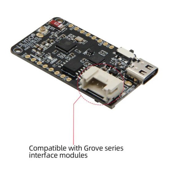
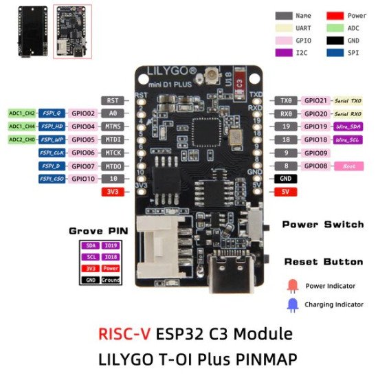
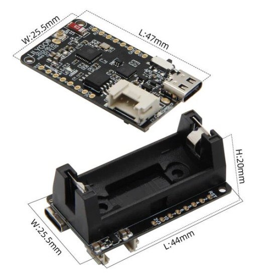


- Stock: Rupture de stock
- Marque: Tiah
- Modèle: DZD004824
- Poids: 15.00g
Description :
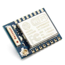
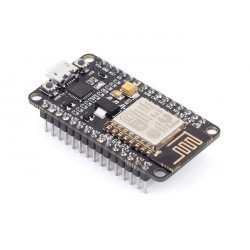
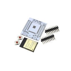
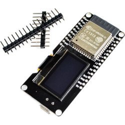
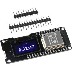
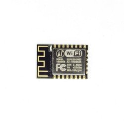
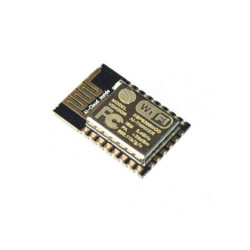
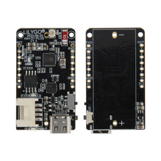
Module ESP32-C3 (RISC-V) pour le Développement Wireless
Le ESP32-C3 est un microcontrôleur (MCU) sans fil qui repose sur une architecture RISC-V et qui offre une connectivité Wi-Fi et Bluetooth LE (Low Energy).
Ce module est particulièrement populaire dans le domaine de l'Internet des objets (IoT) grâce à sa faible consommation énergétique, sa performance élevée et son faible coût.
Il est souvent utilisé dans des projets nécessitant des applications sans fil avec des exigences modérées en termes de puissance de calcul.
Caractéristiques principales de l'ESP32-C3 :
Processeur RISC-V à 32 bits avec une fréquence d'horloge allant jusqu'à 160 MHz.
Connectivité sans fil : Wi-Fi (802.11 b/g/n) et Bluetooth Low Energy (BLE 5.0).
Mémoire : 400 Ko de SRAM et jusqu'à 4 Mo de flash.
Sécurisation : Support de la cryptographie matérielle, comme le chiffrement AES, RSA et SHA.
Alimentation : Faible consommation d'énergie, avec des modes de gestion d'énergie optimisés.
GPIOs : Plusieurs entrées/sorties numériques, PWM, ADC, I2C, SPI, UART, etc.
Circuits de Développement pour l'ESP32-C3
1. Connexion de l'ESP32-C3 à un Ordinateur (Programmation)
Pour programmer l'ESP32-C3, vous devez connecter le module à un ordinateur via un adaptateur USB-UART. Voici un schéma de base pour la programmation de l'ESP32-C3 :
Composants nécessaires :
ESP32-C3
Câble USB vers UART (si le module ESP32-C3 ne possède pas de port USB natif)
Logiciel de programmation (comme Arduino IDE ou PlatformIO)
Schéma de connexion :
TX (de l'ESP32-C3) vers RX (de l'adaptateur USB-UART)
RX (de l'ESP32-C3) vers TX (de l'adaptateur USB-UART)
GND (de l'ESP32-C3) vers GND (de l'adaptateur USB-UART)
3V3 (de l'ESP32-C3) vers 3.3V (de l'adaptateur USB-UART)
Note : Vérifiez les spécifications de votre modèle ESP32-C3 pour vous assurer de la compatibilité en termes de tension (3.3V est la norme pour l'ESP32-C3).
2. Circuit pour la connexion Wi-Fi et Bluetooth
Un des points forts de l'ESP32-C3 est sa capacité à se connecter facilement aux réseaux Wi-Fi et à d'autres appareils via Bluetooth.
Le schéma de base pour utiliser ces fonctions sans fil est très simple car le module possède déjà une antenne intégrée (selon le modèle).
Toutefois, si vous avez besoin de plus de portée, vous pouvez connecter une antenne externe.
Composants nécessaires :
ESP32-C3
Antenne (si externe nécessaire)
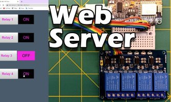
Exemple de projet : Contrôler des appareils via Wi-Fi (par exemple, une LED ou un moteur) en utilisant le serveur Web intégré du module.
Vous pouvez facilement configurer une page web pour contrôler un périphérique à distance.
3. Circuit d'Entrée/Sortie (GPIOs)
L'ESP32-C3 permet de connecter une grande variété de périphériques via ses broches GPIO. Vous pouvez facilement connecter des capteurs, des moteurs, ou des dispositifs d'affichage.
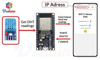
Exemple : Utilisation d'un capteur de température et d'humidité (comme le DHT11/DHT22) avec l'ESP32-C3 pour envoyer les données à un serveur web ou à une application mobile via Wi-Fi.
Schéma de connexion :
GPIO de l'ESP32-C3 vers le Data du capteur (par exemple DHT11)
VCC vers 3.3V
GND vers GND
Exemple de Code (Arduino IDE) pour un Serveur Web sur ESP32-C3
Voici un exemple simple qui montre comment utiliser l'ESP32-C3 pour créer un serveur Web permettant de contrôler une LED via une page HTML.
#include <WiFi.h>
const char *ssid = "votre_SSID";
const char *password = "votre_mot_de_passe";
WiFiServer server(80);
const int ledPin = 2; // Broche GPIO pour la LED
void setup() {
Serial.begin(115200);
pinMode(ledPin, OUTPUT);
// Connexion au réseau Wi-Fi
WiFi.begin(ssid, password);
while (WiFi.status() != WL_CONNECTED) {
delay(1000);
Serial.println("Connexion au réseau...");
}
Serial.println("Connecté au Wi-Fi !");
// Démarre le serveur
server.begin();
}
void loop() {
WiFiClient client = server.available();
if (client) {
String request = client.readStringUntil('\r');
Serial.println(request);
client.flush();
// Contrôle de la LED selon la requête
if (request.indexOf("/LED=ON") != -1) {
digitalWrite(ledPin, HIGH);
} else if (request.indexOf("/LED=OFF") != -1) {
digitalWrite(ledPin, LOW);
}
// Réponse HTML pour le contrôle de la LED
String html = "<html><body><h1>Contrôle de la LED</h1><p><a href=\"/LED=ON\">Allumer la LED</a></p><p><a href=\"/LED=OFF\">Éteindre la LED</a></p></body></html>
Explication du code :
Le code se connecte à un réseau Wi-Fi.
Un serveur HTTP écoute sur le port 80.
Il propose une page web simple avec des liens pour allumer ou éteindre une LED connectée à la broche GPIO 2.
Conclusion
L'ESP32-C3 est un excellent choix pour les projets IoT grâce à ses fonctionnalités puissantes, sa faible consommation d'énergie et son architecture RISC-V.
Vous pouvez facilement l'intégrer dans des circuits de développement pour réaliser des applications sans fil variées, que ce soit pour des capteurs, des contrôles
à distance ou des dispositifs connectés.
GRBL
Mach3

